

Page 1
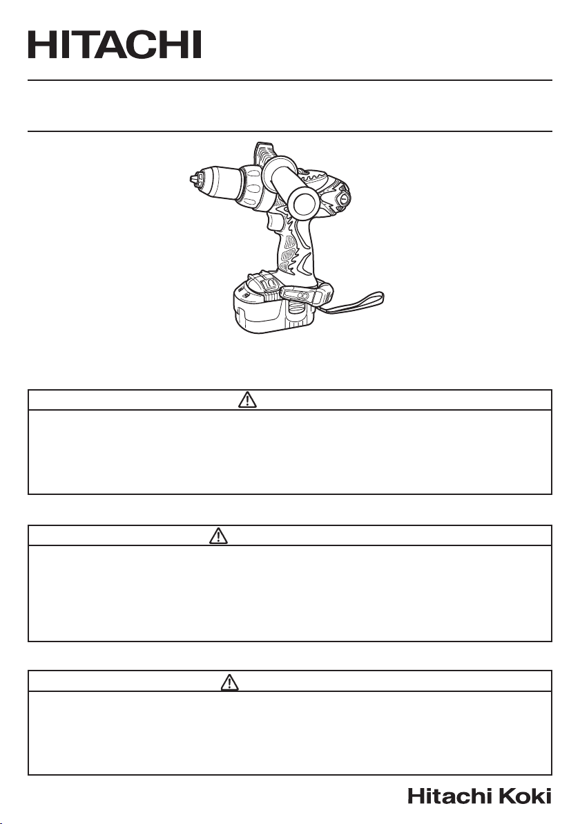
Model Variable speed Cordless Driver Drill
Modèle Perceuse-visseuse à batterie
Modelo
DS 14DMR • DS 18DMR
DS18DMR
Taladro atornillador a batería
SAFETY INSTRUCTIONS AND INSTRUCTION MANUAL
WARNING
IMPROPER OR UNSAFE use of this power tool can result in death or serious bodily
injury!
This manual contains important information about product safety. Please read and
understand this manual BEFORE operating the power tool. Please keep this manual
available for other users and owners before they use the power tool. This manual should
be stored in safe place.
INSTRUCTIONS DE SECURITE ET MODE D’EMPLOI
AVERTISSEMENT
Une utilisation INCORRECTE OU DANGEREUSE de cet outil motorisé peut entraîner la
mort ou de sérieuses blessures corporelles !
Ce mode d’emploi contient d’importantes informations à propos de la sécurité de ce
produit. Prière de lire et de comprendre ce mode d’emploi AVANT d’utiliser l’outil
motorisé. Garder ce mode d’emploi à la disponibilité des autres utilisateurs et propriétaires
avant qu’ils utilisent l’outil motorisé. Ce mode d’emploi doit être conservé dans un
endroit sûr.
INSTRUCCIONES DE SEGURIDAD Y MANUAL DE INSTRUCCIONES
ADVERTENCIA
¡La utilización INAPROPIADA O PELIGROSA de esta herramienta eléctrica puede
resultar en lesiones de gravedad o la muerte!
Este manual contiene información importante sobre la seguridad del producto. Lea y
comprenda este manual ANTES de utilizar la herramienta eléctrica. Guarde este manual
para que puedan leerlo otras personas antes de utilizar la herramienta eléctrica. Este
manual debe ser guardado en un lugar seguro.
Page 2

English
IMPORTANT SAFETY INFORMATION .............. 3
MEANINGS OF SIGNAL WORDS ...................... 3
SAFETY .................................................................... 4
GENERAL SAFETY RULES – FOR ALL
BATTERY OPERATED TOOLS ..................... 4
SPECIFIC SAFETY RULES AND SYMBOLS ....... 6
IMPORTANT SAFETY INSTRUCTIONS
FOR BATTERY CHARGER ........................... 8
IMPORTANT SAFETY INSTRUCTIONS
FOR USE OF THE BATTERY AND
BATTERY CHARGER ...................................... 9
DISPOSAL OF THE EXHAUSTED BATTERY ... 10
FUNCTIONAL DESCRIPTION ................................ 11
MODEL ............................................................... 11
NAME OF PARTS .............................................. 11
SPECIFICATIONS .............................................. 13
CONTENTS
Page
ASSEMBLY AND OPERATION ............................. 14
APPLICATIONS ................................................. 14
REMOVAL AND INSTALLATION METHOD
OF BATTERY .............................................. 14
CHARGING METHOD ....................................... 14
BEFORE USE ....................................................... 19
OPERATION ....................................................... 19
THE SCOPE AND SUGGESTIONS
FOR USES .................................................. 25
HOW TO SELECT TIGHTENING TORQUE ....... 26
MAINTENANCE AND INSPECTION ..................... 27
ACCESSORIES ....................................................... 29
STANDARD ACCESSORIES ............................. 29
OPTIONAL ACCESSORIES ............................... 30
Page
Français
INFORMATIONS IMPORTANTES DE SÉCURITÉ
SIGNIFICATION DES MOTS D’AVERTISSEMENT
SECURITE ................................................................ 32
REGLES GENERALE DE SECURITE – POUR TOUS
LES OUTILS FONCTIONNANT SUR BATTERIE
REGLES DE SECURITE SPECIFIQUES ET SYMBOLES
CONSIGNES DE SÉCURITÉ IMPORTANTES
POUR LE CHARGEUR DE BATTERIE .......... 36
CONSIGNES DE SÉCURITÉ IMPORTANTES
POUR L’UTILISATION DE LA BATTERIE
ET DU CHARGEUR DE BATTERIE .............. 37
MISE AU REBUT D’UNE BATTERIE USÉE ........ 38
DESCRIPTION FONCTIONNELLE ........................... 39
MODELE .............................................................. 39
NOM DES PARTIES ............................................ 39
SPECIFICATIONS ................................................ 41
TABLE DES MATIERES
Page
..... 31
..... 31
.... 32
.. 34
Español
INFORMACIÓN IMPORTANTE SOBRE SEGURIDAD
SIGNIFICADO DE LAS PALABRAS DE SEÑALIZACIÓN
SEGURIDAD ............................................................. 60
NORMAS GENERALES DE SEGURIDAD – PARA TODAS
LAS HERRAMIENTAS ALIMENTADAS CON BATERÍA
NORMAS Y SÍMBOLOS ESPECÍFICOS DE
SEGURIDAD ................................................. 62
INSTRUCCIONES IMPORTANTES DE SEGURIDAD
PARA EL CARGADOR DE BATERÍAS
INSTRUCCIONES IMPORTANTES DE SEGURIDAD
PARA LA BATERÍA Y EL CARGADOR DE BATERÍAS
ELIMINACIÓN DE LAS BATERÍAS AGOTADAS
DESCRIPCIÓN FUNCIONAL .................................... 67
MODELO .............................................................. 67
NOMENCLATURA ............................................... 67
ESPECIFICACIONES ............................................ 69
Página
.... 59
.... 59
... 60
.................. 64
... 65
... 66
ASSEMBLAGE ET FONCTIONNEMENT ................ 42
ENTRETIEN ET INSPECTION .................................. 55
ACCESSOIRES ......................................................... 57
ÍNDICE
MONTAJE Y OPERACIÓN ...................................... 70
MANTENIMIENTO E INSPECCIÓN ........................ 84
ACCESORIOS ........................................................... 86
Page
UTILISATIONS .................................................... 42
MÉTHODE DE RETRAIT ET D’INSTALLATION
DE LA BATTERIE .......................................... 42
MÉTHODE DE RECHARGE ................................. 42
AVANT L’UTILISATION ...................................... 48
UTILISATION ....................................................... 48
PLAGE D’UTILISATION ET SUGGESTIONS ..... 54
SÉLECTION DU COUPLE DE SERRAGE ............ 54
ACCESSOIRES STANDARD ............................... 57
ACCESSOIRES EN OPTION ................................ 58
Página
APLICACIONES ................................................... 70
MÉTODO DE EXTRACCIÓN E INSTALACIÓN
DE LA BATERÍA ............................................ 70
MÉTODO DE CARGA .......................................... 70
ANTES DE LA UTILIZACIÓN .............................. 76
OPERACIÓN ........................................................ 76
ALCANCE Y SUGERENCIAS PARA LA
UTILIZACIÓN ................................................ 82
FORMA DE SELECCIONAR EL PAR DE APRIETE
ACCESORIOS ESTÁNDAR ................................. 86
ACCESORIOS OPCIONALES .............................. 87
... 83
Page 3

English
IMPORTANT SAFETY INFORMATION
Read and understand all of the safety precautions, warnings and operating instructions in
the Instruction Manual before operating or maintaining this power tool.
Most accidents that result from power tool operation and maintenance are caused by the
failure to observe basic safety rules or precautions. An accident can often be avoided by
recognizing a potentially hazardous situation before it occurs, and by observing appropriate
safety procedures.
Basic safety precautions are outlined in the “SAFETY” section of this Instruction Manual
and in the sections which contain the operation and maintenance instructions.
Hazards that must be avoided to prevent bodily injury or machine damage are identified by
WARNINGS on the power tool and in this Instruction Manual.
NEVER use this power tool in a manner that has not been specifically recommended by
HITACHI.
MEANINGS OF SIGNAL WORDS
WARNING indicates a potentially hazardous situations which, if ignored, could result in
death or serious injury.
CAUTION indicates a potentially hazardous situations which, if not avoided, may result in
minor or moderate injury, or may cause machine damage.
NOTE emphasizes essential information.
3
Page 4

English
SAFETY
GENERAL SAFETY RULES – FOR ALL BATTERY OPERATED TOOLS
WARNING: Read and understand all instructions.
Failure to follow all instructions listed below, may result in electric shock,
fire and/or serious personal injury.
SAVE THESE INSTRUCTIONS
1. Work Area
(1) Keep your work area clean and well lit. Cluttered benches and dark areas invite
accidents.
(2) Do not operate power tools in explosive atmospheres, such as in the presence of
flammable liquids, gases, or dust. Power tools create sparks which may ignite the
dust of fumes.
(3) Keep bystanders, children and visitors away while operating a power tool.
Distractions can cause you to lose control.
2. Electrical Safety
(1) A battery operated tool with integral batteries or a separate battery pack must be
recharged only with the specified charger for the battery.
A charger that may be suitable for one type of battery may create a risk of fire when
used with another battery.
(2) Use battery operated tool only with specifically designed battery pack.
Use of any other batteries may create a risk of fire.
3. Personal Safety
(1) Stay alert, watch what you are doing and use common sense when operating a
power tool. Do not use tool while tired or under the influence of drugs, alcohol, or
medication. A moment of inattention while operating power tools may result in
serious personal injury.
(2) Dress properly. Do not wear loose clothing or jewelry. Contain long hair. Keep
your hair, clothing and gloves away from moving parts. Loose clothes, jewelry, or
long hair can be caught in moving parts.
(3) Avoid accidental starting. Be sure switch is off position before inserting battery.
Carrying tools with your finger on the switch or inserting the battery pack into a
tool that have the switch on invites accidents.
(4) Remove adjusting keys or wrenches before turning the tool on. A wrench or a key
that is left attached to a rotating part of the tool may result in personal injury.
(5) Do not overreach. Keep proper footing and balance at all times. Proper footing and
balance enable better control of the tool in unexpected situations.
(6) Use safety equipment. Always wear eye protection. Dust mask, non-skid safety
shoes, hard hat, or hearing protection must be used for appropriate conditions.
4
Page 5

4. Tool Use and Care
(1) Use clamps or other practical way to secure and support the workpiece to a stable
platform. Holding the work by hand or against your body is unstable and may lead
to loss of control.
(2) Do not force tool. Use the correct tool for your application. The correct tool will do
the job better and safer at the rate for which it is designed.
(3) Do not use tool if switch does not turn it on or off. Any tool that cannot be controlled
with the switch is dangerous and must be repaired.
(4) Disconnect battery pack from tool or place the switch in the locked or off position
before making any adjustments, changing accessories, or storing the tools. Such
preventive safety measures reduce the risk of starting the tool accidentally.
(5) Store idle tools out of reach of children and other untrained persons. Tools are
dangerous in the hands of untrained users.
(6) When battery pack is not in use, keep it away from other metal objects like: paper
clips, coins, keys, nails, screws, or other small metal objects that can make a
connection from one terminal to another.
Shorting the battery terminals together may cause sparks, burns, or a fire.
(7) Maintain tools with care. Keep cutting tools sharp and clean. Properly maintained
tools, with sharp cutting edges are less likely to bind and are easier to control.
(8) Check for misalignment or binding of moving parts, breakage of parts, and any
other condition that may affect the tools operation. If damaged, have the tool
serviced before using. Many accidents are caused by poorly maintained tools.
(9) Use only accessories that are recommended by the manufacturer for your model.
Accessories that may be suitable for one tool, may become hazardous when used
on another tool.
5. Service
(1) Tool service must be performed only by qualified repair personnel. Service or
maintenance performed by unqualified personnel could result in a risk of injury.
(2) When servicing a tool, use only identical replacement parts. Follow instructions in
the Maintenance section of this manual. Use of unauthorized parts or failure to
follow Maintenance Instruction may create a risk of electric shock or injury.
English
WARNING:
Some dust created by power sanding, sawing, grinding, drilling, and other construction
activities contains chemicals known to the State of California to cause cancer, birth defects
or other reproductive harm. Some examples of these chemicals are:
● Lead from lead-based paints,
● Crystalline silica from bricks and cement and other masonry products, and
● Arsenic and chromium from chemically-treated lumber.
Your risk from these exposures varies, depending on how often you do this type of
work. To reduce your exposure to these chemicals: work in a well ventilated area, and
work with approved safety equipment, such as those dust masks that are specially
designed to filter out microscopic particles.
5
Page 6
English
SPECIFIC SAFETY RULES AND SYMBOLS
1. Hold tools by insulated gripping surfaces when performing an operation where the
cutting tool may contact hidden wiring. Contact with a “live” wire will make exposed
metal parts of the tool “live” and shock the operator.
2. ALWAYS wear ear protectors when using the tool for extended periods.
Prolonged exposure to high intensity noise can cause hearing loss.
3. NEVER place hands or other body parts near the drill bit or chuck during operation.
Hold the drill by its handle only.
4. Because the cordless driver drill operates by battery power, be aware of the fact that it
can begin to operate at any time.
5. When working at elevated locations, clear the area of all other people and be aware of
conditions below you.
6. NEVER touch moving parts.
NEVER place your hands, fingers or other body parts near the tool’s moving parts.
7. NEVER operate without all guards in place.
NEVER operate this tool without all guards or safety features in place and in proper
working order. If maintenance or servicing requires the removal of a guard or safety
feature, be sure to replace the guard or safety feature before resuming operation of the
tool.
8. Use right tool.
Don’t force small tool or attachment to do the job of a heavy-duty tool.
Don’t use tool for purpose not intended —for example— don’t use circular saw for
cutting tree limbs or logs.
9. NEVER use a power tool for applications other than those specified.
NEVER use a power tool for applications other than those specified in the Instruction
Manual.
10. Handle tool correctly.
Operate the tool according to the instructions provided herein. Do not drop or throw
the tool. NEVER allow the tool to be operated by children, individuals unfamiliar with
its operation or unauthorized personnel.
11. Keep all screws, bolts and covers tightly in place.
Keep all screws, bolts, and plates tightly mounted. Check their condition periodically.
12. Do not use power tools if the plastic housing or handle is cracked.
Cracks in the tool’s housing or handle can lead to electric shock. Such tools should not
be used until repaired.
13. Blades and accessories must be securely mounted to the tool.
Prevent potential injuries to yourself or others. Blades, cutting implements and
accessories which have been mounted to the tool should be secure and tight.
6
Page 7
English
14. NEVER use a tool which is defective or operating abnormally.
If the tool appears to be operating unusually, making strange noises, or otherwise
appears defective, stop using it immediately and arrange for repairs by a Hitachi
authorized service center.
15. Carefully handle power tools.
Should a power tool be dropped or struck against hard materials inadvertently, it may
be deformed, cracked, or damaged.
16. Do not wipe plastic parts with solvent.
Solvents such as gasoline, thinner, benzine, carbon tetrachloride and alcohol may
damage and crack plastic parts. Do not wipe them with such solvents.
Wipe plastic parts with a soft cloth lightly dampened with soapy water and dry
thoroughly.
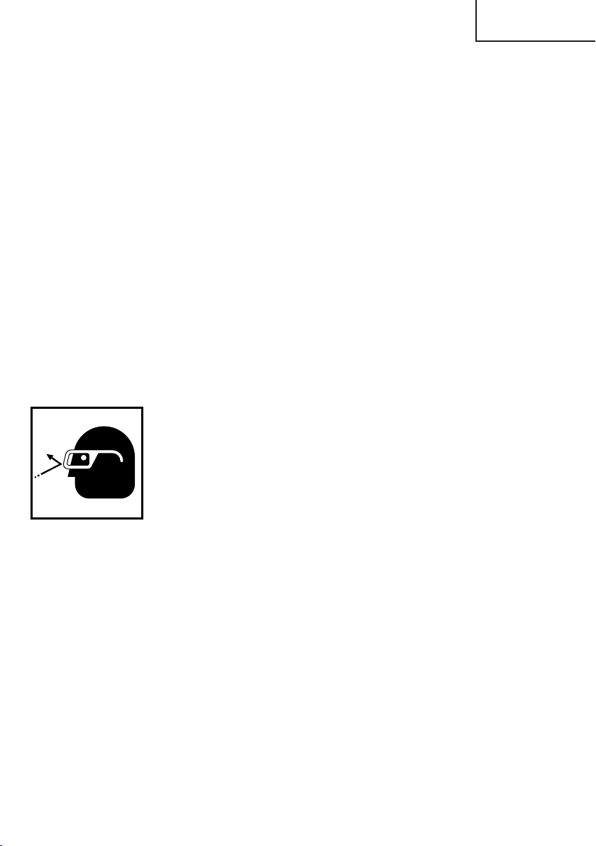
17. ALWAYS wear eye protection that meets the requirement of the latest revision of ANSI
Standard Z87.1.
18. Definitions for symbols used on this tool
............
V
—
---
no
---/min
volts
...........
direct current
..........
no load speed
...
revolutions per minute
7
Page 8

English
IMPORTANT SAFETY INSTRUCTIONS
FOR BATTERY CHARGER
1. This manual contains important safety and operating instructions for battery charger
Model UC14YFA/UC24YJ.
2. Before using battery charger, read all instructions and cautionary markings on (1) battery
charger, (2) battery, and (3) product using battery.
3. To reduce risk of injury, charge HITACHI rechargeable battery type EB7, EB9, EB12,
EB14, EB18 series and EB24B. Other type of batteries may burst causing personal injury
and damage.
4. Do not expose battery charger to rain or snow.
5. Use of an attachment not recommended or sold by the battery charger manufacturer
may result in a risk of fire, electric shock, or injury to persons.
6. To reduce risk of damage to electric plug and cord, pull by plug when disconnecting
battery charger.
7. Make sure cord is located so that it will not be stepped on, tripped over, or otherwise
subjected to damage or stress.
8. An extension cord should not be used unless absolutely necessary. Use of improper
extension cord could result in a risk of fire and electric shock.
If extension cord must be used make sure:
a. That blades of extension cord are the same number, size, and shape as those of
plug on battery charger;
b. That extension cord is properly wired and in good electrical condition; and
c. That wire size is large enough for AC ampere rating of battery charger as specified
in Table 1.
Table 1
RECOMMENDED MINIMUM AWG SIZE FOR
EXTENSION CORDS FOR BATTERY CHARGERS
AC Input Rating Amperes* AWG Size of Cord
Equal to or but less Length of Cord, Feet (Meter)
greater than than 25 (7.5) 50 (15) 100 (30) 150 (45)
0 2 18 18 18 16
2 3 18 18 16 14
3 4 18 18 16 14
* If the input rating of a battery charger is given in watts rather than in amperes, the
corresponding ampere rating is to be determined by dividing the wattage rating by the
voltage rating–for example:
1250 watts
125 volts
9. Do not operate battery charger with damaged cord or plug–replace them immediately.
8
= 10 amperes
Page 9

English
10. Do not operate battery charger if it has received a sharp blow, been dropped, or otherwise
damaged in any way; take it to a qualified serviceman.
11. Do not disassemble battery charger; take it to a qualified serviceman when service or
repair is required. Incorrect reassembly may result in a risk of electric shock or fire.
12. To reduce risk of electric shock, unplug charger from receptacle before attempting any
maintenance or cleaning. Removing the battery will not reduce this risk.
IMPORTANT SAFETY INSTRUCTIONS FOR USE OF THE
BATTERY AND BATTERY CHARGER
You must charge the battery before you can use the cordless driver drill. Before using the
model UC14YFA/UC24YJ battery charger, be sure to read all instructions and cautionary
statements on it, the battery and in this manual.
REMEMBER: USE ONLY HITACHI BATTERY TYPES EB7 SERIES, EB9 SERIES, EB12 SERIES,
EB14 SERIES, EB18 SERIES AND EB24B. OTHER TYPES OF BATTERIES MAY BURST AND
CAUSE INJURY!
Follow these instructions to avoid the risk of injury:
WARNING: Improper use of the battery or battery charger can lead to serious injury.
To avoid these injuries:
1. NEVER disassemble the battery.
2. NEVER incinerate the battery, even if it is damaged or is completely worn out. The
battery can explode in a fire.
3. NEVER short-circuit the battery.
4. NEVER insert any objects into the battery charger’s air vents. Electric shock or
damage to the battery charger may result.
5. NEVER charge outdoors. Keep the battery away from direct sunlight and use only
where there is low humidity and good ventilation.
6. NEVER charge when the temperature is below 32°F (0°C) or above 104°F (40°C).
7. NEVER connect two battery chargers together.
8. NEVER insert foreign objects into the hole for the battery or the battery charger.
9. NEVER use a booster transformer when charging.
10. NEVER use an engine generator or DC power to charge.
11. NEVER store the battery or battery charger in places where the temperature may
reach or exceed 104°F (40°C).
12. ALWAYS operate charger on standard household electrical power (120 volts). Using
the charger on any other voltage may overheat and damage the charger.
13. ALWAYS wait at least 15 minutes between charges to avoid overheating the charger.
14. ALWAYS disconnect the power cord from its receptacle when the charger is not in
use.
9
Page 10

English
DISPOSAL OF THE EXHAUSTED BATTERY
WARNING: Do not dispose of the exhausted battery. The battery must explode if it
is incinerated. The product that you have purchased contains a
rechargeable battery. The battery is recyclable. At the end of it’s useful
life, under various state and local laws, it may be illegal to dispose of
this battery into the municipal waste stream. Check with your local
solid waste officials for details in your area for recycling options or
proper disposal.
SAVE THESE INSTRUCTIONS
AND
MAKE THEM AVAILABLE TO
OTHER USERS
AND
OWNERS OF THIS TOOL!
10
Page 11
FUNCTIONAL DESCRIPTION
NOTE:
The information contained in this Instruction Manual is designed to assist you in the
safe operation and maintenance of the power tool.
NEVER operate, or attempt any maintenance on the tool unless you have first read and
understood all safety instructions contained in this manual.
Some illustrations in this Instruction Manual may show details or attachments that
differ from those on your own power tool.
MODEL
DS14DMR (BFK): with charger (UC14YFA) and case
DS18DMR (HLCK): with charger (UC24YJ) and case
NAME OF PARTS
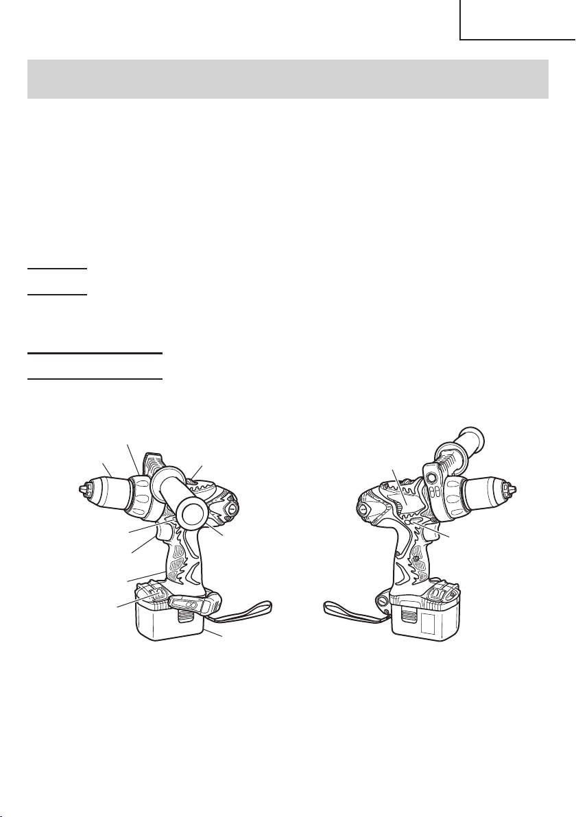
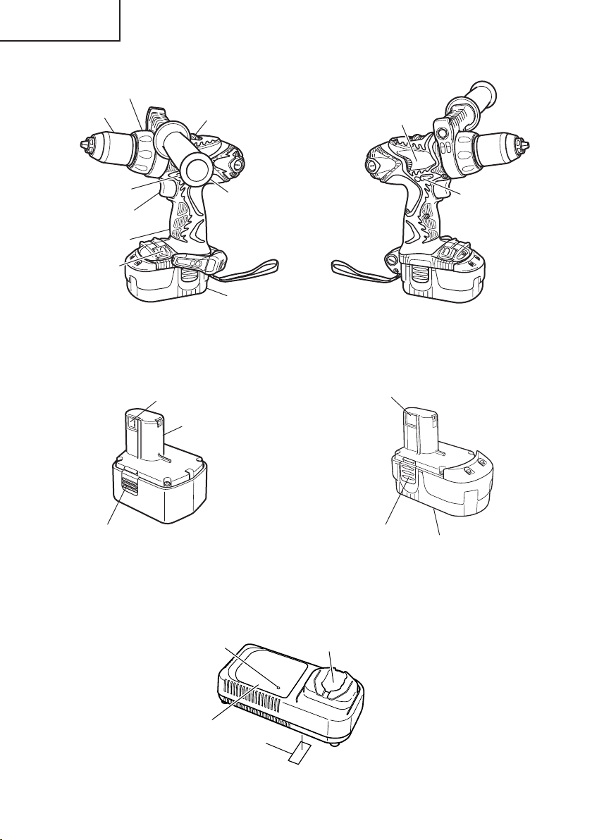
1. Cordless Driver Drill (DS14DMR and DS18DMR)
<DS14DMR>
English
Keyless Chuck
Push Button
Switch Trigger
Handle
Bit Holder
Cap
Shift Knob
Side Handle
Battery
Nameplate
Push Button
11
Page 12
English
<DS18DMR>
Keyless Chuck
Cap
Shift Knob
Nameplate
Push Button
Switch Trigger
Handle
Bit Holder
䡬 Battery (EB14B)
(For DS14DMR)
Latch
Battery
Terminal Hole
Nameplate
Side Handle
Fig. 1
䡬 Battery (EB1830HL)
(For DS18DMR)
Terminal Hole
Latch
Nameplate
Push Button
2. Battery Charger
<UC14YFA for DS14DMR>
Pilot Lamp
Caution Plate
12
Battery Installation Hole
Nameplate
Fig. 2
Page 13
English
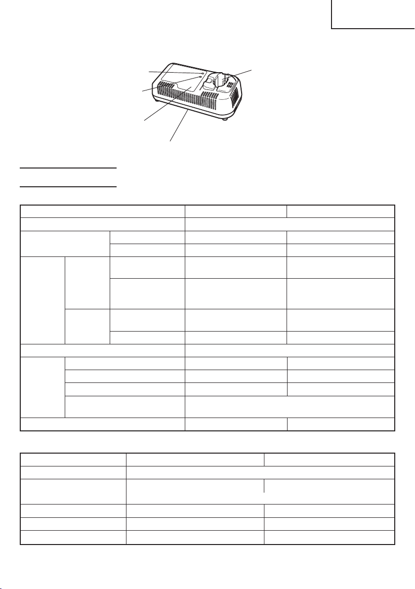
<UC24YJ for DS18DMR>
Charge Time Lamp
Charge
Status Lamp
Caution Plate
Nameplate
Fig. 3
Battery
Installation Hole
SPECIFICATIONS
1. Cordless Driver Drill
Model DS14DMR DS18DMR
Motor DC motor
No-load speed Low 0–400/min 0–400/min
High 0–1500/min 0–1600/min
Capacity Drilling
Screw Wood screw #20 × 3" #20 × 4"
Driver
Drill chuck capacity Maximum gripping diameter 1/2" (13 mm)
Battery Model EB14B EB1830HL
Type
Voltage DC 14.4 V DC 18 V
Charging & discharging
frequency
Weight 5.1 lbs. (2.3 kg) 5.5 lbs. (2.5 kg)
Wood (Thickness
11/16" (18 mm)) (Soft Wood) (Soft Wood)
Metal (Thickness
1/16" (1.6 mm)) (Mild Steel or (Mild Steel or
Small screw 1/4" (6 mm) 1/4" (6 mm)
1-3/4"
(44 mm)
1/2" (13 mm) 1/2" (13 mm)
Aluminum) Aluminum)
(8 mm × 75 mm) (8 mm × 100 mm)
Nickel cadmium battery
about 1000
2" (50 mm)
Nickel-Metal Hydride battery
2. Battery Charger
Model UC14YFA UC24YJ
Input power source Single phase: AC 120 V 60 Hz
Charging time Approx. 50 min. Approx. 28min
(At a temperature of 68°F (20°C))
Charging voltage DC 7.2–14.4 V DC 7.2–24 V
Charging current DC 2.6 A DC 7.5 A
Weight 1.3 lbs. (0.6 kg) 2.2 lbs. (1.0 kg)
NOTE: The charging time may vary according to temperature and power source voltage.
13
Page 14
English
ASSEMBLY AND OPERATION
APPLICATIONS
䡬 Use as a drill
Drilling of soft steel, wood, plastic and aluminum materials
䡬 Use as a screwdriver
Tightening and loosening of machine screws, wood screws and tapping screws
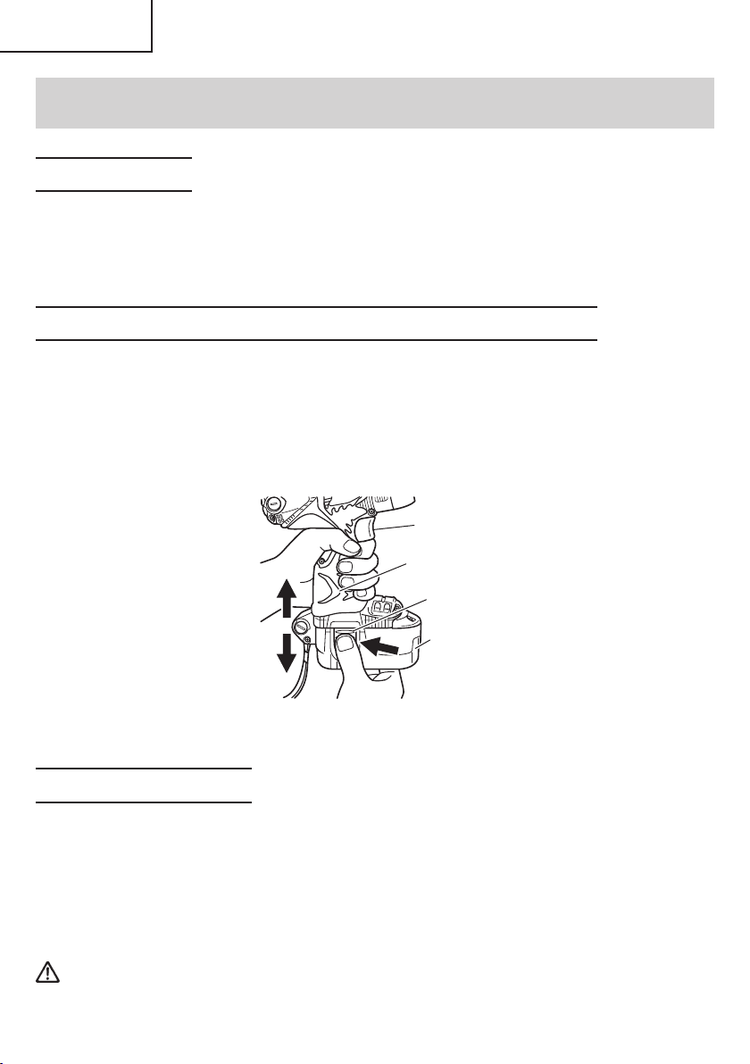
REMOVAL AND INSTALLATION METHOD OF BATTERY
䡬 How to install the battery
Align the battery with the groove in tool handle and slip it into place.
Always insert it all the way until it locks in place with a little click. If not, it may accidentally
fall out of the tool, causing injury to you or someone around you. (Fig. 4)
䡬 How to remove the battery
Withdraw battery from the tool handle while pressing the latch (2 pcs.) on the sides of
the battery. (Fig. 4)
Switch Trigger
Insert
Pull out
Fig. 4
Handle
Latch
Battery
Push
CHARGING METHOD
The following is an explanation of charging methods when using the battery charger
UC14YFA or UC24YJ. When charging using the ET18DM Multi Charger, please read the
separate ET18DM Instruction manual.
NOTE: Before plugging into the receptacle, make sure the following points.
䡬 The power source voltage is stated on the nameplate.
䡬 The cord is not damaged.
WARNING: Do not charge at voltage higher than indicated on the nameplate.
If charged at voltage higher than indicated on the nameplate, the
charger will burn up.
14
Page 15
English
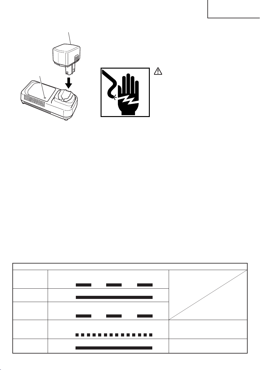
Battery
<UC14YFA>
1. Insert the plug of battery charger into the receptacle.
When the plug of battery charger has been inserted into
the receptacle, pilot lamp will blink in red. (At 1-second
intervals)
Pilot Lamp
WARNING:
Do not use the electrical cord if
damaged. Have it repaired
immediately.
Fig. 5
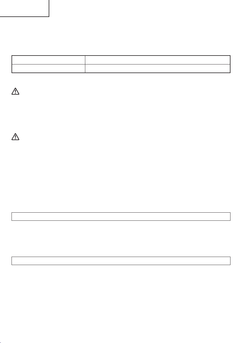
2. Insert the battery to the battery charger.
Insert the battery into the battery charger as shown in Fig. 5. Make sure it contacts the
bottom of the battery charger.
3. Charging
When the battery is connected to the battery charger, charging will commence and the
pilot lamp will light in red. (See Table 2)
NOTE: If the pilot lamp flickers in red, pull out the plug from the receptacle and check if
the battery is properly mounted.
When the battery is fully charged, the pilot lamp will blink in red slowly. (At 1-second
intervals) (See Table 2)
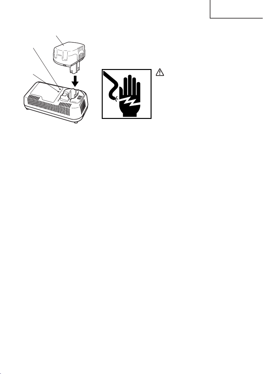
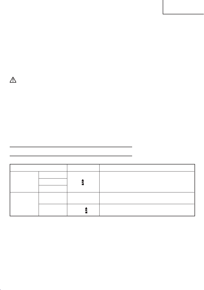
(1) Pilot lamp indication
The indications of the pilot lamp will be as shown in Table 2, according to the condition
of the charger or the rechargeable battery.
Table 2
Indications of the pilot lamp
Before
charging
While
charging
Charging
complete
Charging
impossible
Charging
impossible
Blinks
(RED)
Lights
(RED)
Blinks
(RED)
Flickers
(RED)
Lights
(GREEN)
Lights for 0.5 seconds. Does not light for
0.5 seconds. (off for 0.5 seconds)
Lights continuously
Lights for 0.5 seconds. Does not light for
0.5 seconds. (off for 0.5 seconds)
Lights for 0.1 seconds. Does not light for
0.1 seconds. (off for 0.1 seconds)
Lights continuously
Malfunction in the battery or the
charger
The battery temperature is high,
making recharging impossible.
15
Page 16
English
(2) Regarding the temperature of the rechargeable battery
The temperatures for rechargeable batteries are as shown in the table below, and
batteries that have become hot should be cooled for a while before being recharged.
Table 3 Recharging of batteries that have become hot
Rechargeable batteries Temperatures at which the battery can be recharged
EB14B 23°F—140°F (–5°C—60°C)
4. Disconnect battery charger from the receptacle.
CAUTION:
Do not pull the plug out of the receptacle by pulling on the cord.
Make sure to grasp the plug when removing from receptacle to avoid damaging cord.
5. Remove the battery from the battery charger.
Supporting the battery charger with hand, pull out the battery from the battery charger.
CAUTION:
● When the battery charger has been continuosly used, the battery charger will be heated,
thus constituting the cause of the failures. Once the charging has been completed,
give 15 minutes rest until the next charging.
● If the battery is rechraged when it is warm due to battery use or exposure to sunlight,
the pilot lamp may light in green.
The battery will not be recharged. In such a case, let the battery cool before charging.
● When the pilot lamp flickers in red (at 0.2–second intervals), check for and take out
any foreign objects in the charger’s battery installation hole. If there are no foreign
objects, it is probable that the battery or charger is malfunctioning. Take it to your
authorized Service Center.
Regarding electric discharge in case of new batteries, etc.
As the internal chemical substance of new batteries and batteries that have not been
used for an extended period is not activated, the electric discharge might be low when
using them the first and second time. This is a temporary phenomenon, and normal
time required for recharging will be restored by recharging the batteries 2 – 3 times.
How to make the batteries perform longer
(1) Recharge the batteries before they become completely exhausted.
When you feel that the power of the tool becomes weaker, stop using the tool and
recharge its battery. If you continue to use the tool and exhaust the electric current, the
battery may be damaged and its life will become shorter.
(2) Avoid recharging at high temperatures.
A rechargeable battery will be hot immediately after use. If such a battery is recharged
immediately after use, its internal chemical substance will deteriorate, and the battery
life will be shortened. Leave the battery and recharge it after it has cooled for a while.
16
Page 17
English
Battery
Charge Time
Lamp
Charge
Status Lamp
Fig. 6
<UC24YJ>
1. Insert the plug of battery charger into the receptacle.
When the plug of battery charger has been inserted into
the receptacle, the charge status lamp will blink in red.
(At 1-second intervals)
WARNING:
Do not use the electrical cord if
damaged. Have it repaired
immediately.
2. Insert the battery to the battery charger.
Insert the battery into the battery charger as shown in Fig. 6. Make sure it contacts the
bottom of the battery charger.
3. Charging
When the battery is connected to the battery charger, charging starts, and the charge
time lamp lights red, orange, or green according to the remaining charging time. (See
Table 4)
(1) Lamp indications
This charger is equipped with a charge time lamp that indicates remaining charging
time, and a charge status lamp that indicates battery status as shown in Table 4.
(a) Charging time
After charging commences, the charge time lamp lights red indicating 30 minutes,
orange indicating 20 minutes, and green indicating 5 minutes until completion.
When the battery is fully charged, the charge status lamp lights green, and the
buzzer sounds continuously for 6 seconds.
(b) Overheat standby
When the battery is overheated, it cannot be charged, and the charge time lamp
flashes red (in 0.6 second intervals). Leave the battery inserted in the charger, and
charging will commence when the battery cools down.
(c) Charging impossible
When there is a malfunction with the battery or charger, the charge status lamp
flashes orange rapidly (in 0.2 second intervals), and the buzzer sounds intermittently
for 5 seconds.
17
Page 18
English
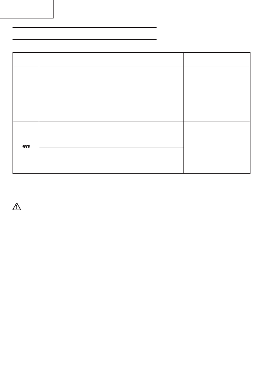
Table 4 Lamp indications
Lamp indications Status lamp
Charging time Lights Lights continuously
Charge
time Charging time Lights Lights continuously
lamp
(red/ Charging time Lights Lights continuously
orange/
green)
Charge
status
lamp
(red/
orange/
green)
30 minutes red
20 minutes orange
5 minutes green
Overheat standby
Before charging
Charging complete
Charging Blinks
impossible orange ■■■■■■■■■■■
Blinks
red
Blinks
red receptacle.
Lights Lights continuously
green
Lights for 0.3 seconds, off 0.3 seconds
Lights for 0.5 seconds, off 0.5 seconds
Lights for 0.1 seconds, off 0.1 seconds
(2) Regarding the temperature of the rechargeable battery
The temperatures for rechargeable batteries are as shown in the table below, and
batteries that have become hot should be cooled for a while before being recharged.
Table 5 Recharging of batteries that have become hot
Rechargeable batteries Temperatures at which the battery can be recharged
EB1830HL 32°F—122°F (0°C—50°C)
30 minutes until charging complete.
20 minutes until charging complete.
5 minutes until charging complete.
Battery overheated. Unable to charge.
(Charging will commence when battery cools.)
Power cord is connected to
Battery or charger malfunction.
4. Disconnect battery charger from the receptacle.
CAUTION:
Do not pull the plug out of the receptacle by pulling on the cord.
Make sure to grasp the plug when removing from receptacle to avoid damaging cord.
5. Remove the battery from the battery charger.
Supporting the battery charger with hand, pull out the battery from the battery charger.
CAUTION:
● Repair is required if the receptacle is not secured properly or the power cord does not
stay in the receptacle. Consult your electrician. Using the charger in this condition
may lead to fire.
● If the charge status lamp is blinking orange rapidly (in 0.2 second intervals) and the
buzzer sounds intermittently for 5 seconds, check that the hole for connecting the
battery is not obstructed. Remove any obstructions. If no obstructions are found, the
battery or charger may be malfunctioned. Return both to your place of purchase.
● If the charge time lamp does not light when the power cord is connected to the
receptacle, disconnect the power cord, and check that the battery is attached correctly.
● The battery retains heat when used or left for prolonged periods in direct sunlight. In
this state, the charge time lamp flashes red, and the battery cannot be charged
immediately. Leave the battery inserted in the charger, and charging will commence
when the battery cools down.
18
Page 19

English
● If the lamp goes out while charging, disconnect the power cord, and leave for 3 to 5
minutes before reconnecting. If the problem persists, call for repairs.
● Leave 5 minutes between charging batteries as the charger may overheat leading to
malfunction.
● The battery life is finished if it can only be used for short periods even when fully
charged. Purchase a new battery. Continuing to use a depleted battery may cause the
charger to malfunction.
NOTE:
䡬 Charging times may be longer depending on the surrounding temperature and battery
conditions.
䡬 Charge time lamp indications are only a guide, and may vary depending on the
surrounding temperature and battery conditions.
䡬 Remove the battery from the charger when not in use.
Revitalizing the battery (trickle recharge)
A new battery or a battery that has not been used for extensive periods may not charge
completely due to internal chemicals being inert.
Leave the battery inserted in the charger for 8 to 12 hours after charging is complete.
The charger automatically “revitalizes” the battery by trickle recharging.
How to make the batteries perform longer
(1) Recharge the batteries before they become completely exhausted.
When you feel that the power of the tool becomes weaker, stop using the tool and
recharge its battery. If you continue to use the tool and exhaust the electric current, the
battery may be damaged and its life will become shorter.
(2) Avoid recharging at high temperatures.
A rechargeable battery will be hot immediately after use. If such a battery is recharged
immediately after use, its internal chemical substance will deteriorate, and the battery
life will be shortened. Leave the battery and recharge it after it has cooled for a while.
BEFORE USE
Check the work area to make sure that it is clear of debris and clutter.
Clear the area of unnecessary personnel. Ensure that lighting and ventilation is adequate.
OPERATION
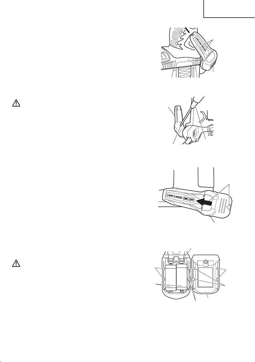
1. Using the light equipped hook
WARNING: When using the hook, pay sufficient attention so that the main
equipment does not fall. If the tool falls, there is a risk of accident.
19
Page 20
English
CAUTION:
● Do not attach the tip tool except phillips bit to the tool main unit when carrying the
tool main unit with the hook suspended from a waist belt.
Injury may result if you carry the equipment suspended from the waist belt with sharp
tipped components such as drill bit attached.
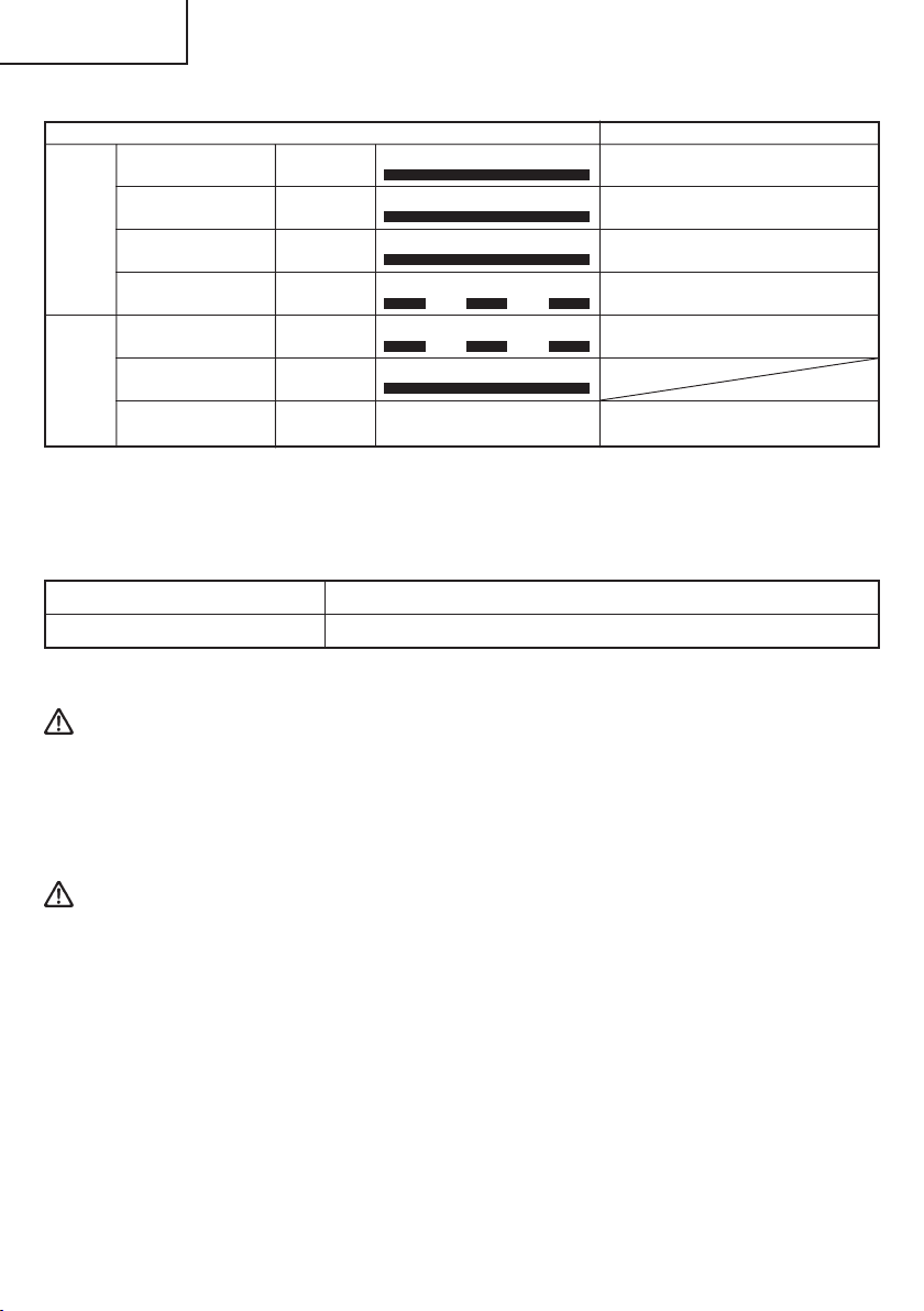
1.1 Using the hook
The hook can be installed on the right or left side
and the angle can be adjusted in 5 steps between
0° and 80°.
(1) Operating the hook
(a) Pull out the hook toward you in the direction
3
2
(B)
1
of arrow (A) and turn in the direction of arrow
(B). (Fig. 7)
(b) The angle can be adjusted in 5 steps (0°, 20°,
40°, 60°, 80°).
Adjust the angle of the hook to the desired
position for use.
(2) Switching the hook position
CAUTION:
● If the tool falls, there is a risk that malfunction
and/or physical damage can occur. It is
Loosen
recommended that you also use fall-preventing
wires, etc.
● Incomplete installation of the hook may result in
bodily injury when used.
(a) Securely hold the main unit and remove the
screw using a slotted head screwdriver or a
coin. (Fig. 8)
(b) Remove the hook and spring. (Fig. 9)
(c) Install the hook and spring on the other side
and securely fasten with screw. (Fig. 8)
NOTE:
Hook
Pay attention to the spring orientation.
Install the spring with larger diameter
away from you. (Fig. 10)
4
Fig. 7
Screw
Fig. 8
Fig. 9
5
(A)
Hook
Spring
Screw
Larger diameter faces away
Fig. 10
20
Page 21
1.2 Using as an auxiliary light
(1) Press the switch to turn off the light.
If forgotten, the light will turn off
automatically after 15 minutes.
(2) The direction of the light can be adjusted
within the range of hook positions 1 - 5. (Fig.
11)
䡬 Lighting time
AAAA manganese batteries: approx. 15
hrs.
AAAA alkali batteries: approx. 30 hrs.
English
Switch
Hook
Fig. 11
CAUTION:
Hook
● Do not look directly into the light.
Such actions could result in eye injury.
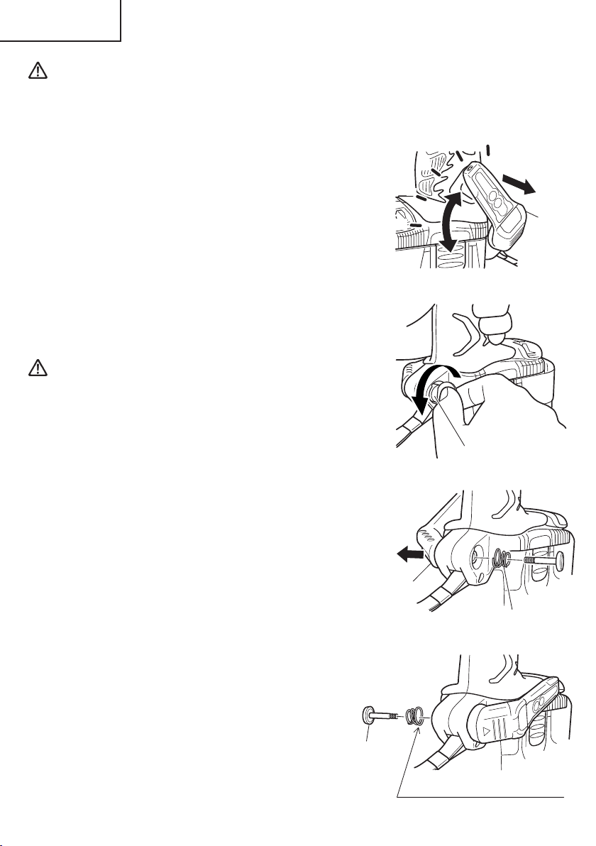
1.3 Replacing the batteries
(1) Loosen the hook screw with a phillips-head
screwdriver (No. 1). (Fig. 12)
Remove the hook cover by pushing in the
direction of the arrow. (Fig. 13)
Screw
Fig. 12
Phillips-head
screwdriver
(2) Remove the old batteries and insert the new
batteries. Align with the hook indications and
position the plus (+) and minus (-) terminals
correctly. (Fig. 14)
Arrow
(3) Align the indentation in the hook main body
with the protuberance of the hook cover,
press the hook cover in the direction opposite
to that of the arrow shown in Fig. 13 and then
tighten the screw.
Use commercially available AAAA batteries
(1.5 V).
NOTE:
Do not tighten the screw excessively. Such
Fig. 13
Hook main body
Hook cover
action could strip the screw threads.
CAUTION:
● Failure to observe the following can result
in battery leakage, rust or malfunction.
Position the plus (+) and minus (-) terminals
correctly.
Replace both batteries at the same time. Do
not mix old and new batteries.
Remove exhausted batteries from the hook
Indentation
AAAA
batteries
Indentation
Fig. 14
Protuberance
Protuberance
Hook cover
immediately.
● Do not discard batteries together with normal trash and do not throw batteries into
fire.
21
Page 22
English
● Store batteries out of the reach of children.
● Use batteries correctly in accordance with the battery specifications and indications.
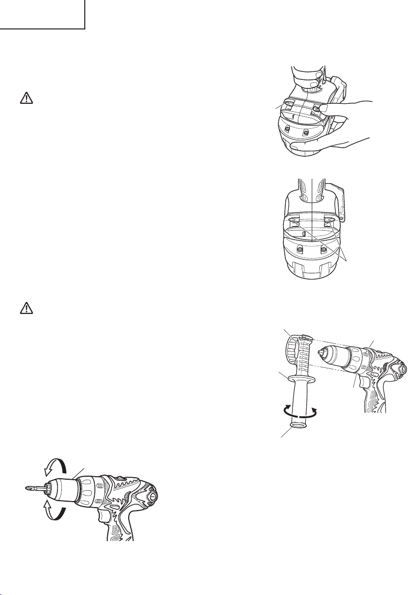
2. Using the bit holder
CAUTION:
● Stow the bit in the specified location on the tool. If
the tool is used with the bit stowed improperly,
the bit may fall and cause bodily injury.
● Do not stow bits that are of a different length,
gauge or dimension than the plus driver bit (65 mm
long) included in the STANDARD ACCESSORIES.
The bit may fall and cause bodily injury.
(1) Removing the bit
Securely hold the main unit and pull out the bit by
holding the tip with your thumb.
(2) Installing the Bit
Install the bit with steps opposite of when removing.
Insert the bit so that the right and left sides are
equal, as shown in Fig. 16.
3. Installing/Removing the side handle
CAUTION:
● Firmly install the side handle. If loose, the side
handle may gyrate or fall out and cause bodily
injury.
(1) Install the side handle so that the protrusions on
the main unit and grooves on the side handle
interlock. Tighten the grip after checking that the
side handle is not riding on the slip prevention
protrusion. (Fig. 17)
(2) Loosen the grip to remove the side handle.
Bit
Concave
Side
handle
Loosen
Fig. 15
Insert so that
bit does not
protrude
from main unit
Fig. 16
Rotate preventing
protrusion
Slip preventing
protrusion
Tighten
4. Mounting and dismounting the bit
Loosen
Tighten
22
Sleeve
Fig. 18
(1) Mounting the bit
Loosen the sleeve by turning it toward the left (in the
counterclockwise direction as viewed from the front) to
open the clip on the keyless chuck. After inserting a driver
bit, etc., into the keyless drill chuck, and tighten the sleeve
by turning it toward the right (in the clockwise direction
as viewed from the front). (See Fig. 18)
NOTE: If the sleeve becomes loose during operation,
tighten it further.
The tightening force becomes stronger when the
sleeve is tightened.
Grip
Fig. 17
Page 23
English
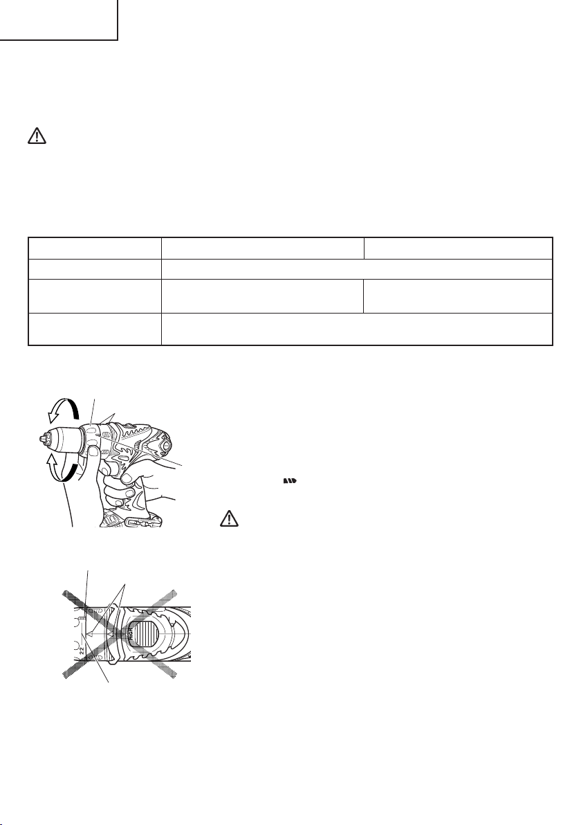
(2) Dismounting the bit
Loosen the sleeve by turning it toward the left (in the counterclockwise direction as
viewed from the front), and then take out the bit, etc. (See Fig. 18)
NOTE: If the sleeve is tightened in a state where the clip of the keyless chuck is opened to
a maximum limit, a click noise may occur. This is the noise that occurs when the
loosening of the keyless chuck is prevented and is not a malfunction.
CAUTION:
When mounting a bit into the keyless chuck, tighten firmly. If the sleeve is not tight,
the bit may slip or fall out, causing injury.
NOTE: Loosening stuck or hard to move sleeves.
Grasp the bit installed in the keyless chuck, in a vise or similar tool.
Set the cap position to “1-7” and turn the switch on. The motor then starts.
Finally, rotate the sleeve to the left, and it will loosen.
5. Automatic spindle-lock mechanism
This unit has automatic spindle-lock mechanism for quick bit changes.
6. Confirm that the battery is mounted correctly
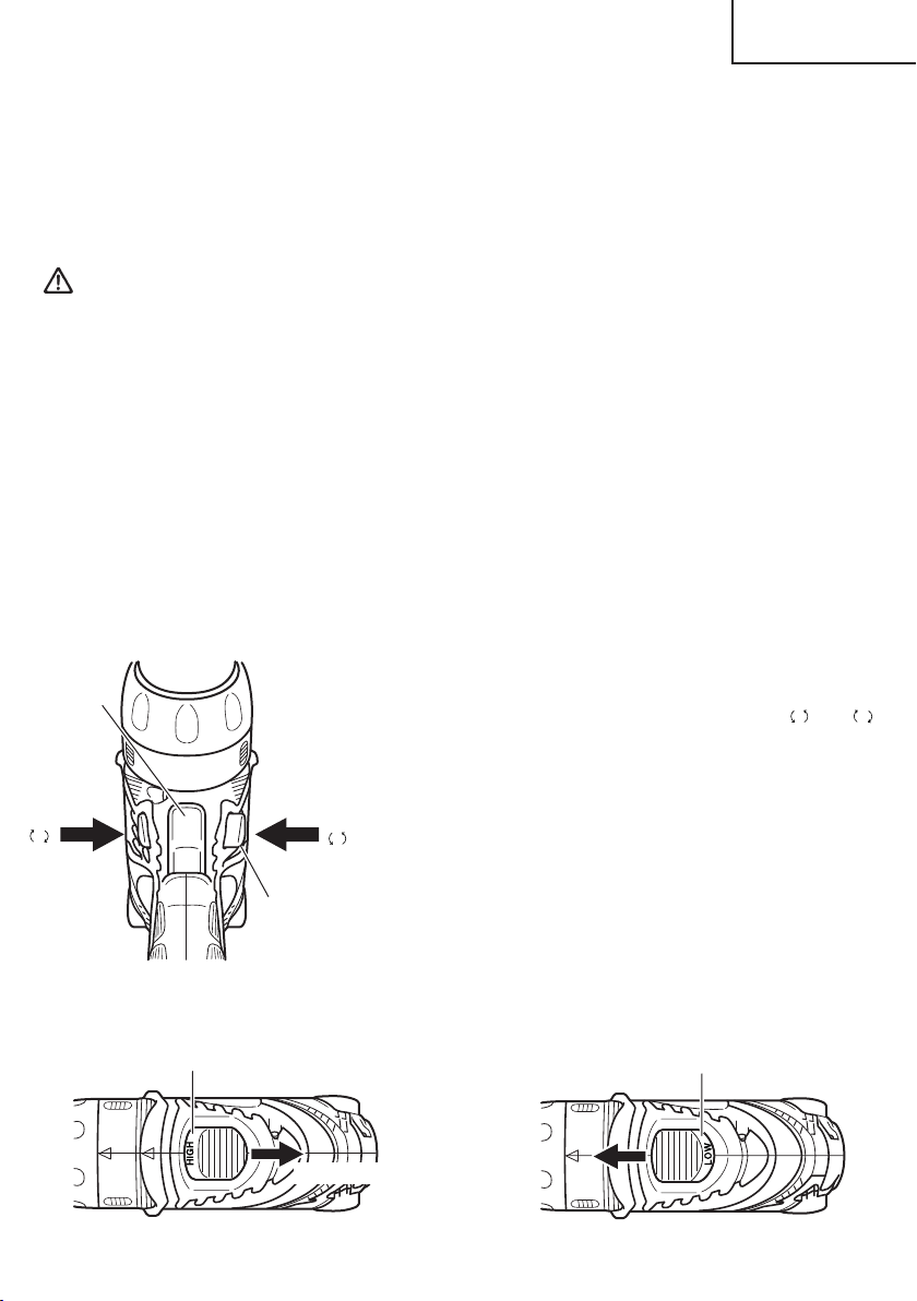
7. Check the rotational direction
The bit rotates clockwise (viewed from the rear side)
Trigger
switch
R
Selector
Button
by pushing the R-side of the selector button.
The L-side of the selector button is pushed to turn
the bit counterclockwise. (See Fig. 19) (The
L
marks are provided on the selector button.)
䡬 When the trigger switch is depressed, the tool rotates.
When the trigger is released, the tool stops.
䡬 The rotational speed of the drill can be controlled by
varying the amount that the trigger switch is pulled.
L
Speed is low when the trigger switch is pulled slightly
and increases as the trigger switch is pulled more.
䡬 When releasing the trigger of the switch, the brake
will be applied for immediate stopping.
and
R
Fig. 19
8. Change rotation speed
Shift knob
Fig. 20 Fig. 21
High speed
Shift knob
Low speed
23
Page 24
English
Operate the shift knob to change the rotational speed. Move the shift knob in the direction
of the arrow. (See Fig. 20 and 21)
When the shift knob is set to “LOW”, the drill rotates at a low speed. When set to
“HIGH”, the drill rotates at a high speed.
CAUTION:
● When changing the rotational speed with the shift knob, confirm that the switch is off.
Changing the speed while the motor is rotating will damage the gears.
● When a large force is required for operation (operations indicated in the following
chart) set the shift knob to “LOW”. If “HIGH” is set and the unit is used, it may cause
the motor to burn out or malfunction prematurely.
Model DS14DMR DS18DMR
Metal Drilling
Wood Drilling
Wood Screw
Tightening
When the diameter of the hole exceeds 5/16" (8 mm).
When the diameter of the hole
exceeds 15/16" (24 mm).
When the size of the wood screw exceeds 3/16" (4.8 mm)
diameter × 2" (50 mm).
When the diameter of the hole
exceeds 1-1/16" (27 mm).
9. Confirm the cap position (See Fig. 22)
Cap
Triangle mark
Drill
mark
The tightening torque of this unit can be adjusted
according to the cap position, at which the cap is set.
(1) When using this unit as a screwdriver, line up the one
of the numbers “1, 4, 7 ... 22” on the cap, or the black
dot, with the triangle mark on the outer body.
(2) When using this unit as a drill, line up the cap drill
mark “
” with the triangle mark on the outer body.
CAUTION:
Fig. 22
Drill mark
Triangle mark
Black line
Fig. 23
● The cap cannot be set between the numerals “1, 4, 7
... 22” or the black dot.
● Do not use with the cap numeral at “22” and the black
line at the middle of the drill mark. Doing so may cause
damage. (See Fig. 23)
10. Tightening torque adjustment
(1) Tightening torque
Tightening torque should correspond in its intensity to the screw diameter. When too
strong power is used, the screw head may be broken or be injured.
Be sure to adjust the cap position according to the screw diameter.
24
Page 25
English
(2) Tightening torque indication (See Fig. 22)
The tightening torque differs depending on the type of screw and the material being
tightened.
The unit indicates the tightening torque with the numbers “1, 4, 7 ... 22” on the cap, and
a black dot. The tightening torque at position “1” is the weakest and the torque is
strongest at the highest number.
(3) Adjusting the tightening torque (See Fig. 22)
Rotate the cap and line up the numbers “1, 4, 7 ... 22” on the cap, or the black dot, with
the triangle mark on the outer body. Adjust the cap in the weak or the strong torque
direction according to the torque you need.
CAUTION:
● The motor rotation may be locked to cease while the unit is used as drill. While operating
the driver drill, take care not to lock the motor.
● When setting the shift knob to “HIGH” (high speed) and the position of the cap is
between “16” and “22”, it may happen that the clutch does not engaged and that the
motor is locked. In such a case, please set the shift knob to “LOW” (low speed).
● If the motor is locked, immediately turn the power off. If the motor is locked for a
while, the motor or battery may be burnt.
● Too long hammering may cause the screw broken due to excessive tightening.
● A buzzing noise is produced when the motor is about to rotate; this is only a noise, not
a machine failure.
THE SCOPE AND SUGGESTIONS FOR USES
Table 6
Work Cap position Suggestions
Wood
Drilling Steel Use for drilling purpose.
Aluminum
Screw
tightening
Small
screw diameter.
Wood
screw
1 – 22
1 –
Use the bit and socket matching the screw
Use after drilling a pilot hole.
25
Page 26
English
HOW TO SELECT TIGHTENING TORQUE
Table 7
Cap
position
1 Approximately 18 in-lbs. (20 kg-cm)
4 Approximately 27 in-lbs. (31 kg-cm)
7 Approximately 37 in-lbs. (43 kg-cm)
10 Approximately 47 in-lbs. (54 kg-cm)
16 Approximately 67 in-lbs. (77 kg-cm)
22 Approximately 87 in-lbs. (100 kg-cm)
High speed: Approximately 106 in-lbs.
Low speed: Approximately 442 in-lbs.
NOTE:
The selected content shown in Table 7 indicates the differences according to screw
type, screw size and material used.
CAUTION:
● While operating the Cordless driver drill, take care not to lock the motor.
If the motor is locked, immediately turn the power off.
If the motor is locked for a while, the motor or battery will be burnt.
● Do not tighten too strongly as the screw heads will be damaged.
Tightening torque Operation example
Machine screw
tightening.
Screw tightening for
soft wood material.
Screw tightening for
hard wood material.
Approximately 124 in-lbs.
Approximately 510 in-lbs.
(122 kg-cm)(DS14DMR)
(143 kg-cm)(DS18DMR)
(550 kg-cm)(DS14DMR)
(633 kg-cm)(DS18DMR)
Thick screw tightening.
When used as a drill.
26
Page 27
English
MAINTENANCE AND INSPECTION
CAUTION: Pull out battery before doing any inspection or maintenance.
1. Checking the condition of the bit
The bits should be checked regularly. If worn or broken bits can slip or decrease the
efficiency of the motor and burn it out.
Replace worn bits with new ones.
CAUTION: If you use a driver bit of which point is worn or broken, it will be dangerous
since it slips. So replace it with a new one.
2. Check the Screws
Loose screws are dangerous. Regularly inspect them and make sure they are tight.
CAUTION: Using this power tool with loosened screws is extremely dangerous.
3. Maintenance of the motor
The motor unit winding is the very “heart” of the
power tool.
Exercise due care to ensure the winding does not
become damaged and/or wet with oil or water.
4. Inspecting the carbon brushes (Fig. 24)
The motor employs carbon brushes which are
consumable parts. Since and excessively worn
carbon brush can result in motor trouble, replace
the carbon brush with new ones when it becomes
worn to or near the “wear limit”. In addition,
always keep carbon brushes clean and ensure that
they slide freely within the brush holders.
NOTE:
When replacing the carbon brush with a new one,
be sure to use the Hitachi Carbon Brush Code No.
999054.
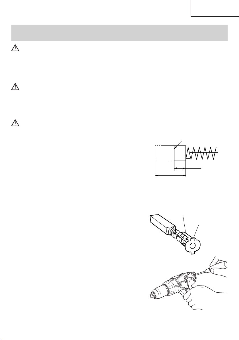
5. Replacing carbon brushes
Take out the carbon brush by first removing the
brush cap and then hooking the protrusion of the
carbon brush with a flat head screw driver, etc.,
as shown in Fig. 26.
When installing the carbon brush, choose the
direction so that the nail of the carbon brush
agrees with the contact portion outside the brush
tube. Then push it in with a finger as illustrated in
Fig. 27. Lastly, install the brush cap.
Wear limit
0.12" (3 mm)
0.45"
(11.5 mm)
Fig. 24
Nail of carbon brush
Protrusion
of carbon
brush
Fig. 25
Fig. 26
27
Page 28

English
CAUTION:
● Be absolutely sure to insert the nail of the carbon
brush into the contact portion outside the brush
tube. (You can insert whichever one of the two
nails provided.)
● Caution must be exercised since any error in this
operation can result in the deformed nail of the
carbon brush and may cause motor trouble at an
early stage.
Contact portion
outside brush tube
Fig. 27
6. Check for Dust
Dust may be removed with a soft cloth or a cloth dampened with soapy water.
Do not use bleach, chlorine, gasoline or thinner, for they may damage the plastics.
7. Disposal of the exhausted battery
WARNING: Do not dispose of the exhausted battery. The battery must explode if it
is incinerated. The product that you have purchased contains a
rechargeable battery. The battery is recyclable. At the end of it’s useful
life, under various state and local laws, it may be illegal to dispose of
this battery into the municipal waste stream. Check with your local
solid waste officials for details in your area for recycling options or
proper disposal.
8. Storage
Storing in a place below 104°F (40°C) and out of the reach of children.
9. Service and repairs
All quality power tools will eventually require servicing or replacement of parts because
of wear from normal use. To assure that only authorized replacement parts will be
used, all service and repairs must be performed by a HITACHI AUTHORIZED SERVICE
CENTER, ONLY.
28
Page 29

English
ACCESSORIES
WARNING: ALWAYS use Only authorized HITACHI replacement parts and
accessories. NEVER use replacement parts or accessories which are
not intended for use with this tool. Contact HITACHI if you are not sure
whether it is safe to use a particular replacement part or accessory
with your tool.
The use of any other attachment or accessory can be dangerous and
could cause injury or mechanical damage.
NOTE:
Accessories are subject to change without any obligation on the part of the HITACHI.
STANDARD ACCESSORIES
DS14DMR
(BFK)
DS18DMR
(HLCK)
1
1 Phillips bit (No. 2 × 65L) (Code No. 983006) ............. 1
2 Battery (EB14B) ........................................................... 2
3 Battery Charger (UC14YFA) ....................................... 1
4 Side handle (Code No. 323001) ................................. 1
5 Plastic Case ................................................................. 1
1
1 Phillips bit (No. 2 × 65L) (Code No. 983006) ............. 1
2 Battery (EB1830HL) ..................................................... 2
3 Battery Charger (UC24YJ) .......................................... 1
4 Side handle (Code No. 323001) ................................. 1
5
Plastic Case ....................................................................
2
Fig. 28
2
Fig. 29
3
3
4
4
5
5
1
29
Page 30

English
OPTIONAL ACCESSORIES.....sold separately
1. Battery (EB14B) 2. Battery (EB1830HL)
(For DS14DMR) (For DS18DMR)
Fig. 30 Fig. 31
NOTE:
Specifications are subject to change without any obligation on the part of the HITACHI.
30
Page 31

Français
INFORMATIONS IMPORTANTES DE SÉCURITÉ
Lire et comprendre toutes les précautions de sécurité, les avertissements et les instructions
de fonctionnement dans ce mode d’emploi avant d’utiliser ou d’entretenir cet outil motorisé.
La plupart des accidents causés lors de l’utilisation ou de l’entretien de l’outil motorisé
proviennent d’un non respect des règles ou précautions de base de sécurité. Un accident
peut la plupart du temps être évité si l’on reconnaît une situation de danger potentiel avant
qu’elle ne se produise, et en observant les procédures de sécurité appropriées.
Les précautions de base de sécurité sont mises en évidence dans la section “SECURITE”
de ce mode d’emploi et dans les sections qui contiennent les instructions de fonctionnement
et d’entretien.
Les dangers qui doivent être évités pour prévenir des blessures corporelles ou un
endommagement de la machine sont identifiés par AVERTISSEMENTS sur l’outil motorisé
et dans ce mode d’emploi.
NE JAMAIS utiliser cet outil motorisé d’une manière qui n’est pas spécifiquement
recommandée par HITACHI.
SIGNIFICATION DES MOTS D’AVERTISSEMENT
AVERTISSEMENT indique des situations potentiellement dangereuses qui, si elles sont
ignorées, pourraient entraîner la mort ou de sérieuses blessures.
ATTENTION indique des situations dangereuses potentilles qui, si elles ne sont pas évitées,
peuvent entraîner de mineures et légères blessures ou endommager la machine.
REMARQUE met en relief des informations essentielles.
31
Page 32

Français
SECURITE
REGLES GENERALE DE SECURITE – POUR TOUS
LES OUTILS FONCTIONNANT SUR BATTERIE
AVERTISSEMENT : Lire et coxmprendre toutes les instructions.
Un non respect de toutes les instructions ci-dessous peut
entraîner une électrocution, un incendie et/ou de sérieuses
blessures personnelles.
CONSERVER CES INSTRUCTIONS
1. Zone de travail
(1) Garder la zone de travail propre et bien éclairée. Les établis mal rangés et les
zones sombres invitent aux accidents.
(2) Ne pas utiliser les outils motorisés dans une atmosphère explosive, telle qu’en
présence de liquides inflammables, de gaz ou de poussières. Les outils motorisés
créent des étincelles qui risquent d’enflammer la poussière ou les vapeurs.
(3) Tenir les spectateurs, les enfants et les visiteurs éloignés, lors de l’utilisation de
l’outil motorisé. Une distraction peut faire perdre le contrôle de la machine.
2. Sécurité électrique
(1) Un outil motorisé à batterie avec batterie intégrée ou batterie séparée ne devra
être rechargé qu’avec le chargeur spécialement conçu pour la batterie.
Un chargeur qui convient pour un type de batterie donné peut présenter un risque
de feu s’il est utilisé avec une autre batterie.
(2) Utiliser l’outil motorisé à batterie exclusivement avec la batterie spécialement
conçue.
3. Sécurité personnelle
32
L’utilisation de toute autre batterie peut présenter un risque de feu.
(1) Rester sur ses gardes, regarder ce que l’on fait et utiliser son sens commun lors de
l’utilisation d’un outil motorisé. Ne pas utiliser un outil en état de fatigue ou sous
l’influence de drogues, d’alcool ou de médicaments. Un moment d’inattention lors
de l’utilisation de l’outil motorisé peut entraîner de sérieuses blessures personnelles.
(2) S’habiller correctement. Ne pas porter des vêtements larges ou des bijoux. Attacher
les cheveux longs. Tenir ses cheveux, vêtements et ses gants éloignés des parties
mobiles. Les vêtements larges, les bijoux et les cheveux longs peuvent se prendre
dans les parties mobiles.
(3) Eviter tout démarrage accidentel. S’assurer que le l’interrupteur d’alimentation
est sur la position d’arrêt avant d’insérer la batterie. Transporter l’appareil avec
les doigts sur l’interrupteur d’alimentation ou la batterie insérée dan un outil avec
l’interrupteur sur la position marche invite aux accidents.
(4) Retirer les clefs d’ajustement ou les commutateurs avant de mettre l’outil sous
tension. Une clef qui est laissée attachée à une partie tournante de l’outil peut
provoquer une blessure personnelle.
(5) Ne pas trop présumer de ses forces. Garder en permanence une position et un
équilibre correct. Une position et un équilibre correct permettent un meilleur contrôle
de l’outil dans des situations inattendues.
(6) Utiliser un équipement de sécurité. Toujours porter des lunettes de protection. Un
masque à poussière, des chaussures de sécurité antidérapantes, un chapeau dur
et des bouchons d’oreille doivent être utilisés dans les conditions appropriées.
Page 33

Français
4. Utilisation de l’outil et entretien
(1) Utiliser un étau ou toutes autres façons de fixer et maintenir la pièce à usiner sur
une plate-forme stable. Tenir la pièce avec la main ou contre son corps est instable
et peut conduire à une perte de contrôle de l’outil.
(2) Ne pas forcer sur l’outil. Utiliser l’outil correct pour l’application souhaitée. L’outil
correct réalisera un meilleur et plus sûr travail dans le domaine pour lequel il a été
conçu.
(3) Ne pas utiliser un outil s’il ne se met pas sous ou hors tension avec un interrupteur.
Un outil qui ne peut pas être commandé avec un interrupteur est dangereux et doit
être réparé.
(4) Débrancher la batterie de l’outil ou mettre l’interrupteur sur la position verrouillée
ou éteinte avant d’effectuer un réglage, de remplacer un accessoire ou de ranger
l’outil. Ces mesures de sécurité préventives réduiront les risques de déclenchement
accidental de l’outil.
(5) Ranger les outils inutilisés hors de la portée des enfants et des autres personnes
inexpérimentées. Les outils sont dangereux dans les mains de personnes
inexpérimentées.
(6) Lorsqu’on ne se sert pas de la batterie, l’éloigner des objets métalliques, par
exemple trombones, pièces de monnaie, clous, vis, ou petits objets métalliques
qui peuvent créer une connexion entre deux bornes.
Le fait de court-circuiter les bornes entre elles peut provoquer des étincelles, des
brulûres ou un feu.
(7) Conserver les outils avec soin. Garder les outils de coupe aiguisés et propres. Des
outils bien entretenus, avec des lames coupantes aiguisées risquent moins de se
gripper et sont plus faciles à contrôler.
(8) Vérifier les défauts d’alignement ou grippage des parties mobiles, les ruptures
des pièces et toutes les autres conditions qui peuvent affecter le fonctionnement
des outils. En cas de dommage, faire réparer l’outil avant de l’utiliser. Beaucoup
d’accidents sont causés par des outils mal entretenus.
(9) Utiliser uniquement les accessoires recommandés par le fabricant pour le modèle
utilisé. Des accessoires qui peuvent convenir à un outil, peuvent devenir dangereux
5. Réparation
lorsqu’ils sont utilisés avec un autre outil.
(1) La réparation de l’outil ne doit être réalisée uniquement par un réparateur qualifié.
Une réparation ou un entretien réalisé par un personnel non qualifié peut entraîner
des risques de blessures.
(2) Lors de la réparation d’un outil, utiliser uniquement des pièces de rechange
identiques. Suivre les instructions de la section d’entretien de ce mode d’emploi.
L’utilisation de pièces non autorisées ou un non respect des instructions d’entretien
peut créer un risque d’électrocution ou de blessures.
AVERTISSEMENT :
La poussière résultant d’un ponçage, d’un sciage, d’un meulage, d’un perçage ou de
toute autre activité de construction renferme des produits chimiques qui sont connus par
l’Etat de Californie pour causer des cancers, des défauts de naissance et autres anomalies
de reproduction. Nous énumérons ci-dessus certains de ces produits chimiques :
● Plomb des peintres à base de plomb,
● Silice cristalline des briques et du ciment et autres matériaux de maçonnerie, et
● Arsenic et chrome du bois d’oeuvre traité chimiquement.
Le risque d’exposition à ces substances varie en fonction de la fréquence d’exécution de
ce genre de travail. Pour réduire l’exposition à ces produits chimiques, travailier dans un
lieu bien ventilé, et porter un équipement de protection agréé, par exemple un masque
anti-poussière spécialement conçu pour filter les particules microscopiques.
33
Page 34

Français
REGLES DE SECURITE SPECIFIQUES ET SYMBOLES
1. Tenir les outils par les surfaces de grippage lors de la réalisation d’opération où l’outil
de coupe risque d’entrer en contact avec des câbles cachés ou son propre cordon. Un
contact avec un fil “sous tension” mettra les parties métalliques de l’outil “sous tension”
et électrocutera l’utilisateur.
2. TOUJOURS porter des bouchons d’oreille lors de l’utilisation de l’outil pendant de
longues périodes.
Une exposition prolongée à un son de forte intensité peut endommager
l’ouïe de l’utilisateur.
3. NE JAMAIS approcher les mains ni aucune autre partie du corps de la mèche ou du
mandrin pendant le travail. Tenir la perceuse uniquement par sa poignée.
4. La perceuse-visseuse fonctionant sans fil, bien avoir conscience qu’elle est constamment
prête à fonctionner.
5. Lors d’un travail en position élevée, évacuer tout le monde de l’aire de travail et ne pas
oublier qu’on travaille en hauteur.
6. NE JAMAIS toucher les parties mobiles.
NE JAMAIS placer ses mains, ses doigts ou toute autre partie de son corps près des
parties mobiles de l’outil.
7. NE JAMAIS utiliser l’outil sans que tous les dispositifs de sécurité ne soient en place.
NE JAMAIS faire fonctionner cet outil sans que tous les dispositifs et caractéristiques
de sécurité ne soient en place et en état de fonctionnement. Si un entretien ou une
réparation nécessite le retrait d’un dispositif ou d’une caractéristique de sécurité,
s’assurer de bien remettre en place le dispositif ou la caractéristique de sécurité avant
de recommencer à utiliser l’outil.
8. Utiliser l’outil correct.
Ne pas forcer sur un petit outil ou accessoire pour faire le travail d’un outil de grande
puissance.
Ne pas utiliser un outil pour un usage pour lequel il n’a pas été prévu : par exemple, ne
pas utiliser une scie circulaire pour couper des branches d’arbre ou des bûches.
9. NE JAMAIS utiliser un outil motorisé pour des applications autres que celles spécifiées.
NE JAMAIS utiliser un outil motorisé pour des applications autres que celles spécifiées
dans le mode d’emploi.
10. Manipuler l’outil correctement.
Utiliser l’outil de la façon indiquée dans ce mode d’emploi. Ne pas laisser tomber ou
lancer l’outil. NE JAMAIS permettre que l’outil soit utilisé par des enfants, des personnes
non familiarisées avec son fonctionnement ou un personnel non autorisé.
11. Maintenir toutes les vis, tous les boulons et les couvercles fermement en place.
Maintenir toutes les vis, tous les boulons et les couvercles fermement montés. Vérifier
leurs conditions périodiquement.
34
Page 35
Français
12. Ne pas utiliser les outils motorisés si le revêtement de plastique ou la poignée est
fendu.
Des fentes dans le revêtement ou la poignée peuvent entraîner une électrocution. De
tels outils ne doivent pas être utilisés avant d’être réparé.
13. Les lames et les accessoires doivent être fermement montés sur l’outil.
Eviter les blessures potentielles personnelles et aux autres. Les lames, les instruments
de coupe et les accessoires qui ont été montés sur l’outil doivent être fixés et serrés
fermement.
14. NE JAMAIS utiliser un outil défectueux ou qui fonctionne anormalement.
Si l’outil n’a pas l’air de fonctionner normalement, fait des bruits étranges ou sans cela
paraît défectueux, arrêter de l’utiliser immédiatement et le faire réparer par un centre
de service Hitachi autorisé.
15. Manipuler l’outil motorisé avec précaution.
Si un outil motorisé tombe ou frappe un matériau dur accidentellement, il risque d’être
déformé, fendu ou endommagé.
16. Ne pas essuyer les parties en plastique avec du solvant.
Les solvants comme l’essence, les diluants, la benzine, le tétrachlorure de carbone et
l’alcool peuvent endommager et fissurer les parties en plastique. Ne pas les essuyer
avec de tels solvants.
Essuyer les parties en plastique avec un chiffon doux légèrement imbibé d’une solution
d’eau savonneuse et sécher minutieusement.
17. TOUJOURS porter des lunettes de protection qui respectent les dernières révisions du
Standard ANSI Z87.1.
18. Définitions pour les symboles utilisés sur cet outil
............
V
—
---
no
---/min
volts
...........
courant continu
..........
vitesse sans charge
...
tours par minute
35
Page 36

Français
CONSIGNES DE SÉCURITÉ IMPORTANTES
POUR LE CHARGEUR DE BATTERIE
1. Ce manuel renferme des consignes de sécurité et d’utilisation importantes pour le
chargeur de batterie modèle UC14YFA/UC24YJ.
2. Avant d’utiliser le chargeur de batterie, lire toutes les étiquettes d’instruction et de
précaution apposées sur (1) le chargeur de batterie, (2) la batterie, et (3) le produit
utilisant la batterie.
3. Pour réduire tout risque de blessure, ne recharger que les batteries rechargeables
HITACHI utilisées dans le modèle series EB7, EB9, EB12, EB14, EB18 et EB24B. Les
autres types de batterie pourraient exploser et provoquer des blessures ou des
dommages.
4. Ne pas exposer le chargeur à la pluie ni à la neige.
5. L’utilisation d’un accessoire non recommandé ou non vendu par le fabricant du chargeur
de batterie risque de provoquer un feu, une décharge électrique ou des blessures.
6. Pour réduire tout risque de dommage de la fiche et du cordon électrique, débrancher le
cordon du chargeur en tirant sur la fiche.
7. Vérifier que le cordon est placé de façon que personne ne puisse marcher dessus, se
prendre les pieds dedans, ni l’endommager ou le soumettre à des contraintes.
8. Ne pas utiliser de cordon de rallonge si cela n’est pas absolument nécessaire. L’utilisation
d’un cordon de rallonge incorrect pourrait entraîner un feu ou une décharge électrique.
Si l’on doit utiliser un cordon de rallonge, s’assurer que :
a. Les broches de la rallonge ont les mêmes numéro, taille et forme que celles de la
fiche du chargeur ;
b. Le cordon de rallonge est correctement raccordé et en bon état électrique ;
c. Le calibre du fil doit être au moins suffisant pour l’intensité nominale CA (ampères)
du chargeur de batterie spécifiées dans le tableau ci-dessous.
Tableau 1
CALIBRE MINIMUM RECOMMANDÉ POUR LES CORDONS DE RALLONGE
DES CHARGEURS DE BATTERIE
Intensité nominale d’entrée CA (ampères)*
Egal ou mais non Longueur de cordon en pieds (mètres)
supérieur à inférieur à 25 (7,5) 50 (15) 100 (30) 150 (45)
0 2 18 18 18 16
2 3 18 18 16 14
3 4 18 18 16 14
* Si l’intensité nominale d’entrée du chargeur de batterie est donnée en watts et non en
ampères, calculer la capacité en ampères correspondante en divisant la capacité en
ampères par la capacité de tension, par exemple :
1250 watts
125 volts
36
= 10 ampères
Calibre du cordon
Page 37

Français
9. Ne pas utiliser le chargeur si son cordon ou sa fiche sont endommagés - Le remplacer
immédiatement.
10. Ne pas utiliser le chargeur s’il a reçu un coup, s’il est tombé ou endommagé de toute
autre manière. L’apporter à un réparateur qualifié.
11. Ne pas démonter le chargeur ni le produit qui reçoit la batterie ; si un entretien ou des
réparations sont nécessaires, les apporter à un réparateur qualifié. Un remontage
incorrect pourrait provoquer une décharge électrique ou un feu.
12. Pour réduire tout risque de décharge électrique, débrancher le chargeur de la prise
secteur avant tout entretien ou nettoyage. Il ne suffit pas de sortir la batterie.
CONSIGNES DE SÉCURITÉ IMPORTANTES POUR L’UTILISATION
DE LA BATTERIE ET DU CHARGEUR DE BATTERIE
Pour pouvoir utiliser la perceuse-visseuse sans fil, il faudra recharger la batterie. Avant
d’utiliser le chargeur de batterie modèle UC14YFA/UC24YJ, bien lire attentivement toutes
les consignes et les avertissements signalés sur le chargeur, sur la batterie ou dans ce
manuel.
BIEN NOTER : UTILISER EXCLUSIVEMENT DES BATTERIES HITACHI DES SERIES EB7,
EB9, EB12, EB14, EB18 ET EB24B. LES AUTRES TYPES DE BATTERIE POURRAIENT
EXPLOSER OU PROVOQUER DES BLESSURES !
Pour éviter tout risque de blessure, observer les consignes suivantes :
AVERTISSEMENT : Une utilisation incorrecte de la batterie ou du chargeur de
batterie risque de provoquer des blessures. Pour éviter tout
risque de blessure :
1. NE JAMAIS démonter la batterie.
2. NE JAMAIS jeter la batterie au feu, même si elle est endommagée ou complètement
usée. La batterie risque d’exploser au feu.
3. NE JAMAIS court-circuiter la batterie.
4. NE JAMAIS insérer d’objets dans les ouïes d’aération du chargeur. Il pourrait en
résulter un choc électrique ou des dommages du chargeur.
5. NE JAMAIS effectuer la recharge à l’extérieur. Eloigner la batterie des rayons directs
du soleil et utiliser exclusivement dans des endroits à faible humidité et
bien aérés.
6. NE JAMAIS effectuer la recharge si la température est inférieure à 0°C (32°F) ou
supérieure à 40°C (104°F).
7. NE JAMAIS raccorder deux chargeurs de batterie ensemble.
8. NE JAMAIS insérer de corps étrangers dans l’orifice de la batterie ou du chargeur de
batterie.
9. NE JAMAIS utiliser de transformateur-élévateur pour la recharge.
10. NE JAMAIS utiliser de générateur de moteur ni d’alimentation CC pour la recharge.
11. NE JAMAIS ranger la batterie ni le chargeur de batterie dans un lieu où la température
peut atteindre ou dépasser 40°C (104°F).
12. TOUJOURS alimenter le chargeur sur une prise secteur domestique standard (120
volts). L’utilisation du chargeur à une autre tension peut entraîner une
surchauffe et endommager le chargeur.
37
Page 38

Français
13. TOUJOURS attendre au moins 15 minutes entre deux recharges pour éviter toute
surchauffe du chargeur.
14. TOUJOURS débrancher le cordon d’alimentation de la prise secteur lorsqu’on ne se
sert pas du chargeur.
MISE AU REBUT D’UNE BATTERIE USÉE
AVERTISSEMENT : Ne pas jeter la batterie usée aux ordures ménagères. La
batterie risque d’exploser si elle est incinérée. L’appareil que
vous avez acheté renferme une batterie rechargeable. La
batterie est recyclable. Lorsqu’elle a atteint sa limite de
service, selon les lois des états et les lois locales, il peut être
illégal de jeter cette batterie aux ordures ménagères. Vérifier
auprès de son service de ramassage d’ordures les options
de recyclage et la procédure correcte de mise au rebut.
CONSERVER CES INSTRUCTIONS
ET
LES METTRE A LA DISPOSITION
DES AUTRES UTILISATEURS
ET
PROPRIETAIRES DE CET OUTIL !
38
Page 39

Français
DESCRIPTION FONCTIONNELLE
REMARQUE :
Les informations contenues dans ce mode d’emploi sont conçues pour assister
l’utilisateur dans une utilisation sans danger et un entretien de l’outil motorisé.
NE JAMAIS utiliser ni entreprendre une révision de l’outil sans avoir d’abord lu et
compris toutes les instructions de sécurité contenues dans ce manuel.
Certaines illustrations dans ce mode d’emploi peuvent montrer des détails ou des
accessoires différents de ceux de l’outil motorisé utilisé.
MODELE
DS14DMR (BFK) : avec chargeur (UC14YFA) et coffret
DS18DMR (HLCK) : avec chargeur (UC24YJ) et coffret
NOM DES PARTIES
1. Perceuse-visseuse à batterie (DS14DMR et DS18DMR)
<DS14DMR>
Mandrin sans
clavette
Capot
Bouton de décalage
Plaque
signalétique
Bouton-poussoir
Déclencheur
Poignée
Porte-foret
Poignée latérale
Batterie
Bouton-poussoir
39
Page 40

Français
<DS18DMR>
Mandrin sans
clavette
Capot
Bouton de décalage
Plaque signalétique
Bouton-poussoir
Déclencheur
Poignée
Porte-foret
䡬 Batterie (EB14B)
(Pour DS14DMR)
Taquet
2. Chargeur de batterie
<UC14YFA pour DS14DMR>
Poignée latérale
Batterie
Orifice de prise
Plaque
signalétique
䡬 Batterie (EB1830HL)
(Pour DS18DMR)
Orifice de prise
Taquet
Fig. 1
Bouton-poussoir
Plaque
signalétique
Lampe témoin
Plaque de précaution
Plaque signalétique
40
Orifice d’installation de la batterie
Fig. 2
Page 41
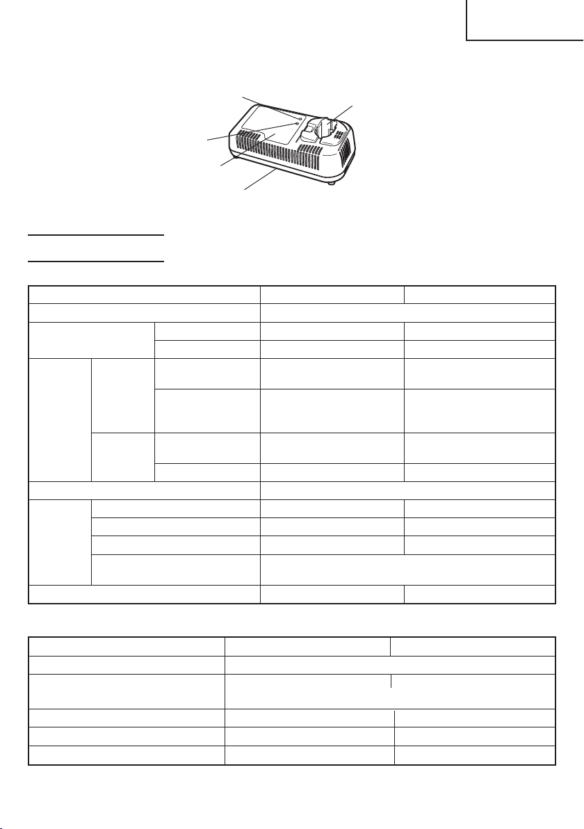
<UC24YJ pour DS18DMR>
Français
Voyant de temps
de charge
Voyant d’état
de charge
Plaque de
précaution
Plaque
Signalétique
Fig. 3
Orifice d’installation
de la batterie
SPECIFICATIONS
1. Perceuse-visseuse à batterie
Modèle DS14DMR DS18DMR
Moteur Moteur CC
Vitesse à vide Faible 0–400/min 0–400/min
Elevée0–1500/min 0–1600/min
Capacité Perçage Bois (Epaisseur
11/16" (18 mm)) (Bois tendre) (Bois tendre)
Métal (Epaisseur 1/2" (13 mm) 1/2" (13 mm)
1/16" (1,6 mm)) (Acier tendre (Acier tendre
Vissage Vis en bois #20 × 3" #20 × 4"
Petite vis 1/4" (6 mm) 1/4" (6 mm)
Capacité de mandrin Diamètre de serrage maximum 1/2" (13 mm)
Batterie Modèle EB14B EB1830HL
Type
Tension CC 14,4 V CC 18 V
Fréquence de recharge et
de décharge
Poids 5,1 lbs. (2,3 kg) 5,5 lbs. (2,5 kg)
1–3/4" (44 mm)
ou Aluminium) ou Aluminium)
(8 mm × 75 mm) (8 mm × 100 mm)
Batterie au nickel-cadmium
environ 1000
2" (50 mm)
Batterie à l'hydrure métallique de nickel
2. Chargeur de batterie
Modèle UC14YFA UC24YJ
Source d’alimentation d’entrée Monophasée : CA 120 V 60 Hz
Durée de recharge Environ 50 min. Environ 28 min.
(À une température de 68°F (20°C))
Tension de charge CC 7,2–14,4 V CC 7,2–24 V
Courant de charge CC 2,6 A CC 7,5 A
Poids 1,3 lbs. (0,6 kg) 2,2 lbs. (1,0 kg)
REMARQUE : La durée de recharge peut varier en fonction de la température et de la tension
de la source d’alimentation.
41
Page 42

Français
ASSEMBLAGE ET FONCTIONNEMENT
UTILISATIONS
䡬 Utilisation comme mèche
Perçage d’acier doux, de bois, de plastique et d’aluminium
䡬 Utilisation comme tournevis
Serrage et desserrage de vis à métaux, vis en bois et vis auto-taraudeuses
MÉTHODE DE RETRAIT ET D’INSTALLATION DE LA BATTERIE
䡬 Installation de la batterie
Aligner la batterie sur la fente de la poignée de l’outil et la glisser à l’intérieur.
Toujours insérer la batterie à fond, jusqu’à ce qu’elle se bloque avec un petit déclic.
Sinon, elle risque de tomber accidentellement de l’outil et de blesser l’opérateur ou
d’autres personnes alentour. (Fig. 4)
䡬 Retrait de la batterie
Sortir la batterie de la poignée de l’outil tout en appuyant sur les taquets (2) de chaque
côté de la batterie. (Fig. 4)
Déclencheur
Insérer
Tirer vers
l’extérieur
Fig. 4
Poignée
Taquet
Batterie
Pousser
MÉTHODE DE RECHARGE
Nous donnons ci-dessous une explication des méthodes de charge lors de l’utilisation du
chargeur de batterie UC14YFA ou UC24YJ. Pour effectuer la recharge avec le multi-chargeur
ET18DM, lire le mode d’emploi séparé de l’ET18DM.
REMARQUE :
Avant de brancher le chargeur dans la prise, vérifier les points suivants.
䡬 La tension de la source d’alimentation est indiquée sur la plaque signalétique.
䡬 Le cordon n’est pas endommagé.
AVERTISSEMENT : Ne pas effectuer de recharge à une tension supérieure à la
tension indiquée sur la plaque signalétique. Si la recharge
est effectuée à une tension supérieure à celle indiquée sur la
42
plaque signalétique, le chargeur brûlera.
Page 43

Français
Batterie
<UC14YFA>
1. Brancher la fiche du chargeur de batterie dans la
prise.
Quand la fiche du chargeur de batterie est branchée dans
la prise, le voyant de recharge clignote lentement en
Lampe
témoin
Fig. 5
rouge. (A intervalles d’une seconde)
AVERTISSEMENT :
Ne pas utiliser le cordon électrique
s’il est endommagé. Le faire réparer
immédiatement.
2. Insérer la batterie dans le chargeur de batterie.
Insérer la batterie dans le chargeur de batterie comme indiqué à la Fig. 5. Bien s’assurer
qu’elle touche le fond du chargeur de batterie.
3. Recharge
Quand la batterie est raccordée au chargeur de batterie, la recharge commence et la
lampe témoin s’allume en rouge. (Voir le Tableau 2)
REMARQUE :
Si la lampe témoin scintille en rouge, débrancher la fiche de la prise et vérifier si la
batterie est insérée correctement.
Quand la batterie est rechargée à fond, la lampe témoin clignote lentement en rouge.
(A intervalles d’une seconde) (Voir le Tableau 2)
(1) Indication de la lampe témoin
Les indications de la lampe témoin sont expliquées dans le Tableau 2, selon la condition
du chargeur ou de la batterie rechargeable.
43
Page 44

Français
Avant la
recharge
Clignote
(ROUGE)
Tableau 2
Indications de la lampe témoin
S’allume pendant 0,5 seconde. Ne
s’allume pas pendant 0,5 seconde.
(Eteint pendant 0,5 seconde)
Pendant la
recharge
Recharge
terminée
Recharge
impossible
Recharge
impossible
S’allume
(ROUGE)
Clignote
(ROUGE)
Scintille
(ROUGE)
S’allume
(VERTE)
S’allume sans interruption
S’allume pendant 0,5 seconde. Ne
s’allume pas pendant 0,5 seconde.
(Eteint pendant 0,5 seconde)
S’allume pendant 0,1 seconde. Ne
s’allume pas pendant 0,1 seconde.
(Eteint pendant 0,1 seconde)
S’allume sans interruption
Anomalie de la batterie ou du
chargeur
La température de la batterie est
élevé e et la recharge est
impossible.
(2) Température admissible d’une batterie rechargeable
La température admissible des batteries rechargeables est indiquée dans le tableau cidessous, et les batteries qui ont chauffé devront être laissées à refroidir pendant quelque
temps avant de pouvoir être rechargées.
Tableau 3 Recharge de batteries qui ont chauffé
Batteries rechargeables Température à laquelle la batterie peut être rechargée
EB14B 23°F—140°F (–5°C—60°C)
4. Débrancher le chargeur de batterie de la prise.
ATTENTION :
Ne pas débrancher la fiche de la prise en tirant sur le cordon.
Pour éviter tout dommage lorsqu’on débranche la fiche de la prise, bien tenir la fiche
proprement dite.
5. Retirer la batterie du chargeur de batterie.
Sortir la batterie du chargeur tout en la soutenant de la main.
ATTENTION :
● Si le chargeur a fonctionné pendant longtemps de suite, il sera chaud, ce qui risque de
provoquer des pannes. Lorsque la recharge est terminée, laisser le chargeur refroidir
pendant environ 15 secondes avant de passer à la recharge suivante.
● Si l’on recharge la batterie lorsqu’elle est chaude, soit parce qu’elle vient de fonctionner,
soit parce qu’elle est en plein soleil, il se peut que la lampe témoin s’allume en vert.
La batterie ne se rechargera pas. Dans ce cas, laisser la batterie refroidir avant de la
recharger.
44
Page 45

Français
● Si la lampe témoin scintille en rouge (à intervalles de 0,2 seconde), vérifier s’il y a des
corps étrangers dans l’orifice d’installation de la batterie du chargeur, et les enlever le
cas échéant. S’il n’y a pas de corps étrangers, il s’agit probablement d’une anomalie
de la batterie ou du chargeur. Les porter au service après-vente agréé.
En ce qui concerne le courant de décharge d’une batterie neuve
Etant donnée que les substances chimiques internes sont restées inactives dans le cas
des batteries neuves ou des batteries qui sont restées longtemps inutilisées, le courant
de décharge risque d’être très faible lors des première et deuxième utilisations. Ce
phénomène est temporaire et le temps de recharge normal sera rétabli quand les
batteries auront été rechargées 2 ou 3 fois.
Comment prolonger la durée de vie des batteries
(1) Recharger les batteries avant qu’elles ne soient complètement épuisées.
Quand la puissance de l’outil utilisé faiblit, l’éteindre et recharger la batterie. Si l’outil
continue d’être utilisé jusqu’à épuisement du courant électrique, la batterie risque d’être
endommagée et sa durée de vie se raccourcira.
(2) Eviter d’effectuer la recharge sous des températures élevées.
Une batterie est toujours chaude immédiatement après son utilisation. Si la batterie
est rechargée immédiatement après utilisation, les substances chimiques internes
risquent de se détériorer et la durée de vie de la batterie se raccourcira. Laisser la
batterie refroidir un moment avant de l’utiliser.
Battery
<UC24YJ>
1. Brancher la fiche du chargeur de batterie dans la
prise.
Voyant de
temps de
charge
Voyant
d’état de
charge
Lorsque la fiche du chargeur de batterie est insérée dans
la prise, le voyant d’état de charge clignote en rouge. (A
intervalles d’une seconde)
AVERTISSEMENT :
Ne pas utiliser le cordon électrique
s’il est endommagé. Le faire réparer
immédiatement.
Fig. 6
2. Insérer la batterie dans le chargeur de batterie.
Insérer la batterie dans le chargeur de batterie comme indiqué à la Fig. 6. Bien s’assurer
qu’elle touche le fond du chargeur de batterie.
3. Recharge
Lorsque la batterie est raccordée au chargeur de batterie, la recharge commence, et le
voyant de temps de recharge s’allume en rouge, en orange ou en vert selon le temps
de charge restant. (Voir le Tableau 4)
45
Page 46

Français
(1) Indications des témoins
Ce chargeur est muni d’un témoin de durée de charge qui indique la durée de charge
restante et d’un témoin d’état de charge qui indique l’état de la batterie comme montré
dans le Tableau 4.
(a) Durée de charge
Après le début de la charge, le témoin de durée de charge s’allume en rouge
indiquant 30 minutes, en orange indiquant 20 minutes et en vert indiquant 5 minutes,
jusqu’à ce que la charge soit terminée. Quand la batterie est complètement chargée,
le témoin d’état de charge s’allume en vert et le vibreur sonore sonne de façon
continue pendant 6 secondes.
(b) Attente en cas de surchauffe
Si la batterie est surchauffée, elle ne peut pas être chargée et le témoin de durée de
charge clignote en rouge (par intervalle de 0,6 seconde). Laissez la batterie en place,
insérée dans le chargeur, et la charge commencera quand la batterie aura refroidi.
(c) Charge impossible
En cas de mauvais fonctionnement de la batterie ou du chargeur, le témoin d’état
de charge clignote en orange rapidement (par intervalle de 0,2 seconde), et le vibreur
sonore sonne de façon intermittente pendant 5 secondes.
Tableau 4 Indications des témoins
Indications des témoins Témoin d’état
Durée de charge S’allume S’allume en continu 30 minutes jusqu’à la fin de la
Témoin
de
durée
de
charge
(rouge/
orange/
vert)
Témoin
d’état
de
charge
(rouge/
orange/
vert)
30 minutes en rouge charge.
Durée de charge S’allume S’allume en continu 20 minutes jusqu’à la fin de la
20 minutes en orange charge.
Durée de charge S’allume S’allume en continu 5 minutes jusqu’à la fin de la
5 minutes en vert charge.
Attente en cas
de surchauffe
Avant la charge
Charge terminée
Charge impossible
Clignote
en rouge (La charge commence quand la
Clignote
en rouge
S’allume S’allume en continu
en vert
Clignote
en orange
S’allume pendant 0,3 seconde,
s’éteint pendant 0,3 seconde
S’allume pendant 0,5 seconde,
s’éteint pendant 0,5 seconde
S’allume pendant 0,1 seconde,
s’éteint pendant 0,1 seconde
■■■■■■■■■■■
La batterie est surchauffée. éteint
Impossible à charger.
batterie a refroidi.)
Le cordon d’alimentation est
connecté à la prise secteur.
Mauvais fonctionnement de la
batterie ou du chargeur.
(2) Température admissible d’une batterie rechargeable
La température admissible des batteries rechargeables est indiquée dans le tableau cidessous, et les batteries qui ont chauffé devront être laissées à refroidir pendant quelque
temps avant de pouvoir être rechargées.
Tableau 5 Recharge de batteries qui ont chauffé
Batteries rechargeables Température à laquelle la batterie peut être rechargée
EB1830HL 32°F—122°F (0°C—50°C)
46
Page 47

Français
4. Débrancher le chargeur de batterie de la prise.
ATTENTION :
Ne pas débrancher la fiche de la prise en tirant sur le cordon.
Pour éviter tout dommage lorsqu’on débranche la fiche de la prise, bien tenir la fiche
proprement dite.
5. Retirer la batterie du chargeur de batterie.
Sortir la batterie du chargeur tout en la soutenant de la main.
ATTENTION :
● Une réparation est nécessaire si la prise secteur n’est pas correctement protégée ou si
le cordon d’alimentation ne reste pas dans la prise. Consultez votre électricien. Utiliser
le chargeur dans ces conditions peut entraîner un incendie.
● Si le voyant d’état de charge clignote rapidement (par intervalles de 0,2 seconde) et
que l’avertisseur sonore retentit par intermittence pendant 5 secondes, vérifier si l’orifice
de raccordement de la batterie n’est pas obstrué. Retirer les obstructions. Si vous ne
trouvez aucune obstruction, la batterie ou le chargeur peut mal fonctionner. Ramener
les à l’endroit où vous les avez achetés.
● Si le témoin de durée de charge ne s’allume pas quand le cordon d’alimentation est
connecté à la prise secteur, déconnectez le cordon d’alimentation et vérifiez si la batterie
est fixée correctement.
● La batterie retient la chaleur quand elle est utilisée ou laissée pendant une période
prolongée au soleil. Dans cet état, le témoin de durée de charge clignote en rouge et la
batterie ne peut pas être chargée immédiatement. Laissez la batterie insérée dans le
chargeur et la charge commence quand la batterie a refroidi.
● Si le témoin s’éteint pendant la charge, déconnectez le cordon d’alimentation et
attendez 3 à 5 minutes avant de le reconnecter. Si le problème persiste, faites réparer
l’appareil.
● Attendez 5 minutes entre la charge de batteries car le chargeur peut surchauffer et
mal fonctionner.
● Si la durée de vie de la batterie est presque terminée, elle ne peut plus être utilisée que
pour des courtes périodes même quand elle est complètement chargée. Achetez une
nouvelle batterie. Continuer d’utiliser une batterie usée peut entraîner un mauvais
fonctionnement du chargeur.
REMARQUE :
䡬 La durée de charge peut être plus longue en fonction de la température ambiante et
des conditions de la batterie.
䡬 Les indications données pour le témoin de durée de charge sont uniquement indicatives
et peuvent varier en fonction de la température ambiante et des conditions de la batterie.
䡬 Retirez la batterie du chargeur quand vous ne l’utilisez pas.
Revitalisation de la batterie (recharge d’entretient)
Une nouvelle batterie ou une batterie qui n’a pas été utilisée pendant une longue période
de temps peut ne pas se charger complètement à cause d’éléments chimiques internes
inertes.
47
Page 48

Français
Laissez la batterie insérée sur le chargeur pendant 8 à 12 heures après que la charge
est terminée. Le chargeur “revitalise” automatiquement la batterie en effectuant une
recharge en régime d’entretien.
Comment prolonger la durée de vie des batteries
(1) Recharger les batteries avant qu’elles ne soient complètement épuisées.
Quand la puissance de l’outil utilisé faiblit, l’éteindre et recharger la batterie. Si l’outil
continue d’être utilisé jusqu’à épuisement du courant électrique, la batterie risque d’être
endommagée et sa durée de vie se raccourcira.
(2) Eviter d’effectuer la recharge sous des températures élevées.
Une batterie est toujours chaude immédiatement après son utilisation. Si la batterie
est rechargée immédiatement après utilisation, les substances chimiques internes
risquent de se détériorer et la durée de vie de la batterie se raccourcira. Laisser la
batterie refroidir un moment avant de l’utiliser.
AVANT L’UTILISATION
Vérifier l’aire de travail pour s’assurer qu’il n’y a ni débris ni désordre.
Evacuer toutes les personnes non nécessaires au travail. S’assurer que l’éclairage et la
ventilation sont satisfaisants.
UTILISATION
1. Utilisation du crochet muni d’un éclairage
AVERTISSEMENT : Lors de l’utilisation du crochet, faire suffisamment attention
à ce que l’élément principal ne tombe pas. Il y a des risques
d’accident en cas de chute de l’outil.
ATTENTION :
● Ne pas fixer la pointe de l’outil, sauf la mèche phillips, sur l’outil principal lors du
transport de l’outil avec le crochet suspendu à sa ceinture.
Il y a risque de blessure si l’on transporte l’équipement suspendu à sa ceinture s’il
possède des éléments pointus tels que la mèche qui n’a pas été retirée.
1.1 Utilisation du crochet
Le crochet peut se fixer sur le côté droit
ou sur le côté gauche, et son angle peut se régler
sur 5 paliers, entre 0° et 80°.
(1) Ouverture du crochet
(a) Tirer le crochet vers soi dans le sens de la
flèche (A), et le tourner dans le sens de la
flèche (B). (Fig. 7)
(b) L’angle se règle sur 5 paliers (0°, 20°, 40°, 60°,
80°).
Régler l’angle du crochet sur la position
48
d’utilisation voulue.
3
2
(B)
1
4
Fig. 7
5
(A)
Crochet
Page 49

(2) Modification de la position du crochet
ATTENTION :
● Si l’outil tombe, cela risque de provoquer un
mauvais fonctionnement et/ou des dégâts
matériels. Il est recommandé d’utiliser également
des fils métalliques de prévention des chutes, etc.
● Une installation incomplète du crochet peut
entraîner des blessures physiques lors de
l’utilisation.
(a) Tenir fermement le boîtier de l’outil et retirer
la vis à l’aide d’un tournevis pour écrou à fente
ou d’une pièce de monnaie. (Fig. 8)
(b) Retirer le crochet et le ressort. (Fig. 9)
(c) Fixer le crochet et le ressort de l’autre côté et
serrer à fond avec la vis. (Fig. 8)
REMARQUE :
Faire attention à l’ orientation du ressort.
Installer le ressort avec le gros diamètre loin
de soi. (Fig. 10)
1.2 Utilisation de la lampe auxiliaire
(1) Appuyer sur l’interrupteur pour allumer la lampe.
Si on l’oublie, la lampe s’éteint automatiquement
15 minutes plus tard.
(2) Il est possible de régler la direction de la lampe
dans la plage des positions 1 à 5 du crochet. (Fig.
11)
䡬 Durée d’éclairage
Piles au manganèse AAAA : environ 15 heures
Piles alcalines AAAA : environ 30 heures
Français
Desserrer
Vis
Fig. 8
Crochet
Ressort
Fig. 9
Vis
Gros diamètre dirigé vers l’extérieur
Fig. 10
Interrupteur
ATTENTION :
● Ne pas regarder la lampe directement.
Cela pourrait abîmer les yeux.
1.3 Remplacement des piles
(1) Desserrer la vis du crochet avec un tournevis à
tête phillips (no. 1). (Fig. 12)
Retirer le cache du crochet en appuyant dessus
dans le sens de la flèche. (Fig. 13)
(2) Retirer les piles usées et insérer des piles neuves.
Les aligner sur le crochet et disposer les bornes
positive (+) et négative (-) correctement. (Fig. 14)
(3) Aligner la découpe du corps principal du crochet
sur la saillie du cache du crochet, appuyer sur le
cache du crochet dans le sens contraire à celui de
la flèche de la Fig 13, puis resserrer la vis.
Utiliser des piles AAAA (1,5 V) en vente dans le
commerce.
Crochet
Vis
Crochet
Fig. 11
Tournevis à
tête Phillips
Fig. 12
49
Page 50

Français
REMARQUE :
Ne pas trop serrer la vis. Cela pourrait abîmer
le filetage.
ATTENTION :
● Le non respect des précautions suivantes
risque d’entraîner une fuite d’électrolyte,
l’apparition de rouille ou une anomalie.
Disposer les bornes positive (+) et négative
(-) correctement.
Remplacer les deux piles en même temps.
Ne pas mélanger des piles neuves et des piles
ayant déjà servi.
Retirer les piles du crochet dès qu’elles sont
usées.
● Ne pas jeter les piles aux ordures ménagères
ni les jeter au feu.
● Ranger les piles hors de portée des enfants.
● Utiliser les piles conformément à leurs
spécifications et à leurs indications.
2. Utilisation du porte-foret
ATTENTION :
● Ranger le foret dans l’emplacement spécifié
de l’outil. Si l’on utilise l’outil avec le foret
rangé incorrectement, le foret risque de
tombe et de provoquer des blessures.
● Ne pas ranger des forets de longueur, de
calibre ou de dimensions différentes du foret
“plus” (65 mm de long) fourni dans les
ACCESSOIRES STANDARD.
Le foret pourrait tomber et provoquer des
blessures.
Découpe
Piles
AAAA
Foret
Cache du crochet
Fig. 13
Corps principal
du crochet
Découpe
Fig. 14
Cache du crochet
Flèche
Saillie
Saillie
(1) Retrait du foret
Tenir fermement l’outil principal et sortir le
foret en saisissant la pointe avec le pouce.
(2) Installation du foret
Installer le foret en procédant dans l’ordre
inverse du retrait. Insérer le foret de façon
que les côtés gauche et droit soient égaux,
comme indiqué sur la Fig. 16.
3. Installation/retrait de la poignée latérale
ATTENTION :
● Installer la poignée latérale solidement. Si
elle est lâche, elle risque de tourner ou de
tomber et de provoquer des blessures.
50
Fig. 15
Insérer le foret de
façon qu’ il ne
dé passe pas de
l’outil principal.
Fig. 16
Page 51

Français
(1) Installer la poignée latérale de façon que les
saillies de l’outil principal s’insèrent dans les
rainures de la poignée latérale. Serrer la saisie
après avoir vérifié que la poignée latérale ne
recouvre pas la saillie anti-glissement. (Fig. 17)
(2) Desserrer la saisie pour retirer la poignée
latérale.
Concave
Poignée
latérale
Desserrer
Saillie anti-rotation
Saillie antiglissement
Serrer
Saisie
4. Pose et dépose du foret
Desserrer
Manchon
(1) Pose du foret
Desserrer le manchon en le tournant vers la gauche
Fig. 17
(dans le sens inverse des aiguilles d’une montre vu
de face) pour ouvrir l’attache du mandrin sans clavette.
Insérer la mèche, etc. dans le mandrin à attache sans
clavette, et serrer le manchon en le tournant vers la
droite (dans le sens des aiguilles d’une montre vu de
Serrer
face). (Voir Fig. 18)
Fig. 18
REMARQUE :
Si le manchon se relâche pendant le fonctionnement, le serrer davantage.
La force de serrage sera plus forte si le manchon est bien serré.
(2) Dépose du foret
Desserrer le manchon en le tournant vers la gauche (dans le sens inverse des aiguilles
d’une montre vu de face), et sortir la mèche, etc. (Voir Fig. 18)
REMARQUE :
Si l’on serre le manchon alors que l’attache du mandrin sans clavette est ouverte au
maximum, un clic risque de se faire entendre. Ce bruit indique que le desserrage du
mandrin sans clavette est empêché, et il est normal.
ATTENTION :
Lorsqu’on monte un foret dans un mandrin sans clavette, bien serrer à fond. Si le
manchon n’est pas serré, le foret risque de glisser ou de tomber et de provoquer des
blessures.
REMARQUE :
Si le manchon est coincé ou difficile à desserrer.
Mettre le foret installé dans le mandrin automatique dans un étau ou dans un outil
similaire.
Régler la position du capot sur “1-7” et mettre en marche. Le moteur démarre.
Finalement tourner le manchon vers la gauche, il se débloquera.
5. Mécanisme de verrouillage d’axe automatique
L’outil possède un mécanisme de verrouillage d’axe automatique qui permet le
remplacement rapide des mèches.
51
Page 52

Français
6. Vérifiez si la batterie a été correctement installée.
7. Vérifiez la direction de rotation.
Déclencheur
R
Sélecteur
Fig. 19
La mèche tourne dans le sens horaire (vu de l’arrière)
quand on appuie sur côté-R du sélecteur.
En appuyant sura côté-L du sélecteur la mèche tourne
dans le sens anti-horaire. (Voir Fig. 19) (Des repères
et R sont prévus sur le bouton du sélecteur.)
L
䡬 Quand la gâuchete de l’interrupteur est tiré, l’outil
tourne. Quand la gâuchete est relâchée, l’outil s’arrête.
䡬 La vitesse de rotation de la foreuse peut être contrôlée
L
en faisant varier la force avec laquelle on appuie sur
l’ interrupteur. En appuyant lég èrement sur
l’interrupteur, la vitesse est basse et elle augmente
lorsqu’on appuie plus fort.
䡬 Lorsque le déclencheur est libéré, le frein arrête
immédiatement l’outil.
8. Changement de vitesse de rotation
Bouton de décalage
Bouton de décalage
Vitesse élevée
Fig. 20
Vitesse ralentie
Fig. 21
Actionnez le bouton de décalage pour changer la vitesse de rotation. Enfoncez le bouton
de blocage pour relâcher le blocage et déplacez le bouton de décalage dans la direction
de la flèche. (Voir les Fig. 20 et 21)
Quand le bouton de décalage est mis sur “LOW” (petite vitesse), la perceuse tourne à
petite vitesse.
Quand il est mis sur “HIGH” (grande vitesse), la perceuse tourne à grande vitesse.
ATTENTION :
● Lorsqu’on change la vitesse de rotation avec le bouton de changement, vérifier que
l'interrupteur est coupé.
Le fait de changer la vitesse quand le moteur tourne endommagera l’engrenage.
● Pour une opération qui nécessite une grande force (opérations indiquées dans le tableau
ci-dessous), régler le bouton de décalage sur “LOW”. Si l’on utilise l’outil sur “HIGH”,
cela risque de brûler le moteur ou de provoquer un mauvais fonctionnement prématuré.
Modèle DS14DMR DS18DMR
Perçage de métaux Si le diamètre de l’orifice dépasse 5/16" (8 mm).
Perçage de bois
Perçage de vis
en bois
52
Si le diamètre de l’orifice
dépasse 15/16" (24 mm).
Si le diamètre de l’orifice
dépasse 1-1/16" (27 mm).
Si la vis en bois dépasse 3/16" (4,8 mm) de diamètre ×
2" (50 mm).
Page 53

9. Vérification de la position du capuchon (Voir Fig. 22)
Capot
Triangle
Indice de
forage
Le couple de serrage de cet outil peut être réglé suivant
la position du capuchon.
(1) Lorsqu’on utilise cet outil comme tournevis, aligner
l'un des chiffres “1, 4, 7 ... 22” du capuchon, ou le
point noir, sur le repère triangulaire du boîtier
extérieur.
(2) Quand la perceuse est utilisée avec un mèche, aligner
le repère “
” sur le capot avec le triangle sur le corps
de la perceuse.
Français
Indice de
forage
Fig. 22
Triangle
ATTENTION :
● Il n’est pas possible de régler le capuchon entre les
chiffres “1, 4, 7 ... 22” ou le point noir.
● Ne pas utiliser avec le capuchon sur le chiffre “22” et
le trait noir au milieu du repère de perçage. Cela
pourrait provoquer des dommages. (Voir Fig. 23)
Trait noir
Fig. 23
10. Réglage du couple de serrage
(1) Couple de serrage
Le couple de serrage devra correspondre au diamètre de la vis utilisée. Si trop de force
est utilisée, il se peut que la vis se casse ou s’endommage dans la partie de sa tête.
Ne pas manquer de régler le capuchon en conformité avec le diamètre de la vis utilisée.
(2) Indication du couple de serrage (Voir Fig. 22)
Le couple de serrage dépend du type de vis et du matériau.
L’outil indique le couple de serrage à l’aide des chiffres “1, 4, 7 ... 22” du capuchon et
d’un point noir. Le couple à la position “1” est le plus faible. Le nombre le plus élevé
correspond au couple le plus fort.
(3) Réglage du couple de serrage (Voir Fig. 22)
Faire tourner le capuchon et aligner les chiffres “1, 4, 7 ... 22”, ou le point noir, sur le
repère triangulaire du boîtier extérieur. Ajuster le capot en fonction du couple de serrage
souhaité (plus faible ou plus fort).
ATTENTION :
● Il se peut que la rotation du moteur se vérouille et s’arrête pendant que l’outil est
utililsé en tant que perceuse. Pendant le fonctionnement de la perceuse-visseuse, faites
attention à ne pas verrouiller le moteur.
● Lorsque le bouton de décalage est sur “HIGH” (grande vitesse) et que la position du
capot est entre “16” et “22”, il arrive que l'embrayage ne s'enclenche pas et que le
moteur soit bloqué. Dans ce cas, mettre le bouton de décalage sur “LOW” (petite
vitesse).
● Si le moteur a été vérouillé, débrancher immédiatement l’alimentation. Si le moteur
reste vérouillé pendant un certain temps, le moteur ou la batterie seront brûlés.
● Une percussion trop prolongée peut casser la vis par suite d’un serrage excessif.
● Un bruit de vibration se fait entendre lorsque le moteur est sur le point de tourner ; ce
bruit est normal.
53
Page 54

Français
PLAGE D’UTILISATION ET SUGGESTIONS
Tableau 6
Travail
Bois
Perçage Acier Utilisation à des fins de perçage.
Aluminium
Petite vis
Vissage
Vis en bois
Position du
capuchon
1 – 22
1 –
Suggestions
Utiliser la mèche et la douille
correspondant au diamètre de la vis.
Utiliser après avoir percé un trou
d’amorce.
SÉLECTION DU COUPLE DE SERRAGE
Tableau 7
Sélection
du couple Position du capuchon
de serrage
1 Environ 18 in-lbs. (20 kg-cm)
4 Environ 27 in-lbs. (31 kg-cm)
7 Environ 37 in-lbs. (43 kg-cm)
10 Environ 47 in-lbs. (54 kg-cm)
16 Environ 67 in-lbs. (77 kg-cm)
22 Environ 87 in-lbs. (100 kg-cm)
Vitesse élevée : Environ106 in-lbs.
(122 kg-cm)(DS14DMR)
Environ124 in-lbs.
(143 kg-cm)(DS18DMR)
Vitesse ralentie : Environ 442 in-lbs.
(510 kg-cm)(DS14DMR)
Environ 550 in-lbs.
(633 kg-cm)(DS18DMR)
Serrage de vis à métaux.
Serrage de vis pour bois
tendre.
Serrage de vis pour bois
dur.
Serrage solide de vis.
Utilisation comme
perceuse.
Couple de
serrage
REMARQUE :
Le Tableau 7 indique les différences en fonction du type de vis, de la longueur de la vis
et du matériau utilisé.
ATTENTION :
● Lors de l’utilisation de la perceuse-visseuse à fil, faire attention de ne pas bloquer le
moteur.
Si le moteur se bloque, arrêter immédiatement l’outil.
Si le moteur reste bloqué pendant un certain temps, le moteur ou la batterie sont
probablement brûlés.
● Ne pas trop serrer car cela endommagera les têtes de vis.
54
Page 55

Français
ENTRETIEN ET INSPECTION
ATTENTION : Sortir la batterie avant toute opération d’inspection ou d’entretien.
1. Vérifier l’état de la mèche
Les mèches doivent être vérifiées régulièrement. Si elles sont usées ou cassées, elles
risquent de glisser ou de réduire le rendement du moteur et de le brûler.
Remplacer les mèches usées par des neuves.
ATTENTION :
Si l’on utilise une mèche dont la pointe est usée ou cassée, elle sera dangereuse car
elle risque de glisser. La remplacer par une neuve.
2. Vérifier les vis
Des vis mal serrées sont dangereuses. Les inspecter régulièrement et vérifier qu’elles
sont serrées à fond.
ATTENTION :
Il serait extrêmement dangereux d’utiliser cet outil électrique avec des vis mal serrées.
3. Entretien du moteur
Le bobinage de l’ensemble moteur est le “cœur”
même de l’outil électro-portatif.
Veiller soigneusement à ce que ce bobinage ne
soit pas endommagé et/ou mouillé par de l’huile
ou de l’eau.
4. Contrôle des balais en carbone (Fig. 24)
Le moteur utilise des balais en carbone qui sont
des pièces qui s’usent. Comme un balai en
carbone trop usé peut détériorer le moteur,
remplacer les balais en carbone par des neufs
lorsqu’ils sont usés ou près de la “limite d’usure”.
En outre, toujours maintenir les balais en carbone
propres et veiller à ce qu’ils coulissent librement
dans les supports.
REMARQUE :
Lors du remplacement des balais en carbone par
des neufs, bien utiliser des balais en carbone
Hitachi, No. de code 999054.
Limite d’usure
0,12" (3 mm)
0,45"
(11,5 mm)
Fig. 24
Clou de balai
en carbone
Saillie de
balai en
carbone
Fig. 25
55
Page 56

Français
5. Remplacement d’un balai en carbone
Pour sortir le balai en carbone, commencer par
retirer le capuchon du balai, puis décrocher la
saillie du balai en carbone avec un tournevis à tête
plate, etc., comme indiqué sur la Fig. 26.
Pour installer le balai en carbone, choisir le sens
de façon que le clou du balai en carbone s’adapte
à la section de contact à l’extérieur du tube de
balai. Puis l’enfoncer du doigt comme indiqué à
la Fig. 27. Enfin, remettre le capuchon du balai en
place.
ATTENTION :
● Bien veiller impérativement à insérer le clou du
balai en carbone dans la section de contact à
l’extérieur du tube de balai. (On pourra insérer
n’importe lequel des deux clous fournis.)
● Procéder avec précaution, car une erreur dans
cette opération risque de déformer le clou du balai
en carbone et d’endommager précocement le
moteru
6. Vérifier s’il y a de la poussière
Enlever la poussière avec un chiffon doux ou un chiffon humecté d’eau savonneuse.
Ne pas utiliser de décolorant, chlorure, essence ou diluant, car ces produits pourraient
endommager le plastique.
Fig. 26
Section de contact
à l’extérieur du
tube de balai
Fig. 27
7. Mise au rebut d’une batterie usée
AVERTISSEMENT : Ne pas jeter la batterie usée aux ordures ménagères. La
batterie risque d’exploser si elle est incinérée. L’appareil
que vous avez acheté renferme une batterie rechargeable.
La batterie est recyclable. Lorsqu’elle a atteint sa limite de
service, selon les lois des états et les lois locales, il peut
être illégal de jeter cette batterie aux ordures ménagères.
Vérifier auprès de son service de ramassage d’ordures les
options de recyclage et la procédure correcte de mise au
rebut.
8. Rangement
Ranger dans un lieu dont la température est inférieure à 40°C (104°F), et hors de portée
des enfants.
9. Entretien et réparation
Tous les outils motorisés de qualité auront éventuellement besoin d’une réparation ou
du remplacement d’une pièce à cause de l’usure normale de l’outil. Pour assurer que
seules des pièces de rechange autorisées seront utilisées, tous les entretiens et les
réparations doivent être effectués uniquement par UN CENTRE DE SERVICE HITACHI
AUTORISE.
56
Page 57

Français
ACCESSOIRES
AVERTISSEMENT : TOUJOURS utiliser UNIQUEMENT des pièces de rechange
et des accessoires HITACHI. NE JAMAIS utiliser de pièce de
rechange ou d’accessoires qui ne sont pas prévus pour être
utilisé avec cet outil. En cas de doute, contacter HITACHI
pour savoir si une pièce de rechange ou un accessoire
particulier peuvent être utilisés en toute sécurité avec votre
outil.
L’utilisation de tout autre attachement ou accessoire peut
être dangereux et peut causer des blessures ou des
dommages mécaniques.
REMARQUE :
Les accessoires sont sujets à changement sans obligation de la part de HITACHI.
ACCESSOIRES STANDARD
DS14DMR
(BFK)
DS18DMR
(HLCK)
1
1 Mèche Phillips (No. 2 × 65L) (Code No. 983006) ...... 1
2 Batterie (EB14B) .......................................................... 2
3
Chargeur de batterie (UC14YFA) .....................................
4 Poignée latérale (Code No. 323001) .......................... 1
5 Coffret en plastique .................................................... 1
1
1 Mèche Phillips (No. 2 × 65L) (Code No. 983006) ...... 1
2 Batterie (EB1830HL) .................................................... 2
Chargeur de batterie (UC14YJ) ........................................
3
4 Poignée latérale (Code No. 323001) .......................... 1
5 Coffret en plastique .................................................... 1
2
Fig. 28
2
Fig. 29
3
3
4
4
5
1
5
1
57
Page 58

Français
ACCESSOIRES EN OPTION.....vendus séparément
1. Batterie (EB14B) 2. Batterie (EB1830HL)
(Pour DS14DMR) (Pour DS18DMR)
Fig. 30 Fig. 31
REMARQUE :
Les spécifications sont sujettes à modification sans aucune obligation de la part de HITACHI.
58
Page 59

Español
INFORMACIÓN IMPORTANTE SOBRE SEGURIDAD
Antes de utilizar o de realizar cualquier trabajo de mantenimiento de esta herramienta
eléctrica, lea y comprenda todas las precauciones de seguridad, advertencias e instrucciones
de funcionamiento de este Manual de instrucciones.
La mayoría de los accidentes producidos en la operación y el mantenimiento de una
herramienta eléctrica se deben a la falta de observación de las normas o precauciones de
seguridad. Los accidentes normalmente podrán evitarse reconociendo una situación
potencialmente peligrosa a tiempo y siguiendo los procedimientos de seguridad apropiados.
Las precauciones básicas de seguridad se describen en la sección “SEGURIDAD” de este
Manual de instrucciones y en las secciones que contienen las instrucciones de operación y
mantenimiento.
Para evitar lesiones o el daño de la herramienta eléctrica, los riesgos están identificados
con ADVERTENCIAS en dicha herramienta y en este Manual de instrucciones.
No utilice NUNCA esta herramienta eléctrica de ninguna forma que no esté específicamente
recomendada por HITACHI.
SIGNIFICADO DE LAS PALABRAS DE SEÑALIZACIÓN
ADVERTENCIA indica situaciones potencialmente peligrosas que, si se ignoran, pueden
resultar en la muerte o en lesiones de gravedad.
PRECAUCIÓN indica situaciones potencialmente peligrosas que, de no evitarse, pueden
resultar en lesiones menores o moderadas, o causar daños en la herramienta eléctrica.
NOTA acentúa información esencial.
59
Page 60

Español
SEGURIDAD
NORMAS GENERALES DE SEGURIDAD – PARA TODAS
LAS HERRAMIENTAS ALIMENTADAS CON BATERÍA
ADVERTENCIA: Lea y entienda todas las instrucciones.
Si no sigue las instrucciones indicadas a continuación, pueden
producirse descargas eléctricas, incendios, y/o lesiones serias.
GUARDE ESTAS INSTRUCCIONES
1. Área de trabajo
(1) Mantenga el área de trabajo limpia y bien iluminada. Los bancos de trabajo
desordenados y las áreas obscuras pueden conducir a accidentes.
(2) No utilice la herramienta en atmósferas explosivas, como en presencia de líquidos
inflamables, gases, o polvo. La herramienta eléctrica crea chispas que pueden
incendiar polvo o gases.
(3) Mantenga alejadas a otras personas, niños o visitantes, cuando utilice la
herramienta eléctrica.
Las distracciones pueden hacer que pierda el control de la herramienta.
2. Seguridad eléctrica
(1) La batería, integrada o externa de una herramienta alimentada con batería deberá
recargarse solamente con el cargador especificado para la misma.
Un cargador adecuado para cierto tipo de batería puede crear el riesgo de incendios
si se utiliza con otro tipo de batería.
(2) Utilice la herramienta solamente con la batería específicamente diseñada para
ella.
La utilización de otras baterías podría crear el riesgo de incendios.
3. Seguridad personal
(1) Esté siempre alerta y utilice el sentido común cuando utilice la herramienta eléctrica.
No utilice la herramienta cuando esté cansado o bajo la influencia de medicamentos
ni de alcohol. Un descuido al utilizar la herramienta eléctrica puede resultar en una
lesión seria.
(2) Vístase adecuadamente. No utilice ropa floja ni joyas. Si tiene pelo largo, recójaselo.
Mantenga su pelo, ropa, y guantes alejados de las partes móviles. La ropa floja, las
joyas, o el pelo largo pueden engancharse en las partes móviles.
(3) Evite la puesta en marcha accidental. Antes de insertar la batería, cerciórese de
que el interruptor esté en la posición de desconexión. El llevar la herramienta con
el dedo colocado en el interruptor o el instalar la batería en una herramienta con el
interruptor conectado podrá provocar accidentes.
(4) Quite las llaves de ajuste y abra los interruptores antes de poner en funcionamiento
la herramienta. Una llave dejada en una parte móvil de la herramienta podría resultar
en lesiones.
(5) No sobrepase su alcance. Mantenga en todo momento un buen equilibrio. El
conservar en todo momento el equilibrio le permitirá controlar mejor la herramienta
en situaciones inesperadas.
(6) Utilice equipos de seguridad. Utilice siempre dispositivos de protección para los
ojos. Para trabajar en condiciones apropiadas, utilice una mascarilla contra el polvo,
zapatos no resbaladizos, un caso duro y dispositivos de protección para los oídos.
60
Page 61

Español
4. Utilización y cuidados de la herramienta
(1) Utilice abrazaderas u otra forma práctica de asegurar y sujetar la pieza de trabajo
sobre una plataforma estable. La sujeción de la pieza de trabajo con la mano o
contra su cuerpo puede ser inestable y conducir a la pérdida del control.
(2) No fuerce la herramienta. Utilice la herramienta correcta para su aplicación. Con la
herramienta correcta realizará mejor el trabajo y ésta será más segura para la
velocidad para la que ha sido diseñada.
(3) No utilice la herramienta si el interruptor de alimentación de la misma no funciona.
Cualquier herramienta que no pueda controlarse con el interruptor de alimentación
puede resultar peligrosa, y deberá repararse.
(4) Desconecte la batería de la herramienta o coloque el interruptor en la posición de
bloqueo, o en la desconexión, antes de realizar cualquier ajuste, cambiar accesorios,
o guardar la herramienta. Tales medidas preventivas de seguridad reducirán el
riesgo de que la herramienta se ponga accidentalmente en funcionamiento.
(5) Guarde las herramientas que no vaya a utilizar fuera del alcance de niños y de
otras personas no entrenadas. Las herramientas son peligrosas en manos de
personas inexpertas.
(6) Cuando no vaya a utilizar la batería, guárdela alejada de objetos metálicos:
sujetapapeles, monedas, llaves, puntas, y demás objetos metálicos pequeños que
puedan cortocircuitar los terminales.
El cortocircuito de los terminales podría crear el riesgo de incendios.
(7) Realice el mantenimiento cuidadoso de las herramientas. Mantenga las
herramientas afiladas y limpias. Las herramientas adecuadamente mantenidas,
con los bordes cortantes afilados, serán más fáciles de utilizar y controlar.
(8) Compruebe que las piezas móviles no estén desalineadas ni atascadas, que no
haya piezas rotas, y demás condiciones que puedan afectar la operación de las
herramientas. En caso de que una herramienta esté averiada, repárela antes de
utilizarla. Muchos de los accidentes se deben a herramientas mal cuidadas.
(9) Utilice solamente los accesorios recomendados por el fabricante para su modelo.
Los accesorios adecuados para una herramienta pueden ser peligrosos cuando se
utilicen con otra.
5. Servicio de reparación
(1) El servicio de reparación deberá realizarlo solamente personal cualificado. El servicio
de mantenimiento o de reparación realizado por personal no cualificado podría
resultar en el riesgo de lesiones.
(2) Para el servicio de mantenimiento o reparación de una herramienta, utilice
solamente piezas de repuesto idénticas. Siga las instrucciones de la sección de
mantenimiento de este manual. La utilización de piezas no autorizadas, o el no
seguir las indicaciones del Manual de instrucciones puede crear el riesgo de
descargas eléctricas u otras lesiones.
ADVERTENCIA:
Alogunos polvos creados por el lijado mecámico, el aserrado, el esmerilado, el taladrado
y otras actividades de construcción contienen sustancias químicas conocidas por le Estado
de California como agentes cancerígenos, defectos congénitos y otros daños
reproductores. Algunos ejemplos de estas sustancias químicas son:
● El plomo de las pinturas a base de plomo,
● El sílice cristalino de los ladrillos y cemento y otros productos de mampostería, y
● El arsénico y el cromo de la madera tratada químicamente.
El riesgo resultante de la exposición varía según la frecuencia con que se realiza este
tipo de trabajo. Para reducir la exposicíon a esta sustancias químicas: trabaje en un
lugar bien ventilado y realice el trabajo utilizando el equipamiento apropiado, tal como
las máscares para el polvo especialmente diseñados para eliminar las partículas
minúsculas.
61
Page 62

Español
NORMAS Y SÍMBOLOS ESPECÍFICOS DE SEGURIDAD
1. Sujete las herramientas por las superficies de empuñadura aisladas cuando realice
una operación en la que la herramienta de corte pueda entrar en contacto con cables
ocultos. El contacto con un conductor “activo” “activará” las partes metálicas de la
herramienta y el operador recibirá una descarga eléctrica.
2. SIEMPRE utilice protectores auditivos cuando tenga que utilizar la herramienta durante
mucho tiempo.
La exposición prolongada a ruido de gran intensidad puede causar la
sordera.
3. NO coloque las manos ni otras partes del cuerpo cerca de la broca ni del portabrocas
durante la operación. Sujete el taladro detornillador solamente por su empuñadura.
4. Como el taladro destornillador inalámbrico funciona con una batería, tenga en cuenta
que puede comenzar a funcionar en cualquier momento.
5. Cuando trabaje en lugares elevados, despeje el área de otras personas y tenga en
cuenta las condiciones que haya debajo de usted.
6. NO toque NUNCA las piezas móviles.
NO coloque NUNCA sus manos, dedos, ni demás partes del cuerpo cerca de las piezas
móviles de la herramienta.
7. NO utilice NUNCA la herramienta sin los protectores colocados en su lugar.
NO utilice NUNCA esta herramienta sin los protectores de seguridad correctamente
instalados. Si el trabajo de mantenimiento o de reparación requiere el desmontaje de
un protector de seguridad, cerciórese de volver a instalarlo antes de utilizar la
herramienta.
8. Utilice la herramienta correcta.
No fuerce herramientas ni accesorios pequeños para realizar un trabajo pesado.
No utilice las herramientas para fines no proyectados, por ejemplo, no utilice esta
amoladora angular para cortar madera.
9. NO utilice NUNCA una herramienta eléctrica para aplicaciones que no sean las
especificadas.
NO utilice NUNCA una herramienta eléctrica para aplicaciones no especificadas en
este Manual de instrucciones.
10. Maneje correctamente la herramienta.
Maneje la herramienta de acuerdo con las instrucciones ofrecidas aquí. No deje caer ni
tire la herramienta. NO permita NUNCA que los niños ni otras personas no autorizadas
ni familiarizadas con la operación de la herramienta utilicen ésta.
11. Mantenga todos los tornillos, pernos, y cubiertas firmemente fijados en su lugar.
Mantenga todos los tornillos, pernos, y cubiertas firmemente montados. Compruebe
periódicamente su condición.
12. No utilice herramientas eléctricas si la carcasa o la empuñadura de plástico está rajada.
Las rajas en la carcasa o en la empuñadura de plástico pueden conducir a descargas
eléctricas. Tales herramientas no deberán utilizarse mientras no se hayan reparado.
62
Page 63

Español
13. Las cuchillas y los accesorios deberán montarse con seguridad en la herramienta.
Evite lesiones personales y de otras personas. Las cuchillas, los accesorios de corte, y
demás accesorios montados en la herramienta deberán fijarse con seguridad.
14. NO utilice NUNCA una herramienta defectuosa o que funcione anormalmente.
Si la herramienta parece que funciona anormalmente, produciendo ruidos extraños,
etc., deje inmediatamente de utilizarla y solicite su arreglo a un centro de reparaciones
autorizado por Hitachi.
15. Maneje con cuidado las herramientas eléctricas.
Si una herramienta eléctrica se ha caído o ha chocado inadvertidamente contra
materiales duros, es posible que se haya deformado, rajado, o dañado.
16. No limpie las partes de plástico con disolvente.
Los disolventes, como gasolina, diluidor de pintura, bencina, tetracloruro de carbono,
y alcohol pueden dañar o rajar las partes de plástico. No las limpie con tales disolventes.
Limpie las partes de plástico con un paño suave ligeramente humedecido en agua
jabonosa y después séquelas bien.
17. SIEMPRE utilice gafas protectoras que cumplan con los requerimientos de la última
revisión de la norma ANSI Z87.1.
18. Definiciones para los símbolos utilizados en esta herramienta
.................
V
—
................
---
...............
n
º
---/min
voltios
corriente continua
velocidad sincarga
........
revoluciones por minuto
63
Page 64

Español
INSTRUCCIONES IMPORTANTES DE
SEGURIDAD PARA EL CARGADOR DE
BATERÍAS
1. Este manual contiene instrucciones importantes de seguridad para el cargador de
baterías modelo UC14YFA/UC24YJ.
2. Antes de utilizar el cargador de baterías, lea todas las instrucciones y tenga en cuenta
las marcas de precaución de (1) el cargador de baterías, (2) la batería, y (3) el producto
que utiliza la batería.
3. Para reducir el riesgo de lesiones, cargue la batería HITACHI de tipo de la serie EB7,
EB9, EB12, EB14, EB18 y EB24B. Otros tipos de baterías podrían explotar causando
lesiones y daños.
4. No exponga el cargador de baterías a la lluvia ni a la nieve.
5. La utilización de un accesorio no recomendado o vendido por el fabricante del cargador
de baterías puede resultar en el riesgo de incendios, en descargas eléctricas, o en
lesiones.
6. Para reducir el riesgo de dañar el cable y el enchufe, para desconectar el cable del
cargador de baterías, tire del enchufe.
7. Cerciórese de que el cable quede situado donde no pueda pisarse, donde nadie pueda
tropezar con él, y donde no pueda recibir daños.
8. A menos que sea absolutamente necesario, no deberá utilizarse un cable prolongador.
La utilización de un cable prolongador inadecuado podría resultar en el riesgo de
incendios y descargas eléctricas.
Cuando tenga que utilizar un cable prolongador, cerciórese de que:
a. El enchufe del cable prolongador sea igual en tamaño y forma que el del cargador
de baterías;
b. El cable prolongador esté adecuadamente conectado y en buenas condiciones
eléctricas; y
c. Que el calibre del cable sea suficiente para el amperaje de CA del cargador de
baterías, como se especifica en la Tabla 1.
Tabla 1
CALIBRE (AWG) MÍNIMO RECOMENDADO PARA CABLES PROLONGADORES
PARA EL CARGADOR DE BATERÍAS
Amperaje nominal de entrada de CA* Calibre (AWG) del cable
Igual o pero Longitud del cable, Pies (metros)
superior a inferior a 25 (7,5) 50 (15) 100 (30) 150 (45)
0 2 18 18 18 16
2 3 18 18 16 14
3 4 18 18 16 14
* Si la entrada nominal del cargador de baterías se indica en vatios en vez de amperios,
el amperaje nominal correspondiente se determinará dividiendo el vataje por la tensión,
por ejemplo:
1250 vatios
64
125 voltios
= 10 amperios
Page 65

Español
9. No utilice el cargador de baterías con un cable o un enchufe dañado. Si están dañados,
reemplácelos inmediatamente.
10. No utilice el cargador de baterías si ha recibido un golpe, si ha caído, o si está dañado
de alguna otra forma. Llévelo a un técnico cualificado.
11. No desarme el cargador de baterías. Cuando necesite reparación, llévelo a un técnico
cualificado. El reensamblaje incorrecto podría resultar en el riesgo de incendios o
descargas eléctricas.
12. Para reducir el riesgo de descargas eléctricas, desenchufe el cargador del tomacorriente
antes de intentar realizar cualquier operación de mantenimiento o de limpiarlo. La
extracción de la batería no reducirá este riesgo.
INSTRUCCIONES IMPORTANTES DE SEGURIDAD PARA LA
BATERÍA Y EL CARGADOR DE BATERÍAS
Usted deberá cargar la batería antes de utilizar el taladro/destornillador inalámbrico. Antes
de utilizar el cargador de baterías modelo UC14YFA/UC24YJ, cerciórese de leer todas las
instrucciones y precauciones del mismo, de la batería, y de este manual.
RECUERDE: ¡UTILICE SOLAMENTE BATERÍAS HITACHI DE LOS TIPOS DE LA SERIE EB7,
SERIE EB9, SERIE EB12, SERIE EB14, SERIE EB18 Y EB24B. LOS DEMÁS TIPOS DE BATERÍAS
PODRÍAN EXPLOTAR Y CAUSAR LESIONES!
Para evitar el riesgo de lesiones, siga las instrucciones ofrecidas a continuación:
ADVERTENCIA: La utilización inadecuada de la batería o del cargador de baterías
puede conducir a lesiones serias. Para evitar estas lesiones:
1. NUNCA desarme la batería.
2. NUNCA incinere una batería, aunque esté dañada o completamente agotada. La
batería podría explotar en el fuego.
3. NUNCA cortocircuite la batería.
4. NUNCA inserte ningún objeto en las ranuras de ventilación del cargador. Si lo hiciese
podría recibir descargas eléctricas o dañar el cargador de baterías.
5. NUNCA cargue en exteriores. Mantenga la batería alejada de la luz solar directa, y
utilícela solamente donde haya poca humedad y una buena ventilación.
6. NUNCA cargue cuando la temperatura sea inferior a 0°C (32°F) o superior a 40°C
(104°F).
7. NUNCA conecte dos cargadores de baterías juntos.
8. NUNCA inserte objetos extraños en el orificio para la batería ni en el cargador de
baterías.
9. NUNCA utilice un transformador elevador para cargar.
10. NUNCA utilice un motogenerador ni tensión de CC para cargar.
11. NUNCA guarde la batería ni el cargador de baterías en lugares en los que la
temperatura pueda alcanzar o sobrepasar 40°C (104°F).
12. SIEMPRE utilice el cargador con un tomacorriente (120 voltios). La utilización de un
cargador con cualquier otra tensión podría hacer que éste se recalentase y
dañase.
65
Page 66

Español
13. SIEMPRE espere 15 minutos por lo menos entre las cargas para evitar que el cargador
se recaliente.
14. SIEMPRE desconecte el cable de alimentación del tomacorriente cuando no vaya a
utilizar el cargador.
ELIMINACIÓN DE LAS BATERÍAS AGOTADAS
ADVERTENCIA: No tire las baterías agotadas. Las baterías pueden explotar si se
incineran. El producto que ha adquirido contiene una batería. La
batería es reciclable. Cuando se agote su duración útil, de acuerdo
con las leyes estatales y locales, puede ser ilegal tirar esta batería
a la basura. Solicite a las autoridades locales los detalles sobre
las opciones de reciclado o de la forma de deshacerse
apropiadamente de la batería.
¡GUARDE ESTAS INSTRUCCIONES
Y
PÓNGALAS A DISPOSICIÓN DE
OTROS USUARIOS
Y
PROPIETARIOS DE ESTA
HERRAMIENTA!
66
Page 67

Español
DESCRIPCIÓN FUNCIONAL
NOTA:
La información contenida en este Manual de instrucciones ha sido diseñada para
ayudarle a utilizar con seguridad y mantener esta herramienta eléctrica.
NUNCA haga funcionar ni efectúe el mantenimiento de la herramienta antes de leer y
comprender todas las instrucciones de seguridad contenidas en este manual.
Algunas ilustraciones de este Manual de Instrucciones pueden mostrar detalles o
accesorios diferentes a los de la propia herramienta eléctrica.
MODELO
DS14DMR (BFK): con cargador (UC14YFA) y caja
DS18DMR (HLCK): con cargador (UC24YJ) y caja
NOMENCLATURA
1. Taladro atornillador sin cable de conexión (DS14DMR y DS18DMR)
<DS14DMR>
Portabrocas
sin llave
Tapa
Mando de cambio
Placa de
características
Botón pulsador
Conmutador
de gatillo
Asidero
Portabrocas
Asa lateral
Batería
Botón pulsador
67
Page 68

Español
<DS18DMR>
Portabrocas
sin llave
Botón
pulsador
Conmutador
de gatillo
Asidero
Portabrocas
Tapa
Mando de cambio
Asa lateral Botón pulsador
Batería
Placa de
características
䡬 Batería (EB14B)
(Para DS14DMR)
Orificio de terminal
Placa de
caracteristicas
Cierre
2. Cargador de baterías
<UC14YFA para DS14DMR>
Lámpara piloto
Placa de precaución
Placa de características
䡬 Batería (EB1830HL)
(Para DS18DMR)
Orificio de terminal
Cierre
Placa de
caracteristicas
Fig. 1
Orificio de instalación de la batería
Fig. 2
68
Page 69

Español
<UC24YJ para DS18DMR>
Lámpara del
tiempo de carga
Lámpara del
estado de carga
Placa de
precaución
Placa de
características
Fig. 3
Orificio de instalación
de la batería
ESPECIFICACIONES
1. Taladro atornillador a batería
Modelo DS14DMR DS18DMR
Motor Motor de CC
Velocidad
sin carga
Capacidad
Capacidad del portabrocas Diámetro máximo de sujeción 1/2" (13 mm)
Battería Modelo EB14B EB1830HL
Peso
Taladro Madera (Grosor
Destornillador
Tipo
Tensión 14,4 V CC 18 V CC
Frecuencia de carga y
descarga
2. Cargador de baterías
Modelo UC14YFA UC24YJ
Fuente de alimentación de entrada
Tiempo de carga Aprox. 50 min. Aprox. 28 min.
Tensión de carga 7,2–14,4 V CC 7,2–24 V CC
Corriente de carga 2,6 A CC 7,5 A CC
Peso 1,3 lbs. (0,6 kg) 2,2 lbs. (1,0 kg)
Baja 0–400/min 0–400/min
Alta 0–1500/min 0–1600/min
11/16" (18 mm))
Metal (Grosor 1/2" (13 mm) 1/2" (13 mm)
1/16" (1,6 mm)) (Acero dulce (Acero dulce
Tornillo para #20 × 3" #20 × 4"
madera
Tornillo pequeño
1-3/4" (44 mm)
(Madera blanda) (Madera blanda)
o Aluminio) o Aluminio)
(8 mm × 75 mm) (8 mm × 100 mm)
1/4" (6 mm) 1/4" (6 mm)
Batería de níquel-cadmio
aprox. 1000
5,1 lbs. (2,3 kg) 5,5 lbs. (2,5 kg)
Monofásica: 120 V CA, 60 Hz
(A una temperatura de 68°F (20°C))
2" (50 mm)
Batería de níquel metal hidruro
NOTA: El tiempo de carga pueda variar de acuerdo con la temperatura y la tensión de la
fuente de alimentación.
69
Page 70

Español
MONTAJE Y OPERACIÓN
APLICACIONES
䡬 Utilización como taladro
Taladrado de materiales de acero dulce, madera, plástico, y aluminio
䡬 Utilización como destornillador
Apriete y aflojado de tornillos para metal, tornillos para madera, y tornillos
autorroscantes
MÉTODO DE EXTRACCIÓN E INSTALACIÓN DE LA BATERÍA
䡬 Forma de instalar la batería
Alinee la batería con la ranura de la empuñadura de la herramienta y deslícela en su
lugar.
Insértela siempre completamente hasta que suene un pequeño chasquido. Si no lo
hiciese, podría caerse de la herramienta, causando lesiones a usted mismo o a alguien
que se encuentre cerca. (Fig. 4)
䡬 Forma de extraer la batería
Extraiga la batería de la empuñadura de la herramienta presionando el enganche (2
piezas) de la parte lateral de dicha batería. (Fig. 4)
Conmutador de gatillo
Asidero
Insertar
Cierre
Batería
Sacar
Presionar
Fig. 4
MÉTODO DE CARGA
A continuación se explican los métodos de carga utilizando el cargador de baterías UC14YFA
o UC24YJ. Cuando efectúe la carga utilizando el cargador múltiple ET18DM, por favor lea
el manual de instrucciones separado del ET18DM.
NOTA: Antes de enchufar el cargador en un tomacorriente, tenga en cuenta los puntos
siguientes.
䡬 La tensión de la fuente de alimentación está indicada en la placa de
características.
䡬 El cable no deberá estar dañado.
70
Page 71

Español
ADVERTENCIA: No cargue con una tensión superior a la indicada en la placa de
características.
Si cargase con una tensión superior a la indicada en la placa de
características, el cargador se quemaría.
Batería
<UC14YFA>
1. Inserte el enchufe del cargador de baterías en
un tomacorriente.
Cuando haya insertado el enchufe del cargador de
baterías en un tomacorriente, la lámpara piloto
Lámpara piloto
parpadeará lentamente en rojo. (A intervalos de 1
segundo)
ADVERTENCIA:
No utilice el cargador si su cable
está dañado. Haga que se lo
reparen inmediatamente.
Fig. 5
2. Inserte la batería en el cargador de baterías.
Inserte la batería en el cargador de baterías como se muestra en la Fig. 5. Cerciórese de
que haya quedado en contacto con la base del cargador de baterías.
3. Carga
Cuando inserte la batería en el cargador de baterías, se iniciará la carga, y la lámpara
piloto se encenderá en rojo. (Consulte la Tabla 2)
NOTA: Si la lámpara piloto destelle en rojo, desconecte el enchufe del tomacorriente y
compruebe si la batería está correctamente insertada.
Cuando la batería se haya cargado completamente, la lámpara parpadeará lentamente
en rojo. (A intervalos de 1 segundo) (Consulte la Tabla 2)
(1) Indicaciones de la lámpara piloto
Las indicaciones de la lámpara piloto mostradas en la Tabla 2, se producirán de acuerdo
con la condición del cargador o de la batería.
71
Page 72

Español
Antes de la
carga
Parpadeo
(ROJA)
Tabla 2
Indicaciones de la lámpara piloto
Se encenderá durante 0,5 segundos. No
se encenderá durante 0,5 segundos.
(Apagada durante 0,5 segundos)
Durante la
carga
Carga
completa
Carga
imposible
Carga
imposible
Iluminación
(ROJA)
Parpadeo
(ROJA)
Destelle
(ROJA)
Iluminación
(VERDE)
Iluminación permanente
Se encenderá durante 0,5 segundos. No
se encenderá durante 0,5 segundos.
(Apagada durante 0,5 segundos)
Se encenderá durante 0,1 segundos. No
se encenderá durante 0,1 segundos.
(Apagada durante 0,1 segundos)
Illuminación permanente
Mal funcionamento de la
batería o del cargador
La temperatura de la batería
es alta, lo que imposibilita la
carga.
(2) Temperatura de la batería
La temperatura de la batería se muestra en la tabla siguiente, y si la batería se calentado,
habrá que dejar que se enfríe durante cierto tiempo antes de recargarla.
Tabla 3 Recarga de una batería que se haya calentado
Batería Temperatura a la que podrá recargarse la batería
EB14B 23°F—140°F (–5°C—60°C)
4. Desconecte el cargador de baterías del tomacorriente.
PRECAUCIÓN:
No desconecte el cable del tomacorriente tirando delmismo.
Cerciórese de tirar del enchufe para desconectarlo del tomacorriente a fin de evitar
dañar el cable.
5. Extraiga la batería del cargador de baterías.
Sujetando el cargador de baterías con una mano, extraiga la batería del mismo.
PRECAUCIÓN:
● Si utiliza continuamente el cargador de baterías, éste se calentará, lo que puede causar
averías. Después de haber finalizado la carga, espere 15 minutos antes de realizar la
carga siguiente.
● Si recarga una batería caliente o expuesta al sol, la lámpara piloto puede encenderse
en verde.
La batería no se cargará. En tal caso, deje que la batería se enfríe antes de cargarla.
72
Page 73

Español
● Cuando la lámpara piloto destelle en rojo (a intervalos de 0,2 segundos), compruebe y
elimine los objetos extraños que haya en el orificio de instalación del cargador de
baterías. Si no hay objetos extraños, es probable que la batería o que el cargador de
baterías esté funcionando mal. Llévelos a un centro de reparaciones autorizado.
Descarga eléctrica en caso de baterías nuevas, etc.
Como la substancia química interna de las baterías nuevas o las que no se hayan utilizado
durante mucho tiempo no está activada, la descarga eléctrica puede ser inferior cuando
se utilicen por primera y segunda vez. Este fenómeno es temporal, y el tiempo normal
requerido para la recarga se restablecerá recargando las baterías 2 – 3 veces.
Forma de hacer que las baterías duren más
(1) Recarque las baterías antes de que se hayan agotado completamente.
Si siente que la potencia de la herramienta eléctrica se debilita, deje de utilizarla y
recargue su batería. Si continuase utilizando la herramienta hasta agotar la capacidad
de la batería, ésta podría dañarse y su duración útil podría acortarse.
(2) Evite realizar la recarga a altas temperaturas.
Una batería se calentará inmediatamente después de haberla utilizado. Si recargase tal
batería inmediatamente después de haberla utilizado, su substancia química interna
se deterioraría, y la duración útil de la batería se acortaría. Deje la batería y recárguela
después de que se haya enfriado durante cierto tiempo.
Batería
<UC14YJ>
Lámpara del
tiempo de
carga
Lámpara
del estado de
carga
1. Inserte el enchufe del cargador de baterías en
un tomacorriente.
Cuando se inserte el enchufe del cargador de baterías
en un tomacorriente, la lámpara del estado de carga
parpadeará en rojo. (A intervalos de 1 segundo)
ADVERTENCIA:
No utilice el cargador si su cable está
dañado. Haga que se lo reparen
inmediatamente.
Fig. 6
2. Inserte la batería en el cargador de baterías.
Inserte la batería en el cargador de baterías como se muestra en la Fig. 6. Cerciórese de
que haya quedado en contacto con la base del cargador de baterías.
3. Carga
Cuando inserta la batería en el cargador de baterías, la carga se inicia, y la lámpara del
tiempo de carga se ilumina en rojo, naranja o verde, dependiendo del tiempo de carga
restante. (Consulte la Tabla 4)
73
Page 74

Español
(1) Indicaciones de la lámpara
Este cargador está equipado con una lámpara del tiempo de carga que indica el tiempo
de carga restante, y de una lámpara del estado de carga, que indica que indica el estado
de la batería, tal como se muestra en la Tabla 4.
(a) Tiempo de carga
Una vez que comience la carga, la lámpara del tiempo de carga se enciende en rojo
para indicar 30 minutos, en naranja, para indicar 20 minutos y en verde, para indicar
5 minutos para finalizar la carga. Cuando la batería se cargue completamente, la
lámpara del estado de carga se enciende en verde, y el zumbador suena
continuamente durante 6 segundos.
(b) En espera por recalentamiento
Si la batería se recaliente, se suspende la carga, y la lámpara del tiempo de carga
parpadea en rojo (a intervalos de 0,6 segundos). Deje la batería insertada en el
cargador, para que la carga se reanude cuando se enfríe la batería.
(c) Carga imposible
Cuando se produce una falla de funcionamiento de la batería o del cargador, la
lámpara del estado de carga parpadea rápidamente en naranja (a intervalos de 0,2
segundos), y el zumbador suena intermitentemente durante 5 segundos.
Tabla 4 Indicaciones de la lámpara
Indicaciones de la lámpara Lámpara de estado
Tiempo de carga Se ilumina Iluminación continua 30 minutos hasta
Lámpara
del
tiempo
de
carga
(rojo/
naranja/
verde)
Lámpara
del
estado
de carga
(rojo/
naranja/
verde)
30 minutos en rojo c finalizar la carga.
Tiempo de carga Se ilumina Iluminación continua 20 minutos hasta
20 minutos en naranja finalizar la carga.
Tiempo de carga Se ilumina Iluminación continua 5 minutos hasta
5 minutos en verde finalizar la carga.
En espera por Destella
recalentamiento en rojo (La carga se inicia al
Iluminada 0,3 seg.,
apagada 0,3 seg.
Batería recalentada.
Carga imposible.
enfriarse la batería.)
El cable de
alimentación está
Antes de la carga
Destella
en rojo conectado al
Iluminada 0,5 seg.,
apagada 0,5 seg.
tomacorriente.
Carga finalizada
Carga imposible
Se ilumina Iluminación continua
en verde
Destella
en naranja
Iluminada 0,1 seg.,
apagada 0,1 seg. de la batería o
■■■■■■■■■■■
Falla de funcionamiento
del cargador.
74
Page 75

Español
(2) Temperatura de la batería
La temperatura de la batería se muestra en la tabla siguiente, y si la batería se calentado,
habrá que dejar que se enfríe durante cierto tiempo antes de recargarla.
Tabla 5 Recarga de una batería que se haya calentado
Batería Temperatura a la que podrá recargarse la batería
EB1830HL 32°F—122°F (0°C—50°C)
4. Desconecte el cargador de baterías del tomacorriente.
PRECAUCIÓN:
No desconecte el cable del tomacorriente tirando delmismo.
Cerciórese de tirar del enchufe para desconectarlo del tomacorriente a fin de evitar
dañar el cable.
5. Extraiga la batería del cargador de baterías.
Sujetando el cargador de baterías con una mano, extraiga la batería del mismo.
PRECAUCIÓN:
● Se deberá efectuar la reparación si no es posible asegurarlo firmemente en el
tomacorriente o si el cable de alimentación no se mantiene insertado en el mismo.
Consulte con el electricista. El uso del cargador en estas condiciones podría provocar
un incendio.
● Si la lámpara del estado de carga destella rápidamente en naranja (a intervalos de 0,2
segundos) y el zumbador suena intermitente durante 5 segundos, asegúrese de que
no esté obstruido el orificio para conexión de la batería. Retire los obstáculos. Si no
hay ningún obstáculo, podría atribuirse a una falla de funcionamiento de la batería o
del cargador. Llévelos al establecimiento de compra.
● Si la lámpara del tiempo de carga no se enciende al conectar el cable de alimentación
al tomacorriente, desconecte el cable de alimentación, y compruebe que la batería se
encuentre correctamente instalada.
● La batería retiene calor durante el uso o si la deja bajo la luz directa del sol durante un
tiempo prolongado. En este estado, la lámpara del tiempo de carga parpadea en rojo,
y no se podrá cargar inmediatamente la batería. Deje la batería insertada en el cargador
para que la carga se inicie al enfriarse la batería.
● Si la lámpara se apaga durante la carga, desconecte el cable de alimentación y espere
3 a 5 minutos antes de volverlo a conectar. Si el problema persiste, solicite la reparación.
● Deje pasar por lo menos 5 minutos entre una carga y otra para evitar recalentamientos
y fallas de funcionamiento.
● Se considera que la vida útil de la batería ha expirado si sólo es posible utilizarla por
un tiempo breve después de una carga completa. En tal caso, compre una batería
nueva. Si continúa usando una baterí a descargada, podrá producirse un
malfuncionamiento del cargador.
NOTA:
䡬 Los tiempos de carga podrían ser mayores, dependiendo de la temperatura ambiente
y de las condiciones de la batería.
75
Page 76

Español
䡬 Las indicaciones de la lámpara del tiempo de carga se proveen sólo como guía, y pueden
variar dependiendo de la temperatura ambiente o de las condiciones de la batería.
䡬 Retire la batería del cargador cuando no lo esté utilizando.
Revitalización de la batería (recarga hábil)
Es posible que no se pueda cargar una batería nueva o que no ha sido utilizada por un
tiempo prolongado por estar inertes las sustancias químicas internas.
Deje la batería insertada en el cargador durante 8 a 12 horas después de finalizar la
carga. El cargador “revitalizará” automáticamente la batería mediante una recarga hábil.
Forma de hacer que las baterías duren más
(1) Recarque las baterías antes de que se hayan agotado completamente.
Si siente que la potencia de la herramienta eléctrica se debilita, deje de utilizarla y
recargue su batería. Si continuase utilizando la herramienta hasta agotar la capacidad
de la batería, ésta podría dañarse y su duración útil podría acortarse.
(2) Evite realizar la recarga a altas temperaturas.
Una batería se calentará inmediatamente después de haberla utilizado. Si recargase tal
batería inmediatamente después de haberla utilizado, su substancia química interna
se deterioraría, y la duración útil de la batería se acortaría. Deje la batería y recárguela
después de que se haya enfriado durante cierto tiempo.
ANTES DE LA UTILIZACIÓN
Compruebe el área de trabajo para cerciorarse de que esté libre de escombros y bien
ordenada.
Despeje el área de personal innecesario. Cerciórese de que la iluminación y la ventilación
sean adecuadas.
OPERACIÓN
1. Uso del gancho equipado con luz
ADVERTENCIA: Cuando utilice el gancho, preste la debida atención para evitar
que el equipo principal no se caiga. La caída de la herramienta
puede provocar accidentes.
PRECAUCIÓN:
● Cuando lleve la unidad principal de la herramienta provista de gancho colgada del
cinturón, evite fijar puntas de herramienta, a excepción de una broca Phillips.
Transportar el equipo colgado del cinturón con componentes puntiagudos fijados,
como una broca de taladro, puede producir lesiones.
76
Page 77

1.1 Uso del gancho
El gancho puede instalarse en el lateral derecho o
izquierdo, y el ángulo puede ajustarse en 5 pasos,
entre 0° y 80°.
(1) Operación del gancho
(a) Extraiga el gancho hacia sí en la dirección de
la flecha (A) y gírelo en la dirección de la flecha
(B). (Fig. 7)
(b) El ángulo se puede ajustar en 5 pasos (0°, 20°,
40°, 60°, 80°).
Ajuste el ángulo del gancho en la posición
conveniente para el uso.
(2) Cambio de la posición del gancho
PRECAUCIÓN:
● Si deja caer la herramienta, podrán producirse
fallos de funcionamiento y/o lesiones personales.
Se recomienda utilizar también alambres de
prevención de caídas, etc.
● La instalación incompleta del gancho puede
provocar lesiones corporales durante el uso.
(a) Sujete firmemente la unidad principal y saque
el tornillo usando un destornillador de cabeza
ranurada o una moneda. (Fig. 8)
(b) Saque el gancho y el resorte. (Fig. 9)
(c) Instale el gancho y el resorte en el otro lateral
y asegure firmemente con el tornillo. (Fig. 8)
NOTA:
Preste atención a la orientación del resorte. El
diámetro más grande debe quedar opuesto a
usted. (Fig. 10)
1.2 Empleo como luz auxiliar
(1) Presione el interruptor para apagar la luz.
Si se olvida de apagar la luz, la misma se apagará
automáticamente al cabo de 15 minutos.
(2) La dirección de la luz se puede ajustar dentro del
alcance de las posiciones 1 - 5 del gancho. (Fig.
11)
䡬 Tiempo de iluminación
Pilas de manganeso AAAA: aprox. 15 horas
Pilas alcalinas AAAA: aprox. 30 horas
Aflojar
Gancho
Tornillo
Español
5
4
3
2
(B)
1
Fig. 7
Tornillo
Fig. 8
Fig. 9
El diámetro más grande queda
en dirección opuesta
Fig. 10
(A)
Gancho
Resorte
Interruptor
PRECAUCIÓN:
● No mire directamente hacia la luz.
Tal acción podría dañar la vista.
Fig. 11
Gancho
77
Page 78

Español
1.3 Sustitución de las pilas
(1) Afloje el tornillo de gancho con un
destornillador tipo Phillips (Núm. 1). (Fig. 12)
Quite la tapa del gancho empujando en la
dirección de la flecha. (Fig. 13)
(2) Retire las pilas usadas e introduzca las pilas
nuevas. Alineélas con las indicaciones del
gancho y posicione correctamente los
terminales positivo (+) y negativo (-). (Fig. 14)
(3) Haga coincidir la muesca del cuerpo principal
del gancho con el saliente de la tapa del
gancho, presione la tapa en la dirección
opuesta a la flecha mostrada en la Fig. 13 y
apriete el tornillo.
Utilice pilas AAAA (1,5 V) disponibles en los
establecimientos del ramo.
NOTA:
No apriete los tornillos excesivamente, pues
se podrían dañar las roscas de los tornillos.
PRECAUCIÓN:
● La negligencia en la observación de las
siguientes precauciones puede provocar
fugas de electrólito, oxidación o fallos de
funcionamiento.
Posicione correctamente los terminales
positivo (+) y negativo (-).
Siempre cambie ambas pilas a la vez. No
mezcle pilas nuevas con pilas usadas.
Las pilas agotadas deben ser retiradas
inmediatamente del gancho.
● No descarte las pilas junto con la basura
normal y no las arroje al fuego.
● Guarde las pilas fuera del alcance de los niños.
● Utilice las pilas correctamente, de acuerdo
con las especificaciones e indicaciones
provistas con las mismas.
Gancho
Tornillo
Muesca
Pilas
AAAA
Destornillador
con cabeza
Phillips
Fig. 12
Flecha
Tapa del gancho
Fig. 13
Cuerpo principal
del gancho
Muesca
Fig. 14
Tapa del
gancho
Saliente
Saliente
2. Uso del portabrocas
PRECAUCIÓN:
● Guarde la broca en el lugar especificado de la
herramienta. Si se utiliza la herramienta con
la broca incorrectamente guardada, ésta se
podrá caer y provocar lesiones.
78
Page 79

● No guarde brocas que sean de longitud,
calibre o dimensión diferente de la broca de
destornillador en cruz (65 mm de largo)
incluida en los ACCESORIOS ESTÁNDAR. La
broca podría caer y causar lesiones.
(1) Desmontaje de la broca
Sostenga firmemente la unidad principal y
extraiga la broca sujetando la punta con su
pulgar.
(2) Instalación de la broca
Instale la broca invirtiendo los pasos del
desmontaje. Inserte la broca de manera que
los lados izquierdo y derecho queden iguales,
tal como se muestra en la Fig.16.
3. Instalación/desmontaje del asa lateral
PRECAUCIÓN:
● Instale firmemente el asa lateral. Si está flojo,
el asa lateral podría girar o caer y producir
lesiones.
(1) Instale el asa lateral de manera que los
salientes de la unidad principal encajen en las
ranuras del asa lateral. Apriete la empuñadura
después de comprobar que el asa lateral no
se encuentre encima del saliente de
prevención de deslizamiento. (Fig. 17)
(2) Para desmontar el asa lateral, afloje la
empuñadura.
Broca
Cóncavo
Asa
lateral
Aflojar
Fig. 15
Fig. 16
Saliente de prevención
de rotación
Saliente de
prevención
de deslizamiento
Apretar
Español
Inserte de manera
tal que la broca
no sobresalga
de la unidad principal
4. Montaje y desmontaje de la broca
Aflojar
Manguito
(1) Montaje de la broca
Empuñadura
Fig. 17
Afloje el manguito girándolo hacia la izquierda (en el
sentido contrario a las agujas del reloj visto desde el
frente) para abrir las mordazas del portabrocas sin
llave. Después de insertar una broca, etc., en el
portabrocas sin llave, apriete el manguito girándolo
Apretar
hacia la derecha (en el sentido de las agujas del reloj
visto desde el frente). (Véase Fig. 18)
Fig. 18
NOTA:
Si el manguito se llegara a aflojar durante la operación, vuélvalo a apretar.
La fuerza de apriete se vuelve mayor al apretarse el manguito.
(2) Desmontaje de la broca
Afloje el manguito girándolo hacia la izquierda (en el sentido contrario a las agujas del
reloj visto desde el frente), y extraiga la broca, etc. (Véase Fig. 18)
79
Page 80

Español
NOTA:
Si aprieta el manguito con las mordazas del portabrocas sin llave abiertas hasta el
límite máximo, se podría escuchar un ruido de clic. Este ruido es producido por el
portabrocas sin llave para evitar que se afloje, y no es una anomalía.
PRECAUCIÓN:
Cuando instale una broca en el portabroca sin llave, apriételo firmemente. Si el manguito
no está apretado, la broca podría zafarse o caerse, y producir lesiones.
NOTA: Aflojado de manguitos agarrotados o difíciles de mover.
Sujete la broca instalada en el portabrocas sin llave, en un tornillo de banco o con
una herramienta similar.
Ajuste la posición de la tapo en “1-7” y accione el interruptor. El motor se pondrá
en funcionamiento.
Finalmente, gire el manguito hacia la izquierda, y se aflojará.
5. Mecanismo de bloqueo del husillo
La unidad dispone de un mecanismo de bloqueo del husillo para poder cambiar la
broca rápidamente.
6. Confirmar que la batería está puesta correctamente
7. Examinar la dirección de rotación
Mando de
cambio
R
L
Botón
selector
Fig. 19
La broca rota hacia la derecha (mirándola desde
atrás) al oprimir el lado R (der.) de inversión.
El lado L (izq.) se usa para hacer girar la broca a la
izquierda. (Vea las Fig. 19) (Las marcas
en el botón selector.)
䡬 Cuando se tira del gatillo del interruptor, la
herramienta gira.
Cuando se suelta el gatillo, la herramienta se
detiene.
䡬 La velocidad rotacional de la taladradora podrá
controlarse variando la presión con la que se tire
del interruptor de gatillo. La velocidad será baja
cuando se tire ligeramente del gatillo, y aumentará
a medida que se tire más de él.
䡬 Cuando presione el disparado, el freno se aplicará
inmediatamente.
y R están
L
8. Cambio de velocidad de rotación
Commutador de gatillo
Velocidad alta
Fig. 20 Fig. 21
80
Commutador de gatillo
Velocidad baja
Page 81

Español
Operar la perilla de cambio para cambiar la velocidad de rotación. Oprimir el botón de
cierre para desenganchar el cerrojo y mover la perilla de cambio en la dirección de la
flecha. (Ver la Fig. 20 y 21)
Cuando la perilla de cambio se deja en “LOW”, el taladro gira despacio, mientras que
en la marca “HIGH” gira rápidamente.
PRECAUCIÓN:
● Cuando cambie la velocidad rotacional con la perilla de cambio, confirme que el
interruptor esté desconectado.
Cambiar la velocidad mientras rota el motor puede hacer que se dañen los engranajes.
● Cuando se requiera una gran fuerza para la operación (operaciones indicadas en la
tabla siguiente) ponga el mando de cambio en “LOW”. Si estuviese en “HIGH” al utilizar
la unidad, el motor podría quemarse o funcionar mal prematuramente.
Modelo DS14DMR DS18DMR
Taladrado de metal
Taladrado de
madera
Apriete de tornillos
para madera
Cuando el diámetro del orificio sea superior a 5/16" (8 mm).
Cuando el diámetro del orificio
exceeds 15/16" (24 mm).
Cuando el tamaño del tornillo para madera sea superior a
3/16" (4,8 mm) de diámetro × 2" (50 mm).
Cuando el diámetro del orificio
sea superior a 1-1/16" (27 mm).
9. Confirmar la posición de la cubierta (Ver la Fig. 22)
Tapa
Marca de triángulo
Marca de
taladro
El par de apriete de esta unidad puede ajustarse de
acuerdo con la posición de la cubierta.
(1) Cuando utilice esta unidad como destornillador, alinee
uno de los números “1, 4, 7 ... 22” de la tapa, o el
punto negro, con la marca de triángulo de la tapa
exterior.
(2) Cuando utilice esta unidad como taladro, alinee la
marca de taladro “
triángulo del cuerpo exterior.
” de la tapa con la marca de
Fig. 22
Marca del taladro
Marca de triángulo
Línea negra
Fig. 23
PRECAUCIÓN:
● La tapa no podrá ajustarse entre los números “1, 4, 7
... 22” o el punto negro.
● No utilice la unidad con el número de la tapa en “22”
y la línea negra en el medio de la marca de taladro. Si
lo hiciese, se podrían producir daños. (Consulte la Fig.
23)
81
Page 82

Español
10. Ajuste del par de apriete
(1) Par de apriete
La intensidad del par de apriete deberá corresponder con el diámetro del tornillo.
Cuando se utiliza un par excesivo el tornillo se romperá o se dañará su cabeza.
Cerciorarse de ajustar la cubierta en conformidad con el diámetro del tornillo.
(2) Indicación del par de apriete (Consulte la Fig. 22)
El par de apriete dependerá del tipo de tornillo y del material que esté atornillando.
La unidad indica el par de apriete con los números “1, 4, 7 ... 22”, y el punto negro. El
par de apriete en la posición “1” es el más débil, y el más fuerte es el del número más
alto.
(3) Ajuste del par de apriete (Consulte la Fig. 22)
Gire la tapa y alinee los números “1, 4, 7 ... 22” de la misma, o el punto negro, con la
marca de triángulo del cuerpo exterior. Ajuste la tapa en el sentido de par de apriete
débil o fuerte, de acuerdo con el que necesite.
PRECAUCIÓN:
● El giro del motor podrá trabarse mientras que se uas la unidad como taladro.
Tenga cuidado de no bloquear el motor mientras que se está operando el atorniilador
taladro.
● Cuando ponga el mando de cambio en “HIGH” (alta velocidad) y la posición de la tapa
está entre “16” y “22”, puede ser que el embrague no se aplique y que el motor se
bloquee.
En tal caso, ponga el mando de cambio en “LOW” (baja velocidad).
● Si se traba el motor, desconectarlo de inmediato. Si el motor se traba por cierto tiempo,
puede quemarse tanto él como la batería.
● Un aprite excesivo podrá causar la rotura del tornillo.
● Se produce un ruido de zumbido antes de que el motor empíece a girar, lo cual no
indica problema alguno de la máquina.
ALCANCE Y SUGERENCIAS PARA LA UTILIZACIÓN
Tabla 6
Trabajo
Madera
Taladrado Acero Utilización para fines de taladrado.
Aluminium
Tornillo
Apriete de
tornillos
82
pequeño diámetro del tornillo.
Tornillos
para madera orificio piloto.
Posición
de la tapa
1 – 22
1 –
Sugerencias
Utilice la broca y el cubo adecuados al
Utilice después de haber taladrado un
Page 83
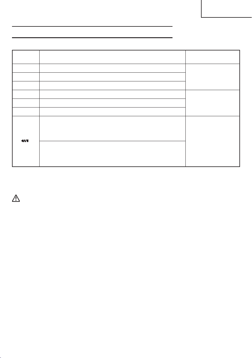
FORMA DE SELECCIONAR EL PAR DE APRIETE
Tabla 7
Español
Posición
de la tapa
1 Aproximadamente 18 in-lbs. (20 kg-cm)
4 Aproximadamente 27 in-lbs. (31 kg-cm)
7 Aproximadamente 37 in-lbs. (43 kg-cm)
10 Aproximadamente 47 in-lbs. (54 kg-cm)
16 Aproximadamente 67 in-lbs. (77 kg-cm)
22 Aproximadamente 87 in-lbs. (100 kg-cm)
Alta velocidad: Aproximadamente 106 in-lbs.
Baja velocidad: Aproximadamente442 in-lbs.
NOTA:
El contenido seleccionado mostrado en la Tabla 7 indica las diferencias de acuerdo con
el tipo de tornillo, el tamaño del tornillo, y el material utilizado.
PRECAUCIÓN:
● Cuando utilice el taladro/destornillador inalámbrico, tenga cuidado de no bloquear el
motor.
Si el motor se bloquea, desconecte inmediatamente la alimentación.
Si deja el motor bloqueado durante cierto tiempo, éste o la batería puede quemarse.
● No apriete con demasiada fuerza ya que las cabezas de los tornillos se dañarían.
Par de apriete
(122 kg-cm)(DS14DMR)
Aproximadamente124 in-lbs.
(143 kg-cm)(DS18DMR)
(510 kg-cm)(DS14DMR)
Aproximadamente550 in-lbs.
(633 kg-cm)(DS18DMR)
Ejemplo de
operación
Apriete de tornillos
para metal.
Apriete de tornillos
para madera blanda.
Apriete de tornillos
para madera dura.
Apriete de tornillos
gruesos cuando se
utilice como
taladro.
83
Page 84

Español
MANTENIMIENTO E INSPECCIÓN
PRECAUCIÓN: Extraiga la batería antes de realizar cualquier trabajo de inspección o
de mantenimiento.
1. Comprobación de las condiciones de la broca
Las brocas deberán comprobarse regularmente. Si una broca está desgastada o rota,
puede patinar o reducir la eficacia del motor, o hacer que se queme.
Reemplace las brocas gastadas por otras nuevas.
PRECAUCIÓN: Si utiliza una broca de destornillador con su punta desgastada o rota,
puede resultar peligroso, porque patinará. Por lo tanto reemplácela
por otra nueva.
2. Comprobación de los tornillos
Los tornillos son peligrosos. Inspecciónelos regularmente y cerciórese de que estén
bien apretados.
PRECAUCIÓN: La utilización de una herramienta eléctrica con tornillos flojos es
extremadamente peligrosa.
3. Mantenimiento de motor
La unidad de bobinado del motor es el verdadero
“corazón” de las harramientas eléctrias.
Prestar el mayor cuidado a asegurarse de que el
bobinado no se dañe y/o se humedezca con aceite
o agua.
4. Inspección de las escobillas de carbón
(Fig. 24)
El motor emplea escobillas de carbón que son
piezas consumibles. Como una escobilla
excesivamente desgastada podría dar problemas
al motor, reemplácelas por otras nuevas cuando
se hayan desgastado o estén cerca del “límite de
desgaste”. Además, mantenga siempre limpias
las escobillas de carbón y compruebe si se
mueven libremente dentro de sus portaescobillas.
Uña de escobilla
de carbón
Límite de uso
0,12" (3 mm)
0,45"
(11,5 mm)
Fig. 24
Saliente de
escobilla de
carbón
NOTA:
Cuando reemplace las escobillas de carbón por
otras nuevas, utilice escobillas Hitachi con número
de código 999054.
84
Fig. 25
Page 85

5. Reemplazar el carbón de contacto
Extraiga la escobilla de carbón quitando primero
la tapa y después enganchando el saliente de la
escobilla de carbón con un destornillador de punta
plana, etc., como se muestra en la Fig. 26.
Cuando instale la escobilla de carbón, elija el
sentido en el que la uña de la misma coincida con
el tubo exterior de la parte de contacto de dicha
escoibilla de carbón. Después empuje la escobilla
de carbón con un dedo, como se muestra en la
Fig. 27. Por último, instale la tapa de la escobilla
de carbón.
PRECAUCIÓN:
● Cerciórese de insertar la uña de la escobilla de
carbón en el tubo exterior de la parte de contacto
de la misma. (Usted podrá insertar cualquiera de
las dos uñas suministradas.)
● Tenda cuidado, porque un error en esta operación
podría deformar la uña de la escobilla y dañar
prematuramente el motor.
Español
Fig. 26
Tubo exterior de la parte
de contacto de la
escobilla de carbón
6. Comprobación del polvo
El polvo podrá eliminarse con un paño suave y seco o ligeramente humedecido en
agua jabonosa.
No utilice lejía, cloro, gasolina, ni diluidor de pintura, porque podrían dañar el plástico.
Fig. 27
7. Eliminación de las baterías agotadas
ADVERTENCIA: No tire las baterías agotadas. Las baterías pueden explotar si se
incineran. El producto que ha adquirido contiene una batería. La
batería es reciclable. Cuando se agote su duración útil, de acuerdo
con las leyes estatales y locales, puede ser ilegal tirar esta batería
a la basura. Solicite a las autoridades locales los detalles sobre
las opciones de reciclado o de la forma de deshacerse
apropiadamente de la batería.
8. Almacenamiento
Guarde la herramienta en un lugar con menos de 40°C (104°F) y fuera del alcance de
niños.
9. Mantenimiento y reparación
Todas las herramientas eléctricas de calidad requieren de vez en cuando el servicio de
mantenimiento o el reemplazo de piezas debido al desgaste producido durante la
utilización normal. Para asegurarse de que solamente se utilicen piezas de reemplazo
autorizadas, todos los servicios de mantenimiento y reparación deberán realizarse
SOLAMENTE EN UN CENTRO DE REPARACIONES AUTORIZADO POR HITACHI.
85
Page 86

Español
ACCESORIOS
ADVERTENCIA: SIEMPRE utilice únicamente repuestos y accesorios autorizados
por HITACHI. NO utilice NUNCA repuestos o accesorios no
previstos para usar con esta herramienta. Si tiene dudas en cuanto
a la seguridad de usar determinado repuesto o accesorio junto
con su herramienta, póngase en contacto con HITACHI.
La utilización de otros accesorios puede resultar peligrosa y
causar lesiones o daños mecánicos.
NOTA:
Las especificaciones están sujetas a cambio sin ninguna obligación por parte de HITACHI.
ACCESORIOS ESTÁNDAR
DS14DMR
(BFK)
DS18DMR
(HLCK)
1
1 Broca de punta Phillips (Núm. 2 × 65L)
(Núm. de código 983006) ........................................... 1
2 Batería (EB14B) ........................................................... 2
3 Cargador de baterías (UC14YFA) .............................. 1
4 Asa lateral (Núm. de código 323001) ........................ 1
5 Caja de plástico ........................................................... 1
1 Broca de punta Phillips (Núm. 2 × 65L)
(Núm. de código 983006) ........................................... 1
2 Batería (EB1830HL) ..................................................... 2
3 Cargador de baterías (UC24YJ) ................................. 1
4 Asa lateral (Núm. de código 323001) ........................ 1
5 Caja de plástico ........................................................... 1
2
Fig. 28
2
Fig. 29
3
31
4
4
5
5
86
Page 87

Español
ACCESORIOS OPCIONALES.....de venta por separado
1. Battería (EB14B) 2. Battería (EB1830HL)
(Para DS14DMR) (Para DS18DMR)
Fig. 30 Fig. 31
NOTA:
Las especificationes están sujetas a cambio sin ninguna obligación por parte de HITACHI.
87
Page 88

Hitachi Koki U.S.A., Ltd.
Please contact HITACHI KOKI U.S.A. LTD.
at 1-800-59-TOOLS (toll free), or HITACHI
AUTHORIZED POWER TOOL SERVICE
CENTER regarding COLLECTION.
Pour le RAMASSAGE, contacter HITACHI
KOKI U.S.A. LTD. au 1-800-59-TOOLS (appel
gratuit), ou UN SERVICE APRES-VENTE
D’OUTILS ELECTRIQUE AGREE PAR
HITACHI.
Con respecto a la RECOLECCIÓN de
baterías, póngase en contacto con HITACHI
KOKI U.S.A. LTD. número 1-800-59-TOOLS
(llamada gratis), o con HITACHI AUTORIZED
POWER TOOL SERVICE CENTER.
Issued by
Hitachi Koki Co., Ltd.
Shinagawa Intercity Tower A, 15-1, Konan 2-chome,
Minato-ku, Tokyo 108-6020, Japan
Distributed by
3950 Steve Reynolds Blvd.
Norcross, GA 30093
Hitachi Koki Canada Co.
6395 Kestrel Road
Mississauga ON L5T 1Z5
88
Code No. C99129061
403
Printed in China
 Loading...