

Page 1
TECHNICAL DATA
AND
SERVICE MANUAL
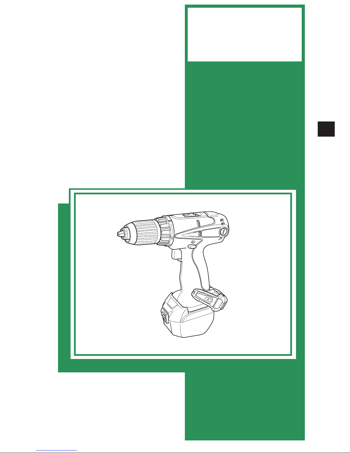
CORDLESS DRIVER DRILL
DS 14DAL
SPECIFICATIONS AND PARTS ARE SUBJECT TO CHANGE FOR IMPROVEMENT
LIST No. G858
Oct. 2006
D
MODEL
DS 14DAL
Hitachi
Power Tools
Page 2

REMARK:
Throughout this TECHNICAL DATA AND SERVICE MANUAL, a symbol(s)
is(are) used in the place of company name(s) and model name(s) of our
competitor(s). The symbol(s) utilized here is(are) as follows:
Symbols Utilized
Competitors
Company Name
Model Name
MAKITA
BDF440
C
Page 3

Page
CONTENTS
1. PRODUCT NAME .......................................................................................................................... 1
2. MARKETING OBJECTIVE ............................................................................................................ 1
3. APPLICATIONS .............................................................................................................................1
4. SELLING POINTS .........................................................................................................................2
4-1. Selling Point Descriptions ............................................................................................................. 3
5. SPECIFICATIONS .........................................................................................................................5
6. COMPARISONS WITH SIMILAR PRODUCTS ............................................................................. 6
6-1. Comparisons of Specifications Listed on Catalogs ....................................................................... 6
7. WORKING PERFORMANCE PER SINGLE CHARGE ................................................................. 7
8. PRECAUTIONS IN SALES PROMOTION ....................................................................................8
8-1. Safety Instructions ........................................................................................................................ 8
8-2. Inherent Drawbacks of Cordless Driver Drills Requiring Particular Attention
During Sales Promotion .............................................................................................................. 10
9. REFERENCE MATERIALS .........................................................................................................12
9-1. Feedback System ....................................................................................................................... 12
10. REPAIR GUIDE ......................................................................................................................... 13
10-1. Precautions in Disassembly and Reassembly .......................................................................... 13
10-2. Precautions in Disassembly and Reassembly of Battery Charger ........................................... 21
11. STANDARD REPAIR TIME (UNIT) SCHEDULES ..................................................................... 22
Assembly Diagram for DS 14DAL
Page 4

--- 1 ---
1. PRODUCT NAME
Hitachi 14.4 V Cordless Driver Drill, Model DS 14DAL
2. MARKETING OBJECTIVE
The new Model DS 14DAL is a compact and lightweight cordless driver drill. It is the upgraded version of the well-
reputed Model DS 12DM. Features of the Model DS 14DAL include the following:
(1) Greater maximum torque
(2) Equipped with the Type EBM 1430R lithium-ion battery
We aim to expand sales with the Model DS 14DAL.
NOTE: The Type EBM 1430R 14.4 V lithium-ion battery that comes with the Model DS 14DAL is not
interchangeable with the Type EBL 1430 lithium-ion battery that has already been on the market.
3. APPLICATIONS
Tightening and loosening wood screws, tapping screws, machine screws and nuts
Drilling into wood, metal and plastic materials
Page 5
--- 2 ---
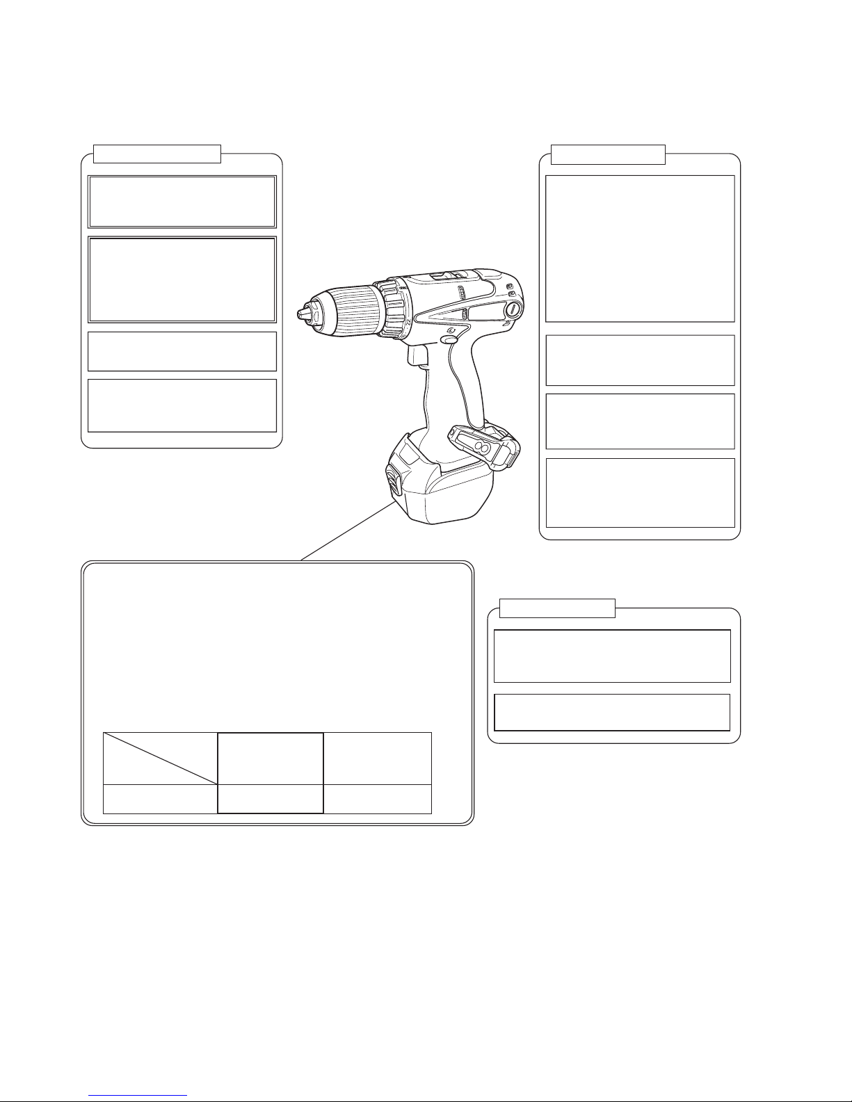
Higher performance
Greater maximum torque
• Maximum torque 38 N•m
(386 kgf•cm)
Improved overload durability
(improved cooling efficiency)
• Large radial fan
• Optimally designed cooling
air path
22-stage clutch
• Fine torque adjustment
Manual tightening mechanism
• Usable as a manual
screwdriver
Long-life lithium-ion battery
The lithium-ion battery is of a safe design thanks to the built-in
overdischarge protection circuit, overload protection circuit, and
voltage monitoring circuit for each cell.
• The battery is equipped with the overdischarge protection
circuit to prevent overdischarge (overuse) of the battery.
• The battery is equipped with the voltage monitoring circuit for
each cell to prevent overcharge (excessive charging) of the
battery.
Easier to operate
Hook with a yellow LED light
• LED light is convenient for
operation in a dark place.
• Convenient for carrying and
storing the tool.
• Angle-adjustable in 5 steps
with one-touch simple
operation
• Mountable on either side
Injection-molded case
• Big storage space
• Durable hinges
Slip-resistant clutch dial
• Soft and easy to turn thanks
to the elastomer resin
Comfortably shaped handle
• Soft and slip-resistant thanks
to the elastomer resin
• Slim handle
Easier to maintain
Externally replaceable carbon brushes
• The carbon brushes are singly
replaceable.
Separate-type motor
• The armature is singly replaceable.
4. SELLING POINTS
Number of charging/
discharging
Model DS 14DAL
+
Type EBM 1430R
(Lithium-ion battery)
C
(Lithium-ion battery)
Approx. 1,500 500
Page 6
--- 3 ---
1.6
4-1. Selling Point Descriptions
4-1-1. Greater maximum torque
The Model DS 14DAL is a high-power driver drill with its maximum torque 38 N•m {386 kgf•cm} thanks to the
adoption of the powerful rare-earth magnet motor that is well-reputed in the Model DS 12DM. It enables drilling
large-diameter holes and tightening large-diameter screws. (See "7. WORKING PERFORMANCE PER SINGLE
CHARGE" for comparison of working speed as a guide.)
DS 14DAL
EBM1430R (3.0)
203
237
76
1.6
38 {386 kgf•cm}
DS 12DM
C
EB1230HL (3.0)
Battery (Capacity [Ah])
Entire length [mm]
Entire height [mm]
Entire width [mm]
Weight [kg]
Maximum torque [N•m]
229
203
36 {367 kgf•cm}
220
73
1.7
EB1220BL (2.0)
186
242
79
1.6
38 (386 kgf•cm)
4-1-2. Long-life 14.4 V lithium-ion battery Type EBM 1430R
The Type EBM 1430R lithium-ion battery is equipped with the overdischarge protection circuit, overload protection
circuit, and voltage monitoring circuit for each cell to prevent reduction of the battery life due to overdischarge
(overuse) or overcharge (excessive charging). The Type EBM 1430R lithium-ion battery can be charged/
discharged about 1,500 times, while C can be charged/discharged about 500.
Precautions for use of the Type EBM 1430R lithium-ion battery
The Type EBM 1430R lithium-ion battery is equipped with a protective function that automatically stops output to
extend the battery life. The motor may stop automatically in either of the following case or even if the
switch is depressed continuously during operation. This is because the protective function is activated.
The battery is not faulty.
The motor may stop automatically when the remaining battery level is low (when the battery voltage is
decreased to about 8 V). Charge the battery immediately in such case.
The motor may stop if the Model DS 14DAL is overloaded. In such case, release the switch and eliminate the
cause of the overload problem. Then the Model DS 14DAL is operable.
Please instruct the customers on the above precautions.
NOTE The Type EBM 1430R lithium-ion battery that comes with the Model DS 14DAL is not
interchangeable with the Type EBL 1430 lithium-ion battery that has already been on the market.
4-1-3. Hook with a yellow LED light
This hook is convenient for carrying the Model DS 14DAL by hanging on a belt and also for storing. In addition,
the yellow LED light can be conveniently used as a subsidiary light for operation in a dark place. Features of the
hook include the following:
The hook is designed to be drawn out quickly when needed and retracted quickly when not needed with one-
touch simple operation to prevent from interfering with other work. The hook angle is adjustable in 5 steps.
The hook is mountable on either side. The hook can be easily mounted by using a flat-blade screwdriver or a
coin.
1
2
1
2
1
2
Page 7
--- 4 ---
The yellow LED light is usable by turning on the independent light switch when needed. It is designed to light
an object diagonally to avoid creating a shadow of the drill bit or the operator's hand supporting a screw.
Thanks to the internal circuit, the LED light is automatically turned off about 15 minutes later.
4-1-4. Injection-molded case
The injection-molded case has enough storage space to accommodate many accessories. In addition, the case is
more durable than the conventional one thanks to the new hinge brackets.
4-1-5. Improved overload durability (improved cooling efficiency)
The Model DS 14DAL is equipped with the same separate-type motor as a driver drill with a power cord. To
improve the overload durability in continuous operation, the large radial fan increases the volume of air and the
optimally designed cooling air path that is descended from the Model DS 12DM increases the cooling efficiency.
4-1-6. Slip-resistant 22-stage clutch dial
The 22-stage clutch dial ensures fine torque adjustment. The clutch dial is made of elastomer resin (soft resin). It
is soft, slip-resistant and easy to operate for torque setting.
4-1-7. Manual tightening mechanism
When a screw cannot be driven completely with the torque set by the clutch dial, turn off the switch and use the
Model DS 14DAL as a screwdriver by turning the main body manually (maximum manual tightening torque: 22.5
N•m {230 kgf•cm}).
4-1-8. Comfortably shaped handle
The handle is soft, slip-resistant, and comfortably fits in a hand thanks to the elastomer resin. In addition, the
switch section of the handle is thinned for comfortable gripping.
4-1-9. Externally replaceable carbon brushes and separate-type motor
The carbon brushes are replaceable from the outside. The armature is also singly replaceable because the Model
DS 14DAL is equipped with the same separate-type motor as a driver drill with a power cord. Thus the Model
DS 14DAL is easier to maintain.
4-1-10. Others
The switch terminal is isolated to prevent scratching the contact area due to vibration of the battery.
The battery contact (holding) area of the housing is increased to prevent rattling of the battery due to wear.
3
Diagonal lighting to avoid
creating a shadow
3
Mountable on either side
2
Angle-adjustable in 5 steps
1
Page 8

Page 9

--- 6 ---
Slip torque
[22 positions]
0.49 to 4.4 N•m
{5 to 45 kgf•cm}
[22 positions]
0.49 to 4.4 N•m
{5 to 45 kgf•cm)
Not listed
Wood screw
6.8 mm dia. x 50 mm6.8 mm dia. x 50 mm
6. COMPARISONS WITH SIMILAR PRODUCTS
6-1. Comparisons of Specifications Listed on Catalogs
Maker
Model
Capacity
Screw
driving
Drilling
No-load
rotation
speed
Low
High
HITACHI
DS 14DAL
0 to 350/min
0 to 1,200/min
0 to 350/min
0 to 1,200/min
DS 12DM
C
0 to 400/min
0 to 1,400/min
Feedback
Switch
Provided
Provided
203 mm
Provided
Provided
Not listed
Provided Brake
Weight
1.6 kg
Overall length
Overall height
237 mm
Mild steel
Aluminum
Wood
13 mm
13 mm
27 mm
13 mm
13 mm
27 mm
13 mm
13 mm
27 mm
Tightening type
Tightening type
Tightening type
Preventive mechanism
against loosening
Drill chuck
Keyless
Type
Plastic Plastic
Sleeve material
Battery
Nominal voltage (V)
12 14.4
Reversing switch Push-button type Push-button type
Push-button type
Clutch dial
Spotlight
Elastomer and polyamide resins
Provided
Elastomer and polyamide resins
Provided
Unknown
Provided
Hook
Strap
Provided (One-touch type)
Provided
Provided (One-touch type)
Provided
Provided (Fixed with fittings)
Provided
Nominal capacity (Ah)
3.0
Type EBM 1430R
45
Overall width 76 mm
2MRK (2HLFK) (2BLFK)
Machine screw
6 mm 6 mm
Max. torque
38.0 N•m {386 kgf•cm} 36.0 N•m {367 kgf•cm}
Not listed
Low
High
10.0 N•m {102 kgf•cm}
38.0 N•m {386 kgf•cm}
[16 positions]
Motor
Carbon brushes
DC magnet
External
Internal
2-speed gear
Provided
Manual tightening mechanism
Provided Provided
Provided
External
DC magnet
DC magnet
Provided
Provided
9.0 N•m {92 kgf•cm}
Capacity
13 mm
Keyless
Nominal charging time (min.)
14.4
3.0
203 mm
1.7 kg
229 mm
73 mm
186 mm
1.6 kg
242 mm
79 mm
2270 50
3.0 2.0
EB 1230HL EB 1220BL
Auxiliary symbol
13 mm
Keyless
Plastic
13 mm
6.8 mm dia. x 50 mm
6 mm
Page 10

--- 7 ---
7. WORKING PERFORMANCE PER SINGLE CHARGE
Drilling and fastening performance comparison per charge
*: Number of Teks screws or machine screws fastened per charge
The above table shows the test data when using batteries of nominal capacity 3.0 Ah.
NOTE) The above table shows an example of test data. As actually measurements may vary depending on
ambient temperature, sharpness of drill bit, types of workpieces, working method, etc., this data should be
used as a comparative guide only.
Type of work
Maker
Model name
No. of drilling or fastening operations per charge
Drilling
speed
(sec./pc.)
*0
0
*600
150
*1000
300
*1400
450
<High speed>
DS 14DAL
HITACHI
C
DS 12DM
1.1
1.2
1.0
DS 14DAL
HITACHI
C
DS 12DM
4.8
5.7
4.5
DS 14DAL
HITACHI
C
DS 12DM
18.5
25.0
17.3
DS 14DAL
HITACHI
C
DS 12DM
4.2
5.7
3.8
DS 14DAL
HITACHI
C
DS 12DM
1.0
1.3
0.9
DS 14DAL
HITACHI
C
DS 12DM
0.5
0.6
0.5
290
350
375
140
200
215
13
18
20
110
150
165
495
670
740
880
1150
1140
<High speed>
<High speed>
<20 kg thrust, high speed>
<15 kg thrust, low speed>
<Low speed>
Page 11

--- 8 ---
8. PRECAUTIONS IN SALES PROMOTION
8-1. Safety Instructions
In the interest of promoting the safest and most efficient use of the Model DS 14DAL cordless driver drill by all of
our customers, it is very important that at the time of sale, the salesperson carefully ensures that the buyer
seriously recognizes the importance of the contents of the Handling Instructions, and fully understands the
meaning of the precautions listed on the Caution Plate and Name Plate attached to each tool.
A. Handling instructions
Salespersons must be thoroughly familiar with the contents of the Handling Instructions in order to give pertinent
advice to the customer. In particular, they must have a thorough understanding of the precautions for use of the
cordless tools which are different from those of ordinary electric power tools.
(1) Before use, ensure that the unit is fully charged.
New units are not fully charged. Even if the units were fully charged at the factory, long periods of inactivity,
such as during shipping, cause the storage battery to lose its charge. Customers must be instructed to fully
charge the unit prior to use.
(2) Connect the charger to an AC power outlet only.
Use of any other power source (DC outlet, fuel powered generator, etc.) will cause the charger to overheat and
burn out.
(3) Do not use any voltage increasing equipment (transformer etc.) between the power source and the charger.
If the charger is used with voltage higher than that indicated on the unit, it will not function properly.
(4) Conduct battery charging at an ambient temperature range of 0ûC --- 40ûC.
Special temperature sensitive devices are employed in the charger to permit rapid charging. Ensure that
customers are instructed to use the charger at the indicated ambient temperature range. At temperature
under 0ûC the thermostat will not function properly, and the storage battery may be overcharged. At
temperature over 40ûC, the storage battery cannot be sufficiently charged. The optimum temperature range is
20ûC --- 25ûC.
(5) The battery charger should not be used continuously.
At high ambient temperature, if over three storage batteries are charged in succession, the temperature of the
coils on the transformer will rise and there is a chance that the temperature fuse inserted in the interior of the
transformer will inadvertently melt. After charging one battery, please wait about 15 minutes before charging
the next battery.
(6) Do not insert foreign objects into the air vents on the charger.
The charger case is equipped with air vents to protect the internal electronic components from overheating.
Caution the customer not to allow foreign materials, such as metallic or flammable objects, to be dropped or
inserted into the air vents. This could cause electrical shock, fire, or other serious hazards.
Page 12

--- 9 ---
(7) Do not attempt to disassemble the storage battery or the charger.
Special devices, such as a thermostat, are built into the storage battery and the charger to permit rapid
charging. Incorrect parts replacement and/or wiring will cause malfunctions which could result in fire or other
hazards. Instruct the customer to bring these units to an authorized service center in the event repair or
replacement is necessary.
(8) Disposal of the Type EBM 1430R storage battery
Ensure that all customers understand that Type EBM 1430R storage battery should be returned to the Hitachi
power tool sales outlet or the authorized service center when it is no longer capable of being recharged or
repaired. If thrown into a fire, the battery may explode.
B. Caution plates
(1) The following cautions are listed on the Name Plate attached to Type EBM 1430R storage battery.
Read thoroughly HANDLING INSTRUCTIONS
before use. Do not disassemble nor throw into fire.
CAUTION
For Europe
Page 13

--- 10 ---
8-2. Inherent Drawbacks of Cordless Driver Drills Requiring Particular Attention During Sales Promotion
The cordless driver drill offers many advantages; it can be used in places where no power source is available, the
absence of a cord allows easy use, etc. However, any cordless tool has certain inherent drawbacks.
Salespersons must be thoroughly familiar with these drawbacks in order to properly advise the customer in the
most efficient use of the tool.
A. Suggestions and precautions for the efficient use of the tool
(1) Use the cordless driver drill for comparatively light work.
Because they are battery driven, the output of the motor in cordless driver drills is rather low in comparison
with conventional electric power tools. Accordingly, they are not suitable for continuous drilling of many holes
in succession, or for drilling into particularly hard materials which creates a heavy load. Salespersons should
recommend conventional electric power tools for such heavy work.
(2) Drilling of large diameter holes should be conducted at low speed.
Instruct the customer that drilling of large diameter holes or other work which requires particularly strong
torque should be done at low speed. Because there is less torque at high speed, attempting such work at high
speed will not improve working efficiency.
(3) Do not insert a foreign object into body vent holes.
The body of this tool has vent holes for improving the cooling efficiency. As a fan is built into the motor, a
foreign object inserted through a vent hole may cause a failure. Please instruct customers to never insert a
foreign object into the vent hole.
(4) Avoid "Locking" of the motor.
Locking of the motor will cause an overload current that could result in burning of the motor and/or rapid
deterioration of the battery. Salespersons should advise the customer to immediately release the switch and
stop operation if the motor becomes locked. (A jammed drill bit can be disengaged from the workpiece
material by setting the switch to reverse rotation, or by manually turning the main body of the tool.)
(5) Variation in amount of work possible per charge
Although the nominal chargeable capacity of the storage batteries used with the Model DS 14DAL is 3.0 Ah,
the actual capacity may vary within 10% of that value depending on the ambient temperature during use and
charging, and the number of times the batteries have been recharged. It should be noted that other factors
which may have a bearing on the amount of work possible per charge are the working conditions (ambient
temperature, type and moisture content of the workpiece, sharpness of the drill bit, etc.) and the operational
skill of the user.
(6) Precautions in the use of HSS drill bits
Although the Model DS 14DAL is designed for drilling capacities of 27 mm in wood, and 13 mm in aluminum
and mild steel, this capability is not as efficient as conventional electric power tools.
In particular, when drilling through aluminum material with a 13 mm drill bit, the drill tends to become locked
when the drill bit penetrates through the material. For this reason, the customer should be cautioned to
reduce the thrust on the main body of the drill when drilling completely through the material to avoid locking
the tool. Repeated locking of the drill causes excessive current flow from the batteries which not only
decreases the amount of work possible per charge, but could also result in burning of the motor.
Page 14

--- 11 ---
(7) Securely tighten the sleeve of the keyless chuck.
The keyless chuck may slip during operation if the shape of the drill bit shank is cylindrical depending on the
surface conditions, materials, etc. Please instruct the customers to retighten the keyless chuck more securely
if the keyless chuck slips during operation. The holding force of the keyless chuck is increased as the
tightening force of the keyless chuck is increased. The Model DS 14DAL is equipped with the locking device
to prevent loosening of the keyless chuck. The sleeve makes noise when tightening or loosening. This is
because of the locking device and there is no problem.
(8) Avoid continuous use.
Although the Model DS 14DAL can bear continuous operation under certain conditions, operating conditions
are different depending on material of workpiece and sharpness of the drill bit in use. Please instruct the
customers to avoid continuous use of the Model DS 14DAL and take a pause about 15 minutes after a single
charge operation as a guide.
B. Suggestions and precautions for the efficient use of the charger and storage batteries
If the storage battery Type EBM 1430R is exposed to direct sunlight for an extended period or if the
temperature of the battery is high immediately after it has been used in the tool, the pilot lamp (red) may not
be turned on when the battery is connected to the charger. Chargeable temperature ranges of each type of
battery are specified as follows.
Type EBM 1430R: from 0ûC to 50ûC
In such a case, the customer should be advised to place the battery in a shaded area with a good airflow, and
allow sufficient cooling before recharging. This phenomenon is common to all existing batteries that employ a
thermostat. The cooling time required before charging varies from a few minutes to about 30 minutes,
depending on the load, duration of use, and ambient temperature.
Page 15

--- 12 ---
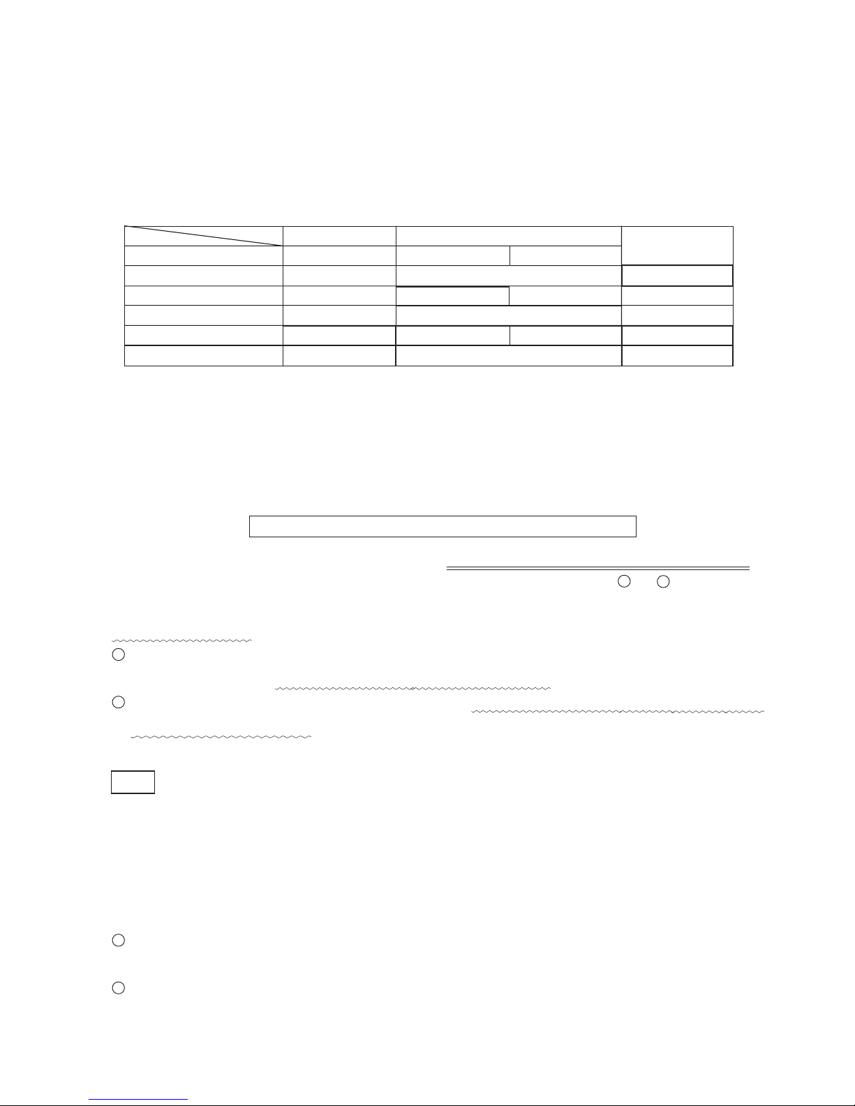
Schematic diagram of the feedback system
9. REFERENCE MATERIALS
9-1. Feedback System
The Model DS 14DAL has the variable speed switch equipped
with the feedback system. This feedback system ensures a
sufficiently large torque even in the variable speed range.
For example, when operating the Model DS 14DAL at a
speed about 80% of the full speed, the maximum torque is
about 95% of that at a full speed (curve "A"). Even when the
Model DS 14DAL is operated at a speed about 30% of the full
speed, the maximum torque does not decrease under about
65% of that at a full speed (curve "B") to ensure a sufficiently
large torque at a low speed.
Besides, the braking function allows the driver unit to stop
rotation immediately when the trigger switch is released,
To rq ue (%)
Rotation speed (%)
which is a convenient feature for continuous screw tightening or drilling works. The step-less variable speed
mechanism controls the speed depending on the depressed amount of the trigger switch within the range from 0
to 350 cycles per minute for the low speed mode and from 0 to 1,200 cycles per minute for the high speed mode.
Thanks to this mechanism, positioning is easily done for screw tightening and drilling works.
Page 16

--- 13 ---
10. REPAIR GUIDE
Be sure to remove the storage batteries from the main body before servicing. Inadvertent triggering of the switch
with the storage battery connected will result in danger of accidental turning of the motor.
10-1. Precautions in Disassembly and Reassembly
The [Bold] numbers in the descriptions below correspond to the item numbers in the Parts List and exploded
assembly diagram for the Model DS 14DAL.
10-1-1. Disassembly
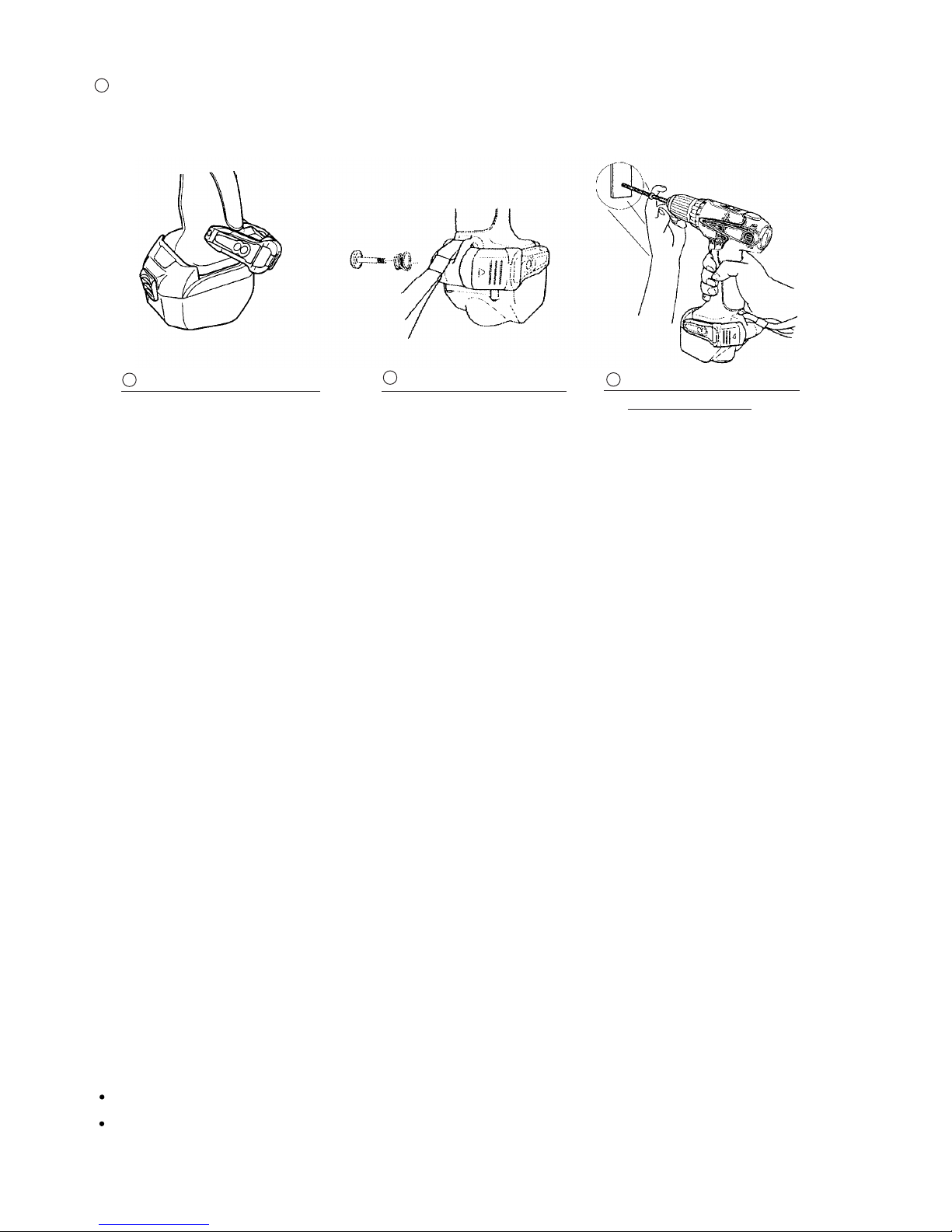
(1) Removal of the Hook Ass'y (W/Light) [44]
Remove the Special Screw M5 [49] with a flat-blade screwdriver or a coin. Remove the Hook Ass'y (W/Light)
[44] and the Hook Spring [48].
(2) Removal of the Carbon Brushes [33]
Remove the Brush Cap [34] first then pry the Carbon Brush [33] off with a flat-blade screwdriver (at the
position of collars). Remove the Brush Caps [34] and the Carbon Brushes [33] at both sides.
(3) Removal of the Drill Chuck [2]
Perform the following steps (a) and (b) with the main unit mounted in the vise for removal of the Drill Chuck
[2]. At this time, it is recommended to sandwich a cloth between the main unit and the vise to prevent the
Housing Set [37] from being scratched.
(a) Fully open the jaws of the Drill Chuck [2] and remove the Special Screw (Left Hand) M6 x 23 [1] by turning
clockwise (be careful that it is a left-handed screw).
(b) Hold the hexagonal portion at the tip of the Drill Chuck [2] with a 19-mm socket wrench as shown in
Fig. 1 then turn it counterclockwise to remove the Drill Chuck [2].
(4) Adjust the Clutch Dial [4] to "1."
(5) Disassembly of the main unit
Remove the eight Tapping Screws (W/Flange) D3 x 16 (Black) [35] from the main unit. Holding the battery
chamber of Housing (B) [37], gently remove Housing (B) [37].
Then the inside parts can be removed in an assembled or single state. All the parts can be easily removed by
raising the Clutch Dial [4]. Parts are separated into the drive unit (an assembly of the armature and the gear
unit), power supply unit, Pushing Button [41] and Strap (Black) [47].
Socket wrench
Fig. 1
Vise
19-mm socket
Cloth
Hexagonal portion
Page 17

--- 14 ---
(6) Disassembly of the drive unit
(a) Remove the Clutch Dial [4] and the Click Spring [9] from the Front Case [8].
(Note) Do not remove the Nut [5] from the Front Case [8] in this step.
(b) Remove the Shift Arm [20] from the Gear Box Ass'y [3] and remove the Shift Knob [38] from the Shift Arm
[20]. Do not deform the Shift Arm [20] by applying excessive force.
(c) Turn the Motor Spacer [28] until a click is heard counterclockwise viewing from the rear of the Armature
[29]. Remove the Motor Spacer [28] from the Rear Case [18]. Thus the armature unit is separated from
the gear unit.
(7) Disassembly of the armature unit
(a) Removal of the Magnet [30]
Note that the magnetic force of the Magnet [30] is strong. Hold the Motor Spacer [28] securely and pull
toward the back of the Armature [29] to remove (see Fig. 8).
(Note) Be careful that the ball bearing and the washer behind the Armature [29] may be attracted to the
Magnet [30] and come off the Armature [29] when removing the Magnet [30]. Do not remove washer
(M) that is attracted to the Magnet [30] by the magnetic force.
(b) Removal of the Dust Guard [31]
Remove the Dust Guard [31] that is attracted to the Magnet [30] by the magnetic force (see Fig. 8).
(c) Removal of the Motor Spacer [28]
Remove the Motor Spacer [28] from the Armature [29]. If it is too hard to remove, support the Motor
Spacer [28] and press down the tip of the armature shaft of the Armature [29] with a hand press.
(8) Disassembly of the gear unit
(a) Disassembly of the deceleration mechanism
Turn Plate (A) [27] mounted in the Rear Case [18] counterclockwise to remove. Take out the First Ring
Gear [26], Planet Gear (A) Set (4 pcs.) [25], Pinion (B) [24], Planet Gear (B) Set (4 pcs.) [23], Pinion (C)
[22] and Slide Ring Gear [21] in order. Then remove the Screw Set D3 x 12 (4 pcs.) [19] that connects the
Front Case [8] with the Rear Case [18]. Take out Plate (B) [17], Planet Gear (C) Set (3 pcs.) [16], Carrier
[15], Ring Gear [13], Needle Roller (C) Set (6 pcs.) [14], Lock Ring [12], six Steel Balls D5 [11] and six
Rollers [10] from the Front Case [8] in order.
(Note) Do not lose small parts. Pay special attention to the six Steel Balls D5 [11], six Rollers [10] and
Needle Roller (C) Set (6 pcs.) [14] because they are apt to roll.
(b) Disassembly of the clutch mechanism
Turn the Nut [5] counterclockwise to remove from the Front Case [8] . Take out the Spring [6] and the
Thrust Plate [7] in order.
(Note) Do not disassemble the Front Case [8].
(9) Disassembly of the power supply unit
Remove two Machine Screws (W/Sp. Washer) M3 x 4 [39] and a Machine Screw (W/Sp. Washer) M3 x 4 [39].
Then the DC-Speed Control Switch [40] and the Fin [43] can be removed.
(Note) Be careful in handling the FET and the internal wires of the DC-Speed Control Switch [40] as they are
apt to be broken at their roots. Do not disconnect three FET internal wires and two terminal internal
wires soldered to the DC-Speed Control Switch [40].
Page 18

--- 15 ---
10-1-2. Reassembly
Reassembly can generally be carried out as the reverse of the disassembly procedure, with some items to be
noted as follows.
(1) Reassembly of the power supply unit
Perform wiring according to the wiring diagram (Fig. 2). Pay attention to the connecting direction of the
internal wires and the terminals.
(Note) Be careful in handling the FET and the internal wires of the DC-Speed Control Switch [40] as they are
apt to be broken at their roots.
Fig. 2
(2 pcs.)
[32]
Internal wire (red)
[6]
Internal wire (black)
Protrusion
Notch
[39]
[40]
[43]
[39]
Internal wire
FET
Fig. 3
[7]
[8]
(2) Reassembly of the clutch mechanism
Mount the Thrust Plate [7] and the Spring [6] to the Front Case [8] in order (see Fig. 3). At this time, align the
notch of the Thrust Plate [7] with the protrusion of the Front Case [8].
Page 19

--- 16 ---
(b) Screw the Nut [5] in the Front Case [8] (see Fig. 4).
Align the mark (i) on the Nut [5] with the mark on the Front Case [8] then screw it in. Rotate the Nut [5]
about a turn clockwise to align the mark (ii) on the Nut [5] with the mark on the Front Case [8]. At this time,
check that the "Y" surface of the Nut [5] is almost flush with the "Z" surface of the Front Case [8].
Fig. 4
Screw-in start position
Mark (i)
Mark
(3) Reassembly of the manual tightening mechanism
(a) Mount the Lock Ring [12] to the Front Case [8] so that the
protrusion of the Lock Ring [12] aligns with the concave portion
of the Front Case [8] (see Fig. 5). At this time, mount the Lock
Ring [12] so that the stepped protrusion faces forward.
(b) Mount Needle Roller (C) Set (6 pcs.) [14] (see Fig. 5).
(Note) Do not apply grease to the Lock Ring [12] and Needle
Roller (C) Set [14]. Application of grease renders the
manual tightening mechanism inoperative.
[8]
[5]
Fig. 5
[14]
[12]
[8]
[5]
"Y" surface
"Y" surface
"Z" surface
[8]
Concave
portion
Protrusion
Stepped portion
Screw-in end position
Mark (ii)
Mark
(6 pcs.)
(4) Reassembly of the deceleration mechanism
(a) Apply grease (Hitachi Motor grease No. 29) to the engaging portions of each gear, needle roller unit, and
contacting surfaces of the steel balls of the ring gear properly.
(b) Mount the parts from the Roller [10] to Plate (A) [27] to the parts assembled in the above (3) in order (see
Fig. 6).
Mount the Roller [10] first then mount the Steel Balls D5 [11].
Pay attention to the mounting direction of the Ring Gear [13], Carrier [15], Slide Ring Gear [21], Pinion (C)
[22] and Pinion (B) [24] (see Fig. 6).
Mount the Front Case [8] to the Rear Case [18] so that the concave portion of the Front Case [8] aligns
with the protrusion of the Rear Case [18] (see Fig. 11).
1
2
3
"Z" surface
Page 20

--- 17 ---
[13]
[15]
[16]
[17]
[8]
[11]
[10]
[24]
[25]
[26]
[27]
[21] [23]
[22]
[18]
[19]
(6 pcs.)
Fig. 6
(6 pcs.)
(3 pcs.) (4 pcs.)
(4 pcs.)
(4 pcs.)
Groove portion
Fig. 7
[27]
[18]
Concave
portion
Concave
portion
Protrusion
Protrusion
Fig. 8
[28]
[29]
[31]
[30]
Notch
Washer (M)
Washer
Ball
bearing
Fan
Fit the protrusion of Plate (A) [27] in the concave portion of the Rear Case [18] and turn it clockwise
viewing from the armature until it contacts the Rear Case [18] (see Fig. 7).
4
(5) Reassembly of the armature unit
(a) Mounting the Motor Spacer [28]
Mount the Motor Spacer [28] to the Armature [29]. If it is too hard to mount, support the Motor Spacer [28]
and press down the rear end of the armature shaft of the Armature [29] with a hand press.
(b) Mounting the Magnet [30]
Mount the Magnet [30] to the Armature [29] so that the notch of the Magnet [30] faces the rear of the
Armature [29]. Hold each part securely as the Armature [29] may be attracted to the Magnet [30] by the
strong magnetic force.
(Note) Be careful that the ball bearing and the washer at the rear of the Armature [29] may come off due to the
magnetic force of the Magnet [30].
Page 21

--- 18 ---
(c) Mounting the Dust Guard [31]
Mount the Dust Guard [31] to the Magnet [30] so that the protrusion of the Dust Guard [31] aligns with
the notch of the Magnet [30]. Hold each part securely as the Dust Guard [31] may be attracted to the
Magnet [30] by the strong magnetic force (see Fig. 9).
(b) Mounting the Shift Arm [20] and the Shift
Knob [38] (See Fig. 11.)
Mount the Shift Arm [20] to the protruded
side of the Rear Case [18] facing its bent
portion forward. At this time, insert the
protrusion of the Shift Arm [20] into the hole
of the Rear Case [18] and check that the
protrusion is inserted into the groove of the
Slide Ring Gear [21] that is mounted in the
Rear Case [18] (see Fig. 6).
Insert the Shift Arm [20] into the groove of
the Shift Knob [38] facing "LOW" indication
on the Shift Knob [38] backward.
Notch
Protrusion
Fig. 10
Fig. 9
[31]
[30]
(6) Reassembly of the drive unit
(a) Fit the protrusion of the Motor Spacer [28] in the concave portion of the Rear Case [18] engaging the
pinion of the Armature [29] with Planet Gear (A) Set (4 pcs.) [25]. Turn it fully clockwise viewing from the
rear of the Armature [29] (see Fig. 10).
Protrusion
Protrusion
Pinion
Fig. 11
[20]
[38]
[28]
Concave
portion
Concave
portion
[18]
[25]
(c) Mounting the Click Spring [9] and the Clutch Dial [4] (See Fig. 12.)
Mount the Click Spring [9] to the Front Case [8].
1
2
Protrusion
Top view
Side view
Indication "LOW"
Groove portion of slide ring gear
Concave
portion
1
Page 22

--- 19 ---
Fig. 12
Fig. 13
Protrusion
[32]
Protrusion
[8]
[9]
[5]
[4]
[5]
[4]
[30]
[28]
[8]
[4]
[37]
Notch
Groove
Protrusion
Protrusion
Protrusion
Concave
portion
Concave
portion
Concave
portion
Protrusion
Mount the Clutch Dial [4].
The Nut [5] has three protrusions. One of these protrusions is wider than the others. The Clutch Dial [4]
has three concave portions. One of these concave portions is wider than the others. Mount the Nut [5] to
the Clutch Dial [4] aligning the wider protrusion of the Nut [5] with the wider concave portion of the Clutch
Dial [4] (the wider concave portion of the Clutch Dial [4] is at the position where indicated with "1" viewing
from the outside). Check that the protrusion of the Click Spring [9] is inserted into the groove inside the
Clutch Dial [4].
2
Wider protrusion
Protrusion
Protrusion
Concave
portion
Concave portion
Indicated with "1"
Groove
Wider concave
portion
A
B
(7) Reassembly of the main unit
(a) Mount the power supply unit and the drive unit that were reassembled in the above procedure to Housing
(A) [37]. At this time, align the protrusions of the Brush Block [32], Front Case [8] and Motor Spacer [28]
with the concave portions of Housing (A) [37], the notch of the Magnet [30] with the protrusion of Housing
(A) [37], and the groove of the Clutch Dial [4] with the protrusion of Housing (A) [37] (see Fig. 13).
Page 23

--- 20 ---
(b) Apply silicone grease (Shin-Etsu Chemical KS609) to the surface of the Fin [43] where the Magnet [30]
contacts. Then mount the Fin [43] to Housing (A) [37].
(Note) Be careful in handling the FET and the internal wires of the DC-Speed Control Switch [40] as they
are apt to be broken at their roots.
(c) Mount the DC-Speed Control Switch [40] that was not mounted in the above step (a) to Housing (A) [37].
Mount the Pushing Button [41] to Housing (A) [37]. Check that the protrusion of the forward/reverse
changeover lever of the DC-Speed Control Switch [40] is inserted into the U-shaped groove of the Pushing
Button [41].
(d) Mount the Strap (Black) [47] to Housing (A) [37].
(e) Align Housing (A) [37] with Housing (B) [37] and secure it with the eight Tapping Screws (W/Flange)
D3 x 16 (Black) [35].
(f) Verify proper operation of the Clutch Dial [4] and the Shift Knob [38]. When the reassembly procedure up
to step (e) is completed, ensure that every indication on the Clutch Dial [4] from the number "1" to the drill
mark " " is aligned with the triangle mark on the Housing Set [37] respectively and the Clutch Dial [4]
turns moderately. If any indication on the Clutch Dial [4] cannot reach the triangle mark on the Housing Set
[37], correctly remount the Clutch Dial [4] referring to step (2) or (6) (c) as it is improperly mounted. Verify
proper operation of the Shift Knob [38]. Check that the speed changes between high and low properly by
shifting the Shift Knob [38]. If the speed cannot change properly or moderately, correctly remount the Shift
Knob [38] referring to step (4) (b) or (6) (b) as it is improperly mounted.
Mount the Dust Guard [31] to the Brush Block [32] aligning the protrusion of the Dust Guard [31] with the
concave portion of the Brush Block [32] (Fig. 14).
At this time, do not mount the DC-Speed Control Switch [40].
Fig. 14
[32]
Protrusion
[31]
Concave
portion
(8) Mounting the Drill Chuck [2]
Mount the Drill Chuck [2] to the spindle and tighten the Special Screw (Left Hand) M6 x 23 [1].
(9) Mounting the Carbon Brushes [33]
Mount the two Carbon Brushes [33] to the Brush Block [32] and secure the two Brush Caps [34] to the Brush
Block [32]. Check that the claws of the Carbon Brushes [33] are properly inserted into the brush tubes.
Page 24

--- 21 ---
(10) Reassembly of the Hook Ass'y (W/Light) [44]
Check that the V-Lock Nut M5 [46] is mounted to the Hook Ass'y (W/Light) [44]. Mount the Hook Spring [48]
and secure it with the Special Screw M5 [49]. Make sure to mount the Hook Spring [48] with its larger
diameter side pointing inward the housing.
(11) Other precautions in reassembling
After completion of reassembly, check that the rotating direction of the Drill Chuck [2] matches the position of
the Pushing Button [41]. When the Pushing Button [41] is pressed from the (R) side, the rotating direction of
the Drill Chuck [2] should be clockwise as viewed from behind. Check that the runout of the Drill Chuck [2] is
0.8 mm or less at the position 110 mm away from the tip of the chuck using a 12-mm dia. test bar.
(12) Screw tightening torque
Special Screw (Left Hand) M6 x 23 [1] : 3.92 --- 4.9 N•m (40 --- 50 kgf•cm)
Drill Chuck [2] : 17.6 --- 21.6 N•m (180 --- 220 kgf•cm)
Screw Set D3 x 12 [19] : 0.62 --- 0.94 N•m (6 --- 10 kgf•cm)
Brush Cap [34] : 0.68 --- 0.88 N•m (7 --- 9 kgf•cm)
Tapping Screw (W/Flange) D3 x 16 (Black) [35] : 1.0 --- 1.6 N•m (10 --- 16 kgf•cm)
Machine Screw (W/Sp. Washer) M3 x 4 [39] : 0.29 --- 0.39 N•m (3 --- 4 kgf•cm)
Special Screw M5 [49] : 1.47 --- 2.45 N•m (15 --- 25 kgf•cm)
10-2. Precautions in Disassembly and Reassembly of Battery Charger
Please refer to the Technical Data and Service Manual for precautions in disassembly and reassembly of the
Battery Charger UC 18YRL.
Page 25

--- 22 ---
11. STANDARD REPAIR TIME (UNIT) SCHEDULES
MODEL 10 20 30 40
Fixed
Variable
DS 14DAL
Work Flow
Armature
Magnet
Brush Block
DC-Speed
Control Switch
Shift Knob
60
50
Drill Chuck
General Assembly
Hook Ass'y
Gear Box
Ass'y
Clutch Dial
Nut
Spring
Front Case
Click Spring
Lock Ring
Ring Gear
Carrier
Planet Gear
(C) Set
Rear Case
Shift Arm
Slide Ring
Gear
Pinion (C)
Planet Gear
(B) Set
Pinion (B)
Planet Gear
(A) Set
First Ring
Gear
Housing
(A).(B) Set
Page 26

ELECTRIC TOOL PARTS LIST
LIST NO. G858
CORDLESS DRIVER DRILL
Model DS 14DAL
2006 • 10 •11
(E1)
Hitachi Power Tools
502
1
2
3
4
5
6
7
8
9
10
11
12
13
14
15
16
17
18
19
20
21
22
23
24
25
26
27
28
29
30
31
32
33
34
35
36
42
37
38
39
40
41
39
44
45
46
47
43
39
48
49
50
501
503
Page 27

*
ALTERNATIVE PARTS--- 2 ---
ITEM
NO.
CODE NO.
DESCRIPTION REMARKS
NO.
USED
PARTS
10 -- 06
DS 14DAL
1 311-959 SPECIAL SCREW (LEFT HAND) M6X23 1
2 320-684
DRILL CHUCK 13VLRG-N (W/O CHUCK WRENCH)
1
3 322-460 GEAR BOX ASS’Y 1 INCLUD. 4-8, 10-28
4 322-461 CLUTCH DIAL 1
5 320-758 NUT 1
6 320-757 SPRING 1
7 320-756 THRUST PLATE 1
8 326-755 FRONT CASE 1
9 323-231 CLICK SPRING 1
10 319-744 ROLLER 6
11 306-936 STEEL BALL D5 6
12 320-759 LOCK RING 1
13 320-761 RING GEAR 1
14 326-756 NEEDLE ROLLER (C) SET (6 PCS.) 6
15 320-760 CARRIER 1
16 320-782 PLANET GEAR (C) SET (3 PCS.) 3
17 320-762 PLATE (B) 1
18 320-763 REAR CASE 1
19 312-712 SCREW SET D3X12 (4 PCS.) 4
20 320-770 SHIFT ARM 1
21 320-765 SLIDE RING GEAR 1
22 320-764 PINION (C) 1
23 320-781 PLANET GEAR (B) SET (4 PCS.) 4
24 320-766 PINION (B) 1
25 320-780 PLANET GEAR (A) SET (4 PCS.) 4
26 320-767 FIRST RING GEAR 1
27 320-768 PLATE (A) 1
28 320-769 MOTOR SPACER 1
29 360-769 ARMATURE DC14.4V 1
30 322-520 MAGNET 1
31 322-521 DUST GUARD 1
32 320-774 BRUSH BLOCK 1
33 999-054 CARBON BRUSH 5X6X11.5 (1 PAIR) 2
34 319-918 BRUSH CAP 2
35 313-687
TAPPING SCREW (W/FLANGE) D3X16 (BLACK)
8
36 NAME PLATE 1
37 326-753 HOUSING SET 1
38 320-772 SHIFT KNOB 1
39 320-777 MACHINE SCREW (W/SP. WASHER) M3X4 3
40 324-827 DC-SPEED CONTROL SWITCH 1
41 316-166 PUSHING BUTTON 1
42 HITACHI LABEL 1
43 320-776 FIN 1
44 321-918 HOOK ASS’Y (W/LIGHT) 1 INCLUD. 45, 46
45 321-672 TAPPING SCREW D2X6 2
46 320-288 V-LOCK NUT M5 1
47 306-952 STRAP (BLACK) 1
48 319-926 HOOK SPRING 1
49 319-927 SPECIAL SCREW M5 1
50 326-752 BATTERY EBM 1430R (EUROPE) 2
Page 28

*
ALTERNATIVE PARTS --- 3 ---10 -- 06
STANDARD ACCESSORIES
OPTIONAL ACCESSORIES
ITEM
NO.
CODE NO.
DESCRIPTION REMARKS
NO.
USED
ITEM
NO.
CODE NO.
DESCRIPTION
REMARKS
NO.
USED
DS 14DAL
501 CHARGER (MODEL UC 18YRL) 1
502 323-230 CASE 1
503 983-006 + DRIVER BIT NO. 2 65L 1
601 955-657 - DRIVER BIT (A) 3MMX70L 1
602 955-659 - DRIVER BIT (A) 4MMX70L 1
603 955-674 - DRIVER BIT (A) 6MMX70L 1
604 983-011 + DRIVER BIT NO. 3 65L 1
605 983-004 + DRIVER BIT NO. 1 65L 1
Page 29

--- 4 ---
ITEM
NO.
CODE NO.
DESCRIPTION REMARKS
NO.
USED
10 -- 06
DS 14DAL
Printed in Japan
(061011N)
Page 30

 Loading...