

Page 1
MODEL DS 13DV2
1. REPAIR GUIDE
Be sure to remove the batteries from the main body before servicing . Inadvertent triggering of the switch with the
battery connected will result in a danger of acc idental turning of the motor.
1-1. Precautions in Disassembly and Reassembly
[Bold]
The
assembly diagram.
1-1-1. Disassembly
numbers in the des criptions below correspond to the item num bers in the parts list and ex ploded
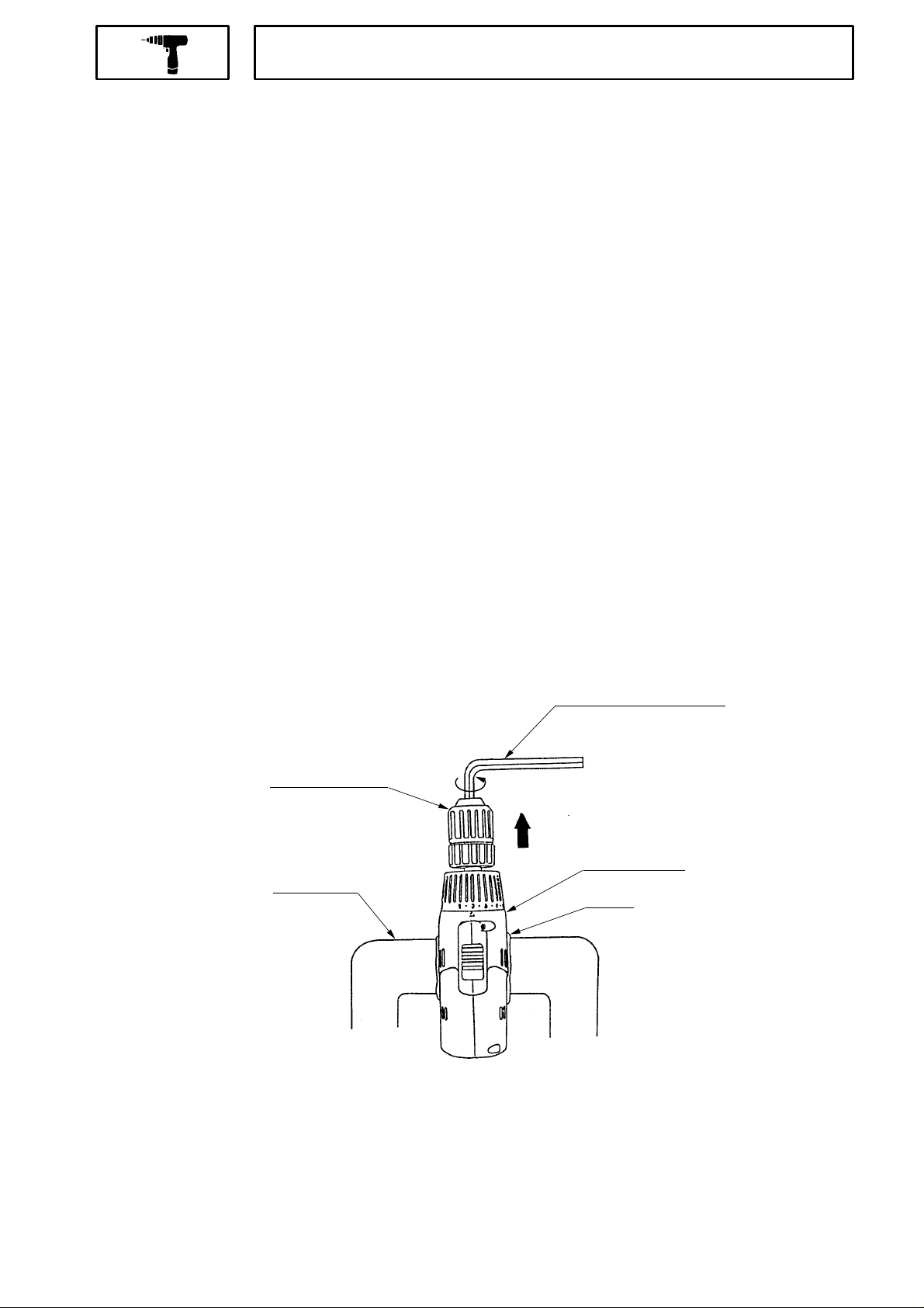
(1) Remove the Drill Chuck
(a) Slide the Drill Chuck
the jaws of the Drill Chuc k
Turn th e Special Screws M6 x 23
threaded.
(b) Fit the Hexagonal B ar Wrench for M10 into the Drill Chuc k
turning counterclockwise. If it is difficult to loosen, use a pipe or other tool.
(Note) Do not loosen by tapping with a hammer or the lik e.
Carry out operations (a) thr ough (b) with the dr iver unit c lamped in the s tock v ice. It is rec ommended to fit a
piece of cloth between the driv er unit and the vice to protect the Housing
[2]
. (See Fig. 6)
[2]
Sleeve to FREE and turn it counterclockwise (when viewed in front) to fully open
[2]
.
[1]
clockwise and remove them. Take care as they are left-hand
[2]
as indicated in Fig. 6 and rem ove it by
[31]
from scratching.
Hexagonal Bar Wrench
Drill Chuck
[2]
FREE
Stock Vice
(c) Align the number " 1" at the Cap
Housing
Cloth
Fig. 6
[4]
with the triangle mark at the Housings (A) and (B)
−1−
[31]
[31]
.
Page 2

(2) Removing Housing (B)
[31]
.
Remove the s even Tapping Screws D3 x 16
[31]
(B)
(3) With Housing (B)
while holding their battery loading sections .
[31]
removed, all the internal parts, assembled or separate, can be taken out as they are.
(a) Lift the entire content from Housing (A)
(b) Remove the Cap
[4]
and the Click Spring
(Note) Take care not to remove the Nut
(c) Turn the Motor
from the Rear Case
(d) Remove the Shift Arm
[37]
.
[26]
until a click sound is heard on the left side when viewed in the rear and remov e it
[17]
.
[37]
from the Rear Case
(e) Remove the four screws D3 x 12
(f) Remove the Washer (A)
Lock Ring
[12]
, and Steel Ball
six Needle Rollers (C)
[16]
, Ring Gear
[11]
[10]
and the twelve Steel Balls
[27]
secured to the driver unit. Gently open Housings (A) and
[31]
while holding the Motor
[8]
from the Front Case
[5]
from the Front Case
[17]
and remove the Shift Knob
[18]
connecting the Front Case
[13]
, Planet Gear (C)
[9]
[15]
in sequence from the Front Case
[11]
.
[26]
and Cap
[9]
.
.
[9]
and Rear Case
, Carrier
[14]
[9]
. Exercise care not to lose the
[4]
.
[38]
from the Shift Arm
[17]
.
, Needle Roller (C)
[10]
,
(4) Removing the Spring
Since the Nut
the Nut
[5]
[5]
removed, the Spring
[6]
and Washer (D)
is screwed into the Front Cas e
[6]
(Note) Avoid disassembling the Fr ont Cas e
[7]
[9]
and Washer (D)
[9]
.
, remove the Nut
[7]
can be removed from the Front Case
[5]
by turning counterc lockwis e. With
(5) Disassembly of the power s upply unit
(Note) Do not disconnect the three FET internal wires soldered to the DC Speed Contr ol Switc h
Disassembly of the Motor
[26]
, DC Speed Contr ol Switc h
[34]
, Motor Spacer
[25]
and Fin
step (3) can be carried out in the following procedure.
Disconnect the Internal Wires
With one Bind Screw M 3 x 7
[34]
and the Fin
[42]
can be taken apart.
[33]
[41]
Remove the two Machine Sc rews M4 x 6
When disconnecting the Internal Wires
be sure to remove the two Machine Screws M3 x 5
and
[36]
of Motor
[26]
with a soldering iron.
removed, the FET (Field Effect Transistor ) of DC Speed Control Switch
[29]
and take the Motor
[33]
and
[36]
[32]
of Motor
securing the flag-shaped terminal. (See Fig. 7)
[26]
and Motor Spacer
[26]
from the DC S peed Control Switch
1-1-2. Reassembly
[42]
[25]
[9]
.
[34]
.
removed in
apart.
[34]
,
Reassembly c an gener ally be carried out as the revers e of the disassembly procedure, with some items to be
noted as follows.
(1) Assembly of the power supply unit
(a) Be sure to perform wiring connection as indicated in the wir ing diagr am . (Fig. 7)
−2−
Page 3
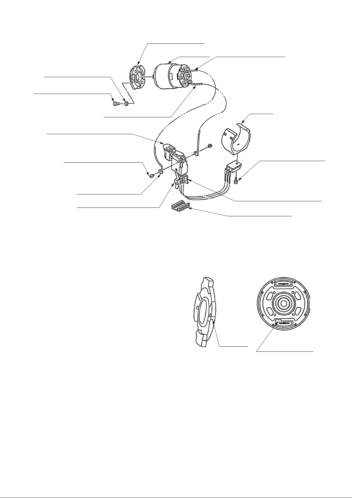
Motor Spacer
[25]
Spring Washer M4
Machine Screw M4 x 6
DC Speed Control Switch
Machine Screw M3 x 5
Flag-Shaped Terminal
Terminal Housing (A) ( + ) side
[30]
[29]
Internal Wire (Red)
[34]
[32]
[36]
Motor
[26]
Internal Wire (Black)
[42]
Fin
Bind Screw M3 x 7
Terminal Housing (B) ( - ) side
Terminal Support
[33]
[41]
[40]
Fig. 7
(Note) Do not deform the bendable legs of the FET attached to the DC Speed Control Switch
(b) Pay attention to the polarity of the Motor
when soldering the Internal Wires
[36]
to the Motor
the Motor
[26]
[26]
. The projected side of
is positive. (Fig. 8)
(Note) When installing the Motor Spac er
to the Motor
terminal of the Motor
[26]
, align the positive
[26]
marking on the Motor Spacer
[26]
[33]
and
[25]
with the
[25]
and
Marking
Projection: positive
Motor spacer
tighten with the Machine Screw M4 x 6
[29]
and the Spring Washer 4
(c) Apply grease (Hitachi motor greas e No. 29) to the pinion pressed into the Motor
[30]
.
Fig. 8
[26]
.
[34]
.
(2) Reassembly of the clutch unit
(a) Install the Washer (D)
[7]
When installing Washer (D)
projection on the Front Cas e
and the Spring
[7]
into the Front Case
[9]
.
[6]
into the Front Case
[9]
−3−
[9]
. (See Fig. 9)
, align the notch of Washer (D)
[7]
with the
Page 4

Z surface
Register marking (oo)
[5]
Nut
Spring
[6]
Washer (D)
Notch
Z surface
[7]
Projection Front Case
[9]
(b) Screw the Nut
Align the r egister mark ing (o) at the Nut
screwing on the Nut. Turn the Nut
marking (oo) at Nut
Make sure that the Z surfaces of Nut
Register marking (o)
Register marking
Register marking (oo)
Z surface Z surface Z surface
Register marking (o)
[5]
into the Front Case
[5]
is brought into alignment with the regis ter marking at the Front Cas e
Screwing start position
Z surface
Register marking
Fig. 9
[9]
. (See Fig. 10)
[5]
with the register marking on the Front Case
[5]
clockwise by about 1-1/4 turn and screw it in until the r egister
[9]
and start
[9]
[5]
and Front Case
[9]
are generally flush.
Screwing end position
Register marking (oo)
Register marking
Register marking (o)
[5]
[5]
.
(3) Reassembly of manual dr iv er mec hanis m
(a) Install the Lock Ring
[12]
into the Front Case
Assemble so that the projections on the Lock Ring
engage with the recesses in the Front Case
sure that the flat plane of the Lock Ring
Front Case
[9]
.
[9]
Fig. 10
[12]
[9]
.
[12]
[9]
. Make
faces the
−4−
[9]
[9]
[12] [10]
Recess
Projection
Fig. 11
Page 5

(b) Install the six Needle Rollers ( C). (See Fig. 11)
(Note) Exer cise c are to k eep the Loc k Ring's
free from grease when assembling manual driv er mechanism.
(4) Reassembly of the gearing
(a) Apply grease (Hitac hi m otor grease No. 29) to the mes hing parts of the gearing.
(b) Install the parts series from Steel Ball
Fig. 12)
(i) Note the direction of the gr oov e when installing the Slide Ring Gear
Motor side.
(ii) Install the Front Case
aligned with the Rear Case
[9] [11] [13] [14] [15] [16] [17] [18]
[9]
and Rear Case
[17]
marking. (See Fig. 15)
[12]
[11]
to Washer (B)
[17]
internal circumferenc e and Needle Rollers (C)
[24]
to the assembly from st ep (3). (See
[19]
together with the marking on the Front Case
[10]
so that the groove is on the
[9]
[19] [20] [21] [22] [21] [23] [24]
Install Washer (B)
recess in the Rear Case
Fig. 13)
[24]
Recess
in the Rear Case
[17]
, and turn Washer (B)
Fig. 12
[17]
with the projection of Washer (B)
[24]
clockwise until it can turn no further . (See
Projection
[24]
[24]
engaged with the
Fig. 13
−5−
Projection
Page 6
(c) Install the Click Spring
[8]
and Cap
[4]
into the assembly from step ( b) . (See Fig. 14)
(i) Insert the projection of the Crick Spring
(ii) Install the Cap
[4]
.
One of the three projections on the Nut
Assemble the Nut and Cap together with the wider projection of the Nut
recess of the Cap
[4]
. (The wider rec ess in the Cap
from outside.)
[4]
Projection
Hole
[8]
[8]
into the hole in the Front Cas e
[5]
and one of the three recesses inside the Cap
[9]
.
[5]
[4]
is positioned at the number "1" when viewed
"1"
Wider projection
Recess
Cap
[4]
are wider.
engaged in the wider
Wider projection
Nut
Projection
(d) Install the Shift Ar m
[37]
(i) With the ridge at the Shift Arm
assembly from step (c).
Then insert the projection on the Shift Ar m
that the projection is fitted into the recess in the Slide Ring Gear
[17]
.
(ii) When installing the Shift Knob
[38]
is on the Motor side with the Shift Arm
[37]
and the Shift Knob
[37]
set on the Motor side, first ins tall them on the unmar k ed side of the
[38]
into the Shift Arm
Fig. 14
[38]
into the assembly from step (c).
[37]
into the hole in the Rear Case
[19]
mounted within the Rear Cas e
[37]
, note that the LOW mark on the Shift Knob
[37]
engaged with the recess in the Shift Knob
[37]
Hole
Ridge
[17]
and make sure
[38]
.
Marking
Recess
Fig. 15
−6−
Page 7

(e) Install the assembly in (1) and the assembly from (d) together. (See Fig. 16)
Fit the projection on the Motor Spacer
the marking on assembly (d) is aligned with the marking on the Motor Spacer
Spacer clockwise when v iewed from the rear of the Motor
installation, make sure that the pinion pressed into the M otor
properly.
[25]
into the recess in the Rear Case
[26]
Fig. 16
until it can no further tur n. During
[26]
[17]
and Planet Gear (A)
Projection
Recess
while making sure that
[25]
, and turn the Motor
[21]
mesh
(f) Install the Pushing Button
(g) Install the assembly from (e) into Housing (A)
Note that the projections on the Front Case
Housing (A)
Fig. 18)
[35]
[31]
and the projection on Housing (A)
[35]
into Housing (B)
[31]
[31]
. (See Fig. 17)
[31]
.
[9]
and the Motor Spacer
[31]
is engaged in the groove in the Cap
[31]
[25]
are engaged in the recess in
Cap groove
[4].
(See
Fig. 17
Set the assembly from (f) to Housing (A)
Projection
Projection
Recess
Fig. 18
[31]
and secure it with the seven Tapping Screws D3 x 16
−7−
[27]
.
Page 8

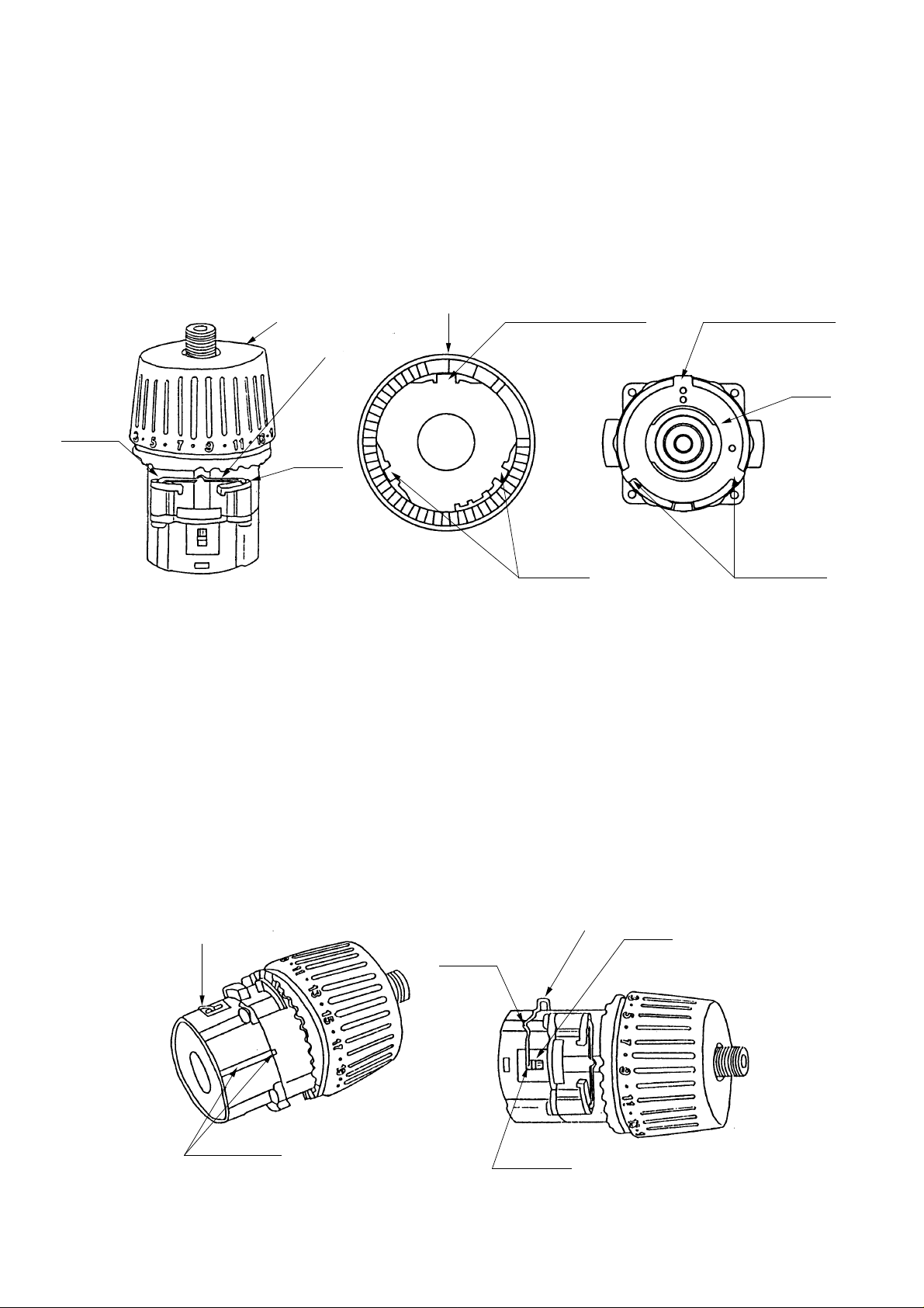
(i) Verify proper operation of the Cap
[4]
.
When the assembly procedure up to step (g) is complete, make sure that the number "1"on Cap
the drill mark " " on the Housing are in alignment with the triangle mark on the Housing and that the
[4]
Cap
If the cap motion is jer k y or loose, check to see if the Click Spring
"1" on the Cap
correctly re-install the Cap
(h) Clamp the ass embly from step (g) in a stoc k vic e, install the Drill Chuck
Screw M6 x 23
(5) Other precautions during as s embly
(a) When the assembly procedur e is c omplete, make sure that the turning direction of the Drill Chuc k
corresponds to the position of the Pushing Button
the (R)-marked side, the Drill Chuck
the drill). Also make sure that the Drill Chuck turning speed switches between High and Low by
switching the Shift Knob
Make sur e that the run-out of the Drill Chuck
distance of 100 mm from the chuck end.
is able to turn at a moderate speed.
[4]
or drill mark " " should not r each the tr iangle m ar k ing on Hous ing (A), (B)
[4]
referring to step (4) (c ) as it is improperly installed.
[1]
.
[2]
should turn clockwise when viewed from the rear ( handle end of
[38]
.
[8]
is properly installed. If the number
[2]
and tighten with the Special
[35]
. When the Pus hing Button
[2]
holding a 12 mm dia. test bar is below 0.8 mm at a
[35]
is pressed from
[4]
and
[31]
[2]
,
(b) While Housings (B)
difference in that the battery loading section at the DS 10DV2 Housing (B)
projection, with no suc h projection at the battery loading section of the DS 13DV2 Housing. Exerc ise
care when carrying out assembly. (See Fig. 19)
Projection
[31]
of DS 13DV2 and DS 10DV2 are of the same external shape, there is a
[31]
is formed with a
Housing (B)
Battery loading section
DS 10DV2 DS 13DV2
Fig. 19
−8−
Page 9

(c) Tightening torque of each screw is giv en below.
Tapping Screw D3 x 16
Special Screw M6 x 23
Bind Screw M3 x 7
Machine Screw M3 x 5
Machine Screw M4 x 6
Drill Chuck
Screw D3 x 12
1-2. Precautions in Disassembly and Reassembly of Battery
Please refer to the Technical Data and Service Manual (No. E878) for precautions on disassembly and
reassembly of the battery c har ger UC 12YD.
[27]
1.08 - 1.86 Nm (11 - 19 kgfcm, 9.6 - 16.5 in-lbs.)
[1]
3.92 - 4.90 Nm (40 - 50 kgfcm, 34.7 - 43.4 in-lbs.)
[41]
0.49 - 0.78 Nm (5 - 8 kgfcm, 4.3 - 6.9 in-lbs.)
[32]
0.29 - 0.39 Nm (3 - 4 kgfcm, 2.6 - 3.5 in-lbs.)
[29]
1.08 - 1.86 Nm (11 - 19 kgfcm, 9.6 - 16.5 in-lbs.)
[2]
17.6 - 21.6 Nm (180 - 220 kgfcm, 156 - 191 in-lbs.)
[18]
0.59 - 0.98 Nm (6 - 10 k gfc m , 5.2 - 8.7 in-lbs.)
−9−
Page 10

2. STANDARD REPAIR TIME (UNIT) SCHEDULES
Model
DS 13DV2
Fixed
Variable
General Assembly
Fixed Cost
Keyless chuck 0 min.
Others 20 min.
10 20 30 40 50 60
Work Flow
Housing
(A)(B)Set
Motor
Spacer
DC speed
control switch
Pushing button
Shift arm
Shift knob
Fin
<Gear Box
Ass'y>
Keyless chuck
Motor spacer
Washer (B)
First ring gear
Planet gear
(A) set
Pinion (B)
Pinion (C)
Slide ring gear
Cap
Nut
Spring
Washer (D)
Front case
Needle roller
(C) set
Steel ball
Lock ring
Carrier
Planet gear
(C) set
Washer (A)
Rear case
−10−
 Loading...