

Page 1
充电式起子电钻
Cordless Driver Drill
DS 10DAL
中 文
English
保留备用
Keep for future reference
使用说明书
Handling instructions
Page 2

中文
目次
电动工具通用安全警告 .............................2
充电式起子电钻安全警告..........................4
其它安全警告...................................................4
锂离子电池使用注意事项..........................5
符号.......................................................................6
标准附件.............................................................7
用途.......................................................................7
规格.......................................................................7
电池的拆卸和安装方法...............................8
充电.......................................................................8
操作....................................................................10
操作注意事项................................................14
维护和检查.....................................................15
选择附件..........................................................16
电动工具通用安全警告
警告!
阅读所有警告和所有说明。
不遵照以下警告和说明会导致电击、着火和/或严重伤害。
保存所有警告和说明书以备查阅。
在所有下列的警告中术语“电动工具”指市电驱动(有线)电动工具或电池驱动(无
线)电动工具。
1) 工作场地的安全
a) 保持工作场地清洁和明亮。
混乱和黑暗的场地会引发事故。
b) 不要在易爆环境,如有易燃液体、气体或粉尘的环境下操作电动工具。
电动工具产生的火花会点燃粉尘或气体。
c) 让儿童和旁观者离开后操作电动工具。
注意力不集中会使操作者失去对工具的控制。
2) 电气安全
a) 电动工具插头必须与插座相配。绝不能以任何方式改装插头。需接地的
电动工具不能使用任何转换插头。
未经改装的插头和相配的插座将减少电击危险。
b) 避免人体接触接地表面,如管道、散热片和冰箱。
如果你身体接地会增加电击危险。
c) 不得将电动工具暴露在雨中或潮湿环境中。
水进入电动工具将增加电击危险。
d) 不得滥用电线。绝不能用电线搬运、拉动电动工具或拔出其插头。使电
线远离热源、油、锐边或运动部件。
受损或缠绕的软线会增加电击危险。
2
Page 3

e) 当在户外使用电动工具时,使用适合户外使用的外接软线。
适合户外使用的软线将减少电击危险。
f) 如果在潮湿环境下操作电动工具是不可避免的,应使用剩余电流动作保
护器(RCD)。
使用RCD可减小电击危险。
3) 人身安全
a) 保持警觉,当操作电动工具时关注所从事的操作并保持清醒。当你感到
疲倦,或在有药物、酒精或治疗反应时,不要操作电动工具。
在操作电动工具时瞬间的疏忽会导致严重人身伤害。
b) 使用个人防护装置。始终佩戴护目镜。
安全装置,诸如适当条件下使用防尘面具、防滑安全鞋、安全帽、听力
防护等装置能减少人身伤害。
c) 防止意外起动。确保开关在连接电源和/或电池盒、拿起或搬运工具时
处于关断位置。
手指放在已接通电源的开关上或开关处于接通时插入插头可能会导致危
险。
d) 在电动工具接通之前,拿掉所有调节钥匙或扳手。
遗留在电动工具旋转零件上的扳手或钥匙会导致人身伤害。
e) 手不要伸展得太长。时刻注意立足点和身体平衡。
这样在意外情况下能很好地控制电动工具。
f) 着装适当。不要穿宽松衣服或佩戴饰品。让衣服、手套和头发远离运动
部件。
宽松衣服、佩饰或长发可能会卷入运动部件中。
g) 如果提供了与排屑、集尘设备连接用的装置,要确保它们连接完好且使
用得当。
使用这些装置可减少尘屑引起的危险。
中文
4) 电动工具使用和注意事项
a) 不要滥用电动工具,根据用途使用适当的电动工具。
选用适当设计的电动工具会使你工作更有效、更安全。
b) 如果开关不能接通或关断工具电源,则不能使用该电动工具。
不能用开关来控制的电动工具是危险的且必须进行修理。
c) 在进行任何调节、更换附件或贮存电动工具之前,必须从电源上拔掉插
头和/或使电池盒与工具脱开。
这种防护性措施将减少工具意外起动的危险。
d) 将闲置不用的电动工具贮存在儿童所及范围之外,并且不要让不熟悉电
动工具或对这些说明不了解的人操作电动工具。
电动工具在未经培训的用户手中是危险的。
3
Page 4

中文
e) 保养电动工具。检查运动件是否调整到位或卡住,检查零件破损情况和
影响电动工具运行的其他状况。如有损坏,电动工具应在使用前修理好。
许多事故由维护不良的电动工具引发。
f) 保持切削刀具锋利和清洁。
保养良好的有锋利切削刃的刀具不易卡住而且容易控制。
g) 按照使用说明书,考虑作业条件和进行的作业来使用电动工具、附件和
工具的刀头等。
将电动工具用于那些与其用途不符的操作可能会导致危险。
5) 电池式工具使用和注意事项
a) 只用制造商规定的充电器充电。
将适用于某种电池盒的充电器用到其他电池盒时会发生着火危险。
b) 只使用配有特制电池盒的电动工具。
使用其他电池盒会发生损坏和着火危险。
c) 当电池盒不用时,将它远离其他金属物体,例如回形针、硬币、钥匙、钉子、
螺钉或其他小金属物体,以防一端与另一端连接。
电池端部短路会引起然烧或火灾。
d) 在滥用条件下,液体会从电池中溅出 ;避免接触。如果无意间碰到了,
用水冲洗。如果液体碰到了眼睛,还要寻求医疗帮助。
从电池中溅出的液体会发生腐蚀或燃烧。
6) 维修
a) 将你的电动工具送交专业维修人员,使用同样的备件进行修理。
这样将确保所维修的电动工具的安全性。
注意!
不可让儿童和体弱人士靠近工作场所。
应将不使用的工具存放在儿童和体弱人士接触不到的地方。
充电式起子电钻安全警告
1. 在执行切割附件或紧固件会接触到暗线的操作时,通过绝缘的抓紧表面拿住
电动工具。
接触“带电”电线的切割附件或紧固件会使电动工具的裸露金属部件“带电”,
并可能使操作员遭到电击。
其它安全警告
1. 确保要钻入的区域完全没有任何障碍物,包括电线、水或煤气管道。钻入上
述事物可能导致触电、短路、煤气泄漏或可能引发造成严重事故、伤害的其
他风险。
2. 确保在操作期间牢固地握住工具。否则,可能导致事故或伤害。
4
Page 5

中文
3. 紧固工件。使用夹紧装置或台钳夹紧工件,远比手动夹紧更为牢固。
4. 准备和检查工作环境。请遵循相关注意事项,检查工作环境是否适用。
5. 勿让杂质进入电池连结口内。
6. 切勿拆卸电池与充电器。
7. 切勿使电池短路。使电池短路将会造成很大的电流和过热,从而烧坏电池。
8. 请勿将电池丢入火中。
电池受热将会爆炸。
9. 充电后电池寿命太短不够使用时,请尽快将电池送往经销店。请勿将用过的
电池乱丢。
10. 请勿将异物插入充电器的通风口。
若将金属异物或易燃物插入通风口的话,将会引起触电事故或使充电器受损。
11. 工具过载时,电机可能停止运行。发生此类情况时,释放工具开关,消除过
载原因。
12. 在寒冷环境(0℃以下)中使用电池有时会造成旋紧扭矩变弱以及作业量的
减少。但是,这只是暂时现象,在电池变热后将会恢复正常。
13. 为了防止因忘记关闭 LED 灯而使电池耗电,约在 15 分钟后灯会自动关闭。
锂离子电池使用注意事项
为延长使用期限,锂离子电池备配停止输出的保护功能。
若是在使用本产品时发生下列 1 至 3 的情况,即使按下开关,马达也可能停止。
这并非故障,而是启动保护功能的结果。
1. 在残留的电池电力即将耗尽时,马达会停止。
在这种情况下,请立即予以充电。
2. 若工具超过负荷,马达亦可能停止。在这种情况下,请松开工具的开关,试
着消除超过负荷的原因。之后您就可以再度使用。
3. 若电池在过载工作情况下过热,电池电力可能会中止。
在这种情况下,请停止使用电池,让电池冷却。之后您就可以再度使用。
此外,请留心下列的警告及注意事项。
警告!
为防止发生电池漏电、发热、冒烟、爆炸及提前点燃,请确保留意下列事项。
1. 确保电池上没有堆积削屑及灰尘。
○ 在工作时确定削屑及灰尘没有掉落在电池上。
○ 确定所有工作时掉落在电动工具上的削屑和灰尘没有堆积在电池上。
○ 请勿将未使用的电池存放在曝露于削屑和灰尘的位置。
○ 在存放电池之前,请清除任何可能附着在上面的削屑和灰尘,并请切勿将它
与金属零件(螺丝、钉子等)存放在一起。
2. 请勿以钉子等利器刺穿电池、以铁锤敲打、踩踏、丢掷电池,或将其剧烈撞击。
3. 切勿使用明显损坏或变形的电池。
4. 使用电池时请勿颠倒电极。
5
Page 6

中文
5. 请勿直接连接电源插座或汽车点烟器孔座。
6. 请依规定方式使用电池,切勿移作他用。
7. 如果已过了再充电时间,电池仍无法完成充电,请立即停止继续再充电。
8. 请勿将电池放置于高温或高压处,例如微波炉、烘干机或高压容器内。
9. 在发觉有渗漏或异味时,请勿接近远离火源。
10. 请勿在会产生强烈静电的地方使用。
11. 如有电池渗漏、异味、发热、褪色或变形,或在使用、充电或存放时出现任
何异常,请立即将它从装备或电池充电器拆下,并停止使用。
注意!
1. 若电池渗漏出的液体进入您的眼睛,请勿搓揉眼睛,并以自来水等干净清水
充分冲洗,立刻送医。
若不加以处理,液体可能会导致眼睛不适。
2. 若液体渗漏至您的皮肤或衣物,请立即以自来水等清水冲洗。
上述情况可能会使皮肤受到刺激。
3. 若初次使用电池时发现生锈、异味、过热、褪色、变形及/或其它异常情况时,
请勿使用并将该电池退还给供货商或厂商。
警告!
如果导电异物接触到锂离子电池的端子,电池可能短路,并导致火灾。
存放锂离子电池时,请务必遵循下列注意事项。
○ 切勿在存放盒中放置导电的残片,钉子,以及导线,如铁线和铜线。
○ 为防止发生短路,应将电池装入工具中或者在存放时牢固地插入电池盖,直
至看不到通风口。
符号
警告!
如下所示的符号用于本机。使用前请务必理解其含意。
阅读所有安全警告和所有指示。
6
Page 7
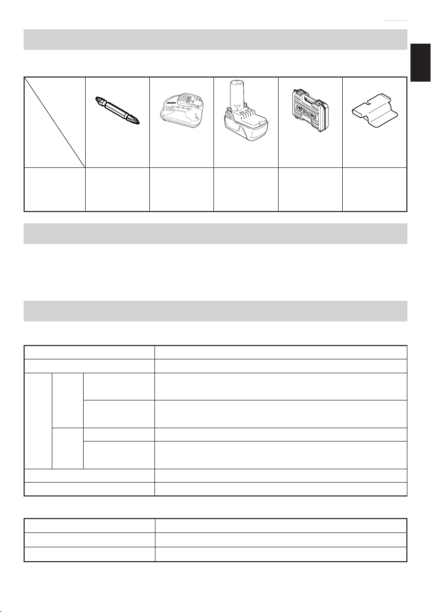
标准附件
除了主机(1 台)外,产品包中还包括表中所列的附件。
中文
十字槽头
螺丝刀头
DS10DAL 1 1 1 或 2 1 1
充电器
UC10SL2
锂离子电池
BCL1015
箱子 电池盖
用途
○ 旋紧和拆除机用螺丝、木螺丝、自攻螺丝等。
○ 钻各种金属。
○ 钻各种木料。
规格
电动工具
型式 DS10DAL
无负荷速度 (低 / 高) 0 - 350 / 0 - 1300 转 / 分
木料
(厚 18 mm)
钻孔
金属
能力
电池 BCL1015 :锂离子 10.8 V(1.5 Ah 3 节 )
重量 1.0 kg
(厚 1.6 mm)
机用螺丝 6 mm
螺丝
紧固
木螺丝
5.8 mm(直径)× 45 mm(长)
29 mm
钢材 :10 mm
铝 :12 mm
(应有导孔)
充电器
型式 UC10SL2
充电电压 10.8 V
重量 0.35 kg
7
Page 8
中文
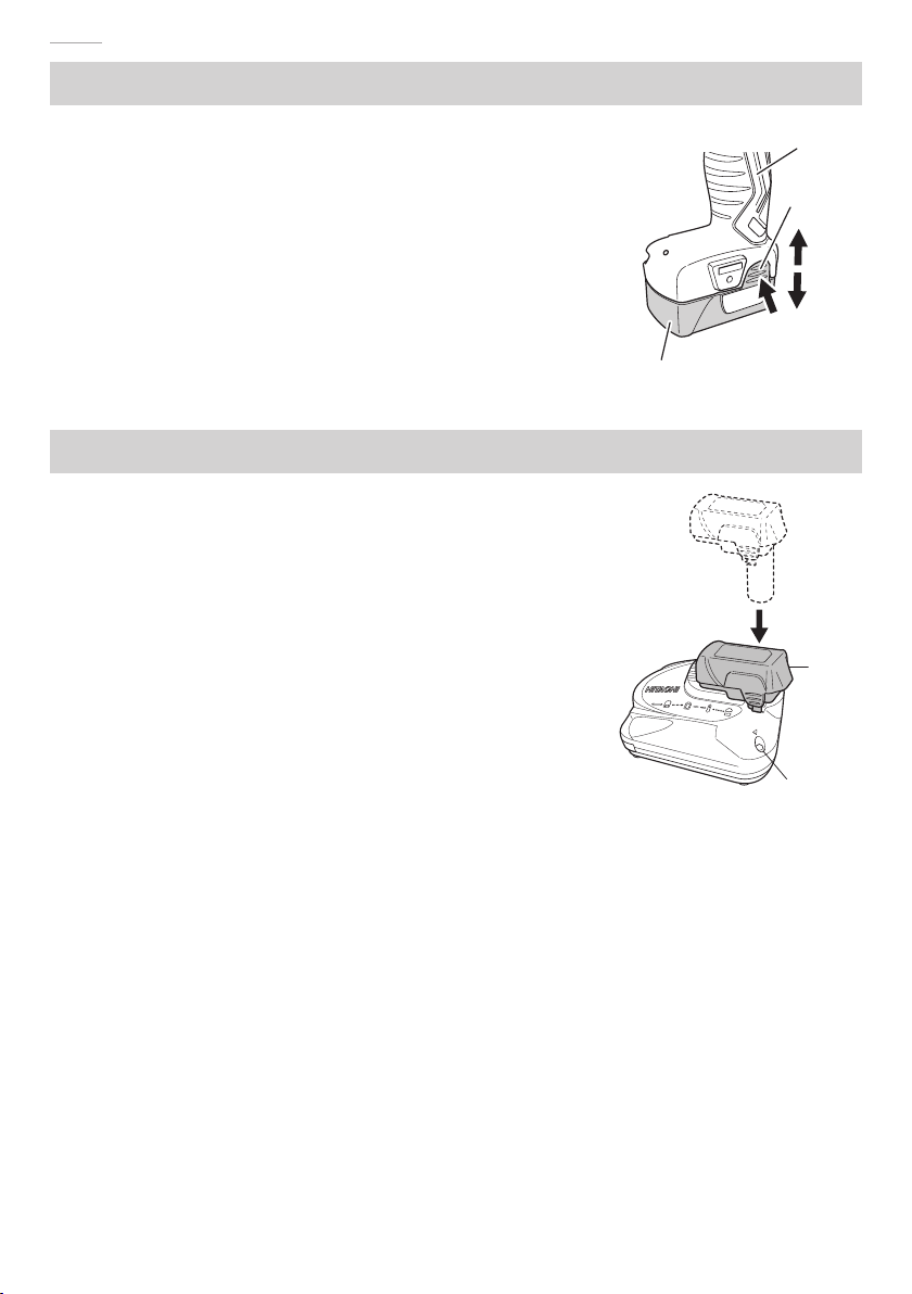
电池的拆卸和安装方法
○ 如何安装电池。
将电池对准工具手柄内的凹槽,然后滑入到适当
位置。
继续插入直至锁定到一个位置,且发出一声轻轻
的咔哒声,如果未如此操作,那么电池可能会从
工具中意外坠落,导致您或者您周围的人员受伤
(图1)。
○ 如何拆卸电池。
在按下电池闭锁(2 件)的同时,从工具手柄中
拆下电池(图1)。
充电
使用电动工具之前,按下述方法将电池进行充电。
1. 将充电器的电源线连接到插座。
将充电器插头连接到插座时,指示灯闪烁红色(间
隔为 1 秒)。
2. 将电池插入充电器。
如图 2 所示,将电池稳稳地插入充电器直至其接
触到充电器的底部。
3. 充电
将电池插入充电器后,充电器上的指示灯将持续
点亮呈红色。
电池完全充电后,指示灯将闪烁呈红色(以 1 秒
的间隔)(参照表 1)。
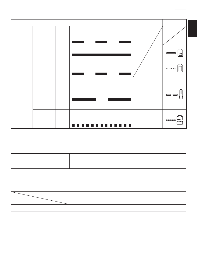
(1) 指示灯显示
根据充电器或电池的情况,指示灯的显示如表 1 所示。
手柄
插销
插入
拔出
按
电池
图1
电池
指示灯
图 2
8
Page 9
充电前 闪烁
中文
表 1
指示灯的显示 标记符号
点亮 0.5 秒钟,不点亮
0.5 秒钟(熄灭 0.5 秒钟)
充电时 点亮
充电完成 闪烁
指示灯
(红色)
过热而等
待
无法充电 闪烁
(2) 关于电池的温度
电池的温度如表 2 所示,在充电前应使已发热的电池冷却片刻。
表 2 电池充电范围
电池 可以对电池进行充电的温度
BCL1015 0℃
(3) 关于充电时间
由充电器和电池共同决定,充电时间变化如表3所示。
闪烁
连续点亮
点亮 0.5 秒钟,不点亮
0.5 秒钟(熄灭 0.5 秒钟)
点亮 1 秒钟,不点亮
0.5 秒钟(熄灭 0.5 秒钟)
点亮 0.1 秒钟,不点亮
0.1 秒钟(熄灭 0.1 秒钟)
-
50℃
电池过热。
无法充(电
池冷却后开
始进行充
电)。
电池或充电
器有问题。
表 3 充电时间(20℃下)
充电器
电池
BCL1015 约 30 分钟
注:
充电时间可能根据环境温度和电压而有变化。
4. 从电源插座拔下充电器的电源线。
5. 握紧充电器并取出电池。
注:
充电后,先将电池从充电器中取出,然后妥善保存。
UC10SL2
9
Page 10
中文
注意!
○ 如果电池长时间放置在阳光直接照射的地方或者刚刚使用完毕时,电池会
变热。如果此时对电池充电,充电器上的指示灯会点亮 1 秒钟,不点亮
0.5 秒钟(熄灭 0.5 秒钟)。
在此情况下,先让电池冷却下来,然后再充电。
○ 指示灯闪动时(以 0.2 秒钟的间隔),请检查并取出充电器电池接口处的任
何异物。若无异物,则可能电池或充电器发生故障。请带去经授权的维修中
心检查。
○ 因内置的微机需要约 3 秒钟才能确认正用 UC10SL2 进行充电的电池已被取
出,因此请待 3 秒钟后再重新插入电池继续充电。如果在不到 3 秒内就插
入电池,则电池可能充电不正常。
操作
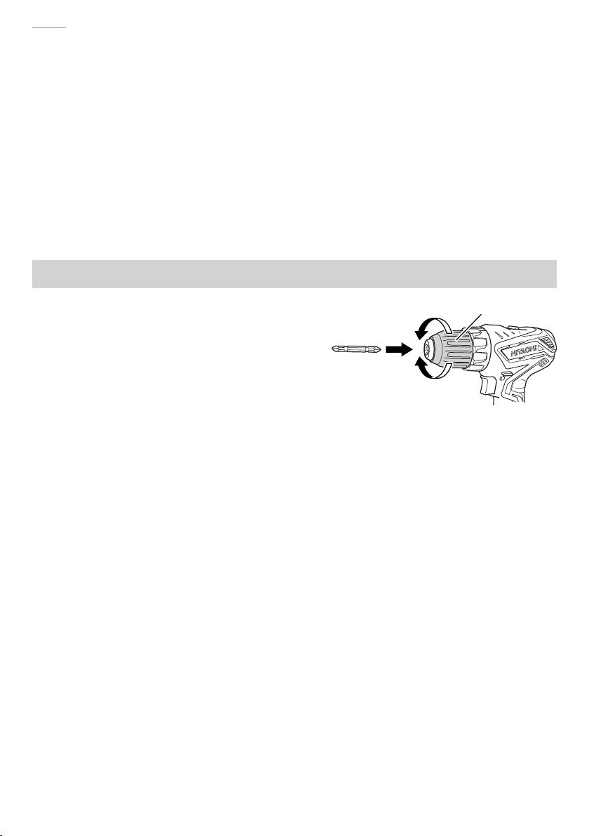
1. 钻头的安装和拆卸
(1) 安装钻头。
通过向左转动(按前视图中的逆时针
方向转动)打开无键夹盘的夹具,可
以拧松导套。在将起子钻头等插入到
无键锤钻夹盘之后,通过向右转动(按
前视图中的顺时针方向转动)可拧紧
导套。(请参照图3)
注:
如果导套在操作期间变得松动,那么请拧紧。
当导套已拧紧的时候,旋紧力将变得更强。
2. 拆卸钻头
通过向左转动(按前视图中的逆时针方向转动)可以拧松导套,然后可以取
出钻头等(请参照图3)。
旋松
旋紧
导套
图3
注意!
在将钻头装入无键夹盘的时候,请拧紧。如果导套未拧紧,那么钻头可能会
滑动或者坠落,导致人员受伤。
注:
应松动夹盘,否则将难以移动导套。
用钳子或者类似工具夹住安装在无键夹盘中的钻头。
将离合器转盘位置设定至“1-11”,然后打开开关。马达将开始运转。
最后,向左旋转导套,直至其松动。
3. 确认已正确地安装了电池。
10
Page 11

4. 检查旋转方向。
L
R
L
R
L
推动选择按钮的 R 侧,钻头将以顺时针
方向旋转(从后侧部的视角来看)。
推动选择按钮的 L 侧,钻头将以逆时针
方向旋转(请参照图4)。(机身上附有
和R标记。)
○ 在按下触发器开关的时候,工具将旋转。
在释放开关的时候,工具将停止旋转。
○ 通过改变拉动触发器开关的力度,可以
控制钻头的旋转速度。在轻微拉动触发
器开关的时候,速度较低,随着拉力增
加,速度也将随之提高。
○ 在释放触发器开关的时候,将利用制动
装置,立即停止运转。
5. 改变旋转速度。
请用变速开关来改变转速。请按箭头方
向移动变速开关(图5和图6)。
如果变速开关被设在“LOW”位置,钻
头则低速旋转 ;如果变速开关被设在
“HIGH”位置,钻头则高速旋转。
选择按钮
标记
中文
触发器开关
标记
图4
变速开关
高速
图5
变速开关
注意!
○ 当用变速开关改变转速时,应确保电源
开关已被断开。
如果在马达旋转过程中改变速度,则会
损坏齿轮。
○ 在需要较大的应力进行操作(下图中所
示的操作)的时候,将变速开关设置为
“LOW”。如果设置为“HIGH”并使用本
机,那么可能会导致马达烧坏或者过早
出现故障。
6. 确认离合器转盘位置(请参照图7)
可以根据离合器转盘的位置,即设置离合器转盘的位置,调节本装置的旋紧
转矩。
(1) 在将本装置作为螺丝起子使用时,将离合器转盘上的“1, 3, 5…21”中的某
个数字或黑点与机身外侧上的三角标记对齐。
(2) 在将本装置作为钻机使用时,将离合器转盘钻机标记“ ”与机身外侧上
的三角标记对齐。
弱
强
11
低速
图6
离合器转盘
图7
三角标记
标记
Page 12

中文
注意!
○ 离合器转盘不能设在数字“1、3、5……21”
之间或黑点之间。
○ 当离合器转盘位于“21”和钻机标记“ ”
之间时,请勿使用本机,否则会造成损坏。
(请参照图 8)
7. 旋紧转矩的调节
(1) 旋紧转矩
旋紧转矩的强度应与螺丝直径相对应。在施加过大的应力时,螺丝头可能会
受损或者导致人员受伤。务请按螺丝直径来调节离合器转盘的位置。
(2) 旋紧转矩指示(请参照第 11 页的图 7)
旋紧转矩根据螺丝的类型以及待紧固的材料而有所不同。
本机采用离合器转盘上的“1、3、5……21”以及黑点来指示旋紧转矩。旋
紧转矩在位置“1”时最小,在最大数字处时最大。
(3) 调节旋紧转矩(请参照第 11 页的图 7)
转动离合器转盘并使离合器转盘上的数字“1、3、5……21”或点与机身外
侧上的三角标记对齐。按所需转矩将离合器转盘向小转矩或大转矩方向调节。
标记
三角标记
线
图8
注意!
○ 当把本机用作钻机时,马达可能会被锁住而停止转动。请在使用起子电钻机
过程中不要锁住马达。
○ 如果马达被锁定,则请立即关闭电源。如果马达被锁定一段时间,则马达或
电池可能烧毁。
○ 如果冲击时间过长,螺丝可能会因旋紧力过大而折断。
8. 使用照明灯
拉动触发器开关,可以打开照明灯。在持续拉
动触发器开关的时候,该照明灯将保持照明。
在释放触发器开关后,照明灯将熄灭(图9)。
注意!
请勿直视照明灯,否则可能导致损伤眼睛。
12
触发器
开关
照明灯
图9
Page 13

中文
9. 使用范围和建议
表 4 给出了基于本机机械结构的各种可用工作范围。
表4
工作 离合器转盘位置 建议
木材
钻孔
螺丝紧固
铝材
小螺丝 1 - 21 使用与螺丝直径相配的钻头或套筒。
木螺丝
1-
用于钻孔。钢材
钻好导孔后使用。
注意!
○ 请在使用起子电钻机过程中不要锁住马达。
如果马达被锁定,则请立即关闭电源。
如果马达被锁定一段时间,则马达或电池可能烧毁。
○ 切勿过度拧紧,因为螺丝头将受损。
10. 如何选择旋紧转矩和旋转速度
注意!
表 5 中给出的选择例子应作为一般标准来考虑。在实际工作中使用的都是不
同类型的紧固螺丝和受紧固的材料,因此理应进行适当的调节。
表 5
转速选择(变速开关的位置)
LOW ( 低速 ) HIGH ( 高速 )
用于直径在 6 mm 或以
下的螺丝。
用于公称直径在 3.8 mm
或以下的螺丝。
用于直径在 12 mm 或
以下。
-
用于采用金属加工钻头
的钻孔作业。
钉入
钻孔
用途
机用螺丝 1 - 21
木螺丝
木质
钢铁
离合器
转盘位置
1-
用于直径在 6 mm 或以
下的螺丝。
用于公称直径在 5.8 mm
或以下的螺丝。
用于直径在 29 mm 或
以下。
13
Page 14

中文
操作注意事项
1. 连续作业后须让装置休息片刻
在连续进行紧固螺栓作业后以及在更换电池后,请让本装置暂停作业 15 分
钟左右。如果在更换电池后立刻开始作业,马达和开关等的温度将会升高,
结果导致烧毁。
2. 速度控制开关的使用注意
本开关内置有一个电路,可以无级调节旋转速度。因此,如果仅轻微拉动触
发器开关(转速较低),且马达停止运转而螺丝持续钉入,则电路零件可能
会过热且受到损坏。
3. 使用适合螺丝的拧紧时间
螺丝的适当旋紧转矩因螺丝的材料和尺寸,以及待紧固的材料等而异,所以
请使用适合螺丝的拧紧时间。尤其是,如果在螺丝直径小于 8 mm 的情况下,
拧紧时间较长,则存在螺丝受损的风险,所以请事先确认拧紧时间和拧紧扭
矩。
4. 以适合于螺栓冲击应力的拧紧扭矩操作
螺母或者螺栓的最佳拧紧扭矩因螺母或者螺栓的材料和尺寸而有所不同。
对于较小的螺栓,过大的拧紧扭矩会导致螺栓伸展或者受损。拧紧扭矩将随
着操作时间的延长而成比例的增加。请使用适合于螺栓的正确操作时间。
5. 确认旋紧转矩
如下因素会导致旋紧转矩减小。所以,应在开展工作之前利用一个手动扭矩
扳手拧紧一些螺栓,以确认实际所需的旋紧转矩。影响旋紧转矩的因素如下
所示。
(1) 电压
在达到放电极限的时候,电压将减小,而旋紧转矩将降低。
(2) 操作时间
在操作时间延长的时候,旋紧转矩将增加。但是旋紧转矩不会增加至超过一
个特定值,即使工具已运转了较长时间也是如此。
(3) 螺栓的直径
旋紧转矩因螺栓的直径而存在不同。通常而言,直径较大的螺栓需要的旋紧
转矩更大。
(4) 旋紧条件
旋紧转矩因螺栓的变矩系数、类别和长度而存在不同,即使所用螺栓的螺纹
大小相同亦如此。此外,旋紧转矩还因待紧固的螺栓所穿过的工作件的表明
条件有所不同。在螺栓和螺母一起转动的时候,转矩大幅降低。
14
Page 15

中文
维护和检查
1. 检查工具
由于使用已经钝化的工具会降低效率并可能引起马达故障,因此一旦注意到
磨损情况,就应及早磨快或更换工具。
2. 检查安装螺钉
要经常检查安装螺钉是否紧固妥善。若发现螺钉松了,应立即重新扭紧,否
则会导致严重的事故。
3. 电动机的维护
电动机绕线是电动工具的“心脏部”应仔细检查有无损伤,是否被油液或水
沾湿。
4. 清理外部
冲击电钻机沾污时,用干软布或沾肥皂水的布擦拭。切勿使用氯溶液、汽油
或稀释剂,以免塑胶部分溶化。
5. 收藏
冲击电钻机应收藏于温度低于 40℃和小孩拿不到的地方。
注:
在电池长期存放(3 个月或更长)后务必给电池完全充电。如果长期存放后
使用,容量小的电池可能无法充电。
注:
存放锂离子电池
在存放前请确保锂离子电池已完全充电。
电池在低电量的状态下长时间存放,可能会导致电池性能劣化,使用时间明
显减少或无法进行充电。
但是,即使是使用时间明显减少的电池,通过反复充电和使用2~5次,有
时也可恢复使用时间。
若反复充电和使用后电池的使用时间仍非常短,请认作为电池已达到了使用
寿命并更换新的电池。
注意!
在操作和维修电动工具时,必须遵守贵国制定的安全的有关规则和标准。
关于日立牌无线电动工具的重要通知 :
请确保始终使用我们指定的正版电池。如果使用我们指定以外的电池,或对电
池进行拆卸和改动(例如拆卸和更换电池组件或其他内部部件),那么我们无
法保证我们无线电动工具的安全性和使用性能。
15
Page 16

中文
选择附件
根据特定作业选择适合的附件。
有关详细信息请联系日立授权服务中心。
产品编号:331069
BCL1015:电池
产品编号:331086
电池盖
产品编号:983006
十字槽头螺丝刀头
产品编号:336642
箱子
UC10SL2
充电器
产品编号:337131
挂钩组
16
Page 17

English
CONTENTS
GENERAL POWER TOOL SAFETY WARNINGS ........................................ 17
CORDLESS DRIVER DRILL SAFETY WARNINGS .................................... 20
ADDITIONAL SAFETY WARNINGS ............................................................. 20
CAUTION ON LITHIUM-ION BATTERY .......................................................20
SYMBOL .......................................................................................................22
STANDARD ACCESSORIES ....................................................................... 22
APPLICATIONS ............................................................................................22
SPECIFICATIONS ........................................................................................ 23
REMOVAL AND INSTALLATION METHOD OF BATTERY..........................23
CHARGING ..................................................................................................24
OPERATION .................................................................................................26
OPERATIONAL CAUTIONS .........................................................................29
MAINTENANCE AND INSPECTION ............................................................30
SELECTING ACCESSORIES .......................................................................31
GENERAL POWER TOOL SAFETY WARNINGS
WARNING
Read all safety warnings and all instructions.
Failure to follow the warnings and instructions may result in electric shock, fi re and/or serious
injury.
Save all warnings and instructions for future reference.
The term “power tool” in the warnings refers to your mains-operated (corded) power tool or
battery-operated (cordless) power tool.
1) Work area safety
a) Keep work area clean and well lit.
Cluttered or dark areas invite accidents.
b) Do not operate power tools in explosive atmospheres, such as in the presence
of fl ammable liquids, gases or dust.
Power tools create sparks which may ignite the dust or fumes.
c) Keep children and bystanders away while operating a power tool.
Distractions can cause you to lose control.
2) Electrical safety
a) Power tool plugs must match the outlet.
Never modify the plug in any way.
Do not use any adapter plugs with earthed (grounded) power tools.
Unmodifi ed plugs and matching outlets will reduce risk of electric shock.
b) Avoid body contact with earthed or grounded surfaces, such as pipes,
radiators, ranges and refrigerators.
There is an increased risk of electric shock if your body is earthed or grounded.
17
Page 18

English
c) Do not expose power tools to rain or wet conditions.
Water entering a power tool will increase the risk of electric shock.
d) Do not abuse the cord. Never use the cord for carrying, pulling or unplugging
the power tool.
Keep cord away from heat, oil, sharp edges or moving parts.
Damaged or entangled cords increase the risk of electric shock.
e) When operating a power tool outdoors, use an extension cord suitable for
outdoor use.
Use of a cord suitable for outdoor use reduces the risk of electric shock.
f) If operating a power tool in a damp location is unavoidable, use a residual
current device (RCD) protected supply.
Use of an RCD reduces the risk of electric shock.
3) Personal safety
a) Stay alert, watch what you are doing and use common sense when operating a
power tool.
Do not use a power tool while you are tired or under the infl uence of drugs,
alcohol or medication.
A moment of inattention while operating power tools may result in serious personal
injury.
b) Use personal protective equipment. Always wear eye protection.
Protective equipment such as dust mask, non-skid safety shoes, hard hat, or hearing
protection used for appropriate conditions will reduce personal injuries.
c) Prevent unintentional starting. Ensure the switch is in the off position before
connecting to power source and/or battery pack, picking up or carrying the
tool.
Carrying power tools with your fi nger on the switch or energising power tools that have
the switch on invites accidents.
d) Remove any adjusting key or wrench before turning the power tool on.
A wrench or a key left attached to a rotating part of the power tool may result in
personal injury.
e) Do not overreach. Keep proper footing and balance at all times.
This enables better control of the power tool in unexpected situations.
f) Dress properly. Do not wear loose clothing or jewellery. Keep your hair,
clothing and gloves away from moving parts.
Loose clothes, jewellery or long hair can be caught in moving parts.
g) If devices are provided for the connection of dust extraction and collection
facilities, ensure these are connected and properly used.
Use of dust collection can reduce dust-related hazards.
4) Power tool use and care
a) Do not force the power tool. Use the correct power tool for your application.
The correct power tool will do the job better and safer at the rate for which it was
designed.
b) Do not use the power tool if the switch does not turn it on and off .
Any power tool that cannot be controlled with the switch is dangerous and must be
repaired.
18
Page 19

English
c) Disconnect the plug from the power source and/or the battery pack from the
power tool before making any adjustments, changing accessories, or storing
power tools.
Such preventive safety measures reduce the risk of starting the power tool
accidentally.
d) Store idle power tools out of the reach of children and do not allow persons
unfamiliar with the power tool or these instructions to operate the power tool.
Power tools are dangerous in the hands of untrained users.
e) Maintain power tools. Check for misalignment or binding of moving parts,
breakage of parts and any other condition that may aff ect the power toolʼs
operation.
If damaged, have the power tool repaired before use.
Many accidents are caused by poorly maintained power tools.
f) Keep cutting tools sharp and clean.
Properly maintained cutting tools with sharp cutting edges are less likely to bind and
are easier to control.
g) Use the power tool, accessories and tool bits etc. in accordance with these
instructions, taking into account the working conditions and the work to be
performed.
Use of the power tool for operations diff erent from those intended could result in a
hazardous situation.
5) Battery tool use and care
a) Recharge only with the charger specifi ed by the manufacturer.
A charger that is suitable for one type of battery pack may create a risk of fi re when
used with another battery pack.
b) Use power tools only with specifi cally designated battery packs.
Use of any other battery packs may create a risk of injury and fi re.
c) When battery pack is not in use, keep it away from other metal objects, like
paper clips, coins, keys, nails, screws or other small metal objects, that can
make a connection from one terminal to another.
Shorting the battery terminals together may cause burns or a fi re.
d) Under abusive conditions, liquid may be ejected from the battery; avoid
contact. If contact accidentally occurs, fl ush with water. If liquid contacts eyes,
additionally seek medical help.
Liquid ejected from the battery may cause irritation or burns.
6) Service
a) Have your power tool serviced by a qualifi ed repair person using only identical
replacement parts.
This will ensure that the safety of the power tool is maintained.
CAUTION
Keep children and infi rm persons away.
When not in use, tools should be stored out of reach of children and infi rm persons.
19
Page 20

English
CORDLESS DRIVER DRILL SAFETY WARNINGS
1. Hold power tool by insulated gripping surfaces, when performing an operation
where the cutting accessory or fastener may contact hidden wiring.
Cutting accessory and fasteners contacting a “live” wire may make exposed metal parts of
the power tool “live” and could give the operator an electric shock.
ADDITIONAL SAFETY WARNINGS
1. Make sure that the area to be drilled is absolutely free of any hidden obstructions
including electrical wiring, water, or gas pipes. Drilling into the aforementioned
may result in electric shock or short circuit, gas leak or other hazards that can
cause serious accidents or injuries.
2. Make sure to securely hold the tool during operation. Failure to do so can result in
accidents or injuries.
3. Secure the workpiece. A workpiece clamped with clamping devices or vice is held
more secure than by hand.
4. Setting up and checking the work environment. Check if the work environment is
suitable by following the precaution.
5. Do not allow foreign matter to enter the hole for connecting the battery.
6. Never disassemble the battery and charger.
7. Never short-circuit the battery. Shortcircuiting the battery will cause a great electric
current and overheat. It results in burn or damage to the battery.
8. Do not dispose of the battery in fi re. If the battery is burnt, it may explode.
9. Bring the battery to the shop from which it was purchased as soon as the post-
charging battery life becomes too short for practical use. Do not dispose of the
exhausted battery.
10. Do not insert object into the air ventilation slots of the charger. Inserting metal
objects or infl ammables into the charger air ventilation slots will result in electrical
shock hazard or damaged charger.
11. The motor may stop in the event the tool is overloaded. In this should occur,
release the tool’s switch and eliminate the cause of the overload.
12. The use of the battery in a cold condition (below 0 degree Centigrade) can
sometimes result in the weakened tightening torque and reduced amount of
work. This, however, is a temporary phenomenon, and returns to normal when the
battery warms up.
13. To prevent the battery power consumption caused by forgetting to turn off the LED
light, the light goes off automatically in about 15 minutes.
CAUTION ON LITHIUM-ION BATTERY
To extend the lifetime, the lithium-ion battery equips with the protection function to stop
the output.
In the cases of 1 to 3 described below, when using this product, even if you are pulling the
switch, the motor may stop. This is not the trouble but the result of protection function.
20
Page 21

English
1. When the battery power remaining runs out, the motor stops.
In such a case, charge it up immediately.
2. If the tool is overloaded, the motor may stop. In this case, release the switch of tool
and eliminate causes of overloading. After that, you can use it again.
3. If the battery is overheated under overload work, the battery power may stop.
In this case, stop using the battery and let the battery cool. After that, you can use
it again.
Furthermore, please heed the following warning and caution.
WARNING
In order to prevent any battery leakage, heat generation, smoke emission, explosion and
ignition beforehand, please be sure to heed the following precautions.
1. Make sure that swarf and dust do not collect on the battery.
○
During work make sure that swarf and dust do not fall on the battery.
○
Make sure that any swarf and dust falling on the power tool during work do not
collect on the battery.
○
Do not store an unused battery in a location exposed to swarf and dust.
○
Before storing a battery, remove any swarf and dust that may adhere to it and do
not store it together with metal parts (screws, nails, etc.).
2. Do not pierce battery with a sharp object such as a nail, strike with a hammer, step
on, throw or subject the battery to severe physical shock.
3. Do not use an apparently damaged or deformed battery.
4. Do not use the battery in reverse polarity.
5. Do not connect directly to an electrical outlets or car cigarette lighter sockets.
6. Do not use the battery for a purpose other than those specifi ed.
7. If the battery charging fails to complete even when a specifi ed recharging time has
elapsed, immediately stop further recharging.
8. Do not put or subject the battery to high temperatures or high pressure such as
into a microwave oven, dryer, or high pressure container.
9. Keep away from fi re immediately when leakage or foul odor are detected.
10. Do not use in a location where strong static electricity generates.
11. If there is battery leakage, foul odor, heat generated, discolored or deformed, or in
any way appears abnormal during use, recharging or storage, immediately remove
it from the equipment or battery charger, and stop use.
CAUTION
1. If liquid leaking from the battery gets into your eyes, do not rub your eyes and
wash them well with fresh clean water such as tap water and contact a doctor
immediately.
If left untreated, the liquid may cause eye-problems.
2. If liquid leaks onto your skin or clothes, wash well with clean water such as tap
water immediately.
There is a possibility that this can cause skin irritation.
3. If you fi nd rust, foul odor, overheating, discolor, deformation, and/or other
irregularities when using the battery for the fi rst time, do not use and return it to
your supplier or vendor.
21
Page 22

English
WARNING
If a conductive foreign matter enters in the terminal of lithium ion battery, the battery
may be shorted, causing fi re. When storing the lithium ion battery, obey surely the rules
of following contents.
○
Do not place conductive debris, nail and wires such as iron wire and copper wire in
the storage case.
○
To prevent shorting from occurring, load the battery in the tool or insert securely
the battery cover for storing until the ventilator is not seen.
SYMBOL
WARNING
The following show symbols used for the machine. Be sure that you understand their
meaning before use.
Read all safety warnings and all instructions.
STANDARD ACCESSORIES
In addition to the main unit (1 unit), the package contains the accessories in listed in the below.
Plus driver bit
DS10DAL 1 1 1 or 2 1 1
Charger
UC10SL2
Battery
BCL1015
Case Battery cover
APPLICATIONS
○
Driving and removing of machine screws, wood screws, tapping screws, etc.
○
Drilling of various metals
○
Drilling of various woods
22
Page 23

English
SPECIFICATIONS
POWER TOOL
Model DS10DAL
No-load speed (Low / High) 0 – 350 / 0 – 1300 / min
Wood
Drilling
Capacity
Driving
Battery BCL1015: Li-ion 10.8 V (1.5 Ah 3 cells)
Weight 1.0 kg
CHARGER
Model UC10SL2
Charging voltage 10.8 V
Weight 0.35 kg
(Thickness 18 mm)
Metal
(Thickness 1.6 mm)
Machine screw 6 mm
Wood screw
5.8 mm (diameter) × 45 mm (length)
29 mm
Steel: 10 mm
Aluminum: 12 mm
(Requires a pilot hole)
REMOVAL AND INSTALLATION METHOD OF BATTERY
○
How to install the battery.
Align the battery with the groove in tool handle and slip it
into place.
Always insert it all the way until it locks in place with a little
click, If not, it may accidentally fall out of the tool, causing
injury to you or someone around you (Fig. 1).
○
How to remove the battery.
Withdraw battery from the tool handle while pressing the
latch (2 pcs) of the battery (Fig. 1).
Battery
23
Handle
Latch
Insert
Pull out
Push
Fig. 1
Page 24

English
CHARGING
Before using the power tool, charge the battery as follows.
1. Connect the charger’s power cord to the receptacle.
When connecting the plug of the charger to a receptacle,
the pilot lamp will blink in red
(At 1-second intervals).
2. Insert the battery into the charger.
Firmly insert the battery into the charger till it contacts the
bottom of the charger as shown in Fig. 2.
3. Charging
When inserting a battery in the charger, the pilot lamp will
light up continuously in red.
When the battery becomes fully recharged, the pilot lamp
will blink in red (At 1-second intervals). (See Table 1)
(1) Pilot lamp indication
The indications of the pilot lamp will be as shown in Table 1, according to the condition of
the charger or the battery.
Table 1
Indications of the pilot lamp
Lights for 0.5 seconds. Does not
Before
charging
Blinks
light for 0.5 seconds. (off for
0.5 seconds)
Fig. 2
Battery
Pilot lamp
Symbol
mark
Pilot
lamp
(red)
While
charging
Charging
complete
Overheat
standby
Charging
impossible
Lights
Blinks
Blinks
Flickers
Lights continuously
Lights for 0.5 seconds. Does not
light for 0.5 seconds. (off for
0.5 seconds)
Battery
Lights for 1 second. Does not
light for 0.5 seconds. (off for 0.5
seconds)
Lights for 0.1 second. Does not
light for 0.1 seconds. (off for
0.1 seconds)
overheated.
Unable to charge
(Charging will
commence when
battery cools).
Malfunction in
the battery or the
charger.
24
Page 25

English
(2) Regarding the temperature of the battery
The temperatures for batteries are as shown in the Table 2, and batteries that have
become hot should be cooled for a while before being recharged.
Table 2 Recharging ranges of batteries
Batteries Temperatures at which the battery can be recharged
BCL1015 0°C – 50°C
(3) Regarding recharging time
Depending on the combination of the charger and batteries, the charging time will become
as shown in Table 3.
Table 3 Charging time (At 20°C)
Battery
Charger
BCL1015 Approx. 30 min.
NOTE
The charging time may vary according to temperature and power source voltage.
4. Disconnect the charger’s power cord from the receptacle.
5. Hold the charger fi rmly and pull out the battery.
NOTE
Be sure to pull out the battery from the charger after use, and then keep it.
UC10SL2
CAUTION
○
If the battery is charged while it is heated because it has been left for a long time in
a location subject to direct sunlight or because the battery has just been used, the
pilot lamp of the charger lights for 1 second, does not light for 0.5 seconds (off for
0.5 seconds). In such a case, fi rst let the battery cool, then start charging.
○
When the pilot lamp fl ickers (at 0.2-second intervals), check for and take out any
foreign objects in the charger’s battery connector. If there are no foreign objects, it
is probable that the battery or charger is malfunctioning. Take it to your authorized
Service Center.
○
Since the built-in micro computer takes about 3 seconds to confi rm that the battery
being charged with UC10SL2 is taken out, wait for a minimum of 3 seconds before
reinserting it to continue charging. If the battery is reinserted within 3 seconds, the
battery may not be properly charged.
25
Page 26

English
L
R
L
L
R
OPERATION
1. Mounting and dismounting of the bit.
(1) Mounting the bit.
Loosen the sleeve by turning it toward the left
(in the counterclockwise direction as viewed
from the front) to open the clip on the keyless
chuck. After inserting a driver bit, etc., into
the keyless drill chuck, and tighten the sleeve
by turning it toward the right (in the clockwise
direction as viewed from the front). (See Fig. 3).
NOTE
If the sleeve becomes loose during operation, tighten it further.
The tightening force becomes stronger when the sleeve is tightened.
2. Dismounting the bit
Loosen the sleeve by turning it toward the left (in the counterclockwise direction as viewed
from the front), and then take out the bit etc. (See Fig. 3)
Loosen Sleeve
Tighten
Fig. 3
CAUTION
When mounting a bit into the keyless chuck, tighten fi rmly. If the sleeve is not tight,
the bit may slip or fall out, causing injury.
NOTE
Loosening stuck or hard to move sleeves.
Grasp the bit installed in the keyless chuck, in a vise or similar tool.
Set the clutch dial position to “1-11” and turn on the switch. The motor then starts.
Finally, rotate the sleeve to the left, and it will loosen.
3. Confi rm that the battery is mounted correctly.
4. Check the rotational direction.
The bit rotates clockwise (viewed from
the rear side) by pushing the R-side of the
selector button.
The L-side of the selector button is pushed
to turn the bit counterclockwise (See Fig. 4).
(The
body.)
○
When the trigger switch is depressed, the tool
rotates. When the trigger is released, the tool
stops.
○
The rotational speed of the drill can be controlled by varying the amount that the trigger
switch is pulled. Speed is low when the trigger switch is pulled slightly and increases as the
trigger switch is pulled more.
○
When releasing the trigger of the switch, the brake will be applied for immediate stopping.
and R marks are provided on the
Selector button
mark
Fig. 4
Trigger switch
mark
26
Page 27

5. Change rotation speed.
Operate the shift knob to change the rotational
speed. Move the shift knob in the direction of the
arrow (see Figs. 5 and 6).
When the shift knob is set to “LOW”, the drill rotates
at a low speed. When set to “HIGH”, the drill rotates
at a high speed.
CAUTION
○
When changing the rotational speed with the shift
knob, confi rm that the switch is off .
Changing the speed while the motor is rotating will
damage the gears.
○
When a large force is required for operation
(operations indicated in the following chart) set
the shift knob to “LOW”. If “HIGH” is set and the
unit is used, it may cause the motor to burn out or
malfunction prematurely.
6. Confi rm the clutch dial position (see Fig. 7).
The tightening torque of this unit can be adjusted
according to the clutch dial position, at which the clutch
dial is set.
(1) When using this unit as a screwdriver, line up the one
of the numbers “1, 3, 5 ... 21” on the clutch dial, or the
black dot, with the triangle mark on the outer body.
(2) When using this unit as a drill, line up the clutch dial
drill mark “
” with the triangle mark on the outer body.
Low speed
Clutch dial
Weak
Strong
mark
English
Shift knob
High speed
Fig. 5
Shift knob
Fig. 6
Triangle mark
mark
Fig. 7
Triangle mark
CAUTION
○
The clutch dial cannot be set between the numbers
“1, 3, 5 ... 21” or the black dot.
○
Do not use with the clutch dial set at the line
between the number “21” and the drill mark “
Doing so may cause damage (See Fig. 8).
7. Tightening torque adjustment
(1) Tightening torque
Tightening torque should correspond in its intensity to the screw diameter. When too strong
power is used, the screw head may be broken or be injured.
Be sure to adjust the clutch dial position according to the screw diameter.
(2) Tightening torque indication (See Fig. 7)
The tightening torque diff ers depending on the type of screw and the material being
tightened.
The unit indicates the tightening torque with the numbers “1, 3, 5 ... 21” on the clutch dial,
and a dot. The tightening torque at position “1” is the weakest and the torque is strongest at
the highest number.
27
”.
Line
Fig. 8
Page 28

English
(3) Adjusting the tightening torque (See Fig. 7 on page 27)
Rotate the clutch dial and line up the numbers “1, 3, 5, ... 21” on the clutch dial, or the dot,
with the triangle mark on the outer body. Adjust the clutch dial in the weak or the strong
torque direction according to the torque you need.
CAUTION
○
The motor rotation may be locked to cease while the unit is used as drill. While
operating the driver drill, take care not to lock the motor.
○
If the motor is locked, immediately turn the power off . If the motor is locked for a
while, the motor or battery may be burnt.
○
Too long hammering may cause the screw broken due to excessive tightening.
8. Using the light
Pull the trigger switch to light up the light. The light keeps
on lighting while the trigger switch is being pulled. The
light goes out after releasing the trigger switch. (Fig. 9)
CAUTION
Do not look directly into the light. Such actions could
result in eye injury.
9. The scope and suggestions for uses
The usable scope for various types of work based on the
mechanical structure of this unit is shown in Table 4.
Table 4
Work
Drilling
Screw
tightening
Wood
Aluminum
Small screw 1 – 21
Wood screw
Clutch dial
position
1 –
Use for drilling purpose.Steel
Use the bit and socket matching the screw
diameter.
Use after drilling a pilot hole.
Light
Suggestions
Fig. 9
Trigger
switch
CAUTION
○
While operating the Cordless driver drill, take care not to lock the motor.
If the motor is locked, immediately turn the power off .
If the motor is locked for a while, the motor or battery will be burnt.
○
Do not tighten too strongly as the screw heads will be damaged.
28
Page 29

English
10. How to select tightening torque and rotational speed
CAUTION
The selection examples shown in Table 5 should be considered as general
standard. As diff erent types of tightening screws and diff erent materials to be
tightened are used in actual works proper adjustments are naturally necessary.
Table 5
Rotating speed selection (Position of the shift knob)
LOW (Low speed) HIGH (High speed)
For 6 mm or smaller
diameter screws.
For 5.8 mm or smaller
nominal diameter screws.
For 29 mm or smaller
diameters.
—
For 6 mm or smaller
diameter screws.
For 3.8 mm or smaller
nominal diameter screws.
For 12 mm or smaller
diameters.
For drilling with a metal
working drill bit.
Driving
Drilling
Use
Machine screw 1 – 21
Wood screw
Wood
Metal
Clutch dial
position
1 –
OPERATIONAL CAUTIONS
1. Resting the unit after continuous work
After use for continuous bolt-tightening work, rest the unit for 15 minutes or so when
replacing the battery. The temperature of the motor, switch, etc. will rise if the work is
started again immediately after battery replacement, eventually resulting in burnout.
2. Cautions on use of the speed control switch
This switch has a built-in, electronic circuit which steplessly varies the rotation speed.
Consequently, when the switch trigger is pulled only slightly (low speed rotation) and the
motor is stopped while continuously driving in screws, the components of the electronic
circuit parts may overheat and be damaged.
3. Use a tightening time suitable for the screw
The appropriate torque for a screw diff ers according to the material and size of the screw,
and the material being screwed etc., so please use a tightening time suitable for the screw.
In particular, if a long tightening time is used in the case of screws smaller than 8 mm, there
is a danger of the screw breaking, so please confi rm the tightening time and the tightening
torque beforehand.
4. Work at a tightening torque suitable for the bolt under impact
The optimum tightening torque for nuts or bolts diff ers with material and size of the nuts or
bolts.
An excessively large tightening torque for a small bolt may stretch or break the bolt. The
tightening torque increases in proportionate to the operation time. Use the correct operating
time for the bolt.
29
Page 30

English
5. Confi rm the tightening torque
The following factors contribute to a reduction of the tightening torque. So confi rm the
actual tightening torque needed by screwing up some bolts before the job with a hand
torque wrench. Factors aff ecting the tightening torque are as follows.
(1) Voltage
When the discharge margin is reached, voltage decreases and tightening torque is
lowered.
(2) Operating time
The tightening torque increases when the operating time increases. But the tightening
torque does not increase above a certain value even if the tool is driven for a long time.
(3) Diameter of bolt
The tightening torque diff ers with the diameter of the bolt. Generally a larger diameter bolt
requires larger tightening torque.
(4) Tightening conditions
The tightening torque diff ers according to the torque ratio, class, and length of bolts
even when bolts with the same size threads are used. The tightening torque also diff ers
according to the condition of the surface of workpiece through which the bolts are to be
tightened. When the bolt and nut turn together, torque is greatly reduced.
MAINTENANCE AND INSPECTION
1. Inspecting the tool
Since use of as dull tool will degrade effi ciency and cause possible motor malfunction,
sharpen or replace the tool as soon as abrasion is noted.
2. Inspecting the mounting screws
Regularly inspect all mounting screws and ensure that they are properly tightened. Should
any of the screws be loose, retighten them immediately. Failure to do so could result in
serious hazard.
3. Maintenance of the motor
The motor unit winding is the very “heart” of the power tool. Exercise due care to ensure the
winding does not become damaged and/or wet with oil or water.
4. Cleaning on the outside
When the driver drill is stained, wipe with a soft dry cloth or a cloth moistened with soapy
water. Do not use chloric solvents, gasoline or paint thinner, for they melt plastics.
5. Storage
Store the driver drill in a place in which the temperature is less than 40°C and out of reach
of children.
NOTE
Make sure that the battery is fully charged when stored for a long period (3 months or
more). The battery with smaller capacity may not be able to be charged when used, if
stored for a long period.
NOTE
Storing lithium-ion batteries.
Make sure the lithium-ion batteries have been fully charged before storing them.
30
Page 31

English
Prolonged storage of batteries with a low charge may result in performance deterioration,
signifi cantly reducing battery usage time or rendering the batteries incapable of holding a
charge.
However, signifi cantly reduced battery usage time may be recovered by repeatedly
charging and using the batteries two to fi ve times.
If the battery usage time is extremely short despite repeated charging and use, consider
the batteries dead and purchase new batteries.
CAUTION
In the operation and maintenance of power tools, the safety regulations and
standards prescribed in each country must be observed.
Important notice on the batteries for the Hitachi cordless power tools
Please always use one of our designated genuine batteries. We cannot guarantee the safety
and performance of our cordless power tool when used with batteries other than these
designated by us, or when the battery is disassembled and modifi ed (such as disassembly and
replacement of cells or other internal parts).
SELECTING ACCESSORIES
Select accessories that are suited to a specifi c task.
For details contact Hitachi Authorized Service Center.
Part Number: 331069
BCL1015: Battery
Part Number: 331086
Battery cover
Part Number: 983006
Plus driver bit
Part Number: 336642
Case
31
UC10SL2
Charger
Part Number: 337131
Hook set
Page 32

服务中心
日立工机商业(中国)有限公司
上海市长宁区遵义南路88号协泰中心19B-C
制造商
广东日立工机有限公司
广东省广州市番禺区化龙镇工业路富裕围工业村
编号:C99700822 G
发行日期:2015年7月
507
中国印刷
 Loading...