

Page 1

August 2006 (ver b)
HITACHI
PROJECTION
TELEVISION
2005 MODEL RELEASE
DIGITAL HD READY PTV
Model Chassis Remote P/N
51F59
57F59
65F59
51F59A/J
57F59A/j
65F59A/j
DP-65
DP-65
DP-65
DP-65G
DP-65G
DP-65G
CLU-4361S
HL02291
Service Web Site
http://www.hitachiserviceusa.com
CONTENTS... 2006 DP-6X Chassis Projection Television Information
Materials Prepared by… Alvie Rodgers C.E.T. (Chamblee, GA.)
Page 2

THIS PAGE INTENTIONALLY LEFT BLANK
Page 3

August 2006 (ver b)
TOPICS PAGE
SECTION (1) PRODUCT INFORMATION SECTION:
DP-6X TABLE OF CONTENTS
• 51F59 Product Specifications ------------------------------------------------------------------------ 01-01
• 51F59 Product Dimensions -------------------------------------------------------------------------- 01-02
• 57F59 Product Specifications ------------------------------------------------------------------------ 01-03
• 57F59 Product Dimensions -------------------------------------------------------------------------- 01-04
• 65F59 Product Specifications ------------------------------------------------------------------------ 01-05
• 65F59 Product Dimensions -------------------------------------------------------------------------- 01-06
SECTION (2) POWER SUPPLY DIAGRAMS:
• Stand By +5V Regulation Circuits Diagram -------------------------------------------------------- 02-01
• Deflection +115V Regulation Circuits Diagram --------------------------------------------------- 02-02
• Protect_O VP Shut down Block Diagram ----------------------------------------------------------- 02-03
• Protect_OVP (A) -5V Loss Detection Circuit Diagram ------------------------------------------ 02-04
• Protect_OVP (B) Deflection Side Shutdown Circuit Diagram --------------------------------- 02-05
• Protect_OVP (B to C) 115+ Too High or Over Current Circuit Diagram ------------------- 02-06
• Protect_OVP (C) Shutdown Circuit Diagram ----------------------------------------------------- 02-07
• LEDs Used for Troubleshooting Circuit Diagram -------------------------------------------------- 02-08
• Power On/Off Used for Troubleshooting Circuit Diagram --------------------------------------- 02-09
SECTION (3) VIDEO CIRCUIT INFORMATION:
Materials prepared by
Alvie Rodgers C.E.T.
• Video Signal Selection Circuit Diagram ----------------------------------- ----------- ----------- --- 03-01
• ABL Circuit Diagram ----------------------------------------------------------------------------------- 03-05
SECTION (4) AUDIO CIRCUIT INFORMATION:
• Audio Signal Selection Circuit Diagram ----------------------------------- ------------------------- 04-01
SECTION (5) DEFLECTION CIRCUIT:
• Sweep Loss Detection Circuit Diagram -------------------------------------------------------------- 05-01
SECTION (6) MUTE CIRCUIT INFORMATION:
• Video Mute Circuit Diagram -------------------------------------------------------------------------- 06-01
• High Voltage Circuit Diagram ------------------------------------------------------------------------ 06-02
• Audio Output Mute Circuit Diagram ---------------------- ----------- --------- ------------ --------- 06-03
• Rainforest IC Mute Circuit Diagram ---------------------------------------------------------------- 06-04
• Monitor Out Mute for Circuit Diagram ------------------------ --------------- ------------------ --- 06-05
Continued on Next Page
Table of Contents Page 1 of 2
Page 4

August 2006 (ver b)
TOPICS PAGE
SECTION (7) DIGITAL CONVERGENCE CIRCUIT INFORMATION:
DP-6X TABLE OF CONTENTS
• Digital Convergence Interconnect Circuit Diagram ----------------------------------------------- 07-01
• CLU-4361S Remote Control ------------------------------- -- --------------------------- -------------- 07-02
SECTION (8) CHASSIS PICTURES:
• Signal PWB Picture ------------------------------------------------------------------------------------ 08-01
• Deflection PWB Picture ------------------------------------------------------------------------------- 08-02
• Digital PWB Picture ----------------------------------- --------------------------------------------- --- 08-03
• DCU PWB Picture ---------------------------------------- -------------------- ---------------------- --- 08-03
• Control PWB Pictures -------------------------------------------------------------------------------- 08-03
• CRT PWB Pictures ------------------------------------------- ------------------------- ---------------- 08-04
Materials prepared by
Alvie Rodgers C.E.T.
SECTION (9) KEY PARTS
• Key Component Parts List ------------------------------------------- -------------------------------- 09-01
SECTION (10) THINGS YOU SHOULD KNOW:
This section changes often;
• See the index for this section after the Section 10 Divider. ------------- ------- ------- ---- ----- 10-00
Table of Contents Page 2 of 2
Page 5

PRODUCT
INFORMATION
DP-6X CHASSIS
TRAINING PACKAGE
SECTION 01
Page 6

THIS PAGE INTENTIONALLY LEFT BLANK
Page 7
51F59
Page 01-01
DIGITAL
51" Digital Projection Television
Key Features
• 1080i Display
• DTV Tuner
1
2
• High-Brightness CRTs
• High-Brightness 4-Element
Lens System
• Magic Focus Auto Digital
Convergence
• 1080i Digital Video Processor
- 3 HD Aspect Modes
- 6 SD Aspect Modes
- 1080i/720p/480p/480i
Input Compatible
- Split Screen/Picture in Picture
• High-Contrast Fine-Pitch Screen
• 3-Color Temperatures
• Edge Enhancement (SVM)
• Black Enhancement
• Digital 3D Y/C Comb Filter
• Energy Star Compliant
Audio Performance Features
• MTS Stereo/SAP with dbx
™
• Simulated Surround Sound
• Full Range Speaker System
3
Convenience Features
• Day and Night Memory by Input
with Timer
• Front Panel Menu Controls
• Universal Remote Control
• 3-Language On-Screen Display
• Parental Locks (V-Chip)
• Closed Caption Decoder
• Sleep Timer
• Discrete IR Codes
Specifications
• Color: ................................Gray/Black
Inputs/Outputs
• HDMI™ High-Definition
Multimedia Interface:
• Wideband Component
Video Inputs: ....................................
• S-Video Inputs (Rear/Front): .........
• AV Inputs (Rear/Front): .................
• Antenna Inputs: ................................
• Center Channel Input: ...........
• Fixed/Variable Audio Output: ..........
4
.....................1
L/Mono
Dimensions
• Height .......................................50 3/8"
• Width ........................................48 3/4"
• Depth ......................................21 15/16"
• Weight ...................................151 lbs.
Warranty
• 1 Year Parts and Labor Warranty
In-Home Service
• 2 Year Tube Warranty
1
Due to variances in program productions
and transmissions not all of the 1080 signal is
displayed.
2
Not QAM Compatible, 480i Output
3
Requires the internal tuner plus an external
tuner or other source device
4
HDMI input is compatible with DVI-HDTV
(HDCP) signals when combined with an
adapter cable. Adapter cable is not included.
2
All specifications and dimensions are
2/1
subject to change without notice. Refer to www.
hitachi.us/tv for updated custom installation
4/1
specifications.
1
© 2006 Hitachi Ltd. All trademarks are the
property of their respective owners.
1
Hitachi America, Ltd., Home Electronics Division 900 Hitachi Way, San Diego, California 91914 - www.hitachi.us/tv or 1-800-HITACHI
Page 8
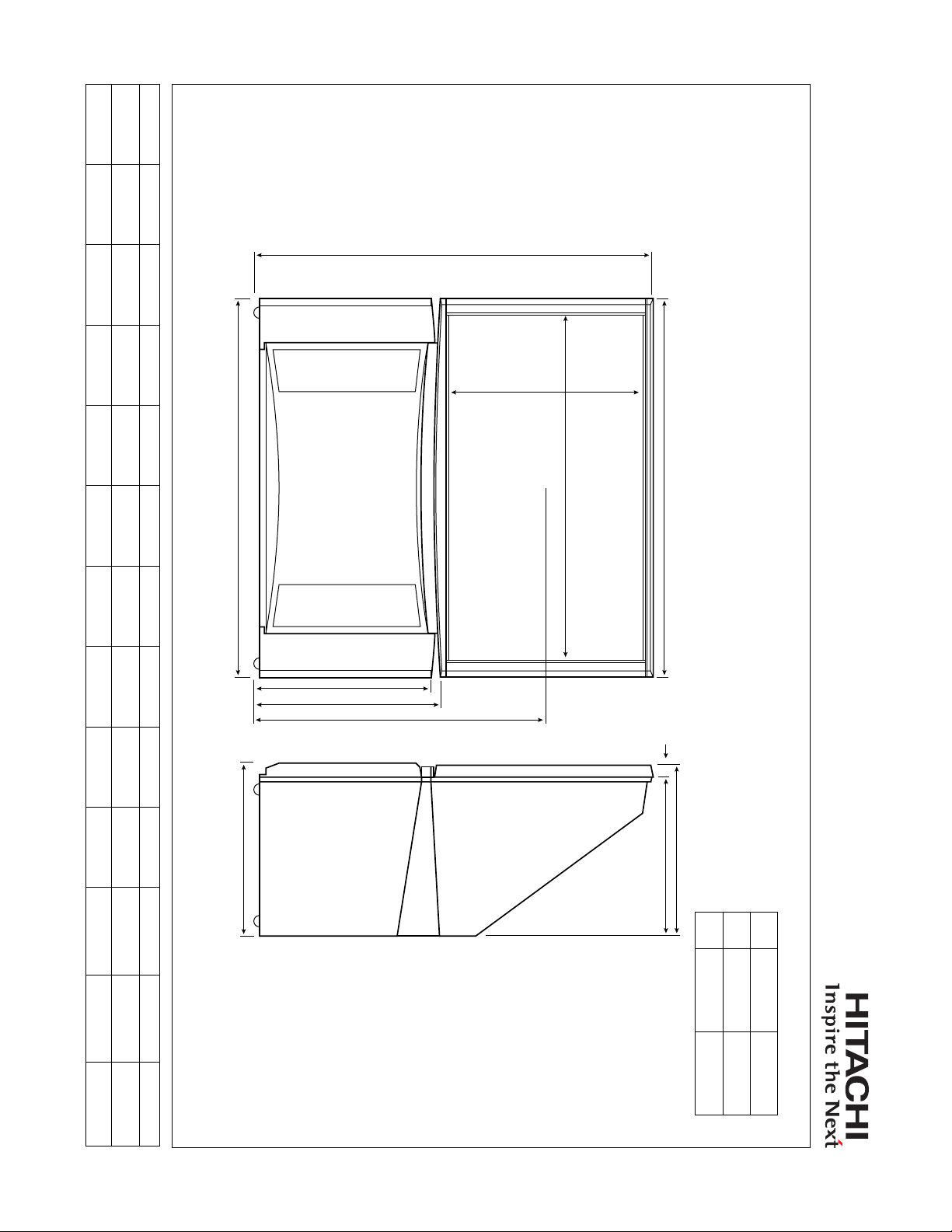
NOTE: All measurements are shown to the nearest 1/16th inch. This illustration is not necessarily drawn to scale and is intended for estimating space required for custom installations. Final measurements should be taken from the actual product
Page 01-02
before attempting installation. All dimensions are approximate measurements and subject to change without notice. Allow adequate space behind the unit for proper ventilation and cooling. Hitachi is not responsible for any typographical errors.
mm 1303 1239 579 608 955.5 635 1129 550 40
Inches
51F59 51" HDTV
Product Dimensions
48-13/16
1239
A
B
51-5/16
B
48-13/16 22-13/16 23-15/16 37-5/8 25 44-1/2 21-11/16
C D E F G H I
G
H
1-5/8
C
D E F
L
A
J
K
I
Quick specs
J
I
B
A
510
557
20-1/8
K
21-15/16
L
Depth
Width
48-13/16”
21-11/16”
Height
51-5/16”
Page 9

57F59
Page 01-03
DIGITAL
57" Digital Projection Television
Key Features
• 1080i Display
• DTV Tuner
1
2
• High-Brightness CRTs
• High-Brightness 4-Element
Lens System
• Magic Focus Auto Digital
Convergence
• 1080i Digital Video Processor
- 3 HD Aspect Modes
- 6 SD Aspect Modes
- 1080i/720p/480p/480i
Input Compatible
- Split Screen/Picture in Picture
• High-Contrast Fine-Pitch Screen
• 3-Color Temperatures
• Edge Enhancement (SVM)
• Black Enhancement
• Digital 3D Y/C Comb Filter
• Energy Star Compliant
Audio Performance Features
• MTS Stereo/SAP with dbx
™
• Simulated Surround Sound
• Full Range Speaker System
3
Convenience Features
• Day and Night Memory by Input
with Timer
• Front Panel Menu Controls
• Universal Remote Control
• 3-Language On-Screen Display
• Parental Locks (V-Chip)
• Closed Caption Decoder
• Sleep Timer
• Discrete IR Codes
• 2 Piece Cabinet
Specifications
• Color: ................................Gray/Black
Inputs/Outputs
• HDMI™ High-Definition
Multimedia Interface:
• Wideband Component
Video Inputs: ....................................
• S-Video Inputs (Rear/Front): .........
• AV Inputs (Rear/Front): .................
• Antenna Inputs: ................................
• Center Channel Input: ...........
• Fixed/Variable Audio Output: ..........
4
.....................1
L/Mono
Dimensions
• Height ......................................54 9/16"
• Width .............................................54"
• Depth ........................................ 23 5/8"
• Weight ...................................162 lbs.
Warranty
• 1 Year Parts and Labor Warranty
In-Home Service
• 2 Year Tube Warranty
1
Due to variances in program productions
and transmissions not all of the 1080 signal is
displayed.
2
Not QAM Compatible, 480i Output
3
Requires the internal tuner plus an external
tuner or other source device
4
HDMI input is compatible with DVI-HDTV
(HDCP) signals when combined with an
adapter cable. Adapter cable is not included.
All specifications and dimensions are
2
subject to change without notice. Refer to www.
hitachi.us/tv for updated custom installation
2/1
specifications.
4/1
© 2006 Hitachi Ltd. All trademarks are the
1
property of their respective owners.
1
Hitachi America, Ltd., Home Electronics Division 900 Hitachi Way, San Diego, California 91914 - www.hitachi.us/tv or 1-800-HITACHI
Page 10

NOTE: All measurements are shown to the nearest 1/16th inch. This illustration is not necessarily drawn to scale and is intended for estimating space required for custom installations. Final measurements should be taken from the actual product
Page 01-04
before attempting installation. All dimensions are approximate measurements and subject to change without notice. Allow adequate space behind the unit for proper ventilation and cooling. Hitachi is not responsible for any typographical errors.
mm 1378 1372 578 607 992 710 1262 592.3 40
1372
Inches
54-1/16 54-1/4 54-1/16 22-3/4 23-15/16 39-1/16 28 49-11/16 23-5/16 1-5/8
A B C D E F G H I J
B
G
H
57F59 57" HDTV
Product Dimensions
C
D E F
L
A
J
K
I
Quick specs
B
A
I
552.2
599.2
21-3/4
K
23-5/8
L
Depth
Width
54-1/16”
23-5/8”
Height
54-1/4”
Page 11

65F59
Page 01-05
DIGITAL
65" Digital Projection Television
Key Features
• 1080i Display
• DTV Tuner
1
2
• High-Brightness CRTs
• High-Brightness 4-Element
Lens System
• Magic Focus Auto Digital
Convergence
• 1080i Digital Video Processor
- 3 HD Aspect Modes
- 6 SD Aspect Modes
- 1080i/720p/480p/480i
Input Compatible
- Split Screen/Picture in Picture
• High-Contrast Fine-Pitch Screen
• 3-Color Temperatures
• Edge Enhancement (SVM)
• Black Enhancement
• Digital 3D Y/C Comb Filter
• Energy Star Compliant
Audio Performance Features
• MTS Stereo/SAP with dbx
™
• Simulated Surround Sound
• Full Range Speaker System
3
Convenience Features
• Day and Night Memory by Input
with Timer
• Front Panel Menu Controls
• Universal Remote Control
• 3-Language On-Screen Display
• Parental Locks (V-Chip)
• Closed Caption Decoder
• Sleep Timer
• Discrete IR Codes
• 2 Piece Cabinet
Specifications
• Color: ................................Gray/Black
Inputs/Outputs
• HDMI™ High-Definition
Multimedia Interface:
• Wideband Component
Video Inputs: ....................................
• S-Video Inputs (Rear/Front): .........
• AV Inputs (Rear/Front): .................
• Antenna Inputs: ................................
• Center Channel Input: ...........
• Fixed/Variable Audio Output: ..........
4
.....................1
L/Mono
Dimensions
• Height .....................................59 15/16"
• Width .............................................61"
• Depth ........................................ 25 3/8"
• Weight ...................................259 lbs.
Warranty
• 1 Year Parts and Labor Warranty
In-Home Service
• 2 Year Tube Warranty
1
Due to variances in program productions
and transmissions not all of the 1080 signal is
displayed.
2
Not QAM Compatible, 480i Output
3
Requires the internal tuner plus an external
tuner or other source device
4
HDMI input is compatible with DVI-HDTV
(HDCP) signals when combined with an
adapter cable. Adapter cable is not included.
All specifications and dimensions are
2
subject to change without notice. Refer to www.
hitachi.us/tv for updated custom installation
2/1
specifications.
4/1
© 2006 Hitachi Ltd. All trademarks are the
1
property of their respective owners.
1
Hitachi America, Ltd., Home Electronics Division 900 Hitachi Way, San Diego, California 91914 - www.hitachi.us/tv or 1-800-HITACHI
Page 12

NOTE: All measurements are shown to the nearest 1/16th inch. This illustration is not necessarily drawn to scale and is intended for estimating space required for custom installations. Final measurements should be taken from the actual product
Page 01-06
before attempting installation. All dimensions are approximate measurements and subject to change without notice. Allow adequate space behind the unit for proper ventilation and cooling. Hitachi is not responsible for any typographical errors.
mm 1521 1549 624 653 1087 808 1439 644 40
1549
Inches
61
A B
B
65F59 65" HDTV
Product Dimensions
59-7/8
61 24-5/8 25-3/4 42-13/16 31-13/16 56-11/16 25-3/8 1-5/8
C
G
D E F G H I J
C
D E F
L
H
A
J
K
I
23-13/16
604
33-9/16
851
Quick specs
B
C
L
Height
Width
Depth
K
33-9/16”
61”
59-7/8”
L
Page 13

POWER SUPPLY
INFORMATION
DP-6X CHASSIS
TRAINING PACKAGE
SECTION 02
Page 14

THIS PAGE INTENTIONALLY LEFT BLANK
Page 15
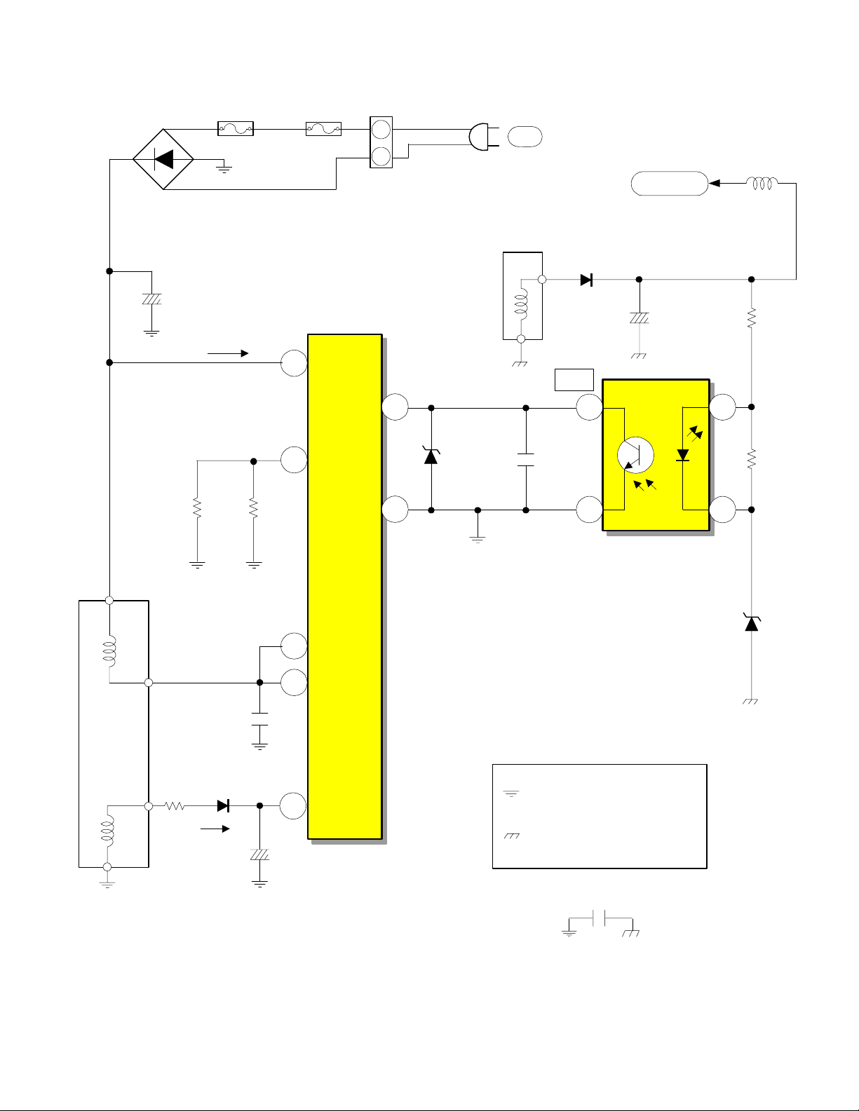
DP-6X CHASSIS POWER SUPPLY SBY 5.0V REGULATION CIRCUIT DIAGRAM
D901
1
3
2
+
C908
-
F902
1 Amp
4
Start Up
170V
0V
8 Amp
5
1
F901
Start Up
OCP
F/B
PA
2
1
4
1.08V
D907
AC
Secondary
T901
6
8
1.08V
C911
D949
FB
L930
SBY 5.0V
5.7V
C940
R957
I904
4
1
5.28V
R958
5
T901
Primary
1
2
R908
3
R906 D206
Run
R909
C909
C912
170V
16.3V
3
Gnd
I901
7
D
8
D
Hot Ground from pin 4 of
2
Vcc
Bridge Rectifier D901
Cold Ground from
pin 8 of T901
3
0V
Regulator
Photocoupler
MTZJ4.3B
C905
D962
2
4.30V
PAGE 02-01
Page 16
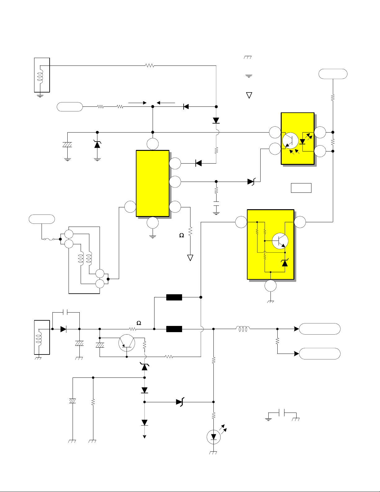
DP-6X CHASSIS POWER SUPPLY SW +115V REGULATION
T902
8
7.5P/P
9
1 of 3
Supplied from Relay S903
C914
AC Supplied from
Relay S903
Raw B+ from D902 Pin 1
150V
F903
AC
T902
1
2
5A
D910
High Voltage Power Supply
R914R913
Start Up
17.91V
176V
1 2
R915
Run
Osc B+
4
VIn
OCP/BD
0.55V
7
I902
Driver/
Output
IC
DS
Gnd
3
6
R916
0.05
D911
0.74V
OCP/FB
0.0V
D913
D912
R920
R921
C925
B+ 115V
Cold Ground from
pin 16 of TP01
Floating Ground from
pin 8 of TP01
AC Hot Ground from
pin 8 of TP01
11.38V
7.13V
D914
I906
4
3
Regulator
Photocoupler
I941
1 2
FB
8.58V
SW +10.5V
1
2
9.62V
8.58V
R963
R964
T902
11
12
3 of 3
C961
D945
C966
C968
2 of 3
C967
5
6
Q941
R960
R951
0.39
D946
D951
R955
Protect
OVP
D952
E946
0.5K
E947
R952
3K
D948
R956
D950
Deflection
R959
L948
B+ 115V
3
0.81A
SW +115V
R986
SW +35V
0.01A
C906
PAGE 02-02
Page 17
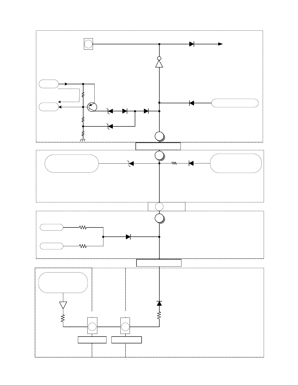
DP-6X PROTECT-OVP SHUTDOWN BLO CK DIAGRAM
PDS2
Power_1
6
If the 115V line experiences a high current demand, a
high is impressed on the anode of D946 or
If the 115V line goes too high, a high is impressed on
the cathode of D948, turning it on.
Source
+115V
115V Over
Current Det.
0.39
Q941
Load
+115V
ohm
D951D946
D948
115V Too High Det.
From DH13, CH17
off Pin 7 of Flyback
Excessive
High Voltage Det.
If the Heater pin line goes too high, a high is
impressed on the cathode of DH15, turning it on.
DH15
Q980 / Q981
7
Turns off Relay S903
Any high impressed on the base of Q980 will cause
the Relay to turn off. Q981 keep Q980 turned on as
D952
1
2
4
C
< Protect-OVP >
B
Vert. 26V Overcurrent Det.
If the Vert 26V line experiences a high current
demand, a high is impressed on the anode of D608
D944
Power_1
To Q944
Turns on Relay S903
long as the Power_1 high remains.
AC Too High Det.
From I905 / Q901
D959
If the AC line goes too high, a high is impressed on
D608R632
the anode of D959
Power-Def 1/1
From Q604
and Current Sensor
R609
Deflection 1/1
+ 5V
- 5V
RE35 Current
Sensor + 220V
Over Current Det.
QE08
RE34
RC47
- 5V Loss Detection
DC27
RC46
ERG1
7 3
AB
PCT
< VM Port > < CRT Prot >
7
PDT2
2
A
< Protect-OVP >
1
DX07
RY73
If the -5V line experiences
a short or disappears, a
high is impressed on the
anode of DC27
Signal 6/7 (Sweep Detection)
220V Overcurrent Detection
If the 220V line experiences
a high current demand, a
high is impressed on the
anode of DX 0 7
Red CRT
Green CRT
Signal 5/7 (RGB Processor)
PAGE 02-03
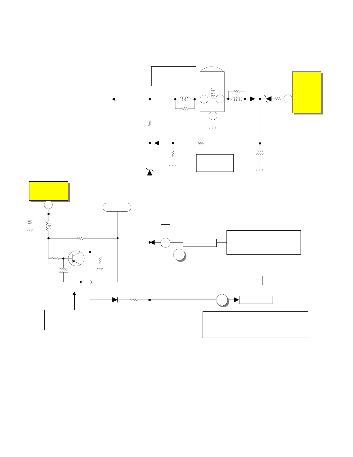
Page 18

DP-6X CRT and -5V LOSS PROTECT-OVP (A) SHUTDOWN DIAGRAM
RED CRT PWB
Def
+220V
CRT +220V Excessive
Current Detection
PDC1
1
CE10
+ 5V
- 5V
RE35
2.2 Ohm
QE08
RE29
RC47
RC46
To CRT 220V
To VM Circuit
RE30
RE34
VM PORT
RE31
-5V Loss Detection
DC27
-5V Loss Det.
CRT PWB
ERG1
A B
7
VM PORT
GREEN
PCT
3
CRT PROT
Signal 6/7
1
DX07
RGB Processor
Signal 6/7
RY73
< Prot-OVP >
1
< Prot-OVP >
1
SEE DEFLECTION SIDE (B)
PROTECT-OVP
SHUTDOWN DIAGRAM
PDT2
8
Active
Normal
2
A
< Prot-OVP >
PAGE 02-04
Page 19
DP-6X DEFLECTION SIDE (B) PROTECT-OVP SHUTDOWN DIAGRAM
Deflection Schematic
RH32 allows ABL fluctuations to
manipulate the Trigger Po int of Shut
Down as screen brightness varies. ABL
is inverse proportionate to brightness.
This prevents false triggering.
Vertical Output Circuit
I601
Vs
10
L603
C604
Q604
R630
C610
ABL
Def +28V
R629 0.68 Ohm
R631
ABL Voltage
Too High Det.
LH01
RH21
RH32
RH24
DH15
1
PDT2
2
8
A
Flyback
TH01
8
1
RH25
Excessive Hi
Voltage Det.
< Prot-OVP >
Hi Volt
77
H. Drive
IH01
OVP
High Voltage
Sensing Circuit
RH23
LH06
5OP
29.01V
Any fluctuations in High Voltage will
also be reflected by the 50P output P/P.
By monitoring the 50P (50 Pulse) rises
in High Voltage will be sensed. If High
Voltage climbs too high, DH15 will fire
and trigger a shut down event.
FROM CRT and -5V LOSS
SHUTDOWN DIAGRAM
DH13
CH17
PROTECT-OVP (A)
Normal
RH26
DH14
Stops H. Drive
Active
D608
Excessive Vertical
Current Det.
If the Vertical Output IC has a problem,
R629 will sense the current rise. The
voltage drop will be reflected at the base
of Q604 turning it on and producing a
Shut Down high.
R632
4
B
1
SEE 115V TOO HIGH AND OVER
CURRENT DETECTION (B~C)
PROTECT-OVP DIAGRAM
< Prot-OVP >
PAGE 02-05
Page 20
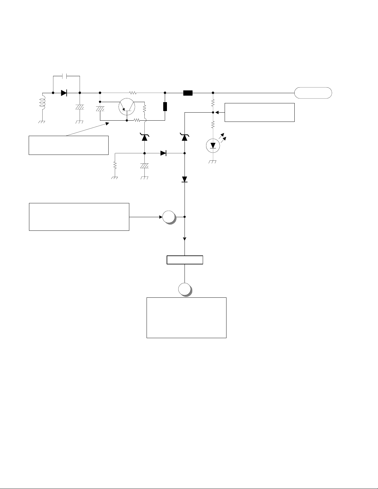
DP-6X 115V TOO HIGH AND OVER CURRENT DETECTION (B~C) DIAGRAM
Power-Def Schematic
CP45
EP46
500
3K
EP45
Deflection B+ 115V
Def +115V
RP54
Deflection B+ (115V)
Excessive Voltage Det.
RP55
DP59
TP01
DP46
17
CP51
16
Deflection B+ (115V)
Excessive Current Det.
CP59
QP41
RP47
0.39 Ohm
RP48
DP55
RP49
DP58
RP53
SEE DEFLECTION SIDE (B)
SHUTDOWN DIAGRAM
CP63
DP56
2
D926
4
B
< Prot-OVP >
C
6
SEE PROTECT-OVP (C)
SHUTDOWN CIRCUIT
PAGE 02-06
Page 21
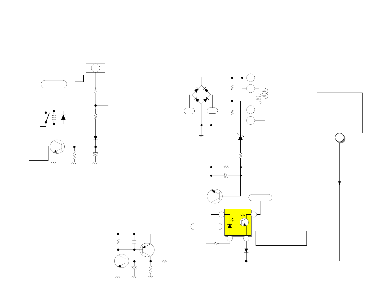
Power On/Off
From Sub Micro I002
Pin 62, Q012, Q013
Power_1
DP-6X PROTECT-OVP (C) SHUTDOWN CIRCUIT
Power-Def Schematic
For
Power
Supply
D902
Relay
Driver
SBY +5V
AC
Q944
S903
R942
D942
R945
D947
C942
6
onoff
R947
PDS2
AC
AC 175
Q901
Hot
Ground
On
Raw B+
D902
AC
R924
R925
D915
9V
R927
C916
(8.9V ~ 9.3V)
R926
I905
1
2
4
5
T902
SBY 5V
SEE
115V TOO HIGH
AND OVER
CURRENT
DETECTION (B~C)
DIAGRAM
c
6
2
Run B+ 16V
PAGE 02-07
R980
C980
Q980
C981
Q981
R982
R981
R923
7
1 3
D959
4
AC Voltage Too High
Detection
1
Page 22
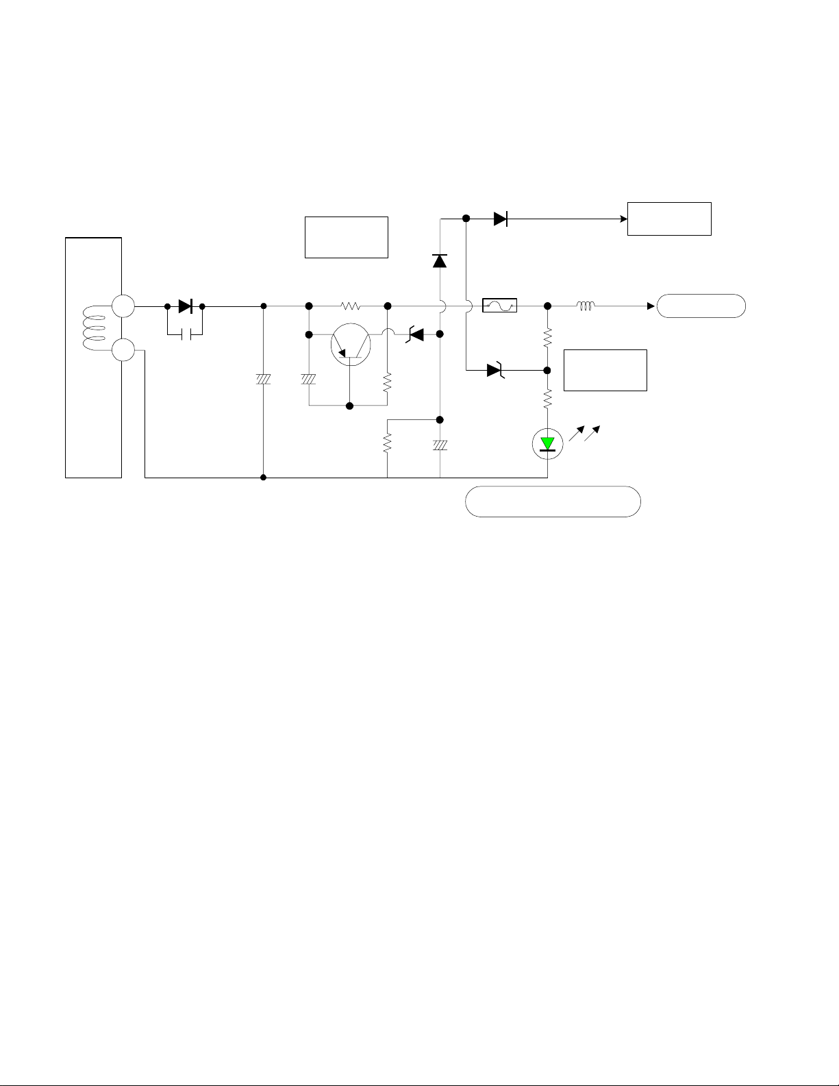
DP-6X CHASSIS
L.E.D. (Visual Troubleshooting) for the Deflection Power Supply
+115 Deflection B+ L.E.D. for visual troubleshooting observation.
See the Deflection Power Supply Shut
Down Circuit Diagram for details.
D952
T902
+115V
GND 1
11
12
D945
C961
+115V
C966
Q941
C967
+115V Over
Current
R951
0.39 Ohm
R960
D951
D946
R952
C966
E947
3 Amp
0.85A
R959
D948
R956
D950
SW +115V Active (LED)
L948
+115V Over
Voltage
GREEN L.E.D.
PROT_OVP
Active Hi
SW + 115V
PAGE 02-08
Page 23

DP-6X POWER ON and OFF CIRCUIT DIAGRAM
Power-Def 1/1
Raw B+ for
T902 / I902
I907
SW 5.6V
Regulator
3
Conv + 28V
D902
1
1
3
2
L931
C931
4
AC
1/2
SW+ 5.6V
R943
D944
For
Power Supply
AC
Q944
Relay
Driver
S901
D940
SBY +5V
S903
Power Supply
R945
D942
D947
onoff
R942
AC Route
when first applied
RUSH
For
C944
R947
From D954 off Main
Switching Transformer
R907
2.2
ohm
POWER 1
SW+ 10.5V
Pin 13
F902
1 Amp
F901
8 Amp
PDS2
6
on off
5
IA04
SW 9V
Regulator
Signal 4/7
Audio
AC
1/2
Signal 1/7 Main Micon
I002
Q012Q013
Microprocessor
61
Power On/Off 1
67
Power LED
PFT1
10
3
9
Power LED
Not Used
SW+ 9V
PFS
Ft Control
Sub
RH30
DM10
POWER
LED
2 1
on off
Q942
PAGE 02-09
C942
R940
Relay
Driver
S901 Turns On after the
SW 5.6V becomes
active. T h i s prevent s
surge current during
capacitor ch ar gi n g .
PA
AC
Page 24

THIS PAGE INTENTIONALLY LEFT BLANK
Page 25

VIDEO
INFORMATION
DP-6X CHASSIS
TRAINING PACKAGE
SECTION 03
Page 26

THIS PAGE INTENTIONALLY LEFT BLANK
Page 27

DP-6X CHASSIS VIDEO SIGNAL SELECTION PATH CIRCUIT DIAGRAM
Signal 3/7 AV Selector
Signal 2/7 Tuners
MTV-CVBS
U303 Main Tuner
Sheet 13
V5
S5
V4
V3
V2
S2
PAGE 03-01
V1
S1
Front Control PWB
Aux 5 Video V3V
Aux 5 S-Y V3Y
Aux 5 S-C V3C
S-5 Det.
Component 4 Y
Composite 4
Component 4 Pb/Cb
Component 4 Pr/Cr
Component 3 Y
Composite 3
Component 3 Pb/Cb
Component 3 Pr/Cr
Aux 2 Video
Aux 2 S-Y
Aux 2 S-C
Aux 1 Video
Aux 1 S-Y
Aux 1 S-C
4
1 2
PFT
2
7
9
S-2 Det.
S-1 Det.
NOT AVAILABLE
22
16
20
18
1711
61
26
59
57
67
24
65
63
10
14
12
11
4
6
8
5
I501
Video Select
CVBS2
MAIN OUT
V1
Y1
C1
S-1
CY2
SUB OUT
V8
PB2
PR2
CY1
V7
PB1
PR1
V3
Y3
Y5 DM In
C3
C5 DM In
S-3
V2
Y2
C2
S-2
MON OUT
Y
C Pb
C Pr
C Pr
C Pb
Y
CLK
DATA
G/CY1
R/PR1
B/BR1
36
32
33
34
30
29
28
45
44
11
13
73
69
71
For Micro. Sync detection
G/Y/CVBS
For Micro. Main CC detection
Main CY/Y/CVBS
Main_Pb
Main_Pr
Sub_Pr
Sub_Pb
Sub CY/Y/CVBS
For Micro. Sub
CC detection
See Sub Sync Signal Path
Y
30
True Y
61
True Pb
60
True Pr
SDL2
SDA2
DTV-CY
NTSC for Monito Out
DTV-C
23
See Main Sync Signal Path
100
PST
56
60
64
74
72
68
97
True 1080I
Rainforest IC
(Flex Bypass)
Signal 5/7 RGB Processor
FLEX CONVERTER
1
3
5
PR
QX09
66
PDTV1
19
15
16
17
18
Signal 2/7 Tuners
PB
QX10
67
IX01
Rainforest
U304
Digital
Tuner
HDV-Y
HDV-PR
HDV-PB
CY
QX11
68
Page 28

DP-6X Chassis A.B.L. Circuit Diagram
ABL
DX01
RX34RX33
CX17
QX12
RX35
CX18
RX36
RX37
Signal 5/7 PWB
SW +115V
ABL switches slightly reduce the
overall operational point of ABL due
to the loss of overall brightness levels.
RH42 47K
QH05
B_Side_Panel
RH43 180K
BLACK_
PANEL
PDT2
RH41
2
RH40
PDS2
RC95
ABL_SW
RH30
2
RH35
1080I
QH03
ABL Switch
RH33
2.2K
PAGE 03-02
ABL
3
As Brightness goes Up, ABL Voltage
goes Down. (Inverse Proportional)
SW +9.3V
DX02
CX20
SW +10.5V
Clamp
RX38
ABL
CX21
R091
R090
Deflection PWB
RH27 30K
To QH01 Collector
of High Voltage
Output Transistor
RH27 & RH28
ABL Pull-Up
Resistors
RH28 39K
[ Current Path ]
DH16
RD30EB4
RH31
CH18
75
78
6.8K
IX01
Rainforest
IC
SDA1
SCL1
B+
9
C
10
CH14
RH32
180K
RH24
43K
28
30
TH01
50P
CH21
FBT
LH06
7
RH23
1
Gnd
To Focus
ABL
8
LH01
RH21
RH25 13K
DH15
HZ22-2L
Signal 1/7 PWB
I001
Sub
Micro
Black Side Panel
59
ABL Switch
58
DH13
To
Anodes
Protect_OVP
H. Drive
DH14
RH09 CH10
CH17
Stops
IH01
OVP
7
RH26
Page 29

AUDIO
INFORMATION
DP-6X CHASSIS
TRAINING PACKAGE
SECTION 04
Page 30

THIS PAGE INTENTIONALLY LEFT BLANK
Page 31

DP-6X CHASSIS AUDIO SIGNAL SELECTION PATH CIRCUIT DIAGRAM
ANALOG TUNER U303
Signal 2 T uners
C515
C514
PFT2
C527
4
5
C526
C551
C552
C548
C549
C545
C546
C540
U303
Front Control PWB
Aux 5 Audio L
V5
V4
V3
V2
V1
Aux 5 Audio R
AVX 4 Audio L
AVX 4 Audio R
AVX 3 Audio L
AVX 3 Audio R
AVX 2 Audio L
AVX 2 Audio R
AVX 1 Audio L
AVX 1 Audio R
MTV-L
MTV-R
2
PAGE 04-01
C541
C576
C575
MONITOR
OUT
Monitor Audio Out L
Monitor Audio Out R
C574
C573
Signal 3 A V S e lector
83
L6
841
R6
81
L7
82
R7
91
L2
R2
92
MAIN OUT
89
L3
R3
90
I501
Audio Select
87
L4
88
R4
85
L5
86
R5
MON OUT
L Out 1
1
100
R Out 1
L8
R8
CLK
DATA
L1 Out
R1 Out
Hi-Fi
L1
R1
C512
80
C513
79
45
44
97
Selected Audio Out
96
SDL2
SDA2
QA06
QA07
C554
93
C553
94
DTV L
DTV R
CA15
CA12
CA15
CA12
CA29
CA27
CA28
CA26
CA30
CA25
QA04
QA05
Signal 2 T uners
1
7
3
I301
5
1
20
2
19
2
4
Signal 4/7 Audio
13
12
IA02
Audio
Control
L In
R In
IA03
Audio
Out
Digital
Tuner
U304
A Out R
A Out L
7
12
PR
CA41
1
PL
1
CA42
Page 32

THIS PAGE INTENTIONALLY LEFT BLANK
Page 33

DEFLECTION
INFORMATION
DP-6X CHASSIS
TRAINING PACKAGE
SECTION 05
Page 34

THIS PAGE INTENTIONALLY LEFT BLANK
Page 35

DP-6X SWEEP LOSS DETECTION CIRCUIT
Cut Off from Micro
during "Setup" to
prevent false
triggering of V
Sweep Loss during
RGB Cut Off
adjustment.
V. Blk.
14V P/P
Vertical Blanking
From Pin 11 I601
From
Deflection 1/1
Horizontal Blanking
From Q706 Emitter
8V P/P
H. Blk.
PDT2
7
10
4
RC21
RC22
CC08
SW +10.5V
CC09
Cut Off
QC06
RC24
CC10
RC28
From Pin 60 I002 Sub Microprocessor (Signal 1/7)
QC10
DC26
QC11
RC25
RC30
RC27
DC23
DC22
RC23
DC21
CC06
DC19
H Det
RC22
V Det
DC20
RC16
RC17
CC13
RC18
QC09
RC14
DC18
QC08
RC29
RC26
RC19
QC07
RC13
RC36
Signal 6/7
Sweep Detection
RC34
QC13
RC35
RC37 DC25
DC24
RC32
RC33
CC12
Protect
Switch
QC12
RC31
CC11
Def 6.3V
See Video Mute
Generation
Circuit
A
Protect HV
PAGE 05-01
Page 36

THIS PAGE INTENTIONALLY LEFT BLANK
Page 37

MUTE CIRCUIT
INFORMATION
DP-6X CHASSIS
TRAINING PACKAGE
SECTION 06
Page 38

THIS PAGE INTENTIONALLY LEFT BLANK
Page 39

DP-6X CHASSIS VIDEO MUTE GENERATION CIRCUIT DIAGRAM
RC58
DC29
PDS2
DC17
Hi
Mute
QC17
RC56
CONV. AMP
Signal 7/7
From
pin 1 IK03
Mutes Convergence
when +28V line drops.
Active Low
Active
Prot HV
3
D
Shuts off IH01
High Voltage
Driver IC
Hi
Signal 6/7
Sweep Detection
AC SIGNAL
From
Power-Def1/1
From Pin 3 I903
Signal 3/7
AV Selector
To Q504, Q505
through D512
Mutes Monitor Out
Audio
To IX01
Pin 39
Mutes Video
Signal 5/7
RGB
Processor
PCT
To
Mute
CRTs
11
PDS2
7
F
E
V_MUTE 2
B
V_MUTE 1
QC01
Def 6.3V
SW +9.3V
QC24
RC14
QC05
SW +9.3V
RC02
0 ohm
RC03
RC10
RC11
RC06
QC02
V_MUTE 1
DC16
DC14
RC07
RC05
RC09
CC04
DCU 2/2
Dig Conv.
IT01 pin 45
Prot_HV
From Sweep Loss
Detection Circuit
QC07 & QC12
RC08
AC Det
Normal O ff
CC02
DC15
QC23
Mute
CC03
QC04
AC Det
Prot HV
V Mute
1
PDCU
A
V Mute0
Active
RC57
CC29
Q024
PAGE 06-01
Signal 4/7
Mutes Audio
I002
C
72
Q025
Signal 1/7
Main Micon
V Mute
AC Det = Loss of AC
Prot HV = Loss of H or V Sweep
V Mute = Channel Change,
Power Off/On, Auto
Programming, etc..
Page 40

From Mute
Generation
Circuit Diagram
PDS2
3
D
Prot HV
DP-6X HI VOLTAGE MUTE CIRCUIT
Deflection 1/1
High Voltage
Driver IC
IH01
Stops
14
Drive
RH06
From Q706
H. Blk
DH12
RH16
DH04
DH02
RH07
Stops
3
Osc
1
H Drive
+ 115V
TH01
Flyback
9
10
Lo
Active
RH37
RH06
DH03
RH36
QH02
QH04
RH13
QH01
Horz Output
PAGE 06-02
Page 41

DP-6X CHASSIS AUDIO OUTPUT SELECTION MUTE CIRCUIT DIAGRAM
20
IA02
Audio
Control
1
V_MUTE
AUDIO
MUTE
I002
Micro
SP_MUTE
SP_OFF
SP_R
SP_L
72
Q024 Q025
73
Q018 Q019
74
19
2
Right Main Audio
Left Main Audio
DA11
DA12
DA13
DA14
CA28
CA27
RA47
RA40
RA39
QA08
RA57
RA49
QA09
RA49
CA50
CA30
CA29
CA49
QA10
RA50
RA46
RA45
4
2
11
6
CA48
QA03
IA03
Audio
Out
MUTE
Ripple
Filter
12
DA05
7
CA41
CA42
CA47
PR
R
L
1
PL
1
Signal 1/7
Main Micon
RA58
RA59
AU+29V
QA12
Signal 6/7
Sweep Detection
QA14
C
PAGE 06-03
V_MUTE 2
QA11
RA60
RA01
SW +9V
4
5 SW +10.5V
IA04
3
1
2
RA03
Signal 4/7 Audio
Page 42

DP-6X CHASSIS RAINFOREST IC MUTE CIRCUIT DIAGRAM
Signal 5/7
RGB Processor
IX01
RGB
Processor
(Rainforest IC)
QX06
RX12
DX03
RX64
RX09
QX05
RX08
SW+ 9.3V
Signal 6/7
Sweep Detection
PST
9
10
Signal 3/7
A/V Selector
FC V Blk
Flex
Converter
FC H Blk
H Blk
PDT2
4
Deflection 1/1
From Q706
Emitter
FBP In
R Out
PAGE 06-04
G Out
B Out
39
12
13
14
RX63
E
V_MUTE 1
Page 43

Signal 6/7
Sweep Detection
F
I501
Video /
Audio
Selector
DP-6X CHASSIS MONITOR AUDIO OUTPUT MUTE CIRCUIT DIAGRAM
C574
C573
R5C4R5C5
R3 Out
L3 Out
100
1
Right Audio
Left Audio
D512
C576
C575
R5E3
R5C7
R5C6
Q504
R5C9 R5C8
Q505
R5E2
MONITOR
OUT
Right Audio
Left Audio
V_MUTE 1
V_MUTE
72
Q024 Q025
D510
I002
Micro
Signal 1/7
Main Micon
PAGE 06-05
Signal 3/7
AV Selector
Page 44

THIS PAGE INTENTIONALLY LEFT BLANK
Page 45

DIGITAL
CONVERGENCE
INFORMATION
DP-6X CHASSIS
TRAINING PACKAGE
SECTION 07
Page 46

THIS PAGE INTENTIONALLY LEFT BLANK
Page 47

Magic Focus
IR Out
HMO1
IR Receiver
Ft. Control PWB
PAGE 07-01
SM09
1
Q028
DM07
QM04
QM01
DP-6X CHASSIS "DIGITAL CONVERGENCE" INTERCONNECTION CIRCUIT DIAGRAM
1
4
2
Main Micon
Signal 1/7
I007
3
6
1
5
8
7
PFS
Sby +5V
3
Q028
IR In
Main Micon
Signal 1/7
Sensor PWB
LED
S0 ~S7
8 Total
Sensors
I002
55
MAG SW In (Lo)
56
IR Out
57
DCU IR Sel
DCU Size
52
IR
6
53
Digicon Adj
Magic Sw Out
Digicon
Busy In
Microprocessor
SC01
Service
Only
From QC16
From IC01
PSET
+5V
Gnd
S7
S6
S5
S4
S3
S2
S1
S0
To Rainforest
OSD B
34
OSD G
33
OSD R
32
BUSY
51
54
10
9
8
7
6
5
4
3
2
1
-5V
+5V
Sweep Det
Signal 6/7
Sw Adj
AV Selector
Signal 3/7
DC_B
DC_G
DC_R
DC _YS
31
23
27
19
25
29
17
21
15
44
40
16
18
20
22
24
26
28
30
PDCU
Flex
CY
PB
PR
DC_YS
DC_R
DC_G
DC_B
DC_Busy
Magic SW 2
DC Adj 2
DC_IR 2
SW_ADJ
54 90 125
V Blk 2
H Blk 2
DC_Size
S7
S6
S5
S4
S3
S2
S1
S0
DCU 1/2
PST
1
3
5
53
50
49
48
66
60
61
25
59
IS04
3.3V Reg
18547
35
33
27
65
3 12
75
76
77
78
79
80
1
2
IS06
IS07
IS06
IS07
Rainforest
QX11
QX10
QX16
Includes OSD
QX09
QX23
QX22
QX21
66
Y1 In
67
Pb1 In
68
Pr1 In
26
Dig OSD B
25
Dig OSD G
24
Dig OSD R
2 YS3
IX01
OSD
20
19
18
14
13
12
PDCU
Conv+28
14
RV
IT07
7
1
RH
4
2
-5V
3
+5V
GH
GV
BV
BH
Mute
DC29
6
8
12
10
Mute
"Lo"
1
IT06
7
7
IT05
1
IT01
45
7
RES
1
DT01
DCU 2/2
IK03
2
Mute
Mute
RK37
11
RGB PROCESSOR
Signal 5/7
OSD B
OSD G
OSD R
B
G
R
13
IK01
6
RV
+
12
18
RH
3
+
7
GH
19
+
5
Conv-24
5
9
13
IK02
6
GV
12
+
7
3
BV
+
19 20
18
BH
+
RK38
RK40
DK27
-
-
-
-
-
-
QX19
QX18
QX17
QX36
QX32
QX28
15
14
17
11
10
8
23
22
20
9
11
10
8
23
22
15
14
17
Conv+28V
Conv Amp
Signal 7/7
From
Micro
CYV+
CYVCYH+
CYH-
CYH+
CYH-
CYV-
CYV+
CYV+
CYV-
CYH+
CYH-
PCT
9
7
5
PCR
1
3
6
4
PCG
6
4
3
1
PCB
1
3
4
6
To CRTs
B
G
R
To Red Convergence Yokes
To Green Convergence Yokes To Blue Convergence Yokes
Page 48

DP-6X CLU-4361S REMOTE SHOWING DCAM FUNCTIONS
CLU-4361S p/n HL02291
When Convergence is adjusted by this Remote, this Remote must be changed to DCAM mode.
Remote begins in TV mode.
While holding the "TV" key down, press and release "MENU" then press and release "INFO" then
release the "TV" key.
CLU-4361S
Returning the Remote to Normal Mode
Remote begins in DCAM mode.
While holding the "TV" key, press the "0" then the "1" keys.
Be sure to return the Remote Control to
Normal Mode after DCAM.
PAGE 07-02
Page 49

CHASSIS
PICTURES
DP-6X CHASSIS
TRAINING PACKAGE
SECTION 06
Page 50

THIS PAGE INTENTIONALLY LEFT BLANK
Page 51

DP-6X PWB PICTURES
SIGNAL PWB
PAGE 08-1
Page 52

DP-6X PWB PICTURES
DEFLECTION PWB
PAGE 08-2
Page 53

DP-6X PWB PICTURES
DIGITAL PWB
DCU PWB
CONTROL PWB
PAGE 08-3
Page 54

DP-6X PWB PICTURES
CRT PWB
PAGE 08-4
Page 55

KEY
PARTS
DP-6X CHASSIS
TRAINING PACKAGE
SECTION 08
Page 56

THIS PAGE INTENTIONALLY LEFT BLANK
Page 57

DP-65 KEY PARTS IDENTIFIED
51F59 PWB PART NUMBERS 51F59 OTHER ADDITIONAL KEY PARTS
P/N DESCRIPTION P/N DESCRIPTION
UE25921 DP65 CHASSIS ASSY HL02291 CLU-4361S REMOTE CONTROL
UE25941 DP6X SIGNAL BLOCK ASSY KS21431 51 DP6X 2ND MIRROR
UE25951 DP65 POWER DEFLECTION BLOCK ASSY QD53401 51F59 SPEAKER GRILLE
JT25591 DP6X CPT/CONT PWB ASSY UX26071 DP65-51 SVC PRT ASSY (R)
JT25601 DP6X SENSOR PWB ASSY UX26072 DP65 51 PRT ASSY (G)
JT25581 POWER DEFLECTION PWB UX26073 DP65 51 PRT ASSY (B)
JT25561 DIGITAL PWB ASSEMBLY UX26081 DP65 SCREEN ASSY 51
JT25551 SIGNAL PWB ASSEMBLY UX26091 51F59 SVC FRAME ASSY
57F59 PWB PART NUMBERS 57F59 OTHER ADDITIONAL KEY PARTS
P/N DESCRIPTION P/N DESCRIPTION
UE25921 DP65 CHASSIS ASSY HL02291 CLU-4361S REMOTE CONTROL
UE25941 DP6X SIGNAL BLOCK ASSY KS09403 57 DP6X MIRROR
UE25951 DP65 POWER DEFLECTION BLOCK ASSY PH33954 57F59 SPEAKER GRILLE
JT25591 DP6X CPT/CONT PWB ASSY UX26074 DP65-57 SVC PRT ASSY (R)
JT25601 DP6X SENSOR PWB ASSY UX26075 DP65 57 PRT ASSY (G)
JT25581 POWER DEFLECTION PWB UX26076 DP65 57 PRT ASSY (B)
JT25561 DIGITAL PWB ASSEMBLY UX26082 DP65 SCREEN ASSY
JT25551 SIGNAL PWB ASSEMBLY UX26092 SCREEN FRAME ASSY
65F59 PWB PART NUMBERS 65F59 OTHER ADDITIONAL KEY PARTS
P/N DESCRIPTION P/N DESCRIPTION
UE25921 DP65 CHASSIS ASSY HL02291 CLU-4361S REMOTE CONTROL
UE25941 DP6X SIGNAL BLOCK ASSY KS07997 65 DP6X MIRROR
UE25951 DP65 POWER DEFLECTION BLOCK ASSY PH34152 57F59 SPEAKER GRILLE
JT25591 DP6X CPT/CONT PWB ASSY UX26071 DP65 65 SVC PRT ASSY (R)
JT25601 DP6X SENSOR PWB ASSY UX26072 DP65 65 PRT ASSY (G)
JT25581 POWER DEFLECTION PWB UX26073 DP65 65 PRT ASSY (B)
JT25561 DIGITAL PWB ASSEMBLY UX26083 DP65 SCREEN ASSY
JT25551 SIGNAL PWB ASSEMBLY UX26093 SCREEN FRAME ASSY
PAGE 09-01
Page 58

THIS PAGE INTENTIONALLY LEFT BLANK
Page 59

THINGS YOU
SHOULD KNOW
DP-6X CHASSIS
TRAINING PACKAGE
SECTION 10
Page 60

THIS PAGE INTENTIONALLY LEFT BLANK
Page 61

August 2006 (ver 01)
TOPICS PAGE
DP-6X Things You Should Know Index
Materials prepared by
Alvie Rodgers C.E.T.
SECTION (10) THINGS YOU SHOULD KNOW:
The Number on the Left of the Topic is the same number as shown on the Things You Should
Know page on the Web Site.
• (01) ATSC Reception problems ------------------------------------------------ ------------------ 10-01
• (02) Lead Free Solder beginning in 2004 ------------------------------------------------------ 10-02
• (03) Fan Part # GS00821: In Digital Module ---------------------------------------------------- 10-02
• (04) CRT- I need to Change All Three CRTs, what to do? -------------------------- ----- 10-03
• (05) How to do a Software Upgrade on the ATSC Digital Module ---------------------- 10-04
• (06) How to Troubleshoot Digital Convergence Problems ------------------- ------------ 10-08
• (07) Serial Number is shown on a Label on the Front Right Hand Side --------------- 10-10
• (08) HDMI Shows Error Message on HD Channels from Cable Box ------------------- 10-10
• (09) Using Cut Off Adjustment to Check for Defective CRT --------------------------- 10-11
• (10) Picture Dark or Abnormal, Changing Color Temperature -------------------------- 10-11
• (11) POD (CableCard) Problems -------------------------- --------------------------------------- 10-11
• (12) Lip Sync Issues --------------------------------------------------------------------------------- 10-12
• (13) HD Generator Suggestions ---------------------------------------------------- -------------- 10-13
• (14) Some VGA to Component Adaptors cause Picture Problems -------------------- 10-13
• (15) POD (CableCARD) no longer works after Initialization ------------------------------- 10-13
• (16) POD (CableCARD) Digital Tuner Problem --------------------------------------------- 10-13
• (17) What is the Size of the Allen Wrench for Splitting the Cabinet ---------------- 10-13
• (18) HDMI Doesn’t Work ------------------------- -------------------------------------------------- 10-13
• (19) Downloading the Latest Software ------------------------------------------------------- 10-14
• (20) Losing Most Channels on the PinP Window (With CableCARD) -------------- 10-14
• (21) Preventing CRT Phosphor Spots --------------- ----------------------------------------- 10-15
• (22) Horizontal Line Noise in Top Corners Prevention ---------------------------------- 10-16
Table of Contents Page 1 of 2
Page 62

This Page Intentionally Left Blank
Page 63

DP-6X THINGS YOUR SHOULD KNOW
(01) ATSC Reception problems:
Important information to gather when encountering a customer with ATSC reception problems. Please
gather all information listed below before calling for Technical Assistance.
(See below for contact information).
1. Make sure we are dealing with ATSC reception issues only, please.
2. Model and serial number...By the way, we are placing ALL model and serial
numbers on the front right hand side of the units.
3. Did the customer run auto programming? Please run auto programming again just in case.
4. Signal strength on this channel? Available through customer menu.
5. What kind of antenna are they using? Rabbit Ears? Roof antenna? Are they using antenna rotor? Cable?
6. What is the Software version? This is available through the customer menu.
7. What channel is having the problem? Digital channels are a main channel and a sub channel, always
displayed as : 25-1 or 25-2 and 25-3, 25-4, etc,.
Please ask for all sub channels available, sometimes there are more than one or two.
8. Do they know it's respective channel on analog format (NTSC)? Is the analog channel coming in ok?
Just to give you an example:
San Diego channel 8 NTSC is equal to channel 25-1 ATSC, when you do auto programming, you will
see 8-1 on TV OSD, but you can also enter: 25-1 and you will also get to the same 8-1 digital channel.
We all must be very familiar with this fact in order to see if we can select the channel directly, without
the need to do auto programming. See www.transmitter.com for state by state listing of analog/digital
equivalency table, their location and their power.
9. What is the stream reception format? You will see: 480i, 480p, 720p or 1080i on the upper section of the
OSD when receiving.
10. What is the Channel content? Is this ABC, CBS, PBS? And station identification is needed, like WYCN
TV Channel 5 or whatever.
11. Try to contacted the Local Station? Explain the problem to the engineer. They may be able to investigate
and make some corrections. If you did speak to someone at the station, whom did you talk to? Name and
phone number or e-mail address?
12. Local stations are starting to provide a feedback for their customers mostly through a web page....They
always want to know if customer are receiving the Digital Channels and are always looking forward to
get feedback.
13. Try PIP and make sure the PIP channel is also the same channel as the one they are trying to receive
with Ant C.
14. Describe problem and if possible, send a picture/drawing or a video.
15. Is sound OK?
16. Customer name and phone numbers, please.
Once this information is gathered, please contact Hitachi Technical support (see below) and provide all
information gathered.
Phone: 800-393-2369 (Authorized Servicers only)
Phone: 619-591-5352 (Non-Authorized Servicers only)
FAX: 619-482-8045
EMAIL: techsupport@hhea.hitachi.com
(Continued on page 2)
PAGE 10-01
Page 64

DP-6X THINGS YOUR SHOULD KNOW
(02) Lead Free Solder beginning in 2004.
2004 product will use lead free solder (unleaded) to help preserve the environment. Please read these instructions
before attempting any soldering work.
Caution: Always wear safety glasses to prevent fumes or molten solder from getting into the eyes. Lead free
solder can splatter at high temperatures (140
Lead free solder indicator
Printed circuit boards using lead free solder are engraved with an "F".
Properties of lead free solder
The melting point of lead free solder is 104 ~ 122
Servicing solder
Solder with an alloy composition of Sn-3.0Ag-0.5Cu or Sn-0.7Cu is recommended.
Although servicing with leaded solder is possible, there are a few precautions that have to be taken. (Not taking
these precautions may cause the solder to not harden properly, and lead to consequent malfunctions.)
Precautions when using leaded solder
Remove all lead free solder from soldered joints when replacing components.
If leaded solder should be added to existing lead free joints, mix in the leaded solder thoroughly after the lead
free solder has been completely melted (do not apply the soldering iron without solder).
Servicing soldering iron
A soldering iron with a temperature setting capability (temperature control function) is recommended.
The melting point of lead free solder is higher than leaded solder. Use a soldering iron that maintains a high
stable temperature (large heat capacity), and that allows temperature adjustment according to the part being
serviced, to avoid poor servicing performance.
Recommended soldering iron:
Soldering iron with temperature control function (temperature range: 320-450
Recommended temperature range per part:
degrees
F) .
degrees
F. higher than leaded solder.
degrees
F .
Part Soldering iron temperature
Mounting (chips) on mounted PCB 608 +/- 86
Mounting (chips) on empty PCB
Chassis, metallic shield, etc.
716 +/- 86
788 +/- 86
degrees
degrees
degrees
F
F
F
(03) Fan Part # GS00821: In Digital Module
• The Fan Runs all the time
• All sets with a Digital Module (ATSC Tuner) has a Fan
. This is normal.
.
• The below chassis utilizes a Digital Module which contains many sophisticated circuits.
A cooling fan is utilized in all Digital Modules (ATSC). It is normal for the customer to hear air
circulating and the fan running if the room is quiet. This can be compared to a computer
cooling fan as they are very similar. The customer may not be aware of the fact that his or her projection
television has a cooling fan incorporated. Please educate the customer with this
information. Do not assume that just because the customer can hear the fan that there is a problem with
the fan. Only if the fan produces a grinding or ticking sound should it be
considered to be defective.
• These Fans are running ALL the time. This is NORMAL operation. These applies to ALL Hitachi units
with an integrated ATSC tuner.
This is, is getting to be a very important issue for all our customers. Remember, one huge difference
•
between their previous TV sets and any of these NEW Digital Models is the fact that their previous TVs
never had a fan...therefore, there was no fan noise at all!
• Now, once they notice the fan noise, some of them do not like it. First thing they do is: They call for service.
Many Technicians MAY NOT be familiar with these units, therefore, they can not tell if the noise is actually
normal or too noisy!
(Continued on page 3)
PAGE 10-02
Page 65

DP-6X THINGS YOUR SHOULD KNOW
• Replacing the fan just to see if the noise goes away or to reduce it is just too much work and it will be for
nothing....then the Customers will be disappointed to find out the noise is still there (after any of the fans/
modules/or even complete TV sets were replaced). But once they hear the explanation related to the REASON why they hear this noise, they always understand.
• New Technology requires the use of faster processors, these processors require the use of cooling fans. Although minimal, these fans do make noise when they are running, this is "normal" operation noise.
(04) CRT- I need to Change All Three CRTs, what to do?
In a situation where it becomes necessary to replace all three CRTs, it may not be as big a job as first considered.
There are many times in which if a couple of First steps are followed, the job may be very easy thanks to Magic
Focus.
IMPORTANT: You must find the reason for the CRT burn ( if this is the reason for replacing all three CRTs at
once), before installing the new CRTs. Look for Deflection collapse caused by poor solder connections on the
Yoke Plugs, Convergence Yoke Plugs, Vertical Output IC, Drive Transformer and/or Flyback. Make sure the H
and V Sweep Loss circuit is functioning. Make sure the Yoke plugs are seated properly. Clean all Spark Gaps.
Pry off the caps on top of each spark gap and clean the contacts with a thin, fine sand paper. Reinstall the caps.
Solder all interconnections between the Signal PWB and the Deflection PWB.
THINGS TO REMEMBER:
• If at least one of the defectives CRTs is properly set up (in relationship to geometry) then it can be used as a
guide for setting up the new CRTs. This means you have checked that the Center is in dead center and that
the lines running left to right and top to bottom are straight and all the grids are linear.
• Magic Focus will be your biggest friend in the process.
• If at all possible, do not remove all three defective CRTs at once. Leave the best adjusted CRT in place until
the other two new ones have been installed and aligned.
• You most likely will not need an Overlay unless the set is already a mess related to geometry.
HERE IS THE PROCESS:
• After receiving the new CRTs, first determine which of the defective CRTs is best aligned. (This doesn't
matter which color). For our discussion we will say it's the Red.
• Remove the Defective Green CRT.
• Install the New Green CRT.
• Clear the RAM. (With Power Off, press and hold the Service Only switch. The press the Power Button on
the Front Panel). Set will come on with cleared RAM. No Convergence Correction.
• Loosen the Yoke on the New Green CRT and rotate it until it matches the Defective Red Vertically and
Horizontally (TILT) while looking only at the center. Don't worry if the Center isn't aligned with the Red.
After adjusting the Tilt, tighten the Yoke.
• Run a string from the top left corner to the bottom right corner.
• Run a string from the top right corner to the bottom left corner.
(This will give you a center mark where the strings cross.)
• Now, using the centering magnet for Green, adjust Green to the center mark where the two strings cross.
Remember that the RAM has been cleared. In this condition the Red is to the Left of Dead Center and the
Blue is to the Right of Dead Center. This is normal.
• Now, Power Off the set. Then turn it back on. This will restore the previous Convergence stored data. If you
checked the Red centering before all of this began, (Item 1 under Things To Remember above), then the new
Green CRT and defective Red CRT centers should now match.
• Run Magic Focus. This should now return the set to proper Convergence or at least very close where only a
minor touch up should be required. You can do this touch up now or wait and do it after all three CRTs has
been replaced.
Now, do the same thing with the New Blue CRT starting with step (2) above.
PAGE 10-03
Page 66

DP-6X DIGITAL MODULE SOFTWARE UPGRADE PROCEDURE
How to do a Software Upgrade on the ATSC Digital Module. Check web site for current version.
Preliminary Procedure: Note: MMC = Multi-Media Card (Page 1 of 3) Gain access the rear of the TV.
Insert the MMC (Figures 1 and 2) into the Multi Media Card slot as shown in Figures 3 - 6. Push the MMC
in until you hear a click, indicating the MMC is properly inserted.
Top View - MMC (Figure 1)
Rear View - TV Jack Panel (Figure 3)
Bottom View - MMC (Figure 2)
Example of
Software Version
Note:
Software Version
number will vary in
accordance to the
Version Released.
Your Version may
be different than the
one shown.
Close Up View of the MMC Slot
(Figure 4)
MMC goes in this direction
(Figure 5)
MMC Fully Inserted (Figure 6)
Continued on Next Page
PAGE 10-04
Page 67

DP-6X DIGITAL MODULE SOFTWARE UPGRADE PROCEDURE
Upgrade Procedure:
Step (1) Insert MMC Card fully into slot until it clicks.
Step (2) Turn the TV ON.
Step (3) Press the MENU button on the Remote.
Step (4) Menu will appear
Step (6) The Setup Menu will appear.
Step (5) Thumbstick Down and Highlight
SETUP and press SELECT.
Step (7) Continue to Cursor down and highlight
Upgrades and press Select.
Step (8) If the MMC card isn't already inserted, insert MMC card fully until it Clicks.
Step (9) Cursor Down and Highlight Upgrade Now and press Select.
Continued on Next Page
Continued on Next Page
PAGE 10-05
Page 68

DP-6X DIGITAL MODULE SOFTWARE UPGRADE PROCEDURE
Step (10) The Upgrade begins. Upgrade will take
approximately 2 ~ 3 minutes.
Step (11) After the Software Upgrade is
Complete,
*If your product has already been
upgraded or is the same version as the
one on the MMC, this step will be
bypassed.
Note: The old Software Version will
still appear on the screen. The updated
software version will not appear until
the TV is Reset. See the Next Step.
Step (12) After Software upgrade/s have been successfully completed, please turn the power off.
Remove the MMC Software Upgrade Card from the rear of the TV.
Then unplug the AC power cord for 60 seconds to reset the TV.
Plug in the AC power cord.
Repeat steps 2 through 8 to check the software version for verification.
Step (13)
Your software version should now show
correct version number as shown on the
MM Card front Label.
Note: To remove the MMC, gain access to the rear of the set. Push the card in until a click is heard,
this will release the MMC and then remove the card.
NOTE: The MMC must be removed and returned to Hitachi in order to receive any future upgrades.
Continued on Next Page
PAGE 10-06
Page 69

DP-6X DIGITAL MODULE SOFTWARE UPGRADE PROCEDURE
IMPORTANT NOTE:
Are you aware that HDTV/SDTV Channels that are shown On Screen may not be the actual channel numbers
that you would press on the TV remote control to tune that specific channel?
In other words, what you see on the PTV Screen is called VIRTUAL CHANNEL. As and example, to receive
(8-1) in San Diego (with out running auto programming in a DTV ) you will actually need to tune to channel 55.
Because UHF channel 55 is were they are receiving the Digital Virtual channel 8-1. The Virtual Channel information is embedded within the data received is the Virtual Channel ID. This was decided because the Customer
will know that the HDTV channel they are watching will be a known channel in their area. This will help them to
recognize the channel of origin.
Below is an excellent web site to visit. This can be a tool that will help you KNOW what the actual channel is
when you are going to randomly select them by remote control number keys. You can just select it without a
need to run auto programming (on most units ~ with exception of the WXW prior to software upgrade).
http://www.transmitter.com DTV Channel Allocation for the whole USA…
SOFTWARE UPGRADE PROCEDURE
QUICK STEPS.
1. Insert the MM Card software upgrade card into the MM Card slot in the read of the set. Be sure to
push in until a click is heard. Note. Label on the card is to the left.
2. Turn the Set On.
3. Press Menu
4. Thumbstick down to the 2nd page of the Setup Menu and Select Upgrades
5. Thumbstick down and Select Upgrade Now
6. After completion, Power off the set, Remove the MM Card, wait 60 seconds.
7. To verify the upgrade took place, repeat steps 2 through 4 and check the version.
NEW: The Software can be downloaded from our web site. www.hitachiserviceusa.com
(User Name and Password required). Go to the Training section and click on “Software Version and
Download Page” link.
and Select Setup.
.
.
PAGE 10-07
Page 70

DP-6X CONVERGENCE TROUBLE SHOOTING Page 1 of 2
1. Convergence can not be corrected (How to Trouble Shoot)
Before begining, resolder all connections on the Convergence Output STKs
CONVERGENCE CAN NOT BE CORRECTED
What Color has shifted?
Red Blue
*1 denotes see F ig u re 1
on next page.
DCU OUT CHECK
PDCU pin 2 (RH)....(*1)
PDCU pin 4 (RV)....(*2)
No
Good
OK
Green
*2 denotes see F ig u re 2
DCU OUT CHECK
PDCU pin 6 (GH)....(*1)
PDCU pin 8 (GV)....(*2)
OK OK
on next page.
DCU OUT CHECK
PDCU pin 10 (BH)....(*1)
PDCU pin 12 (BV)....(*2)
No
Good
RED GREEN BLUE
All Colors
A
No
Good
Repair DCU
Circuit
Which has shifted?
VERTICAL line or
HORIZONTAL Line?
HORIZONTAL
Line
CHECK or CHANGE
RK18 & RK19 (RV)
IK01 (Conv Amp)
4.7 Ohm 1 Watt
p/n AT03206S
VERTICAL
Line
CHECK or CHANGE
RK14 & RK15 (RH)
CHANGE
IK01 (Conv Amp)
8.2 Ohm 1 Watt
p/n AT03213S
CHECK or CHANGE
RK34 & RK35 (GV)
Which has shifted?
VERTICAL line or
HORIZONTAL Line?
HORIZONTAL
Line
VERTICAL
Line
IK02 (Conv Amp)
5.6 Ohm 1 Watt
p/n AT03208S
CHECK or CHANGE
RK30 & RK31 (GH)
CHANGE
IK01 (Conv Amp)
8.2 Ohm 1 Watt
p/n AT03213S
Convergence Output STKs IK01 & IK02 p/n CZ01251 STK394-710
Which has shifted?
VERTICAL line or
HORIZONTAL Line?
HORIZONTAL
Line
CHECK or CHANGE
RK26 & RK27 (BV)
IK02 (Conv Amp)
4.7 Ohm 1 Watt
p/n AT03206S
VERTICAL
Line
CHECK or CHANGE
RK22 & RK23 (BH)
CHANGE
IK02 (Conv Amp)
6.8 Ohm 1 Watt
p/n AT03211S
PAGE 10-08
Page 71

A
*1 Indicates see Figure 1 below
CHECK DCU input (*1)
Is Voltage at
PDCU pin 40 (5V)?
PDCU pin 44 (-5V?)
OK
*2 Indicates see Figure 2 below
CHECK DCU input (*2)
PDCU pin 36 (V BLK).. (*3)
PDCU pin 32 (H BLK).. (*4)
*3 Indicates see Figure 3 below
*4 Indicates see Figure 4 below
OK
DP-6X CONVERGENCE TROUBLE SHOOTING Page 2 of 2
+5V Check
IC01 SW+5.6V Input pin 8
NG
Vertical Blanking V. Blk. (I601 pin 11)
NG
Horizontal Blanking H. Blk (Q706) Emitter
IC01 +5V Output pin 1
-5V Check
QC16 SW-24V Line Emitter
QC16 -5V Collector
CHECK DEFLECTION CIRCUIT
Pin 7 PDT2
Pin 4 PDT2
CHECK
RK14, 15, 18, 19, 22, 23
26, 27, 30, 31, 34, 35
CY Amp (IK01, IK02)
(1) PDCU Connector
Pin 2 (RH)
Pin 6 (GH)
Pin 10 (BH)
30 (us)
ALSO CHECK Conv.
Mute PDCU pin 1. (Normal Hi).
IK03 for leak or short.
Convergence Mute (Reset)
DC29 for leak.
QC17 for leak or activation.
(2) PDCU Connector
Pin 4 (RV)
Pin 8 (GV)
Pin 12 (BV)
GND
16 ~ 17 (ms)
(3) PDCU pin 36 (V. BLK)
Vpp = 4~5 (V)
16 ~ 17 (ms)
(4) PDCU pin 32 (H. BLK)
Vpp = 4~5 (V)
30 (us)
Vpp = 2~5 (V)
PAGE 10-09
Page 72

DP-6X THINGS YOUR SHOULD KNOW
(7) The Model and Serial Number
is on the Front Right Hand
Side for easy access.
Figure 1 shows the location of the Model and Serial Number tag.
This can be seen without moving the set or requiring any disassembly.
Figure 2 shows the a Close Up of the
Model and Serial Number tag.
Figure 2
Figure 1
Figure 3 shows the actual location of the Model and
Serial Number tag. This can be seen without moving
the set or requiring any disassembly.
This picture is actually of an LCD Projection set, but
the location is the same for all classes of PTVs.
Figure 3
(08) Using HDMI and a Cable Box, some HD signals give an Error Message:
ERROR NOTICE:
HDMI Interface with some Cable Boxes.
When selecting some HD Channels, the notice reads as follows:
"The HD content protection on your display has been compromised. Please use the Y Pb/Pr Outputs for your
HD connection". Or "Monitor Does not support HDCP" or “Lower Resolution” or “Snow”.
The warning will show up at power on and will remain there if left alone.
EXPLANATION:
"This is not a problem with the Projection Television".
With the addition of Digital transmission, many avenues of private digital data and usage privileges are being
incorporated into the transmission stream. During this age of HD infancy, these codes are being manipulated
and can generate this situation. HDCP is the issue here. Please contact your local cable operator for additional
information. A temporary work-around is to disconnect and reconnect the HDMI cable between your cable box
and TV. Your patience is appreciated until this issue can be resolved by the cable operator. NOTE: Both the TV
and the Set Top Box Must Be ON.
PAGE 10-10
Page 73

DP-6X THINGS YOUR SHOULD KNOW
(09) Using the Cutoff Adjustment to check for a bad CRT.
• Symptoms: (Also See Item 11 below for Spark Gap problems
• Color Temperature changes.
• Picture Flickers.
• Brightness fluctuations.
Did you know that you can check for a defective CRT (internal grid shortage) by looking closely at
the single horizontal line while in the Cut-Off adjustment mode?
In this mode, the Vertical is collapsed so the Service Technician can adjust the Cut-Off level of
each CRT. (Note: This determines the Life Span of the CRT. If this adjustment is too bright, the
Tube Life is shortened).
PROCEDURE:
)
• Enter the I
then press cursor right. Vertical will collapse.
• While looking at the single colored line, look at any color to see if it's blinking or flickering. If it
is, the CRT needs to be replaced. The Room should almost dark to make the line easier to
see. You may have to turn the Screens up slightly to see the line more clearly. Remember, the
line should be just barely visible.
• If a Color can't be turned completely off, this too indicates a defective CRT and can quickly
identify when CRT is bad.
• Replace the defective CRT.
(Note: This isn't related to the Digital Convergence Grid. The Cursor (adjustment point) will blink in
this mode and this is normal).
(10) Picture Dark, abnormal, Changing Color Temperature.
• Clean the Spark Gaps on each CRT PWB. Remove the Cap, clean the contacts with thin
(11) POD (Cable Card) Possible Problems
1: Make sure software is current version: (See the Web Site to confirm current version).
2: If after inserting the Cable Card, the unit IDENTIFIES the Cable Card and goes on to provide a
notice as to how to start Service or it just starts receiving the approved programming.
If all this goes on, it is obvious that card and the host (receiver) have established what is common ly
known as the "Handshake" and all is Normal.
If for any reason, this does not happen, and the "Handshake" does not occur, there still may not be a
problem.
Try leaving the Card inserted for a longer period of time.
If this seems to take too long, insert the card just before retiring for the evening. Leave the Card inserted over night. Set does not have to be on.
There are many reasons that the Card may take an extremely long time to initiate the handshake function. This could be due to traffic, server issues, etc... Please make sure to follow these steps first before considering the Cable Card as being defec t ive.
If after an overnight attempt has failed to initialize the Card, then most likely there is a problem with the
Cable Card itself. Please get a different or a new Cable Card to try
again.
2
C Service Menu and Select the SERVICE adjustment by using the cursor down and
fine sand paper, blow out, reseal.
Continued on next page
PAGE 10-11
Page 74

DP-6X THINGS YOUR SHOULD KNOW
(12) Lip Sync Issues:
This is a news letter written by an engineer at KFMB in San Diego. It explains the cause and things
that may help when a problem of "Lip Sync" is encountered.
KFMB Digital TV Newsletter
Number 19 . January 19, 2003
READ MY LIPS
The HDTV forums have been abuzz about poor lip sync on several local HDTV channels. This is potentially a real nightmare for
digital broadcasters, and I'll take a little time here to explain why, and what you can do about it.
By definition, lip synchronization is another way of saying that the audio portion of a TV program matches in timing the video
portion.
In the good old days, this simply meant that the lower loop of film on the projector was not of the right size because your projec-
tor slipped a few sprockets and you would just reach over and adjust it during the next break.
In about 1980, video synchronizers started showing up at TV stations that allowed us to use special effects with sources that
were of a completely different timing, like remote news vehicles and networks from outside the station. Without those synchronizers, fading or special effects would just look like a mess on-air. However, they introduced a problem: they delayed video without
delaying audio. This wasn't much of a problem for a single frame of delay because few people can detect it. But add a couple of
frames for network processing and complex effects, and suddenly you have visible lip sync problems. Audio delay units were
introduced, but few stations used them. KFMB used a monaural one until we went stereo in 1990. When the Audio Engineering
Society (AES) defined digital audio in the early 1990s, they seemingly forgot to deal with synchronizing audio with video. There
are no clues built into the AES audio stream for where a given audio frame is in time with respect to an accompanying video
stream. There's no chance of having automatic lip sync. Fast-Forward to 1999 We open a new all-digital master control and
disk drive servers to replace tape-delivered programming and commercials.
Some sources have ways to adjust audio timing, and some don't. Now we have a digital transmitter and an analog one. When
producing the news, we find that the more complex a video effect is, the more video delay we have, with real lip sync issues
when carrying the video from several remote sites on the screen at the same time. We build a box that tells our new audio synchronizer/converter to delay a given amount depending on the combination of sources used. The box works well.
In 2001, we open a new all-digital production control that fixes the variable delay problem. Life is good, but intermittent problems
with lip sync still show up. Software bugs and corrupt data occasionally plague the station's digital encoder. Remote satellite
sources still have lip sync issues at their source left for us to solve on the fly. In late 2002, our digital stream is added to the
local cable companies. Since there's zero transmission loss, they use our on-air signal for a redistribution medium. However,
they have to re-encode the signal in order to get the correct channel information, program guide, and 256-QAM modulation
scheme, thereby introducing another potential source of lip sync problems. As digital viewers, you too can introduce your own
problems:
You are at the mercy of electronics designers as to how much audio or video delay they introduce.
If you use analog cables to transfer audio between your receiver or set-top box (STB) and your audio amplifier/processor, you
have a digital-to-analog converter at the STB and an analog-to-digital converter at the processor/amplifier, each introducing audio delay, whether a little or a lot.
If you have acoustic effects chosen on your amplifier, you may introduce more delay.
If your receiver/STB gets corrupt data or becomes otherwise confused, it can introduce delay by mistake.
What's a Mother to Do? First of all, make sure you have a problem. We evaluate for lip sync watching for speech in which the
on-camera person moves his or his lips to annunciate plosive "B" and "P" sounds. Be careful that you're not seeing it on a poorly
dubbed single commercial or program. We're going to ask you to be forgiving when there may be a temporary problem with a
hastily organized satellite remote news story--bad things happen in the field sometimes. If you encounter disturbing lip sync
problems, answer a few questions before you ask for help:
Does the problem exist on all over-the-air, cable, and satellite channels? If so, you surely have a local problem. Try resetting
your receiver/STB and processor/amp by unplugging for a few seconds and then plugging back in.
What is the source? Does the problem exist with all commercials, programs, and live news? Note this to help the person you
complain to.
When did the problem begin?
Have you checked the enthusiast forums to see if others have the same problems? A nice website for San Diegans is
http://hdtv.forsandiego.com.
Have you reset your receiver and lip sync is still an issue on all channels? You should contact the cable company in order to
determine whether the problem is with you, them, or their sources.
Does the problem exist on only one channel? Call the provider (cable or DBS) or the source channel. Each will have to analyze
the source and determine the source of the problem. At most stations, they have access to view their own sources, line output
signal, analog air signal, digital air signal, and Time Warner cable analog and digital signals. We count on Cox Cable to evaluate
our signals on their system.
PAGE 10-12
Page 75

DP-6X THINGS YOUR SHOULD KNOW
(Continued from previous page)
(13) What equipment can I use to generate an HD signal?
• Please see our web site at the following address;
• http://www.hitachiserviceusa.com/Service/Seminars/DP4X-Web/09-things-to-
know/16_HD_Gen.htm
(14) Some VGA to Component Adaptors can cause No Picture or Sync Problems.
• Some Set Top Boxes do not have Component Outputs. They have VGA outputs. In this case,
a VGA to Component adaptor will be needed. Some of these adaptors can cause a problem if
they do not have Tri-Level sync outputs.
• They may cause other problems as well, like Horizontal Shift or unstable pictures.
• Please remove the VGA to Component adaptor and test the Component inputs by using a
Component generator directly into the Component inputs to verify.
• Please see the VGA to Component adaptor recommendations on the HD Generator sugges-
tion page.
Note: If a Component Source isn't readily available, use Composite Video input into
the "Y" jack. Insert a dummy RCA jack into the "Pr" plug to force the set into the Component Mode.
The signal will be black and white, but the picture content (other than color problems) can be checked.
(15) POD (CableCARD) no longer works afte
• The CableCARD will no longer work after replacing the Digital Module.
• The CableCARD will no longer work after replacing the Signal PWB with the Digital
Module.
When the Customer first receives their Cable Card, they must insert the card and have it authenticated
by the Cable company. Then the customer must call the Cable company with the Host ID information.
After this, the Cable company then sends out data that provides the Cable card with channel mapping
and the allowable channels for this particular customer to view.
• If a Factory Reset
tomer must repeat the process of re-authentication.
• If a Memory Initialization
customer must repeat the process of re-authentication.
• If the Digital Module
tomer must repeat the process of re-authentication.
• If the Signal PWB with the Digital Module
thenticated and the customer must repeat the process of re-authentication.
(16) POD (Cable Card) Problems, Digital Tuner Problems.
POSSIBLE CORRECTION:
• Be sure to check for the Current Software Version.
• Check the Web Site for Current Software Version number.
(17) What is the Size of the Allen Wrench for removing the Split Cabinet Screws?
is preformed, the Cable Card is no longer authenticated and the cus-
is preformed, the Cable Card is no longer authenticated and the
is replaced, the Cable Card is no longer authenticated and the cus-
r Memory Initialize or some parts replaced.
is replaced, the Cable Card is no longer au-
• 4 mm
(18) HDMI Doesn't Work
Please clean the HDMI input contacts with Isopropyl Alcohol using a stiff thin brush.
• Symptom -Using HDMI connection, black picture with NO SYNC OSD.
• Sometimes contaminants can cause poor connections on the DVI and/or
HDMI inputs. Cleaning these contacts will eliminate the problem.
PAGE 10-13
Page 76

DP-6X THINGS YOUR SHOULD KNOW
(19) Download the Latest Software Upgrade Software
The Software can be downloaded from our web site. www.hitachiserviceusa.com
(User Name and Password required). Go to the Training section and click on “Software Version and Download
Page” link.
(20) Losing Channels on 1/2 of the PinP Window (Analog Half)
• Most often noticed when using a Cable Card.
If the Cable service provider decides that they are going to all Digital Channels, then our TVs, will lose
ALL or most channels on the Analog Tuner side. The Channels they lose will be the ones that are Digital (QAM). Only the Analog channels will remain, if any.
There is nothing wrong with your TV set.
Please note that this set is using One Analog and One Digita l tune r . Ever y ti m e we use PinP an d th e
2nd tuner is selected as the Sub picture, the Sub picture can ONLY BE ANALOG (NTSC).
DETAILS:
As Cable Companies modernize, they are approaching a Digital solution. This improves picture performance even on the lower resolution signals and helps to minimize transmission loses. It also improves band performance. These Cable companies provide a "Set Top Box" (Cable Box) to receive
and decode these digital broadcast. So as it stands right now, the Cable companies can be broadcasting Analog (NTSC), Digital NTSC (QAM) and SD/HD Digital (QAM). Note: QAM (Quadrature Amplitude
Modulation). If the Customer is using a Cable Box, then they do not notice a problem, since the Cable
Box only outputs one channel at a time..
If the Customer decides to hook the Cable directly into the set and bypass using a Cable Box, then issues arise that may appear to be a problem. Sets which include an HD Tuner will receive ATSC (over
the air SD/HD digital broadcast) and QAM (Cable digital broadcast). The Analog (NTSC) tuner will only
receive NTSC analog broadcast signals.
Most Customer's who decide to hook Cable directly into the set, will in turn most often decide on using
a CableCard application. This will allow the set to receive the Channel Mapping (what channels are
broadcast on what frequencies) from the Cable company so their channel selection will match the
Channel listings provided by the Cable company.
So when they now try to activate PinP and have the Sub picture selected on the Analog tuner, there
will be only a few channels available, if any. These will be the NTSC channels only.
Many Servicers are trying to "fix" these problems....After replacing many parts, they end up exactly at
the same place. PIP with CableCARD will not be getting most channels on the one side using the Analog Tuner. There is nothing wrong with your TV set.
PAGE 10-14
Page 77

June 2006
PTV 06-01b
Hitachi America, Ltd., Home Electronics Division
National Service
PTV
Page 1 of 1
MODEL: 51F710A, 57F710A, 65F710A (DP55)
51F710E, 57F710E, (DP57)
51F710G, 57F710G, (DP55)
51F59, 57F59, 65F59, (DP65)
51F59A, 57F59A, 65F59A (DP65G)
51F59J, 57F59J, 65F59J, (DP65G)
SUBJECT: PRT SPOT PREVENTION
Details: If one or more PRTs have a spot mark around the center, check the
+220V filter capacitor, CP50 (DP-5x chassis) or C965 (DP-6x chassis); if value
is 100ȝf/250V, replace with 220ȝf/250V (p# AL00065S). See images below for
physical location; Figure 1 for DP-5x chassis, Figure 2 for DP-6x chassis.
Figure 1 - DP5x Chassis
Figure 2 - DP6x Chassis
CP50
C965
PAGE 10-15
Page 78

June 2006
PTV 06-02
Hitachi America, Ltd., Home Electronics Division
National Service
PTV
Page 1 of 1
MODEL: 51F59, 57F59, 65F59 (DP65)
SUBJECT: Horizontal Noise Lines
Details: If a symptom such as shown in Figure 1 appears, (more visible in
brighter scenes), check the Deflection PWB to see if location K025 has been
replaced by a coil. If there is still a jumper in place, replace it with a 47 Ph coil,
p/n BH01889R. See Figures 2 and 3 for location.
Figure 1 - Horizontal noise in upper corners
Figure 2 - Solder side
Figure 3 - Component side
PAGE 10-17
 Loading...