

YUTAKI S80 SERIES
DHWS(200/260)S-2.7H2E
INSTRUCTION MANUAL
MANUAL DE INSTRUCCIONES
BEDIENUNGSANLEITUNG
MANUEL D’UTILISATION
MANUALE DI ISTRUZIONI
MANUAL DE INSTRUÇÕES
BRUGSANVISNING
INSTALLATIEHANDLEIDING
INSTALLATIONSHANDBOK
ΕΓΧΕΙΡΊΔΙΟ ΟΔΗΓΙΏΝ
Domestic hot water tank


English
Specications in this manual are subject to change without notice in order that HITACHI may bring the latest innovations
to their customers.
Whilst every effort is made to ensure that all specications are correct, printing errors are beyond Hitachi’s control;
HITACHI cannot be held responsible for these errors.
Español
Las especicaciones de este manual están sujetas a cambios sin previo aviso a n de que HITACHI pueda ofrecer las
últimas innovaciones a sus clientes.
A pesar de que se hacen todos los esfuerzos posibles para asegurarse de que las especicaciones sean correctas, los
errores de impresión están fuera del control de HITACHI, a quien no se hará responsable de ellos.
Deutsch
Bei den technischen Angaben in diesem Handbuch sind Änderungen vorbehalten, damit HITACHI seinen Kunden die
jeweils neuesten Innovationen präsentieren kann.
Sämtliche Anstrengungen wurden unternommen, um sicherzustellen, dass alle technischen Informationen ohne Fehler
veröffentlicht worden sind. Für Druckfehler kann HITACHI jedoch keine Verantwortung übernehmen, da sie außerhalb
ihrer Kontrolle liegen.
Français
Les caractéristiques publiées dans ce manuel peuvent être modiées sans préavis, HITACHI souhaitant pouvoir toujours
offrir à ses clients les dernières innovations.
Bien que tous les efforts sont faits pour assurer l’exactitude des caractéristiques, les erreurs d’impression sont hors du
contrôle de HITACHI qui ne pourrait en être tenu responsable.
Italiano
Le speciche di questo manuale sono soggette a modica senza preavviso afnché HITACHI possa offrire ai propri
clienti le ultime novità.
Sebbene sia stata posta la massima cura nel garantire la correttezza dei dati, HITACHI non è responsabile per eventuali
errori di stampa che esulano dal proprio controllo.
Português
As especicações apresentadas neste manual estão sujeitas a alterações sem aviso prévio, de modo a que a HITACHI
possa oferecer aos seus clientes, da forma mais expedita possível, as inovações mais recentes.
Apesar de serem feitos todos os esforços para assegurar que todas as especicações apresentadas são correctas,
quaisquer erros de impressão estão fora do controlo da HITACHI, que não pode ser responsabilizada por estes erros
eventuais.
Dansk
Specikationerne i denne vejledning kan ændres uden varsel, for at HITACHI kan bringe de nyeste innovationer ud til
kunderne.
På trods af alle anstrengelser for at sikre at alle specikationerne er korrekte, har Hitachi ikke kontrol over trykfejl, og
Hitachi kan ikke holdes ansvarlig herfor.
Nederlands
De specicaties in deze handleiding kunnen worden gewijzigd zonder verdere kennisgeving zodat HITACHI zijn klanten
kan voorzien van de nieuwste innovaties.
Iedere poging wordt ondernomen om te zorgen dat alle specicaties juist zijn. Voorkomende drukfouten kunnen echter
niet door Hitachi worden gecontroleerd, waardoor Hitachi niet aansprakelijk kan worden gesteld voor deze fouten.
Svenska
Specikationerna i den här handboken kan ändras utan föregående meddelande för att HITACHI ska kunna leverera de
senaste innovationerna till kunderna.
Vi på Hitachi gör allt vi kan för att se till att alla specikationer stämmer, men vi har ingen kontroll över tryckfel och kan
därför inte hållas ansvariga för den typen av fel.
Eλλhnika
Οι προδιαγραφές του εγχειριδίου μπορούν να αλλάξουν χωρίς προειδοποίηση, προκειμένου η HITACHI να παρέχει τις
τελευταίες καινοτομίες στους πελάτες της.
Αν και έχει γίνει κάθε προσπάθεια προκειμένου να εξασφαλιστεί ότι οι προδιαγραφές είναι σωστές, η Hitachi δεν μπορεί
να ελέγξει τα τυπογραφικά λάθη και, ως εκ τούτου, δεν φέρει καμία ευθύνη για αυτά τα λάθη.

! CAUTION
This product shall not be mixed with general house waste at the end of its life and it shall be retired according to the
appropriated local or national regulations in a environmentally correct way.
Contact to the corresponding authorities for more information.
! PRECAUCIÓN
Éste producto no se debe eliminar con la basura doméstica al nal de su vida útil y se debe desechar de manera respetuosa con el
medio ambiente de acuerdo con los reglamentos locales o nacionales aplicables.
Para obtener más información, póngase en contacto con las autoridades competentes.
! VORSICHT
Dass Ihr Produkt am Ende seiner Betriebsdauer nicht in den allgemeinen Hausmüll geworfen werden darf, sondern entsprechend den
geltenden örtlichen und nationalen Bestimmungen auf umweltfreundliche Weise entsorgt werden muss.
Für weitere Informationen setzen Sie sich bitte mit den entsprechenden Behörden in Verbindung.
! ATTENTION
Ne doit pas être mélangé aux ordures ménagères ordinaires à la n de sa vie utile et qu’il doit être éliminé conformément à la
réglementation locale ou nationale, dans le plus strict respect de l’environnement.
En raison du frigorigène, de l’huile et des autres composants que le climatiseur contient, son démontage doit être réalisé par un
installateur professionnel conformément aux réglementations en vigueur.
Pour plus d’informations, contacter les autorités compétentes.
! AVVERTENZA
Indicazioni per il corretto smaltimento del prodotto ai sensi della Direttiva Europea 2002/96/EC e Dlgs 25 luglio 2005 n.151
Il simbolo del cassonetto barrato riportato sull’ apparecchiatura indica che il prodotto alla ne della propria vita utile deve essere raccolto
separatamente dagli altri riuti.
L’utente dovrà, pertanto, conferire l’apparecchiatura giunta a ne vita agli idonei centri di raccolta differenziata dei riuti elettronici ed
elettrotecnici, oppure riconsegnarla al rivenditore al momento dell’ acquisto di una nuova apparecchiatura di tipo equivalente.
L’adeguata raccolta differenziata delle apparecchiature dismesse, per il loro avvio al riciclaggio, al trattamento ed allo smaltimento
ambientalmente compatibile, contribuisce ad evitare possibili effetti negativi sull’ ambiente e sulla salute e favorisce il riciclo dei materiali
di cui è composta l’ apparecchiatura.
Non tentate di smontare il sistema o l’unità da soli poichè ciò potrebbe causare effetti dannosi sulla vostra salute o sull’ ambiente.
Vogliate contattare l’ installatore, il rivenditore, o le autorità locali per ulteriori informazioni.
Lo smaltimento abusivo del prodotto da parte dell’utente può comportare l’applicazione delle sanzioni amministrative di cui all’articolo 50
e seguenti del D.Lgs. n. 22/1997.
! CUIDADO
O seu produto não deve ser misturado com os desperdícios domésticos de carácter geral no nal da sua duração e que deve ser
eliminado de acordo com os regulamentos locais ou nacionais adequados de uma forma correcta para o meio ambiente.
Contacte as autoridades correspondentes para obter mais informações.
! FORSIGTIG
At produktet ikke må smides ud sammen med almindeligt husholdningsaffald, men skal bortskaffes i overensstemmelse med de
gældende lokale eller nationale regler på en miljømæssig korrekt måde.
Kontakt de pågældende myndigheder for at få yderligere oplysninger.
! LET OP
Dit houdt in dat uw product niet wordt gemengd met gewoon huisvuil wanneer u het weg doet en dat het wordt gescheiden op een
milieuvriendelijke manier volgens de geldige plaatselijke en landelijke reguleringen.
Neem contact op met de betreffende overheidsdienst voor meer informatie.
! VARNING
Det innebär att produkten inte ska slängas tillsammans med vanligt hushållsavfall utan kasseras på ett miljövänligt sätt i enlighet med
gällande lokal eller nationell lagstiftning.
Ta kontakt med ansvarig myndighet om du vill ha mer information.
! ΠΡΟΣΟΧΗ
Σημαίνει ότι το προϊόν δεν θα πρέπει να αναμιχθεί με τα διάφορα οικιακά απορρίμματα στο τέλος του κύκλου ζωής του και θα πρέπει να
αποσυρθεί σύμφωνα με τους κατάλληλους τοπικούς ή εθνικούς κανονισμούς και με τρόπο φιλικό προς το περιβάλλον.
Για περισσότερες λεπτομέρειες, επικοινωνήστε με τις αντίστοιχες αρχές.

MODELS CODIFICATION
Important note: Please, check, according to the model name, which is your heat
pump system, how it is abbreviated and referred to in this Instruction Manual. This
Instruction Manual is only related to Domestic hot water tank (DHWS(200/260)
S-2.7H2E) combined with YUTAKI S80 indoor units TYPE 2 (RWH-(V)NFWE).
CODIFICACIÓN DE MODELOS
Nota importante: Compruebe, de acuerdo con el nombre del modelo, el tipo de
tipo de bomba de calor del que dispone, su abreviatura y su referencia en este
Manual de Instrucciones. Este manual de instrucciones hace referencia solo al
depósito de agua caliente sanitaria (DHWS(200/260)S-2.7H2E) combinado con la
unidad interior YUTAKI S80 TIPO 2 (RWH-(V)NFWE).
MODELLCODES
Wichtiger Hinweis: Bitte stellen Sie anhand der Modellbezeichnung den Typ
der Wärmepumpe und das entsprechende, in diesem Technischen Handbuch
verwendete Kürzel fest. Dieses Betriebshandbuch bezieht sich nur auf den
Warmwasserspeicher (DHWS(200/260)S-2.7H2E) in Kombination mit den
Innengeräten YUTAKI S80 TYP 2 (RWH-(V)NFWE).
CODIFICATION DES MODÈLES
Remarque importante : Veuillez déterminer, d’après le nom du modèle, quel est
votre type de pompe à chaleur et quelle est son abréviation et référence dans
ce manuel d’instruction. Le présent manuel d’instructions ne concerne que les
ballons d’ECS (DHWS(200/260)S-2.7H2E) combinés à des unités intérieures
YUTAKI S80 TYPE 2 (RWH-(V)NFWE).
CODIFICAZIONE DEI MODELLI
Nota importante: in base al nome del modello, vericare il tipo di pompa di
calore in possesso nonché il tipo di abbreviazione e di riferimento utilizzati in
questo manuale di istruzioni. Questo manuale di istruzioni si riferisce solo al
serbatoio di acqua calda domestica (DHWS(200/260)S-2.7H2E) in combinazione
con le unità interne YUTAKI S80 di tipo 2 (RWH-(V)NFWE).
CODIFICAÇÃO DE MODELOS
Nota importante: Comprove, de acordo com o nome do modelo, qual é o tipo
da sua bomba de calor e a respetiva abreviatura e menção neste manual de
instruções. Este manual refere-se exclusivamente ao depósito de água quente
sanitária (DHWS(200/260)S-2.7H2E) em combinação com as unidades interiores
YUTAKI S80 do TIPO 2 (RWH-(V)NFWE).
MODELKODIFICERING
Vigtig information: Check venligst dit varmepumpetype i henhold til modelnavnet, hvordan det er forkortet, og hvilken reference det har i denne vejledning.
Denne vejledning omfatter udelukkende varmtvandsbeholderen (DHWS(200/260)
S-2.7H2E) YUTAKI S80 indendørs enheder TYPE 2 (RWH-(V)NFWE).
CODERING VAN DE MODELLEN
Belangrijke opmerking: Controleer aan de hand van de modelnaam welk type
warmtepomp u heeft, hoe de naam wordt afgekort en hoe ernaar wordt verwezen
in deze installatiehandleiding. Deze installatiehandleiding geldt uitsluitend voor
de warmwaterketel (DHWS(200/260)S-2.7H2E) in combinatie met YUTAKI S80binnenunits TYPE 2 (RWH-(V)NFWE).
MODELLER
Viktigt!: Kontrollera med modellnamnet vilken typ av värmepump du har, hur
den förkortas och hur den anges i den här handboken. Denna handbok gäller
endast för DHW-tank (DHWS(200/260)S-2.7H2E) i kombination med YUTAKI S80
inomhusenhet TYPE 2 (RHW-(V)NFWE).
ΚΩΔΙΚΟΠΟΙΗΣΗ ΜΟΝΤΕΛΩΝ
Σημαντική σημείωση: Ελέγξτε, σύμφωνα με το όνομα μοντέλου, τον τύπο του
δικού σας αντλίας θέρμανσης και με ποια σύντμηση δηλώνεται και αναφέρεται
σε αυτό το εγχειρίδιο οδηγιών. Αυτό το εγχειρίδιο οδηγιών αναφέρεται μόνο
στην δεξαμενή ζεστού νερού οικιακής χρήσης (DHWS(200/260)S-2.7H2E) σε
συνδυασμό με τις εσωτερικές μονάδες τύπου 2 YUTAKI S80 (RWH-(V)NFWE).
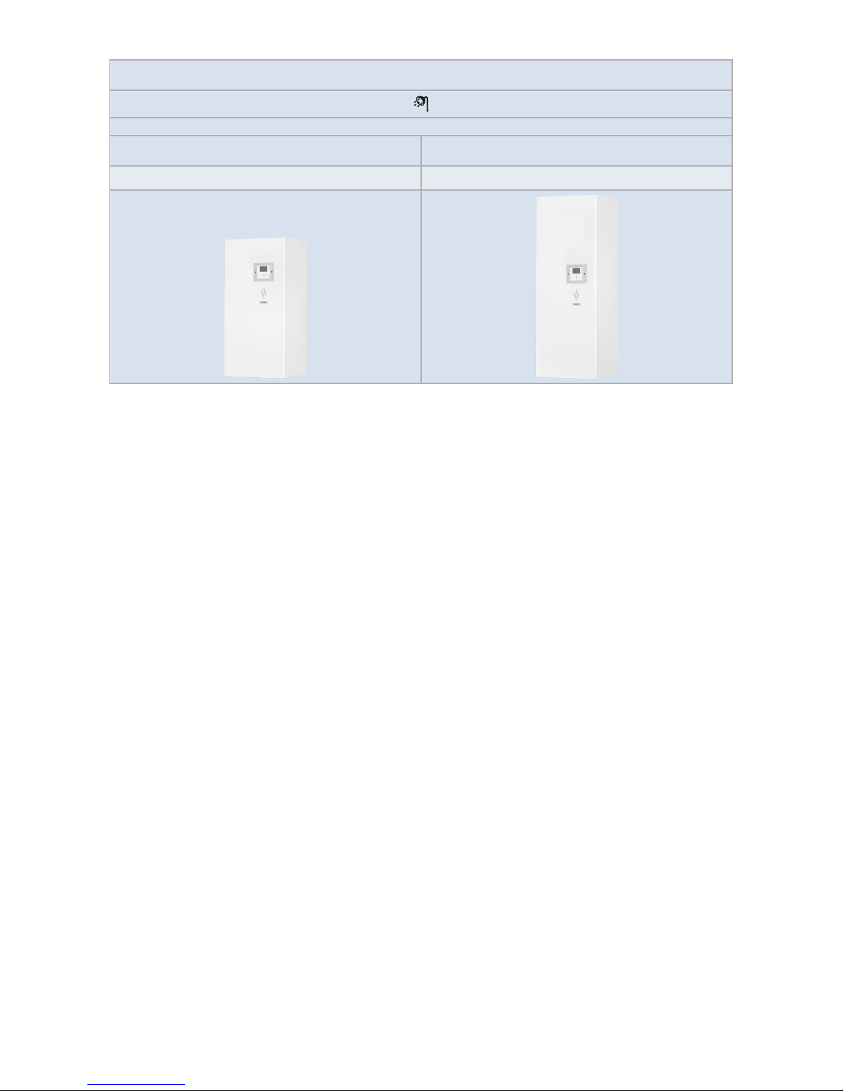
YUTAKI S80 DHW Tank - Depósito de ACS - Warmwasserspeicher - Ballon d’ECS - Serbatoio di ACD - Depósito de DHW -
Varmtvandsbeholder - Warmwaterketel - Tappvarmvattentank - Δεξαμενή DHW
1~ 230V 50Hz
Unit - Unidad - Gerät - Unité - Unità
- Unidade - Enhed - Unit - Enhet - Μονάδα
Unit - Uniidad - Gerät - Unité - Unità
- Unidade - Enhed - Unit - Enhet - Μονάδα
DHWS200S-2.7H2E DHWS260S-2.7H2E
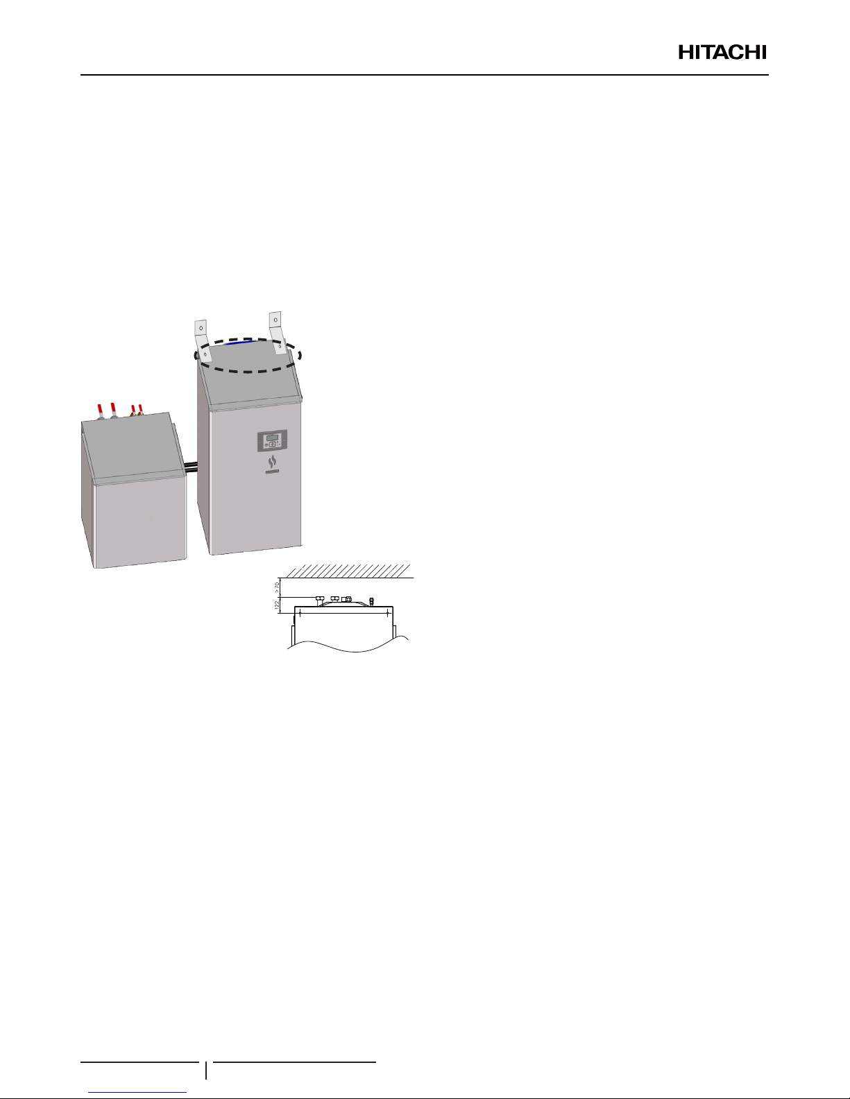
? NOTE
• The tank can be installed integrated above the indoor unit or
beside the indoor unit. In this case, the dedicated accessory kit
for installation with tank beside the indoor unit (ATW-FWP-02)
is required.
• Icons between brackets mean possible extra operations to the
factory-supplied operations.
? NOTA
• El depósito se puede instalar encima o al lado de la unidad
interior. En este último caso es necesario el kit accesorio
(ATW-FWP-02).
• Los iconos que se muestran entre paréntesis son posibles
funciones extra que se pueden añadir a las funciones de las
que la unidad dispone de fábrica.
? HINWEIS
• Der Speicher kann über dem Innengerät oder neben
dem Innengerät installiert werden. In diesem Fall ist das
vorgesehene Zubehör-Set (ATW-FWP-02) zur Installation des
Speichers neben dem Innengerät erforderlich.
• Die in Klammern stehenden Symbole bedeuten, dass
zusätzliche Betriebsfunktionen neben den werksseitig
bereitgestellten Betriebsfunktionen möglich sind.
? REMARQUE
• Le ballon peut être intégré au-dessus ou à côté de l’unité
intérieure. Dans ce cas, le kit dédié d’installation avec le ballon
à côté de l’unité intérieure (ATW-FWP-02) est nécessaire.
• Les icônes entre parenthèses indiquent d’éventuelles fonctions
additionnelles à celles fournies.
? NOTA
• Il serbatoio può essere installato integrato sopra l’unità interna
o accanto ad essa. In questo caso, è richiesto l’apposito kit
accessorio per l’installazione con il serbatoio accanto all’unità
interna (ATW-FWP-02).
• Le icone tra parentesi indicano possibili operazioni aggiuntive
oltre a quelle in dotazione.
? NOTA
• O depósito pode ser instalado sobre ou ao lado da unidade
interior. Neste caso, é necessário o acessório especíco
(ATW-FWP-02) para a instalação do depósito ao lado da
unidade interior.
• Os ícones entre parêntesis representam possíveis funções
suplementares relativamente às funções disponibilizadas de
fábrica.
? BEMÆRK
• Beholderen kan monteres oven på indendørsenheden eller ved
siden af indendørsenheden. I så fald skal man anvende det til
formålet beregnede tilbehørssæt til montering af beholder ved
siden af indendørsenheden (ATW-FWP-02).
• Symbolerne i parentes betyder mulige ekstra funktioner
foruden de fra fabrikken leverede funktioner.
? OPMERKING
• De warmwaterketel kan hetzij boven hetzij naast de binnenunit
worden gemonteerd. In dat laatste geval is een speciale
kit (ATW-FWP-02) nodig om de warmwaterketel naast de
binnenunit te installeren.
• De icoontjes tussen haken verwijzen naar extra functies naast
de standaardfuncties.
? OBS!
• Tanken kan byggas in ovanför eller bredvid inomhusenheten. I
detta fall så krävs den speciella tillbehörssatsen för installation
av tanken bredvid inomhusenheten (ATW-FWP-02).
• Ikoner inom parentes betyder att det nns möjliga
extrafunktioner för de medföljande funktionerna.
? ΣΗΜΕΙΩΣΗ
• Η δεξαμενή αυτή μπορεί να εγκατασταθεί πάνω ή δίπλα στην
εσωτερική μονάδα. Σ’ αυτή την περίπτωση, είναι αναγκαίο το
ειδικό κιτ εξάρτημα για εγκατάσταση με δεξαμενή δίπλα στην
εσωτερική μονάδα (ATW-FWP-02).
• Τα εικονίδια σε παρένθεση υποδηλώνουν πιθανές επιπλέον
λειτουργίες εκτός από αυτές που παρέχονται από το εργοστάσιο.

INDEX
1 GENERAL INFORMATION
2 SAFETY
3 GENERAL DIMENSIONS
4 REFRIGERANT AND WATER PIPING
5 ELECTRICAL AND CONTROL SETTINGS
6 INSTALLATION
7 DHW TANK OPERATION
8 CONTROL DEVICE SETTING
9 COMMISSIONING
10 MAINTENANCE
ÍNDICE
1 INFORMACIÓN GENERAL
2 SEGURIDAD
3 DIMENSIONES GENERALES
4 TUBERÍAS DE AGUA Y DE REFRIGERANTE
5 AJUSTES ELÉCTRICOS Y DE CONTROL
6 INSTALACIÓN
7 FUNCIONAMIENTO DEL DEPÓSITO DE AGUA CALIENTE
SANITARIA
8 AJUSTE DEL DISPOSITIVO DE CONTROL
9 PUESTA EN MARCHA
10 MANTENIMIENTO
INHALTSVERZEICHNIS
1 ALLGEMEINE INFORMATIONEN
2 SICHERHEIT
3 ALLGEMEINE ABMESSUNGEN
4 KÄLTEMITTEL- UND WASSERLEITUNGEN
5 ELEKTRISCHE UND STEUERUNGS-EINSTELLUNGEN
6 INSTALLATION
7 WARMWASSERSPEICHERBETRIEB
8 STEUERUNGS-EINSTELLUNG
9 INBETRIEBNAHME
10 WARTUNG
INDEX
1 INFORMATIONS GÉNÉRALES
2 SÉCURITÉ
3 DIMENSIONS GÉNÉRALES
4 TUYAUTERIE FRIGORIFIQUE ET D'EAU
5 RÉGLAGES DE COMMANDE ET ÉLECTRIQUES
6 INSTALLATION
7 FONCTIONNEMENT DU BALLON D'EAU CHAUDE
SANITAIRE
8 RÉGLAGE DES DISPOSITIFS DE CONTRÔLE
9 MISE EN SERVICE
10 MAINTENANCE
INDICE
1 INFORMAZIONI GENERALI
2 SICUREZZA
3 DIMENSIONI GENERALI
4 LINEE DELL'ACQUA E DEL REFRIGERANTE
5 IMPOSTAZIONI ELETTRICHE E DI CONTROLLO
6 INSTALLAZIONE
7 FUNZIONAMENTO DEL SERBATOIO DELL'ACQUA CALDA
DOMESTICA
8 IMPOSTAZIONI DEL DISPOSITIVO DI CONTROLLO
9 MESSA IN ESERCIZIO
10 MANUTENZIONE
ÍNDICE
1 INFORMAÇÃO GERAL
2 SEGURANÇA
3 DIMENSÕES GERAIS
4 TUBAGEM DE REFRIGERANTE E DE ÁGUA
5 AJUSTES DE CONTROLO E ELÉTRICOS
6 INSTALAÇÃO
7 FUNCIONAMENTO DO DEPÓSITO DE ÁGUA QUENTE
SANITÁRIA
8 AJUSTE DO CONTROLO DO DISPOSITIVO
9 COLOCAÇÃO EM FUNCIONAMENTO
10 MANUTENÇÃO
INDHOLDSFORTEGNELSE
1 GENEREL INFORMATION
2 SIKKERHED
3 GENERELLE MÅL
4 KØLEMIDDEL- OG VANDRØR
5 ELEKTRISKE INDSTILLINGER OG
KONTROLINDSTILLINGER
6 MONTERING
7 BETJENING AF DHW BEHOLDER
8 INDSTILLING AF STYREENHED
9 IDRIFTSÆTTELSE
10 VEDLIGEHOLDELSE
INHOUDSOPGAVE
1 ALGEMENE INFORMATIE
2 VEILIGHEID
3 ALGEMENE AFMETINGEN
4 KOUDEMIDDEL- EN WATERLEIDINGEN
5 ELEKTRISCHE EN BESTURINGSINSTELLINGEN
6 INSTALLATIE
7 DE WARMWATERKETEL BEDIENEN
8 INSTELLINGEN VAN BESTURING
9 IMBEDRIJFSSTELLING
10 ONDERHOUD
INNEHÅLLSFÖRTECKNING
1 ALLMÄN INFORMATION
2 SÄKERHET
3 ALLMÄNA MÅTT
4 KYL- OCH VATTENRÖR
5 EL- OCH STYRINSTÄLLNINGAR
6 INSTALLATION
7 DRIFT AV VARMVATTENTANK
8 INSTÄLLNING AV STYRENHET
9 DRIFTSÄTTNING
10 UNDERHÅLL
ΕΥΡΕΤΗΡΙΟ
1 ΓΕΝΙΚΕΣ ΠΛΗΡΟΦΟΡΙΕΣ
2 ΑΣΦΑΛΕΙΑ
3 ΓΕΝΙΚΕΣ ΔΙΑΣΤΑΣΕΙΣ
4 ΨΥΚΤΙΚΟ ΚΑΙ ΣΩΛΗΝΩΣΕΙΣ ΝΕΡΟΥ
5 ΡΥΘΜΙΣΕΙΣ ΗΛΕΚΤΡΙΚΩΝ ΣΤΟΙΧΕΙΩΝ ΚΑΙ ΕΛΕΓΧΟΥ
6 ΕΓΚΑΤΑΣΤΑΣΗ
7 ΛΕΙΤΟΥΡΓΙΑ ΔΕΞΑΜΕΝΗΣ DHW
8 ΡΥΘΜΙΣΗ ΣΥΣΚΕΥΗΣ ΕΛΕΓΧΟΥ
9 ΕΝΑΡΞΗ ΛΕΙΤΟΥΡΓΙΑΣ
10 ΣΥΝΤΗΡΗΣΗ
EN English Original version
ES Español Versión traducida
DE Deutsch Übersetzte Version
FR Français Version traduite
IT Italiano Versione tradotta
PT Português Versão traduzidal
DA Dansk Oversat version
NL Nederlands Vertaalde versie
SV Svenska Översatt version
EL Ελληνικα Μεταφρασμένη έκδοση

ENGLISH
1 GENERAL INFORMATION
No part of this publication may be reproduced, copied, led
or transmitted in any shape or form without the permission of
HITACHI Air Conditioning Products Europe, S.A.U.
Within the policy of continuous improvement of its products,
HITACHI Air Conditioning Products Europe, S.A.U. reserves
the right to make changes at any time without prior notication
and without being compelled to introducing them into products
subsequently sold. This document may therefore have been
subject to amendments during the life of the product.
HITACHI makes every effort to offer correct, up-to-date
documentation. Despite this, printing errors cannot be controlled
by HITACHI and are not its responsibility.
As a result, some of the images or data used to illustrate this
document may not refer to specic models. No claims will be
accepted based on the data, illustrations and descriptions
included in this manual.
2 SAFETY
2.1 APPLIED SYMBOLS
During normal heat pump system design work or unit
installation, greater attention must be paid in certain situations
requiring particular care in order to avoid injuries an damage to
the unit, the installation or the building or property.
Situations that jeopardise the safety of those in the surrounding
area or that put the unit itself a risk will be clearly indicated in
this manual.
To indicate these situations, a series of special symbols will be
used to clearly identify these situations.
Pay close attention to these symbols and to the messages
following them, as your safety and that of others depends on it.
! DANGER
• The text following this symbol contains information and
instructions relating directly to your safety and physical
wellbeing.
• Not taking these instructions into account could lead to serious,
very serious or even fatal injuries to you and others in the
proximities of the unit.
In the text following the danger symbol you can also nd
information on safe procedures during unit installation.
! CAUTION
• The text following this symbol contains information and instructions
relating directly to your safety and physical wellbeing.
• Not taking these instructions into account could lead to minor injuries
to you and others in the proximities of the unit.
• Not taking these instructions into account could lead to unit damage.
In the text following the caution symbol you can also nd
information on safe procedures during unit installation.
? NOTE
• The text following this symbol contains information or instructions that
may be of use or that require a more thorough explanation.
• Instructions regarding inspections to be made on unit parts or systems
may also be included.
2.2 ADDITIONAL INFORMATION ABOUT SAFETY
! DANGER
• DO NOT CONNECT THE POWER SUPPLY TO THE INDOOR UNIT
AND DHW TANK PRIOR TO FILLING BOTH CIRCUITS WITH
WATER AND CHECKING WATER PRESSURE AND THE TOTAL
ABSENCE OF ANY WATER LEAKAGE.
• Do not pour water over the electrical parts. If the electrical
components are in contact with water a seri ous electrical shock
will take place.
• Do not touch or adjust the safety devices inside the air to water
heat pump. If these devices are touched or adjusted, a serious
accident can take place.
• In case of re Turn OFF the main switch, put out the re at once
and contact your service contractor.
• It must ensure that the DHW tank cannot op erate accidentally
without water neither with air inside hydraulic system.
! CAUTION
• Do not use any sprays such as insecticide, lacquer, hair spray or other
ammable gases within approximately one meter from the system.
• If installation circuit breaker or the unit fuse is often activated, stop the
system and contact your service contractor.
• Do not make service or inspections tasks by yourself. This work must
be performed by a qualied service person.
• This appliance must be used only by adult and capable people,
having received the technical information or instructions to handle
this appliance properly and safely.
• Children should be supervised to ensure that they do not play with
the appliance.
• Do not let any foreign body into the water inlet and outlet piping of
the DHW tank.
GENERAL INFORMATION
PMML0344B rev.0 - 04/2016
1

2.3 IMPORTANT NOTICE
• The supplementary information about the purchased
products is supplied in a CD-ROM, which can be found
bundled with the indoor unit. In case that the CD-ROM is
missing or it is not readable, please contact your HITACHI
dealer or distributor.
• PLEASE READ THE MANUAL AND THE FILES ON THE
CD-ROM CAREFULLY BEFORE STARTING TO WORK ON
THE INSTALLATION OF THE AIR TO WATER HEAT PUMP
SYSTEM. Failure to observe the instructions for installation,
use and operation described in this documentation may
result in operating failure including potentially serious faults,
or even the destruction of the air to water heat pump system.
• This document contains the information referred to the
HITACHI DHW tank. The HITACHI DHW tank must be
connected with the YUTAKI S80 indoor unit TYPE 2 only.
Please, refer to the YUTAKI S80 Indoor unit Instruction
manual “PMML0340B” (space heating information) or
to the CD‑ROM bundled with the unit for the complete
information of the system.
• Verify, in accordance with the manuals which appear in the
outdoor, indoor unit and DHW tank, that all the information
required for the correct installation of the system is included.
If this is not the case, contact your distributor.
• HITACHI pursues a policy of continuous improvement in
product design and performance. The right is therefore
reserved to vary specications without notice.
• HITACHI cannot anticipate every possible circumstance that
might involve a potential hazard.
• This air to water heat pump has been designed for standard
water heating for human beings only. Do not use this for
other purposes such as for drying clothes, heating foods or
for any other heating process (except swimming pool).
• No part of this manual may be reproduced without written
permission.
• If you have any questions, contact your service contractor of
HITACHI.
• Check and make sure that the explanations of each part
of this manual correspond to your air to water heat pump
model.
• Refer to the models codication to conrm the main
characteristics of your system.
• Signal words (NOTE, DANGER and CAUTION) are used
to identify levels of hazard seriousness. Denitions for
identifying hazard levels are provided in initial pages of this
document.
• The operation modes of these units are controlled by the unit
controller.
• This manual should be considered as a permanent part of
the system. It gives a common description and information
for this system which you operate as well as for other
models.
• Keep the water temperature of the system above the
freezing temperature.
SAFETY
PMML0344B rev.0 - 04/2016
2
ENGLISH
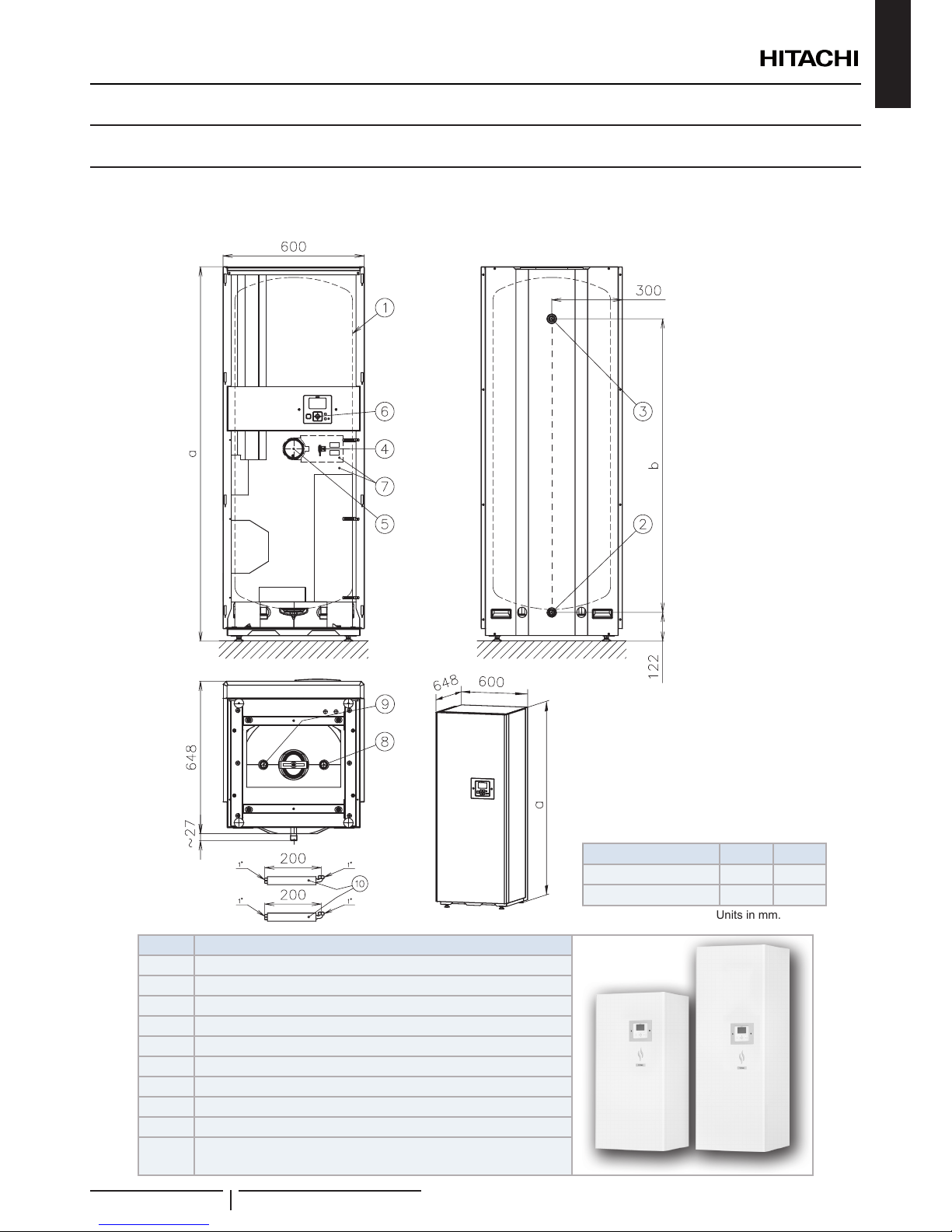
3 GENERAL DIMENSIONS
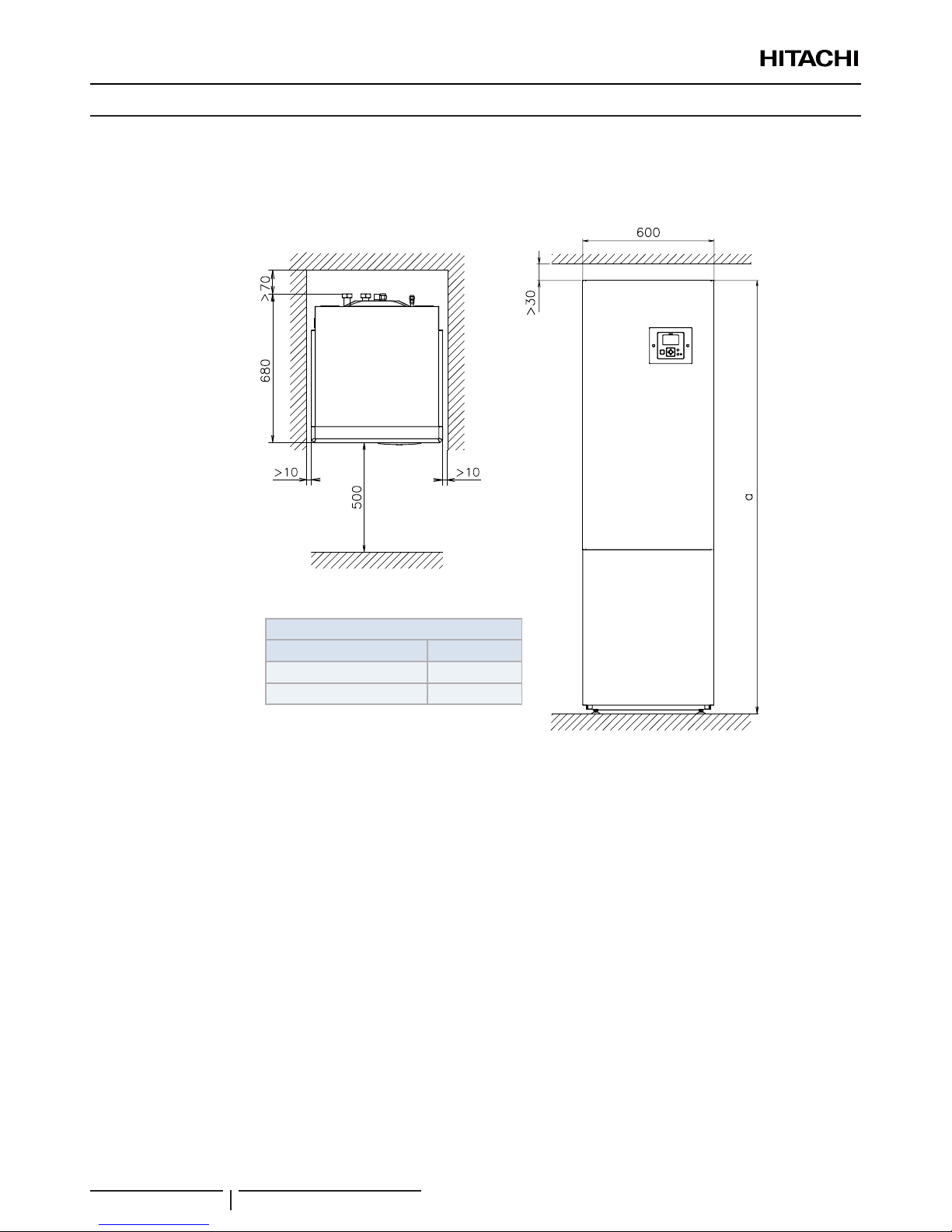
3.1 NAME OF PARTS AND DIMENSIONAL DATA
DHWS(200/260)S-2.7H2E
Front view Rear view
Top view
Unit/Dimension a b
DHWS200S-2.7H2E 1282 938.5
DHWS260S-2.7H2E 1591 1247.5
Dimensions according the unit
Units in mm.
XEKS 1719
Number Part name
1 Domestic hot water tank
2 DHW inlet G 3/4” male
3 DHW outlet G 3/4” male
4 DHW tank thermistor
5 Heater+ thermostat
6 Unit Controller
7 Tank insulation
8 Heating coil inlet connection G 1” male
9 Heating coil outlet connection G 1” male
10 Flexible pipe (x2)
GENERAL DIMENSIONS
PMML0344B rev.0 - 04/2016
3
3.2 SERVICE SPACE
3.2.1 Indoor unit TYPE 2 + Domestic hot water tank above the indoor unit
RWH-(4.0-6.0)(V)NFWE + DHWS(200/260)S-2.7H2E
Service with this space is possible
but, for an easier servicing of some
components it is recommended to
let a space >500mm
Units in mm.
Top view
Left side
Front view
Right side
>500mm
(Min. distance for
E-box removal)
(*) Minimum
distance for piping
connection back
outlet
Dimensions according to the unit (mm)
Unit Dimension "a"
RWH + DHWS200S-2.7H2E 1980
RWH + DHWS260S-2.7H2E 2289
GENERAL DIMENSIONS
PMML0344B rev.0 - 04/2016
4
ENGLISH
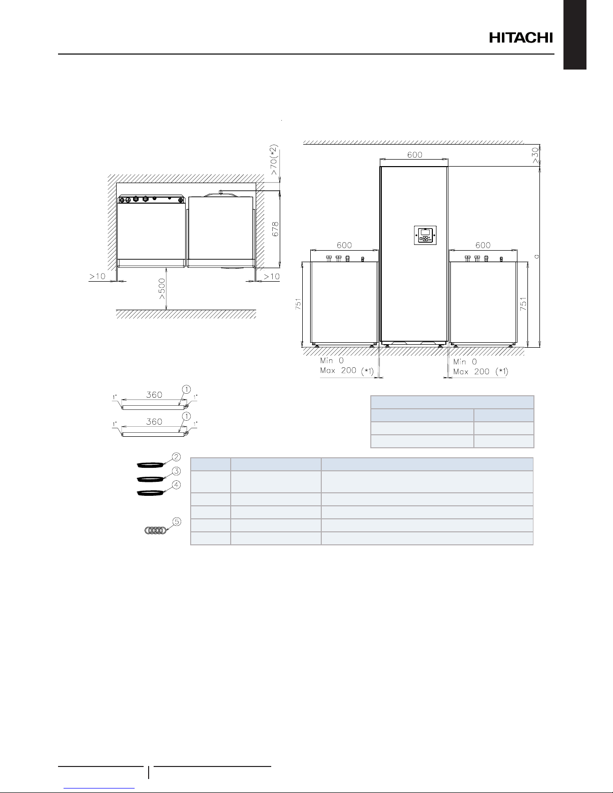
3.2.2 Indoor unit TYPE 2 + Domestic Hot water tank beside the indoor unit
RWH-(4.0-6.0)(V)NFWE + DHWS(200/260)S-2.7H2E
Units in mm.
Mark Part name Remarks
1 Flexible water pipe (x4)
For heating coil inlet and outlet connections of indoor unit
and DHW tank
2 Extension cables For tank electric heater
3 Extension cables For tank thermistor
4 Extension cables For unit controller
5 Gasket (x5) Gaskets (x5) for each exible water pipe end (+1 for spare)
Top view
Left side
Front view
Right side
>500mm (Min. distance
for E-box removal)
(*2) Minimum distance for
piping connection back
outlet
Dimensions according to the unit (mm)
Unit Dimension "a"
RWH + DHWS200S-2.7H2E 1980
RWH + DHWS260S-2.7H2E 2289
(*1) Recommended distance
between indoor unit and tank
may vary from 0 to 200 mm
Option 1
Option 2
Indoor unit at the
left side of tank
Indoor unit at the
right side of tank
Indoor unit
Tank
Service with this
space is possible
but, for an easier
servicing of some
components it is
recommended
to let a space
>500mm
GENERAL DIMENSIONS
PMML0344B rev.0 - 04/2016
5
4 REFRIGERANT AND WATER PIPING
4.1 SPACE HEATING AND DHW
! DANGER
Do not connect the power supply to the indoor unit prior to lling the space heating and DHW circuit with water and checking water pressure
and the total absence of any water leakage.
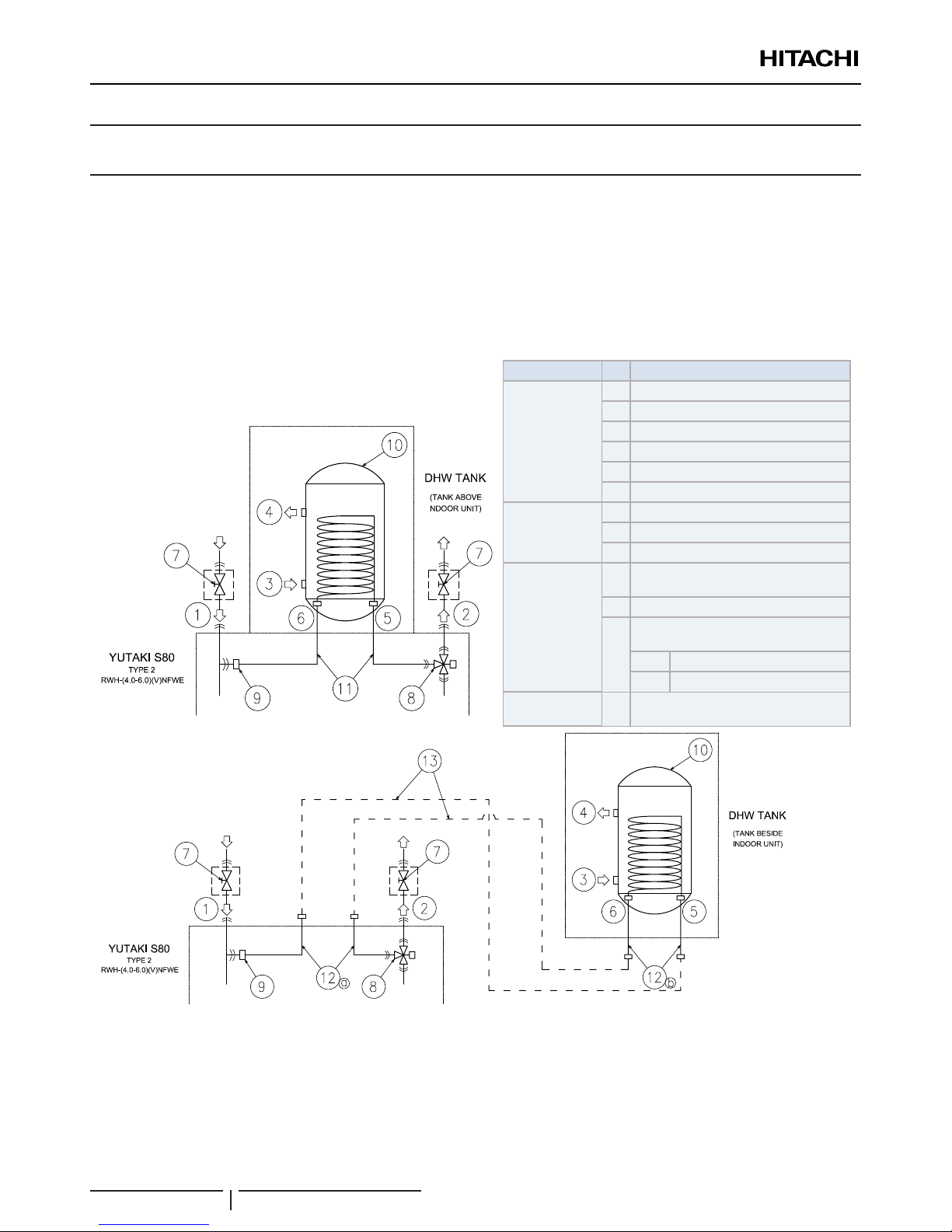
4.1.1 Additional hydraulic necessary elements for DHW
TYPE 2: Version for operation with Hitachi DHW tank
Type Nº Part name
Piping
connections
1 Water inlet (Space heating)
2 Water outlet (Space heating)
3 Heating coil inlet
4 Heating coil outlet
5 Water inlet (DHW)
6 Water outlet (DHW)
Factory supplied
7 Shut-off valve (factory-supplied)
8 3-way valve
9 T-branch
Accessories
10
Domestic hot water tank
(DHWS(200/260)S-2.7H2E accessory)
11 Heating coil pipes
12
Flexible water pipe kit
(ATW-FWP-02 accessory)
12a Indoor unit pipes
12b DHW tank pipes
Field supplied 13
Water pipes between indoor unit and
DHW tank
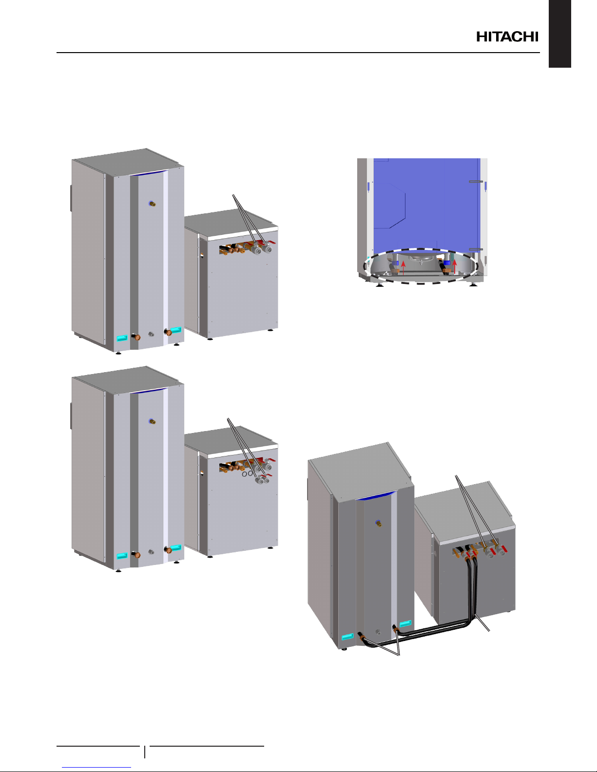
DHW tank integrated
above the indoor unit
DHW tank beside the
indoor unit
When installing the YUTAKI S80 indoor unit TYPE 2 (RWH-(4.0-6.0)(V)NFWE) in combination with the HITACHI DHW tank
(DHWS(200/260)S-2.7H2E) the following elements to provide DHW operation are needed:
• The YUTAKI S80 domestic hot water tank (DHWS(200/260)S‑2.7H2E accessory) (10) is required in combination with YUTAKI
S80 indoor unit. This tank accessory is factory-supplied with two exible water pipes (11). Respect the following instructions
depending on the DHW tank location (integrated above the indoor unit or beside it).
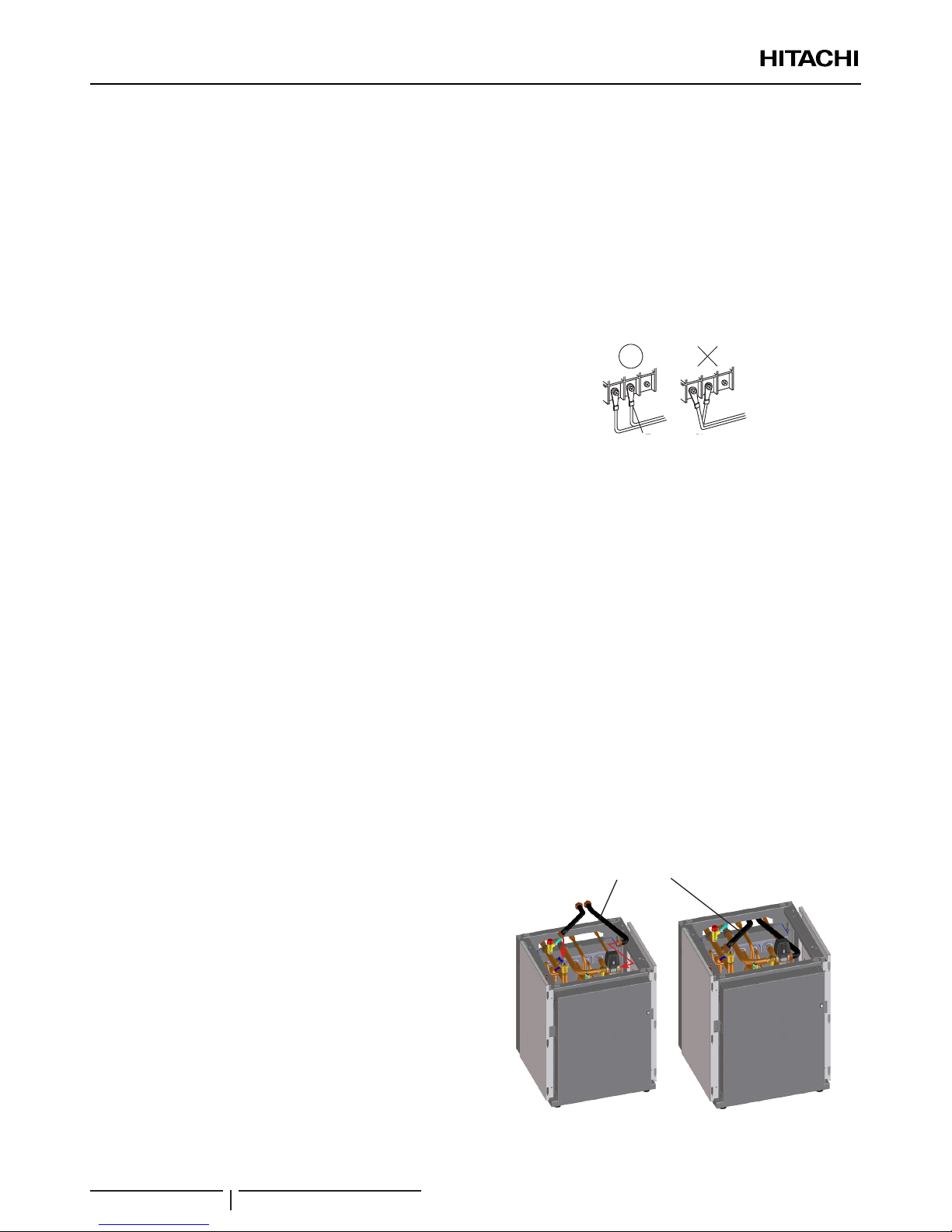
- For DHW tank integrated above the indoor unit, use one of the factory-supplied pipes (11) for the connection between 3-way
valve and the heating coil inlet coil of the DHW tank, and the other one for the connection between the T-branch and the
heating coil outlet coil of the DHW tank accessory.
REFRIGERANT AND WATER PIPING
PMML0344B rev.0 - 04/2016
6
ENGLISH
- For DHW tank beside the indoor unit (both right or left side), the pipes factory-supplied with the DHW tank accessory (11) are
not required. In this case, the dedicated HITACHI exible water pipe kit (ATW-FWP-02 accessory) (12) is needed. This kit is
provided with the following items:
4 exible water pipes (Two pipes (12a) to connect to the indoor unit (3-way (8) valve and T-branch (9)) and other two
pipes (12b) to connect to the heating coil inlet/outlet connections of the DHW tank (5-6). To connect the indoor unit with
the DHW tank, two additional eld-supplied pipes are required (13).
9 gaskets (2 gaskets for each exible water pipe end and 1 spare gasket).
3 extension cables (1 for the tank’s electric heater, 1 for the tank’s thermistor and 1 for the unit controller).
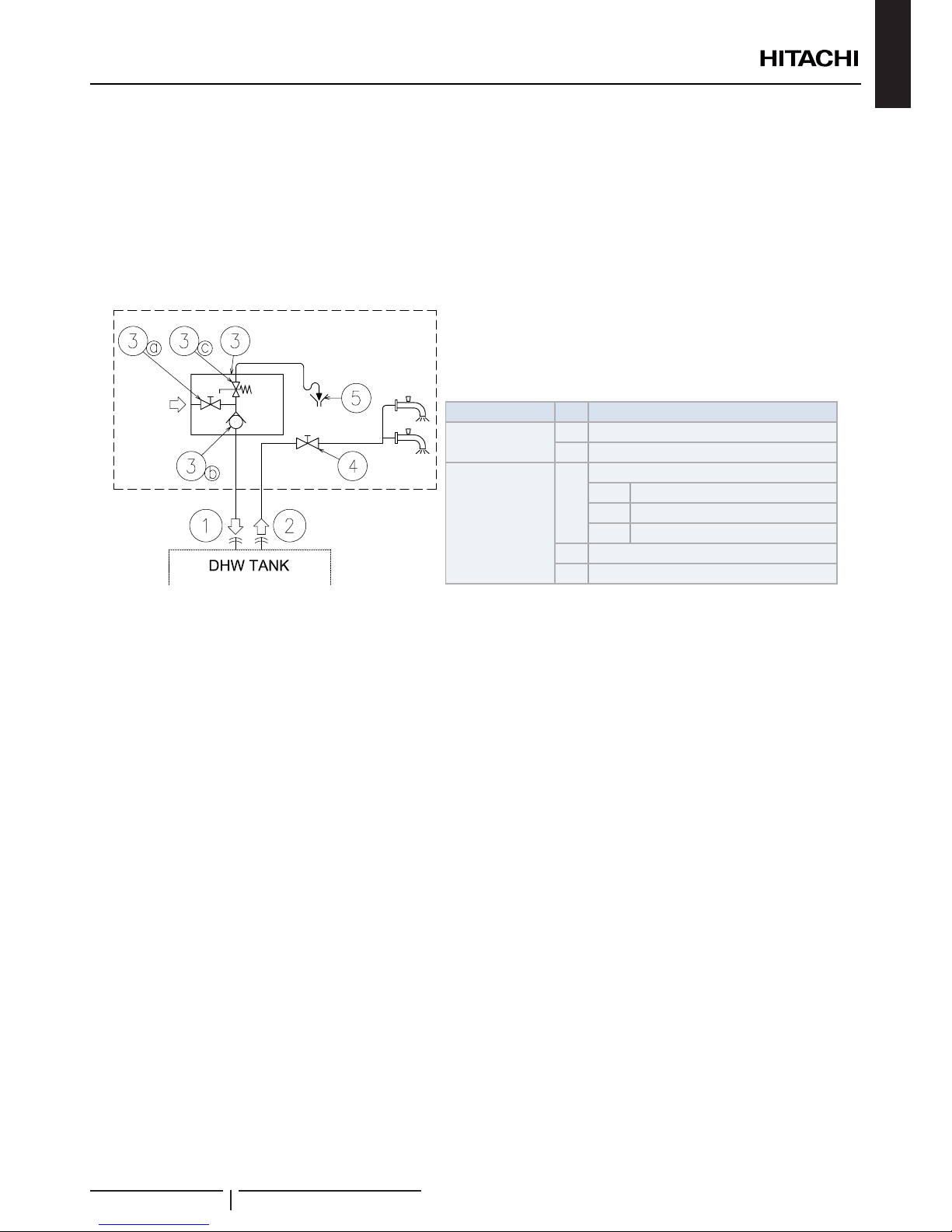
Additionally, the following elements are required for the DHW circuit:
Type Nº Part name
Piping connections
1 Water inlet (DHW)
2 Water outlet (DHW)
Field supplied
3
Pressure and temperature relief valve
3a Shut-off valve
3b Water check valve
3c Pressure relief valve
4 Shut-off valve
5 Draining
• 1 Shut-down valve (eld supplied): one shut-down valve (4) must be connected after the DHW outlet connection of the DHW
tank (2) in order to make easier any maintenance work.
• A Security water valve (Field‑supplied): this accessory (3) is a pressure and temperature relief valve that must be installed as
near as possible to the DHW inlet connection of the DHW tank (1). It should ensure a correct draining (5) for the discharge valve
of this valve. This security water valve should provide the following:
- Pressure protection
- Non-return function
- Shut-down valve
- Filling
- Draining
? NOTE
The discharge pipe should always be open to the atmosphere, free of frost and in continuous slope to the down side in case that water leakage exists.
REFRIGERANT AND WATER PIPING
PMML0344B rev.0 - 04/2016
7
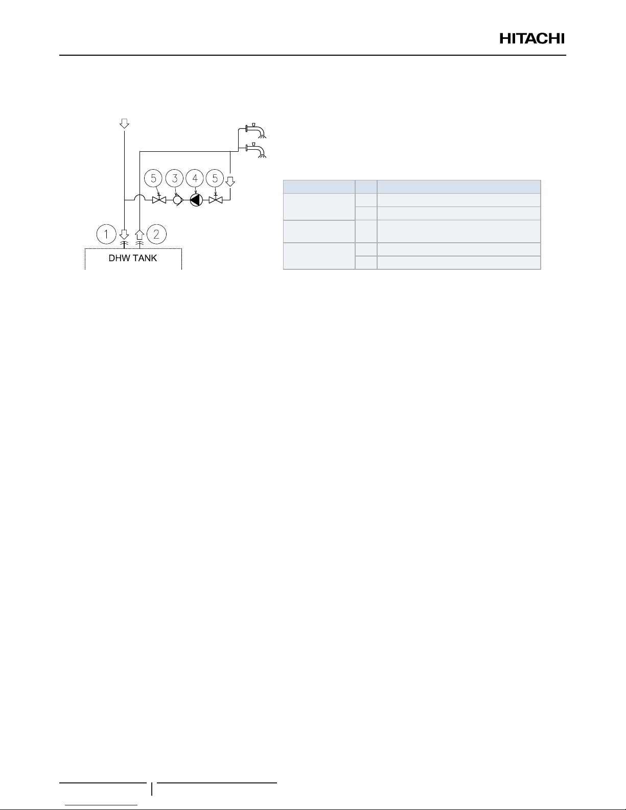
4.1.2 Additional hydraulic optional elements (For DHW)
In case of a recirculation circuit for the DHW circuit:
Type Nº Part name
Piping connections
1 Water inlet (DHW)
2 Water outlet (DHW)
Accessories 3
Water check valve
(ATW-WCV-01 accessory)
Field supplied
4 Water pump
5 Shut-off valve
• 1 Recirculation water pump (eld supplied): this water pump (3) will help to correctly recirculate the hot water to the DHW
inlet.
• 1 Water check valve (ATW-WCV-01 accessory): this Hitachi accessory (4) is connected after the recirculation water pump (31)
in order to ensure the non-return of water.
• 2 Shut-down valves (eld supplied) (5): one before the recirculation water pump (3) and other after the water check valve
accessory (4).
4.1.3 Requirements and recommendations for
the hydraulic circuit
• The storage capacity of the tank has to meet with the daily
consumption in order to avoid stagnation of water.
• Fresh water must circulate inside the DHW tank water
circuit at least one time per day during the rst days after
the installation has been performed. Additionally, ush the
system with fresh water when there is no consumption of
DHW during long periods of time.
• Try to avoid long runs of water piping between the tank
and the DHW installation in order to decrease possible
temperature losses.
• When using the indoor unit in combination with the YUTAKI
S80 DHW tank, the heating coil of the tank is placed in a
higher position than the indoor unit air purger. Then, to totally
purge the space heating circuit, it is very important that the
heating coil of the tank is fully air purged.
• lf the domestic cold water entry pressure is higher than the
equipment’s design pressure (6 bar), a pressure reducer
must be tted with a nominal value of 7 bar.
• Ensure that the installation complies with applicable
legislation in terms of piping connection and materials,
hygienic measures, testing and the possible required use of
some specic components like thermostatic mixing valves,
Differential pressure overow valve, etc.
• Make sure that all eld supplied components installed in the
piping circuit can withstand the water pressure and the water
temperature range in which the unit can operate.
• Do not add any type of glycol to the water circuit.
4.1.4 Water lling
Heating coil circuit
Fill the DHW tank heating coil from the space heating circuit
lling in point. Follow the instructions explained in the “4.1
Space heating and DHW” chapter to correctly perform the
operation.
! CAUTION
• Check that the heating coil pipes are correctly connected between
indoor unit and tank before lling the tank’s heating coil.
• Ensure the correct water quality of the indoor unit water circuit.
Domestic hot water tank and DHW circuit
1 Open the outlet water taps of the DHW installation one after
each other, to expel all the air from inside the water circuit.
2 Open the main DHW inlet valve in order to ll the tank. If
there is a shut-off valve installed in the DHW outlet, open it
to allow circulation through the DHW installation.
3 When water begins to ow from the outlet water taps of the
DHW installation, close all these taps.
4 Finally, close the main DHW inlet valve when the pressure
reaches approximately 6 bars.
! CAUTION
• Check carefully for leaks in the water circuit, connections and circuit
elements.
• Check that the water pressure in the circuit is lower than 7 bars.
• A pressure and temperature relief valve should be installed at the
DHW inlet connection of the tank. If it is the case, manually operate its
relief valve to ensure that the water ows free through the discharge
pipe.
• Fill in the circuit with tap water. The water in the heating installation
must comply with EN directive 98/83 EC. Non-sanitary controlled
water is not recommended (for example, water from wells, rivers,
lakes, etc.).
REFRIGERANT AND WATER PIPING
PMML0344B rev.0 - 04/2016
8
ENGLISH
5 ELECTRICAL AND CONTROL SETTINGS
5.1 GENERAL CHECK
• Make sure that the following conditions related to power supply installation are satised:
- The power capacity of the electrical installation is large enough to support the power demand of the YUTAKI system (outdoor
unit + indoor unit + DHW tank).
- The power supply voltage is within ±10% of the rated voltage.
- The impedance of the power supply line is low enough to avoid any voltage drop of more than 15% of the rated voltage.
• Check to ensure that existing installation (mains power switches, circuit breakers, wires, connectors and wire terminals) already
complies with the national and local regulations.
• The use of the DHW tank heater is disabled as factory setting. If it is desired to enable the DHW tank heater operation during
normal indoor unit operation, adjust the DSW4 pin 3 of the PCB1 to the ON position and use the adequate protections.
• Check to ensure that the eld supplied electrical components (mains power switches, circuit breakers, wires, connectors and
wire terminals) have been properly selected according to the electrical data indicated on this chapter and they comply with
national and local codes. If it is necessary, contact with your local authority in regards to standards, rules, regulations, etc.
• Ensure specically that there is an Earth Leakage Breaker (ELB) installed for the units (indoor, outdoor and the optional DHW
tank).
• If the installation is already equipped with an Earth Leakage Breaker (ELB), ensure that its rated current is large enough to hold
the current of the units (indoor, outdoor and the optional DHW tank).
! DANGER
• Do not connect the power supply to the indoor unit and DHW tank prior lling of water both circuits and checking water pressure and
the total absence of any water leak.
• Never connect the DHW tank to the main power supply. Always connect it to the YUTAKI S80 indoor unit as explained in the
“6 INSTALLATION” chapter.
• Do not connect or adjust any wiring or connections unless the main power switch is OFF.
5.2 ELECTRICAL WIRING BETWEEN INDOOR UNIT AND DHW TANK
? NOTE
Please, refer to the YUTAKI S80 indoor unit Installation and operation manual, to know the specic protection for the combination of indoor unit and
DHW tank.
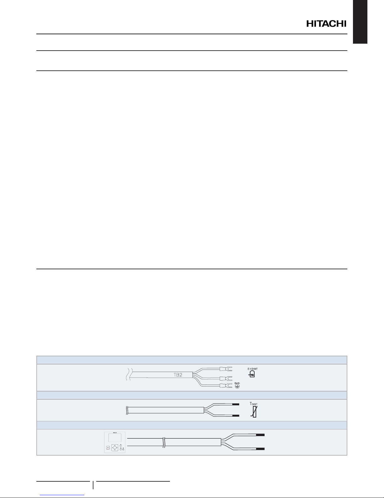
Factory supplied wire sizes
The supplied wires for the connection between the DHW tank and the indoor unit are already connected to the DHW tank. They
are located at the bottom front side of the tank fastened with clamps. The Unit controller electrical cable at the right and the electric
heater and thermistor cables at left.
Electric heater connection cable
30(N)
31(L)
}
Thermistor connection cable
5
6
Unit controller connection cable
3(A)
4(B)
OK
ELECTRICAL AND CONTROL SETTINGS
PMML0344B rev.0 - 04/2016
9
Model Power supply
Maximum
current
(A)
Unit controller
connection cable size
Electric heater
connection cable size
Thermistor connection
cable size
EN60335-1 EN60335-1 EN60335-1
DHWS200S-2.7H2E
1~ 230V 50Hz 8.7 6 x 0.5 mm2 x 1.8m 3 x 2.5 mm2 x 1.8m 2 x 0.3 mm2 x 2.0m
DHWS260S-2.7H2E
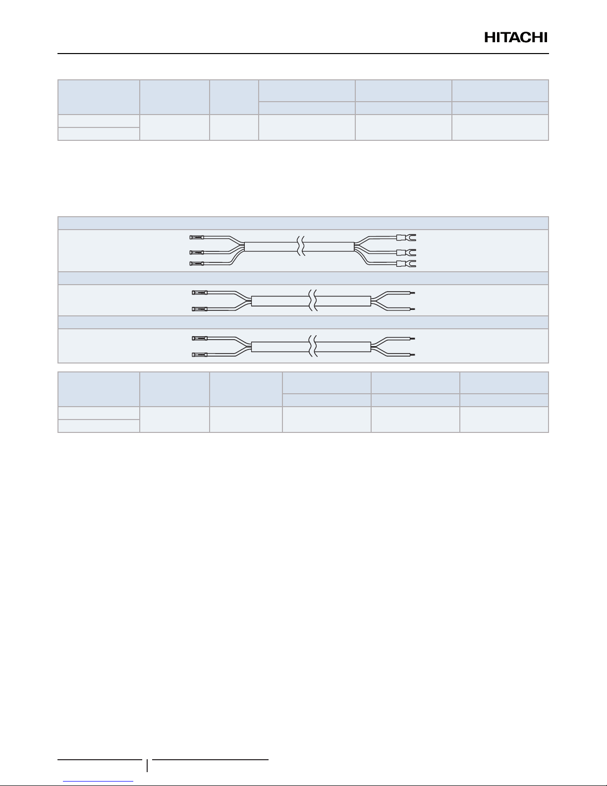
Extension cables (supplied with the ATW-FWP-02 accessory. Only for installation of the DHW tank
beside the indoor unit)
When the domestic hot water tank is installed beside the indoor unit, it is needed to extend the cables up to the terminal board 2
(TB2) of the indoor unit, which is placed at certain distance from the tank. These cables are the following:
Extension cable for the electric heater
Extension cable for the thermistor
Extension cable for the LCD controller
Model Power supply
Maximum current
(A)
Unit controller
extension cable size
Electric heater
extension cable size
Thermistor extension
cable size
EN60335-1 EN60335-1 EN60335-1
DHWS200S-2.7H2E
1~ 230V 50Hz 8.7 6 x 0.5 mm2 x 3.5m 3 x 2.5 mm2 x 3.5m 2 x 0.3 mm2 x 3.5m
DHWS260S-2.7H2E
ELECTRICAL AND CONTROL SETTINGS
PMML0344B rev.0 - 04/2016
10
ENGLISH
6 INSTALLATION
6.1 GENERAL NOTES
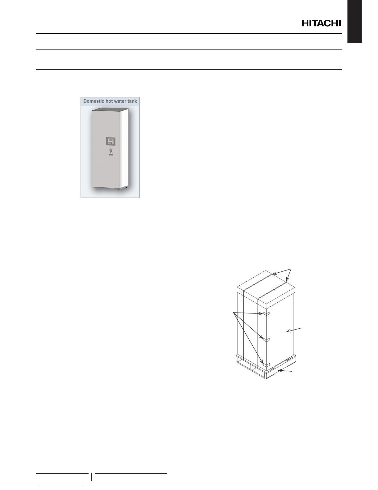
6.1.1 Components at receipt
Domestic hot water tank
? NOTE
The unit controller (PC-ARFHE) is integrated in the DHW tank.
6.1.2 Selection of the installation location
The domestic hot water tank must be installed following these
basic requirements:
• The tank is intended to be installed in an indoor place.
• The tank is prepared to be integrated over the YUTAKI
S80 indoor unit, so make sure that selected oor is at
and is made of a non-combustible surface, strong enough
for supporting the indoor weight and also the DHW tank’s
weight completely water lled.
• The tank can be also oor mounted (Tank beside the indoor
unit both left or right sides). In this case, try to keep an
access point for the connection of the dedicated Flexible
Water Pipes Kit (ATW-FWP-02).
• Be sure to maintain the recommended servicing space for
future unit servicing (See “3.2 Service space” section).
• It is necessary to plan a xing point between the wall and the
DHW tank.
• Take into account the space needed to install a necessary
pressure and temperature relief valve, which must be
installed at the DHW inlet connection of the tank (as close as
possible to the tank). 1 shut-off valve (eld supplied) must be
also installed at the DHW outlet connection.
• Keep water draining provisions. The safety valve and the air
purge are provided with a drain pipe which are located at the
bottom side of the indoor unit.
• Protect the DHW tank unit against the entry of small animals
(like rats) which could making contact with the wires, the
drain pipe, electrical parts and may damage unprotected
parts, and at the worst, a re will occur.
• Install it in a no-frost environment.
• Install the DHW tank as far as possible from all sources of
electromagnetic wave radiation.
• Install the unit in a place where in case of water leakage,
any damage to the installation space cannot be produced.
• To avoid re or explosion, do not install the set in a
ammable environment.
• The tank must be installed by a service technician.
The installation must comply with local and European
regulations.
6.1.3 Unpacking
All units are supplied with a wooden base, packed by a
cardboard box and plastic bag.
Firstly to unpack it, place the unit on the assembly area as close
as possible to its nal installation location, to avoid damages in
transport. Two persons are required.
1 Cut the strapping bands and remove the adhesive tapes.
2 Remove the carton assembly and then the plastic bag
around the unit.
3 Unscrew the 4 screws which x the unit to the wooden base.
4 Remove the indoor unit from the wooden base and place it
carefully on the oor, as near as possible to its nal location.
Wooden
base
Carton
assembly
Strapping
bands
Adhesive
tapes
! CAUTION
• There are four adjustable mounting foot at the bottom of the unit.
Each one can be adjusted up to 30 mm, but keep the mounting foot
in the factory supplied position until the unit has been installed in its
nal position.
• Be careful with the Installation and Operation manual and with the
accessories factory-supplied with the unit.
• Two people are required when lifting because of the weight of the
unit.
INSTALLATION
PMML0344B rev.0 - 04/2016
11
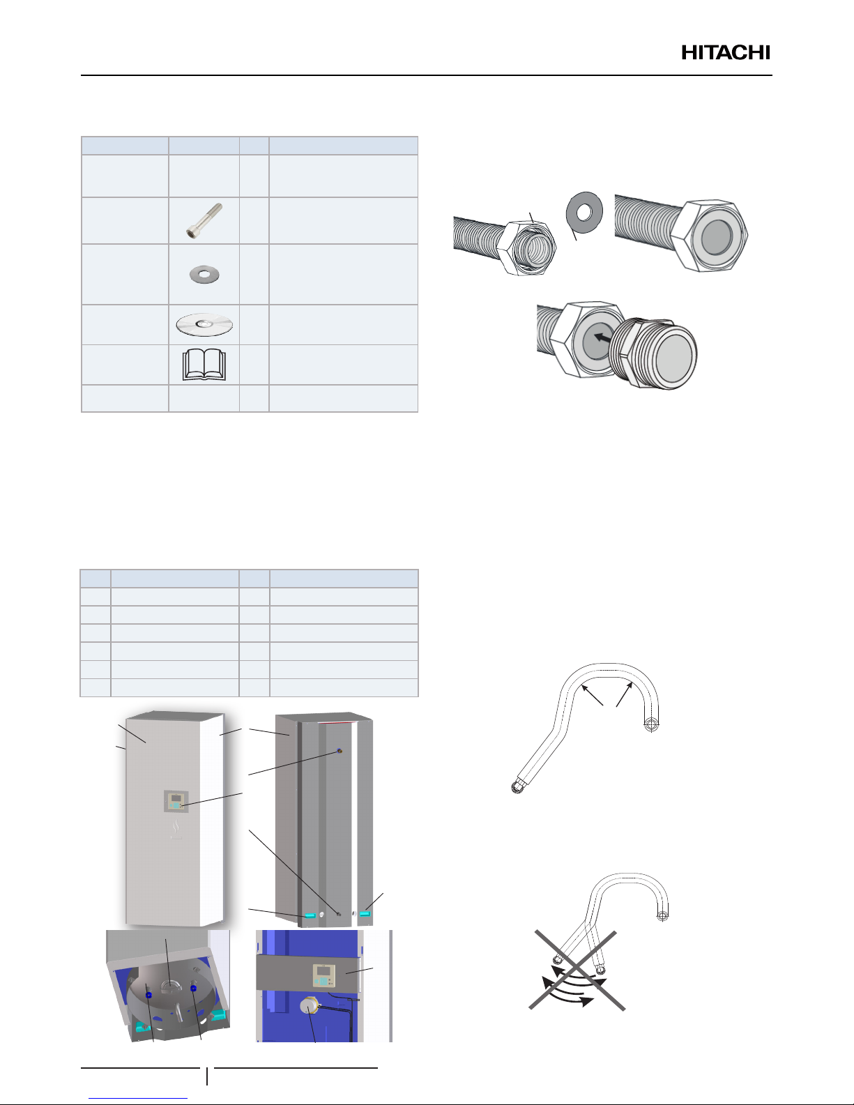
6.1.4 Factory-supplied indoor unit components
Accessory Image Qty. Purpose
Flexible water
pipe (1”)
2
Heating coil pipes (for
connection between indoor
unit and DHWT)
M10 bolts 4
To x the tank to the indoor
unit
Gaskets 4+2
4 x1”for the heating coil pipes
2 x3/4” for the DHW
connection
CD-ROM 1
With the detailed Installation
and operation manual
Instruction
manual
1
Basic instructions for the
installation of the device.
Declaration of
conformity
- 1 -
? NOTE
• The previous accessories are supplied inside the packing assembly
(in the accessory box).
• Additional refrigerant piping (eld supplied) for connections to indoor
unit needs to be available.
• If some of these accessories are not packed with the unit or any
damage to the unit is detected, please contact your dealer.
6.1.5 DHWT main parts (Descriptions)
Nº Part Nº Part
1 Front cover 7 Handles
2 Left cover 8 Heating coil inlet (G1” male)
3 Right cover 9 Heating coil outlet (G1” male)
4 DHW outlet (G3/4” male) 10 “Inspection” hatch
5 Unit controller 11 DHWT electric heater
6 DHW inlet (G 3/4” male) 12 LCD support
1
2
7
3
5
4
6
7
12
9
8
10
11
6.1.6 Flexible water coil pipes considerations
Process for coil pipes connection (to avoid leakage).
1 Put a gasket inside the nut.
a)
b)
c)
Gasket
Nut
2 Check that the nut turns free.
3 Be sure that the tube is aligned with the connection.
4 IMPORTANT! Ensure that the gasket is in contact and it is
seating uniformly with the connection.
5 By hand, rotate smoothly the nut and screw it into the
connection. The screwing may be easy and it should not
offer too much resistance, so if that happens, loosen the nut
and check that the pipe and the gasket position are correct
and proceed again with point 3 and 4.
6 With a spanner, nish the screwing process of the nut until
rm but without damaging the gasket.
? CAUTION
• Always bend the water tubes with a radius > 90 mm.
R>90mm
• The tube will not spring back.
• Don’t install the stainless steel tube in a twisted position.
• Don’t bend these stainless steel tube more often than
required to avoid breaking it.
INSTALLATION
PMML0344B rev.0 - 04/2016
12
ENGLISH
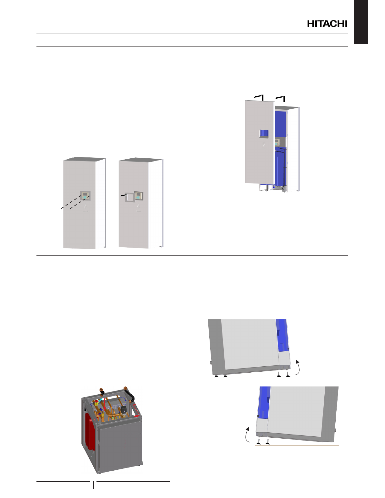
6.2 REMOVING THE FRONT COVER
For the installation of the tank it is necessary to remove the front
cover of the DHWT to get access to the inner parts.
? NOTE
• The pictures shown correspond to DHWS260S-2.7H2E, but
the procedure for removing covers is exactly the same for the
DHWS200S-2.7H2E.
• Front cover needs to be removed for any task inside the unit.
Removing the front cover
1 Unscrew the 2 xing screws of the Unit controller frame.
Gently pull the unit controller frame backwards.
! CAUTION
Take care wit the LCD display when removing the unit controller frame.
2 Pull the front cover upwards and the backward to remove it.
! CAUTION
• Pay attention of no falling off the front cover.
• Be careful not to damage the LCD display and/or the unit controller
itself when removing the front cover.
6.3 INSTALLATION OF DHW TANK WITH YUTAKI S80 INDOOR UNIT
6.3.1 Version with tank on top of the indoor
unit
? NOTE
Please, try to perform all this procedure following all the steps in the exact
order in which they are presented below.
Installation procedure
1 Water pipes connection to the indoor unit (space heating
pipes).
? NOTE
• Pipes are already preformed from factory. This pre-bend side
should be connected to the S80 indoor unit.
• When connected to the S80 indoor unit, pre-form the pipes in
order to let the non connected end pointing to the top.
2 Remove the mounting foot from the tank (mounting foot
are assembled from factory and should be removed when
installing the tank on the top of the YUTAKI S80 indoor unit).
• Tilt the tank to one side so that the mounting feet are free to
be unscrewed. When screwed, repeat the same operation to
the other side to remove the remaining feet.
INSTALLATION
PMML0344B rev.0 - 04/2016
13
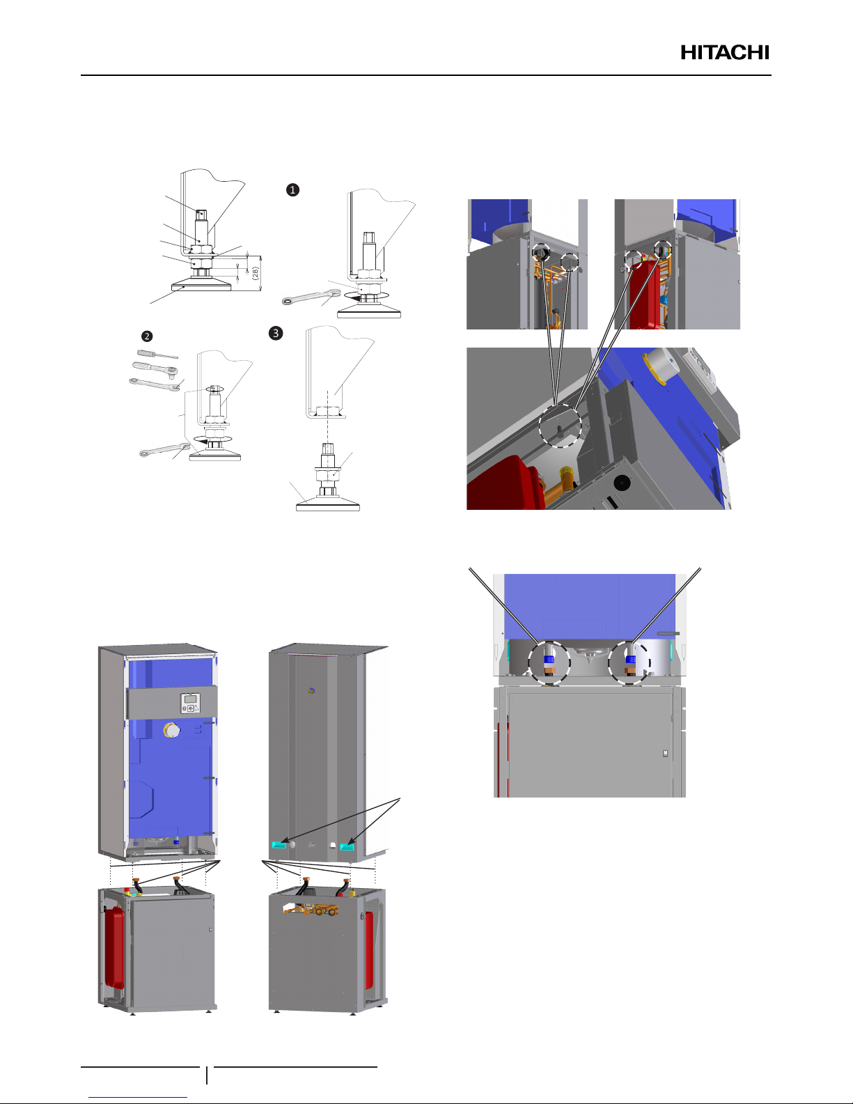
• Loosen the locknut of the mounting foot using a wrench.
• Turn the mounting foot anticlockwise to remove it (Use the
hexagon or slot designed for this purpose in the shaft end)
5
8
Hexagon and slot
for help in the foot
removal procedure
Threaded shaft
Welded nut
Locknut
Mounting
foot base
17 mm
Loosen locknut
7 mm
10 mm
Remove the
mounting foot
Locknut
Mounting
foot base
3 Assemble the tank on the S80 indoor unit
• Lift the tank using the handles placed at the rear of the
indoor unit
! CAUTION
The tank is too heavy. This procedure must be done with two persons
or serious lesions may occur.
Handles
Alignment
of bolts
4 Place the tank on the top of the indoor unit aligning the
welded nuts of the tank unit with the screw holes of the
YUTAKI S80 indoor unit.
5 Screw the M10 bolts (factory supplied) to join the indoor unit
with the tank.
6 Connect the pre-bend pipes to the coil of the tank unit.
Front
view
Heating coil inlet
connection (G 1” male)
Heating coil outlet
connection (G 1” male)
DHW tank
YUTAKI S80
Indoor unit
• The pipe connected to the 3-way valve must be connected
to the heating coil inlet connection of the tank.
• The pipe connected to the T-branch must be connected to
the heating coil ouconnection of the tank.
INSTALLATION
PMML0344B rev.0 - 04/2016
14
ENGLISH
7 Connection of the water pipes to the DHW installation.
• Connect the pipes of the DHW installation to the inlet and
outlet connections of the DHW tank.
DHW outlet connection
(G 3/4” male)
Rear view
DHW outlet connection
(G 3/4” male)
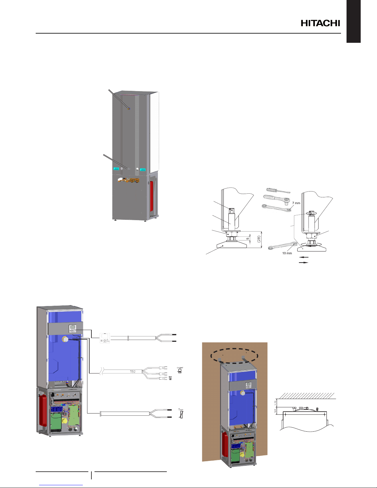
8 Connetion of the tank wiring to the indoor unit.
• The three electrical wires are already connected to the DHW
tank. They are located at the front side of the DHW tank
fastened with clamps.
• Take the three cables and drive them through the rubber
grommets in the partition plate at the bottom of the tank unit
and again through the rubber grommets at the rear side of
the Ebox.
• Connect each cable in the correct place according to the
wiring diagram. (See next picture)
30(N)
31(L)
}
5
6
3(A)
4(B)
OK
Electric heater connection cable
Thermistor connection cable
Unit controller connection cable
9 Levelling procedure
Once the connections of the tank have nished, it is
necessary to levelling the unit.
? NOTE
• Adjust only the necessary mounting foot of the unit.
• Start with all four feet screwed in as far as possible (factory
supplied position).
• Two people are necessary for the levelling procedure.
Follow the process:
Turn the mounting foot to extend the height (use the
hexagon or slot designed for this purpose in the shaft end).
! CAUTION
• Take care do not turn the weld nut when turning the mounting foot.
Use an slot with a height prole lower than 5 mm.
• Never work on more than one foot at the same time. When
nishing, all 4 lock-nuts must be tightened rmly.
Foot
Weld nut
Threaded
shaft
Hexagon and
slot for help
in the foot
adjustment
process
Adjust the
foot’s height as
needed
(2 options)
Extend
Take in
!
10 Tank xation to the wall
In case of indoor unit with integrated tank it is mandatory,
when there is not upper restriction, to x the domestic hot
water tank to the wall in order to provide a higher stability.
The accessory and screws for that purpose are eld
supplied.
The distance and measure are shown in the next picture.
• Fix the accessory to the DHW tank on the upper cover
through the holes.
122 mm: minimum distance
between the end of the male
tting and the wall xing hole
INSTALLATION
PMML0344B rev.0 - 04/2016
15
? NOTE
Use the accessory slotted hole to x the DHW tank to the wall at the
desired distance.
• Fix the accessory to the wall with eld supplied screws.
? NOTE
Check that the set (indoor unit with integrated tank) is installed totally
vertical.
11 Test and check.
Before assembling the covers, test and check the following
items:
• Water leakage
• Refrigerant leakage
• Electrical connection
• ...
? NOTE
The following documents must be referred:
• Refer to the chapters “4.1.4 Water lling” and “9 COMMISSIONING”
in this document (Tank)
• Refer to the YUTAKI S80 indoor unit Installation and operation
manual, for the information about the refrigerant charge, water
lling and Commissioning of the indoor unit.
• For the specic details about refrigerant charge tasks refer the
Outdoor unit Installation and Operation manual.
! DANGER
DO NOT CONNECT THE POWER SUPPLY TO THE INDOOR UNIT
AND DHW TANK PRIOR TO FILLING BOTH CIRCUITS WITH
WATER AND CHECKING WATER PRESSURE AND THE TOTAL
ABSENCE OF ANY WATER LEAKAGE.
12 Cover’s assembly
Finally, reassembly all the cover’s removed.
Safety instructions
? NOTE
Check the requirements and recommendations in the chapter “5 Electrical
and control settings”
! DANGER
• Do not connect the power supply to the DHW tank prior to
lling the space heating circuit and DHW circuit with water and
checking water pressure and the total absence of any water
leakage.
• Do not connect or adjust any wiring or connections unless the
main power switch is OFF.
• When using more than one power source, check and ensure that
all of them are turned OFF before operating the unit.
• Wait for 3 minutes after switching off the power of the unit before
any electrical work. This is necessary to ensure the discharge of
internal capacitors in order to avoid electrical shock.
• Check to ensure that the indoor fan (inverter box) and the
outdoor fan have stopped before electrical wiring work or
periodical check is performed.
• Avoid wiring installation in contact with the refrigerant pipes,
water pipes, edges of plates and electrical components inside
the unit to prevent damage, which may cause electric shock or
short circuit.
! CAUTION
• Use a dedicated power circuit for the DHW tank. Do not use a power
circuit shared with the outdoor unit or any other appliance.
• Make sure that all wiring and protection devices are properly selected,
connected, identied and xed to the correspond ing terminals of
the unit, specially the protection (earth) and power wiring, taking
into account the applicable national and local regulations. Establish
proper earthing; Incomplete earthing may cause electrical shock.
• Protect the unit against the entry of small animals (like rodents)
which could damage the drain pipe and any internal wire or any other
electrical part, leading to electric shock or short-circuit.
• Keep a distance between each wiring terminal and attach insulation
tape or sleeve as shown in the gure.
Tape or sleeve
6.3.2 Version with tank next to the indoor unit
? NOTE
Please, try to perform all this procedure following all the steps in the exact
order in which they are presented below.
Installation procedure
1 Water pipes connection to the indoor unit (space heating
pipes).
When installing the tank next to the YUTAKI S80 indoor unit,
the ATW-FWP-02 accessory is required. This accessory is
composed with 3 extension cables for the wiring supplement
and 4 exible pipes for the connection between the indoor
unit and the DHW tank.
? NOTE
• Pipes are preformed from factory. This pre-bend side should be
connected to the S80 indoor unit.
• When connected to the S80 indoor unit, pre-form the pipes in
order to let the non connected end pointing to the top.
Flexible pipes.
Factory supplied with the
YUTAKI S80 indoor unit
INSTALLATION
PMML0344B rev.0 - 04/2016
16
ENGLISH
2 The YUTAKI S80 comes with 2 shut-off valves factory
supplied to be connected to the water inlet and outlet of
the unit. It is recommended to connect 2 additional shut-off
valves (eld supplied) to the inlet and outlet pipes for space
heating- That will ease the maintenance operation of the
indoor unit.
Shut-off valves
factory supplied
Shut-off valves
eld supplied
3 Water pipes connection to the inlet and outlet of the tank.
For this operation it is necessary to use 2 of the 4 pipes
supplied with the ATW-FWP-02 accessory
• Run the 2 pipes through the rear holes of the DHW tank.
• Attach and screw the are nuts to the inlet and outlet pipes
of the DHW tank.
4 Place the tank next to the indoor unit
• Place the tank next to the YUTAKI S80 indoor unit according
to the designed layout.
! CAUTION
The tank is too heavy. This procedure must be done with two persons
or serious lesions may occur
5 Connect the 2 long pipes of the ATW-FWP-02 accessory
between the exible pipes already connected to the space
heating of the S80 unit and the exible pipes connected to
the inlet and outlet of the coil of the tank.
S80 space heating
connections
DHWT space heating
connections
Long exible pipes from
ATW-FWP-02 accessory
INSTALLATION
PMML0344B rev.0 - 04/2016
17
6 Connect the tank wiring to the indoor unit.
• The three electrical wires are already connected to the DHW
tank. They are located at the front side of the DHW tank
fastened with clamps.
• When the domestic hot water tank is installed beside the
indoor unit, it is needed to extend the cables up to the
terminal board 2 (TB2) of the indoor unit, which is placed
at certain distance from the tank. These cables are the
following:
Extension cables (supplied with the ATW-FWP-02 accessory)
Extension cable for the electric heater
Extension cable for the thermistor
Extension cable for the unit controller
Cables connection
Electric heater of the tank
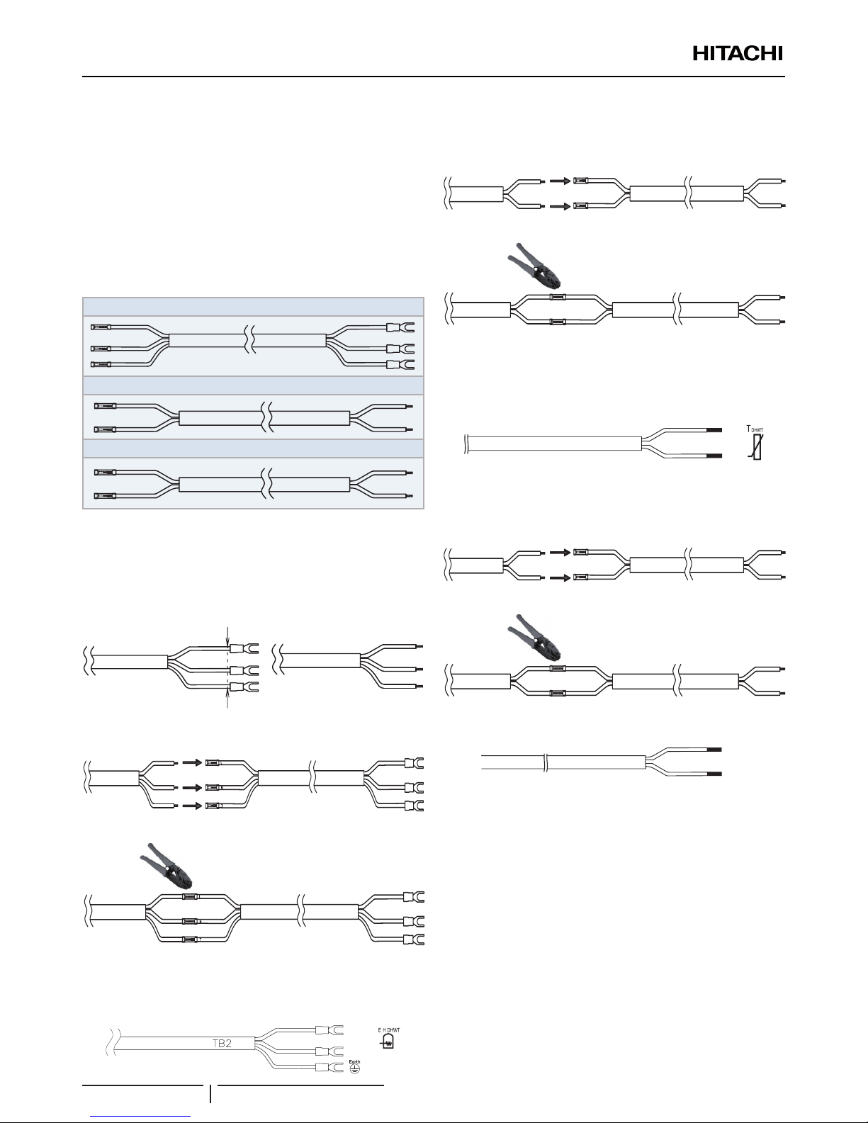
• Cut and strip the free end of the 3 wires of the factory
supplied electric heater cable.
1.1)
1.2)
Connect the extension cable to the factory supplied cable.
(Factory supplied cable)
2.1)
(Extension cable)
(Factory supplied cable)
(Extension cable)
2.2)
(*)
(*): Use a crimping tool to crimp the cables.
• Connect the earth wire to the correct terminal, as shown in
the picture For more information refer to the wiring diagram.
30(N)
31(L)
}
Tank thermistor
• Connect the extension cable to the factory supplied cable.
(Factory supplied cable)
(Extension cable)
1.1)
(Factory supplied cable)
(Extension cable)
1.2)
(*)
(*): Use a crimping tool to crimp the cables.
• Connect the extension cables to the correct terminal, as
shown in the picture. For more information refer to wiring
diagram.
5
6
LCD controller
• Connect the extension cable to the factory supplied cable.
(Factory supplied cable)
(Extension cable)
1.1)
(Factory supplied cable)
(Extension cable)
1.2)
(*)
(*): Use a crimping tool to crimp the cables.
3(A)
4(B)
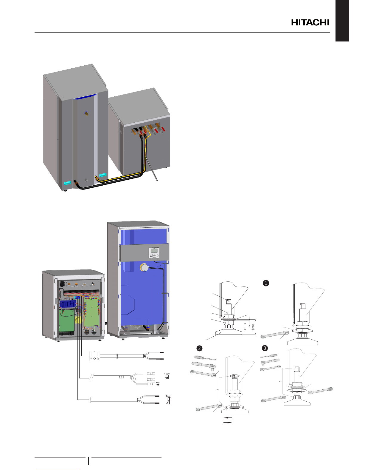
• Take the three cables and drive them through the rear cover
of the tank unit.
INSTALLATION
PMML0344B rev.0 - 04/2016
18
ENGLISH
7 Run the cables together with the exible pipes. Fix them with
plastic bands.
Extension wires
• Connect the extension cables to the correct terminal, as
shown in the picture. For more information refer to wiring
diagram.
30(N)
31(L)
}
Electric heater connection cable
5
6
Thermistor connection cable
3(A)
4(B)
OK
Unit controller connection cable
8 Levelling procedure
Indoor unit
Follow the same procedure explained in Installation of indoor
unit alone (Without tank) on the YUTAKI S80 indoor unit
Installation and operation manual.
Domestic hot water tank
If it is necessary, adjust the height of the mounting foot as
follows:
? NOTE
• All the procedure must be done before lling the water tank.
• Adjust only the necessary mounting foot of the DHW tank with the
foot locknuts and when the tank is in the nal position (moving the
DHWT after levelling can make it uneven again).
• Start with all four feet screwed in as far as possible (factory supplied
position).
• Use two or more people for levelling procedure.
Follow the process:
1 Loosen the locknut of the mounting feet which needs to be
extended (using a wrench).
2 Turn the mounting foot to extend the height (use the
hexagon or slot designed for this purpose in the shaft end).
3 When the mounting foot is in his end position, lock the
locknut. It may be necessary holding the foot to keep it from
turning while tightening the locknut. Use for this purpose the
hexagon or slot in the shaft end.
If it is needed to proceed with the levelling procedure with
a second foot (process 1 to 3), never work over one foot
at same time. When nish, all 4 locknut must be tightened
rmly.
5
8
Foot
Locknut
Weld nut
Washer
Threaded shaft
Hexagon and slot
for help in the
foot adjustment
process
17 mm
Loosen locknut
7mm
10 mm
Adjust the
foot’s height
as needed
(2 options)
Extend
Take in
Hold the foot
shaft to keep
it from turning
(2 options)
Lock the foot
turning the
locknut
INSTALLATION
PMML0344B rev.0 - 04/2016
19
6.3.3 DHW tank xation to the wall
Fix the domestic hot water tank to the wall in order to provide a
higher stability (use the factory supplied accessory intended for
this purpose).
1 Fix the accessory to the DHW tank on the upper cover
through the holes with the bundled factory supplied screws.
? NOTE
Use the accessory slotted hole to x the DHW tank to the wall at the
desired distance.
2 Fix the accessory to the wall with eld supplied screws.
122 mm: minimum distance between
the end of the male tting and the
wall xing hole.
? NOTE
Check that the tank is installed totally vertical.
6.3.4 Test and check
Before assembling the covers, test and check the following
items:
• Water leakage
• Refrigerant leakage
• Electrical connection
• ...
? NOTE
The following documents must be referred:
• Refer to the chapters “4.1.4 Water lling” and “9 COMMISSIONING”
in this document (Tank)
• Refer to the YUTAKI S80 indoor unit Installation and operation
manual, for the information about the refrigerant charge, water lling
and Commissioning of the indoor unit.
• For the specic details about refrigerant charge tasks refer the
Outdoor unit Installation and Operation manual.
! DANGER
DO NOT CONNECT THE POWER SUPPLY TO THE INDOOR UNIT
AND DHW TANK PRIOR TO FILLING BOTH CIRCUITS WITH WATER
AND CHECKING WATER PRESSURE AND THE TOTAL ABSENCE OF
ANY WATER LEAKAGE.
6.3.5 Cover’s assembly
Finally, reassembly all the cover’s removed.
INSTALLATION
PMML0344B rev.0 - 04/2016
20
ENGLISH
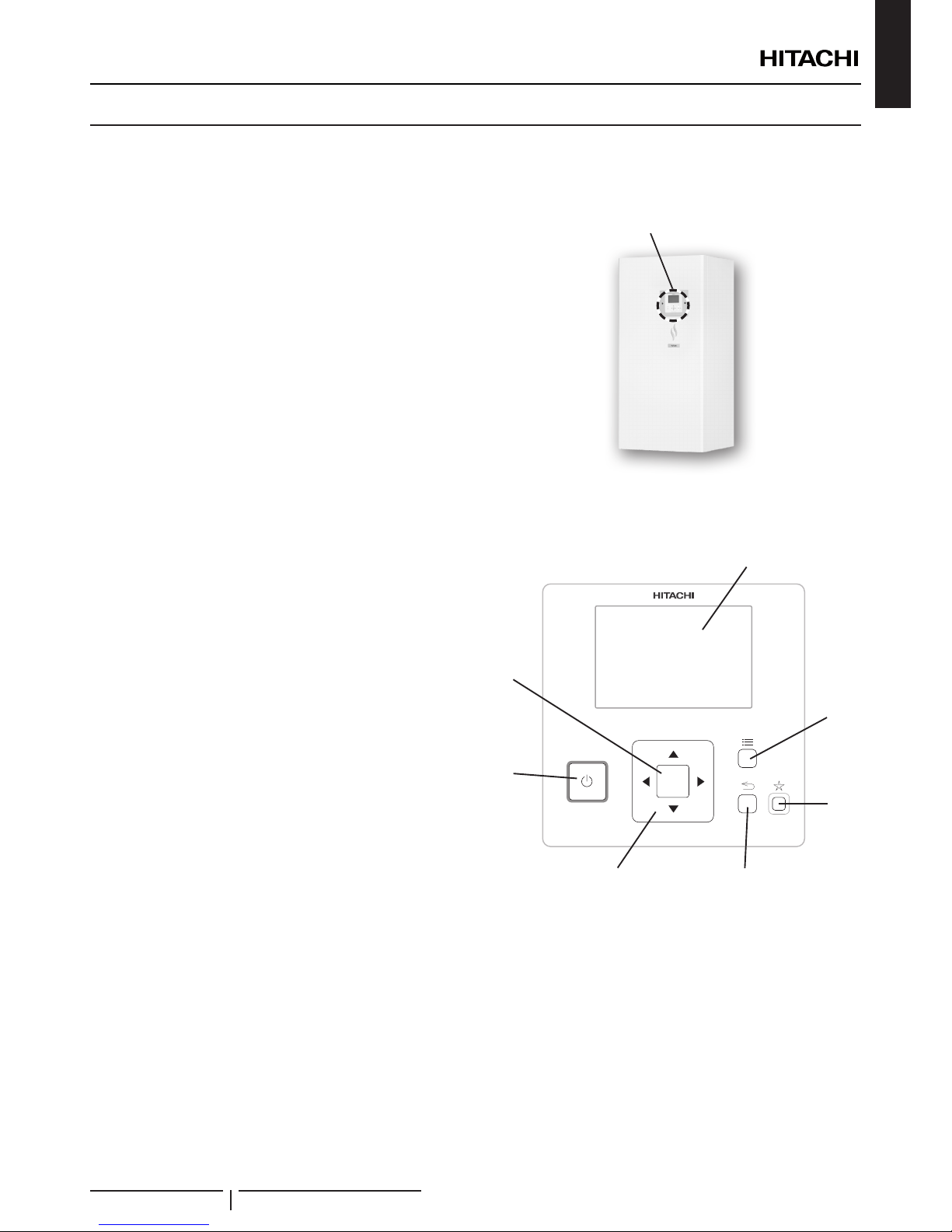
7 DHW TANK OPERATION
Operation switches location
The Unit controller (PC-ARFHE) is integrated into the DHW tank.
Unit controller
PC-ARFHE
The LCD controller working mode is very simple, with 7 buttons that make possible the access to all the display menus, which can
be shown by the LCD liquid crystal display.
Liquid Cristal display
Screen where controller software is displayed.
OK button
To select the variables to be edited and to conrm the selected
values
Arrows key
It helps the user to move through the menus and views
Run/Stop
It works for all zones if none of the zones is selected or only for
one zone when selected.
Menu button
It shows the different conguration options of the user controller.
Return button
To return to the previous screen.
Favourite button
When this button is pressed, the selected favourite action (ECO,
Holidays, simple timer or DHW boost) is directly executed.
OK
DHW TANK OPERATION
PMML0344B rev.0 - 04/2016
21
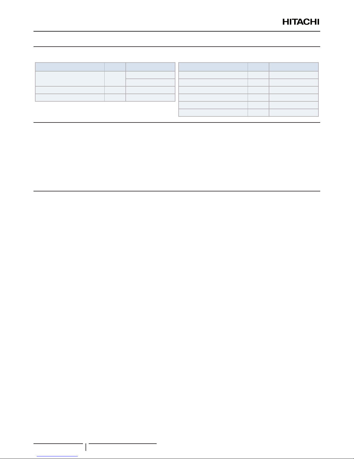
8 CONTROL DEVICE SETTING
Thermostat (manual reset) Units DHW tank
Cut-Out contactors ºC
28~80 ±5ºC
Safety: 90 ±7ºC
Current A 16 (AC1)
Voltage V 250V
Heating resistances Units DHW tank
Power input kW 2.7
Voltage V 230V
Diameter mm 8
Resistances whole xing are nut “G 1 3/4 (brass)
Material - Incoloy 800
Sensor - NTC 20k at 25ºC
9 COMMISSIONING
When installation is complete, perform commissioning according to the following procedure and hand over the system to the
customer. Perform the commissioning of the units methodically, and check that the electrical wiring and the piping are correctly
connected.
? NOTE
Please, refer to YUTAKI S80 Indoor unit Installation and operation manual for the complete information of the commissioning.
9.1 PRELIMINARY CHECK
9.1.1 Checking the unit
• Check external appearance of the unit to look for any
damage due to transportation or installation.
• Check that all the covers are totally closed.
• Check that there is respected the service space
recommended (see “3.2 Service space” in this document
for the tank and the Outdoor and indoor unit Installation and
operation manuals).
• Check that the unit has been correctly installed and that the
mounting foot are correctly adjusted.
9.1.2 Electrical checking
! CAUTION
Do not operate the system until all the check points have been cleared:
• DO NOT CONNECT THE POWER SUPPLY TO THE INDOOR UNIT
AND DHW TANK PRIOR TO FILLING BOTH CIRCUITS WITH
WATER AND CHECKING WATER PRESSURE AND THE TOTAL
ABSENCE OF ANY WATER LEAKAGE.
• Do not touch any electrical components before than three minutes
after turning OFF the main switch
• Check to ensure the electrical wiring of the DHW tank and the indoor
unit are connected as shown in the corresponding chapter.
• Check to ensure the external wiring is correctly xed to avoid problems
with vibrations, noises and cut out wires with the plates.
9.1.3 Hydraulic circuit checking
• Check that the circuit and the tank have been properly
ushed and lled with water and that the installation has
been drained: the pressure of the heating coil circuit must be
1.8 bar (at least 1.5 bar).
• The pressure of the DHW circuit in the tank has to be lower
than 7 bars.
• Check that the water tank heating coil is completely lled.
• Check for any leakage in water cycle. Pay special attention
to the water piping connections.
• Make sure the system’s internal water volume is correct.
• Make sure the DHW tank internal water volume is correct.
• Check that the hydraulic circuit’s valves are fully open.
! CAUTION
• Operating the system with closed valves will damage the unit.
• Check to see that air purge valve is open and that the heating coil
hydraulic circuit is air purged. The installer is responsible of completely
air purging the installation.
• Check that the water pump of the space heating and heating coil
circuits work within the pump operating range and that the water ow
is over the pump’s minimum. If the water ow is under 12 liters/minute
(with ow switch tolerance), alarm will be displayed on the unit.
• Remember that water connection must be accordance with local
regulations.
• Water quality must comply with EU directive 98/83 EC.
CONTROL DEVICE SETTING
PMML0344B rev.0 - 04/2016
22
 Loading...