

Page 1
POWER TOOLS
TECHNICAL DATA
AND
SERVICE MANUAL
HAMMER DRILL
DH 45SA
SPECIFICATIONS AND PARTS ARE SUBJECT TO CHANGE FOR IMPROVEMENT
LIST No. E457 Apr. 2000
D
MODELS
DH 45SA
Page 2

CONTENTS
Page[ Business Section ]
1. PRODUCT NAME
••••••••••••••••••••••••••••••••••••••••••••••••••••••••••••••••••••••••••••••••••••••••••••••••••••••••••••••••••••••••
1
2. MARKETING OBJECTIVE
••••••••••••••••••••••••••••••••••••••••••••••••••••••••••••••••••••••••••••••••••••••••••••••••••••••••••
1
3. APPLICATIONS
••••••••••••••••••••••••••••••••••••••••••••••••••••••••••••••••••••••••••••••••••••••••••••••••••••••••••••••••••••••••••
1
4. SELLING POINTS
•••••••••••••••••••••••••••••••••••••••••••••••••••••••••••••••••••••••••••••••••••••••••••••••••••••••••••••••••••••••
2
4-1. Selling Point Descriptions
•••••••••••••••••••••••••••••••••••••••••••••••••••••••••••••••••••••••••••••••••••••••••••••••••••••••
3
5. SPECIFICATIONS
•••••••••••••••••••••••••••••••••••••••••••••••••••••••••••••••••••••••••••••••••••••••••••••••••••••••••••••••••••••••
4
5-1. Specifications
••••••••••••••••••••••••••••••••••••••••••••••••••••••••••••••••••••••••••••••••••••••••••••••••••••••••••••••••••••••••
4
5-2. Optional Accessories
•••••••••••••••••••••••••••••••••••••••••••••••••••••••••••••••••••••••••••••••••••••••••••••••••••••••••••••
5
6. COMPARISONS WITH SIMILAR PRODUCTS
•••••••••••••••••••••••••••••••••••••• ••••••••••••••••••••••••••••••••••••••
10
6-1. Specification Comparisons
•••••••••••••••••••••••••••••••••••••••••••••••••••••••••••••••••••••••••••••••••••••••••••••••••••••
10
6-2. Drilling Speed Comparison
••••••••••••••••••••••••••••••••••••••••••••••••••••••••••••••••••••••••••••••••••••••••••••••••••••••
11
6-3. Chiseling Performance
•••••••••••••••••••••••••••••••••••••••••••••••••••••••••••••••••••••••••••••••••••••••••••••••••••••••••••
12
7. PRECAUTIONS IN SALES PROMOTION
•••••••••••••••••••••••••••••••••••••••••••••••••••••••••••••••••••••••••••••••••••
13
7-1. Handling Instructions
•••••••••••••••••••••••••••••••••••••••••••••••••••••••••••••••••••••••••••••••••••••••••••••••••••••• •••••••
13
8. REFERENCES
••••••••••••••••••••••••••••••••••••••••••••••••••••••••••••••••••••••••••••••••••••••••••••••••••••••••••••••••••••••••••••
13
8-1. Grease Replacement Procedures
•••••••••••••••••••••••••••••••••••••••••••••••••••••••••••••••••••••••••••••••••••• •••••••
13
8-2. O-Ring Replacement
•••••••••••••••••••••••••••••••••••••••••••••••••••••••••••••••••••••••••••••••••••••••••••••••••••••••••• ••••
13
8-3. Structure of the DH 45SA Hammer Drill
•••••••••••••••••••••••••••••••••••••••••••••••••••••••••••••••••••••••• •••••••••••
14
[ Service Section ]
9. PRECAUTIONS IN DISASSEMBLY AND REASSEMBLY
•••••••••••••••••••••••••••••••••••••••••••••••••••••••••••
19
9-1. Disassembly
••••••••••••••••••••••••••••••••••••••••••••••••••••••••••••••••••••••••••••••••••••••••••••••••••••••••••••••••••••••••••
19
9-2. Reassembly
••••••••••••••••••••••••••••••••••••••••••••••••••••••••••••••••••••••••••••••••••••••••••••••••••••••••••••••••••••••••••
20
9-3. Screw Lock TB 1401
•••••••••••••••••••••••••••••••••••••••••••••••••••••••••••••••••••••••••••••••••••••••••••••••••••••••••••••••
22
9-4. Tightening Torque
•••••••••••••••••••••••••••••••••••••••••••••••••••••••••••••••••••••••••••••••••••••••••••••••••••••••••••••••••••
22
9-5. Wiring Diagrams
•••••••••••••••••••••••••••••••••••••••••••••••••••••••••••••••••••••••••••••••••••••••••••••••••••••••••••••••••••••
23
9-6. Insulation Tests
••••••••••••••••••••••••••••••••••••••••••••••••••••••••••••••••••••••••••••••••••••••••••••••••••••••••••••••••••••••
23
9-7. No-load Current Values
•••••••••••••••••••••••••••••••••••••••••••••••••••••••••••••••••••••••••••••••••••••••••••••••••••••••••••
23
10. STANDARD REPAIR TIME (UNIT) SCHEDULES
••••••••••••••••••••••••••••••••••••••••••••••••••••••••••••••••••••••
24
[ Appendix ]
Assembly Diagram for DH 45SA
•••••••••••••••••••••••••••••••••••••••••••••••••••••••••••••••••••••••••••••••••••••••••••••••••••••
25
Notice for use
Specifications and parts are subject to change for improvement.
Refer to Hitachi Power Tool Technical News for further information.
Page 3

--- 1 ---
1. PRODUCT NAME
Hitachi Hammer Drill, Model DH 45SA
2. MARKETING OBJECTIVE
There are four shank types in the 40 --- 50 mm market.
(1) Hexagon (13 mm ), (2) Hexagon (19 mm-Kango-), (3) SDS max, (4) Spline
The market tendency shows growth of the SDS max shank share, however, the hexagon (13 mm) shank retains
its No. 1 share in many markets because of economical accessory prices and compatibility with customer's
existing tools and accessories. Recently, demand for bigger dia. hole drilling is increasing year by year for
computer cable wiring and anchoring for earthquake-proof reinforcement work.
To meet market demand for a powerful, larger capacity Hammer Drill with hexagon (13 mm) shank, the Model
DH 45SA was developed as an advanced version of Model DH 40SA/YB.
The key features are as follows:
High performance, fast drilling speed: 80 % faster (at maximum) than DH 40SA/YB
Less fatigue, comfortable operation using the soft-grip & shock-absorbing handle
Other features (grease-packed lubrication, ergonomic exterior design)
3. APPLICA TIONS
Concrete drilling
Drilling anchor bolt holes
Crushing, chiseling, grooving, edging, cutting, stripping, compacting/tamping and roughing concrete surfaces
[Applicable examples]
Air conditioning
••••••••••••••••••••••••••••••••
Installation of air conditioners and water coolers
Piping and wiring
•••••••••••••••••••••••••••••
Electric, gas and water supply work
Electric fixtures
•••••••••••••••••••••••••••••••
Installation of electrical and lighting fixtures
Sanitary facilities
••••••••••••••••••••••••••••••
Sanitary plumbing
Interior finishing
•••••••••••••••••••••••••••••••
Installation of seats, display counters, ducts and interior decoration
Other building, construction and repair work
2
1
Page 4
--- 2 ---
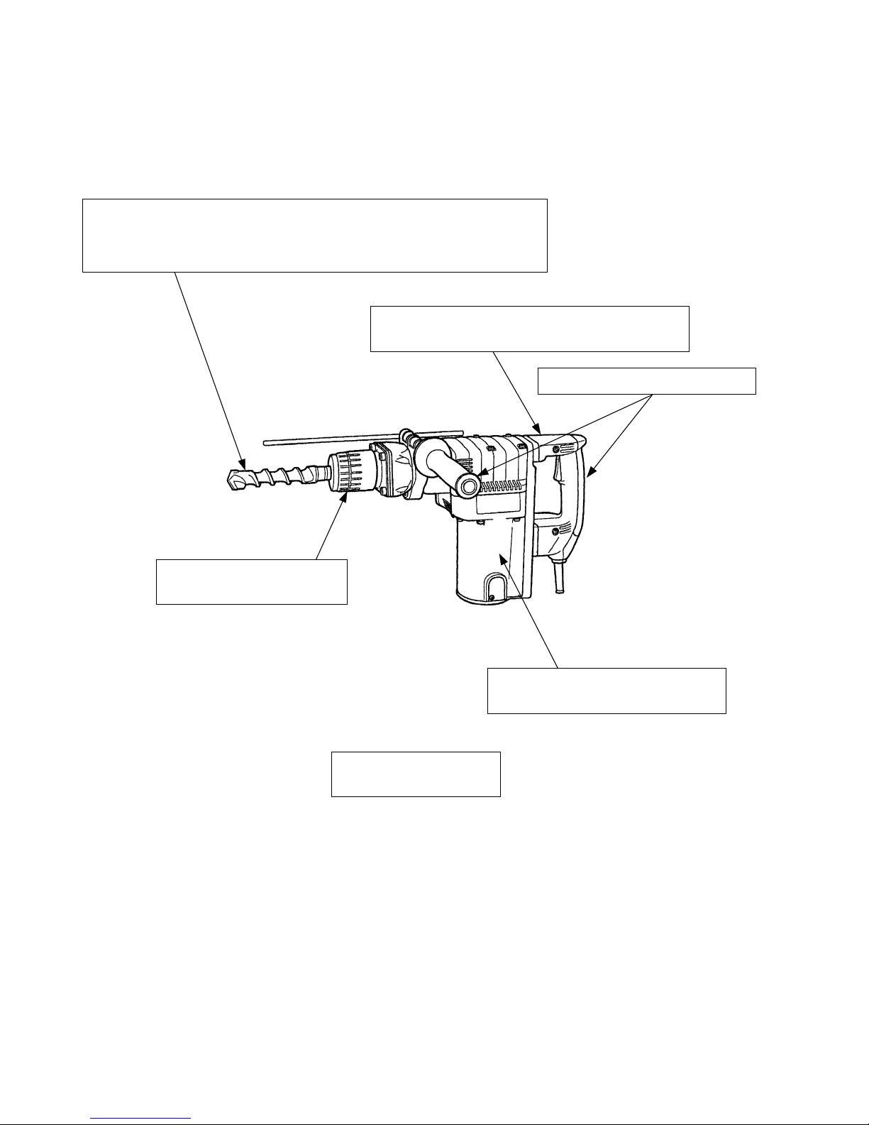
4. SELLING POINTS
Soft-touch handle and side handle
Double-insulation for safer operation
without grounding
Maintenance-free sealed
grease design
Easy-to-use rotary type bit
retainer for quick bit changes
Fig. 1
Vibration-isolating handle provided with
vibration-isolating rubbers reduces operator fatigue
Faster drilling speed and higher efficiency thanks to the powerful motor and
greater striking energy
(About 1.4 times faster than the Model DH 42)
(About 1.8 times faster than the Models DH 40SA/YB)
Page 5
--- 3 ---
4-1. Selling Point Descriptions
4-1-1. Faster drilling speed
The drilling speed is 40 % faster than that of the Model DH 42, as the Model DH 45SA has greater striking energy
owing to the powerful motor and the total optimization of the rotation speed, striking frequency and the weight of
the striker.
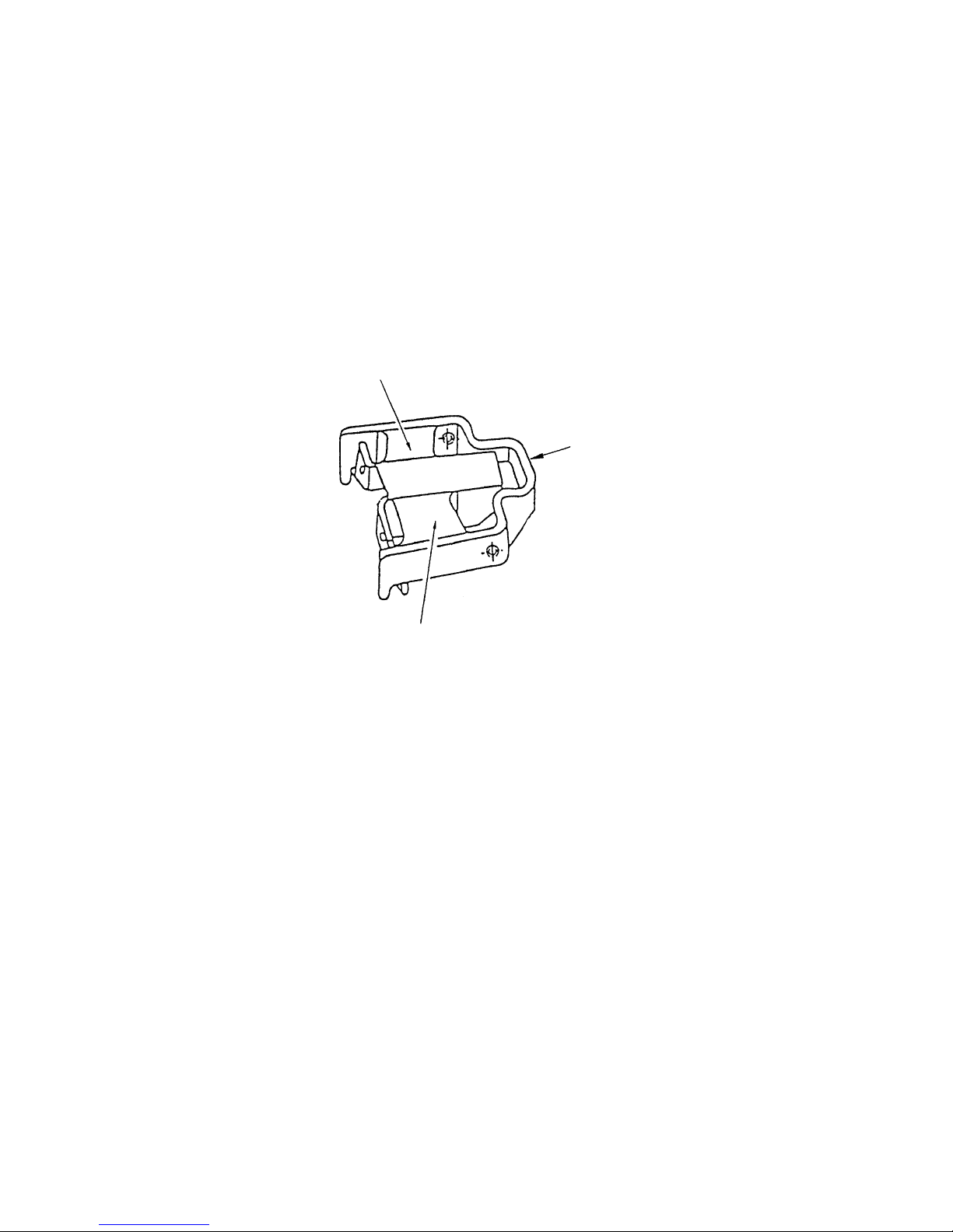
4-1-2. Vibration-isolating handle reduces operator fatigue
The two vibration-isolating rubbers provided between the handle and the crank case, and also between the handle
and the housing efficiently absorb the vibration transmitted from the tool main body to minimize transmission of
vibration to the operator's arms.
4-1-3. Soft-touch handle and side handle
The double-layer molded handle and side handle consist of a plastic resin base covered with a soft plastic layer to
ensure a soft touch and easy grip of the handles.
4-1-4. Easy-to-use tool holder
The easy-to-grip tool holder allows the tool to be attached or removed simply by turning the grip.
4-1-5. Needle-pin type slip clutch
The Model DH 45SA is equipped with a needle-pin type slip clutch to ensure higher accuracy slip torque and
enhanced safety.
Fig. 2
Handle side
Vibration-isolating rubber
Vibration-isolating rubber
Page 6
--- 4 ---
Material
Housing
•••
Glassfiber reinforced polyamide resin (green)
Handle
Handle cover
Crank case cover
•••
Glassfiber reinforced polyamide resin (black, gray)
Type of handle
Drill bit (max. dia.): 45 mm (1-3/4"), core bit (max.dia.): 120 mm (4-3/4")
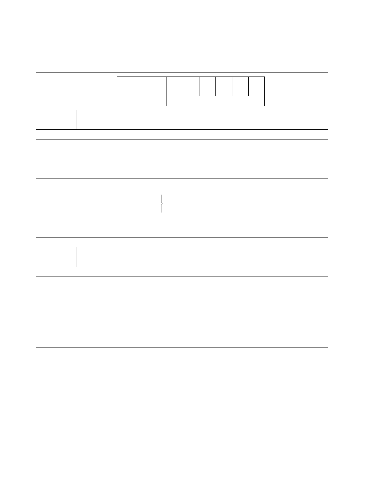
5. SPECIFICATIONS
5-1. Specifications
Capacity
Power source
Voltage, current, input
Type of switch
Enclosure
Dimensions
Weight
Packaging
Standard accessories
Net*
Gross
AC single phase 50 Hz or 60 Hz
300/min.
250/min.
Trigger switch
D-type handle and side handle
10.3 kg (22.7 lbs.)
15.2 kg (33.4 lbs.)
Corrugated cardboard box
Plastic case
••••••••••••••••••••••••••••••••••••••
1
Side handle
•••••••••••••••••••••••••••••••••••••••
1
Hex. bar wrench 5 mm
•••••••••••••••••••••••
1
Hex. bar wrench 6 mm
•••••••••••••••••••••••
1
Hex. bar wrench 8 mm
•••••••••••••••••••••••
1
Stopper
••••••••••••••••••••••••••••••••••••••••••••
1
Grease (A)
••••••••••••••••••••••••••••••••••••••••
1
Dust cap
•••••••••••••••••••••••••••••••••••••••••••
1
Voltage (V)
Current (A)
Input (W)
110 115 127 220 230 240
13.4 12.8 11.6 6.6 6.4 6.2
1400
* Net weight excludes cord and side handle.
Rotation
speed
No-load
Full-load
Type of motor
AC single phase commutator motor
Full-load blow
2,500/min.
Insulation structure
Double insulation
Plastic case color
Off-black green
478 mm x 293 mm x 120 mm (Length x Height x Width)
(18-13/16" x 11-9/16" x 4-3/4")
Page 7

--- 5 ---
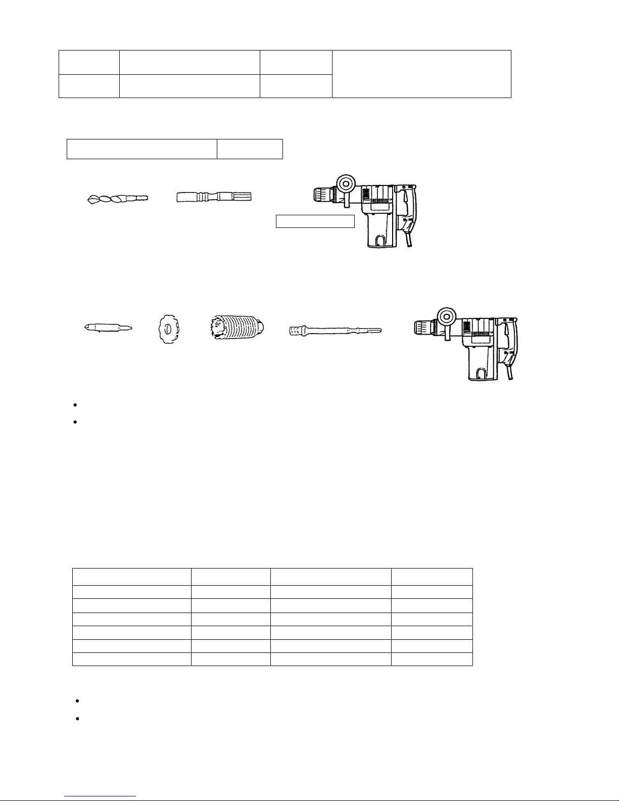
5-2. Optional Accessories
1. Drilling work for through-holes (rotation + striking)
(1) Drill bit (hexagon shaft)
+
+
Code No.
985721
---
985724
--985727
985730
985733
--985736
--985739
313322
280 (11")
Overall length (mm)
Outer diameter (mm)
16 (5/8")
18 (11/16")
19 (3/4")
20 (25/32")
22 (7/8")
25 (31/32")
28 (1-7/64")
30 (1-3/16")
32 (1-1/4")
35 (1-3/8")
38 (1-1/2")
40 (1-9/16")
Code No.
985720
---
985723
--985726
985729
985732
--985735
--985738
---
400 (15-3/4")
Code No.
991330
991331
991332
991333
991335
991336
991337
991338
991339
991340
991341
---
550 (21-5/8")
Code No.
985722
--985725
991334
985728
985731
985734
--985737
--985740
---
505 (19-7/8")
2. Drilling work for anchor holes (rotation + striking)
+
(1) Drill bit (taper shank)
(2) Taper shank adapter
(3) Cotter
(3) Cotter
Outer diameter (mm) Code No.
11 (7/16") 944460
12.3 (15/32") 944461
12.7 (1/2") 993038
14.3 (9/16") 944462
14.5 (9/16") 944500
17.5 (11/16") 944463
21.5 (27/32") 944464
(1) Drill bit (taper shank)
(2) Taper shank adapter
Taper dimension Code No.
Morse taper No.1
Morse taper No.2
985750
985751
944477
Code No.
Page 8
--- 6 ---
Outer diameter (in.)
54 mm (2-1/8")
64 mm (2-17/32")
79 mm (3-1/8")
94 mm (3-11/16")
105 mm (4-1/8")
120 mm (4-3/4")
Code No.
955155
956002
955157
956004
955159
956006
A-taper
B-taper
9.7 mm (3/8") x 1/20 Taper (A) 985754
12.9 mm (1/2") x 1/20 Taper (B) 985755
Taper shank adapters for A-taper or
B-taper shanks are provided as optional
accessories. Taper shank drill bits are
not provided.
For Australia
K-taper shank adapter 992813
+
+
A ratio shank adapter is provided as an optional accessory, but corresponding drill bits are not provided.
(1) Drill bit (ratio shank) (2) Ratio shank adapter Code No. 985761
3. Boring work for large-dia. holes (rotation + striking)
+
+
+
+
(2) Guide plate
Core bits with outer diameter of 32, 35, 38, 45, 54, 64, 79, 105, 120 mm (1-1/4", 1-3/8", 1-1/2", 1-25/32",
2-1/8", 2-17/32", 3-1/8", 3-11/16", 4-1/8", 4-3/4")
[Guide plate is not used with core bits with outer diameter of 25 mm (31/32") and 29 mm (1-5/32")]
(3) Core bit
Outer diameter (in.)
25 mm (31/32")
29 mm (1-5/32")
32 mm (1-1/4")
35 mm (1-3/8")
38 mm (1-1/2")
45 mm (1-25/32")
Code No.
955994
955995
955996
955998
956000
955154
(4) Core bit shank
(1) Center pin
Code No. 956009 for core bits with outer diameter of 32, 35 mm (1-1/4", 1-3/8")
Code No. 955165 for core bits with outer diameter of 38, 45, 54, 64, 79, 94, 105, 120 mm (1-1/2", 1-25/32",
2-1/8", 2-17/32", 3-1/8", 3-11/16", 4-1/8", 4-3/4")
[Center pin is not used with core bits of 25 mm (31/32") and 29 mm (1-5/32")]
Code No. 956008 for core bits with outer diameter of 25, 29, 32 and 35 mm (31/32", 1-5/32", 1-1/4" and 1-3/8")
Code No. 955163 for core bits with outer diameter of 38, 45, 54, 64, 79, 94, 105, 120 mm (1-1/2", 1-25/32",
1-1/8", 1-17/32", 3-11/16", 4-1/8", 4-3/4")
(1) Center pin (2) Guide plate (3) Core bit (4) Core bit shank
Page 9
--- 7 ---
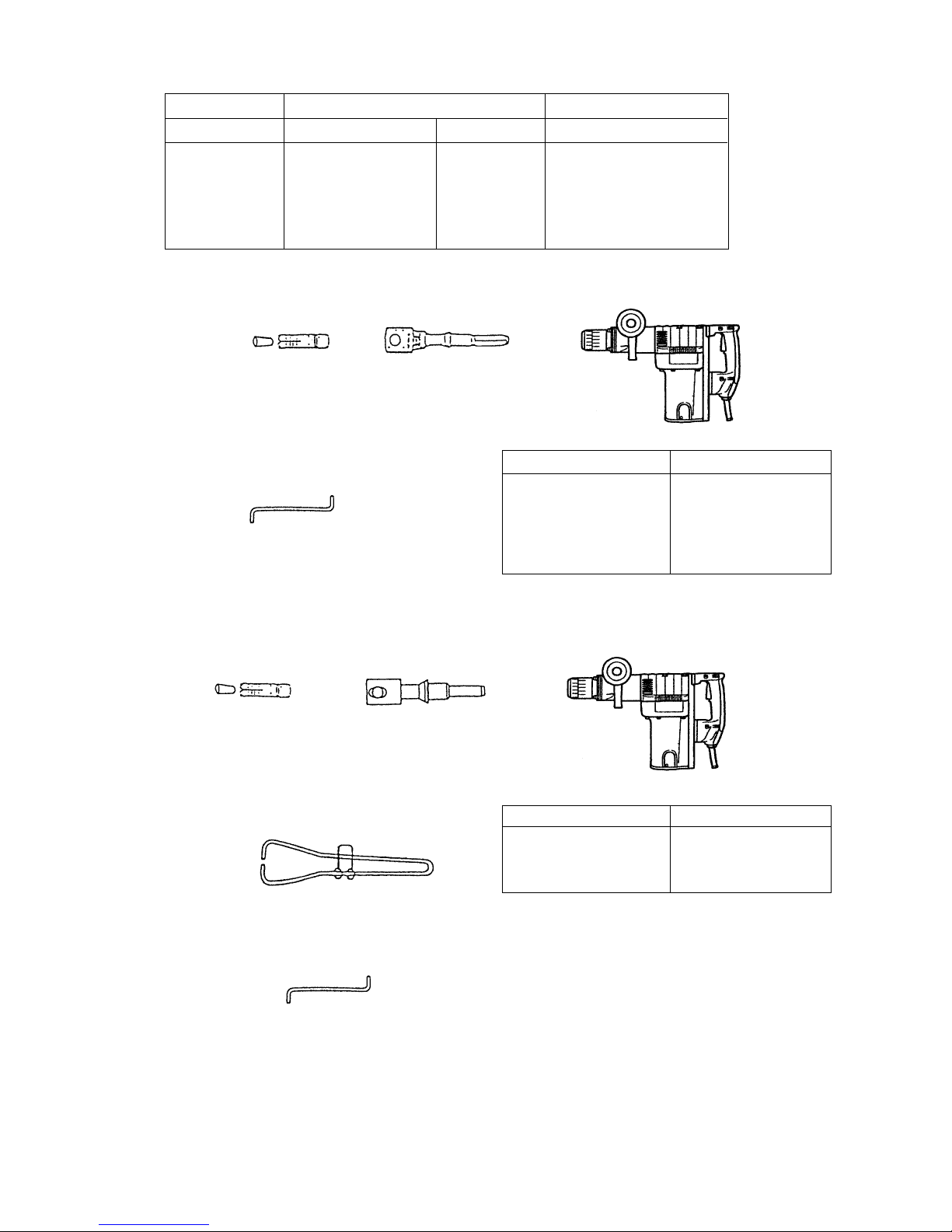
(1) Anchor adapter (for impact)
Anchor size: W3/8 (No. 30), W1/2 (No. 40)
W5/8 (No.50)
(1) Anchor adapter (for rotation + striking)
Anchor size W1/4 (No. 20), W5/16 (No. 25), W3/8 (No. 30),
W1/2 (No. 40), W5/8 (No. 50)
(2) Drift key (Code No. 944574)
5. Anchor work for self-drilling anchors (striking)
(5) Core bit for efficient drilling
Center pin (C)
Core bit (with guide plate)
Core bit shank
Code No.
Code No.
Outer diameter (in.)
Code No.
4. Anchor work for self-drilling anchors (rotation + striking)
65 mm (2-9/16")
80 mm (3-5/32")
90 mm (3-1/2")
100 mm (3-15/16")
105 mm (4-1/8")
992814
992815
992816
992817
992818
903901
992819
+
+
+
W 1/4 (No. 20)
W 5/16 (No. 25)
W 3/8 (No. 30)
W 1/2 (No. 40)
W 5/8 (No. 50)
(1) Anchor size Code No.
985756
985757
985758
985759
985760
+
+
++
W 3/8 (No. 30)
W 1/2 (No. 40)
W 5/8 (No. 50)
(1) Anchor size Code No.
981929
981930
981931
(2) Turning handle (Code No. 944573)
(3) Drift key (Code No. 944574)
Page 10
--- 8 ---
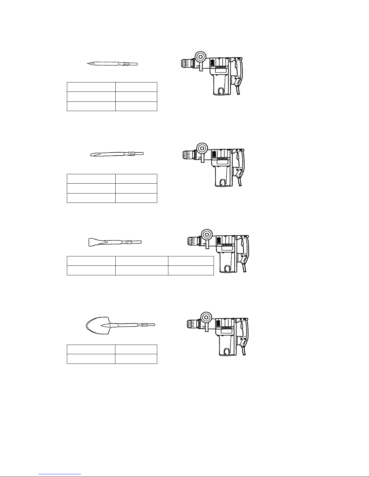
6. Demolition work (striking)
(1) Bull point
Overall length: 280 mm (11"), 450 mm (17-3/4")
280 mm
450 mm
Overall length
Code No.
981922
981923
+
7. Grooving and edging work (striking)
(1) Cold chisel
Overall length: 280 mm (11"), 450 mm (17-3/4")
+
280 mm
450 mm
Overall length
Code No.
981925
981926
8. Cutting and stripping work (asphalt cutting, etc.) (striking)
+
(1) Cutter
9. Digging work (substitute pick-ax) (striking)
280 mm (11")
Overall length
Code No.
98192445 mm (2")
Width
+
(1) Scoop
405 mm (16")
Overall length
Code No.
956126
Page 11

--- 9 ---
10. Roughing surface work (striking)
(1) Bushing tool (2) Shank
++
250 mm (10")
Overall length
Code No.
955186
Code No. 955183
11. Tamping work (striking)
++
(1) Rammer (2) Shank
250 mm (10")
Overall length
Code No.
955186
Code No. 955181
O.D. 140 mm (5-33/64")
12. Syringe (for chip removal)
Code No. 944575
13. Impact drill grease
Code No. 980927
500 g Can
Code No. 308471
70 g Tube
Code No. 981840
30 g Tube
Note: Code numbers listed above are subject to change without notice. Please refer to periodic Technical
News Bulletins for updates.
Page 12

--- 10 ---
Overall length (mm)
6. COMPARISONS WITH SIMILAR PRODUCTS
6-1. Specification Comparisons
Maker
Model
Item
Capacity
Drill bit dia. (mm)
Input (W)
No-load (/min.)
Full-load blow (/min.)
Dimensions
Full-load vibration level (dB)
Insulation structure
Height (mm)
*Weight excludes cord and side handle.
Core bit dia. (mm)
Full-load (/min.)
Rotation
speed
Weight listed on the catalog (kg)*
Actual weight (kg)*
No-load sound pressure level (dB/A)
415 (16-11/32")
255 (10-1/32")
102 (4-1/32")
425 (16-3/4")
252 (9-15/16")
103 (4-1/16")
480 (18-29/32")
260 (10-1/4")
115 (4-17/32")
478 (18-13/16")
293 (11-9/16")
120 (4-3/4")
10.3 (22.7 lbs.) 8 (17.6 lbs.)
6.9 (15.2 lbs.)
8 (17.6 lbs.)
9.8 (21.6 lbs.)
8 (17.6 lbs.)
6.5 (14.3 lbs.)
8 (17.6 lbs.)
2500 3100
2800
2750
Double insulation Single insulation
Double insulation
Double insulation
121 119
118
118
87
88 87
88
1400 1140
950
1150
45 (1-3/4")
120 (4-3/4")
40 (1-9/16")
120 (4-3/4")
40 (1-9/16")
105 (4-1/8")
38 (1-1/2")
120 (4-3/4")
300
250
370
290
360
300
360
260
HIT ACHI
DH 45SA
HIT ACHI
DH 42
HIT ACHI
DH 40SA
C
Width (mm)
Page 13

--- 11 ---
6-2. Drilling Speed Comparison
Drilling speed varies considerably depending on the work conditions. Use the factory test results shown in Fig. 3
as a reference, for comparison purposes only.
Fig.3
[Test conditions]
Posture : Downward drilling
Pressure force : 98 N (10 kgf)
Test material : Concrete panel with a compression strength of 23.5 x 10⁶ N/m2 (240 kgf/cm2)
Drill bit size : 13 mm hexagon shank bit
*: Note that the data marked with asterisk is the test result using a drill bit which is beyond the tool's rated
capacity. Use the above data as a reference, for comparison purposes only.
16
22
25
28
32
38
40
HITACHI
HITACHI
HITACHI
C
HITACHI
HITACHI
HITACHI
C
HITACHI
HITACHI
HITACHI
C
HITACHI
HITACHI
HITACHI
C
HITACHI
HITACHI
HITACHI
C
HITACHI
HITACHI
HITACHI
C
HITACHI
HITACHI
HITACHI
C
DH 45SA
DH 42
DH 40SA
C
DH 45SA
DH 42
DH 40SA
C
DH 45SA
DH 42
DH 40SA
C
DH 45SA
DH 42
DH 40SA
C
DH 45SA
DH 42
DH 40SA
C
DH 45SA
DH 42
DH 40SA
C
DH 45SA
DH 42
DH 40SA
C
Drill bit dia.
(mm)
Maker
Model
Drilling speed (mm/min.)
0
500
400
300
200
100
170
120
170
220
220
150
210
300
260
115
80
60
80
110
80
60
75*
270
240
300
350
240
190
410
410
340
410
540
Page 14

--- 12 ---
[Test conditions]
Posture : Downward chiseling
Test material : Concrete panel with a compression strength of 23.5 x 10⁶ N/m2 (240 kgf/cm2)
Bull point size : Bull point of 280 mm
Fig. 4
6-3. Chiseling Performance
Chiseling performance varies considerably depending on the work conditions. Use these factory test results
shown in Fig. 4 as a reference, for comparison purposes only .
DH 42
DH 45SA
DH 40SA
C
160
100
70
70
50
100
150
0
Voltage
230 V
Chiseling quantity (kg/30 min.)
Chiseling quantity in 30 min.
Page 15

--- 13 ---
7. PRECAUTIONS IN SALES PROMOTION
In the interest of promoting the safest and most efficient use of the Model DH 45SA Hammer Drill by all of our
customers, it is very important that at the time of sale the salesperson carefully ensures that the buyer seriously
recognizes the importance of the contents of the Handling Instructions, and fully understands the meaning of the
precautions listed on the Caution Plate attached to each tool.
7-1. Handling Instructions
Although every effort is made in each step of design, manufacture and inspection to provide protection against
safety hazards, the dangers inherent in the use of any electric tool cannot be completely eliminated. Accordingly,
general precautions and suggestions for the use of electric power tools, and specific precautions and suggestions
for the use of the Hammer Drill are listed in the Handling Instructions to enhance the safe, efficient use of the tool
by the customer. Salespersons must be thoroughly familiar with the contents of the Handling Instructions to be
able to offer appropriate guidance to the customer during sales promotion.
8. REFERENCES
8-1. Grease Replacement Procedures
The electro-pneumatic hammering section and gear change section each use different kinds of grease. It is not
necessary to replenish the grease unless the tool is disassembled for repair or there is grease leakage due to a
damaged seal.
A special grease is used for the hammering section. To change the grease in the hammering section (cylinder
case and crank case), carefully wipe the old grease off the parts, and re-lube with 30 g in the cylinder case and
75 g in the crank case (on the connecting rod side). Take care not to overfill with grease as an excessive amount
of grease can cause hammering failure.
The gear change section (in the gear cover) uses grease No. 29 for power tools. Apply 40 g to the gear cover and
the gear portion in the crank case, and 20 g between the washer (A) of the slip clutch and the crank case. Do not
use the special grease used for the hammering section, or it will leak to the motor parts resulting in failure of the
tool.
8-2. O-Ring Replacement
The O-ring (attached to the striker and piston) plays an important role to ensure air tightness. Despite its
prolonged service life due to a special rubber material, it will inevitably wear out. Early replacement, preferably
once every six months, is recommended.
Page 16

--- 14 ---
8-3. Structure of the DH 45SA Hammer Drill
Cylinder
Key
Striker
Air chamber
Bevel
gear
Piston
Connecting rod
Crank shaft
First gear
Second hammer
Spline connection
O-ring
Second gear
Bevel pinion
Armature
Fig. 5
Rotation transmission
Rotation transmission is described with reference to Fig. 5. The gear arrangement of the DH 45SA has the
armature shaft positioned between the crank shaft and the bevel pinion shaft. Rotation of the armature shaft is
transmitted to the second gear through the first gear of the crank shaft and the second pinion. Then the
rotation is transmitted from the second gear through the slip mechanism disposed between the second gear
and the bevel pinion shaft to turn the bevel gear. The latter is keyed to the cylinder to rotate together. Cylinder
rotation is transmitted through the spline connection to the second hammer. Rotation is then transmitted to the
drill bit which is fitted into the hexagonal hole of the second hammer.
Hammering action
Armature rotation is transmitted to the crank and the connecting rod to reciprocally move the piston within the
cylinder. Air pressure developed between the piston and the striker changes as the piston moves. This causes
the striker to continuously hit the end face of the second hammer. Since the striker is moved under air
pressure, a certain air cushioning effect absorbs the striking shock.
If there is any leakage from the air chamber, the air cushioning effect becomes insufficient, resulting in an
incomplete shock absorbing effect. This is why the O-rings (attached to the striker and piston) for air tightness
are so important.
Second pinion
Page 17

--- 15 ---
Needle pin
Spring (C)
Key
Gear holder
Elongated
groove of the
gear holder
Arrangement against idle hammering
The DH 45SA is provided with an arrangement against idle hammering similar to that of the previous
DH 40SA. When the drill bit or bull point is moved off the concrete material, the second hammer is shifted
forward as indicated in Fig. 6 to change the striking position of the striker. This causes the air hole to open so
that air pressure within the air chamber no longer changes even with movement of the piston, bringing the
hammering action to a stop.
Air chamber
Second hammer
Striker
Air hole
Travel distance of the second
hammer and the striker
Fig. 6
Slip mechanism
The slip mechanism structure is described below with reference to Fig. 7. The bevel pinion and the gear holder
are coupled together by the key and press-fitting. Spring (C) and needle pins are housed in elongated grooves
of the gear holder. The needle pin is pressed against the inner face of the second gear by spring (C) to allow
idle rotation of the second gear relative to the gear holder. When an excess torque is exerted on the bevel
pinion shaft, the needle pin is raised upon the projection of the second gear against the load of spring (C) to
allow idle rotation of the second gear. With this arrangement, the clutch slips when a violent torque is applied
to the tool as with the drill bit contacting steel wire within the concrete, protecting the operator from jerking or
being violently thrown around.
Fig. 7
Gear holder
Bevel pinion
Second gear
Cross section A - A
Page 18

--- 16 ---
T ool holder
The tool holder is described below with reference to Fig. 8. As shown, three saddle keys are received in the
three respective elongated holes equidistantly located at the front cover. The cross sectional view A-A
illustrates the mode in which an end attachment tool is held in position. With the grip turned in direction A, the
saddle keys are shifted out of the holes to unlock the attachment tool from the tool body.
When fitting the attachment tool, turn the grip fully in the A direction, insert the tool shank deeply until it hits
against the hole end. Then, turning the grip fully in B direction causes the attachment tool to be securely held
in position. In contrast to the previous knob-retaining structure, the DH 45SA uses three saddle keys locked by
turning the grip, which are able to securely hold the tool with a minimized deflection of the drill bit or other
attachment tool.
Tool
Section A - A
Grip
Front cover
Saddle key
Saddle key holder
A
B
Front cover
Tool
Saddle key
Grip
Saddle key holder
Fig. 8
Page 19

--- 17 ---
Wiring connections
The wiring connections are shown in Fig. 9. The Model DH 45SA adopts a plug-in module type wiring system
consisting of plug (A) ass'y and plug (B) ass'y. The plug (A) ass'y connected with the internal wires of the
stator is fitted into the housing. The plug (B) ass'y is fitted into the handle section through the plug holder and
is connected with the switch terminal and cord. Wiring connection is completed when the housing section, the
handle and handle cover section are all assembled and then fastened together with screws. With such a
wiring structure, assembling and disassembling procedures associated with wiring connection have been
largely simplified over previous models.
Housing
Cord clip
Vinyl tube
Plug (A)
ass'y
Cord
Side cover ass'y
Handle cover
Internal wire
of stator
Plug holder
Handle
Switch
Plug (B) ass'y
Plug (A)
ass'y
Plug (B)
ass'y
Plug
holder
Handle
Handle
cover
Internal wire
of stator
Fig. 9
Page 20

--- 18 ---
Handle and side handle
The double-layer handle structure consists of a plastic base reinforced with glass fiber and an outer layer of
soft resin molded together with the base.
The side handle consists of a steel nut in the base and a hard plastic and a soft resin outer cover molded
together to form the handle. The DH 45SA thus uses the newly designed soft-touch handle and side handle
for easier handling of the tool.
Fluid-tight, dust-proof structure
The crank case and cylinder case are tightly sealed with three O-rings, an oil seal and a rubber seal as
indicated in Fig. 10. This prevents grease from leaking from inside as well as dust particles from getting inside
the tool.
The tool holder is also protected from dust with a rubber front cap and a dust cover.
Fig. 10
Tool holder
Oil seal
Gear cover
O-ring
O-ring (C)
Dust cover
Front cap
Rubber seal
Crank case cover
Crank case
O-ring
Cylinder caseFront cover
Page 21

--- 19 ---
9. PRECAUTIONS IN DISASSEMBLY AND REASSEMBLY
The [Bold] numbers in the descriptions below correspond to the item numbers in the parts list and exploded
assembly diagram.
9-1. Disassembly
(1) Piston and striker
Remove the four Nylock Bolts (W/Flange) M5 x 16 [33] at the Crank Case Cover Ass'y [35] , and remove the
latter. Remove the four Nylock Bolt (W/Flange) M6 x 35 [61] at the Cylinder Case [60] and pull the cylinder
case out of the Crank Case [37]. Remove the Retaining Ring for D12 Shaft [41] and remove the Connecting
Rod Ass'y [70] from the Crank Shaft [42]. Pull out the Piston Pin [72] and remove the Piston [69].
Pull out the Striker [67] by hammering the cylinder case with a plastic hammer. If it is difficult to pull out the
striker, push the removed piston together with the connecting rod ass'y into the Cylinder [65] and quickly pull
them out, and the striker will jump out together with the piston.
(2) Gear in the crank case
Remove the Retaining Ring for D17 Shaft [49] and the Thrust Washer [48] from the Crank Shaft [42]. Pull out
the First Gear [47] with a bearing puller. Remove the Feather Key 5 x 5 x 15 [31]. Remove the Slip Clutch
Ass'y [30] by hammering the end surface of the Crank Case [37] from the Gear Cover [52] side with a plastic
hammer. Remove the two Nylock Hex. Socket Hd. Bolts M5 x 16 [40] from the Bearing Cover [45] and pull out
the Crank Shaft [42] from the gear cover side.
Fig. 11
The slip clutch ass'y can be removed in the following
procedure. First pull out the Ball Bearing 629VVC2PS2L
[29] with a bearing puller, support Washer (A) [23] on a
sleeve as shown in Fig. 11 and release the Bevel Pinion
[19] from the press-fitting by pushing it from the Spacer
[28] side using a hand press. When removing the Gear
Holder [24] from the Second Gear [27], it is recommended
to keep them inside a plastic bag during disassembly to
prevent Springs (C) [25] and Needle Pins D6 x 6 [26] from
scattering.
(3) Tool holder
Remove the Front Cap [1] from Front Washer (A) [3] and
remove the Retaining Ring D35 [2]. Then, Front Washer
(A) [3], Damper Ring [4], Grip [5], Saddle Key Holder [7],
Retainer Spring [8] and three Saddle Keys [6] can be
removed. Remove the Dust Cover [13] from the Front
Cover [14] using the spring hook J-201 (Code No. 970977).
Fig. 12
Sleeve
Spring hook J-201
(Code No. 970977)
[19] Bevel Pinion
[23] Washer (A)
217
R2
[28] Spacer
Page 22

--- 20 ---
9-2. Reassembly
Perform reassembly generally in reverse order of disassembly , following the precautions given below.
(1) Lubrication
Apply special grease (for hammer and hammer drill) to the following portions.
Inner circumference of the Connecting Rod Ass'y [70]
O-Ring (FPM710) [68] attached to the Striker [67] and the Piston [69]
Inner lip portion of the Oil Seal (FPM707) [77]
Fill 75 g of special grease in the Crank Case [37] of the connecting rod side and 30 g in the cylinder case.
Apply power tool grease No. 29 to the following portions.
Needle Bearing (M661) [51]
Armature pinion
Fill 40 g of power tool grease No. 29 in the gear section of the gear cover and the crank case, and 20 g
between the slip clutch (washer (A) side) and the crank case.
(2) Oil seal and others
Handle with care not to damage the Rubber Seal [36] of the crank case, O-Rings (FPM 710) [68] in the piston
and the striker, Oil Seal (FPM 707) [77] in the Gear Cover [52], O-Ring (D) [62] in the cylinder case, O-Ring
[17] in the second hammer and the O-Ring (1AS-60) [16] in the Front Cover [14].
(3) Slip clutch ass'y
Press-fit the Ball Bearing 6202DDCMPS2L [21] to the Bevel Pinion [19] and insert the Washer [22] and then
Washer (A) [23] to the bevel pinion. After mounting the Feather Key 3 x 3 x 8 [20] in the bevel pinion, press-fit
the Gear Holder [24] to the bevel pinion. Then, apply power tool grease No. 29 to the inner circumference of
the Second Gear [27] and mount it on the outer circumference of the gear holder. Place the Needle Pin D6 x 6
[26] without inclination as shown in Fig. 13, then press in Spring (C) [25]. Then press-fit the Spacer [28] and
then Ball Bearing 629VVC2PS2L [29] to the bevel pinion.
B-taper
Fig. 13
[27] Second Gear
[26] Needle Pin D6 x 6
[27] Second Gear
[24] Gear Holder
[19] Bevel Pinion
[25] Spring (C)
A
[24] Gear Holder
A
Section A- A
Page 23

--- 21 ---
[6] Saddle Key
[5] Grip
Alignment mark
3-mm
dia.
hole
[7] Saddle
Key Holder
[8] Retainer
Spring
3-mm dia. side hole
Bent portions
[14] Front Cover
Claw
Claw
(4) Tool holder
Insert the bent portion of the Retainer Spring [8] into the 3-mm dia. side hole of the Front Cover [14]. Apply
power tool grease No.29 to the three slots of the front cover and insert the three Saddle Keys [6] into the slots
each. Insert the other bent portion of the retainer spring into the 3-mm dia. hole of the Saddle Key Holder [7]
and mount the Grip [5] to the saddle key holder aligning the alignment mark as shown below. Turn the grip
about 60˚ clockwise, viewing from the tip, and push it in. The claws of the front cover are then engaged with
the claws of the saddle key holder and the tool holder is in a tool secured status. Hold the grip securely to
prevent the grip from moving upward. Mount the Damper Ring [4] and then Front Washer (A) [3] to the front
cover. Mount the Retaining Ring D35 [2] to the front cover and then mount the Front Cap [1] to Front Washer
(A) [3] to complete reassembly. Check that the tool holder turns smoothly and the mark on the grip is always
positioned in the place shown in "Tool-secured status" below.
Fig. 14
(Viewed from the tip)
Tool-inserted status
Tool-secured status
Alignment mark position
on the grip when a tool is
inserted
Claw of the saddle
key holder
Claw of the front
cover
Alignment mark position on
the grip when a tool is
secured
Turn about 60˚.
[14] Front Cover
[6] Saddle Key
[2] Retaining Ring D35
[4] Damper Ring
[8] Retainer
Spring
[5] Grip
[3] Front Washer (A)
[1] Front Cap
[13] Dust Cover
[7] Saddle Key Holder
Page 24

--- 22 ---
(5) Carbon brush inspection
The motor employs auto-stop carbon brushes. When the carbon brushes near their wear limit, the current to
the motor is automatically interrupted and the motor stops. At that time, replace both carbon brushes with new
ones which have the same carbon brush number "74" as shown in Fig. 15. In addition, always keep the carbon
brushes clean and ensure that they slide freely within the brush holders.
9-3. Screw Lock TB 1401
Apply thread lock compound to all the M5 hexagon socket head bolts (except for M8 for front cover mounting and
M6 hexagon socket head bolts for cylinder case mounting, which are special bolts to be treated as service parts).
(Note) Be sure to apply thread lock compound to the threads during reassembly, as the bolts loosened with
vibrations may cause damage to the tool body .
Fig. 15
9-4. Tightening T orque
M5 hexagon socket head bolt
•••••••••••••••••••••••••••••••••••••••••
7.9 N•m (80 kgf•cm, 69.4 in-lbs.)
D4 tapping screw
•••••••••••••••••••••••••••••••••••••••••••••••••••••••••••
2.0 0.5 N•m (20 5 kgf•cm, 17.4 4.3 in-lbs.)
D5 tapping screw
•••••••••••••••••••••••••••••••••••••••••••••••••••••••••••
2.9 0.5 N•m (30 5 kgf•cm, 26.0 4.3 in-lbs.)
Side cover mounting bolt
••••••••••••••••••••••••••••••••••••••••••••••••
3.9 0.5 N•m (40 5 kgf•cm, 34.7 4.3 in-lbs.)
(Nylock bolt (W/Flange) M5 x 16)
Crank case cover mounting bolt
•••••••••••••••••••••••••••••••••••••
4.9 1.0 N•m (50 10 kgf•cm, 43.4 8.7 in-lbs.)
(Nylock bolt (W/Flange) M5 x 16)
Housing mounting bolt
•••••••••••••••••••••••••••••••••••••••••••••••••• •••
4.9 N•m (50 kgf•cm, 43.4 in-lbs.)
(Nylock bolt (W/Flange) M6 x 40)
Front cover mounting bolt
••••••••••••••••••••••••••••••••••••••••••••••••
29.4 N•m (300 kgf•cm, 260 in-lbs.)
(Nylock High Tension Bolt M8 x 30)
Cylinder case mounting bolt
•••••••••••••••••••••••••••••••••••••••••••••
9.8 N•m (100 kgf•cm, 86.8 in-lbs.)
(Nylock bolt (W/Flange) M6 x 35)
+
2.0
0
+
17.4
0
+
20
0
+
2.0
0
+
20
0
+
17.4
0
+
1.0
0
+
10
0
+
17.4
0
+
8.7
0
+
20
0
+
2.0
0
Wear limit
Number of carbon brush
("74" denotes the last two digits of the code number.)
74
7 mm
17 mm
Page 25

--- 23 ---
9-5. Wiring Diagrams
For products without noise suppressor
Stator
Switch
Connector
Armature
Fig. 16
9-6. Insulation Tests
On completion of disassembly and repair, measure the insulation resistance and dielectric strength.
Insulation resistance: 7 MΩ or more with DC 500 V Megohm Tester
Dielectric strength : AC 4,000 V/1 minute, with no abnormalities
••••••••
220 V --- 240 V
AC 2,500 V/1 minute, with no abnormalities
••••••••
110 V --- 127 V
9-7. No-load Current Values
After no-load operation for 30 minutes, the no-load current values should be as follows.
Plug
Noise
suppressor
Plug
Pillar terminal
Stator
Switch
Armature
For products with noise suppressor
240 V230 V220 V127 V
5.9 A 3.4 A 3.3 A 3.2 A
Voltage
Current (A) Max.
6.8 A 6.5 A
115 V110 V
Page 26

--- 24 ---
10. STANDARD REPAIR TIME (UNIT) SCHEDULES
MODEL 10 20 30 40
Fixed
Variable
DH 45SA
Work Flow
Front Cap
Grip
Saddle Key x 3
Retainer Spring
Saddle Key
Holder
Front Cover
O-Ring x 2
Front Washer
Urethane Ring
Ball Bearing
(6008CM)
Damper
Damper Holder
Urethane Ring
Holder
Front Damper
Damper (B)
Damper Washer
Second Hammer
Handle
Plug (A)
Plug (B)
Side Cover
Ass'y
Armature
Ass'y
Ball Bearing
(6203VV)
Dust Washer
Oil Seal
Sleeve (B)
Handle Cover
Switch (C)
Cord
Cord Armor
60 min.
50
Crank Shaft
Feather Key
(5x5x15)
Ball Bearing
(6205)
Bearing Cover
First Gear
Second Pinion
Housing Ass'y
Stator Ass'y
Seal Packing
Gear Cover
Needle Bearing
Connecting
Rod Ass'y
Needle Bearing
Piston
Piston Pin
Striker
O-Ring
Ball Bearing
(6202)
Washer (A)
Gear Holder
Spring (C)
Needle Pin
Second Gear
Spacer
Ball Bearing
(629VV)
Crank Case
Cylinder
O-Ring (D)
Feather Key
(3x3x20)
Cylinder Case
Needle Bearing
Bevel Gear
Bevel Pinion
Feather Key
(3x3x8)
Crank Case
Cover Ass'y
Rubber Seal
Tail Cover
Ball Bearing
(6201VV)
General Assembly
Page 27

--- 25 ---
Assembly Diagram for DH 45SA
Page 28

--- 26 ---
: ALTERNATIVE PARTS
*
1 318-758 FRONT CAP 1
2 318-757 RETAINING RING D35 1
3 318-756 FRONT WASHER (A) 1
4 318-755 DAMPER RING 1
5 318-754 GRIP 1
6 313-069 SADDLE KEY 3
7 318-752 SADDLE KEY HOLDER 1
8 318-753 RETAINER SPRING 1
9 306-437 NYLOCK HEX. SOCKET HD. BOLT M8X30 4
10 986-892 COLLAR 4
11 319-075 FRONT WASHER 1
12 319-074 FRONT DAMPER 1
13 318-759 DUST COVER 1
14 318-751 FRONT COVER 1
15 318-762 DAMPER (B) 1
16 956-996 O-RING (1AS-60) 1
17 986-882 O-RING 1
18 318-743 SECOND HAMMER 1
19 318-551 BEVEL PINION 1
20 944-109 FEATHER KEY 3X3X8 1
21 620-2DD BALL BEARING 6202DDCMPS2L 1
22 313-058 WASHER 1
23 318-552 WASHER (A) 1
24 318-554 GEAR HOLDER 1
25 318-555 SPRING (C) 8
26 313-057 NEEDLE PIN D6X6 8
27 318-553 SECOND GEAR 1
28 318-556 SPACER 1
29 629-VVM BALL BEARING 629VVC2PS2L 1
30 318-550 SLIP CLUTCH ASS'Y 1 INCLUD.19-29
31 945-072 FEATHER KEY 5X5X15 2
32 944-525 BEARING WASHER (C) 1
33 313-082 NYLOCK BOLT (W/FLANGE) M5X16 6
34 991-711 DISTANCE PIECE (B) 4
35 318-584 CRANK CASE COVER ASS'Y 1 INCLUD.34
36 313-084 RUBBER SEAL 1
37 318-543 CRANK CASE 1
38 980-750 GUIDE PLATE 2
39 980-727 HANDLE RUBBER 2
40 878-181 NYLOCK HEX. SOCKET HD. BOLT M5X16 8
41 939-542 RETAINING RING FOR D12 SHAFT (10 PCS.) 1
42 318-544 CRANK SHAFT 1
43 620-5DD BALL BEARING 6205DDCMPS2L 1
44 965-469 RETAINING RING FOR D25 SHAFT 1
45 318-548 BEARING COVER 1
46 318-545 SECOND PINION 1
47 318-546 FIRST GEAR 1
48 318-547 THRUST WASHER 1
49 967-261 RETAINING RING FOR D17 SHAFT 1
50 318-549 SEAL PACKING 1
51 939-299 NEEDLE BEARING (M661) 1
3
---
00
PARTS
DH 45SA
ITEM
NO.
CODE NO. DESCRIPTION
NO.
USED
REMARKS
Page 29

--- 27 ---
: ALTERNATIVE PARTS
DH 45SA
PARTS
ITEM
No.
CODE NO. DESCRIPTION
NO.
USED
REMARKS
52 318-595 GEAR COVER 1
53 993-235 DAMPER WASHER 1
54 318-745 DAMPER 1
55 318-746 DAMPER HOLDER 1
56 318-748 URETHANE RING 1
57 318-747 URETHANE RING HOLDER 1
58 318-582 RETAINING RING D40 1
59 600-8CM BALL BEARING 6008CM 1
60 318-749 CYLINDER CASE 1
61 318-451 NYLOCK BOLT (W/FLANGE) M6X35 4
62 985-779 O-RING (D) 1
63 985-782 NEEDLE BEARING (M526320) 1
64 318-741 BEVEL GEAR 1
65 318-740 CYLINDER 1
66 971-750 FEATHER KEY 3X3X20 2
67 318-742 STRIKER 1
68 318-917 O-RING (FPM 710) 2
69 985-772 PISTON 1
70 318-557 CONNECTING ROD ASS'Y 1 INCLUD.71
71 980-756 NEEDLE BEARING (NSK AJ50 1203) 1
72 955-593 PISTON PIN 1
73 318-574 SIDE HANDLE 1
74 318-575 HANDLE HOLDER 1
75 318-576 HANDLE BOLT 1
76 971-786 STOPPER ROD 1
77 318-596 OIL SEAL (FPM 707) 1
78 620-3VV BALL BEARING 6203VVCMPS2L 1
79 318-597 SLEEVE (B) 1
80 318-594 DUST WASHER 1
81 318-918 FAN 1
* 82 360-526C ARMATURE ASS'Y 110V-115V 1 INCLUD.81
* 82 360-526D ARMATURE ASS'Y 127V 1 INCLUD.81
* 82 360-526E ARMATURE ASS'Y 220V-230V 1 INCLUD.81
* 82 360-526F ARMATURE ASS'Y 240V 1 INCLUD.81
83 318-633 FAN GUIDE 1
84 953-121 HEX. HD. TAPPING SCREW D5X50 2
* 85 340-467C STATOR ASS'Y 110V-115V 1 INCLUD.86
* 85 340-467D STATOR ASS'Y 127V 1 INCLUD.86
* 85 340-467E STATOR ASS'Y 220V-230V 1 INCLUD.86
* 85 340-467F STATOR ASS'Y 240V 1 INCLUD.86
86 958-032 BRUSH TERMINAL 2
87 318-764 HOUSING ASS'Y 1 INCLUD.94,95
88 HITACHI LABEL 1
89 318-570 NYLOCK BOLT (W/FLANGE) M6X40 6
90 307-811
TAPPING SCREW (W/FLANGE) D4X16 (BLACK)
2
91 318-599 BRUSH CAP COVER 2
92 940-540 BRUSH CAP 2
93 999-074
CARBON BRUSH (AUTO STOP TYPE) (1 PAIR)
2
94 980-487 BRUSH HOLDER 2
95 938-477 HEX. SOCKET SET SCREW M5X8 2
96 NAME PLATE 1
3
---
00
*
Page 30

--- 28 ---
PARTS
DH 45SA
: ALTERNATIVE PARTS
ITEM
No.
CODE NO. DESCRIPTION
NO.
USED
REMARKS
97 305-558
TAPPING SCREW (W/FLANGE) D5X25 (BLACK)
4
98 944-954 BEARING WASHER 1
99 620-1VV BALL BEARING 6201VVCMPS2L 1
100 318-598 TAIL COVER 1
101 303-273 TAPPING SCREW (W/FLANGE) D5X16 3
102 318-750 SIDE COVER ASS'Y 1 INCLUD.103,109
103 318-572 HANDLE PACKING (A) 1
104 991-711 DISTANCE PIECE (B) 4
105 318-601 HANDLE 1
106 313-093 SWITCH (C) (2P SCREW TYPE W/O LOCK) 1
107 318-602 HANDLE COVER 1
108 301-653
TAPPING SCREW (W/FLANGE) D4X20 (BLACK)
2
109 318-573 HANDLE PACKING (B) 1
* 110 958-049 CORD ARMOR D8.2 1
* 110 940-778 CORD ARMOR D10.7 1
* 111 992-810 TERMINAL 1 FOR GBR(230V)
* 111 980-063 TERMINAL 1 FOR SAF,AUS
* 112 960-266 CORD CLIP 1
* 112 981-987Z CORD CLIP 1 FOR SUI
113 984-750 TAPPING SCREW (W/FLANGE) D4X16 2
* 114 500-390Z CORD 1 (CORD ARMOR D10.7)
* 114 500-394Z CORD 1 (CORD ARMOR D10.7) FOR SYR
* 114 500-454Z CORD 1 (CORD ARMOR D10.7) FOR SAF
* 114 500-408Z CORD 1 (CORD ARMOR D8.2) FOR AUS
* 114 500-460Z CORD 1 (CORD ARMOR D10.7) FOR GBR(110V)
* 114 500-446Z CORD 1 (CORD ARMOR D10.7) FOR GBR(230V)
* 114 500-391Z CORD 1 (CORD ARMOR D10.7) FOR SUI
* 115 313-142 PLUG (A) 1 FOR AUS,SAF,EUROPE
* 115 313-092 PLUG (A) 1
* 116 959-141 CONNECTOR 50092 (10 PCS.) 1 FOR TPE,ECU,SUR,THA,SRI,INA,CHN,SYR,
SIN,KUW,NGU,AUS
* 117 318-648 PLUG (B) 1
* 117 318-600 PLUG (B) 1 FOR AUS
118 938-307 PILLAR TERMINAL 1
119 318-603 PLUG HOLDER 1
*
3
---
00
STANDARD ACCESSORIES
ITEM
No.
CODE NO. DESCRIPTION
NO.
USED
REMARKS
501 318-646 CASE (PLASTIC) 1
502 981-840
GREASE (A) FOR HAMMER.HAMMER DRILL (30G)
1
503 944-458 HEX. BAR WRENCH 4MM 1
504 944-459 HEX. BAR WRENCH 5MM 1
505 872-422 HEX. BAR WRENCH 6MM 1
506 315-871 DUST CAP 1
* 507 992-813 K-TAPER SHANK ADAPTER 1 FOR AUS
* 508 944-477 COTTER 1 FOR AUS
Page 31

--- 29 ---
: ALTERNATIVE PARTS
*
OPTIONAL ACCESSORIES
ITEM
No.
CODE NO. DESCRIPTION
NO.
USED
REMARKS
3
---
00
DH 45SA
601 985-721 DRILL BIT D16.0X280 (HEX. SHANK TYPE) 1
602 985-720 DRILL BIT D16.0X400 (HEX. SHANK TYPE) 1
603 985-722 DRILL BIT D16.0X505 (HEX. SHANK TYPE) 1
604 991-330 DRILL BIT D16.0X550 (HEX. SHANK TYPE) 1
605 991-331 DRILL BIT D18.0X550 (HEX. SHANK TYPE) 1
606 985-724 DRILL BIT D19.0X280 (HEX. SHANK TYPE) 1
607 985-723 DRILL BIT D19.0X400 (HEX. SHANK TYPE) 1
608 985-725 DRILL BIT D19.0X505 (HEX. SHANK TYPE) 1
609 991-332 DRILL BIT D19.0X550 (HEX. SHANK TYPE) 1
610 991-334 DRILL BIT D20.0X505 (HEX. SHANK TYPE) 1
611 991-333 DRILL BIT D20.0X550 (HEX. SHANK TYPE) 1
612 985-727 DRILL BIT D22.0X280 (HEX. SHANK TYPE) 1
613 985-726 DRILL BIT D22.0X400 (HEX. SHANK TYPE) 1
614 985-728 DRILL BIT D22.0X505 (HEX. SHANK TYPE) 1
615 991-335 DRILL BIT D22.0X550 (HEX. SHANK TYPE) 1
616 985-730 DRILL BIT D25.0X280 (HEX. SHANK TYPE) 1
617 985-729 DRILL BIT D25.0X400 (HEX. SHANK TYPE) 1
618 985-731 DRILL BIT D25.0X505 (HEX. SHANK TYPE) 1
619 991-336 DRILL BIT D25.0X550 (HEX. SHANK TYPE) 1
620 985-733 DRILL BIT D28.0X280 (HEX. SHANK TYPE) 1
621 985-732 DRILL BIT D28.0X400 (HEX. SHANK TYPE) 1
622 985-734 DRILL BIT D28.0X505 (HEX. SHANK TYPE) 1
623 991-337 DRILL BIT D28.0X550 (HEX. SHANK TYPE) 1
624 991-338 DRILL BIT D30.0X550 (HEX. SHANK TYPE) 1
625 985-736 DRILL BIT D32.0X280 (HEX. SHANK TYPE) 1
626 985-735 DRILL BIT D32.0X400 (HEX. SHANK TYPE) 1
627 985-737 DRILL BIT D32.0X505 (HEX. SHANK TYPE) 1
628 991-339 DRILL BIT D32.0X550 (HEX. SHANK TYPE) 1
629 991-340 DRILL BIT D35.0X550 (HEX. SHANK TYPE) 1
630 985-739 DRILL BIT D38.0X280 (HEX. SHANK TYPE) 1
631 985-738 DRILL BIT D38.0X400 (HEX. SHANK TYPE) 1
632 985-740 DRILL BIT D38.0X505 (HEX. SHANK TYPE) 1
633 991-341 DRILL BIT D38.0X550 (HEX. SHANK TYPE) 1
634 944-460 TAPER SHANK DRILL BIT D11X100 1
635 944-461 TAPER SHANK DRILL BIT D12.3X110 1
636 993-038 TAPER SHANK DRILL BIT D12.7X110 1
637 944-462 TAPER SHANK DRILL BIT D14.3X110 1
638 944-500 TAPER SHANK DRILL BIT D14.5X110 1
639 944-463 TAPER SHANK DRILL BIT D17.5X120 1
640 944-464 TAPER SHANK DRILL BIT D21.5X140 1
641 985-752 TAPER SHANK ADAPTER NO.1 1 INCLUD.643
642 985-753 TAPER SHANK ADAPTER NO.2 1 INCLUD.643
643 944-477 COTTER 1
644 985-754 A-TAPER SHANK ADAPTER (D11.0-17.5) 1
645 985-755 B-TAPER SHANK ADAPTER (D21.5) 1
646 992-813 K-TAPER SHANK ADAPTER 1
647 985-750 DRILL ADAPTER NO.1 (D11.0-17.5) 1
648 985-751 DRILL ADAPTER NO.2 (D21.5) 1
649 955-994 CORE BIT 25MM 1
650 955-995 CORE BIT 29MM 1
651 955-996 CORE BIT 32MM 1 INCLUD.652
Page 32

--- 30 ---
OPTIONAL ACCESSORIES
DH 45SA
ITEM
No.
CODE NO. DESCRIPTION
NO.
USED
REMARKS
652 955-997 GUIDE PLATE (FOR CORE BIT 32MM) 1
653 955-998 CORE BIT 35MM 1 INCLUD.654
654 955-999 GUIDE PLATE (FOR CORE BIT 35MM) 1
655 956-000 CORE BIT 38MM 1 INCLUD.656
656 956-001 GUIDE PLATE (FOR CORE BIT 38MM) 1
657 955-154 CORE BIT 45MM 1 INCLUD.658
658 955-166 GUIDE PLATE (FOR CORE BIT 45MM) 1
659 955-155 CORE BIT 54MM 1 INCLUD.660
660 955-167 GUIDE PLATE (FOR CORE BIT 54MM) 1
661 956-002 CORE BIT 64MM 1 INCLUD.662
662 956-003 GUIDE PLATE (FOR CORE BIT 64MM) 1
663 955-157 CORE BIT 79MM 1 INCLUD.664
664 955-168 GUIDE PLATE (FOR CORE BIT 79MM) 1
665 956-004 CORE BIT 94MM 1 INCLUD.666
666 956-005 GUIDE PLATE (FOR CORE BIT 94MM) 1
667 955-159 CORE BIT 105MM 1 INCLUD.668
668 955-169 GUIDE PLATE (FOR CORE BIT 105MM) 1
669 956-008 CORE BIT SHANK (B) 300L (FOR D25-35) 1 ROUND SHAFT TYPE
670 955-163 CORE BIT SHANK (A) 300L (FOR D38-120) 1
671 956-009 CENTER PIN (B) 147L FOR CORE BIT D32-35 1
672 955-165
CENTER PIN (A) 133L FOR CORE BIT D38-150
1
673 992-814 CORE BIT 65MM 1
674 992-815 CORE BIT 80MM 1
675 992-816 CORE BIT 90MM 1
676 992-817 CORE BIT 100MM 1
677 992-818 CORE BIT 105MM 1
678 992-819 CORE BIT SHANK (C) 1
679 903-901 CENTER PIN (C) 1
680 985-756
ANCHOR ADAPTER NO.20 W1/4"(FOR ROTATION)
1
681 985-757
ANCHOR ADAPTER NO.25 W5/16"(FOR ROTATION)
1
682 985-758
ANCHOR ADAPTER NO.30 W3/8"(FOR ROTATION)
1
683 985-759
ANCHOR ADAPTER NO.40 W1/2"(FOR ROTATION)
1
684 985-760
ANCHOR ADAPTER NO.50 W5/8"(FOR ROTATION)
1
685 981-929 ANCHOR ADAPTER NO.30 1
686 981-930 ANCHOR ADAPTER NO.40 1
687 981-931 ANCHOR ADAPTER NO.50 1
688 985-761 RATIO SHANK ADAPTER 1
689 944-574 DRIFT KEY 1
690 981-922 BULL POINT 280MM (ROUND SHANK TYPE) 1
691 981-923 BULL POINT 450MM (ROUND SHANK TYPE) 1
692 981-925
COLD CHISEL 280MM (ROUND SHANK TYPE)
1
693 981-926
COLD CHISEL 450MM (ROUND SHANK TYPE)
1
694 981-924 CUTTER W45X280L (ROUND SHANK TYPE) 1
695 956-126 SCOOP 405L (ROUND SHANK TYPE) 1
696 955-181 RAMMER 140MM 1
697 955-183 BUSHING TOOL 1
698 955-186
SHANK 250L (FOR RAMMER AND BUSHING TOOL)
1
699 944-575 SYRINGE 1
700 318-085 SYRINGE (BELLOWS TYPE) 1
701 308-471
GREASE FOR HAMMER.HAMMER DRILL (70G)
1
702 980-927
GREASE FOR HAMMER.HAMMER DRILL (500G)
1
3
---
00
Printed in Japan
(000331 N)
 Loading...