

Page 1
PRODUCT NAME
Hitachi Rotary Hammer
Model DH 40MC
CONFIDENTIAL
LIST No.
DH 40MC: F440
Dec. 2016
D
CONTENTS
REPAIR GUIDE -----------------------------------------------------------------------------------------------------------------1
1. Precautions on disassembly and reassembly ------------------------------------------------------------1
• Disassembly ----------------------------------------------------------------------------------------------------1
• Reassembly -----------------------------------------------------------------------------------------------------4
• Lubrication points and types of lubricant -----------------------------------------------------------------8
• Tightening torque ----------------------------------------------------------------------------------------------9
• Insulation test ---------------------------------------------------------------------------------------------------9
• No-load current value -----------------------------------------------------------------------------------------9
• Connecting diagram ---------------------------------------------------------------------------------------- 10
STANDARD REPAIR TIME (UNIT) SCHEDULES ------------------------------------------------------------------- 11
Page
Overseas Sales Division
Page 2
REPAIR GUIDE
1. Precautions on disassembly and reassembly
WARNING: Be sure to disconnect the power cord plug from the wall outlet before conducting
repair. Otherwise, the motor may run suddenly and you could get injured.
[Bold] numbers in the description below correspond to the item numbers in the parts list and exploded
assembly diagram for the Model DH 40MC.
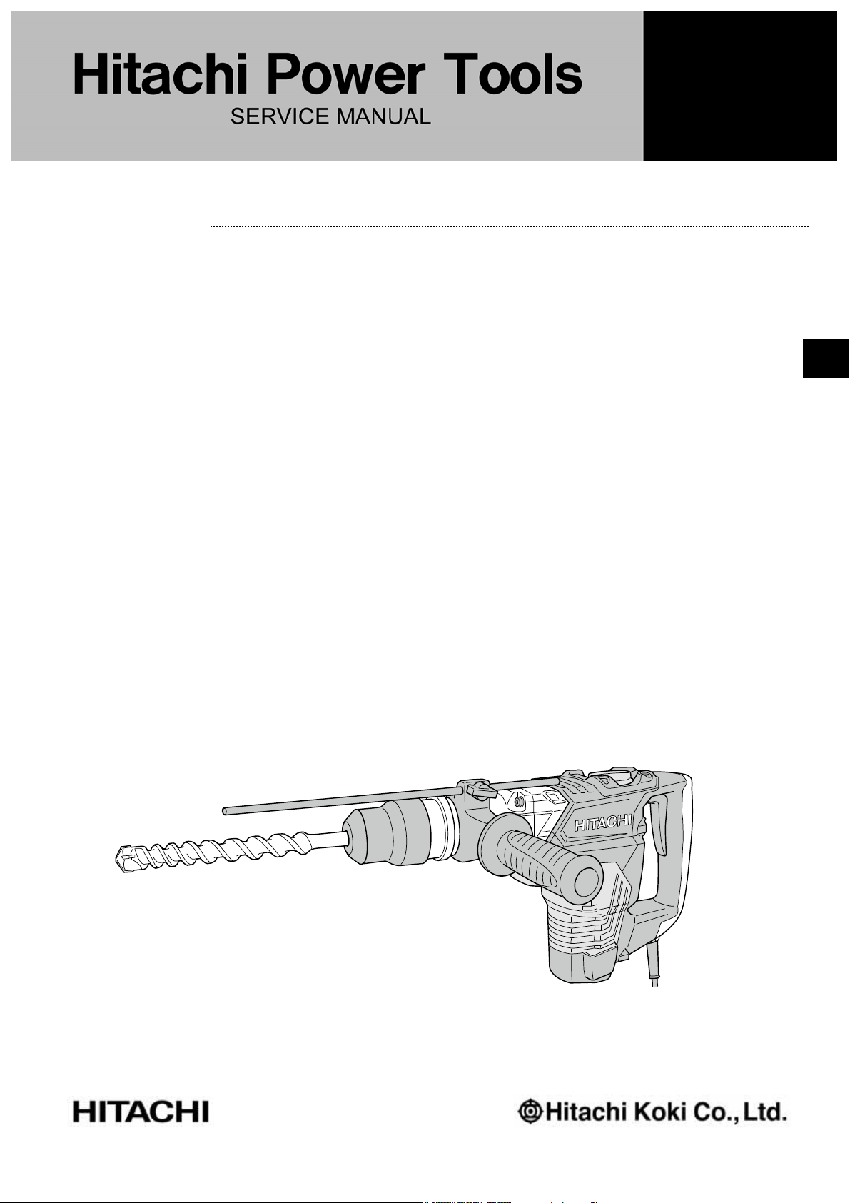
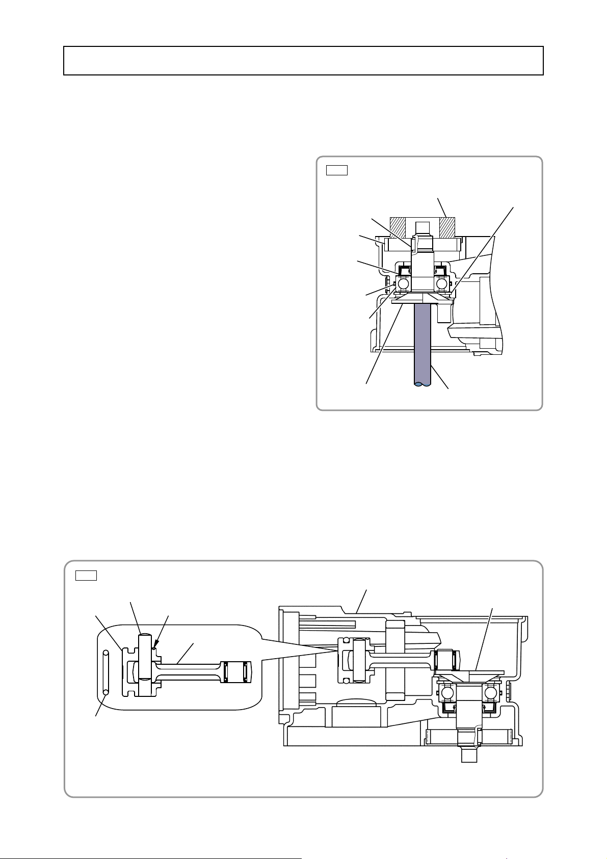
1. Disassembly of the tool retainer
• Forcibly pull out the Front Cap [1] from the Retainer Sleeve [28] while pulling the Grip [11] in the arrow
direction as shown in Fig. 1.
• Remove the Stopper Ring [2] by using a retainer ring puller. Then the Grip [11], Retainer Washer [3],
Retainer Damper (A) [4], Bit Lock Holder [12], two Bit Locks [27], Thrust Plate [13], Retainer Spring [14]
and Spring Holder (A) [15] can be removed from the Retainer Sleeve [28] (Fig. 2).
Fig. 1
[1]
[11]
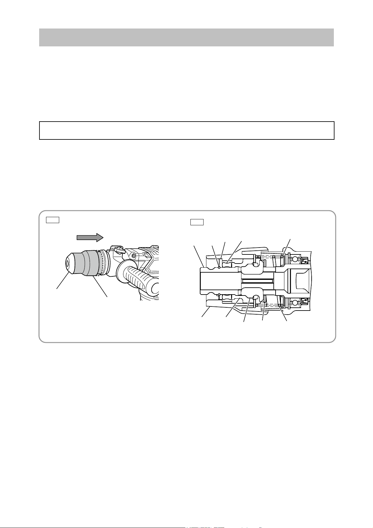
2. Disassembly of the hammering mechanism
(1) Removing the second hammer and striker
• Remove the Hex. Socket Hd. Bolt M6 x 25 [21] to remove the Cylinder Case [22], Spring Holder (B)
[37], Retainer Sleeve [28] and other parts from the main body.
• Remove the Second Hammer [30] from the Retainer Sleeve [28] together with the Damper Holder [33],
Damper [32] and Damper Washer [31].
• Pull out the Cylinder [36] from the main body together with the Lock Spring [38], Lock Sleeve [39],
Clutch Spring [40] and Clutch [41].
• Remove the Striker [34] by tapping the end surface of the Cylinder [36] with a plastic hammer.
Disassembly
Fig. 2
[28]
[2]
[11]
[12]
[3]
[4]
[27]
[13]
[15]
[14]
-1-
Page 3
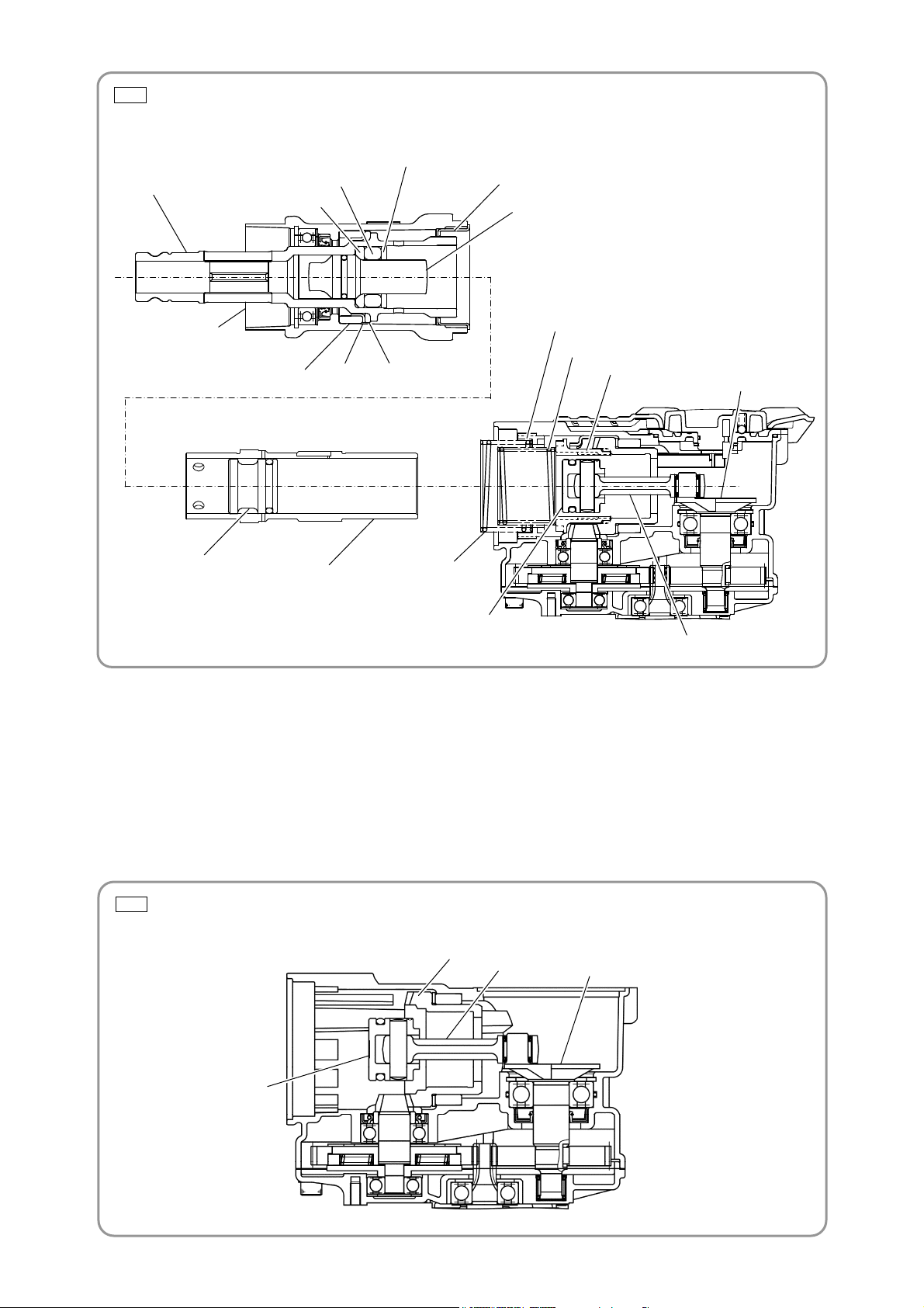
Fig. 3 • Removing the second hammer and striker
[28]
[32]
[31]
[33]
[37]
[30]
[22]
[24]
[25]
[26]
[39]
[40]
[41]
[85]
[34]
[36]
[38]
[47]
[48]
(2) Removing the piston ass’y
• Remove the Hex. Socket Hd. Bolt M5 [110] from the Crank Cover [111]. Detach the Crank Cover [111]
and the assembly of the Lever Shaft Holder [116] from the Crank Case Ass'y [91].
• Remove the Change Plate [119] from the Crank Case Ass'y [91].
• The piston ass’y can be removed from the main body without removing the Bevel Gear [43] and Slip
Clutch Ass’y [93]. Move the Connecting Rod [48] as shown below to remove the piston ass’y from the
Crank Shaft [85].
Fig. 4 • Removing the piston ass’y
[43]
[48]
[85]
Piston ass’y
-2-
Page 4
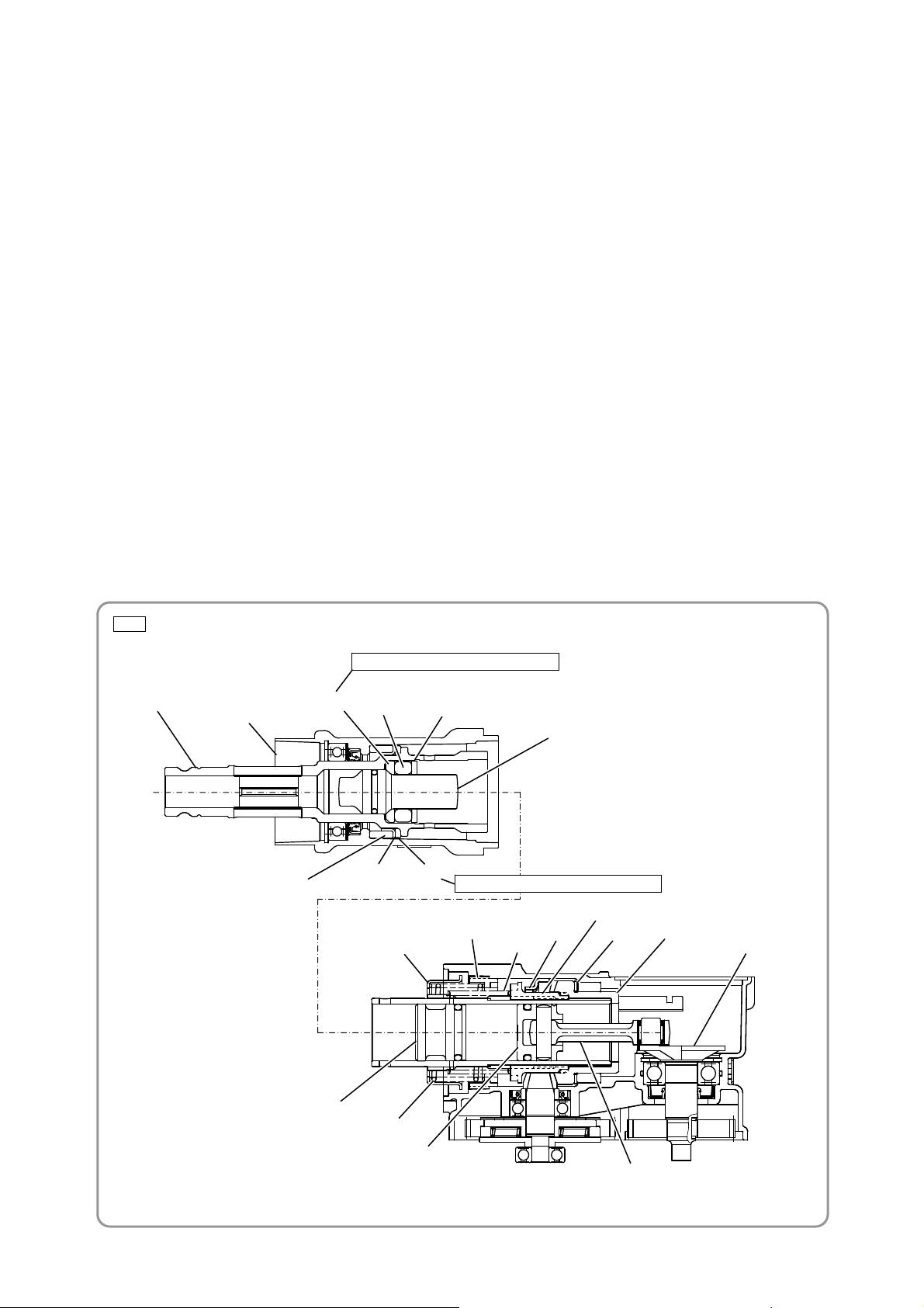
(3) Removing the first gear and crank shaft
• Remove the Hood [126] from the Crank Case Ass'y [91] by removing the Hex. Socket Hd. Bolt M5 x 12
[127] from the Hood [126].
• Remove the Seal Lock Hex. Socket Hd. Bolt M6 x 20 [109], Seal Lock Hex. Socket Hd. Bolt M6 x 45
[92], Hex. Socket Hd. Bolt M5 x 16 [75] and Tapping Screw D5 x 20 [65].
• Separate the Crank Case Ass'y [91] from the Housing Ass'y [55], Handle [76], and Gear Cover [108].
• Remove the Slip Clutch Ass'y [93] from the Crank Case Ass'y [91].
NOTE: Remove the Slip Clutch Ass'y [93] from the Crank Case Ass'y [91] beforehand because
the Bevel Gear [43] cannot be removed if the Slip Clutch Ass'y [93] remains in the Crank
Case Ass'y [91].
• Remove grease from the Piston [47] side and First Gear [123] side of the Crank Case Ass'y [91].
• Use a retaining ring puller to remove the Retaining Ring for D40 Hole [87] fixing the Ball Bearing
6203DD [88].
NOTE: At this time, turn the Crank Shaft [85] to expose the hole of the Retaining Ring for D40
Hole [87] prior to removal.
• Use a hand press to press the end face of the Crank Shaft [85], and then remove the First Gear [123]
and Crank Shaft [85] from the Crank Case Ass'y [91] as shown in Fig. 5.
Fig. 5 • Removing the first gear and crank shaft
[91]
[85]
Hand press
[91]
[123]
[88]
Release the Retaining
Ring for D40 Hole [101]
from the groove.
[85]
[87]
Adequate cradle
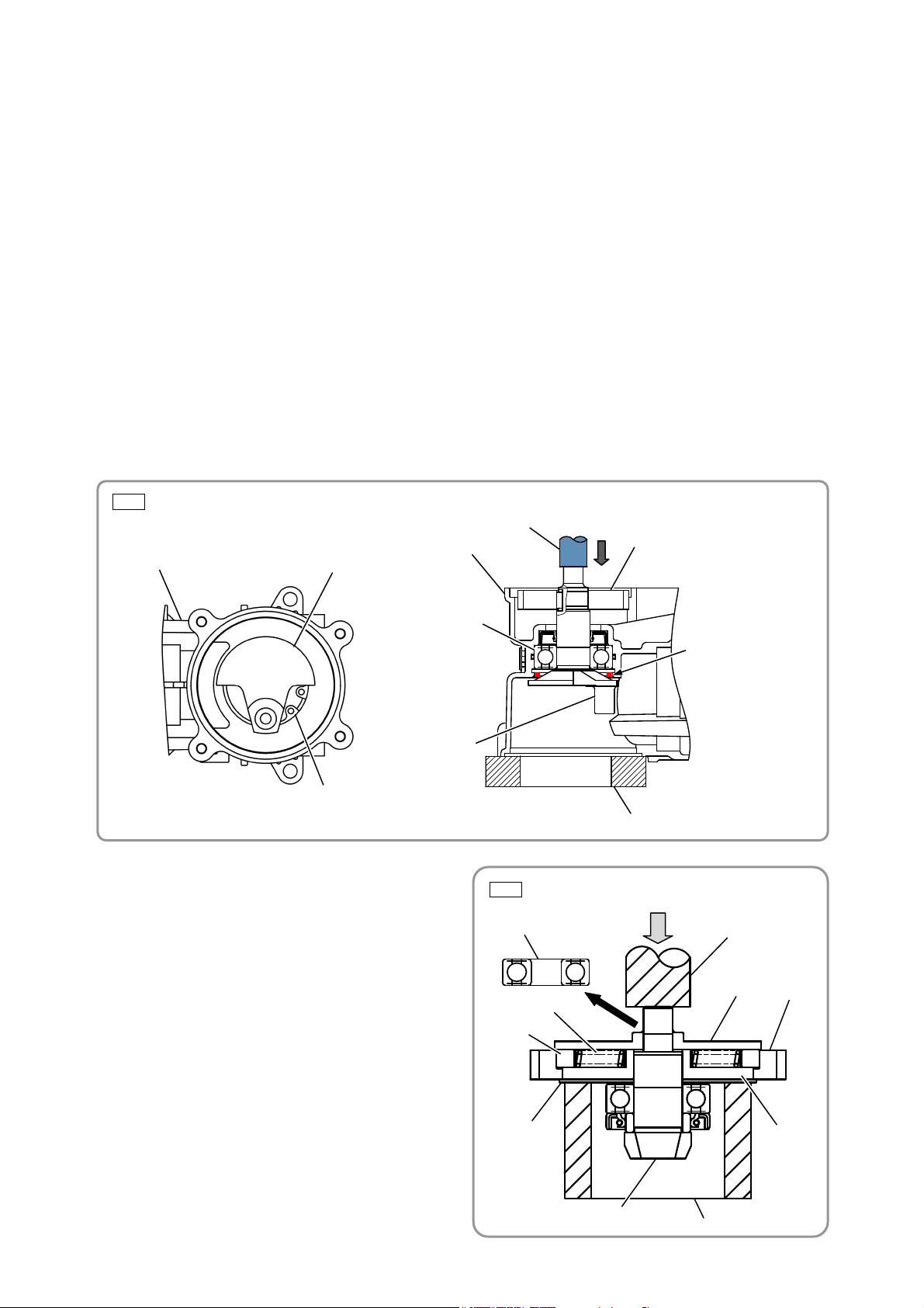
(4) Disassembly of the slip clutch ass’y
• Remove the Ball Bearing 629VV [106] by using
a bearing puller.
Fig. 6 • Disassembly of the slip clutch ass'y
[106]
Hand press
• Support Washer (A) [100] by an adequate
sleeve-like cradle as shown in Fig. 6.
• Use a hand press to press the Bevel Pinion [94]
on the Spacer [105] side.
[103]
[104]
[105]
[101]
• Detach the Gear Holder [102] and Spacer [105]
from the Bevel Pinion [94].
• When removing the Second Gear [101] from
the Gear Holder [102], put these parts in a
plastic bag and disassemble in the bag to avoid
[100]
[102]
losing Spring (C) [103] and Needle [104].
-3-
[94]
Cradle
Page 5
Reassembly
Reassembly can be accomplished by reversing the disassembly procedure. However, special attention
should be given to the following items.
1. Reassembly of the hammering mechanism
(1) Mounting the first gear and crank shaft
• Press-fit Oil Seal (B) [90] to the Crank Case Ass'y
[91].
• Mount the O-ring (S-40) [89].
• Press-fit the Ball Bearing 6203DD [88].
• Use a retaining ring puller to mount the Retaining
Ring for D40 Hole [87].
• Press-fit the Crank Shaft [85] to the Ball Bearing
6203DD [88].
• Insert the Feather Key 3 x 3 x 8 [86] into the
Crank Shaft [85] groove.
• Support the plane of the Crank Shaft [85] with an
adequate steel rod and use an adequate tool to
press-fit the First Gear [123].
NOTE: Prior to press-fitting, make sure the
Feather Key 3 x 3 x 8 [86] matches the
key groove of the First Gear [123].
(2) Mounting the piston
• Insert the Connecting Rod [48] into the Piston [47], and then press-fit the Piston Pin [46] from the D8
hole (marked side) of the Piston [47].
NOTE: Be careful not to let the Piston Pin [46] project from the outer diameter of the Piston [47].
• Mount the O-ring [45] on the Piston [47] to make the piston ass’y.
• Next, turn the Crank Shaft [85] to the position shown below, and then mount the piston ass’y to the
Crank Shaft [85] from the Cylinder Case [22] side of the Crank Case Ass'y [91].
NOTE: The piston ass’y can be assembled even when the Bevel Gear [43] and Slip Clutch
Ass’y [93] are mounted to the Crank Case Ass'y [91].
Fig. 8 • Mounting the piston
[47]
[46]
“Φ2” concavity mark
[48]
Fig. 7 • Mounting the first gear and crank shaft
Adequate tool
[86]
[123]
[90]
[89]
[88]
[85]
[91]
Adequate steel rod
[85]
[87]
[45]
-4-
Page 6
(3) Mounting the cylinder and retainer sleeve
• Mount the Retainer Damper Washer [26], Damper Sleeve [25], and Retainer Damper (B) [24] to the
Retainer Sleeve [28] in this order, while aligning the rounded surface of the Retainer Damper Washer
[26] with the rounded surface of the Retainer Sleeve [28].
• Insert the Second Hammer [30] (equipped with O-ring (C) [29]), Damper Washer [31], Damper [32],
and Damper Holder [33] into the Retainer Sleeve [28] in this order, while aligning the rounded surface
of the Damper Washer [31] with the rounded surface of the Second Hammer [30].
• Insert the assembly of the Retainer Sleeve [28] into the Cylinder Case [22].
NOTE: Be careful not to curl the lip of the oil seal.
• After inserting the Thrust Washer [44] and the Bevel Gear [43] into the Crank Case Ass'y [91], insert
the Slider [42] into the outer periphery of the Bevel Gear [43] along the Crank Case Ass'y [91] groove.
NOTE: The Bevel Gear [43] cannot be inserted if the Slip Clutch Ass'y [93] is mounted to the
Crank Case Ass'y [91] on ahead.
• Insert the Clutch [41] so that it engages with the internal claw of the Bevel Gear [43].
• Insert the Striker [34] equipped with the O-ring [35] into the Cylinder [36]. Fit the Clutch Spring [40] to
the Cylinder [36], and then insert the assembly of the Cylinder [36] into the Crank Case Ass'y [91].
• Insert the Lock Sleeve [39] into the Crank Case Ass'y [91], while aligning the inner spline groove of the
Crank Case Ass'y [91] with the Lock Sleeve [39] spline.
• Place the Lock Spring [38] and Spring Holder (B) [37] on the Lock Sleeve [39].
• Fit the protrusion of the Retainer Sleeve [28] in the Cylinder [36]
groove, and then mount the Cylinder
Case [22] equipped with the Retainer Sleeve [28] to the Crank Case Ass'y [91] equipped with the
Cylinder [36].
Fig. 9 • Mounting the cylinder and retainer sleeve
[28]
[22]
Be careful of the mounting direction.
[31]
[32]
[33]
[30]
[24]
[25] [26]
[37]
Be careful of the mounting direction.
[41]
[39]
[40]
[42]
[44]
[43]
[85]
[34]
[38]
[47]
[48]
-5-
Page 7

(4) Reassembly of the slip clutch ass’y
• Press-fit the Collar [96] and Ball Bearing 6002DD [98] in this order to the Bevel Pinion [94], and then
insert the Washer [99] and Washer (A) [100] in this order.
• Mount the Feather Key 3 x 3 x 8 [95] to the Bevel Pinion [94] and press-fit the Gear Holder [102].
• Insert the Second Gear [101] into the outer periphery of the Gear Holder [102]. Apply Hitachi Motor
Grease No. 29 to the inner periphery of the Second Gear [101] in advance.
• Insert the ten Needles [104] upright as shown below, and then push in ten Springs (C) [103].
• Fill up the slotted groove and through-hole portions of the Gear Holder [102] with Hitachi Motor Grease
No. 29, and then press-fit the Spacer [105] and Ball Bearing 629VV [106] to the Bevel Pinion [94] in
this order.
Fig. 10 • Reassembly of the slip clutch ass'y
[102]
[100]
[94]
[96]
[98]
[99]
[101]
[94]
[104]
A
[101]
[106]
[105]
A
Slotted groove in
the gear holder
[103]
[95]
Section A—A
(5) Mounting the lever shaft holder
• Apply Hitachi Motor Grease No. 29 to the O-ring (S-18) [115], and then attach the O-ring to the Change
Lever [112]. Insert the Lever Spring [113] into the change lever hole.
• Apply Hitachi Motor Grease No. 29 to the Steel Ball D4.76 [114] and place it into the concave portion of
the Lever Shaft Holder [116].
• Position the Lever Spring [113] and Steel Ball D4.76 [114] properly. Insert the Change Lever [112] into
the hole of the Lever Shaft Holder [116] and fix it with the Retaining Ring for D20 Shaft [118].
NOTE: Rotate the Change Lever [112] to check that the lever clicks at each mode position.
Insert the Change Lever [112] into the Lever Shaft Holder [116] straight to avoid
damaging the O-ring.
Fig. 11 • Mounting the lever shaft holder
[116]
[112]
[113]
[115]
[114]
[118]
-6-
Page 8

(6) Mounting the crank cover
• Insert the stepped portions of the Change Plate [119] into the notches of the Slider [42].
NOTE: Be careful of the inserting direction. See the figure below.
• Mount the Cylinder O-ring [117] to the outer diameter portion on the bottom of the Lever Shaft Holder
[116]. Set the Change Lever [112] to "Rotation + Hammering" mode position.
• Put the assembly of the Lever Shaft Holder [116] and Crank Cover [111] on the Crank Case Ass'y [91]
and fix them with the Hex. Socket Hd. Bolts M5 [110].
NOTE: After tightening the Hex. Socket Hd. Bolts M5 [110], check the following:
• The Change Lever [112] rotates smoothly.
• The Retainer Sleeve [28] is kept from rotating when the Change Lever [112] is set to
"Hammering" mode.
• The Retainer Sleeve [28] rotates smoothly when the Change Lever [112] is set to
"Neutral" mode.
Fig. 12 • Inserting the change plate
[119]
[42]
Notch of the Slider [42]
Stepped portion of the Change Plate [119]
-7-
Page 9

Lubrication points and types of lubricant
Specified grease (for hammer and hammer drill)
• Fill 20 g of specified grease in the Cylinder Case [22].
• Fill 69 g of specified grease in the Crank Case Ass'y [91] on the Connecting Rod [48] side.
• Apply specified grease to the inside and outside of the Cylinder [36].
• Apply specified grease to the inner diameter portion of the Connecting Rod [48].
• Apply specified grease to the sliding portion of the Second Hammer [30] and O-ring (C) [29] of the
Second Hammer [30].
• Apply specified grease to the sliding portion of the Striker [34] and O-ring [35] of the Striker [34].
• Apply specified grease to the outer diameter portion of the Piston [47] and O-ring [45] of the Piston
[47].
• Apply specified grease to the inner lips of Oil Seal (A) [97].
• Apply specified grease to the inner lips of Oil Seal (B) [90].
• Apply specified grease to the inner and outer diameter portions of the Bevel Gear [43].
• Apply specified grease to the Thrust Washer [44].
• Apply specified grease to the inner lip of the Oil Seal [20].
• Apply specified grease to the inside of the Clutch [41].
• Apply specified grease to the Damper [32].
• Apply specified grease to Retainer Damper (B) [24].
Hitachi Motor Grease No. 29
• Fill a total of 20 g of Hitachi Motor Grease No. 29 in the Crank Case Ass'y [91] on the First Gear [123]
side and the Gear Cover [108] side.
• Fill a total of 5 g of Hitachi Motor Grease No. 29 in the slotted groove and the 6 mm dia. holes of the
Gear Holder [102].
• Apply Hitachi Motor Grease No. 29 to the Needle Bearing [124].
• Apply Hitachi Motor Grease No. 29 to the pinion portion of the Armature [74].
• Apply Hitachi Motor Grease No. 29 to the Bit Lock [27].
Fig. 13 • Specified grease (for hammer and hammer drill)
500 g
Net weight Code No.
500 g 980927
70 g 308471
30 g 981840
70 g
30 g
CAUTION: Both viscosity and consistency of the specified grease are optimized for the
rotary hammer Model DH 40MC in order to prolong the service life. Therefore,
applying ordinary grease intended for other models to the Model DH 40MC may
dramatically shorten the product’s service life.
-8-
Page 10

Tightening torque
CAUTION: Be sure to apply TB1401 screw locking agent to the threads of the following screws and
bolts before tightening. Otherwise, the screw or bolt loosened by vibration may cause
damage to the tool body.
Item No. Part name
[21]
[50]
[65]
[75]
[80]
[84]
[92]
[109]
[110]
[121]
[127]
After completing disassembly and repair, measure the insulation resistance and dielectric strength.
Insulation resistance: 7 MΩ or higher (as measured with a 500 VDC megohm tester)
Dielectric strength:
(and 110 V for UK products)
(except UK products)
After no-load operation for 30 minutes, the no-load current values should be as follows:
Hex. Socket Hd. Bolt (W/Flange) M6 x 25 4 10 to 12 7.4 to 8.9
Hex. Hd. Tapping Screw D5 x 55 2 3.0 ± 0.5 2.2 ± 0.4
Tapping Screw (W/Flange) D5 x 20 (Black) 4 3.0 ± 0.5 2.2 ± 0.4
Hex. Socket Hd. Bolt (W/Flange) M5 x 16 2 6 to 8 4.4 to 5.9
Tapping Screw (W/Flange) D4 x 25 (Black) 2 2.0 ± 0.5 1.5 ± 0.4
Tapping Screw (W/Flange) D4 x 16 2 2.0 ± 0.5 1.5 ± 0.4
Seal Lock Hex. Socket Hd. Bolt M6 x 45 4 10 to 12 7.4 to 8.9
Seal Lock Hex. Socket Hd. Bolt M6 x 20 2 10 to 12 7.4 to 8.9
Hex. Socket Hd. Bolt (W/Flange) M5 x 18 4 8 to 10 5.9 to 7.4
Cap Screw 1 7 to 9 5.2 to 6.6
Hex. Socket Hd. Bolt (W/Flange) M5 x 12 1 4.0 ± 0.5 3.0 ± 0.4
Insulation test
4,000 VAC/1 minute, with no abnormalities ----- 220 V – 240 V
2,500 VAC/1 minute, with no abnormalities ----- 110 V – 127 V
No-load current value
No.
used
Tightening torque
N•m lbf-ft
Voltage
Current max.
110 V 120 V 127 V 220 V 230 V 240 V
6.5 A 5.9 A 4.6 A 3.4 A 3.3 A 3.2 A
-9-
Page 11

Connecting diagram
Fig. 14 • Connecting diagram
<For the USA, Canada, Mexico, and Panama (120 V)>
Stator Ass'y [
54]
Switch [78]
Connector [68]
Armature Ass'y
[74]
A
Stator Ass'y [
54]
Pillar Terminal [67]
<For Taiwan, Australia, New Zealand, Europe, South Africa, Turkey, Vietnam, Russia, China, and Korea>
(Inside the Stator Ass'y [
Armature Ass'y [74]
(Inside the Stator Ass'y [
Choke coil
54])
Choke coil
54])
A
Stator Ass'y [
54]
Noise Suppressor (V) [66]
Switch [78]
Connector [68]
Stator Ass'y [54]
Pillar Terminal [67]
<For the other countries>
Stator Ass'y [
54]
Switch [78]
Cord [70]
Cord
[70]
A
Stator Ass'y [54]
Connector [68]
Cord [70] Armature Ass'y [74]
Connector [68]
-10-
Page 12

STANDARD REPAIR TIME (UNIT) SCHEDULES
MODEL
DH 40MC
Variable
General assembly
10 min. 20 min. 30 min. 40 min. 50 min. 60 min.
Work Flow
Handle
Cover
Switch
Cord
Cord Armor
Tail Cover
Hood
Crank Cover
Change
Lever
Lever Shaft
Holder
Change
Plate
Front Cap
Grip
Retainer
Washer
Retainer
Damper (A)
Bit Lock
Holder
Bit Lock
Thrust Plate
Retainer
Spring
Spring
Holder (A)
Handle
Cylinder
Retainer
Retainer
Damper (B)
Damper
Sleeve
Retainer
Damper
Second
Damper
Damper
Damper
Case
Sleeve
Washer
Hammer
Washer
Holder
Cylinder
Striker
O-ring
Clutch
Lock Sleeve
Spring
Holder (B)
Lock Spring
Clutch
Spring
Slider
Piston
O-ring
Connecting
Rod
Gear Cover
Armature
Ball Bearing
6201DD
Ball Bearing
629VV
Crank Shaft
Ball Bearing
6203DD
First Gear
Slip Clutch
Ass’y
Bevel Gear
Housing
Stator Ass'y
Crank Case
Ass'y
-11-
Page 13

LIST NO. F440
ROTARY HAMMER
Model DH 40MC
9
8
1
2
3
4
5
11
12
13
24
56
14
25
37
49
50
51
52
53
54
55
57
15
26
27
38
39
40
58
59
60
61
62
63
64
67
16
28
29
41
72
73
74
66
68
69
70
7
6
17
18
19
30
31
32
42
43
75
65
71
10
503
20
33
21
34
44
45
76
77
81
83
22
35
46
78
79
82
84
501
502
85
86
87
88
89
90
92
23
36
47
93
48
80
108
109
2016 · 12· 7
91
94
95
96
97
98
99
100
101
102
103
104
105
106
107
(E1)
110
111
112
113
114
115
116
117
118
119
122
121
120
123
124
125
126
127
65
Page 14

PARTS DH 40MC
DESCRIPTION REMARKS
1 371151 FRONT CAP 1
2 331540 STOPPER RING 1
3 371138 RETAINER WASHER 1
4 371152 RETAINER DAMPER (A) 1
5 330209 SIDE HANDLE 1
6 337577 WING BOLT 1
7 949859 ROLL PIN D2 X 8 (10 PCS.) 1
8 371135 MOUNT 1
9 949556 NUT M6 (10 PCS.) 1
10 331247 HANDLE BOLT 1
11 371133 GRIP 1
12 371157 BIT LOCK HOLDER 1
13 371159 THRUST PLATE 1
14 371167 RETAINER SPRING 1
15 371145 SPRING HOLDER (A) 1
16 331246 BAND 1
17 371141 RETAINING RING D55 1
18 6907DD BALL BEARING 6907DDU 1
19 371142 BEARING WASHER 1
20 371148 OIL SEAL 1
21 991712
HEX. SOCKET HD. BOLT (W/FLANGE) M6 X 25 4
22 371125 CYLINDER CASE 1
23 956996 O-RING (1AS-60) 1
24 371153 RETAINER DAMPER (B) 1
25 371144 DAMPER SLEEVE 1
26 371161 RETAINER DAMPER WASHER 1
27 370654 BIT LOCK 2
28 371155 RETAINER SLEEVE 1
29 313396 O-RING (C) 1
30 371160 SECOND HAMMER 1
31 371163 DAMPER WASHER 1
32 371316 DAMPER 1
33 371164 DAMPER HOLDER 1
34 371165 STRIKER 1
35 986104 O-RING 1
36 371156 CYLINDER 1
37 331533 SPRING HOLDER (B) 1
38 331534 LOCK SPRING 1
39 331535 LOCK SLEEVE 1
40 371166 CLUTCH SPRING 1
41 371137 CLUTCH 1
42 371147 SLIDER 1
43 371158 BEVEL GEAR 1
44 331234 THRUST WASHER 1
45 986104 O-RING 1
46 331221 PISTON PIN 1
47 326369 PISTON 1
48 371175 CONNECTING ROD 1
49 371172 FAN GUIDE 1
50 953174 HEX. HD. TAPPING SCREW D5 X 55 2
- 2 - 12 - 16
*ALTERNATIVE PARTS
ITEM
NO.
NO.
USED
CODE NO.
Page 15

PARTS DH 40MC
DESCRIPTION REMARKS
51 371123 STATOR HOLDER 2
52 338755 RUBBER BUSH 2
53 930703 BRUSH TERMINAL 2
* 54 340963C STATOR ASS'Y 110V 1 INCLUD.53
* 54 340963D STATOR ASS'Y 120V 1 INCLUD.53
* 54 340963K STATOR ASS'Y 127V 1 INCLUD.53
* 54 340963M STATOR ASS'Y 220V 1 INCLUD.53
* 54 340963L STATOR ASS'Y 220V 1 INCLUD.53 FOR CHN
* 54 340963E STATOR ASS'Y 230V 1 INCLUD.53
* 54 340963H STATOR ASS'Y 230V 1 INCLUD.53 FOR SIN,IND
* 54 340963F STATOR ASS'Y 240V 1 INCLUD.53
* 54 340963J STATOR ASS'Y 240V 1 INCLUD.53 FOR MAL
55 371174 HOUSING ASS'Y 1 INCLUD.58,59
56 945161 BRUSH CAP 2
57 999043 CARBON BRUSH (1 PAIR) 1
57 999073
CARBON BRUSH (AUTO STOP TYPE) (1 PAIR) 1
58 958900 BRUSH HOLDER 2
59 938477 HEX. SOCKET SET SCREW M5 X 8 2
60 958915 WASHER (A) 1
61 629VVM BALL BEARING 629VV 1
62 371139 BEARING HOLDER 1
63 331547 DUST SEAL 1
64 371127 TAIL COVER 1
65 302089
TAPPING SCREW (W/FLANGE) D5 X 20 (BLACK) 4
* 66 371177 NOISE SUPPRESSOR (V) 1
FOR EUROPE,GBR,AUS,NZL,SAF,RUS,TUR,CHN
* 67 938307 PILLAR TERMINAL 1 EXCEPT FOR THA,INA,SIN,MAL,IND,PAN (220V)
* 68 959141 CONNECTOR 50092 (10 PCS.) 1
* 68 959141 CONNECTOR 50092 (10 PCS.) 2
FOR THA,INA,SIN,MAL,IND,PAN (220V)
69 NAME PLATE 1
* 70 500390Z CORD 1 (CORD ARMOR D8.2)
* 70 500434Z CORD 1 (CORD ARMOR D8.2) FOR USA,CAN,
MEX,PAN (120V)
* 70 500235Z CORD 1
(CORD ARMOR D8.2) FOR INA,IND,PAN (220V)
* 70 500439Z CORD 1 (CORD ARMOR D8.2) FOR AUS,NZL
* 70 500440Z CORD 1 (CORD ARMOR D8.2) FOR SIN,MAL
* 70 500446Z CORD 1
(CORD ARMOR D8.2) FOR GBR (230V)
* 70 500467Z CORD 1 (CORD ARMOR D10.7) FOR GBR (110V)
* 70 500457Z CORD 1 (CORD ARMOR D10.7) FOR CHN
* 70 500239Z CORD 1 (CORD ARMOR D10.7) FOR THA
* 71 940778 CORD ARMOR D10.7 1
* 71 958049 CORD ARMOR D8.2 1
72 6201DD BALL BEARING 6201DDCMPS2L 1
73 325003 DUST WASHER (B) 1
* 74 361058C ARMATURE 110V 1
* 74 361058U ARMATURE ASS'Y 120V 1 INCLUD.60,61,72,73
* 74 361058G ARMATURE 127V 1
* 74 361058H ARMATURE 220V 1
* 74 361058E ARMATURE 230V 1
* 74 361058F ARMATURE 240V 1
75 994192
HEX. SOCKET HD. BOLT (W/FLANGE) M5 X 16 2
12 - 16 - 3 -
*ALTERNATIVE PARTS
NO.
USED
CODE NO.
ITEM
NO.
Page 16

PARTS DH 40MC
DESCRIPTION REMARKS
76 371129 HANDLE 1
77 371128 TRIGGER 1
78 371171 SWITCH 1
79 371130 HANDLE COVER 1
80 307028
TAPPING SCREW (W/FLANGE) D4 X 25 (BLACK) 2
* 81 980063 TERMINAL 1
* 81 930804 TERMINAL M4.0 (10 PCS.) 1
FOR USA,CAN,MEX,PAN (120V),GBR (110V)
82 371149 INTERNAL WIRE 1
83 960266 CORD CLIP 1
84 984750 TAPPING SCREW (W/FLANGE) D4 X 16 2
85 371136 CRANK SHAFT 1
86 944109 FEATHER KEY 3 X 3 X 8 1
87 948391 RETAINING RING FOR D40 HOLE 1
88 6203DD BALL BEARING 6203DDCMPS2L 1
89 996363 O-RING (S-40) 1
90 321274 OIL SEAL (B) 1
91 371173 CRANK CASE ASS'Y 1 INCLUD.121,122
92 986940
SEAL LOCK HEX. SOCKET HD. BOLT M6 X 45 4
93 371176 SLIP CLUTCH ASS'Y 1 INCLUD.94-96,98-106
94 331211 BEVEL PINION 1
95 944109 FEATHER KEY 3 X 3 X 8 1
96 321279 COLLAR 1
97 313050 OIL SEAL (A) 1
98 6002DD BALL BEARING 6002DDCMPS2L 1
99 331213 WASHER 1
100 331214 WASHER (A) 1
101 331215 SECOND GEAR 1
102 321281 GEAR HOLDER 1
103 321282 SPRING (C) 10
104 331217 NEEDLE 10
105 331219 SPACER 1
106 629VVM BALL BEARING 629VV 1
107 331220 BEARING WASHER (C) 1
108 371124 GEAR COVER 1
109 992803
SEAL LOCK HEX. SOCKET HD. BOLT M6 X 20 2
110 371170 HEX. SOCKET HD. BOLT (W/FLANGE) M5 4
111 371131 CRANK COVER 1
112 371134 CHANGE LEVER 1
113 371168 LEVER SPRING 1
114 959149 STEEL BALL D4.76 (10 PCS.) 1
115 878885 O-RING (S-18) 1
116 371126 LEVER SHAFT HOLDER 1
117 877315 CYLINDER O-RING (I.D 63.9) 1
118 939547 RETAINING RING FOR D20 SHAFT (10 PCS.) 1
119 371146 CHANGE PLATE 1
120 371178 FELT PACKING (A) 1
121 371179 CAP SCREW 1
122 995396 VALVE 1
123 371162 FIRST GEAR 1
124 371169 NEEDLE BEARING 1
- 4 - 12 - 16
*ALTERNATIVE PARTS
NO.
USED
CODE NO.
ITEM
NO.
Page 17

DH 40MC
DESCRIPTION REMARKS
125 371143 SEAL PACKING 1
126 371132 HOOD 1
127 998471
HEX. SOCKET HD. BOLT (W/FLANGE) M5 X 12 1
DESCRIPTION REMARKS
501 371122 CASE 1
502 981840
GREASE (A) FOR HAMMER.HAMMER DRILL (30G) 1
503 971786 STOPPER ROD 1
12 - 16 Printed in Japan - 5 -
(161207N)
*ALTERNATIVE PARTS
PARTS
STANDARD ACCESSORIES
NO.
USED
CODE NO.
ITEM
NO.
CODE NO.
NO.
USED
CODE NO.
ITEM
NO.
 Loading...