

Page 1

MODEL ROTARY HAMMER
MODÈLE MARTEAU ROTATIF
MODELO MARTILLO GIRATORIO
DH 40FB
INSTRUCTION MANUAL AND SAFETY INSTRUCTIONS
WARNING
Improper and unsafe use of this power tool can result in death or serious bodily
injury!
This manual contains important information about product safety. Please read
and understand this manual before operating the power tool. Please keep this
manual available for others before they use the power tool.
MODE D’EMPLOI ET INSTRUCTIONS DE SECURITE
AVERTISSEMENT
Une utilisation incorrecte et dangereuse de cet outil motorisé peut entraîner la
mort ou de sérieuses blessures corporelles!
Ce mode d’emploi contient d’importantes informations à propos de la sécurité de
ce produit. Prière de lire et de comprendre ce mode d’emploi avant d’utiliser l’outil
motorisé. Garder ce mode d’emploi à la disponibilité des autres utilisateurs avant
qu’ils utilisent l’outil motorisé.
MANUAL DE INSTRUCCIONES E INSTRUCCIONES DE SEGURIDAD
ADVERTENCIA
¡La utilización inapropiada e insegura de esta herramienta eléctrica puede resultar
en lesiones serias o en la muerte!
Este manual contiene información importante sobre la seguridad del producto.
Lea y comprenda este manual antes de utilizar la herramienta eléctrica. Guarde
este manual para que puedan leerlo otras personas antes de que utilicen la
herramienta eléctrica.
DOUBLE INSULATION
DOUBLE ISOLATION
AISLAMIENTO DOBLE
Page 2

English
IMPORTANT INFORMATION ............ 3
MEANINGS OF SIGNAL WORDS ..... 3
SAFETY ...................................................... 4
GENERAL SAFETY RULES.................... 4
SPECIFIC SAFETY RULES AND
SYMBOLS........................................... 7
DOUBLE INSULATION FOR SAFER
OPERATION ....................................... 8
FUNCTIONAL DESCRIPTION.................... 9
MANE OF PARTS................................... 9
SPECIFICATIONS ................................... 9
CONTENTS
Page
ASSEMBLY AND OPERATION ............... 10
Page
APPLICATIONS .................................... 10
PRIOR TO OPERATION ....................... 10
HOW TO USE ....................................... 11
HOW TO USE THE CORE BIT ............. 14
MAINTENANCE AND INSPECTION ....... 16
ACCESSORIES ......................................... 18
STANDARD ACCESSORIES ................ 18
OPTIONAL ACCESSORIES.................. 18
PARTS LIST.............................................. 54
Français
INFORMATIONS IMPORTANTES ....... 20
SIGNIFICATION DES MOTS
D’AVERTISSEMENT ........................ 20
SECURITE ................................................ 21
REGLES GENERALES DE SECURITE . 21
REGLES DE SECURITE SPECIFIQUES ET
SYMBOLES ...................................... 24
DOUBLE ISOLATION POUR UN
FONCTIONNEMENT PLUS SUR ..... 25
DESCRIPTION FONCTIONNELLE ........... 26
NOM DES PARTIES ............................. 26
SPECIFICATIONS ................................. 26
TABLE DES MATIERES
Page
Español
INFORMACIÓN IMPORTANTE ........... 37
SIGNIFICADO DE LAS PALABRAS DE
SEÑALIZACIÓN................................ 37
SEGURIDAD............................................. 38
NORMAS GENERALES DE SEGURIDAD
NORMAS Y SÍMBOLOS ESPECÍFICOS
DE SEGURIDAD ............................... 41
AISLAMIENTO DOBLE PARA OFRECER
UNA OPERACIÓN MÁS SEGURA .. 42
DESCRIPCIÓN FUNCIONAL.................... 43
NOMENCLATURA ............................... 43
ESPECIFICACIONES ............................ 43
Página
.. 38
ASSEMBLAGE ET FONCTIONNEMENT ....
APPLICATIONS .................................... 27
AVANT L’UTILISATION ....................... 27
UTILISATION ....................................... 28
COMMENT UTILISER LA
COURONNE ..................................... 31
ENTRETIEN ET INSPECTION .................. 33
ACCESOIRES ........................................... 35
ACCESSOIRES STANDARD ................ 35
ACCESSOIRES SUR OPTION.............. 35
LISTA DES PIÈCES .................................. 54
ÍNDICE
MONTAJE Y OPERACIÓN ...................... 44
APLICACIONES .................................... 44
ANTES DE LA OPERACIÓN ................ 44
MODE DE UTILIZACIÓN...................... 46
MODO DE USAR LA BARRENA
TUBULAR ......................................... 48
MANTENIMIENTO E INSPECCIÓN ........ 50
ACCESORIOS........................................... 52
ACCESORIOS ESTÁNDAR .................. 52
ACCESORIOS OPCIONALES............... 52
LISTA DE PIEZAS .................................... 54
Page
27
Página
Page 3

English
IMPORTANT INFORMATION
Read and understand all of the operating instructions, safety precautions and
warnings in the Instruction Manual before operating or maintaining this power tool.
Most accidents that result from power tool operation and maintenance are caused
by the failure to observe basic safety rules or precautions. An accident can often be
avoided by recognizing a potentially hazardous situation before it occurs, and by
observing appropriate safety procedures.
Basic safety precautions are outlined in the “SAFETY” section of this Instruction
Manual and in the sections which contain the operation and maintenance
instructions.
Hazards that must be avoided to prevent bodily injury or machine damage are
identified by WARNINGS on the power tool and in this Instruction Manual.
Never use this power tool in a manner that has not been specifically recommended
by HITACHI, unless you first confirm that the planned use will be safe for you and
others.
MEANINGS OF SIGNAL WORDS
W ARNING indicates a potentially hazardous situations whic h, if ignored, could result
in serious personal injury.
CAUTION indicates a hazardous situations which, if ignored, could result in moderate
personal injury, or could cause machine damage.
NOTE emphasizes essential information.
3
Page 4
English
SAFETY
GENERAL SAFETY RULES
WARNING: Read and understand all instructions.
Failure to follow all instructions listed below, may result in electric
shock, fire and/or serious personal injury.
SA VE THESE INSTRUCTIONS
1. Work Area
(1) Keep your work area clean and well lit. Cluttered benches and dark areas
invite accidents.
(2) Do not operate power tools in explosive atmospheres, such as in the presence
of flammable liquids, gases, or dust. Power tools create sparks which may
ignite the dust or fumes.
(3) Keep bystanders, children, and visitors away while operating a power tool.
Distractions can cause you to lose control.
2. Electrical Safety
(1) Double Insulated tools are equipped with a polarized plug (one blade is wider
than the other.) This plug will fit in a polarized outlet only one way. If the
plug does not fit fully in the outlet, reverse the plug. If it still does not fit,
contact a qualified electrician to install a polarized outlet. Do not change the
plug in any way. Double Insulation eliminates the need for the three wire
grounded power cord and grounded power supply system.
(2) Av oid body contact with grounded surfaces such as pipes, radiators, ranges
and refrigerators. There is an increased risk of electric shock if your body is
grounded.
(3) Don’t expose power tools to rain or wet conditions. Water entering a power
tool will increase the risk of electric shock.
(4) Do not abuse the cord. Never use the cord to carry the tools or pull the plug
from a receptacle. Keep cord away from heat, oil, sharp edges or moving
parts. Replace damaged cords immediately. Damaged cords increase the
risk of electric shock.
(5) When operating a power tool outside, use an outdoor extension cord marked
“W-A” or “W”. These cords are rated for outdoor use and reduce the risk of
electric shock.
3. Personal Safety
(1) Stay alert, w atch what you are doing and use common sense when oper ating
a power tool. Do not use tool while tired or under the influence of drugs,
alcohol, or medication. A moment of inattention while operating power tools
may result in serious personal injury.
(2) Dress properly. Do not wear loose clothing or jewelry. Contain long hair.
Keep your hair, clothing, and gloves awa y fr om moving par ts. Loose clothes,
jewelry, or long hair can be caught in moving parts.
4
Page 5

(3) Avoid accidental starting. Be sure switch is off before plugging in. Carrying
tools with your finger on the switch or plugging in tools that have the switch
on invites accidents.
(4) Remove adjusting keys or wrenches before turning the tool on. A wrench or
a key that is left attached to a rotating part of the tool may result in personal
injury.
(5) Do not overreach. Keep proper footing and balance at all times. Proper footing
and balance enables better control of the tool in unexpected situations.
(6) Use safety equipment. Always wear protective glasses. Dust mask, non-skid
safety shoes, hard hat, or ear plugs must be used for appropriate conditions.
4. Tool Use and Care
(1) Use clamps or other practical way to secure and support the workpiece to a
stable platform. Holding the work by hand or against your body is unstable
and may lead to loss of control.
(2) Do not force tool. Use the correct tool for your application. The correct tool
will do the job better and safer at the rate for which it is designed.
(3) Do not use tool if switch does not turn it on or off. Any tool that cannot be
controlled with the switch is dangerous and must be repaired.
(4) Disconnect the plug form the power source before making any adjustments,
changing accessories, or storing the tool. Such preventive safety measures
reduce the risk of starting the tool accidentally.
(5) Store idle tools out of reach of children and other untrained persons. T ools
are dangerous in the hands of untrained users.
(6) Maintain tools with care. Keep cutting tools sharp and clean. Properly
maintained tools, with sharp cutting edges are less likely to bind and are
easier to control.
(7) Check for misalignment or binding of moving parts, breakage of parts, and
any other condition that may affect the tools operation. If damaged, have
the tool serviced before using. Many accidents are caused by poorly
maintained tools.
(8) Use only accessories that are recommended by the manufacturer for your
model. Accessories that may be suitable for one tool, may become hazardous
when used on another tool.
5. Service
(1) Tool service must be performed only by qualified repair personnel. Service
or maintenance performed by unqualified personnel could result in a risk of
injury.
(2) When servicing a tool, use only identical replacement parts. Follow
instructions in the Maintenance section of this manual. Use of unauthorized
parts or failure to follow Maintenance Instruction may create a risk of electric
shock or injury.
6. Never touch moving parts.
Never place your hands, fingers or other body parts near the tool’ s moving par ts.
7. Never operate without all guards in place.
Never operate this tool without all guards or safety features in place and in proper
working order. If maintenance or servicing requires the removal of a guard or
safety feature, be sure to replace the guard or safety feature before resuming
operation of the tool.
English
5
Page 6

English
8. Use right tool.
Don’t force small tool or attachment to do the job of a heavy-duty tool.
Don’t use tool for purpose not intended — for example — don’t use circular saw
for cutting tree limbs or logs.
9. Never use a power tool for applications other than those specified.
Never use a power tool for applications other than those specified in the
Instruction Manual.
10.Handle tool correctly.
Operate the tool according to the instructions provided herein. Do not drop or
throw the tool. Never allow the tool to be operated by children, individuals
unfamiliar with its operation or unauthorized personnel.
11.Keep all screws, bolts and covers tightly in place.
Keep all screws, bolts, and plates tightly mounted. Check their condition
periodically.
12.Do not use power tools if the plastic housing or handle is cracked.
Cracks in the tool’s housing or handle can lead to electric shock. Such tools
should not be used until repaired.
13.Blades and accessories must be securely mounted to the tool.
Prevent potential injuries to yourself or others. Blades, cutting implements and
accessories which have been mounted to the tool should be secure and tight.
14.Keep motor air vent clean.
The tool’s motor air vent must be kept clean so that air can freely flow at all
times. Check for dust build-up frequently.
15.Operate power tools at the rated voltage.
Operate the power tool at voltages specified on its nameplate.
If using the power tool at a higher voltage than the rated voltage, it will result in
abnormally fast motor revolution and may damage the unit and the motor may
burn out.
16.Never use a tool which is defective or operating abnormally.
If the tool appears to be operating unusually, making strange noises, or otherwise
appears defective, stop using it immediately and arrange for repairs by a Hitachi
authorized service center.
17.Never leave tool running unattended. Turn power off.
Don’t leave tool until it comes to a complete stop.
18.Carefully handle power tools.
Should a power tool be dropped or struck against hard materials inadvertently,
it may be deformed, cracked, or damaged.
19.Do not wipe plastic parts with solvent.
Solvents such as g asolie, thinner, benzine, carbon tetrac hloride, and alcohol may
damage and crack plastic parts. Do not wipe them with such solvents.
Wipe plastic parts with a soft cloth lightly dampened with soapy water and dry
thoroughly.
6
Page 7

English
SPECIFIC SAFETY RULES AND SYMBOLS
1. Hold tools by insulated gr ipping surfaces when performing an operation where
the cutting tool may contact hidden wiring or its own cord. Contact with a “live”
wire will make exposed metal parts of the tool “live” and shock the operator.
2. Wear ear plugs when using the tool for extended periods. Prolonged exposure
to high intensity noise can cause hearing loss.
3. NEVER touch the tool bit with bare hands after operation.
4. NEVER wear gloves made of stuff liable to roll up such as cotton, wool, cloth or
string, etc.
5. ALWAYS attach the side handle and securely grip the Rotary Hammer.
6. ALWAYS be careful with buried object such as an underground wiring.
Touching these active wiring or electric cable with this tool, you may receive an
electric shock.
Comfirm if there are any buried object such as electric cable within the wall,
floor or ceiling where you are going to operate here after.
7. Definitions for symbols used on this tool
V .............volts
Hz ........... hertz
A ............. amperes
no ..........no load speed
W ............ watt
............Class II Construction
---/min ....revolutions per minute
7
Page 8

English
DOUBLE INSULATION FOR SAFER OPERATION
T o ensure safer operation of this power tool, HIT ACHI has adopted a double insulation
design. “Double insulation” means that two physically separated insulation systems
have been used to insulate the electrically conductive materials connected to the
power supply from the outer frame handled by the operator. Therefore, either the
symbol “ ” or the words and “Double insulation” appear on the power tool or on
the nameplate.
Although this system has no external grounding, you must still follow the normal
electrical safety precautions given in this Instruction Manual, including not using
the power tool in wet environments.
To keep the double insulation system effective, follow these precautions:
䡬 Only HITACHI AUTHORIZED SERVICE CEN TER should disassemble or assemble
this power tool, and only genuine HIT ACHI replacement parts should be installed.
䡬 Clean the exterior of the power tool only with a soft cloth moistened with soapy
water, and dry thoroughly.
Never use solvents, gasoline or thinners on plastic components; otherwise the
plastic may dissolve.
SAVE THESE INSTRUCTIONS
AND
MAKE THEM AVAILABLE TO
OTHER USERS OF THIS TOOL!
8
Page 9
FUNCTIONAL DESCRIPTION
NOTE:
The information contained in this Instruction Manual is designed to assist you in
the safe operation and maintenance of the power tool.
Some illustrations in this Instruction Manual may show details or attachments
that differ from those on your own power tool.
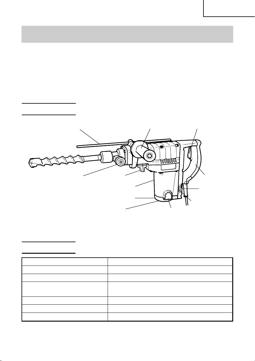
NAME OF PARTS
English
Stopper
Tool Holder
Side Handle
Selector Lever
Housing
Tail Cover
Set Screw
(Under the Tail Cover)
Fig. 1
Switch Trigger
Nameplate
Dial
Brush Cap
(Inside the Tail Cover)
SPECIFICATIONS
Motor Single-Phase, Series Commutator Motor.
Power Source Single-Phase, 115 V 60 Hz
Current 8.7 A
Capacity Drill Bit: 1-9/16" (40 mm)
Core Bit: 4-1/8" (105 mm)
No-Load Speed 180 – 360/min
Full-load Blow 1400 – 2800 bpm
Weight 15 lbs (6.8 kg)
Handle
9
Page 10
English
ASSEMBLY AND OPERATION
APPLICATIONS
Rotation and hammering function
䡬 Drilling anchor holes
䡬 Drilling holes in concrete
Hammering function only
䡬 Crushing concrete, chipping, digging, and squaring
(by applying optional accessories)
PRIOR TO OPERA TION
1. Power source
Ensure that the power source to be utilized conforms to the power source
requirements specified on the product nameplate.
2. Power switch
Ensure that the switch is in the OFF position. If the plug is connected to a
receptacle while the switch is in the ON position, the power tool will start operating
immediately and can cause serious injury.
3. Extension cord
When the work area is far away from the power source, use an extension cord of
sufficient thickness and rated capacity (refer to page 9). The extension cord should
be kept as short as practicable.
WARNING: Damaged cord must be replaced or repaired.
4. Check the receptacle
If the receptacle only loosely accepts the plug, the receptacle must be repaired.
Contact a licensed electrician to make appropriate repairs.
If such a fautly receptacle is used, it may cause overheating, resulting in a serious
hazard.
5. Confirming condition of the environment:
Confirm that the work site is placed under appropriate conditions conforming to
prescribed precautions.
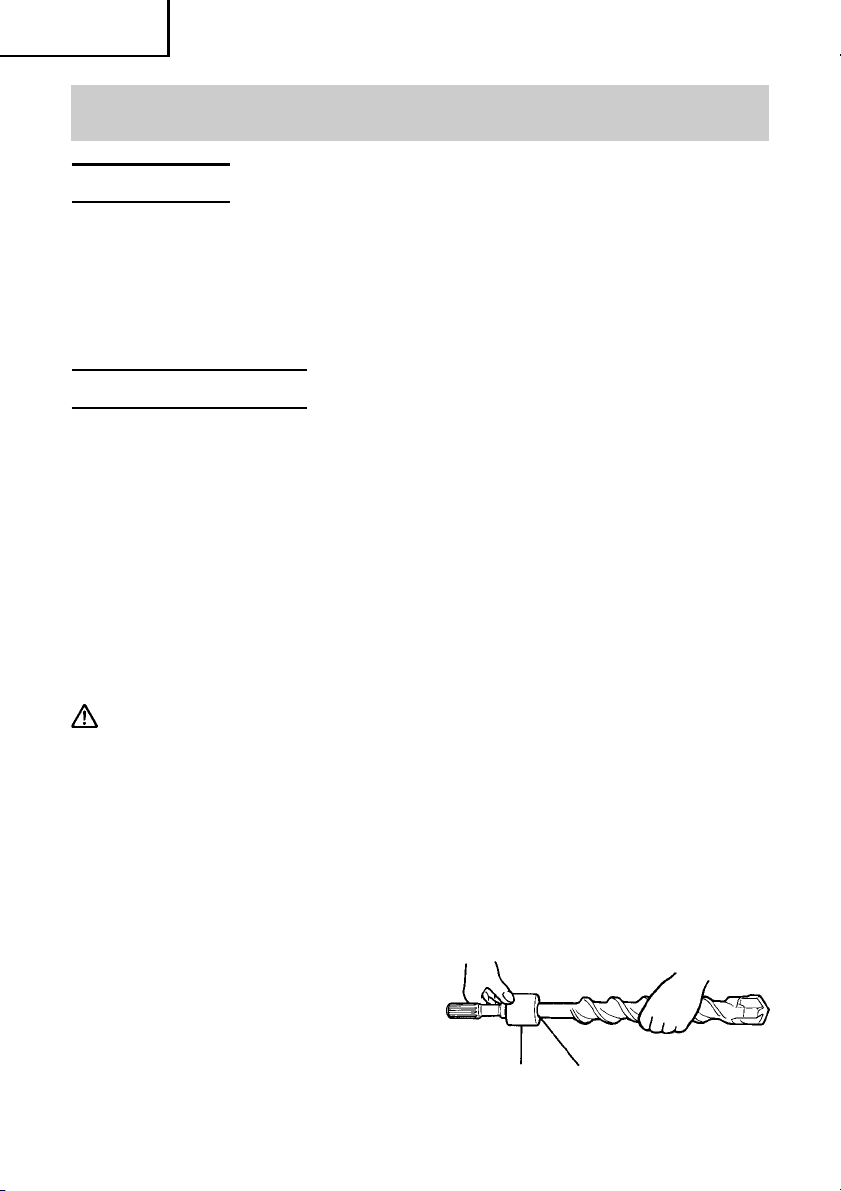
6. How to install dust cover (Fig. 2)
Always install the dust cover on the drill
bit or the taper shank adaptor. Insert the
dust cover until it lies flush in the
groove.
NOTE: For a thick drill bit, insert the
dust cover from drill rear.
10
Dust cover
Insert up to the groove
Fig. 2
Page 11
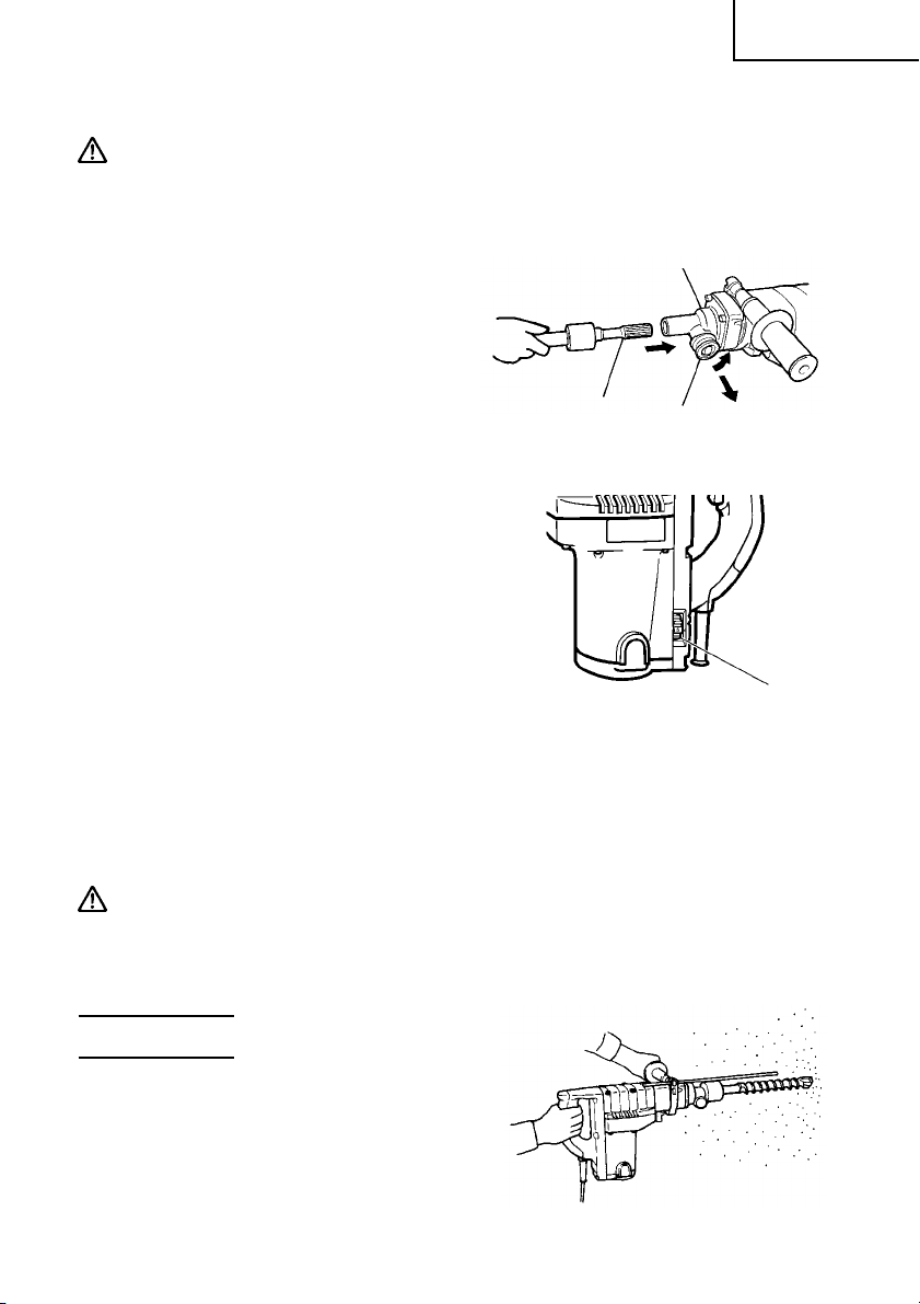
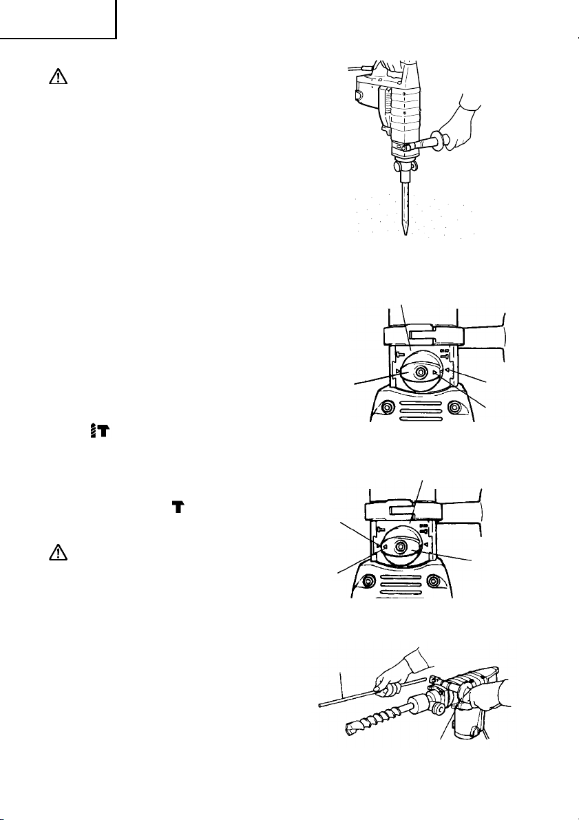
7. How to install tool
CAUTION: For tools such as a drill bit and a bull point, use only Hitachi genuine
parts.
(1) Clean, then smear the tool shank with
the grease provided in the green tube.
(2) Pull the tool holder in the direction of
arrow 1 and rotate it in the direction of
arrow 2 (counterclockwise). Fully inser t
the tool shank into the hexagonal hole
of the front cover. (Fig. 3)
(3) Return the tool holder to fix the tool.
NOTE: Remove in the reverse order to
installation.
Tool Shank
Front Cover
2
1
Tool Holder
Fig. 3
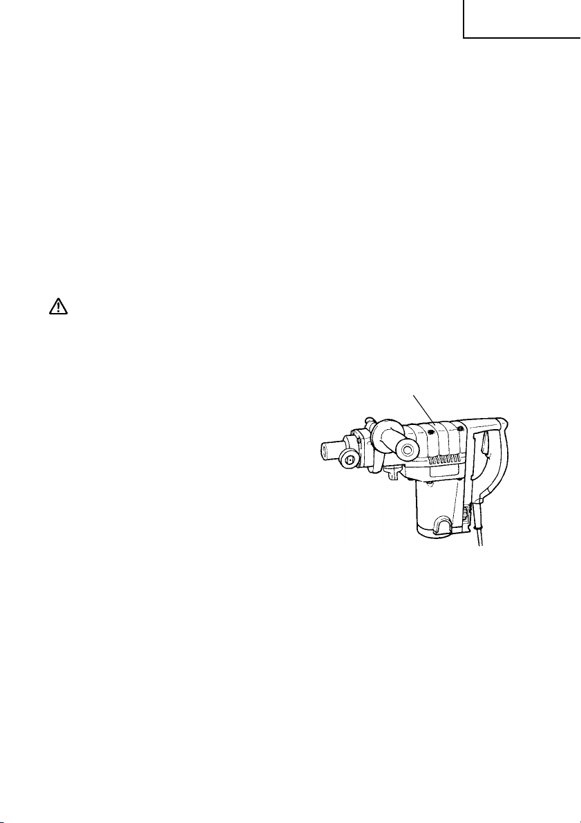
8. Regulating the number of rotations
and hammering (Fig. 4)
This rotary hammer is equipped with a
built-in electronic control circuit that can
adjust and regulate the number of
rotations and times of hammering. This
hammer drill can be used by adjusting
the dial, depending upon the contents
of operation, such as boring holes into
fragile materials, chipping, centering,
etc.
The scale ‘1’ of the dial is designed for a minimum speed with the number of 180
rotations per minute and 1,400 times of blow per minute. The scale ‘5’ is designed
for a maximum speed with the number of 360 rotations per minute and 2,800
times of blow per minute.
Fig. 4
English
Dial
CAUTION:
Do not adjust the dial during operation. Doing so can result in injury because
the rotary hammer must be held by only one hand, disabling the steady control
of the rotary hammer.
HOW TO USE
1. How to drill holes (Fig. 5)
(1) Pull the switch trigger after applying the
drill bit tip to the drilling position.
(2) It is unnecessary to forcibly press the
rotary hammer main body. It is suf ficient
to slightly press the rotary hammer to
an extent that clips are freely
discharged.
Fig. 5
11
Page 12
English
CAUTION:
Although this machine is equipped with
a safety clutch, if the drill bit becomes
bound in concrete or other material, the
resultant stoppage of the drill bit could
cause the machine body to turn in
reaction. Ensure that the main handle
and side handle are gripped firmly
during operation.
2. How to chisel or crush (Fig. 6)
By applying the tool tip to the chiseling
or crushing position, operate the rotary
hammer by utilizing its empty weight.
Forcible pressing or thrusting is
unnecessary.
3. How to select rotation-hammering
and hammering.
(1) Rotation-hammering (Fig. 7)
Rotate the selector lever clockwise so
that the ▲ mark on the selector lever is
aligned with the ▲ mark on the side of
the mark on the under cover.
(2) Hammering (Fig. 8)
Rotate the selector lever counterclockwise so that the ▲ mark on the
selector lever is aligned with the ▲ mark
on the side of the mark on the under
cover.
Selector
Lever
▲
Fig. 6
Under Cover
▲
▲
Fig. 7
Under Cover
CAUTION:
䡬 Turning the selector lever during motor
rotation will rotat e the tool accidentally .
The selector lever should only be turned
when the motor is stopped.
4. Install the stopper (Fig. 9)
(1) Loosen the side handle and insert the
straight portion of the stopper into the
handle bolt hole from the front cover.
(2) Loosen the side handle, move the
stopper to the specified position and
rotate the grip of the side handle
clockwise to fix the stopper.
12
▲
Stopper
Selector
Lever
Fig. 8
Side Handle
Fig. 9
Page 13
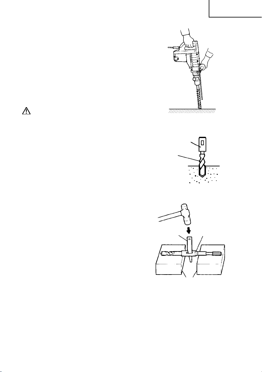
5. Warming up (Fig. 10)
The grease lubrication system in this
unit may require warming up in cold
regions.
Position the end of the bit so makes
contact with the concrete, turn on the
switch and perform the warming up
operation. Make sure that a hitting
sound is produced and then use the
unit.
CAUTION:
When the warming up operation is
performed, hold the side handle and the
main body securely with both hands to
maintain a secure grip and be careful
not to twist your body by the jammed
drill bit.
6. How to use the drill bit (taper shank)
and the taper shank adaptor.
(1) Install drill bit with taper shank in the
taper shank adaptor.
(2) T urn the power on and drill a base hole.
(3) After cleaning out dust with a syringe,
attach the plug to the anchor tip and
drive in the anchor with a manual
hammer.
(4) T o remo ve the drill bit with taper shank,
insert a cotter into the slot of the taper
shank adaptor, place supports under the
rotary hammer and tap the cotter with
a manual hammer. (Fig. 12)
Fig. 10
Taper Shank Adaptor
Drill Bit
(Taper shank)
Fig. 11
Cotter
English
Taper Shank
Adaptor
Support
Fig. 12
13
Page 14
English
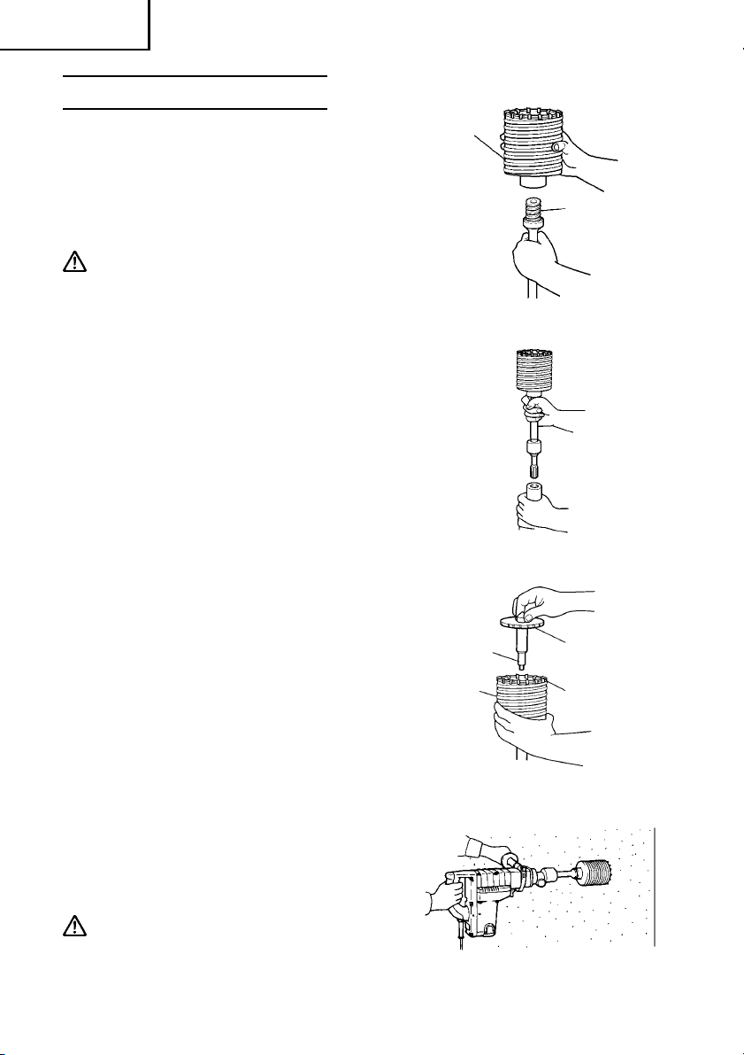
HOW TO USE THE CORE BIT
When boring penetrating large hole use the
core bit. At that time use with the center
pin and the core bit shank provided as
optional accessories.
1. Mounting
CAUTION:
Be sure to turn power OFF and disconnect
the plug from the receptacle.
(1) Mount the core bit to the core bit shank.
(Fig. 13)
Lubricate the thread of the core bit
shank to facilitate disassembly.
(2) Mount the core bit shank to the rotary
hammer. (Fig. 14)
(3) Insert the center pin into the guide plate
until it stops.
(4) Engage the guide plate with the core bit,
and turn the guide plate to left or right
so that it does not fall even if it faces
downward. (Fig. 15)
Core Bit
Core Bit
Shank
Fig. 13
Fig. 14
2. How to bore (Fig. 16)
(1) Connect the plug to the receptacle.
(2) A spring is installed in the center pin.
Push it lightly to the wall or the floor
straight. Connect all over the surface of
the core bit tip and start operating.
(3) When boring about 3/16" (5 mm) in
depth the position of the hole will
establish. Bore after that removing the
center pin and the guide plate from core
bit.
(4) Application of excessive force will not
only expedite the work, but will
deteriorate the tip edge of the drill bit,
resulting in reduced service life of the
rotary hammer.
CAUTION:
When removing the center pin and the
guide plate, turn OFF the switch and
disconnect the plug from the
receptacle.
14
Center Pin
Core Bit
Guide Plate
Core Bit Tip
Fig. 15
Fig. 16
Page 15
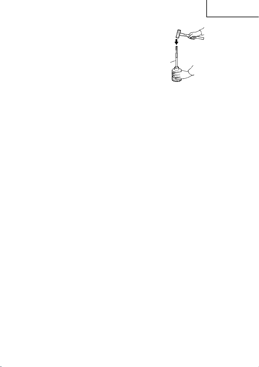
3. Dismounting (Fig. 17)
Remove the core bit shank from the
rotary hammer and strike the head of
the core bit shank strongly two or three
times with a manual hammer holding
the core bit, then the thread becomes
loose and the core bit can be removed.
English
Core Bit
Shank
Fig. 17
15
Page 16
English
MAINTENANCE AND INSPECTION
WARNING: Be sure to switch power OFF and disconnect the plug from the
receptacle during maintenance and inspection.
1. Inspecting the drill bits
Since use of a dull tool will cause motor malfunctioning and degraded efficiency ,
replace the drill bit with a new one or resharpening without delay when abrasion
is noted.
2. Inspecting the mounting screws
Regularly inspect all mounting screws and ensure that they are properly
tightened. Should any of the screws be loose, retighten them immediately.
WARNING: Using this rotary hammer with loosen screws is extremely
dangerous.
3. Maintenance of the motor
The motor unit winding is the very “heart” of the power tool. Exercise due care
to ensure the winding does not become damaged and/or wet with oil or water.
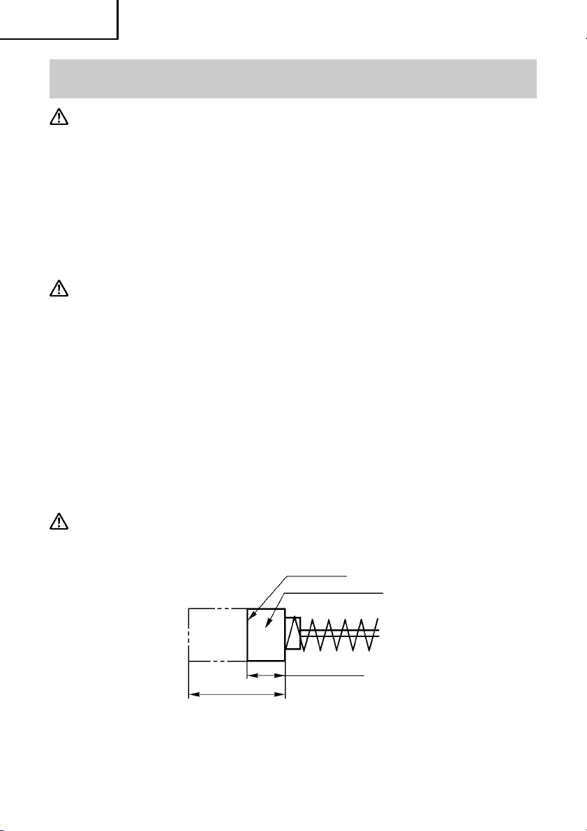
4. Inspecting the carbon brushes: (Fig. 18)
The motor employs carbon brushes which are consumable parts. When they
become worn to or near “wear limit”, it could result in motor trouble. When an
auto-stop carbon brush is equipped, the motor will stop automatically. At that
time, replace both carbon brushes with new ones which have the same carbon
brush Nos. shown in the figure.
In addition, always keep carbon brushes clean and ensure that they slide freely
within the brush holders.
CAUTION: Using this rotary hammer with a carbon brush which is worn in
excess of the wear limit will damage the motor.
Wear limit
No. of carbon brush
73
0.28" (7 mm)
0.67" (17 mm)
Fig. 18
NOTE: Use HITACHI carbon brush No.73 indicated in Fig. 18
16
Page 17
䡬 Replacing carbon brushes:
(For parts name, refer to Fig. 1)
Loosen the two set screws and remove the tail cover. Remove the brush caps
and carbon brushes. After replacing the carbon brushes, tighten the brush caps
securely and to install the tail cover with securely tightening two set screws.
5. How to replase grease
This machine is full air-tight construction to protect against dust and to prevent
lubricant leakage. Therefore, the machine can be used without lubrication for
long periods. Replace the grease as described below.
䡬 Grease replacement period
After purchase, replace grease after every 6 months of usage. Ask for grease
replacement at the nearest HITACHI Authorized Service Center. Proceed for
replacement of grease.
䡬 Grease replenishment
CAUTION: Before replenishing the grease, turn the power off and pull out the
power plug.
(1) Remove the crank case cover and wipe
off the grease inside.
(2) Apply 0.7 oz (20 g) of HITACHI Electric
Hammer Grease A (standard accessory ,
contained in tube) to the crank case.
As the tube contains 1 oz (30 g) of
grease, supply 2/3 of the contained
grease.
(3) After replenishing the grease, install the
crank case securely.
Crank Case Cover
English
NOTE: The HITACHI Electric Hammer
Grease A is of the lower
viscosity type. When the
supplied grease tube is
consumed, purchase from a
HITACHI Autorized Service
Center.
Fig. 19
6. Service and repairs
All quality power tools will eventually require servicing or replacement of parts
because of wear from normal use. To assure that only authorized replacement
parts will be used, all service and repairs must be performed by a HITACHI
AUTHORIZED SERVICE CENTER, ONLY.
17
Page 18
English
ACCESSORIES
WARNING: Accessories for this power tool are mentioned in this Instruction
Manual.
The use of any other attachment or accessory can be dangerous
and could cause injury or mechanical damage.
NOTE:
Accessories are subject to change without any oblig ation on the part of the HIT ACHI.
STANDARD ACCESSORIES
(1) Case (Molded plastic) (Code No. 313097)............................................................. 1
(2) Side Handle (Code No. 313078)............................................................................. 1
(3) Stopper (Code No. 971786).................................................................................... 1
(4) Allen Wrench 4 mm (Code No. 944458)................................................................ 1
(5) Allen Wrench 5 mm (Code No. 944459)................................................................ 1
(6) Hammer Grease A (Code No. 981840).................................................................. 1
(7) Dust Cover (Code No. 993245) .............................................................................. 1
OPTIONAL ACCESSORIES.....sold separately
For accessories in detail please call HITACHI AT 1-800-59-TOOLS
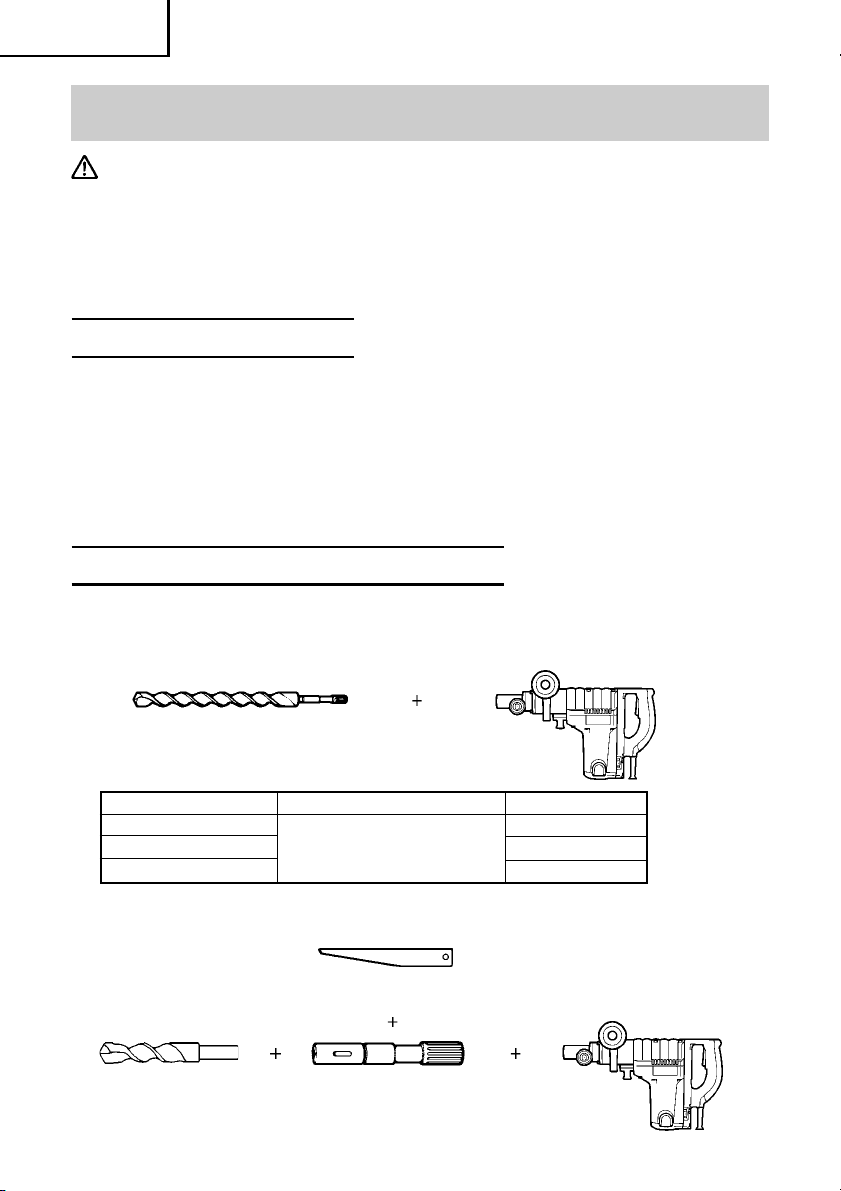
1. Through-hole drilling (Rotation + Hammering)
(1) Drill bit (Spline shank)
External dia.
1/2" (12.7 mm)
1" (25.4 mm)
1-1/2" (38.1 mm)
2. Anchor hole drilling (Rotation + Hammering)
(3) Cotter (Code No. 944477)
(1) Drill bit
(Taper shank)
18
Overall length
16"(400 mm)
(2) Taper shank adaptor
(Spline shank)
Code No.
985374
985375
985376
Page 19

(2) Taper shank adaptor
A-taper
B-taper
Taper shank adaptor formed
A-taper or B-taper is provided as
optional accessory, but drill bit for
it is not provided
3. Large-dia. hole boring (Rotation + Hammering)
English
Code No. 985377
Code No. 985378
(Guide plate)
Code No.
985388
955169
(1) Center pin
Code No.
955165
(2) Core bit
External dia.
2" (50 mm)
4-1/8" (105 mm)
4. Crushing (Hammering)
(1) Bull point
Overall length Code No.
12" (300 mm) 985383
5. Groove digging and edging (Hammering)
(1) Cold chisel
Overall length Code No.
12" (300 mm) 985381
18" (460 mm) 985382
6. Asphalt cutting (Hammering)
(1) Cutter
Overall length Width Code No.
12" (300 mm)
1-1/2" (38 mm) 985384
2" (50 mm) 985385
7. Digging
(1) Scoop
Code No. 985386
(3) Core bit shank
(Spline shank)
8. Syringe (for chip removal)
Code No. 944575
NOTE:
Specifications are subject to change without any obligation on the part of the
HITACHI.
19
Page 20

Français
INFORMATIONS IMPORTANTES
Lire et comprendre toutes les instructions de fonctionnement, les précautions de
sécurité et les avertissements dans ce mode d’emploi avant d’utiliser ou d’entretenir
cet outil motorisé.
La plupart des accidents causés lors de l’utilisation ou de l’entretien de l’outil motorisé
proviennent d’un non respect des règles ou précautions de base de sécurité. Un
accident peut la plupart du temps être évité si l’on reconnaît une situation de danger
potentiel avant qu’elle ne se produise, et en observant les procédures de sécurité
appropriées.
Les précautions de base de sécurité sont mises en évidence dans la section
“SECURITE” de ce mode d’emploi et dans les sections qui contiennent les
instructions de fonctionnement et d’entretien.
Les dangers qui doivent être évités pour prévenir des blessures corporelles ou un
endommagement de la machine sont identifiés par AVERTISSEMENTS sur l’outil
motorisé et dans ce mode d’emploi.
Ne jamais utiliser cet outil motorisé d’une manière qui n’est pas spécifiquement
recommandée par HITACHI sans avoir d’abord vérifié que l’utilisation prévue est
sans danger pour vous et les autres.
SIGNIFICATION DES MOTS D’AVERTISSEMENT
AVERTISSEMENT indique des situations potentiellement dangereuses qui, si elles
sont ignorées, pourraient entraîner de sérieuses blessures personnelles.
PRECAUTION indique des situations dangereuses qui, si elles sont ignorées, pourrait
entraîner de légères blessures personnelles ou endommager la machine.
REMARQUE met en relief des informations essentielles.
20
Page 21

SECURITE
REGLES GENERALE DE SECURITE
AVERTISSEMENT: Lire et coxmprendre toutes les instructions.
Un non respect de toutes les instructions ci-dessous peut
entraîner une électrocution, un incendie et/ou de
sérieuses blessures personnelles.
CONSERVER CES INSTRUCTIONS
1. Zone de travail
(1) Garder la zone de travail propre et bien éclairée. Les établis mal rangés et les
zones sombres invitent aux accidents.
(2) Ne pas utiliser les outils motorisés dans une atmosphère explosive, telle
qu’en présence de liquides inflammables, de gaz ou de poussières. Les outils
motorisés créent des étincelles qui risquent d’enflammer la poussière ou les
vapeurs.
(3) Tenir les spectateurs, les enfants et les visit eurs éloignés, lors de l’utilisation
de l’outil motorisé. Une distraction peut faire perdre le contrôle de la machine.
2. Sécurité électrique
(1) Les outils à double isolation sont équipés d’une fiche polarisée (une lame
est plus large que l’autre). Cette fiche ne pénétrera dans une prise secteur
polarisée que dans un sens. Si la fiche ne rentre pas complètement dans la
prise, la retourner. Si elle ne rentre toujours pas, contacter un électricien
qualifié pour installer une prise polarisée. Ne pas modifier la fiche d’aucune
façon. La double isolation élimine le besoin d’un cordon d’alimentation à
trois fils et d’un système d’alimentation avec mises à la terre.
(2) Eviter tout contact corporel avec les surfaces mises à la terre telles que les
canalisations, les radiateurs, les réchauds et les réfrigérateurs. Il y a un risque
accru d’électrocution si son corps est mis à la terre.
(3) Ne pas exposer les outils motorisés à la pluie ou à l’humidité. De l’eau
pénétrant à l’intérieur de l’outil motorisé augmente le risque d’électrocution.
(4) Ne pas maltraiter le cordon d’alimentation. Ne jamais utiliser le cordon pour
porter les outils ou tirer sur la fiche du réceptacle. Garder le cordon à l’écar t
de la chaleur, de l’huile, des arêt es coupant es ou des pièces en mouv ement.
Remplacer les cordons endommagés immédiatement. Des cordons
endommagés augmentent le risque d’électrocution.
(5) Lors de l’utilisation d’un outil motorisé, utiliser un cordon de rallonge
extérieur marqué “W -A ” ou “W”. Ces cordons sont prévus pour une utilisation
extérieure et réduisent les risques d’électrocution.
3. Sécurité personnelle
(1) Rester sur ses gardes, regarder ce que l’on fait et utiliser son sens commun
lors de l’utilisation d’un outil motorisé. Ne pas utiliser un outil en état de
fatigue ou sous l’influence de drogues, d’alcool ou de médicaments. Un
moment d’inattention lors de l’utilisation de l’outil motorisé peut entraîner
de sérieuses blessures personnelles.
Français
21
Page 22

Français
(2) S’habiller correctement. Ne pas porter des vêtements larges ou des bijoux.
Attacher les cheveux longs. Tenir ses cheveux, vêtements et ses gants
éloignés des parties mobiles. Les vêtements larges, les bijoux et les c heveux
longs peuvent se prendre dans les parties mobiles.
(3) Eviter tout démarrage accidentel. S’assurer que le l’interrupteur
d’alimentation est sur la position d’arrêt avant de brancher la machine.
Transporter l’appareil avec les doigts sur l’interrupteur d’alimentation ou
brancher un outil avec l’interrupteur sur la position marche invite aux
accidents.
(4) Retirer les clefs d’ajustement ou les commutateurs avant de mettre l’outil
sous tension. Une clef qui est laissée attachée à une partie tournante de
l’outil peut provoquer une blessure personnelle.
(5) Ne pas trop présumer de ses forces. Garder en permanence une position et
un équilibre correct. Une position et un équilibre correct permettent un
meilleur contrôle de l’outil dans des situations inattendues.
(6) Utiliser un équipement de sécurité. Toujours porter des lunettes de
protection. Un masque à poussière, des chaussures de sécurité
antidérapantes, un chapeau dur et des bouchons d’oreille doivent être utilisés
dans les conditions appropriées.
4. Utilisation de l’outil et entretien
(1) Utiliser un étau ou toutes autres façons de fixer et maintenir la pièce à usiner
sur une plate-forme stable. Tenir la pièce avec la main ou contre son corps
est instable et peut conduire à une perte de contrôle de l’outil.
(2) Ne pas forcer sur l’outil. Utiliser l’outil correct pour l’application souhaitée.
L’outil correct réalisera un meilleur et plus sûr travail dans le domaine pour
lequel il a été conçu.
(3) Ne pas utiliser un outil s’il ne se met pas sous ou hors tension avec un
interrupteur. Un outil qui ne peut pas être commandé avec un interrupteur
est dangereux et doit être réparé.
(4) Déconnecter la fiche de la source d’alimentation avant de réaliser tout
ajustement, changement d’accessoires ou pour ranger l’outil. De telles
mesures de sécurité réduisent le risque que l’outil ne démarre
accidentellement.
(5) Ranger les outils inutilisés hors de la portée des enfants et des autres
personnes inexpérimentées. Les outils sont dangereux dans les mains de
personnes inexpérimentées.
(6) Conserver les outils avec soin. Garder les outils de coupe aiguisés et pr opres.
Des outils bien entretenus, avec des lames coupantes aiguisées risquent
moins de se gripper et sont plus faciles à contrôler.
(7) Vérifier les défauts d’alignement ou gr ippage des parties mobiles, les ruptur es
des pièces et toutes les autres conditions qui peuvent affecter le
fonctionnement des outils. En cas de dommage, faire réparer l’outil avant
de l’utiliser . Beaucoup d’accidents sont causés par des outils mal entretenus.
(8) Utiliser uniquement les accessoires recommandés par le fabricant pour le
modèle utilisé. Des accessoires qui peuvent convenir à un outil, peuvent
devenir dangereux lorsqu’ils sont utilisés avec un autre outil.
22
Page 23

Français
5. Réparation
(1) La réparation de l’outil ne doit être réalisée uniquement par un réparateur
qualifié. Une réparation ou un entretien réalisé par un personnel non qualifié
peut entraîner des risques de blessures.
(2) Lors de la réparation d’un outil, utiliser uniquement des pièces de rechange
identiques. Suivre les instructions de la section d’entretien de ce mode
d’emploi. L’utilisation de pièces non autorisées ou un non respect des
instructions d’entretien peut créer un risque d’électrocution ou de blessures.
6. Ne jamais toucher les parties mobiles.
Ne jamais placer ses mains, ses doigts ou toute autre partie de son corps près
des parties mobiles de l’outil.
7. Ne jamais utiliser l’outil sans que tous les dispositifs de sécurité ne soient en
place.
Ne jamais faire fonctionner cet outil sans que tous les dispositifs et
caractéristiques de sécurité ne soient en place et en état de fonctionnement. Si
un entretien ou une réparation nécessite le retrait d’un dispositif ou d’une
caractéristique de sécurité, s’assurer de bien remettre en place le dispositif ou la
caractéristique de sécurité avant de recommencer à utiliser l’outil.
8. Utiliser l’outil correct
Ne pas forcer sur un petit outil ou accessoire pour faire le travail d’un outil de
grande puissance. Ne pas utiliser un outil pour un usage pour lequel il n’a pas
été prévu: par exemple, ne pas utiliser une scie circulaire pour couper des
branches d’arbre ou des bûches.
9. Ne jamais utiliser un outil motorisé pour des applications autres que celles
spécifiées.
Ne jamais utiliser un outil motorisé pour des applications autres que celles
spécifiées dans le mode d’emploi.
10.Manipuler l’outil correctement
Utiliser l’outil de la façon indiquée dans ce mode d’emploi. Ne pas laisser tomber
ou lancer l’outil. Ne jamais permettre que l’outil soit utilisé par des enfants, des
personnes non familiarisées avec son fonctionnement ou un personnel non
autorisé.
11.Maintenir toutes les vis, tous les boulons et les couvercles fermement en place.
Maintenir toutes les vis, tous les boulons et les couvercles fermement montés.
Vérifier leurs conditions périodiquement.
12.Ne pas utiliser les outils motorisés si le revêtement de plastique ou la poignée
est fendu.
Des fentes dans le revêtement ou la poignée peuvent entraîner une électrocution.
De tels outils ne doivent pas être utilisés avant d’être réparé.
13.Les lames et les accessoires doivent être fermement montés sur l’outil.
Eviter les blessures potentielles personnelles et aux autres. Les lames, les
instruments de coupe et les accessoires qui ont été montés sur l’outil doivent
être fixés et serrés fermement.
14.Garder propres les évents d’air du moteur
Les évents d’air du moteur doivent être maintenus propres de façon que l’air
puisse circuler librement tout le temps. Vérifier les accumulations de poussière
fréquemment.
23
Page 24

Français
15.Utiliser l’outil motorisé à la tension nominale.
Utiliser l’outil motorisé à la tension spécifiée sur sa plaque signalétique.
Si l’on utilise l’outil motorisé avec une tension supérieure à la tension nominale,
il en résultera une rotation anormalement trop rapide du moteur et cela risque
d’endommager l’outil et le moteur risque de griller.
16.Ne jamais utiliser un outil défectueux ou qui fonctionne anormalement.
Si l’outil n’a pas l’air de fonctionner normalement, fait des bruits étranges ou
sans cela paraît défectueux, arrêter de l’utiliser immédiatement et le faire réparer
par un centre de service Hitachi autorisé.
17.Ne jamais laisser fonctionner l’outil sans surveillance. Le mettre hors tension.
Ne pas abandonner l’outil avant qu’il ne soit complètement arrêté.
18.Manipuler l’outil motorisé avec précaution.
Si un outil motorisé tombe ou frappe un matériau dur accidentellement, il risque
d’être déformé, fendu ou endommagé.
19.Ne pas essuyer les parties en plastique avec du solvant.
Les solvants comme l’essence, les diluants, la benzine, le tétrachlorure de carbone
et l’alcool peuvent endommager et fissurer les parties en plastique. Ne pas les
essuyer avec de tels solvants.
Essuyer les parties en plastique avec un chiffon doux légèrement imbibé d’une
solution d’eau savonneuse et sécher minutieusement.
REGLES DE SECURITE SPECIFIQUES ET SYMBOLES
1. Tenir les outils par les surfaces de grippag e lors de la réalisation d’opér ation où
l’outil de coupe risque d’entrer en contact avec des câbles cachés ou son propre
cordon. Un contact avec un fil “sous tension” mettra les parties métalliques de
l’outil “sous tension” et électrocutera l’utilisateur.
2. Porter des bouchons d’oreille lors de l’utilisation de l’outil pendant de longues
périodes. Une exposition prolongée à un son de forte intensité peut endommager
l’ouïe de l’utilisateur.
3. NE JAMAIS toucher la mèche avec des mains nues tout de suite après l’utilisation.
4. NE JAMAIS porter de gants faits de matériaux susceptibles de s’ef filocher , comme
du coton, de la laine, de la toile ou de la ficelle, etc.
5. TOUJOURS fixer la poignée latérale et tenir fermement le marteau rotatif.
6. TOUJOURS faire attention aux objets dissimulés, par exemple des fils électriques.
Le fait de toucher un câblage ou un fil électrique avec l’outil risque de provoquer
un choc électrique.
Vérifier qu’il n’y a pas d’objets, par exemple des fils électriques, dissimulés dans
le mur, le plancher ou le plafond sur lesquels on doit travailler.
7. Définitions pour les symboles utilisés sur cet outil
V .............volts
Hz ........... hertz
A............. ampères
no ..........vitesse sans charge
............Construction de classe II
---/min .... tours par minute
24
Page 25

Français
DOUBLE ISOLATION POUR UN FONCTIONNEMENT PLUS SUR
Pour assurer un fonctionnement plus sûr de cet outil motorisé, HITACHI a adopté
une conception à double insolation. “Double isolation” signifie que deux systèmes
d’isolation physiquement séparés ont été utilisés pour isoler les matériaux
conducteurs d’électricité connectés à l’outil motorisé à partir du cadre extérieur
manipulé par l’utilisateur. C’est pourquoi, le symbole “ ” ou les mots “Double
insulation” (double isolation) apparaissent sur l’outil motorisé ou sur la plaque
signalétique.
Bien que ce système n’ait pas de mise à terre extérieure, il est quand même
nécessaire de suivre les précautions de sécurité électrique données dans ce mode
d’emploi, y-compris de ne pas utiliser l’outil motorisé dans un environnement
humide.
Pour garder le système de double isolation effectif, suivre ces précautions:
䡬 Seuls les CENTRES DE SERVICE AUTORISES HITACHI peuvent démonter et
remonter cet outil motorisé et uniquement des pièces de rechange HITACHI
garanties d’origine doivent être utilisées.
䡬 Nettoyer l’extérieur de l’outil motorisé uniquement avec un chiffon doux
légèrement imbibé d’une solution savonneuse et essuyer minutieusement.
Ne jamais utiliser des solvants, de l’essence ou des diluants sur les parties en
plastique; sinon le plastique risquerait de se dissoudre.
CONSERVER CES INSTRUCTIONS
ET
LES METTRE A LA DISPOSITION
DES AUTRES UTILISATEURS
DE CET OUTIL!
25
Page 26

Français
DESCRIPTION FONCTIONNELLE
REMARQUE:
Les informations contenues dans ce mode d’emploi sont conçues pour assister
l’utilisateur dans une utilisation sans danger et un entretien de l’outil motorisé.
Certaines illustrations dans ce mode d’emploi peuvent montrer des détails ou
des accessoires différents de ceux de l’outil motorisé utilisé.
NOM DES PARTIES
Quenouille
Porte-outil
Vis de fixation
(Sous le couvercle de queue)
Sélecteur
Couvercle de queue
Poignée latérale
Carter
Fig. 1
Interrupteur
Poignée
Plaque
signalétique
Molette
Bouchon de charbon
(À l’intérieur du
couvercle de queue)
SPECIFICATIONS
Moteur Moteur série monophasé à collecteur
Source d’alimentation Secteur, 115 V 60 Hz, monophasé
Courant 8,7 A
Capacité Mèche: 1-9/16" (40 mm)
Couronne: 4-1/8" (105 mm)
Vitesse sans charge 180 – 360/min.
Vitesse de percussion à pleine charge 1400 – 2800 bpm
Poids 15 lbs (6,8 kg)
26
Page 27

Français
ASSEMBLAGE ET FONCTIONNEMENT
APPLICATIONS
Fonction de rotation et de percussion
䡬 Perçage de trous d’ancrage
䡬 Perçage de trous dans béton
Fonction de percussion uniquement
䡬 Broyage du béton, burinage, creusage et équarrissage (par application des
accessoires optionnels)
AVANT L’UTILISATION
1. Source d’alimentation
S’assurer que la source d’alimentation qui doit être utilisée est conforme à la
source d’alimentation requise spécifiée sur la plaque signalétique du produit.
2. Interrupteur d’alimentation
S’assurer que l’interrupteur est sur la position OFF (arrêt). Si la fiche est connectée
sur une prise alors que l’interrupteur est sur la position ON (marche), l’outil
motorisé démarrera immédiatement risquant de causer de sérieuses blessures.
3. Cordon prolongateur
Quand la zone de travail est éloignée de la source d’alimentation, utiliser un
cordon prolongateur d’épaisseur et de capacité nominale suffisante. Le cordon
prolongateur doit être aussi court que possible.
AVERTISSEMENT: T out cordon endommagé devra êtr e remplacé ou réparé.
4. Vérifier la prise
Si la prise reçoit la fiche avec beaucoup de jeu, elle doit être réparée. Contacter
un électricien licencié pour réaliser les réparations nécessaires.
Si une telle prise défectueuse est utilisée, elle peut causer une surchauffe
entraînant des dangers sérieux.
5. Vérification des conditions d’environnement
Vérifier que l’état de l’aire de travail est conforme aux précautions.
6. Comment installer le cache-poussière (Fig. 2)
T oujours installer le cache-poussière sur
le raccord de la queue conique.
Insérer le cache-poussière bien à fleur
de la rainure.
REMARQUE:
Pour une mèche épaisse, insérer le
cache-poussière par l'arrière de la
mèche.
Cachepoussière
Insérer jusqu’à la rainure
Fig. 2
27
Page 28

Français
7. Comment installer l’outil
PRECAUTION: Pour les outils tels que foret et pointe de broyage n’utiliser que
les pièces HITACHI authentiques.
(1) Nettoyer, puis graisser la queue de l’outil
avec la graisse fournie à cet effet en tube
vert.
(2) Tirer le porte-outil dans la direction de
la flèche 1 et le tourner dans la direction
de la flèche 2 (sens antihoraire). Insérer
à fond la queue de l'outil dans le trou
hexagonal du couvercle frontal. (Fig. 3)
(3) Retourner le porte-outil pour fixer l'outil.
REMARQUE:
Pour enlever l'outil procéder à l'inverse
de son installation.
Couvercle frontal
Queue
Porte-outil
Fig. 3
2
1
8. Réglage du nombre de rotations et
de percussion (Fig. 4)
Ce marteau rotatif est équipé d’un circuit
de commande électronique incorporé
capable d’ajuster et de réguler le
nombre de rotations et la fréquence de
percussion. Pour l’utiliser , régler la bague
en fonction du travail, par exemple
perçage d’orifices dans des matériaux
fragiles, burinage, centrage, etc.
La graduation ”1” de la bague représente la vitesse minimum, avec 180 rotations
par minute et 1400 percussions par minute. La graduation ”5” de la bague
représente la vitesse maximum, avec 360 rotations par minute et 2800
percussions par minute.
Fig. 4
Molette
PRECAUTION:
Ne pas régler la bague pendant le fonctionnement. Cela pourrait provoquer des
blessures du fait que la perceuse n’est plus tenue que d’une seule main, ce qui
empêche un contrôle solide de la perceuse.
UTILISATION
1. Comment percer des trous (Fig. 5)
(1) Tirer l’interrupteur après avoir appliqué
la pointe de la mèche à la position de
forage.
Fig. 5
28
Page 29

Français
(2) Il n’est pas nécessaire d’appuyer de force sur le corps du marteau rotatif. Il sera
suffisant d’appuyer légèrement sur le marteau rotatif jusqu’à ce que les éclats
soient déchargés librement.
PRECAUTION:
Bien que cette machine soit équipée d’un cran de sécurité, si la mèche est prise
dans le béton ou autre matériel l’arrêt de son fonctionnement pourrait faire
tourner le corps de la machine. Tenir fermement la poignée principale et la
poignée latérale pendant le fonctionnement.
2. Comment buriner ou broyer (Fig. 6)
En appliquant l'outil sur la position de
burinage ou de broyage, faire
fonctionner le marteau rotatif en utilisant
son propre poids. Il n’est pas nécessaire
d’appuyer ou de pousser de force.
3. Comment sélectionner rotationpercussion et percussion
(1) Rotation-percussion (Fig. 7)
Faire tourner le sélecteur dans le sens
des aiguilles d’une montre, de façon que
le repère ▲ du sélecteur soit aligné sur
le repère ▲ situé à côté du repère
du cache inférieur.
(2) Percussion (Fig. 8)
Faire tourner le sélecteur dans le sens
inverse des aiguilles d’une montre, de
façon que le repère ▲ du sélecteur soit
aligné sur le repère ▲ situé à côté du
repère du cache inférieur.
Sélecteur
PRECAUTION:
䡬 Le fait de tourner le sélecteur pendant
que le moteur tourne entraînera la
rotation accidentelle de l’outil. Le
sélecteur ne doit être tourné que
lorsque le moteur est à l’arrêt.
Fig. 6
Cache inférieur
▲
▲
Fig. 7
Cache inférieur
▲
▲
Sélecteur
Fig. 8
29
Page 30

Français
4. Installer la quenouille (Fig. 9)
(1) Desserrer la poignée latérale et insérer
la partie droite de la quenouille dans le
trou du boulon de la poignée.
(2) Déplacer la quenouille à la position
spécifiée et faire tourner l’attache
coulissante de la poignée latérale dans
le sens des aiguilles d’une montre pour
fixer la quenouille.
5. Préchauffage (Fig. 10)
Le système de graissage de l’outil risque
de devoir être préchauffé dans les
régions froides.
Placer l’extrémité de la mèche de façon
qu’elle entre en contact avec le béton,
enclencher l’interrupteur et effectuer
une opération de préchauffage. Bien
s’assurer que l’outil fait entendre un
bruit de heurt, puis utiliser l’outil.
PRECAUTIÓN:
Pendant l’opération de préchauffage,
tenir fermement la poignée latérale et
le corps de l’outil des deux mains de
façon à garder une bonne prise de l’outil
et faire attention que le corps de
l’opérateur ne pivote pas sons l’effet
d’une mèche coincée.
Quenouílle
Poignée latérale
Fig. 9
Fig. 10
Raccord de
queue coníque
Mèche
(Queue conique)
6. Comment utiliser la mèche (queue
conique) et le raccord de queue
conique.
(1) Installer la mèche à queue conique dans
le raccord de queue conique.
(2) Mettre l’appareil sous tension et percer
un trou de base.
(3) Après avoir retirer la poussière avec une
seringue, fixer le mandrin à la pointe du
sabot et l’enfoncer dans le sabot avec
un marteau.
(4) Pour retirer la mèche à queue conique,
insérer une clavette dans la fente du
raccord de queue conique et frapper sur
la clavette avec un marteau. (Fig. 12)
30
Clavette
Fig. 11
Raccord de
queue conique
Support
Fig. 12
Page 31

COMMENT UTILISER LA COURONNE
Français
Utiliser la couronne pour percer de grands
trous.
L’utiliser avec le goujon central et la queue
de couronne fournis en tant qu’accessoires
en option.
1. Montage
PRECAUTION:
S’assurer que l’interrupteur est sur la
position d’arrêt (OFF) et débrancher
l’outil.
(1) Monter la couronne sur la queue de
couronne. (Fig. 13)
Graisser le filetage da la queue de
couronne afin de faciliter le démontage.
(2) Monter la queue de couronne sur le
marteau rotatif à percussion. (Fig. 14)
(3) Introduire la guijon central dans la
plaque de guidage jusqu’à ce qu’il
arrête.
(4) Engager la plaque de guidage dans la
couronne et tourner la plaque de
guidage à gauche ou à droite de
manière à ce qu’elle à ce qu’elle ne
puisse pas tomber, même si elle
orientée vers le bas. (Fig. 15)
2. Perçage (Fig. 16)
(1) Brancher la perceuse.
(2) Un ressort est placé dans le goujon
central.
Appuyer légèrement l’outil contre le
mur ou le plancher tout droit. Toute la
surface de la couronne doit être en
contact avec le mur ou le plancher.
Mettre en marche.
(3) Quand on a percé sur une profondeur
d’environ 3/16" (5 mm), la position du
trou est déterminée. Continuer à percer
après avoir retiré le goujon central et la
plaque de guidage de la couronne.
Couronne
Goujon
central
Couronne
Queue de
couronna
Fig. 13
Fig. 14
Plaque de
guidage
Bout de
couronne
Fig. 15
Fig. 16
31
Page 32

Français
(4) Si l’on applique une force excessive, cela donnera un travail bâclé et abîmera la
pointe du foret de perçage, réduisant ainsi la durée de service du marteau rotatif.
PRECAUTION:
Quand on retire le goujon central et la plaque de guidage, mettre l’interrupteur
sur la position d’arrêt (OFF) et débrancher la perceuse.
3. Démontage (Fig. 17)
Une autre méthode consiste à retirer la
queue de la couronne du marteau rotatif
à frapper fortement la tête de la queue
de la couronne deux ou trois fois avec
un marteau, tout en maintenant la
couronne. Cela aura pour effet de
desserrer le filetage et on pourra retirer
la couronne.
Queue de
couronne
Fig. 17
32
Page 33

ENTRETIEN ET INSPECTION
AVERTISSEMENT: S’assurer de mettre l’interrupteur d’alimentation sur la
position OFF et de déconnecter la fiche de la prise secteur
avant l’entretien et l’inspectio.
1. Contrôle du foret de perçage
Etant donné que l’utilisation d’une mèche usée entraînera un mauvais
fonctionnement du moteur et une diminution de l’efficacité, remplacez la mèche
usée par une neuve ou aiguisez-la immédiatement et dès que vous notez une
certaine usure.
2. Inspection des vis de montage
Inspecter régulièrement toutes les vis de montage et s’assurer qu’elles sont
correctement serrées. Si l’une des vis était desserrée, la resserrer immédiatement.
AVERTISSEMENT: Utiliser la marteau rotatif avec des vis desserrées est
extrêmement dangereux.
3. Entretien du moteur:
Le bobinage de l’ensemble moteur est le “coeur” même de l’outil électro-portatif.
V eiller soigneusement à ce que ce bobinage ne soit pas endommagé et/ou mouillé
par de l’huile ou de l’eau.
4. Contrôle des balais en carbone (Fig. 18)
Le moteur utilise des balais en carbone qui sont des pièces qui s’usent. Quand
ils sont usés ou près de la “limite d’usure”, il pourra en résulter un mauvais
fonctionnement du moteur.
Quand le moteur est équipé d’un balai en carbone à arrêt automatique, il s’arrêtera
automatiquement. Remplacez alor les balais en carbone par des nouveaux et
ayant les mêmes numéros que ceux montré sur la figure. En outre, toujours
tenir les balais propres et veiller à ce qu’ils coulissent librement dans les supports.
Français
PRECAUTION: Utiliser la polisseuse avec un balai en carbone qui est usé au-
delà de la limite d’usure endommagera le moterur.
Limite d’usure
No. du balai en carbone
73
0,28" (7 mm)
0,67" (17 mm)
Fig. 18
REMARQUE: Utiliser le balai en carbone HITACHI No. 73 indiqué sur la Fig. 18.
33
Page 34

Français
䡬 Remplacement du balais en carbone
Desserrer la vis de fixation et enlever le couvercle de la queue. Enlever la chapeau
de balai et la balai en carbone. Après avoir remplacé le balai en carbone, serrer
fermement le chapeau du balai et installer le couvercle avec deux vis de fixation.
5. Comment remplacer la graisse
Cette machine est de contruction entièrement hermétique pour la protéger contre
la poussière et pour éviter les fuites de lubrifiant. Elle peut donc être utilisée
sans lubrification pendant longtemps. Remplacer la graisse comme indiqué cidessous.
䡬 Période de remplacement
Remplacer la graisse après chaque période de 6 moins d’utilisation. Se procurer
la graisse chez l’Agence de Service Autorisée HITACHI la plus proche. Procéder
au remplacement.
䡬 Plein de graisse
PRECAUTION: Avant de faire le plein de la graisse, fermer l’interrupteur et
débrancher l’outil de la prise de courant.
(1) Enlever le couvercle du carter et essuyer
la graisse à l’intérieur.
(2) Appliquer 0,7 oz (20 g) de graisse pour
marteau électrique Hitachi A (en tube)
au carter.
Etant donné que le tube contient 1,0 oz
(30 g) de graisse, appliquer 2/3 du
contenu.
(3) Après avoir fait le plein de graisse,
installer fermement le couvercle du
carter.
REMARQUE:
La graisse pour marteau électrique Hitachi A est du type à viscosité faible. Si
nécessaire, se procurer la graisse chez un agent réparateur Hitachi agréé;
adressez-vous à votre Agent de Service Autorisé Hitachi pour vous en procurer
de nouveau.
Cache de carter
Fig. 19
6. Entretien et reparation
Tous les outils motorisés de qualité auront éventuellement besoin d’une
réparation ou du remplacement d’une pièce à cause de l’usure normale de l’outil.
Pour assurer que seules des pièces de rechange autorisées seront utilisées, tous
les entretiens et les réparations doivent être effectués uniquement par UN
CENTRE DE SERVICE HITACHI AUTORISE.
34
Page 35

Français
ACCESSOIRES
AVERTISSEMENT: Les accessoires pour cet outil motorisé sont mentionnés
dans ce mode d’emploi.
L’utilisation de tout autre attachement ou accessoire
peut être dangereux et peut causer des blessures ou des
dommages mécaniques.
REMARQUE:
Les accessoires sont sujets à changement sans obligation de la part de HITACHI.
ACCESSOIRES STANDARD
(1) Valise (Plastique) (No. de code 313097)................................................................ 1
(2) Poignée latérale (No. de code 313078) ................................................................. 1
(3) Quenouille (No. de code 971786) .......................................................................... 1
(4) Clé allen 4 mm (No. de code 944458) ................................................................... 1
(5) Clé allen 5 mm (No. de code 944459) ................................................................... 1
(6) Graisse A pour marteau (No. de code 981840) .................................................... 1
(7) Cache-poussière (No. de code 993245) ................................................................ 1
ACCESSOIRES SUR OPTION.....vendus séparément
Pour plus d’informations sur les accessoires, veuillez contacter HIT ACHI 1-800-59-TOOLS
1. Perçage de trous de passage (rotation + percussion)
(1) Mèche (queue cannelée)
Diamètre extérieur
1/2" (12.7 mm)
1" (25.4 mm)
1-1/2" (38.1 mm)
2. Perçage de trous d’ancrage (rotation + percussion)
(3) Clavette (No. de code 944477)
(1) Mèche
(queue conique)
Longueur totale
16"(400 mm)
(2) Raccord de queue conique
(queue cannelée)
No. de code
985374
985375
985376
35
Page 36

Français
(2) Raccord de queue conique
Cône-A
Cône-B
La raccord de queue conique en
forme cône-A ou cône-B est fourni en
tant qu’accessoire sur option, mais la
mèche correspondante n’est par fournie.
3. Perçage de trous à large diamètre (Rotation + Percussion)
No. de code 985377
No. de code 985378
(plaque de
guidage)
No. de code
985388
955169
(1) Goujon
central
No. de code
955165
(2) Couronne
Diamètre extérieur
2" (50 mm)
4-1/8" (105 mm)
(3) Queue de cournne
(queue cannelée)
4. Broyage (Percussion)
(1) Point de broyage
Longueur totale No. de code
12" (300 mm) 985383
5. Creusage de rainures et cassure des angles (Percussion)
(1) Ciseau à froid
Longueur totale No. de code
12" (300 mm) 985381
18" (460 mm) 985382
6. Coupage d’asphalte (Percussion)
(1) Fraise
Longueur totale Largeur No. de code
12" (300 mm)
1-1/2" (38 mm) 985384
2" (50 mm) 985385
7. Puisage (Percussion)
(1) Bourroir
No. de code 985386
8. Seringue (pour enlever déchets)
No. de code 944575
REMARQUE:
Les spécifications sont sujettes à modification sans aucune obligation de la part de
HITACHI.
36
Page 37

Español
INFORMACIÓN IMPORTANTE
Antes de utilizar o realizar cualquier trabajo de mantenimiento de esta herramienta
eléctrica, lea y comprenda todas las instrucciones de operación, las precauciones
de seguridad, y las advertencias de este Manual de instrucciones.
La mayoría de los accidentes producidos en la operación y el mantenimiento de
una herramienta eléctrica se deben a la falta de observación de las normas o
precauciones de seguridad. Los accidentes normalmente podrán evitarse
reconociendo una situación potencialmente peligrosa a tiempo y siguiendo los
procedimientos de seguridad apropiados.
Las precauciones básicas de seguridad se describen en la sección “SEGURIDAD”
de este Manual de instrucciones y en las secciones que contienen las instrucciones
de operación y mantenimiento.
Para evitar lesiones o el daño de la herramienta eléctrica, los riesgos están
identificados con ADVERTENCIAS en dicha herramienta y en este Manual de
instrucciones.
No utilice nunca esta herramienta eléctrica de ninguna forma no específicamente
recomendada por HITA CHI a menos que usted se haya asegurado de que la utilización
planeada será segura para usted y otras personas.
SIGNIFICADO DE LAS PALABRAS DE SEÑALIZACIÓN
ADVERTENCIA indica situaciones potencialmente peligrosas que, si se ignoran,
pueden resultar en lesiones serias.
PRECAUCIÓN indica situaciones potencialmente peligrosas que, si se ignoran,
pueden resultar en lesiones moderadas, o que pueden causar averías en la
herramienta eléctrica.
NOTA acentúa información esencial.
37
Page 38

Español
SEGURIDAD
NORMAS GENERALES DE SEGURIDAD
ADVERTENCIA: Lea y entienda todas las instrucciones.
Si no sigue las instrucciones indicadas a continuación,
pueden producirse descargas eléctricas, incendios, y/o
lesiones serias.
GUARDE ESTAS INSTRUCCIONES.
1. Área de trabajo
(1) Mantenga el área de trabajo limpia y bien iluminada. Los bancos de trabajo
desordenados y las áreas obscuras pueden conducir a accidentes.
(2) No utilice la herramienta en atmósferas explosivas, como en presencia de
líquidos inflamables, gases, o polvo. La herramienta eléctrica crea chispas
que pueden incendiar polvo o gases.
(3) Mantenga alejadas a otras personas, niños o visitantes, cuando utilice la
herramienta eléctrica. Las distracciones pueden hacer que pierda el control
de la herramienta.
2. Seguridad eléctrica
(1) Las herramientas eléctricas con aislamiento doble poseen un enchufe
polarizado (una cuchilla es más ancha que la otra.) Este enchufe encajará en
un tomacorriente polarizado de una sola forma. Si el enchufe no entra
completamente en el tomacorriente, invierta su sentido de inserción. Si
sigue sin entrar, póngase en contacto con un electricista cualificado para
que le instale un tomacorriente polarizado. No cambie nunca el enchufe. El
aislamiento doble elimina la necesidad de un cable de alimentación de
tres conductores, uno para puesta a tierra, y del sistema de alimentación con
puesta a tierra.
(2) Evite el contacto con superficies con puesta a tierra, tales como tubos,
radiadores, hornos, y refrigeradores. Si toca tierra, existe el peligro de que
reciba una descarga eléctrica.
(3) No exponga la herramienta eléctrica a la lluvia ni a la humedad. La entrada
de agua en la herramienta eléctrica aumentará el riesgos de descargas
eléctricas.
(4) No maltrate el cable de alimentación. No utilice nunca el cable de
alimentación para transportar la herramienta ni para desconectarla del
tomacorr iente. Mant enga el cable alejado del calor, aceite, bordes cortant es,
o partes móviles. Reemplace inmediatament e cualquier cable dañado. Un
cable dañado puede ser la causa de descargas eléctricas.
(5) Cuando utilice la herramienta eléctrica en exteriores, utilice un cable
prolongador marcado con “W-A” o “W”. Estos cables han sido diseñados
para utilizarse en exteriores y reducir el riesgo de descargas eléctricas.
3. Seguridad personal
(1) Esté siempre alerta y utilice el sentido común cuando utilice la herramienta
eléctrica. No utilice la herramienta cuando esté cansado o bajo la influencia
38
Page 39

de medicamentos ni de alcohol. Un descuido al utilizar la herramienta
eléctrica puede resultar en una lesión seria.
(2) Vístase adecuadamente. No utilice ropa floja ni joyas. Si tiene pelo largo,
recójaselo. Mant enga su pelo, ropa, y guant es alejados de las partes móviles.
La ropa floja, las joyas, o el pelo largo pueden engancharse en las partes
móviles.
(3) Evite la puesta en marcha accidental. Cerciórese de que la alimentación de
la herramienta eléctrica esté desconectada antes de enchufarla en una toma
de la red. Si lleva la herramienta eléctrica con el dedo colocado en el
interruptor, o si la enchufa con dicho interruptor cerrado, es posible que se
produzcan accidentes.
(4) Quite las llaves de ajuste y abra los interruptores antes de poner en
funcionamiento la herramienta. Una llave dejada en una parte móvil de la
herramienta podría resultar en lesiones.
(5) No sobrepase su alcance. Mantenga en todo momento un buen equilibrio.
El conservar en todo momento el equilibrio le permitirá controlar mejor la
herramienta en situaciones inesperadas.
(6) Utilice equipos de seguridad. Póngase siempre gafas protectoras. Para
conseguir las condiciones apropiadas, utilice una mascarilla contra el polvo,
zapatos no resbaladizos, un casco duro, y tapones para los oídos.
4. Utilización y cuidados de la herramienta
(1) Utilice abrazaderas u otra forma práctica de asegurar y sujetar la pieza de
trabajo sobre una plataforma estable. La sujeción de la pieza de trabajo con
la mano o contra su cuerpo puede ser inestable y conducir a la pérdida del
control.
(2) No fuerce la herramienta. Utilice la herramienta correcta para su aplicación.
Con la herramienta correcta realizará mejor el trabajo y ésta será más segura
para la velocidad para la que ha sido diseñada.
(3) No utilice la herramienta si el interruptor de alimentación de la misma no
funciona. Cualquier herramienta que no pueda controlarse con el interruptor
de alimentación puede resultar peligrosa, y deberá repararse.
(4) Desconecte el enchufe del cable de alimentación antes de realizar cualquier
ajuste, cambiar accesorios, o guardar la herramienta. Tales medidas
preventivas de seguridad reducirán el riesgo de que la herramienta se ponga
en funcionamiento accidentalmente.
(5) Guarde las herramientas que no vaya a utilizar fuera del alcance de niños y
de otras personas no entrenadas. Las herramientas son peligrosas en manos
de personas inexpertas.
(6) Realice el mantenimiento cuidadoso de las herramientas. Mantenga las
herramientas afiladas y limpias. Las herramientas adecuadamente
mantenidas, con los bordes cortantes afilados, serán más fáciles de utilizar y
controlar.
(7) Compruebe que las piezas móviles no estén desalineadas ni atascadas, que
no haya piezas rotas, y demás condiciones que puedan afectar la operación
de las herramientas. En caso de que una herramienta esté averiada, repárela
antes de utilizarla. Muchos de los accidentes se deben a herramientas mal
cuidadas.
(8) Utilice solamente los accesorios recomendados por el fabricante para su
modelo. Los accesorios adecuados para una herramienta pueden ser
peligrosos cuando se utilicen con otra.
Español
39
Page 40

Español
5. Servicio de reparación
(1) El servicio de reparación deberá realizarlo solamente personal cualificado.
El servicio de mantenimiento o de reparación realizado por personal no
cualificado podría resultar en el riesgo de lesiones.
(2) Para el servicio de mantenimiento o reparación de una herramienta, utilice
solamente piezas de repuesto idénticas. Siga las instrucciones de la sección
de mantenimiento de este manual. La utilización de piezas no autorizadas, o
el no seguir las indicaciones del Manual de instrucciones puede crear el riesgo
de descargas eléctricas u otras lesiones.
6. No toque nunca las piezas móviles.
No coloque nunca sus manos, dedos, ni demás partes del cuerpo cerca de las
piezas móviles de la herramienta.
7. No utilice nunca la herramienta sin los protectores colocados en su lugar.
No utilice nunca esta herramienta sin los protectores de seguridad correctamente
instalados. Si el trabajo de mantenimiento o de reparación requiere el desmontaje
de un protector de seguridad, cerciórese de volver a instalarlo antes de utilizar
la herramienta.
8. Utilice la herramienta correcta.
No fuerce herramientas ni accesorios pequeños para realizar un trabajo pesado.
No utilice las herramientas para fines no proyectados, por ejemplo, no utilice
esta amoladora angular para cortar madera.
9. No utilice nunca una herramienta eléctrica para aplicaciones que no sean las
especificadas.
No utilice nunca una herramienta eléctrica para aplicaciones no especificadas
en este Manual de instrucciones.
10.Maneje correctamente la herramienta.
Maneje la herramienta de acuerdo con las instrucciones ofrecidas aquí. No deje
caer ni tire la herramienta. No permita nunca que los niños ni otras personas no
autorizadas ni familiarizadas con la operación de la herramienta utilicen ésta.
11.Mantenga todos los tornillos, pernos, y cubiertas firmemente fijados en su lugar.
Mantenga todos los tornillos, pernos, y cubiertas firmemente montados.
Compruebe periódicamente su condición.
12. No utilice herramientas eléctricas si la carcasa o la empuñadura de plástico
está rajada.
Las rajas en la carcasa o en la empuñadura de plástico pueden conducir a
descargas eléctricas. Tales herramientas no deberán utilizarse mientras no se
hayan reparado.
13. Las cuchillas y los accesorios deberán montarse con seguridad en la herramienta.
Evite lesiones personales y de otras personas. Las cuchillas, los accesorios de
corte, y demás accesorios montados en la herramienta deberán fijarse con
seguridad.
14.Mantenga limpio el conducto de ventilación del motor.
El conducto de ventilación del motor limpio para que el aire pueda circular
libremente en todo momento. Compruebe frecuentemente y limpie el polvo
acumulado.
15.Utilice las herramientas eléctricas con la tensión de alimentación nominal.
Utilice las herramientas eléctricas con las tensiones indicadas en sus placas de
características.
40
Page 41

Español
La utilización e una herramienta eléctrica con una tensión superior a la nominal
podría resultar en revoluciones anormalmente altas del motor, en el daño de la
herramienta, y en la quemadura del motor.
16.No utilice nunca una herramienta defectuosa o que funcione anormalmente.
Si la herramienta parece que funciona anormalmente, produciendo ruidos
extraños, etc., deje inmediatamente de utilizarla y solicite su arreglo a un centro
de reparaciones autorizado por Hitachi.
17.No deje nunca la herramienta en funcionamiento desatendida. Desconecte su
alimentación.
No deje sola la herramientas hasta mientras no se haya parado completamente.
18.Maneje con cuidado las herramientas eléctricas.
Si una herramienta eléctrica se ha caído o ha chocado inadvertidamente contra
materiales duros, es posible que se haya deformado, rajado, o dañado.
19.No limpie las partes de plástico con disolvente.
Los disolventes, como gasolina, diluidor de pintura, bencina, tetracloruro de
carbono, y alcohol pueden dañar o rajar las partes de plástico. No las limpie con
tales disolventes.
Limpie las partes de plástico con un paño suave ligeramente humedecido en
agua jabonosa y después séquelas bien.
NORMAS Y SÍMBOLOS ESPECÍFICOS DE SEGURIDAD
1. Sujete las herramientas por las superficies de empuñadura aisladas cuando
realice una operación en la que la her ramienta de corte pueda entr ar en contacto
con cables ocultos o con su propio cable de alimentación. El contacto con un
conductor “activo” “activará” las partes metálicas de la herramienta y el operador
recibirá una descarga eléctrica.
2. Cuando tenga que utilizar la herramienta durante mucho tiempo, colóquese
tapones en los oídos. La exposición prolongada a ruido de gran intensidad
puede causar la pérdida del sentido del oído.
3. NUNCA toque la broca de la herramienta con las manos desnudas después de
la operación.
4. NUNCA utilice guantes de material que pueda enrollarse, como algodón, lana,
paño, cuerda, etc.
5. Fije SIEMPRE la empuñadura lateral y sujete con seguridad el martillo giratorio.
6. Tenga SIEMPRE cuidado con los objetos ocultos, tales como cables bajo tierra.
Si tocase estos cables activos con la herramienta, podría recibir una descarga
eléctrica.
Confirme que no haya objetos enterrados o empotrados tales como cables
eléctricos en la pared, el piso, o el techo donde vaya a trabajar.
7. Definiciones para los símbolos utilizados en esta herramienta.
V .............voltios
Hz ........... hertzios
A ............. amperios
no ..........velocidad sin carga
W ............ vatios
............Construcción de clase II
---/min ....revoluciones por minuto
41
Page 42

Español
AISLAMIENTO DOBLE PARA OFRECER UNA OPERACIÓN MÁS SEGURA
Para garantizar una operación más segura de esta herramienta eléctrica, HITACHI
ha adoptado un diseño de aislamiento doble. “Aislamiento doble” significa que se
han utilizado dos sistemas de aislamiento físicamente separados para aislar los
materiales eléctricamente conductores conectados a la fuente de alimentación del
bastidor exterior manejado por el operador. P or lo tanto, en la herramienta eléctrica
o en su placa de características aparecen el símbolo “ ” o las palabras “Double
insulation” (aislamiento doble).
Aunque este sistema no posee puesta a tierra externa, usted deberá seguir las
precauciones sobre seguridad eléctrica ofrecidas en este Manual de instrucciones,
incluyendo la no utilización de la herramienta eléctrica en ambientes húmedos.
para mantener efectivo el sistema de aislamiento doble, tenga en cuenta las
precauciones siguientes:
䡬 Esta herramienta eléctrica solamente deberá desensamblar y ensamblarla un
CENTRO DE REP ARA CIONES A UT ORIZADO POR HITACHI, y solamente deberán
utilizarse con ella piezas de reemplazo genuinas de HITACHI.
䡬 Limpie el exterior de la herramienta eléctrica solamente con un paño suave
humedecido en agua jabonosa, y después séquela bien.
No utilice disolventes, gasolina, ni diluidor de pintura para limpiar las partes de
plástico, ya que podría disolverlas.
¡GUARDE ESTE MANUAL DE
INSTRUCCIONES
DONDE
PUEDAN LEERLO OTRAS PERSO-
NAS QUE VAYAN A UTILIZAR
ESTA HERRAMIENTA!
42
Page 43

DESCRIPCIÓN FUNCIONAL
NOTA:
La información contenida en este Manual de instrucciones ha sido diseñada
para ayudarle a utilizar con seguridad y mantener esta herramienta eléctrica.
Algunas ilustraciones de este Manual de Instrucciones pueden mostrar detalles
o accesorios diferentes a los de la propia herramienta eléctrica.
NOMENCLATURA
Español
Tope
Sostén de herranienta
Palanaca selectora
Cubierta de cola
Tornillo de fijación
(Debajo de la cubierta de cola)
Mango lateral
Carcase
Fig. 1
Interruptor disparador
Mango
Place de
características
Dial
Tapa del portaescobilla
(Dentro de la cubierta de cola)
ESPECIFICACIONES
Motor Motor conmutador en serie monofásico
Fuente de alimentación 115 V CA, 60 Hz, monofásica
Corriente 8,7 A
Capacidad Barrena: 1-9/16" (40 mm)
Barrena tubulare: 4-1/8" (105 mm)
Velocidad sin carga 180 – 360/min.
Velocidad de percusión a carga plena 1400 – 2800 bpm
Peso 15 lbs (6,8 kg)
43
Page 44

Español
MONTAJE Y OPERACIÓN
APLICACIONES
Función de rotación y golpeteo
䡬 Perforación de orificios de anclaje
䡬 Perforación de orificios en hormigón
Función de martilleo solamente
䡬 Trituración de hormigón, cincelado, excavación y escuadreo (utilizando
accesorios opcionales)
ANTES DE LA OPERACIÓN
1. Fuente de alimentación
Cerciórese de que la fuente de alimentación que vaya a utilizar cumpla los
requisitos indicados en la placa de características del producto.
2. Interruptor de alimentación
Cerciórese de que el interruptor de alimentación esté en la posición OFF. Si
enchufase el cable de alimentación en un tomacorriente de la red con el
interruptor en ON, la herramienta eléctrica comenzaría a funcionar
inmediatamente, lo que podría provocar lesiones serias.
3. Cable prolongador
Cuando el área de trabajo esté alejada de la fuente de alimentación, utilice un
cable prolongador de suficiente grosor y con la capacidad nominal. El cable
prolongador deberá mantenerse lo más corto posible.
ADVERTENCIA: Si un cable esta dañado deberá reemplazar o repararse.
4. Comprobación del tomacorriente
Si el enchufe del cable de alimentación queda flojo en el tomacorriente, habrá
que reparar éste. Póngase en contacto con un electricista cualificado para que
realice las reparaciones adecuadas.
Si utilizase un tomacorriente en este estado, podría producirse recalentamiento,
lo que supondría un riesgo serio.
5. Confirme las condiciones del medio ambiente.
Condirme que el lugar de trabajo esté en las condiciones apropiadas de acuerdo
con las precauciones descritas.
6. Instalación de la cubierta para polvo
(Fig. 2)
Siempre hay que instalar la cubierta
para polvo (protectora) en el adaptador
de espiga de barrena perforadora.
Insertar la cubierta para polvo hasta que
se encaja en la ranura.
44
Cubierta
para polvo
Inserte hasta la ranura
Fig. 2
Page 45

NOTA:
Para una barrena gruesa insertar la cubierta para polvo por su parte posterior.
7 . Montaje de la herramienta
PRECAUCIÓN: Para usar herramientas tales como el puntero y, usar siempre
piezas genuinas Hitachi.
Español
(1) Limpiar y engrasar la espiga con la
grasa provista.
Cubierta delantera
(2) T irar del sostén en la dirección de la
flecha 1 y rotar en la dirección de la
flecha 2 (la izquierda). Insertar
planamente la barrena de herramienta
en el orificio hexagonal de la cubierta
delantera. (Fig. 3)
(3) Retornar el sostén de herramienta para
fijar ésta.
Barrena
Sostén de herramienta
Fig. 3
2
1
NOTA:
Quitar la herramienta invirtiendo el
orden de montaja.
8. Regulación de número de
rotaciones e martilleo (Fig. 4)
Este martillo rotativo está provisto de
un circuito de control electrónico que
puede ajustar y regular el número de
rotaciones y veces de martilleo. Este
martillo rotativo podrá utilizarse
ajustando el dial, dependiendo del
contenido de la operación, como
perforación en materiales frágiles, para
cortar con escoplo, centrar, etc.
La escala ”1” del dial corresponde a la velocidad mínina con un número de 180
rotaciones por minuto y 1400 veces de martilleo por minuto. La escala ”5”
corresponde a la velocidad máxima con un número de 360 rotaciones por minuto
y 2800 veces de martilleo por minuto.
Fig. 4
Dial
PRECAUCIÓN:
No ajuste el dial durante la operación. Si lo hiciese, podría dañarse, porque
tendría que sujetar el martillo roto-percutor con una sola mano, y perdería el
control estable del mismo.
45
Page 46

Español
MODO DE UTILIZACIÓN
1. Taladrar orificios (Fig. 5)
(1) Oprimir el interruptor de operación
luego de apoyar la punta de la barrena
en la posición de taladrar.
(2) No es necesario presionar el cuerpo
principal del martillo ratativo. Es
suficiente con empujar ligeramente el
martillo ratativo teniendo en cuenta que
los materiales saltan libremente, al
taladrar.
PRECAUCIÓN:
Aunque este aparato se equipa con un
embrague de seguridad, si se atasca la
barrena de taladrar en el hormigón u
otro material semejante, puede pasar
que, al atascarse la barrena, el cuerpo
del martillo gire en dirección opuesta.
Asegurarse entonces de que el mango
principal y el lateral están bien
empuñados durante el uso de esta
herramienta.
2. Forma de picar o romper (Fig. 6)
Aplicando la punta de la herramienta en
posición de picar o romper, hacer
funcionar el martillo rotativo aplicando
su propio peso.
No es necesario presionar o empujar
excesivamente.
3. Selección de rotación-martilleo y
martilleo
(1) Rotación-martilleo (Fig. 7)
Gire la palanca selectora hacia la
izquierda de forma que la marca ▲ de
la misma quede alineada con la marca
▲ de la parte de la marca de la
cubierta inferior.
(2) Martilleo (Fig. 8)
Gire la palanca selectora hacia la
izquierda de forma que la marca ▲ de
la misma quede alineada con la marca
▲ de la parte de la marca de la
cubierta inferior.
Palanca
selectora
▲
▲
Fig. 5
Fig. 6
Cubierta inferior
▲
▲
Fig. 7
Cubierta inferior
Palanca
selectora
Fig. 8
46
Page 47

Español
PRECAUCIÓN:
䡬 Si se gira la palanca selectora mientras rota el motor, puede rotar también la
herramienta accidentalmente.
4. Instalar el tope (Fig. 9)
(1) Alfojar el mango lateral e insertar la
parte recta del tope en el orificio del
perno de manija.
(2) Aflojar el mango lateral, y mover el tope
a la posición especificada y rotar la
empuñadura del mango lateral a la
derecha para fijar el tope.
5. Calentamiento (Fig. 10)
El sistema de lubricación de esta unidad
puede requerir calentamiento en ciertas
regiones.
Coloque el extremo de la broca de
forma que entre en contacto con el
hormigón, ponga en ON el interruptor
de alimentación principal de la unidad,
y realice la operación de calentamiento.
Cerciórese de que se produzca un
sonido de martilleo, y después utilice
la unidad.
Tope
Mango lateral
Fig. 9
PRECAUCIÓN:
Cuando haya realizado la operación de
calentamiento, sujete con seguridad el
mango lateral y el cuerpo principal con
ambas manos para asegurar una buena
sujeción y tenga cuidado de no torcer
su cuerpo mediante una broca
atascada.
6. Utilización de la broca de barrena
(barrena ahusada) y del adaptador
de barrena ahusada
(1) Instale la broca con la barrena ahusada
en el adaptador de barrena ahusada.
(2) Ponga en ON el interruptor de
alimentación y perfore un agujero de
base.
Fig. 10
Adaptador de
barrena ahusada
Broca de barrena
(barrena ahusada)
Fig. 11
47
Page 48

Español
(3) Después de eliminar el polvo con una
jeringa, fije la clavija en la extremidad
del anclaje e introduzca el anclaje con
un martillo de mano.
(4) Para sacar la broca con la barrena
ahusada introduzca una chaveta en la
ranura del adaptador de barrena
ahusada, ponga apoyos debajo del
martillo rotativo y golpee la chaveta con
un martillo de mano. (Fig.12)
MODO DE USAR LA BARRENA TUBULAR
Cuando se tengan que taladrar agujeros
grandes, usar la barrena tubular (para
cargas ligeras).
Usar también el pasador central y la espiga
de la barrena tubular provistos como
accesorios opcionales.
1. Montaje
PRECAUCIÓN:
Cerciorarse de poner el interruptor de
la alimentación en la posición de
apagado (OFF) y de desconectar el
enchufe de la toma de alimentación.
Chaveta
Barrena
tubular
Adaptador de
barrena ahusada
Apoyo
Fig. 12
Espiga de
barrena
Fig. 13
(1) Montar la barrena tubular en su espiga.
(Fig. 13)
Lubricar la rosca de la espiga de la
barrena tubular para facilitar el
desmontaje.
(2) Montar la espiga de la barrena tubular
en el martillo giratorío. (Fig. 14)
(3) Insertar el pasador central en la placa
guía hasta que se pare.
(4) Unir la placa guía con la barrena tubular
y girar la placa guía hacia la izquierda o
hacia la derecha de forma que no se
caiga a pesar de estar indicando hacia
abajo. (Fig. 15)
48
Pasador
central
Barrena
tubular
Fig. 14
Place guía
Punta barrena
tubular
Fig. 15
Page 49

Español
2. Modo de taladrar (Fig. 16)
(1) Conectar el enchufe a la toma de
alimentación.
(2) El pasador central se ha instalado un
resorte.
Presionar ligeramente y sin torcerse
hacia la pared o hacia el pared o hacia
el suelo. Procurar que toda la punta de
la barrena tubular esté en contacto con
la superficie a taladrar y luego, empezar
la operación.
(3) Al taladrar aproximadamente 3/16" (5 mm) en profundidad, la posición del agujero
queda ya establecida. Quitar el pasador central y la placa guía de la barrena
tubular y seguir taladrando.
(4) La aplicación de una fuerza excesiva acelerará el cumplimiento del trabajo, pero
deteriorará la punta de la broca reduciendo la duración del martillo giratorio.
PRECAUCIÓN:
Cuando se quite el pasador central y la placa guía, poner el interruptor en la
posición de apagado (OFF) y desconectar el enchufe de la toma de alimentación.
Fig. 16
3. Desmontaje (Fig. 17)
Como otro método, quitar la espiga de
la barrena tubular del martillo giratorio
y golpear fuertemente la cabeza de la
espiga de la barrena tubular dos o tres
veces con un martillo sujetanto la punta
de la barrena. La parte roscada se
aflojará y la barrena tubular podrá
quitarse.
Espiga de
barrena
Fig. 17
49
Page 50

Español
MANTENIMIENTO E INSPECCIÓN
ADVERTENCIA: Antes de realizar el mantenimiento o la inspección de la
amoladora, cerciórese de desconectar la alimentación y de
desenchufar el cable de alimentación del tomacorriente.
1. Inspeccionar la broca de taladro
Debido a que el uso de brocs desafiladas pueden causar mal funcionamiento
del motor y desmejorar la eficacia del taladro, hay que reemplazar las brocas en
malas condiciones por nuevas o afilarlas de inmediato al advertir abrasión.
2. Inspección de los tornillos de montaje
Inspeccione regularmente todos los tornillos de montaje y asegúrese de que
estén apretados adecuadamente. Si hay algún tornillo flojo, apriételo
inmediatamente.
ADVERTENCIA: La utilización de esta martillo giratorio con tornillos flojos
es extremadamente peligroso.
3. Mantenimiento de motor:
La unidad de bobinado del motor es el verdadero corazón” de las herramientas
eléctricas. Prestar el mayor cuidado y asegurarse de que el bobinado no se
dañe y/o se humedezca con aceite o agua.
4. Inspeccionar los escobillas de carbón (Fig. 18)
El motor emplea escobillas de carbón que son partes consumibles. Cuando se
gastan o están cerca del “limite de desg aste” pueden causar problemas al motor .
Al equiparse la escobilla de carbón de parada automática, el motor se detendrá
automáticamente en ese momento hay que proceder a cambiar ambas escobillas
de carbón por la nuevas, que tienen los mismos números de escobillas de carbón
como se muestra en la figura. Además siempre hay hay que mantener las
escobillas de carbón limpias y asegurarse de que se muevan libremente en sus
porta-escobillas.
PRECAUCIÓN: La utilización de esa pulidora con escobillas desgastadas más
allá del límite dañará el motor.
Límite de desgaste
Núm. de escobilla
73
0,28" (7 mm)
0,67" (17 mm)
Fig. 18
50
Page 51

NOTA: Utilice las escobillas HITACHI Núm. 73 indicadas en la Fig. 18.
䡬 Cambio de escobillas de carbón
Quitar la cubierta de cola y luego aflojar el tornillo de fijación.
Aflojando la tapa de escobilla, pueden quitarse las escobillas de carbón, al colocar
las escobillas, apretar firmemente la tapa de escobillas y recolocar la cubierta de
con dos tornillos.
5. Cambio de grasa
Esta máquina es de construcción completamente cerrada, para evitar que entre
polvo y haya fugas de lubricante. Por ello, la herramienta puede usarse sin
lubricarse por largos periodos.
Cuando so requiere cambiar la grasa, proceder como sigue:
䡬 Período de cambio de grasa:
Luego de adquirir la herramienta, cambiarle la grasa cada 6 meses de uso.
Consultar para ello al centro de servicio HITACHI autorizado.
Procedimiento de cambio de grasa.
䡬 Rellenado de grasa
PRECAUCIÓN: Antes de rellenar de grasa, desconectar el aparato y
desenchufarlo del tomacorriente.
Español
(1) Quitar la cubierta del cigüeñal y limpiar
la grasa interna.
(2) Aplicar 0,7 oz (20 g) de grasa para
martillo eléctrico Hitachi tipo A
(accesorio normales, contenida en tubo)
en el cárter.
Como el tubo contiene 1 oz (30 g) de
grasa, proveer 2/3 de la grasa contenida.
(3) Luego de rellenar de grasa, instalar la
cubierta del cigüeñal firmemente.
NOTA:
La grasa A del martillo eléctrico Hitachi
es del tipo de baja densidad. Si es
necesario, siempre adquirir la grasa a
un agente de servicio Hitachi
autorizado.
Cubíerta de la cubíerta
del cígüeñal
Fig. 19
6. Mantenimiento y reparación
Todas las herramientas eléctricas de calidad requieren de vez en cuando el
servicio de mantenimiento o el reemplazo de piezas debido al desgaste producido
durante la utilización normal. Para asegurarse de que solamente se utilicen
piezas de reemplazo autorizadas, todos los servicios de mantenimiento y
reparación deberán realizarse SOLAMENTE EN UN CENTRO DE REP ARACIONES
AUTORIZADO POR HITACHI.
51
Page 52

Español
ACCESORIOS
ADVERTENCIA: Los accesorios para esta herramienta eléctrica se mencionan
en este Manual de instrucciones.
La utilización de otros accesorios puede resultar peligrosa
y causar lesiones o daños mecánicos.
NOTA:
Los accesorios están sujetos a cambio sin ninguna obligación por parte de HITACHI.
ACCESORIOS ESTÁNDAR
(1) Caja (Plástica) (Núm. de código 313097) .............................................................. 1
(2) Mango lateral (Núm. de código 313078) .............................................................. 1
(3) Tope (Núm. de código 971786).............................................................................. 1
(4) Llave allen 4 mm (Núm. de código 944458)........................................................ 1
(5) Llave allen 5 mm (Núm. de código 944459)........................................................ 1
(6) Grasa A para martillo (Núm. de código 981840) ................................................. 1
(7) Cubierta para polvo (Núm. de código 993245) ................................................... 1
ACCESORIOS OPCIONALES.....De venta por separado
Para consultar sobre los accesorios, sírvase llamar a HITACHI 1-800-59-TOOLS.
1. Perforación por orificio (Rotación + martilleo)
(1) Barrena (espiga ranurada)
Diámetro externo
1/2" (12.7 mm)
1" (25.4 mm)
1-1/2" (38.1 mm)
2. Perforación de orificio de anclaje (Rotación + martilleo)
(3) Cortadora (Núm de código 944477)
(1) Barrena
(espiga cónica)
52
Longitud total
16"(400 mm)
(2) Adaptador
de espiga cónica
(espiga ranurada)
Núm. de código
985374
985375
985376
Page 53

(2) Adaptador de espiga cónica
Cono A
Cono B
Adaptador de espiga cónica formada por
el dispositivo ahusador A o el B, provisto
como accesorio opcional, pero no se
provee barrena de perforar.
Núm. de código 985377
Núm. de código 985378
3. Perforación de orificio de diámetro grande (Rotación + Martilleo)
Español
(Placa guía)
Núm. de código
985388
955169
(1)Pasador
contral
Núm. de código
955165
(2) Barrena (3)Espiga de barrena
Diámetro externo
2" (50 mm)
4-1/8" (105 mm)
4. Romper (Martilleo)
(1) Puntero
Largo total Núm. de código
12" (300 mm) 985383
5. Excavar, ranurado y rebordes (Martilleo)
(1) Cortafrio
Largo total Núm. de código
12" (300 mm) 985381
18" (460 mm) 985382
6. Corte de asfalto (Martilleo)
(1)Cortadora
Largo total Anchura
12" (300 mm)
1-1/2" (38 mm) 985384
2" (50 mm) 985385
7. Trabajos con cuchara (Martilleo)
(1) Cuchara
Núm. de código 985386
tubular
(espiga ranurada)
Núm. de código
8. Jeringa (extracción de resíduos)
Núm. de código 944575
NOTE:
Specifications are subject to change without any obligation on the part of the
HITACHI.
53
Page 54

Español
54
Page 55

Español
Item
No.
Stop Washer
1
Stopper Spring
2
Knob (A)
3
Needle Roller D4×20
4
Stop Lever
5
Nylock High Tension Bolt M7×25
6
Front Cover
7
O-Ring (1AS-60)
8
O-Ring
9
Second Hammer
10
Damper Washer
11
Damper
12
Washer
13
Bevel Pinion
14
Feather Key 3×3×8
15
Oil Seal (A)
16
Ball Bearing (6002DDUCMPS2S)
17
Washer
18
Washer (A)
19
Gear Holder
20
Spring (C)
21
Needle Pin D6×6
22
Second Gear
23
Spacer
24
Ball Bearing (629VVMC2EPS2L)
25
Slip Clutch Ass’y
26
Nylock Bolt (W/Flange) M5×16
27
Distance Piece (B)
28
Crank Case Cover Ass’y
29
Rubber Seal
30
Crank Case
31
Retaining Ring for D12 Shaft
32
Crank Shaft
33
Feather Key 3×3×10
34
Ball Bearing (6204VVCMPS2S)
35
Oil Seal (B)
36
Bearing Cover
37
Nylock Hex. Socket Hd. Bdt M5¥6
38
Needle Bearing (M661)
39
Part Name
Item
No.
40
First Gear
41
Seal Packing
42
Gear Cover
43
Feather Key 3×3×20
44
Cylinder
45
Clutch Spring
46
Valve Band
47
Striker
48
O-Ring
49
Clutch
50
Piston
51
Piston Pin
52
Connecting Rod Ass’y
53
Neddle Bearing (NSK AJ50 1203)
54
Nylock Bolt (W/Flange) M6×25
55
Clyinder Case
56
O-Ring (1AS-60)
57
Needle Bearing (B)(NTN HMK4520)
58
Bevel Gear
59
Side Handle
60
Handle Holder
61
Handle Bolt
62
Stopper Rod
63
O-Ring (P-16)
64
Lever Shaft
65
Under Cover
66
Shaft Cover
67
Nylock Hex. Socket Hd. Bolt M4×12
68
Steel Ball D3.97
69
Spring (B)
70
Lever
71
Ball Bearing (6202VVCMPS2S)
72
Dust Washer (B)
73
O-Ring
74
Hex. Hd. Tapping Screw D5×55
75
Dust Washer (A)
76
Boll Bearing (629VVMC2EPS2L)
77
Housing Ass´y
78
HITACHI Label
Part Name
55
Page 56

Español
Item
No.
79
Brush Cap
80
Carbon Brush
81
Brush Holder
82
Nylock Bolt (W/Flange) M5×25
83
Hex. Socket Set Screw M5×8
84
Bearing Holder
85
Tail Cover
86
Tapping Screw(W/Flange) D5×25
87
Fan
88
Armature Ass’y
89
Stator Ass’y
90
Brush T erminal
91
Handle
92
Switch (C)
93
Handle Cover
94A
Tapping Screw (W/Flange) D4×20
95
Terminal
96
Cord Clip
97
Tapping Screw (W/Flange) D4×16
98
Cord
99
Connector(50092)
100
Dial Frame
101
Tapping Screw (W/Flange) D5×25
102
Nameplate
103
Cord Armor
104
Controller Circuit
105
Plug (A)
106
Plug (B)
108
Pillar Terminal
501
Case (Plastic)
502
Grease (A)
503
Allen Wrench 4MM
504
Allen Wrench 5MM
505
Dust Cover
Part Name
Parts are subject to change without any obligation on the part of the HITACHI due to improvement.
56
Page 57

Español
57
Page 58

Español
58
Page 59

Español
59
Page 60

WARNING:
Some dust created by power sanding, sawing, grinding, drilling, and other construction activities contains chemicals known to the State of California to cause cancer,
birth defects or other reproductive harm. Some examples of these chemicals are:
● Lead from lead-based paints,
● Crystalline silica from bricks and cement and other masonry products, and
● Arsenic and chromium from chemically-treated lumber.
Your risk from these exposures varies, depending on how often you do this type
of work. To reduce your exposure to these chemicals: work in a well ventilated area,
and work with approved safety equipment, such as those dust masks that are specially
designed to filter out microscopic particles.
AVERTISSEMENT:
La poussière résultant d'un ponçage, d'un sciage, d'un meulage, d'un perçage ou
de toute autre activité de construction renferme des produits chimiques qui sont
connus par l'Etat de Californie pour causer des cancers, des défauts de naissance
et autres anomalies de reproduction. Nous énumérons ci-dessus certains de ces
produits chimiques:
● Plomb des peintres à base de plomb,
● Silice cristalline des briques et du ciment et autres matériaux de maçonnerie, et
● Arsenic et chrome du bois d'oeuvre traité chimiquement.
Le risque d'exposition à ces substances varie en fonction de la fréquence d'exécution
de ce genre de travail. Pour réduire l'exposition à ces produits chimiques, travailler
dans un lieu bien ventilé, et porter un équipement de protection agréé, par exemple
un masque anti-poussière spécialement conçu pour filter les particules microscopiques.
ADVERTENCIA:
Alogunos polvos creados por el lijado mecámico, el aserrado, el esmerilado, el
taladrado y otras actividades de construcción contienen sustancias químicas conocidas
por le Estado de California como agentes cancerígenos, defectos congénitos y otros
daños reproductores. Algunos ejemplos de estas sustancias químicas son:
● El plomo de las pinturas a base de plomo,
● El sílice cristalino de los ladrillos y cemento y otros productos de mampostería, y
● El arsénico y el cromo de la madera tratada químicamente.
El riesgo resultante de la exposición varía según la frecuencia con que se realiza
este tipo de trabajo. Para reducir la exposicíon a esta sustancias químicas: trabaje
en un lugar bien ventilado y realice el trabajo utilizando el equipamiento apropiado,
tal como las máscares para el polvo especialmente diseñados para eliminar las
partículas minúsculas.
Issued by
Shinagawa Intercity Tower A, 15-1, Konan 2-chome,
Minato-ku, Tokyo 108-6020, Japan
Distributed by
3950 Steve Reynolds Blvd.
Norcross, GA 30093
itachi Koki Canada Co.
6395 Kestrel Road
Mississauga ON L5T 1Z5
104
Code No. C99080264 N
Printed in Japan
 Loading...