

Page 1

ROTARY HAMMER
BOHRHAMMER
PERFORATEUR PERCUSSION
MARTELLO PERFORATORE
BOORHAMER
MARTILLO PERFORADOR
DH 40FA
Read through carefully and understand these instructions before use.
Diese Anleitung vor Benutzung des Werkzeugs sorgfältig durchlesen und verstehen.
Lire soigneusement et bien assimiler ces instructions avant usage.
Prima dell’uso leggere attentamente e comprendere queste istruzioni.
Deze gebruiksaanwijzing s.v.p. voor gebruik zorgvuldig doorlezen.
Leer cuidadosamente y comprender estas instrucciones antes del uso.
Handling instructions
Bedienungsanleitung
Mode d’emploi
Istruzioni per l’uso
Gebruiksaanwijzing
Instrucciones de manejo
Page 2
1
2 3
4
2
1
3
4 5 6
3
5
6
B
A
8
7 8 9
9
7
8
0
10 11 12
A
C
D
A
B
7
F
G
E
1
Page 3
13
14
15
16
19
17 mm
12Z
7 mm
L
M
F
G
17
F
F
I
G
H
J
18
K
2
Page 4

English
1
Dust cover
2
Insert up to the groove
3
Tool shank
4
Grease
5
Front cover
6
Tool holder
7
Selector lever
8
Under cover
9
Stopper
0
Side handle
A
Taper shank adapter
B
Drill bit (taper shank)
Indicating groove shows stan-
dard depth matching the out-
C
side diameter of the anchor for
drilling.
D
Cotter
E
Rest
F
Core bit
G
Core bit shank
H
Guide plate
I
Center pin
J
Core bit tip
K
Crank case cover
L
Wear limit
M
No. of Carbon Brush
Deutsch
Staubdeckel
Zur Rille einsetzen
Werkzeugschaft
Schmierfett
Frontdeckel
Werkzeughalter
Wahlhebel
Untere Abdeckung
Anschlagstange
Seitengriff
Konusschaftadapter
Bohren (mit konischem Schaft)
Anzeigerille zeigt Normallochtiefe gemäß Außendurchmesser
des Ankers für Bohren.
Keil
Auflage
Bohrkrone
Bohrkronenschenkel
Führengsplatte
Mittelstift
Bohrkronenspitze
Kurbelgehäuseabdeckung
Verschleißgrenze
Nr. der Kohlebürste
Français
Cache-poussière
Insérer jusqu'à la rainure
Queue
Graisse
Couvercle frontal
Porte-outil
Sélecteur
Cache inférieur
Quenouille
Poignée latérale
Raccord de queue conique
Mèche (Queue conique)
La rainure indicatrice montre la
profondeur standard adaptée au
diamètre extérieur de l’ancre
pour le perçage.
Clavette
Support
Couronne
Queue de couronne
Plaque de guidage
Goujon central
Bout de couronne
Cache de carter
Limite d’usure
No. de balai en carbone
3
Page 5

Italiano
1
Coperchio parapolvere
2
Inserire fino alla scanalatura
3
Gambo
4
Grasso
5
Coperchio anteriore
6
Fermo
7
Leva di selezione
8
Coperchio inferiore
9
Bacchetta d’arresto
0
Impugnatura laterale
A
Adattatore del gambo conico
Punta del trapano
B
(gambo conico)
Scanalatura di riferimento indi-
cante la profondità standard
C
con il diametro esterno dell’ancora per il trapanaggio.
D
Chiave trasversale
E
Appoggio
F
Corona
G
Gambo della corona
H
Piastra di guida
I
Perno ralla
J
Punta della corona
K
Coperchio del carter
L
Limite d’usura
Numero delle spazzole di
M
carbone
Nederlands
Stofdeksel
Schuif deze tot aan de groef
Boorschacht
Smering
Voorzijde
Boorhouder
Keuzeschakelaar
Onderafdekking
Stopper
Zijgreep
Schachtadaptor
Booreinde (vernauwde schacht)
Indikatiegroef laat de standaard-
diepte zien, die gelijk is aan de
diameter van het anker voor
boren.
Cotter
Steun
Kernstuk
Kernstukschacht
Plaatje
Middenpin
Top van kernstuk
Krukkastafdekking
Slijtagelimiet
Nr. van koolborstels
Español
Cubierta para polvo
Inserte hasta la ranura
Barrena
Grasa
Cubierta delantera
Sostén de herramienta
Palanaca selectora
Cubierta inferior
Tope
Mango lateral
Adaptador de barrena ahusada
Broca de barrena
(barrena ahusada)
Ranura indicadora que muestra
la profundidad normal de coincidencia del diámetro exterior
del anclaje para taladrar.
Chaveta
Apoyo
Barrena tubular
Espiga de barrena
Placa guía
Pasador central
Punta barrena tubular
Cubierta de la cubierta del
cigüeñal
Límite de desgaste
N° de escobilla de carbón
4
Page 6

English
GENERAL OPERATIONAL PRECAUTIONS
WARNING! When using electric tools, basic safety
precautions should always be followed to reduce the
risk of fire, electric shock and personal injury, including
the following.
Read all these instructions before operating this product
and save these instructions.
For safe operations:
1. Keep work area clean. Cluttered areas and benches
invite injuries.
2. Consider work area environment. Do not expose
power tools to rain. Do not use power tools in
damp or wet locations. Keep work area well lit.
Do not use power tools where there is risk to
cause fire or explosion.
3. Guard against electric shock. Avoid body contact
with earthed or grounded surfaces. (e.g. pipes,
radiators, ranges, refrigerators).
4. Keep children away. Do not let visitors touch the
tool or extension cord. All visitors should be kept
away from work area.
5. Store idle tools. When not in use, tools should
be stored in a dry, high or locked up place, out
of reach of children.
6. Do not force the tool. It will do the job better and
safer at the rate for which it was intended.
7. Use the right tool. Do not force small tools or
attachments to do the job of a heavy duty tool.
Do not use tools for purposes not intended; for
example, do not use circular saw to cut tree limbs
or logs.
8. Dress properly. Do not wear loose clothing or
jewelry, they can be caught in moving parts.
Rubber gloves and non-skid footwears are
recommended when working outdoors. Wear
protecting hair covering to contain long hair.
9. Use eye protection. Also use face or dust mask
if the cutting operation is dusty.
10. Connect dust extraction equipment.
If devices are provided for the connection of dust
extraction and collection facilities ensure these are
connected and properly used.
11. Do not abuse the cord. Never carry the tool by
the cord or yank it to disconnect it from the
receptacle. Keep the cord away from heat, oil and
sharp edges.
12. Secure work. Use clamps or a vise to hold the
work. It is safer than using your hand and it frees
both hands to operate tool.
13. Do not overreach. Keep proper footing and balance
at all times.
14. Maintain tools with care. Keep cutting tools sharp
and clean for better and safer performance. Follow
instructions for lubrication and changing
accessories. Inspect tool cords periodically and if
damaged, have it repaired by authorized service
center. Inspect extension cords periodically and
replace, if damaged. Keep handles dry, clean, and
free from oil and grease.
15. Disconnect tools. When not in use, before servicing,
and when changing accessories such as blades,
bits and cutters.
16. Remove adjusting keys and wrenches. Form the
habit of checking to see that keys and adjusting
wrenches are removed from the tool before turning
it on.
17. Avoid unintentional starting. Do not carry a
plugged-in tool with a finger on the switch. Ensure
switch is off when plugging in.
18. Use outdoor extension leads. When tool is used
outdoors, use only extension cords intended for
outdoor use.
19. Stay alert. Watch what you are doing. Use common
sense. Do not operate tool when you are tired.
20. Check damaged parts. Before further use of the
tool, a guard or other part that is damaged should
be carefully checked to determine that it will
operate properly and perform its intended function.
Check for alignment of moving parts, free running
of moving parts, breakage of parts, mounting and
any other conditions that may affect its operation.
A guard or other part that is damaged should be
properly repaired or replaced by an authorized
service center unless otherwise indicated in this
handling instructions. Have defective switches
replaced by an authorized service center. Do not
use the tool if the switch does not turn it on and
off.
21. Warning
The use of any accessory or attachment, other
than those recommended in this handling
instructions, may present a risk of personal injury.
22. Have your tool repaired by a qualified person.
This electric tool is in accordance with the relevant
safety requirements. Repairs should only be carried
out by qualified persons using original spare parts.
Otherwise this may result in considerable danger
to the user.
PRECAUTIONS ON USING ROTARY HAMMER
䡬 Wear earplugs to protect your ears during operation.
䡬 Do not touch the bit during or immediately after
operation. The bit becomes very hot during operation
and could cause serious burns.
䡬 Before starting to break, chip or drill into a wall,
floor or ceiling, thoroughly confirm that such items
as electric cables or conduits are not buried inside.
䡬 Always hold the body handle and side handle of
the power tool firmly. Otherwise the counterforce
produced may result in inaccurate and even
dangerous operation.
5
Page 7
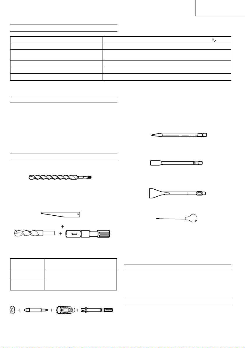
SPECIFICATIONS
Voltage (by areas)* (110V, 115V, 120V, 127V, 220V, 230V, 240V)
Power input 950 W*
Capacity Drill bit: 40 mm
No load speed 360/min.
Full-load blow 2800/min.
Weight (without cord, side handle) 6.7 kg
*Be sure to check the nameplate on product as it is subject to change by areas.
Core bit: 105 mm
English
STANDARD ACCESSORIES
(1) Case (Molded plastic) ............................................... 1
(2) Side Handle ................................................................ 1
(3) Stopper ........................................................................1
(4) Hexagon Bar Wrench (for 6 mm screw) ............. 1
(5) Hexagon Bar Wrench (for 5 mm screw) ............. 1
(6) Hammer Grease A .................................................... 1
(7) Dust Cover ..................................................................1
Standard accessories are subject to change without
notice.
OPTIONAL ACCESSORIES (sold separately)
1. Through-hole drilling (Rotation + Hammering)
(1) Drill bit (spline shank)
Overall length: 400 mm
External dia.: 12.7, 25.4, 38.1 mm
2. Anchor hole drilling (Rotation + Hammering)
(3) Cotter
(1) Drill bit (taper shank)
Taper shank
adapter
A-taper
B-taper
3. Large dia. hole boring (Rotation + Hammering)
(1) Center
(Guide
plate)
Application drill bit
Taper shank adapter formed Ataper or B-taper is provided as
optional accessory, but drill bit
for it is not provided.
pin
(2) Taper shank
(2) Core
bit
adapter
(Spline shank)
(3) Core bit
shank
(Spline shank)
(1) Center pin
䢇 Applied to core bits from 38 mm to 105 mm
(2) Core bit
䢇 External dia. 50, 105 mm (with guide plate)
(3) Core bit shank
䢇 Applied to core bits above 38 mm
4. Crushing (Hammering)
(1) Bull point
Overall length: 300 mm
5. Groove digging and edging (Hammering)
(1) Cold chisel
Overall length: 300, 460 mm
6. Asphalt cutting (Hammering)
(1) Cutter
7. Syringe (for chip removal)
8. Hammer grease A
500 g (in a can)
70 g (in a green tube)
30 g (in a green tube)
Optional accessories are subject to change without
notice.
APPLICATIONS
䡬 Drilling holes in concrete
䡬 Drilling anchor holes
䡬 Crushing concrete, chipping, digging, and squaring
(by applying optional accessories)
PRIOR TO OPERATION
1. Power source
Ensure that the power source to be utilized conforms
to the power requirements specified on the product
nameplate.
6
Page 8

English
2. Power switch
Ensure that the power switch is in the OFF position.
If the plug is connected to a receptacle while the
power switch is in the ON position, the power tool
will start operating immediately, which could cause
a serious accident.
3. Extension cord
When the work area is removed from the power
source, use an extension cord of sufficient thickness
and rated capacity. The extension cord should be
kept as short as practicable.
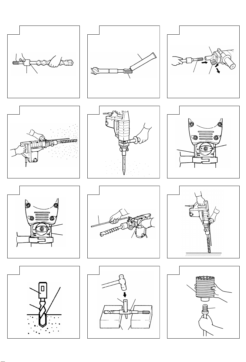
4. How to install dust cover (Fig. 1)
Always install the dust cover on the drill bit or the
taper shank adapter.
Insert the dust cover until it lies flush in the groove.
NOTE
For a thick drill bit, insert the dust cover from drill
rear.
5. How to install tool
NOTE
For tools such as a bull point and a cold chisel,
use only Hitachi genuine parts.
(1) Clean, then smear the tool shank with the grease
provided in the green tube (Fig. 2).
(2) Pull the tool holder in the direction of arrow A and
rotate it in the direction of arrow B
(counterclockwise). Fully insert the tool shank into
the hexagonal hole of the front cover. (Fig. 3)
(3) Return the tool holder to fix the tool.
NOTE
Remove in the reverse order to installation.
HOW TO USE THE ROTARY HAMMER
1. How to drill holes (Fig. 4)
(1) Pull the switch trigger after applying the drill bit
tip to the drilling position.
(2) It is unnecessary to forcibly press the rotary hammer
main body. It is sufficient to slightly press the rotary
hammer to an extent that shavings are freely
discharged.
CAUTION
Although this machine is equipped with a safety
clutch, if the drill bit becomes bound in concrete
or other material, the resultant stoppage of the drill
bit could cause the machine body to turn in reaction.
Ensure that the main handle and side handle are
gripped firmly during operation.
2. How to chip or crush (Fig. 5)
By applying the tool tip to the chipping or crushing
position, operate the rotary hammer by utilizing its
empty weight.
Forcible pressing or thrusting is unnecessary.
3. How to select rotation-hammering and hammering.
(1) Rotation-hammering (Fig. 6)
Rotate the selector lever clockwise so that the ▲
mark on the selector lever is aligned with the ▲
mark on the side of the
cover.
(2) Hammering (Fig. 7)
Rotate the selector lever counterclockwise so that
the ▲ mark on the selector lever is aligned with
the ▲ mark on the side of the
under cover.
mark on the under
mark on the
CAUTION
Turning the selector lever during motor rotation will
rotate the tool accidentally. The selector lever should
only be turned when the motor is stopped.
4. Install the stopper (Fig. 8)
(1) Loosen the side handle and insert the straight portion
of the stopper into the handle bolt hole.
(2) Move the stopper to the specified position and
rotate the grip of the side handle clockwise to fix
the stopper.
5. Warming up (Fig. 9)
The grease lubrication system in this unit may
require warming up in cold regions.
Position the end of the bit so makes contact with
the concrete, turn on the switch and perform the
warming up operation. Make sure that a hitting
sound is produced and then use the unit.
CAUTION
When the warming up operation is performed, hold
the side handle and the main unit securely with
both hands to maintain a secure grip and be careful
not to twist your body by the jammed drill bit.
6. When a taper shank adapter is used. (Fig. 10)
(1) Install drill bit with taper shank in the taper shank
adapter.
(2) Turn the power on and drill a base hole to the depth
sounded by indicating groove on the drill bit.
(3) After cleaning out dust with a syringe, attach the
plug to the anchor tip and drive in the anchor with
a manual hammer.
(4) To remove the drill bit (taper shank), insert the
cotter into the slot of the taper shank adapter and
strike the head of the cotter with a manual hammer
supporting on a rest. (Fig. 11)
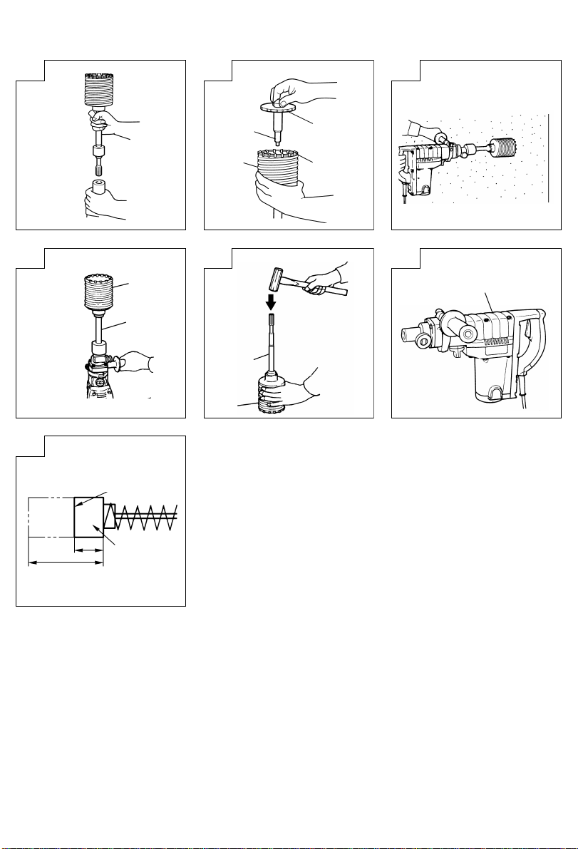
HOW TO HANDLE A CORE BIT
When a core bit is used, large diameter holes and
blind holes can be drilled. In this case, use optional
accessories for core bits (such as a center pin and
core bit shank) for more efficient operation.
1. Mounting
CAUTION
Prior to mounting a core bit, always disconnect the
plug from the receptacle.
(1) Mount the core bit on the core bit shank. (Fig. 12)
Before that, feed oil to the screw portion of core
bit shank for easy dismounting.
(2) Mount the core bit shank on the main body in the
same manner as in mounting the drill bit and the
bull point. (Fig. 13)
(3) Insert the center pin into the guide plate until it
reaches the extremity.
(4) Fit in the guide plate by aligning its concaved portion
with the core bit tip. When the position of the
concave is shifted by turning the guide plate right
or left, the guide plate never slips off even when
the drill is used in a downward direction.
(Fig. 14)
2. Drilling holes
(1) Insert the plug into a receptacle.
(2) A spring is built in the center pin. By straightly and
gently pressing it to the wall or floor surface, the
entire surface of the core bit tip attains contact to
start the hole drilling job. (Fig. 15)
7
Page 9

English
(3) When the hole depth reaches approximately 5 mm,
the hole position can be determined. Then remove
the center pin and guide plate from the core bit
and continue the hole drilling job.
CAUTION
When removing the center pin and guide plate,
always disconnect the plug from the receptacle.
3. How to dismount the core bit
䡬 By holding the drill (with the core bit inserted) in
an upward position, drive the drill to repeat
hammering operation two or three times, whereby
the screw is loosened and the drill becomes ready
for disassembly. (Fig. 16)
䡬 Remove the core bit shank from the drill, hold the
core bit with one hand, and strongly strike the head
of the spline portion of the core bit shank with a
manual hammer two or three times, whereby the
round head screw is loosened and the drill is ready
for disassembly. (Fig. 17)
HOW TO REPLACE GREASE
This machine is of full air-tight construction to protect
against dust and to prevent lubricant leakage.
Therefore, the machine can be used without lubrication
for long periods. Replace the grease as described
below.
1. Grease replacement period
After purchase, replace grease after every 6 months
of usage. Ask for grease replacement at the nearest
Hitachi Authorized Service Center. Proceed for
replacement of grease.
2. Grease replenishment
CAUTION
Before replenishing the grease, turn the power off
and pull out the power plug.
(1) Remove the crank case cover and wipe off the
grease inside. (Fig. 18)
(2) Supply 20g of Hitachi Electric Hammer Grease A
(Standard accessory, contained in tube) to the crank
case.
As the tube contain 30g of grease, supply 2/3 of
the contained grease.
(3) After replenishing the grease, install the crank case
cover securely.
NOTE
The Hitachi Electric Hammer Grease A is of the low
viscosity type. If necessary purchase from a Hitachi
Authorized Service Center.
MAINTENANCE AND INSPECTION
1. Inspecting the tool
Since use of a dull tool will degrade efficiency and
cause possible motor malfunction, sharpen or
replace the tool as soon as abrasion is noted.
2. Inspecting the mounting screws:
Regularly inspect all mounting screws and ensure
that they are properly tightened. Should any of the
screws be loose, retighten them immediately. Failure
to do so could result in serious hazard.
3. Maintenance of the motor
The motor unit winding is the very “heart” of the
power tool. Exercise due care to ensure the winding
does not become damaged and/or wet with oil or
water.
4. Inspecting the carbon brushes (Fig. 19)
The Motor employs carbon brushes which are
consumable parts. When they become worn to or
near the “wear limit”, it could result in motor trouble.
When an auto-stop carbon brush is equipped, the
motor will stop automatically. At that time, replace
both carbon brushes with new ones which have the
same carbon brush Numbers shown in the figure.
In addition, always keep carbon brushes clean and
ensure that they slide freely within the brush holders.
5. Replacing carbon brushes
Loosen the two set screws and remove the tail
cover. Remove the brush caps and carbon brushes.
After replacing the carbon brushes, tighten the brush
caps securely and install the tail cover with securely
tightening two set screws.
NOTE
Due HITACHI’s continuing program of research and
development, the specifications herein are subject to
change without prior notice.
IMPORTANT
Correct connection of the plug
The wires of the main lead are coloured in accordance
with the following code:
Blue: — Neutral
Brown: — Live
As the colours of the wires in the main lead of this
tool may not correspond with the coloured markings
identifying the terminals in your plug proceed as
follows:
The wire coloured blue must be connected to the
terminal marked with the letter N or coloured black.
The wire coloured brown must be connected to the
terminal marked with the letter L or coloured red.
Neither core must be connected to the each terminal.
NOTE
This requirement is provided according to BRITISH
STANDARD 2769: 1984.
Therefore, the letter code and colour code may not be
applicable to other markets except The United Kingdom.
Information concerning airborne noise and vibration
The measured values were determined according to
EN50144.
The typical A-weighted sound pressure level: 89 dB (A)
The typical A-weighted sound power level: 102 dB (A)
Wear ear protection.
The typical weighted root mean square acceleration
value: 10 m/s
2
8
Page 10

Deutsch
ALLGEMEINE VORSICHTSMASSNAHMEN
WARNUNG! Bei der Verwendung von Elektrowerkzeugen
müssen immer die grundlegenden Vorsichtsmaßnahmen
befolgt werden, um das Risiko von Feuer, elektrischem
Schlag und persönlicher Verletzung und den
nachfolgenden Punkten zu vermeiden.
Lesen Sie diese Anweisungen völlig, bevor Sie dieses
Erzeugnis verwenden, und bewahren Sie diese
Anweisungen auf.
Für sicheren Betrieb:
1. Der Arbeitsplatz sollte sauber gehalten werden.
Unaufgeräumte Arbeitsplätze und Werkbänke
erhöhen die Unfallgefahr.
2. Die Betriebsbedingungen beachten.
Elektrowerkzeuge sollten nicht dem Regen
ausgesetzt werden.
Ebenfalls sollten Sie nicht an feuchten oder nassen
Plätzen gebraucht werden.
Der Arbeitsplatz sollte gut beleuchtet sein.
Verwenden Sie Elektrowerkzeuge nicht an Orten,
an denen die Gefahr von Feuer oder Explosion
besteht.
3. Schutzmaßnahmen gegen elektrische Schläge
treffen. Darauf achten, daß das Gehäuse nicht in
Kontakt mit geerdeten Flächen kommt, z. (z.B.
Rohre, Radiatoren, Elektroherde, Kühlschränke).
4. Kinder sollten vom Gerät ferngehalten werden.
Vermeiden, daß andere Personen mit dem
Werkzeung oder Verlängerungskabel in Kontakt
kommen.
5. Nicht benutzte Werkzeuge sollten sicher aufbewahrt
werden. Sie sollten an einem trockenen und
verschließbaren Ort aufbewahrt werden, damit
Kinder sie nicht in die Hände bekommen.
6. Werkzeuge sollten nicht mit übermäßiger Gewalt
verwendet werden. Ihre Leistung ist besser und
sicherer, wenn sie mit der vorgeschriebenen
Geschwindigkeit verwendet werden.
7. Nur die korrekten Werkzeuge verwenden. Niemals
ein kleineres Werkzeug oder Zusatzgerät für
Arbeiten verwenden, die Hochleistungsgeräte
erfordern. Nur Werkzeuge verwenden, die dem
Verwendungszweck entsprechen, d.h. niemals eine
Kreissäge zum Sägen von Ästen oder
Baumstämmen verwenden.
8. Die richtige Kleidung tragen. Keine lose Kleidung
oder Schmuck tragen, da sich lose Kleidungsstücke
in den bewegenden Teilen verfangen kònnen. Bei
Arbeiten im Freien sollten Gummihandschuhe und
rutschfeste Schuhe getragen werden.
9. Es sollte eine Sicherheitsbrille getragen werden.
Bei Arbeiten mit Staubentwicklung sollte eine
Gesichts- oder Staubmaske getragen werden.
10. Schließen Sie eine Staubabsaugvorrichtung an.
Wenn Vorrichtungen für den Anschluß von
Staubabsaug- und -sammelvorrichtungen
vorhanden sind, so stellen Sie sicher, daß diese
angeschlossen sind und richtig verwendet werden.
11. Niemals das Kabel mißbrauchen. Ein Werkzeug
niemals am Kabel tragen oder bei Abtrennung
von der Steckdose das Kabel harausreißen. Das
Kabel sollte gegen Hitze, Öl und scharfe Kanten
geschützt werden.
9
12. Den Arbeitsplatz gut absichern. Zwingen oder einen
Schraubstock zur Befestigung des Werkstücks
verwenden. Das ist sicherer als die Benutzung der
Hände und macht beide Hände zur Bedienung des
Werkzeugs frei.
13. Sich niemals weit überbeugen. Immer einen festen
Stand und ein sicheres Gleichgewicht bewahren.
14. Die Werkzeuge sollten sorgfältig behandelt werden.
Für einen einwandfreien und sicheren Betrieb
sollten sie stets scharf sein und saubergehalten
werden. Die Anleitungen für Schmierung und
Austausch des Zuehörs unbedingt einhalten. Die
Kabel der Geräte regelmäßig überprüfen und bei
Beschädigung durch eine autorisierte
Kundendienststelle reparieren lassen.
Ebenfalls die Verlägerungskabel regelmäßig
überprüfen und bei Beschädigung auswechseln.
Die Handgriffe sollten stets trocken und sauber
sein, sowie keine Öl- oder Schmierfett stellen
aufweisen.
15. Werkzeuge vom Netz trennen, wenn sie nicht
benutzt werden, vor Wartungsarbeiten und beim
Austausch von Zubehörteilen wie z.B. Blätter,
Bohrer und Messer.
16. Alle Stellkeile und Schraubenschlüssel entfernen.
Vor Einschaltung des Gerätes darauf achten, daß
alle Stellkeile und Schraubenschlüssel entfernt
worden sind.
17. Ein unbeabsichtigtes Einschalten sollte vermieden
werden. Niemals ein angeschlossenes Werkzeug
mit dem Finger am Schalter tragen. Vor Anschluß
überprüfen, ob das Gerät ausgeschaltet ist.
18. Im Freien ein Verlängerungskabel verwenden. Nur
ein Verlängerungskabel verwenden, das für die
Verwendung im Freien markiert ist.
19. Den Arbeitsvorgang immer unter Kontrolle haben.
Das Gerät niemals in einem abgespannten Zustand
verwenden.
20. Beschädigte Teile überprüfen. Vor Benutzung des
Werkzeugs sollten beschädigte Teile oder
Schutzvorrichtungen sorgfältig überprüft werden,
um festzustellen, ob sie einwandfrei funktionieren
und die vorgesehene Funktion erfüllen,
Ausrichtung, Verbindungen sowie Anbringung sich
bewegender Teile überprüfen. Ebenfalls
überprufen, ob Teile gebrochen sind. Teile oder
Schutzvorrichtungen, die beschädigt sind, sollten,
wenn in dieser Bedienungsanleitung nichts anderes
erwähnt ist, durch eine autorisierte
Kundendienststelle ausge wechselt oder repariert
werden. Dasselbe gilt für defekte Schalter.
Wenn sich das Werkzeug nicht mit dem Schalter
ein- oder ausschalten läßt, sollte das Werkzeug
nicht verwendet werden.
21. Warnung
Die Verwendung von anderem Zubehör oder
anderen Zusätzen als in dieser Bedienungsanleitung empfohlen kann das Risiko einer
Körperverletzung einschließen.
22. Lassen Sie Ihr Werkzeug durch qualifiziertes
Personal reparieren. Dieses Elektrowerkzeug
entspricht den zutreffenden Sicherheitsanforderungen. Reparaturen sollten nur von
qualifiziertem Personal unter Verwendung von
Originalersatzteilen durchgeführt werden, da sonst
beträchtliche Gefahr für den Benutzer auftreten
kann.
Page 11
Deutsch
VORSICHTSMASSNAHMEN BEI DER
BENUTZUNG DES BOHRHAMMERS
䡬 Ohrenstöpsel zum Schutz der Ohren während des
Betriebs tragen.
䡬 Die Bohrerspitze nicht während oder unmittelbar
nach dem Betrieb berühren. Die Bohrerspitze wird
während des Betriebs sehr heiß, und es könnte zu
ernsthaften Verbrennungen kommen.
䡬 Bevor man in einer Wand, dem Boden oder der
Decke etwas ausbricht, meißelt oder bohrt, muß
man sich sorgfältig davon überzeugen, daß keine
elektrischen Kabel oder Kabelrohre darunter liegen.
䡬 Immer den Körper-Handgriff und Seiten-Handgriff
des Elektrowerkzeugs festhalten, weil sonst die
entstehende Gegenkraft zu ungenauem und sogar
gefährlichem Arbeiten führen kann.
TECHNISCHE DATEN
Spannung (je nach Gebiet)* (110V, 115V, 120V, 127V, 220V, 230V, 240V)
Leistungsaufnahme 950 W*
Kapazität Bohrer: 40 mm
Leerlaufdrehzahl 360/min.
Vollastschlagzahl 2800/min.
Gewicht (ohne Kabel und Seitengriff) 6,7 kg
* Vergessen Sie nicht, die Produktangaben auf den Typenschild zu überprüfen, da sich diese ja nach Verkaufsgebiet
ändern.
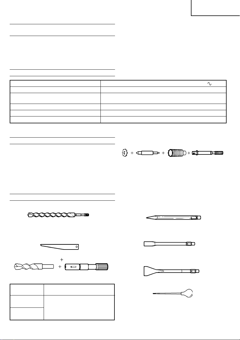
STANDARDZUBEHÖR
(1) Gehäuse (Plastik) .......................................................1
(2) Seitengriff ...................................................................1
(3) Anschlagstange ..........................................................1
(4) Sechskantschlüssel (für 6 mm Schraube) ............ 1
(5) Sechskantschlüssel (für 5 mm Schraube) ............ 1
(6) Hammer Schmierfett A ............................................ 1
(7) Staubdeckel ................................................................1
Das Standardzubehör kann ohne vorherige Bekanntmachung jederzeit geändert werden
SONDERZUBEHÖR (separat zu beziehen)
1. Durchgangsbohrung (Drehung + Schlag)
3. Lochbohren mit weitem Durchschnitt
(Führungsplatte)
(1) Mittelstift
䢇 Anwendbar mit Bohrkronen 38 mm ~ 105 mm
(2) Bohrkrone
䢇 Außendurchschnitt
(3) Bohrkronenschenkel
䢇 Anwendbar mit Bohrkronen über 38 mm
4. Brechen (Schlagen)
Bohrkrone: 105 mm
(Drehung + Schlag)
(1) Mittelstift
50 105 mm (mit Führungsplatte)
(2) Bohrkrone
(3) Bohrkronen-
schenkel
(Keilrutzapfen)
(1) Bohrer (Keilrutzapfen)
Gesamtlänge: 400 mm
Außendurchschnitt: 12,7 25,4 38,1 mm
2. Ankerlochbohren (Drehung + Schlag)
(3) Keil
(1) Bohrer (mit
konischem Schaft)
Konusschaftadapter
A-Konus
B-Konus
Anwendbare Bohrerpitze
Der Konusschaftadapter in Form
von A-Konus oder B-Konus
wird wahlweise geliefert, aber
die passende Bohrerspitze wird
nicht mitgeliefert.
(2) Konusschaftadapter
(Keilrutzapfen)
(1) Spitzmeißel
Gesamtlänge: 300 mm
5. Nuten und Kanten (Schlagen)
(1) Kaltmeißel
Gesamtlänge: 300 460 mm
6. Asphaltschneiden (Schlagen)
(1) Spatmeißel
7. Spritze (für Schnipselentfernung)
8. Hammer Schmierfett A
500 g (Dose)
70 g (in grüner Tube)
30 g (in grüner Tube)
Das Sonderzubehör kann ohne vorherige
Bekanntmachung jederzeit geändert werden.
10
Page 12

Deutsch
ANWENDUNGSGEBIETE
䡬 Bohren von Löchern in Beton
䡬 Bohren von Ankerlöchern
䡬 Brechen von Beton, Abmeißeln, Graben und Kanten
(durch Verwendung von wahlweisem Zuberhör)
VOR INBETRIEBNAHME
1. Netzspannung
Prüfen, daß die zu verwendende Netzspannung der
Angabe auf dem Typenschild entspricht.
2. Netzschalter
Prüfen, daß der Netzschalter auf „AUS” steht. Wenn
der Stecker an das Netz angeschlossen wird,
während der Schalter auf „EIN” steht, beginnt das
Werkzeug sofort zu laufen, was gefährlicht ist.
3. Verlängerungskabel
Wenn der Arbeitsbereich nicht in der Nähe des
Netzanschlusses liegt, ist ein Verlängerungskabel
ausreichenden Querschnitts und ausreichender
Nennleistung zu verwenden. Das Verlängerungskabel
sollte so kurz wie möglich gehalten werden.
4. Anbringen des Staubdeckels (Abb. 1)
Immer den Staubdeckel am Konus-Werkzeughalter
des Bohrers anbringen.
Den Staubdeckel einsetzen, bis er genau in der Rille
liegt.
ANMERKUNG
Bei einem dicken Bohrer den Staubdeckel vom
Hinterteil des Bohrers aus anbringen.
5. Anbringen des Werkzeugs
ANMERKUNG
Immer Original-HITACHI Bohrer und Spitzmeißel
sowie Werkzeug verwenden.
(1) Den Werkzeugschaft reinigen und dann mit Hilfe
des mitgelieferten Fettes schmieren (in grüner Tube).
(Abb. 2)
(2) Den Werkzeughalter in Richtung Pfeil A ziehen und
in Richtung Pfeil B drehen (nach links).
Den Werkzeugschaft vollkommen in das sechskantige
Loch der Vorderabdeckung einsetzen. (Abb. 3)
(3) Den Werkzeughalter zurückstellen, um das Werkzeug
zu befestigen.
ANMERKUNG
Zum Abnehmen das obige Verfahren umgekehrt
ausführen.
EINSATZ DES BOHRHAMMERS
1. Löcherbohren: (Abb. 4)
(1) Der Schalter wird durchgezogen, nachdem die
Bohrspitze an der gewünschten Bohrstelle aufgesetzt
ist.
(2) Es ist nicht erforderlich, großen Druck auf die
Bohrmaschine auszuüben. Es reicht ein geringer
Druck, und zwar so stark, daß die Bohrspäne
abgeführt werden.
ACHTUNG
Obwohl die Maschine mit einer Sicherheitskupplung
ausgestattet ist, wenn sich der Bohrer in Beton oder
sonstigem Material verklemmt, kann der Stillstand
des Bohrers dazu führen, daß sich die Maschine zu
drehen beginnt. Es ist darauf zu achten, daß der
Hauptgriff und der seitliche Handgriff während des
Betriebs gut festgehalten werden.
11
2. Anweisung für Abmeißeln oder Brechen (Abb. 5)
Das Werkzeug an die abzumeißelnde oder brechende
Stelle ansetzen und den Schlagbohrer durch
Anwendung seines Eigengewichtes in Betrieb setzen,
Kraftanwendung beim Drücken oder beim Einsatz
ist nicht erforderlich.
3. Wählen des Drehschlagbohrens und des Schlag-
bohrens
(1) Drehschlagbohren (Abb. 6)
Den Wahlhebel im Uhrzeigersinn drehen, bis die
Markierung ▲ am Wahlhebel auf die Markierung ▲
an der Seite der Markierung
Abdeckung ausgerichtet ist.
(2) Schlagbohren (Abb. 7)
Den Wahlhebel gegen den Uhrzeigersinn drehen,
bis die Markierung ▲ am Wahlhebel auf die
Markierung ▲ an der Seite der Markierung
der unteren Abdeckung ausgerichtet ist.
VORSICHT
Wenn der Wahlhebel bei Motordrehung gedreht
wird, wird sich das Werkzeug zufällig drehen. Den
Wahlhebel nur dann drehen, wenn der Motor nicht
läuft.
4. Anbringen der Anschlagstange (Abb. 8)
(1) Den Seitengriff lösen und den geraden Teil der
Anschlagstange in das Bolzenloch des Seitengriffs
einschieben.
(2) Die Anschlagstange in die angegebene Stellung
bringen und den Seitengriff nach rechts drehen, um
die Anschlagstange zu befestigen.
5. Warmlaufbetrieb (Abb. 9)
Da dieses Gerät Fettschmierung verwendet, kann in
kalten Bereichen Warmlaufen erforderlich sein.
Die Bohrerspitze gegen Beton drücken, den Schalter
des Gerätes einschalten und das Gerät verwenden,
nachdem Schlaggeräusch zu hören ist.
ACHTUNG:
Beim Warmlaufen den Seitengriff und den
Gerätkörper mit beiden Händen gut festhalten, damit
Sie sich durch einen verklemmten Bohrer nicht
verrenken.
6. Verwendung eines Konus-Werkzeughalters (Abb. 10)
(1) Einen Bohrer mit konischem Schaft am Konus-
Werkzeughalter anbringen.
(2) Die Maschine einschalten und ein Loch bohren, bis
die Anzeigerille am Bohrer die Bohrlochtiefe anzeigt.
(3) Nach Ausblasen des Bohrstaubs mit einem Blasebalg
den Expansionskonus an der Ankerspitze anbringen
und den Anker mit einem Hammer einführen.
(4) Zur Entferung des Bohrers (Kegelschafts) einen Dorn
in den Schlitz des Kegelschaftadapters einführen
und mit einem Hammer gestützt durch eine Auflage
auf den Kopf des Dorns schlagen (Abb. 11)
an der unteren
an
VERWENDUNG EINER BOHRKRONE
Bei Verwendung einer Bohrkrone können Löcher mit
großem Durchmesser sowie Sacklöcher gebohrt werden.
Benutzen Sie in diesem Fall das wahlweise Zubehör für
Bohrkronen (wie Zentrierstift und Bohrkronenschaft),
um bessere Bohrleistungen zu erzielen.
1. Anbringen
ACHTUNG
Nehmen Sie vor dem Aufsetzen der Bohrkrone den
Stecker aus der Steckdose.
Page 13

Deutsch
(1) Bringen Sie die Bohrkrone auf dem Bohrerschaft an.
(Abb. 12)
(2) Bringen Sie den Bohrset-Bohrhalter mit Gewinde-
aufnahme am Bohrhammergehäuse auf die gleiche
Weise wie den Bohrer oder Spitzmeißel an.
(Abb. 13)
(3) Führen Sie den Zentrierstift in die Führungsplatte
bis zum Ende ein.
(4) Bringen Sie die Führungsplatte durch Ausrichten
des konkaven Teils auf die Bohrkronenspitze an.
Wenn die Stellung des konkaven Teils durch Drehen
der Führungsplatte nach links oder rechts verschoben
wird, rutscht die Führungsplatte auch bei nach unten
gerichtetem Bohrer nie ab. (Abb. 14)
2. Bohren von Löchern
(1) Stecken Sie den Stecker in die Steckdose.
(2) Der Zentrierstift ist mit einer Feder ausgerüstet.
Durch geradlinig leicht ausgeübten Druck an die
Wand oder Bodenfläcke kommt die gesamte Spitze
der Bohrkrone in Kontakt mit dem zu bohrenden
Material. (Abb. 15)
(3) Wenn die Bohrlochtiefe ungefähr 5 mm ereicht, kann
die Bohrlochposition bestimmt werden. Nehmen Sie
den Zentrierstift und die Führungsplatte von der
Bohrkrone ab und setzen Sie die Bohrarbeit fort.
VORSICHT
Nehmen Sie beim Abnehmen dez Zentrierstiftes
und der Führungsplatte den Stecker aus der
Steckdose.
3. Abnehmen der Bohrkrone
嘷 Halten Sie den Bohrhammer (mit eingesetzter
Bohrkrone) nach oben zeigend fest und drehen Sie
den Schlagbohrer, bis etwa zwei oder drei
Schlagtakte wiederholt sind, wodurch sich die
Schraube löst und der Bohrer abgenommen werden
kann. (Abb. 16)
嘷 Entfernen Sie den Bohrkronenschaft vor der
Maschine und halten Sie dabei die Bohrkrone mit
einer Hand, während Sie den Kopf des Keilrotzapfers
des Bohrkronenschaftes mit einem Hammer zwei
oder drei Mal kräftig beklopfen, wodurch sich die
Rundkopfschraube löst und der Bohrer abgenommen
werden kann. (Abb. 17)
SCHMIERFETTWECHSEL
Diese Maschine ist volkommen luftdicht, um Eintritt von
Staub und Fettlecken zu vermeiden. Deshalb kann sie
auf lange Zeit ohne Schmieren gebraucht werden. Zum
Schmierfettwechsel wie unten angegeben vorgehen.
1. Wechselzeit
Nach dem Einkauf das Schmierfett alle 6
Gebrauchsmonate wechseln. Wenden Sie sich an
Ihr autorisiertes Hitachi Service Center, um den
Fettwechsel auszuführen.
2. Schmierfett auffüllung
VORSICHT
Vor dem Schmierfett auffüllung die Maschine
abschalten und den Netzstecker herausnehmen.
(1) Die Kurbelgehäuseabdeckung abnehmen und das
Fett von der Innenseite abwischen. (Abb. 18)
(2) Mit 20 Gramm Hitachi Hammer Schmierfett A
(Normal-Zubehör in der Tube) das Kurbelgehäuse
versorgen.
Da die Tube 30 Gramm Schmierfett enthält, 2/3 des
Inhalts verwenden.
(3) Nach dem auffüllung die Kurbelgehäuseabdeckung
wieder sicher anbringen.
ANMERKUNG
Das Hitachi Elektro Hammer Schmierfett A ist von
niedrigem Flüssigkeitsgrad. Falls notwendig, kaufen
Sie eine neue Tube bei Ihrer Hitachi Service Center.
WARTUNG UND INSPEKTION
1. Inspektion des Werkzeugs
Da Gebrauch eines stumpfen Werkzeugs die Leistung
vermindert und ein mögliches Versagen des Motors
verursacht, ist das Werkzeug zu schleifen oder zu
ersetzen, wenn Verschleiß festgestellt wird.
2. Inspektion der Befestigungsschrauben:
Alle Befestigungsschrauben werden regelmäßig
inspiziert und geprüft, ob sie gut angezogen sind.
Wenn sich eine der Schrauben lockert, muß sie
sofort wieder angezogen werden. Geschieht das
nicht, kann das zu erheblichen Gefahren führen.
3. Wartung des Motors:
Die Motorwicklung ist das „HERZ” des
Elektrowerkzeugs. Daher ist besonders sorgfältig darauf
zu achten, daß die Wicklung nicht beschädigt wird
und/oder mit Öl oder Wasser in Berührung kommt.
4. Inspektion der Kohlebürsten (Abb. 19)
Im Motor sind Kohlebürsten verwendet, die
Verbauchsteile sind. Wenn sie abgenützt sind, kann
es zu Motorschäden führen. Wenn der Motor mit
einer Auto-Stop Kohlebürste ausgestattet ist, wird
er automatisch anhalten. Beide Kohlebürsten sollen
dann durch neue ersetzt werden, die dieselbe
Bürstennummer tragen, wie auf der Abbildung.
Darüber hinaus müssen die Kohlebürsten immer
sauber gehalten werden und müssen sich in der
Bürstenhalterung frei bewegen können.
5. Wiedereinsetzen der Kohlebürsten
Die Stellschraube lösen und die hintere Abdeckung
entfernen. Die Bürstenkappe und die Kohlebürste
entfernen. Nach dem Auswechseln der Kohlebürste
die Bürstenkappe sicher anziehen und die hintere
Abdeckung installieren.
ANMERKUNG
Aufgrund des ständigen Forschungs-und Entwicklungsprogramms von HITACHI sind Änderungen der hierin
gemachten technischen Angaben nicht ausgeschlossen.
Information über Betriebslärm und Vibration
Die Meßwerte wurden entsprechend EN50144 bestimmt.
Der typische A-gewichtete Schalldruckt ist 89 dB (A).
Der typische A-gewichtete Schalleistungspegel ist 102
dB (A).
Bei der Arbeit immer einen Ohrenschutz tragen.
Der typische gewogene quadratische Mittelwert für die
Beschleunigung ist 10 m/s2.
12
Page 14

Français
PRECAUTIONS GENERALES DE TRAVAIL
ATTENTION! Lors de l’utilisation d’un outillage électrique,
les précautions de base doivent être respectées de
manière à réduire les risques d’incendie, de secousse
électrique et de blessure corporelle, y compris les
précautions suivantes.
Lire ces instructions avant d’utiliser le produit et conserver
ces instructions pour référence.
Pour assurer un fonctionnement sûr:
1. Maintenir l’aire de travail propre. Des ateliers ou
des établis en désordre risquent de provoquer des
accidents.
2. Tenir compte de l’environnement de l’aire de
travail. Ne pas exposer les outils électriques à la
pluie.
Ne pas les utiliser dans des endroits humides.
Travailler dans un endroit bien éclairé.
Ne pas utiliser d’outillage électrique s’il existe un
risque d’incendie ou d’explosion.
3. Protection contre une décharge électrique. Eviter
tout contact corporel avec des surfaces de mise
à la terre telles que les tuyaux, radiateurs,
cuisinières et réfrigérateurs.
4. Tenir les enfants éloignés. Ne pas laisser les
visiteurs toucher l’outil ou son cordon
d’alimentation. Il est préférable de tenir les visiteurs
à l’écart de l’aire de travail.
5. Ranger les outils non utilisés. Quand on ne les
utilise pas, il est recommandé de ranger les outils
dans un endroit sec, verrouillé ou hors de portée
des enfants.
6. Ne pas forcer l’outil. Il fonctionnera mieux et plus
sûrement à la vitesse pour laquelle il a été concu.
7. Utiliser l’outil approprié. Ne pas essayer de faire
avec un petit outil le travail prévu pour un outil
plus important. Toujours utiliser l’outil adéquat;
par exemple, ne pas se servir d’une scie circulaire
pour couper des branches d’arbres ou des billots
de bois.
8. Porter des vêtements appropriés. Ne pas mettre
de vêtements flottants ou de bijoux qui risquent
d’être pris dans les pièces mobiles. Si l’on travaille
à l’extérieur, il est recommandé de porter des
gants de caoutchouc et des chaussures à semelles
antidérapantes. Veiller à s’attacher les cheveux ou
à mettre un bonnet si on a les cheveux longs.
9. Porter des lunettes protectrices. Mettre un masque
si l’opération de coupe crée de la poussière.
10. Relier l’équipement d’extraction de poussière.
Si des dispositifs sont prévus pour le raccordement
d’installations d’extraction et de collection de
poussière, s’assurer qu’ils sont correctement
raccordés et utilisés.
11. Prendre soin du fil. Ne jamais transporter l’outil
en le tenant par le fil et ne pas le débrancher en
tirant sur le fil d’un coup sec. Tenir le fil à l’abri
de la chaleur, l’éloigner de l’huile ou des bords
tranchants.
12. Fixer fermement la piêce à travailler. Utiliser des
agrafes ou un étau pour la maintenir. Ceci est plus
sûr que d’utiliser ses mains et cela les libêre pour
faire fonctionner l’outil.
13. Ne pas présumer de ses forces. Essayer de garder
son équilibre en toute circonstance.
14. Entretenir les outils avec soin. Les conserver bien
aiguisés et les nettoyer afin d’en obtenir les
meilleures performances et de pouvoir les utiliser
sans danger. Suivre les instructions pour le
graissage et le changement des accessoires.
Vérifier régulièrement les fils et cordons et s’ils
sont endommagés, les faire réparer par une
personne compétente. Vérifier régulièrement les
rallonges et les remplacer si elles sont
endommagées. Veiller à ce que les poignées soient
toujours sèches et propres, sans huile ni graisse.
15. Debrancher les outils lorsqu’on ne les utilise pas,
avant toute opération d’entretien et lors du
changement d’accessoire, comme par exemple
quand on change les lames, les forets, le fraises,
etc.
16. Retirer les clés de réglage. Prendre l’habitude de
toujours vérifier que les clés de réglage sont bien
retirées de l’appareil avant de le mettre en marche.
17. Eviter toute mise en marche accidentelle. Ne pas
transporter l’outil branché avec un doigt sur
l’interrupteur. S’assurer que l’interrupteur est sur
la position d’arrêt quand on branche l’outil.
18. Utilisation de rallonges à l’extérieur. Quand on
utilise l’outil à l’extérieur, ne se servir que des
rallonges prévues pour l’extérieur et portant une
marque distinctive.
19. Etre vigilant. Regardez bien ce que vous faites.
Faites appel à votre bon sens. N’utilisez pas l’outil
quand vous êtes fatigué.
20. Vérifier les pièces endommagées. Avant d’utiliser
davantage l’outil, vérifier attentivement toute pièce
endommagée afin de déterminer si l’outil peut
fonctionner correctement et effectuer le travail
pour lequel il est prévu. Vérifier l’alignement et
la flexion des pièces mobiles, la cassure des pièces,
le montage et toute autre condition risquant
d’affecter le bon fonctionnement de l’outil. Un
protecteur ou toute autre pièce endommagée devra
être correctement réparé ou remplacé par un
service d’entretien autorisé, sauf autre indication
dans ce mode d’emploi. Faire remplacer les
interrupteurs défectueux par un service d’entretien
autorisé. Ne pas utiliser l’outil si l’interrupteur ne
permet pas de le mettre en marche ou de l’arrêter.
21. Précaution
L’utilisation d’un accessoire ou dispositif annexe
autre que ceux conseillés dans ce mode d’emploi
peut entraîner un risque de blessure corporelle.
22. Confier la réparation de l'outil à un technicien
qualifié. Cet outil électrique a été conçu
conformément aux règles de sécurité en usage.
Les réparations doivent être effectuées par un
personnel qualifié utilisant des pièces d’origine.
Dans le cas contraire, l’utilisateur s’expose à des
risques graves.
13
Page 15

Français
PRECAUTIONS POUR L’UTILISATION DU
PERFORATEUR PERCUSSION
䡬 Utiliser des bouchons d’oreilles pour protéger vos
oreilles pendant le fonctionnement.
䡬 Ne pas toucher le foret pendant ou immédiatement
après le fonctionnement. Il devient très chaud et
peut causer des brûlures.
䡬 Avant de briser, découper ou percer un mur, le
plancher ou le plafond, s’assurer qu’aucun câble
électrique ou conduit n’y soit noyé.
䡬 Maintenir toujours fermenent la poignée principale
et la poignée latérale de la machine. Dans le cas
contraire, la force de recul peut amoindrir la précision
de travail et présenter aussi quelque danger.
CARACTERISTIQUES
Tension (par zone)* (110V, 115V, 120V, 127V, 220V, 230V, 240V)
Entrée 950 W*
Capacité Mèche: 40 mm
Vitesse sans charge 360/min.
Frappe pleine charge 2800/min.
Poids (sans cordon ni poignée latérale) 6,7 kg
*Assurez-vous de vérifier la plaque signalétique sur le produit, car elle peut changer suivant les zones.
ACCESSOIRES STANDARD
(1) Boîtier (Plastique) ...................................................... 1
(2) Poignée latérale ......................................................... 1
(3) Quenouille................................................................... 1
(4) Clef à barre hexagonale (pour vis de 6 mm).... 1
(5) Clef à barre hexagonale (pour vis de 5 mm).... 1
(6) Graisse A pour marteau.......................................... 1
(7) Cache-poussière .........................................................1
Les accessoires à option sont sujets à changement
sans préavis.
ACCESSOIRES EN OPTION (vendus séparément)
1. Perçage de trous de passage (rotation + percussion)
3. Perçage de trous à large diamètre (rotation +
(plaque
de
guidage)
(1) Goujon central
䢇 Appliqué à couronnes 38 mm ~ 105 mm
(2) Couronne
䢇 Dia. ext.
(3) Queue de couronne
䢇 Appliquè à couronnes de plus de 38 mm
4. Broyage (percussion)
Couronne: 105 mm
percussion)
(1) Goujon
central
50 105 mm (avec plaque de guidage)
(2) Couronne
(3) Queue de
cournne
(1) Mèche (queue cannelée)
Longueur totale: 400 mm
Dia. ext.: 12,7 25,4 38,1 mm
2. Perçage de trous d’ancrage (rotation + percussion)
(3) Clavette
(1) Mèche
(queue conique)
Raccord de
queue conique
Cône-A
Cône-B
Mèche applicable
La raccord de queue conique en
forme cône-A ou cône-B est
fourni en tant qu’accessoire sur
option, mais la mèche
correspondante n’est par fournie.
(2) Raccord de queue
conique
(queue cannelée)
(1) Point de broyage
Longueur totale: 300 mm
5. Creusage de rainures et cassure des angles
(percussion)
(1) Ciseau à froid
Longueur totale: 300 460 mm
6. Coupage d’asphalte (percussion)
(1) Fraise
7. Seringue (pour enlever déchets)
8. Graisse A pour marteau 500g (en boîte)
Les accessoires en option sont sujets à changement
sans préavis.
70g (en tube vert)
30g (en tube vert)
14
Page 16

Français
APPLICATIONS
䡬 Perçage de trous dans béton
䡬 Perçage de trous d’ancrage
䡬 Broyage du béton, burinage, creusage, et
équarrissage application des accessoires sur option)
AVANT LA MISE EN MARCHE
1. Source de puissance
S’assurer que la source de puissance à utiliser
correspond à la puissance indiquée sur la plaque
signalétique de produit.
2. Interrupteur de puissance
S’assurer que l’interrupteur de puissance est en
position ARRET. Si l'on branche la fiche alors que
l’interrupteur est sur MARCHE, l’outil démarre
immédiatement et peut provoquer un grave accident.
3. Fil de rallonge
Lorsque la zone de travail est éloignée de la source
de puissance, utiliser un fil de rallonge d’une
épaisseur suffisante et d’une capacité nominale
suffisante. Le fil de rallonge doit être aussi court
que possible.
4. Comment installer le cache-poussière (Fig. 1)
Toujours installer le cache-poussière sur le raccord
de la queue conique.
Insérer le cache-poussière bien à fleur de la rainure.
REMARQUE
Pour une mèche épaisse, insérer le cache-poussière
par l'arrière de la mèche.
5. Comment installer l’outil
REMARQUE
Pour les outils tels que pointe de broyage et ciseau
à froid n’utiliser que les pièces HITACHI authentiques.
(1) Nettoyer, puis graisser la queue de l’outil avec la
graisse fournie à cet effet en tube vert (Fig. 2)
(2) Tirer le porte-outil dans la direction de la flèche A
et le tourner dans la direction de la flèche B (sens
antihoraire). Insérer à fond la queue de l'outil dans
le trou hexagonal du couvercle frontal. (Fig. 3)
(3) Retourner le porte-outil pour fixer l'outil.
REMARQUE
Pour enlever l'outil procéder à l'inverse de son
installation.
UTILISATION
1. Comment percer des trous (Fig. 4)
(1) Tirer l’interrupteur après avoir appliqué la pointe
de la mèche à la position de forage.
(2) Il n’est pas nécessaire d’appuyer de force sur le
corps du perforateur percussion. Il sera suffisant
d’appuyer légèrement sur le perforateur percussion
jusqu’à ce que les éclats soient déchargés librement.
ATTENTION
Bien que cette machine soit équipée d’un cran de
sécurité, si la mèche est prise dans le béton ou
autre matériel l’arrêt de son fonctionnement pourrait
faire tourner le corps de la machine. Tenir fermement
la poignée principale et la poignée latérale pendant
le fonctionnement.
2. Comment buriner ou broyer (Fig. 5)
En appliquant la pointe de l'outil sur la position de
burinage ou de broyage, faire fonctionner le
15
perforateur percussion en utilisant son propre poids.
Il n’est pas nécessaire d’appuyer ou de pousser de
force.
3. Comment sélectionner rotation-percussion et
percussion
(1) Rotation-percussion (Fig. 6)
Faire tourner le sélecteur dans le sens des aiguilles
d’une montre, de façon que le repère ▲ du sélecteur
soit aligné sur le repère ▲ situé à côté du repère
du cache inférieur.
(2) Percussion (Fig. 7)
Faire tourner le sélecteur dans le sens inverse des
aiguilles d’une montre, de façon que le repère ▲
du sélecteur soit aligné sur le repère ▲ situé à côté
du repère
ATTENTION
Le fait de tourner le sélecteur pendant que le moteur
tourne entraînera la rotation accidentelle de l’outil.
Le sélecteur ne doit être tourné que lorsque le
moteur est à l’arrêt.
4. Installer la quenouille (Fig. 8)
(1) Desserrer la poignée latérale et insérer la partie
droite de la quenouille dans le trou du boulon de
la poignée.
(2) Déplacer la quenouille à la position spécifiée et faire
tourner l'attache coulissante de la poignée latérale
dans le sens des aiguilles d'une montre pour fixer
la quenouille.
5. Préchauffage (Fig. 9)
Le système de graissage de l’outil risque de devoir
être préchauffé dans les régions froides.
Placer l’extrémité de la mèche de façon qu’elle
entre en contact avec le béton, enclencher
l’interrupteur et effectuer une opération de
préchauffage. Bien s’assurer que l’outil fait entendre
un bruit de heurt, puis utiliser l’outil.
ATTENTION
Pendant l’opération de préchauffage, tenir
fermement la poignée latérale et le corps de l’outil
des deux mains de façon à garder une bonne prise
de l’outil et faire attention que le corps de l'opérateur
ne pivote pas sons l'effet d'une mèche coincée.
6. Lors de l’utilisation du raccord pour queue conique
(Fig. 10)
(1) Installer la mèche avec la queue conique dans le
raccord pour queue conique.
(2) Mettre l’outil en marche et percer un trou de base
jusqu’à la profondeur indiquée par la rainure
indicatrice de la mèche.
(3) Après avoir chassé les déchets avec une seringue,
fixer le bouchon à la pointe de l’ancre et enfoncer
l’ancre avec un marteau ordinaire.
(4) Pour retirer la mèche (queue conique), introduire
la clavette dans la fente du raccord de queue conique
et frapper la tête de la clavette avec un marteau
alors que le perceuse est placée sur le support.
(Fig. 11)
du cache inférieur.
UTILISATION DE LA COURONNE
Si la couronne est usée, il peut en résulter un perçage
de trous trop larges ou de trous borgnes. Dans ce
cas utiliser les accessoires sur option pour couronne
(tels que goujon central et queue de couronne) pour
pouvoir effectuer un travail rationnel.
Page 17

Français
1. Montage
ATTENTION
Avant de monter une couronne, débrancher toujours
l’outil de la prise de courant.
(1) Monter la couronne sur la queue de couronne.
(Fig. 12) Mais avant de la faire, graisser la vis de
la queue de couronne pour assurer un démontage
facile.
(2) Monter la queue de couronne sur le corps du
perforateur percussion de la même façon que pour
la mèche et la pointe de broyage. (Fig. 13)
(3) Insérer le goujon central dans la plaque de guidage
jusqu’à ce qu’il atteigne l’extrêmité.
(4) Installer la plaque de guidage en alignant sa partie
concave avec le bout de la couronne.
Quand la position de la partie concave est décalée
en tournant la plaque de guidage vers la droite ou
vers la gauche, la plaque de guidage ne glisse
jamais même quand l’outil est utilisé en le
maintenant vers le bas. (Fig. 14)
2. Perçage des trous
(1) Brancher l’outil à la prise de courant.
(2) Un ressort est incorporé dans le goujon central. En
l’appuyant doucement et tout droit au mur ou à la
surface du sol, la surface entière du bout de couronne
est en contact pour commencer le travail de perçage
de trous. (Fig. 15)
(3) Quand la profondeur du trou atteint environ 5 mm,
la position du trou peut être déterminée. Enlever
alors le goujon central et la plaque de guidage de
la couronne et continuer le travail de perçage de
trous.
ATTENTION
Quand vous enlevez le goujon central et la plaque
de guidage, débranchez toujours l’outil de la prise
de courant.
3. Comment démonter la couronne
䡬 En maintenant l’outil (avec la couronne insérée)
vers le haut, le faire marcher pour répéter le travail
de percussion deux ou trois fois; cette opération
desserrera la vis et l’outil sera prêt à être démonté.
(Fig. 16)
䡬 Enlever la queue de couronne de l’outil, maintenir
la couronne d’une main, et frapper fortement sur
la tête de la partie cannelée de la queue de couronne
avec un marteau ordinaire deux ou trois fois, ce
qui desserrera la vis à tête ronde et l’outil sera prêt
à être démonté. (Fig. 17)
COMMENT REMPLACER LA GRAISSE
Cette machine est de contruction entièrement
hermétique pour la protéger contre la poussière et
pour éviter les fuites de lubrifiant. Elle peut donc être
utilisée sans lubrification pendant longtemps.
Remplacer la graisse comme indiqué ci-dessous.
1. Période de remplacement
Remplacer la graisse après chaque période de 6
moins d’utilisation. Se procurer la graisse chez
l’Agence de service agréée Hitachi la plus proche.
Procéder au remplacement.
2. Plein de graisse
ATTENTION
Avant de faire le plein la graisse, fermer l’interrupteur
et débrancher l’outil de la prise de courant.
(1) Enlever le couvercle du carter et essuyer la graisse
à l’intérieur. (Fig. 18)
(2) Appliquer 20g de graisse pour marteau électrique
Hitachi A (en tube) au carter.
Etant donné que le tube contient 30g de graisse,
appliquer 2/3 du contenu.
(3) Après avoir fait le plein de graisse, installer
fermement le couvercle du carter.
REMARQUE
La graisse pour marteau électrique Hitachi A est du
type à viscosité faible. Si nécessaire, se procurer
la graisse chez un agent réparateur Hitachi agréé;
adressez-vous à votre Agent de service agréée
Hitachi pour vous en procurer de nouveau.
ENTRETIEN ET INSPECTION
1. Inspection de l’outil
Etant donné que l’utilisation d’un outil émoussé
réduira le rendement et provoquera éventuellement
un manuvais fonctionnement du moteur, aiguiser
ouremplacer l’outil dès qu’une abrasion apparaît.
2. Contrôle des vis de montage:
Vérifier régulièrement les vis de montage et s’assurer
qu’elles sont correctement serrées. Resserrer
immédiatement toute vis desserrée. Sinon, il y a
danger sérieux.
3. Entretien du moteur:
Le bobinage de l’ensemble moteur est le “coeur”
même de l’outil électro-portatif. Veiller soigneusement
à ce que ce bobinage ne soit pas endommagé et/
ou mouillé par de l’huile ou de l’eau.
4. Contrôle des balais en carbone (Fig. 19)
Le moteur utilise des balais en carbone qui sont
des pièces qui s’usent. Quand ils sont usés ou près
de la “limite d’usure”, il pourra en résulter un
mauvais fonctionnement du moteur.
Quand le moteur est équipé d’un balai en carbone
à arrêt automatique, il s’arrêtera automatiquement.
Remplacez alors les balais en carbone par des
nouveaux et ayant les mêmes numéros que ceux
montrés sur la figure. En outre, toujours tenir les
balais propres et veiller à ce qu’ils coulissent
librement dans les supports.
5. Remplacement du balais en carbone
Desserrer la vis de fixation et enlever le couvercle
de la queue. Enlever la chapeau de balai et la balai
en carbone. Après avoir remplacé le balai en
carbone, serrer fermement le chapeau du balai et
installer le couvercle avec deux vis de fixation.
NOTE
Par suite du programme permanent de recherche et
de développement HITACHI, ces spécifications peuvent
faire l’objet de modifications sans avis préalable.
Au sujet du bruit et des vibrations
Les valeurs mesurées ont été déterminées en fonction
de la norme EN50144.
Le niveau de pression acoustique pondérée A type
est de 89 dB (A)
Le niveau de puissance sonore pondérée A type est
de 102 dB (A)
Porter un casque de protection.
Valeur d’accélération moyenne quadratique pondérée
type: 10 m/s
2
16
Page 18

Italiano
PRECAUZIONI GENERALI
ATTENZIONE!
Quando si usano elettroutensili, bisogna sempre seguire
le precauzioni basilari di sicurezza per ridurre il rischio di
incendi, scosse elettriche e lesioni alle persone, tra cui
quanto segue.
Leggere tutte queste istruzioni prima di usare questo
prodotto e conservare le istruzioni.
Per un funzionamento sicuro:
1. Mantenere sempre pulita l’area dove si lavora.
Un’area di lavoro sempre pulita aiuta ad evitare
incidenti.
2. Tenere nella dovuta considerazione le condizioni
dell’ ambiente di lavoro.
Non esporre gli elettroutensili alla pioggia.
Non usare gli elettroutensili in luoghi molto umidi
o bagnati.
Mantenere ben illuminata l’area di lavoro.
Non usare elettroutensili dove ci sia il rischio di
causare incendi o esplosioni.
3. Fare attenzione alle scosse elettriche. Evitare il
contatto del corpo con superfici collegate a terra
(p.es. tubi, caloriferi, fornelli, frigoriferi)
4. Tenere lontano i bambini. Non permettere che
persone estranee ai lavori tocchino gli elettrou
tensili o i cavi della corrente elettrica. Le persone
non addette al lavoro non dovrebbero nemmeno
avvicinarvisi.
5. Riporre gli elettroutensili non usati in luogo adatto.
Quando non utilizzati, gli elettroutensili vanno
tenuti in un luogo asciutto, chiusi a chiave o in
alto, fuori dalla portata dei bambini.
6. Non forzare mai gli elettroutensili. Qualsiasi lavoro
viene eseguito meglio e più velocemente alla
velocità per la quale l’elettroutensile è stato
formulato.
7. Scegliere sempre l’utensile elettrico adatto. Non
forzare un piccolo elettroutensile o un accessorio
a fare un lavoro di un utensile o accessorio più
grande. Non usare gli elettroutensili per dei lavori
per i quali non sono stati formulati (non usare,
per esempio, una sega circolare per tagliare grossi
tronchi).
8. Vestirsi in modo adatto. Non portare abiti larghi
o gioielli, che potrebbero impigliarsi nelle parti in
movimento degli elettroutensili. Lavorando all'esterno, si raccomanda l’uso di guanti di gomma
e di scarpe antisdrucciolo. Chi porta capelli lunghi
dovrebbe utilizzare un’apposita cuffia protettiva.
9. Usare occhiali protettivi. Eseguendo dei lavori di
taglio che producono molta polvere, usare anche
una mascherina antipolvere.
10. Collegare apparecchiature di rimozione della
polvere. Se sono forniti dispositivi per il
collegamento di apparecchiature di rimozione e
raccolta della polvere, assicurarsi che siano
collegati e usati correttamente.
11. Non maltrattare il cavo della corrente elettrica.
Non trasportare gli elettroutensili prendendoli per
il cavo della corrente e non scollegarli dalla presa
in tal modo. Tenere il cavo della corrente lontano
dal calore, olio ed oggetti taglienti.
12. Lavorare su oggetti fermi. Fissare saldamente
l’oggetto in una morsa. È più sicuro che non
tenendolo fermo con le mani, che restano libere
per maneggiare l’elettroutensile.
13. Non squilibrare il corpo durante l’esecuzione di
un lavoro. Stare sempre su due piedi, in equilibrio
stabile.
14. Trattare gli utensili elettrici con cura. Tenerli sempre
puliti ed affilati per un funzionamento migliore e
più sicuro. Seguire le istruzioni date per la
lubrificazione e la sostituzione degli accessori.
Controllare periodicamente le condizioni del cavo
della corrente. Se dovesse essere rovinato, farlo
sostituire presso un Centro Assistenza. Non usare
cavi di prolungamento rovinati. Mantenere le
impugnature sempre pulite, libere soprattutto da
olio e grasso.
15. Quando non si usa, prima di eseguire una qualsiasi
operazione di manutenzione e prima di
intraprendere qualsiasi sostituzione di accessori
(lama, punte, ecc.), scollegare sempre
l’elettroutensile.
16. Togliere sempre le chiavi di regolazione
dall’attrezzo. È buona abitudine controllare siste
maticamente che nessuna chiave di regolazione
sia più attaccata all’elettroutensile, prima di
metterlo in funzione.
17. Evitare che l’elettroutensile possa inavvertitamente
essere messo in funzione. Non trasportare gli elet
troutensili mantenendo il dito sull’interruttore,
mentre sono collegati alla rete. Prima di collegarli,
controllare che l’interruttore sia in posizione di
spento.
18. Fare uso di cavi di prolungamento per esterni. In
questo caso, controllare che il cavo sia adatto per
l’uso all’esterno.
19. Stare sempre attenti. Guardare sempre nel punto
in cui si esegue il lavoro. Non usare utensili
elettrici se si è stanchi.
20. Controllare qualsiasi parte che sembra danne
ggiata. Prima di riprendere l’uso degli
elettroutensili, controllare attentamente che la parte
apparentemente danneggiata possa ancora essere
usata in modo da assolvere la sua funzione.
Controllare che le parti mobili siano nella loro
posizione corretta, che nessun pezzo sia rotto, che
tutti i pezzi siano montati correttamente, e
controllare altri punti importanti per il
funzionamento dell’ utensile elettrico. Qualsiasi
pezzo danneggiato deve essere ripa rato o sostituito
da un Centro Assistenza autorizzato, a meno che
dettagliate istruzioni in proposito siano date nel
presente manuale.
Non usare l’elettroutensile se non può essere
acceso o spento per mezzo del suo interruttore.
21. Attenzione
L’uso di qualsiasi accessorio o attacco diverso da
quelli citati nel presente manuale di istruzioni può
presentare il rischio di lesioni alle persone.
22. Far riparare l’elettroutensile da personale
qualificato. Questo elettroutensile è in conformità
con le relative norme di sicurezza. Le riparazioni
devono essere eseguite solo da personale
qualificato usando ricambi originali, altrimenti ne
possono derivare considerevoli rischi per
l’utilizzatore.
17
Page 19

Italiano
PRECAUZIONI PER L’USO DEL TRAPANO A
PERCUSSIONE
䡬 Per proteggere le orecchie durante il funzionamento
indossare protettori auricolari.
䡬 Subito dopo aver adoperato l’attrezzo o durante le
operazioni non toccare mai la punta. Questa diviene
molto calda durante il funzionamento e potrebbe
causare ustioni.
䡬 Prima di iniziare a penetrare, frantumare o perforare
un muro, pavimento o soffitto, accertarsi con
sicuerzza che oggetti come cavi e condotte non
siano murati in essi.
䡬 Impugnare sempre saldamente il corpo e
l’impugnatura dell’utensile, per evitare che la forza
di controreazione produca un lavoro impreciso e
persino pericoloso.
CARATTERISTICHE
Voltaggio (per zona)* (110V, 115V, 120V, 127V, 220V, 230V, 240V)
Potenza assorbita 950 W*
Capacità Punta del trapano: 40 mm
Velocità senza carico 360/min.
Colpo a pieno carico 2800/min.
Peso (senza cavo e impugnatura laterale) 6,7 kg
*Accertatevi di aver controllato bene la piastrina perché essa varia da zona a zona.
ACCESSORI STANDARD
(1) Scatola (in plastica) .................................................. 1
(2) Impugnatura laterale................................................. 1
(3) Asta d’arresto ............................................................1
(4) Chiave maschia esagonale (per vite da 6 mm) .... 1
(5) Chiave meschia esagonale (per vite da 5 mm) .... 1
(6) Grasso A per martello .............................................1
(7) Coperchio parapolvere ............................................. 1
Gli accessori standard possono essere modificati senza
preavviso.
Adattatore del
gambo conico
Conicità A
Conicità B
3. Alesatura dei fori a largo diametro (Rotazione +
Martellamento)
Corona: 105 mm
Punta usabile
L’adattatore del gambo conico
per conicità A o conicità B è
fornito quale accessorio
facoltativo, ma la punta
corrispondente non è fornita.
ACCESSORI DISPONIBILI A RICHIESTA
(venduti separatamente)
1. Forature passanti (Rotazione + Martellamento)
(1) Punta del trapano (gambo scanalato)
Lunghezza totale: 400 mm
Diametro esterno: 12,7 25,4 38,1 mm
2. Forature ad ancoraggio (Rotazione + Martellamento)
(3) Chiavetta trasversale
(1) Punta del trapano
(gambo conico)
(2) Adattatore del
gambo conico
(gambo scanalato)
(Piastra
di
(1) Perno
guida)
(1) Perno ralla
䢇 Applicato a corone 38 mm ~ 105 mm
(2) Corona
䢇 Diametro esterno
50 105 mm (con piastre di guida)
(3) Albero della corona
䢇 Applicato a corone maggiori di 38 mm
4. Frantumazione (Martellamento)
5. Scanalature a bordature (Martellamento)
6. Taglio dell’asfalto (Martellamento)
ralla
(1) Punta gigante
Lunghezza totale: 300 mm
(1) Tagliolo a freddo
Lunghezza totale: 300 460 mm
(2) Corona
(1) Coltello
(3) Albero della
corona
(gambo scanalato)
18
Page 20

Italiano
7. Siringa (per la rimozione dei truccioli)
8. Grasso A per martello
500g (in lattina)
70g (nel tubo arancione)
30g (nel tubo arancione)
Gli accessori disponibili a richiesta possono essere
senza preavviso.
APPLICAZIONI
䡬 Apertura di fori nel cemento armato
䡬 Apertura di fori ad ancoraggio
䡬 Frantumazioni di cemento, trucciolatura, scavatura
e squadratura (per mezzo dell’applicazione degli
accessori opzionali)
PRIMA DELL’USO
1. Alimentazione
Assicurarsi che la rete di alimentazione che si vuole
usare sia compatibile con le caratteristiche relative
all’alimentazione di corrente specificate nella
piastrina dell’apparecchio.
2. Interruttore di corrente
Mettere l’interruttore in posizione SPENTO. Se la
spina è infilata in una presa mentre l’interruttore
è acceso, l’utensile elettrico si mette immediatamente
in moto, facilitando il verificarsi di incidenti gravi.
3. Prolunga del cavo
Quando l’ambiente di lavoro è lontano da una presa
di corrente, suare una prolunga del cavo di sufficiente
spessore e di prestazione adeguata. La prolunga
deve essere più corta possibile.
4. Montaggio del coperchio parapolvere (Fig. 1)
Installare sempre il coperchio parapolvere
sull'adattatore della conicità della punta del trapano.
Inserire il coperchio parapolvere finché giace a livello
nella scanalatura.
NOTA
Per una punte da trapano spessa inserire il coperchio
parapolvere dall'area posteriore.
5. Come installare la punta
NOTA
Per punte come la punta gigante o il tagliolo a
freddo, usare esclusivamente parti di ricambio
originali Hitachi.
(1) Pulire e quindi spalmare il gambo con il grasso che
viene fornito insieme nel tubo arancione (Fig. 2).
(2) Tirare il fermo della lama nella direzione della freccia
A e ruotarlo quindi in direzione della freccia B
(senso antiorario). Inserire completamente il gambo
nel foro esagonale della copertina anteriore. (Fig. 3)
(3) Riportare il fermo alla posizione originale onde
fissare la lama.
NOTA
Operare nell'ordine inverso per installare.
MODO D’USO
1. Come perforare (Fig. 4)
(1) Dopo aver posizionato la punta del trapano nella
posizione desiderata tirare l’interruttore.
19
(2) Non è necessario premere sul corpo
dell’apparecchio. Basta premerlo leggermente fino
a che i truccioli comincino a essere liberati con
facilità.
ATTENZIONE
Benché l’apparecchio sia dotato di un accoppiamento
di sicurezza, se la punta del trapano viene bloccata
dal cemento armato o qualsiasi altro materiale, la
conseguente interruzione della punta potrebbe
causare che il corpo dell’apparecchio si giri in senso
contrario in reazione. Assicurarsi che l’impugnatura
principale e quella laterale siano impugnate con
forza sufficente durante l’operazione.
2. Trucciolatura o frantumazione (Fig. 5)
Basta applicare la punta dell'utensile nella posizione
di trucciolatura o frantumazione e far funzionare il
martello perforatore utilizzando il peso dell’apparec-
chio stesso.
Non è necessario spingere o premere con forza.
3. Selezione della rotazione-martellamento e
martellamento
(1) Rotazione-Martellamento (Fig. 6)
Ruotare la leva di selezione in senso orario in modo
che il segno ▲ sulla leva di selezione si allinei con
il segno ▲ sul lato del segno
inferiore.
(2) Martellamento (Fig. 7)
Ruotare la leva di selezione in senso antiorario in
modo che il segno ▲ sulla leva di selezione si allinei
con il segno ▲ sul lato del segno
inferiore.
ATTENZIONE
Se si gira la leva di selezione mentre l’apparecchio
è in funzione, il fatto provocherà una rotazione
accidentale dello stesso. Le leve di selezione devono
essere girate solo con l’apparecchio fermo.
4. Installare la bacchetta d’arresto (Fig. 8)
(1) Allentare l’impugnatura laterale e inserire la parte
diritta della bacchetta d’arresto nel foro del bullone
dell’impugnatura.
(2) Spostare la bacchetta d'arresto nella posizione
specificata e quindi girare l'impugnatura laterale in
senso orario per fissare la bacchetta d'arresto.
5. Riscaldamento (Fig. 9)
Per il sistema di lubrificazione ad ingrassaggio di
questa unitápuó essere necessario il riscaldamento
in zone fredde.
Collocare l’estremitádella punta in modo che tocchi
il cemento, attivare l’interruttore dell’unitáprincipale
ed eseguire l’operazione di riscaldamento. Accertarsi
che sia prodotto un rumore di colpi e quindi usare
l’unità.
ATTENZIONE:
Quando si esegue l’operazione di riscaldamento,
tenere l’impugnatura laterale e il corpo principale
saldamente con entrambe le mani in modo da
mantenere una presa sicura fare attenzione a non
torcere il proprio corpo con la punta del trapano
inceppata.
6. Nel caso si usi un adattatore del gambo conico.
(Fig. 10)
(1) Installare la punta del trapano nel gambo conico
dell’adattatore.
(2) Inserire la corrente e trapanare un foro base alla
profondità sondata indicando la scanalatura sulla
punta del trapano.
sul coperchio
sul coperchio
Page 21

Italiano
(3) Dopo aver pulito dalla polvere con una siringa
attaccare il tappo alla punta dell’ancora e infissare
questa con un martello a mano.
(4) Per smontare la punta a gambo conico inserire la
coppiglia nella fessura dell’adattatore per gambo
conico e battere sulla punta (della coppiglia) con
un martello, con l’attrezzo e la punt appoggiati su
dei supporti. (Fig. 11)
COME USARE LA CORONA
Con la corona si possono eseguire fori ciechi e a largo
calibro. Usare in tal caso gli accessori facoltativi per
corone, quali il perno ralla e il gambo per corona per
una più razionale operazione.
1. Montaggio
ATTENZIONE
Prima di montare la corona ricordarsi sempre di
staccare la spina dalla presa della corrente.
(1) Montare la corona sul gambo apposito (Fig. 12).
Onde facilitare le operazioni di smontaggio, ricordarsi
di mettere dell’olio nella parte a vite del gambo
della corona.
(2) Montare il gambo della corona sul corpo
dell’apparecchio seguendo la stessa procedura valida
per il montaggio della punta e della punta gigante.
(Fig. 13)
(3) Inserire il perno ralla nella piastra di guida fino a
che ne raggiunga l’estremità.
(4) Fissare la piastra di guida, allineandone la porzione
concava con la punta della corona. Quando la
posizione della porzione concava è spostata girando
la piastra di guida verso destra o sinistra, questa
non scivolerà nemmeno quando l’utensile viene
usato in posizione verticale verso il basso. (Fig. 14)
2. Forature
(1) Inserire la spina nella presa della corrente.
(2) Una molla è costruita nel perno ralla. Premendo
gentilmente sul pavimento o sulla parete, l’intera
superficie della punta della corona viene in contatto
e si può quindi cominciare il lavoro di trapanaggio.
(Fig. 15)
(3) Quando la profondità del foro raggiunge
approssimativamente i 5 mm la posizione del foro
può essere facilmente determinata. Rimuovere quindi
il perno ralla e la piastra di guida dalla corona e
continuare il lavoro di trapanaggio.
ATTENZIONE
Quando si toglie il perno ralla e la piastra di guida
ricordarsi sempre di staccare la spina dalla presa
di corrente.
3. Come smontare la corona
䡬 Tenere l’utensile in posizione diritta (con la corona
inserita) e farlo andare per ripetere l’operazione di
martellamento due o tre volte finché la vite si
allenta e l’utensile è cosi pronto per essere smontato.
(Fig. 16)
䡬 Togliere il gambo della corona dall’utensile, tenere
la corona con una mano e percuotere forte la testa
della porzione scanalata del gambo con un martello
a mano per due o tre volte, finché la vite a testa
tonda non é allentata. L’apparecchio a questo punto
è pronto per lo smontaggio. (Fig. 17)
SOSTITUZIONE DEL GRASSO
L’apparecchio è stato costruito in modo da renderlo
completamente ermetico, da proteggerlo dalla polvere
e da impedire la fuoriuscita di lubrificante. Può essere
quindi usato per lunghi periodi senza bisogno di
lubrificazione. sostituire il grasso come indicato qui
sotto.
1. Periodi della sostituzione del grasso
Dopo l’acquisto, sostituire il grasso ogni sei mesi
di uso. Rivolgersi a tal scopo al più vicino Centro
Assistenza Autorizzato Hitachi.
2. Rifornimento del grasso
ATTENZIONE
Prima di refornire il grasso spegnere l’apparecchio
e staccare la spina dalla presa di corrente.
(1) Togliere il coperchio del carter e fregare con un
panno il grasso che si trova all’interno (Fig. 18)
(2) Usare 20 grammi di grasso A per martelli perforatori
(accessorio standard contenuto nel tubo) e
depositarlo nell’incastellatura.
Il tubo ne contiene 30 grammi, per cui nell’operazione
se ne consumano i 2/3.
(3) A rifornimento avvenuto installare fermamente il
coperchio del carter.
NOTA
Il grasso Hitachi per martelli elettrici A è del tipo
a bassa viscosità. Se necessario, acquistare il grasso
presso un Centro Assistenza Autorizzato Hitachi,
rivolgersi ad un rivenditore autorizzato Hitachi.
MANUTENZIONE E CONTROLLO
1. Controllo della punta
Poiché l’uso di punte logore diminuisce l’efficacia
dell’apparecchio e può provocare eventuali cattivi
funzionamenti del motore, affilare o sostituire la
punta non appena si nota logoramento.
2. Controllo delle viti di tenuta:
Controllare regolarmente tutte le viti di tenuta e
assicurarsi che siano esclusivamente serrate. Nel
caso che una di queste viti dovesse allentarsi
riserrarla immediatamente. Se si non ottiene di
farlo, si può causare un grave incidente.
3. Manutenzione del motore:
L’avvolgimento del motore il vero e proprio “cuore”
degli attezzi elettrici. Fare attenzione a non
danneggiare l’avvolgimento e/o non bagnarlo con
olio o acqua.
4. Controllo delle spazzole di carbone (Fig. 19)
Il motore impiega spazzole di carbone, materiali
soggeti a consumo. Quando una spazzola è cosumata
o vicina al limite d’usara, il motore potrebbe subire
dei danni. Usando spazzole di carbone con arresto
automatico, il motore si ferma automaticamente
quando queste sono consumate. In tal caso, bisogna
sostituirle con delle nuove, dello stesso numero como
indicato nella figura. Tenere, inoltre, sempre pulite
le spazzole e fare in modo che questo scorrino
liberamente all’interno del portaspazzole.
5. Sostituzione della spazzda di carbone
Allentare la vite di fermo e togliere il coperchio
posteriore. Togliere la capsula della spazzola e le
spazzole di carbone. Dopo la sostituzione di queste
posteriore serrare sadamente la capsula e installare
il coperchio posteriore con due viti di fermo.
20
Page 22

Italiano
Nederlands
NOTA
A causa del continuo programma di ricerca e sviluppo
della HITACHI, le caratteristiche riportate in questo
foglio sono soggette a cambiamenti senza preventiva
comunicazione.
Informazioni riguardanti i rumori trasmessi dall’aria e
le vibrazioni
I valori misurati sono stati determinati in conformità
a EN50144.
Il livello di pressione sonora pesato A tipico è di 89
dB (A)
Il livello di potenza sonora pesato A tipico è di 102
dB (A)
Indossare protezioni per le orecchie.
Il valore efficace pesato tipico dell’accelerazione è di
2
10 m/s
ALGEMENE VOORZORGMAATREGELEN
WAARSCHUWING! Bij gebruik van elektrisch
gereedschap moet u altijd de normale basisvoorzorgen
voor de veiligheid in acht nemen om de kans op brand,
elektrische schokken en letsel te verminderen. Let tevens
op de volgende punten.
Lees al de aanwijzingen door alvorens het gereedschap
in gebruik te nemen. Bewaar deze aanwijzingen.
Voor een veilige werking:
1. Houd de plaats waar gewerkt wordt schoon. Niet
opgeruimde werkplaatsen en werkbanken
verhogen het gevaar van ongelukken.
2. Kies een geschikte omgeving om te werken. Stel
electrisch gereedschap niet aan regen bloot.
Gebruik electrisch gereedschap niet op vochtige
of natte plaatsen.
Zorg dat de werkplaats goed verlicht is.
Gebruik elektrisch gereedschap niet op plaatsen
waar brand- of explosiegevaar is.
3. Vermijd een elektrische schok. Let er daarom op
dat er geen contact is met geaarde oppervlakken
zoals pijpen, radiators, keukenfornuis of ijskast.
4. Houd kinderen uit de buurt. Laat bezoekers het
gereedschap of snoer niet aanraken. Alle bezoekers
moeten een veilige afstand tot de werkplaats
aanhouden.
5. Ruim overbodig gereedschap op. Gereedschap dat
niet gebruikt wordt moet op een droge,
hooggelegen of af te sluiten plaats buiten het
bereik van kinderen opgeborgen worden.
6. Forceer het gereedschap niet. Het levert een betere
en veiligere prestatie op de snelheid waarvoor het
werd ontworpen.
7. Gebruik het juiste gereedschap. Gebruik een klein
gereedschap of hulpstuk niet voor werkzaamheden
waarvoor een apparaat met groot vermogen vereist
is. Gebruik het gereedschap niet voor doeleinden
waarvoor dit niet bestemd is (bijvoorbeeld gebruik
van de cirkelzaag voor het zagen van bomen).
8. Draag de juiste kleding. Draag geen loszittende
kleren of armbanden e.d. daar deze in de
bewegende delen verstrikt kunnen raken. Bij het
werken buitenshuis wordt het gebruik van rubber
handschoenen en stevige, niet glijdende schoenen
aanbevolen.
9. Draag een veiligheidsbril. Ontstaat er veel stof
tijdens het werken, draag dan eveneens een
gezichtsbeschermer en/of stofmasker.
10. Sluit apparatuur voor het verzamelen van stof
aan.
Indien apparatuur voor het verzamelen van stof
is bijgeleverd, moet u deze apparatuur op de
vereiste wijze verbinden en gebruiken zoals wordt
beschreven.
11. Behandel het snoer voorzichtig. Draag het gereed
schap nooit door dit bij het snoer vast te houden.
Bescherm het snoer tegen hitte, olie en scherpe
hoeken.
12. Neem de uiterste veiligheid in acht. Gebruik
klemmen of een bankschroef om het werkstuk
vast te zetten. Hierdoor heeft u uw handen vrij
om het gereedschap te bedienen.
13. Buig u nooit te ver naar voren. Kies een goede
plaats en behoud altijd uw evenwicht.
21
Page 23

Nederlands
14. Behandel het gereedschap voorzichtig. Zorg ervoor
dat het gereedschap scherp en schoon is zodat
een goed en veilig prestatievermogen wordt
verkregen. Volg de gebruiksaanwijzing voor het
smeren en het verwisselen van toebehoren.
Inspecteer de snoeren regelmatig op beschadiging
en laat deze zonodig door een erkend servicecenter
repareren. Controleer de verlengsnoeren ook
regelmatig en vervang deze bij beschadiging. Houd
alle handgrepen droog en schoon en vrij van olie
en vet.
15. Trek de stekker uit het stopcontact als het
gereedschap niet wordt gebruikt en ook bij
onderhoudsbeurten, het verwisselen van
toebehoren zoals bladen, boren, messen e.d.
16. Verwijder sleutels en moersleutels. Maak er een
gewoonte van voor het inschakelen te controleren
of alle sleutels en moersleutels verwijderd zijn.
17. Schakel het gereedschap niet onverwacht in. Draag
geen aangesloten gereedschap met de vinger op
de schakelaar. Controleer altijd of het gereedschap
uitgeschakeld staat alvorens dit aan te sluiten.
18. Bij het werken buitenshuis dient een verlengsnoer
te worden gebruikt. Gebruik dan alleen
verlengsnoeren die geschikt zijn voor het werken
buitenshuis en desbetreffend gemerkt zijn.
19. Let altijd goed op tijdens het werken. Kijk uit wat
u doet en gebruik het gereedschap niet als u moe
bent.
20. Bij beschadiging van een van de onderdelen dient
dit nauwkeurig te worden nagekeken en
gerepareerd alvorens het gereedschap opnieuw in
gebruik wordt genomen. Let erop dat het
betreffende onderdeel zijn functie goed vervult.
Controleer of de bewegende delen goed zijn
gemonteerd en vrij kunnen bewegen. Dit om een
foutief functioneren van het gereedschap te
voorkomen. Bij de beschadiging van een onderdeel
dient de reparatie altijd te worden overgelaten aan
een erkend service-center, tenzij in deze
gebruiksaanwijzing an ders wordt voorgeschreven.
Laat ook defecte schakelaars vervangen door een
erkend service-center. Gebruik het gereedschap
niet als de aan/uit-schakelaar niet werkt.
21. Waarschuwing
Het gebruik van toebehoren of verlengstukken
waarvan het gebruik niet in deze
gebruiksaanwijzing is aangegeven, veroorzaakt
mogelijk letsel.
22. Laat het elektrisch gereedschap door een vakman
repararen.
Dit elektrisch gereedschap voldoet aan de vereiste
eisen voor de veiligheid. Voorkom mogelijk zeer
ernstige ongelukken en laat derhalve reparatie
over aan een erkend vakman die de originele
reserve-onderdelen gebruikt.
VOORZORGSMAATREGELEN BETREFFENDE
HET GEBRUIK VAN DE BOORHAMER
䡬 Draag oordoppen tijdens werkzaamheden om uw
gehoor te beschermen.
䡬 Het booreinde gedurende of direct na het uitzetten
NIET aanraken. Het booreinde wordt tijdens het
boren uiterst heet en zou ernstige brandwonden
kunnen veroorzaken.
䡬 Voordat U in een muur, plafond of vloer iets
uitbreekt, dient gekontroleerd te worden of er
electrische kabels of leidingen onder liggen.
䡬 Houd de handgrepen van het elektrisch
gereedschapaltijd stevig vast. Zoniet dan zal
tegendruk onzuiver werk of gevaarlijke situaties in
de hand werken.
TECHNISCHE GEGEVENS
Voltage (verschillend van gebied tot gebied)* (110V, 115V, 120V, 127V, 220V, 230V, 240V)
Input 950 W*
Capaciteit Boorgedeelte: 40 mm
Onbelaste snelheid 360/min.
Volledig belast slagen 2800/min.
Gewicht (zonder snoer, zijgreep) 6,7 kg
* Kontroleer het naamplaatje op het apparaat daar het apparaat afhankelijk van het gebied waar het verkocht
wordt gewijzigd kan worden.
STANDAARD TOEBEHOREN
(1) Omhulsel (Plastic) ..................................................... 1
(2) Zijgreep ....................................................................... 1
(3) Stopper........................................................................ 1
(4) Hexagonale schroefsleutel ....................................... 1
(voor schroeven van 6 mm)
(5) Hexagonale schroefsleutel ....................................... 1
(voor schroeven van 5 mm)
(6) Hammer Grease A ....................................................1
(7) Stofdeksel ...................................................................1
De standaard toebehoren kunnen zonder aankondiging
op ieder moment worden veranderd.
EXTRA TOEBEHOREN (los te verkrijgen)
1. Gatdoorboring (Draaiend + slaan)
(1) Drilstuk (schachtstuk)
Totale lengte: 400 mm
Externe diameter: 12,7 25,4 38,1 mm
Kerngedeelte: 105 mm
22
Page 24

Nederlands
2. Boren voor ankergaten (Draaien + slaan)
(3) cotter
(1) Drilstuk (vernauwde
schacht)
Adaptor voor
vernauwde
schacht
A-tap
B-tap
3. Grote diameter gatboren (Draaien + slaan)
(Plaatje)
(1) Middenpin
(1) Middenpin
䢇 Van toepassing op kernstuk 38 mm ~ 105 mm
(2) Kernstuk
䢇 Externe diameter
50 105 mm (Met plaatje)
(3) Kernstukschacht
䢇 Van toepassing op kernstuk boven 38 mm
4. Breken (Slaan)
5. Groefsnijden en graven (slaan)
(1) Beitel totale lengte: 300 460 mm
6. Asfalsnijden (slaan)
7. Spuitje (voor verwijderen van gruis)
8. Hammer Grease A
500 gr. (in een blik)
70 gr. (in een groene tube)
30 gr. (in een groene tube)
De extra toebehoren kunnen zonder aankondiging op
ieder moment worden veranderd.
Toepasselijk boorstuk
Adaptor voor vernauwde schacht
die samen A-tap of B-tap vormen,
zijn als los verkrijgbare
toebehoren beschikbaar, maar het
boorstuk wordt niet meegeleverd.
(1) Puntboor
Totale lengte: 300 mm
(2) Adaptor voor
vernauwde schacht
(schachtstuk)
(2) Kernstuk (3) Kernstuk-
(1) Snijder
schacht
(schachtstuk)
TOEPASSINGEN
䡬 Boren van gaten in beton
䡬 Boren van ankergaten
䡬 Breken van beton, snijden, graven en dergelijke
(door gebruik te maken van de toebehoren).
VOOR HET GEBRUIK
1. Netspanning
Kontroleren of de netspanning overeenkomt met de
opgave op het naamplaatje.
2. Netschakelaar
Kontroleren of de netschakelaar op „UIT” staat.
Wanneer de stekker op het net aangesloten is, terwijl
de schakelaar op „AAN” staat, begint het
gereedschap onmiddellijk de draaien, hetwelk ernstig
gevaar betekent.
3. Verlengsnoer
Wanneer het werkterrein niet in de buurt van een
stopcontact ligt, dan moet men gebruik maken van
een verlengsnoer, dat voldoende dwarsprofiel en
voldoende nominaal vermogen heeft. Het
verlengsnoer moet zo kort mogelijk gehouden
worden.
4. Aanbrengen van het stofdeksel (Afb. 1)
Plaats het stofdeksel altijd op het vernauwde gedeelte
van de schachtadaptor. Plaats het zodanig dat het
stofdeksel goed in de groef valt.
OPMERKING
Schuif het stofdeksel via de achterzijde wanneer de
boor te dik is.
5. Aanbrengen van een boor
OPMERKING
Gebruik uitsluitend originele Hitachi-onderdelen voor
gereedschap zolas een puntboor en beitel.
(1) Gebruik de bijgeleverde olie, in een groene tube om
de schacht te smeren. (Afb. 2)
(2) Trek de boorhouder in de richting van de pijl A
en draai deze in de richting van de pijl B (naar
links). Druk de as van de boor volledig in de
hexagonale opening van de voorzijde. (Afb. 3)
(3) Draai de boorhouder terug om de boor vast te
zetten.
OPMERKING
Voer deze handelingen in omgekeerde volgorde uit
om de boor te verwijderen.
GEBRUIK
1. Het boren van gaten (Afb. 4)
(1) Plaats de punt van de boor op de gewenste positie,
en trek aan de schakelaar.
(2) Het is onnodig overmatige druk uit te oefenen op
het apparaat. Door lichtelijk te drukken zodat de te
bewerken plaats loskomt is voldoende.
VOORZICHTIG
Wanneer de boor vast komt te zitten in de muur
of in andere materialen kan het apparaat, ondanks
dat deze voorzien is van een veiligheidskoppeling,
hevig gaan schudden. Zorg ervoor dat beide
handgrepen goed worden vastgehouden tijdens de
werkzaamheden.
23
Page 25

Nederlands
2. Breken en snijden (Afb. 5)
Wanneer het gereedschap voor breken en snijden
wordt ingesteld, moet u geen extra kracht voor de
boorhamer gebruiken. Overmatige druk uitoefenen
is in dit geval niet nodig.
3. Selecteren van rotatie-slaan en slaan
(1) Rotatie-slaan (Afb. 6)
Draai de keuzehendel naar rechts zodat de ▲
markering van de keuzehendel in lijn is met de ▲
markering aan de kant van de
de onderafdekking.
(2) Slaan (Afb. 7)
Draai de keuzehendel naar links zodat de ▲
markering van de keuzehendel in lijn is met de ▲
markering aan de kant van de
onderafdekking.
VOORZICHTIG
Wanneer de keuzeschakelaar verdraaid wordt terwijl
de motor aan staat kan gevaar ontstaan. De
schakelaar dient alleen verdraaid te worden wanneer
de motor gestopt is.
4. Installeer de stopper (Afb. 8)
(1) Maak de zijgreep los en plaats het rechte gedeelte
van de stopper in het schroefgat van de hendel aan
de voorkant.
(2) Verschuif de stopper naar de juiste plaats en draai
de hendel van de zijgreep naar rechts om de stopper
vast te zetten.
5. Opwarmen (Afb. 9)
Het smeringsysteem van dit gereedschap moet onder
koude omstandigheden eerst opwarmen.
Plaats het uiteinde van het boorstuk eerst tegen het
beton, schakel het gereedschap in en laat het
systeem opwarmen. Kontroleer dat u een ”slag”
hoort en gebruik dan het gereedschap.
LET OP:
Houd tijdens het opwarmen de zijhendel en het
gereedschap stevig met beide handen vast zodat
uw positie niet door de druk van de boor wordt
veranderd.
6. Wanneer een vernauwde schachtadaptor gebruikt
wordt. (Afb. 10)
(1) Plaats de boor met de vernauwde schacht in de
adaptor van de schacht.
(2) Zet het apparaat aan en boor een gat tot de diepte
die aangegeven wordt op de groef van de boor.
(3) Nadat stof en gruis met de spuit verwijderd zijn,
kan de plug in het anker geplaatst worden en
ingebracht worden met een hamer.
(4) Voor het verwijderen van het boorstuk (met
vernauwde shacht) dient de cotter in de gleuf van
de vernauwde schachtadaptor te worden gestoken.
Sla nu op de cotter terwijl de boorhamer wordt
ondersteund. (Afb. 11)
markering van
markering van de
GEBRUIK VAN EEN KERNSTUK
Met behulp van een kernstuk kunnen grote kaliber en
blinde gaten geboord worden. Gebruik in dit geval
de losverkijgbare hulpstukken (zoals middenpin en
kernstukschacht) voor goede resultaten.
1. Bevestiging
VOORZICHTIG
Verwijder altijd de stekker voordat het kernstuk
bevestigd wordt.
(1) Bevestig het kernstuk op de schacht van het kernstuk.
(Afb. 12) Olie het schroefgedeelte van de schacht
zodat deze gemakkelijk verwijderd kan worden.
(2) Bevestig de schacht van het kernstuk op de boorkop
net als een drilstuk of puntboor. (Afb. 13)
(3) Plaats de middenpin in het plaatje en druk in totdat
het einde bereikt is.
(4) Leg het plaatje zodanig op de top van het kernstuk,
dat het holle gedeelte goed past. Wanneer de positie
van de uitholling naar links of rechts verschoven
wordt, kan het plaatje niet uit positie raken, zelfs
wanneer de dril naar beneden gebruikt wordt.
(Afb. 14)
2. Boren van gaten
(1) Steek de stekker in het stopkontakt.
(2) De middenpin heeft een ingebouwde veer. Door
deze recht en zachtjes tegen een muur of vloer te
drkken maakt de oppervlakte van het kernstuk kontakt
waarne een gat geboord wordt. (Afb. 15)
(3) Wanneer de diepte van het gat ongeveer 5 mm is,
kan positie van het gat bepaald worden. Verwijder
hierna de middenpin en het plaatje en boor
vervolgens het gat.
VOORZICHTIG
Verwijder altijd de stekker uit het stopkontakt
wanneer de middenpin en het plaatje verwijderd
worden.
3. Demontage van het kernstuk
䡬 Houd be boor (met het boorstuk geplaatst) omhoog
en start het slaan van de boor twee of drie keer
zodat de schroef los komt en het boorstuk kan
worden verwijderd. (Afb. 16)
䡬 Neem de kernstukschacht uit de boor, houd het
kernstuk met een hand vast, en sla hard op de kop
van het schachtstuk van de kernstukschacht met
een hamer, waarna de ronde kopschroef loskomt
en de boor gedemonteerd kan worden. (Afb. 17)
VERVERSEN VAN OLIE
De constructie van dit apparaat is luchtdicht, zodat
olie niet kan uitlekken, en het apparaat beschermd is
tegen stof. Het apparaat kan dus voor lange tijd
gebruikt worden zonder verdere smering. Vervang de
olie zoals hieronder is beschreven.
1. Periodieke vervanging van de olie
Vervang de olie nadat het apparaat 6 maanden
gebruikt is. Vervangingsolie is verkrijgbaar bij de
erkende Hitachi Service Agent.
2. Bijvullen van olie
VOORZICHTIG
Zet het apparaat uit, en verwijder de stekker uit het
stopkontakt voordat met het bijvullen van olie
begonnen wordt.
(1) Verwijder de krukkastafdekking en veeg het
smeermiddel weg. (Afb. 18)
(2) Voeg 20g Hitachi Electric Hammer Grease A toe
(Standaard toebehoren, verpakt in een tube).
De tube bevat 30g dus gebruik 2/3 van de inhoud.
(3) Nadat de olie is bijgevuld, moet u de
krukkastafdekking weer goed terugplaatsen.
OPMERKING
De Hitachi electric Hammer Grease A is een laag
viscositeitstype. Nieuwe tubes zijn bij het erkende
Hitachi Servicecentrum verkrijgbaar.
24
Page 26

Nederlands
Español
ONDERHOUD EN INSPECTIE
1. Inspectie van de boor
Daar door een stompe boor het prestatievermogen
vermindert, en de motor beschadigd kan worden,
dient deze geslepen of vervangen te worden wanneer
slijtage wordt vastgesteld.
2. Inspectie van de bevestigingsschroef:
Alle bevestigingsschroeven worden regelmatig
geinspecteerd en gekontroleerd of zij juist
aangedraaid zijn. Wanneer één van de schroeven
losraakt, dan moet deze onmiddellijk opnieuw
aangedraaid worden. Gebeurt dat niet, dan kan dat
tot aanzienlijke gevaren leiden.
3. Onderhoud van de motor
De motorwikkeling is het „hart” van het electrische
gereedschap. Er moet daarom bijzonder zorgvuldig
op gelet worden, dat de wikkeling niet beschadigd
en/of met olie of water bevochtigd wordt.
4. Inspectie van de koolborstels (Afb. 19)
Bij de motor zijn koolborstels gebruikt, die
onderhevig zijn aan slijtage. De motor kan
beschadigd worden wanneer de koolborstels
versleten zijn. De motor stop automatisch wanneer
deze voorzien is van auto-stop koolborstels.
In dit geval dienen beide koolborstels vervangen te
worden door nieuwe borstels van hetzelf de nummer,
zoals de afbeelding laat zien. Bovendien moeten de
koolborstels zich in de borstelhouders vrij kunnen
bewegen.
5. Vervangen van de koolborstels
Draai de schroeven los en verwijder de
achterafdekking. Verwijder de borstelkap en
koolborstel. Nadat u de koolborstel heeft vervangen,
moet u de borstelkap weer goed vastdraaien en de
achterafdekking met twee paar schroeven
terugplaatsen.
AANTEKENING
Op grond van het voortdurende research-en
ontwikkelingsprogramma van HITACHI zijn
veranderingen van de hierin genoemde technische
opgaven voorbehouden.
Informatie betreffende luchtgeluid en trillingen
De gemeten waarden zijn verkregen overeenkomstig
EN50144.
Het doorsnee A-gewogen geluiddruknivo is 89 dB (A)
Het standaard A-gewogen geluiddruknivo: 102 dB (A)
Draag gehoorbescherming.
Typische gewogen effektieve versnellingswaarde: 10
2
m/s
25
PRECAUCIONES GENERALES PARA LA
OPERACION
¡ADVERTENCIA! Cuando utilice herramientas eléctricas,
tome las medidas de seguridad básicas para reducir el
riesgo de incendios, descargas eléctricas, y lesiones,
incluyendo lo siguiente. Lea todas estas instrucciones
antes de utilizar este producto y guárdelas.
Para realizar operaciones seguras:
1. Mantener el área de trabajo limpia. Areas y bancos
de trabajo desordenados son causa de daños
personales.
2. Considerar el medio ambiente del área de trabajo.
No exponer las herramientas eléctricas a la lluvia.
No usar herramientas eléctricas en lugares mojados o húmedos. Mantener el área de trabajo bien
iluminada.
No utilizar herramientas eléctricas cuando exista
el riesgo de incendios o de explosión.
3. Protegerse contra descargas eléctricas. Evitar el
contacto del cuerpo con las superficies puestas
a tierra. (p. ej., tubos, radiadores, hornos de
microondas, o refrigeradores.)
4. Mantener a los niños alejados. No dejar que los
visitantes toquen las herramientas ni los cables
de extensión. Todos los visitantes deberán
mantenerse alejados del área de trabajo.
5. Guardar las herramientas que no se usen y
ponerlos en lugares secos, altos o cerrados, fuera
del alcance de los niños.
6. No forzar las herramientas. Estas trabajarán más
y con mayor seguridad cuando cumplan con las
especificaciones para las cuales fueron diseñadas.
7. Usar las herramientas apropiadas. No forzar
pequeñas herramientas o accesorios a realizar el
trabajo de herramientas de mayor potencia. No
utilizar herramientas para otros propósitos para
los cuales no fueron diseñadas, por ejemplo, no
utilizar sierras circulares para cortar ramas de
árboles o troncos.
8. Vestir apropiadamente. No ponerse ropas que
queden flojas ni tampoco joyas. Estas podrían
quedar atrapadas en las partes móviles de las
herramientas. Cuando se trabaje en exteriores, se
recomienda el uso de guantes de goma y calzado
que no resbale.
9. Usar gafas de protección. Usar también mascarillas
contra el polvo si las condiciones de corte fuesen
polvorientas.
10. Conectar un equipo colector de polvo.
Si existen dispositivos para la conexión de equipos
de extracción y recolección de polvo, cerciórese
de que éstos estén conectados adecuadamente,
y de utilizarlos en la forma correcta.
11. Cuidar del cable. Nunca lleve las herramientas
colgando del cable, tampoco tire del cable para
efectuar la desconexión de las herramientas.
Mantener el cable alejado del calor, aceite y bordes
agudos.
12. Asegurar la pieza de trabajo usando para ello
abrazaderas o un tornillo. Esto es más seguro que
usar las manos, además, ambas manos quedan
libres para operar la herramienta.
13. No extenderse excesivamente para efectuar un
trabajo. Mantener en todo momento un buen
balance y base de apoyo.
Page 27

Español
14. Mantener cuidadosamente las herramientas.
Tenerlas siempre limpias y afiladas para obtener
un mejor rendimiento y un funcionamiento más
seguro. Seguir siempre las instrucciones para la
lubricación y el cambio de accesorios. Inspeccionar
periódicamente los cables de las herramientas y
si estuviesen danãdos, hacer que los reparen
técnicos o expertos. Inspeccionar periódicamente
los cables de extensión y cambiarlos si estuviesen
dañados. Mantener los mangos secos, limpios, y
libres de aceite y grasa.
15. Desconectar las herramientas cuando no se usen,
antes de repararlas, y cuando se cambien
accesorios como por ejemplo, cuchillas, brocas,
cortadores, etc.
16. Quitar las cuñas y las llaves de tuercas.
Acostumbrarse a comprobar si se han quitado las
cuñas y las llaves de tuercas antes de poner las
harramientas en funcionamiento.
17. Evitar puestas en funcionamiento sin fin alguno.
No llevar las herramientas con los dedos en los
interruptores mientras que éstas están conectadas.
Cuando se conecten las herramientas, cerciorarse
de que los interruptores estén en la posición de
desconectados.
18. Para usos en exteriores usar cables de extensión.
Cuando las herramientas vayan a ser usadas en
exteriores, usar solamente cables de extensión
diseñados para tal propósito.
19. Estar siempre alerta y poner atención a lo que
se está haciendo, usar el sentido común y no
operar con la herramienta cuando esté cansado.
20. Comprobar las piezas dañadas. Antes de seguir
con el funcionamiento de las herramientas, las
piezas que estén dañadas deberán comprobarse
cuidadosamente para determinar si pueden
funcionar apropiadamente y cumplir con la función
para las que fueron diseñadas. Comprobar el
alineamiento y agarrotamiento de piezas móviles,
rotura de piezas, montura, y cualquier otra
anomalía que pudiese afectar al rendimiento de
la herramienta. Cualquier pieza que estuviese
dañada deberá repararse apropiadamente o
cambiarse en un centro de reparaciones autorizado,
al menos que se indique lo contrario en este
manual de instrucciones. Procurar que los
interruptores defectuosos los cambie un centro de
reparaciones autorizado.
No usar las herramientas si sus interruptores no
funcionasen apropiadamente.
21. Advertencia
La utilización de cualquier accesorio o aditivo no
recomendado en este manual de instrucciones
puede conducir al riesgo de lesiones.
22. En caso de avería, haga que su herramienta sea
reparada por un técnico cualificado.
Esta herramienta eléctrica está de acuerdo con los
requisitos de seguridad pertinentes. Las
reparaciones solamente deberán realizarlas
técnicos cualificados utilizando piezas de repuesto
originales. De lo contrario, el usuario podría
lesionarse.
PRECAUCIONES AL USAR EL MARTILLO
PERFORADOR
䡬 Usar protectores de oídos durante el trabajo.
䡬 No tocar la broca durante ni inmediatamente
después de trabajar, puesto que se pone ardiente
y puede causar quemaduras serias.
䡬 Antes de empezar a romper, picar o perforar en una
pared, suelo o techo, comprobar cuidadosamente
que no hayan objetos empotrados, tales como cables
o conductos eléctricos.
䡬 Sujetar siempre firmemente al asidero del cuerpo
y el asidero lateral de la herramienta. De lo contrario,
la contrafuerza producida podría causar un
funcionamiento impreciso e incluso peligroso.
ESPECIFICACIONES
Voltaje (por áreas)* (110V, 115V, 120V, 127V, 220V, 230V, 240V)
Entrada 950 W*
Capacidad Barrena: 40 mm
Velocidad sin carga 360/min.
Golpe a carga plena 2800/min.
Peso (sin cable ni mango lateral) 6,7 kg
* Verficar indefectiblemente los datos de la placa de características de la máquina, pues varían de acuerdo
al país de destino.
ACCESORIOS ESTANDAR
(1) Caja (Plástica) ............................................................ 1
(2) Mango lateral ............................................................ 1
(3) Tope ............................................................................ 1
(4) Llave de barra hexagonal....................................... 1
(para tornillos de 6 mm)
(5) Llave de barra hexagonal....................................... 1
(6) Grasa A para martillo ............................................. 1
(7) Cubierta para polvo ................................................. 1
Los accesorios estándar están sujetos a cambios sin
previo aviso.
Barrena tubular: 105 mm
(para tornillos de 5 mm)
26
Page 28

Español
ACCESORIOS FACULTATIVOS
(de venta por separado)
1. Perforación por orificio (Rotación + martilleo)
(1) Barrena (espiga ranurada)
Longitud total: 400 mm
Diámetro externo: 12,7 25,4 38,1 mm
2. Perforación de orificio de anclaje (Rotación +
martilleo)
(3) Cortadora
(1) Barrena
(espiga cónica)
Adaptador de
espiga cónica
Cono A
Cono B
3. Perforación de orificio de diámetro grande (Rotación
+ martilleo)
(Placa
guía)
(1) Pasador
(1) Pasador central
䢇 Aplicable a barrenas de 38 mm ~ 105 mm
(2) Barrena
䢇 Diámetro externo
50 105 mm (Con placa guía)
(3) Espiga de barrena tubular
䢇 Aplicable a barrenas de más de 38 mm
4. Romper (Martilleo)
5. Excavar, ranurado y rebordes (Martilleo)
6. Corte de asfalto (Martilleo)
Barrena aplicable
Adaptador de espiga cónica
formada por el dispositivo
ahusador A o el B, provisto como
accesorio opcional, pero no se
provee barrena de perforar.
contral
(2) Barrena
(1) Puntero
Largo total: 300 mm
(1) Cortafrio
Largo total: 300 460 mm
(2) Adaptador
de espiga
cónica
(espiga ranurada)
(3) Espiga de
barrena tubular
(espiga ranurada)
7. Jeringa (extracción de resíduos)
8. Grasa A para martillo
500 g (en una lata)
70 g (en un tubo naranja)
30 g (en un tubo naranja)
Los accesorios facultativos están sujetos a cambios
sin previo aviso.
APLICACIONES
䡬 Perforación de orificios en concreto
䡬 Perforación de orificios de anclaje
䡬 Romper hormigón, picar, cavar y cuartear (con
accesorios opcionales).
ANTES DE LA PUESTA EN MARCHA
1. Alimentación
Asegurarse de que la alimentacion de red que ha
de ser utilizada responda a las exigencias de
corriente especificadas en la placa de características
del producto.
2. Conmutador de alimentación
Asegurarse de que el conmutador de alimentación
esté en la posición OFF (desconectado). Si la clavija
está conectada en un tomacorriente mientras el
conmutador de alimentación esté en posición ON
(conectado) las herramientas eléctricas empezarán
a trabajar inmediatamente, provocando un serio
accidente.
3. Cable de prolongación
Cuando está alejada el área de trabajo de la red
de alimentación, usar un cable de prolongación de
un grosor y potencia normal suficiente. El cable de
prolongación debe ser mantenido lo más corto
posible.
4. Instalación de la cubierta para polvo (Fig. 1)
Siempre hay que instalar la cubierta para polvo
(protectora) en el adaptador de espiga de barrena
perforadora.
Insertar la cubierta para polvo hasta que se encaja
en la ranura.
NOTA
Para una barrena gruesa insertar la cubierta para
polvo por su parte posterior.
5. Montaje de la herramienta
NOTA
Para usar herramientas tales como el puntero y
cortafrío, usar siempre piezas genuinas Hitachi.
(1) Limpiar y engrasar la espiga con la grasa provista
(Fig. 2)
(2) Tirar del sostén en la dirección de la flecha A y
rotar en la dirección de la flecha B (la izquierda).
Insertar plenamente la barrena de herramienta en
el orificio hexagonal de la cubierta delantera. (Fig.
3)
(3) Retornar el sostén de herramienta para fijar ésta.
NOTA
Quitar la herramienta invirtiendo el orden de
montaje.
(1) Cortadora
27
Page 29

Español
MODO DE UTILIZACION DEL MARTILLO
PERFORADOR
1. Taladrar orificios (Fig. 4)
(1) Oprimir el interruptor de operación luego de apoyar
la punta de la barrena en la posición de taladrar.
(2) No es necesario presionar el cuerpo principal del
martillo perforador. Es suficiente con empujar
ligeramente el martillo perforador teniendo en cuenta
que los materiales saltan libremente, al taladrar.
PRECAUCION
Aunque este aparato se equipa con un embrague
de seguridad, si se atasca la barrena de taladrar
en el hormigón u otro material semejante, puede
pasar que, al atascarse la barrena, el cuerpo del
martillo gire en dirección opuesta.
Asegurarse entonces de que el mango principal y
el lateral están bien empuñados durante el uso de
esta herramienta.
2. Forma de picar o romper (Fig. 5)
Aplicando la punta de la herramienta en posición
de picar o romper, hacer funcionar el martillo
perforador aplicando su propio peso.
No es necesario presionar o empujar excesivamente.
3. Selección de rotación-martilleo y martilleo
(1) Rotación-martilleo (Fig. 6)
Gire la palanca selectora hacia la izquierda de forma
que la marca ▲ de la misma quede alineada con
la marca ▲ de la parte de la marca
inferior.
(2) Martilleo (Fig. 7)
Gire la palanca selectora hacia la izquierda de forma
que la marca ▲ de la misma quede alineada con
la marca ▲ de la parte de la marca
inferior.
PRECAUCION
Si se gira la palanca selectora mientras rota el motor,
puede rotar también la herramienta accidentalmente.
4. Instalar el tope (Fig. 8)
(1) Alfojar el mango lateral e insertar la parte recta del
tope en el orificio del perno de manija.
(2) Aflojar el mango lateral, y mover el tope a la
posición especificada y rotar la empuñadura del
mango lateral a la derecha para fijar el tope.
5. Calentamiento (Fig. 9)
El sistema de lubricación de esta unidad puede
requerir calentamiento en ciertas regiones.
Coloque el extremo de la broca de forma que entre
en contacto con el hormigón, ponga en ON el
interruptor de alimentación principal de la unidad,
y realice la operación de calentamiento. Cerciórese
de que se produzca un sonido de martilleo, y
después utilice la unidad.
PRECAUCION
Cuando haya realizado la operación de
calentamiento, sujete con seguridad el mango lateral
y el cuerpo principal con ambas manos para asegurar
una buena sujeción y tenga cuidado de no torcer
su cuerpo mediante una broca atascada.
6. Cuando se use un adaptador de espiga cónica
(Fig. 10)
(1) Instalar la barrena en el adaptador de espiga cónica.
(2) Conectar el aparato y perforar un orificio base a
una profundidad correspondiente a la ranura
de la cubierta
de la cubierta
indicadora del tope en el orificio del perno de
manija por la de la barrena.
(3) Luego, limpiar el polvo con una jeringa, colocar el
tapón en la punta del anclaje e instertar éste con
un martillo manual.
(4) Para quitar la broca (espiga ahusada), insertar la
chaveta en la ranura del adaptador de la espiga
ahusada y golpear la cabeza de la chaveta con un
martillo. Usar apoyos como se muestra en la
Fig. 11.
USO DE BARRENA TUBULAR
Cuando se usa una barrena tubular, pueden perforarse
orificios grandes y orificios ciegos. En este caso, hay
que emplear los accesorios opcionales para barrenas
tubulares (tales como el pasador central y la espiga
de barrena tubular) para trabajar de modo más
racional.
1. Montaje
PRECAUCION
Antes de montar una barrena tubular, siempre hay
que desenchufar el aparato del tomacorriente.
(1) Colocar la barrena tubular en la espiga
correspondiente (Fig. 12). Antes de ello, agregar
aceite en la parte de rosca de la barrena tubular
para facilitar el desmontaje.
(2) Colocar la barrena tubular en el cuerpo principal
del taladro del mismo modo que se hizo con la
barrena y el puntero. (Fig. 13)
(3) Insertar el pasador central en la placa guía hasta
que alcance la extremidad.
(4) Colocar la placa quía alineando su parte cóncava
con la punta de la barrena tubular.
Cuando la posición de la parte cóncava se cambia,
girando la placa guía a derecha o izquierda, ésta
nunca debe salirse, aún cuando el taladro se use
en dirección hacia abajo (Fig. 14).
2. Perforación
(1) Enchufar el aparato en el tomacorriente de pared.
pasador central tiene un resorte incluido y,
(2) El
presionándolo levemente y en forma recta, se pone
en contacto toda la superficie de la punta de la
barrena para comenzar a taladrar. (Fig. 15)
(3) Cuando el orificio alcanza una profundidad de 5
mm la posición del orificio puede determinarse
perfectamente. Luego, quitar el pasador central y
la placa guía de la barrena tubular y continuar
taladrando.
PRECAUCION
Cuando se quita el pasador central y la placa guía,
siempre hay que desenchufar el aparato del
tomacorriente.
3. Desmontaje de la barrena tubular
䡬 Sosteniendo el taladro (con la barrena tubular
puesta) en posición invertida, accionar el taladro
para que repita la operación de martilleo dos o tres
veces con ello, se afloja el tornillo y el taladro
queda listo para desarmarse. (Fig. 16)
䡬 Quitar la espiga de la barrena tubular del taladro,
sosteniendo la barrena tubular con una mano y
golpear con fuerza la cabeza de la parte ranurada
de la espiga de la barrena tubular, con la mano
dos o tres veces, para aflojar el tornillo de cabeza
redonda, con lo cual, el taladro queda listo para
desarmarse. (Fig. 17)
28
Page 30

Español
CAMBIO DE GRASA
Esta máquina es de construcción completamente
cerrada, para evitar que entre polvo y haya fugas de
lubricante. Por ello, la herramienta puede usarse sin
lubricarse por largos periodos.
Cuando so requiere cambiar la grasa, proceder como
sigue:
1. Período de cambio de grasa:
Luego de adquirir la herramienta, cambiarle la grasa
cada 6 meses de uso.
Consultar para ello con el agente de servicio Hitachi
autorizado.
Procedimiento de cambio de grasa.
2. Rellenado de grasa
PRECAUCION
Antes de rellenar de grasa, desconectar el aparato
y desenchufarlo del tomacorriente.
(1) Quitar la cubierta del cigüeñal y limpiar la grasa
interna. (Fig. 18)
(2) Aplicar 20g de grasa para martillo eléctrico Hitachi
tipo A (accesorio normales, contenida en tubo) en
el cárter.
Como el tubo contiene 30g de grasa, proveer 2/3
de la grasa contenida.
(3) Luego de rellenar de grasa, instalar la cubierta del
cigüeñal firmemente.
NOTA
La grasa A del martillo eléctrico Hitachi es del tipo
de baja densidad. Si es necesario, siempre adquirir
la grasa a un agente de servicio Hitachi autorizado.
MANTENIMIENTO E INSPECCION
1. Inspección de la herramienta
Ya que la utilización de una herramienta de corte
embotada disminuirá la eficiencia de trabajo y podría
causar desperfectos en el motor, afilar o cambiar
las herramientas de corte tan pronto como se note
abrasión en éstas.
2. Inspeccionar los tornillos de montaje:
Regularmente inspeccionar todos los tornillos de
montaje y asegurarse de que estén apretados
firmemente. Si cualquier tornillo estuviera suelto,
volver a apretarlo inmediatamente. El no hacer esto
provocaría un riesgo serio.
3. Mantenimiento de motor:
La unidad de bobinado del motor es el verdadero
“corazón” de las herramientas eléctricas. Prestar el
mayor cuidado y asegurarse de que el bobinado
no se dañe y/o se humedezca con aceite o agua.
4. Inspeccionar los carbones de contacto (Fig. 19)
El motor emplea escobillas de carbón que son
partes consumibles. Cuando se gastan o están cerca
del “limite de desgaste” pueden causar problemas
al motor.
Al equiparse la escobilla de carbón de parada
automática, el motor se detendrá automáticamente
en ese momento hay que proceder a cambiar ambas
escobillas de carbón por la nuevas, que tienen los
mismos números de escobillas de carbón como se
muestra en la figura. Además siempre hay que
mantener las escobillas de carbón limpias y
asegurarse de que se muevan libremente en sus
porta-escobillas.
5. Cambio de escobillas de carbón
Quitar la cubierta de cola y luego aflojar el tornillo
de fijación.
Aflojando la tapa de escobilla, pueden quitarse las
escobillas de carbón, al colocar las escobillas, apretar
firmemente la tapa de escobillas y recolocar la
cubierta con dos tornillos.
OBSERVACION
Debido al programa continuo de investigación y
desarollo de HITACHI estas especificaciones están
sujetas a cambio sin preaviso.
Información sobre el ruido propagado por el aire y
vibración
Los valores medidos fueron determinados de acuerdo
con EN50144.
El nivel de presión acústica de ponderación A típica
es de 89 dB (A)
Nivel de potencia acústica de ponderación A típico:
102 dB (A)
Utilice protectores para los oídos.
Valor medio cuadrático ponderado típico de aceleración:
2
10 m/s
29
Page 31

30
Page 32

The exploded assembly drawing should be used only for authorized service center.
31
Page 33

Item
No.
Stop Washer
1
Stopper Spring
2
Knob (A)
3
Needle Roller D4 × 20
4
Stop Lever
5
Nylock High Tension Bolt M7 × 25
6
Front Cover
7
O-Ring (1AS-60)
8
O-Ring
9
Second Hammer
10
Damper Washer
11
Damper
12
Washer
13
Bevel Pinion
14
Feather Key 3 × 3 × 8
15
Oil Seal (A)
16
Ball Bearing (6002DDUCMPS2S)
17
Washer
18
Washer (A)
19
Gear Holder
20
Spring (C)
21
Needle Pin D6 × 6
22
Second Gear
23
Spacer
24
Ball Bearing (629VVMC2EPS2L)
25
Slip Clutch Ass’y
26
Nylock Bolt (W/Flange) M5 × 16
27
Distance Piece (B)
28
Crank Case Cover Ass’y
29
Rubber Seal
30
Crank Case
31
Retaining Ring for D12 Shaft
32
Crank Shaft
33
Feather Key 3 × 3 × 10
34
Ball Bearing (6204VVCMPS2S)
35
Oil Seal (B)
36
Bearing Cover
37
Nylock Hex. Socket Hd. Bolt M5 × 16
38
Needle Bearing (M661)
39
First Gear
40
Seal Packing
41
Gear Cover
42
Feather Key 3 × 3 × 20
43
Cylinder
44
Clutch Spring
45
Valve Band
46
Striker
47
O-Ring
48
Clutch
49
Piston
50
Piston Pin
51
Connecting Rod Ass’y
52
Needle Bearing (NSK AJ50 1203)
53
Nylock Bolt (W/Flange) M6 × 25
54
Cylinder Case
55
O-Ring (1AS-60)
56
Part Name
Item
No.
57
Needle Bearing (B)
58
Bevel Gear
59
Side Handle
60
Handle Holder
61
Handle Bolt
62
Stopper Rod
63
O-Ring (P-16)
64
Lever Shaft
65
Under Cover
66
Shaft Cover
67
Nylock Hex. Socket Hd. Bolt M4 × 12
68
Steel Ball D3.97
69
Spring (B)
70
Lever
71
Ball Bearing (6202VVCMPS2S)
72
Dust Washer (B)
73
O-Ring
74
Hex. Hd. Tapping Screw D5 × 55
75
Dust Washer (A)
76
Ball Bearing (629VVMC2EPS2L)
77
Housing Ass’y
78
HITACHI Label
79
Brush Cap
80
Carbon Brush
81
Brush Holder
82
Nylock Bolt (W/Flange) M5 × 25
83
Hex. Socket Set Screw M5 × 8
84
Bearing Holder
85
Tail Cover
86
Tapping Screw (W/Flange) D5 × 20
87
Fan
88
Armature Ass’y
89
Stator Ass’y
90
Brush Terminal
91
Handle
92
Switch (C)
93
Handle Cover
94
Tapping Screw (W/Flange) D4 × 25
95
Terminal
96
Cord Clip
97
Tapping Screw (W/Flange) D4 × 16
98
Cord
99
Tapping Screw (W/Flange) D5 × 25
100
Name Plate
101
Cord Armor
102
Plug (A)
103
Plug (B)
104
Connector (50092)
105
Pillar Terminal
501
Case
502
Grease (A)
503
Hex. Bar Wrench 4MM
504
Hex. Bar Wrench 5MM
505
Dust Cover
Part Name
Parts are subject to possible modification without notice
due to improvements
32
Page 34

English
EC DECLARATION OF CONFORMITY
We declare under our sole responsibility that this
product is in conformity with standards or standardized
documents EN50144, HD400, EN55014-1, EN55014-2,
EN61000-3-2, EN61000-3-3 and/or EN61000-3-11 in
accordance with Council Directives 73/23/EEC, 89/336/
EEC and/or 98/37/EC.
This declaration is applicable to the product affixed CE
marking.
Italiano
DICHIARAZIONE DI CONFORMITÀ CE
Si dichiara sotto nostra responsabilità che questo
prodotto è conforme agli standard o ai documenti
standardizzati EN50144, HD400, EN55014-1, EN550142, EN61000-3-2, EN61000-3-3 e/o EN61000-3-11
conforme alle direttive 73/23/CEE, 89/336/CEE e/o 98/
37/CE del concilio.
Questa dichiarazione è applicabile ai prodotti cui sono
applicati i marchi CE.
Deutsch
ERKLÄRUNG ZUR KONFORMITÄT MIT CE-REGELN
Wir erklären mit alleiniger Verantwortung, daß dieses
Produkt den Standards oder standardisierten
Dokumenten EN50144, HD400, EN55014-1, EN55014-2,
EN61000-3-2, EN61000-3-3 und/oder EN61000-3-11 in
Übereinstimmung mit den Direktiven des Europarats
73/23/EWG, 89/336/EWG und/order 98/37/CE entspricht.
Diese Erklärung gilt für Produkte, die die CE-Markierung
tragen.
Français
DECLARATION DE CONFORMITE CE
Nous déclarons sous notre seule et entière responsabilité que ce produit est conforme aux normes ou
documents normalisés EN50144, HD400, EN55014-1,
EN55014-2, EN61000-3-2, EN61000-3-3 et/ou EN610003-11 en accord avec les Directives 73/23/CEE, 89/336/
CEE et/ou 98/37/CE du Conseil.
Cette déclaration s’applique aux produits désignés CE.
Hitachi Power Tools Europe GmbH
Siemensring 34, 47877 Willich, F. R. Germany
Hitachi Koki Co., Ltd.
Shinagawa Intercity Tower A, 15-1, Konan 2-chome,
Minato-ku, Tokyo, Japan
Nederlands
EC VERKLARING VAN CONFORMITEIT
Wij verklaren onder eigen verantwoordelijkheid dat dit
produkt conform de richtlijnen of gestandardiseerde
documenten EN50144, HD400, EN55014-1, EN55014-2,
EN61000-3-2, EN61000-3-3 en/of EN61000-3-11 voldoet
aan de eisen van EEG Bepalingen 73/23/EEG, 89/336/
EEG en/of 98/37/EC.
Deze verklaring is van toepassing op produkten
voorzien van de CE-markeringen.
Español
DECLARACIÓN DE CONFORMIDAD DE LA CE
Declaramos bajo nuestra única responsabilidad que
este producto está de acuerdo con las normas o con
los documentos de normalización EN50144, HD400,
EN55014-1, EN55014-2, EN61000-3-2, EN61000-3-3 y/o
EN61000-3-11, según indican las Directrices del Consejo
73/23/CEE, 89/336/CEE y/o 98/37/CE.
Esta declaración se aplica a los productos con marcas
de la CE.
31. 1. 1997
Y. Hirano (EMO)
Code No. C99080172 N
Printed in Japan
204
 Loading...