

Page 1
Rotary Hammer
Bohrhammer
Marteau perforateur
Martello perforatore
Boorhamer
Martillo perforador
Martelo perfurador
Σφγροδραπανο περιςτροφικο
DH 30PC2
Read through carefully and understand these instructions before use.
Diese Anleitung vor Benutzung des Werkzeugs sorgfältig durchlesen und verstehen.
Lire soigneusement et bien assimiler ces instructions avant usage.
Prima dell’uso leggere attentamente e comprendere queste istruzioni.
Deze gebruiksaanwijzing s.v.p. voor gebruik zorgvuldig doorlezen.
Leer cuidadosamente y comprender estas instrucciones antes del uso.
Antes de usar, leia com cuidado para assimilar estas instruções.
∆ιαβάστε προσεκτικά και κατανοήσετε αυτές τις οδηγίες πριν τη χρήση.
Handling instructions
Bedienungsanleitung
Mode d’emploi
Istruzioni per l’uso
Gebruiksaanwijzing
Instrucciones de manejo
Instruções de uso
Οδηγίες χειρισµού
Page 2
5
1
2
3
2
1
3
5
7
4
6
7
6
4
6
8
9
2
3
4
7
1
A
B
0
3
4
8
6
7
Page 3
9
7
6
10
4
11
16
E
D
C
1413
F
G
H
I
J
12
1
F
15
K
3
4
17 18
M
L
I
N
J
2
Page 4

19
English Deutsch Français Italiano
1
Drill bit Bohrer Foret de perçage
2
Part of SDS-plus shank
3
Front cap Vordere Abdeckung Capuchon avant
4
Grip Spannbacke Attache coulissante
5
Dust cup Staubschale Godet à poussière
6
Change lever Wahlhebel Sélecteur
7
Push button Druckknopf Bouton-poussoir
8
Drill chuck Bohrfutter Mandrin porte-foret
9
Chuck adapter Bohrfutteradapter Raccord de mandrin
0
Chuck adapter (D) Bohrfutteradapter (D) Raccord (D) de mandrin
A
Bit Bohrerspitze Mèche
B
Socket Fassung Prise
C
Side handle Handgriff Poignée laterale
D
Stopper Anschlagstange Quenouille
E
Handle bolt Handgriffschraube Boulon de poignée
F
Tape shank adapter Kegelschaftadapter
G
Cotter Dorn Clavette
H
Rests Auflage Support
I
Core bit Bohrkrone Couronne
J
Core bit shank Bohrkronenzapfen Queue de couronne
K
Thread Gewinde Filetage
L
Center pin Mittelstift Goujon central
M
Guide plate Führungsplatte Plaque de guidage
N
Core bit tip Bohrkronenspitze Bout de couronne
O
Crank cover Kurbeldeckel Couvercle de manivelle
O
Teii des SDS-plus Elément de la tige
Schaftes SDS plus
Raccord de queue
conique
Punta del trapano
Parte dell'asta SDS plus
Protezione davant
Presa davanti
Contenitore a polvere
Leva di selezione
Tasto a pressione
Mandrino
Adattatore per
mandrino
Adattatore (D) per
mandrino
Punta
Presa
Laterale
Fermo
Bullone manico
Adattatore per gambo
conico
Coppiglia
Appoggio
Corona
Gambo della corona
Filettatura
Punta della corona
Piastra guida
Punta della corona
Coperchio
dell’incastellatura
3
Page 5

Nederlands Español Português Ελληνικά
1
Boorstuk Broca
Onderdeel van SDS Parte del SDS plus
2
Plus schacht vástago
3
Voorkap Cubierta frontal
4
Greep Sujetador
5
Stofvangkap Capa de polvo
6
Stofverzamelaar (B) Colector de polvo (B)
7
Keuzeschakelaar Palanquita selectora
8
Druktoets Pulsador
9
Boorkop Portabrocas
Boorkopadaptor
!
Boorkopadaptor (D)
"
#
Boorstuk Broca
$
Aansluithuls Cubo
%
Zijgreep Mango lateral
&
Stopper Tope
Greepbout Perno del asa
(
Vernauwde Adaptador de la espiga
)
schachtadaptor ahusada
~
Cotter Chaveta
+
Steun Apoyo
,
Kernstuk Barrena tubular
Kernstukschacht
-
.
Schroefdraad Rosca
/
Middenpin Pasador central
:
Pasplaatje Placa guía
Top van kernstuk
;
<
Bedekking Cubierta del motor
Adaptador del
portabrocas
Adaptador (D) del
portabrocas
Espiga de la barrena
tubular
Punta de barrena
tubular
Broca
Cabo de peça SDS-plus
Tampa da frente
Mordente
Receptáculo para poeira
Coletor de poeira (B)
Seletor
Alavanca de mudança
Mandril
Adaptador do mandril
Adaptador do mandril
(D)
Palhetão
Encaixe
Empunhadura lateral
Tampão
Parafuso da
empunhadura
Adaptador de cabo
cônico
Cavilha
Suporte
Coroa
Cabo de coroa
Rosca
Pino central
Placa-guia
Cabo da coroa
Tampa do cárter
Λεπίδα τρυπανιού
Τµήµα του SDS-plus
στελέχους
Μπροστιν περίβληµα
Λαβή
Κύπελλο σκνης
Συλλέκτης σκνης (Β)
Μοχλς αλλαγής
Κουµπί ώθησης
Σφικτήρας τρυπανιού
Προσαρµογέας
σφικτήρα
Προσαρµογέας
σφικτήρα (D)
Λεπίδα
Υποδοχή
Πλευρική λαβή
Στπερ
Μπουλνι λαβής
Κωνικς προσαρµογέας
στελέχους
Κφτης
Στήριγµα
Κυλινδρικ κοπτικ
τµήµα
Άξονας κυλινδρικού
κοπτικού τµήµατος
Σπείρωµα
Κεντρική περνη
Οδηγητική πλάκα
Άκρη κυλινδρικού
κοπτικού τµήµατος
Κάλυµµα στροφάλου
4
Page 6
Symbols
The following show
symbols used for the
machine. Be sure that you
understand their meaning
before use.
Symbole
Die folgenden Symbole
werden für diese Maschine
verwendet. Achten Sie
darauf, diese vor der
Verwendung zu verstehen.
Symboles
Les symboles suivants sont
utilisés pour l’outil. Bien se
familiariser avec leur
signification avant d’utiliser
l’outil.
Simboli
Di seguito mostriamo i
simboli usati per la
macchina. Assicurarsi di
comprenderne il significato
prima dell’uso.
Read instruction
manual.
Only for EU countries
Do not dispose of electric
tools together with
household waste material!
In observance of European
Directive 2002/96/EC on
waste electrical and
electronic equipment and its
implementation in
accordance with national
law, electric tools that have
reached the end of their life
must be collected separately
and returned to an
environmentally compatible
recycling facility.
Symbolen
Hieronder staan symbolen
afgebeeld die van
toepassing zijn op deze
machine. U moet de
betekenis hiervan begrijpen
voor gebruik.
Lees de handleiding.
Alleen voor EU-landen
Geef elektrisch gereedschap
niet met het huisvuil mee!
Volgens de Europese
richtlijn 2002/96/EG inzake
oude elektrische en
elektronische apparaten en
de toepassing daarvan
binnen de nationale
wetgeving, dient gebruikt
elektrisch gereedschap
gescheiden te worden
ingezameld en te worden
afgevoerd naar een recycle
bedrijf dat voldoet aan de
geldende milieu-eisen.
Bedienungsanleitung
lesen.
Nur für EU-Länder
Werfen Sie
Elektrowerkzeuge nicht in
den Hausmüll!
Gemäss Europäischer
Richtlinie 2002/96/EG über
Elektro- und ElektronikAltgeräte und Umsetzung in
nationales Recht müssen
verbrauchte
Elektrowerkzeuge getrennt
gesammelt und einer
umweltgerechten
Wiederververtung zugeführt
werden.
Símbolos
A continuación se muestran
los símbolos usados para la
máquina. Asegúrese de
comprender su significado
antes del uso.
Lea el manual de
instrucciones.
Sólo para países de la Unión
Europea
¡No deseche los aparatos
eléctricos junto con los
residuos domésticos!
De conformidad con la
Directiva Europea 2002/96/
CE sobre residuos de
aparatos eléctricos y
electrónicos y su aplicación
de acuerdo con la
legislación nacional, las
herramientas eléctricas cuya
vida útil haya llegado a su
fin se deberán recoger por
separado y trasladar a una
planta de reciclaje que
cumpla con las exigencias
ecológicas.
Lire le mode d’emploi.
Pour les pays européens
uniquement
Ne pas jeter les appareils
électriques dans les ordures
ménagères!
Conformément à la directive
européenne 2002/96/EG
relative aux déchets
d’équipements électriques ou
électroniques (DEEE), et à sa
transposition dans la
législation nationale, les
appareils électriques doivent
être collectés à part et être
soumis à un recyclage
respectueux de
l’environnement.
Símbolos
A seguir aparecem os
símbolos utilizados pela
máquina. Assimile bem
seus significados antes do
uso.
Leia o manual de
instruções
Apenas para países da UE
Não deite ferramentas
eléctricas no lixo doméstico!
De acordo com a directiva
europeia 2002/96/CE sobre
ferramentas eléctricas e
electrónicas usadas e a
transposição para as leis
nacionais, as ferramentas
eléctricas usadas devem ser
recolhidas em separado e
encaminhadas a uma
instalação de reciclagem
dos materiais ecológica.
Leggere il manuale di
istruzioni.
Solo per Paesi UE
Non gettare le
apparecchiature elettriche
tra i rifiuti domestici.
Secondo la Direttiva
Europea 2002/96/CE sui
rifiuti di apparecchiature
elettriche ed elettroniche e
la sua attuazione in
conformità alle norme
nazionali, le apparecchiature
elettriche esauste devono
essere raccolte
separatamente, al fine di
essere reimpiegate in modo
eco-compatibile.
™‡Ì‚ÔÏ·
Τα παρακάτω δείχνουν τα
σύµβολα που
χρησιµοποιούνται στο
µηχάνηµα. Βεβαιωθείτε τι
κατανοείτε τη σηµασίας
τους πριν τη χρήση.
∆ιαβάστε το εγχειρίδιο
οδηγιών.
Mvo για τις χώρες της EE
Mηv πετάτε τα ηλεκτρικά
εργαλεία στov κάδo
oικιακώv απoρριµµάτωv!
Σύµφωvα µε τηv
εuρωπαϊκή oδηγία 2002/96/
EK περί ηλεκτρικώv και
ηλεκτρovικώv σuσκεuώv
και τηv εvσωµάτωσή της
στo εθvικ δίκαιo, τα
ηλεκτρικά εργαλεία πρέπει
vα σuλλέγovται ξεχωριστά
και vα επιστρέφovται για
αvακύκλωση µε τρπo
φιλικ πρoς τo περιβάλλov.
5
Page 7

English
GENERAL POWER TOOL SAFETY WARNINGS
WARNING
Read all safety warnings and all instructions.
Failure to follow the warnings and instructions may result
in electric shock, fire and/or serious injury.
Save all warnings and instructions for future reference.
The term “power tool” in the warnings refers to your
mains-operated (corded) power tool or battery-operated
(cordless) power tool.
1) Work area safety
a) Keep work area clean and well lit.
Cluttered or dark areas invite accidents.
b) Do not operate power tools in explosive
atmospheres, such as in the presence of
flammable liquids, gases or dust.
Power tools create sparks which may ignite the
dust or fumes.
c) Keep children and bystanders away while
operating a power tool.
Distractions can cause you to lose control.
2) Electrical safety
a) Power tool plugs must match the outlet.
Never modify the plug in any way.
Do not use any adapter plugs with earthed
(grounded) power tools.
Unmodified plugs and matching outlets will
reduce risk of electric shock.
b) Avoid body contact with earthed or grounded
surfaces, such as pipes, radiators, ranges and
refrigerators.
There is an increased risk of electric shock if
your body is earthed or grounded.
c) Do not expose power tools to rain or wet
conditions.
Water entering a power tool will increase the
risk of electric shock.
d) Do not abuse the cord. Never use the cord for
carrying, pulling or unplugging the power tool.
Keep cord away from heat, oil, sharp edges or
moving parts.
Damaged or entangled cords increase the risk
of electric shock.
e) When operating a power tool outdoors, use an
extension cord suitable for outdoor use.
Use of a cord suitable for outdoor use reduces
the risk of electric shock.
f) If operating a power tool in a damp location
is unavoidable, use a residual current device
(RCD) protected supply.
Use of an RCD reduces the risk of electric shock.
3) Personal safety
a) Stay alert, watch what you are doing and use
common sense when operating a power tool.
Do not use a power tool while you are tired or
under the influence of drugs, alcohol or medication.
A moment of inattention while operating power
tools may result in serious personal injury.
b) Use personal protective equipment. Always wear
eye protection.
Protective equipment such as dust mask, nonskid safety shoes, hard hat, or hearing protection
used for appropriate conditions will reduce
personal injuries.
c) Prevent unintentional starting. Ensure the switch
is in the off-position before connecting to power
source and/or battery pack, picking up or
carrying the tool.
Carrying power tools with your finger on the
switch or energising power tools that have the
switch on invites accidents.
d) Remove any adjusting key or wrench before
turning the power tool on.
A wrench or a key left attached to a rotating part
of the power tool may result in personal injury.
e) Do not overreach. Keep proper footing and
balance at all times.
This enables better control of the power tool in
unexpected situations.
f) Dress properly. Do not wear loose clothing or
jewellery. Keep your hair, clothing and gloves
away from moving parts.
Loose clothes, jewellery or long hair can be
caught in moving parts.
g) If devices are provided for the connection of
dust extraction and collection facilities, ensure
these are connected and properly used.
Use of dust collection can reduce dust related hazards.
4) Power tool use and care
a) Do not force the power tool. Use the correct
power tool for your application.
The correct power tool will do the job better and
safer at the rate for which it was designed.
b) Do not use the power tool if the switch does
not turn it on and off.
Any power tool that cannot be controlled with
the switch is dangerous and must be repaired.
c) Disconnect the plug from the power source
and/or the battery pack from the power tool
before making any adjustments, changing
accessories, or storing power tools.
Such preventive safety measures reduce the risk
of starting the power tool accidentally.
d) Store idle power tools out of the reach of children
and do not allow persons unfamiliar with the
power tool or these instructions to operate the
power tool.
Power tools are dangerous in the hands of
untrained users.
e) Maintain power tools. Check for misalignment
or binding of moving parts, breakage of parts
and any other condition that may affect the
power tools operation.
If damaged, have the power tool repaired before
use.
Many accidents are caused by poorly maintained
power tools.
f) Keep cutting tools sharp and clean.
Properly maintained cutting tools with sharp
cutting edges are less likely to bind and are
easier to control.
g) Use the power tool, accessories and tool bits
etc. in accordance with these instructions, taking
into account the working conditions and the
work to be performed.
Use of the power tool for operations different from
those intended could result in a hazardous situation.
6
Page 8
English
5) Service
a) Have your power tool serviced by a qualified repair
person using only identical replacement parts.
This will ensure that the safety of the power tool
is maintained.
PRECAUTION
Keep children and infirm persons away.
When not in use, tools should be stored out of reach of
children and infirm persons.
PRECAUTIONS ON USING ROTARY HAMMER
1. Wear ear protectors.
Exposure to noise can cause hearing loss.
2. Use auxiliary handles supplied with the tool.
Loss of control can cause personal injury.
3. Do not touch the bit during or immediately after
operation. The bit becomes very hot during
operation and could cause serious burns.
4. Before starting to break, chip or drill into a wall,
floor or ceiling, thoroughly confirm that such items
as electric cables or conduits are not buried inside.
5. Always hold the body handle and side handle of
the power tool firmly. Otherwise the counterforce
produced may result in inaccurate and even
dangerous operation.
6. Wear a dust mask
Do not inhale the harmful dusts generated in
drilling or chiseling operation. The dust can
endanger the health of yourself and bystanders.
SPECIFICATIONS
Voltage (by areas)* (110 V, 115 V, 120 V, 127 V, 220 V, 230 V, 240 V)
Power input 850 W*
No-load speed 0 – 850 min
Full-load impact rate 0 – 3700 min
Capacity: concrete 4 – 30 mm
Weight (without cord and side handle) 4.3 kg
*Be sure to check the nameplate on product as it is subject to change by areas.
steel 13 mm
wood 32 mm
-1
-1
STANDARD ACCESSORIES
(1) Plastic case ................................................................. 1
(2) Side handle ................................................................ 1
(3) Stopper ........................................................................ 1
(4) Dust cup ..................................................................... 1
(5) Syringe ........................................................................ 1
Standard accessories are subject to change without
notice.
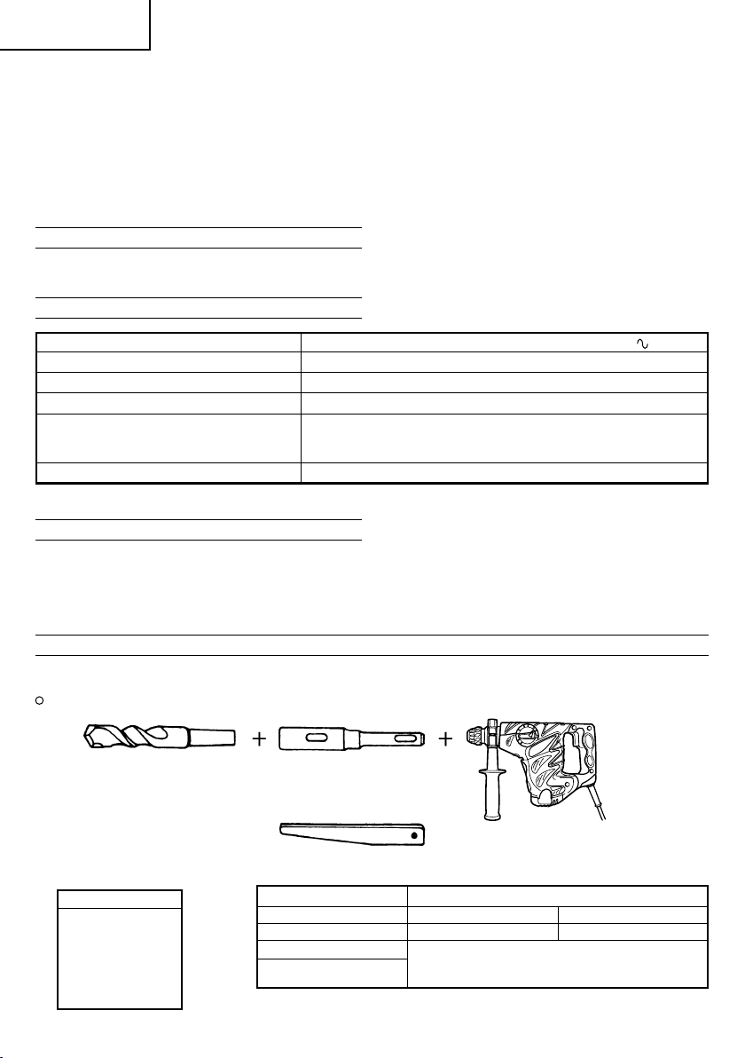
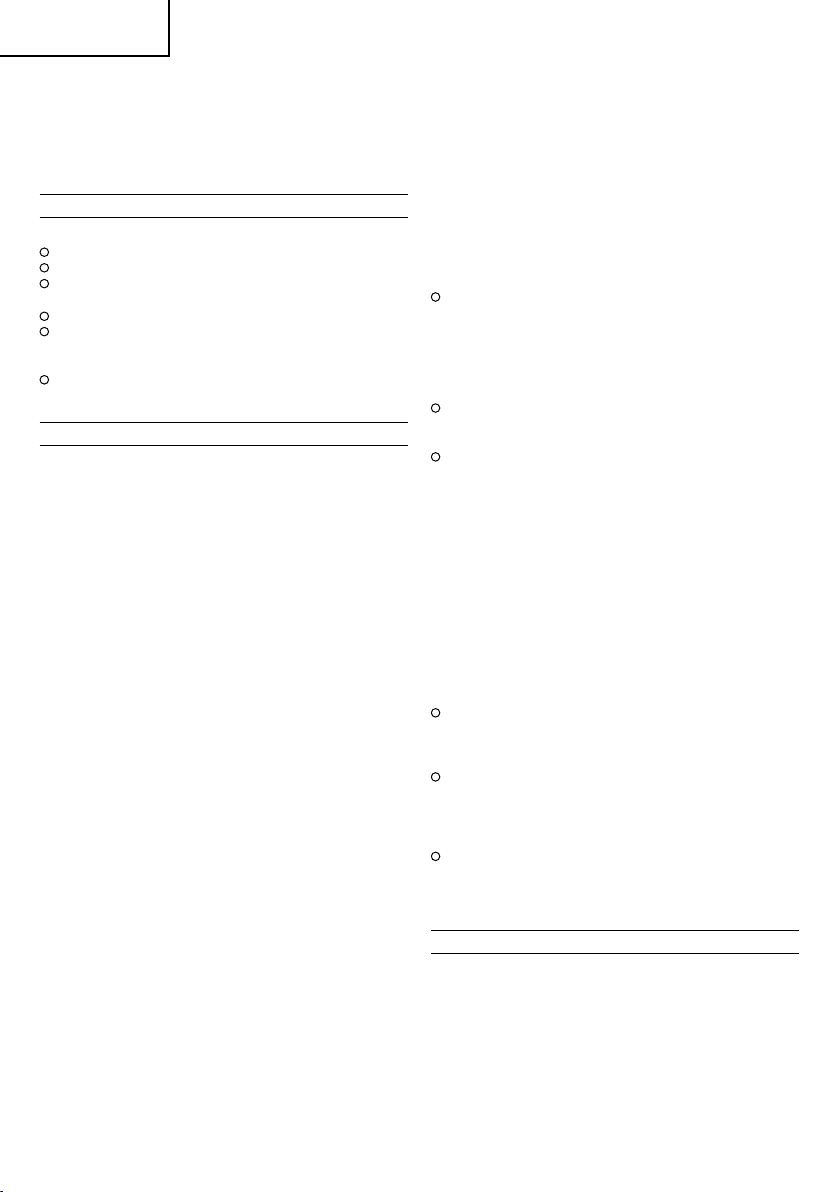
OPTIONAL ACCESSORIES (sold separately)
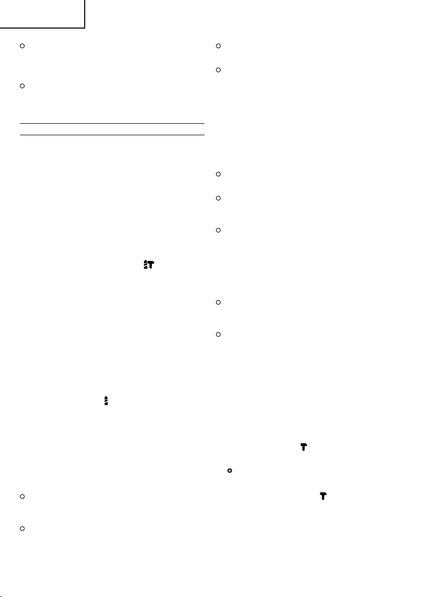
1. Drilling anchor holes (rotation + hammering)
Drill bit (Taper shank) and taper shank adapter
Drill bit (Taper shank)
Outer diameter
11.0 mm
12.3 mm
12.7 mm
14.3 mm
14.5 mm
17.5 mm
21.5 mm
7
Taper shank adapter
(SDS-plus shank)
Taper mode Applicable drill bit
Morse taper (No.1) Drill bit (taper shank) 11.0 ~ 17.5 mm
Morse taper (No.2) Drill bit (taper shank) 21.5 mm
A-taper Taper shank adapter formed A-taper or B-taper
B-taper
Cotter
is provided as an optional accessory, but the
drill bit for it is not provided.
Page 9
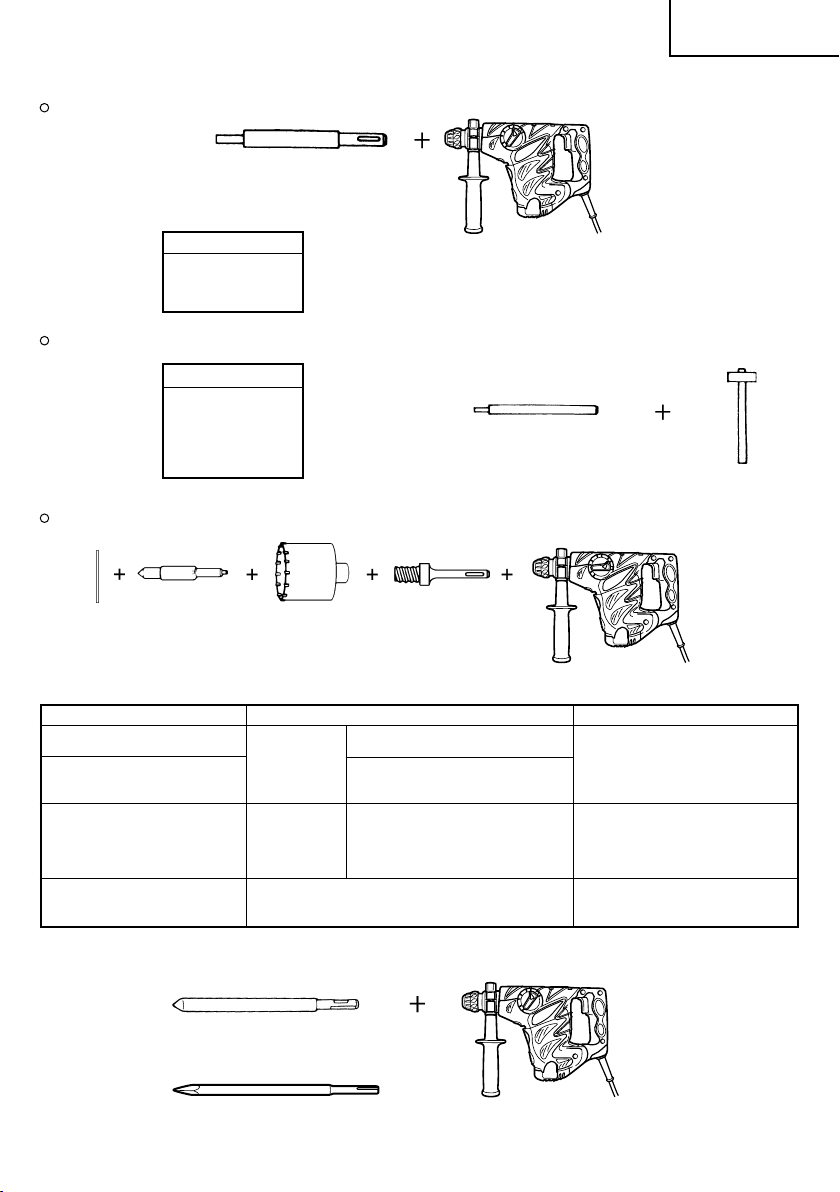
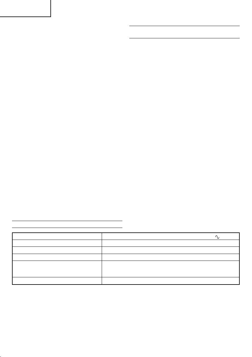
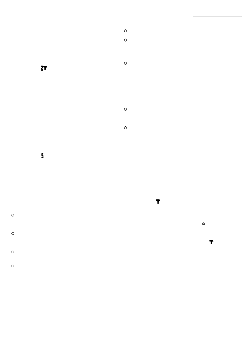
2. Anchor setting (hammering only)
Anchor setting adapter (for rotary hammer)
Anchor setting adapter (SDS-plus shank)
(for rotary hammer)
Overall length: 160, 260 mm
Anchor size
W1/4"
W5/16"
W3/8"
Anchor setting adapter (for manual hammer)
Anchor size
W1/4"
W5/16"
W3/8"
W1/2"
W5/8"
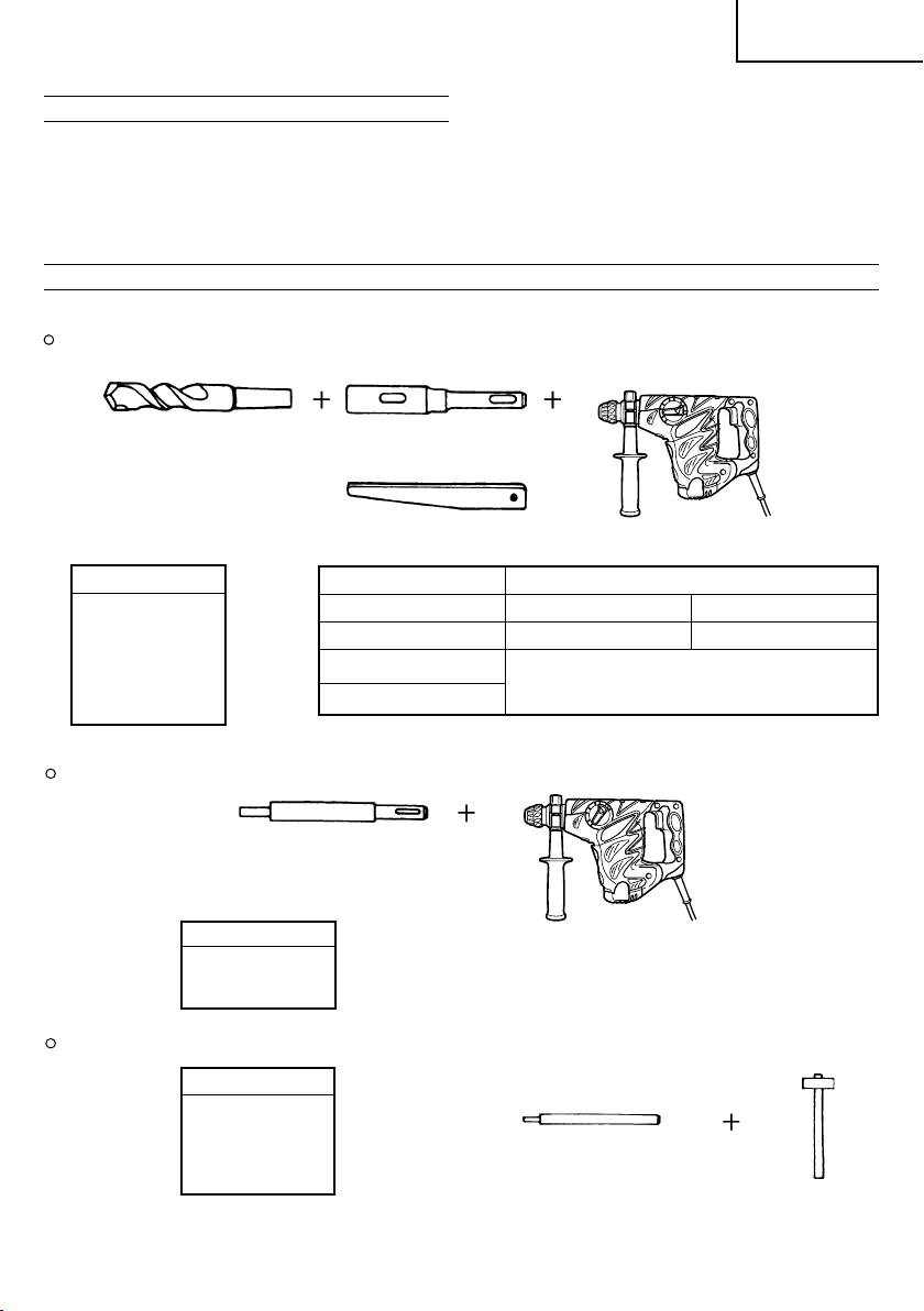
3. Large hole boring (rotation + hammering)
Center pin, core bit, core bit shank and guide plate.
English
Anchor setting adapter
(for manual hammer)
(Guide plate) Center pin Core bit Core bit shank
Center pin Core bit (outer diameter) Core bit shank
–
(A)
Center pin (A) 35 mm
Center pin (B) (B) 65 mm Core bit shank (B)
Do not use core bits with with guide plate
outer diameter of 25 mm (The guide plate is not equipped with core bits
and 29 mm. with outer diameter of 25 mm and 29 mm.)
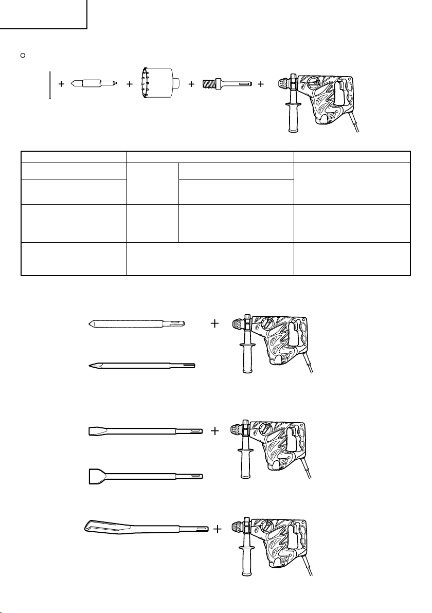
4. Demolishing operation (hammering only)
Bull point (Round type) (SDS-plus shank)
Bull point (Square type) (SDS-plus shank)
(SDS-plus shank)
25 mm
29 mm
32 mm Core bit shank (A)
38 mm
45 mm
50 mm
80 mm
90 mm
8
Page 10
English
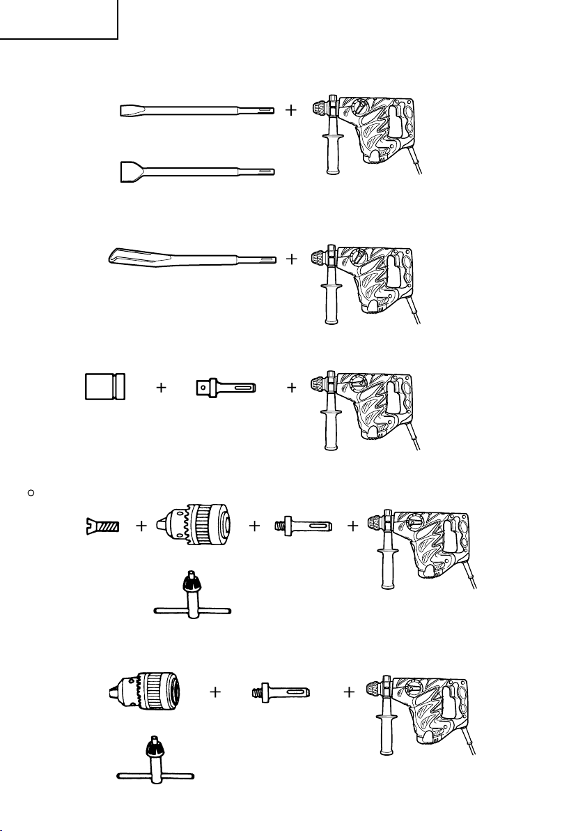
5. Groove digging and edging (Hammering only)
Cold chisel (SDS-plus shank)
Cutter (SDS-plus shank)
6. Grooving (Hammering only)
Grooving chisel (SDS-plus shank)
7. Bolt placing operation with Chemical Anchor (rotation + hammering)
Standard socket
( )
on the market
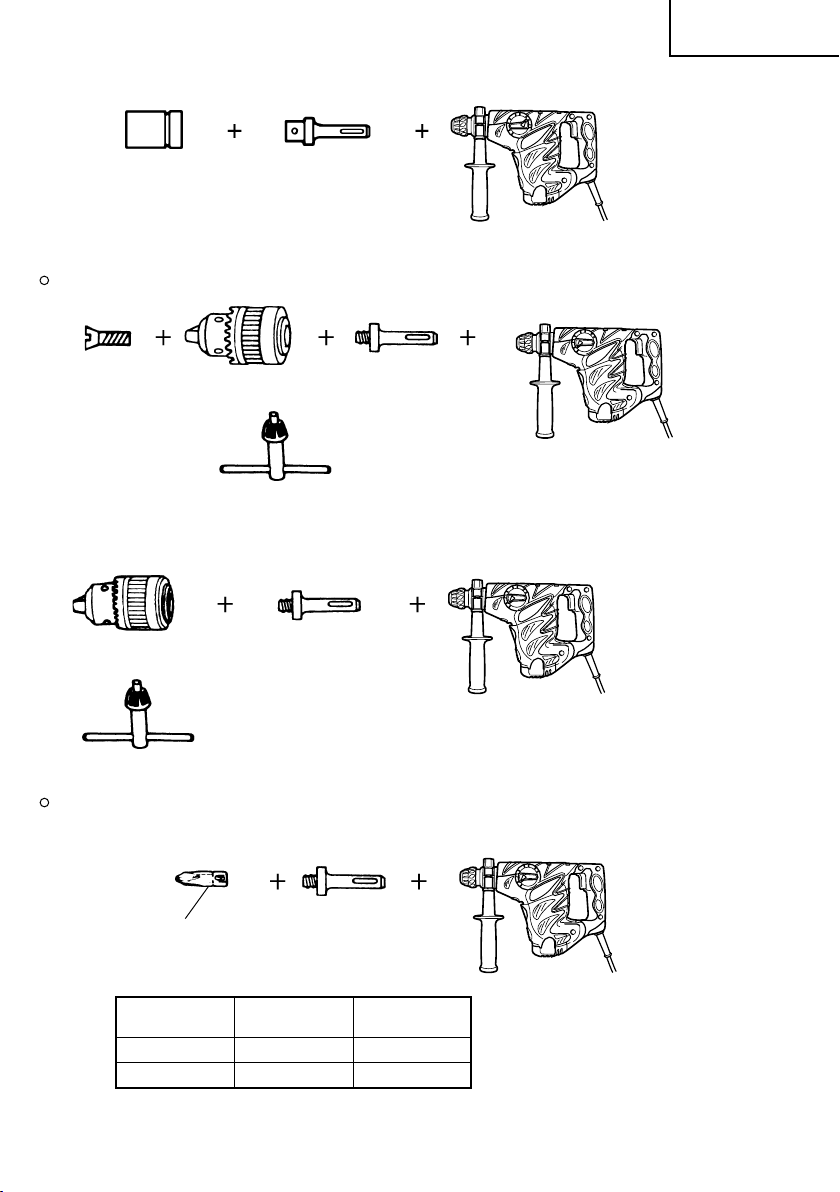
8. Drilling holes and driving screws (rotation only)
Drill chuck, chuck adapter (G), special screw and chuck wrench
9. Drilling holes (rotation only)
Drill chuck (13VLD-D)
9
12.7 mm Chemical Anchor Adapter
19 mm Chemical Anchor Adapter
Drill chuck (13VLRB-D)Special screw
Chuck wrench
Chuck wrench
(SDS-plus shank)
Chuck adapter (G)
(SDS-plus shank)
Chuck adapter (D)
(SDS-plus shank)
Page 11
13 mm drill chuck ass’y (includes chuck wrench) and chuck (for drilling in steel or wood).
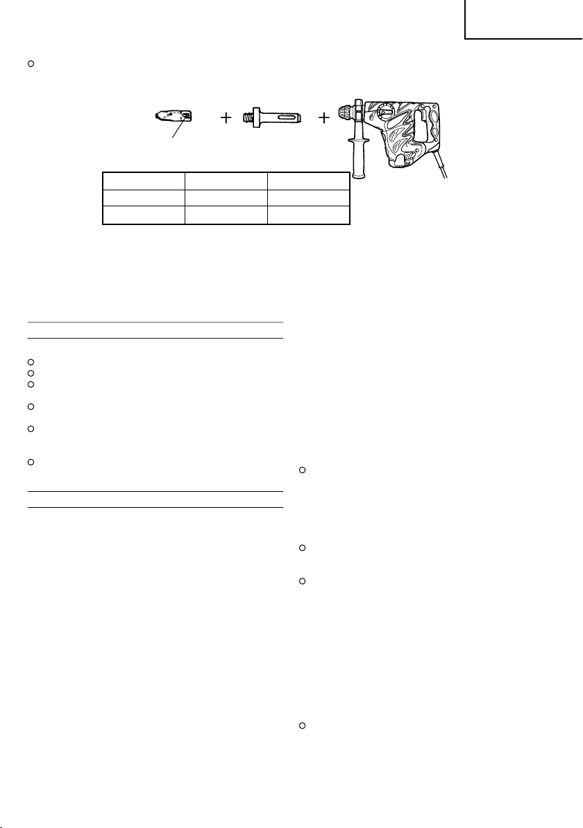
10. Driving Screws (rotation only)
English
Bit No.
Bit No. Screw Size Length
No. 2 3 – 5 mm 25 mm
No. 3 6 – 8 mm 25 mm
11. Hammer grease A
500 g (in a can)
70 g (in a green tube)
30 g (in a green tube)
Optional accessories are subject to change without notice.
Chuck adapter (D)
(SDS-plus shank)
APPLICATIONS
Rotation and hammering function
Drilling anchor holes
Drilling holes in concrete
Drilling holes in tile
Rotation only function
Drilling in steel or wood
(with optional accessories)
Tightening machine screws, wood screws
(with optional accessories)
Hammering only function
Light-duty chiselling of concrete, groove digging
and edging.
PRIOR TO OPERATION
1. Power source
Ensure that the power source to be utilized conforms
to the power requirements specified on the product
nameplate.
2. Power switch
Ensure that the power switch is in the OFF position.
If the plug is connected to a receptacle while the
power switch is in the ON position, the power tool
will start operating immediately, which could cause
a serious accident.
3. Extension cord
When the work area is removed from the power
source, use an extension cord of sufficient thickness
and rated capacity. The extension cord should be
kept as short as practicable.
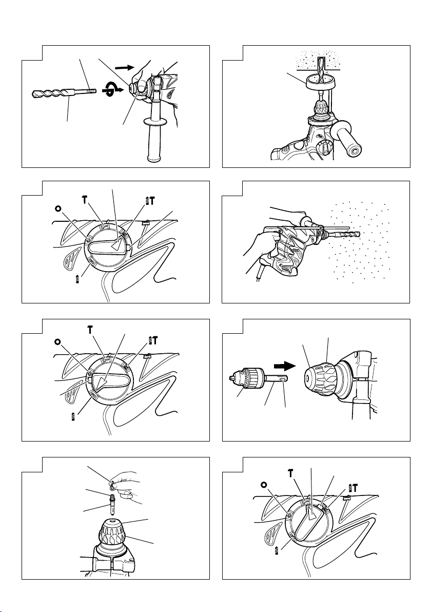
4. Mounting the drill bit (Fig. 1)
CAUTION
To prevent accidents, make sure to turn the switch
off and disconnect the plug from the receptacle.
NOTE
When using tools such as bull points, drill bits, etc.,
make sure to use the genuine parts designated by
our company.
(1) Clean the shank portion of the drill bit.
(2) To attach a drill bit (SDS-plus shank), fully pull the
grip in the direction of the arrow as shown in Fig.
1 and insert the drill bit as far as it will go while
manually turning.
(3) By releasing the grip, the drill bit will be secured.
(4) To remove the drill bit, fully pull the grip in the
direction of the arrow and pull out the drill bit.
5. Installation of dust cup (Optional accessories) (Fig.
2)
When using a rotary hammer for upward drilling
operations attach a dust cup to collect dust or
particles for easy operation.
Installing the dust cup
Use the dust cup by attaching to the drill bit as
shown in Fig. 2.
When using a bit which has big diameter, enlarge
the center hole of the dust cup with this rotary
hammer.
CAUTION:
The dust cup is for exclusive use of concrete drilling
work. Do not use them for wood or metal drilling
work.
Dump particles after every two or three holes when
drilling.
6. Selecting the driver bit
Screw heads or bits will be damaged should an
inappropriate bit for the screw diameter be employed
to drive in the screws.
7. Selecting the function mode
You can switch functions to the 3 modes of
“hammering only, “rotation + hammering”, and
“rotation only” by turning the change lever while
pressing the push button. Set the ▲ mark position
of the change lever to that of the mode to be used.
CAUTION:
Before operating the change lever, check and make
sure that the motor has stopped.
A failure can occur if it is operated while the motor
is running.
10
Page 12
English
To operate the change lever, press the push button,
and release the lock of the change lever. Also, check
and make sure after operation that the push button
has returned and that the change lever has been
locked.
Switch the change lever without mistake. If it is
used at a position halfway, there is a fear that the
service life of the switching mechanism may be
shortened.
HOW TO USE
CAUTION:
To prevent accidents, make sure to turn the switch off
and disconnect the plug from the receptacle when the
drill bits and other various parts are installed or removed.
The power switch should also be turned off during a
work break and after work.
1. Switch operation
The rotation speed of the drill bit can be controlled
steplessly by varying the amount that the trigger
switch is pulled. Speed is low when the trigger
switch is pulled slightly and increases as the switch
is pulled more.
2. Rotation + hammering
This rotary hammer can be set to rotation and
hammering mode by pressing the push button and
turning the change lever to the
Turn the grip slightly and confirm that the clutch
has been engaged with a click.
(1) Mount the drill bit.
(2) Pull the trigger switch after applying the drill bit
tip to the drilling position. (Fig. 4)
(3) Pushing the rotary hammer forcibly is not necessary
at all. Pushing slightly so that drill dust comes out
gradually is sufficient.
CAUTION:
When the drill bit touches construction iron bar, the
bit will stop immediately and the rotary hammer
will react to revolve. Therefore grip the side handle
and handle tightly as shown in Fig. 4.
3. Rotation only
This rotary hammer can be set to rotation only
mode by pussing the push button and turning the
change lever to the
Turn the grip slightly and confirm that the clutch
has been engaged with a click.
To drill wood or metal material using the drill chuck
and chuck adapter (optional accessories), proceed
as follows.
Installing drill chuck and chuck adapter: (Fig. 6)
(1) Attach the drill chuck to the chuck adapter.
(2) The part of the SDS-plus shank is the same as the
drill bit. Therefore, refer to the item of “Mounting
the drill bit” for attaching it.
CAUTIONS:
Application of force more than necessary will not
only expedite the work, but will deteriorate the tip
edge of the drill bit and reduce the service life of
the rotary hammer in addition.
Drill bits may snap off while withdrawing the rotary
hammer from the drilled hole. For withdrawing, it
is important to use a pushing motion.
mark. (Fig. 5)
mark (Fig. 3).
Do not attempt to drill anchor holes or holes in
concrete with the machine set in the rotation only
function.
Do not attempt to use the rotary hammer in the
rotation and hammering function with the drill chuck
and chuck adapter attached. This would seriously
shorten the service life of every component of the
machine.
4. When driving machine screws (Fig. 7)
First, insert the bit into the socket in the end of
chuck adapter (D).
Next, mount chuck adapter (D) on the main unit
using procedures described in 4 (1), (2), (3), put the
tip of the bit in the slots in the head of the screw,
grasp the main unit and tighten the screw.
CAUTIONS:
Exercise care not to excessively prolong driving
time, otherwise, the screws may be damaged by
excessive force.
Apply the rotary hammer perpendicularly to the
screw head when driving the screw; otherwise, the
screw head or bit will be damaged, or driving force
will not be fully transferred to the screw.
Do not attempt to use the rotary hammer in the
rotation and hammering function with the chuck
adapter and bit attached.
5. When driving wood screws (Fig. 7)
(1) Selecting a suitable driver bit
Employ cross-recessed screws, if possible, since the
driver bit easily slips off the heads of slotted-head
screws.
(2) Driving in wood screws
Prior to driving in wood screws, make pilot holes
suitable for them in the wooden board. Apply the
bit to the screw head grooves and gently drive the
screws into the holes.
After rotating the rotary hammer at low speed for
a while until the wood screw is partly driven into
the wood, squeeze the trigger more strongly to
obtain the optimum driving force.
CAUTION:
Exercise care in preparing a pilot hole suitable for
the wood screw taking the hardness of the wood
into consideration. Should the hole be excessively
small or shallow, requiring much power to drive
the screw into it, the thread of the wood screw may
sometimes be damaged.
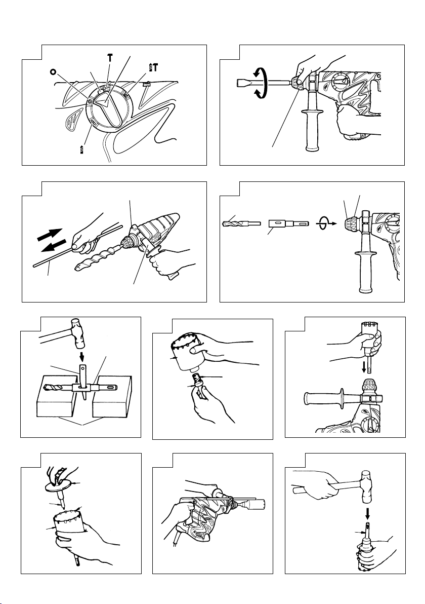
6. Hammering only
This rotary hammer can be set to hammering only
mode by pressing the push button and turning the
change lever to the
(1) Mount the bull point or cold chisel.
(2) Press the push button and set the change lever to
mark. (Fig. 9)
The rotation is released, turn the grip and adjust
the cold chisel to desired position. (Fig. 10)
(3) Turn the change lever to
Then bull point or cold chisel is locked.
7. Using the stopper (Fig. 11)
(1) Loosen the side handle, and insert the stopper into
the handle bolt hole.
(2) Adjust the stopper position according to the depth
of the hole and thighten the side handle securely.
mark (Fig. 8).
mark. (Fig. 8)
11
Page 13

English
8. How to use the drill bit (taper shank) and the taper
shank adapter
(1) Mount the taper shank adapter to the rotary hammer.
(Fig. 12)
(2) Mount the drill bit (taper shank) to the taper shank
adapter. (Fig. 12)
(3) Turn the switch ON, and drill a hole in prescribed
depth.
(4) To remove the drill bit (taper shank), insert the
cotter into the slot of the taper shank adapter and
strike the head of the cotter with a manual hammer
supporting on a rests. (Fig. 13)
9. Using the side handle
When you wish to change a position of the side
handle, turn grip of the side handle counterclockwise
to loosen it, and then fasten it firmly.
CAUTION:
When boring a hole, there can be a case where the
machine attempts to rotate by the reaction at the
time of penetrating a concrete wall and/or when a
tip of the blade comes in contact with the rebar.
Firmly fasten the side handle and hold the machine
with both of your hands. Unless you hold it securely,
an accident can occur.
HOW TO USE THE CORE BIT
(FOR LIGHT LOAD)
When boring penerating large holes use the core bit (for
light loads). At that time use with the center pin and the
core bit shank provided as optional accessories.
1. Mounting
CAUTION
Be sure to turn power OFF and disconnect the plug
from the receptacle.
(1) Mount the core bit to the core bit shank. (Fig. 14).
Lubricate the thread of the core bit shank to facilitate
disassembly.
(2) Mount the core bit to the rotary hammer (Fig. 15).
(3) Insert the center pin into the guide plate until it
stops.
(4) Engage the guide plate with the core bit, and turn
the guide plate to the left or the right so that it
does not fall even if it faced downward. (Fig. 16).
2. How to bore (Fig. 17)
(1) Connect the plug to the power source.
(2) A spring is installed in the center pin.
Push it lightly to the wall or the floor straight.
Connect the core bit tip flush to the surface and
start operating.
(3) When boring about 5 mm in depth the position of
the hole will be established. Bore after that removing
the center pin and the guide plate from core bit.
(4) Application of excessive force will not only expedite
the work, but will deteriorate the tip edge of the
drill bit, resulting in reduced service life of the
rotary hammer.
CAUTION
When removing the center pin and the guide plate,
turn OFF the switch and disconnect the plug from
the receptacle.
3. Dismounting (Fig. 18)
Remove the core bit shank from the rotary hammer
and strike the head of the core bit shank strongly
two or three times with a manual hammer holding
the core bit, then the thread becomes loose and
the core bit can be removed.
GREASE REPLACEMENT
This machine is full air-tight construction to protect
against dust incursion and to prevent lubricant leakage.
This machine can be used without grease replenishment
for an extended period of time. However, perform the
grease replacement to extend the service life. Replace
the grease as described below.
1. Grease Replacement Period
You should look at the grease when you change
the carbon brush. (See item 4 in the section
MAINTENANCE AND INSPECTION.)
Ask for grease replacement at the nearest authorized
Hitachi Service Center.
In the case that you are forced to change the grease
by yourself, please follow the following points.
2. How to replace grease
CAUTION:
Before replacing the grease, turn the power off and
pull out the plug from the receptacle.
(1) Disassemble the crank cover and thoroughly wipe
off the old grease inside. (Fig. 19)
(2) Supply 30g of Hitachi Electric Hammer Grease A
(standard accessory, contained in tube) in the crank
case.
(3) After replacing the grease, reassemble the crank
cover securely. At this time, do not damage or lose
the oil seal.
NOTE:
The Hitachi Electric Hammer Grease A is of the low
viscosity type. When the grease is consumed,
purchase from the authorized Hitachi Service
Center.
MAINTENANCE AND INSPECTION
1. Inspecting the drill bits
Since use of a dull tool will cause motor
malfunctioning and degraded efficiency, replace the
drill bit with new ones or resharpen them without
delay when abrasion is noted.
2. Inspecting the mounting screws:
Regularly inspect all mounting screws and ensure
that they are properly tightened. Should any of the
screws be loose, retighten them immediately. Failure
to do so could result in serious hazard.
3. Maintenance of the motor
The motor unit winding is the very heart” of the
power tool. Exercise due care to ensure the winding
does not become damaged and/or wet with oil or
water.
4. Inspecting the carbon brushes
For your continued safety and electrical shock
protection, carbon brush inspection and replacement
on this tool should ONLY be performed by a HITACHI
AUTHORIZED SERVICE CENTER.
12
Page 14

English
5. Replacing supply cord
If the supply cord of Tool is damaged, the Tool
must be returned to Hitachi Authorized Service
Center for the cord to be replaced.
6. Service parts list
A: Item No.
B: Code No.
C: No. Used
D: Remarks
CAUTION
Repair, modification and inspection of Hitachi Power
Tools must be carried out by an Hitachi Authorized
Service Center.
This Parts List will be helpful if presented with the
tool to the Hitachi Authorized Service Center when
requesting repair or other maintenance.
In the operation and maintenance of power tools,
the safety regulations and standards prescribed in
each country must be observed.
MODIFICATIONS
Hitachi Power Tools are constantly being improved
and modified to incorporate the latest technological
advancements.
Accordingly, some parts (i.e. code numbers and/or
design) may be changed without prior notice.
GUARANTEE
We guarantee Hitachi Power Tools in accordance with
statutory/country specific regulation. This guarantee does
not cover defects or damage due to misuse, abuse, or
normal wear and tear. In case of complaint, please send
the Power Tool, undismantled, with the GUARANTEE
CERTIFICATE found at the end of this Handling
instruction, to a Hitachi Authorized Service Center.
NOTE:
Due to HITACHI’s continuing program of research and
development, the specifications herein are subject to
change without prior notice.
IMPORTANT
Correct connection of the plug
The wires of the mains lead are coloured in accordance
with the following code:
Blue: -Neutral
Brown:-Live
As the colours of the wires in the mains lead of this tool
may not correspond with the coloured markings
identifying the terminals in your plug proceed as follows:
The wire coloured blue must be connected to the terminal
marked with the letter N or coloured black. The wire
coloured brown must be connected to the terminal
marked with the letter L or coloured red. Neither core
must be connected to the earth terminal.
NOTE:
This requirement is provided according to BRITISH
STANDARD 2769: 1984.
Therefore, the letter code and colour code may not be
applicable to other markets except The United Kingdom.
Information concerning airborne noise and vibration
The measured values were determined according to
EN60745 and declared in accordance with ISO 4871.
Measured A-weighted sound power level: 100 dB (A).
Measured A-weighted sound pressure level: 89 dB (A).
Uncertainty KpA: 3 dB (A).
Wear ear protection.
Vibration total values (triax vector sum) determined
according to EN60745.
Hammer drilling into concrete:
Vibration emission value
Uncertainty K = 1.9 m/s2 (A)
Chiselling:
Vibration emission value
Uncertainty K = 6.5 m/s2 (A)
No load:
Vibration emission value
Uncertainty K = 3.0 m/s2 (A)
Equivalent chiselling value:
Vibration emission value
Uncertainty K = 6.5 m/s2 (A)
WARNING
䡬 The vibration emission value during actual use of
the power tool can differ from the declared value
depending on the ways in which the tool is used.
䡬 To identify the safety measures to protect the
operator that are based on an estimation of exposure
in the actual conditions of use (taking account of
all parts of the operating cycle such as the times
when the tool is switched off and when it is running
idle in addition to the trigger time).
ah, HD = 19.8 m/s
ah, CH = 13.6 m/s
ah, NL = 4.2 m/s
ah, CHeq = 12.3 m/s
2
2
2
2
13
Page 15

Deutsch
ALLGEMEINE SICHERHEITSHINWEISE FÜR
ELEKTROGERÄTE
WARNUNG
Lesen Sie sämtliche Sicherheitshinweise und
Anweisungen durch
Wenn die Warnungen und Anweisungen nicht befolgt
werden, kann es zu Stromschlag, Brand und/oder
ernsthaften Verletzungen kommen.
Bitte bewahren Sie alle Warnhinweise und Anweisungen
zum späteren Nachschlagen auf.
Der Begriff „Elektrowerkzeug“ bezieht sich in den
Warnhinweisen auf Elektrowerkzeuge mit Netz(schnurgebunden) oder Akkubetrieb (schnurlos).
1) Sicherheit im Arbeitsbereich
a) Sorgen Sie für einen sauberen und gut
ausgeleuchteten Arbeitsbereich.
Zugestellte oder dunkle Bereiche ziehen Unfälle
förmlich an.
b) Verwenden Sie Elektrowerkzeuge niemals an
Orten, an denen Explosionsgefahr besteht – zum
Beispiel in der Nähe von leicht entflammbaren
Flüssigkeiten, Gasen oder Stäuben.
Bei der Arbeit mit Elektrowerkzeugen kann es
zu Funkenbildung kommen, wodurch sich Stäube
oder Dämpfe entzünden können.
c) Sorgen Sie bei der Arbeit mit Elektrowerkzeugen
dafür, dass sich keine Zuschauer (insbesondere
Kinder) in der Nähe befinden.
Wenn Sie abgelenkt werden, können Sie die
Kontrolle über das Werkzeug verlieren.
2) Elektrische Sicherheit
a) Elektrowerkzeuge müssen mit passender
Stromversorgung betrieben werden.
Nehmen Sie niemals irgendwelche Änderungen
am Anschlussstecker vor.
Verwenden Sie bei Elektrowerkzeugen mit
Schutzkontakt (geerdet) niemals Adapterstecker.
Stecker im Originalzustand und passende
Steckdosen reduzieren das Stromschlagrisiko.
b) Vermeiden Sie Körperkontakt mit geerdeten
Gegenständen wie Rohrleitungen, Heizungen,
Herden oder Kühlschränken.
Bei Körperkontakt mit geerdeten Gegenständen
besteht ein erhöhtes Stromschlagrisiko.
c) Setzen Sie Elektrowerkzeuge niemals Regen oder
sonstiger Feuchtigkeit aus.
Wenn Flüssigkeiten in ein Elektrowerkzeug
eindringen, erhöht sich das Stromschlagrisiko.
d) Verwenden Sie die Anschlussschnur nicht
missbräuchlich. Tragen Sie das Elektrowerkzeug
niemals an der Anschlussschnur, ziehen Sie es
nicht damit heran und ziehen Sie den Stecker
nicht an der Anschlussschnur aus der Steckdose.
Halten Sie die Anschlussschnur von Hitzequellen,
Öl, scharfen Kanten und beweglichen Teilen fern.
Beschädigte oder verdrehte Anschlussschnüre
erhöhen das Stromschlagrisiko.
e) Wenn Sie ein Elektrowerkzeug im Freien
benutzen, verwenden Sie ein für den
Außeneinsatz geeignetes Verlängerungskabel.
Ein für den Außeneinsatz geeignetes Kabel
vermindert das Stromschlagrisiko.
f) Falls sich der Betrieb des Elektrowerkzeuges in
feuchter Umgebung nicht vermeiden lässt,
verwenden Sie eine Stromversorgung mit
Fehlerstromschutzeinrichtung (Residual Current
Device, RCD).
Durch den Einsatz einer
Fehlerstromschutzeinrichtung wird das Risiko
eines elektrischen Schlages reduziert.
3) Persönliche Sicherheit
a) Bleiben Sie wachsam, achten Sie auf das, was
Sie tun, und setzen Sie Ihren Verstand ein,
wenn Sie mit Elektrowerkzeugen arbeiten.
Benutzen Sie keine Elektrowerkzeuge, wenn Sie
müde sind oder unter Einfluss von Drogen,
Alkohol oder Medikamenten stehen.
Bei der Arbeit mit Elektrowerkzeugen können
bereits kurze Phasen der Unaufmerksamkeit zu
schweren Verletzungen führen.
b) Benutzen Sie eine persönliche Schutzausrüstung.
Tragen Sie immer einen Augenschutz.
Schutzausrüstung wie Staubmaske, rutschsichere
Sicherheitsschuhe, Schutzhelm und Gehörschutz
senken das Verletzungsrisiko bei angemessenem
Einsatz.
c) Vermeiden Sie unbeabsichtigten Anlauf. Achten
Sie darauf, dass sich der Schalter in der Aus(Off-) Position befindet, ehe Sie das Gerät mit
der Stromversorgung und/oder
Batteriestromversorgung verbinden, es aufheben
oder herumtragen.
Das Herumtragen von Elektrowerkzeugen mit dem
Finger am Schalter oder das Herstellen der
Stromversorgung bei betätigtem Schalter zieht
Unfälle regelrecht an.
d) Entfernen Sie sämtliche Einstellwerkzeuge
(Einstellschlüssel), ehe Sie das Elektrowerkzeug
einschalten.
Ein an einem beweglichen Teil des Elektrowerkzeugs
angebrachter Schlüssel kann zu Verletzungen führen.
e) Sorgen Sie für einen festen Stand. Achten Sie
jederzeit darauf, sicher zu stehen und das
Gleichgewicht zu bewahren.
Dadurch haben Sie das Elektrowerkzeug in
unerwarteten Situationen besser im Griff.
f) Kleiden Sie sich richtig. Tragen Sie keine lose
Kleidung oder Schmuck. Halten Sie Haar, Kleidung
und Handschuhe von beweglichen Teilen fern.
Lose Kleidung, Schmuck oder langes Haar kann
von beweglichen Teilen erfasst werden.
g) Wenn Anschlüsse für Staubabsaug- und -
sammelvorrichtungen vorhanden sind, sorgen
Sie dafür, dass diese richtig angeschlossen und
eingesetzt werden.
Durch Entfernen des Staubes können
staubbezogene Gefahren vermindert werden.
4) Einsatz und Pflege von Elektrowerkzeugen
a) Überanspruchen Sie Elektrowerkzeuge nicht.
Benutzen Sie das richtige Elektrowerkzeug für
Ihren Einsatzzweck.
Das richtige Elektrowerkzeug erledigt seine Arbeit
bei bestimmungsgemäßem Einsatz besser und
sicherer.
b) Benutzen Sie das Elektrowerkzeug nicht, wenn es
sich nicht am Schalter ein- und ausschalten lässt.
Jedes Elektrowerkzeug, das nicht mit dem
Schalter betätigt werden kann, stellt eine Gefahr
dar und muss repariert werden.
c) Stecken Sie den Stecker der Stromversorgung
oder Batteriestromversorgung vom Gerät ab,
ehe Sie Einstellarbeiten vornehmen, Zubehörteile
tauschen oder das Elektrowerkzeug verstauen.
Solche präventiven Sicherheitsmaßnahmen
verhindern den unbeabsichtigten Anlauf des
Elektrowerkzeugs und die damit verbundenen
Gefahren.
14
Page 16
Deutsch
d) Lagern Sie nicht benutzte Elektrowerkzeuge
außerhalb der Reichweite von Kindern, lassen
Sie nicht zu, dass Personen das Elektrowerkzeug
bedienen, die nicht mit dem Werkzeug selbst
und/oder diesen Anweisungen vertraut sind.
Elektrowerkzeuge in ungeschulten Händen sind
gefährlich.
e) Halten Sie Elektrowerkzeuge in Stand. Prüfen
Sie auf Fehlausrichtungen, sicheren Halt und
Leichtgängigkeit beweglicher Teile,
Beschädigungen von Teilen und auf jegliche
andere Zustände, die sich auf den Betrieb des
Elektrowerkzeugs auswirken können.
Bei Beschädigungen lassen Sie das
Elektrowerkzeug reparieren, ehe Sie es benutzen.
Viele Unfälle mit Elektrowerkzeugen sind auf
schlechte Wartung zurückzuführen.
f) Halten Sie Schneidwerkzeuge scharf und sauber.
Richtig gewartete Schneidwerkzeuge mit scharfen
Schneidkanten bleiben weniger häufig hängen
und sind einfacher zu beherrschen.
g) Benutzen Sie Elektrowerkzeuge, Zubehör,
Werkzeugspitzen und Ähnliches in
Übereinstimmung mit diesen Anweisungen –
beachten Sie dabei die jeweiligen
Arbeitsbedingungen und die Art und Weise der
auszuführenden Arbeiten.
Der Gebrauch des Elektrowerkzeuges für andere
als die vorgesehenen Anwendungen kann zu
gefährlichen Situationen führen.
5) Service
a) Lassen Sie Elektrowerkzeuge durch qualifizierte
Fachkräfte und unter Einsatz passender,
zugelassener Originalteile warten.
Dies sorgt dafür, dass die Sicherheit des
Elektrowerkzeugs nicht beeinträchtigt wird.
VORSICHT
Von Kindern und gebrechlichen Personen fernhalten.
Werkzeuge sollten bei Nichtgebrauch außerhalb der
Reichweite von Kindern und gebrechlichen Personen
aufbewahrt werden.
VORSICHTSMASSNAHMEN BEI BENUTZUNG
DES BOHRHAMMERS
1. Ohrenschutz tragen.
Wenn Sie Lärm ausgesetzt sind, kann dies zu
einem Gehörverlust führen.
2. Verwenden Sie die mit dem Werkzeug gelieferten
Hilfsgriffe.
Wenn Sie die Kontrolle über das Werkzeug
verlieren, kann dies zu Personenschaden führen.
3. Berühren Sie die Bohrerspitze während oder
unmittelbar nach dem Betrieb nicht. Die
Bohrerspitze wird während des Betriebs sehr heiß,
sodass es zu ernsthaften Verbrennungen kommen
könnte.
4. Überzeugsen Sie sich, bevor Sie an der Wand, im
Boden oder an der Decke etwas ausbrechen,
meißeln oder bohren, sorgfältig davon, dass keine
elektrischen Kabel oder Kabelrohre darunter liegen.
5. Halten Sie den Gehäuse- und Seitengriff des
Elektrowerkzeugs immer gut fest. Andernfalls kann
die entstehende Gegenkraft zu einem ungenauen
und gefährlichen Arbeiten führen.
6. Tragen Sie eine Staubmaske.
Inhalieren Sie nicht den schädlichen Staub, der
bei Bohr- oder Meißelarbeiten entsteht. Der Staub
kann Ihre Gesundheit und die von Zuschauern
gefährden.
TECHNISCHE DATEN
Spannung (je nach Gebiet)* (110 V, 115 V, 120 V, 127 V, 220 V, 230 V, 240 V)
Leistungsaufnahme 850 W*
Leerlaufdrehzahl 0 – 850 min
Vollastschlagzahl 0 – 3700 min
Kapazität: Beton 4 – 30 mm
Gewicht (ohne Kabel und Handgriff) 4,3 kg
*Vergessen Sie nicht, die Produktangaben auf dem Typenschild zu überprüfen, da sich diese je nach Verkaufsgebiet
ändern.
15
Stahl 13 mm
Holz 32 mm
-1
-1
Page 17
STANDARDZUBEHÖR
(1) Plastikkoffer ................................................................ 1
(2) Handgriff ..................................................................... 1
(3) Anschlagstange .......................................................... 1
(4) Staubschale ................................................................ 1
(5) Spritze ......................................................................... 1
Das Standardzubehör kann ohne vorherige
Bekanntmachung jederzeit geändert werden.
SONDERZUBEHÖR (separat zu beziehen)
1. Bohren von Verankerungslöchern (Bohren und Hammer)
Bohrer (Kegelschaft) und Konusschaftadapter
Deutsch
Bohrer (Kegelschaft) Konusschaftadapter
Außendurchmesser
11,0 mm
12,3 mm
12,7 mm
14,3 mm
14,5 mm
17,5 mm
21,5 mm
2. Verankerungseinsatz (nur Hammer)
Adapter für Ankerbefestigung (für Bohrhammer)
Adapter für Ankerbefestigung (SDS-Plus Schaft)
(für Bohrhammer)
Gesamtlänge: 160 mm 260 mm
Ankergröße
W1/4"
W5/16"
W3/8"
Adapter für Ankerbefestigung (mit dem Handhammer)
(SDS-Plus Schaft)
Dorn
Konusschaftadapter Anwendbarer Bohrer
Morsekonus (Nr.1) Bohrer (Konusschaft) 11,0 ~ 17,5 mm
Morsekonus (Nr.2) Bohrer (Konusschaft) 21,5 mm
A-Konus
B-Konus der passende Bohrer separat zu beziehen.
Der Konusschaftadapter in der Form des A-oder
B-Konus wird nach Wunsch geliefert, doch ist
Ankergröße
W1/4"
W5/16"
W3/8"
W1/2"
W5/8"
Adapter für Ankerbefestigung
(mit dem Handhammer)
16
Page 18
Deutsch
3. Lochbohren mit weitem Durchmesser (Bohren und Hammer)
Mittelstift, Bohrkrone, Bohrkronenschenkel und Führungsplatte.
(Führungsplatte) Mittelstift Bohrkrone Bohrkronenschenkel
Mittelstift Bohrkre (Außendurchmesser) Bohrkronenzapfen
–
Mittelstift (A)
Mittelstift (B) (B) 65 mm Bohrkronenzapfen (B)
Niemals Bohrkronen mit Mit Führungsplatte (Die Führungsplatte ist
einem Außendurchmesser nicht für Bohrkronen mit einem
von 25 mm oder 29 mm Außendurchmesser von 25 mm
verwenden. oder 29 mm besitzen.)
4. Aufbrecharbeiten (nur Hammer)
Spitzmeißel (Runder Typ) (SDS-Plus Schaft)
Spitzmeißel (viereckig) (SDS-Plus Schaft)
5. Nuten und kanten (nur Hammer)
Kaltmeißel (SDS-Plus Schaft)
(A)
(SDS-Plus Schaft)
25 mm
29 mm
32 mm Bohrkronenzapfen (A)
35 mm
38 mm
45 mm
50 mm
80 mm
90 mm
Spatmeißel (SDS-Plus Schaft)
6. Auskehlung (nur Hammer)
Nutenmeißel (SDS-Plus Schaft)
17
Page 19
7. Bolzenplatzierung mit Klebeanker (Bohren und Hammer)
Deutsch
Sockel auf
( )
markierter stelle
8. Löcherbohren und schneidschraube (nur Drehung)
Bohrfutter, Bohrfutteradapter (G), Spezialschraube und Bohrfutterschlüssel
Spezialschraube
9. Löcherbohren (nur Drehung)
Bohrfutter (13 VLD-D)
12,7 mm Adapter für Chemical Anchor
19 mm Adapter für Chemical Anchor
Bohrfuter (13 VLRB-D)
Bohrffutterschlüssel
(SDS-Plus Schaft)
Bohrfutteradapter (G)
(SDS-Plus Schaft)
Bohrfutteradapter (D)
(SDS-Plus Schaft)
Bohrfutterschlüssel
Zum Bohren von Stahl oder Holz: Bohrfuttervorrichtung von 13 mm (einschl Futterschlüssel), Futteradapter.
10. Schneidschraube (nur Drehung)
Bohrespitzennummer
Bohrerspitzen-
nummer
Nr.2 3 - 5 mm 25 mm
Nr.3 6 - 8 mm 25 mm
Bohrfutteradapter (D)
(SDS-Plus Schaft)
Schraubengröße Länge
18
Page 20
Deutsch
11. Hammer Schmierfett A
500 g (Dose)
70 g (in grüner Tube)
30 g (in grüner Tube)
Das Sonderzubehöre kann ohne vorherige Bekanntmachung jederzeit geändert werden.
ANWENDUNGEN
Bohr- und Hammerfunktion
Bohren von Ankerlöchern
Bohren von Löchern in Beton
Bohren von Löchern in Kachel
Nur Drehbohrfunktion
Bohren in Stahl oder Holz (mit Sonderzubehör)
Anziehen von Maschinenschrauben, Holzschrauben.
(mit Sonderzubehör)
Nur Hammerfunktion
Leichtes Auskehlen von Beton, Herstellen von Nuten
und Besäumen.
VOR INBETRIEBNAHME
1. Netzspannung
Prüfen, daß die zu verwendende Netzspannung der
Angabe auf dem Typenschild entspricht.
2. Netzschalter
Prüfen, daß der Nezschalter auf „AUS” steht. Wenn
der Stecker an das Netz angeschlossen wird,
während der Schalter auf „EIN” steht, beginnt das
Werkzeug sofort zu laufen, was gefährlich ist.
3. Verlängerungskabel
Wenn der Arbeitsbereich nicht in der Nähe des
Netzanschlusses liegt, ist ein Verlängerungskabel
ausreichenden Querschnitts und ausreichender
Nennleistung zu verwenden. Das Verlängerungskabel
sollte so kurz wie möglich gehalten werden.
4. Anbringung des Bohrers (Abb. 1)
ACHTUNG
Um Unfälle zu vermeiden, stellen Sie sicher, dass
sich der Schalter in der Aus-Position befindet und
der Netzstecker aus der Netzsteckdose gezogen wird.
HINWEIS
Wenn Sie Werkzeuge wie Spitzmeißel, Bohrerspitzen
usw. verwenden, stellen Sie sicher, dass es sich um
die durch unser Unternehmen bezeichneten
Originalteile handelt.
(1) Reinigen Sie den Schaftabschnitt der Bohrerspitze.
(2) Zum Anbringen des Bohrers (SDS-Plus Schaft) gen
Griff ganz in Pfeilrichtung ziehen, wie in Abb. 1
gezeigt, und den Bohrer drehend ganz bis zum
Anschlag einsetzen.
(3) Den Griff loslassen, und der Bohrer ist befestigt.
(4) Zum Entfernen des Bohrers den Griff in Pfeilrichtung
ziehen, und den Bohrer herausziehen.
5. Montage der Staubschale (optionales Zubehör)
(Abb. 2)
Wenn ein Bohrhammer zum Bohren nach oben
verwendet wird, bringen Sie eine Stauschale an, um
Staub und Partikel zum leichteren Betrieb
aufzufangen.
Anbringen der Staubschale
Die Staubschale durch Anbringen an die Bohrspitze
wie in Abb. 2 gezeigt verwenden.
Bei Bohrspitzen mit großem Durchmesser das
Mittenloch der Staubschale mit diesem Bohrhammer
vergrößern.
ACHTUNG:
Die Staubschale ist nur für Bohrarbeiten in Beton
gedacht. Verwenden Sie sie nicht für Bohrarbeiten
in Holz oder Metall.
Leeren Sie den Staubfang jeweils nach dem Bohren
von zwei oder drei Löchern.
6. Wahl der Schrauberspitze
Wenn keine dem Schraubendurchmesser
angemessene Schrauberspitze zum Einschrauben
von Schrauben verwendet wird, kann es zu
Beschädigung des Schraubenkopfes bzw. der
Schrauberspitze kommen.
7. Wahl der Funktionsart
Sie können durch Drehen des Umschalthebels bei
gleichzeitigem Drücken des Druckknopfes zwischen
den drei Funktionsarten „nur Hammer“, „Bohren
und Hammer“ und „nur Bohren“ umschalten. Stellen
Sie den Umschalthebel auf die ▲ Markierung für
den zu verwendenden Modus.
ACHTUNG:
Stellen Sie vor Betätigung des Umschalthebels
sicher, dass der Motor angehalten hat.
Betätigung bei laufendem Motor kann Ausfall
verursachen.
Drücken Sie zum Betätigen des Umschalthebels den
Druckknopf, um die Verriegelung des
Umschalthebels freizugeben. Stellen Sie nach der
Betätigung sicher, dass der Druckknopf zurückgekehrt
ist und der Umschalthebel wieder verriegelt ist.
Schalten Sie den Umschalthebel korrekt um. Bei
Verwendung in einer Zwischenstellung ist zu
befürchten, dass die Lebensdauer des
Schaltmechanismus verringert wird.
GEBRAUCHSANWEISUNG
ACHTUNG:
Um Unfälle zu vermeiden, stellen Sie sicher, dass sich
der Schalter in der Aus-Position befindet und der
Netzstecker aus der Netzsteckdose gezogen wird, wenn
die Bohrerspitzen und andere Zubehörteile angebracht
oder entfernt werden. Der Netzschalter sollte auch
während einer Arbeitspause und nach der Arbeit
ausgeschaltet werden.
19
Page 21
Deutsch
1. Betätigung des Schalters
Die Drehzahl des Bohrers kann durch Veränderung
des Drucks auf den Drückerschalter gesteuert
werden. Die Geschwindigkeit ist gering, wenn der
Drückerschalter nur leicht gezogen ist und erhöht
sich, wenn der Schalter weiter durchgezogen wird.
2. Bohren und Hammer
Dieser Bohrhammer kann durch Druck auf den
Druckknopf und Drehen des Umschalthebels auf die
Markierung
werden (Abb. 3). Drehen Sie den Griff leicht und
stellen Sie sicher, dass die Kupplung hörbar
eingerastet ist.
(1) Die Bohrerspitze anbringen.
(2) Den Triggerschalter nach Anbringen in Bohrlage
der Bohrerspitze ziehen. (Abb. 4)
(3) Es ist nicht nötig den Bohrhammer stark
anzudrücken. Leichtes Andrücken, so daß der
Bohrstaub regelmäßig herausfällt, ist gerade
genügend.
ACHTUNG:
Wenn der Bohrer mit Baueisenstangen in Berührung
kommt, stoppt sofort der Bohren, und nur der
Bohrhammer dreht sich. Deshalb den Handgriff gut
fest halten wie in Abb. 4 gezeigt.
3. Nur Drehbohren
Dieser Bohrhammer kann durch Druck auf den
Druckknopf und Drehen des Umschalthebels zur
Markierung
werden. (Abb. 5)
Drehen Sie den Griff leicht und stellen Sie sicher,
dass die Kupplung hörbar eingerastet ist.
Zum Bohren von Holz und Metall einen
Bohrfutteradapter und ein Bohrfutter (zubehör)
verwenden. Anbringung des Bohrfutters und
Bohrfutteradapters: (Abb. 6)
Bringen Sie das Bohrfutter am Bohrfutteradapter an.
(1)
(2) Das Teil des SDS-Plus Schaftes ist das gleiche wie
der Bohrer. Zum Anbringen deshalb auf den Punkt
„Anbringung des Bohrers“ beziehen.
ACHTUNG:
Übermäßiger Druck wird nicht die Arbeit
beschleunigen und kann dazu die Bohrerleistung
und auch die Lebensdauer des Bohrhammers
vermindern.
Bohrerspitzen können abbrechen, wenn der
Bohrhammer aus dem gebohrten Loch herausgezogen
wird. Beim Herausziehen ist es wichtig, dies mit
einer drückenden Bewegung zu tun.
Nicht versuchen Ankerlöcher oder gewöhnliche
Löcher in Beton zu bohren, wenn das Werkzeug nur
auf Drehbohrfunktion eingestellt ist.
Versuchen Sie nicht, den Bohrhammer in der Bohr-
und Hammerfunktion zu verwenden, wenn das
Bohrfutter und der Bohrfutteradapter angebracht
sind.
4. Einschrauben von Maschinenschrauben (Abb. 7)
Zuerst die Drehspitze in den Sockel am Ende des
Futteradapters (D) einsetzen.
Dann den Futteradapter (D) mit dem in 4 (1), (2),
(3) beschriebenen Verfahren an die Haupteinheit
anbringen, die Spitze des Drehstücks in die Schlitze
auf dem Schraubenkopf setzen, die Haupteinheit
fest greifen und die Schrauben festziehen.
auf Bohren und Hammer eingestellt
auf Betrieb nur für Bohren eingestellt
ACHTUNG:
Nicht mehr als nötig die Schraubzeit verlängern, um
Beschädigung der Schrauben zu vermeiden.
Den Bohrhammer senkrecht beim Einschrauben einer
Schraube an den Schraubenkopf ansetzen; sonst
könnte der Schraubenkopf oder die Bohrerspitze
beschüdigt werden, oder die Antriebskraft mag nicht
volkommen der Schraube übertragen werden.
Versuchen Sie nicht, den Bohrhammer in der Bohrund Hammerfunktion zu verwenden, wenn der
Bohrfutteradapter und die Bohrerspitze angebracht
sind.
5. Einschrauben von Holzschrauben (Abb. 7)
(1) Wahl einer passenden Bohrerspitze
So sehr wie möglich Kreuzkopfschrauben verwenden
da die Bohrerspitze leicht von gewöhnlichen
Schraubenköpfen abrutscht.
(2) Eischrauben
Vor dem Einschrauben von Holzschrauben, passende
Löcher im Holz orbereiten. Die Bohrerspitze an die
Schraubenkopfspalten ansetzen und die Schraube
sanft ins Holz einschrauben.
Nachdem sich der Bohrerhammer bei kleiner
Geschwindigkeit für eine Weile gedrecht hat bis die
Schraube zum Teil eingeschraubt wurde, fester auf
den Trigger drücken um optimale Antriebskraft zu
erreichen.
ACHTUNG:
Gut darauf achten, daß die Vorbereitung eines
passenden Loches für die Schraube gemäß der
Härte des Holzes durchgeführt wird. Falls das Loch
zu klein oder nicht tief genung sein sollte, und
dadurch große Kraftanwendung zum Einschrauben
erforderlich wird, kann das Schraubengewinde
manchmal beschädigt werden.
6. Nur Hammer
Dieser Bohrhammer kann durch Druck auf den
Druckknopf und Drehen des Umschalthebels auf die
Markierung
eingestellt werden (Abb. 8).
(1) Bringen Sie den Spitzmeißel oder einen anderen
Meißel an.
(2) Drücken Sie den Druckknopf und stellen Sie den
Umschalthebel auf die Markierung
Die Drehung wird dann freigegeben, und Sie können
den Griff drehen und den Meißel auf die gewünschte
Position einstellen. (Abb. 10)
(3) Drehen Sie den Umschalthebel zur Position (Abb. 8).
Der Spitzmeißel ist dann verriegelt.
7. Verwendung des Anschlags (Abb. 11)
(1) Den Seitenhandgriff lösen und den Anschlag in das
Handgriffschraubenloch einschieben.
(2) Den Anschlag entsprechend der Tiefe des Lochs
einstellen und den Seitenhandgriff sicher anziehen.
8. Benutzung des Bohrers (Kegelschafts) und des
Kegelschaftadapters
(1) Den Kegelschaftadapter am Bohrhammer anbringen
(Abb. 12).
(2) Den Bohrer (Kegelschaft) am Kegelschaftadapter
anbringen. (Abb. 12)
(3) Den Schalter einschalten und ein Loch mit der
vorgegebenen Tiefe bohren.
(4) Zur Entferung des Bohrers (Kegelschafts) einen Dorn
in den Schlitz des Kegelschaftadapters einführen
und mit einem Hammer gestüzt durch eine Auflage
auf den Kopf des Dorns schlagen (Abb. 13)
auf den Modus „nur Hammer“
. (Abb. 9)
20
Page 22

Deutsch
9. Verwendung des Seitenhandgriffs
Wenn Sie die Position des Seitenhandgriffs ändern
möchten, so drehen Sie den Seitenhandgriff gegen
den Uhrzeigersinn, um ihn zu lösen, und ziehen Sie
ihn dann in der neuen Position fest an.
ACHTUNG:
Beim Bohren kann es vorkommen, dass die
Reaktionskraft beim Durchdringen durch eine
Betonwand oder bei Kontakt des Bohrers mit einer
Bewehrungsstange versucht, die Maschine zu
drehen.
Ziehen Sie den Seitenhandgriff fest an und halten
Sie die Maschine mit beiden Händen. Wenn Sie die
Maschine nicht fest halten, kann es zu Unfällen
kommen.
BENUTZUNG DER BOHRKRONE
(FÜR GERINGE BELASTUNG)
Zur Bohrung großer Löcher eine Bohrkrone verwenden
(geringe Belastung). Dafür muß der Zentriestift und
Bohrkronenzapfen (beides Sonderzubehör) verwendet
werden.
1. Anbringen
ACHTUNG
Vor dem Anbringen das Gerät ausschalten und von
der Steckdose trennen.
(1) Die Bohrkrone am Bohrkronenzapfen anbringen
(Abb. 14). Für die Entfernung das Gewinde des
Bohrkronenzapfens schmieren.
(2) Den Bohrkronenzapfen am Bohrhammer anbringen
(Abb. 15).
(3) Den Zentrierstift vollständig bis zum Anschlag in die
Führungsplatte einführen.
(4) Dann die Führungsplatte in die Bohrkrone einsetzen
und nach links oder rechts drehen, sodaß sie nicht
herausfällt, wenn sie nach unten zeigt. (Abb. 16)
2. Bohrung (Abb. 17)
(1) Den Stecker an die Steckdose anschließen.
(2) Der Zentrierstift ist mit einer Feder versehen. Drücken
Sie diese Feder geradlinig leicht gegen die Wand
oder den Boden. Die Fläche mit der Bohrkronenspitze
abtasten und das Gerät einschalten.
(3) Wenn eine Bohrtiefe von 5 mm erreicht worden ist,
ist die Position des Bohrlochs fixiert. Dann nach
Entfernung des Zentrierstifts und der Führungsplatte
von der Bohrkrone mit der Bohrung beginnen.
(4) Wenn beim Bohren übermäßige Gewalt angewandt
wird, wird der Bohrzapfenrand der Bohrkrone
beschädigt, wodurch die Lebensdauer des
Bohrhammers verkürzt wird.
ACHTUNG
Vor der Entfernung des Zentrierstifts und der
Führungsplatte das Gerät ausschalten und von der
Steckdose trennen.
3. Entfernung (Abb. 18)
Für die Entfernung kann ebenfalls ein anderes
Verfahren angewandt werden. Den
Bohrkronenzapfen vom Bohrhammer eintfernen und
mit einem Hammer mehrmals kräftig auf den Kopf
des Bohrkronenzapfens schlagen. Dabei sollte
allerdings die Bohrkrone festgehalten werden. Dann
löst sich das Gewinde und die Bohrkrone kann
abgenommen werden.
SCHMIERFETTWECHSEL
Dieses Gerät ist vollständig luftdicht gebaut, um es vor
dem Eintritt von Staub zu schützen und das Entweichen
von Schmiermittel zu verhindern. Dieses Gerät kann lange
Zeit ohne Nachfüllen von Fett verwendet werden. Füllen
Sie jedoch Fett nach, um die Verwendungszeit des
Gerätes zu verlängern. Zum Schmierfettwechsel wie
unten angegeben vorgehen.
1. Wechselzeit
Inspizieren Sie beim Auswechseln der Kohlebürsten
die Fettmenge. (Siehe Punkt 4 im Abschnitt „Wartung
und Inspektion”.) Wenden Sie sich an Ihre Hitachi
Service Station, um den Fettwechsel auszuführen.
Wenn Sie das Schmierfett selber wechseln müssen,
beachten Sie die folgenden Punkte.
2. Schmierfettwechsel
ACHTUNG:
Vor dem Schmierfettwechsel die Maschine
abschalten und den Netzstecker herausnehmen.
(1) Den Kurbeldeckel ausbauen und das alte Fett
gründlich vom Inneren abwischen. (Abb. 19)
(2) Geben Sie 30g Hitachi Electric Hammer Grease A
(Standardzubehör in der Tube) in das Kurbelgehäuse.
(3) Nach dem Fettwechsel den Kurbeldeckel wieder
sicher anbingen. Hierbei nicht die Öldichtungbeschädigen oder verlieren.
HINWEIS:
Das „Hitachi Electric Hammer Grease A” Schmierfett
ist von niedrigem Flüssigkeitsgrad. Wenn Sie den
ganzen Inhalt verbraucht haben, kaufen Sie eine
neue Tube bei Ihrer Hitachi Service Station.
WARTUNG UND INSPEKTION
1. Inspektion des Bohrers
Fortgesetzte Verwendung eines stumpfen oder
beschädigten Bohrers führt zu verminderter
Bohrleistung und kann den Motor der Bohrmaschine
erheblich überbelasten. Den Bohrer regelmäßig
prüfen und erforderlichenfalls durch einen neuen
Bohrer ersetzen.
2. Inspektion der Befestigungsschrauben:
Alle Befestigungsschrauben werden regelmäßig
inspiziert und geprüft, ob sie gut angezogen sind.
Wenn sich eine der Schrauben lockert, muß sie
sofort wieder angezogen werden. Geschieht das
nicht, kann das zu erheblichen Gefahren führen.
3. Wartung des Motors:
Die Motorwicklung ist das „HERZ” des
Elektrowerkzeugs. Daher ist besonders sorgfältig
darauf zu achten, daß die Wicklung nicht beschädigt
wird und/oder mit Öl oder Wasser in Berührung
kommt.
4. Inspektion der Kohlebürsten
Zur Erhaltung Ihrer Sicherheit und des Schutzes
gegen elektrischen Schlag sollten Inspektion und
Auswechseln der Kohlebürsten NUR DURCH EIN
AUTORISIERTES HITACHI-WARTUNGSZENTRUM
durchgeführt werden.
5. Auswechseln des Versorgungskabels
Wenn das Versorgungskabel des Werkzeugs
beschädigt ist, muss das Werkzeug einem von Hitachi
autorisierten Servicecenter übergeben werden, damit
das Kabel ausgetauscht werden kann.
21
Page 23

6. Liste der Wartungsteile
A: Punkt Nr.
B: Code Nr.
C: Verwendete Anzahl
D: Bemerkungen
ACHTUNG
Reparatur, Modifikation und Inspektion von HitachiElektrowerkzeugen müssen durch ein autorisiertes
Hitachi-Kundendienstzentrum durchgeführt werden.
Diese Teileliste ist hilfreich, wenn sie dem
autorisierten Hitachi-Kundendienstzentrum
zusammen mit dem Werkzeug für Reparatur oder
Wartung ausgehändigt wird.
Bei Betrieb und Wartung von Elektrowerkzeugen
müssen die Sicherheitsvorschriften und Normen
beachtet werden.
MODIFIKATIONEN
Hitachi-Elektrowerkzeuge werden fortwährend
verbessert und modifiziert, um die neuesten
technischen Fortschritte einzubauen.
Dementsprechend ist es möglich, daß einige Teile
(z.B. Codenummern bzw. Entwurf) ohne vorherige
Benachrichtigung geändert werden.
GARANTIE
Wir garantieren, dass Hitachi Elektrowerkzeuge den
gesetzlichen/landesspezifischen Bestimmungen
entsprechen. Diese Garantie deckt keine Defekte oder
Schäden ab, die durch falsche Anwendung, Missbrauch
oder normalen Verschleiß entstehen. Im Fall einer
Beschwerde schicken Sie das Elektrowerkzeug unzerlegt
zusammen mit dem GARANTIESCHEIN, den Sie am Ende
dieser Bedienungsanleitung finden, an ein von Hitachi
autorisiertes Servicecenter.
ANMERKUNG:
Aufgrund des ständigen Forschungs-und Entwicklungsprogramms von HITACHI sind Änderungen der hierin
gemachten technischen Angaben nicht ausgeschlossen.
Deutsch
Information über Betriebslärm und Vibration
Die gemessenen Werte wurden entsprechend EN60745
bestimmt und in Übereinstimmung mit ISO 4871
ausgewiesen.
Gemessener A-gewichteter Schallpegel: 100 dB (A)
Gemessener A-gewichteter Schalldruck: 89 dB (A)
Messunsicherheit KpA: 3 dB (A)
Bei der Arbeit immer einen Ohrenschutz tragen.
Gesamtvibrationswerte (3-Achsen-Vektorsumme),
bestimmt gemäß EN60745.
Schlagbohren in Beton:
Vibrationsemissionswert
Messunsicherheit K = 1,9 m/s2 (A)
Meißeln:
Vibrationsemissionswert
Messunsicherheit K = 6,5 m/s2 (A)
Ohne Last:
Vibrationsemissionswert
Messunsicherheit K = 3,0 m/s2 (A)
Entsprechender Meißelwert:
Vibrationsemissionswert
Messunsicherheit K = 6,5 m/s2 (A)
WARNUNG
䡬 Der Vibrationsemissionswert während der
tatsächlichen Benutzung des Elektrowerkzeugs kann
von dem deklarierten Wert abweichen, abhängig
davon, wie das Werkzeug verwendet wird.
䡬 Zur Festlegung der Sicherheitsmaßnahmen zum
Schutz des Bedieners, die auf einer
Expositionseinschätzung unter den tatsächlichen
Benutzungsbedingungen beruhen (unter
Berücksichtigung aller Bereiche des Betriebszyklus,
darunter neben der Triggerzeit auch die Zeiten, in
denen das Werkzeug ausgeschaltet ist oder im
Leerlaufbetrieb läuft).
ah, HD = 19,8 m/s
ah, CH = 13,6 m/s
ah, NL = 4,2 m/s
ah, CHeq = 12,3 m/s
2
2
2
2
22
Page 24

Français
AVERTISSEMENTS DE SÉCURITÉ GÉNÉRAUX
CONCERNANT LES OUTILS ÉLECTRIQUES
AVERTISSEMENT
Lire tous les avertissements de sécurité et toutes les
instructions
Tout manquement à observer ces avertissements et
instructions peut engendrer des chocs électriques, des
incendies et/ou des blessures graves.
Conservez tous les avertissements et toutes les
instructions pour vous y référer ultérieurement.
Le terme "outil électrique", utilisé dans les avertissements,
se réfère aux outils électriques (câblé) ou aux outils à piles
(sans fil).
1) Sécurité sur l'aire de travail
a) Maintenir l'aire de travail propre et bien éclairée.
Les endroits encombrés ou sombres sont propices
aux accidents.
b) Ne pas utiliser d'outils électriques en présence
de liquides, gaz ou poussière inflammables, au
risque de provoquer une explosion.
Les outils électriques créent des étincelles
susceptibles d'enflammer la poussière ou les
vapeurs.
c) Ne pas laisser les enfants et les visiteurs s'approcher
de vous lorsque vous utiliser un outil électrique.
Les distractions peuvent faire perdre le contrôle.
2) Sécurité électrique
a) Les prises de l'outil électrique doivent
correspondre à la prise secteur.
Ne jamais modifier la prise.
Ne pas utiliser d'adaptateurs avec les outils
électriques mis à la masse.
Les prises non modifiées et les prises secteurs
correspondantes réduisent les risques de choc
électrique.
b) Eviter tout contact avec les surfaces mises à la
masse telles que les tuyaux, radiateurs, bandes
et réfrigérateurs.
Le risque de choc électrique est accru en cas de
mise à la masse du corps.
c) Ne pas exposer les outils électriques à la pluie ou
à des conditions humides.
Si l'eau pénètre dans l'outil, cela augmente les
risques de choc électrique.
d) Ne pas utiliser le cordon à tort. Ne jamais utiliser
le cordon pour transporter ou débrancher l'outil
électrique.
Maintenir le cordon loin de la chaleur, de l'huile,
des bords pointus ou des pièces mobiles.
Les cordons endommagés ou usés augmentent
les risques de choc électrique.
e) En cas d'utilisation d'un outil électrique à
l'extérieur, utiliser un cordon de rallonge adapté
à un usage extérieur.
L'utilisation d'un cordon adapté à l'usage extérieur
réduit les risques de choc électrique.
f) Si vous devez utiliser un outil électrique dans un
endroit humide, utilisez une alimentation
protégée contre les courants résiduels.
L'utilisation d'un dispositif de protection contre les
courants résiduels réduit le risque de choc électrique.
3) Sécurité personnelle
a) Restez alerte, regarder ce que vous faites et usez
de votre bon sens en utilisant un outil électrique.
Ne pas utiliser d'outil électrique si vous êtes sous
l'influence de drogues, d'alcool ou de médicaments.
Pendant l'utilisation d'outils électrique, un instant
d'inattention peut entraîner des blessures graves.
b) Utiliser un équipement de protection individuelle.
Toujours porter des verres de protection.
L'utilisation d'équipements de protection tels que
les masques anti-poussière, les chaussures de
sécurité anti-dérapantes, les casques ou les
protections auditives dans des conditions
appropriées réduisent les risques de blessures.
c) Empêcher les démarrages intempestifs. Veiller à
ce que l'interrupteur soit en position d'arrêt avant
de brancher à une source d'alimentation et/ou
une batterie, de ramasser l'outil au sol ou de le
transporter.
Transporter les outils électriques avec le doigt sur
l'interrupteur ou brancher les outils électriques
avec l'interrupteur en position de marche peut
entraîner des accidents.
d) Retirer toute clé de sécurité ou clé avant de mettre
l'outil électrique en marche.
Laisser une clé ou une clé de sécurité sur une
partie mobile de l'outil électrique peut engendrer
des blessures.
e) Ne pas trop se pencher. Toujours garder une
bonne assise et un bon équilibre pendant le travail.
Cela permet un meilleur contrôle de l'outil
électrique dans des situations imprévisibles.
f) Porter des vêtements adéquats. Ne pas porter de
vêtements amples ni de bijoux. Maintenir les
cheveux, les vêtements et les gants loin des pièces
mobiles.
Les vêtements amples ou les cheveux longs
peuvent se prendre dans les pièces mobiles.
g) En cas de dispositifs destinés au raccordement
d'installations d'extraction et de recueil de la
poussière, veiller à ce qu'ils soient correctement
raccordés et utilisés.
L'utilisation d'un dispositif de collecte de la poussière
peut réduire les dangers associés à la poussière.
4) Utilisation et entretien d'un outil électrique
a) Ne pas forcer sur l'outil électrique. Utiliser l'outil
électrique adapté à vos travaux.
Le bon outil électrique fera le travail mieux et en
toute sécurité au régime pour lequel il a été conçu.
b) Ne pas utiliser l'outil électrique si l'interrupteur
ne le met pas en position de marche et d'arrêt.
Tout outil ne pouvant être contrôlé par
l'interrupteur est dangereux et doit être réparé.
c) Débrancher la prise et/ou la batterie avant de
procéder à des réglages, au remplacement des
accessoires ou au stockage des outils électriques.
Ces mesures préventives de sécurité réduisent les
risques de démarrage accidentel de l'outil électrique.
d) Stockez les outils électriques inutilisés hors de la
portée des enfants et ne pas laisser des personnes
non familiarisées avec l'outil ou ces instructions
utiliser l'outil électrique.
Les outils électriques sont dangereux entre les
mains d'utilisateurs non habilités.
23
Page 25

Français
e) Entretenir les outils électriques. Vérifier l'absence
de mauvais alignement ou d'arrêt,
d'endommagement de pièces ou toute autre
condition susceptible d'affecter l'opération de l'outil.
Si l'outil est endommagé, le faire réparer avant
utilisation.
De nombreux accidents sont dus à des outils mal
entretenus.
f) Maintenir les outils coupants aiguisés et propres.
Des outils coupants bien entretenus avec des
bords aiguisés sont moins susceptibles de se
coincer et plus simples à contrôler.
g) Utiliser l'outil électrique, les accessoires et les
mèches de l'outil, etc. conformément à ces
instructions en tenant compte des conditions
d'utilisation et du travail à réaliser.
L'utilisation de l'outil électrique pour des
opérations différentes de celles pour lesquelles il
a été conçu est dangereuse.
5) Service
a) Faire entretenir l'outil électrique par un technicien
habilité à l'aide de pièces de rechange identiques
exclusivement.
Cela garantira le maintien de la sécurité de l'outil
électrique.
PRECAUTIONS
Maintenir les enfants et les personnes infirmes éloignés.
Lorsque les outils ne sont pas utilisés, ils doivent être
rangés hors de portée des enfants et des personnes infirmes.
PRECAUTIONS LORS DE L’UTILISATION
D’UN MARTEAU PERFORATEUR
1. Porter un casque protecteur
Une exposition au bruit peut provoquer des
pertes auditives.
2. Utiliser les poignées auxiliaires fournies avec l’outil.
la perte de contrôle peut provoquer des blessures
corporelles.
3. Ne pas toucher le foret pendant ou juste après
son fonctionnement. Le foret devient brûlant
pendant son utilisation et pourrait provoquer de
graves brûlures.
4. Avant de commencer à casser, effriter ou forer
un mur, un plancher ou un plafond, bien vérifier
l’absence de de câbles électriques ou de conduites
à l’intérieur de ceux-ci.
5. Toujours tenir fermement la poignée principale et
la poignée latérale de l’outil électrique. Dans le
cas contraire, la force opposée produite peut rendre
l’utilisation imprécise voire dangereuse.
6. Porter un masque anti-poussière
Ne pas respirer les poussières nocives produites
lors des opérations de perçage ou de burinage.
La poussière peut être dangereuse pour la santé
de l’utilisateur et des personnes à proximité.
SPECIFICATIONS
Tension (par zone)* (110 V, 115 V, 120 V, 127 V, 220 V, 230 V, 240 V)
Puissance 850 W*
Vitesse sans charge 0 – 850 min
Vitesse de percussion à pleine charge 0 – 3700 min
Capacité: béton 4 – 30 mm
Poids (sans fil et poignée latérale) 4,3 kg
*Assurez-vous de vérifier la plaque signalétique se trouvant sur le produit, car elle peut changer suivant les régions.
acier 13 mm
bois 32 mm
-1
-1
ACCESSOIRES STANDARD
(1) Boîtier en plastique .................................................. 1
(2) Poignée latérale ......................................................... 1
(3) Quenouille ................................................................... 1
(4) Capuchon anti poussière ......................................... 1
(5) Seringue ......................................................................1
Les accessoires standards sont sujets à changement
sans préavis.
24
Page 26
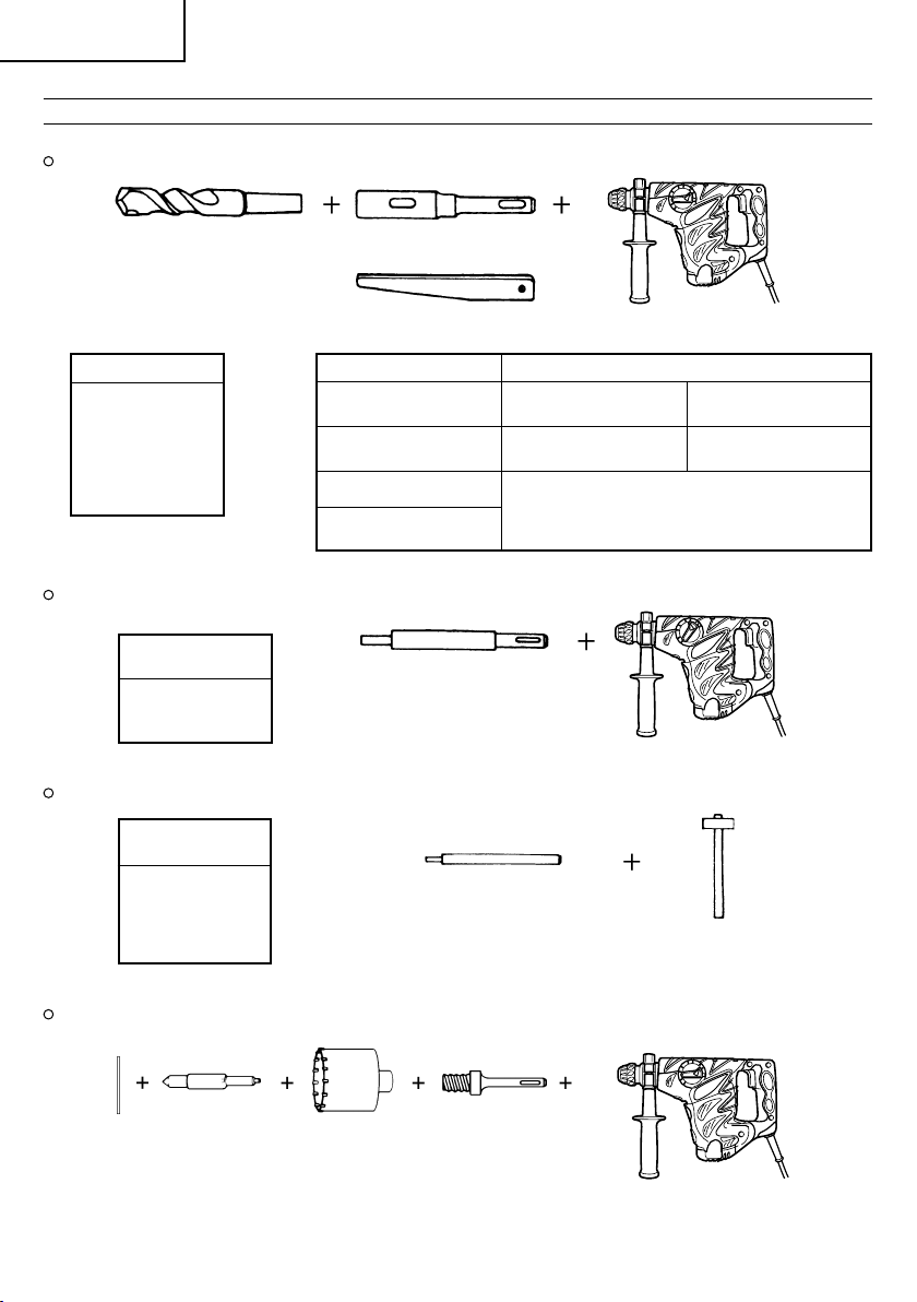
Français
ACCESSOIRES EN OPTION (vendus séparément)
1. Forage de trous pour fixations (rotation + percussion)
Foret de perçage (queue conique) et raccord de queue conique
Foret de perçage (queue conique)
Diamètre extérieur
11,0 mm
12,3 mm
12,7 mm
14,3 mm
14,5 mm
17,5 mm
21,5 mm
2. Mise en place de la fixation (percussion uniquement)
Raccord de mise en place de la fixation (pour marteau perforateur)
Dimension de
l’ancrage
W1/4"
W5/16"
W3/8"
Raccord de mise en place de la fixation (pour marteau)
Dimension de
l’ancrage
W1/4"
W5/16"
W3/8"
W1/2"
W5/8"
Raccord de queue conique
(Tige SDS plus)
Clavette
Tupe de cône Foret de perçage utilisé
Cône Morse (No.1)
Cône Morse (No.2)
Cône en A
Cône en B
Raccord de mise en place de la fixation
(Tige SDS plus)
(pour marteau perforateur)
Longueur totale: 160 mm, 260 mm
Raccord de mise en place de la
fixation
(pour marteau)
Foret de perçage utilisé
(queue conique)
Foret de perçage utilisé
(queue conique)
Le raccord de queue conique pour cône en
forme de A ou B est fourni en tant
qu’accessoire en option, mais le foret de
perçage qui lui correspond n’est pas fourni.
11,0 ~ 17,5 mm
21,5 mm
3. Perçage de trous de grand diamètre (rotation + percussion)
Goujon, couronne, queue de couronne et plaque de guidage.
Queue de couronne
(Tige SDS plus)
25
centrale de
guidage)
Goujon
Couronne(Plaque
Page 27
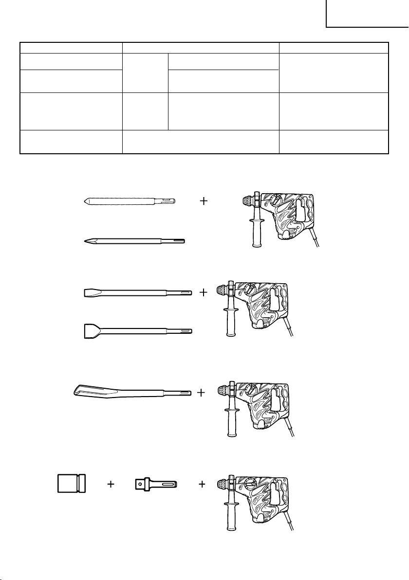
Goujon central Couronne (diamètre externe) Queue de couronne
–
Goujon central (A)
Goujon central (B) (B) 65 mm Queue de couronne (B)
Ne pas utiliser de couronne Avec la plaque de guidage (La plaque de
extérieure ayant un diamètre guidage n’est pas équipée pour des couronnes
extérieur de 25 mm de 29 mm. d’un diamètre extérieur de 25 mm et 29 mm.)
4. Opération de démolition (percussion uniquement)
Pointe de broyage (type rond) (Tige SDS plus)
Pointe de broyage (type carré) (Tige SDS-plus)
5. Rainurage et cassure des arêtes (percussion uniquement)
Ciseau à froid (Tige SDS plus)
(A)
25 mm
29 mm
32 mm Queue de couronne (A)
35 mm
38 mm
45 mm
50 mm
80 mm
90 mm
Français
Fraise (Tige SDS plus)
6. Rainurage (percussion uniquement)
Burin à rainer (Tige SDS plus)
7. Installation de boulon à ancrage chimique (rotation + percussion)
(Douille
standard sur
le marché)
Raccord d’ancre chimique 12,7 mm
Raccord d’ancre chimique 19 mm
(Tige SDS Plus)
26
Page 28

Français
8. Perçage de trous et insertion des vis (rotation seulement)
Mandrin porte-foret, raccord (G) de mandrin, vis spéciale et clé de mandrin
vis spéciale
9. Perçage de trous (rotation seulement)
Mandrin porte-foret
(13 VLD-D)
Ensemble du mandrin porte-foret de 13 mm (y compris la clé de mandrin) et mandrin (pour percer l’acier
ou le bois).
10. Vis d’entraînement (rotation seulement)
Mandrin porte-foret
(13 VLRB-D)
Clé de mandrin
Clé de mandrin
No. de mèche
Raccord (G) de mandrin
(Tige SDS plus)
Raccord (D) de mandrin
(Tige SDS-Plus)
Raccord (D) de mandrin
(Tige SDS plus)
No. de mèche dimension de vis Longueur
No.2 3 – 5 mm 25 mm
No.3 6 – 8 mm 25 mm
11. Graisse A pour marteau
500 g (en boîte)
70 g (en tube vert)
30 g (en tube vert)
Les accessoires standards sont sujets à changement sans préavis.
27
Page 29

Français
APPLICATIONS
Fonction de rotation et de percussion
Perçage de trous d’ancrage
Perçage de trous dans béton
Perçage de trous dans une tuile
Par action de rotation uniquement
Perçage de l’acier ou du bois
(avec accessoires en option)
Serreage de vis mécaniques et de vis à bois
(avec accessoires en option)
Fonction de percussion uniquement
Travaux légers de burinage de béton, de creusage
de rainure et de cassure des angles
AVANT LA MISE EN MARCHE
1. Source de puissance
S’assurer que la source de puissance à utiliser
correspond à la puissance indiquée sur la plaque
signalétique du produit.
2. Interrupteur de puissance
S’assurer que l’interrupteur de puissance est en
position ARRET. Si la fiche est branchée alors que
l’interrupteur est sur MARCHE, l’outil démarre
immédiatement et peut provoquer un grave accident.
3. Fil de rallonge
Lorsque la zone de travail est éloignée de la source
de puissance, utiliser un fil de rallonge d’une
épaisseur suffisante et d’une capacité nominale
suffisante. Le fil de rallonge doit être aussi court
que possible.
4. Montage du foret de perçage (Fig. 1)
ATTENTION
Afin d’éviter tout accident, s’assurer de mettre le
commutateur en position de coupure et de
débrancher la fiche de la prise.
NOTE
Lors de l’utilisation de pointes de broyage, forets,
etc., s’assurer de l’utilisation de pièces d’origines
conçues par notre société.
(1) Nettoyer la tige du foret.
(2) Pour fixer un foret de perçage (tige SDS plus), tirer
complètement l’attache coulissante dans le sens de
la flèche, comme indiqué sur la Fig. 1, puis insérer
le foret tout en le faisant tourner jusqu’à ce qu’il
atteigne le fond.
(3) Lorsque l’attache coulissante est relâchée, le foret
est fixé.
(4) Pour retirer le foret de perçage, tirer complètement
l’attache coulissante dans le sens de la flèche et
sortir le foret.
5. Installation du godet à poussière (accessoire en
option) (Fig. 2)
Lors de l’utilisation du marteau perforateur pour
effectuer des opérations de perçage vers le haut,
installer le godet à poussière pour une utilisation
aisée de l’outil.
Pose du capuchone à poussière
Utiliser la capuchone à poussière en la fixant au
foret comme montré dans la Fig. 2.
Lors de l’utilisation d’un foret avec un diamètre plus
grand, agrandir le trou central de la capuchon à
poussière avec ce Marteau perforateur.
ATTENTION:
Le godet à poussière est à utiliser exclusivement
lors du perçage de béton. Ne pas l’utiliser lors du
forage de bois ou de métal.
Vider les particules dans le collecteur à poussière
(B) chaque deux ou trois trous percés.
6. Sélection de la mèche pour visseuse
Les têtes de vis ou les mèches seront endommagées
si une mèche inappropriée au diamètre de la vis
n’est pas employée pour enfoncer la vis.
7. Sélection du mode de fonction
Le choix parmi les trois modes de travail “ percussion
uniquement ”, “ rotation+percussion ” et “ rotation
uniquement ” peut être effectué en tournant le
sélecteur tout en enfonçant le bouton-poussoir.
Amener le repère ▲ du sélecteur sur celui du mode
à utiliser.
ATTENTION:
Avant de régler le sélecteur, bien s’assurer que le
moteur est arrêté. L’outil risque de tomber en panne
si l’on règle le sélecteur pendant que le moteur
tourne.
Pour actionner le sélecteur, appuyer sur le bouton
poussoir et libérer le verrouillage du sélecteur. Par
ailleurs, après l’utilisation, bien s’assurer que le
bouton poussoir est revenu à sa position d’origine
et que le sélecteur est verrouillé.
Régler le sélecteur franchement. S’il est réglé à michemin entre deux positions de réglage, cela risque
de raccourcir la durée de service du mécanisme de
commutation.
UTILISATION
ATTENTION:
Pour éviter tout accident, vérifier que le commutateur
est en position de coupure et débrancher la fiche de la
prise pour installer et enlever les forets et les autres
pièces. Le commutateur devrait également être en
position de coupure pendant une pause ou après le
travail.
1. Fonctionnement de l’interrupteur
La vitesse de rotation du foret de perçage peut être
réglée suivant la force avec laquelle on appuie sur
l’interrupteur à détente. La vitesse est faible si on
exerce une légère pression et augmente si la
pression est plus forte.
2. Rotation + percussion
Ce marteau perforateur peut être mis en mode
rotation et percussion en tournant le sélecteur
jusqu’au repère
poussoir (Fig. 3). Tourner légèrement la poignée et
vérifier que le mode s’est enclenché d’un click.
(1) Monter le foret de perçage.
(2) Tirer l’interrupteur de déclenchement après avoir
appliqué la pointe du foret sur la position de perçage
désirée. (Fig. 4)
(3) Il n’est pas du tout nécessaire d’appliquer une forte
pression sur le perforateur. Il suffit d’appliquer une
légère pression de manière à ce que la poussière
et les éclats soient déchargés progressivement.
. tout en enfonçant le bouton-
28
Page 30

Français
ATTENTION:
Quand le foret de perçage touche une poutre en
fer, la mèche s’arrête immédiatement et la perceuse
réagit en tournant. Par conséquent, tenir fermement
la poignée principale et la poignée latérale, comme
indiqué à la Fig. 4.
3. Rotation seulement
Ce Marteau perforateur peut être mis sur le mode
de rotation uniquement en appuyant sur le boutonpoussoir et en tournant le sélecteur vers le repère
. (Fig. 5)
Tourner légèrement la poignée et vérifier que le
mode s’est enclenché d’un clic.
Pour percer du bois ou du métal en utilisant le
mandrin porte-foret et le raccord de mandrin
(accessoire en option), procéder de la manière
suivante.
Mise en place de mandrin porte-foret et du raccord
de mandrin. (Fig. 6)
(1) Attacher le mandrin porte foret au raccord de
mandrin.
(2) L’élément de la tige SDS est identique au foret de
perçage. Se reporter à “Montage du foret de
perçage” pour le fixer.
ATTENTION:
Si l’on applique une force excessive, cela donnera
un travail bâclé et abîmera la pointe du foret de
perçage, réduisant ainsi la durée de service de la
perceuse.
Les forets peuvent se casser lors du dégagement
du marteau perforateur hors du trou foré. Lors du
dégagement, il est important d’employer un
mouvement de poussée.
Ne pas essayer de percer des trous d’ancrage ou
des trous dans le béton quand la machine est réglée
sur rotation seulement.
Ne pas tenter d’utiliser le marteau perforateur en
mode de rotation et percussion lorsque le mandrin
porte foret et le raccord de mandrin sont installés.
4. Lors du vissage des vis machine (Fig. 7)
Tout d’abord, insérer la pièce dans la prise à
l’extrémité de l’adaptateur (D) de mandrin.
Ensuite, monter l’adaptateur (D) de mandrin sur
l’appareil principal en utilisant les procédures
décrites en 4 (1), (2), (3). Mettre la pointe de la pièce
dans les fentes de la tête de vis, maintenir l’appareil
principal et visser.
ATTENTION:
Faites attention de ne pas prolonger la durée
d’enfoncement plus qu’il n’est nécessaire, sinon les
vis pourraient être endommagées suite à la force
excessive utilisée.
Appliquez le Marteau perforateur
perpendiculairement par rapport à la tête de la vis
lors de l’enfoncement de la vis; sinon la tête de
la vis ou la mèche seront endommagées, ou la force
d’entraînement ne sera pas entièrement transférée
à la vis.
Ne pas tenter d’utiliser le marteau perforateur en
mode de rotation et percussion lorsque le raccord
de mandrin et la mèche sont installés.
5. Enfoncement de vis à bois (Fig. 7)
(1) Sélection d’une mèche appropriée
Utilisez des vis à tête cruciforme, autant que possible
étant donné que la mèche glisse souvent de la tête
des vis ordinaires.
(2) Enfoncement de vis à bois
Avant d’enfoncer des vis à bois, préparez d’abord
des trous appropriés aux vis utilisées dans le bois.
Appliquez la mèche aux fentes de la tête de la vis
et enfoncez la vis dans le bois en douceur.
Après avoir fait tourner le Marteau perforateur à
petite vitesse pendant un moment jusqu’à ce que
la vis à bois soit partiellement enfoncée, pressez
le trigger plus fortement afin d’obtenir la force
d’entraînement maximale.
ATTENTION:
Ne manquez pas de prendre en considération la
dureté du bois quand vous préparez un trou
approprié à recevoir la vis à bois. Si le trou est trop
petit ou pas assez profond, ce qui demande
beaucoup de force pour y enfoncer la vis, il se peut
que le filet de la vis de bois en soit endommagé.
6. Percussion uniquement
Ce marteau perforateur peut être mis en mode de
percussion uniquement en tournant le sélecteur
jusqu’au repère
poussoir (Fig. 8).
(1) Montez la pointe de broyage ou le burin.
(2) Enfoncer le bouton-poussoir et placer le sélecteur
sur le repère
La rotation est interrompue. Tournez la prise et
ajustez le burin sur la position souhaitée. (Fig. 10)
(3) Tourner le sélecteur sur le repère
La pointe de broyage ou le burin froid est verrouillé.
7. Utilisation de l’arràtoir (Fig. 11)
(1) Desserrer la poignée latérale, et insérer l’arretoir
dans le trou du boulon de poignée.
(2) Régler la position de l’arretoir en fonction de la
profondeur du trou et bien serrer la poignée latérale.
8. Comment utiliser la mèche (queue conique) et le
raccord de queue conique
(1) Monter le raccord de queue conique sur le Marteau
perforateur. (Fig. 12)
(2) Fixer la mèche (queue conique) sur le raccord de
queue conique. (Fig. 12)
(3) Mettre l’interrupteur sur la position de marche (ON)
et percer un trou de la profondeur voulue.
(4) Pour retirer la mèche (queue conique), introduire
la clavette dans la fente du raccord de queue conique
et frapper la tête de la clavette avec un marteau
alors que le perforateur est placé sur le support.
(Fig. 13)
9. Utilisation de la poignée latérale
Si l’on désire modifier la position de la poignée
latérale, tourner le manche de la poignée latérale
dans le sens inverse des aiguilles d’une montre
pour desserrer la poignée, puis la fixer solidement.
ATTENTION:
Lors du perçage d’un trou, il peut arriver que l’outil
se mette à tourner sous l’effet de la réaction au
moment de la pénétration d’un mur de béton et/
ou lorsque la pointe de la lame entre en contact
avec la barre béton. Fixer solidement la poignée
latérale et tenir l’outil des deux mains. Si l’outil
n’est pas tenu solidement, cela risque de provoquer
un accident.
. tout en enfonçant le bouton-
. (Fig. 9)
. (Fig. 8)
29
Page 31

Français
COMMENT UTILISER LA COURONNE
(POUR UNE CHARGE LEGERE)
Utiliser la couronne pour percer de grands trous.
L’utiliser avec le goujon central et la queue de couronne
fournis en tant qu’accessoires en option.
1. Montage
ATTENTION
S’assurer que l’interrupteur est sur la position d’arrêt
(OFF) et débrancher l’outil.
(1) Monter la couronne sur la queue de couronne. (Fig.
14)
Graisser le filetage da la queue de couronne afin
de faciliter le démontage.
(2) Monter la queue de couronne sur le Marteau
perforateur. (Fig. 15)
(3) Introduire le goujon central dans la plaque de
guidage jusqu’à ce qu’il arrête.
(4) Engager la plaque de guidage dans la couronne et
tourner la plaque de guidage à gauche ou à droite
de manière qu’elle ne puisse pas tomber, même
si elle orientée vers le bas. (Fig. 16)
2. Perçage (Fig. 17)
(1) Brancher le perforateur dans la source
d'alimentation.
(2) Le goujon central est muni d’un ressort.
Le pousser légèrement et perpendiculairement contre
le mur ou le plancher. Toute la surface de la
couronne doit être en contact avec le mur ou le
plancher. Mettre en marche.
(3) Quand on a percé sur une profondeur d’environ 5
mm, la position du trou est déterminée. Continuer
à percer après avoir retiré le goujon central et la
plaque de guidage de la couronne.
(4) Si l’on applique une force excessive, cela donnera
un travail bâclé et abîmera la pointe du foret de
perçage, réduisant ainsi la durée de service de la
perceuse à percussion.
ATTENTION
Quand on retire le goujon central et la plaque de
guidage, mettre l’interrupteur sur la position d’arrêt
(OFF) et débrancher la perceuse.
3. Démontage (Fig. 18)
Une autre méthode consiste à retirer la queue de
la couronne du Marteau perforateur et à frapper
fortement la tête de la queue de la couronne deux
ou trois fois avec un marteau, tout en maintenant
la couronne. Cela aura pour effet de desserrer le
filetage et on pourra retirer la couronne.
REMPLACEMENT DE GRAISSE
Cette machine est entièrement étanche afin d’éviter toute
pénétration de poussière et toute fuite de lubrifiant. Cet
outil peut être utilisé sans remplissage de graisse pendant
une longue période de temps. Cependant, remplacer la
graisse pour ne pas écourter la durée de vie. Remplacer
la graisse comme indiqué ci-dessous.
1. Période de remplacement
Contrôler la quantité de graisse lors du
remplacement de la brosse de carbone. (Voir
l'élément 4 de la section MAINTENANCE ET
INSPECTION.)
Se procurer la graisse chez l’Agence de Service
Autorisée Hitachi la plus proche.
Si vous devez changer la graisse vous-même, veuillez
respecter les points suivants.
2. Comment remplacer la graisse
ATTENTION:
Avant de remplacer la graisse, fermer l’interrupteur
et débrancher l’outil de la prise de courant.
(1) Démonter le couvercle de manivelle et essuyer
complètement la vieille graisse à l’intérieur. (Fig. 19)
(2) Mettre 30g de graisse A Hitachi pour marteau
électrique (accessoire de série, en tube) dans le
carter.
(3) Après avoir remplacé la graisse, remonter fermement
le carter. A ce moment, ne pas endommager ni
desserrer le joint d’huile.
NOTA:
La graisse pour Marteau électrique Hitachi A est du
type à viscosité faible; quand le tube est vide,
adressez-vous à votre Agent de Service Autorisé
Hitachi pour vous en procurer un nouveau.
ENTRETIEN ET VERIFICATION
1. Contrôle du foret de perçage
Etant donné que l’utilisation d’une mèche usée
entraînera un mauvais fonctionnement du moteur
et une diminution de l’efficacité, remplacez la mèche
usée par une neuve ou aiguisez-la immédiatement
et dès que vous notez une certaine usure.
2. Contrôle des vis de montage:
Vérifier régulièrement les vis de montage et s’assurer
qu’elles sont correctement serrées. Resserrer
immédiatement toute vis desserrée. Sinon, il y a
danger sérieux.
3. Entretien du moteur
Le bobinage de l’ensemble moteur est le “coeur”
même de l’outil électro-portatif. Veiller
soigneusement à ce que ce bobinage ne soit pas
endommagé et/ou mouillé par de l’huile ou de
l’eau.
4. Inspection des balais en carbone
Pour assurer à tout moment la sécurité et la
protection contre les chocs électrique, confier
l’inspection et le remplacement des balais en carbone
de l’outil EXCLUSIVEMENT à un centre de service
après-vente agréé par HITACHI.
5. Remplacer le câble d’alimentation
Si le câble d’alimentation de l’outil est endommagé,
l’outil doit être renvoyé à un centre d’entretien
Hitachi agréé pour remplacement du câble.
6. Liste des pièces de rechange
A: No. élément
B: No. code
C: No. utilisé
D: Remarques
30
Page 32

Français
ATTENTION
Les réparations, modifications et inspections des
outils électriques Hitachi doivent être confiées à un
service après-vente Hitachi agréé.
Il sera utile de présenter cette liste de pièces au
service après-vente Hitachi agréé lorsqu’on apporte
un outil nécessitant des réparations ou tout autre
entretien.
Lors de l’utilisation et de l’entretien d’un outil
électrique, respecter les règlements et les normes
de sécurité en vigueur dans le pays en question.
MODIFICATIONS
Les outils électriques Hitachi sont constamment
améliorés et modifiés afin d’incorporer les tous
derniers progrès technologiques.
En conséquence, il est possible que certaines pièces
(c.-à-d. no. de code et/ou dessin) soient modifiées
sans avis préalable.
GARANTIE
Nous garantissons que les outils électriques Hitachi sont
conformes aux réglementations légales/locales
spécifiques. Cette garantie ne couvre pas les pannes ou
dommages dus à un usage impropre, inapproprié ou à
une usure normale. Pour toute réclamation, veuillez
envoyer l’outil électrique, non démonté, avec le
CERTIFICAT DE GARANTIE que vous trouverez à la fin de
ce manuel d’utilisation, à un centre de service aprèsvente agréé Hitachi.
Au sujet du bruit et des vibrations
Les valeurs mesurées ont été déterminées en fonction
de la norme EN60745 et déclarées conforme à ISO 4871.
Niveau de puissance sonore pondérée A: 100 dB (A)
Niveau de pression acoustique pondérée A: 89 dB (A)
Incertitude KpA: 3 dB (A)
Porter un casque de protection.
Valeurs totales des vibration (somme vectorielle triaxiale)
déterminée conformément à EN60745.
Forage du béton:
Valeur d’émission de vibration
Incertitude K = 1,9 m/s2 (A)
Ciselage:
Valeur d’émission de vibration
Incertitude K = 6,5 m/s2 (A)
Charge à vide :
Valeur d’émission de vibration
Incertitude K = 3,0 m/s2 (A)
Valeur de sous-solage équivalente:
Valeur d’émission de vibration
Incertitude K = 6,5 m/s2 (A)
ah, HD = 19,8 m/s
ah, CH = 13,6 m/s
ah, NL = 4,2 m/s
ah, CHeq = 12,3 m/s
2
2
2
2
NOTA:
Par suite du programme permanent de recherche et de
développement HITACHI, ces spécifications peuvent faire
l’objet de modifications sans avis préalable.
31
AVERTISSEMENT
䡬 La valeur d’émission de vibration en fonctionnement
de l’outil électrique peut être différente de la valeur
déclarée, en fonction des utilisations de l’outil.
䡬 Pour identifier les mesures de protection de
l’utilisateur fondées sur une estimation de
l’exposition en conditions d’uitilisation (tenant
compte de tous les aspects du cycle d’utilisation,
tels que les moments où l’outil est mis hors tension
ou lorsqu’il tourne à vide en plus des temps de
déclenchements)
Page 33

Italiano
AVVERTIMENTI GENERALI DI SICUREZZA
SUGLI UTENSILI ELETTRICI
AVVERTENZA
Leggere tutti gli avvertimenti di sicurezza e tutte le
istruzioni.
La mancata osservanza degli avvertimenti e delle istruzioni
potrebbe essere causa di scosse elettriche, incendi e/o
gravi lesioni.
Salvare tutti gli avvertimenti e le istruzioni per riferimenti
futuri.
Il termine “elettroutensili” riportato nelle avvertenze si
riferisce agli elettroutensili azionati con alimentazione di
rete (via cavi) o a batterie (senza cavi).
1) Sicurezza dell’area operativa
a) Mantenere l'area operativa pulita e ordinata.
Aree operative sporche o disordinate possono
favorire gli infortuni.
b) Non utilizzare gli elettroutensili in atmosfere
esplosive, ad es. in presenza di liquidi , gas o
polveri infiammabili.
Gli elettroutensili generano delle scintille che
potrebbero accendere la polvere o i fumi.
c) Tenere lontani bambini e astanti durante l'utilizzo
degli elettroutensili.
Qualsiasi distrazione può essere causa di perdita
di controllo.
2) Sicurezza elettrica
a) Le spine degli elettroutensili devono essere idonee
alle prese disponibili.
Non modificare mai le prese.
Con gli elettroutensili a massa (messi a terra),
non utilizzare alcun adattatore.
L'utilizzo di spine intatte e corrispondenti alle prese
disponibili ridurrà il rischio di scosse elettriche.
b) Evitare qualsiasi contatto con le superfici a massa
o a terra, quali tubi, radiatori, fornelli e frigoriferi.
In caso di messa a terra o massa del corpo, sussiste
un maggior rischio di scosse elettriche.
c) Non esporre gli elettroutensili alla pioggia o
all'umidità.
La penetrazione di acqua negli elettroutensili
aumenterà il rischio di scosse elettriche.
d) Non tirare il cavo. Non utilizzarlo per il trasporto,
o per tirare o scollegare l'elettroutensile.
Tenere il cavo lontano da fonti di calore, oli, bordi
appuntiti o parti in movimento.
Cavi danneggiati o attorcigliati possono
aumentare il rischio di scosse elettriche.
e) Durante l'uso degli elettroutensili all'esterno,
utilizzare una prolunga idonea per usi esterni.
L'utilizzo di cavi per esterno riduce il rischio di
scosse elettriche.
f) Se è impossibile evitare l’impiego di un utensile
elettrico in un luogo umido, utilizzare
l’alimentazione protetta da un dispositivo a
corrente residua (RCD).
L’uso di un RCD riduce il rischio di scosse elettriche.
3) Sicurezza personale
a) Durante l'uso degli elettroutensili, state all'erta,
verificate ciò che state eseguendo e adottate
sempre il buon senso.
Non utilizzate gli elettroutensili qualora siate stanchi,
sotto l'influenza di farmaci, alcol o cure mediche.
Anche un attimo di disattenzione durante l'uso
degli elettroutensili potrebbe essere causa di gravi
lesioni personali.
b) Indossate l'attrezzatura di protezione personale.
Indossate sempre le protezioni oculari.
L'attrezzatura protettiva, quali maschera facciale,
calzature antiscivolo, caschi o protezioni oculari
ridurrà il rischio di lesioni personali.
c) Impedite le accensioni involontarie. Prima del
collegamento a una sorgente di alimentazione e/
o pacco batteria e prima di raccogliere o
trasportare l’utensile, verificate che l'interruttore
sia posizionato su OFF.
Il trasporto degli elettroutensili tenendo le dita
sull'interruttore o l’attivazione elettrica degli
utensile che hanno l’interruttore su ON, implica il
rischio di incidenti.
d) Prima di attivare l'elettroutensile, rimuovete
qualsiasi chiave di regolazione.
Lasciando la chiave in un componente in rotazione
dell'elettroutensile, sussiste il rischio di lesioni
personali.
e) Mantenersi in equilibrio. Mantenersi sempre su
due piedi, in equilibrio stabile.
Ciò consente di controllare al meglio
l'elettroutensile in caso di situazioni impreviste.
f) Vestirsi in modo adeguato. Non indossare abiti
larghi o gioielli. Tenere i capelli, gli abiti e i guanti
lontano dalle parti in movimento.
Abiti allentati, gioielli e capelli lunghi potrebbero
impigliarsi nelle parti in movimento.
g) In caso di dispositivi provvisti di collegamento ad
apparecchiature di rimozione e raccolta polveri,
verificare che queste siano collegate e utilizzate
in modo adeguato.
L'utilizzo della raccolta della polvere può ridurre i
rischi connessi alle polveri.
4) Utilizzo e manutenzione degli elettroutensili
a) Non utilizzare elettroutensili non idonei. Utilizzare
l'elettroutensile idoneo alla propria applicazione.
Utilizzando l'elettroutensile corretto, si garantirà
un'esecuzione migliore e più sicura del lavoro,
alla velocità di progetto.
b) Non utilizzare l'elettroutensile qualora non sia
possibile accenderlo/spegnerlo tramite
l'interruttore.
É pericoloso utilizzare elettroutensili che non
possano essere azionati dall'interruttore.
Provvedere alla relativa riparazione.
c) Prima di effettuare qualsiasi regolazione, sostituire
gli accessori o depositare gli elettroutensili,
scollegare la spina dalla presa elettrica e/o il pacco
batteria dall’utensile elettrico.
Queste misure di sicurezza preventive riducono il
rischio di avvio involontario dell'elettroutensile.
d) Depositare gli elettroutensili non utilizzati lontano
dalla portata dei bambini ed evitare che persone
non esperte di elettroutensili o non a conoscenza
di quanto riportato sulle presenti istruzioni
azionino l'elettroutensile.
É pericoloso consentire che utenti non esperti
utilizzino gli elettroutensili.
32
Page 34

Italiano
e) Manutenzione degli elettroutensili. Verificare che
non vi siano componenti in movimento disallineati
o bloccati, componenti rotti o altre condizioni
che potrebbero influenzare negativamente il
funzionamento dell'elettroutensile.
In caso di guasti, provvedere alla riparazione
dell'elettroutensile prima di riutilizzarlo.
Molti incidenti sono causati da una scarsa
manutenzione.
f) Mantenere gli strumenti di taglio affilati e puliti.
Gli strumenti di taglio in condizioni di
manutenzione adeguata, con bordi affilati, sono
meno soggetti al bloccaggio e sono più facilmente
controllabili.
g) Utilizzare l'elettroutensile, gli accessori, le barrette,
ecc. in conformità a quanto riportato nelle presenti
istruzioni, tenendo in debita considerazione le
condizioni operative e il tipo di lavoro da eseguire.
L’uso dell’utensile elettrico per operazioni diverse
da quelle previste potrebbe causare una situazione
pericolosa.
5) Assistenza
a) Affidate le riparazioni dell'elettroutensile a
persone qualificate che utilizzino solamente parti
di ricambio identiche.
Ciò garantirà il mantenimento della sicurezza
dell'elettroutensile.
PRECAUZIONI
Tenere lontano dalla portata di bambini e invalidi.
Quando non utilizzati, gli strumenti dovranno essere
deposti lontano dalla portata di bambini e invalidi.
CARATTERISTICHE
PRECAUZIONI PER L’USO DEL MARTELLO
ROTANTE
1. Indossare dispositivi di protezione per l’udito.
L’esposizione al rumore può causare la perdita
dell’udito.
2. Usare le impugnature ausiliarie fornite in dotazione
con l’attrezzo.
La perdita di controllo può causare lesioni personali.
3. Non toccate la punta dell’attrezzo durante il
funzionamento o subito dopo. Durante il
funzionamento la punta diventa bollente e può
causare gravi ustioni.
4. Prima di iniziare a frantumare, scheggiare o forare
una parete, un pavimento o un soffitto, verificare
accuratamente che non vi siano cavi o condotti
elettrici nascosti all’interno di questi.
5. Tenete sempre saldamente l’impugnatura del corpo
dell’attrezzo e l’impugnatura laterale dello stesso.
In caso contrario, la forza contraria prodotta potrebbe
dare luogo ad un funzionamento impreciso e
addirittura pericoloso.
6. Indossate una mascherina filtrante
Non inalate la polvere nociva generata durante le
operazioni di trapanatura o demolizione. La polvere
può nuocere alla salute vostra e delle persone
presenti.
Voltaggio (per zona)* (110 V, 115 V, 120 V, 127 V, 220 V, 230 V, 240 V)
Potenza assorbita 850 W*
Velocità senza carico 0 – 850 min
Frequenza d’impatto a pieno carico 0 – 3700 min
Capacità: cemento 4 – 30 mm
Peso (escluso il cavo e l’impugnatura laterale) 4,3 kg
* Accertatevi di aver controllato bene la piastrina perché essa varia da zona a zona.
acciaio 13 mm
legno 32 mm
–1
–1
ACCESSORI STANDARD
(1) Valigetta di plastica .................................................. 1
(2) Impugnatura laterale ................................................. 1
(3) Fermo .......................................................................... 1
(4) Contenitore a polvere .............................................. 1
(5) Siringa ......................................................................... 1
33
Gli accessori standard possono essere modificati senza
preavviso.
Page 35

ACCESSORI DISPONIBILI A RICHIESTA (venduti separatamente)
1. Esecuzione di fori per tasselli di ancoraggio (rotazione + martello)
Punta (a gambo conico) e adattatore per gambo conico.
Italiano
Broca de taladro (vástago cónico) Adaptador cónico
Diametro esterno
11,0 mm
12,3 mm
12,7 mm
14,3 mm
14,5 mm
17,5 mm
21,5 mm
2. Fissaggio di ancoraggio (solo martello)
Adattatore per ancoraggio (per trapano a percussione)
Adattatore per ancoraggio (Asta SDS Plus)
(per trapano a percussione)
Lunghezza totale: 160 mm, 260 mm
Dimensioni
dell’ancora
W1/4"
W5/16"
W3/8"
Adattatore per ancoraggio (per inserimento con martello manuale)
(Asta SDS Plus)
Coppiglia
Tipo di conicità Punta usabile
Conicità Morse (n.1)
Conicità Morse (n.2)
Conicità A L’adattatore per gambo a conicità A o B è
Conicità B la punta per tale gambo.
Punta (a gambo conico)
Punta (a gambo conico)
disponibili a richiesta. Non è per contro disponibile
11,0 ~ 17,5 mm
21,5 mm
Dimensioni
dell’ancora
W1/4"
W5/16"
W3/8"
W1/2"
W5/8"
Adattatore per ancoraggio
(per inserimento con martello
manuale)
34
Page 36

Italiano
3. Esecuzione di fori di grosso diametro (rotazione + martello)
Punta della corona, corona, gambo della corona e piastra guida.
(Piastra
guida)
Punta della corona Corona (diametro esterno) Gambo della corona
Punta della corona (A) 35 mm
Punta della corona (B) (B) 65 mm Gambo della corona (B)
Non usare corone con Con piastra guida (La piastra guida non è
diametro di 25 mm o 29 mm. dotata di corona di 25 mm o 29 mm diametro.)
4. Demolizione (solo martello)
Punta gigante (Tipo rotondo) (Asta SDS Plus)
Punta gigante (Tpo quadrato) (gambo SDS-più)
5. Esecuzione di scanalature e bordi (solo martello)
Tagliolo a freddo (Asta SDS plus)
Punta della
corona
–
Corona Gambo della corona
(A)
(Asta SDS Plus)
25 mm
29 mm
32 mm Gambo della corona (A)
38 mm
45 mm
50 mm
80 mm
90 mm
Coltello (Asta SDS plus)
6. Esecuzione di scanalature profonde (solo martello)
Scalpello per scanalare (Asta SDS plus)
35
Page 37

7. Installazione di tasselli con ancoraggio chimico (rotazione + martello)
Italiano
(Prese sul mercato)
8. Foratura e viti di guide (solo rotazione)
Mandrino, adattatore (G) per mandrino, vite speciale chiave per mandrino
Vite speciale
9. Foratura (solo rotazione)
Mandrino (13 VLD-D)
Chiave per mandrino
Mandrino (13 VLRB-D)
Chiave per mandrino
(Asta SDS Plus)
Adattatore dell’ancoraggio
chimico 12,7 mm
Adattatore dell’ancoraggio
chimico 19 mm
Adattatore (G) per mandrino
(Asta SDS Plus)
Adattatore (D) per
mandrino
(Asta SDS plus)
䡬 Gruppo mandrino di 13 mm (con chiave) e mandrino (per foratura nell’acciaio e nel legno).
10. Viti d guida (solo relazione)
Punta in.
Adattatore (D) per mandrino
(Asta SDS Plus)
Punta in. Dimensioni vite Lunghezza
No.2 3 - 5 mm 25 mm
No.3 6 - 8 mm 25 mm
36
Page 38

Italiano
11. Grasso A per martello
500 g (in lattina)
70 g (nel tubo arancione)
30 g (nel tubo arancione)
Gli accessori disponibili a richiesta sono soggetti a modifiche senza preavviso.
APPLICAZIONI
Rotazione e funzione martello
Apertura di fori da ancoraggio
Apertura di fori nel cemento armato
Apertura di fori in tegole
Con sola rotazione
Foratura di acciaio o legno
(con accessori disponibili a richiesta)
Viti di fissaggio per macchine, viti del legno.
(con accessori disponibili a richiesta)
Solo funzione martello
Scalpellatura leggera di cemento, scavatura o
bordatura di scanalature
PRIMA DI INIZIARE LE OPERAZIONI
1. Alimentazione
Assicurarsi che la rete di alimentazione che si vuole
usare sia compatibile con le caratteristiche relative
all’alimentazione di corrente specificate nella
piastrina dell’apparecchio.
2. Interruttore di corrente
Mettere l’interruttore in posizione SPENTO. Se la
spina è infilata in una presa mentre l’interruttore
è acceso, l’utensile elettrico si mette immediatamente
in moto, facilitando il verificarsi di incidenti gravi.
3. Prolunga del cavo
Quando l’ambiente di lavoro è lontano da una presa
di corrente, usare una prolunga del cavo di sufficiente
spessore e di prestazione adeguata. La prolunga
deve essere più corta possibile.
4. Montaggio della punta (Fig. 1)
ATTENZIONE
Per evitare incidenti, assicuratevi di spegnere
l’interruttore e scollegare la spina dalla presa.
NOTA
Per utilizzare utensili quali punte da scavo a centrare,
punte da trapano, ecc., ricordate di impiegare sempre
le parti originali designate dalla nostra azienda.
(1) Pulite la porzione del codolo della punta da trapano.
(2) Per applicare una punta del trapano (Asta SDS
plus), tirare completamente il mandrino in direzione
della freccia come mostrato nella Fig. 1 e inserire
la punta del trapano fino in fondo ruotandola.
(3) La punta del trapano è assicurata in posizione
rilasciando il mandrino.
(4) Per staccare la punta del trapano, tirare
completamente il mandrino in direzione della freccia
e tirare in fuori la punta del trapano.
5. Installazione della coppa di raccolta della polvere
(accessori opzionali) (Fig. 2)
Se dovete utilizzare un martello rotante per trapanare
con un movimento dal basso verso l’alto, fissate
l’apposita coppa per raccogliere la polvere o i detriti
e facilitare l’intervento.
Installazione del contenitore a polvere
Usare il contenitore a polvere attaccandolo alla
punta del martello perforatore come mostrato nella
Fig. 2.
Quando si usa una punta con ampio diametro,
allagare il foro centrale del contenitore a polvere
con questo martello perforatore.
ATTENZIONE:
La coppa di raccolta della polvere serve
esclusivamente per i lavori di foratura del cemento.
Non usarla per forare legno o metallo.
Particelle di scarica nel camera a polvere (B) ogni
due o tre perforazioni.
6. Scelta della punta
Se si usa une punta non appropriata per il diametro
della vite, si rischis di danneggiare la testa della
vita stessa o la punta.
7. Selezione del modo di funzionamento
Ruotando la leva di selezione mentre si tiene
premuto il pulsante, è possibile passare
alternativamente dall’uno all’altro dei 3 modi di
funzionamento: “solo martello”, “rotazione +
martello” e “solo rotazione”. Regolare la posizione
▲ del segno della leva di cambiamento sul modo
che si vuole utilizzare.
ATTENZIONE:
Prima di agire sulla leva di cambiamento, controllare
che il motore si sia fermato.
Si può verificare un guasto se viene usata mentre
il motore è in funzione.
Per azionare la leva di cambiamento, premere il
tasto a pressione e sbloccare la leva di cambiamento.
Inoltre controllare dopo l’operazione che il tasto a
pressione sia tornato indietro e che la leva di
cambiamento sia bloccata.
Spostare la leva di cambiamento senza fare errori.
Se viene usata in una posizione intermedia, esiste
il rischio che la durata utile del meccanismo di
commutazione sia abbreviata.
OPERAZIONE
ATTENZIONE:
Per evitare possibili incidenti, ricordate di spegnere
l’interruttore e scollegare la spina dalla presa al momento
di installare o rimuovere le punte da trapano e i vari altri
componenti. Inoltre, l’interruttore dell’alimentazione deve
essere spento durante le pause e una volta terminato il
turno di lavoro.
1. Funzionaménto dell’interruttore
Si può regolare la velocità di rotazione del trapano
variando la corsa del grilletto-interruttore. La velocita
è bassa quando l’interruttore a grilletto è premuto
leggermente e aumenta quando si preme di più sul
(grilletto) grilletto.
2. Rotazione + martello
Su questo martello rotante, premendo il pulsante
e girando la leva di selezione sul segno
(Fig. 3) si può impostare il modo rotazione e martello.
Ruotare leggermente la manopola e assicurarsi che
la frizione si sia innestata con un clic.
37
Page 39

Italiano
(1) Montare la punta.
(2) Premere l’interruttore a grilletto dopo aver applicato
la punta sul luogo da forare. (Fig. 4)
(3) Non è assolutamente necessario eserciatare una
grande forza sul trapano. Spingere invece il trapano
solo leggermente, in modo che si veda la polvere
uscire dal foro.
ATTENZIONE:
Se la punta, durante la penetrazione nel materiale,
dovesse incontrare del ferro, essa portrebbe avere
la tendenza a fermarsi (non può girare), il che
causerebbe a sua volta la tendenza del trapano a
girare in senso opposto. Per tale ragione è
consigliabile afferrare sempre saldamente sia
l’impugnatura principale che laterale, come mostrato
in Fig. 4.
3. Sola rotazione
Per inserire il modo di funzionamento a sola
rotazione, far girare il selettore premere il tasto a
pressionee per portarlo in posizione
Ruotate leggermente la manopola e assicuratevi
che la frizione si sia innestata con un clic.
Per eseguire dei fori nel legno o nel metallo facendo
uso del mandrino e dell’adattatore per mandrino
(accessorio disponibile a richiesta), procedere nel
modo seguente.
Montaggio del mandrino e dell’adattatore per
mandrino: (Fig. 6)
(1) Montare il mandrino portapunta sul relativo
adattatore.
(2) La parte dell’asta SDS plus è uguale alla punta del
trapano. Perciò per applicarla fare riferimento alla
sezione “Montaggio della punta”.
ATTENZIONE:
Applicando una forza più elevata di quanto non sia
necessario non si accelera per niente l’esecuzione
del lavoro. Si rischia invece di deteriorare la punta
e di ridurre la durabilità del trapano.
Le punte da trapano potrebbero saltare via dal
mandrino quando si tenta di estrarre il martello
rotante dal foro appena eseguito. Per togliere
l’attrezzo, è importante usare un movimento di spinta.
Non tentare di eseguire dei fori di ancoraggio o dei
fori nel cemento usando la sola funzione di
rotazione!.
Non cercare di usare il martello rotante con la
funzione rotazione e martello se il mandrino
portapunta e il relativo adattatore sono installati.
4. Quando si infilano le viti di macchina (Fig. 7)
Innanzitutto inserire la punta del trapano nella
fessura in fondo all’adattore (D) del mandrino.
Poi montare l’adattore (D) del mandrino sull’unità
principale usando il procedimento descritto in 4 (1),
(2), (3), inserire la punta del trapano nelle fessure
sulla testa della vite, afferrare l’unità principale e
stringere la vite.
ATTENZIONE:
Attenzione a non prolungare eccessivamente la
durata dell’avvitamento, altrimenti la vite può venire
danneggiata a causa della forza eccessiva.
Per avvitare un perforatore, disporre l’utensile
perpendicolare alla testa della vite, altrimenti è
possibile che la testa della vite o la punta del
giravite si rovinino, oppure che la forza di
avvitamento non venga trasferita completamente
alla vite.
Non cercare di usare il martello rotante con la
funzione rotazione e martello se l’adattatore del
mandrino e la punta sono installati.
(Fig. 5).
5. Avvitamento di viti del legno (Fig. 7)
(1) Scelta dalla punta
Se possibile, usare una vite con testa a croce.
Usando una vite con testa a meno, la punta potrebbe
scivolare fuori facilmente.
(2) Avvitamento di viti del legno
Prima di avvitare viti del legno, eseguire un foro
quida nel materiale da avvitare. Disporre la punta
sulla acanalatura della testa della vite e avvitare con
cura.
Far girare prima il giravite a bassa velocità per un
momento, fino a quando la perforatrice è
parzialmente, inserita nel legno; dopo di che,
premere più fortemente il grilletto, fino ad ottenere
la velocità di avvitamento ideale.
ATTENZIONE:
Preparare il foro guida con cura, tenendo in
considerazione la durezza del legno. Se il foro
dovesse essere troppo piccolo o profondo, sarebbe
necessario applicare una forza di avvitamento tale,
che il passo della vite del legno potrebbe venire
rovinato.
6. Solo martello
Su questo martello rotante, premendo il pulsante
e girando la leva di selezione sul segno
si può impostare il modo martello soltanto.
(1) Montare la punta grande o lo scalpello.
(2) Premete il pulsante e posizionate la leva di selezione
sul segno
Quando la rotazione viene rilasciata, girare
l’impugnatura e regolare lo scalpello sulla posizione
desiderata. (Fig. 10)
(3) Girare il selettore sul segno
Poi la punta gigante o lo scalpello a freddo sono
bloccati.
7. Uso del fermo (Fig.11)
(1) Allentare il manico laterale e inserire il fermo nel
foro del bullone manico.
(2) Regolare la posizione del fermo a seconda della
profondità del foro e fissare bene il manico laterale.
8. Uso della punta a gambo conico insieme con
l’adattatore per gambo conico
(1) Montare l’adattatore per gambo conico sul trapano
(Fig. 12)
(2) Montare la punta a gambo conico sull’adattatore
per punta a gambo conico (Fig. 12)
(3) Accendere l’attrezzo ed eseguire il foro secondo la
profondità prestabilita.
(4) Per smontare la punta a gambo conico inserire la
coppiglia nella fessura dell’adattatore per gambo
conico e battere sulla punta (della coppiglia) con
un martello, con l’attrezzo e la punta appoggiati su
dei supporti (Fig. 13)
9. Uso dell’impugnatura laterale
Quando si desidera cambiare la posizione
dell’impugnatura laterale, girare la presa
dell’impugnatura laterale in senso antiorario per
allentarla e quindi fissarla saldamente.
ATTENZIONE:
Quando si trapana un foro, esistono casi in cui la
macchina tenta di ruotare per reazione quando si
trapanano pareti in cemento e/o quando la punta
viene in contatto con la barra.
Fissare saldamente l’impugnatura laterale e tenere
la macchina con entrambe le mani. Se non la si
tiene saldamente, possono verificarsi incidenti.
. (Fig. 9)
. (Fig. 8)
(Fig. 8)
38
Page 40

Italiano
USO DELLA CORONA (PER CARICHI
LIMITATI)
Per eseguire dei fori ad ampio raggio usare una corona
(carico limitato). La corona va usata in combinazione
con la punta della corona ed il gambo della corona, pure
disponibili quali accessori opzionali.
1. Montaggio
ATTENZIONE
Controllare che l’attrezzo sia spento e non collegato
alla presa di rete.
(1) Montare la corona sul gambo della corona (Fig. 14).
Lubrificare la filettatura del gambo della corona, in
modo da facilitare lo smontaggio.
(2) Montare il gambo della corona sul trapano (Fig. 15).
(3) Inserire la punta della corona nella piastra guida,
a fondo.
(4) Innestare la piastra guida e la corona e girare la
piastra guida verso destra o sinistra, in modo che
non si piega anche girandola verso il basso (Fig. 16).
2. Esecuzione di forature (Fig. 17)
(1) Inserire la spina del cavo in una presa di rete.
(2) Nel perno centrale è installata una molla.
Spingerlo leggermente contro la parete o il
pavimento, con un movimento rettilineo. Fare in
modo che le due superfici siano bene in contatto
e mettere l’attrezzo in funzione.
(3) Dopo aver forato fino ad una profondità di circa
5 mm, la posizione del foro diventa stabile. A questo
momento continuare la foratura senza punta della
corona e la piastra guida.
(4) Esercitando unaforza eccessiva sul trapano, durante
la foratura, non si aumenta la velocità di esecuzione
del lavoro, ma si causa soltanto il più veloce
consumo della punta e la diminuzione della durata
del trapano.
ATTENZIONE
Prima di togliere la punta della corona e la piastra
guida spegnere l’apparecchio e levare la spina dalla
presa di rete.
3. Smontaggio (Fig. 18)
È possibile procedere con un altro metodo: togliere
il gambo della corona dal trapano e battere
fortemente con un martello due o tre volte la testa
del gambo della corona. Si allenta cosi la filettatura
e la corona può essere smontata.
SOSTITUZIONE DEL GRASSO
Questo attrezzo ha una struttura completamente ermetica
all’aria, per proteggerla dall’ingresso della polvere e dalle
perdite di lubrificante. Questo apparecchio può essere
usato senza rifornire il grasso per un lungo periodo di
tempo. Tuttavia, effettuare la sostituzione del grasso per
prolungare la durata di servizio. Sostituire il grasso come
specificato di seguito.
1. Periodo di sostituzione del grasso.
Controllare il grasso quando si cambia la spazzola
di carbone. (Vedere la voce 4 nella sezione
MANUTENZIONE E CONTROLLO.)
L’operazione deve essere eseguita dal più vicino
Agente di Servizio autorizzato Hitachi.
In caso si debba sostituire il grasso personalmente,
procedere secondo i seguenti punti.
2. Come sostituire il grasso
ATTENZIONE:
Prima della sostituzione spegnere l’interruttore e
staccare la spina dalla presa di corrente.
(1) Smontare il coperchio dell’incastellatura e strofinare
via completamente il grasso vecchio che si trova
all’interno. (Fig. 19).
(2) Applicare 30g di grasso per martelli elettrici Hitachi
Electric Hammer Grease A (accessorio standard,
fornito in tubetto) nel basamento.
(3) A sostituzione del grasso avvenuta rimontare
l’alloggio dell’incastellatura. A questo punto fare
attenzione a non danneggiare o perdere il sigillo
paraolio.
NOTA:
Il Grasso per Martelli Elettrici Hitachi A è del tipo
a bassa viscosità. Quando il grasso viene finito,
acquistatene un altro da un Agente di Servizio
Autorizzato Hitachi.
MANUTENZIONE ED ISPEZIONE
1. Controllo della punta
L’uso di punte usurate causa un malfunzionamento
del motore e un abbassamento dell’efficenza di
lavoro. Sostituire le punte usurate o appuntirle
immediatamente quando si notano segni di
abrasione.
2. Controllo delle viti di tenuta
Controllare regolarmente tutte le viti di tenuta e
assicurarsi che siano esclusìvamente serrate. Nel
caso che una di queste viti dovesse allentarsi
riserrarla immediatamente. Se si non ottiene di
farlo, si può causare un grave incidente.
3. Manutenzione del motore
L’avvolgimento del motore il vero e proprio “cuore”
degli attezzi elettrici. Fare attenzione a non
danneggiare l’avvolgimento e/o non bagnarlo con
olio o acqua.
4. Ispezione delle spazzole di carbone
Per Per mantenere la vostra sicurezza e la protezione
da scosse elettriche, l’ispezione delle spazzole di
carbone e la loro sostituzione su questo utensile
deve essere eseguita SOLO da un CENTRO
ASSISTENZA AUTORIZZATO HITACHI.
5. Sostituzione del cavo di alimentazione
Se il cavo di alimentazione dell’attrezzo è
danneggiato, è necessario riportare l’attrezzo al
Centro Assistenza Autorizzato Hitachi per fare
sostituire il cavo.
6. Lista dei pezzi di ricambio
A: N. voce
B: N. codice
C: N. uso
D: Note
ATTENZIONE
Riparazioni, modifiche e ispezioni di utensili elettrici
Hitachi devono essere eseguite da un centro
assistenza Hitachi autorizzato.
Questa lista dei pezzi torna utile se viene presentata
con l’utensile al centro assistenza Hitachi autorizzato
quando si richiedono riparazioni o altri interventi
di manutenzione.
Nell’uso e nella manutenzione degli utensili elettrici
devono essere osservate le normative di sicurezza
e i criteri prescritti in ciascun paese.
MODIFICHE
Gli utensili elettrici Hitachi vengono continuamente
migliorati e modificati per includere le più recenti
innovazioni tecnologiche.
Di conseguenza, alcuni pezzi (p.es. numero di codice
e/o design) possono essere modificati senza
preavviso.
39
Page 41

GARANZIA
La nostra garanzia copre gli Attrezzi ad alimentazione
elettrica Hitachi conformemente alle norme e ai
regolamenti statutari/specifici del paese. La presente
garanzia non copre i difetti o i danni dovuti a uso improprio,
abuso, né quelli dovuti al normale logorìo. In caso di
reclamo, si prega di spedire l’Attrezzo ad alimentazione
elettrica, in condizioni integre, con il CERTIFICATO DI
GARANZIA posto al fondo delle presenti Istruzioni per
l’uso, a un Centro Assistenza Autorizzato Hitachi.
NOTA:
A causa del continuo programma di ricerca e sviluppo
della HITACHI, le caratteristiche riportate in questo foglio
sono soggette a cambiamenti senza preventiva
comunicazione.
Informazioni riguardanti i rumori trasmessi dall’aria e
le vibrazioni
I valori misurati sono stati determinati in conformitá a
EN60745 e descritti in conformità alla normativa ISO 4871.
Livello misurato di potenza sonora pesato A: 100 dB (A)
Livello misurato di pressione sonora pesato A: 89 dB (A)
KpA incertezza: 3 dB (A)
Indossare protezioni per le orecchie.
Valori totali di vibrazione (somma vettori triass.)
determinati secondo la norma EN60745.
Perforazione nel cemento:
Valore di emissione vibrazioni
Incertezza K = 1,9 m/s2 (A)
Scalpellatura:
Valore di emissione vibrazioni
Incertezza K = 6,5 m/s2 (A)
Nessun carico:
Valore di emissione vibrazioni
Incertezza K = 3,0 m/s2 (A)
Valore equivalente di scalpellatura:
Valore di emissione vibrazioni
Incertezza K = 6,5 m/s2 (A)
ah, HD = 19,8 m/s
ah, CH = 13,6 m/s
ah, NL = 4,2 m/s
ah, CHeq = 12,3 m/s
2
2
2
2
Italiano
AVVERTENZA
䡬 Il valore di emissione vibrazioni durante l’uso effettivo
dell’utensile può essere diverso dal valore dichiarato
in base alle modalità di utilizzo dell’utensile stesso.
䡬 Per individuare le misure di sicurezza per la protezione
dell’operatore basate su stima dell’esposizione nelle
effettive condizioni di utilizzo (prendendo in
considerazione tutte le parti del ciclo di funzionamento
come i tempi in cui l’utensile resta spento e quando
funziona senza essere utilizzato in aggiunta al tempo
di avvio).
40
Page 42

Nederlands
ALGEMENE VEILIGHEIDSWAARSCHUWINGEN
VOOR ELEKTRISCH GEREEDSCHAP
WAARSCHUWING
Lees alle waarschuwingen en instructies aandachtig
door.
Nalating om de waarschuwingen en instructies op te
volgen kan in een elektrische schok, brand en/of ernstig
letsel resulteren.
Bewaar alle waarschuwingen en aanwijzingen voor
eventuele naslag in de toekomst.
De term “elektrisch gereedschap” heeft zowel betrekking
op elektrisch gereedschap dat via de netvoeding van stroom
wordt voorzien als gereedschap dat via een accu (snoerloos)
van stroom wordt voorzien.
1) Veiligheid van de werkplek
a) Zorg voor een schone en goed verlichte werkplek.
Een rommelige of donkere werkplek verhoogt de
kans op ongelukken.
b) Gebruik het elektrisch gereedschap niet in een
omgeving met ontplofbare vloeistoffen, gassen
of stof.
Elektrisch gereedschap kan vonken afgeven. Deze
vonkjes kunnen stofdeeltjes of gassen doen
ontbranden.
c) Houd kinderen en andere toeschouwers tijdens het
gebruik van elektrische gereedschap uit de buurt.
Afleidingen kunnen gevaarlijk zijn.
2) Elektrische veiligheid
a) De stekker op het elektrische gereedschap moet
geschikt zijn voor aansluiting op de
wandcontactdoos.
De stekker mag op geen enkele manier
gemodificeerd worden. Gebruik geen
verloopstekker met geaard elektrisch gereedschap.
Deugdelijke stekkers en geschikte wandcontactdozen
verminderen het risico op een elektrische schok.
b) Vermijd lichamelijk contact met geaarde
oppervlakken zoals leidingen, radiatoren,
fornuizen en koelkasten.
Wanneer uw lichaam in contact staat met geaarde
oppervlakken loopt u een groter risico op een
elektrische schok.
c) Stel het elektrisch gereedschap niet bloot aan
regen of vochtige omstandigheden.
Het risico op een elektrische schok wordt vergroot
wanneer er water in het elektrisch gereedschap
terechtkomt.
d) Behandel het snoer voorzichtig. Draag het
gereedschap nooit door dit bij het snoer vast te
houden. Trek niet aan het snoer wanneer u de
stekker uit het stopcontact wilt halen.
Houd het snoer uit de buurt van warmtebronnen,
olie, scherpe randen of bewegende onderdelen.
Een beschadigd of verward snoer verhoogt het
risico op een elektrische schok.
e) Gebruik buitenshuis een verlengsnoer dat
specifiek geschikt is voor het gebruik buiten.
Het gebruik van een snoer dat specifiek geschikt
is voor gebruik buitenshuis vermindert het risico
op een elektrische schok.
f) Als het elektrisch gereedschap in een vochtige
omgeving gebruikt moet worden, dient een
voeding met RCD (reststroom-apparaat)
beveiliging te worden gebruikt.
41
Gebruik van een RCD vermindert de kans op een
elektrische schok.
3) Persoonlijke veiligheid
a) Blijf waakzaam, let voortdurend op uw werk en
gebruik uw gezond verstand wanneer u elektrisch
gereedschap gebruikt.
Gebruik geen elektrisch gereedschap wanneer u
moe bent of onder invloed van drugs, alcohol of
medicijnen.
Eén moment van onoplettendheid kan in ernstig
lichamelijk letsel resulteren.
b) Gebruik persoonlijke beschermingsmiddelen.
Draag altijd oogbescherming.
Beschermingsmiddelen zoals stofmaskers, nietglijdende veiligheidsschoenen, een helm of
oorbescherming vermindert het risico op
lichamelijk letsel.
c) Voorkom dat het gereedschap per ongeluk kan
starten. Controleer of de schakelaar in de uit stand
staat voordat u de voeding en/of de accu aansluit,
het gereedschap oppakt of gaat dragen.
Zorg ervoor dat u tijdens het verplaatsen van het
elektrisch gereedschap uw vingers uit de buurt van
de schakelaar houdt en sluit de stroombron niet aan
terwijl de schakelaar op aan staat om ongelukken te
vermijden.
d) Verwijder sleutels en moersleutels uit het
gereedschap voordat u het elektrisch gereedschap
aanzet.
Een (moer-)sleutel die op een bewegend onderdeel
van het elektrisch gereedschap bevestigd is kan
in lichamelijk letsel resulteren.
e) Reik niet te ver. Zorg ervoor dat u te allen tijde
stevig staat en uw evenwicht behoudt.
Op deze manier heeft u tijdens een onverwachte
situatie meer controle over het elektrisch
gereedschap.
f) Draag geen loszittende kleding of sieraden. Houd
uw haar, kleding en handschoenen uit de buurt
van bewegende onderdelen.
Loszittende kleding, sieraden en lang haar kunnen
in de bewegende onderdelen verstrikt raken.
g) Indien het elektrisch gereedschap van een
aansluiting voor stofafzuiging is voorzien dan dient
u ervoor te zorgen dat de stofafzuiging aangesloten
en op de juiste manier gebruikt wordt.
Het gebruik van stofafzuiging vermindert
eventuele stofgerelateerde risico’s.
4) Bediening en onderhoud van elektrisch gereedschap
a) Het elektrisch gereedschap mag niet geforceerd
worden. Gebruik het juiste gereedschap voor het
karwei.
U kunt de klus beter en veiliger uitvoeren wanneer
u het juiste elektrische gereedschap gebruikt.
b) Gebruik het elektrisch gereedschap niet als de
schakelaar niet goed werkt.
Elektrisch gereedschap dat niet via de schakelaar
bediend kan worden is gevaarlijk en moet
onmiddellijk gerepareerd worden.
c) Haal de stekker uit het stopcontact voordat u de
voeding en/of de accu van het elektrisch
gereedschap losmaakt, afstellingen verricht,
accessoires verwisselt of voordat u het elektrisch
gereedschap opbergt.
Dergelijke preventieve veiligheidsmaatregelen
verminderen het risico dat het elektrisch
gereedschap per ongeluk opstart.
Page 43

Nederlands
d) Berg elektrisch gereedschap buiten het bereik
van kinderen op en sta niet toe dat personen die
niet bekend zijn met het juiste gebruik van het
gereedschap of deze voorschriften dit elektrisch
gereedschap gebruiken.
Eletrisch gereedschap is gevaarlijk in onbevoegde
handen.
e) Het elektrisch gereedschap moet regelmatig
onderhouden worden. Controleer het
gereedschap op een foutieve uitlijning,
vastgelopen of defecte bewegende onderdelen
en andere problemen die van invloed zijn op de
juiste werking van het gereedschap.
Indien het gereedschap defect of beschadigd is
moet het gerepareerd worden voordat u het
gereedschap opnieuw gebruikt.
Slecht onderhouden elektrisch gereedschap is
verantwoordelijk voor een groot aantal doe-hetzelf ongelukken.
f) Houd snijwerktuigen scherp en schoon.
Goed onderhouden snijwerktuigen met scherpe
snijranden lopen minder snel vast en zijn
gemakkelijker in het gebruik.
g) Elektrisch gereedschap, toebehoren, bits enz. moeten
in overeenstemming met deze instructies worden
gebruikt waarbij de werkomstandigheden en het
werk in overweging moeten worden genomen.
Gebruik van het elektrisch gereedschap voor
andere doeleinden dan waarvoor het is bedoelt,
kan resulteren in een gevaarlijke situatie.
5) Onderhoudsbeurt
a) Het gereedschap mag uitsluitend door bevoegd
onderhoudspersoneel worden onderhouden die
authentieke onderdelen gebruikt.
Hierdoor kunt u erop aan dat de veiligheid van
het elektrisch gereedschap behouden blijft.
VOORZORGMAATREGELEN
Houd kinderen en kwetsbare personen op een afstand.
Het gereedschap moet na gebruik buiten het bereik van
kinderen en andere kwetsbare personen worden
opgeborgen.
VOORZORGSMAATREGELEN BIJ HET
GEBRUIK VAN DE BOORHAMER
1. Draag gehoorbeschermers.
Blootstelling aan geluid kan gehoorverlies
veroorzaken.
2. Gebruik de hulphandgrepen die zijn meegeleverd
met het gereedschap.
Indien u de controle verliest, kan dit persoonlijk
letsel tot gevolg hebben.
3. Raak de boor niet aan tijdens of onmiddellijk na
gebruik. De boor wordt heel heet tijdens het gebruik
en dat kan ernstige brandwonden veroorzaken.
4. Voordat u in een muur, vloer of plafond begint
te breken, kappen of boren, moet u eerst
controleren of er zich geen zaken zoals elektrische
kabels of leidingen binnenin bevinden.
5. Houd de handgreep van het elektrische
gereedschap en de zijgreep altijd stevig vast.
Anders kan de tegenkracht die ontstaat zorgen
voor onnauwkeurige of zelfs gevaarlijke bediening.
6. Draag een stofmasker
Adem geen schadelijke stoffen ontstaan door te
boren of te kappen in. Het stof kan gevaarlijk zijn
voor de gezondheid van uzelf en de omstaanders.
TECHNISCHE GEGEVENS
Voltage (verschillend van gebied tot gebied)* (110 V, 115 V, 120 V, 127 V, 220 V, 230 V, 240 V)
Opgenomen vermogen 850 W*
Onbelaste snelheid 0 – 850 min
Anatal slagen belast 0 – 3700 min
Capaciteit:beton 4 – 30 mm
Gewicht (zonder kabel en zijgreep) 4,3 kg
*Controleer het naamplaatje op het apparaat daar het apparaat afhankelijk van het gebied waar het verkocht
wordt gewijzigd kan worden.
staal 13 mm
hout 32 mm
-1
-1
STANDAARD TOEBEHOREN
(1) Plastic doos ................................................................ 1
(2) Zijgreep ....................................................................... 1
(3) Stopper ........................................................................ 1
(4) Stofvangkap ................................................................1
(5) Spuitje ......................................................................... 1
De standaard toebehoren kunnen zonder aankondiging
op ieder moment worden veranderd.
42
Page 44

Nederlands
EXTRA TOEBEHOREN (los te verkrijen)
1. Boren van ankergaten (boren + kloppen)
Boorstuk (vernauwde schacht) en vernauwde schachtadaptor
Boorstuk (vernauwde schacht)
Buitendiameter
11,0 mm
12,3 mm
12,7 mm
14,3 mm
14,5 mm
17,5 mm
21,5 mm
2. Bepalen van anker (alleen kloppen)
Ankerstellingsadaptor (voor boorhamer)
Anker formaat
W1/4"
W5/16"
W3/8"
Ankerstellingsadaptor (voor normale hamer)
Anker formaat
W1/4"
W5/16"
W3/8"
W1/2"
W5/8"
Soort taper Toepasbaar boorstuk
Morse taper (Nr.1)
Morse taper (Nr.2)
A-taper De vernauwde schachtadaptor gevormde A-
B-taper ervoor niet.
Ankerstellingsadaptor
(SDS Plus schacht)
(voor boorhamer)
Totale lengte: 160 mm 260 mm
Vernauwde schachtadaptor
(SDS Plus schacht)
Cotter
Boorstuk
(vernauwde schacht)
Boorstuk
(vernauwde schacht)
taper of B-taper is aanwezig maar het boorstuk
Ankerstellingsadaptor
(voor normale hamer)
11 ~ 17,5 mm
21,5 mm
3. Gat met grote diameter boren (boren + kloppen)
Middenpin kernstuk, kernstukschacht en pasplaatje.
(Pasplaatje) Middenpin kernstuk Kernstukschacht
43
(SDS Plus schacht)
Page 45

Middenpin Kernstuk (buitendiameter) Kernstukschacht
–
Middenpin (A) 35 mm
Middenpin (B) (B) 65 mm Kernstukschacht (B)
Gebruik geen kernstukken Met pasplaatje
met een buitendiameter (Het plaatje is niet van toepassing voor 25 mm
van 25 mm of 29 mm. en 29 mm kernstuk.)
4. Breekwerk (alleen kloppen)
Puntboor (Ronde tupes) (SDS Plus schacht)
Puntboor (vierkant type) (SDS Plus schacht)
5. Groefsnijden en graven (alleen kloppen)
Beitel (SDS Plus schacht)
(A) 32 mm Kernstukschacht (A)
25 mm
29 mm
38 mm
45 mm
50 mm
80 mm
90 mm
Nederlands
Snijder (SDS Plus schacht)
6. Groefsnijden (alleen kloppen)
Groefsnijden beitelen (SDS Plus schacht)
7. Bout-aanbrengwerk voor chemische anker (boren + kloppen)
(in de handel
verkrijgbare houders)
(SDS Plus schacht)
12,7 mm chemische ankeradapter
19 mm cheische ankeradapter
44
Page 46
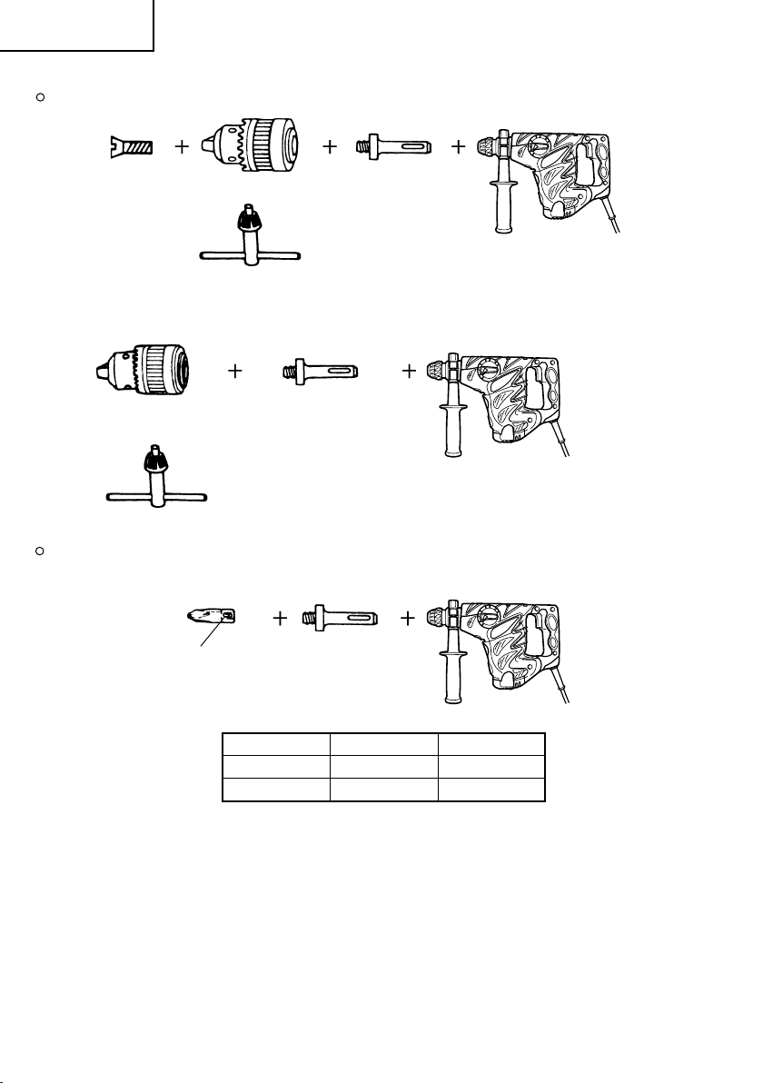
Nederlands
8. Boren van gaten en aandraaien van schroeven (Alleen Boren)
Boorkop, boorkopadaptor (G), speciale schroef en sleutel
Boorkop (13 VLRB-D)Sppeciale schroef
Sleutel
9. Boren van gaten (Alleen boren)
Boorkop (13 VLD-D)
Sleutel
13 mm boorkop (met speciale sleutel) en boorkopadapter (voor het boren in staal of hout.)
10. Drijven van schroeven (Alleen boren)
Boorstuk Nr.
Boorkopadaptor (D)
(SDS Plus schacht)
Boorkopadaptor (D)
(SDS Plus schacht)
Boorkopadaptor (G)
(SDS Plus schacht)
Boorstuk Nr. Schroefmaat Lengte
Nr.2 3 – 5 mm 25 mm
Nr.3 6 – 8 mm 25 mm
11. Hammer Grease A
500 gr. (in een blik)
70 gr. (in een groene tube)
30 gr. (in een groene tube)
De extra toebehoren kunnen zonder aankondiging op ieder moemnt worden veranderd.
45
Page 47

Nederlands
TOEPASSINGEN
Boren en kloppen
Boren van ankergaten
Boren van gaten in beton
Boren van gaten in tegels
Alleen draaien
Boren in staal of hout (met los verkrijgbare
toebehoren)
Vastdraaien van machine-schroeven, houtschroeven
(met los verkrijgbare toebehoren)
Alleen kloppen
Licht beitelen van beton, groefsnijden en graven
VOOR HET GEBRUIK
1. Netspanning
Controleren of de netspanning overeenkomt met de
opgave op het naamplaatje.
2. Netschakelaar
Controleren of de netschakelaar op „UIT” staat.
Wanneer de stekker op het net aangesloten is, terwijl
de schakelaar op „AAN” staat, begint het
gereedschap onmiddellijk te draaien, hetwelk ernstig
gevaar betekent.
3. Verlengsnoer
Wanneer het werkterrein niet in de buurt van een
stopcontact ligt, dan moet men gebruik maken van
een verlengsnoer, dat voldoende dwarsprofiel en
voldoende nominaal vermogen heeft. Het
verlengsnoer moet zo kort mogelijk gehouden
worden.
4. Bevestigen van het boorstuk (Afb. 1)
LET OP
Om ongevallen te voorkomen, schakelt u de
schakelaar uit en koppelt u de stekker los van het
net.
OPMERKING
Wanneer u gereedschap zoals puntboren,
boorstukken, enz. gebruikt, gebruik altijd de originele
onderdelen aangeduid door ons bedrijf.
(1) Maak de schacht van het boorstuk schoon.
(2) Om een boorstuk (SDS Plus schacht) te bevestigen,
de greep volledig in de richting van de pijl trekken
zoals aangegeven in Afb. 1 en vervolgens het
boorstuk al draaiend naar binnen steken tot dit ver
genoeg zit.
(3) Door de greep los te laten wordt het boorstuk
vastgeklemd.
(4) Om het boorstuk te verwijderen, de greep volledig
in de richting van de pijl trekken en vervolgens het
boorstuk naar buiten trekken.
5. Installatie van de stofvangkap (optionele accessoires)
(Afb. 2)
Wanneer u een boorhamer gebruikt om opwaarts
te boren, bevestig dan een stofvangkap om stof en
deeltjes op te vangen voor een gemakkelijke
bediening.
Aanbrengen van de stofvangkap
Breng de stofvangkap voor het gebruik aan op de
boorkop, zoals aangegeven in Afb. 2.
Voor het aanbrengen op een boorkop met een grote
diameter kunt u het middengat van de stofvangkap
vergroten door het voorzichtig met de boorhamer
uit te boren.
VOORZICHTIG:
De stofvangkap mag alleen worden gebruikt voor
boren in beton. Gebruik ze niet om te boren in hout
of metaal.
Leeg de stofverzamelaar (B) telkens na het boren
van twee of drie gaten.
6. Kiezen van aandrijfstuk
Schroefkoppen of boren kunnen beschadigd worden
indien een voor de diameter van de schroef verkeerd
boorstuk wordt gebruikt om de schroef vast te
draaien.
7. Kiezen van de functie-instelling
U kunt wisselen tussen functies van de 3 modi
„
alleen kloppen“, „boren en kloppen“ en „alleen
“
door met de keuzeschakelaar te draaien
boren
terwijl u de druktoets ingedrukt houdt.
merkteken op de keuzehendel op de functie die u
wilt gebruiken.
VOORZICHTIG:
Voor u de keuzehendel gebruikt, moet u controleren
of de motor volledig tot stilstand is gekomen. Als
u de hendel verzet terwijl de motor nog draait, kan
de machine kapot gaan.
Voor u de keuzehendel kunt verzetten, dient u eerst
de knop in te drukken om de vergrendeling op te
heffen. Na verzetten van de hendel dient u te
controleren of de drukknop is teruggekeerd in zijn
uitgangspositie en of de keuzehendel vergrendeld
is.
Zet de keuzehendel volledig in de gewenste stand.
Als u de hendel halverwege tussen twee standen
zet, kan de levensduur van het schakelmechanisme
aanmerkelijk bekort worden.
Zet het ▲
GEBRUIK
VOORZICHTIG:
Om ongevallen te voorkomen schakelt u de schakelaar
uit en trekt u de stekker uit het stopcontact wanneer
boorstukken of andere onderdelen worden geïnstalleerd
of verwijderd. De voedingsschakelaar moet ook worden
uitgeschakeld tijdens een werkpauze of na het werk.
1. Bediening van de schakelaar
Het toerental van de boor kan door verandering van
de druk op de drukschakelaar geregeld worden.
De snelheid is gering, wanneer de drukschakelaar
slechts licht getrokken is en verhoogt zich, wanneer
de schakelaar verder doorgetrokken wordt.
2. Boren + kloppen
Deze boorhamer kan worden ingesteld om te boren
en te kloppen door op de druktoets te drukken en
de keuzeschakelaar naar de markering
(Afb. 3).
Draai lichtjes met de greep en controleer dat ze
vastzit met een klik.
(1) Bevestig de boor.
(2) Plaats de punt van de boor op de gewenste positie
en trek aan de schakelaar. (Afb. 4)
(3) Het is niet nodig met kracht tegen de boorhamer
te drukken. Lichtjes drukken zodat de stukjes naar
buiten komen is reeds voldoende.
VOORZICHTIG:
Als het boorstuk vast komt te zitten in een ijzeren
stang, kan de boorhamer hevi gaan schudden. Zorg
er daarom voor dat beide handgrepen goed worden
vastgehouden zoals aangegeven in Afb. 4.
te draaien
46
Page 48

Nederlands
3. Alleen draaien
Door op de druktoets te drukken en de keuzehendel
naar de
in de functie voor uitsluitend roteren worden gesteld.
(Afb. 5)
Draai lichtjes met de greep en controleer dat ze
vastzit met een klik.
Ga als volgt te werk voor het boren in hout of
metaal met behulp van de boorkop en
boorkopadaptor (extra toebehoren).
Bevestigen van de boorkop en boorkopadaptor:
(Afb. 6)
(1) Bevestig de boorkop aan de boorkopadaptor.
(2) Het onderdeel van de SDS Plus schacht is hetzelfde
als een boorstuk. Zie daarom het gedeelte
“Bevestigen van het boorstuk” om dit deel te
bevestigen.
VOORZICHTIG:
Het is niet nodig met kracht tegen de boorhamer
te drukken. Wordt ditrmatige slij-tage van de punt
van het boorstuk en een kortere levensduur van de
boorhamer.
Boorstukken kunnen losschieten bij het terugtrekken
van de boorhamer uit het geboorde gat. U kunt de
boorhamer terugtrekken met een drukkende
beweging.
Probeer geen ankergaten te boren of gatenin beton
terwijl de machine in de „alleen draaien” functie
is.
Gebruik de boorhamer niet om te boren en te
kloppen met de boorkop en boorkopadaptor
bevestigd.
4. Drijven van machineschroeven (Afb. 7)
Steek eerst het schroefstuk in de aansluitbus die
zich aan het uiteinde van het kopadaptor (D) bevindt.
Bevestig vervolgens het kopadaptor (D) op het
apparaat zoals beschreven in 4 (1), (2), (3). Plaats
de top van het schroefstuk in de gleuven van de
kop van de schroef. Pak het apparaat stevig beet
en draai de schoef vast.
VOORZICHTIG:
Zorg ervoor dat de schroef niet al te lang wordt
aangedraaid, omdat de schroef beschadigd zou
kunnen worden.
Zet de boorhamer recht op de schroef wanneer
deze wordt aangedraaid; wanneer dit niet gedaan
wordt kan de kop van de schroef beschadigd worden.
De draaikracht kan ook onvoldoende op de schroef
worden overebracht.
Gebruik de boorhamer niet om te boren en te
kloppen met de boorkopadaptor en het boorstuk
bevestigd.
5. Aandraaien van houtschroeven (Afb. 7)
(1) Kiezen van de juiste boorpunt
Gebruik indien mogelijk altijd een plus-kop schroef
omdat een boorpunt gemakkelijk van een min-kop
schroef afglijdt.
(2) Aandraaien van houtschroeven
Maak een gat in de oppervlakte van het hout voordat
de houtschroef ingedraaid wordt. Zet de punt van
de boor op de kop van de schroef en draai deze
langzaam naar binnen.
Draai de boorhamer eerst langzaam totdat deschroef
gedeeltelijk is ingedreven, en trek dan verder aan
de schakelaar om optimale drijfkracht te verkrijgen.
markering te draaien, kan deze boorhamer
VOORZICHTIG:
Neem voorzichtigheid in acht bij het maken van een
gat voor de schroef; met de hardheid van het hout
dient rekening gehouden te worden. Als het gat te
klein is, of te ondiep, hetgeen meer drijfkracht vereist,
kan het schroefdraad van de schroef beschadigd
worden.
6. Alleen kloppen
Deze boorhamer kan worden ingesteld om alleen
te boren door op de druktoets te drukken en de
keuzeschakelaar naar de markering
(Afb. 8).
(1) Bevestig de puntboor of beitel.
(2) Duw op de druktoets en stel de keuzeschakelaar in
op de markering
Wanneer de rotatie is ontgrendeld, moet u de greep
verdraaien en de beitel in de gewenste stand stellen.
(Afb. 10)
(3) Draai de keuzehendel met een pen of dergelijk naar
7. Gebruik van de stopper (Afb. 11)
(1) Draai de zijhendel los en steek de stopper in het
(2) Bepaal de positie van de stopper overeenkomstig
8. Gebruik van het boorstuk (met vernauwde schacht)
(1) Bevestig de vernauwde schachtadaptor aan de
(2) Bevestig het boorstuk (met vernauwde schacht) aan
(3) Schakel de boorhamer in en boor een gat van de
(4) Voor het verwijderen van het boorstuk (met
9. Gebruik van de zijhendel
VOORZICHTIG:
markering. (Afb. 8)
de
De beitel is nu vergrendeld.
gat voor de greepbout.
de diepte van het gaten draai de zijhendel stevig
vast.
en de vernauwde schachtadaptor
boorhamer. (Afb. 12)
de vernauwde schachtadapter. (Afb. 12).
gewenste diepte.
vernauwde schacht) dient de cotter in de gleuf van
de vernauwde schachtadaptor te worden gestoken.
Sla nu op de cotter terwijl de boorhamer wordt
ondersteund. (Afb. 13)
Als u de stand van de zijhendel wilt veranderen,
dient u de greep van de zijhandel tegen de klok
in los te draaien en vervolgens in de gewenste
stand weer goed vast te zetten.
Wanneer u een gat aan het boren bent, is het
mogelijk dat de machine probeert te draaien als
reactie op de kracht van de boor wanneer deze door
een betonnen muur breekt en/of wanneer de punt
van de boor een stang betonijzer raakt.
Maak daarom de zijhendel goed vast en houd de
machine met beide handen vast. Doet u dit niet,
dan kunnen er ongelukken gebeuren.
. (Afb. 9)
te draaien
GEBRUIK VAN HET KERNSTUK
(VOOR LICHTE BELASTING)
Met behuip van het kernstuk (voor lichte balasting)
kunnen grote kaliber gaten geboord worden. Gebruik
het kernstuk samen met de los verkrygbare en de
kernstukschacht.
1. Monteren
VOORZICHTIG
Schakel de boorhamer uit en trek de stekker uit het
stopcontact.
47
Page 49

Nederlands
(1) Bevestig het kernstuk aan de kernstukschacht.
(Afb. 14)
Bedek de schroefdraad van de kernstukschacht
met vet om naderhand het demonteren te
vergemakkelijken.
(2) Bevestig de kernstukschacht aan de boorhamer.
(Afb. 15)
(3) Steek de middenpin zo ver mogelijk in het pasplaatje.
(4) Leg het pasplaatje op het kernstuk en draai het
links-of rechtsom zodat het niet uit positie kan raken,
zelfs als het kernstuk naar beneden wordt gericht.
(Afb. 16)
2. Boren (Afb. 17)
(1) Steek de stekker in het stopcontact.
(2) De middenpen heeft een ingebouwde veer.
Duw deze recht en zachtjes tegen een muur of
vloer.
Door deze recht en zachtjes tegen een muur of vloer
te drukken maakt de oppervlakte van het kernstuk
contact waarna een gat geboord kan worden.
(3) Als de diepte van het gat ongeveer 5 mm bedraagt,
kan de positie van het gat bepaald worden. Verwijder
hierna de middenpin en het plaatje en boor
vervolgens het gat.
(4) Het is niet nodig met kracht tegen de boorhamer
te drukken. Wordt dit wel gedaan, dan zal dit
resulteren in overmatige slijtage van de punt van
het boorstuk en een kortere levensduur van de
boorhamer.
VOORZICHTIG
Schakel de boorhamer uit en trek de stekker uit het
stopcontact alvorens de middenpin en het plaatje
te verwijderen.
3. Demonteren (Afb. 18)
Neem de kernstukschacht uit de boorhamer en sla
twee of drie keer hard met een hamer op de kop
van de kernstukschacht. Het kernstuk kan nu
verwijderd worden.
VERVANGEN VAN DE OLIE
Dit apparaat is volledig luchtdicht gemaakt om te
voorkomen dat er stof binnendringt of smeermiddelen
lekken. Het gereedschap kan worden gebruikt zonder
regelmatig olie (smeermiddel) toe te voegen. U moet
echter na langdurig gebruik de olie vervangen om de
levensduur van het gereedschap te verlengen. Voer de
volgende handelingen hiervoor uit.
1. Periodieke vervanging van de olie
U moet het vet bekijken wanneer u de koolborstel
vervangt. (Zie onderdeel 4 in het gedeelte
ONDERHOUD EN INSPECTIE.) Vervangingsolie is
verkrijgbaar bij de officiele Hitachi Service Agent.
In het geval dat u de smeerolie zelf moet vervangen,
gaat u als volgt te werk.
2. Verwisselen van de olie
VOORZICHTIG:
Zet het apparaat uit, en verwijder de stekker uit het
stopkontakt voordat met het vervangen van de olie
begonnen wordt.
(1) Demonteer de bedekking en veeg de aanwezige
oude smeerolie goed weg (Fig. 19).
(2) Voeg 30 g Hitachi Electric Hammer Grease A
(standaard hoeveelheid, in tube) toe aan de
bedekking.
(3) Herplaats de bedekking op de juiste manier nadat
de olie vervangen is. Wees voorzichtig zodat de die-
afdichting niet wordt heschadiad af gelozt.
OPMERKING:
De Hitachi Electric Hammer Grease A is van het lage
viscositeitstype. Wanneer de tube opgebruikt is, kan
een nieuwe tube bij de Hitachi Service Agent
verkregen worden.
ONDERHOUD EN INSPECTIE
1. Inspectie van de boor
Versleten boren dienen onmiddelijk vervangen of
geslepen te worden, daar gebruik van versleten
boren kan resulteren in verminderde efficiëntie en
defekten aan de motor.
2. Inspectie van de bevestigingsschroef
Alle bevestigingsschroeven moten regelmatig
geïnspecteerd en gecontroleerd worden of zij juist
aangedraaid zijn. Wanneer één van de schroeven
losraakt, dan moet deze onmiddellijk opnieuw
aangedraaid worden. Gebeurt dat niet, dan kan dat
tot aanzienlijke gevaren leiden.
3. Onderhoud van de motor
De motorwikkeling is het „hart” van het electrische
gereedschap. Er moet daarom bijzonder zorgvuldig
op gelet worden, dat de wikkeling niet beschadigd
en/of met olie of water bevochtigd wordt.
4. Inspecteren van de koolborstels
Met het oog op uw veiligheid en om elektrische
schokken te voorkomen, mag inspectie en
vervanging van de koolborstels ALLEEN uitgevoerd
worden door een ERKEND HITACHI SERVICE-
CENTRUM.
5. Voedingssnoer vervangen
Als het voedingssnoer van het gereedschap
beschadigd is, moet het gereedschap worden
terugbezorgd aan een erkend Hitachi servicecenter
om het snoer te vervangen.
6. Lijst vervangingsonderdelen
A: Ond.nr.
B: Codenr.
C: Gebr.nr.
D: Opm.
VOORZICHTIG
Reparatie, modificatie en inspectie van Hitachi
elektrisch gereedschap dient te worden uitgevoerd
door een erkend Hitachi Service-centrum.
Deze Onderdelenlijst komt van pas wanneer u deze
samen met het gereedschap aanbiedt bij het erkende
Hitachi Service-centrum wanneer u om reparatie of
ander onderhoud verzoekt.
Bij gebruik en onderhoud van elektrisch gereedschap
dienen de in het land waar u zich bevindt geldende
veiligheidsregelgeving en veiligheidsstandaarden
stipt te worden opgevolgd.
MODIFICATIES
Hitachi elektrisch gereedschap wordt voortdurend
verbeterd en gewijzigd teneinde gebruik te kunnen
maken van de nieuwste technische ontwikkelingen.
Daarom is mogelijk dat sommige onderdelen (zoals
codenummers en/of ontwerp) zonder voorafgaande
kennisgeving gewijzigd worden.
48
Page 50

Nederlands
GARANTIE
We garanderen dat elektrisch gereedschap van Hitachi
overeenstemt met de wettelijke/landenspecifieke
regelgeving. Deze garantie dekt geen defecten of schade
wegens verkeerd gebruik, misbruik of normale slijtage.
In geval van klachten, stuurt u het elektrische
gereedschap, niet uit elkaar gehaald, met het
GARANTIECERTIFICAAT dat zich bevindt op het einde
van deze bedieningsinstructies, naar een erkend Hitachi
servicecenter.
AANTEKENING:
Op grond van het voortdurende research- en
ontwikkelingsprogramma van HITACHI zijn
veranderingen van de hierin genoemde technische
opgaven voorbehouden.
Informatie betreffende luchtgeluid en trillingen
De gemeten waarden zijn verkregen overeenkomstig
EN60745 en voldoen aan de eisen van ISO 4871.
Gemeten A-gewogen geluidsniveau: 100 dB (A)
Gemeten A-gewogen geluidsdrukniveau: 89 dB (A)
Onzekerheid KpA: 3 dB (A)
Draag gehoorbescherming.
Totale trillingswaarden (triax vector som) bepaald
overeenkomstig EN60745.
Boorhameren in beton:
Trillingsemissiewaarde
Onzekerheid K = 1,9 m/s2 (A)
Beitelen:
Trillingsemissiewaarde
Onzekerheid K = 6,5 m/s2 (A)
Geen belasting:
Trillingsemissiewaarde
Onzekerheid K = 3,0 m/s2 (A)
Equivalente waarde beitelen:
Trillingsemissiewaarde
Onzekerheid K = 6,5 m/s2 (A)
ah, HD = 19,8 m/s
ah, CH = 13,6 m/s
ah, NL = 4,2 m/s
ah, CHeq = 12,3 m/s
2
2
2
2
WAARSCHUWING
䡬 De trillingsemissiewaarde tijdens het feitelijke
gebruik van het elektrisch gereedschap kan afwijken
van de opgegeven waarde afhankelijk van de
manieren waarop het gereedschap wordt gebruikt.
䡬 Neem kennis van de veiligheidsmaatregelen voor
de bescherming van de operator welke gebaseerd
zijn op een schatting van blootstelling onder feitelijke
gebruiksomstandigheden (rekening houdend met alle
onderdelen van de gebruikscyclus, zoals de tijd dat
het gereedschap is uitgeschakeld en wanneer dit
onbelast draait inclusief de triggertijd).
49
Page 51

Español
ADVERTENCIAS DE SEGURIDAD GENERAL
DE LA HERRAMIENTA ELÉCTRICA
ADVERTENCIA
Lea todas las instrucciones y advertencias de seguridad.
Si no se siguen las advertencias e instrucciones, podría
producirse una descarga eléctrica, un incendio y/o daños
graves.
Guarde todas las advertencias e instrucciones para futura
referencia.
El término “herramienta eléctrica” en las advertencias
hace referencia a la herramienta eléctrica que funciona
con la red de suministro (con cable) o a la herramienta
eléctrica que funciona con pilas (sin cable).
1) Seguridad del área de trabajo
a) Mantenga la zona de trabajo limpia y bien iluminada.
Las zonas desordenadas u oscuras pueden
provocar accidentes.
b) No utilice las herramientas eléctricas en entornos
explosivos como, por ejemplo, en presencia de
líquidos inflamables, gases o polvo.
Las herramientas eléctricas crean chispas que
pueden inflamar el polvo o los humos.
c) Mantenga a los niños y transeúntes alejados
cuando utilice una herramienta eléctrica.
Las distracciones pueden hacer que pierda el control.
2) Seguridad eléctrica
a) Los enchufes de las herramientas eléctricas tienen
que ser adecuados a la toma de corriente.
No modifique el enchufe.
No utilice enchufes adaptadores con herramientas
eléctricas conectadas a tierra.
Si no se modifican los enchufes y se utilizan tomas
de corriente adecuadas se reducirá el riesgo de
descarga eléctrica.
b) Evite el contacto corporal con superficies conectadas
a tierra como tuberías, radiadores y frigoríficos.
Hay mayor riesgo de descarga eléctrica si su
cuerpo está en contacto con el suelo.
c) No exponga las herramientas eléctricas a la lluvia
o a la humedad.
La entrada de agua en una herramienta eléctrica
aumentará el riesgo de descarga eléctrica.
d) No utilice el cable incorrectamente. No utilice el
cable para transportar, tirar de la herramienta
eléctrica o desenchufarla.
Mantenga el cable alejado del calor, del aceite, de
bordes afilados o piezas móviles.
Los cables dañados o enredados aumentan el
riesgo de descarga eléctrica.
e) Cuando utilice una herramienta eléctrica al aire
libre, utilice un cable prolongador adecuado para
utilizarse al aire libre.
La utilización de un cable adecuado para usarse
al aire libre reduce el riesgo de descarga eléctrica.
f) Si no se puede evitar el uso de una herramienta
eléctrica en un lugar húmedo, utilice un suministro
protegido mediante un dispositivo de corriente
residual (RCD).
El uso de un RCD reduce el riesgo de descarga
eléctrica.
3) Seguridad personal
a) Esté atento, preste atención a lo que hace y utilice
el sentido común cuando utilice una herramienta
eléctrica.
No utilice una herramienta eléctrica cuando esté
cansado o esté bajo la influencia de drogas,
alcohol o medicación.
La distracción momentánea cuando utiliza
herramientas eléctricas puede dar lugar a
importantes daños personales.
b) Utilice un equipo de protección. Utilice siempre
una protección ocular.
El equipo de protección como máscara para el
polvo, zapatos de seguridad antideslizantes, casco
o protección para oídos utilizado para condiciones
adecuadas reducirá los daños personales.
c) Evite un inicio involuntario. Asegúrese de que el
interruptor está en “off” antes de conectar la
herramienta a una fuente de alimentación y/o
batería, cogerla o transportarla.
El transporte de herramientas eléctricas con el
dedo en el interruptor o el encendido de
herramientas eléctricas con el interruptor
encendido puede provocar accidentes.
d) Retire las llaves de ajuste antes de encender la
herramienta eléctrica.
Si se deja una llave en una pieza giratoria de la
herramienta eléctrica podrían producirse daños
personales.
e) No se extralimite. Mantenga un equilibrio
adecuado en todo momento.
Esto permite un mayor control de la herramienta
eléctrica en situaciones inesperadas.
f) Vístase adecuadamente. No lleve prendas sueltas
o joyas. Mantenga el pelo, la ropa y los guantes
alejados de las piezas móviles.
La ropa suelta, las joyas y el pelo largo pueden
pillarse en las piezas móviles.
g) Si se proporcionan dispositivos para la conexión
de extracción de polvo e instalaciones de recogida,
asegúrese de que están conectados y se utilizan
adecuadamente.
La utilización de un sistema de recogida de polvo
puede reducir los riesgos relacionados con el polvo.
4) Utilización y mantenimiento de las herramientas
eléctricas
a) No fuerce la herramienta eléctrica. Utilice la
herramienta eléctrica correcta para su aplicación.
La herramienta eléctrica correcta trabajará mejor
y de forma más segura si se utiliza a la velocidad
para la que fue diseñada.
b) No utilice la herramienta eléctrica si el interruptor
no la enciende y apaga.
Las herramientas eléctricas que no pueden
controlarse con el interruptor son peligrosas y
deben repararse.
c) Desconecte el enchufe de la fuente eléctrica y/o
la batería de la herramienta eléctrica antes de
hacer ajustes, cambiar accesorios o almacenar
herramientas eléctricas.
Estas medidas de seguridad preventivas reducen
el riesgo de que la herramienta eléctrica se ponga
en marcha accidentalmente.
d) Guarde las herramientas eléctricas que no se
utilicen para que no las cojan los niños y no
permita que utilicen las herramientas eléctricas
personas no familiarizadas con las mismas o con
estas instrucciones.
Las herramientas eléctricas son peligrosas si son
utilizadas por usuarios sin formación.
50
Page 52

Español
e) Mantenimiento de las herramientas eléctricas.
Compruebe si las piezas móviles están mal
alineadas o unidas, si hay alguna pieza rota u
otra condición que pudiera afectar al
funcionamiento de las herramientas eléctricas.
Si la herramienta eléctrica está dañada, llévela a
reparar antes de utilizarla.
Se producen muchos accidentes por no realizar un
mantenimiento correcto de las herramientas eléctricas.
f) Mantenga las herramientas de corte afiladas y limpias.
Las herramientas de corte correctamente
mantenidas con los bordes de corte afilados son
más fáciles de controlar.
g) Utilice la herramienta eléctrica, los accesorios y las
brocas de la herramienta, etc. de acuerdo con estas
instrucciones, teniendo en cuenta las condiciones
laborales y el trabajo que se va a realizar.
La utilización de la herramienta eléctrica para
operaciones diferentes a aquellas pretendidas
podría dar lugar a una situación peligrosa.
5) Revisión
a) Lleve su herramienta a que la revise un experto
cualificado que utilice sólo piezas de repuesto idénticas.
Esto garantizará el mantenimiento de la seguridad
de la herramienta eléctrica.
ESPECIFICACIONES
Voltaje (por áreas)* (110 V, 115 V, 120 V, 127 V, 220 V, 230 V, 240 V)
Acometida 850 W*
Velocidad sin carga 0 – 850 min
Velocidad de percusión a carga plena 0 – 3700 min
Capacidad: hormigón 4 – 30 mm
Peso (sin cable ni mango lateral) 4,3 kg
*Verificar indefectiblemente los datos de la placa de características de la máquina, pues varían de acuerdo
con el país de destino.
acero 13 mm
madera 32 mm
PRECAUCIÓN
Mantenga a los niños y a las personas enfermas alejadas.
Cuando no se utilicen, las herramientas deben almacenarse
fuera del alcance de los niños y de las personas enfermas.
PRECACIONES A LA HORA DE UTILIZAR EL
MARTILLO PERFORADOR
1. Utilice protectores auditivos
La exposición al ruido puede provocar una pérdida
de audibilidad.
2. Utilice los mangos auxiliares incluidos con la
herramienta.
La pérdida de control puede provocar lesiones
personales.
3. No toque la broca cuando la herramienta esté en
marcha o inmediatamente después de utilizarla.
La broca se caliente mucho al utilizarla y puede
provocar quemaduras graves.
4. Antes de empezar a romper, picar o perforar una
pared, suelo o techo, compruebe cuidadosamente
que no haya objetos empotrados como cables o
conductos eléctricos.
5. Sujete siempre el mango lateral y el del cuerpo
de la herramienta mecánica firmemente. De lo
contrario, la contrafuerza que se genera podría
provocar un control impreciso e incluso peligroso.
6. Utilice una máscara contra el polvo
No inhale las partículas de polvo nocivas
producidas al perforar o cincelar. Las partículas
de polvo pueden constituir un perjuicio para su
propia salud y la de las personas cercanas al lugar
de trabajo.
ACCESORIOS ESTÁNDAR
(1) Caja de plástico ........................................................ 1
(2) Mango lateral ............................................................. 1
(3) Tope ............................................................................. 1
(4) Copa de polvo ........................................................... 1
(5) Jeringa ........................................................................ 1
Los accesorios estándar están sujetos a cambio sin previo
aviso.
ACCESORIOS FACULTATIVOS (de venta por separado)
1. Perforación de orificios de anclaje (rotación + percusión)
Broca de taladro (vástago cónico) y adaptador cónico
Broca de taladro (Vástago cónico)
51
Adaptador cónico
(SDS plus vástago)
Chaveta
Page 53

Español
Diámetro externo
11,0 mm
12,3 mm
12,7 mm
14,3 mm
14,5 mm
17,5 mm
21,5 mm
2. Montaje del ancla (únicamente percusión)
Adaptador de montaje de ancla (para martillo perforador)
Adaptador de montaje de ancla (SDS plus vástago)
(para martillo perforador)
Longitud total: 160 mm, 260 mm
Medida de ancla
W1/4"
W5/16"
W3/8"
Adaptador de montaje de ancla (para martillo manual)
Medida de ancla
W1/4"
W5/16"
W3/8"
W1/2"
W5/8"
Modo cónico Broca de taladro aplicable
Cono Morse (No.1)
Cono Morse (No.2)
Cono A El cono A o B troquelado del adaptador cónico ha
Cono B pero la broca para el mismo no se suministra.
Broca de taladro
(vástago cónico)
Broca de taladro
(vástago cónico)
sido suministrado como accesorio facultativo
Adaptador de montaje de ancla
(para martillo manual)
11,0 ~ 17,5 mm
21,5 mm
3. Perforación de orificios anchos (rotación + percusión)
Pasador central, barrena tubular, espiga de la barrena tubular y placa guía.
(Placa
guia)
No usar barrenas tubulares Con placa guía
con un diámetro externo de (La placa guía no se ha equipado con barrenas
25 mm y 29 mm. tubulares con diámetro externo de 25 mm y 29 mm.)
Pasador central Barrena
Pasador central Barrena tubular (diámetro externo) Espiga de la barrena tubular
–
Pasador central (A) 35 mm
Pasador central (B) (B)
tubular
(A) 32 mm
Espiga de la barrena
tubular
(SDS plus vástago)
25 mm
29 mm
38 mm
45 mm
50 mm
65 mm Espiga de la barrena tubular (B)
80 mm
90 mm
Espiga de la barrena tubular (A)
52
Page 54

Español
4. Demolición (únicamente percusión)
Puntero (Tipo redondo) (SDS plus vástago)
Puntero (Tipo cuadrado) (SDS plus vástago)
5. Excavación de ranuras y rebordes (únicamente percusión)
Cortafrio (SDS plus vástago)
Cargadora (SDS plus vástago)
6. Ranurado (únicamente percusión)
Cincel de ranuración (SDS plus vástago)
7. Colocación de pernos con anclaje químico (rotación + percusión)
(Manguito
adaptador
a la venta
en el mercado)
8. Perforación y colocación de tornillos (rotación solamente)
Portabrocas, adaptador (G) del portabrocas, tornillo especial y llave de portabrocas
Tornillo especial
53
Adaptador de anclaje químico de 12,7 mm
Adaptador de anclaje químico de 19 mm
(SDS plus vástago)
Porabrocas
(13 VLRB-D)
Llave de portabrocas
Adaptador (G) de portabrocas
(SDS plus vástago)
Page 55

9. Perforación (rotación solamente)
Español
Portabrocas (13 VLD-D)
Llave de portabrocas
Conjunto de portabrocas 13 mm (con llave de portabrocas) y portabrocas (para perforación de orificios en
hormigón o madera.)
10. Colocación de tornillos (rotación solamente)
No. de broca
11. Grasa A para martillo
500 g (en una lata)
70 g (en un tubo naranja)
30 g (en un tubo naranja)
Los accesorios de norma están sujetos a cambio sin previo aviso.
APPLICACIÓN
Funciones de rotación y percusión
Perforación de orificios de anclaje
Perforación de orificios de hormigón
Perforación de orificios de baldosa
Rotación solamente
Perforación de orificios en hormigón o madera
(con accesorios facultativos)
Apretar tornillos en metal o madera.
(con accesorios facultativos)
Función únicamente de percusión
Cincelado leve de hormigón, ranuración, y retoque
de bordes
ANTES DE LA PUESTA EN MARCHA
1. Alimentación
Asegurarse de que la alimentación de red que ha
de ser utilizada responda a las exigencias de
corriente especificadas en la placa de características
del producto.
Adaptador (D) del portabrocas
(SDS plus vástago)
Adaptador (D) del portabrocas
(SDS plus vástago)
No. de broca
No.2 3 – 5 mm 25 mm
No.3 6 – 8 mm 25 mm
Tamaño del tornillo
2. Conmutador de alimentación
Asegurarse de que el conmutador de alimentación
esté en la posición OFF (desconectado). Si la clavija
está conectada en la caja del enchufe mientras el
conmutador de alimentación esté en posición ON
(conectado) las herramientas eléctricas empezarán
a trabajar inmediatamente, provocando un serio
accidente.
3. Cable de prolongación
Cuando está alejada el área de trabajo de la red
de alimentación, usar un cable de prolongación de
un grosor y potencia nominal suficiente. El cable
de prolongación debe ser mantenido lo más corto
posible.
4. Montaje de la broca (Fig. 1)
AVISO
Con el fin de evitar accidentes, asegúrese de apagar
el interruptor y desconectar el enchufe del
receptáculo.
NOTA
Cuando utilice herramientas como punteros, brocas,
etc., asegúrese de que sean piezas originales
diseñadas por nuestra empresa.
Longitud
54
Page 56

Español
(1) Limpie la espiga de la broca.
(2) Para colocar una broca (SDS plus vástago), tire
completamente de la empuñadura en el sentido de
la flecha como se muestra en la Fig. 1 e inserte
profundamente la broca girándola.
(3) Al soltar la empuñadura, la broca quedará asegurada.
(4) Para extraer la broca, tire completamente de la
empuñadura en el sentido de la flecha y tire hacia
afuera de la broca.
5. Instalación del colector de polvo (accesorios
opcionales) (Fig. 2)
Cuando utilice un martillo perforador para perforar
hacia arriba, acople un colector de polvo para recoger
el polvo y otras partículas y trabajar con mayor
comodidad.
Instalación de la copa de polvo
Emplee la copa de polvo instalando la broca como
se muestra en la Fig. 2.
Cuando emplee una broca de gran diámetro, agrande
el orificio central de la copa de polvo con este
martillo perforador.
PRECAUCIÓN:
El colector de polvo debe utilizarse exclusivamente
en trabajos de perforación de hormigón. No lo
utilice para perforar madera o metal.
Durante el taladrado, vacíe las partículas de polvo
después de taladrar dos o tres orificios.
6. Selección de la broca destornilladora
Las cabezas de tornillos y las brocas de atornillar
se dañarán menos cuando se emplee la broca
apropiada según sea el diámetro del tornillo.
7. Selección del modo de función
Puede seleccionar cualquiera de las 3 funciones
(“únicamente percusión”, “rotación + percusión” y
“únicamente rotación”) girando la palanquita
selectora mientras mantiene presionado el pulsador.
Colocar la marca de la palanca de cambio frente
a la marca ▲ correspondiente al modo que desea
usar.
PRECAUCIÓN:
Antes de operar la palanca de cambio, comprobar
que el motor esté detenido.
De accionar la palanca con el motor funcionando,
podría producirse una avería.
Para operar la palanca de cambio, presionar el
pulsador y desbloquear la palanca de cambio.
Asimismo, después de la operación, comprobar el
retorno del pulsador y el bloqueo de la palanca de
cambio.
Conmutar correctamente la palanca de cambio. De
utilizarla en una posición intermedia, existe el riesgo
de que se acorte la vida útil del mecanismo de
conmutación.
COMO SE USA
PRECAUCIÓN:
Con el fin de evitar accidentes, asegúrese de apagar la
máquina y de desconectar el enchufe del receptáculo
cuando coloque o retire brocas y otras piezas. El
interruptor de alimentación eléctrica también debe
apagarse al realizar pausas y al finalizar el trabajo.
1. Operación del conmutador
La velocidad rotatoria de la broca de taladro puede
ser controlada variando la fuerza con la que se
aprieta el pulsador. La velocidad está baja cuando
se aprieta ligeramente el pulsador y se aumenta al
apretar más el pulsador.
2. Rotación + percusión
El martillo perforador puede fijarse en el modo de
rotación y percusión presionando el pulsador y
girando la palanquita selectora hasta la
(Fig. 3)
Gire ligeramente el sujetador y espere a oír un clic
para confirmar que el embrague está engranado.
(1) Montar la broca.
(2) Presionar el interruptor de gatillo después de poner
la punta de la broca en la posición para taladrar.
(Fig. 4)
(3) No es necesario presionar con fuerza la broca.
Presionar ligeramente la broca de forma que el
polvo producido al taladrar salga al exterior
gradualmente.
PRECAUCIÓN:
Cuando la broca toque una barra de hierro de
construción se detendrá inmediatamente y el martillo
perforador tenderá a girar. Por lo tanto, sujetar el
mango lateral y sostenerlo firmemente como se
ilustra en la Fig. 4.
3. Rotación solamente
Este martillo perforador puede usarse en el modo
de rotación solamente presionando el pulsador y
girando la palanca selectora hasta la marca
(Fig. 5)
Gire ligeramente el sujetador y espere a oír un clic
para confirmar que el embrague está engranado.
Para perforar madera o metal empleando el
portabrocas y el adaptador del portabrocas
(accesorio facultativo), proceder como sigue.
Instalación del portabrocas y adaptador del
portabrocas: (Fig. 6)
(1) Acople el portabrocas al adaptador de portabrocas.
(2) La parte del SDS plus vástago es igual que una
broca. Por lo tanto, para instalarla, consulte ”Montaje
de la broca”.
PRECAUCIÓN:
La aplicación de fuerza excesiva acelerará el trabajo
pero dañará la punta de la broca y reducirá la vida
útil del martillo perforador.
La broca puede desprenderse al retirar el martillo
perforador del agujero perforado. Para retirar el
martillo, es importante realizar un movimiento de
empuje.
No intentar perforar orificios de anclaje o perforar
el concreto con la máquina puesta en la función
de rotación solamente.
No intente utilizar el martillo perforador para la
función de rotación y percusión con el portabrocas
y el adaptador de portabrocas acoplados.
Esto reducirá considerablemente la vida útil de cada
componente de la máquina.
4. Cuando coloque tornillos para metal (Fig. 7)
En primer lugar, inserte la broca en el cubo del
extremo del adaptador (D) de portabroca.
A continuación, monte el adaptador (D) de
portabroca en la unidad principal empleando los
procedimientos descritos en 4 (1), (2), y (3), coloque
la punta de la broca en las ranuras de la cabeza
del tornillo, sujete la unidad principal, y apriete el
tornillo.
PRECAUCION:
Tener cuidado en no prolongar excesivamente el
accionamiento de la herramienta, ya que de lo
contrario, pueden dañarse los tornillos por el exceso
de fuerza.
señal
.
55
Page 57

Español
Colocar el martillo perforador en forma perpendicular
sobre la cabeza del tornillo al atornillarlo, ya que
en caso contrario, puede dañarse la cabeza del
tornillo o la broca, e incluso, la fuerza de
accionamiento puede que no se transfiera por
completo al tornillo.
No intente utilizar el martillo perforador para la
función de rotación y percusión con la broca y el
adaptador de portabrocas acoplados.
5. Atornillando tornillos para madera (Fig. 7)
(1) Selección de una broca adecuada
Emplear en lo posible tornillos de cabeza en cruz,
debido a que el destornillador puede zafarse
fácilmente de los tornillos con cabeza ranurada.
(2) Atornillado
Antes de atornillar los tornillos para madera, hay
que hacer orificios apropiados en la madera,
aplicando luego la broca destornilladora en la cabeza
del tornillo y colocar asi éste en los orificios.
Luego de hacer rotar la herramienta lentamente
hasta que el tornillo quede parcialmente metido en
la madera, apretar más el gatillo para obtener la
fuerza óptima de atornillado.
PRECAUCIÓN:
Tener cuidado al preparar el orificio para que sea
apropiado para el tornillo, teniendo en cuenta la
dureza de la madera. Si el orificio es excesivamente
pequeño o estrecho, se requiere mucha fuerza para
atornillar y a veces puede dañarse la rosca.
6. Únicamente percusión
El martillo perforador puede fijarse en el modo de
únicamente rotación presionando el pulsador y
girando la palanquita selectora hasta la
(Fig. 8).
(1) Monte el puntero o el cincel.
(2) Presione el pulsador y mueva la palanquita selectora
hasta la señal
Cuando cese el giro, gire la empuñadura y ajuste
el cincel en la posición deseada. (Fig. 10)
(3) Gire la palanca de cambio hasta la marca
(Fig. 8)
El puntero o el cincel se bloqueará.
7. Modo de usar el tope (Fig. 11)
(1) Afloje el asa lateral, e inserte el tope en el agujero
del perno del asa.
(2) Ajuste la posición del tope de acuerdo con la
profundidad del agujero y apriete firmemente el asa
lateral.
8. Modo de usar la broca (espiga ahusada) y el
adaptador de la espiga ahusada
(1) Montar el adaptador de la espiga ahusada en el
martillo perforador (Fig. 12).
(2) Montar la broca (espiga ahusada) en el adaptador
de la espiga ahusada (Fig. 12)
(3) Poner el interruptor en la posición de encendido
(ON), y taladrar un agujero de la profundidad
especificada.
(4) Para quitar la broca (espiga ahusada), insertar la
chaveta en la ranura del adaptador de la espiga
ahusada y golpear la cabeza de la chaveta con un
martillo. Usar apoyos como se muestra en la Fig.
13.
. (Fig. 9)
señal
9. Uso del asa lateral
Para cambiar la posición del asa lateral, girar la
empuñadura del asa lateral en el sentido de las
agujas del reloj para aflojarla, y luego sujetarla
firmemente.
PRECAUCIÓN:
Cuando taladre un orificio, puede suceder que la
máquina intente girar por la fuerza de reacción en
el momento de penetrar en la pared de hormigón
y/o cuando la punta de la hoja entre en contacto
con la varilla “Rebar”.
Sostener firmemente el asa lateral y sujetar la
máquina con sus dos manos. Si no la sujeta
firmemente, podría producirse un accidente.
MODO DE USAR LA BARRENA TUBULAR
(PARA CARGAS LIGERAS)
Cuando se tengan que taladrar agujeros grandes, usar la
barrena tubular (para cargas ligeras). Usar también el
pasador central y la espiga de la barrena tubular provistos
como accesorios opcionales.
1. Montaje
PRECAUCIÓN
Cerciorarse de poner el interruptor de la alimentación
en la posición de apagado (OFF) y de desconectar
el enchufe de la toma de alimentación.
(1) Montar la barrena tubular en su espiga. (Fig. 14)
Lubricar la rosca de la espiga de la barrena tubular
para facilitar el desmontaje.
(2) Montar la espiga de la barrena tubular en el martillo
perforador. (Fig. 15)
(3) Insertar el pasador central en la placa guía hasta
que se pare.
(4) Unir la placa guía con la barrena tubular y girar
la placa guía hacia la izquierda o hacia la derecha
de forma que no se caiga a pesar de estar indicando
hacia abajo. (Fig. 16)
2. Modo de taladrar (Fig. 17)
(1) Conectar el enchufe a la toma de alimentación.
.
(2) Se coloca un muelle en el pasador central.
Empújelo suavemente hacia la pared o el suelo en
línea recta. Procurar que toda la punta de la barrena
tubular esté en contacto con la superficie a taladrar
y luego, empezar la operación.
(3) Al taladrar aproximadamente 5 mm en profundidad,
la posición del agujero queda ya establecida. Quitar
el pasador central y la placa guía de la barrena
tubular y seguir taladrando.
(4) La aplicación de una fuerza excesiva acelerará el
cumplimiento del trabajo, pero deteriorará la punta
de la broca reduciendo la duración del martillo
perforador.
PRECAUCION
Cuando se quite el pasador central y la placa guía,
poner el interruptor en la posición de apagado
(OFF) y desconectar el enchufe de la toma de
alimentación.
3. Desmontaje (Fig. 18)
Como otro método, quitar la espiga de la barrena
tubular del martillo perforador y golpear fuertemente
la cabeza de la espiga de la barrena tubular dos
o tres veces con un martillo sujetanto la punta de
la barrena. La parte roscada se aflojará y la barrena
tubular podrá quitarse.
56
Page 58

Español
CAMBIO DE GRASA
Esta máquina es completamente hermética, por lo que
se evita la entrada de polvo y las fugas de lubricante.
Esta unidad podrá utilizarse sin rellenarla con grasa
durante mucho tiempo. Sin embargo, reemplace la grasa
para prolongar la duración de servicio Cuando se requiere
cambiar la grasa, proceder como sigue.
1. Periodo de cambio de grasa
Usted deberá inspeccionar la grasa cuando cambie
las escobillas. (Consulte el ítem 4 de la sección
MANTENIMIENTO E INSPECCIÓN.)
Consultar para ello al Agente de Servicio Hitachi
autorizado.
En caso de tener que cambiar la grasa por sí mismo,
hágalo de acuerdo con los puntos siguientes.
2. Cambio de grasa
PRECAUCION:
Antes de cambiar la grasa, desconectar el aparato
y desenchufarlo del tomacorriente.
(1) Quitar la cubierta del motor y limpiar completamente
la grasa vieja interna. (Fig. 19)
(2) Aplique 30g de grasa A para martillo eléctrico Hitachi
(accesorio estándar, presentado en forma de tubo)
en la caja del motor.
(3) Luego de cambiar la grasa, instalar el cárter
firmemente. En este momento, no dañe ni pierda
el sello de aceite.
NOTA:
La grasa A del Martillo Eléctrico Hitachi es del tipo
de baja densidad. Cuando se acabe la grasa adquirir
más a un Agente se Servicio Hitachi autorizado.
MANTENIMENTO E INSPECCION
1. Inspeccionar la broca de taladro
Debido a que el uso de brocas desafiladas pueden
causar mal funcionamiento del motor y desmejorar
la eficacia del taladro, hay que reemplazar las brocas
en malas condiciones por nuevas o afilarlas de
inmediato al advertir abrasión.
2. Inspeccionar los tornillos de montaje
Regularmente inspeccionar todos los tornillos de
montaje y asegurarse de que estén apretados
firmemente. Si cualquier tornillo estuviera suelto,
volver a apretarlo inmediatamente. El no hacer esto
provocaría un riesgo serio.
3. Mantenimiento de motor
La unidad de bobinado del motor es el verdadero
corazón” de las herramientas eléctricas. Prestar el
mayor cuidado y asegurarse de que el bobinado
no se dañe y/o se humedezca con aceite o agua.
4. Inspección de las escobillas
Por motivos de seguridad contra descargas
eléctricas, la inspección y el reemplazo de las
escobillas deberán realizarse SOLAMENTE en un
CENTRO DE SERVICIO AUTORIZADO POR HITACHI.
5. Sustitución del cable de alimentación
Si el cable de alimentación de la herramienta
presenta daños, debe devolverse la herramienta a
un Centro de servicio técnico autorizado por Hitachi
para sustituir dicho cable.
6. Lista de repuestos
A: N°. ítem
B: N°. código
C: N°. usado
D: Observaciones
PRECAUCIÓN
La reparación, modificación e inspección de las
herramientas eléctricas Hitachi deben ser realizadas
por un Centro de Servicio Autorizado de Hitachi.
Esta lista de repuestos será de utilidad si es
presentada junto con la herramienta al Centro de
Servicio Autorizado de Hitachi, para solicitar la
reparación o cualquier otro tipo de mantenimiento.
En el manejo y el mantenimiento de las herramientas
eléctricas, se deberán observar las normas y
reglamentos vigentes en cada país.
MODIFICACIONES
Hitachi Power Tools introduce constantemente
mejoras y modificaciones para incorporar los últimos
avances tecnológicos.
Por consiguiente, algunas partes (por ejemplo,
números de códigos y/o diseño) pueden ser
modificadas sin previo aviso.
GARANTÍA
La garantía de las herramientas mecánicas de Hitachi se
ofrece de acuerdo con las normas estatutarias/específicas
de cada país. La presente garantía no cubre defectos o
daños debidos a un uso incorrecto o abusivo o al
deterioramiento por el uso habitual. Si tiene alguna queja,
envíe la herramienta mecánica, sin desmontar, junto
con el CERTIFICADO DE GARANTÍA que se encuentra al
final de estas instrucciones de manipulación, al Centro
de servicio técnico autorizado por Hitachi.
OBSERVACION:
Debido al programa continuo de investigación y
desarrollo de HITACHI estas especificaciones están
sujetas a cambio sin previo aviso.
Información sobre el ruido propagado por el aire y
vibración
Los valores medidos se determinaron de acuerdo con
EN60745 declararon de conformidad con ISO 4871.
Nivel de potencia auditiva ponderada A: 100 dB (A)
Nivel de presión auditiva ponderada A: 89 dB (A)
Duda KpA: 3 dB (A)
Utilice protectores para los oídos.
Valores totales de la vibración (suma de vectores triax.)
determinados de acuerdo con EN60745.
Perforación de martillo en hormigón:
Valor de emisión de la vibración
Incertidumbre K = 1,9 m/s2 (A)
Cincelado:
Valor de emisión de la vibración ah, CH = 13,6 m/s
Incertidumbre K = 6,5 m/s2 (A)
Sin carga:
Valor de emisión de la vibración
Incertidumbre K = 3,0 m/s2 (A)
Valor de cincelado equivalente:
Valor de emisión de la vibración ah, CHeq = 12,3 m/s
Incertidumbre K = 6,5 m/s2 (A)
ah, HD = 19,8 m/s
ah, NL = 4,2 m/s
2
2
2
2
57
Page 59

ADVERTENCIA
䡬 El valor de emisión de la vibración durante la
utilización de la herramienta eléctrica puede ser
diferente del valor declarado dependiendo de las
formas de utilización de la herramienta.
䡬 Para identificar las medidas seguras para proteger
al operario basadas en una estimación de exposición
en las condiciones reales de uso (teniendo en cuenta
todas las partes del ciclo de funcionamiento como
tiempos cuando la herramienta está apagada y
cuando funciona lentamente además del tiempo de
activación).
Español
58
Page 60

Português
AVISOS GERAIS DE SEGURANÇA PARA A
FERRAMENTA ELÉCTRICA
AVISO
Leia todas as instruções e avisos de segurança
Se não seguir todas as instruções e os avisos, pode
provocar um choque eléctrico, incêndio e/ou ferimentos
graves.
Guarde todos os avisos e instruções para referência futura.
O termo “ferramenta eléctrica” em todos os avisos referese à sua ferramenta ligada à corrente (com fios) ou à
ferramenta eléctrica a baterias (sem fios).
1) Segurança da área de trabalho
a) Mantenha a área de trabalho limpa e bem
iluminada.
As áreas escuras ou cheias de material são
propícias aos acidentes.
b) Não trabalhe com ferramentas eléctricas em
ambientes explosivos, tais como na presença de
líquidos inflamáveis, gases ou pó.
As ferramentas eléctricas criam faíscas que podem
inflamar o pó dos fumos.
c) Mantenha as crianças e outras pessoas afastadas
quando trabalhar com uma ferramenta eléctrica.
As distracções podem fazer com que perca controlo.
2) Segurança eléctrica
a) As fichas da ferramenta eléctrica devem
corresponder às tomadas.
Nunca modifique a ficha.
Não utilize fichas adaptadoras com ferramentas
eléctricas ligadas à terra.
As fichas não modificadas e tomadas
correspondentes reduzirão o risco de choques
eléctricos.
b) Evite contacto corporal com superfícies ligadas à
terra, tais como tubos, radiadores, máquinas e
frigoríficos.
Existe um risco acrescido de choque eléctrico se
o seu corpo estiver ligado à terra.
c) Não exponha ferramentas eléctricas à chuva ou
condições de humidade.
A entrada de água numa ferramenta eléctrica
aumentará o risco de choques eléctricos.
d) Não abuse do fio. Nunca utilize o fio para
transportar, puxar ou desligar a ferramenta
eléctrica.
Mantenha o fio afastado do calor, óleo, margens
afiadas ou peças em movimento.
Os fios danificados ou entrelaçados podem
aumentar o risco de choques eléctricos.
e) Quando trabalhar com uma ferramenta eléctrica
no exterior, utilize uma extensão adequada para
utilização exterior.
A utilização de um fio adequado para utilização
no exterior reduz o risco de choques eléctricos.
f) Se não for possível evitar a utilização de uma
máquina eléctrica num local húmido, utilize uma
fonte de alimentação protegida por um dispositivo
de corrente residual (RCD).
A utilização de um RCD reduz o risco de choque
eléctrico.
3) Segurança pessoal
a) Mantenha-se alerta, esteja atento ao que está a
fazer e utilize senso comum quando trabalhar
com uma ferramenta eléctrica.
Não utilize uma ferramenta eléctrica quando
estiver cansado ou sob a influência de drogas,
álcool ou medicamentos.
59
Um momento de desatenção enquanto trabalha
com ferramentas eléctricas pode resultar em
ferimentos pessoais graves.
b) Utilize equipamento de protecção pessoal. Utilize
sempre protecção para os olhos.
O equipamento de protecção, tal como uma
máscara de pó, sapatos de segurança antiderrapantes, chapéu rígido ou protecção auricular
utilizados para condições adequadas reduzirá os
ferimentos pessoais.
c) Evite ligar por acidente. Certifique-se de que o
interruptor está na posição de desligado antes de
ligar a fonte de alimentação e/ou bateria, levantar
ou transportar a ferramenta.
Transportar ferramentas eléctricas com o dedo
no interruptor ou activar ferramentas que estão
com o interruptor ligado é propício a acidentes.
d) Remova qualquer chave de parafusos ou chave-
inglesa de regulação antes de ligar a ferramenta.
Uma chave-inglesa ou de parafusos ligada à parte
rotativa da ferramenta pode provocar ferimentos
pessoais.
e) Não se estique. Mantenha sempre o controlo e
equilíbrio adequados.
Isto permite obter um melhor controlo da
ferramenta em situações inesperadas.
f) Use vestuário adequado. Não use roupas largas
ou jóias. Mantenha o cabelo, roupas e luvas
afastados das peças móveis.
As roupas largas, jóias ou cabelo comprido podem
ser apanhados em peças móveis.
g) Se forem fornecidos dispositivos para a ligação
de extractores de pó e dispositivos de recolha,
certifique-se de que estes estão ligados e são
utilizados adequadamente.
A utilização de uma recolha de pó pode reduzir os
perigos relacionados com o pó.
4) Utilização da ferramenta e manutenção
a) Não force a ferramenta eléctrica. Utilize a
ferramenta correcta para a sua aplicação.
A ferramenta correcta fará o trabalho melhor e
com mais segurança à velocidade para a qual foi
concebida.
b) Não utilize a ferramenta eléctrica se o interruptor
não a ligar ou desligar.
Qualquer ferramenta que não possa ser controlada
com o interruptor é perigosa e deve ser reparada.
c) Desligue a ficha da rede antes e/ou a bateria da
ferramenta eléctrica antes de efectuar quaisquer
regulações, mudar os acessórios ou guardar
ferramentas eléctricas.
Tais medidas de segurança de prevenção reduzem
o risco de ligar a ferramenta eléctrica
acidentalmente.
d) Guarde as ferramentas eléctricas fora do alcance
de crianças e não permita que pessoas não
habituadas à ferramenta eléctrica ou estas
instruções trabalhem com a ferramenta.
As ferramentas eléctricas são perigosas nas mãos
de utilizadores inexperientes.
e) Efectue a manutenção de ferramentas eléctricas.
Verifique a existência de desalinhamentos ou
dobragens das peças móveis, quebras de peças e
quaisquer outras condições que possam afectar
o funcionamento das ferramentas eléctricas.
Se danificada, mande reparar a ferramenta antes
de utilizar.
Muitos acidentes são causados por ferramentas
com má manutenção.
Page 61

Português
f) Mantenha as ferramentas de corte afiadas e
limpas.
As ferramentas de corte com uma manutenção
adequada e extremidades afiadas são menos
propensas a dobrar e mais fáceis de controlar.
g) Utilize a ferramenta eléctrica, acessórios e pontas
de ferramentas, etc., de acordo com estas
instruções, tomando em consideração as
condições de trabalho e o trabalho a ser efectuado.
A utilização de uma ferramenta eléctrica para
operações diferentes das concebidas pode resultar
num mau funcionamento.
5) Manutenção
a) Faça a manutenção da sua ferramenta eléctrica
por um pessoal de reparação qualificado e utilize
apenas peças de substituição idênticas.
Isto garantirá que a segurança da ferramenta
eléctrica é mantida.
AVISO
Mantenha afastadas das crianças e pessoas doentes.
Quando não estiverem a ser utilizadas, as ferramentas
devem ser guardadas fora do alcance de crianças e
pessoas doentes.
PRECAUÇÕES NA UTILIZAÇÃO DO MARTELO
PERFURADOR
1. Use protectores auriculares.
A exposição aos ruídos pode provocar perda de
audição.
2. Utilize as pegas auxiliares fornecidas com a
ferramenta.
A perda de controlo pode provocar danos pessoais.
3. Não toque no palhetão durante ou imediatamente
após a sua utilização. O palhetão fica muito quente
durante o funcionamento e pode provocar
queimaduras graves.
4. Antes de partir, lascar ou perfurar uma parede,
piso ou tecto, confirme se tais itens, como os
cabos eléctricos ou condutas, não estão colocados
no interior.
5. Segure sempre com firmeza na pega do corpo e
na pega lateral da ferramenta eléctrica. Caso
contrário, a força contrária produzida pode resultar
num funcionamento errado e perigoso.
6. Utilize uma máscara contra poeiras
Não inale as poeiras nocivas produzidas durante
a perfuração ou britamento. As poeiras podem
pôr em perigo a sua saúde e a das pessoas que
o rodeiam.
ESPECIFICAÇÕES
Voltagem (por áreas)* (110 V, 115 V, 120 V, 127 V, 220 V, 230 V, 240 V)
Potência de entrada 850 W*
Rotação sem carga 0 – 850 min
Taxa de impacto com carga completa 0 – 3700 min
Capacidade: concreto 4 – 30 mm
Peso (sem fio nem empunhadura lateral) 4,3 kg
*Não deixe de verificar a voltagem na placa identificadora constante do produto, pois ela está sujeita a mudanças
conforme a área.
aço 13 mm
madeira 32 mm
ACESSÓRIOS-PADRÃO
(1) Invólucro de plástico ................................................ 1
(2) Empunhadura lateral ................................................ 1
(3) Tampão ....................................................................... 1
(4) Receptáculo de poeira ............................................. 1
(5) Seringa ........................................................................ 1
Os acessórios-padrão estão sujeitos a mudanças sem
aviso prévio.
ACESSÓRIOS OPCIONAIS (vendidos separadamente)
1. Perfuração de furos para ancoragem de tubos (rotação + batimento do martelo)
Broca (cabo cônico) e adaptador de cabo cônico
Broca (cabo cônico)
Adaptador de cabo cônico
(cabo SDS-plus)
Cavilha
60
Page 62

Português
Diâmetro externo
11,0 mm
12,3 mm
12,7 mm
14,3 mm
14,5 mm
17,5 mm
21,5 mm
2. Montagem de âncora (apenas batimento do martelo)
Adaptador de montagem de âncora (para martelo perfurador)
Adaptador de montagem de âncora
(para martelo perfurador)
Comprimento total: 160, 260 mm
Tamanho da âncora
W1/4"
W5/16"
W3/8"
Adaptador de montagem de âncora (para martelo manual)
Tamanho da âncora
W1/4"
W5/16"
W3/8"
W1/2"
W5/8"
Modo cônico Broca aplicável
Mordente cônico (N° 1) Broca (cabo cônico) 11,0 ~ 17,5 mm
Mordente cônico (N° 2) Broca (cabo cônico) 21,5 mm
Cone A
Cone B
Adaptador de montagem de âncora
(para martelo manual)
O adaptador de cabo cônico formado de cone
A ou cone B é fornecido como acessório
opcional, porém a broca para ele não é fornecida.
3. Perfuração de furos grandes (rotação + batimento do martelo)
Pino central, coroa, cabo de coroa, placa-guia.
(Placa-guia) Pino central Cabo de coroa
Pino central Coroa (diâmetro externo) Cabo de coroa
–
Pino central (A) 35 mm
Pino central (B) (B) 65 mm Cabo de coroa (B)
Não use coroas com
diâmetro externo de 25 mm
e de 29 mm.
61
Coroa
(A) 32 mm Cabo de coroa (A)
com placa-guia
(A placa-guia não está equipada com coroas
de diâmetro externo de 25 mm e de 29 mm.)
(cabo SDS-plus)
25 mm
29 mm
38 mm
45 mm
50 mm
80 mm
90 mm
Page 63

4. Operação de demolição (apenas batimento do martelo)
Ponta macho (tipo redondo) (cabo SDS-plus)
Ponta macho (tipo quadrado) (cabo SDS-plus)
5. Perfurar ranhuras e fresar (apenas batimento do martelo)
Formão (cabo SDS-plus)
Fresa (cabo SDS-plus)
6. Fazer ranhuras (apenas batimento do martelo)
Cinzel de entalhe (cabo SDS-plus)
Português
7. Operação de colocação de parafuso com Âncora Química (rotação + batimento do martelo)
Encaixe padrão
( )
do mercado
8. Fazer furos e aparafusar (somente rotação)
Mandril, adaptador de mandril (G), parafuso especial e chave de mandril
Parafuso especial
Mandril (13 VLRB-D)
Chave de mandril
(cabo SDS-plus)
Adaptador de Âncora Química
de 12,7 mm
Adaptador de Âncora Química
de 19 mm
Adaptador de mandril (G)
(cabo SDS-plus)
62
Page 64

Português
9. Fazer furos (somente rotação)
Mandril (13 VLD-D)
Chave de mandril
Montagem de mandril de 13 mm (inclui chave de mandril) e mandril (para perfurar em aço ou madeira).
10. Aparafusar (somente rotação)
N° do
palhetão
N° do palhetão
No. 2 3 – 5 mm 25 mm
No. 3 6 – 8 mm 25 mm
11. Lubrificante A de martelo
500 g (em lata)
70 g (num tubo verde)
30 g (num tubo verde)
Os acessórios opcionais estão sujeitos a mudanças sem aviso prévio.
Adaptador de
mandril (D)
(cabo SDS-plus)
APLICAÇÕES
Função de rotação e batimento do martelo
Fazer furos ancorados
Fazer furos em concreto
Fazer furos em azulejo
Função de rotação apenas
Perfurar em aço ou madeira (com acessórios
opcionais)
Apertar parafusos para metal, parafusos de madeira
(com acessórios opcionais)
Função de apenas batimento do martelo
Tarefa leve de talhar concreto, perfurar ranhuras e
fresar.
ANTES DA OPERAÇÃO
1. Fonte de energia
Certifique-se de que a fonte de energia a ser utilizada
está conforme às exigências especificadas na placa
identificadora do produto.
2. Interruptor
Certifique-se de que o interruptor está na posição
Adaptador de mandril (D)
(Cabo SDS-plus)
Tamanho do
parafuso
Comprimento
desligada. Se o plugue estiver conectado a um
receptáculo quando o interruptor estiver ligado, a
ferramenta elétrica vai começar a operar
imediatamente, podendo provocar um grave
acidente.
3. Cabo de extensão
Quando o local de trabalho não possuir uma fonte
de energia, utilize um cabo de extensão de espessura
e de potência nominal suficientes. A extensão deve
ser mantida tão curta quanto possível.
4. Montagem da broca (Fig. 1)
ATENÇÃO
Para evitar acidentes, certifique-se de desligar a
máquina e desconectar o plugue da tomada.
NOTA
Quando utilizar ferramentas como ponteiras,
palhetões, etc., certifique-se de que utiliza as peças
genuínas designadas pela nossa empresa.
(1) Limpe a parte inferior do palhetão.
(2) Para prender uma broca (cabo SDS-plus), puxe a
garra completamente na direção da seta como
mostra a Fig. 1 inserindo a broca tanto quanto
puder, girando-a ao mesmo tempo manualmente.
63
Page 65

Português
(3) Ao soltar a garra, a broca estará presa.
(4) Para retirar a broca, puxe completamente a garra
na direção da seta e puxe a broca para fora.
5. Instalação do receptáculo de poeira (Acessórios
opcionais) (Fig. 2)
Quando utilizar um martelo perfurador para
operações de perfuração ascendente, fixe um
receptáculo de poeira para recolher poeiras ou
partículas para facilitar o funcionamento.
Instalação do receptáculo de poeira
Use o receptáculo de poeira prendendo-o à broca,
como mostra a Fig. 2.
Ao utilizar uma broca que possua um diâmetro
grande, aumente o furo do centro do receptáculo
de poeira com este martelo perfurador.
ATENÇÃO:
O receptáculo de poeira é para uso exclusivo de
trabalhos de perfuração no concreto. Não os utilize
em trabalhos de perfuração em madeira ou em
metal.
Jogue fora as partículas depois de dois ou três
furos perfurados.
6. Seleção do palhetão
As cabeças de parafusos ou os palhetões podem
se danificar se uma broca não apropriada para o
diâmetro do parafuso for utilizada para o trabalho
de apertar os parafusos.
7. Seleção do modo de função
Pode-se mudar as funções para os 3 modos de
“apenas batimento do martelo”, “rotação +
batimento do martelo” e “apenas rotação”, girando
a alavanca de mudança ao mesmo tempo em que
se pressiona o seletor. Ajuste a posição da marca
▲ da alavanca de mudança para a do modo a ser
usado.
ATENÇÃO:
Antes de operar a alavanca, verifique e se certifique
de que o motor parou.
Se a máquina for operada enquanto o motor estiver
em funcionamento pode ocorrer falhas.
Para operar a alavanca de mudança, pressione o
seletor e solte a trava da alavanca. Além disso,
verifique e se certifique que o seletor tenha retornado
e que a alavanca tenha sido travada depois da
operação.
Não cometa erros ao ligar a alavanca. Caso ela seja
usada numa posição intermediária, a vida útil do
mecanismo de comutação pode ser abreviada.
MODO DE USAR
ATENÇÃO
Para evitar acidentes, certifique-se de que desliga o
interruptor e desliga da tomada o receptáculo quando as
brocas de perfuração e outras peças várias são colocadas
ou removidas. O interruptor de alimentação também
deve ser desligado durante uma pausa de trabalho e
após o trabalho.
1. Operação do interruptor
A velocidade de rotação da broca pode ser
controlada sem etapas intermediárias variando-se
a intensidade de aperto do gatilho do interruptor.
A velocidade é baixa quando se aperta ligeiramente
o gatilho e aumenta na medida em que o interruptor
for sendo mais apertado.
2. Rotação + batimento do martelo
Este martelo perfurador pode ser ajustado para o
modo de rotação e batimento do martelo,
pressionando-se o seletor e girando a alavanca de
mudança até à marca
Rode ligeiramente o manípulo e confirme se a
embraiagem foi encaixada até se ouvir um clique.
(1) Monte a broca.
(2) Aperte o gatilho do interruptor depois de aplicar
a ponta da broca na posição de perfuração.
(Fig. 4)
(3) Não é necessário de jeito nenhum empurrar o
martelo perfurador com força. Basta empurrá-lo
ligeiramente de maneira que a poeira da perfuração
saia gradualmente.
ATENÇÃO:
Quando a broca toca a barra de ferro da construção,
ela pára imediatamente e o martelo perfurador
reagirá tendo um movimento de rotação. Portanto,
segure com firmeza a empunhadura e a
empunhadura lateral, como mostra a Fig. 4.
3. Somente rotação
Este martelo perfurador pode ser ajustado para o
modo de somente rotação pressionando-se o seletor
e girando a alavanca de mudança até a marca
(Fig. 5)
Rode ligeiramente o manípulo e confirme se a
embraiagem foi encaixada até se ouvir um clique.
Para perfurar materiais de madeira ou de metal
usando o mandril e o adaptador de mandril
(acessórios opcionais) faça como se segue.
Instalação do mandril e do adaptador de mandril:
(Fig. 6)
(1) Fixe o mandril ao adaptador de mandril.
(2) A parte do cabo SDS-plus é a mesma da broca.
Para prender o mandril, siga os mesmos passos
descritos em “Montagem da broca”.
ATENÇÃO:
A aplicação de força maior que a necessária pode
apressar o trabalho, mas também vai deteriorar a
ponta da broca, além de reduzir a vida útil do
martelo perfurador.
Os palhetões podem sair durante a remoção do
martelo perfurador do orifício de perfuração. Para
as retirar, é importante efectuar um movimento
para as empurrar.
Não tente fazer orifícios de ancoragem de cabos
ou furos no concreto com a máquina ajustada para
a função de somente rotação.
Não tente utilizar o martelo perfurador na função
de rotação e batimento do martelo com o mandril
e o adaptador de mandril instalados nela.
4. Ao apertar parafusos de máquina (Fig. 7)
Insira primeiro o palhetão no suporte situado no
fim do adaptador de mandril (D).
Depois, monte o adaptador de mandril (D) no corpo
principal seguindo as instruções descritas em 4 (1),
(2), (3). Ponha a ponta do palhetão nas fendas da
cabeça do parafuso, segure o aparelho principal e
aperte o parafuso.
ATENÇÃO:
Preste atenção para não prolongar excessivamente
o tempo de aparafusamento, do contrário os
parafusos podem ficar danificados devido à força
excessiva.
(Fig. 3).
.
64
Page 66

Português
Ao aparafusar, aplique o martelo perfurador
perpendicularmente à cabeça do parafuso, do
contrário, a cabeça do parafuso ou o palhetão serão
danificados, ou a força motriz não será
completamente transferida para o parafuso.
Não tente utilizar o martelo perfurador na função
de rotação e batimento do martelo com o adaptador
de mandril e o palhetão instalados.
5. Ao apertar parafusos de madeira (Fig. 7)
(1) Seleção de um palhetão de fenda apropriado
Se possível, use parafusos de cabeça Philips já que
o palhetão de fenda escorrega facilmente para fora
das cabeças dos parafusos que só tem uma fenda.
(2) Aperto de parafusos na madeira
Antes de apertar os parafusos na madeira, faça
orifícios-pilotos apropriados para eles na tábua de
madeira. Aplique o palhetão nas ranhuras da cabeça
do parafuso e aperte cuidadosamente os parafusos
nos orifícios.
Depois de girar o martelo perfurador em baixa
velocidade por um tempo até que o parafuso esteja
parcialmente preso à madeira, aperte o gatilho com
mais força para obter a força motriz ótima.
ATENÇÃO:
Preste atenção ao preparar o orifício-piloto
apropriado para o parafuso, levando em
consideração a dureza da madeira. Se o orifício for
excessivamente pequeno ou raso demais,
requerendo muito mais força para aparafusar, a
rosca desse parafuso poderá em alguns casos se
danificar.
6. Apenas batimento do martelo
Este martelo perfurador pode ser definido para o
modo de apenas batimento do martelo, premindo
o selector e rodando a alavanca de mudança para
a marca
(1) Monte a ponta macho ou o formão.
(2) Pressione o botão de pressão e coloque a alavanca
das mudanças para a marca
Com a rotação destravada, gire o cabo e ajuste o
formão na posição desejada. (Fig. 10)
(3) Gire a alavanca de mudança até a marca
(Fig. 8)
A ponta macho ou o formão ficam, então, travados.
7. Uso do tampão (Fig. 11)
(1) Desaperte a empunhadura lateral e insira o tampão
no orifício do parafuso da empunhadura.
(2) Ajuste a posição do tampão de acordo com a
profundidade do orifício e aperte firmemente a
empunhadura lateral.
8. Como usar o palhetão (cabo cônico) e o adaptador
de cabo cônico
(1) Monte o adaptador de cabo cônico no martelo
perfurador. (Fig. 12)
(2) Monte o palhetão (cabo cônico) no adaptador de
cabo cônico. (Fig. 12)
(3) Ligue a máquina e faça um furo na profundidade
prescrita.
(4) Para retirar o palhetão (cabo cônico), insira a cavilha
na ranhura do adaptador de cabo cônico e martele
a cabeça da cavilha, apoiada em suportes. (Fig. 13)
9. Utilização da empunhadura lateral
Quando desejar mudar a posição da empunhadura
lateral, gire o cabo da empunhadura lateral no
sentido antihorário para afrouxá-lo e, então, aperte-
o com firmeza.
65
(Fig. 8).
. (Fig. 9)
ATENÇÃO:
Ao fazer um furo, pode haver casos em que a
máquina tenta girar pela reação no momento de
penetrar a parede de concreto e/ou quando uma
ponta da lâmina entra em contato com a barra de
concreto.
Prenda firmemente a empunhadura lateral e segure
a máquina com ambas as mãos. Se não segurar
com firmeza, pode haver ocorrência de acidente.
MODO DE USAR A COROA (PARA CARGA
LEVE)
Quando a perfuração penetra em grandes orifícios utilize
a coroa (para cargas leves). Nesse momento, utilize com
o pino central e o cabo de coroa fornecidos como
acessórios adicionais.
1. Montagem
ATENÇÃO
Certifique-se de desligar a máquina e desconectar
o plugue da tomada.
(1) Monte a coroa no cabo da coroa. (Fig. 14)
Lubrifique a rosca do cabo da coroa para facilitar
a desmontagem.
(2) Monte a coroa no martelo perfurador. (Fig. 15)
(3) Insira o pino central na placa-guia até que ele pare.
(4) Engrene a placa-guia com a coroa. Gire a placa-
guia para a esquerda ou para a direita de maneira
que ela não caia mesmo se estiver virada para
baixo. (Fig.16)
2. Como fazer furos (Fig. 17)
(1) Conecte o plugue na tomada elétrica.
(2) Há uma mola instalada no pino central.
Empurre-a ligeiramente para a parede ou para o
piso, a direito.
Conecte a ponta da coroa nivelada à superfície e
comece a operação.
(3) Ao perfurar cerca de 5 mm de profundidade a
posição do furo estará estabelecida. Faça o furo
depois de retirar o pino central e a placa-guia da
coroa.
.
(4) A aplicação de força maior que a necessária pode
apressar o trabalho, mas também vai deteriorar a
ponta da broca, além de reduzir a vida útil do
martelo perfurador.
ATENÇÃO
Ao retirar o pino central e a placa-guia, desligue
o interruptor e desconecte o plugue da tomada.
3. Desmontagem (Fig. 18)
Retire o cabo de coroa do martelo perfurador e
martele duas ou três vezes com força a cabeça do
cabo de coroa segurando a coroa. A rosca, então,
se afrouxa e a coroa pode ser retirada.
TROCA DE LUBRIFICANTE
Esta máquina possui uma construção estanque para
protecção contra a entrada de poeiras e para evitar a
fuga de lubrificante.
Ela pode ser usada sem precisar reabastecimento de
lubrificante por um longo período de tempo. No entanto,
faça a troca de lubrificante para aumentar a vida útil da
ferramenta. Para trocar o lubrificante proceda da maneira
abaixo descrita.
Page 67

Português
1. Período para troca de lubrificante
Ao trocar as escovas de carvão, verifique o estado
do lubrificante. (Ver item 4 da seção MANUTENÇÃO
E INSPEÇÃO.)
Peça à oficina autorizada da Hitachi para fazer a
troca do lubrificante.
Em caso de precisar você mesmo trocar o
lubrificante, siga as seguintes instruções.
2. Como trocar o lubrificante
ATENÇÃO:
Antes de trocar o lubrificante, desligue a máquina
e tire o plugue da tomada.
(1) Desmonte a tampa do cárter e limpe totalmente o
lubrificante velho que está no interior. (Fig. 19)
(2) Fornecimento de 30g de Massa Lubrificante A para
o Martelo Eléctrico Hitachi (acessório padrão, incluída
no tubo) no cárter.
(3) Depois de trocar o lubrificante, recoloque a tampa
do cárter cuidadosamente de modo a não danificar
ou perder a impermeabilização contra óleo.
NOTA:
O Lubrificante A para Martelo Elétrico da Hitachi
é do tipo de baixa viscosidade. Ele pode ser
adquirido numa oficina autorizada da Hitachi.
MANUTENÇÃO E INSPEÇÃO
1. Inspeção dos palhetões
Como o uso de uma ferramenta cega provocará
defeitos no motor e uma eficiência menor, substitua
o palhetão por um novo ou mande afiá-lo sem
demora quando notar o desgaste.
2. Inspeção dos parafusos de montagem
Inspecione regularmente todos os parafusos de
montagem e se certifique de que estão corretamente
apertados. Se algum deles estiver frouxo, reaperte-
o imediatamente. Caso isso não seja feito, pode
resultar em perigo grave.
3. Manutenção do motor
A unidade de enrolamento do motor é o verdadeiro
“coração” da ferramenta elétrica. Cuide bem para
assegurar que o enrolamento não se danifique e/
ou se molhe com óleo ou água.
4. Inspeção das escovas de carvão
Para sua segurança duradoura e proteção contra
choques elétricos, a inspeção das escovas de carvão
e a substituição delas nesta ferramenta deve ser
feita APENAS numa OFICINA AUTORIZADA DA
HITACHI.
5. Substituição do cabo de alimentação
Se o cabo de alimentação da Ferramenta estiver
danificado, a Ferramenta deve ser devolvida a uma
Oficina Autorizada da Hitachi para que o cabo seja
substituído.
6. Lista de peças para conserto
A: Item N°
B: Código N°
C: N° Usado
D: Observações
ATENÇÃO
Consertos, modificações e inspeção de Ferramentas
Elétricas da Hitachi devem ser realizados por uma
Oficina Autorizada da Hitachi.
Esta lista de peças pode ser útil se apresentada com
a ferramenta na Oficina Autorizada da Hitachi ao
solicitar conserto ou manutenção.
Na operação e na manutenção das ferramentas
elétricas, devem-se observar as normas de segurança
e os padrões prescritos por cada país.
MODIFICAÇÃO
As Ferramentas Elétricas da Hitachi estão sempre
sendo aperfeiçoadas e modificadas para incorporar
os mais recentes avanços tecnológicos.
Dessa forma, algumas peças (isto é, números de
código e/ ou design) podem mudar sem aviso prévio.
GARANTIA
Oferecemos a garantia das Ferramentas Eléctricas Hitachi
de acordo com as normas estatutórias/específicas do
país. Esta garantia não abrange defeitos ou danos
provocados por uma utilização incorrecta, abusos ou
desgastes normais. Em caso de reclamação, envie a
Ferramenta Eléctrica desmontada, com o CERTIFICADO
DE GARANTIA que pode encontrar no final destas
Instruções de Manuseamento, para uma Oficina
Autorizada da Hitachi.
NOTA
Devido ao contínuo programa de pesquisa e
desenvolvimento da HITACHI, as especificações aqui
contidas estão sujeitas a mudanças sem aviso prévio.
Informação a respeito de ruídos e vibração do ar
Os valores medidos foram determinados de acordo com
a EN60745 e declarados em conformidade com a ISO
4871.
Nível de potência sonora ponderada A medida: 100 dB
(A)
Nível de pressão sonora ponderada A medida: 89 dB (A)
Imprecisão KpA: 3 dB (A)
Use protetores de ouvido.
Os valores totais da vibração (soma do vector triax) são
determinados de acordo com a norma EN60745.
Perfuração com martelo em cimento:
Valor de emissão de vibrações
Incerteza de K = 1,9 m/s2 (A)
Burilagem:
Valor de emissão de vibrações
Incerteza K = 6,5 m/s2 (A)
Sem carga:
Valor de emissão de vibrações
Incerteza de K = 3,0 m/s2 (A)
Nível de escarificação equivalente:
Valor de emissão de vibrações
Incerteza K = 6,5 m/s2 (A)
ah, HD = 19,8 m/s
ah, CH = 13,6 m/s
ah, NL = 4,2 m/s
ah, CHeq = 12,3 m/s
2
2
2
2
66
Page 68

Português
AVISO
䡬 O valor de emissão de vibrações durante a utilização
da ferramenta eléctrica pode ser diferente do valor
declarado, consoante as formas de utilização da
ferramenta.
䡬 Para identificar as medidas de segurança para
proteger o operador, que são baseadas numa
estimativa de exposição nas actuais condições de
utilização (tendo em conta todas as partes do ciclo
de funcionamento, tais como os tempos em que
a ferramenta é desligada e quando está a funcionar
ao ralenti, além do tempo de accionamento do
gatilho).
67
Page 69

Ελληνικά
°∂¡π∫∂™ ¶ƒ√∂π¢√¶√π∏™∂π™ ∞™º∞§∂π∞™
∏§∂∫∆ƒπ∫√À ∂ƒ°∞§∂π√À
¶ƒ√™√Ã∏
¢È·‚¿˙ÂÙ fiϘ ÙȘ ÚÔÂȉÔÔÈ‹ÛÂȘ ·ÛÊ·Ï›·˜ Î·È fiϘ
ÙȘ Ô‰ËÁ›Â˜.
Η µη τήρηση των προειδοποιήσεων και οδηγιών µπορεί
να προκαλέσει ηλεκτροπληξία, πυρκαγιά και/ή σοβαρ
τραυµατισµ.
º˘П¿НЩВ fiПВ˜ ЩИ˜ ЪФВИ‰ФФИ‹ЫВИ˜ О·И ЩИ˜ Ф‰ЛБ›В˜ БИ·
МВППФУЩИО‹ ·У·КФЪ¿.
Ο ρος "ηλεκτρικ εργαλείο" στις προειδοποιήσεις
αναφέρεται στο ηλεκτρικ εργαλείο (µε καλώδιο) που
λειτουργεί στους αγωγούς ή στο ηλεκτρικ εργαλείο
που λειτουργεί στη µπαταρία (χωρίς καλώδιο).
1) ∞ÛÊ¿ÏÂÈ· ¯ÒÚÔ˘ ÂÚÁ·Û›·˜
a) ¢È·ÙËÚ›Ù ÙÔ ¯ÒÚÔ ÂÚÁ·Û›·˜ ηı·Úfi Î·È Î·Ï¿
ʈÙÈṲ̂ÓÔ.
Σε ακατάστατες ή σκοτεινές περιοχές µπορεί να
προκληθούν ατυχήµατα.
b) ªЛУ ¯ЪЛЫИМФФИВ›ЩВ Щ· ЛПВОЩЪИО¿ ВЪБ·ПВ›· ЫВ
ВЪИ‚¿ППФУ, ЫЩФ ФФ›Ф МФЪВ› У· ЪФОПЛıВ› ¤ОЪЛНЛ,
fiˆ˜ ·ЪФ˘Ы›· В‡КПВОЩˆУ ˘БЪТУ, ·ВЪ›ˆУ ‹ ЫОfiУЛ˜.
Τα ηλεκτρικά εργαλεία δηµιουργούν σπινθήρες, οι
οποίοι µπορεί να αναφλέξουν τη σκνη ή τον καπν.
c) ∫Ú·Ù‹ÛÙ ٷ ·È‰È¿ Î·È ÙÔ˘˜ ·Ú¢ÚÈÛÎfiÌÂÓÔ˘˜
М·ОЪИ¿ fiЩ·У ¯ЪЛЫИМФФИВ›ЩВ ¤У· ЛПВОЩЪИОfi ВЪБ·ПВ›Ф.
Αν αποσπαστεί η προσοχή σας, υπάρχει κίνδυνος
να χάσετε τον έλεγχο.
2) ∏ПВОЩЪИО‹ ·ЫК¿ПВИ·
a) ∆· КИ˜ ЩˆУ ЛПВОЩЪИОТУ ВЪБ·ПВ›ˆУ Ъ¤ВИ У· В›У·И
О·Щ¿ППЛП· БИ· ЩИ˜ Ъ›˙В˜.
ªЛУ ЩЪФФФИ‹ЫВЩВ ФЩ¤ ЩФ КИ˜ МВ ФФИФУ‰‹ФЩВ
ЩЪfiФ.
ªЛ ¯ЪЛЫИМФФИВ›ЩВ КИ˜ ЪФЫ·ЪМФБ‹˜ МВ БВИˆМ¤У·
ЛПВОЩЪИО¿ ВЪБ·ПВ›·.
Τα µη τροποποιηµένα φις και οι κατάλληλες
πρίζες µειώνουν τον κίνδυνο ηλεκτροπληξίας.
b) ∞ÔʇÁÂÙ ÙË ÛˆÌ·ÙÈ΋ ·ʋ Ì ÁÂȈ̤Ó˜
ВИК¿УВИВ˜ fiˆ˜ ЫˆП‹УВ˜, ıВЪМ¿ЫЩЪВ˜, М·БВИЪИО¤˜
Ы˘ЫОВ˘¤˜ О·И „˘БВ›·.
Υπάρχει αυξηµένος κίνδυνος ηλεκτροπληξίας
ταν το σώµα σας είναι γειωµένο.
c) ªЛУ ВОı¤ЩВЩВ Щ· ЛПВОЩЪИО¿ ВЪБ·ПВ›· ЫЩЛ ‚ЪФ¯‹ ‹
ÛÂ Û˘Óı‹Î˜ ˘ÁÚ·Û›·˜.
Το νερ που εισέρχεται σε ένα ηλεκτρικ
εργαλείο αυξάνει τον κίνδυνο ηλεκτροπληξίας.
d) ªЛУ ·ЫОВ›ЩВ ‰‡У·МЛ ЫЩФ О·ПТ‰ИФ. ªЛ ¯ЪЛЫИМФФИВ›ЩВ
ФЩ¤ ЩФ О·ПТ‰ИФ БИ· У· МВЩ·К¤ЪВЩВ, У· ЩЪ·‚‹НВЩВ ‹
У· ‚Б¿ПВЩВ ·fi ЩЛУ Ъ›˙· ЩФ ЛПВОЩЪИОfi ВЪБ·ПВ›Ф.
∫Ъ·Щ‹ЫЩВ ЩФ О·ПТ‰ИФ М·ОЪИ¿ ·fi ıВЪМfiЩЛЩ·, П¿‰И,
ОФКЩВЪ¤˜ БˆУ›В˜ О·И ОИУФ‡МВУ· М¤ЪЛ.
Τα κατεστραµµένα ή µπερδεµένα καλώδια
αυξάνουν τον κίνδυνο ηλεκτροπληξίας.
e) ŸЩ·У ¯ЪЛЫИМФФИВ›ЩВ ЩФ ВЪБ·ПВ›Ф ЫВ ВНˆЩВЪИОfi
¯ТЪФ, ¯ЪЛЫИМФФИ‹ЫЩВ О·ПТ‰ИФ ЪФ¤ОЩ·ЫЛ˜ Ф˘
ЪФФЪ›˙ВЩ·И БИ· ¯Ъ‹ЫЛ ЫВ ВНˆЩВЪИОfi ¯ТЪФ.
Η χρήση ενς καλωδίου κατάλληλου για εξωτερικ
χώρο µειώνει τον κίνδυνο ηλεκτροπληξίας.
f) ∞У В›У·И ·У·fiКВ˘ОЩЛ Л ПВИЩФ˘ЪБ›· ВУfi˜
ЛПВОЩЪИОФ‡ ВЪБ·ПВ›Ф˘ ЫВ ¯ТЪФ МВ ˘БЪ·Ы›·,
¯ЪЛЫИМФФИВ›ЩВ ‰И¿Щ·НЛ ЪФЫЩ·Ы›·˜ ЪВ‡М·ЩФ˜
‰И·ЪЪФ‹˜ (RCD).
Η χρήση της RCD µειώνει τον κίνδυνο
ηλεκτροπληξίας.
3) ¶ЪФЫˆИО‹ ·ЫК¿ПВИ·
a) ¡· В›ЫЩВ ЫВ ВЩФИМfiЩЛЩ·, У· ‚П¤ВЩВ ·˘Щfi Ф˘ О¿УВЩВ
О·И У· ¯ЪЛЫИМФФИВ›ЩВ ЩЛУ ОФИУ‹ ПФБИО‹ fiЩ·У
¯ЪЛЫИМФФИВ›ЩВ ¤У· ЛПВОЩЪИОfi ВЪБ·ПВ›Ф.
ªЛ ¯ЪЛЫИМФФИВ›ЩВ ЛПВОЩЪИО¿ ВЪБ·ПВ›· fiЩ·У В›ЫЩВ
ОФ˘Ъ·ЫМ¤УФИ ‹ ˘fi ЩЛУ В‹ЪВИ· У·ЪОˆЩИОТУ
Ф˘ЫИТУ, ФИУФУВ‡М·ЩФ˜ ‹ К·ЪМ¿ОˆУ.
Μια στιγµή απροσεξίας κατά τη χρήση ενς
ηλεκτρικού εργαλείου µπορεί να προκαλέσει
σοβαρ προσωπικ τραυµατισµ.
b) ГЪЛЫИМФФИВ›ЩВ ЪФЫˆИОfi ЪФЫЩ·ЩВ˘ЩИОfi
ÂÍÔÏÈÛÌfi. ºÔÚ¿ÙÂ ¿ÓÙ· ÚÔÛÙ·Û›· ÁÈ· Ù· Ì¿ÙÈ·.
Ο προστατευτικς εξοπλισµς, πως µάσκα για
τη σκνη, αντιολισθητικά παπούτσια, σκληρ
καπέλο ή προστασία για τα αυτιά, που
χρησιµοποιείται για ανάλογες συνθήκες µπορεί
να µειώσει τους τραυµατισµούς.
c) ¶ÚÔÏ·Ì‚¿ÓÂÙÂ Ù˘¯fiÓ ·ÎÔ‡ÛÈ· ÂÎΛÓËÛË.
µÂ‚·Èˆı›Ù fiÙÈ Ô ‰È·ÎfiÙ˘ Â›Ó·È Û ı¤ÛË
·ВУВЪБФФ›ЛЫЛ˜ ЪИУ Ы˘У‰¤ЫВЩВ ЩЛ Ы˘ЫОВ˘‹ МВ
ЛБ‹ ЪВ‡М·ЩФ˜ О·И/‹ ЩЛ ı‹ОЛ ЩЛ˜ М·Щ·Ъ›·˜, ЪИУ
ЫЛОТЫВЩВ ‹ МВЩ·К¤ЪВЩВ ЩФ ВЪБ·ПВ›Ф.
Η µεταφορά ηλεκτρικού εργαλείου µε τα δάχτυλά
σας στο διακπτη ή η ηλεκτροδτηση ηλεκτρικού
εργαλείου µε ενεργοποιηµένο το διακπτη
µπορεί να προκαλέσουν ατυχήµατα.
d) ¡· ·Ê·ÈÚ›ÙÂ Ù˘¯fiÓ ÎÏÂȉȿ Ú˘ıÌÈ˙fiÌÂÓÔ˘
·УФ›БМ·ЩФ˜ ‹ Щ· ·П¿ ОПВИ‰И¿ ЪИУ ı¤ЫВЩВ ЫВ
ПВИЩФ˘ЪБ›· ЩФ ЛПВОЩЪИОfi ВЪБ·ПВ›Ф.
Ένα απλ κλειδί ή ένα κλειδί ρυθµιζµενου
ανοίγµατος που είναι προσαρτηµένο σε
περιστρεφµενο εξάρτηµα του ηλεκτρικού
εργαλείου µπορεί να προκαλέσει προσωπικ
τραυµατισµ.
e) ªЛУ ЩВУЩТУВЫЩВ. ¡· ‰И·ЩЛЪВ›ЩВ ¿УЩФЩВ ЩФ
О·Щ¿ППЛПФ ¿ЩЛМ· О·И ЩЛУ ИЫФЪЪФ›· Ы·˜.
Με αυτν τον τρπο µπορείτε να ελέγχετε
καλύτερα το ηλεκτρικ εργαλείο σε µη
αναµενµενες καταστάσεις.
f) ¡· ›ÛÙ ÓÙ˘Ì¤ÓÔÈ Î·Ù¿ÏÏËÏ·. ªË ÊÔÚ¿Ù ʷډȿ
ÚÔ‡¯· ‹ ÎÔÛÌ‹Ì·Ù·. ¡· Îڷٿ٠ٷ Ì·ÏÏÈ¿ Û·˜, Ù·
ÚÔ‡¯· Û·˜ Î·È Ù· Á¿ÓÙÈ· Û·˜ Ì·ÎÚÈ¿ ·fi ÎÈÓÔ‡ÌÂÓ·
̤ÚË.
Τα φαρδιά ρούχα, τα κοσµήµατα και τα µακριά
µαλλιά µπορεί να πιαστούν σε κινούµενα µέρη.
g) ∞Ó ·Ú¤¯ÔÓÙ·È ÂÍ·ÚÙ‹Ì·Ù· ÁÈ· ÙË Û‡Ó‰ÂÛË
Ы˘ЫОВ˘ТУ ВН·БˆБ‹˜ О·И Ы˘ППФБ‹˜ ЫОfiУЛ˜, У·
‚В‚·ИТУВЫЩВ fiЩИ В›У·И Ы˘У‰В‰ВМ¤У· О·И
¯ЪЛЫИМФФИФ‡УЩ·И МВ ЩФ ЫˆЫЩfi ЩЪfiФ.
Η χρήση συλλέκτη σκνης µειώνει τους
κινδύνους που προέρχονται απ τη σκνη.
68
Page 70

Ελληνικά
4) ГЪ‹ЫЛ О·И КЪФУЩ›‰· ЛПВОЩЪИОТУ ВЪБ·ПВ›ˆУ
a) ªЛУ ·ЫОВ›ЩВ ‰‡У·МЛ ЫЩФ ЛПВОЩЪИОfi ВЪБ·ПВ›Ф. ¡·
¯ЪЛЫИМФФИВ›ЩВ ЩФ ЛПВОЩЪИОfi ВЪБ·ПВ›Ф Ф˘ В›У·И
О·Щ¿ППЛПФ БИ· ЩФ В›‰Ф˜ ЩЛ˜ ВЪБ·Ы›·˜ Ф˘ ВОЩВПВ›ЩВ.
Το κατάλληλο ηλεκτρικ εργαλείο θα εκτελέσει
την εργασία καλύτερα και µε µεγαλύτερη
ασφάλεια µε τον τρπο που σχεδιάστηκε.
b) ªЛ ¯ЪЛЫИМФФИ‹ЫВЩВ ЩФ ЛПВОЩЪИОfi ВЪБ·ПВ›Ф ·У Ф
‰И·ОfiЩЛ˜ ПВИЩФ˘ЪБ›·˜ ‰ВУ ·УФ›БВИ О·И ‰ВУ ОПВ›УВИ.
Ένα ηλεκτρικ εργαλείο που δεν ελέγχεται απ
το διακπτη λειτουργίας είναι επικίνδυνο και
πρέπει να επισκευαστεί.
c) ∞ÔÛ˘Ó‰¤ÂÙ ÙÔ ‚‡ÛÌ· ·fi ÙËÓ ËÁ‹ ÈÛ¯‡Ô˜ ηÈ/‹
ЩЛ ı‹ОЛ М·Щ·Ъ›·˜ ·fi ЩФ ЛПВОЩЪИОfi ВЪБ·ПВ›Ф ЪИУ
ЪФ‚В›ЩВ ЫВ Ъ˘ıМ›ЫВИ˜, ·ПП·Б‹ ВН·ЪЩ‹М·ЩФ˜ ‹
·Фı‹ОВ˘ЫЛ ЩФ˘ ЛПВОЩЪИОФ‡ ВЪБ·ПВ›Ф˘.
Αυτά τα προληπτικά µέτρα ασφαλείας µειώνουν
τον κίνδυνο να ξεκινήσει το ηλεκτρικ εργαλείο
κατά λάθος.
d) ∞ФıЛОВ‡ВЩВ Щ· ВЪБ·ПВ›· Ф˘ ‰ВУ ¯ЪЛЫИМФФИВ›ЩВ
М·ОЪИ¿ ·fi ·И‰И¿ О·И МЛУ ·К‹УВЩВ Щ· ¿ЩФМ· Ф˘
‰ВУ В›У·И ВНФИОВИˆМ¤У· МВ ЩФ ЛПВОЩЪИОfi ВЪБ·ПВ›Ф ‹
МВ ·˘Щ¤˜ ЩИ˜ Ф‰ЛБ›В˜ У· ¯ЪЛЫИМФФИФ‡У ЩФ ЛПВОЩЪИОfi
ВЪБ·ПВ›Ф.
Τα ηλεκτρικά εργαλεία είναι επικίνδυνα στα χέρια
µη εκπαιδευµένων ατµων.
e) ™˘УЩЛЪВ›ЩВ Щ· ЛПВОЩЪИО¿ ВЪБ·ПВ›·. ¡· ВП¤Б¯ВЩВ ЩЛУ
В˘ı˘БЪ¿ММИЫ‹ ЩФ˘˜ ‹ ЩФ МПФО¿ЪИЫМ· ЩˆУ
ОИУФ‡МВУˆУ МВЪТУ, ЩЛ ıЪ·‡ЫЛ ЩˆУ ВН·ЪЩЛМ¿ЩˆУ
О·И ФФИ·‰‹ФЩВ ¿ППЛ О·Щ¿ЫЩ·ЫЛ Ф˘ ВУ‰¤¯ВЩ·И У·
ВЛЪВ¿ЫВИ ЩЛ ПВИЩФ˘ЪБ›· ЩФ˘ ЛПВОЩЪИОФ‡ ВЪБ·ПВ›Ф˘.
™В ВЪ›ЩˆЫЛ ‚П¿‚Л˜, ЩФ ЛПВОЩЪИОfi ВЪБ·ПВ›Ф
Ъ¤ВИ У· ВИЫОВ˘·ЫЩВ› ЪИУ ¯ЪЛЫИМФФИЛıВ›.
Πολλά ατυχήµατα προκαλούνται απ ηλεκτρικά
εργαλεία που δεν έχουν συντηρηθεί σωστά.
f) ¢И·ЩЛЪВ›ЩВ Щ· ВЪБ·ПВ›· ОФ‹˜ ОФКЩВЪ¿ О·И О·ı·Ъ¿.
Τα κατάλληλα συντηρηµένα εργαλεία κοπής µε
κοφτερές γωνίες µπλοκάρουν πιο δύσκολα και
ελέγχονται πιο εύκολα.
g) ГЪЛЫИМФФИВ›ЩВ ЩФ ЛПВОЩЪИОfi ВЪБ·ПВ›Ф, Щ· ВН·ЪЩ‹М·Щ·
О·И Щ· М¤ЪЛ О.Щ.П. Ы‡МКˆУ· МВ ЩИ˜ ·ЪФ‡ЫВ˜ Ф‰ЛБ›В˜,
П·М‚¿УФУЩ·˜ ˘fi„Л ЩИ˜ Ы˘Уı‹ОВ˜ ВЪБ·Ы›·˜ О·И ЩЛУ
ВЪБ·Ы›· Ф˘ ı· ВОЩВП¤ЫВЩВ.
Η χρήση του ηλεκτρικού εργαλείου για εργασίες
πέρα απ εκείνες για τις οποίες προορίζεται,
ενδέχεται να δηµιουργήσει κινδύνους.
5) ™¤Ъ‚И˜
a) ¡· ‰›УВЩВ ЩФ ЛПВОЩЪИОfi ВЪБ·ПВ›Ф БИ· Ы¤Ъ‚И˜ ЫВ
О·Щ¿ППЛП· ВО·И‰В˘М¤У· ¿ЩФМ· О·И У·
¯ЪЛЫИМФФИВ›ЩВ МfiУФ БУ‹ЫИ· ·УЩ·ПП·ОЩИО¿.
Με αυτν τον τρπο είστε σίγουροι για την
ασφάλεια του ηλεκτρικού εργαλείου.
¶ƒ√ºА§∞•∏
ª·ОЪИ¿ ·fi Щ· ·И‰И¿ О·И ЩФ˘˜ ·У·‹ЪФ˘˜.
ŸЩ·У ‰ВУ ¯ЪЛЫИМФФИФ‡УЩ·И, Щ· ВЪБ·ПВ›· Ъ¤ВИ У·
К˘П¿˙ФУЩ·И М·ОЪИ¿ ·fi Щ· ·И‰И¿ О·И ЩФ˘˜ ·У·‹ЪФ˘˜.
ΠΡΟΦΥΛΑΞΕΙΣ ΓΙΑ ΤΗ ΧΡΗΣΗ ΤΟΥ
ΠΕΡΙΣΤΡΟΦΙΚΟΥ ΣΦΥΡΟ∆ΡΑΠΑΝΟΥ
1. Φορέστε προστατευτικά ακοήσ.
Η έκθεση στον θρυβο µπορεί να προκαλέσει
απώλεια ακοής.
2. ΠΧρησιµοποιείτε τισ βοηθητικέσ λαβέσ που
παρέχονται µε το εργαλείο. Η απώλεια ελέγχου
µπορεί να προκαλέσει ατοµικ τραυµατισµ.
3. Μην αγγίζετε την λεπίδα κατά τη διάρκεια ή αµέσως
µετά την λειτουργία. Η λεπίδα θερµαίνεται πολύ
κατά τη διάρκεια της λειτουργίας και µπορεί να
προκαλέσει σοβαρά εγκαύµατα.
4. Πριν αρχίσετε να σπάτε, κβετε ή τρυπάτε σε
τοίχο, πάτωµα ή οροφή, επιβεβαιώστε σχολαστικά
τι αντικείµενα πως ηλεκτρικά καλώδια ή αγωγοί
δεν καλύπτονται στο σηµείο εκείνο.
5. Κρατάτε πάντα την λαβή του σώµατος και την
πλευρική λαβή του ηλεκτροκίνητου εργαλείου
σταθερά. Αλλιώς, η αντίσταση που παράγεται
ενδέχεται να προκαλέσει µη ακριβή ή ακµα και
επικίνδυνη λειτουργία.
6. Φοράτε µάσκα σκνης
Μην εισπνέετε την επιβλαβή σκνη που
δηµιουργείται στις λειτουργίες τρυπήµατος ή
λαξέµατος. Η σκνη µπορεί να βάλει σε κίνδυνο
την υγεία την δική σας και των παριστάµενων.
69
Page 71

Ελληνικά
ΤΕΧΝΙΚΑ ΧΑΡΑΚΤΗΡΙΣΤΙΚΑ
Τάση (ανά περιοχές)* (110 V, 115 V, 120 V, 127 V, 220 V, 230 V, 240 V)
Ισχύς εισδου 850 W*
Ταχύτητα χωρίς φορτίο 0 – 850 min
Ταχύτητα κρούσης πλήρους φορτίου 0 – 3700 min
Iκαντητα: τσιµέντο 4 – 30 mm
Βάρος (χωρίς καλώδιο και πλευρική λαβή) 4,3 kg
*Βεβαιωθείτε να ελέγξετε την πινακίδα στο προιν επειδή υπκεινται σε αλλαγή σε εξάρτηση απ την περιοχή.
ατσάλι 13 mm
ξύλο 32 mm
KANONIKA EΞAPTHMATA
(1) Πλαστική θήκη .......................................................... 1
(2) Πλευρική λαβή .......................................................... 1
(3) Στπερ ........................................................................ 1
(4) Κύπελλο σκνης ....................................................... 1
(5) Σύριγγα ....................................................................... 1
Τα κανονικά εξαρτήµατα µπορούν να αλλάξουν
χωρίς προειδοποίηση.
ΠPOAIPETIKA EΞAPTHMATA (πωλούνται ξεχωριστά)
1. Άνοιγµα τρυπών αγκίστρου (περιστροφή + χτύπηµα)
Λεπίδα τρυπανιού (Kωνικ στέλεχος) και προσαρµογέας κωνικού στελέχους
-1
-1
Λεπίδα τρυπανιού
(Kωνικ στέλεχος)
Εξωτερική διάµετρος
11,0 mm
12,3 mm
12,7 mm
14,3 mm
14,5 mm
17,5 mm
21,5 mm
Προσαρµογέας κωνικού
στελέχους
(SDS-plus στέλεχος)
Kφτης
Τύπος κωνικού στελέχους
Morse κωνικ Λεπίδα τρυπανιού
στέλεχος (Αρ. 1) (κωνικ στέλεχος)
Morse κωνικ Λεπίδα τρυπανιού
στέλεχος (Αρ. 2) (κωνικ στέλεχος)
Α-κωνικ στέλεχος
Β-κωνικ στέλεχος
Εφαρµσιµη λεπίδα τρυπανιού
Ο προσαρµογέας κωνικού στελέχους µε τη µορφή
του Α-κωνικ στέλεχος
παρέχεται ως προαιρετικ εργαλείο, αλλά η
λεπίδα του τρυπανιού για αυτ δεν παρέχεται.
11,0 - 17,5 mm
21,5 mm
ή
του Β-κωνικ στέλεχος
70
Page 72

Ελληνικά
2. Τοποθέτηση αγκίστρου (χτύπηµα µνο)
Προσαρµογέας για την τοποθέτηση του άγκιστρου (για περιστροφικ σφυροδράπανο)
Προσαρµογέας για την τοποθέτηση του
άγκιστρου (SDS-plus στέλεχος)
(για περιστροφικ σφυροδράπανο)
Συνολικ µήκος: 160, 260 χιλ
Μέγεθος άγκιστρου
W1/4"
W5/16"
W3/8"
Προσαρµογέας για την τοποθέτηση του άγκιστρου (για χειροκίνητη σφύρα)
Μέγεθος άγκιστρου
W1/4"
W5/16"
W3/8"
W1/2"
W5/8"
3. ∆ιάτρηση µεγάλησ τρύπασ (περιστροφή + χτύπηµα)
Κεντρική περνη, κυλινδρικ κοπτικ τµήµα, στέλεχος κυλινδρικού κοπτικού τµήµατος, οδηγητική πλάκα.
Προσαρµογέας για την τοποθέτηση
του άγκιστρου (για χειροκίνητη σφύρα)
(Οδηγητική
πλάκα)
Κεντρική περνη (Α) 35 mm
Κεντρική περνη (Β) (B) 65 mm
Μην χρησιµοποιήσετε
κυλινδρικά κοπτικά
τµήµατα µε εξωτερική
διάµετρο 25 χιλ και 29 χιλ.
71
Κεντρική
περνη
Κεντρική περνη
–
Κυλινδρικ
κοπτικ τµήµα
(A) 32 mm
µε οδηγητική πλάκα
(Η οδηγητική πλάκα δεν είναι εφοδιασµένη
µε κυλινδρικά κοπτικά τµήµατα µε εξωτερική
διάµετρο 25 χιλ και 29 χιλ.)
Στέλεχος κυλινδρικού
κοπτικού τµήµατος
(SDS-plus στέλεχος)
Κυλινδρικ κοπτικ τµήµα Στέλεχος κυλινδρικού
(εξωτερική διάµετρος) κοπτικού τµήµατος
25 mm
29 mm
38 mm
45 mm
50 mm
80 mm
90 mm
Στέλεχος κυλινδρικού κοπτικού
τµήµατος (Α)
Στέλεχος κυλινδρικού κοπτικού
τµήµατος (Β)
Page 73

4. Εργασία κατεδάφισησ (χτύπηµα µνο)
Κύρια λεπίδα (Στρογγυλού τύπου) (SDS-συν άξονας)
Κύρια λεπίδα (Τετράγωνου τύπου) (SDS-συν στέλεχος)
5. Σκάψιµο αυλακώσεων και χείλωµα (χτύπηµα µνο)
Κοπίδι κοπής εν ψυχρώ (SDS-συν στέλεχος)
Κφτης (SDS-συν στέλεχος)
6. Αυλάκωση (χτύπηµα µνο)
Κοπίδι αυλάκωσης (SDS-συν στέλεχος)
Ελληνικά
7. Τοποθέτηση µπουλονιού µε το χηµικ άγκιστρο (περιστροφή + χτύπηµα)
Κανονική υποδοχή
( )
στην αγορά
8. Άνοιγµα τρυπών και βίδωµα βιδών (περιστροφή µνο)
Σφικτήρας τρυπανιού, προσαρµογέας σφικτήρα (G), ειδική βίδα και κλειδί σφικτήρα
Ειδική βίδα
12,7 χιλ Προσαρµογέας Χηµικού Άγκιστρου
19 χιλ Προσαρµογέας Χηµικού Άγκιστρου
Σφικτήρας τρυπανιού
(13 VLRB-D)
Κλειδί σφικτήρα
(SDS-plus στέλεχος)
Προσαρµογέας
σφικτήρα (G)
(SDS-plus στέλεχος)
72
Page 74

Ελληνικά
9. Άνοιγµα τρυπών (περιστροφή µνο)
Σφικτήρας τρυπανιού
(13 VLD-D)
Κλειδί σφικτήρα
Συγκρτηµα σφικτήρα τρυπανιού των 13 χιλ (περιλαµβάνει κλειδί σφικτήρα) και σφικτήρα (για τρυπάνισµα
σε ατσάλι ή ξύλο).
10. Βίδωµα Βιδών (περιστροφή µνο)
Αρ.
Λεπίδας
Αρ. Λεπίδας Μέγεθος Βίδας Μήκος
No. 2 3 – 5 mm 25 mm
No. 3 6 – 8 mm 25 mm
11. Γράσο Σφυροδράπανου A
500 g (σε κουτί)
70 g (σε πράσινο σωληνάριο)
30 g (σε πράσινο σωληνάριο)
Tα προαιρετικά εξαρτήµατα υπκεινται σε αλλαγή χωρίς προειδοποίηση.
ΕΦΑΡΜΟΓΕΣ
Λειτουργία περιστροφής και χτυπήµατος
Άνοιγµα τρυπών για το άγκιστρο
Άνοιγµα τρυπών σε τσιµέντο
Άνοιγµα τρυπών σε πλακάκι
Λειτουργία µνο περιστροφής
Τρύπηµα σε ατσάλι ή ξύλο
(µε προαιρετικά εξαρτήµατα)
Σφίξιµο µηχανικών βιδών και ξυλβιδων
(µε προαιρετικά εξαρτήµατα)
Λειτουργία µνο χτυπήµατος
Ελαφριές εργασίες σµιλεύµατος τσιµέντου, σκάψιµο
αυλακώσεων και χειλώµατα.
ΠΡΙΝ ΤΗ ΛΕΙΤΟΥΡΓΙΑ
1. Πηγή ρεύµατοσ
Βεβαιωθείτε τι η πηγή ρεύµατος που πρκειται
να χρησιµοποιηθεί είναι εναρµονισµένη µε τις
απαιτήσεις σε ρεύµα που αναφέτεται στην πινακίδα
του εργαλείου.
Προσαρµογέας
σφικτήρα (D)
(SDS-plus στέλεχος)
Προσαρµογέας
σφικτήρα (D)
(SDS-plus στέλεχος)
2. ∆ιακπτησ ρεύµατοσ
3. Καλώδιο προέκτασησ
4. Στερέωση τησ λεπίδασ τρυπανιού (Εικ. 1)
ΠΡΟΣΟΧΗ
ΣΗΜΕΙΩΣΗ
Βεβαιωθείτε τι ο διακπτης ρεύµατος βρίσκεται
στη θέση OFF. Αν το βίσµα είναι στη µπρίζα καθώς
ο διακπτης ρεύµατος βρίσκεται στο ΟΝ, το
εργαλείο θα αρχίσει να λειτουργεί αµέσως, µε
πιθαντητα πρκλησης σοβαρού ατυχήµατος.
Wταν ο χώρος εργασίας βρίσκεται µακριά απ την
παροχή ρεύµατος, χρησιµοποιήστε ένα καλώδιο
προέκτασης µε κατάλληλο πάχος και ικαντητα
µεταφοράς ρεύµατος. Το καλώδιο προέκτασης
πρέπει να είναι τσο κοντ σο είναι πρακτικά
δυνατ.
Για να αποφύγετε τα ατυχήµατα, βεβαιωθείτε τι
ο διακπτης απενεργοποιήθηκε και αποσυνδέστε
το φις απ την πρίζα.
Wταν χρησιµοποιείτε εργαλεία πως κύριες λεπίδες,
λεπίδες τρυπανιού, κτλ., βεβαιωθείτε τι
χρησιµοποιείτε αυθεντικά εξαρτήµατα σχεδιασµένα
73
Page 75

Ελληνικά
απ την εταιρεία µας.
(1) Καθαρίζετε το τµήµα του στελέχους της λεπίδας
τρυπανιού.
(2) Για να συνδέσετε τη λεπίδα τρυπανιού (SDS-plus
στέλεχος), τραβήξτε πλήρως την λαβή κατά την
φορά του βέλους πως φαίνεται στην Εικ. 1 και
βάλτε την λεπίδα του τρυπανιού σο µέσα µπορεί
να µπεί περιστέφοντάς την µε το χέρι.
(3) Ελευθερώνοντας την λαβή, η λεπίδα του τρυπανιού
θα στερεωθεί.
(4) Για να αφαιρέσετε την λεπίδα του τρυπανιού,
τραβήξτε πλήρως την λαβή κατά την φορά του
βέλους και τραβήξτε έξω την λεπίδα του τρυπανιού.
5. Τοποθέτηση του κυπέλλου σκνησ (Προαιρετικά
εξαρτήµατα) (Εικ. 2)
Κατά τη χρήση περιστροφικού σφυροδράπανου για
λειτουργίες τρυπήµατος προς τα άνω, προσαρτήστε
κύπελλο σκνης ώστε να συλλέγετε την σκνη ή
τα σωµατίδια για εύκολη χρήση.
Εγκατάσταση του κυπέλλου σκνης
Χρησιµοποιήστε το κύπελλο σκνης συνδέοντας
το στην λεπίδα του τρυπανιού πως φαίνεται στην
Εικ. 2.
Wταν χρησιµοποιείτε µια λεπίδα που έχει µεγάλη
διάµετρο µεγαλώστε την κεντρική τρύπα του
κυπέλλου σκνης µε αυτ το σφυροδράπανο.
ΠΡΟΣΟΧΗ:
Το κύπελλο σκνης προορίζεται αποκλειστικά για
χρήση σε εργασίες τρυπήµατος µπετν. Μην το
χρησιµοποιείτε για εργασίες τρυπήµατος ξύλου ή
µετάλλου.
Βγάλτε τα σωµατίδια µετά το άνοιγµα δυο τριών
τρυπών.
6. Επιλογή τησ λεπίδασ τρυπανιού
Οι κεφαλές των βιδών και των λεπίδων θα πάθουν
ζηµιά εκτς και αν χρησιµοποιηθεί µια λεπίδα
κατάλληλη της διαµέτρου της βίδας για το βίδωµα
των βιδών.
7. Επιλογή του τρπου λειτουργίασ
Μπορείτε να αλλάξετε την λειτουργία σε έναν απ
3 τρπους: "χτύπηµα µνο", "περιστροφή +
χτύπηµα" και "περιστροφή µνο" στρέφοντας τον
µοχλ αλλαγής ενώ πιέζετε το κουµπί. Τοποθετήστε
τη θέση του σηµαδιού του µοχλού αλλαγής στο
▲ αντίστοιχο σηµείο του τρπου λειτουργίας που
πρκειται να χρησιµοποιηθεί.
ΠΡΟΣΟΧΗ:
Πριν κάνετε χρήση του µοχλού αλλαγής, ελέγξετε
και σιγουρευτείτε τι το µοτέρ έχει σταµατήσει.
Βλάβη µπορεί να συµβεί αν γίνει χειρισµς µε το
µοτέρ σε λειτουργία.
Για να λειτουργήσετε τον µοχλ αλλαγής, πατήστε
το κουµπί ώθησης και ελευθερώσετε την ασφάλεια
του µοχλού αλλαγής. Επίσης, ελέγξετε και
σιγουρευτείτε µετά την λειτουργία τι το κουµπί
ώθησης έχει επιστρέψει και τι ο µοχλς αλλαγής
έχει κλειδωθεί.
Στρέψτε το µοχλ αλλαγής χωρίς να κάνετε λάθος,
Αν χρησιµοποιηθεί σε µια ενδιάµεση θέση, υπάρχει
ο κίνδυνος τι η διάρκεια ζωής του µηχανισµού
περιστροφής να ελαττωθεί.
ΠΩΣ ΝΑ ΤΟ ΧΡΗΣΙΜΟΠΟΙΗΣΕΤΕ
ΠΡΟΣΟΧΗ:
Για να αποφύγετε τα ατυχήµατα, βεβαιωθείτε τι
απενεργοποιήσατε το διακπτη και αποσυνδέσατε
την πρίζα απ την υποδοχή ταν εγκαθιστάτε ή
αφαιρείτε τη λεπίδα και διάφορα άλλα µέρη. Ο
διακπτης του ρεύµατος πρέπει επίσης να γυρίζει
στη θέση απενεργοποίησης κατά τη διάρκεια
διαλείµµατος απ την εργασία και µετά το πέρας
της εργασίας.
1. Λειτουργία διακπτη
Η περιστροφική ταχύτητα της λεπίδας του
τρυπανιού µπορεί να ελεγχθεί βαθµιαία
µεταβάλλοντας το διάστηµα κατά το οποίο τραβιέται
η σκανδάλη διακπτης. Η ταχύτητα είναι χαµηλή
ταν η σκανδάλη διακπτης τραβιέται ελαφρά και
αυξάνεται καθώς ο διακπτης τραβιέται
περισστερο.
2. Περιστροφή + χτύπηµα
Το περιστροφικ αυτ σφυροδράπανο µπορεί να
ρυθµιστεί σε λειτουργία περιστροφής + χτυπήµατος,
πιέζοντας το κουµπί και στρέφοντας τον µοχλ
αλλαγής στην ένδειξη
λαβή ελαφρά και επιβεβαιώστε τι ο συµπλέκτης
έχει εµπλακεί µε ένα κλικ.
(1) Στερεώστε την λεπίδα τρυπανιού.
(2) Τραβήξτε τη σκανδάλη διακπτη αφτου
εφαρµσετε το άκρο της λεπίδας του τρυπανιού
στη θέση του τρυπανίσµατος. (Εικ. 4)
(3) Το να σπρώξετε µε δύναµη το περιστροφικ
σφυροδράπανο δεν είναι καθλου απαραίτητο. Είναι
ικανοποιητικ το να σπρώξετε ελαφρά έτσι ώστε
η σκνη απ το τρυπάνισµα να βγαίνει έξω σταθερά.
ΠΡΟΣΟΧΗ:
Wταν το τρυπάνι αγκίξει µια σιδερένια βέργα που
χρησιµοποιείτε για κατασκευή, η λεπίδα θα
σταµατήσει αµέσως και το περιστροφικ
σφυροδράπανο θα αντενεργήσει στην περιστροφή.
Γιαυτ κρατήστε γερά την λαβή και την πλευρική
λαβή πως φαίνεται στην Εικ. 4.
3. Περιστροφή µνο
Αυτ το σφυροδράπανο µπορεί να ρυθµιστεί µνο
στη θέση περιστροφής πατώντας το κουµπί ώθησης
και στρέφοντας το µοχλ αλλαγής στο
(Εικ. 5)
Στρέψτε τη λαβή ελαφρά και επιβεβαιώστε τι ο
συµπλέκτης έχει εµπλακεί µε ένα κλικ.
Για το τρυπάνισµα υλικού ξύλου ή µετάλλου
χρησιµοποιώντας το σφικτήρα του τρυπανιού και
το προσαρµογέα του σφικτήρα (προαιρετικά
εξαρτήµατα), συνεχίστε πως παρακάτω.
Εγκατάσταση του σφικτήρα του τρυπανιού και του
προσαρµογέα του σφικτήρα: (Εικ. 6)
(1) Προσαρτήστε τον σφιγκτήρα τρυπανιού στον
προσαρµογέα του σφιγκτήρα.
(2) Το τµήµα του SDS-plus στελέχους είναι το ίδιο µε
τη λεπίδα τρυπανιού. Εποµένως ανατρέξετε στο
τµήµα “Στερέωση της λεπίδας τρυπανιού” για να
το συνδέσετε.
(Εικ. 3). Στρέψτε τη
σηµείο.
74
Page 76

Ελληνικά
ΠΡΟΣΟΧΗ:
Η εφαρµογή δύναµης περισστερης απ τι είναι
απαραίτητο χι µνο δεν θα επισπεύσει την εργασία,
αλλά θα φθείρει την άκρη της λεπίδας του
τρυπανιού και επιπρσθετα θα ελαττώσει την
διάρκεια ζωής του περιστροφικού σφυροδράπανου.
Οι λεπίδες τρυπανιών µπορεί να βγουν απ τη
θέση τουςκατά την απσυρση του περιστροφικού
σφυροδράπανου απ την τρύπα που έχετε ανοίξει.
Κατά την απσυρση, είναι σηµαντικ να
χρησιµοποιήσετε κίνηση ώθησης.
Μην προσπαθήσετε να ανοίξετε τρύπες
αγκίστρωσης ή τρύπες στο τσιµέντο µε το µηχάνηµα
ρυθµισµένο µνο στην περιστροφική λειτουργία.
Μην επιχειρήσετε να χρησιµοποιήσετε το
περιστροφικ σφυροδράπανο σε λειτουργία
περιστροφής και χτυπήµατος µε προσαρτηµένους
τον σφιγκτήρα τρυπανιού και τον προσαρµογέα
σφιγκτήρα.
4. ταν βιδώνετε µηχανικέσ βίδεσ (Εικ. 7).
Πρώτα, βάλτε την λεπίδα µέσα στην υποδοχή στο
τέλος του προσαρµογέα του σφικτήρα (D).
Μετά, στερεώστε τον προσαρµογέα του σφικτήρα
(D) στην κύρια µονάδα χρησιµοποιώντας τις
διαδικασίες που περιγράφηκαν στα 4 (1), (2), (3),
βάλτε το άκρο της λεπίδας στις εσοχές στην κεφαλή
της βίδας, πιάστε την κύρια µονάδα και σφίξτε τη
βίδα.
ΠΡΟΣΟΧΗ:
∆ώστε προσοχή να µην παρατείνετε κατά πολύ το
χρνο βιδώµατος, διαφορετικά οι βίδες µπορεί να
πάθουν ζηµιά απ την υπερβολική δύναµη.
Εφαρµστε το περιστροφικ σφυροδράπανο κάθετα
στην κεφαλή της βίδας ταν βιδώνετε τη βίδα,
διαφορετικά η κεφαλή της βίδας ή η λεπίδα θα
πάθουν ζηµιά, ή η δύναµη βιδώµατος δεν θα
µεταφερθεί πλήρως στη βίδα.
Μην επιχειρήσετε να χρησιµοποιήσετε το
περιστροφικ σφυροδράπανο σε λειτουργία
περιστροφής και χτυπήµατος µε προσαρτηµένους
τον προσαρµογέα σφιγκτήρα και την λεπίδα.
5. ταν βιδώνεται ξυλβιδεσ (Εικ. 7)
(1) Επιλογή της κατάλληλης λεπίδας βιδώµατος
Χρησιµοποιήστε βίδες µε µεγάλη κεφαλή, αν αυτ
είναι δυνατ, επειδή η λεπίδα βιδώµατος εύκολα
γλιστρά απ τις βίδες µε µικρή κεφαλή.
(2) Βίδωµα σε ξυλβιδες
Πριν το βίδωµα σε ξυλβιδες, κάντε δοκιµαστικές
τρύπες κατάλληλες για αυτές σε µια ξύλινη σανίδα.
Εφαρµστε την λεπίδα στη αυλάκωση της κεφαλής
της βίδας και προσεκτικά βιδώστε τις βίδες στις
τρύπες.
Αφού περιστρέψετε το περιστροφικ
σφυροδράπανο σε χαµηλή ταχύτητα για σύντοµο
χρονικ διάστηµα µέχρι που η ξυλβιδα να έχει
µερικώς µπει στο ξύλο, πατήστε το διακπτη πιο
δυνατά για να αποκτήσετε τη βέλτιστη δύναµη για
το βίδωµα.
ΠΡΟΣΟΧΗ:
∆ώστε προσοχή στην προετοιµασία της
δοκιµαστικής τρύπας που είναι κατάλληλη στην
ξυλβιδα λαµβάνοντας υπψην τη σκληρτητα του
ξύλου. Αν η τρύπα είναι υπερβολικά µικρή ή ρηχή,
που απαιτεί µεγάλη δύναµη για να βιδωθεί η βίδα
µέσα της, το σπείρωµα της ξυλβιδας µπορεί
µερικές φορές να καταστραφεί.
6. Μνο χτύπηµα
Το περιστροφικ αυτ σφυροδράπανο µπορεί να
ρυθµιστεί σε λειτουργία χτυπήµατος µνο,
πιέζοντας το κουµπί και στρέφοντας τον µοχλ
αλλαγής στην ένδειξη
(1) Στερεώστε την κύρια λεπίδα ή το κοπίδι κοπής εν
ψυχρώ.
(2) Πιέστε το κουµπί και ρυθµίστε το µοχλ αλλαγής
στο σηµάδι . (Εικ. 9)
Η περιστροφή είναι ελευθερωµένη, περιστρέψτε
τη λαβή και ρυθµίστε το κοπίδι κοπής εν ψυχρώ
στην επιθυµητή θέση. (Εικ. 10)
(3) Στρέψτε το µοχλ αλλαγής στο σηµείο
Ττε η κύρια λεπίδα ή το κοπίδι κοπής εν ψυχρώ
έχει κλειδώσει.
7. Χρησιµοποιώντασ το στπερ (Εικ. 11)
(1) Ξεσφίξετε την πλευρική λαβή και βάλτε το στπερ
µέσα στην τρύπα του µπουλονιού της λαβής.
(2) Ρυθµίστε τη θέση του στπερ σύµφωνα µε το
βάθος της τρύπας και σφίξτε καλά την πλευρική
λαβή.
8. Πώσ να χρησιµοποιήσετε την λεπίδα τρυπανιού
(κωνικ στέλεχοσ) και το προσαρµογέα του κωνικού
στελέχουσ.
(1) Συνδέστε το προσαρµογέα του κωνικού στελέχους
στο περιστροφικ σφυροδράπανο (Εικ. 12)
(2) Στερεώστε την λεπίδα του τρυπανιού (κωνικ
στέλεχος) στον προσαρµογέα του κωνικού
στελέχους. (Εικ. 12)
(3) Ανοίξτε το διακπτη ΟΝ, και ανοίξτε µια τρύπα στο
προκαθορισµένο βάθος.
(4) Για να αφαιρέσετε την λεπίδα του τρυπανιού
(κωνικ στέλεχος), βάλτε το κφτη στην σχισµή
του προσαρµογέα του κωνικού στελέχους και
κτυπήστε την κεφαλή του κφτη, που υποστηρίζεται
σε ένα στήριγµα, µε ένα σφυρί (Εικ. 13)
9. Χρήση τησ πλευρικήσ λαβήσ
Wταν επιθυµείτε να αλλάξετε την θέση της
πλευρικής λαβής, περιστρέψτε το σφικτήρα του
πλευρικού χερουλιού αριστερστροφα για να τη
χαλαρώσετε, και µετά στερεώστε την γερά.
ΠΡΟΣΟΧΗ:
Wταν ανοίγετε τρύπα, υπάρχει περίπτωση που το
µηχάνηµα να προσπαθεί να περιστραφεί απ
αντίδραση τη στιγυή που διαπερνά ένα τοίχο απ
τσιµέντο και / ή ταν η άκρη της λεπίδας έρχεται
σε επαφή µε την ράβδο του οπλισµού Πιάστε γερά
την πλευρική λαβή και κρατήστε το µηχάνηµα µε
τα δυο σας χέρια. Αν δεν το κρκατάτε γερά, ένα
ατύχηµα µπορεί να συµβεί.
(Εικ. 8).
. (Εικ. 8)
ΠΩΣ ΝΑ ΧΡΗΣΙΜΟΠΟΙΗΣΕΤΕ ΤΟ
ΚΥΛΙΝ∆ΡΙΚΟ ΚΟΠΤΙΚΟ ΤΜΗΜΑ (ΓΙΑ
ΕΛΑΦΡΥ ΦΟΡΤΙΟ)
Wταν ανοίγετε διαπεραστικές µεγάλες τρύπες
χρησιµοποιήστε το κυλινδρικ κοπτικ τµήµα (για
ελαφριά φορτία). Στην περίπτωση αυτή
χρησιµοποιήστε την κεντρική περνη και τον άξονα
του κυλινδρικού κοπτικού τµήµατος που παρέχονται
ως προαιρετικά εξαρτήµατα.
1. Στερέωση
ΠΡΟΣΟΧΗ
Βεβαιωθείτε να κλείσετε το ρεύµα OFF και να
αποσυνδέσετε το βίσµα απ την πρίζα.
75
Page 77

Ελληνικά
(1) Στερεώστε το κυλινδρικ κοπτικ τµήµα στον άξονα
του κυλινδρικού κοπτικού τµήµατος. (Εικ. 14)
Λιπάνετε το σπείρωµα του άξονα του κυλινδρικού
κοπτικού τµήµατος για να διευκολύνεται την
αποσυναρµολγηση.
(2) Στερεώστε το κυλινδρικ κοπτικ τµήµα στο
περιστροφικ σφυροδράπανο (Εικ. 15).
(3) Βάλτε την κεντρική περνη στην οδηγητική πλάκα
µέχρι που να σταµατήσει.
(4) Κοπλάρετε την οδηγητική πλάκα µε το κυλινδρικ
κοπτικ τµήµα, και περιστρέψετε την οδηγητική
πλάκα προς τα αριστερά ή προς τα δεξιά ώστε να
µην πέφτει ακµα και αν βλέπει προς τα κάτω. (Εικ.
16)
2. Πώσ να τρυπήσετε (Εικ. 17).
(1) Συνδέστε το βίσµα στην πηγή ρεύµατος.
(2) Ένα ελατήριο είναι τοποθετηµένο στην κεντρική
περνη.
Σπρώξτε το ελαφρά προς τον τοίχο ή ίσια στο
πάτωµα.
Συνδέστε το κυλινδρικ τµήµα κοπής ίσια στην
επιφάνεια και αρχίστε τη λειτουργία.
(3) Wταν τρυπήσετε περίπου 5 χιλ σε βάθος η θέση
της τρύπας θα δηµιουργηθεί. Τρυπήστε µετά απ
αυτ αφαιρώντας την κεντρική περνη και την
οδηγητική πλάκα απ το κυλινδικ τµήµα κοπής.
(4) Η εφαρµογή υπερβολικής δύναµης χι µνο δεν
θα επισπεύσει την εργασία, αλλά θα φθείρει την
άκρη της λεπίδας του τρυπανιού έχοντας ως
αποτέλεσµα την ελάττωση της διάρκειας ζωής του
σφυροδράπανου.
ΠΡΟΣΟΧΗ
Κατά την αφαίρεση της κεντρικής περνης και της
οδηγητικής πλάκας, κλείστε τον διακπτη OFF και
αποσυνδέστε το βίσµα απ την µπρίζα.
3. Αποσυναρµολγηση (Εικ. 18)
Αφαιρέστε τον άξονα του κυλινδικού τµήµατος
κοπής απ το περιστροφικ σφυροδράπανο και
κτυπήστε την κεφαλή του άξονα του κυλινδρικού
τµήµατος κοπής δυο ή τρεις φορές µε ένα σφυρί
κρατώντας το κυλινδρικ τµήµα κοπής, µετά το
σπείρωµα θα γίνει χαλαρ και το κυλινδρικ τµήµα
κοπής µπορεί να αφαιρεθεί.
ΑΝΤΙΚΑΤΑΣΤΑΣΗ ΓΡΑΣΟΥ
Το µηχάνηµα αυτ είναι πλήρως αεροστεγές για
προστασία απ είσοδο σκνης και αποφυγή
διαρροής λιπαντικού. Αυτ το µηχάνηµα µπορεί να
χρησιµοποιηθεί χωρίς να γίνει αντικατάσταση του
γράσου για παρατεταµένη χρονική περίοδο. Wµως,
αντικαταστήστε το γράσο για να παρατείνετε την
διάρκεια ζωής του. Αντικαταστήστε το γράσο πως
περιγράφεται παρακάτω.
1. Περίοδοσ Αντικατάστασησ του Γράσου
Πρέπει να ελέγξετε το γράσο ταν αντικαθιστάτε
τα καρβουνάκια. (∆είτε το στοιχείο 4 στο τµήµα
ΣΥΝΤΗΡΗΣΗ ΚΑΙ ΕΠΙΘΕΩΡΗΣΗ.)
Ζητήστε την αντικατάσταση του γράσου στο
πλησιέστερο εξουσιοδοτηµένο Κέντρο Σέρβις της
Hitachi.
Στην περίπτωση που υποχρεωθείτε να
αντικαταστήσετε το γράσο µνος σας, παρακαλώ
ακολουθήστε τα παρακάτω σηµεία.
2. Πώσ να αντικαταστήσετε το γράσο
ΠΡΟΣΟΧΗ:
Πριν αντικαταστήσετε το γράσο, σταµατήστε το
µηχάνηµα και βγάλτε το βύσµα απ την πρίζα.
(1) Αποσυναρµολογήσετε το κάλυµµα του στροφάλου
και σκουπίστε καλά το παλι γράσο στο εσωτερικ.
(Εικ. 19)
(2) Παροχή 30g του Γράσου Α ηλεκτρικής σφύρας της
Hitachi (στάνταρ εξάρτηµα, περιέχεται στον σωλήνα)
στη θήκη του στροφάλου.
(3) Μετά την αντικατάσταση του γράσου,
συναρµολογήστε ξανά το κάλυµµα του στροφάλου
µε ασφάλεια. Την στιγµή αυτή µην προκαλέσετε
ζηµιά στο στεγανωτικ παρέµβυσµα του λαδιού.
ΣΗΜΕΙΩΣΗ:
Το Γράσο Α Ηλεκτρικής Σφύρας της Hitachi είναι
τύπου χαµηλής ρευσττητας. Wταν καταναλωθεί
το γράσο αγοράστε το απ το εξουσιοδοτηµένο
Κέντρο Σέρβις της Hitachi.
ΣΥΝΤΗΡΗΣΗ ΚΑΙ ΕΛΕΓΧΟΣ
1. Έλεγχοσ στισ λεπίδεσ τρυπανιού
Επειδή η χρήση ενς αµβλύ εργαλείου θα
προκαλέσει την δυσλειτουργία του µοτέρ και την
ελάττωση της απδοσης, αντικαταστήστε τις
λεπίδες τρυπανιού µε καινούργιες ή ακονίστε τις
αµέσως ταν διαπιστωθεί η φθορά.
2. Έλεχοσ των βιδών στερέωσησ
Ελέγχετε περιοδικά λες τις βίδες στερέωσης και
βεβαιωθείτε τι είναι κατάλληλα σφιγµένες. Στην
περίπτωση που χαλαρώσει οποιαδήποτε βίδα σφίξτε
την ξανά αµέσως. Αν δεν το κάνετε αυτ µπορεί
να έχει ως αποτέλεσµα το σοβαρ τραυµατισµ.
3. Συντήρηση του µοτέρ
Η περιέλιξη της µονάδα του µοτέρ είναι η καρδιά
του ηλεκτρικού εργαλείου. ∆ώστε µεγάλη προσοχή
για να σιγουρευτείτε τι η περιέλιξη δεν θα πάθει
ζηµιά και / ή θα βρεχθεί µε λάδι ή νερ.
4. Έλεγχοσ στα καρβουνάκια
Για την συνεχιζµενη ασφάλεια σας και την
προστασία σας απ την ηλεκτροπληξ¨α, ο έλεγχος
στα καρβουνάκια και η αντικατάσταση αυτού του
εργαλείου πρέπει ΜΟΝΟ να γίνεται απ ένα
ΕΞΟΥΣΙΟ∆ΟΤΗΜΕΝΟ ΚΕΝΤΡΟ ΣΕΡΒΙΣ ΤΗΣ
HITACHI.
5. Αντικατάσταση καλωδίου παροχήσ ρεύµατοσ
Αν το καλώδιο παροχής ρεύµατος έχει υποστεί
βλάβη, το εργαλείο πρέπει να επιστραφεί στο
εξουσιοδοτηµένο κέντρο σέρβις της Hitachi για να
αντικατασταθεί το καλώδιο.
6. Λίστα συντήρησησ των µερών
A: Αρ. Αντικειµένου
B: Αρ. Κωδικού
C: Αρ. που χρησιµοποιήθηκε
D: Παρατηρήσεις
ΠΡΟΣΟΧΗ
Η επισκευή, η τροποποίηση και ο έλεγχος των
Ηλεκτρικών Εργαλείων Hitachi πρέπει να γίνεται
απ ένα Εξουσιοδοτηµένο κέντρο σέρβις της
Hitachi.
Αυτή η Λίστα των Μερών θα είναι χρήσιµη αν
παρουσιαστεί µαζί µε το εργαλείο στο
εξουσιοδοτηµένο Κέντρο Σέρβις της Hitachi ταν
76
Page 78

Ελληνικά
ζητάτε επισκευή ή κάποια άλλη συντήρηση.
Κατά τον έλεγχο και τη συντήρηση των ηλεκτρικών
εργαλείων, οι καννες ασφαλείας και οι κανονισµοί
που υπάρχουν σε κάθε χώρα πρέπει να
ακολουθούνται.
ΤΡΟΠΟΠΟΙΗΣΗ
Τα Ηλεκτρικά Εργαλεία Hitachi βελτιώνονται
συνεχώς και τροποποιούνται για να συµπεριλάβουν
τις τελευταίες τεχνολογικές προδους.
Κατά συνέπεια, ορισµένα τµήµατα (δηλ. κωδικοί
αριθµοί και / ή σχεδιασµς) µπορούν να αλλάξουν
χωρίς προηγούµενη ειδοποίηση.
ΕΓΓΥΗΣΗ
Εγγυώµαστε τι τα ηλεκτροκίνητα εργαλεία της Hitachi
είναι σύµφωνα µε τις ειδικές διατάξεις του νµου/χώρας.
Η εγγύηση αυτή δεν καλύπτει ελαττώµατα ή ζηµιές λγω
λανθασµένης χρήσης, κακής χρήσης ή φυσιολογικής
φθοράς. Σε περίπτωση παραπνων, παρακαλούµε στείλτε
το ηλεκτροκίνητο εργαλείο, συναρµολογηµένο, µε το
ΠΙΣΤΟΠΟΙΗΤΙΚΟ ΕΓΓΥΗΣΗΣ που βρίσκεται στο τέλος
αυτών των Οδηγιών χειρισµού, σε εξουσιοδοτηµένο
κέντρο σέρβις της Hitachi.
ΣΗΜΕΙΩΣΗ
Εξαιτίας του συνεχιζµενου προγράµµατος έρευνας και
ανάπτυξης της HITACHI τα τεχνικά χαρακτηριστικά που
εδώ αναφέρονται µπορούν να αλλάξουν χωρίς
προηγούµενη ειδοποίηση.
Πληροφορίεσ που αφορούν τον εκπεµπµενο θρυβο
και τη δνηση.
Oι τιµές µετρήθηκαν σύµφωνα µε το EN60745 και
βρέθηκαν σύµφωνες µε το ISO 4871.
Μετρηθείσα τυπική στάθµη ηχητικής ισχύος A: 100 dB
(A)
Μετρηθείσα τυπική στάθµη ηχητικής πίεσης A: 89 dB
(A)
Αβεβαιτητα Kp
Φοράτε προστατευτικà αυτιών.
Συνολικές τιµές δνησης (διανυσµατικ άθροισµα
τριαξονικού καλωδίου) που καθορίζονται σύµφωνα
µε το πρτυπο EN60745.
Kρουστική διάτρηση σε µπετν:
Τιµή εκποµπής δνησης
Αβεβαιτητα K = 1,9 m/s2 (A)
Σµίλη:
Τιµή εκποµπής δνησης
Αβεβαιτητα K = 6,5 m/s2 (A)
Xωρίς φορτίο:
Τιµή εκποµπής δνησης
Αβεβαιτητα K = 3,0 m/s2 (A)
Mε ένταση φορτίου:
Τιµή εκποµπής δνησης
Αβεβαιτητα K = 6,5 m/s2 (A)
A: 3 dB (A)
ah, HD = 19,8 m/s
ah, CH = 13,6 m/s
ah, NL = 4,2 m/s
2
2
ah, CHeq = 12,3 m/s
2
2
¶ƒ√™√Ã∏
䡬 Η τιµή εκποµπής δνησης κατά την ουσιαστική
χρήση του ηλεκτρικού εργαλείου µπορεί να
διαφέρει απ τη δηλωµένη τιµή, ανάλογα µε το
που και πως χρησιµοποιείται το εργαλείο.
䡬 Για να αναγνωρίσετε τα µέτρα ασφαλείας για την
προστασία του χειριστή που βασίζονται σε µία
εκτίµηση της έκθεσης στις πραγµατικές συνθήκες
χρήσης (λαµβάνοντας υπψη λα τα µέρη του
κύκλου λειτουργίας πως τα διαστήµατα που το
εργαλείο είναι απενεργοποιηµένο και ταν
λειτουργεί στο ρελαντί µαζί µε το χρνο διέγερσης).
77
Page 79

787980
Page 80

Page 81

ABC D
1 323-078 1
2 323-077 1
3 306-340 1
4 323-076 1
5 323-075 1
6 325-668 1
7 939-547 1
8 321-313 4 M6×22
9 325-651 1
10 980-744 1 S-55
11 320-324 1
12 320-325 1
13 320-326 1
14 600-5DD 1 6005DDUCMPS2L
15 948-227 1
16 325-667 1
17 959-156 2 D7.0
18 325-652 1
19 325-658 4
20 326-301 1
21 313-420 1
23 325-653 1
24 323-059 1
25 323-060 1
26 323-061 1
27 323-062 1
28 325-657 1
29 326-303 1
30 326-300 1
31 325-660 1
32 319-577 2 I.D 19.2
33 325-656 1
34 325-655 1
35 325-664 1
36 325-654 1
37 325-611 1
38 325-662 1
39 325-663 1
40 325-665 1
41 325-666 1
43 319-581 1
44 319-580 1
45 319-585 1
46 313-078 1
47 325-672 1
48 320-973 1
49 313-080 1
50 998-471 1 M5×12
51 325-677 1
52 ———— 1
53 ———— 1
54 986-940 4 M6×45
55 321-867 1
56 983-162 5 M4×12
57 321-309 1
58 321-312 1 D2×10
59 325-671 1
60 948-391 1
61 325-670 1
62 980-948 1
63 321-310 1
64 321-311 1
65 600-1DD 1 6001DDCMPS2L
66 971-736 1
67-1 360-768C 1 110V
67-2 360-768E 1 220V-230V
ABC D
67-3 360-768F 1 240V
68 982-631 1
69 608-VVM 1 608VVC2PS2L
70 323-083 1
71 953-121 2 D5×50
72-1 340-672C 1 110V “73”
72-2 340-672K 1 110V “73” “VEN”
72-3 340-672E 1 220V-230V “73”
72-4 340-672H 1
72-5 340-672J 1 “240V “ “73”
72-6 340-672F 1 240V “73” “AUS”
73 930-703 2
74 321-322 1
75 981-851 2
76 325-647 1
77 325-648 1
78 600-1DD 1 6001DDCMPS2L
79 992-503 1
80 325-649 1
81 971-087 1
82 959-155 8 D3.97
83 992-916 1
84 992-926 2
85 980-877 2
86 325-650 1
87 608-VVM 1 608VVC2PS2L
88 940-079 1
89 325-646 1 “76-88”
90 325-669 1
91 980-715 1 S-48
92 325-644 1
93 944-109 1 3×3×8
94 325-643 1
95 600-2DD 1 6002DDCMPS2L
96 872-767 1 S-32
97 948-001 1
98 325-645 1
99 939-299 1 M661
100 325-674 1
101 325-680 1
102 994-192 2 M5×16
103 302-089 2 D5×20
104 307-028 3 D4×25
105 ———— 1
106 325-673 1 “109, 110”
107 945-161 2
108 999-073 2
109 958-900 2
110 938-477 2 M5×8
111 310-111 1
112 323-085 1
113 307-811 2 D4×16
114 317-492 1
115 325-674 1
116 994-190 1
117 994-273 1
118 317-492 1
119 959-140 1
120 984-750 2 D4×16
121 960-266 1
122-1 953-327 1 D8.8
122-2 938-051 1 D10.1
123 ———— 1
124 326-651 1
501 325-679 1
502 971-787 1
503 318-085 1
220V-230V “73” “INA, SYR, SIN, IND
Page 82

81
Page 83

English Nederlands
GUARANTEE CERTIFICATE
1 Model No.
2 Serial No.
3 Date of Purchase
4 Customer Name and Address
5 Dealer Name and Address
(Please stamp dealer name and address)
Deutsch
GARANTIESCHEIN
1 Modell-Nr.
2 Serien-Nr.
3 Kaufdaturn
4 Name und Anschrift des Kunden
5 Name und Anschrift des Händlers
(Bitte mit Namen und Anschrift des
Handlers abstempeln)
Français Português
CERTIFICAT DE GARANTIE
1 No. de modèle
2 No de série
3 Date d'achat
4 Nom et adresse du client
5 Nom et adresse du revendeur
(Cachet portant le nom et l'adresse du
revendeur)
Italiano Ελληνικά
CERTIFICATO DI GARANZIA
1 Modello
2 N° di serie
3 Data di acquisto
4 Nome e indirizzo dell'acquirente
5 Nome e indirizzo del rivenditore
(Si prega di apporre il timbro con questi
dati)
1 Modelnummer
2 Serienummer
3 Datum van aankoop
4 Naam en adres van de gebruiker
5 Naam en adres van de handelaar
(Stempel a.u.b. naam en adres vande de
handelaar)
Español
1 Número de modelo
2 Número de serie
3 Fecha de adquisición
4 Nombre y dirección del cliente
5 Nombre y dirección del distribudor
(Se ruega poner el sellú del distribudor
con su nombre y dirección)
1 Número do modelo
2 Número do série
3 Data de compra
4 Nome e morada do cliente
5 Nome e morada do distribuidor
(Por favor, carímbe o nome e morada
do distribuidor)
1 Αρ. Μοντέλου
2 Αύξων Αρ.
3 Ηµεροµηνία αγοράς
4 Ονοµα και διεύθυνση πελάτη
5 Ονοµα και διεύθυνση µεταπωλητή
(Παρακαλούµε χρησιµοποιηθεί σφραγίδα)
GARANTIEBEWIJS
CERTIFICADO DE GARANTIA
CERTIFICADO DE GARANTIA
ΠΙΣΤΟΠΟΙΗΤΙΚΟ ΕΓΓΥΗΣΗΣ
✄
82
Page 84

1
2
3
4
5
✄
83
Page 85

848586
Page 86

Page 87

Page 88

English
We declare under our sole responsibility that this product is
in conformity with standards or standardized documents
EN60745, EN55014 and EN61000 in accordance with Council
Directives 2004/108/EC and 98/37/EC. This product also
complies with the essential requirements of 2006/42/EC to be
applied from 29 December 2009 instead of 98/37/EC.
The European Standards Manager at Hitachi Koki Europe Ltd.
is authorized to compile the technical file.
This declaration is applicable to the product affixed CE
marking.
EC DECLARATION OF CONFORMITY
Deutsch
ERKLÄRUNG ZUR KONFORMITÄT MIT CE-REGELN
Wir erklären mit alleiniger Verantwortung, daß dieses Produkt
den Standards oder standardisierten Dokumenten EN60745,
EN55014 und EN61000 in Übereinstimmung mit den Direktiven
des Europarats 2004/108/CE und 98/37/CE entspricht. Dieses
Produkt entspricht auch den wesentlichen Anforderungen der
Richtlinie 2006/42/CE, die ab 29. Dezember 2009 statt 98/37/CE
in Kraft ist.
Der Manager für europäische Standards bei der Hitachi Koki Europe
Ltd. ist zum Verfassen der technischen Datei befugt.
Diese Erklärung gilt für Produkte, die die CE-Markierung tragen.
Français
Nous déclarons sous notre seule et entière responsabilité
que ce produit est conforme aux normes ou documents
normalisés EN60745, EN55014 et EN61000 en accord avec
les Directives 2004/108/CE et 98/37/CE du Conseil. Ce produit
est également conforme aux exigences essentielles de 2006/
42/CE applicables à compter du 29 Décembre 2009 en lieu et
place de celle de 98/37/CE.
Le responsable des normes européennes d’Hitachi Koki Europe
Ltd. est autorisé à compiler les données techniques.
Cette déclaration s’applique aux produits désignés CE.
DECLARATION DE CONFORMITE CE
Italiano
Si dichiara sotto nostra responsabilità che questo prodotto è
conforme agli standard o ai documenti standardizzati
EN60745, EN55014 e EN61000 conforme alle direttive 2004/
108/CE e 98/37/CE del concilio. Questo prodotto è conforme
anche ai requisiti 2006/42/CE vigenti a partire dal 29 dicembre
2009 invece dei requisiti 98/37/CE.
Il Responsabile delle Norme Europee di Hitachi Koki Ltd. è
autorizzato a compilare la scheda tecnica.
Questa dichiarazione è applicabile ai prodotti cui sono
applicati i marchi CE.
DICHIARAZIONE DI CONFORMITÀ CE
Nederlands
Wij verklaren onder eigen verantwoordelijkheid dat dit produkt
conform de richtlijnen of gestandardiseerde documenten EN60745,
EN55014 en EN61000 voldoet aan de eisen van EEG Bepalingen 2004/
108/EC en 98/37/EC. Dit product voldoet ook aan de essentiële
vereisten van 2006/42/EC toegepast vanaf december 2009, in plaats
van 98/37/EC.
De manager voor Europese normen van Hitachi Koki Europe Ltd. heeft
de bevoegdheid tot het samenstellen van het technische bestand.
Deze verklaring is van toepassing op produkten voorzien van de
CE-markeringen.
Español
Declaramos bajo nuestra única responsabilidad que este producto
está de acuerdo con las normas o con los documentos de
normalización EN60745, EN55014 y EN61000, según indican las
Directrices del Consejo 2004/108/CE y 98/37/CE. Este producto
también cumple con los requisitos esenciales de 2006/42/CE
aplicables desde el 29 de diciembre de 2009 en lugar de 98/37/CE.
El Jefe de Normas Europeas de Hitachi Koki Europe Ltd. está
autorizado para recopilar archivos técnicos.
Esta declaración se aplica a los productos con marcas de la
CE.
Português
Declaramos, sob nossa única e inteira responsabilidade, que
este produto está de acordo com as normas ou documentos
normativos EN60745, EN55014 e EN61000, em conformidade
com as Diretrizes 2004/108/CE e 98/37/CE do Conselho. Este
produto também está em conformidade com os requisitos
essenciais da 2006/42/CE, a serem aplicados a partir de 29 de
Dezembro de 2009 em substituição da 98/37/CE.
O Gestor de Normas Europeias da Hitachi Koki Europe Ltd. está
autorizado a compilar o ficheiro técnico.
Esta declaração se aplica aos produtos designados CE.
Ελληνικά
∆ηλώνουµε µε απ'λυτη υπευθυν'τητα 'τι αυτ' το προι'ν
είναι εναρµονισµένο µε τα πρ'τυπα ή τα έγραφα προτύπων
EN60745, EN55014 και EN61000 σε συµφωνία µε τις Οδηγίες
του Συµβουλίου 2004/108/EK και 98/37/EK. Αυτ' το προϊ'ν
επίσης ανταποκρίνεται στις θεµελιώδεις απαιτήσεις της
οδηγίας 2006/42/EK προς εφαρµογή απ' 29 ∆εκεµβρίου 2009
αντί της 98/37/EK.
Ο υπεύθυνος για τα ευρωπαϊκά πρ'τυπα στην Hitachi Koki Europe
Ltd. είναι εξουσιοδοτηµένος να συντάσσει τον τεχνικ' φάκελο.
Αυτή η δήλωση ισχύει στο προι'ν µε το σηµάδι CE.
Representative office in Europe
Hitachi Power Tools Europe GmbH
Siemensring 34, 47877 Willich 1, F. R. Germany
Technical file at:
Hitachi Koki Europe Ltd.
Clonshaugh Business & Technology Park, Dublin 17, lreland
Head office in Japan
Hitachi Koki Co., Ltd.
Shinagawa Intercity Tower A, 15-1, Konan 2-chome,
Minato-ku, Tokyo, Japan
EC VERKLARING VAN CONFORMITEIT
DECLARACIÓN DE CONFORMIDAD DE LA CE
DECLARAÇÃO DE CONFORMIDADE CE
EK ∆ΗΛΩΣΗ ΕΝΑΡΜΟΝΙΣΜΟΥ
30. 9. 2009
K. Kato
Board Director
Hitachi Koki Co., Ltd.
Code No. C99149073 N
909
Printed in Japan
 Loading...