

Page 1
Model
Modèle
Modelo
DH 26PC ∙ DH 26PF
DH 28PFY
DH26PC
DH26PF
DH28PFY
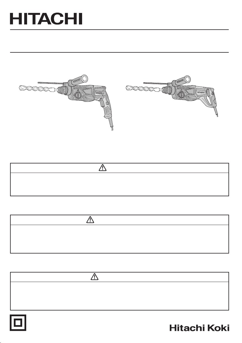
Rotary Hammer
Marteau rotatif
Martillo perforador
INSTRUCTION MANUAL AND SAFETY INSTRUCTIONS
WARNING
Improper and unsafe use of this power tool can result in death or serious bodily injury!
This manual contains important information about product safety. Please read and understand
this manual before operating the power tool. Please keep this manual available for others
before they use the power tool.
MODE D’EMPLOI ET INSTRUCTIONS DE SECURITE
AVERTISSEMENT
Une utilisation incorrecte et dangereuse de cet outil motorisé peut entraîner la mort ou de
sérieuses blessures corporelles!
Ce mode d’emploi contient d’importantes informations à propos de la sécurité de ce produit.
Prière de lire et de comprendre ce mode d’emploi avant d’utiliser l’outil motorisé. Garder ce
mode d’emploi à la disponibilité des autres utilisateurs avant qu’ils utilisent l’outil motorisé.
MANUAL DE INSTRUCCIONES E INSTRUCCIONES DE SEGURIDAD
ADVERTENCIA
¡La utilización inapropiada e insegura de esta herramienta eléctrica puede resultar en
lesiones serias o en la muerte!
Este manual contiene información importante sobre la seguridad del producto. Lea y
comprenda este manual antes de utilizar la herramienta eléctrica. Guarde este manual para
que puedan leerlo otras personas antes de que utilicen la herramienta eléctrica.
DOUBLE INSULATION
DOUBLE ISOLATION
AISLAMIENTO DOBLE
Page 2

English
CONTENTS
IMPORTANT SAFETY INFORMATION ......................3
MEANINGS OF SIGNAL WORDS ..............................3
SAFETY .........................................................................3
GENERAL POWER TOOL SAFETY WARNINGS .......3
SPECIFIC SAFETY RULES AND SYMBOLS ............. 4
DOUBLE INSULATION FOR SAFER OPERATION ....5
FUNCTIONAL DESCRIPTION ......................................7
NAME OF PARTS .......................................................7
SPECIFICATIONS ...................................................... 8
Page Page
ASSEMBLY AND OPERATION .....................................8
APPLICATIONS .......................................................... 8
PRIOR TO OPERATION ............................................. 8
HOW TO USE ............................................................. 9
HOW TO USE THE CORE BIT
(FOR LIGHT LOAD) ............................................. 12
MAINTENANCE AND INSPECTION ..........................13
ACCESSORIES ...........................................................14
STANDARD ACCESSORIES....................................14
OPTIONAL ACCESSORIES .....................................14
PARTS LIST .................................................................49
Français
TABLE DES MATIÈRES
Page Page
INFORMATIONS IMPORTANTES DE SÉCURITÉ ...17
SIGNIFICATION DES MOTS D’AVERTISSEMENT ...17
SECURITE ..................................................................17
AVERTISSEMENTS DE SÉCURITÉ GÉNÉRAUX
CONCERNANT LES OUTILS ÉLECTRIQUES ...17
REGLES DE SECURITE SPECIFIQUES ET
SYMBOLES ........................................................19
DOUBLE ISOLATION POUR UN
FONCTIONNEMENT PLUS SUR ........................20
DESCRIPTION FONCTIONNELLE ............................21
NOM DES PARTIES ................................................21
SPECIFICATIONS ...................................................22
Español
Página Página
INFORMACIÓN IMPORTANTE SOBRE
SEGURIDAD ....................................................... 33
SIGNIFICADO DE LAS PALABRAS DE
SEÑALIZACIÓN ..................................................33
SEGURIDAD ...............................................................33
ADVERTENCIAS DE SEGURIDAD GENERAL DE
LA HERRAMIENTA ELÉCTRICA .........................33
NORMAS Y SÍMBOLOS ESPECÍFICOS DE
SEGURIDAD ....................................................... 35
AISLAMIENTO DOBLE PARA OFRECER UNA
OPERACIÓN MÁS SEGURA .............................. 36
DESCRIPCIÓN FUNCIONAL .....................................37
NOMENCLATURA ..................................................37
ESPECIFICACIONES ..............................................38
ASSEMBLAGE ET FONCTIONNEMENT ...................22
APPLICATIONS ....................................................... 22
AVANT L’UTILISATION ............................................22
UTILISATION ........................................................... 23
CO MMENT UTILISER LA COURONNE
(POUR UNE CHARGE LEGERE) .......................26
ENTRETIEN ET INSPECTION ....................................28
ACCESSOIRES ...........................................................29
ACCESSOIRES STANDARD ................................... 29
ACCESSOIRES SUR OPTION ................................29
LISTA DES PIÈCES .................................................... 49
ÍNDICE
MONTAJE Y OPERACIÓN .......................................... 38
APLICACIONES ......................................................38
ANTES DE LA OPERACIÓN ...................................38
COMO SE USA .......................................................40
MODO DE USAR LA BARRENA TUBULAR
(PARA CARGAS LIGERAS) ...............................42
MANTENIMIENTO E INSPECCIÓN ...........................44
ACCESORIOS .............................................................45
ACCESORIOS ESTÁNDAR ....................................45
ACCESORIOS OPCIONALES .................................45
LISTA DE PIEZAS .......................................................49
Page 3

English
IMPORTANT SAFETY INFORMATION
Read and understand all of the safety precautions, warnings and operating instructions in the Instruction Manual before
operating or maintaining this power tool.
Most accidents that result from power tool operation and maintenance are caused by the failure to observe basic safety
rules or precautions. An accident can often be avoided by recognizing a potentially hazardous situation before it occurs,
and by observing appropriate safety procedures.
Basic safety precautions are outlined in the “SAFETY” section of this Instruction Manual and in the sections which contain
the operation and maintenance instructions.
Hazards that must be avoided to prevent bodily injury or machine damage are identifi ed by WARNINGS on the power tool
and in this Instruction Manual.
NEVER use this power tool in a manner that has not been specifi cally recommended by HITACHI.
MEANINGS OF SIGNAL WORDS
WARNING indicates a potentially hazardous situations which, if ignored, could result in death or serious injury.
CAUTION indicates a potentially hazardous situations which, if not avoided, may result in minor or moderate injury, or
may cause machine damage.
NOTE emphasizes essential information.
SAFETY
GENERAL POWER TOOL SAFETY WARNINGS
WARNING
Read all safety warnings and all instructions.
Failure to follow the warnings and instructions may result in electric shock, fi re and/or serious injury.
Save all warnings and instructions for future reference.
The term “power tool” in the warnings refers to your mains-operated (corded) power tool or battery-operated
(cordless) power tool.
1) Work area safety
a) Keep work area clean and well lit.
Cluttered or dark areas invite accidents.
b) Do not operate power tools in explosive
atmospheres, such as in the presence of
fl ammable liquids, gases or dust.
Power tools create sparks which may ignite the
dust or fumes.
c) Keep children and bystanders away while
operating a power tool.
Distractions can cause you to lose control.
2) Electrical safety
a) Power tool plugs must match the outlet.
Never modify the plug in any way.
Do not use any adapter plugs with earthed
(grounded) power tools.
Unmodified plugs and matching outlets will
reduce risk of electric shock.
b) Avoid body contact with earthed or grounded
surfaces such as pipes, radiators, ranges and
refrigerators.
There is an increased risk of electric shock if
your body is earthed or grounded.
c) Do not expose power tools to rain or wet
conditions.
Water entering a power tool will increase the
risk of electric shock.
d) Do not abuse the cord. Never use the cord for
carrying, pulling or unplugging the power tool.
Keep cord away from heat, oil, sharp edges
or moving parts.
Damaged or entangled cords increase the risk
of electric shock.
e) When operating a power tool outdoors, use
an extension cord suitable for outdoor use.
Use of a cord suitable for outdoor use reduces
the risk of electric shock.
f) If operating a power tool in a damp location
is unavoidable, use a residual current device
(RCD) protected supply.
Use of an RCD reduces the risk of electric shock.
3) Personal safety
a) Stay alert, watch what you are doing and use
common sense when operating a power tool.
Do not use a power tool while you are tired
or under the infl uence of drugs, alcohol or
medication.
3
Page 4

English
A moment of inattention while operating power
tools may result in serious personal injury.
b) Use personal protective equipment. Always
wear eye protection.
Protective equipment such as dust mask,
non-skid safety shoes, hard hat, or hearing
protection used for appropriate conditions will
reduce personal injuries.
c) Prevent unintentional starting. Ensure the
switch is in the off -position before connecting
to power source and/or battery pack, picking
up or carrying the tool.
Carrying power tools with your finger on the
switch or energising power tools that have the
switch on invites accidents.
d) Remove any adjusting key or wrench before
turning the power tool on.
A wrench or a key left attached to a rotating part
of the power tool may result in personal injury.
e) Do not overreach. Keep proper footing and
balance at all times.
This enables better control of the power tool in
unexpected situations.
f) Dress properly. Do not wear loose clothing
or jewellery. Keep your hair, clothing and
gloves away from moving parts.
Loose clothes, jewellery or long hair can be
caught in moving parts.
g) If devices are provided for the connection
of dust extraction and collection facilities,
ensure these are connected and properly
used.
Use of dust collection can reduce dust-related
hazards.
4) Power tool use and care
a) Do not force the power tool. Use the correct
power tool for your application.
The correct power tool will do the job better and
safer at the rate for which it was designed.
b) Do not use the power tool if the switch does
not turn it on and off .
Any power tool that cannot be controlled with
the switch is dangerous and must be repaired.
c) Disconnect the plug from the power source
and/or the battery pack from the power tool
before making any adjustments, changing
accessories, or storing power tools.
Such preventive safety measures reduce the
risk of starting the power tool accidentally.
d) Store idle power tools out of the reach of
children and do not allow persons unfamiliar
with the power tool or these instructions to
operate the power tool.
Power tools are dangerous in the hands of
untrained users.
e) Maintain power tools. Check for misalignment
or binding of moving parts, breakage of parts
and any other condition that may aff ect the
power tool’s operation.
If damaged, have the power tool repaired
before use.
Many accidents are caused by poorly maintained
power tools.
f) Keep cutting tools sharp and clean.
Properly maintained cutting tools with sharp
cutting edges are less likely to bind and are
easier to control.
g) Use the power tool, accessories and tool bits
etc. in accordance with these instructions,
taking into account the working conditions
and the work to be performed.
Use of the power tool for operations different
from those intended could result in a hazardous
situation.
5) Service
a) Have your power tool serviced by a qualifi ed
repair person using only identical replacement
parts.
This will ensure that the safety of the power tool
is maintained.
SPECIFIC SAFETY RULES AND SYMBOLS
1. Wear ear protectors.
Exposure to noise can cause hearing
loss.
2. Use auxiliary handles, if supplied with the tool.
Loss of control can cause personal injury.
3. Hold power tools by insulated gripping surfaces
when performing an operation where the cutting
tool may contact hidden wiring or its own cord.
Cutting accessory contacting a “live” wire may make
exposed metal parts of the power tool “live” and could
give the operator an electric shock.
4. NEVER touch the tool bit with bare hands after
operation.
5. NEVER wear gloves made from materials likely to roll
up such as cotton, wool, cloth or string, etc.
6. ALWAYS attach the side handle and securely grip the
Rotary Hammer.
7. NEVER touch moving parts.
NEVER place your hands, fi ngers or other body parts
near the tool’s moving parts.
8. Never operate without all guards in place.
NEVER operate this tool without all guards or safety
features in place and in proper working order. If
maintenance or servicing requires the removal of a
guard or safety feature, be sure to replace the guard or
safety feature before resuming operation of the tool.
4
Page 5
English
9. Use right tool.
Don’t force small tool or attachment to do the job of a
heavy-duty tool.
Don’t use tool for purpose not intended —for
example— don’t use circular saw for cutting tree limbs
or logs.
10. NEVER use a power tool for applications other
than those specifi ed.
NEVER use a power tool for applications other than
those specifi ed in the Instruction Manual.
11. Handle tool correctly.
Operate the tool according to the instructions provided
herein. Do not drop or throw the tool.
NEVER allow the tool to be operated by children,
individuals unfamiliar with its operation or unauthorized
personnel.
12. Keep all screws, bolts and covers tightly in place.
Keep all screws, bolts, and plates tightly mounted.
Check their condition periodically.
13. Do not use power tools if the plastic housing or
handle is cracked.
Cracks in the tool’s housing or handle can lead to
electric shock. Such tools should not be used until
repaired.
14. Blades and accessories must be securely
mounted to the tool.
Prevent potential injuries to youself or others. Blades,
cutting implements and accessories which have been
mounted to the tool should be secure and tight.
15. Keep motor air vent clean.
The tool’s motor air vent must be kept clean so that
air can freely fl ow at all times. Check for dust build-up
frequently.
16. Operate power tools at the rated voltage.
Operate the power tool at voltages specifi ed on its
nameplate.
If using the power tool at a higher voltage than the rated
voltage, it will result in abnormally fast motor revolution
and may damage the unit and the motor may burn out.
17. NEVER use a tool which is defective or operating
abnormally.
If the tool appears to be operating unusually, making
strange noises, or otherwise appears defective, stop
using it immediately and arrange for repairs by a
Hitachi authorized service center.
18. NEVER leave tool running unattended. Turn power
off .
Don’t leave tool until it comes to a complete stop.
19. Carefully handle power tools.
Should a power tool be dropped or struck against hard
materials inadvertently, it may be deformed, cracked,
or damaged.
20. Do not wipe plastic parts with solvent.
Solvents such as gasoline, thinner benzine, carbon
tetrachloride, and alcohol may damage and crack
plastic parts. Do not wipe them with such solvents.
Wipe plastic parts with a soft cloth lightly dampened
with soapy water and dry thoroughly.
21. ALWAYS wear eye protection that meets the
requirement of the latest revision of ANSI
Standard Z87.1.
22. ALWAYS be careful with buried object such as an
underground wiring.
Touching live wiring or electric cable with this tool may
result in electric shock.
Confi rm before use whether hidden objects are
present, such as electric cables within the wall, fl oor or
ceiling.
23. Defi nitions for symbols used on this tool
V....................volts
Hz .................hertz
A ...................amperes
n
..................no load speed
o
W ..................watt
..................Class II Construction
---/min ...........revolutions per minute
.................. Alternati ng cu rrent
DOUBLE INSULATION FOR SAFER
OPERATION
To ensure safer operation of this power tool, HITACHI has
adopted a double insulation design. “Double insulation”
means that two physically separated insulation systems
have been used to insulate the electrically conductive
materials connected to the power supply from the outer
frame handled by the operator. Therefore, either the
symbol “ ” or the words “Double insulation” appear on
the power tool or on the nameplate.
Although this system has no external grounding, you must
still follow the normal electrical safety precautions given in
this Instruction Manual, including not using the power tool
in wet environments.
To keep the double insulation system eff ective, follow
these precautions:
○
Only HITACHI AUTHORIZED SERVICE CENTER
should disassemble or assemble this power tool, and
only genuine HITACHI replacement parts should be
installed.
○
Clean the exterior of the power tool only with a soft cloth
moistened with soapy water, and dry thoroughly.
Never use solvents, gasoline or thinners on plastic
components; otherwise the plastic may dissolve.
5
Page 6

English
SAVE THESE INSTRUCTIONS
AND
MAKE THEM AVAILABLE TO OTHER USERS
AND
OWNERS OF THIS TOOL!
6
Page 7
English
FUNCTIONAL DESCRIPTION
NOTE
The information contained in this Instruction Manual is designed to assist you in the safe operation and maintenance
of the power tool.
NEVER operate, or attempt any maintenance on the tool unless you have fi rst read and understood all safety instructions
contained in this manual.
Some illustrations in this Instruction Manual may show details or attachments that diff er from those on your own power
tool.
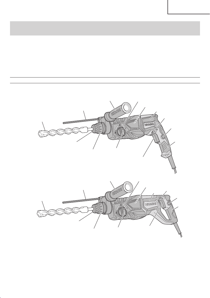
NAME OF PARTS
[DH26PC]
Drill bit
[DH26PF / DH28PFY]
Drill bit
Depth gauge
Front cap
Depth gauge
Front cap
Grip
Grip
Side handle
Change lever
Side handle
Change lever
Push button
Nameplate
Switch trigger
Push button
Nameplate
Switch trigger
Housing
Housing
Push button
Stopper
Handle
Push button
Stopper
Handle
Fig. 1
7
Page 8
English
SPECIFICATIONS
Model Name DH26PC DH26PF DH28PFY
Type of Handle Gun-type Handle D-type Handle
Motor Single-Phase, Series Commutator Motor
Power Source Single-Phase, 120 V 60 Hz
Current 7.3 A 7.5 A 8.0 A
Concrete 1/8" – 1" (3.4 mm – 26 mm)
Capacity
No-Load Speed 0 – 1,100 /min.
Full-load Blow 0 – 4,300 /min.
Weight 6.2 lbs (2.8 kg) 6.7 lbs (3.0 kg) 6.9 lbs (3.1 kg)
Steel 1/2" (13 mm) 1/2" (13 mm)
Wood 1-1/4" (32 mm) 1-1/4" (32 mm)
1/8" – 1-1/8" (3.4 mm – 28 mm)
ASSEMBLY AND OPERATION
APPLICATIONS
Rotation and hammering function
○
Drilling anchor holes
○
Drilling holes in concrete
○
Drilling holes in tile
Rotation only function
○
Drilling in steel or wood (with optional accessories).
○
Tightening machine screws, wood screws (with
optional accessories).
Hammering only function
○
Light-duty chiselling of concrete, groove digging
and edging.
PRIOR TO OPERATION
1. Power source
Ensure that the power source to be utilized conforms
to the power source requirements specifi ed on the
product nameplate.
2. Power switch
Ensure that the switch is in the OFF position. If the
plug is connected to a receptacle while the switch is
in the ON position, the power tool will start operating
immediately and can cause serious injury.
3. Extension cord
When the work area is far away from the power source,
use an extension cord of suffi cient thickness and rated
capacity. The extension cord should be kept as short
as practicable.
WARNING
Damaged cord must be replaced
or repaired.
4. Check the receptacle
If the receptacle only loosely accepts the plug, the
receptacle must be repaired. Contact a licensed
electrician to make appropriate repairs.
If such a faulty receptacle is used, it may cause
overheating, resulting in a serious hazard.
5. Confi rming condition of the environment
Confi rm that the work site is placed under appropriate
conditions conforming to prescribed precautions.
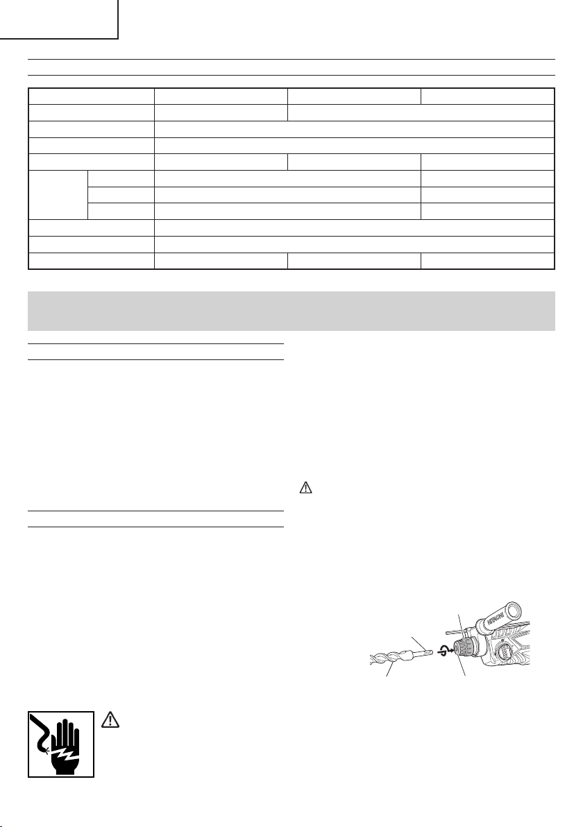
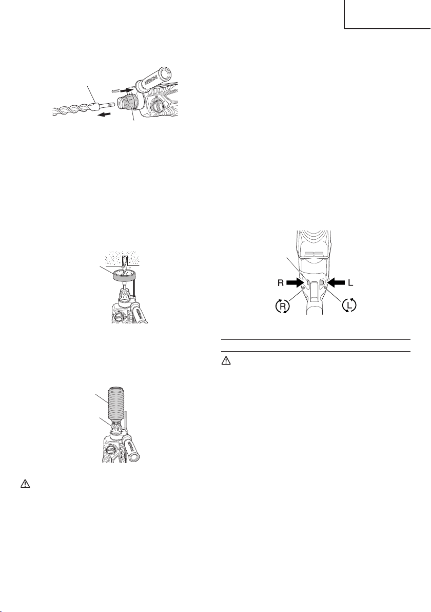
6. Mounting the drill bit (Fig. 2)
CAUTION
●
Be sure to switch power OFF and disconnect the
plug from the receptacle.
●
For tools such as a drill bit and a bull point, use
only Hitachi genuine parts.
(1) Clean the shank portion of the drill bit.
(2) Insert the drill bit in a twisting manner into the tool holder
until it latches 0itself. (Fig. 2)
Grip
Part of SDS-plus shank
Drill bit
(3) Check the latching by pulling on the drill bit.
Front cap
Fig. 2
8
Page 9
English
(4) To remove the drill bit, fully pull the grip in the direction
of the arrow and pull out the drill bit. (Fig. 3)
dust collector (B) attached to a drill bit that has
more than 7-15/32" (190 mm) of overall length,
dust collector (B) cannot touch the concrete
Drill bit
surface and will rotate. Therefore please use
dust collector (B) by attaching to drill bits which
have 6-17/32" (166 mm), 6-19/64" (160 mm) and
4-21/64" (110 mm) overall length.)
○
Dump particles after every two or three holes when
Grip
Fig. 3
7. Installation of dust cup or dust collector (B) (Optional
accessories) (Fig. 4, Fig. 5)
When using a rotary hammer for upward drilling
operations attach a dust cup or dust collector (B) to
collect dust or particles for easy operation.
○
Installing the dust cup
Use the dust cup by attaching to the drill bit a shown in
Fig. 4.
drilling.
○
Please replace the drill bit after removing dust
collector (B).
8. Selecting the driver bit
Screw heads or bits will be damaged unless a bit
appropriate for the screw diameter is employed to drive
in the screws.
9. Confi rm the direction of bit rotation (Fig. 6)
The bit rotates clockwise (viewed from the rear side) by
pushing the R-side of the push button. The L-side of the
push button is pushed to turn the bit counterclockwise.
When using a bit which has big diameter, enlarge the
center hole of the dust cup with this rotary hammer.
Dust cup
Fig. 4
○
Installing dust collector (B)
When using dust collector (B), insert dust collector (B)
from the tip of the bit by aligning it to the groove on the
grip (Fig. 5)
Dust collector (B)
HOW TO USE
CAUTION
To prevent accidents, make sure to turn the switch
off and disconnect the plug from the receptacle
when the drill bits and other various parts are
installed or removed. The power switch should
also be turned off during a work break and after
Grip
work.
1. Switch operation
○
The rotation speed of the drill bit can be controlled
steplessly by varying the amount that the trigger
switch is pulled. Speed is low when the trigger switch
Fig. 5
CAUTION
○
The dust cup and dust collector (B) are for
exclusive use of concrete drilling work. Do not
use them for wood or metal drilling work.
○
Insert dust collector (B) completely into the chuck
part of the main unit.
○
When turning the rotary hammer on while dust
collector (B) is detached from a concrete surface,
dust collector (B) will rotate together with the drill
is pulled slightly and increases as the switch is pulled
more. To turn the switch OFF, release the trigger
switch to its original position. However, the switch
trigger can only be pulled in halfway during reverse and
rotates at half the speed of forward operation.
○
Pulling the trigger and pushing the stopper, it keeps
the switched-on condition which is convenient for
continuous running. When switching off , the stopper
can be disconnected by pulling the trigger again. The
switch stopper is unusable during reverse.
bit. Make sure to turn on the switch after pressing
dust cup on the concrete surface. (When using
Push
button
Fig. 6
9
Page 10
English
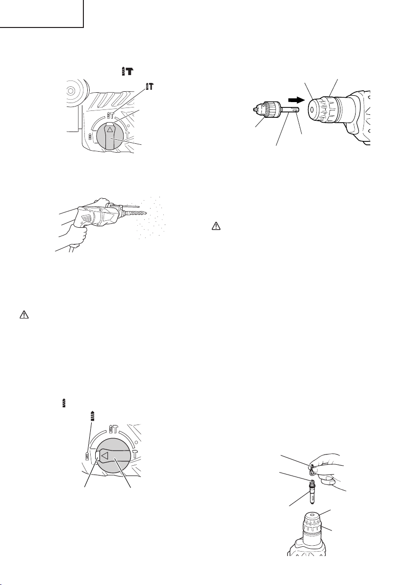
2. Rotation + Hammering
To drill a wood or metal material using the separately
This rotary hammer can be set to rotation and
hammering mode by pressing the push button and
turning the change lever to mark. (Fig. 7)
Push button
Change lever
Fig. 7
(1) Mount the drill bit.
(2) Pull the trigger switch after applying the drill bit tip to
the drilling position (Fig. 8)
(1) Attach the drill chuck to the chuck adaptor.
(2) The part of the SDS-plus shank is the same as the drill
CAUTION
○
Application of force more than necessary will not
Fig. 8
○
(3) Pushing the rotary hammer forcibly is not necessary
Drill bit may snap off while withdrawing the rotary
at all. Pushing slightly so that drill dust comes out
gradually is just suffi cient.
○
Do not attempt to drill anchor holes or holes in
CAUTION
○
When the drill bit touches an iron reinforcing
Do not attempt to use the rotary hammer in the
rod, the bit will stop immediately and the rotary
hammer will react to revolve. Therefore please grip
the side handle and handle tightly as shown in Fig.
8.
sold drill chuck and chuck adaptor, proceed as follows.
Installing drill chuck and chuck adaptor (Fig. 10):
Front cap
Drill chuck
Chuck adaptor
Part of SDS-plus
shank
Grip
Fig. 10
bit. Therefore, refer to the item of “Mounting the drill bit”
for attaching it.
only reducing drilling effi ciency at all, but will
deteriorate the tip edge of the drill bit and reduce
the service life of the rotary hammer in addition.
hammer from the drilled hole. For withdrawing, it
is important to use a pushing motion.
concrete with the main unit in the rotation only
function.
rotation and striking function with the drill chuck
and chuck adaptor attached. This would seriously
shorten the service life of every components of the
machine.
3. Rotation only
This rotary hammer can be set to rotation only mode
by pressing the push button and turning the change
lever to mark. (Fig. 9)
Push button
Change lever
Fig. 9
10
4. When driving machine screws (Fig. 11)
First, insert the bit into the socket in the end of chuck
adaptor (D).
Next, mount chuck adaptor (D) on the main unit using
procedures described in 6 (1), (2), (3), of "PRIOR TO
OPERATION", put the tip of the bit in the slots in the
head of the screw, grasp the main unit and tighten the
screw.
Bit
Socket
Chuck adaptor (D)
Front cap
Grip
Fig. 11
Page 11
CAUTION
○
Exercise care not to excessively prolong driving
time, otherwise, the screws may be damaged by
excessive force.
○
Apply the rotary hammer perpendicularly to the
screw head when driving a screw; otherwise, the
screw head or bit will be damaged, or driving force
will not be fully transferred to the screw.
○
Do not attempt to use the rotary hammer in the
rotation and striking function with chuck adaptor
(D) and bit attached.
5. When driving wood screws (Fig. 11)
(1) Selecting a suitable driver bit
Employ phillips screws, if possible, since the driver bit
easily slips off the heads of slotted-head screws.
(2) Driving in wood screws
○
Prior to driving in wood screws, make pilot holes
suitable for them in the wooden board. Apply the bit to
the screw head grooves and gently drive the screws
into the holes.
○
After rotating the rotary hammer at low speed for a
while until a wood screw in partly driven into the wood,
squeeze the trigger more strongly to obtain the optimum
driving force.
CAUTION
Exercise care in preparing a pilot hole suitable for
the wood screw taking the hardness of the wood
into consideration. Should the hole be excessively
small or shallow, requiring much power to drive
the screw into it, the thread of the wood screw may
sometimes be damaged.
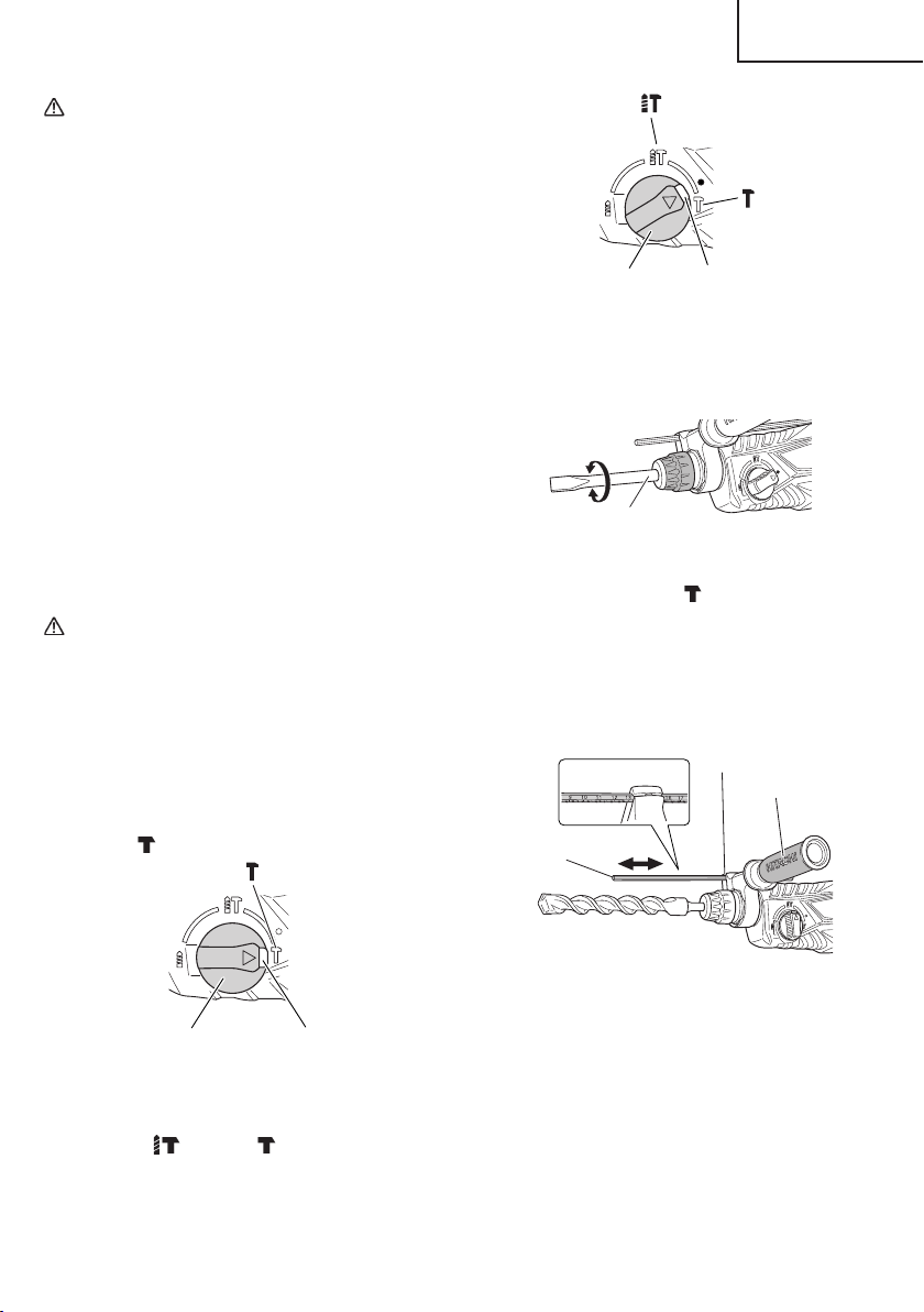
6. Hammering only
This rotary hammer can be set to hammering only mode
by pressing the push button and turning the change
lever to mark. (Fig. 12)
English
Change lever
The rotation is released. Turn the tool bit and adjust
the cold chisel or other tool bit to the desired position.
(Fig. 14)
Tool bit
(3) Turn the change lever to
Then, the tool bit is locked.
7. Using depth gauge (Fig. 15)
(1) Loosen the knob on the side handle, and insert the
depth gauge into the mounting hole on the side handle.
(2) Adjust the depth gauge position according to the depth
of the hole and tighten the knob bolt securely.
Depth gauge
Push button
Fig. 13
Fig. 14
mark. (Fig. 12)
Mounting hole
Side handle
Change lever
Push button
Fig. 12
(1) Mount the bull point, cold chisel, or other tool bit.
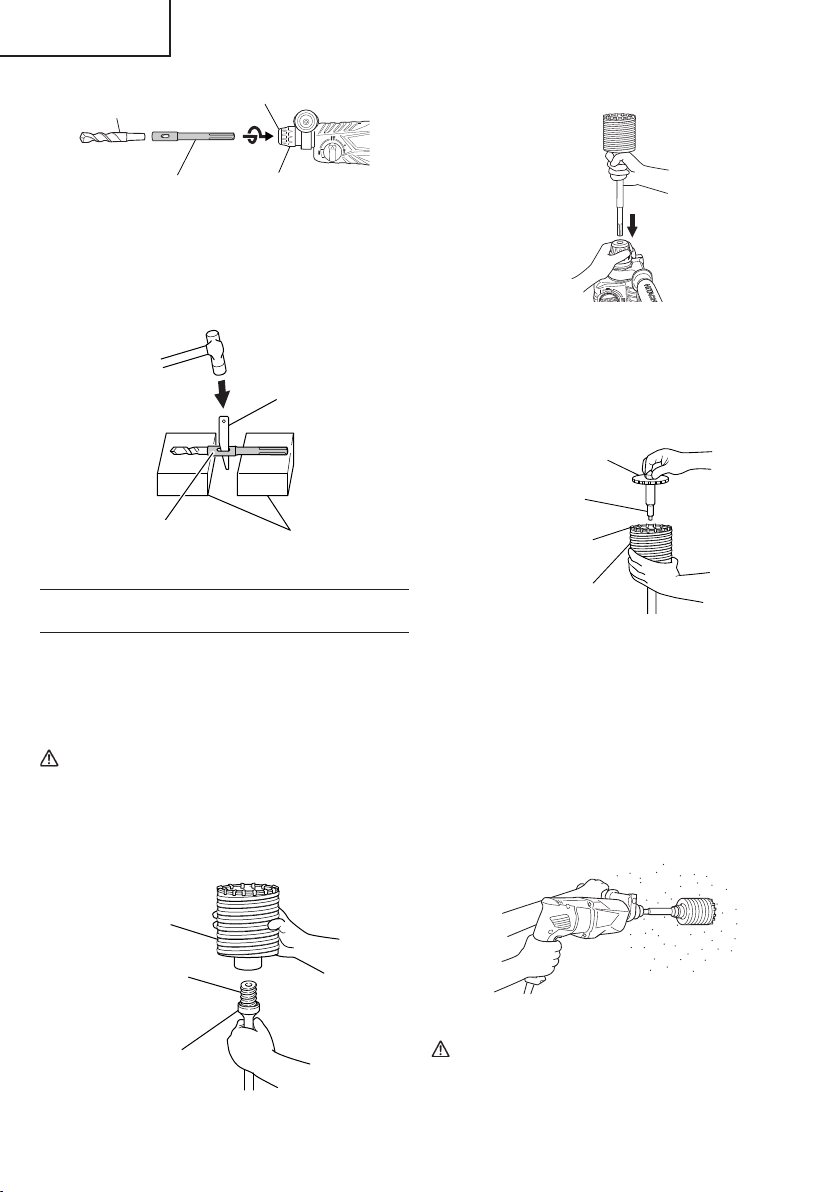
8. How to use the drill bit (taper shank) and the taper
(1) Mount the taper shank adaptor to the rotary hammer.
(2) Mount the drill bit (taper shank) to the taper shank
(2) Press the push button and set the change lever to
middle of
mark and mark. (Fig. 13)
(3) Turn the switch ON, and drill a hole in prescribed depth.
Fig. 15
shank adaptor.
(Fig. 16)
adaptor. (Fig. 16)
11
Page 12
English
Drill bit
Taper shank
Front cap
Grip
(2) Mount the core bit shank to the rotary hammer. (Fig. 19)
adaptor
Fig. 16
(4) To remove the drill bit (taper shank), insert the cotter
into the slot of the taper shank adaptor and strike the
head of the cotter with a hammer supporting on the
rests. (Fig. 17)
(3) Insert the center pin into the guide plate until it stops.
(4) Engage the guide plate with the core bit, and turn the
Taper shank
adaptor
Cotter
Rests
Fig. 17
HOW TO USE THE CORE BIT (FOR LIGHT
LOAD)
When boring penetrating large hole use the core bit (for
light load). At that time use with the center pin and the core
bit shank provided as optional accessories.
1. Mounting
CAUTION
2. How to bore (Fig. 21)
(1) Connect the plug to the receptacle.
(2) A spring is installed in the center pin. Push it lightly to
(3) When boring about 3/16" (5 mm) in depth the position
Be sure to switch power OFF and disconnect the
plug from the receptacle.
(4) Application of excessive force will not only expedite
(1) Mount the core bit to the core bit shank. (Fig. 18)
Lubricate the thread of the core bit shank to facilitate
disassembly.
Fig. 19
guide plate to left or right so that it does not fall even if
it faces downward. (Fig. 20)
Guide plate
Center pin
Core bit tip
Core bit
Fig. 20
the wall or the fl oor straight. Connect all over the surface
of the core bit tip and start operating.
of the hole will establish. Bore after that removing the
center pin and the guide plate from core bit.
the work, but will deteriorate the tip edge of the drill bit,
resulting in reduced service life of the rotary hammer.
Core bit
Thread
Fig. 21
Core bit shank
CAUTION
When removing the center pin and the guide plate,
turn OFF the switch and disconnect the plug form
Fig. 18
12
the receptacle.
Page 13
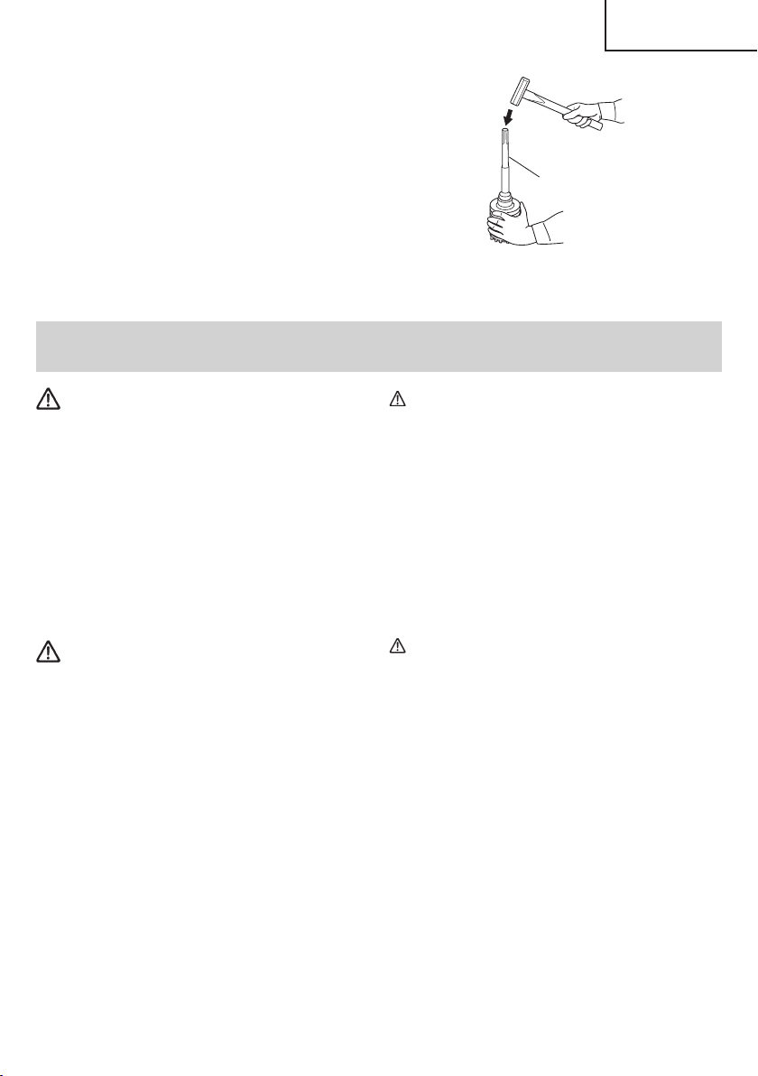
3. Dismounting. (Fig. 22)
Remove the core bit shank from the rotary hammer
and strike the head of the core bit shank strongly two
or three times with the manual hammer holding the
core bit, then the thread becomes loose and the core
bit can be removed.
MAINTENANCE AND INSPECTION
English
Core bit shank
Fig. 22
WARNING
Be sure to switch power OFF and disconnect the
plug from the receptacle during maintenance and
inspection.
1. Inspecting the drill bits
Since use of a dull tool will cause motor malfunctioning
and degraded effi ciency, replace the drill bit with a new
one or resharpening without delay when abrasion is
noted.
2. Inspecting the screws
Regularly inspect all screws and ensure that they
are properly tightened. Should any of the screws be
loosened, retighten them immediately.
WARNING
Using this rotary hammer with loosen screws is
extremely dangerous.
3. Maintenance of the motor
The motor unit winding is the very “heart” of the power
tool. Exercise due care to ensure the winding does not
become damaged and/or wet with oil or water.
4. Inspecting the carbon brushes
For your continued safety and electrical shock
protection, carbon brush inspection and replacement
on this tool should ONLY be performed by a Hitachi
Authorized Service Center.
5. How to replace grease
Low viscosity grease is applied to this rotary hammer
so that it can be used for a long period without
replacing the grease. Replace the grease whenever you
change the carbon brush to maintain the service life.
Please contact the nearest service center for grease
replacement when any grease is leaking from loosened
screw. Further use of the rotary hammer despite the
grease shortage causes seizure to reduce the service
life.
CAUTION
A specific grease is used with this machine,
therefore, the normal performance of the machine
may be badly aff ected by use of other grease.
Please be sure to let one of our service agents
undertake replacement of the grease.
6. Service and repairs
All quality power tools will eventually require servicing
or replacement of parts because of wear from normal
use. To assure that only authorized replacement parts
will be used, all service and repairs must be performed
by a Hitachi Authorized Service Center, ONLY.
7. Service parts list
CAUTION
Repair, modifi cation and inspection of Hitachi
Power Tools must be carried out by a Hitachi
Authorized Service Center.
This Parts List will be helpful if presented with
the tool to the Hitachi Authorized Service Center
when requesting repair or other maintenance. In
the operation and maintenance of power tools,
the safety regulations and standards prescribed
in each country must be observed.
MODIFICATIONS
Hitachi Power Tools are constantly being improved
and modifi ed to incorporate the latest technological
advancements.
Accordingly, some parts may be changed without prior
notice.
13
Page 14
English
ACCESSORIES
WARNING
ALWAYS use Only authorized HITACHI replacement parts and accessories. Never use replacement parts or
accessories which are not intended for use with this tool. Contact HITACHI if you are not sure whether it is
safe to use a particular replacement part or accessory with your tool.
The use of any other attachment or accessory can be dangerous and could cause injury or mechanical
damage.
NOTE
Accessories are subject to change without any obligation on the part of the HITACHI.
STANDARD ACCESSORIES
(1) Plastic Case (Code No. 335257) (for DH26PC) .........................................................................................................1
(2) Side Handle (Code No. 335273) ...............................................................................................................................1
(3) Depth Gauge (Code No. 310331) ..............................................................................................................................1
OPTIONAL ACCESSORIES...sold separately
(Code No. 370155) (for DH26PF, DH28PFY) .......................................................................................1
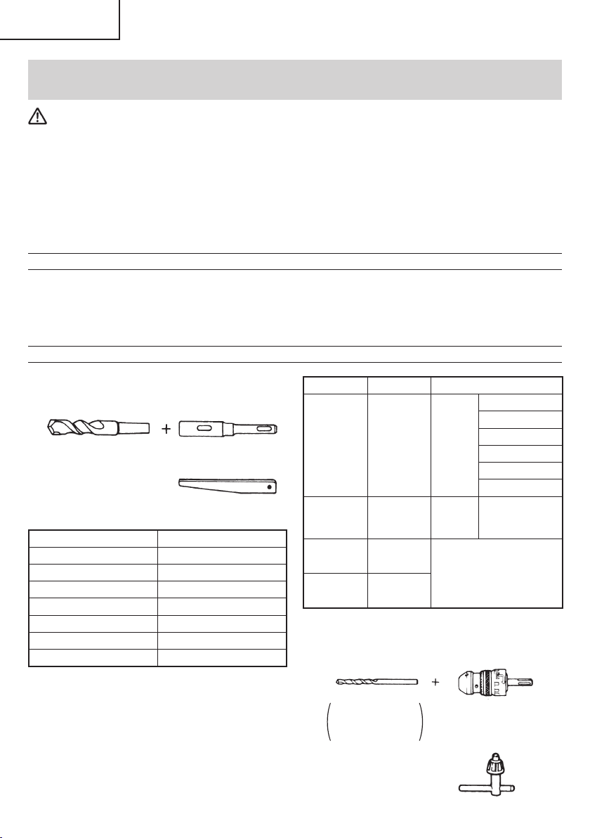
1. Drilling anchor holes (Rotation + Hammering)
○
Drill Bit (Taper shank) and taper shank adaptor
(1) Drill Bit (Taper Shank) (2) Taper Shank Adaptor
External dia. Code No.
7/16" (11 mm) 944460
1/2" (12.3 mm) 944461
1/2" (12.7 mm) 993038
9/16" (14.3 mm) 944462
9/16" (14.5 mm) 944500
11/16" (17.5 mm) 944463
7/8" (21.5 mm) 944464
(SDS-plus shank)
Cotter (Code No. 944477)
Taper mode Code No. Applicable drill bit
7/16" (11 mm)
Morse taper
(No. 1)
Morse taper
(No. 2)
A-taper 303619
B-taper 303620
○
1/2" (13 mm) Hammer Drill chuck and Chuck wrench
For drilling operations when using a straight shank bit
for impact drilling with a rotary hammer
Impact Drill
Application
Straight shank Bit
3 0 3 6 1 7
303618
Drill bit
(Taper
shank)
Drill bit
(Taper
shank)
Taper shank adaptor
formed A-taper or B-taper
is provided as an optional
accessory, but drill bit for it
is not provided.
1/2" (13 mm) Hammer Drill
Chuck (SDS-plus shank)
(includes Chuck wrench)
1/2" (12.3 mm)
1/2" (12.7 mm)
9/16" (14.3 mm)
9/16" (14.5 mm)
11/16" (17.5 mm)
7/8" (21.5 mm)
14
Chuck wrench
Page 15
English
Name Code No.
1/2" (13 mm) Hammer Drill Chuck 303332
Chuck wrench 303334
Rubber Cap 303335
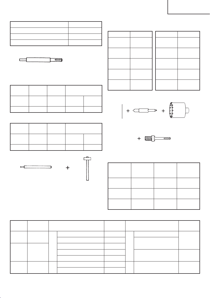
2. Knock-in anchor (Hammering only)
Anchor Setter (for anchor setting)
(SDS-plus shank)
<Outer wedge type with the female screw>
Anchor
size
Overall
Length
W 1/4"
(6.3 mm)
10-1/4"
(260 mm)
W 5/16"
(8 mm)
10-1/4"
(260 mm)
(9.5 mm)
6-1/4"
(160 mm)
W 3/8"
10-1/4"
(260 mm)
Code No. 302976 302975 303621 302974
<Inner wedge type with the headless screw>
Anchor
size
Overall
Length
W 1/4"
(6.3 mm)
10-1/4"
(260 mm)
W 5/16"
(8 mm)
10-1/4"
(260 mm)
(9.5 mm)
6-1/4"
(160 mm)
W 3/8"
10-1/4"
(260 mm)
Code No. 302979 302978 303622 302977
Anchor setting adaptor
(for manual hammer)
<Outer wedge type with
the female screw>
Anchor size Code No.
W1/4"
(6.3 mm)
W5/16"
(8 mm)
W3/8"
(9.5 mm)
W1/2"
(12.7 mm)
W5/8"
(15.9 mm)
971794
971795
971796
971797
971798
<Inner wedge type with
the headless screw>
Anchor size Code No.
W1/4"
(6.3 mm)
W5/16"
(8 mm)
W3/8"
(9.5 mm)
W1/2"
(12.7 mm)
W5/8"
(15.9 mm)
971799
971800
971801
971802
971803
3. Large hole boring (Rotation + Hammering)
Guide
Center pin Core Bit
Plate
Core bit Shank
(SDS-plus shank)
Guide plate
Core bit
(outer
diameter)
1-1/4"
(32 mm)
1-3/8"
(35 mm)
1-1/2"
(38 mm)
Code No.
982686
982687
982688
Core bit
(outer
diameter)
1-3/4"
(45 mm)
2"
(50 mm)
Code No.
982689
982690
Center
Code No. Core bit (outer diameter) Code No. Core bit shank Code No.
pin
––
(A)
(A) 982684
(B) 982685 (B)
1"(25 mm) 982672
1-1/4" (32 mm) 982674
1-3/8" (35 mm) 982675
1-1/2" (38 mm) 982676
1-3/4" (45 mm) 982677
2" (50 mm) 982678
(A)
(B)
Overall length
4 -1 / 8 "
(105 mm)
12"
(300 mm)
12"
(300 mm)
303625 1 - 1 / 8 " ( 2 9 m m ) 9 8 2 6 7 3
303626
303627
15
Page 16
English
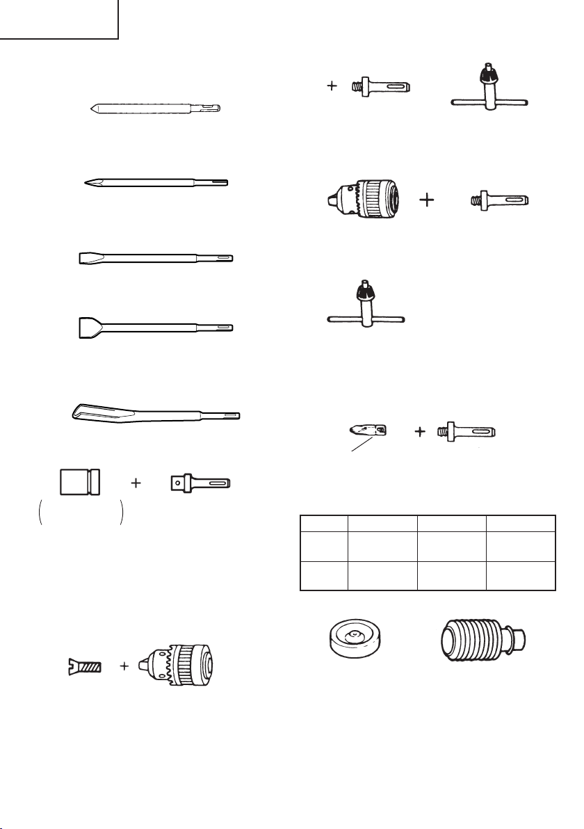
4. Demolishing operation (Hammering only)
○
Bull point (Round type) (SDS-plus shank)
Code No. 303046
○
Bull point (Square type) (SDS-plus shank)
Code No. 316656
5. Groove digging and edging (Hammering only)
○
Cold chisel (SDS-plus shank)
Code No. 316657
○
Cutter (SDS-plus shank)
Code No. 316658
6. Grooving (Hammering only)
Grooving chisel (SDS-plus shank)
Code No. 316659
Chuck adaptor G
(SDS-plus shank)
Code No. 303623
Chuck wrench
9. Drilling holes (Rotation only)
Drill chuck (13VLD–D)
(includes chuck wrench)
Code No. 321813
Chuck wrench
○
1/2" (13 mm) drill chuck ass’y (includes chuck wrench)
Chuck adaptor (D)
(SDS-plus shank)
Code No. 303624
and chuck (for drilling into steel or wood).
10. Driving Screws (Rotation only)
7. Bolt placing operation with Chemical Anchor.
(Rotation + Hammering)
Standard socket
on the market
(SDS-plus shank)
○
1/2" (12.7 mm)
Chemical Anchor Adapter
(Code No.303044)
○
3/4" (19 mm)
Chemical Anchor Adapter
(Code No. 303045)
8. Drilling holes and driving screws (Rotation only)
○
Drill chuck, chuck adaptor and chuck wrench
Special screw
Code No. 981122
Drill chuck (13VLRB–D)
(includes chuck wrench)
Code No. 321814
16
Bit No.
Chuck adaptor (D)
(SDS-plus shank)
Code No. 303624
Phillips Driver Bit
Bit No. Screw Size Length Code No.
No.2
No.3
1/8" – 3/16"
(3 – 5 mm)
1/4" – 5/16"
(6 – 8 mm)
31/32"
(25 mm)
31/32"
(25 mm)
971511Z
971512Z
11. Dust cup, Dust collector (B)
Dust cup
Code No. 971787
Dust collector (B)
Code No. 306885
12. Rotary hammer grease
1.1 lbs (500 g) (in a plastic case) Code No. 335781
0.13 lbs (60 g) (in a tube) Code No. 335782
NOTE
Specifi cations are subject to change without any
obligation on the part of the HITACHI.
Page 17

Français
INFORMATIONS IMPORTANTES DE SÉCURITÉ
Lire et comprendre toutes les précautions de sécurité, les avertissements et les instructions de fonctionnement dans ce
mode d’emploi avant d’utiliser ou d’entretenir cet outil motorisé.
La plupart des accidents causés lors de l’utilisation ou de l’entretien de l’outil motorisé proviennent d’un non respect des
règles ou précautions de base de sécurité. Un accident peut la plupart du temps être évité si l’on reconnaît une situation
de danger potentiel avant qu’elle ne se produise, et en observant les procédures de sécurité appropriées.
Les précautions de base de sécurité sont mises en évidence dans la section “SECURITE” de ce mode d’emploi et dans
les sections qui contiennent les instructions de fonctionnement et d’entretien.
Les dangers qui doivent être évités pour prévenir des blessures corporelles ou un endommagement de la machine sont
identifi és par AVERTISSEMENTS sur l’outil motorisé et dans ce mode d’emploi.
NE JAMAIS utiliser cet outil motorisé d’une manière qui n’est pas spécifi quement recommandée par HITACHI.
SIGNIFICATION DES MOTS D’AVERTISSEMENT
AVERTISSEMENT indique des situations potentiellement dangereuses qui, si elles sont ignorées, pourraient entraîner
la mort ou de sérieuses blessures.
PRECAUTION indique des situations dangereuses potentilles qui, si elles ne sont pas évitées, peuvent entraîner de
mineures et légères blessures ou endommager la machine.
REMARQUE met en relief des informations essentielles.
SECURITE
AVERTISSEMENTS DE SÉCURITÉ GÉNÉRAUX CONCERNANT LES OUTILS ÉLECTRIQUES
AVERTISSEMENT
Lire tous les avertissements de sécurité et toutes les instructions
Tout manquement à observer ces avertissements et instructions peut engendrer des chocs électriques, des incendies
et/ou des blessures graves.
Conservez tous les avertissements et toutes les instructions pour vous y référer ultérieurement.
Le terme "outil électrique", utilisé dans les avertissements, se réfère aux outils électriques (câblé) ou aux outils à piles
(sans fi l).
1) Sécurité de l’aire de travail
a) Maintenir l’aire de travail propre et bien
éclairée.
Les endroits encombrés ou sombres sont
propices aux accidents.
b) Ne pas utiliser d’outils électriques en
présence de liquides, gaz ou poussière
infl ammables, au risque de provoquer une
explosion.
Les outils électriques créent des étincelles
susceptibles d’enfl ammer la poussière.
c) Ne pas laisser les enfants et les visiteurs
s’approcher de vous lorsque vous utiliser
un outil électrique.
Les distractions peuvent faire perdre le contrôle.
2) Sécurité électrique
a) Les prises de l’outil électrique doivent
correspondre à la prise secteur.
Ne jamais modifi er la prise.
Ne pas utiliser d’adaptateurs avec les outils
électriques mis à la masse.
Les prises non modifi ées et les prises secteurs
correspondantes réduisent les risques de choc
électrique.
b) Eviter tout contact avec les surfaces mises
à la masse telles que les tuyaux, radiateurs,
bandes et réfrigérateurs.
Le risque de choc électrique est accru en cas de
mise à la masse du corps.
c) Ne pas exposer les outils électriques à la
pluie ou à des conditions humides.
Si l’eau pénètre dans l’outil, cela augmente les
risques de choc électrique.
d) Ne pas utiliser le cordon à tort. Ne jamais
utiliser le cordon pour transporter ou
débrancher l’outil électrique.
Maintenir le cordon loin de la chaleur, de
l’huile, des bords pointus ou des pièces
mobiles.
Les cordons endommagés ou usés augmentent
les risques de choc électrique.
17
Page 18

Français
e) En cas d’utilisation d’un outil électrique à
l’extérieur, utiliser un cordon de rallonge
adapté à un usage extérieur.
L’utilisation d’un cordon adapté à l’usage extérieur
réduit les risques de choc électrique.
f) Si vous devez utiliser un outil électrique dans
un endroit humide, utilisez une alimentation
protégée contre les courants résiduels.
L’utilisation d’un dispositif de protection contre
les courants résiduels réduit le risque de choc
électrique.
3) Sécurité personnelle
a) Restez alerte, regarder ce que vous faites et
usez de votre bon sens en utilisant un outil
électrique.
Ne pas utiliser d’outil électrique si vous êtes
sous l’infl uence de drogues, d’alcool ou de
médicaments.
Pendant l’utilisation d’outils électrique, un instant
d’inattention peut entraîner des blessures graves.
b) Utiliser un équipement de protection
individuelle. Toujours porter des verres de
protection.
L’utilisation d’équipements de protection tels
que les masques anti-poussière, les chaussures
de sécurité anti-dérapantes, les casques ou
les protections auditives dans des conditions
appropriées réduisent les risques de blessures.
c) Empêcher les démarrages intempestifs.
Veiller à ce que l’interrupteur soit en
position d’arrêt avant de brancher à une
source d’alimentation et/ou une batterie, de
ramasser l’outil au sol ou de le transporter.
Transporter les outils électriques avec le doigt sur
l’interrupteur ou brancher les outils électriques
avec l’interrupteur en position de marche peut
entraîner des accidents.
d) Retirer toute clé de sécurité ou clé avant de
mettre l’outil électrique en marche.
Laisser une clé ou une clé de sécurité sur une
partie mobile de l’outil électrique peut engendrer
des blessures.
e) Ne pas trop se pencher. Toujours garder une
bonne assise et un bon équilibre pendant le
travail.
Cela permet un meilleur contrôle de l’outil
électrique dans des situations imprévisibles.
f) Porter des vêtements adéquats. Ne pas porter
de vêtements amples ni de bijoux. Maintenir
les cheveux, les vêtements et les gants loin
des pièces mobiles.
Les vêtements amples ou les cheveux longs
peuvent se prendre dans les pièces mobiles.
g) En cas de dispositifs destinés au
raccordement d’installations d’extraction et
de recueil de la poussière, veiller à ce qu’ils
soient correctement raccordés et utilisés.
L’utilisation d’un dispositif de collecte de la
poussière peut réduire les dangers associés à
la poussière.
4) Utilisation et entretien d’un outil électrique
a) Ne pas forcer sur l’outil électrique. Utiliser
l’outil électrique adapté à vos travaux.
Le bon outil électrique fera le travail mieux et en
toute sécurité au régime pour lequel il a été conçu.
b) Ne pas utiliser l’outil électrique si
l’interrupteur ne le met pas en position de
marche et d’arrêt.
Tout outil ne pouvant être contrôlé par l’interrupteur
est dangereux et doit être réparé.
c) Débrancher la prise ou retirer la batterie avant
de procéder à des réglages, au remplacement
des accessoires ou au stockage des outils
électriques.
Ces mesures préventives de sécurité réduisent
les risques de démarrage accidentel de l’outil
électrique.
d) Stockez les outils électriques inutilisés hors
de la portée des enfants et ne pas laisser des
personnes non familiarisées avec l’outil ou
ces instructions utiliser l’outil électrique.
Les outils électriques sont dangereux entre les
mains d’utilisateurs non habilités.
e) Entretenir les outils électriques. Vérifier
l’absence de mauvais alignement ou d’arrêt,
d’endommagement de pièces ou toute autre
condition susceptible d’aff ecter l’opération
de l’outil.
Si l’outil est endommagé, le faire réparer
avant utilisation.
De nombreux accidents sont dus à des outils mal
entretenus.
f) Maintenir les outils coupants aiguisés et
propres.
Des outils coupants bien entretenus avec des
bords aiguisés sont moins susceptibles de se
coincer et plus simples à contrôler.
g) Utiliser l’outil électrique, les accessoires
et les mèches de l’outil, etc. conformément
à ces instructions en tenant compte des
conditions d’utilisation et du travail à réaliser.
L’utilisation de l’outil électrique pour des
opérations diff érentes de celles pour lesquelles
il a été conçu est dangereuse.
5) Service
a) Faire entretenir l’outil électrique par un
technicien habilité à l’aide de pièces de
rechange identiques exclusivement.
Cela garantira le maintien de la sécurité de
l’outil électrique. lesquelles il a été conçu est
dangereuse.
18
Page 19

Français
REGLES DE SECURITE SPECIFIQUES ET
SYMBOLES
1. Porter des protections anti-bruit.
L’exposition au bruit peut engendrer une
perte de l’audition.
12. Maintenir toutes les vis, tous les boulons et les
couvercles fermement en place.
Maintenir toutes les vis, tous les boulons et les
couvercles fermement montés. Vérifi er leurs
conditions périodiquement.
13. Ne pas utiliser les outils motorisés si le
revêtement de plastique ou la poignée est fendu.
Des fentes dans le revêtement ou la poignée peuvent
entraîner une électrocution. De tels outils ne doivent
pas être utilisés avant d’être réparé.
2. Utilisez les poignées auxiliaires, si fourni avec
l’outil.
Toute perte de contrôle peut entraîner des blessures.
3. Tenir les outils électriques par les surfaces de
grippage lors de la réalisation d’opération où
l’outil de coupe risque d’entrer en contact avec
des câbles cachés ou son propre cordon.
Le contact d’un outil de coupe avec un fi l “sous tension”
risque de mettre les parties métalliques de l’outil “sous
tension” d’électrocuter l’utilisateur.
4. NE JAMAIS toucher la mèche avec des mains nues
après l’utilisation.
5. NE JAMAIS porter de gants faits d’une matière qui
risque de s’enrouler, comme du coton, de la laine, de la
toile ou de la fi celle, etc.
6. TOUJOURS fi xer la poignée latérale et tenir le marteau
rotatif solidement.
7. NE JAMAIS toucher les parties mobiles.
NE JAMAIS placer ses mains, ses doigts ou toute autre
partie de son corps près des parties mobiles de l’outil.
8. NE JAMAIS utiliser l’outil sans que tous les
dispositifs de sécurité ne soient en place.
NE JAMAIS faire fonctionner cet outil sans que tous
les dispositifs et caractéristiques de sécurité ne soient
en place et en état de fonctionnement. Si un entretien
ou une réparation nécessite le retrait d’un dispositif ou
d’une caractéristique de sécurité, s’assurer de bien
remettre en place le dispositif ou la caractéristique de
sécurité avant de recommencer à utiliser l’outil.
9. Utiliser l’outil correct
Ne pas forcer sur un petit outil ou accessoire pour faire
le travail d’un outil de grande puissance. Ne pas utiliser
un outil pour un usage pour lequel il n’a pas été prévu:
par exemple, ne pas utiliser une scie circulaire pour
couper des branches d’arbre ou des bûches.
10. NE JAMAIS utiliser un outil motorisé pour des
applications autres que celles spécifi ées.
NE JAMAIS utiliser un outil motorisé pour des
applications autres que celles spécifi ées dans le mode
d’emploi.
11. Manipuler l’outil correctement
Utiliser l’outil de la façon indiquée dans ce mode
d’emploi. Ne pas laisser tomber ou lancer l’outil.
14. Les lames et les accessoires doivent être
fermement montés sur l’outil.
Eviter les blessures potentielles personnelles et aux
autres. Les lames, les instruments de coupe et les
accessoires qui ont été montés sur l’outil doivent être
fi xés et serrés fermement.
15. Garder propres les évents d’air du moteur.
Les évents d’air du moteur doivent être maintenus
propres de façon que l’air puisse circuler librement
tout le temps. Vérifi er les accumulations de poussière
fréquemment.
16. Utiliser l’outil motorisé à la tension nominale.
Utiliser l’outil motorisé à la tension spécifi ée sur sa
plaque signalétique.
Si l’on utilise l’outil motorisé avec une tension
supérieure à la tension nominale, il en résultera une
rotation anormalement trop rapide du moteur et cela
risque d’endommager l’outil et le moteur risque de
griller.
17. NE JAMAIS utiliser un outil défectueux ou qui
fonctionne anormalement.
Si l’outil n’a pas l’air de fonctionner normalement, fait
des bruits étranges ou sans cela paraît défectueux,
arrêter de l’utiliser immédiatement et le faire réparer
par un centre de service Hitachi autorisé.
18. NE JAMAIS laisser fonctionner l’outil sans
surveillance. Le mettre hors tension.
Ne pas abandonner l’outil avant qu’il ne soit
complètement arrêté.
19. Manipuler l’outil motorisé avec précaution.
Si un outil motorisé tombe ou frappe un matériau dur
accidentellement, il risque d’être déformé, fendu ou
endommagé.
20. Ne pas essuyer les parties en plastique avec du
solvant.
Les solvants comme l’essence, les diluants, la
benzine, le tétrachlorure de carbone et l’alcool peuvent
endommager et fi ssurer les parties en plastique. Ne
pas les essuyer avec de tels solvants.
Essuyer les parties en plastique avec un chiff on doux
légèrement imbibé d’une solution d’eau savonneuse et
sécher minutieusement.
21. TOUJOURS porter des lunettes de protection qui
NE JAMAIS permettre que l’outil soit utilisé par des
enfants, des personnes non familiarisées avec son
fonctionnement ou un personnel non autorisé.
respectent les dernières révisions du
Standard ANSI Z87.1.
19
Page 20

Français
22. TOUJOURS vérifi er s’il y a des objets encastrés, par
exemple des fi ls électriques.
Le fait de toucher avec l’outil un fil ou un câble
électrique sous tension risque de provoquer une
décharge électrique.
Avant l’utilisation, vérifi er s’il y a des objets dissimulés,
par exemple des câbles électriques, dans le mur, le
plancher ou le plafond.
23. Défi nitions pour les symboles utilisés sur cet outil
V .................volts
Hz ...............hertz
A .................ampères
n
...............vitesse sans charge
o
W ................watt
...............Construction de classe II
---/min ......... tours par minute
............... Courant alternatif
DOUBLE ISOLATION POUR UN
FONCTIONNEMENT PLUS SUR
Pour assurer un fonctionnement plus sûr de cet outil
motorisé, HITACHI a adopté une conception à double
insolation. “Double isolation” signifi e que deux systèmes
d’isolation physiquement séparés ont été utilisés pour
isoler les matériaux conducteurs d’électricité connectés
à l’outil motorisé à partir du cadre extérieur manipulé par
l’utilisateur. C’est pourquoi, le symbole “ ” ou les mots
“Double insulation” (double isolation) apparaissent sur
l’outil motorisé ou sur la plaque signalétique.
Bien que ce système n’ait pas de mise à terre extérieure,
il est quand même nécessaire de suivre les précautions
de sécurité électrique données dans ce mode d’emploi,
y-compris de ne pas utiliser l’outil motorisé dans un
environnement humide.
Pour garder le système de double isolation eff ectif, suivre
ces précautions:
○
Seuls les CENTRES DE SERVICE AUTORISES
○
Nettoyer l’extérieur de l’outil motorisé uniquement
Ne jamais utiliser des solvants, de l’essence ou des
HITACHI peuvent démonter et remonter cet outil
motorisé et uniquement des pièces de rechange
HITACHI garanties d’origine doivent être utilisées.
avec un chiff on doux légèrement imbibé d’une solution
savonneuse et essuyer minutieusement.
diluants sur les parties en plastique; sinon le plastique
risquerait de se dissoudre.
CONSERVER CES INSTRUCTIONS
ET
LES METTRE A LA DISPOSITION DES AUTRES UTILISATEURS
ET
PROPRIETAIRES DE CET OUTIL!
20
Page 21

Français
DESCRIPTION FONCTIONNELLE
REMARQUE
Les informations contenues dans ce mode d’emploi sont conçues pour assister l’utilisateur dans une utilisation sans
danger et un entretien de l’outil motorisé.
NE JAMAIS utiliser ni entreprendre une révision de l’outil sans avoir d’abord lu et compris toutes les instructions de
sécurité contenues dans ce manuel.
Certaines illustrations dans ce mode d’emploi peuvent montrer des détails ou des accessoires diff érents de ceux de
l’outil motorisé utilisé.
NOM DES PARTIES
[DH26PC]
Foret de perçage
Capuchon avant
[DH26PF / DH28PFY]
Foret de perçage
Capuchon avant
Jauge de
profondeur
Attache
coulissante
Jauge de
profondeur
Attache
coulissante
Poignée laterale
Sélecteur
Poignée laterale
Sélecteur
Bouton poussoir
Plaque signalétique
Déclencheur
Bouton poussoir
Plaque signalétique
Carter
Déclencheur
Carter
Bouton poussoir
Quenouille
Poignée
Bouton poussoir
Quenouille
Poignée
Fig. 1
21
Page 22

Français
SPECIFICATIONS
Nom du modèle DH26PC DH26PF DH28PFY
Type de poignée Poignée de type pistolet Poignée de type D
Moteur Moteur série monophasé à collecteur
Source d’alimentation 120V 60 Hz, monophasé
Courant 7.3 A 7.5 A 8.0 A
Béton 1/8" – 1" (3.4 mm – 26 mm)
Capacité
Vitesse sans charge 0 – 1,100 /min.
Vitesse de percussion à
pleine charge
Poids 6.2 lbs (2.8 kg) 6.7 lbs (3.0 kg) 6.9 lbs (3.1 kg)
Acier 1/2" (13 mm) 1/2" (13 mm)
Bois 1-1/4" (32 mm) 1-1/4" (32 mm)
0 – 4,300 /min.
1/8" – 1-1/8" (3.4 mm – 28 mm)
ASSEMBLAGE ET FONCTIONNEMENT
APPLICATIONS
Fonction de rotation et percussion
○
Perçage de trous d’ancrage
○
Perçage de trous dans béton
○
Perçage de trous dans une tuile
Par action de rotation uniquement
○
Perçage de l’acier ou du bois (avec accessoires en
option)
○
Serreage de vis mécaniques et de vis à bois (avec
accessoires en option)
Fonction percussion seulement
○
Burinage léger du béton, creusage de rainures et
cassure d’angles.
AVANT L’UTILISATION
1. Source d’alimentation
S’assurer que la source d’alimentation qui doit être
utilisée est conforme à la source d’alimentation requise
spécifi ée sur la plaque signalétique du produit.
2. Interrupteur d’alimentation
S’assurer que l’interrupteur est sur la position OFF
(arrêt). Si la fi che est connectée sur une prise alors
que l’interrupteur est sur la position ON (marche), l’outil
motorisé démarrera immédiatement risquant de causer
de sérieuses blessures.
3. Cordon prolongateur
Quand la zone de travail est éloignée de la source
d’alimentation, utiliser un cordon prolongateur
d’épaisseur et de capacité nominale suffi sante. Le
cordon prolongateur doit être aussi court que possible.
AVERTISSEMENT
Tout cordon endommagé devra être
remplacé ou réparé.
4. Vérifi er la prise
Si la prise reçoit la fi che avec beaucoup de jeu, elle
doit être réparée. Contacter un électricien licencié pour
réaliser les réparations nécessaires.
Si une telle prise défectueuse est utilisée, elle peut
causer une surchauff e entraînant des dangers sérieux.
5. Vérifi cation des conditions d’environnement
Vérifi er que l’état de l’aire de travail est conforme aux
précautions.
6. Montage du foret de perçage (Fig. 2)
PRECAUTION
●
Veillez à mettre l'appareil hors tension et
débranchez la fi che de la prise.
●
Pour les outils tels que foret et pointe de broyage
n’utiliser que les pièces HITACHI authentiques.
(1) Nettoyer la section de la queue du foret.
(2) Insérer le foret en le tournant dans le porte-outil jusqu'à
ce qu'il se verrouille. (Fig. 2)
Attache coulissante
Elément de la
tige SDS plus
Foret de perçage
22
Capuchon avant
Fig. 2
Page 23

Français
(3) Vérifi er que le foret est bien verrouillé en tirant dessus.
(4) Pour retirer le foret de perçage, tirer complètement
l’attache coulissante dans le sens de la fl èche et sortir
le foret. (Fig. 3)
Foret de perçage
Attache coulissante
Fig. 3
7. Lors de l’installation de la capuchon à poussière ou du
collecteur de de poussière (B) (accessoirs en option)
(Fig. 4, Fig. 5)
Lors de l’utilisation du marteau rotatif en position
verticale alors que l’adaptateur de récupération de
poussière est enlevé, fi xar la capuchon à poussière
ou le collecteur à poussière (B) pour récupérer la
poussière et autres particules pour une utilisation plus
facile.
○
Pose de la capuchone à poussière
Utiliser la capuchone à poussière en la fi xant au foret
comme montré dans la Fig. 4.
Lors de l’utilisation d’un foret avec un diamètre plus
grand, agrandir le trou central de la capuchon à
poussière avec ce marteau perforateur.
Godet à
poussière
PRECAUTION
○
La capuchon à poussière et le collecteur à
poussière (B) ne sont destinés à être utilisés que
lors du perçage de béton. Ne pas les utiliser lors
du perçage de pièces en bois ou métalliques.
○
Insérer le collecteur à poussière (B) à fond dans
le mandrin de l’appareil principal particules pour
ne utilisation pluse facile.
○
Lors de la mise sous tension du marteau rotatif
alors le collecteur à poussière (B) est détaché
de la surface en béton, le collecteur à poussière
(B) va tourner en même temps que le foret. Ne
bien activer l’interrupteur de mise sous tension
qu’après avoir appuyé le collecteur à poussière
(B) sur la surface en béton. (Si le collecteur à
poussière (B) est utilisé avec un foret de plus de
7-15/32" (190 mm) de longueur totale, il ne peut
pas toucher la surface en béton et tournera. De ce
fait, utiliser un foret de 6-17/32" (166 mm), 6-19/64"
(160 mm) ou 4-21/64" (110 mm) de longueur
totale.)
○
Vider les particules dans le collecteur à poussière
(B) chaque deux ou trois trous percés.
○
Remettre en place le foret après avoir enlevé le
collecteur à poussière (B).
8. Sélection de la mèche pour visseuse
Les têtes de vis ou les mèches seront endommagées
si une mèche appropriée au diamètre de la vis n’est
pas employée pour enfoncer la vis.
9. Vérifi ez la direction de rotation de la mèche (Fig. 6)
Le foret tourne dans le sens des aiguilles d'une montre
(vu de l'arrière) en appuyant sur le côté R du boutonpoussoir. Appuyer sur le côté L du bouton-poussoir
pour faire tourner le foret dans le sens inverse des
aiguilles d'une montre.
Fig. 4
○
Pose du collecteur à poussière (B)
Lors de l’utilisation du collecteur à poussière (B),
l’insérer par le bout du foret en l’alignant avec la rainure
sur la poignée. (Fig. 5)
Collecteur à
poussière (B)
Attache
coulissante
Fig. 5
Boutonpoussoir
Fig. 6
UTILISATION
PRECAUTION
Pour éviter tout accident, s’assurer que
l’interrupteur est sur la position d’arrêt et que la
fi che du cordon d’alimentation est débranchée
avant de poser ou de déposer un forêt ou un
accessoire similaire. L’interrupteur d’alimentation
doit toujours se trouver sur la position d’arrêt
pendant une pause et après un travail.
23
Page 24

Français
1. Fonctionnement de l’interrupteur
○
La vitesse de rotation du foret de perçage peut être
réglée suivant la force avec laquelle on appuie sur
l’interrupteur à détente. La vitesse est faible si on exerce
une légère pression et augmente si la pression est plus
forte. On peut obtenir un fonctionnement continu en
pressant la détente et en relâchant le cliquet d’arrêt.
Pour mettre l’interrupteur sur ARRET, presser de
nouveau la détente et la ramener à sa position d’origine.
Toutefois, l’interrupteur à détente ne peut être tiré qu’à
moitié pendant la marche inversée et tourne à la moitié
de la vitesse qu’en marche avant.
○
Si l’on tire sur la gâchette et qu’on appuie sur la butée,
l’outil continue à tourner tout seul, ce qui est pratique
pour un travail continu. Pour arrêter l’outil, déconnecter
la butée en tirant à nouveau sur la gâchette. Le cliquet
d’arrêt est inutilisable pendant la marche inversée.
2. Rotation + percussion
Cette perceuse à percussion peut être mise sur le mode
de rotation et frappe en appuyant sur le bouton pressoir
et en tournant le sélecteur vers le repère . (Fig. 7)
Boutonpoussoir
Sélecteur
Fig. 7
(1) Monter le foret de perçage.
(2) Tirer l’interrupteur de déclenchement après avoir
appliqué la pointe du foret sur la position de perçage
désirée. (Fig. 8)
3. Rotation seulement
Cette perceuse à percussion peut être mise sur le mode
de rotation uniquement en appuyant sur le boutonpoussoir et en tournant le sélecteur vers le repère
.
(Fig. 9)
SélecteurBouton-poussoir
Fig. 9
Pour percer du bois ou du métal en utilisant le mandrin
porte-foret et le raccord de mandrin (accessoire en
option), procéder de la manière suivante. Mise en
place de mandrin porte-foret et du raccord de mandrin
(Fig. 10):
Capuchon avant
Attache coulissante
Mandrin
porte-foret
Raccord de
Elément de la
tige SDS plus
mandrin
Fig. 10
(1) Fixer le mandrin porte-foret sur le raccord.
(2) L’élément de la tige SDS est identique au foret de
perçage. Se reporter à “Montage du foret de perçage”
pour le fi xer.
Fig. 8
(3) Il n’est pas du tout nécessaire d’appliquer une forte
pression sur le marteau rotatif. Il suffi t d’appliquer une
légère pression de manière à ce que la poussière et
les éclats soient déchargés progressivement.
PRECAUTION
Quand le foret de perçage touche une poutre
en fer, la mèche s’arrête immédiatement et la
perceuse réagit en tournant. Par conséquent, tenir
fermement la poignée principale et la poignée
latérale, comme indiqué à la Fig. 8.
24
PRECAUTION
○
Si l’on applique une force excessive, cela donnera
un travail bâclé et abîmera la pointe du foret de
perçage, réduisant ainsi la durée de service de le
marteau rotatif.
○
La pointe du foret de percçage risque de se casser
quand on retire le marteau rotatif du trou qui
vient d’être percé. Par conséquent, pour retirer la
perceuse il est important de faire très attention et
de relâcher la pression.
○
Ne pas essayer de percer des trous d’ancrage
ou des trous dans le béton quand la machine est
réglée sur rotation seulement.
○
Ne pas essayer d’utiliser le marteau rotatif pour
les fonctions de rotation et de frappe quand le
mandrin porte-foret et le raccord de mandrin sont
Page 25

Français
montés sur la machine. Cela risquerait d’abréger
considérablement la durée de service de chaque
élément de la perceuse.
4. Lors du vissage des vis machine (Fig. 11)
Tout d’abord, insérer la pièce dans la prise à l’extrémité
de l’adaptateur (D) de mandrin.
Monter ensuite l'adaptateur de mandrin (D) sur l'unité
principale en suivant les procédures décrites aux
paragraphes 6 (1), (2), (3) de "AVANT L’UTILISATION",
placer la pointe du foret dans les encoches sur la tête
de la vis, saisir l'unité principale et serrer la vis.
PRECAUTION
Ne manquez pas de prendre en considération
la dureté du bois quand vous préparez un trou
approprié à recevoir la vis à bois. Si le trou est
trop petit ou pas assez profond, ce qui demande
beaucoup de force pour y enfoncer la vis, il se peut
que le fi let de la vis de bois en soit endommagé.
6. Percussion uniquement
Le foret de cette perceuse peut être mis en mode de
percussion uniquement en appuyant sur le bouton
pressoir et en tournant le sélecteur sur le repère .
(Fig. 12)
Mèche
Prise
Raccord (D)
Capuchon avant
de mandrin
Attache coulissante
Fig. 11
PRECAUTION
○
Faites attention de ne pas prolonger la durée
d’enfoncement plus qu’il n’est nécessaire, sinon
(1) Montez la pointe de broyage, le burin ou une autre
mèche d’outil.
(2) Appuyez sur le bouton pressoir et positionnez le
sélecteur au milieu des repères
les vis pourraient être endommagées suite à la
force excessive utilisée.
○
Appliquez le marteau rotatif perpendiculairement
par rapport à la tête de la vis lors de l’enfoncement
de la vis; sinon la tête de la vis ou la mèche seront
endommagées, ou la force d’entraînement ne sera
pas entièrement transférée à la vis.
○
Ne pas essayer d’utiliser le marteau rotatif
en fonction de rotation et percussion lorsque
l’adaptateur de mandrin et la pièce sont attachés.
5. Enfoncement de vis à bois (Fig. 11)
(1) Sélection d’une mèche appropriée
Utilisez des vis à tête cruciforme, autant que possible
étant donné que la mèche glisse souvent de la tête des
vis ordinaires.
La rotation est interrompue. Tournez la mèche d’outil
et ajustez le burin ou une autre mèche d’outil sur la
position souhaitée. (Fig. 14)
(2) Enfoncement de vis à bois
○
Avant d’enfoncer des vis à bois, préparez d’abord
des trous appropriés aux vis utilisées dans le bois.
Appliquez la mèche aux fentes de la tête de la vis et
enfoncez la vis dans le bois en douceur.
○
Après avoir fait tourner le marteau rotatif à petite
vitesse pendant un moment jusqu’à ce que la vis à
bois soit partiellement enfoncée, pressez le trigger
plus fortement afi n d’obtenir la force d’entraînement
maximale.
Sélecteur Bouton-poussoir
Fig. 12
Sélecteur
Bouton-poussoir
Fig. 13
Mèche d’outil
Fig. 14
et . (Fig. 13)
25
Page 26

Français
(3) Tourner le sélecteur sur le repère . (Fig. 12)
Ensuite, la mèche d’outil est verrouillée.
7. Utilisation de la quenouille (Fig. 15)
(1) Desserrer le boulon bouton sur la poignée latérale et
insérer la butée dans la fente en sur la poigné latérale.
(2) Régler la position de l’arrêtoir en fonction de la
profondeur du trou et bien serrer le boulon bouton.
Orifi ce de montage
Poignée laterale
Jauge de profondeur
Fig. 15
8. Comment utiliser la mèche (queue conique) et le
raccord de queue conique.
(1) Monter le raccord de queue conique sur le marteau
rotatif à percussion. (Fig. 16)
(2) Fixer la mèche (queue conique) sur le raccord de queue
conique. (Fig. 16)
(3) Mettre l’interrupteur sur la position de marche (ON) et
percer un trou de la profondeur voulue.
Foret deperçage
Attache coulissante
COMMENT UTILISER LA COURONNE
(POUR UNE CHARGE LEGERE)
Utiliser la couronne pour percer de grands trous. L’utiliser
avec le goujon central et la queue de couronne fournis en
tant qu’accessoires en option.
1. Montage
PRECAUTION
Veillez à mettre l'appareil hors tension et
débranchez la fi che de la prise.
(1) Monter la couronne sur la queue de couronne.
(Fig. 18)
Graisser le fi letage da la queue de couronne afi n de
faciliter le démontage.
Couronne
Filetage
Queue de
couronne
Fig. 18
(2) Monter la queue de couronne sur le marteau rotatif à
percussion. (Fig. 19)
Raccord de
Capuchon avant
queue conique
Fig. 16
(4) Pour retirer la mèche (queue conique), introduire la
clavette dans la fente du raccord de queue conique
et frapper la tête de la clavette avec un marteau alors
que le perceuse est placée sur le support. (Fig. 17)
Clavette
Raccord de
queue conique
Support
Fig. 17
26
Fig. 19
(3) Introduire le goujon central dans la plaque de guidage
jusqu’à ce qu’il arrête.
Page 27

Français
(4) Engager la plaque de guidage dans la couronne et
tourner la plaque de guidage à gauche ou à droite de
manière à ce qu’elle à ce qu’elle ne puisse pas tomber,
même si elle orientée vers le bas. (Fig. 20)
Plaque de guidage
Goujon central
Bout de couronne
Couronne
Fig. 20
2. Perçage (Fig. 21)
(1) Branchez la fi che à la prise.
(2) Un ressort est placé dans le goujon central. Appuyer
légèrement l’outil contre le mur ou le plancher tout droit.
Toute la surface de la couronne doit être en contact
avec le mur ou le plancher.
Mettre en marche.
(3) Quand on a percé sur une profondeur d’environ
3/16" (5 mm), la position du trou est déterminée.
Continuer à percer après avoir retiré le goujon central
et la plaque de guidage de la couronne.
(4) Si l’on applique une force excessive, cela donnera un
travail bâclé et abîmera la pointe du foret de perçage,
réduisant ainsi la durée de service du marteau rotatif.
PRECAUTION
Quand on retire le goujon central et la plaque
de guidage, mettre l’interrupteur sur la position
d’arrêt (OFF) et débrancher la perceuse.
3. Démontage (Fig. 22)
Retirer la queue de la couronne du marteau rotatif et
frapper la tête de la queue de la couronne fermement
deux ou trois fois avec le marteau en tenant la
couronne, le fi letage se desserre et la couronne peut
être retirée.
Queue de couronne
Fig. 22
Fig. 21
27
Page 28

Français
ENTRETIEN ET INSPECTION
AVERTISSEMENT
S’assurer de mettre l’interrupteur d’alimentation
sur la position OFF et de déconnecter la fi che de
la prise secteur avant l’entretien et l’inspection de
la meuleuse.
1. Contrôle du foret de perçage
Etant donné que l’utilisation d’une mèche usée
entraînera un mauvais fonctionnement du moteur et
une diminution de l’effi cacité, remplacez la mèche
usée par une neuve ou aiguisez-la immédiatement et
dès que vous notez une certaine usure.
2. Inspection des vis
Inspecter régulièrement toutes les vis pour s'assurer
qu'elles sont bien serrées. Si l’une des vis était
desserrée, la resserrer immédiatement.
AVERTISSEMENT
Utiliser la marteau rotatif avec des vis desserrées
est extrêmement dangereux.
3. Entretien du moteur
Le bobinage de l’ensemble moteur est le “coeur” même
de l’outil électro-portatif. Veiller soigneusement à ce que
ce bobinage ne soit pas endommagé et/ou mouillé par
de l’huile ou de l’eau.
4. Inspection des balais au charbon
Pour une sécurité continue et une protection contre les
chocs électriques, l’inspection des balais au charbon
et leur remplacement sur cet outil doivent être réalisés
UNIQUEMENT par un centre de service après-vente
Hitachi agrée.
5. Comment remplacer la graisse
Utiliser une graisse à faible viscosité sur cette marteau
rotatif afi n de pouvoir l’utiliser longtemps sans avoir à
remplacer la graisse. Remplacer la graisse chaque fois
que vous changez la brosse de carbone pour maintenir
sa durée de vie. Si la graisse fuit d’une vis desserrée,
contacter l’agent chargé de l’entretien le plus proche
afi n qu’il change la graisse. Si l’on utilise le marteau
rotatif alors qu’il n’est pas suffi samment graissée, cela
risque de provoquer un grippage et de réduire sa durée
de service.
6. Entretien et reparation
Tous les outils motorisés de qualité auront
7. Liste des pièces de rechange
Les réparations, modifi cations et inspections des
Il sera utile de présenter cette liste de pièces
MODIFICATIONS
Les outils électriques Hitachi sont constamment
En conséquence, il est possible que certaines pièces
éventuellement besoin d’une réparation ou du
remplacement d’une pièce à cause de l’usure
normale de l’outil. Pour assurer que seules des pièces
de rechange autorisées seront utilisées, tous les
entretiens et les réparations doivent être eff ectués
uniquement par un centre de service après-vente
Hitachi agrée.
PRECAUTION
outils électriques Hitachi doivent être confi ées à
un service après-vente Hitachi agréé.
au service après-vente Hitachi agréé lorsqu’on
apporte un outil nécessitant des réparations ou
tout autre entretien. Lors de l’utilisation et de
l’entretien d’un outil électrique, respecter les
règlements et les normes de sécurité en vigueur
dans le pays en question.
améliorés et modifi és afi n d’incorporer les tous derniers
progrès technologiques.
soient modifi ées sans avis préalable.
PRECAUTION
Pour ce marteau rotatif utiliser la graisse spécifi ée;
si l’on utilise une autre graisse, cela risque de
provoquer un fonctionnement défectueux. Pour le
remplacement de la graisse, toujours s’adresser
aux agents d’entretien agréés.
28
Page 29

Français
ACCESSOIRES
AVERTISSEMENT
TOUJOURS utiliser UNIQUEMENT des pièces de rechange et des accessoires HITACHI. Ne jamais utiliser
de pièce de rechange ou d’accessoires qui ne sont pas prévus pour être utilisé avec cet outil. En cas de
doute, contacter HITACHI pour savoir si une pièce de rechange ou un accessoire particulier peuvent être
utilisés en toute sécurité avec votre outil.
L’utilisation de tout autre attachement ou accessoire peut être dangereux et peut causer des blessures ou
des dommages mécaniques.
REMARQUE
Les accessoires sont sujets à changement sans obligation de la part de HITACHI.
ACCESSOIRES STANDARD
(1) Boîtier en plastique (No. de code 335257) (pour DH26PC) .......................................................................................1
(2) Poignée latérale (No. de code 335273) .....................................................................................................................1
(3) Jauge de profondeur (No. de code 310331) ..............................................................................................................1
ACCESSOIRES SUR OPTION.....vendus séparément
(No. de code 370155) (pour DH26PF, DH28PFY) ......................................................................1
1. Perçage de trous d’ancrage (Rotation + percussion)
○
Foret de perçage (Queue conique) et raccord de queue
conique
(1) Foret de perçage
(Queue conique)
Dia. externe No. de code
7/16" (11 mm) 944460
1/2" (12.3 mm) 944461
1/2" (12.7 mm) 993038
9/16" (14.3 mm) 944462
9/16" (14.5 mm) 944500
11/16" (17.5 mm) 944463
7/8" (21.5 mm) 944464
(2) Raccord de queue
conique (Tige SDS plus)
Clavette
(No. de code 944477)
Tupe de cône
Cône Morse
(No. 1)
Cône Morse
(No. 2)
Cône en-A 303619
Cône en-B 303620
○
Mandrin de 1/2" (13 mm) du marteau rotatif
Pour perçage lors de l’utilisation d’un foret à corps droit
pour un perçage à impact avec le marteau rotatif.
No. de code Foret de perçage utilisé
7/16" (11 mm)
1/2" (12.3 mm)
1/2" (12.7 mm)
9/16" (14.3 mm)
9/16" (14.5 mm)
11/16" (17.5 mm)
7/8" (21.5 mm)
3 0 3 6 1 7
303618
Foret de
perçage
utilisé
(queue
conique)
Foret de
perçage
utilisé
(queue
conique)
Le raccord de queue
conique pour cône en
forme de A ou B est fourni
en tant qu’accessoire en
option, mais le foret de
perçage qui lui correspond
n’est pas fourni.
29
Page 30

Français
Mèche à queue droite
pour application de
perceuse à percussion
Mandrin de 1/2" (13 mm)
du marteau rotatif
(Tige SDS plus)
(avec clé de mandrin)
Clé de mandrin
Désignation No. de code
Mandrin de 1/2" (13 mm) du martean rotatif
303332
Clé de mandrin 303334
Capuchon en caoutchouc 303335
2. Ancrage de chasse (Percussion uniquement)
Régleur d’ancrage (pour fi xation d’ancrage)
(Tige SDS Plus)
<Type à cale extérieure avec vis femelle>
Dimension
de l’ancrage
Longueur
totale
W 1/4"
(6.3 mm)
10-1/4"
(260 mm)
W 5/16"
(8 mm)
10-1/4"
(260 mm)
(9.5 mm)
6-1/4"
(160 mm)
W 3/8"
10-1/4"
(260 mm)
No. de code 302976 302975 303621 302974
<Type à cale intérieure avec vis sans tête>
Dimension
de l’ancrage
Longueur
totale
W 1/4"
(6.3 mm)
10-1/4"
(260 mm)
W 5/16"
(8 mm)
10-1/4"
(260 mm)
6-1/4"
(160 mm)
W 3/8"
(9.5 mm)
10-1/4"
(260 mm)
No. de code 302979 302978 303622 302977
<Type à cale extérieure
avec vis femelle>
Dimension
de l’ancrage
W1/4"
(6.3 mm)
W5/16"
(8 mm)
W3/8"
(9.5 mm)
W1/2"
(12.7 mm)
W5/8"
(15.9 mm)
No. de code
971794
971795
971796
971797
971798
<Type à cale intérieure
avec vis sans tête>
Dimension
de l’ancrage
W1/4"
(6.3 mm)
W5/16"
(8 mm)
W3/8"
(9.5 mm)
W1/2"
(12.7 mm)
W5/8"
(15.9 mm)
No. de code
971799
971800
971801
971802
971803
3. Perçage de trou à large diamètre (Rotation +
percussion)
Plaque centrale
Goujon Couronne
de guidage
Queue de couronne
(Tige SDS plus)
Plaque centrale de guidage
Couronne
(diamètre
externe)
1-1/4"
(32 mm)
1-3/8"
(35 mm)
1-1/2"
(38 mm)
No. de code
982686
982687
982688
Couronne
(diamètre
externe)
1-3/4"
(45 mm)
2"
(50 mm)
No. de code
982689
982690
Raccord de mise en place
de la fi xation (pour marteau)
30
Page 31

Français
Goujon
No. de code
Couronne (diamètre externe)
––
(A)
(A) 982684
1"(25 mm) 982672
1-1/4" (32 mm) 982674
1-3/8" (35 mm) 982675
1-1/2" (38 mm) 982676
(B) 982685 (B)
1-3/4" (45 mm) 982677
2" (50 mm) 982678
4. Travail de démolissage (Percussion uniquement)
○
Pointe de broyage (type rond) (Tige SDS plus)
No. de code 303046
○
Pointe de broyage (Type carré) (Tige SDS plus)
No. de code 316656
5. Creusage de rainures et cassure des angles
(Percussion uniquement)
○
Ciseau à froid (Tige SDS plus)
No. de code 316657
○
Fraise (Tige SDS plus)
No. de code 316658
No. de code
Queue de couronne
No. de code
Longueur totale
303625 1 - 1 / 8 " ( 2 9 m m ) 9 8 2 6 7 3
303626
303627
(A)
(B)
4 -1 / 8 "
(105 mm)
12"
(300 mm)
12"
(300 mm)
8. Perçage de trous et insertion des vis (Rotation
seulement)
○
Mandrin porte-foret, raccord (G) de mandrin, vis
spéciale et clé de mandrin
Vis spéciale
No. de code 981122
Mandrin porte-foret
(13VLR B-D)
(y compris la clé de mandrin)
No. de code 321814
Raccord (G) de mandrin
(Tige SDS plus)
No. de code 303623
Clé de mandrin
9. Perçage de trous (Rotation seulement)
6. Creusage de rainures (Percussion uniquement)
Burin à rainer (Tige SDS plus)
No. de code 316659
7. Mise en place du boulon pour ancrage chimique
(Rotation + percussion)
Support standard
disponible dans
le commerce
(Tige SDS Plus)
○
1/2" (12.7 mm)
Raccord d’ancrage chimique
(No. de code 303044)
○
3/4" (19 mm)
Raccord d’ancrage chimique
(No. de code 303045)
Mandrin porte-foret
(13VLD -D)
(y compris la clé de mandrin)
No. de code 321813
Clé de mandrin
○
Ensemble du mandrin porte-foret de 1/2" (13 mm)
Raccord (D) de
mandrin
(Tige SDS-Plus)
No. de code 303624
(y compris la clé de mandrin) et mandrin (pour percer
l’acier ou le bois).
31
Page 32

Français
10. Vis d’entraînement (Rotation uniquement)
No. de
mèche
Raccord (D) de mandrin
(Tige SDS plus)
No. de code 303624
Embout de vissage Phillips
No. de
mèche
No.2
No.3
Dimension
de vis
1/8" – 3/16"
(3 – 5 mm)
1/4" – 5/16"
(6 – 8 mm)
Longueur No. de code
31/32"
(25 mm)
31/32"
(25 mm)
971511Z
971512Z
11. Capuchon anti poussière, Collecteur à poussière (B)
Capuchon anti poussière
No. de code 971787
Collecteur à poussière (B)
No. de code 306885
12. Graisse pour marteau rotatif
1.1 lbs (500 g) (en boîte plastique) No. de code 335781
0.13 lbs (60 g) (en tube) No. de code 335782
REMARQUE
Les spécifi cations sont sujettes à modifi cation sans
aucune obligation de la part de HITACHI.
32
Page 33

Español
INFORMACIÓN IMPORTANTE SOBRE SEGURIDAD
Antes de utilizar o de realizar cualquier trabajo de mantenimiento de esta herramienta eléctrica, lea y comprenda todas
las precauciones de seguridad, advertencias e instrucciones de funcionamiento de este Manual de instrucciones.
La mayoría de los accidentes producidos en la operación y el mantenimiento de una herramienta eléctrica se deben
a la falta de observación de las normas o precauciones de seguridad. Los accidentes normalmente podrán evitarse
reconociendo una situación potencialmente peligrosa a tiempo y siguiendo los procedimientos de seguridad apropiados.
Las precauciones básicas de seguridad se describen en la sección “SEGURIDAD” de este Manual de instrucciones y
en las secciones que contienen las instrucciones de operación y mantenimiento.
Para evitar lesiones o el daño de la herramienta eléctrica, los riesgos están identifi cados con ADVERTENCIAS en dicha
herramienta y en este Manual de instrucciones.
No utilice NUNCA esta herramienta eléctrica de ninguna forma que no esté específi camente recomendada por HITACHI.
SIGNIFICADO DE LAS PALABRAS DE SEÑALIZACIÓN
ADVERTENCIA indica situaciones potencialmente peligrosas que, si se ignoran, pueden resultar en la muerte o en
lesiones de gravedad.
PRECAUCIÓN indica situaciones potencialmente peligrosas que, de no evitarse, pueden resultar en lesiones menores
o moderadas, o causar daños en la herramienta eléctrica.
NOTA acentúa información esencial.
SEGURIDAD
ADVERTENCIAS DE SEGURIDAD GENERAL DE LA HERRAMIENTA ELÉCTRICA
ADVERTENCIA
Lea todas las instrucciones y todas las advertencias de seguridad.
Si no se siguen las advertencias e instrucciones, podría producirse una descarga eléctrica, un incendio y/o daños
graves.
Guarde todas las advertencias e instrucciones para futura referencia.
El término “herramienta eléctrica” en las advertencias hace referencia a la herramienta eléctrica que funciona con la
red de suministro (con cable) o a la herramienta eléctrica que funciona con pilas (sin cable).
1) Seguridad en el área de trabajo
a) Mantenga la zona de trabajo limpia y bien
iluminada.
Las zonas desordenadas o oscuras pueden
provocar accidentes.
b) No utilice las herramientas eléctricas en
entornos explosivos como, por ejemplo, en
presencia de líquidos infl amables, gases o
polvo.
Las herramientas eléctricas crean chispas que
pueden hacer que el polvo desprenda humo.
c) Mantenga a los niños y transeúntes
alejados cuando utilice una herramienta
eléctrica.
Las distracciones pueden hacer que pierda el
control.
2) Seguridad eléctrica
a) Los enchufes de las herramientas
eléctricas tienen que ser adecuados a la
toma de corriente.
No modifi que el enchufe.
No utilice enchufes adaptadores con
herramientas eléctricas conectadas a tierra.
Si no se modifi can los enchufes y se utilizan
tomas de corriente adecuadas se reducirá el
riesgo de descarga eléctrica.
b) Evite el contacto corporal con superfi cies
conectadas a tierra como tuberías,
radiadores y frigorífi cos.
Hay mayor riesgo de descarga eléctrica si su
cuerpo está en contacto con el suelo.
c) No exponga las herramientas eléctricas a
la lluvia o a la humedad.
La entrada de agua en una herramienta eléctrica
aumentará el riesgo de descarga eléctrica.
d) No utilice el cable incorrectamente. No
utilice el cable para transportar, tirar de la
herramienta eléctrica o desenchufarla.
Mantenga el cable alejado del calor, del
aceite, de bordes afi lados o piezas móviles.
Los cables dañados o enredados aumentan el
riesgo de descarga eléctrica.
33
Page 34

Español
e) Cuando utilice una herramienta eléctrica
al aire libre, utilice un cable prolongador
adecuado para utilizarse al aire libre.
La utilización de un cable adecuado para usarse
al a ir e l ibre r ed uc e e l riesgo d e d es ca rg a eléctrica .
f) Si no se puede evitar el uso de una
herramienta eléctrica en un lugar húmedo,
utilice un suministro protegido mediante
un dispositivo de corriente residual (RCD).
El uso de un RCD reduce el riesgo de descarga
eléctrica.
3) Seguridad personal
a) Esté atento, preste atención a lo que hace y
utilice el sentido común cuando utilice una
herramienta eléctrica.
No utilice una herramienta eléctrica cuando
esté cansado o esté bajo la infl uencia de
drogas, alcohol o medicación.
La distracción momentánea cuando utiliza
herramientas eléctricas puede dar lugar a
importantes daños personales.
b) Utilice un equipo de protección. Utilice
siempre una protección ocular.
El equipo de protección como máscara para el
polvo, zapatos de seguridad antideslizantes,
casco o protección para oídos utilizado para
condiciones adecuadas reducirá los daños
personales.
c) Evite un inicio involuntario. Asegúrese
de que el interruptor está en “off ” antes
de conectar la herramienta a una fuente
de alimentación y/o batería, cogerla o
transportarla.
El transporte de herramientas eléctricas con
el dedo en el interruptor o el encendido de
herramientas eléctricas con el interruptor
encendido puede provocar accidentes.
d) Retire las llaves de ajuste antes de
encender la herramienta eléctrica.
Si se deja una llave en una pieza giratoria de
la herramienta eléctrica podrían producirse
daños personales.
e) No se extralimite. Mantenga un equilibrio
adecuado en todo momento.
Esto permite un mayor control de la herramienta
eléctrica en situaciones inesperadas.
f) Vístase adecuadamente. No lleve prendas
sueltas o joyas. Mantenga el pelo, la ropa y
los guantes alejados de las piezas móviles.
La ropa suelta, las joyas y el pelo largo pueden
pillarse en las piezas móviles.
g) Si se proporcionan dispositivos para
la conexión de extracción de polvo e
instalaciones de recogida, asegúrese
de que están conectados y se utilizan
adecuadamente.
La utilización de un sistema de recogida de
polvo puede reducir los riesgos relacionados
34
con el polvo.
4) Utilización y mantenimiento de las herramientas
eléctricas
a) No fuerce la herramienta eléctrica. Utilice
la herramienta eléctrica correcta para su
aplicación.
La herramienta eléctrica correcta trabajará
mejor y de forma más segura si se utiliza a la
velocidad para la que fue diseñada.
b) No utilice la herramienta eléctrica si el
interruptor no la enciende y apaga.
Las herramientas eléctricas que no pueden
controlarse con el interruptor son peligrosas y
deben repararse.
c) Antes de hacer ajustes, cambiar accesorios
o almacenar las herramientas eléctricas,
desconecte el enchufe de la fuente
eléctrica y/o las baterías de la herramienta.
Estas medidas de seguridad preventivas
reducen el riesgo de que la herramienta
eléctrica se ponga en marcha accidentalmente.
d) Guarde las herramientas eléctricas que no
se utilicen para que no las cojan los niños
y no permita que utilicen las herramientas
eléctricas personas no familiarizadas con
las mismas o con estas instrucciones.
Las herramientas eléctricas son peligrosas si
son utilizadas por usuarios sin formación.
e) Mantenimiento de las herramientas
eléctricas. Compruebe si las piezas
móviles están mal alineadas o unidas, si
hay alguna pieza rota u otra condición que
pudiera afectar al funcionamiento de las
herramientas eléctricas.
Si la herramienta eléctrica está dañada,
llévela a reparar antes de utilizarla.
Se producen muchos accidentes por no realizar
un mantenimiento correcto de las herramientas
eléctricas.
f) Mantenga las herramientas de corte
afi ladas y limpias.
Las herramientas de corte correctamente
mantenidas con los bordes de corte afi lados
son más fáciles de controlar.
g) Utilice la herramienta eléctrica, los
accesorios y las brocas de la herramienta,
etc. de acuerdo con estas instrucciones,
teniendo en cuenta las condiciones
laborales y el trabajo que se va a realizar.
La utilización de la herramienta eléctrica para
operaciones diferentes a pretendidas podría
dar lugar a una situación peligrosa.
5) Revisión
a) Lleve su herramienta a que la revise un
experto cualifi cado que utilice sólo piezas
de repuesto idénticas.
Esto garantizará el mantenimiento de la
seguridad de la herramienta eléctrica.
Page 35

Español
NORMAS Y SÍMBOLOS ESPECÍFICOS DE
SEGURIDAD
1. Utilice protecciones auriculares.
La exposición al ruido puede causar
daños auditivos.
12. Mantenga todos los tornillos, pernos, y cubiertas
fi rmemente fi jados en su lugar.
Mantenga todos los tornillos, pernos, y cubiertas
fi rmemente montados. Compruebe periódicamente su
condición.
13. No utilice herramientas eléctricas si la carcasa o
la empuñadura de plástico está rajada.
Las rajas en la carcasa o en la empuñadura de plástico
pueden conducir a descargas eléctricas. Tales
herramientas no deberán utilizarse mientras no se
2. Utilice los mangos auxiliares si es proporcionados
con la herramienta.
La pérdida de control puede causar daños personales.
3. Sujete las herramientas eléctricas por las
superfi cies de empuñadura aisladas cuando
realice una operación en la que la herramienta
de corte pueda entrar en contacto con cables
ocultos o con su propio cable de alimentación.
Un accesorio de corte en contacto con un conductor
“activo” puede “activar” las partes metálicas expuestas
de la herramienta eléctrica y podría dar una descarga
eléctrica al operario.
4. NO toque NUNCA una broca de la herramienta con las
manos desnucas después de la operación.
5. NUNCA utilice guantes hechos de materiales que
tiendan a enrollarse, como algodón, lana, paño,
cuerda, etc.
6. Fije SIEMPRE la empuñadura lateral del martillo
perforador y sujétela con seguridad.
7. NO toque NUNCA las piezas móviles.
NO coloque NUNCA sus manos, dedos, ni demás
partes del cuerpo cerca de las piezas móviles de la
herramienta.
8. NO utilice NUNCA la herramienta sin los
protectores colocados en su lugar.
NO utilice NUNCA esta herramienta sin los protectores
de seguridad correctamente instalados. Si el trabajo
de mantenimiento o de reparación requiere el
desmontaje de un protector de seguridad, cerciórese
de volver a instalarlo antes de utilizar la herramienta.
9. Utilice la herramienta correcta.
No fuerce herramientas ni accesorios pequeños para
realizar un trabajo pesado.
No utilice las herramientas para fi nes no proyectados,
por ejemplo, no utilice esta amoladora angular para
cortar madera.
10. NO utilice NUNCA una herramienta eléctrica para
aplicaciones que no sean las especifi cadas.
NO utilice NUNCA una herramienta eléctrica para
aplicaciones no especifi cadas en este Manual de
instrucciones.
11. Maneje correctamente la herramienta.
Maneje la herramienta de acuerdo con las
hayan reparado.
14. Las cuchillas y los accesorios deberán montarse
con seguridad en la herramienta.
Evite lesiones personales y de otras personas. Las
cuchillas, los accesorios de corte, y demás accesorios
montados en la herramienta deberán fi jarse con
seguridad.
15. Mantenga limpio el conducto de ventilación del
motor.
El conducto de ventilación del motor limpio para que
el aire pueda circular libremente en todo momento.
Compruebe frecuentemente y limpie el polvo
acumulado.
16. Utilice las herramientas eléctricas con la tensión
de alimentación nominal.
Utilice las herramientas eléctricas con las tensiones
indicadas en sus placas de características.
La utilización e una herramienta eléctrica con una
tensión superior a la nominal podría resultar en
revoluciones anormalmente altas del motor, en el daño
de la herramienta, y en la quemadura del motor.
17. NO utilice NUNCA una herramienta defectuosa o
que funcione anormalmente.
Si la herramienta parece que funciona anormalmente,
produciendo ruidos extraños, etc., deje
inmediatamente de utilizarla y solicite su arreglo a un
centro de reparaciones autorizado por Hitachi.
18. NO deje NUNCA la herramienta en funcionamiento
desatendida. Desconecte su alimentación.
No deje sola la herramientas hasta mientras no se
haya parado completamente.
19. Maneje con cuidado las herramientas eléctricas.
Si una herramienta eléctrica se ha caído o ha chocado
inadvertidamente contra materiales duros, es posible
que se haya deformado, rajado, o dañado.
20. No limpie las partes de plástico con disolvente.
Los disolventes, como gasolina, diluidor de pintura,
bencina, tetracloruro de carbono, y alcohol pueden
dañar o rajar las partes de plástico. No las limpie con
tales disolventes.
Limpie las partes de plástico con un paño suave
ligeramente humedecido en agua jabonosa y después
séquelas bien.
instrucciones ofrecidas aquí. No deje caer ni tire la
herramienta. NO permita NUNCA que los niños ni
otras personas no autorizadas ni familiarizadas con la
operación de la herramienta utilicen ésta.
35
Page 36

Español
21. SIEMPRE utilice gafas protectoras que cumplan con los
22. SIEMPRE tenga cuidado con los objetos que puedan
estar enterrados o emparedados, tales como los
cables subterráneos.
Si tocase un circuito activo o un cable eléctrico
con esta herramienta, podría recibir una descarga
eléctrica.
Antes del uso, confi rme que no haya objetos ocultos,
como los cables eléctricos enterrados en la pared, el
piso o el techo.
23. Defi niciones para los símbolos utilizados en esta
herramienta
V....................voltios
Hz .................hertzios
A ...................amperios
.................. velocidad sin carga
n
o
W ..................vatios
..................Construcción de clase II
---/min............ revoluciones por minuto
.................. Corriente alterna
requerimientos de la última revisión de la
norma ANSI Z87.1.
AISLAMIENTO DOBLE PARA OFRECER
UNA OPERACIÓN MÁS SEGURA
Para garantizar una operación más segura de esta
herramienta eléctrica, HITACHI ha adoptado un diseño
de aislamiento doble. “Aislamiento doble” signifi ca que
se han utilizado dos sistemas de aislamiento físicamente
separados para aislar los materiales eléctricamente
conductores conectados a la fuente de alimentación
del bastidor exterior manejado por el operador. Por
lo tanto, en la herramienta eléctrica o en su placa de
características aparecen el símbolo “ ” o las palabras
“Double insulation” (aislamiento doble).
Aunque este sistema no posee puesta a tierra externa,
usted deberá seguir las precauciones sobre seguridad
eléctrica ofrecidas en este Manual de instrucciones,
incluyendo la no utilización de la herramienta eléctrica en
ambientes húmedos.
Para mantener efectivo el sistema de aislamiento doble,
tenga en cuenta las precauciones siguientes:
○
Esta herramienta eléctrica solamente deberá
desensamblar y ensamblarla un CENTRO DE
REPARACIONES AUTORIZADO POR HITACHI,
y solamente deberán utilizarse con ella piezas de
reemplazo genuinas de HITACHI.
○
Limpie el exterior de la herramienta eléctrica
solamente con un paño suave humedecido en agua
jabonosa, y después séquela bien.
No utilice disolventes, gasolina, ni diluidor de pintura
para limpiar las partes de plástico, ya que podría
disolverlas.
¡GUARDE ESTAS INSTRUCCIONES
Y
PÓNGALAS A DISPOSICIÓN DE OTROS USUARIOS
Y
PROPIETARIOS DE ESTA HERRAMIENTA!
36
Page 37

Español
DESCRIPCIÓN FUNCIONAL
NOTA
La información contenida en este Manual de instrucciones ha sido diseñada para ayudarle a utilizar con seguridad y
mantener esta herramienta eléctrica.
NUNCA haga funcionar ni efectúe el mantenimiento de la herramienta antes de leer y comprender todas las
instrucciones de seguridad contenidas en este manual.
Algunas ilustraciones de este Manual de Instrucciones pueden mostrar detalles o accesorios diferentes a los de la
propia herramienta eléctrica.
NOMENCLATURA
[DH26PC]
Broca
[DH26PF / DH28PFY]
Broca
Mango lateral
Calibre de profundidad
Cubierta frontal
Sujetador
Mango lateral
Calibre de profundidad
Cubierta frontal
Sujetador
Palanquita
selectora
Palanquita
selectora
Botón de empuje
Placa de características
Carcase
Botón de empuje
Tope
Empuñadura
Conmutador
de gatillo
Botón de empuje
Placa de características
Carcase
Botón de empuje
Tope
Empuñadura
Conmutador
de gatillo
Fig. 1
37
Page 38

Español
ESPECIFICACIONES
Nombre del modelo DH26PC DH26PF DH28PFY
Tipo de mango Mango tipo pistola Mango tipo D
Motor Motor conmutador en serie monofásico
Fuente de alimentación 120 V c.a., 60 Hz, monofásica
Corriente 7.3 A 7.5 A 8.0 A
Hormigón 1/8" – 1" (3.4 mm – 26 mm)
Capacidad
Velocidad sin carga 0 – 1,100 /min.
Velocidad de percusión a
carga plena
Peso 6.2 lbs (2.8 kg) 6.7 lbs (3.0 kg) 6.9 lbs (3.1 kg)
Acero 1/2" (13 mm) 1/2" (13 mm)
Madera 1-1/4" (32 mm) 1-1/4" (32 mm)
0 – 4,300 /min.
1/8" – 1-1/8" (3.4 mm – 28 mm)
MONTAJE Y OPERACIÓN
APLICACIONES
Función de rotación y golpeteo
○
Perforación de orifi cios de anclaje
○
Perforación de orifi cios de hormigón
○
Perforación de orifi cios de baldosa
Rotación solamente
○
Perforación de orifi cios en hormigón o madera
(con accesorios facultativos)
○
Apretar tornillos en metal o madera (con accesorios
facultativos)
Función de golpeteo solamente
○
Cincelado ligero de hormigón, formación de
ranuras y afi lado.
ANTES DE LA OPERACIÓN
1. Fuente de alimentación
Cerciórese de que la fuente de alimentación que vaya
a utilizar cumpla los requisitos indicados en la placa
de características del producto.
2. Interruptor de alimentación
Cerciórese de que el interruptor de alimentación
esté en la posición OFF. Si enchufase el cable de
alimentación en un tomacorriente de la red con el
interruptor en ON, la herramienta eléctrica comenzaría
a funcionar inmediatamente, lo que podría provocar
lesiones serias.
3. Cable prolongador
Cuando el área de trabajo esté alejada de la fuente
de alimentación, utilice un cable prolongador de
sufi ciente grosor y con la capacidad nominal. El cable
prolongador deberá mantenerse lo más corto posible.
4. Comprobación del tomacorriente
Si el enchufe del cable de alimentación queda fl ojo en
Si utilizase un tomacorriente en este estado, podría
5. Confi rme las condiciones del medio ambiente.
Condirme que el lugar de trabajo esté en las condiciones
6. Montaje de la broca (Fig. 2)
●
Cerciórese de desconectar la alimentación y de
●
Para usar herramientas tales como el puntero y,
(1) Limpie la parte del vástago de la broca de taladro.
(2) Inserte la broca de taladro girando en el sujetador
ADVERTENCIA
Si un cable esta dañado deberá
reemplazar o repararse.
el tomacorriente, habrá que reparar éste. Póngase en
contacto con un electricista cualifi cado para que realice
las reparaciones adecuadas.
producirse recalentamiento, lo que supondría un riesgo
serio.
apropiadas de acuerdo con las precauciones descritas.
PRECAUCIÓN
desenchufar el enchufe del tomacorriente.
usar siempre piezas genuinas Hitachi.
de la herramienta hasta que se asegure bien.
(Fig. 2)
38
Page 39

Español
Sujetador
Parte del SDS
más vástago
Broca
Cubierta frontal
Fig. 2
(3) Verifi que si esta bien asegurado tirando de la broca de
taladro.
(4) Para extraer la broca, tire completamente de la
empuñadura en el sentido de la fl echa y tire hacia
afuera de la broca. (Fig. 3)
Broca
Sujetador
Fig. 3
7. Cuando instale la copa de polvo o el lector de polvo
(B) (Accesorios facultativos)(Fig. 4, Fig. 5)
Cuando emplee un martillo perforador para trabajos
de taladrado hacia arriba, extraiga el adaptador de
recolección de polvo e instale una copa de polvo o un
colector de polvo (B) para recolectar las partículas a
fi n de facilitar la operación.
○
Instalación de la copa de polvo
Emplee la copa de polvo instalando la broca como se
muestra en la Fig. 4.
Cuando emplee una broca de gran diámetro, agrande
el orifi cio central de la copa de polvo con este martillo
perforador.
Capa de polvo
Colector de
polvo (B)
Sujetador
Fig. 5
PRECAUCIÓN
○
La copa de polvo y el colector de polvo (B) son
para emplearse exclusvamente en trabajos de
perforación de hormigón. No los emplee para
trabajar con madera o metal.
○
Inserte completamente el colector de polvo (B) en
la parte del portabrocas de la unidad principal.
○
Cuando ponga en funcionamiento del martillo
perforador meintras el colector de polvo (B) esté
separado de la superfi cie de hormigón, dicho
colector girará junto con la broca. Cerciórese de
apretar el gatillo interruptor después de haber
presionado la copa de polvo sobre la superfi cie
de hormigón. (Cuando emplee la copa de polvo
con una broca de no más de 7-15/32" (190 mm)
de longitud total, el colector de polvo (B) no podrá
tocar la superfi cie de hormigón girará. Por lo tanto,
emplee el colector de polvo (B) con brocas de
6-17/32" (166 mm), 6-19/64" (160 mm), y 4-21/64"
(110 mm) de longitud total.)
○
Vacíe las partículas del colector de polvo (B)
después de haber taladrado dos o tres orifi cios.
○
Después de haber extraído el colector de polvo
(B), vuelva a colocar a broca.
8. Selección de la broca destornillador
Puede dañarse las cabezas de tornillos y las brocas
de atornillar menos que se emplee la broca apropiada
según sea el diámetro del tornillo.
9. Confi rmar la dirección de rotación de la broca (Fig. 6)
La broca rota hacia la derecha (mirándola desde atrás)
al oprimir el lado R del botón de empuje. Para hacer
girar la broca hacia la izquierda se oprime el lado L del
botón de empuje.
Fig. 4
○
Instalacion del colector de polvo (B)
Para emplear el colector de polvo (B), Insértelo desde
la punta de la broca alineándolo con la ranura de la
empuñadura. (Fig. 5)
Botón de
empuje
Fig. 6
39
Page 40

Español
COMO SE USA
PRECAUCIÓN
Para evitar accidentes, cerciórese de poner este
interruptor en OFF y de desconectar el enchufe del
tomacorriente cuando instale o extraiga brocas
y otras piezas. El interruptor de alimentación
también deberá ponerse en OFF durante un
descanso en el trabajo y después de haber
fi nalizado dichotrabajo.
1. Operación del conmutador
○
La velocidad rotatoria de la broca de taladro puede
ser controlad variando la fuerza con la que se aprieta
el pulsador. La velocidad está baja cuando se aprieta
ligeramente el pulsador y se aumenta al apretar
más el pulsador. La operación contínua puede ser
alcanzada apretando el pulsador y apretando hacia
abajo el dispositivo de ajuste. Para ponel el pulsador
en OFF (desconectado) volver a apretar el pulsador
para desconectar el dispositivo de ajuste, y soltar
el pulsador a su posición normal. No obstante, el
disparador de conmutador sólo puede activarse a
medio camino durante el reverso y gira a la mitad de
velocidad de la operación de avance.
○
Tire del gatillo y empuje el tope para mantener activada
la alimentación, lo cual es conveniente para un
funcionamiento continuo. Cuando se lo desconecta, el
tope puede quitarse tirando del gatillo otra vez. El tope
del conmutador no puede utilizarse durante el reverso.
2. Rotación + golpeteo
Este martillo roto-percutor puede usarse en el modo de
rotación y golpeteo presionando el pulsador y girando
la palanca selectora hasta la marca .(Fig. 7)
(3) No es necesario presionar con fuerza la broca. Presionar
ligeramente la broca de forma que el polvo producido
al taladrar salga al exterior gradualmente.
PRECAUCIÓN
Cuando la broca toque una barra de hierro de
construción se detendrá inmediatamente y el
martillo perforador tenderá a girar. Por lo tanto,
sujetar el mango lateral y sostenerlo fi rmemente
como se ilustra en la Fig. 8.
3. Rotación solamente
Este martillo giratorio puede usarse en el modo de
rotación solamente presionando el pulsador y girando
la palanca selectora hasta la marca
Botón de
empuje
Palanquita
selectora
(Fig. 9)
.
Fig. 9
Para perforar madera o metal empleando el portabrocas
y el adaptador del portabrocas (accesorio facultativo),
proceder como sigue. Instalación del portabrocas y
adaptador del portabrocas (Fig. 10):
Cubierta frontal
Sujetador
Botón de
empuje
Portabrocas
Palanquita
selectora
Fig. 7
(1) Montar la broca.
(2) Presionar el interruptor de gatillo después de poner la
punta de la broca en la posición para taladrar. (Fig. 8)
(1) Instale la broca en el adaptador del portabrocas.
(2) La parte del SDS más vástago es igual que una broca.
Por lo tanto, para instalarla, consulte ”Montaje de la
broca”.
PRECAUCIÓN
○
La aplicación de fuerza excesiva acelerará el
trabajo pero dañará la punta de la broca y reducirá
la vida útil del martillo perforador.
Fig. 8
40
Adaptador del
portabrocas
Parte del SDS
más vástago
Fig. 10
Page 41

○
La broca puede salirse al quitar el martillo
rotopercutor del orifi cio perforado. Para extraer
esta herramienta es importante empujar hacia de
lante.
○
No intentar perforar orifi cios de anclaje o perforar
el concreto con la máquina puesta en la función
de rotación solamente.
○
No intentar usar el martillo perforador en la
función de rotación y golpeteo con el portabrocas
y el adaptador del portabrocas instalados. Esto
reducirá considerablemente la vida útil de cada
componente de la máquina.
4. Cuando coloque tornillos para metal (Fig. 11)
En primer lugar, inserte la broca en el cubo del extremo
del adaptador (D) de portabroca.
Continuación, monte el adaptador del portabrocas (D)
en la unidad principal siguiendo los procedimientos
descritos en los apartados 6 (1), (2), (3) de “ANTES
DE LA OPERACIÓN”, coloque la punta de la broca en
las ranuras de la cabeza del tornillo, sujete la unidad
principal, y apriete el tornillo.
Broca
Cubo
Español
(2) Atornillado
○
Antes de atornillar los tornillos para madera, hay que
hacer orifi cios apropiados en la madera, aplicando
luego la broca destornillador en la cabeza del tornillo
y colocar asi éste en los orifi cios.
○
Luego de hacer rotar la herramienta lentamente hasta
que el tornillo quede parcialmente metido en la madera,
apretar más el gatillo para obtener la fuerza óptima de
atornillado.
PRECAUCIÓN
Tener cuidado al preparar el orifi cio para que
sea apropiado para el tornillo, teniendo en
cuenta la dureza de la madera. Si el orifi cio es
excesivamente pequeño o estrecho, se requiere
mucha fuerza para atornillar y a veces puede
dañarse la rosca.
6. Golpeteo solamente
Este martillo perforador podrá ajustarse al modo
de percusión solamente presionando el pulsador y
girando la palanca de cambio hasta la marca
(Fig. 12)
.
Adaptador (D)
del portabrocas
Cubierta
frontal
Sujetador
Fig. 11
PRECAUCIÓN
○
Tener cuidado en no prolongar excesivamente
el accionamiento de la herramienta, ya que de
lo contrario, pueden dañarse los tornillos por el
exceso de fuerza.
○
Colocar el martillo perforador en forma
perpendicular sobre la cabeza del tornillo al
atornillarlo, ya que en caso contrario, puede
dañarse la cabeza del tornillo o la broca, e incluso,
la fuerza de accionamiento puede que no se
transfi era por completo al tornillo.
○
No intente emplear la perforadora de percusión en
la función de rotación y golpeteo con el adaptador
de portabroca (D) y la broca instalados.
5. Atornillando tornillos para madera (Fig. 11)
(1) Escoger una broca destornillador apropiada y emplear
tornillos con cabeza +, en lo posible, debido a que los
tornillos con cabeza – hacen que se zafe fácilmente el
destornillador.
Palanquita selectora Botón de empuje
Fig. 12
(1) Monte el puntero, el cincel u otra broca de la
herramienta.
(2) Presione el pulsador y ponga la palanca de cambio en
el centro de las marcaas
Palanquita selectora
y . (Fig. 13)
Botón de empuje
Fig. 13
La rotación se libera. Gire la broca de la herramienta
y ajuste el cincel u otra broca de la herramienta hasta
la posición deseada. (Fig. 14)
41
Page 42

Español
Broca de la
herramienta
Fig. 14
(4) Para quitar la broca (espiga ahusada), insertar la
chaveta en la ranura del adaptador de la espiga
ahusada y golpear la cabeza de la chaveta con
un martillo. Usar apoyos como se muestra en la
Fig. 17.
(3) Gire la palanca de cambio hasta la marca .
(Fig. 12)
A continuación, la broca de la herramienta se bloquea.
7. Modo de usar el tope (Fig. 15)
(1) Afl oje el perno de perilla del asa lateral, e inserte el
retenedor en el surco en U de dicha asa lateral.
(2) Ajustar la posición del retenedor de acuerdo a la
profundidad del agujero, y apretar fi rmemente el perno
de perilla.
Agujero de montaje
Mango lateral
MODO DE USAR LA BARRENA TUBULAR
(PARA CARGAS LIGERAS)
Calibre de
profundidad
Cuando se tengan que taladrar agujeros grandes, usar
la barrena tubular (para cargas ligeras). Usar también el
pasador central y la espiga de la barrena tubular provistos
como accesorios opcionales.
1. Montaje
Fig. 15
8. Modo de usar la broca (espiga ahusada) y el adaptador
de la espiga ahusada
(1) Montar el adaptador de la espiga ahusada en el martillo
perforador. (Fig. 16)
(2) Montar la broca (espiga ahusada) en el adaptador de
PRECAUCIÓN
Cerciórese de desconectar la alimentación y de
desenchufar el enchufe del tomacorriente.
(1) Montar la barrena tubular en su espiga. (Fig. 18)
Lubricar la rosca de la espiga de la barrena tubular
para facilitar el desmontaje.
la espiga ahusada. (Fig. 16)
(3) Poner el interruptor en la posición de encendido (ON),
y taladrar un agujero de la profundidad especifi cada.
Adaptador de la
espiga ahusada
Barrena tubular
Chaveta
Apoyo
Fig. 17
Broca
42
Cubierta frontal
Adaptador de la
espiga ahusada
Fig. 16
Sujetador
Rosca
Espiga de la
barrena tubular
Fig. 18
Page 43

Español
(2) Montar la espiga de la barrena tubular en el martillo
(4) La aplicación de una fuerza excesiva acelerará el
perforador. (Fig. 19)
Fig. 19
Cuando se quite el pasador central y la placa guía,
(3) Insertar el pasador central en la placa guía hasta que
se pare.
(4) Unir la placa guía con la barrena tubular y girar la placa
guía hacia la izquierda o hacia la derecha de forma que
no se caiga a pesar de estar indicando hacia abajo.
(Fig. 20)
3. Desmontaje (Fig. 22)
Quite la espiga de la barrena tubular del martillo
Placa guía
Pasador
central
Punta de
barrena
tubular
Barrena
tubular
Fig. 20
cumplimiento del trabajo, pero deteriorará la punta de
la broca reduciendo la duración del martillo perforador.
Fig. 21
PRECAUCIÓN
poner el interruptor en la posición de apagado
(OFF) y desconectar el enchufe de la toma de
alimentación.
perforador y golpee fuertemente la cabeza de la espiga
de la barrena tubular dos o tres veces con un martillo
sujetando la punta de la barrena. La parte roscada se
afl ojará y la barrena tubular podrá quitarse.
Espiga de la
barrena tubular
2. Modo de taladrar (Fig. 21)
(1) Conecte el enchufe al tomacorriente.
(2) El pasador central se ha instalado un resorte. Presionar
ligeramente y sin torcerse hacia la pared o hacia el
pared o hacia el suelo. Procurar que toda la punta de
la barrena tubular esté en contacto con la superfi cie a
taladrar y luego, empezar la operación.
(3) Al taladrar aproximadamente 3/16" (5 mm) en
profundidad, la posición del agujero queda ya
establecida. Quitar el pasador central y la placa guía
de la barrena tubular y seguir taladrando.
Fig. 22
43
Page 44

Español
MANTENIMIENTO E INSPECCIÓN
ADVERTENCIA
Antes de realizar el mantenimiento o la inspección
de la amoladora, cerciórese de desconectar
la alimentación y de desenchufar el cable de
alimentación del tomacorriente.
1. Inspeccionar la broca de taladro
Debido a que el uso de brocs desafi ladas pueden
causar mal funcionamiento del motor y desmejorar la
efi cacia del taladro, hay que reemplazar las brocas en
malas condiciones por nuevas o afi larlas de inmediato
al advertir abrasión.
2. Inspección de los tornillos
Inspeccione regularmente todos los tornillos y
asegúrese de que estén bien apretados. Si hay algún
tornillo fl ojo, apriételo inmediatamente.
ADVERTENCIA
La utilización de esta martillo perforador con
tornillos fl ojos es extremadamente peligroso.
3. Mantenimiento de motor
La unidad de bobinado del motor es el verdadero
corazón” de las herramientas eléctricas. Prestar el
mayor cuidado y asegurarse de que el bobinado no
se dañe y/o se humedezca con aceite o agua.
4. Inspección de las escobillas
Por motivos de seguridad, como protección contra
descargas eléctricas, la inspección y el reemplazo de
las escobillas de esta herramienta deberán realizarse
SOLAMENTE por un Centro de Servicio Autorizado
de Hitachi.
5. Cambio de grasa
A este martillo giratorio deberá aplicársele grasa de
baja viscosidad, de esta forma, el martillo podrá usarse
durante un largo período de tiempo sin cambiar de
grasa. Coloque grasa de nuevo siempre que cambie
la escobilla de carbono para mantener la vida de
servicio. Ponerse por favor en contacto con el agente
de reparaciones más cercano para cambiar la grasa
si ésta se escapase a través de los tornillos fl ojos.
La falta de grasa hará que el martillo giratorio se
agarrote disminuyendo por lo tanto su duración.
6. Mantenimiento y reparación
Todas las herramientas eléctricas de calidad requieren
de vez en cuando el servicio de mantenimiento o el
reemplazo de piezas debido al desgaste producido
durante la utilización normal. Para asegurarse de que
solamente se utilicen piezas de reemplazo autorizadas,
todos los servicios de mantenimiento y reparación
deberán realizarse SOLAMENTE por un Centro de
Servicio Autorizado de Hitachi.
7. Lista de repuestoss
PRECAUCIÓN
La reparación, modificación e inspección de
las herramientas eléctricas Hitachi deben ser
realizadas por un Centro de Servicio Autorizado
de Hitachi.
Esta lista de repuestos será de utilidad si es
presentada junto con la heramienta al Centro de
Servicio Autorizado de Hitachi para solicitar la
reparación o cualquier otro tipo de mantenimiento.
En el manejo y el mantenimiento de las
herramientas eléctricas, se deberán observar las
normas y reglamentos vigentes en cada país.
MODIFICACIONES
Hitachi Power Tools introduce constantemente mejoras
y modifi caciones para incorporar los últimos avances
tecnológicos.
Por consiguiente, algunas partes pueden ser
modifi cadas sin previo aviso.
PRECAUCIÓN
En esta herramienta deberá usarse la grasa
especifi cada. El uso de otras grasas podría afectar
negativamente al rendimiento. Cerciórese de
preguntar a sus agentes de servicio por la grasa
de repuesto.
44
Page 45

Español
ACCESORIOS
ADVERTENCIA
UTILICE únicamente repuestos y accesorios autorizados por HITACHI. No utilice nunca repuestos o
accesorios no previstos para usar con esta herramienta. Si tiene dudas en cuanto a la seguridad de usar
determinado repuesto o accesorio junto con su herramienta, póngase en contacto con HITACHI.
La utilización de otros accesorios puede resultar peligrosa y causar lesiones o daños mecánicos.
NOTA
Los accesorios están sujetos a cambio sin ninguna obligación por parte de HITACHI.
ACCESORIOS ESTÁNDAR
(1) Caja de plástico (Núm. de código 335257) (para DH26PC) ......................................................................................1
(2) Mango lateral (Núm. de código 335273) ...................................................................................................................1
(3) Calibre de profundidad (Núm. de código 310331) .....................................................................................................1
ACCESORIOS OPCIONALES.....De venta por separado
1. Taladrar orifi cios de anclaje (Rotación + golpeteo)
○
Broca de taladro (Vástago cónico) y adaptador cónico
(1) Broca de taladro
(Vástago cónico)
Diámetro externo Núm. de código
7/16" (11 mm) 944460
1/2" (12.3 mm) 944461
1/2" (12.7 mm) 993038
9/16" (14.3 mm) 944462
9/16" (14.5 mm) 944500
11/16" (17.5 mm) 944463
7/8" (21.5 mm) 944464
(Núm. de código 370155) (para DH26PF, DH28PFY) ....................................................................1
(2) Adaptador cónico
(SDS plus vástago)
Chaveta
(Núm. de código 944477)
Modo cónico
Cono Morse
(No. 1)
Cono Morse
(No. 2)
A-taper 303619
B-taper 303620
○
Portabrocas del martillo perforador de 1/2" (13 mm)
Para la operación de taladrado cuando emplee una
broca de vástago recto para taladrar con un martillo
giratorio.
Núm. de código
3 0 3 6 1 7
303618
Broca de taladro aplicable
7/16" (11 mm)
de
de
1/2" (12.3 mm)
1/2" (12.7 mm)
9/16" (14.3 mm)
9/16" (14.5 mm)
11/16" (17.5 mm)
7/8" (21.5 mm)
Broca
taradro
(vástago
cónico)
Broca
taradro
(vástago
cónico)
El cono A o B troquelado
del adaptador cónico as
suministra como accesorio
facultativo pero la broca
para el mismo no se
suministra.
45
Page 46

Español
Broca de vástago
recto para aplicación
en taladro de impacto
Portabrocas del martillo
perforador de 1/2" (13 mm)
(SDS plus vástago)
(incluge llave para portabrocas)
Llave de portabrocas
Nombre Núm. de código
Portabrocas del martillo roto-
percutor de 1/2" (13 mm)
303332
Llave de portabrocas 303334
Tapa de caucho 303335
2. Ancla de martillar (Golpeteo solamente)
Ajustador de ancla (para ajuste de ancla)
(SDS plus vástago)
<Tipo de reborde exterior con tornillo hembra>
Medida
de ancla
Longitud
total
Núm. de
código
W 1/4"
(6.3 mm)
10-1/4"
(260 mm)
W 5/16"
(8 mm)
10-1/4"
(260 mm)
(9.5 mm)
6-1/4"
(160 mm)
W 3/8"
10-1/4"
(260 mm)
302976 302975 303621 302974
<Tipo de reborde interior con tornillo sin cabeza>
Medida
de ancla
Longitud
total
Núm. de
código
W 1/4"
(6.3 mm)
10-1/4"
(260 mm)
W 5/16"
(8 mm)
10-1/4"
(260 mm)
(9.5 mm)
6-1/4"
(160 mm)
W 3/8"
10-1/4"
(260 mm)
302979 302978 303622 302977
<Tipo de reborde exterior
con tornillo hembra>
Medida de
ancla
W1/4"
(6.3 mm)
W5/16"
(8 mm)
W3/8"
(9.5 mm)
W1/2"
(12.7 mm)
W5/8"
(15.9 mm)
Núm. de
código
971794
971795
971796
971797
971798
<Tipo de reborde interior
con tornillo sin cabeza>
Medida de
ancla
W1/4"
(6.3 mm)
W5/16"
(8 mm)
W3/8"
(9.5 mm)
W1/2"
(12.7 mm)
W5/8"
(15.9 mm)
Núm. de
código
971799
971800
971801
971802
971803
3. Perforación de orifi cio de diámetro grande (Rotación
+ golpeteo)
Placa
guia
Pasador
central
Barrena
tubular
Espiga de la barrena tubular
(SDS plus vástago)
Placa guia
Barrena tubular
(diámetro
externo)
1-1/4"
(32 mm)
1-3/8"
(35 mm)
1-1/2"
(38 mm)
Núm. de
código
982686
982687
982688
Barrena tubular
(diámetro
externo)
1-3/4"
(45 mm)
2"
(50 mm)
Núm. de
código
982689
982690
Adaptador de montaje de
ancla (para martillo manual)
46
Page 47

Español
Pasador
central
Núm. de código
––
(A) 982684
Barrena tubular
(diámetro externo)
(A)
Núm. de código
1"(25 mm) 982672
1-1/4" (32 mm) 982674
1-3/8" (35 mm) 982675
1-1/2" (38 mm) 982676
(B) 982685 (B)
1-3/4" (45 mm) 982677
2" (50 mm) 982678
4. Trabajo de roturación (Golpeteo solamente)
○
Puntero (Tipo redondo) (SDS plus vástago)
Núm. de código 303046
○
Puntero (Tipo cuadrado) (SDS plus vástago)
Núm. de código 316656
5. Excavar, ranuado y rebordes (Golpeteo solamente)
○
Cortafrio (SDS plus vástago)
Núm. de código 316657
○
Cargadora (SDS plus vástago)
Núm. de código 316658
Espiga de la
barrena tubular
Núm. de código
Longitud total
303625 1 - 1 / 8 " ( 2 9 m m ) 9 8 2 6 7 3
303626
303627
(A)
(B)
4 -1 / 8 "
(105 mm)
12"
(300 mm)
12"
(300 mm)
8. Perforación (Rotación solamente)
○
Portabrocas, adaptador (G) del portabrocas, tornillo
especál y llave de portabrocas
Tornillo especial
Núm. de código 981122
Porabrocas (13VLRB-D)
(con llave de portabrocas)
Núm. de código 321814
Adaptador (G)
de portabrocas
(SDS plus vástago)
Llave de portabrocas
Núm. de código 303623
9. Perforación (Rotación solamente)
6. Ranurado (Golpeteo solamente)
Cincel de ranuración (SDS plus vástago)
Núm. de código 316659
7. Trabajo de colocación de pernos para anclaje químico
(Rotación + golpeteo)
Manguito
adaptador a la
venta el mercado
(SDS plus vástago)
○
Adaptador de anclaje
químico de 1/2" (12.7 mm)
(Núm. de código 303044)
○
Adaptador de anclaje
químico de 3/4" (19 mm)
(Núm. de código 303045)
Portabrocas (13VLD-D)
(con llave de portabrocas)
Núm. de código 321813
Adaptador (D) del
portabrocas
(SDS plus vástago)
Núm. de código 303624
Llave de portabrocas
○
Conjunto de portabrocas 1/2" (13 mm) (con llave
de portabrocas) y portabrocas (para perforación de
orifi cios en hormigón o madera.)
47
Page 48

Español
10. Colocación de tornillos (Rotación solamente)
No. de broca
Adaptador (D) del
portabrocas
(SDS plus vástago)
Núm. de código 303624
Broca para tornillos Plillips
Núm. de
broca
No.2
No.3
Tamaño del
tornillo
1/8" – 3/16"
(3 – 5 mm)
1/4" – 5/16"
(6 – 8 mm)
Longitud
31/32"
(25 mm)
31/32"
(25 mm)
Núm. de
código
971511Z
971512Z
11. Copa de polvo, Colector de polvo (B)
Copa de polvo
Núm. de código 971787
Colector de polvo (B)
Núm. de código 306885
12. Grasa para martillo perforador
1.1 libras (500 g) (en caja plástica) Núm. de código
335781
0.13 libras (60 g) (en tubo) Núm. de código 335782
NOTA
Las especifi caciones están sujetas a cambio sin ninguna
obligación por parte de HITACHI.
48
Page 49

PART NAME Q’TY
ITEM
PART NAME Q’TY
ITEM
DH26PC
2
1
2
SEAL LOCK HEX. SOCKET
HD. BOLT M5×16
47 SECOND SHAFT 1
48 RECIPROCATING BEARING 1
49
50 BEARING HOLDER 1
NO.
NO.
3
1 FRONT CAP 1
4
19
18
51 BEARING COVER 1
2 STOPPER RING 1
3 GRIP 1
4 BALL HOLDER 1
5 HOLDER PLATE 1
6 HOLDER SPRING 1
8
7
6
5
11
23
22
21
20
2
HEX. HD. TAPPING SCREW
D4×50
52 FIRST GEAR 1
53 O-RING D72.2 1
54 INNER COVER 1
55 FELT PACKING 1
56 PACKING WASHER 1
57 O-RING (P-22) 1
58 BALL BEARING 608DDC2PS2L 1
59 WASHER (A) 2
60 ARMATURE 1
61 FAN GUIDE 1
62
63 STATOR 1
TAPPING SCREW
64 AIR CAP 1
65 FELT PACKING (A) 1
66 HOUSING 1
4
(W/FLANGE) D5×35
67
68 CORD 1
69 BRUSH HOLDER 2
70 CARBON BRUSH 1
1
CARBON BRUSH
(AUTO STOP TYPE)
71
72 INTERNAL WIRE (A) BLUE 1
2
TAPPING SCREW
(W/FLANGE) D4×16
73 INTERNAL WIRE (A) BROWN 1
74 CORD CLIP 1
75
76 CORD ARMOR 1
TAPPING SCREW
80 PUSHING BUTTON 1
81 SWITCH 1
82 HANDLE COVER 1
3
(W/FLANGE) D4×20
83
501 CASE 1
502 SIDE HANDLE 1
503 DEPTH GAUGE 1
1
RETAINING RING FOR D30
SHAFT
7 GEAR COVER 1
8 NAME PLATE 1
9 OIL SEAL 1
10 BALL BEARING 6805DD 1
11 PUSHING BUTTON 1
12 PUSHING SPRING 1
13 CHANGE LEVER 1
14 O-RING (S-18) 1
15 HITACHI LABEL 1
16 SPRING (E) 1
17 BALL BEARING 608VVC2PS2L 3
18 STEEL BALL D7.00 1
19 CYLINDER 1
20 PIN D2.5 4
21 CYLINDER CLUTCH 1
22 SECOND GEAR 1
23 SPRING (A) 1
24 WASHER (A) 2
25
26 OIL SEAL (A) 1
27 HAMMER HOLDER (C) 1
28 SLEEVE (FW) 1
29 SECOND HAMMER 1
30 HAMMER HOLDER (A) 1
31 DAMPER (A) 1
32 O-RING (C) 1
33 DAMPER HOLDER 1
34 STOPPER RING 1
35 STRIKER 1
36 O-RING D17 1
37 PISTON 1
38 PISTON PIN 1
39 BEARING WASHER 1
40 PISTON WASHER 2
41 PINION SLEEVE (A) 1
42 LOCK PLATE 1
43 SECOND PINION 1
44 CLUTCH SPRING 1
45 CLUTCH 1
46 WASHER 1
82
10
9
A
17
16
37
24
15
36
14
13
12
28
27
26
25
24
35
34
33
32
31
30
29
41
A
54
53
40
39
38
47
46
45
44
43
42
55
60
59
58
57
56
65
64
52
51
17
50
49
48
17
59
63
62
61
83
81
80
69
501
75
73
72
70
71
66
502
76
74
68
67
503
49
Page 50

2
PART NAME Q’TY
SEAL LOCK HEX. SOCKET
HD. BOLT M5×16
47 SECOND SHAFT 1
48 RECIPROCATING BEARING 1
49
NO.
ITEM
PART NAME Q’TY
1 FRONT CAP 1
2 STOPPER RING 1
3 GRIP 1
4 BALL HOLDER 1
NO.
ITEM
2
HEX. HD. TAPPING SCREW
D4×50
50 BEARING HOLDER 1
51 BEARING COVER 1
52 FIRST GEAR 1
53 O-RING D72.2 1
54 INNER COVER 1
55 FELT PACKING 1
56 PACKING WASHER 1
57 O-RING (P-22) 1
58 BALL BEARING 608DDC2PS2L 1
59 WASHER (A) 2
60 ARMATURE 1
61 FAN GUIDE 1
62
63 STATOR 1
TAPPING SCREW
64 AIR CAP 1
65 FELT PACKING (A) 1
66 HOUSING 1
4
(W/FLANGE) D5×35
67
68 CORD 1
69 BRUSH HOLDER 2
70 CARBON BRUSH 1
1
CARBON BRUSH
(AUTO STOP TYPE)
71
72 INTERNAL WIRE (A) BLUE 1
2
TAPPING SCREW
(W/FLANGE) D4×16
73 INTERNAL WIRE (A) BROWN 1
74 CORD CLIP 1
75
76 CORD ARMOR 1
TAPPING SCREW
77 PUSHING BUTTON 1
78 SWITCH 1
79 HANDLE COVER 1
5
(W/FLANGE) D4×20
80
501 CASE 1
502 SIDE HANDLE 1
503 DEPTH GAUGE 1
1
RETAINING RING FOR D30
SHAFT
5 HOLDER PLATE 1
6 HOLDER SPRING 1
7 GEAR COVER 1
8 NAME PLATE 1
9 OIL SEAL 1
10 BALL BEARING 6805DD 1
11 PUSHING BUTTON 1
12 PUSHING SPRING 1
13 CHANGE LEVER 1
14 O-RING (S-18) 1
15 HITACHI LABEL 1
16 SPRING (E) 1
17 BALL BEARING 608VVC2PS2L 3
18 STEEL BALL D7.00 1
19 CYLINDER 1
20 PIN D2.5 4
21 CYLINDER CLUTCH 1
22 SECOND GEAR 1
23 SPRING (A) 1
24 WASHER (A) 2
25
26 OIL SEAL (A) 1
27 HAMMER HOLDER (C) 1
28 SLEEVE (FW) 1
29 SECOND HAMMER 1
30 HAMMER HOLDER (A) 1
31 DAMPER (A) 1
32 O-RING (C) 1
33 DAMPER HOLDER 1
34 STOPPER RING 1
35 STRIKER 1
36 O-RING D17 1
37 PISTON 1
38 PISTON PIN 1
39 BEARING WASHER 1
40 PISTON WASHER 2
41 PINION SLEEVE (A) 1
42 LOCK PLATE 1
43 SECOND PINION 1
44 CLUTCH SPRING 1
45 CLUTCH 1
46 WASHER 1
DH26PF
50
80
10
9
8
7
6
5
4
3
2
1
21
20
19
18
13
12
11
26
25
24
23
22
A
17
16
37
24
15
36
14
35
34
33
32
31
30
29
28
27
A
54
53
40
39
38
47
46
45
44
43
42
41
55
60
59
58
57
56
65
64
52
51
17
50
49
48
59
63
62
61
79
78
77
17
75
73
72
71
69
70
66
501
76
74
68
67
503
502
Page 51

PART NAME Q’TY
NO.
ITEM
2
SEAL LOCK HEX. SOCKET
HD. BOLT M3×8
50 BEARING HOLDER 1
51 BEARING COVER 1
52 FIRST GEAR 1
53 O-RING D72.2 1
54 INNER COVER 1
55 WEIGHT DAMPER (A) 1
56 WEIGHT (A) 1
57 LEAF SPRING 1
58 WEIGHT (B) 1
59
60 FELT PACKING 1
61 PACKING WASHER 1
62 O-RING (P-22) 1
63 BALL BEARING 608DDC2PS2L 1
64 WASHER (A) 2
65 COVER PLATE 1
2
HEX. HD. TAPPING SCREW
D4X50
66 ARMATURE 1
67 WEIGHT DAMPER (B) 1
68 FAN GUIDE 1
69
70 STATOR 1
71 AIR CAP 1
72 FELT PACKING (A) 1
2
4
SEAL LOCK HEX. SOCKET
HD. BOLT M4×12
TAPPING SCREW
(W/FLANGE) D5×35
73 SPRING DAMPER 2
74 SPRING HOLDER 1
75
76 HOUSING 1
77
78 CORD 1
79 BRUSH HOLDER 2
1
CARBON BRUSH
(AUTO STOP TYPE)
80 CARBON BRUSH 1
81
82 INTERNAL WIRE (A) BLUE 1
83 INTERNAL WIRE (A) BROWN 1
2
TAPPING SCREW
(W/FLANGE) D4×16
84 CORD CLIP 1
85
86 CORD ARMOR 1
87 PUSHING BUTTON 1
88 SWITCH 1
5
TAPPING SCREW
(W/FLANGE) D4×20
89 HANDLE COVER 1
90
501 CASE 1
502 SIDE HANDLE 1
503 DEPTH GAUGE 1
PART NAME Q’TY
NO.
ITEM
DH28PFY
3
2
1
1
RETAINING RING FOR D30
SHAFT
1 FRONT CAP 1
2 STOPPER RING 1
3 GRIP 1
4 BALL HOLDER 1
5 HOLDER PLATE 1
6 HOLDER SPRING 1
7 GEAR COVER 1
8 NAME PLATE 1
9 OIL SEAL 1
10 BALL BEARING 6805DD 1
11 PUSHING BUTTON 1
12 PUSHING SPRING 1
13 CHANGE LEVER 1
14 O-RING (S-18) 1
15 HITACHI LABEL 1
16 SPRING (E) 1
17 BALL BEARING 608VVC2PS2L 3
18 STEEL BALL D7.00 1
19 CYLINDER 1
20 PIN D2.5 4
21 CYLINDER CLUTCH 1
22 SECOND GEAR 1
23 SPRING (A) 1
24 WASHER (A) 2
25
26 OIL SEAL (A) 1
27 HAMMER HOLDER (C) 1
28 SLEEVE (FW) 1
29 SECOND HAMMER 1
30 HAMMER HOLDER (A) 1
31 DAMPER (A) 1
32 O-RING (C) 1
33 DAMPER HOLDER 1
34 STOPPER RING 1
35 STRIKER 1
36 O-RING D17 1
37 PISTON 1
38 PISTON PIN 1
39 BEARING WASHER 1
40 PISTON WASHER 2
41 PINION SLEEVE (A) 1
42 LOCK PLATE 1
43 SECOND PINION 1
44 CLUTCH SPRING 1
45 CLUTCH 1
90
10
9
8
7
6
5
4
21
20
19
18
13
12
11
26
25
24
23
22
A
17
16
37
24
15
36
14
35
34
33
32
31
30
29
28
27
A
56
55
54
53
40
39
38
47
46
45
44
43
42
41
59
58
57
64
63
62
61
60
72
71
52
51
17
50
49
48
69
68
67
66
65
75
74
73
89
88
87
17
64
70
85
83
82
81
80
79
76
501
86
84
78
77
503
502
2
SEAL LOCK HEX. SOCKET
HD. BOLT M5×16
46 WASHER 1
47 SECOND SHAFT 1
48 RECIPROCATING BEARING 1
49
51
Page 52

WARNING:
Some dust created by power sanding, sawing, grinding, drilling, and other construction
activities contains chemicals known to the State of California to cause cancer, birth
defects or other reproductive harm. Some examples of these chemicals are:
● Lead from lead-based paints,
● Crystalline silica from bricks and cement and other masonry products, and
● Arsenic and chromium from chemically-treated lumber.
Your risk from these exposures varies, depending on how often you do this type of
work. To reduce your exposure to these chemicals: work in a well ventilated area, and
work with approved safety equipment, such as those dust masks that are specially
designed to fi lter out microscopic particles.
AVERTISSEMENT:
La poussière résultant d’un ponçage, d’un sciage, d’un meulage, d’un perçage ou de
toute autre activité de construction renferme des produits chimiques qui sont connus par l’Etat
de Californie pour causer des cancers, des défauts de naissance et autres anomalies
de reproduction. Nous énumérons ci-dessus certains de ces produits chimiques:
● Plomb des peintres à base de plomb,
● Silice cristalline des briques et du ciment et autres matériaux de maçonnerie, et
● Arsenic et chrome du bois d’oeuvre traité chimiquement.
Le risque d’exposition à ces substances varie en fonction de la fréquence d’exécution
de ce genre de travail. Pour réduire l’exposition à ces produits chimiques, travailler
dans un lieu bien ventilé, et porter un équipement de protection agréé, par exemple
un masque anti-poussière spécialement conçu pour fi lter les particules microscopiques.
ADVERTENCIA:
Algunos polvos creados por el lijado mecánico, el aserrado, el esmerilado, el
taladrado y otras actividades de construcción contienen sustancias químicas conocidas
por le Estado de California como agentes cancerígenos, defectos congénitos y otros
daños reproductores. Algunos ejemplos de estas sustancias químicas son:
● El plomo de las pinturas a base de plomo,
● El sílice cristalino de los ladrillos y cemento y otros productos de mampostería, y
● El arsénico y el cromo de la madera tratada químicamente.
El riesgo resultante de la exposición varía según la frecuencia con que se realiza
este tipo de trabajo. Para reducir la exposicíon a esta sustancias químicas: trabaje
en un lugar bien ventilado y realice el trabajo utilizando el equipamiento apropiado,
tal como las máscaras para el polvo especialmente diseñados para eliminar las
partículas minúsculas.
Issued by
Hitachi Koki Co., Ltd.
Shinagawa Intercity Tower A, 15-1, Konan 2-chome,
Minato-ku, Tokyo 108-6020, Japan
Distributed by
Hitachi Koki U.S.A., Ltd.
PO Box 970
Braselton, GA 30517
Hitachi Koki Canada Corp.
450 Export Blvd. Unit B,
Mississauga ON L5S 2A4
Code No. C99216262 F
Printed in China
602
 Loading...