

Page 1
Rotary Hammer
Bohrhammer
Perforateur percussion
Martello perforatore
Boorhamer
Martillo perforador
Martelo perfurador
™К˘ЪФ‰Ъ··УФ ВЪИ˜ЩЪФКИОФ
DH 25PA • DH 25PB
Read through carefully and understand these instructions before use.
Diese Anleitung vor Benutzung des Werkzeugs sorgfältig durchlesen und verstehen.
Lire soigneusement et bien assimiler ces instructions avant usage.
Prima dell’uso leggere attentamente e comprendere queste istruzioni.
Deze gebruiksaanwijzing s.v.p. voor gebruik zorgvuldig doorlezen.
Leer cuidadosamente y comprender estas instrucciones antes del uso.
Antes de usar, leia com cuidado para assimilar estas instruções.
∆ιαβάστε προσεκτικά και κατανοήσετε αυτές τις οδηγίες πριν τη χρήση.
Handling instructions
Bedienungsanleitung
Mode d’emploi
Istruzioni per l’uso
Gebruiksaanwijzing
Instrucciones de manejo
Instruções de uso
Οδηγίες χειρισµού
Page 2

1 2
2
3
4
1
5
3 4
6
5 6
7
<DH25PB>
7 8
<DH25PA>
3 4
7
2
98
<DH25PB> <DH25PB>
1
Page 3
9 10
0
A
B
3
4
E
D
C
11 12
3
4
1
F
13
14 15
I
K
J
16 17
G
H
I
L
F
M
N
J
2
Page 4

18
O
a
12 mm
P
Q
a P
5mm 21
R –70
English Deutsch Français Italiano
1 Drill bit Bohrer Foret de perçage
2 Part of SDS-plus shank
3 Front cap Vordere Abdeckung Capuchon avant
4 Grip Spannbacke Attache coulissante
5 Dust cup Staubschale Godet à poussière
6 Dust collector (B) Staubfänger (B)
7 Change lever Wahlhebel Sélecteur
8 Drill chuck Bohrfutter Mandrin porte-foret
9 Chuck adapter (DH25PB)
0 Bit Bohrerspitze Mèche
A Socket Fassung Prise
Chuck adapter (D) Bohrfutteradapter (D) Raccord (D) de mandrin
B
(DH25PB) (DH25PB) (DH25PB)
C Side handle Handgriff Poignée laterale
D Stopper Anschlag Quenouille
E Mounting hole Befestigungsöffnung Orifice de montage
F Tape shank adapter Kegelschaftadapter
G Cotter Dorn Clavette
H Rests Auflage Support
I Core bit Bohrkrone Couronne
J Core bit shank Bohrkronenzapfen Queue de couronne
K Thread Gewinde Filetage
L Center pin Mittelstift Goujon central
M Guide plate Führungsplatte Plaque de guidage
N Core bit tip Bohrkronenspitze Bout de couronne
O Wear limit Verschleißgrenze Limite d’usure
P No. of carbon brush Nr. der Kohlebürste No. de balai en carbone
Q Usual carbon brush
R Auto-stop carbon brush Auto-Stop Kohlebürste
Teii des SDS-plus Elément de la tige SDS
Schaftes plus
Collecteur à poussière (B)
Bohrfutteradapter Raccord de mandrin
(DH25P) (DH25PB)
Raccord de queue
conique
Gewöhnliche Balai en carbone
Kohlebürste ordinaire
Balai en carbone à arrêt
automatique
Punta del trapano
Parte dell'asta SDS plus
Protezione davanti
Presa davanti
Contenitore a polvere
Camera a polvere (B)
Leva di selezione
Mandrino
Adattatore per mandrino
(DH25PB)
Punta
Presa
Adattatore (D) per
mandrino (DH25PB)
Laterale
Fermo
Foro d’inserimento della
bacchetta di arresto
Adattatore per gambo
conico
Coppiglia
Appoggio
Corona
Gambo della corona
Filettatura
Punta della corona
Piastra guida
Punta della corona
Limite di usura
N. della spazzola di
carbone
Spazzola di
carbonecomune
Spazzolz di carbone ad
arresto automatico
3
Page 5

Nederlands Español Português Ελληνικά
1 Boorstuk Broca
Onderdeel van SDS Plus Parte del SDS más
2
schacht vástago
3 Voorkap Cubierta frontal
4 Greep Sujetador
5 Stofvangkap Capa de polvo
6 Stofverzamelaar (B) Colector de polvo (B)
7 Keuzeschakelaar Palanquita selectora
8 Boorkop Portabrocas
Boorkopadaptor Adaptador del
9
(DH25PB) portabrocas (DH25PB)
0 Boorstuk Broca
A Aansluithuls Cubo
Boorkopadaptor (D) Adaptador (D) del
B
(DH25PB) portabrocas (DH25PB)
C Zijgreep Mango lateral
D Stopper Tope
E Montagegat Agujero de montaje
Vernauwde Adaptador de la espiga
F
schachtadaptor ahusada
G Cotter Chaveta
H Steun Apoyo
I Kernstuk Barrena tubular
J Kernstukschacht
K Schroefdraad Rosca
L Middenpin Pasador central
M Pasplaatje Placa guía
N Top van kernstuk Punta de barrena tubular
O Slijtagegrens Límite de desgaste
P Nr. van koolborstel
Q Normale koolborstel Escobilla de carbón usual
R Auto-stop koolborstel
Espiga de la barrena
tubular
No. de escobilla de carbón
Escobilla de carbón de
parada automática
Broca
Cabo de peça SDS-plus
Tampa da frente
Mordente
Receptáculo para poeira
Coletor de poeira (B)
Seletor
Mandril
Adaptador do mandril
(DH25PB)
Palhetão
Encaixe
Adaptador do mandril
(D) (DH25PB)
Empunhadura lateral
Tampão
Orifício de montagem
Adaptador de cabo
cônico
Cavilha
Suporte
Coroa
Cabo de coroa
Rosca
Pino central
Placa-guia
Cabo da coroa
Limite de desgaste
Nº da escova de carvão
Escova de carvão
normal
Escova de carvão de
parada automática
Λεπίδα τρυπανιού
Τµήµα του SDS-plus
στελέχους
Μπροστιν# περίβληµα
Λαβή
Κύπελλο σκ#νης
Συλλέκτης σκ#νης (Β)
Μοχλ#ς αλλαγής
Σφικτήρας τρυπανιού
Προσαρµογέας
σφικτήρα (DH25PB)
Λεπίδα
Υποδοχή
Προσαρµογέας
σφικτήρα (D) (DH25PB)
Πλευρική λαβή
Στ#περ
Τρύπα στερέωσης
Κωνικ#ς προσαρµογέας
στελέχους
Κ#φτης
Στήριγµα
Κυλινδρικ# κοπτικ# τµήµα
Άξονας κυλινδρικού
κοπτικού τµήµατος
Σπείρωµα
Κεντρική περ#νη
Οδηγητική πλάκα
Άκρη κυλινδρικού
κοπτικού τµήµατος
7ριο φθοράς
Αρ. καρβουνακίων
Συνηθισµένο
καρβουνάκι
Καρβουνάκι αυτ#µατης
διακοπής
4
Page 6

English
GENERAL SAFETY RULES
WARNING!
Read all instructions
Failure to follow all instructions listed below may result in
electric shock, fire and/or serious injury.
The term “power tool” in all of the warnings listed below
refers to your mains operated (corded) power tool or battery
operated (cordless) power tool.
SAVE THESE INSTRUCTIONS
1) Work area
a) Keep work area clean and well lit.
Cluttered and dark areas invite accidents.
b) Do not operate power tools in explosive
atmospheres, such as in the presence of flammable
liquids, gases or dust.
Power tools create sparks which may ignite the
dust of fumes.
c) Keep children and bystanders away while operating
a power tool.
Distractions can cause you to lose control.
2) Electrical safety
a) Power tool plugs must match the outlet.
Never modify the plug in any way.
Do not use any adapter plugs with earthed
(grounded) power tools.
Unmodified plugs and matching outlets will reduce
risk of electric shock.
b) Avoid body contact with earthed or grounded
surfaces such as pipes, radiators, ranges and
refrigerators.
There is an increased risk of electric shock if your
body is earthed or grounded.
c) Do not expose power tools to rain or wet conditions.
Water entering a power tool will increase the risk
of electric shock.
d) Do not abuse the cord. Never use the cord for
carrying, pulling or unplugging the power tool.
Keep cord away from heat, oil, sharp edges or
moving parts.
Damaged or entangled cords increase the risk
of electric shock.
e) When operating a power tool outdoors, use an
extension cord suitable for outdoor use.
Use of a cord suitable for outdoor use reduces
the risk of electric shock
3) Personal safety
a) Stay alert, watch what you are doing and use
common sense when operating a power tool.
Do not use a power tool while you are tired or
under the influence of drugs, alcohol or medication.
A moment of inattention while operating power
tools may result in serious personal injury.
b) Use safety equipment. Always wear eye protection.
Safety equipment such as dust mask, non-skid safety
shoes, hard hat, or hearing protection used for
appropriate conditions will reduce personal injuries.
c) Avoid accidental starting. Ensure the switch is in
the off position before plugging in.
Carrying power tools with your finger on the
switch or plugging in power tools that have the
switch on invites accidents.
d) Remove any adjusting key or wrench before
turning the power tool on.
5
A wrench or a key left attached to a rotating part
of the power tool may result in personal injury.
e) Do not overreach. Keep proper footing and balance
at all times.
This enables better control of the power tool in
unexpected situations.
f) Dress properly. Do not wear loose clothing or
jewellery. Keep your hair, clothing and gloves
away from moving parts.
Loose clothes, jewellery or long hair can be caught
in moving parts.
g) If devices are provided for the connection of dust
extraction and collection facilities, ensure these
are connected and properly used.
Use of these devices can reduce dust related
hazards.
4) Power tool use and care
a) Do not force the power tool. Use the correct
power tool for your application.
The correct power tool will do the job better and
safer at the rate for which it was designed.
b) Do not use the power tool if the switch does not
turn it on and off.
Any power tool that cannot be controlled with the
switch is dangerous and must be repaired.
c) Disconnect the plug from the power source before
making any adjustments, changing accessories, or
storing power tools.
Such preventive safety measures reduce the risk
of starting the power tool accidentally.
d) Store idle power tools out of the reach of children
and do not allow persons unfamiliar with the
power tool or these instructions to operate the
power tool.
Power tools are dangerous in the hands of
untrained users.
e) Maintain power tools. Check for misalignment or
binding of moving parts, breakage of parts and
any other condition that may affect the power
tools operation.
If damaged, have the power tool repaired before
use.
Many accidents are caused by poorly maintained
power tools.
f) Keep cutting tools sharp and clean.
Properly maintained cutting tools with sharp cutting
edges are less likely to bind and are easier to
control.
g) Use the power tool, accessories and tool bits etc.,
in accordance with these instructions and in the
manner intended for the particular type of power
tool, taking into account the working conditions
and the work to be performed.
Use of the power tool for operations different from
intended could result in a hazardous situation.
5) Service
a) Have your power tool serviced by a qualified
repair person using only identical replacement
parts.
This will ensure that the safety of the power tool
is maintained.
PRECAUTION
Keep children and infirm persons away.
When not in use, tools should be stored out of
reach of children and infirm persons.
Page 7
English
PRECAUTIONS ON USING ROTARY HAMMER
1. Wear earplugs to protect your ears during
operation.
2. Do not touch the bit during or immediately after
operation. The bit becomes very hot during
operation and could cause serious burns.
3. Before starting to break, chip or drill into a wall,
floor or ceiling, thoroughly confirm that such items
as electric cables or conduits are not buried inside.
4. Always hold the body handle and side handle of
the power tool firmly. Otherwise the counterforce
produced may result in inaccurate and even
dangerous operation.
SPECIFICATIONS
Model DH25PA DH25PB
Voltage (by areas)* (110V, 115V, 120V, 127V, 220V, 230V, 240V)
Power Input 650W*
No-load speed 0 – 1100/min.
Full-load impact rate 0 – 4000/min.
Capacity: concrete 3.4 – 25 mm
Weight (without cord and side handle) 3.4 kg
Function Rotation + Striking
*Be sure to check the nameplate on product as it is subject to change by areas.
steel 13 mm
wood 32 mm
Rotation + Striking,
Rotation only
STANDARD ACCESSORIES
(1) Case (Molded plastic) ............................................... 1
(2) Side handle ............................................................... 1
(3) Stopper ....................................................................... 1
(4) Dust cup .................................................................... 1
Standard accessories are subject to change without
notice.
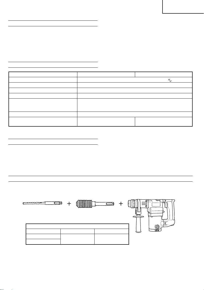
OPTIONAL ACCESSORIES (sold separately)
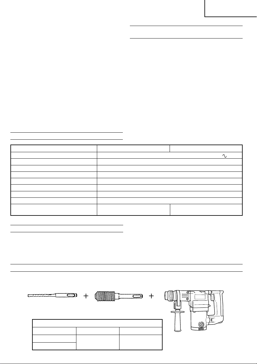
1. Drilling anchor holes (Rotation + Striking)
䡬 Drill bit (Slender shaft)
Drill bit (Slender shaft)
Drill bit (slender shaft)
Outer diameter Effective length Overall length
3.4 mm
3.5 mm
Adapter for slender shaft
(SDS-plus shank)
45 mm 90 mm
6
Page 8
English
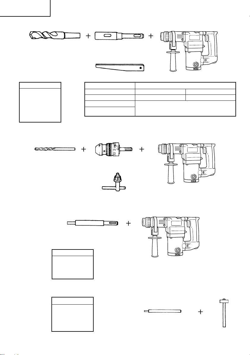
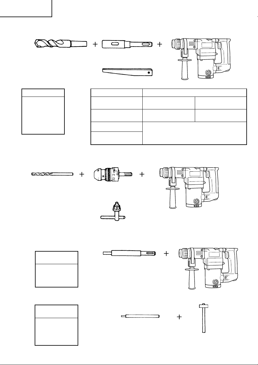
䡬 Drill bit (Taper shank) and taper shank adapter
Drill bit (Taper shank)
Outer diameter
11.0 mm
12.3 mm
12.7 mm
14.3 mm
14.5 mm
17.5 mm
21.5 mm
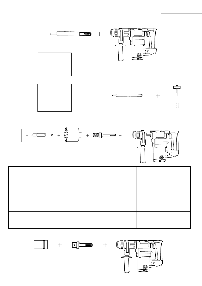
䡬 13 mm Hammer drill chuck (DH25PB only)
For drilling operations when using a straight shank bit for impact drilling with a hammer drill.
Straight shank bit
( )
for impact drill
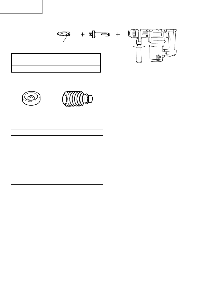
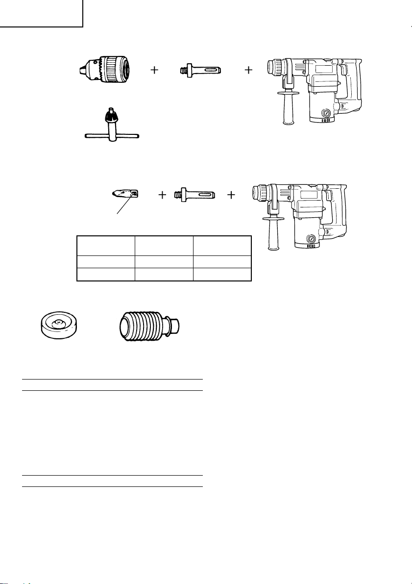
2. Anchor setting (Rotation + Striking)
䡬 Anchor setting adapter (for a rotary hammer)
Taper shank adapter
(SDS-plus shank)
Cotter
Taper mode Applicable drill bit
Morse taper (No.1) Drill bit (taper shank) 11.0 – 17.5 mm
Morse taper (No.2) Drill bit (taper shank) 21.5 mm
A-taper Taper shank adapter formed A-taper or B-taper
B-taper
13 mm Hammer drill chuck
(SDS-plus shank)
Chuck wrench
is provided as an optional accessory, but the
drill bits for them are not provided.
Anchor setting adapter (SDS-plus shank)
(for rotary hammer)
Overall length: 160, 260 mm
Anchor size
W1/4”
W5/16”
W3/8”
W1/2”
䡬 Anchor setting adapter (for a manual hammer)
Anchor size
W1/4”
W5/16”
W3/8”
W1/2”
W5/8”
7
Anchor setting adapter
(for a manual Hammer)
Page 9
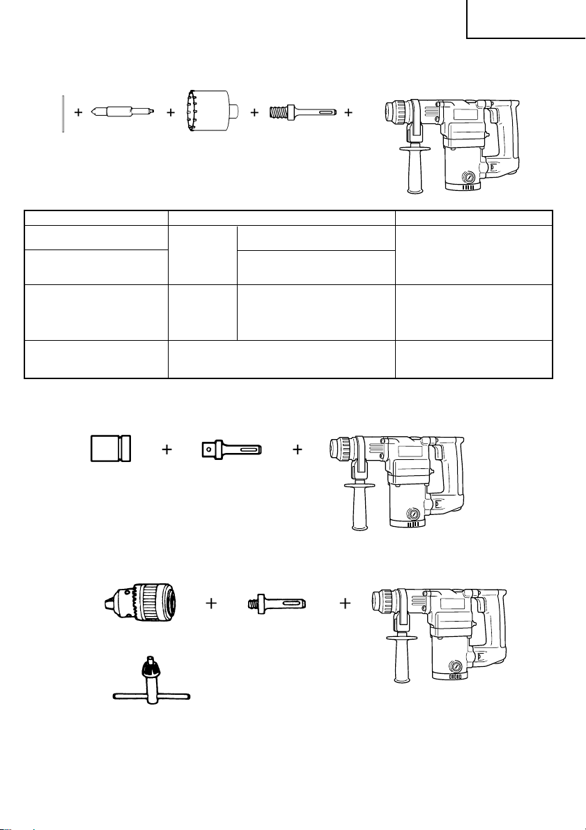
3. Large hole boring (Rotation + Striking)
䡬 Center pin, core bit, core bit shank and guide plate.
English
(Guide plate) Center pin Core bit Core bit shank
Center pin Core bit (outer diameter) Core bit shank
– 25 mm
Center pin (A) 35 mm
Center pin (B) (B) 65 mm Core bit shank (B)
Do not use core bits with with guide plate
outer diameter of 25 mm (The guide plate is not equipped with core bits
and 29 mm. with outer diameters of 25 mm and 29 mm.)
4. Bolt placing operation with Chemical Anchor. (Rotation + Striking)
Standard socket
( )
on the market
(A) 32 mm Core bit shank (A)
(SDS-plus shank)
12.7 mm Chemical Anchor Adapter
19 mm Chemical Anchor Adapter
(SDS-plus shank)
29 mm
38 mm
45 mm
50 mm
80 mm
90 mm
5. Drilling holes (Rotation only) (DH25PB only)
Drill chuck (13VLA) Chuck adapter (D)
(SDS-plus shank)
Chuck wrench
䡬 13 mm drill chuck ass’y (includes chuck wrench) and chuck (for drilling in steel or wood).
8
Page 10
English
6. Driving Screws (rotation only) (DH25PB only)
Bit No.
Bit No. Screw Size Length
No. 2 3 – 5 mm 25 mm
No. 3 6 – 8 mm 25 mm
7. Dust cup and Dust collector (B)
Dust cup
Optional accessories are subject to change without notice.
Dust collector (B)
Chuck adapter (D)
(SDS-plus shank)
APPLICATIONS
Rotation and striking function
䡬 Drilling anchor holes
䡬 Drilling holes in concrete
䡬 Drilling holes in tile
Rotation only function
䡬 Drilling in steel or wood
(with optional accessories)
䡬 Tightening machine screws, wood screws
(with optional accessories)
PRIOR TO OPERATION
1. Power source
Ensure that the power source to be utilized conforms
to the power requirements specified on the product
nameplate.
2. Power switch
Ensure that the power switch is in the OFF position.
If the plug is connected to a receptacle while the
power switch is in the ON position, the power tool
will start operating immediately, which could cause
a serious accident.
3. Extension cord
When the work area is removed from the power
source, use an extension cord of sufficient thickness
and rated capacity. The extension cord should be
kept as short as practicable.
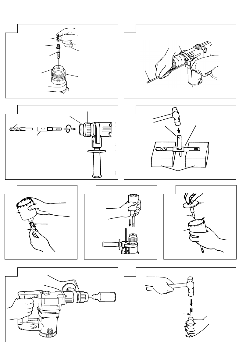
4. Mounting the drill bit (Fig. 1)
(1) To attach a drill bit (SDS-plus shank), fully pull the
grip in the direction of the arrow as shown in Fig.
1 and insert the drill bit as far as it will go while
manually turning.
(2) By releasing the grip, the drill bit will be secured.
(3) To remove the drill bit, fully pull the grip in the
direction of the arrow and pull out the drill bit.
9
8. Hammer grease A
500 g (in a can)
70 g (in a green tube)
30 g (in a green tube)
5. Installation of dust cup (standard accessory) or
dust collector (B) (Optional accessory) (Fig. 2,
Fig. 3)
When using a rotary hammer for upward drilling
operations attach a dust cup or dust collector (B)
to collect dust or particles for easy operation.
䡬 Installing the dust cup
Use the dust cup by attaching to the drill bit as
shown in Fig. 2.
When using a bit which has big diameter, enlarge
the center hole of the dust cup with this rotary
hammer.
䡬 Installing dust collector (B)
When using dust collector (B), insert dust collector
(B) from the tip of the bit by aligning it to the
groove on the grip. (Fig. 3)
CAUTION:
䡬 The dust cup and dust collector (B) are for exclusive
use of concrete drilling work. Do not use them for
wood or metal drilling work.
䡬 Insert dust collector (B) completely into the chuck
part of the main unit.
䡬 When turning the rotary hammer on while dust
collector (B) is detached from a concrete surface,
dust collector (B) will rotate together with the drill
bit. Make sure to turn on the switch after pressing
the dust cup on the concrete surface. (When using
dust collector (B) attached to a drill bit that has
more than 190 mm of overall length, dust collector
(B) cannot touch the concrete surface but rotates.
Therefore please use dust collector (B) by attaching
to drill bits which have 166 mm, 160 mm, and 110
mm overall length.
䡬 Dump particles after every two or three holes drilling.
䡬 Please replace the drill bit after removing dust
collector (B).
6. Selecting a driver bit
Screw heads or bits will be damaged should an
inappropriate bit for the screw diameter be employed
to drive in the screws.
Page 11

English
HOW TO USE
CAUTION:
To prevent accidents, make sure to turn the switch off
and disconnect the plug from the receptacle when the
drill bits and other various parts are installed or removed.
The power switch should also be turned off during a
work break and after work.
1. Switch operation
The rotation speed of the drill bit can be controlled
steplessly by varying the amount that the trigger
switch is pulled. Speed is low when the trigger
switch is pulled slightly and increases as the switch
is pulled more.
2. Rotation + striking (DH25PA and DH25PB)
This rotary hammer can be set to rotation and
striking mode by rotating the change lever (DH25PB
only) fully counter-clockwise to
(1) Mount the drill bit.
(2) Pull the trigger switch after applying the drill bit
tip to the drilling position. (Fig. 6)
(3) Pushing the rotary hammer forcibly is not necessary
at all. Pushing slightly so that drill dust comes out
gradually is sufficient.
CAUTION:
When the drill bit touches a rebar, the bit will stop
immediately and the rotary hammer will react to
revolve. Therefore grip the side handle and handle
tightly as shown in Fig. 6.
3. Rotation only (DH25PB)
The rotary hammer can be set to rotation only
mode by rotating the change lever fully clockwise
mark. (Fig. 7)
to
To drill wood or metal material using the drill chuck
and chuck adapter (optional accessory), carry out
as follows.
Installing drill chuck and chuck adapter: (Fig. 8)
(1) Mount the drill chuck to the chuck adapter.
(2) The part of the SDS-plus shank is the same as the
drill bit. Therefore, refer to the item of “Mounting
the drill bit” for attaching it.
CAUTIONS:
䡬 Application of force more than necessary will not
only decelerate the working efficiency, but it will
deteriorate the tip edge of the drill bit and reduce
the service life of the rotary hammer as well.
䡬 Do not attempt to drill anchor holes or holes in
concrete with the machine set in the rotation only
function.
䡬 Do not attempt to use the rotary hammer in the
rotation and striking function with the drill chuck
and chuck adapter attached. This would seriously
shorten the service life of each component of the
power tool.
4. When driving machine screws (Fig. 9)
First, insert the bit into the socket in the end of
chuck adapter (D).
Next, mount chuck adapter (D) on the main unit
using procedures described in 4 (1), (2), (3), put the
tip of the bit in the slots in the head of the screw,
grasp the main unit and tighten the screw.
CAUTIONS:
䡬 Exercise care not to excessively prolong driving
time, otherwise, the screws may be damaged by
excessive force.
mark. (Fig. 5)
䡬 Apply the rotary hammer perpendicularly to the
screw head when driving the screw; otherwise, the
screw head or bit will be damaged, or driving force
will not be fully transferred to the screw.
䡬 Do not attempt to use the rotary hammer in the
rotation and striking function with the chuck adapter
and bit attached.
5. When driving wood screws (Fig. 9)
(1) Selecting a suitable driver bit
Recommended to employ cross-recessed screws,
since the driver bit easily slips off the heads of
slotted-head screws.
(2) Driving in wood screws
䡬 Prior to driving in wood screws, make pilot holes
suitable for them in the wooden board. Apply the
bit to the screw head recesses and gently drive the
screws into the holes.
䡬 After rotating the rotary hammer at low speed for
a while until the wood screw is partly driven into
the wood, squeeze the trigger more strongly to
obtain the optimum driving force.
CAUTION:
Exercise care in preparing a pilot hole suitable for
the wood screw taking the hardness of the wood
into consideration. Should the hole be excessively
small or shallow, requiring much power to drive
the screw into it, the thread of the wood screw may
sometimes be damaged.
6. Using the stopper (Fig.10)
(1) Loosen the knob on the side handle, and insert the
stopper into the mounting hole on the side handle.
(2) Adjust the stopper position according to the depth
of the hole and tighten the knob securely.
7. How to use the drill bit (taper shank) and the taper
shank adapter
(1) Mount the taper shank adapter to the rotary hammer.
(Fig. 11)
(2) Mount the drill bit (taper shank) to the taper shank
adapter. (Fig. 11)
(3) Turn the switch ON, and drill a hole in prescribed
depth.
(4) To remove the drill bit (taper shank), insert the
cotter into the slot of the taper shank adapter and
strike the head of the cotter with a manual hammer
supporting on the rests. (Fig. 12)
HOW TO USE THE CORE BIT
(FOR LIGHT LOAD)
When boring penerating large holes use the core bit (for
light loads). At that time use with the center pin and the
core bit shank provided as optional accessories.
1. Mounting
CAUTION
Be sure to turn power OFF and disconnect the plug
from the receptacle.
(1) Mount the core bit to the core bit shank. (Fig. 13).
Lubricate the thread of the core bit shank to facilitate
disassembly.
(2) Mount the core bit to the rotary hammer (Fig. 14).
(3) Insert the center pin into the guide plate until it
stops.
(4) Engage the guide plate with the core bit, and turn
the guide plate to the left or the right so that it
does not fall even if it faced downward. (Fig. 15).
10
Page 12

English
2. How to bore (Fig. 16)
(1) Connect the plug to the power source.
(2) A spring is installed in the center pin.
Push it lightly to the wall or the floor perpendicularly.
Connect the core bit tip flush to the surface and
start operating.
(3) When boring about 5 mm in depth the position of
the hole will be established. Bore after that removing
the center pin and the guide plate from core bit.
(4) Application of excessive force will not only decelerate
the working efficiency, but it will deteriorate the tip
edge of the drill bit, resulting in reduced service
life of the rotary hammer.
CAUTION
When removing the center pin and the guide plate,
turn OFF the switch and disconnect the plug from
the receptacle.
3. Dismounting (Fig. 17)
Remove the core bit shank from the rotary hammer
and strike the head of the core bit shank strongly
two or three times with a manual hammer holding
the core bit, then the thread becomes loose and
the core bit can be removed.
LUBRICATION
Low viscosity grease is applied to this rotary hammer so
that it can be used for a long period without replacing
the grease. Please contact the nearest authorized service
center for grease replacement when any grease is leaking
from a loosened screw.
Further use of the rotary hammer with incorrect grease
will cause the machine inefficiency and reduce the service
life.
CAUTION:
A special grease is used with this machine, therefore, the
normal performance of the machine may be badly
affected by use of other grease. Please be sure to let one
of our authorized service center undertaking replacement
of the grease.
MAINTENANCE AND INSPECTION
1. Inspecting the drill bits
Since use of a dull tool will cause motor
malfunctioning and degraded efficiency, replace the
drill bit with new ones or resharpen them without
delay when abrasion is noted.
2. Inspecting the mounting screws:
Regularly inspect all mounting screws and ensure
that they are properly tightened. Should any of the
screws be loose, retighten them immediately. Failure
to do so could result in serious hazard.
3. Maintenance of the motor
The motor unit winding is the very “heart” of the
power tool. Exercise due care to ensure the
winding does not become damaged and/or wet
with oil or water.
4. Inspecting the carbon brushes (Fig. 18)
The motor employs carbon brushes which are
consumable parts. When they become worn to or
near “wear limit”, it could result in motor trouble.
When an auto-stop carbon brush is equipped, the
motor will stop automatically.
At that time, replace both carbon brushes with new
ones which have the same carbon brush numbers
shown in Fig. 18.
In addition, always keep carbon brushes clean and
ensure that they slide freely within the brush holders.
5. Replacing carbon brushes:
Disassemble the brush caps with a slotted-head
screwdriver. The carbon brushes can then be easily
removed.
6. Service parts list
A: Item No.
B: Code No.
C: No. Used
D: Remarks
CAUTION
Repair, modification and inspection of Hitachi Power
Tools must be carried out by an Hitachi Authorized
Service Center.
This Parts List will be helpful if presented with the
tool to the Hitachi Authorized Service Center when
requesting repair or other maintenance.
In the operation and maintenance of power tools,
the safety regulations and standards prescribed in
each country must be observed.
MODIFICATIONS
Hitachi Power Tools are constantly being improved
and modified to incorporate the latest technological
advancements.
Accordingly, some parts (i.e. code numbers and/or
design) may be changed without prior notice.
NOTE:
Due to HITACHI’s continuing program of research and
development, the specifications herein are subject to
change without prior notice.
IMPORTANT
Correct connection of the plug
The wires of the mains lead are coloured in accordance
with the following code:
Blue: -Neutral
Brown: -Live
As the colours of the wires in the mains lead of this tool
may not correspond with the coloured markings
identifying the terminals in your plug proceed as follows:
The wire coloured blue must be connected to the terminal
marked with the letter N or coloured black. The wire
coloured brown must be connected to the terminal
marked with the letter L or coloured red. Neither core
must be connected to the earth terminal.
NOTE:
This requirement is provided according to BRITISH
STANDARD 2769: 1984.
Therefore, the letter code and colour code may not be
applicable to other markets except The United Kingdom.
11
Page 13

Information concerning airborne noise and vibration
The measured values were determined according to
EN60745 and declared in accordance with ISO 4871.
Measured A-weighted sound power level: 101 dB (A)
Measured A-weighted sound pressure level: 90 dB (A)
Uncertainty KpA: 3 dB (A).
Wear ear protection.
The typical weighted root mean square acceleration
value: 9.5 m/s2.
English
12
Page 14

Deutsch
ALLGEMEINE SICHERHEITSMASSNAHMEN
WARNUNG!
Lesen Sie sämtliche Hinweise durch
Wenn nicht sämtliche nachstehenden Anweisungen
befolgt werden, kann es zu Stromschlag, Brand und/oder
ernsthaften Verletzungen kommen.
Der Begriff „Elektrowerkzeug“ bezieht sich in den
folgenden Warnhinweisen auf Elektrowerkzeuge mit Netz(schnurgebunden) oder Akkubetrieb (schnurlos).
BEWAHREN SIE DIESE ANWEISUNGEN AUF
1) Arbeitsbereich
a) Sorgen Sie für einen sauberen und gut
ausgeleuchteten Arbeitsbereich.
Zugestellte und dunkle Bereiche ziehen Unfälle
förmlich an.
b) Verwenden Sie Elektrowerkzeuge niemals an
Orten, an denen Explosionsgefahr besteht – zum
Beispiel in der Nähe von leicht entflammbaren
Flüssigkeiten, Gasen oder Stäuben.
Bei der Arbeit mit Elektrowerkzeugen kann es
zu Funkenbildung kommen, wodurch sich Stäube
oder Dämpfe entzünden können.
c) Sorgen Sie bei der Arbeit mit Elektrowerkzeugen
dafür, dass sich keine Zuschauer (insbesondere
Kinder) in der Nähe befinden.
Wenn Sie abgelenkt werden, können Sie die
Kontrolle über das Werkzeug verlieren.
2) Elektrische Sicherheit
a) Elektrowerkzeuge müssen mit passender
Stromversorgung betrieben werden.
Nehmen Sie niemals irgendwelche Änderungen
am Anschlussstecker vor.
Verwenden Sie bei Elektrowerkzeugen mit
Schutzkontakt (geerdet) niemals Adapterstecker.
Stecker im Originalzustand und passende
Steckdosen reduzieren das Stromschlagrisiko.
b) Vermeiden Sie Körperkontakt mit geerdeten
Gegenständen wie Rohrleitungen, Heizungen,
Herden oder Kühlschränken.
Bei Körperkontakt mit geerdeten Gegenständen
besteht ein erhöhtes Stromschlagrisiko.
c) Setzen Sie Elektrowerkzeuge niemals Regen oder
sonstiger Feuchtigkeit aus.
Wenn Flüssigkeiten in ein Elektrowerkzeug
eindringen, erhöht sich das Stromschlagrisiko.
d) Verwenden Sie die Anschlussschnur nicht
missbräuchlich. Tragen Sie das Elektrowerkzeug
niemals an der Anschlussschnur, ziehen Sie es
nicht damit heran und ziehen Sie den Stecker
nicht an der Anschlussschnur aus der Steckdose.
Halten Sie die Anschlussschnur von Hitzequellen,
Öl, scharfen Kanten und beweglichen Teilen fern.
Beschädigte oder verdrehte Anschlussschnüre
erhöhen das Stromschlagrisiko.
e) Wenn Sie ein Elektrowerkzeug im Freien
benutzen, verwenden Sie ein für den
Außeneinsatz geeignetes Verlängerungskabel.
Ein für den Außeneinsatz geeignetes Kabel
vermindert das Stromschlagrisiko.
3) Persönliche Sicherheit
a) Bleiben Sie wachsam, achten Sie auf das, was
Sie tun, und setzen Sie Ihren Verstand ein,
wenn Sie mit Elektrowerkzeugen arbeiten.
13
Benutzen Sie keine Elektrowerkzeuge, wenn Sie
müde sind oder unter Einfluss von Drogen,
Alkohol oder Medikamenten stehen.
Bei der Arbeit mit Elektrowerkzeugen können
bereits kurze Phasen der Unaufmerksamkeit zu
schweren Verletzungen führen.
b) Benutzen Sie Schutzausrüstung. Tragen Sie
immer einen Augenschutz.
Schutzausrüstung wie Staubmaske, rutschsichere
Sicherheitsschuhe, Schutzhelm und Gehörschutz
senken das Verletzungsrisiko bei angemessenem
Einsatz.
c) Vermeiden Sie unbeabsichtigten Anlauf. Achten
Sie darauf, dass sich der Schalter in der Aus(Off-) Position befindet, ehe Sie den Stecker
einstecken.
Das Herumtragen von Elektrowerkzeugen mit
dem Finger am Schalter und das Einstecken des
Steckers bei betätigtem Schalter zieht Unfälle
regelrecht an.
d) Entfernen Sie sämtliche Einstellwerkzeuge
(Einstellschlüssel), ehe Sie das Elektrowerkzeug
einschalten.
Ein an einem beweglichen Teil des
Elektrowerkzeugs angebrachter Schlüssel kann
zu Verletzungen führen.
e) Sorgen Sie für einen festen Stand. Achten Sie
jederzeit darauf, sicher zu stehen und das
Gleichgewicht zu bewahren.
Dadurch haben Sie das Elektrowerkzeug in
unerwarteten Situationen besser im Griff.
f) Kleiden Sie sich richtig. Tragen Sie keine lose
Kleidung oder Schmuck. Halten Sie Haar,
Kleidung und Handschuhe von beweglichen
Teilen fern.
Lose Kleidung, Schmuck oder langes Haar kann
von beweglichen Teilen erfasst werden.
g) Wenn Anschlüsse für Staubabsaug- und -
sammelvorrichtungen vorhanden sind, sorgen
Sie dafür, dass diese richtig angeschlossen und
eingesetzt werden.
Die Verwendung solcher Vorrichtungen kann
Staub-bezogene Gefahren mindern.
4) Einsatz und Pflege von Elektrowerkzeugen
a) Überanspruchen Sie Elektrowerkzeuge nicht.
Benutzen Sie das richtige Elektrowerkzeug für
Ihren Einsatzzweck.
Das richtige Elektrowerkzeug erledigt seine Arbeit
bei bestimmungsgemäßem Einsatz besser und
sicherer.
b) Benutzen Sie das Elektrowerkzeug nicht, wenn
es sich nicht am Schalter ein- und ausschalten
lässt.
Jedes Elektrowerkzeug, das nicht mit dem
Schalter betätigt werden kann, stellt eine Gefahr
dar und muss repariert werden.
c) Ziehen Sie den Netzstecker, ehe Sie
Einstellarbeiten vornehmen, Zubehörteile
tauschen oder das Elektrowerkzeug verstauen.
Solche präventiven Sicherheitsmaßnahmen
verhindern den unbeabsichtigten Anlauf des
Elektrowerkzeugs und die damit verbundenen
Gefahren.
Page 15

Deutsch
d) Lagern Sie nicht benutzte Elektrowerkzeuge
außerhalb der Reichweite von Kindern, lassen
Sie nicht zu, dass Personen das Elektrowerkzeug
bedienen, die nicht mit dem Werkzeug selbst
und/oder diesen Anweisungen vertraut sind.
Elektrowerkzeuge in ungeschulten Händen sind
gefährlich.
e) Halten Sie Elektrowerkzeuge in Stand. Prüfen
Sie auf Fehlausrichtungen, sicheren Halt und
Leichtgängigkeit beweglicher Teile,
Beschädigungen von Teilen und auf jegliche
andere Zustände, die sich auf den Betrieb des
Elektrowerkzeugs auswirken können.
Bei Beschädigungen lassen Sie das
Elektrowerkzeug reparieren, ehe Sie es benutzen.
Viele Unfälle mit Elektrowerkzeugen sind auf
schlechte Wartung zurückzuführen.
f) Halten Sie Schneidwerkzeuge scharf und sauber.
Richtig gewartete Schneidwerkzeuge mit scharfen
Schneidkanten bleiben weniger häufig hängen
und sind einfacher zu beherrschen.
g) Benutzen Sie Elektrowerkzeuge, Zubehör,
Werkzeugspitzen und Ähnliches in
Übereinstimmung mit diesen Anweisungen und
auf die für das jeweilige Elektrowerkzeug
bestimmungsgemäße Weise – beachten Sie
dabei die jeweiligen Arbeitsbedingungen und
die Art und Weise der auszuführenden Arbeiten.
Der bestimmungswidrige Einsatz von
Elektrowerkzeugen kann zu gefährlichen
Situationen führen.
5) Service
a) Lassen Sie Elektrowerkzeuge durch qualifizierte
Fachkräfte und unter Einsatz passender,
zugelassener Originalteile warten.
Dies sorgt dafür, dass die Sicherheit des
Elektrowerkzeugs nicht beeinträchtigt wird.
VORSICHT
Von Kindern und gebrechlichen Personen fernhalten.
Werkzeuge sollten bei Nichtgebrauch außerhalb der
Reichweite von Kindern und gebrechlichen Personen
aufbewahrt werden.
VORSICHTSMASSNAHMEN BEI BENUTZUNG
DES BOHRHAMMERS
1. Ohrenstöpsel zum Schutz der Ohren während des
Betriebs tragen.
2. Die Bohrerspitze während oder unmittelbar nach
dem Betrieb nicht berühren. Die Bohrerspitze
wird während des Betriebs sehr heiß, sobaß es
zu ernsthaften Verbrennungen führen könnte.
3. Bevor man on der Wand, im Boden oder an der
Decke etwas ausbricht, meißelt oder bohrt, muß
man sich sorgfältig davon überzeugen, ob keine
elektrischen Kabel oder Kabelrohre darunter liegen.
4. Immer den körper-Handgriff und Seiten-Handgriff
des Elektrowerkzeugs festhalten, weil die
entstehende Gegenkraft sonst zu einem ungenauen
und gefährlichen Arbeiten führt.
TECHNISCHE DATEN
Modell DH25PA DH25PB
Spannung (je nach Gebiet)* (110V, 115V, 120V, 127V, 220V, 230V, 240V)
Leistungsaufnahme 650W*
Leerlaufdrehzahl 0 – 1100/min.
Vollastschlagzahl 0 – 4000/min.
Kapazität: Beton 3,4 – 25 mm
Gewicht
(ohne Kabel und Handgriff)
Funktion Schlag-und Drehbohrer
*Vergessen Sie nicht, die Produktangaben auf dem Typenschild zu überprüfen, da sich diese je nach Verkaufsgebiet
ändern.
Stahl 13 mm
Holz 32 mm
3,4 kg
Schlag-und Drehbohrer
nur Drehung
STANDARDZUBEHÖR
(1) Tasche (Plastk) .......................................................... 1
(2) Handgriff .................................................................... 1
(3) Anschlag .................................................................... 1
(4) Staubfänger ............................................................... 1
Das Standardzubehör kann ohne vorherige
Bekanntmachung jederzeit geändert werden.
14
Page 16

Deutsch
SONDERZUBEHÖR (separat zu beziehen)
1. Bohren von Ankerlöchern (Schlag-und Drehbohrer)
䡬 Bohrer (dünner Schaft)
Bohrer (dünner Shaft)
Bohrer (dünner Schaft)
Außendurchmesser Arbeitslänge Gesamtlänge
3,4 mm
3,5 mm
䡬 Bohrer (Kegelschaft) und Konusschaftadapter
Bohrer (Kegelschaft)
Außendurchmesser
11,0 mm
12,3 mm
12,7 mm
14,3 mm
14,5 mm
17,5 mm
21,5 mm
Adapter für dünnen Schaft
(SDS-Plus Schaft)
45 mm 90 mm
Konusschaftadapter
(SDS-Plus Schaft)
Dorn
Konusschaftadapter Anwendbarer Bohrer
Morsekonus (Nr.1) Bohrer (Konusschaft) 11,0 – 17,5 mm
Morsekonus (Nr.2) Bohrer (Konusschaft) 21,5 mm
A-Konus Der Konusschaftadapter in der Form des A-oder
B-Konus der passende Bohrer separat zu beziehen.
B-Konus wird nach Wunsch geliefert, doch ist
䡬 13 mm Bohrhammerfutter (nur DH25PB)
Zum Bohrbetrieb mit gerader Schlagspitze für schlagbohrer mit bohrhammer.
Gerade Meißelspitze
(
für Schlagbohrer
15
13 mm Bohrhammerfutter
(SDS-Plus Schaft)
)
Bohrfutterschlüssel
Page 17
2. Ankereinsatz (Schlag-und Drehbohren)
䡬 Adapter für Ankerbefestigung (mit Bohrhammer)
Adapter für Ankerbefestigung (SDS-Plus Schaft)
(mit Bohrhammer)
Gesamtlänge: 160 mm 260 mm
Ankergröße
W1/4”
W5/16”
W3/8”
W1/2”
䡬 Adapter für Ankerbefestigung (mit dem Handhammer)
Ankergröße
W1/4”
W5/16”
W3/8”
W1/2”
W5/8”
3. Lochbohren mit weitem Durchmesser (Schlag-und Drehbohrer)
䡬 Mittelstift, Bohrkrone, Bohrkronenschenkel und Führungsplatte.
Adapter für Ankerbefestigung
(mit dem Handhammer)
Deutsch
(Führungsplatte) Mittelstift Bohrkrone Bohrkronenschenkel
Mittelstift Bohrkrone (Außendurchmesser) Bohrkronenzapfen
– 25 mm
Mittelstift (A) 35 mm
Mittelstift (B) (B) 65 mm Bohrkronenzapfen (B)
Niemals Bohrkronen mit Mit Führungsplatte
einem Außendurchmesser (Die Führungsplatte ist nicht für Bohrkronen
von 25 mm oder 29 mm mit einem Außendurchmesser von 25 mm
verwenden. oder 29 mm besitzen.)
4. Bolzenplazierung für Chemical Anchor. (Schlag-und Drehbohren)
Sockel auf
( )
markierter stelle
12,7 mm Adapter für Chemical Anchor
19 mm Adapter für Chemical Anchor
(A) 32 mm Bohrkronenzapfen (A)
(SDS-Plus Schaft)
(SDS-Plus Schaft)
29 mm
38 mm
45 mm
50 mm
80 mm
90 mm
16
Page 18
Deutsch
5. Löcherbohren (nur Drehung) (nur DH25PB)
Bohrfutter (13VLA)
Bohrfutterschlüssel
䡬 Zum Bohren von Stahl oder Holz: Bohrfuttervorrichtung von 13 mm (einschl Futterschlüssel), Futteradapter.
6. Schneidschraube (nur Drehung) (nur DH25PB)
Bohrespitzennummer
Bohrerspitzen-
nummer
Nr.2 3 - 5 mm 25 mm
Nr.3 6 - 8 mm 25 mm
7. Staubschale und Staubfang (B)
Staubschale
Das Sonderzubehöre kann ohne vorherige Bekanntmachung jederzeit geändert werden.
SchraubengrößeLänge
Staubfang (B)
ANWENDUNGEN
Schlag- und Drehbohrfunktion
䡬 Bohren von Ankerlöchern
䡬 Bohren von Löchern in Beton
䡬 Bohren von Löchern in Kachel
Nur Drehbohrfunktion
䡬 Bohren in Stahl oder Holz
(mit Sonderzubehör)
䡬 Anziehen von Maschinenschrauben, Holzschrauben.
(mit Sonderzubehör)
VOR INBETRIEBNAHME
1. Netzspannung
Prüfen, daß die zu verwendende Netzspannung der
Angabe auf dem Typenschild entspricht.
2. Netzschalter
Prüfen, daß der Nezschalter auf „AUS” steht. Wenn
der Stecker an das Netz angeschlossen wird,
während der Schalter auf „EIN” steht, beginnt das
Werkzeug sofort zu laufen, was gefährlich ist.
17
Bohrfutteradapter (D)
(SDS-Plus Schaft)
Bohrfutteradapter (D)
(SDS-Plus Schaft)
8. Hammer Schmierfett A
3. Verlängerungskabel
4. Anbringung des Bohrers (Abb. 1)
(1) Zum Anbringen des Bohrers (SDS-Plus Schaft) gen
(2) Den Griff loslassen, und der Bohrer ist befestigt.
(3) Zum Entfernen des Bohrers den Griff in Pfeilrichtung
5. Beim Installieren der Staubschale (Standardzubehör)
500 g (Dose)
70 g (in grüner Tube)
30 g (in grüner Tube)
Wenn der Arbeitsbereich nicht in der Nähe des
Netzanschlusses liegt, ist ein Verlängerungskabel
ausreichenden Querschnitts und ausreichender
Nennleistung zu verwenden. Das
Verlängerungskabel sollte so kurz wie möglich
gehalten werden.
Griff ganz in Pfeilrichtung ziehen, wie in Abb. 1
gezeigt, und den Bohrer drehend ganz bis zum
Anschlag einsetzen.
ziehen, und den Bohrer herausziehen.
oder des Staubfangs (B) (Zonderzubehör) (Abb. 2,
Abb. 3)
Wenn ein Bohrhammer zum Bohren nach oben
ohne Staubfangadapter verwendet wird, eine
Staubkappe oder einen Staubfang (B) zum Auffangen
von Staub und Partikeln zum leichten Betrieb
anbringen.
Page 19

Deutsch
䡬 Anbringen der Staubschale
Die Staubschale durch Anbringen an die Bohrspitze
wie in Abb. 2 gezeigt verwenden.
Bei Bohrspitzen mit großem Durchmesser das
Mittenloch der Staubschale mit diesem Bohrhammer
vergrößern.
䡬 Anbringen des Staubfangs (B)
Bei Verwendung des Staubfangs (B) den Staubfang
(B) von der Spitze der Bohrspitze einführen, und an
die Rille an der Spitze ansetzen. (Abb. 3)
VORSICHT:
䡬 Die Staubschale und der Staubfang (B) sind nur für
Bohren in Beton gedacht. Nicht für Bohrarbeiten
in Holz oder Metall verwenden.
䡬 Den Staubfang (B) vollständig in den Futterteil der
Haupteinheit einsetzen.
䡬 Wenn am Bohrhammer gedreht wird, während die
Staubfang (B) von der Betonoberfläche abgenommen
ist, dreht sich die Staubfang (B) zusammen mit der
Bohrspitze. Immer am Schalter drehen, nachdem
die Staubschale auf die Betonoberfläche gedrückt
ist. (Bei Verwendung der Staubfang (B) durch
Anbringen einer Bohrspitze mit mehr als 190 mm
Gesamtlänge kann die Staubfang (B) nicht die
Betonoberfläche berühren und dreht sich.) Darum
immer Bohrspitzen mit 166, 160 und 110 mm
Gesamtlänge verwenden.
䡬 Nach dem Bohren von jeweils zwei oder drei Löchern
die Partikel aus dem Staubfang ausschütten.
䡬 Die Bohrspitze nach dem Abnehmen der Staubfang
(B) austauschen.
6. Wahl der Schrauberspitze
Wenn keine dem Schraubendurchmesser
angemessene Schrauberspitze zum Einschrauben
von Schrauben verwendet wird, kann es zu
Beschädigung des Schraubenkopfes bzw. der
Schrauberspitze kommen.
GEBRAUCHSANWEISUNG
VORSICHT:
Zur Verhütung von Unfällen beim Anbringen und
Entfernen von Bohrern und anderen Teilen immer den
Schalter ausschalten und den Stecker des Netzkabels
aus der Steckdose ziehen. Der Schalter sollte auch
während Arbeitsunterbrechungen und nach der Arbeit
ausgeschaltet werden.
1. Betätigung des Schalters
Die Drehzahl des Bohrers kann durch Veränderung
des Drucks auf den Drückerschalter gesteuert
werden. Die Geschwindigkeit ist gering, wenn der
Drückerschalter nur leicht gezogen ist und erhöht
sich, wenn der Schalter weiter durchgezogen wird.
2. Schlag- und Drehbohren (DH25PA und DH25PB)
Dieser Bohrhammer kann durch Drehen des
Umschalthebels (nur DH25PB) bis zum Anschlag
gegen den Uhrzeigersinn zur
Schlag- und Drehbohrer verwendet werden. (Abb. 5)
(1) Die Bohrerspitze anbringen.
(2) Den Triggerschalter nach Anbringen in Bohrlage
der Bohrerspitze ziehen. (Abb. 6)
(3) Es ist nicht nö tig den Bohrhammer stark
anzudrücken. Leichtes Andrücken, so daß der
Bohrstaub regelmäßig herausfällt, ist gerade
genügend.
Markierung als
ACHTUNG:
Wenn der Bohrer mit Baueisenstangen in Berührung
kommt, stoppt sofort der Bohren, und nur der
Bohrhammer dreht sich. Deshalb den Handgriff gut
fest halten wie in Abb. 6 gezeigt.
3. Nur Drehbohren (DH25PB)
Durch Drehen des Umschalthebels bis zum Anschlag
im Uhrzeigersinn zur
Bohrhammer als Drehbohrer verwendet werden.
(Abb. 7)
Zum Bohren von Holz und Metall einen
Bohrfutteradapter und ein Bohrfutter (zubehör)
verwenden.
Anbringung des Bohrfutters und Bohrfutteradapters:
(Abb. 8)
(1) Das Bohrfutter am Adapter anbringen.
(2) Das Teil des SDS-Plus Schaftes ist das gleiche wie
der Bohrer. Zum Anbringen deshalb auf den Punkt
“Anbringung des Bohrers” beziehen.
ACHTUNG:
䡬 Ü bermäßiger Druck wird nicht die Arbeit
beschleunigen und kann dazu die Bohrerleistung
und auch die Lebensdauer des Bohrhammers
vermindern.
䡬 Nicht versuchen Ankerlöcher oder gewöhnliche
Löcher in Beton zu bohren, wenn das Werkzeug nur
auf Drehbohrfunktion eingestellt ist.
䡬 Nicht versuchen den Bohrhammer Schlag-und
Drehbohren zu verwenden, wenn das Bohrfutter
und der Bohrfutteradapter angebracht sind. Sonst
wird die Lebensdauer des Werkzeuges verkürzt
werden.
4. Einschrauben von Maschinenschrauben (Abb. 9)
Zuerst die Drehspitze in den Sockel am Ende des
Futteradapters (D) einsetzen.
Dann den Futteradapter (D) mit dem in 4 (1), (2),
(3) beschriebenen Verfahren an die Haupteinheit
anbringen, die Spitze des Drehstücks in die Schlitze
auf dem Schraubenkopf setzen, die Haupteinheit
fest greifen und die Schrauben festziehen.
VORSICHT:
䡬 Nicht mehr als nötig die Schraubzeit verlängern, um
Beschädigung der Schrauben zu vermeiden.
䡬 Den Bohrhammer senkrecht beim Einschrauben einer
Schraube an den Schraubenkopf ansetzen; sonst
könnte der Schraubenkopf oder die Bohrerspitze
beschüdigt werden, oder die Antriebskraft mag nicht
volkommen der Schraube übertragen werden.
䡬 Nicht versuchen, den Schlagbohrer in Schlag-Bohr-
Betriebsart zu verwenden, wenn Futteradapter und
Bohrspitze aufgesetzt sind.
5. Einschrauben von Holzschrauben (Abb. 9)
(1) Wahl einer passenden Bohrerspitze
So sehr wie möglich Kreuzkopfschrauben verwenden
da die Bohrerspitze leicht von gewöhnlichen
Schraubenköpfen abrutscht.
(2) Eischrauben
䡬 Vor dem Einschrauben von Holzschrauben, passende
Löcher im Holz orbereiten. Die Bohrerspitze an die
Schraubenkopfspalten ansetzen und die Schraube
sanft ins Holz einschrauben.
䡬 Nachdem sich der Bohrerhammer bei kleiner
Geschwindigkeit für eine Weile gedrecht hat bis die
Schraube zum Teil eingeschraubt wurde, fester auf
den Trigger drücken um optimale Antriebskraft zu
erreichen.
Markierung kann der
18
Page 20

Deutsch
VORSICHT:
Gut darauf achten, daß die Vorbereitung eines
passenden Loches für die Schraube gemäß der
Härte des Holzes durchgeführt wird. Falls das Loch
zu klein oder nicht tief genung sein sollte, und
dadurch große Kraftanwendung zum Einschrauben
erforderlich wird, kann das Schraubengewinde
manchmal beschädigt werden.
6. Verwendung des Anschlags (Abb. 10)
(1) Den Knopf am Seitenhandgriff lösen und den
Anschlag in das Anbringungsloch im Seitenhandgriff
einschieben.
(2) Die Anschlagposition entsprechend der Lochtiefe
einstellen und den Knopf fest anziehen.
7. Benutzung des Bohrers (Kegelschafts) und des
Kegelschaftadapters
(1) Den Kegelschaftadapter am Bohrhammer anbringen
(Abb. 11).
(2) Den Bohrer (Kegelschaft) am Kegelschaftadapter
anbringen. (Abb. 11)
(3) Den Schalter einschalten und ein Loch mit der
vorgegebenen Tiefe bohren.
(4) Zur Entferung des Bohrers (Kegelschafts) einen Dorn
in den Schlitz des Kegelschaftadapters einführen
und mit einem Hammer gestüzt durch eine Auflage
auf den Kopf des Dorns schlagen (Abb. 12)
BENUTZUNG DER BOHRKRONE
(FÜR GERINGE BELASTUNG)
Zur Bohrung großer Löcher eine Bohrkrone verwenden
(geringe Belastung). Dafür muß der Zentriestift und
Bohrkronenzapfen (beides Sonderzubehör) verwendet
werden.
1. Anbringen
ACHTUNG
Vor dem Anbringen das Gerät ausschalten und von
der Steckdose trennen.
(1) Die Bohrkrone am Bohrkronenzapfen anbringen
(Abb. 13). Für die Entfernung das Gewinde des
Bohrkronenzapfens schmieren.
(2) Den Bohrkronenzapfen am Bohrhammer anbringen
(Abb. 14).
(3) Den Zentrierstift vollständig bis zum Anschlag in die
Führungsplatte einführen.
(4) Dann die Führungsplatte in die Bohrkrone einsetzen
und nach links oder rechts drehen, sodaß sie nicht
herausfällt, wenn sie nach unten zeigt. (Abb. 15)
2. Bohrung (Abb. 16)
(1) Den Stecker an die Steckdose anschließen.
(2) Der Zentrierstift ist mit einer Feder versehen. Diese
Feder leicht senkrecht gegen die Wand bzw. den
Boden drücken. Die Fläche mit der Bohrkronenspitze
abtasten und das Gerät einschalten.
(3) Wenn eine Bohrtiefe von 5 mm erreicht worden ist,
ist die Position des Bohrlochs fixiert. Dann nach
Entfernung des Zentrierstifts und der Führungsplatte
von der Bohrkrone mit der Bohrung beginnen.
(4) Wenn beim Bohren übermäßige Gewalt angewandt
wird, wird der Bohrzapfenrand der Bohrkrone
beschädigt, wodurch die Lebensdauer des
Bohrhammers verkürzt wird.
ACHTUNG
Vor entfernung des Zentrierstifts und der
Führungsplate das Gerät ausschalten und von der
Steckdose trennen.
3. Entfernung (Abb. 17)
Den Bohrkronenzapfen vom Bohrhammer entfernen
und mit einem Hammer zwei oder drei mal kräftig
auf den Kopf des Bohrkronenzapfens schlagen,
während die Bohrkrone gehalten wird. Das Gewinde
lockert sich dann und die Bohrkrone kann entfernt
werden.
SCHMIERUNG
Für diesen Bohrhammer sollte ein Schmierfett mit
niedriger Viskosität verwendet werden, damit er für lange
Zeit ohne Schmierfettwechsel verwendet werden kann.
Sollte Schmierfett wegen gelöster Schrauben austreten,
wenden Sie sich bitte für das Auswechseln an die
nächstgelegene autorisierte Kundendienststelle.
Wird der Bohrhammer in einem solchen Fall
weiterverwendet, wird die Wirksamkeit des Gerätes
beeinträchtigt und die Lebensdauer verkürzt.
ACHTUNG:
Es sollte nur das vorgeschriebene Schmierfett verwendet
werden. Wenn ein anderes Schmierfett verwendet wird,
kann die Leistung des Gerätes beeinträchtigt werden.
Wenden Sie sich bitte für Auswechseln des Schmierfetts
an eine unserer autorisierten Kundendienststellen.
WARTUNG UND INSPEKTION
1. Inspektion des Bohrers
Fortgesetzte Verwendung eines stumpfen oder
beschädigten Bohrers führt zu verminderter
Bohrleistung und kann den Motor der Bohrmaschine
erheblich überbelasten. Den Bohrer regelmäßig
prüfen und erforderlichenfalls durch einen neuen
Bohrer ersetzen.
2. Inspektion der Befestigungsschrauben:
Alle Befestigungsschrauben werden regelmäßig
inspiziert und geprüft, ob sie gut angezogen sind.
Wenn sich eine der Schrauben lockert, muß sie
sofort wieder angezogen werden. Geschieht das
nicht, kann das zu erheblichen Gefahren führen.
3. Wartung des Motors:
Die Motorwicklung ist das „HERZ” des
Elektrowerkzeugs. Daher ist besonders sorgfältig
darauf zu achten, daß die Wicklung nicht beschädigt
wird und/oder mit Öl oder Wasser in Berührung
kommt.
4. Inspektion der Kohlenbürsten (Abb. 18)
Der Motor ist mit Kohlenbürsten ausgestattet. Wenn
sie sich abnützen oder sich der “Verschleißgrenze”
nähern, könnte es zu Motorschaden führen. Wenn
der Motor mit einer Auto-Stop Kohlenbürste
ausgestattet ist, wird er automatisch gestoppt.
Wechseln Sie dann beide Kohlenbürsten gegen neue
aus, die dieselbe Bürstennummer haben wie in der
Abb. 18 gezeigt.
Außerdem, achten Sie darauf, daß die Kohlenbürsten
immer sauber sind und frei im Bürstenhalter gleiten.
19
Page 21

5. Austausch einer Kohlebürste:
Der Bürstendeckel wird mit einem Steckschlüssel
abmontiert. Dann kann die Kohlebürste leicht entfernt
werden.
6. Liste der Wartungsteile
A: Punkt Nr.
B: Code Nr.
C: Verwendete Anzahl
D: Bemerkungen
ACHTUNG
Reparatur, Modifikation und Inspektion von HitachiElektrowerkzeugen müssen durch ein autorisiertes
Hitachi-Kundendienstzentrum durchgeführt werden.
Diese Teileliste ist hilfreich, wenn sie dem
autorisierten Hitachi-Kundendienstzentrum
zusammen mit dem Werkzeug für Reparatur oder
Wartung ausgehändigt wird.
Bei Betrieb und Wartung von Elektrowerkzeugen
müssen die Sicherheitsvorschriften und Normen
beachtet werden.
MODIFIKATIONEN
Hitachi-Elektrowerkzeuge werden fortwährend
verbessert und modifiziert, um die neuesten
technischen Fortschritte einzubauen.
Dementsprechend ist es möglich, daß einige Teile
(z.B. Codenummern bzw. Entwurf) ohne vorherige
Benachrichtigung geändert werden.
ANMERKUNG:
Aufgrund des ständigen Forschungs-und Entwicklungsprogramms von HITACHI sind Änderungen der hierin
gemachten technischen Angaben nicht ausgeschlossen.
Deutsch
Information über Betriebslärm und Vibration
Die gemessenen Werte wurden entsprechend EN60745
bestimmt und in Übereinstimmung mit ISO 4871
ausgewiesen.
Gemessener A-gewichteter Schallpegel: 101 dB (A)
Gemessener A-gewichteter Schalldruck: 90 dB (A)
Messunsicherheit KpA: 3 dB (A)
Bei der Arbeit immer einen Ohrenschutz tragen.
Der typische gewogene quadratische Mittelwert für die
Beschleunigung ist 9,5 m/s2.
20
Page 22

Français
CONSIGNES DE SÉCURITÉ GÉNÉRALES
AVERTISSEMENT!
Lire toutes les instructions
Tout manquement à observer ces instructions peut
engendrer des chocs électriques, des incendies et/ou
des blessures graves.
Le terme "outil électrique" qui figure dans l'ensemble
des avertissements ci-dessous se réfère aux outils
électriques (câblé) ou aux outils à piles (sans fil).
CONSERVER CES INSTRUCTIONS
1) Aire de travail
a) Maintenir l'aire de travail propre et bien éclairée.
Les endroits encombrés et sombres sont propices
aux accidents.
b) Ne pas utiliser d'outils électriques en présence
de liquides, gaz ou poussière inflammables, au
risque de provoquer une explosion.
Les outils électriques créent des étincelles
susceptibles d'enflammer la poussière.
c) Ne pas laisser les enfants et les visiteurs
s'approcher de vous lorsque vous utiliser un
outil électrique.
Les distractions peuvent faire perdre le contrôle.
2) Sécurité électrique
a) Les prises de l'outil électrique doivent
correspondre à la prise secteur.
Ne jamais modifier la prise.
Ne pas utiliser d'adaptateurs avec les outils
électriques mis à la masse.
Les prises non modifiées et les prises secteurs
correspondantes réduisent les risques de choc
électrique.
b) Eviter tout contact avec les surfaces mises à la
masse telles que les tuyaux, radiateurs, bandes
et réfrigérateurs.
Le risque de choc électrique est accru en cas de
mise à la masse du corps.
c) Ne pas exposer les outils électriques à la pluie
ou à des conditions humides.
Si l'eau pénètre dans l'outil, cela augmente les
risques de choc électrique.
d) Ne pas utiliser le cordon à tort. Ne jamais utiliser
le cordon pour transporter ou débrancher l'outil
électrique.
Maintenir le cordon loin de la chaleur, de l'huile,
des bords pointus ou des pièces mobiles.
Les cordons endommagés ou usés augmentent
les risques de choc électrique.
e) En cas d'utilisation d'un outil électrique à
l'extérieur, utiliser un cordon de rallonge adapté
à un usage extérieur.
L'utilisation d'un cordon adapté à l'usage extérieur
réduit les risques de choc électrique.
3) Sécurité personnelle
a) Restez alerte, regarder ce que vous faites et
usez de votre bon sens en utilisant un outil
électrique.
Ne pas utiliser d'outil électrique si vous êtes
sous l'influence de drogues, d'alcool ou de
médicaments.
Pendant l'utilisation d'outils électrique, un instant
d'inattention peut entraîner des blessures graves.
b) Utiliser des équipements de sécurité. Toujours
porter des verres de protection.
21
L'utilisation d'équipements de sécurité tels que
les masques anti-poussière, les chaussures de
sécurité anti-dérapantes, les casques ou les
protections auditives dans des conditions
appropriées réduisent les risques de blessures.
c) Eviter les démarrages accidentels. Veiller à ce
que l'interrupteur soit en position d'arrêt avant
de brancher l'outil.
Transporter les outils électriques avec le doigt sur
l'interrupteur ou brancher les outils électriques
avec l'interrupteur en position de marche peut
entraîner des accidents.
d) Retirer toute clé de sécurité ou clé avant de
mettre l'outil électrique en marche.
Laisser une clé ou une clé de sécurité sur une
partie mobile de l'outil électrique peut engendrer
des blessures.
e) Ne pas trop se pencher. Toujours garder une
bonne assise et un bon équilibre pendant le
travail.
Cela permet un meilleur contrôle de l'outil
électrique dans des situations imprévisibles.
f) Porter des vêtements adéquats. Ne pas porter
de vêtements amples ni de bijoux. Maintenir les
cheveux, les vêtements et les gants loin des
pièces mobiles.
Les vêtements amples ou les cheveux longs
peuvent se prendre dans les pièces mobiles.
g) En cas de dispositifs destinés au raccordement
d'installations d'extraction et de recueil de la
poussière, veiller à ce qu'ils soient correctement
raccordés et utilisés.
L'utilisation de ces dispositifs peut réduire les
dangers associés à la poussière.
4) Utilisation et entretien d'un outil électrique
a) Ne pas forcer sur l'outil électrique. Utiliser l'outil
électrique adapté à vos travaux.
Le bon outil électrique fera le travail mieux et en
toute sécurité au régime pour lequel il a été conçu.
b) Ne pas utiliser l'outil électrique si l'interrupteur
ne le met pas en position de marche et d'arrêt.
Tout outil ne pouvant être contrôlé par
l'interrupteur est dangereux et doit être réparé.
c) Débrancher la prise avant de procéder à des
réglages, au remplacement des accessoires ou
au stockage des outils électriques.
Ces mesures préventives de sécurité réduisent les
risques de démarrage accidentel de l'outil électrique.
d) Stockez les outils électriques inutilisés hors de
la portée des enfants et ne pas laisser des
personnes non familiarisées avec l'outil ou ces
instructions utiliser l'outil électrique.
Les outils électriques sont dangereux entre les
mains d'utilisateurs non habilités.
e) Entretenir les outils électriques. Vérifier l'absence
de mauvais alignement ou d'arrêt,
d'endommagement de pièces ou toute autre
condition susceptible d'affecter l'opération de
l'outil.
Si l'outil est endommagé, le faire réparer avant
utilisation.
De nombreux accidents sont dus à des outils mal
entretenus.
f) Maintenir les outils coupants aiguisés et propres.
Des outils coupants bien entretenus avec des
bords aiguisés sont moins susceptibles de se
coincer et plus simples à contrôler.
Page 23
Français
g) Utiliser l'outil électrique, les accessoires et les
mèches de l'outil, etc. conformément à ces
instructions et de la manière destinée pour le
type précis d'outil électrique, en tenant compte
des conditions d'utilisation et du travail à réaliser.
L'utilisation de l'outil électrique pour des
opérations différentes de celles pour lesquelles il
a été conçu est dangereuse.
5) Service
a) Faire entretenir l'outil électrique par un technicien
habilité à l'aide de pièces de rechange identiques
exclusivement.
Cela garantira le maintien de la sécurité de l'outil
électrique.
PRECAUTIONS
Maintenir les enfants et les personnes infirmes
éloignés.
Lorsque les outils ne sont pas utilisés, ils doivent
être rangés hors de portée des enfants et des
personnes infirmes.
PRECAUTIONS POUR L’UTILISATION DU
PERFORATEUR PERCUSSION
1. Utiliser des bouche-oreilles pour protéger vos
oreilles pendant le fonctionnement.
2. Ne pas toucher le foret pendant ou immédiatement
après le fonctionnement. Il devient très chaud et
peut causer des brûlures.
3. Avant de briser, découper ou percer un mur, le
plancher ou le plafond, s’assurer qu’aucun câble
électrique ou conduit n’y soit noyé.
4. Maintenir toujours fermenent la poignée principale
et la poignée latérale de la machine. Dans le cas
contraire, la force de recul peut amoindrir la
précision de travail et présenter aussi quelque
danger.
SPECIFICACIONS
Modèle DH25PA DH25PB
Tension (par zone)* (110V, 115V, 120V, 127V, 220V, 230V, 240V)
Puissance 650W*
Vitesse sans charge 0 – 1100/min.
Vitesse de percussion à pleine charge 0 – 4000/min.
Capacité:béton 3,4 – 25 mm
acier 13 mm
bois 32 mm
Poids (sans fil et poignée latérale) 3,4 kg
Fonktion Potation + Frappe
* Assurez-vous de vérifier la plaque signalétique se trouvant sur le produit, car elle peut changer suivant les régions.
Rotation + Frappe
Rotation seulement
ACCESSOIRES STANDARD
(1) Valise (Plastique) ...................................................... 1
(2) Poignée latérale ........................................................ 1
(3) Quenouille .................................................................. 1
(4) Godet à poussiere ................................................... 1
ACCESSOIRES EN OPTION (vendus séparément)
1. Perçage de trous d’ancrage (rotation + frappe)
䡬 Foret de perçage (Tige fine)
Foret de perçage (Tige fine)
Foret de perçage (Tige fine)
Diamètre extérieur Longueur effective Longueur totale
3,4 mm
3,5 mm
Adaptateur pour tige fine
(Tige SDS plus)
45 mm 90 mm
Les accessoires standards sont sujets à changement
sans préavis.
22
Page 24
Français
䡬 Foret de perçage (queue conique) et raccord de queue conique
Foret de perçage (queue conique)
Diamètre extérieur
11,0 mm
12,3 mm
12,7 mm
14,3 mm
14,5 mm
17,5 mm
21,5 mm
䡬 Mandrin de 13 mm du perforateur percussion (DH25PB seulement)
Pour perçage lors de l’utilisation d’un foret à corps droit pour un perçage à impact avec le perforateur
percussion.
Foret à corps droit pour
( )
perçage à impact
2. Mise en place de la fixation (Rotation + Frapp)
䡬 Raccord de mise en place de la fixation (pour perceuse électrique)
Raccord de queue conique
(Tige SDS plus)
Clavette
Tupe de cône Foret de perçage utilisé
Cône Morse (No.1)
Cône Morse (No.2)
Cône en A Le raccord de queue conique pour cône en
Cône en B qu ’accessoire en option, mais le foret de
Mandrin de 13 mm du
perforateur percussion
(Tige SDS plus)
Clé de mandrin
Foret de perçage utilisé
(queue conique)
Foret de perçage utilisé
(queue conique)
forme de A ou B est fourni en tant
perçage qui lui correspond n’est pas fourni.
11,0 – 17,5 mm
21,5 mm
Dimension de
l’ancrage
W1/4”
W5/16”
W3/8”
W1/2”
䡬 Raccord de mise en place de la fixation (pour marteau)
Dimension de
l’ancrage
W1/4”
W5/16”
W3/8”
W1/2”
W5/8”
23
Raccord de mise en place de la fixation
(Tige SDS plus)
(pour perceuse électrique)
Longueur totale: 160 mm 260 mm
Raccord de mise en place de la
fixation
(pour marteau)
Page 25

3. Perçage de trou à large diamètre (rotation + frappe)
䡬 Goujon, couronne, queue de couronne et plaque de guidage.
Français
centrale de
guidage)
Goujon central (A) 35 mm
Goujon central (B) (B) 65 mm Queue de couronne (B)
Ne pas utiliser de couronne Avec la plaque de guidage
extérieure ayant un diamètre (La plaque de guidage n’est pas équipée pour
extérieur de 25 mm de 29 mm. des couronnesd’un diamètre extérieur de
4. Mise en place du booulon pour d’ancre chimique. (rotation + frappe)
5. Perçage de trous (rotation seulement) (DH25PB seulement)
Goujon
Goujon central Couronne (diamètre externe) Queue de couronne
–
(Price)
Raccord d’ancre chimique 12,7 mm
Raccord d’ancre chimique 19 mm
Couronne(Plaque
(A) 32 mm Queue de couronne (A)
25 mm et 29 mm.)
(Tige SDS Plus)
Queue de couronne
(Tige SDS plus)
25 mm
29 mm
38 mm
45 mm
50 mm
80 mm
90 mm
Mandrin porte-foret
(13VLA)
Clé de mandrin
䡬 Ensemble du mandrin porte-foret de 13 mm (y compris la clé de mandrin) et mandrin (pour percer l’acier
ou le bois).
Raccord (D) de mandrin
(Tige SDS plus)
24
Page 26

Français
6. Vis d’entraînement (rotation seulement) (DH25PB seulement)
No. de mèche
7. Capuchon anti-poussière et collecteur à poussière (B)
Capuchon anti poussière
Les accessoires standards sont sujets à changement sans préavis.
Collecteur à poussière (B)
APPLICATIONS
Par action combinée de rotation et de frappe
䡬 Perçage de trous d’ancrage
䡬 Perçage de trous dans béton
䡬 Perçage de trous dans une tuile
Par action de rotation uniquement
䡬 Perçage de l’acier ou du bois
(avec accessoires en option)
䡬 Serreage de vis mécaniques et de vis à bois.
(avec accessoires en option)
AVANT LA MISE EN MARCHE
1. Source de puissance
S’assurer que la source de puissance à utiliser
correspond à la puissance indiquée sur la plaque
signalétique du produit.
2. Interrupteur de puissance
S’assurer que l’interrupteur de puissance est en
position ARRET. Si la fiche est branchée alors que
l’interrupteur est sur MARCHE, l’outil démarre
immédiatement et peut provoquer un grave accident.
3. Fil de rallonge
Lorsque la zone de travail est éloignée de la source
de puissance, utiliser un fil de rallonge d’une
épaisseur suffisante et d’une capacité nominale
suffisante. Le fil de rallonge doit être aussi court
que possible.
4. Montage du foret de perçage (Fig. 1)
(1) Pour fixer un foret de perçage (tige SDS plus), tirer
complètement l’attache coulissante dans le sens de
la flèche, comme indiqué sur la Fig. 1, puis insérer
le foret tout en le faisant tourner jusqu’à ce qu’il
atteigne le fond.
(2) Lorsque l’attache coulissante est relâchée, le foret
est fixé.
25
Raccord (D) de mandrin
(Tige SDS plus)
No. de mèche dimension de vis Longueur
No.2 3 – 5 mm 25 mm
No.3 6 – 8 mm 25 mm
(3) Pour retirer le foret de perçage, tirer complètement
l’attache coulissante dans le sens de la flèche et
sortir le foret.
5. Lors de l’installation de la capuchon à poussière
(Accessoires standard) ou du collecteur de poussière
(B) (Accessoirs en option) (Fig. 2, Fig. 3)
Lors de l’utilisation du perforateur percussion en
position verticale alors que l’adaptateur de
récupération de poussière est enlevé, fixar la
capuchon à poussière ou le collecteur à poussière
(B) pour récupérer la poussière et autres particules
pour une utilisation plus facile.
䡬 Pose de la capuchone à poussière
Utiliser la capuchone à poussière en la fixant au
foret comme montré dans la Fig. 2.
Lors de l’utilisation d’un foret avec un diamètre plus
grand, agrandir le trou central de la capuchon à
poussière avec ce perforateur percussion.
䡬 Pose du collecteur à poussière (B)
Lors de l’utilisation du collecteur à poussière (B),
l’insérer par le bout du foret en l’alignant avec la
rainure sur la poignée. (Fig. 3)
ATTENTION:
䡬 La capuchon à poussière et le collecteur à poussière
(B) ne sont destinés à être utilisés que lors du
perçage de béton. Ne pas les utiliser lors du
perçage de pièces en bois ou métalliques.
䡬 Insérer le collecteur à poussière (B) à fond dans le
mandrin de l’appareil principal particules pour ne
utilisation pluse facile.
䡬 Lors de la mise sous tension du perforateur
percussion alors le collecteur à poussière (B) est
détaché de la surface en béton, le collecteur à
poussière (B) va tourner en même temps que le
foret. Ne bien activer l’interrupteur de mise sous
tension qu’après avoir appuyé le collecteur à
poussière (B) sur la surface en béton. Si le collecteur
à poussière (B) est utilisé avec un foret de plus de
8. Graisse A pour marteau
500 g (en boîte)
70 g (en tube vert)
30 g (en tube vert)
Page 27

Français
190 mm de longueur totale, il ne peut pas toucher
la surface en béton et tournera. De ce fait, utiliser
un foret de 166, 160 ou 110 mm de longueur totale.
䡬 Vider les particules tous les deux ou trois trous
percés.
䡬 Remettre en place le foret après avoir enlevé le
collecteur à poussière (B).
6. Sélection de la mèche pour visseuse
Les têtes de vis ou les mèches seront endommagées
si une mèche inappropriée au diamètre de la vis
n’est pas employée pour enfoncer la vis.
UTILISATION
ATTENTION:
Pour éviter tout accident, s’assurer que l’interrupteur est
sur la position d’arrêt et que la fiche du cordon
d’alimentation est débranchée avant de poser ou de
déposer un forêt ou un accessoire similaire. L’interrupteur
d’alimentation doit toujours se trouver sur la position
d’arrêt pendant une pause et après un travail.
1. Fonctionnement de l’interrupteur
La vitesse de rotation du foret de perçage peut être
réglée suivant la force avec laquelle on appuie sur
l’interrupteur à détente. La vitesse est faible si on
exerce une légère pression et augmente si la
pression est plus forte.
2. Rotation + frappe (DH25PA et DH25PB)
Ce perforateur percussion peut être réglé en mode
rotation et percussion en tournant le levier de
changement (DH25PB uniqvement) à fond dans le
sens contraire des aiguilles d’une montre vers le
repère
(1) Monter le foret de perçage.
(2) Tirer l’interrupteur de déclenchement après avoir
appliqué la pointe du foret sur la position de perçage
désirée. (Fig. 6)
(3) Il n’est pas du tout nécessaire d’appliquer une forte
pression sur le perforateur. Il suffit d’appliquer une
légère pression de manière à ce que la poussière
et les éclats soient déchargés progressivement.
ATTENTION:
Quand le foret de perçage touche une poutre en
fer, la mèche s’arrête immédiatement et la perceuse
réagit en tournant. Par conséquent, tenir fermement
la poignée principale et la poignée latérale, comme
indiqué à la Fig. 6.
3. Rotation seulement (DH25PB)
Ce perforateur percussion peut être réglé en mode
rotation seulement en tournant le levier de
changement à fond dans le sens des aigulles d’une
montre vers le repère
Pour percer du bois ou du métal en utilisant le
mandrin porte-foret et le raccord de mandrin
(accessoire en option), procéder de la manière
suivante.
Mise en place de mandrin porte-foret et du raccord
de mandrin: (Fig. 8)
(1) Fixer le mandrin porte-foret sur le raccord.
(2) L’élément de la tige SDS est identique au foret de
perçage. Se reporter à “Montage du foret de
perçage” pour le fixer.
ATTENTION:
䡬 Si l’on applique une force excessive, cela donnera
un travail bâclé et abîmera la pointe du foret de
(Fig. 5)
. (Fig. 7)
perçage, réduisant ainsi la durée de service de la
perceuse.
䡬 Ne pas essayer de percer des trous d’ancrage ou
des trous dans le béton quand la machine est réglée
sur rotation seulement.
䡬 Ne pas essayer d’utiliser le perforateur percussion
pour les fonctions de rotation et de frappe quand
le mandrin porte-foret et le raccord de mandrin sont
montés sur la machine. Cela risquerait d’abréger
considérablement la durée de service de chaque
élément de la perceuse.
4. Lors du vissage des vis machine (Fig. 9)
Tout d’abord, insérer la pièce dans la prise à
l’extrémité de l’adaptateur (D) de mandrin.
Ensuite, monter l’adaptateur (D) de mandrin sur
l’appareil principal en utilisant les procédures
décrites en 4 (1), (2), (3). Mettre la pointe de la
pièce dans les fentes de la tête de vis, maintenir
l’appareil principal et visser.
ATTENTION:
䡬 Faites attention de ne pas prolonger la durée
d’enfoncement plus qu’il n’est nécessaire, sinon les
vis pourraient être endommagées suite à la force
excessive utilisée.
䡬 Appliquez le perforateur percussion
perpendiculairement par rapport à la tête de la vis
lors de l’enfoncement de la vis; sinon la tête de
la vis ou la mèche seront endommagées, ou la force
d’entraînement ne sera pas entièrement transférée
à la vis.
䡬 Ne pas essayer d’utiliser le perforateur percussion
en fonction de rotation et percussion lorsque
l’adaptateur de mandrin et la pièce sont attachés.
5. Enfoncement de vis à bois (Fig. 9)
(1) Sélection d’une mèche appropriée
Utilisez des vis à tête cruciforme, autant que possible
étant donné que la mèche glisse souvent de la tête
des vis ordinaires.
(2) Enfoncement de vis à bois
䡬 Avant d’enfoncer des vis à bois, préparez d’abord
des trous appropriés aux vis utilisées dans le bois.
Appliquez la mèche aux fentes de la tête de la vis
et enfoncez la vis dans le bois en douceur.
䡬 Après avoir fait tourner le perforateur percussion
à petite vitesse pendant un moment jusqu’à ce que
la vis à bois soit partiellement enfoncée, pressez
le trigger plus fortement afin d’obtenir la force
d’entraînement maximale.
ATTENTION:
Ne manquez pas de prendre en considération la
dureté du bois quand vous préparez un trou
approprié à recevoir la vis à bois. Si le trou est
trop petit ou pas assez profond, ce qui demande
beaucoup de force pour y enfoncer la vis, il se peut
que le filet de la vis de bois en soit endommagé.
6. Utilisation de la quenouille (Fig. 10)
(1) Desserrer le bouton de la poignée latérale, et insérer
la quenouille dans l’orifice de montage de la poignée
latérale.
(2) Régler la position de la quenouille en fonction de
la profondeur de l’orifice, et serrer le bouton à fond.
7. Comment utiliser la mèche (queue conique) et le
raccord de queue conique
(1) Monter le raccord de queue conique sur le
perforateur percussion. (Fig. 11)
26
Page 28

Français
(2) Fixer la mèche (queue conique) sur le raccord de
queue conique. (Fig. 11)
(3) Mettre l’interrupteur sur la position de marche (ON)
et percer un trou de la profondeur voulue.
(4) Pour retirer la mèche (queue conique), introduire
la clavette dans la fente du raccord de queue conique
et frapper la tête de la clavette avec un marteau
alors que le perforateur percussion est placé sur
le support. (Fig. 12)
COMMENT UTILISER LA COURONNE
(POUR UNE CHARGE LEGERE)
Utiliser la couronne pour percer de grands trous.
L’utiliser avec le goujon central et la queue de couronne
fournis en tant qu’accessoires en option.
1. Montage
ATTENTION
S’assurer que l’interrupteur est sur la position d’arrêt
(OFF) et débrancher l’outil.
(1) Monter la couronne sur la queue de couronne. (Fig.
13)
Graisser le filetage da la queue de couronne afin
de faciliter le démontage.
(2) Monter la queue de couronne sur le perforateur
percussion. (Fig. 14)
(3) Introduire la guijon central dans la plaque de guidage
jusqu’à ce qu’il arrête.
(4) Engager la plaque de guidage dans la couronne et
tourner la plaque de guidage à gauche ou à droite
de manière à ce qu’elle à ce qu’elle ne puisse pas
tomber, même si elle orientée vers le bas. (Fig. 15)
2. Perçage (Fig. 16)
(1) Brancher le perforateur percussion.
(2) Un ressort est placé dans le goujon central.
Appuyer légèrement l’outil perpendiculairement
contre le mur ou le plancher. Toute la surface de
la couronne doit être en contact avec le mur ou
le plancher. Mettre en marche.
(3) Quand on a percé sur une profondeur d’environ 5
mm, la position du trou est déterminée. Continuer
à percer après avoir retiré le goujon central et la
plaque de guidage de la couronne.
(4) Si l’on applique une force excessive, cela donnera
un travail bâclé et abîmera la pointe du foret de
perçage, réduisant ainsi la durée de service du
perforateur percussion.
ATTENTION
Quand on retire le goujon central et la plaque de
guidage, mettre l’interrupteur sur la position d’arrêt
(OFF) et débrancher le perforateur percussion.
3. Démontage (Fig. 17)
Retirez la queue de la couronne du perforateur
percussion et frappez fortement la tête de la queue
de la couronne deux ou trois fois de suite avec un
marteau, tout en desserrant la couronne, ce qui a
pour effet de desserrer le filetage, et vous pouvez
alors retirer la couronne.
GRAISSAGE
Utiliser une graisse à faible viscosité sur ce perforateur
percussion afin de pouvoir l’utiliser longtemps sans avoir
à remplacer la graisse. Si la graisse fuit d’une ou plusieurs
vis desséré es, contacter l’agent agréé chargé de
27
l’entretien le plus proche afin qu’il change la graisse.
Si l’on utilise le perforateur percussion avec une graisse
incorrecte, cela risque de de rendre l’appareil peu efficace
et de réduire sa durée de service.
ATTENTION:
Pour ce perforateur percussion utiliser la graisse spécifiée;
si l’on utilise une autre graisse, cela risque de provoquer
un fonctionnement défectueux. Pour le remplacement
de la graisse, toujours s’adresser à l’un de nos centres
d’entretien agréés.
ENTRETIEN ET VERIFICATION
1. Contrôle du foret de perçage
Etant donné que l’utilisation d’une mèche usée
entraînera un mauvais fonctionnement du moteur
et une diminution de l’efficacité, remplacez la mèche
usée par une neuve ou aiguisez-la immédiatement
et dès que vous notez une certaine usure.
2. Contrôle des vis de montage:
Vérifier régulièrement les vis de montage et s’assurer
qu’elles sont correctement serrées. Resserrer
immédiatement toute vis desserrée. Sinon, il y a
danger sérieux.
3. Entretien du moteur:
Le bobinage de l’ensemble moteur est le “coeur”
mê me de l’outil électro-portatif. Veiller
soigneusement à ce que ce bobinage ne soit pas
endommagé et/ou mouillé par de l’huile ou de
l’eau.
4. Contrôle des balai en carbone (Fig. 18)
Le moteur est équipé de balais carbone qui sont
des pièces irrécupérables. Quand ils sont usés ou
proches de la “limite d’usure”, il pourra en résulter
un mauvais fonctionnement du moteur. Quand le
moteur est équipé d’un balai en carbone à arrêt
auto matique, il s’arrêtera automatiquement.
Remplacez alors les balai en carbone par des
nouveaux et ayant les mêmes numéros que ceux
indiqués sur la Fig. 18.
En plus, maintenez toujours les balais propres et
assurez-vous qu’ils glissent librement à l’intérieur
des porte-balais.
5. Remplacement d’un balai en carbone:
Démonter le capuchon du balai avec un tournevis
à petite tête. Le balai en carbone peut se retirer
facilement.
6. Liste des pièces de rechange
A: No. élément
B: No. code
C: No. utilisé
D: Remarques
ATTENTION
Les réparations, modifications et inspections des
outils électriques Hitachi doivent être confiées à un
service après-vente Hitachi agréé.
Il sera utile de présenter cette liste de pièces au
service après-vente Hitachi agréé lorsqu’on apporte
un outil nécessitant des réparations ou tout autre
entretien.
Lors de l’utilisation et de l’entretien d’un outil
électrique, respecter les règlements et les normes
de sécurité en vigueur dans le pays en question.
Page 29

MODIFICATIONS
Les outils électriques Hitachi sont constamment
améliorés et modifiés afin d’incorporer les tous
derniers progrès technologiques.
En conséquence, il est possible que certaines pièces
(c.-à-d. no. de code et/ou dessin) soient modifiées
sans avis préalable.
NOTA:
Par suite du programme permanent de recherche et de
développement HITACHI, ces spécifications peuvent faire
l’objet de modifications sans avis préalable.
Au sujet du bruit et des vibrations
Les valeurs mesurées ont été déterminées en fonction
de la norme EN60745 et déclarées conforme à ISO 4871.
Niveau de puissance sonore pondérée A: 101 dB (A)
Niveau de pression acoustique pondérée A: 90 dB (A)
Incertitude KpA: 3 dB (A)
Porter un casque de protection.
Valeur d’accélération moyenne quadratique pondérée
type: 9,5 m/s2.
Français
28
Page 30

Italiano
NORME DI SICUREZZA GENERALI
AVVERTENZA!
Leggere tutte le istruzioni
La mancata osservanza di tutte le istruzioni di seguito
riportata potrebbe essere causa di scosse elettriche,
incendi e/o gravi lesioni.
Il termine “elettroutensili” riportato in tutte le avvertenze di
seguito elencate si riferisce agli elettroutensili azionati con
alimentazione di rete (via cavi) o a batterie (senza cavi).
CONSERVARE QUESTE ISTRUZIONI
1) Area operativa
a) Mantenere l'area operativa pulita e ordinata.
Aree operative sporche e disordinate possono
favorire gli infortuni.
b) Non utilizzare gli elettroutensili in atmosfere
esplosive, ad es. in presenza di liquidi , gas o
polveri infiammabili.
Gli elettroutensili generano delle scintille che
potrebbero accendere la polvere dei fumi.
c) Tenere lontani bambini e astanti durante l'utilizzo
degli elettroutensili.
Qualsiasi distrazione può essere causa di perdita
di controllo.
2) Sicurezza elettrica
a) Le spine degli elettroutensili devono essere idonee
alle prese disponibili.
Non modificare mai le prese.
Con gli elettroutensili a massa (messi a terra),
non utilizzare alcun adattatore.
L'utilizzo di spine intatte e corrispondenti alle
prese disponibili ridurrà il rischio di scosse
elettriche.
b) Evitare qualsiasi contatto con le superfici a massa
o a terra, quali tubi, radiatori, fornelli e frigoriferi.
In caso di messa a terra o massa del corpo,
sussiste un maggior rischio di scosse elettriche.
c) Non esporre gli elettroutensili alla pioggia o
all'umidità.
La penetrazione di acqua negli elettroutensili
aumenterà il rischio di scosse elettriche.
d) Non tirare il cavo. Non utilizzarlo per il trasporto,
o per tirare o scollegare l'elettroutensile.
Tenere il cavo lontano da fonti di calore, oli, bordi
appuntiti o parti in movimento.
Cavi danneggiati o attorcigliati possono
aumentare il rischio di scosse elettriche.
e) Durante l'uso degli elettroutensili all'esterno,
utilizzare una prolunga idonea per usi esterni.
L'utilizzo di cavi per esterno riduce il rischio di
scosse elettriche.
3) Sicurezza personale
a) Durante l'uso degli elettroutensili, state all'erta,
verificate ciò che state eseguendo e adottate
sempre il buon senso.
Non utilizzate gli elettroutensili qualora siate
stanchi, sotto l'influenza di farmaci, alcol o cure
mediche.
Anche un attimo di disattenzione durante l'uso
degli elettroutensili potrebbe essere causa di
gravi lesioni personali.
b) Indossate l'attrezzatura di sicurezza. Indossate
sempre le protezioni oculari.
L'attrezzatura di sicurezza, quali maschera
facciale, calzature antiscivolo, caschi o protezioni
oculari ridurrà il rischio di lesioni personali.
c) Ponete attenzione alle accensioni involontarie.
Prima dell'attivazione dell'alimentazione,
verificate che l'interruttore sia posizionato su OFF.
Il trasporto degli elettroutensili tenendo le dita
sull'interruttore o con alimentazione elettrica attivata
dall'interruttore su ON, implica il rischio di incidenti.
d) Prima di attivare l'elettroutensile, rimuovete
qualsiasi chiave di regolazione.
Lasciando la chiave in un componente in
rotazione dell'elettroutensile, sussiste il rischio
di lesioni personali.
e) Mantenersi in equilibrio. Mantenersi sempre su
due piedi, in equilibrio stabile.
Ciò consente di controllare al meglio
l'elettroutensile in caso di situazioni impreviste.
f) Vestirsi in modo adeguato. Non indossare abiti
larghi o gioielli. Tenere i capelli, gli abiti e i guanti
lontano dalle parti in movimento.
Abiti allentati, gioielli e capelli lunghi potrebbero
impigliarsi nelle parti in movimento.
g) In caso di dispositivi provvisti di collegamento ad
apparecchiature di rimozione e raccolta polveri,
verificare che queste siano collegate e utilizzate
in modo adeguato.
L'utilizzo di questi dispositivi può ridurre i rischi
connessi alle polveri.
4) Utilizzo e manutenzione degli elettroutensili
a) Non utilizzare elettroutensili non idonei. Utilizzare
l'elettroutensile idoneo alla propria applicazione.
Utilizzando l'elettroutensile corretto, si garantirà
un'esecuzione migliore e più sicura del lavoro,
alla velocità di progetto.
b) Non utilizzare l'elettroutensile qualora non sia
possibile accenderlo/spegnerlo tramite
l'interruttore.
É pericoloso utilizzare elettroutensili che non
possano essere azionati dall'interruttore.
Provvedere alla relativa riparazione.
c) Prima di effettuare qualsiasi regolazione, sostituire
gli accessori o depositare gli elettroutensili,
scollegare la spina dalla presa elettrica.
Queste misure di sicurezza preventive riducono
il rischio di avvio involontario dell'elettroutensile.
d) Depositare gli elettroutensili non utilizzati lontano
dalla portata dei bambini ed evitare che persone
non esperte di elettroutensili o non a conoscenza
di quanto riportato sulle presenti istruzioni
azionino l'elettroutensile.
É pericoloso consentire che utenti non esperti
utilizzino gli elettroutensili.
e) Manutenzione degli elettroutensili. Verificare che
non vi siano componenti in movimento disallineati
o bloccati, componenti rotti o altre condizioni
che potrebbero influenzare negativamente il
funzionamento dell'elettroutensile.
In caso di guasti, provvedere alla riparazione
dell'elettroutensile prima di riutilizzarlo.
Molti incidenti sono causati da una scarsa
manutenzione.
29
Page 31

Italiano
f) Mantenere gli strumenti di taglio affilati e puliti.
Gli strumenti di taglio in condizioni di
manutenzione adeguata, con bordi affilati, sono
meno soggetti al bloccaggio e sono più
PRECAUZIONI
Tenere lontano dalla portata di bambini e invalidi.
Quando non utilizzati, gli strumenti dovranno essere
deposti lontano dalla portata di bambini e invalidi.
facilmente controllabili.
g) Utilizzare l'elettroutensile, gli accessori, le
barrette, ecc. in conformità a quanto riportato
nelle presenti istruzioni e secondo l'uso preposto,
tenendo in debita considerazione le condizioni
operative e il tipo di lavoro da eseguire.
L'utilizzo di elettroutensili per operazioni diverse
da quanto previsto, può essere causa di situazioni
pericolose.
5) Assistenza
a) Affidate le riparazioni dell'elettroutensile a
persone qualificate che utilizzino solamente parti
di ricambio identiche.
Ciò garantirà il mantenimento della sicurezza
dell'elettroutensile.
PRECAUZIONI PER L’USO DEL TRAPANO A
PERCUSSIONE
1. Per proteggere le orecchie durante il funzionamento
indossare protettori auricolari.
2. Subito dopo aver adoperato l’attrezzo o durante le
operazioni non toccare mai la punta. Questa diventa
molto calda durante il funzionamento e poterebbe
causare ustioni.
3. Prima di iniziare a penetrare, frantumare o perforare
un muro, pavimento o soffitto, accertarsi con
sicurezza che oggetti come cavi e condotte non
siano murati in essi.
4. Impugnare sempre saldamente il corpo e
l’impugnatura dell’utensile, per evitare che la forza
di controreazione produca un lavoro impreciso e
persino pericoloso.
CARATTERISTICHE
Modello DH25PA DH25PB
Voltaggio (per zona)* (110V, 115V, 120V, 127V, 220V, 230V, 240V)
Potenza assorbita 650W*
Velocità senza carico 0 – 1100/min.
Frequenza d’impatto a pieno carico 0 – 4000/min.
Capacità: cemento 3,4 – 25 mm
Peso (escluso il cavo e l’impugnatura
laterale)
Funzione Rotazione + Percussione
* Accertatevi di aver controllato bene la piastrina perché essa varia da zona a zona.
acciaio 13 mm
legno 32 mm
3,4 kg
Rotazione + Percussione
solo Rotazione
ACCESSORI STANDARD
(1) Valigetta (in plastica) ................................................ 1
(2) Impugnatura laterale ................................................ 1
(3) Fermo ......................................................................... 1
(4) Proteggipolvere ......................................................... 1
Gli accessori standard possono essere modificati senza
preavviso.
ACCESSORI DISPONIBILI A RICHIESTA (venduti separatamente)
1. Foratura per ancoraggio (rotazione + percussione)
䡬 Punta (Albero sottile)
Punta (Albero sottile)
Punta (Albero sottile)
Diametro esterno Lunghezza effettiva Lunghezza totale
3,4 mm
3,5 mm
Adattatore per albero
sottile (Asta SDS Plus)
45 mm 90 mm
30
Page 32

Italiano
䡬 Punta (a gambo conico) Adattatore per gambo conico.
Broca de taladro (vástago cónico)
Diametro esterno
11,0 mm
12,3 mm
12,7 mm
14,3 mm
14,5 mm
17,5 mm
21,5 mm
䡬 Morsa per martello perforatore 13 mm (solo DH25PB)
Per le operazioni di trapanatura, quando si usa una punta a diamanti diritta per trapanare a percossa con
un trapano a percussione.
Punta a diamanti dritta
( )
per trapanare a percossa
2. Ancoraggio (Rotazione + Percussione)
䡬 Adattatore per ancoraggio (per trapano a percussione elettrico)
Adaptador cónico
(Asta SDS Plus)
Coppiglia
Tipo di conicità Punta usabile
Conicità Morse (n.1)
Conicità Morse (n.2)
Conicità AL’adattatore per gambo a conicità A o B è
Conicità B la punta per tale gambo.
Morsa per martello perforatore
13 mm (Asta SDS Plus)
Chiave per mandrino
Punta (a gambo conico)
Punta (a gambo conico)
disponibili a richiesta. Non è per contro disponibile
11,0 – 17,5 mm
21,5 mm
Adattatore per ancoraggio (Asta SDS Plus)
(per trapano a percussione elettrico)
Lunghezza totale: 160 mm 260 mm
Dimensioni
dell’ancora
W1/4”
W5/16”
W3/8”
W1/2”
䡬 Adattatore per ancoraggio (per inserimento con martello manuale)
Dimensioni
dell’ancora
W1/4”
W5/16”
W3/8”
W1/2”
31
W5/8”
Adattatore per ancoraggio
(per inserimento con martello
manuale)
Page 33

3. Forature ad ancoraggio (rotazione + percussione)
䡬 Punta della corona, corona, gambo della corona e piastra guida.
Italiano
(Piastra
guida)
Punta della corona (A) 35 mm
Punta della corona (B) (B) 65 mm Gambo della corona (B)
Non usare corone con Con piastra guida
diametro di 25 o 29 mm. (La piastra guida non è dotata di corona di
4. Operazioni di perforazione dell’ancoraggio chimico. (rotazione + percussione)
5. Foratura (solo rotazione) (solo DH25PB)
Punta della
corona
Punta della corona Corona (diametro esterno) Gambo della corona
–
(Prese sul mercato)
Corona Gambo della corona
(A) 32 mm Gambo della corona (A)
25 mm o 29 mm diametro.)
(Asta SDS Plus)
Adattatore dell’ancoraggio
chimico 12,7 mm
Adattatore dell’ancoraggio
chimico 19 mm
(Asta SDS Plus)
25 mm
29 mm
38 mm
45 mm
50 mm
80 mm
90 mm
Mandrino (13VLA)
Chiave per mandrino
䡬 Gruppo mandrino di 13 mm (con chiave) e mandrino (per foratura nell’acciaio e nel legno).
Adattatore (D) per mandrino
(Asta SDS Plus)
32
Page 34

Italiano
6. Viti d guida (solo relazione) (solo DH25PB)
Punta in.
7. Contenitore a polvere e camera a polvere (B)
Contenitore a polvere
Gli accessori disponibili a richiesta sono soggetti a modifiche senza preavviso.
APPLICAZIONI
Con azione combinate di rotazione e percussione
䡬 Apertura di fori da ancoraggio
䡬 Apertura di fori nel cemento armato
䡬 Apertura di fori in tegole
Con sola rotazione
䡬 Foratura di acciaio o legno
(con accessori disponibili a richiesta)
䡬 Viti di fissaggio per macchine, viti del legno.
(con accessori disponibili a richiesta)
PRIMA DI INIZIARE LE OPERAZIONI
1. Alimentazione
Assicurarsi che la rete di alimentazione che si vuole
usare sia compatibile con le caratteristiche relative
all’alimentazione di corrente specificate nella
piastrina dell’apparecchio.
2. Interruttore di corrente
Mettere l’interruttore in posizione SPENTO. Se la
spina è infilata in una presa mentre l’interruttore
è acceso, l’utensile elettrico si mette immediatamente
in moto, facilitando il verificarsi di incidenti gravi.
3. Prolunga del cavo
Quando l’ambiente di lavoro è lontano da una presa
di corrente, usare una prolunga del cavo di sufficiente
spessore e di prestazione adeguata. La prolunga
deve essere più corta possibile.
4. Montaggio della punta (Fig. 1)
(1) Per applicare una punta del trapano (Asta SDS
plus), tirare completamente il mandrino in direzione
della freccia come mostrato nella Fig. 1 e inserire
la punta del trapano fino in fondo ruotandola.
(2) La punta del trapano è assicurata in posizione
rilasciando il mandrino.
33
Adattatore (D) per mandrino
(Asta SDS Plus)
Punta in. Dimensioni vite Lunghezza
No.2 3 - 5 mm 25 mm
No.3 6 - 8 mm 25 mm
8. Grasso A per martello
500 g (in lattina)
70 g (nel tubo arancione)
30 g (nel tubo arancione)
Camera a polvere (B)
(3) Per staccare la punta del trapano, tirare
completamente il mandrino in direzione della freccia
e tirare in fuori la punta del trapano.
5. Quando si installa un contenitore a polvere
(Accessori standard) o una camera a polvere (B)
(Accessori disponibili a richiesta) (Fig. 2, Fig. 3)
Quando si usa un martello perforatore per lavori
di perforazione verso l’alto mentre si remuove
l’adattatore per camera a polvere (B), attaccare un
contenitore a polvere o una camera a polvere (B)
per raccogliere la polvere o particelle per un facile
funzionamento.
䡬 Installazione del contenitore a polvere
Usare il contenitore a polvere attaccandolo alla
punta del martello perforatore come mostrato nella
Fig. 2.
Quando si usa una punta con ampio diametro,
allagare il foro centrale del contenitore a polvere
con questo martello perforatore.
䡬 Installazione della camera a polvere (B)
Quando si usa la camera a polvere (B), inserire la
camera a polvere (B) dalla cima della punta
allineandola alla scanalatura sull’impugnatura. (Fig.
3)
ATTENZIONE:
䡬 Il contenitore a polvere e la camera a polvere (B)
sono solo per l’uso in lavori di perforazione su
calcestruzzo. Non usateli per perforazioni di legni
o metalli.
䡬 Inserire completamente la camera a polveer (B) alla
parte della morsa dell’unità principale.
䡬 Quando si accende il martello perforatore mentre
il camera a polvere (B) è staccato dalla superficie
in calcestruzzo, il camera a polvere (B) ruoterà
insieme alla punta del martello. Assicurarsi di
accendere l’interruttore dopo aver fatto aderire il
contenitore a polvere alla superficie in calcestruzzo.
Page 35

Italiano
(Quando si usa un camera a polvere (B) attaccando
una punta la cui lunghezza totale è più di 190 mm,
il camera a polvere (B) non può toccare la superficie
in calcestruzzo e quindi ruoterà.
Perciò usare punte la cui lunghezza totale sia di 166
mm, 160 mm e 110 mm.
䡬 Buttare i trucioli ogni due o tre fori trapanati.
䡬 Sostituire la punta dopo aver rimosso il camera a
polvere (B).
6. Scelta della punta
Se si usa une punta non appropriata per il diametro
della vite, si rischis di danneggiare la testa della
vita stessa o la punta.
OPERAZIONE
ATTENZIONE:
Per evitare incidenti, assicurrsi di spegnere l’interruttore
e scollegare la spina dalla presa di corrente quando si
installano o rimuovono le punte del trapano e vari
accessori. L’interruttore di alimentazione deve essere
spento anche quando si fa una pausa nel lavoro e quando
si finisce di lavorare.
1. Funzionaménto dell’interruttore
Si può regolare la velocità di rotazione del trapano
variando la corsa del grilletto-interruttore. La velocita
è bassa quando l’interruttore a grilletto è premuto
leggermente e aumenta quando si preme di più sul
(grilletto) grilletto.
2. Rotazione + percussione (DH25PA e DH25PB)
Questo martello perforatore può essere impostato
sul modo di rotazione e percussione girando la leva
di cambiamento (solo DH25PB) completamente in
senso antiorario sul segno
(1) Montare la punta.
(2) Premere l’interruttore a grilletto dopo aver applicato
la punta sul luogo da forare. (Fig. 6)
(3) Non è assolutamente necessario eserciatare una
grande forza sul trapano. Spingere invece il trapano
solo leggermente, in modo che si veda la polvere
uscire dal foro.
ATTENZIONE:
Se la punta, durante la penetrazione nel materiale,
dovesse incontrare del ferro, essa portrebbe avere
la tendenza a fermarsi (non può girare), il che
causerebbe a sua volta la tendenza del trapano a
girare in senso opposto. Per tale ragione è
consigliabile afferrare sempre saldamente sia
l’impugnatura principale che laterale, come mostrato
in Fig. 6.
3. Sola rotazione (DH25PB)
Questo martello perforatore può essere impostato
sul modo di sola rotazione girando la leva di
cambiamento completamente in senso orario sul
. (Fig. 7).
segno
Per eseguire dei fori nel legno o nel metallo facendo
uso del mandrino e dell’adattatore per mandrino
(accessorio disponibile a richiesta), procedere nel
modo seguente.
Montaggio del mandrino e dell’adattatore per
mandrino: (Fig. 8)
(1) Applicazione del mandrino all’adattatore.
(2) La parte dell’asta SDS plus è uguale alla punta del
trapano. Perciò per applicarla fare riferimento alla
sezione “Montaggio della punta”.
. (Fig. 5.)
ATTENZIONE:
䡬 Applicando una forza più elevata di quanto non sia
necessario non si accelera per niente l’esecuzione
del lavoro. Si rischia invece di deteriorare la punta
e di ridurre la durabilità del trapano.
䡬 Non tentare di eseguire dei fori di ancoraggio o dei
fori nel cemento usando la sola funzione di
rotazione!.
䡬 Non usare il trapano nella funzione di rotazione +
percussione quando è montato il mandrino e
l’adattatore per mandrino. Così facendo si ridurrebbe
sicuramente la durabilità delle diverse parti
dell’attrezzo.
4. Quando si infilano le viti di macchina (Fig. 9)
Innanzitutto inserire la punta del trapano nella
fessura in fondo all’adattore (D) del mandrino.
Poi montare l’adattore (D) del mandrino sull’unità
principale usando il procedimento descritto in 4 (1),
(2), (3), inserire la punta del trapano nelle fessure
sulla testa della vite, afferrare l’unità principale e
stringere la vite.
ATTENZIONE:
䡬 Attenzione a non prolungare eccessivamente la
durata dell’avvitamento, altrimenti la vite può venire
danneggiata a causa della forza eccessiva.
䡬 Per avvitare un perforatore, disporre l’utensile
perpendicolare alla testa della vite, altrimenti è
possibile che la testa della vite o la punta del
giravite si rovinino, oppure che la forza di
avvitamento non venga trasferita completamente
alla vite.
䡬 Non tentare di usare il martello perforatore nella
funzione di rotazione e battitura con l’adattore del
mandrino e la punta del trapano attaccati.
5. Avvitamento di viti del legno (Fig. 9)
(1) Scelta dalla punta
Se possibile, usare una vite con testa a croce.
Usando una vite con testa a meno, la punta potrebbe
scivolare fuori facilmente.
(2) Avvitamento di viti del legno
䡬 Prima di avvitare viti del legno, eseguire un foro
quida nel materiale da avvitare. Disporre la punta
sulla acanalatura della testa della vite e avvitare con
cura.
䡬 Far girare prima il giravite a bassa velocità per un
momento, fino a quando la perforatrice è
parzialmente, inserita nel legno; dopo di che,
premere più fortemente il grilletto, fino ad ottenere
la velocità di avvitamento ideale.
ATTENZIONE:
Preparare il foro guida con cura, tenendo in
considerazione la durezza del legno. Se il foro
dovesse essere troppo piccolo o profondo, sarebbe
necessario applicare una forza di avvitamento tale,
che il passo della vite del legno potrebbe venire
rovinato.
6. Uso del fermo (Fig.10)
(1) Allentare la manopola sul manico laterale e inserire
il fermo nel foro di montaggio sul manico laterale.
(2) Regolare la posizione del fermo in base alla
profondità del foro e serrare saldamente la
manopola.
7. Uso della punta a gambo conico insieme con
l’adattatore per gambo conico
(1) Montare l’adattatore per gambo conico sul trapano.
(Fig. 11)
34
Page 36

Italiano
(2) Montare la punta a gambo conico sull’adattatore
per punta a gambo conico. (Fig. 11)
(3) Accendere l’attrezzo ed eseguire il foro secondo la
profondità prestabilita.
(4) Per smontare la punta a gambo conico inserire la
coppiglia nella fessura dell’adattatore per gambo
conico e battere sulla punta (della coppiglia) con
un martello, con l’attrezzo e la punta appoggiati su
dei supporti. (Fig. 12)
USO DELLA CORONA (PER CARICHI
LIMITATI)
Per eseguire dei fori ad ampio raggio usare una corona
(carico limitato). La corona va usata in combinazione
con la punta della corona ed il gambo della corona, pure
disponibili quali accessori opzionali.
1. Montaggio
ATTENZIONE
Controllare che l’attrezzo sia spento e non collegato
alla presa di rete.
(1) Montare la corona sul gambo della corona. (Fig. 13).
Lubrificare la filettatura del gambo della corona, in
modo da facilitare lo smontaggio.
(2) Montare il gambo della corona sul trapano (Fig. 14).
(3) Inserire la punta della corona nella piastra guida,
a fondo.
(4) Innestare la piastra guida e la corona e girare la
piastra guida verso destra o sinistra, in modo che
non si piega anche girandola verso il basso. (Fig.
15).
2. Esecuzione di forature (Fig. 16)
(1) Inserire la spina del cavo in una presa di rete.
(2) La punta della corona è provvista di una molla.
Appoggiare la corona perpendicolarmente sulla
superficie da forare. Fare in modo che le due superfici
siano bene in contatto e mettere l’attrezzo in
funzione.
(3) Dopo aver forato fino ad una profondità di circa
5 mm, la posizione del foro diventa stabile. A questo
momento continuare la foratura senza punta della
corona e la piastra guida.
(4) Esercitando unaforza eccessiva sul trapano, durante
la foratura, non si aumenta la velocità di esecuzione
del lavoro, ma si causa soltanto il più veloce
consumo della punta e la diminuzione della durata
del trapano.
ATTENZIONE
Prima di togliere la punta della corona e la piastra
guida spegnere l’apparecchio e levare la spina dalla
presa di rete.
3. Smontaggio (Fig. 17)
Togliere il gambo della corona dal martello
perforatore e battere fortemente con un martello
due o tre volte la testa del gambo della corona
trattenendo la corona. Si allenta così la filettatura
e la corona può essere smontata.
LUBRIFICAZIONE
Per assicurare il buon funzionamento di questo trapano,
esso deve essere lubrificato con del grasso a bassa
viscosità. Se del grasso dovesse perdersi a causa di viti
allentate, rivolgersi ad un centro di assistenza autorizzato.
Continuando ad usare il trapano con lubrificazione errata
si causa inefficienza e una riduzione della vita dell’attrezzo
autorizzato.
35
ATTENZIONE:
Usare solo il grasso sopracitato. Usando del grasso
diverso le prestazioni dell’attrezzo potrebbero soffrirne.
Se il grasso deve essere sostituito, rivolgersi ad un centro
di assistenza autorizzato.
MANUTENZIONE ED ISPEZIONE
1. Controllo della punta
L’uso di punte usurate causa un malfunzionamento
del motore e un abbassamento dell’efficenza di
lavoro. Sostituire le punte usurate o appuntirle
immediatamente quando si notano segni di
abrasione.
2. Controllo delle viti di tenuta:
Controllare regolarmente tutte le viti di tenuta e
assicurarsi che siano esclusìvamente serrate. Nel
caso che una di queste viti dovesse allentarsi
riserrarla immediatamente. Se si non ottiene di
farlo, si può causare un grave incidente.
3. Manutenzione del motore
L’avvolgimento del motore il vero e proprio “cuore”
degli attezzi elettrici. Fare attenzione a non
danneggiare l’avvolgimento e/o non bagnarlo con
olio o acqua.
4. Controllo delle spazzole di carbone (Fig. 18)
Con questo motore si fa uso di spazzole di carbone,
le quali, col tempo, si consumano. Quando
consumate o vicine al limite d’usura, il motore
potrebbe subire dei danni.
Usando delle spazzole di carbone per arresto
automatico, il motore si ferma automaticamente
quando esse sono consumate.
In tal caso, sostituirle con delle spazzole nuove,
dello stesso numero come indicato nella Fig. 18.
Si raccomanda inoltre di mantenere le spazzole di
carbone sempre pulite e di controllare che scorrano
agevolmente nel portaspazzole.
5. Sostituzione di una spazzola di carbone:
Togliere la capsula della spazzola con un cacciavite
a taglio. La spazzola puó cosí essere agevolmente
rimossa.
6. Lista dei pezzi di ricambio
A: N. voce
B: N. codice
C: N. uso
D: Note
CAUTELA
Riparazioni, modifiche e ispezioni di utensili elettrici
Hitachi devono essere eseguite da un centro
assistenza Hitachi autorizzato.
Questa lista dei pezzi torna utile se viene presentata
con l’utensile al centro assistenza Hitachi autorizzato
quando si richiedono riparazioni o altri interventi
di manutenzione.
Nell’uso e nella manutenzione degli utensili elettrici
devono essere osservate le normative di sicurezza
e i criteri prescritti in ciascun paese.
MODIFICHE
Gli utensili elettrici Hitachi vengono continuamente
migliorati e modificati per includere le più recenti
innovazioni tecnologiche.
Di conseguenza, alcuni pezzi (p.es. numero di codice
e/o design) possono essere modificati senza
preavviso.
Page 37

NOTA:
A causa del continuo programma di ricerca e sviluppo
della HITACHI, le caratteristiche riportate in questo foglio
sono soggette a cambiamenti senza preventiva
comunicazione.
Informazioni riguardanti i rumori trasmessi dall’aria e
le vibrazioni
I valori misurati sono stati determinati in conformitá a
EN60745 e descritti in conformità alla normativa ISO 4871.
Livello misurato di potenza sonora pesato A: 101 dB (A)
Livello misurato di pressione sonora pesato A: 90 dB (A)
KpA incertezza: 3 dB (A)
Indossare protezioni per le orecchie.
Il valore efficace pesato tipico dell’accelerazione è di
9,5 m/s2.
Italiano
36
Page 38

Nederlands
ALGEMENE VEILIGHEIDSVOORSCHRIFTEN
WAARSCHUWING!
Lees alle instructies aandachtig door
Nalating om de hieronderstaande voorschriften op te
volgen kan in elektrische schok, brand en/of ernstig letsel
resulteren.
De term “elektrisch gereedschap” heeft zowel betrekking
op elektrisch gereedschap dat via de netvoeding van
stroom wordt voorzien als gereedschap dat via een accu
(snoerloos) van stroom wordt voorzien.
BEWAAR DEZE INSTRUCTIES
1) Werkplek
a) Zorg voor een schone en goed verlichte
werkplek.
Een rommelige en donkere werkplek verhoogt
de kans op ongelukken.
b) Gebruik het elektrisch gereedschap niet in een
omgeving met ontplofbare vloeistoffen, gassen
of stof.
Elektrisch gereedschap kan vonken afgeven. Deze
vonkjes kunnen stofdeeltjes of gassen doen
ontbranden.
c) Houd kinderen en andere toeschouwers tijdens
het gebruik van elektrische gereedschap uit de
buurt.
Afleidingen kunnen gevaarlijk zijn.
2) Elektrische veiligheid
a) De stekker op het elektrische gereedschap moet
geschikt zijn voor aansluiting op de
wandcontactdoos.
De stekker mag op geen enkele manier
gemodificeerd worden. Gebruik geen
verloopstekker met geaard elektrisch
gereedschap.
Deugdelijke stekkers en geschikte
wandcontactdozen verminderen het risico op een
elektrische schok.
b) Vermijd lichamelijk contact met geaarde
oppervlakken zoals leidingen, radiatoren,
fornuizen en koelkasten.
Wanneer uw lichaam in contact staat met geaarde
oppervlakken loopt u een groter risico op een
elektrische schok.
c) Stel het elektrisch gereedschap niet bloot aan
regen of vochtige omstandigheden.
Het risico op een elektrische schok wordt vergroot
wanneer er water in het elektrisch gereedschap
terechtkomt.
d) Behandel het snoer voorzichtig. Draag het
gereedschap nooit door dit bij het snoer vast
te houden. Trek niet aan het snoer wanneer u
de stekker uit het stopcontact wilt halen.
Houd het snoer uit de buurt van warmtebronnen,
olie, scherpe randen of bewegende onderdelen.
Een beschadigd of verward snoer verhoogt het
risico op een elektrische schok.
e) Gebruik buitenshuis een verlengsnoer dat
specifiek geschikt is voor het gebruik buiten.
Het gebruik van een snoer dat specifiek geschikt
is voor gebruik buitenshuis vermindert het risico
op een elektrische schok.
3) Persoonlijke veiligheid
a) Blijf waakzaam, let voortdurend op uw werk en
gebruik uw gezond verstand wanneer u
elektrisch gereedschap gebruikt.
Gebruik geen elektrisch gereedschap wanneer
u moe bent of onder invloed van drugs, alcohol
of medicijnen.
Eén moment van onoplettendheid kan in ernstig
lichamelijk letsel resulteren.
b) Gebruik persoonlijke beschermingsmiddelen.
Draag altijd oogbescherming.
Persoonlijke beschermingsmiddelen, zoals
stofmaskers, niet-glijdende veiligheidsschoenen,
helm of oorbescherming vermindert het risico
op lichamelijk letsel.
c) Voorkom dat het gereedschap per ongeluk op
kan starten. Controleer of de schakelaar op de
uit stand staat voordat u de stekker in het
stopcontact steekt.
Zorg ervoor dat u tijdens het verplaatsen van het
elektrisch gereedschap uw vingers uit de buurt
van de schakelaar houdt en steek de stekker van
het gereedschap niet in het stopcontact terwijl de
schakelaar op aan staat om ongelukken te
vermijden.
d) Verwijder sleutels en moersleutels uit het
gereedschap voordat u het elektrisch
gereedschap aanzet.
Een (moer-)sleutel die op een bewegend
onderdeel van het elektrisch gereedschap
bevestigd is kan in lichamelijk letsel resulteren.
e) Reik niet te ver. Zorg ervoor dat u te allen tijde
stevig staat en uw evenwicht behoudt.
Op deze manier heeft u tijdens een onverwachte
situatie meer controle over het elektrisch
gereedschap.
f) Draag geen loszittende kleding of sieraden. Houd
uw haar, kleding en handschoenen uit de buurt
van bewegende onderdelen.
Loszittende kleding, sieraden en lang haar kunnen
in de bewegende onderdelen verstrikt raken.
g) Indien het elektrisch gereedschap van een
aansluiting voor stofafzuiging is voorzien dan
dient u ervoor te zorgen dat de stofafzuiging
aangesloten en op de juiste manier gebruikt
wordt.
Het gebruik van stofafzuiging vermindert
eventuele stofgerelateerde risico’s.
4) Bediening en onderhoud van elektrisch gereedschap
a) Het elektrisch gereedschap mag niet geforceerd
worden. Gebruik het juiste gereedschap voor
het karwei.
U kunt de klus beter en veiliger uitvoeren
wanneer u het juiste elektrische gereedschap
gebruikt.
b) Gebruik het elektrisch gereedschap niet als de
schakelaar niet goed werkt.
Elektrisch gereedschap dat niet via de schakelaar
bediend kan worden is gevaarlijk en moet
onmiddellijk gerepareerd worden.
c) Haal de stekker uit het stopcontact voordat u
afstellingen verricht, accessoires verwisselt of
voordat u het elektrisch gereedschap opbergt.
37
Page 39

Nederlands
Dergelijke preventieve veiligheidsmaatregelen
verminderen het risico dat het elektrisch
gereedschap per ongeluk opstart.
d) Berg elektrisch gereedschap buiten het bereik
van kinderen op en sta niet toe dat personen
die niet bekend zijn met het juiste gebruik van
het gereedschap of deze voorschriften dit
elektrisch gereedschap gebruiken.
Eletrisch gereedschap is gevaarlijk in onbevoegde
handen.
e) Het elektrisch gereedschap moet regelmatig
onderhouden worden. Controleer het
gereedschap op een foutieve uitlijning,
vastgelopen of defecte bewegende onderdelen
en andere problemen die van invloed zijn op de
juiste werking van het gereedschap.
Indien het gereedschap defect of beschadigd is
moet het gerepareerd worden voordat u het
gereedschap opnieuw gebruikt.
Slecht onderhouden elektrisch gereedschap is
verantwoordelijk voor een groot aantal doe-hetzelf ongelukken.
f) Houd snijwerktuigen scherp en schoon.
Goed onderhouden snijwerktuigen met scherpe
snijranden lopen minder snel vast en zijn
gemakkelijker in het gebruik.
g) Elektrisch gereedschap, toebehoren, bits enz.
moeten in overeenstemming met deze
instructies en het bestemde doel worden
gebruikt waarbij de werkomstandigheden en
het werk in overweging moeten worden
genomen.
Gebruik van elektrisch gereedschap voor andere
doeleinden dan het bestemde doel kan tot
gevaarlijke situaties leiden.
5) Onderhoudsbeurt
a) Het gereedschap mag uitsluitend door bevoegd
onderhoudspersoneel worden onderhouden die
authentieke onderdelen gebruikt.
Hierdoor kunt u erop aan dat de veiligheid van
het elektrisch gereedschap behouden blijft.
VOORZORGMAATREGELEN
Houd kinderen en kwetsbare personen op een
afstand.
Het gereedschap moet na gebruik buiten het bereik
van kinderen en andere kwetsbare personen worden
opgeborgen.
VOORZORGSMAATREGELEN BETREFFENDE
HET GEBRUIK VAN DE BOORHAMER
1. Draag oordoppen tijdens de werkzaamheden om
uw gehoor te beschermen.
2. Het booreinde gedurende of direct na het uitzetten
NIET aanraken. Het booreinde wordt tijdens het
boren uiterst heet en zou ernstige brandwonden
kunnen veroorzaken.
3. Voordat U in een muur, plafond of vloer iets
uitbreekt, dient gecontroleerd te worden of er
electrische kabels of leidinegn onder liggen.
4. Hund de handgrepen van het elektrisch
gereedschap altijd stevig vast. Zoniet, dan zal de
tegendruk onzuiver werk of gevaarlijke sit, dan
uaties in de hand werken.
TECHNISCHE GEGEVENS
Model DH25PA DH25PB
Voltage (verschillend van gebied tot gebied)* (110V, 115V, 120V, 127V, 220V, 230V, 240V)
Opgenomen vermogen 650W*
Onbelaste snelheid 0 – 1100/min.
Anatal slagen belast 0 – 4000/min.
Capaciteit: beton 3,4 – 25 mm
Gewicht (zonder kabel en zijgreep) 3,4 kg
Functie Draaien + Stoten
*Controleer het naamplaatje op het apparaat daar het apparaat afhankelijk van het gebied waar het verkocht wordt
gewijzigd kan worden.
staal 13 mm
hout 32 mm
Draaien + Stotoen
alleen Draaien
STANDAARD TOEBEHOREN
(1) Doos (Plastic) ............................................................ 1
(2) Zijgreep ...................................................................... 1
(3) Stopper ....................................................................... 1
(4) Stofvangkap ............................................................... 1
De standaard toebehoren kunnen zonder aankondiging
op ieder moment worden veranderd.
38
Page 40

Nederlands
EXTRA TOEBEHOREN (los te verkrijen)
1. Boren van ankergaten (draaien + stoten)
䡬 Boorstuk (smalle as schacht)
Boorstuk (smalle as schacht)
Boorstuk (smalle as schacht)
Buitendiameter Effektieve lengte Totale lengte
3,4 mm
3,5 mm
䡬 Boorstuk (vernauwde schacht) en vernauwde schachtadaptor
Boorstuk (vernauwde schacht)
Buitendiameter
11,0 mm
12,3 mm
12,7 mm
14,3 mm
14,5 mm
17,5 mm
21,5mm
䡬 13 mm boorhamer-boorklem (alleen DH25PB)
Voor het gebruik van een rechte schachtboorkop voor slagboren met de boorhamer.
Hulpstuk voor smalle
as schacht (SDS Plus schacht)
45 mm 90 mm
Vernauwde schachtadaptor
(SDS Plus schacht)
Cotter
Soort taper Toepasbaar boorstuk
Morse taper (Nr.1)
Morse taper (Nr.2)
A-taper De vernauwde schachtadaptor gevormde A-taper
B-taper niet.
Boorstuk
(vernauwde schacht)
Boorstuk
(vernauwde schacht)
of B-taper is aanwezig maar het boorstuk ervoor
11,0 – 17,5 mm
21,5 mm
Rechte schachtboorkop
( )
voor slagboren
39
13 mm boorhamer-boorklem
(SDS Plus schacht)
Sleutel
Page 41

2. Bepalen van anker (Draaien + Stoten)
䡬 Ankerstellingsadaptor (voor electrische boorhamer)
Anker formaat
W1/4”
W5/16”
W3/8”
W1/2”
䡬 Ankerstellingsadaptor (voor normale hamer)
Anker formaat
W1/4”
W5/16”
W3/8”
W1/2”
W5/8”
3. Gat met grote diameter boren (draaien + stoten)
䡬 Middenpin kernstuk, kernstukschacht en pasplaatje.
Ankerstellingsadaptor
(SDS Plus schacht)
(voor electrische boorhamer)
Totale lengte: 160 mm 260 mm
Ankerstellingsadaptor
(voor normale hamer)
Nederlands
(Pasplaatje) Middenpin kernstuk Kernstukschacht
Middenpin Kernstuk (buitendiameter) Kernstukschacht
– 25 mm
Middenpin (A) 35 mm
Middenpin (B) (B) 65 mm Kernstukschacht (B)
Gebruik geen kernstukken Met pasplaatje
met een buitendiameter (Het plaatje is niet van toepassing voor 25 mm
van 25 mm of 29 mm. en 29 mm kernstuk.)
4. Bout-aanbrengwerk voor chemische anker. (draaien + stoten)
in de handel
( )
verkrijgbare houders
(A) 32 mm Kernstukschacht (A)
(SDS Plus schacht)
12,7 mm chemische ankeradapter
19 mm cheische ankeradapter
(SDS Plus schacht)
29 mm
38 mm
45 mm
50 mm
80 mm
90 mm
40
Page 42

Nederlands
5. Boren van gaten (alleen draaien) (alleen DH25PB)
Boorkop (13VLA)
Sleutel
䡬 13 mm boorkop (met speciale sleutel) en boorkopadapter (voor het boren in staal of hout.)
6. Drijven van schroeven (alleen draaibeweging) (alleen DH25PB)
Boorstuk Nr.
Boorstuk Nr. Schroefmaat Lengte
Nr.2 3 – 5 mm 25 mm
Nr.3 6 – 8 mm 25 mm
7. Stofvangkap en stofverzamelaar (B)
Stofvangkap
De extra toebehoren kunnen zonder aankondiging op ieder moemnt worden veranderd.
Stofverzamelaar (B)
Boorkopadaptor (D)
(SDS Plus schacht)
Boorkopadaptor (D)
(SDS Plus schacht)
8. Hammer Grease A
500 gr. (in een blik)
70 gr. (in een groene tube)
30 gr. (in een groene tube)
TOEPASSINGEN
Draaien + stoten
䡬 Boren van ankergaten
䡬 Boren van gaten in beton
䡬 Boren van gaten in tegels
Alleen draaien
䡬 Boren in staal of hout
(met los verkrijgbare toebehoren)
䡬 Vastdraaien van machine-schroeven, houtschroeven
(met los verkrijgbare toebehoren)
VOOR HET GEBRUIK
1. Netspanning
Controleren of de netspanning overeenkomt met de
opgave op het naamplaatje.
2. Netschakelaar
Controleren of de netschakelaar op „UIT” staat.
Wanneer de stekker op het net aangesloten is, terwijl
41
de schakelaar op „AAN” staat, begint het
gereedschap onmiddellijk te draaien, hetwelk ernstig
gevaar betekent.
3. Verlengsnoer
Wanneer het werkterrein niet in de buurt van een
stopcontact ligt, dan moet men gebruik maken van
een verlengsnoer, dat voldoende dwarsprofiel en
voldoende nominaal vermogen heeft. Het
verlengsnoer moet zo kort mogelijk gehouden
worden.
4. Bevestigen van het boorstuk (Afb. 1)
(1) Om een boorstuk (SDS Plus schacht) te bevestigen,
de greep volledig in de richting van de pijl trekken
zoals aangegeven in Afb. 1 en vervolgens het
boorstuk al draaiend naar binnen steken tot dit ver
genoeg zit.
(2) Door de greep los te laten wordt het boorstuk
vastgeklemd.
(3) Om het boorstuk te verwijderen, de greep volledig
in de richting van de pijl trekken en vervolgens het
boorstuk naar buiten trekken.
Page 43

Nederlands
5. Voor het installeren van de stofvangkap (Standaard
toebehoren) of de stofverzamelaar (B) (Extra
toebehoren) (Afb. 2, Afb. 3)
Bij ebruik van de boorhamer boven uw hoofd zonder
de stofopvang-adapter, dient u de stofvangkap of
de stofverzamelaar (B) aan te brengen, voor het
opvangen van stof en vallende deeltjes.
䡬 Aanbrengen van de stofvangkap
Breng de stofvangkap voor het gebruik aan op de
boorkop, zoals aangegeven in Afb. 2.
Voor het aanbrengen op een boorkop met een grote
diameter kunt u het middengat van de stofvangkap
vergroten door het voorzichtig met de boorhamer
uit te boren.
䡬 Aanbrengen van de stofverzamelaar (B)
Breng de stofverzamelaar (B) voor het gebruik aan
op de boorkop, door de stofverzamelaar (B) voor
het eind van de boorkop gelijk te houden met de
groef in de handgreep. (Afb. 3)
VOORZICHTIG:
䡬 De stofvangkap en de stofverzamelaar (B) dienen
uitsluitend voor het boren in boten. Gebruik deze
onderdelen niet bij het boren in hout of in metaal.
䡬 Steek de stofverzamelaar (B) volledig in het
klemgedeelte van de hoofdeenheid.
䡬 Bij inschakelen van de boorhamer terwijl de
stofverzamelaar (B) niet tegen het beton-oppervlak
aan sluit, zal de stofverzamelaar (B) met de boorkop
mee draaien. Let dus op dat u de schakelaar pas
indrukt nadat u de stofverzamelaar (B) stevig tegen
het betonnen oppervlak gedrukt heeft. (Bij gebruik
van de stofverzamelaar (B) met een boorkop die in
totaal meer dan 190 mm lang is, kan de
stofverzamelaar (B) het betonnen oppervlak niet
raken, zodat meedraaien dan onvermijdelijk is.
Gebruik daarom de stofverzamelaar (B) uitsluitend
op een boorkop met een totale lengte van 166 mm,
160 mm of 110 mm.
䡬 Leeg telkens na het boren van twee of drie gaten.
䡬 Verwijder de stofverzamelaar (B) voor u de boorkop
vervangt.
6. Kiezen van aandrijfstuk
Schroefkoppen of boren kunnen beschadigd worden
indien een voor de diameter van de schroef verkeerd
boorstuk wordt gebruikt om de schroef vast te
draaien.
GEBRUIK
LET OP:
Voorkom ongelukken en controleer dat de startschakelaar
in de uit-stand is gedrukt en de stekker van het netsnoer
is ontkoppeld alvorens een boorstuk of andere
onderdelen te bevestigen of te verwijderen. De
startschakelaar moet ook uitgeschakeld worden wanneer
u het werk onderbreekt of nadat u klaar bent met het
werk.
1. Bediening van de schakelaar
Het toerental van de boor kan door verandering van
de druk op de drukschakelaar geregeld worden.
De snelheid is gering, wanneer de drukschakelaar
slechts licht getrokken is en verhoogt zich, wanneer
de schakelaar verder doorgetrokken wordt.
2. Draaien + stoten (DH25PA en DH25PB)
Deze boorhamer kan worden gebruikt voor draaien
en stoten door de keuzehendel (alleen DH25PB)
helemaal tegen de klok in naar het teken te
draaien. (Afb. 5)
(1) Bevestig de boor.
(2) Plaats de punt van de boor op de gewenste positie
en trek aan de schakelaar. (Afb. 6)
(3) Het is niet nodig met kracht tegen de boorhamer
te drukken. Lichtjes drukken zodat de stukjes naar
buiten komen is reeds voldoende.
VOORZICHTIG:
Als het boorstuk vast komt te zitten in een ijzeren
stang, kan de boorhamer hevi gaan schudden. Zorg
er daarom voor dat beide handgrepen goed worden
vastgehouden zoals aangegeven in Afb. 6.
3. Alleen draaien (DH25PB)
De boorhamer kan worden ingesteld om alleen te
draaien door de keuzehendel helemaal met de klok
mee naar het
Ga als volgt te werk voor het boren in hout of
metaal met behulp van de boorkop en
boorkopadaptor (extra toebehoren).
Bevestigen van de boorkop en boorkopadaptor:
(Afb. 8)
(1) Bevestig de boorkop aan de boorkopadapter.
(2) Het onderdeel van de SDS Plus schacht is hetzelfde
als een boorstuk. Zie daarom het gedeelte
„Bevestigen van het boorstuk” om dit deel te
bevestigen.
VOORZICHTIG:
䡬 Het is niet nodig met kracht tegen de boorhamer
te drukken. Wordt ditrmatige slij-tage van de punt
van het boorstuk en een kortere levensduur van de
boorhamer.
䡬 Probeer geen ankergaten te boren of gatenin beton
terwijl de machine in de „alleen draaien” functie
is.
䡬 Probeer de boorhamer niet te gebruiken in de
„draaien en stoten” functie terwijl de boorkop en
de boorkopadaptor zijn bevestigd. Dit zal de
levensduur van de diverse onderdelen van de
machine aanzienlijk verkorten.
4. Drijven van machineschroeven (Afb. 9)
Steek eerst het schroefstuk in de aansluitbus die
zich aan het uiteinde van het kopadaptor (D) bevindt.
Bevestig vervolgens het kopadaptor (D) op het
apparaat zoals beschreven in 4 (1), (2), (3). Plaats
de top van het schroefstuk in de gleuven van de
kop van de schroef. Pak het apparaat stevig beet
en draai de schoef vast.
VOORZICHTIG:
䡬 Zorg ervoor dat de schroef niet al te lang wordt
aangedraaid, omdat de schroef beschadigd zou
kunnen worden.
䡬 Zet de boorhamer recht op de schroef wanneer
deze wordt aangedraaid; wanneer dit niet gedaan
wordt kan de kop van de schroef beschadigd worden.
De draaikracht kan ook onvoldoende op de schroef
worden overebracht.
䡬 Probeer niet de slag-en draaifunktie van de
hamerboor te gebruiken met de boorhuls en boorkop
bevestigd.
5. Aandraaien van houtschroeven (Afb. 9)
(1) Kiezen van de juiste boorpunt
Gebruik indien mogelijk altijd een plus-kop schroef
omdat een boorpunt gemakkelijk van een min-kop
schroef afglijdt.
teken te draaien. (Afb. 7)
42
Page 44

Nederlands
(2) Aandraaien van houtschroeven
䡬 Maak een gat in de oppervlakte van het hout voordat
de houtschroef ingedraaid wordt. Zet de punt van
de boor op de kop van de schroef en draai deze
langzaam naar binnen.
䡬 Draai de boorhamer eerst langzaam totdat deschroef
gedeeltelijk is ingedreven, en trek dan verder aan
de schakelaar om optimale drijfkracht te verkrijgen.
VOORZICHTIG:
Neem voorzichtigheid in acht bij het maken van een
gat voor de schroef; met de hardheid van het hout
dient rekening gehouden te worden. Als het gat
te klein is, of te ondiep, hetgeen meer drijfkracht
vereist, kan het schroefdraad van de schroef
beschadigd worden.
6. Gebruik van de stopper (Afb. 10)
(1) Draai de knop op de zijhendel los en steek de
stopper in het bevestigingsgat van de zijhendel.
(2) Pas de positie van de stopper aan de diepte van
het gat aan en draai de knop stevig vast.
7. Gebruik van het boorstuk (met vernauwde schacht)
en de vernauwde schachtadaptor
(1) Bevestig de vernauwde schachtadaptor aan de
boorhamer. (Afb. 11)
(2) Bevestig het boorstuk (met vernauwde schacht) aan
de vernauwde schachtadapter. (Afb. 11).
(3) Schakel de boorhamer in en boor een gat van de
gewenste diepte.
(4) Voor het verwijderen van het boorstuk (met
vernauwde schacht) dient de cotter in de gleuf van
de vernauwde schachtadaptor te worden gestoken.
Sla nu op de cotter terwijl de boorhamer wordt
ondersteund. (Afb. 12)
GEBRUIK VAN HET KERNSTUK
(VOOR LICHTE BELASTING)
Met behuip van het kernstuk (voor lichte balasting)
kunnen grote kaliber gaten geboord worden. Gebruik
het kernstuk samen met de los verkrygbare en de
kernstukschacht.
1. Monteren
VOORZICHTIG
Schakel de boorhamer uit en trek de stekker uit het
stopcontact.
(1) Bevestig het kernstuk aan de kernstukschacht.
(Afb. 13)
Bedek de schroefdraad van de kernstukschacht
met vet om naderhand het demonteren te
vergemakkelijken.
(2) Bevestig de kernstukschacht aan de boorhamer.
(Afb. 14)
(3) Steek de middenpin zo ver mogelijk in het pasplaatje.
(4) Leg het pasplaatje op het kernstuk en draai het
links-of rechtsom zodat het niet uit positie kan raken,
zelfs als het kernstuk naar beneden wordt gericht.
(Afb. 15)
2. Boren (Afb. 16)
(1) Steek de stekker in het stopcontact.
(2) De middenpen heeft een ingebouwde veer.
Door deze recht en zachtjes tegen een muur of vloer
te drukken maakt de oppervlakte van het kernstuk
contact waarna een gat geboord kan worden.
(3) Als de diepte van het gat ongeveer 5 mm bedraagt,
kan de positie van het gat bepaald worden. Verwijder
hierna de middenpin en het plaatje en boor
vervolgens het gat.
(4) Het is niet nodig met kracht tegen de boorhamer
te drukken. Wordt dit wel gedaan, dan zal dit
resulteren in overmatige slijtage van de punt van
het boorstuk en een kortere levensduur van de
boorhamer.
VOORZICHTIG
Schakel de boorhamer uit en trek de stekker uit het
stopcontact alvorens de middenpin en het plaatje
te verwijderen.
3. Demonteren (Afb. 17)
Neem de kernstukschacht uit de boorhamer en sla
twee of drie keer hard met een hamer op de kop
van de kernstukschacht. Het kernstuk kan nu
verwijderd worden.
SMEREN
Gebruik vet met een lage viscositeit voor het smeren van
de boorhamer. De boorhamer hoeft in dit geval slechts
af en toe te worden gesmeerd. Neem contact op met een
erkend onderhoudscentrum voor het vervangen van het
vet indien het lekt bij losse schroeven.
De boorhamer zal niet efficient werken en de levensduur
zal verkorten indien de boorhamer niet of onjuist wordt
gesmeerd.
VOORZICHTIG:
Gebruik uitsluitend het gespecificeerde vet of
smeermiddel. Het gebruik van een ander smeermiddel
zal mogelijk een abnormale of inefficiente werking van
de boorhamer tot gevolg hebben. Laat het vet door een
erkend onderhoudscentrum vervangen wanneer nodig.
ONDERHOUD EN INSPECTIE
1. Inspectie van de boor
Versleten boren dienen onmiddelijk vervangen of
geslepen te worden, daar gebruik van versleten
boren kan resulteren in verminderde efficiëntie en
defekten aan de motor.
2. Inspectie van de bevestigingsschroef
Alle bevestigingsschroeven moten regelmatig
geïnspecteerd en gecontroleerd worden of zij juist
aangedraaid zijn. Wanneer één van de schroeven
losraakt, dan moet deze onmiddellijk opnieuw
aangedraaid worden. Gebeurt dat niet, dan kan dat
tot aanzienlijke gevaren leiden.
3. Onderhoud van de motor
De motorwikkeling is het „hart” van het electrische
gereedschap. Er moet daarom bijzonder zorgvuldig
op gelet worden, dat de wikkeling niet beschadigd
en/of met olie of water bevochtigd wordt.
4. Inspectie van de koolborstel (Afb. 18)
De motor is voorzien van koolborstels die ver-slijten.
De motor kan beschadigd worden wanneer de
koolborstels versleten zijn. De motor stopt
automatisch wanneer deze voorzien is van autostop koolborstels.
In dit geval dienen beide koolborstel vervangen te
worden door nieuwe borstels van hetzelf de nummer,
zoals Afb. 18 laat zien.
De koolborstels dienen tevens schoon gehouden te
worden om ervan verzekerd te zijn dat deze vrij in
de borstelhouders schuiven.
43
Page 45

5. Het wisselen van de koolborstel:
Men demonteert de borsteldeksel met een
steeksleutel. Men kan de koolbotstel dan gemakklijk
verwijderen.
6. Lijst vervangingsonderdelen
A: Ond.nr.
B: Codenr.
C: Gebr.nr.
D: Opm.
LET OP
Reparatie, modificatie en inspectie van Hitachi
elektrisch gereedschap dient te worden uitgevoerd
door een erkend Hitachi Service-centrum.
Deze Onderdelenlijst komt van pas wanneer u deze
samen met het gereedschap aanbiedt bij het erkende
Hitachi Service-centrum wanneer u om reparatie of
ander onderhoud verzoekt.
Bij gebruik en onderhoud van elektrisch gereedschap
dienen de in het land waar u zich bevindt geldende
veiligheidsregelgeving en veiligheidsstandaarden
stipt te worden opgevolgd.
MODIFICATIES
Hitachi elektrisch gereedschap wordt voortdurend
verbeterd en gewijzigd teneinde gebruik te kunnen
maken van de nieuwste technische ontwikkelingen.
Daarom is mogelijk dat sommige onderdelen (zoals
codenummers en/of ontwerp) zonder voorafgaande
kennisgeving gewijzigd worden.
AANTEKENING:
Op grond van het voortdurende research- en
ontwikkelingsprogramma van HITACHI zijn
veranderingen van de hierin genoemde technische
opgaven voorbehouden.
Nederlands
Informatie betreffende luchtgeluid en trillingen
De gemeten waarden zijn verkregen overeenkomstig
EN60745 en voldoen aan de eisen van ISO 4871.
Gemeten A-gewogen geluidsniveau: 101 dB (A)
Gemeten A-gewogen geluidsdrukniveau: 90 dB (A)
Onzekerheid KpA: 3 dB (A)
Draag gehoorbescherming.
Typische gewogen effektieve versnellingswaarde:
9,5 m/s2.
44
Page 46

Español
NORMAS GENERALES DE SEGURIDAD
¡ADVERTENCIA!
Lea todas las instrucciones
Si no se siguen las instrucciones de abajo podría producirse
una descarga eléctrica, un incendio y/o daños graves.
El término “herramienta eléctrica” en todas las
advertencias indicadas a continuación hace referencia a
la herramienta eléctrica que funciona con la red de
suministro (con cable) o a la herramienta eléctrica que
funciona con pilas (sin cable).
CONSERVE ESTAS INSTRUCCIONES
1) Área de trabajo
a) Mantenga la zona de trabajo limpia y bien
iluminada.
Las zonas desordenadas y oscuras pueden
provocar accidentes.
b) No utilice las herramientas eléctricas en entornos
explosivos como, por ejemplo, en presencia de
líquidos inflamables, gases o polvo.
Las herramientas eléctricas crean chispas que
pueden hacer que el polvo desprenda humo.
c) Mantenga a los niños y transeúntes alejados
cuando utilice una herramienta eléctrica.
Las distracciones pueden hacer que pierda el
control.
2) Seguridad eléctrica
a) Los enchufes de las herramientas eléctricas
tienen que ser adecuados a la toma de corriente.
No modifique el enchufe.
No utilice enchufes adaptadores con
herramientas eléctricas conectadas a tierra.
Si no se modifican los enchufes y se utilizan
tomas de corriente adecuadas se reducirá el
riesgo de descarga eléctrica.
b) Evite el contacto corporal con superficies
conectadas a tierra como tuberías, radiadores y
frigoríficos.
Hay mayor riesgo de descarga eléctrica si su
cuerpo está en contacto con el suelo.
c) No exponga las herramientas eléctricas a la
lluvia o a la humedad.
La entrada de agua en una herramienta eléctrica
aumentará el riesgo de descarga eléctrica.
d) No utilice el cable incorrectamente. No utilice
el cable para transportar, tirar de la herramienta
eléctrica o desenchufarla.
Mantenga el cable alejado del calor, del aceite,
de bordes afilados o piezas móviles.
Los cables dañados o enredados aumentan el
riesgo de descarga eléctrica.
e) Cuando utilice una herramienta eléctrica al aire
libre, utilice un cable prolongador adecuado para
utilizarse al aire libre.
La utilización de un cable adecuado para usarse
al aire libre reduce el riesgo de descarga eléctrica.
3) Seguridad personal
a) Esté atento, preste atención a lo que hace y
utilice el sentido común cuando utilice una
herramienta eléctrica.
No utilice una herramienta eléctrica cuando esté
cansado o esté bajo la influencia de drogas,
alcohol o medicación.
45
La distracción momentánea cuando utiliza
herramientas eléctricas puede dar lugar a
importantes daños personales.
b) Utilice equipo de seguridad. Utilice siempre una
protección ocular.
El equipo de seguridad como máscara para el
polvo, zapatos de seguridad antideslizantes, casco
o protección para oídos utilizado para condiciones
adecuadas reducirá los daños personales.
c) Evite un inicio accidental. Asegúrese de que el
interruptor está en “off” antes de enchufarlo.
El transporte de herramientas eléctricas con el
dedo en el interruptor o el enchufe de
herramientas eléctricas con el interruptor
encendido puede provocar accidentes.
d) Retire las llaves de ajuste antes de encender la
herramienta eléctrica.
Si se deja una llave en una pieza giratoria de
la herramienta eléctrica podrían producirse daños
personales.
e) No se extralimite. Mantenga un equilibrio
adecuado en todo momento.
Esto permite un mayor control de la herramienta
eléctrica en situaciones inesperadas.
f) Vístase adecuadamente. No lleve prendas sueltas
o joyas. Mantenga el pelo, la ropa y los guantes
alejados de las piezas móviles.
La ropa suelta, las joyas y el pelo largo pueden
pillarse en las piezas móviles.
g) Si se proporcionan dispositivos para la conexión
de extracción de polvo e instalaciones de
recogida, asegúrese de que están conectados y
se utilizan adecuadamente.
La utilización de estos dispositivos puede reducir
los riesgos relacionados con el polvo.
4) Utilización y mantenimiento de las herramientas
eléctricas
a) No fuerce la herramienta eléctrica. Utilice la
herramienta eléctrica correcta para su aplicación.
La herramienta eléctrica correcta trabajará mejor
y de forma más segura si se utiliza a la velocidad
para la que fue diseñada.
b) No utilice la herramienta eléctrica si el interruptor
no la enciende y apaga.
Las herramientas eléctricas que no pueden
controlarse con el interruptor son peligrosas y
deben repararse.
c) Desconecte el enchufe de la fuente eléctrica
antes de hacer ajustes, cambiar accesorios o
almacenar herramientas eléctricas.
Estas medidas de seguridad preventivas reducen
el riesgo de que la herramienta eléctrica se
ponga en marcha accidentalmente.
d) Guarde las herramientas eléctricas que no se
utilicen para que no las cojan los niños y no
permita que utilicen las herramientas eléctricas
personas no familiarizadas con las mismas o
con estas instrucciones.
Las herramientas eléctricas son peligrosas si
son utilizadas por usuarios sin formación.
e) Mantenimiento de las herramientas eléctricas.
Compruebe si las piezas móviles están mal
alineadas o unidas, si hay alguna pieza rota u
otra condición que pudiera afectar al
funcionamiento de las herramientas eléctricas.
Page 47

Español
Si la herramienta eléctrica está dañada, llévela
a reparar antes de utilizarla.
Se producen muchos accidentes por no realizar
un mantenimiento correcto de las herramientas
eléctricas.
f) Mantenga las herramientas de corte afiladas y
limpias.
Las herramientas de corte correctamente
mantenidas con los bordes de corte afilados son
más fáciles de controlar.
g) Utilice la herramienta eléctrica, los accesorios
y las brocas de la herramienta, etc., de acuerdo
con estas instrucciones y de la manera adecuada
para el tipo de herramienta eléctrica, teniendo
en cuenta las condiciones laborales y el trabajo
que se va a realizar.
La utilización de la herramienta eléctrica para
operaciones diferentes a pretendidas podría dar
lugar a una situación peligrosa.
5) Revisión
a) Lleve su herramienta a que la revise un experto
cualificado que utilice sólo piezas de repuesto
idénticas.
Esto garantizará el mantenimiento de la
seguridad de la herramienta eléctrica.
PRECAUCIÓN
Mantenga a los niños y a las personas enfermas
alejadas.
Cuando no se utilicen, las herramientas deben
almacenarse fuera del alcance de los niños y de
las personas enfermas.
ESPECIFICACIONES
PRECAUCIONES AL USAR EL MARTILLO
PERFORADOR
1. Usar protectores de oídos durante el trabajo.
2. No tocar la broca durante ni inmediatamente
después de trabajar, puesto que se pone ardiente
y puede causar quemaduras serias.
3. Antes de empezar a romper, picar o perforar en
una pared, suelo o techo, comprobar
cuidadosamente que no hayan objetos
empotrados, tales como cables o conductos
eléctricos.
4. Sujetar siempre firmemente el asidero del cuerpo
y el asidero lateral de la herramienta. De lo
contrario, la contrafuerza producida podría causar
un funcionamiento impreciso e incluso peligroso.
Modelo DH25PA DH25PB
Voltaje (por áreas)* (110V, 115V, 120V, 127V, 220V, 230V, 240V)
Acometida 650W*
Velocidad sin carga 0 – 1100/min.
Velocidad de percusión a carga plena 0 – 4000/min.
Capacidad: hormigón 3,4 – 25 mm
Peso (sin cable ni mango lateral) 3,4 kg
Función Rotación + Golpeteo
*Verificar indefectiblemente los datos de la placa de características de la máquina, pues varían de acuerdo con el
país de destino.
acero 13 mm
madera 32 mm
Rotación + Golpeteo
Rotación solamente
ACCESORIOS ESTANDAR
(1) Caja (Plástica) ............................................................ 1
(2) Mango lateral ............................................................ 1
(3) Tope ........................................................................... 1
(4) Tapa guarda polvo .................................................. 1
Los accesorios estándar están sujetos a cambio sin previo
aviso.
46
Page 48

Español
ACCESORIOS FACULTATIVOS (de venta por separado)
1. Taladrar orificios de anclaje (rotación + golpeteo)
䡬 Broca de taladro (Eje fino)
Broca de taladro (Eje fino)
Broca de taladro (Eje fino)
Diámetro externo Longitud efectiva Longitud total
3,4 mm
3,5 mm
䡬 Broca de taladro (vástago cónico) y adaptador cónico
Broca de taladro (vástago cónico)
Diámetro externo
11,0 mm
12,3 mm
12,7 mm
14,3 mm
14,5 mm
17,5 mm
21,5 mm
䡬 Portabrocas del martillo perforador de 13 mm (DH25PB solamente)
Para la operación de taladrado cuando emplee una broca de vástago recto para taladrar con un martillo
perforador.
Adaptador para eje fino
(SDS más vástago)
45 mm 90 mm
Adaptador cónico
(SDS más vástago)
Chaveta
Modo cónico Broca de taladro aplicable
Cono Morse (No.1)
Cono Morse (No.2)
Cono A El cono A o B troquelado del adaptador cónico se
Cono B broca para el mismo no se suministra.
Broca de taradro
(vástago cónico)
Broca de taradro
(vástago cónico)
suministra como accesorio facultativo pero la
11,0 – 17,5 mm
21,5 mm
Broca de vástago recto
( )
para martillo perforador
47
Portabrocas del martillo
perforador de 13 mm
(SDS más vástago)
Llave de portabrocas
Page 49

2. Montaje de ancla (Rotación + Golpeteo)
䡬 Adaptador de montaje de ancla (para martillo perforador)
Adaptador de montaje de ancla (SDS más vástago)
(para martillo perforador)
Longitud total: 160 mm 260 mm
Medida de ancla
W1/4”
W5/16”
W3/8”
W1/2”
䡬 Adaptador de montaje de ancla (para martillo manual)
Medida de ancla
W1/4”
W5/16”
W3/8”
W1/2”
W5/8”
3. Pertoración de orificio de diámetro grande (rotatción + golpeteo)
䡬 Pasador central, barrena tubular, espiga de la barrena tubular y placa guía.
Adaptador de montaje de ancla
(para martillo manual)
Español
Placa
( )
guia
Pasador central (A) 35 mm
Pasador central (B) (B) 65 mm Espiga de la barrena tubular (B)
No usar barrenas tubulares Con placa guía
con un diámetro externo de (La placa guía no se ha equipado con barrenas
25 mm y 29 mm. tubulares con diámetro externo de25 mm y
4. Trabajo de colocación de pernos para anclaje químico. (rotación + golpeteo)
Pasador
central
Pasador central Barrena tubular (diámetro externo) Espiga de la barrena tubular
–
Manguito adaptador
en venta en el
(
mercado
Barrena
tubular
(A) 32 mm Espiga de la barrena tubular (A)
29 mm.)
(SDS más vástago)
Adaptador de anclaje químico
)
de 12,7 mm
Adaptador de anclaje químico
de 19 mm
Espiga de la barrena
tubular
(SDS más vástago)
25 mm
29 mm
38 mm
45 mm
50 mm
80 mm
90 mm
48
Page 50

Español
5. Perforación (rotación solamente) (DH25PB solamente)
Portabrocas (13 VLA)
Liave de portabrocas
䡬 Conjunto de portabrocas 13 mm (con llave de portabrocas) y portabrocas (para perforación de orificios en
hormigón o madera).
6. Colocación de tornillos (rotación solamente) (DH25PB solamente)
No. de broca Adaptador (D) del portabrocas
7. Copa de polvo y colector de polvo (B)
Copa de polvo
Colector de polvo (B)
Adaptador (D) del portabrocas
(SDS más vástago)
(SDS más vástago)
No. de broca
No.2 3 – 5 mm 25 mm
No.3 6 – 8 mm 25 mm
Tamaño del tornillo
8. Grasa A para martillo
500 g (en una lata)
70 g (en un tubo naranja)
30 g (en un tubo naranja)
Longitud
Los accesorios de norma están sujetos a cambio sin previo aviso.
APPLICACION
Acción combinada de rotación y golpeteo
䡬 Perforación de orificios de anclaje
䡬 Perforación de orificios de hormigón
䡬 Perforación de orificios de baldosa
Rotación solamente
䡬 Perforación de orificios en hormigón o madera
(con accesorios facultativos)
䡬 Apretar tornillos en metal o madera.
(con accesorios facultativos)
ANTES DE LA PUESTA EN MARCHA
1. Alimentación
Asegurarse de que la alimentación de red que ha
de ser utilizada responda a las exigencias de
corriente especificadas en la placa de características
del producto.
49
2. Conmutador de alimentación
Asegurarse de que el conmutador de alimentación
esté en la posición OFF (desconectado). Si la clavija
está conectada en la caja del enchufe mientras el
conmutador de alimentación esté en posición ON
(conectado) las herramientas eléctricas empezarán
a trabajar inmediatamente, provocando un serio
accidente.
3. Cable de prolongación
Cuando está alejada el área de trabajo de la red
de alimentación, usar un cable de prolongación de
un grosor y potencia nominal suficiente. El cable
de prolongación debe ser mantenido lo más corto
posible.
4. Montaje de la broca (Fig. 1)
(1) Para colocar una broca (SDS más vástago), tire
completamente de la empuñadura en el sentido de
la flecha como se muestra en la Fig. 1 e inserte
profundamente la froca girándola.
(2) Al soltar la empuñadura, la broca quadará asegurada.
Page 51

Español
(3) Para extraer la broca, tire completamente de la
empuñadura en el sentido de la flecha y tire hacia
afuera de la broca.
5. Cuando instale la copa de polvo (Accesorios
estándar) o el lector de polvo (B) (Accesorios
facultativos) (Fig. 2, Fig. 3)
Cuando emplee un martillo perforador para trabajos
de taladrado hacia arriba, extraiga el adaptador de
recolección de polvo e instale una copa de polvo
o un colector de polvo (B) para recolectar las
partículas a fin de facilitar la operación.
䡬 Instalación de la copa de polvo
Emplee la copa de polvo instalando la broca como
se muestra en la Fig. 2.
Cuando emplee una broca de gran diámetro, agrande
el orificio central de la copa de polvo con este
martillo perforador.
䡬 Instalacion del colector de polvo (B)
Para emplear el colector de polvo (B), Insértelo
desde la punta de la broca alineándolo con la
ranura de la empuñadura. (Fig. 3)
PRECAUCION:
䡬 La copa de polvo y el colector de polvo (B) son
para emplearse exclusvamente en trabajos de
perforación de hormigón. No los emplee para
trabajar con madera o metal.
䡬 Inserte completamente el colector de polvo (B) en
la parte del portabrocas de la unidad principal.
䡬 Cuando ponga en funcionamiento el martillo
perforador mientras el colector de polvo (B) esté
separado de la superficie de hormigón, dicho
colector girará junto con la broca. Cerciórese de
apretar el gatillo interruptor después de haber
presionado la copa de polvo sobre la superficie de
hormigón. (Cuando emplee la copa de polvo con
una broca de no más de 190 mm de longitud total,
el colector de polvo (B) no podrá tocar la superficie
de hormigón girará.
Por lo tanto, emplee el colector de polvo (B) con
brocas de 166, 160, y 110 mm de longitud total.)
䡬 Vacíe las partículas de polvo después de cada dos
o tres perforaciones de orificios.
䡬 Después de haber extraído el colector de polvo (B),
vuelva a colocar a broca.
6. Selección de la broca destornillador
Las cabezas de tornillos y las brocas de atornillar
se dañarán menos que se emplee la broca apropiada
según sea el diámetro del tornillo.
COMO SE USA
PRECAUCION:
Para evitar accidentes, cerciórese de poner este
interruptor en OFF y de desconectar el enchufe del
tomacorriente cuando instale o extraiga brocas y otras
piezas. El interruptor de alimentación también deberá
ponerse en OFF durante un descanso en el trabajo y
después de haber finalizado dicho trabajo.
1. Operación del conmutador
La velocidad rotatoria de la broca de taladro puede
ser controlad variando la fuerza con la que se
aprieta el pulsador. La velocidad está baja cuando
se aprieta ligeramente el pulsador y se aumenta al
apretar más el pulsador.
2. Rotación + golpeteo (DH25PA y DH25PB)
Este martillo perforador podrá ajustarse al modo
de rotación y de percusión girando la palanca de
cambio completamente hacia la izquierda hasta la
marca
(1) Montar la broca.
(2) Presionar el interruptor de gatillo después de poner
la punta de la broca en la posición para taladrar.
(Fig. 6)
(3) No es necesario presionar con fuerza el martillo
perforador. Presionar ligeramente de forma que el
polvo producido al taladrar salga al exterior
gradualmente.
PRECAUCION:
Cuando la broca toque una barra de hierro de
construción se detendrá inmediatamente y el martillo
perforador tenderá a girar. Por lo tanto, sujetar el
mango lateral y sostenerlo firmemente como se
ilustra en la Fig. 6.
3. Rotación solamente (DH25PB)
El martillo perforador solamente podrá ajustarse al
modo de rotación girando la palanca de cambio
completamente hacia la derecha hasta la marca
(Fig. 7)
Para perforar madera o metal empleando el
portabrocas y el adaptador del portabrocas
(accesorio facultativo), proceder como sigue.
Instalación del portabrocas y adaptador del
portabrocas: (Fig. 8)
(1) Instale la broca en el adaptador del portabrocas.
(2) La parte del SDS más vástago es igual que una
broca. Por lo tanto, para instalarla, consulte „Montaje
de la broca”.
PRECAUCION:
䡬 La aplicación de fuerza excesiva acelerará el trabajo
pero dañará la punta de la broca y reducirá la vida
útil del martillo perforador.
䡬 No intentar perforar orificios de anclaje o perforar
el concreto con la máquina puesta en la función
de rotación solamente.
䡬 No intentar usar el martillo perforador en la función
de rotación y golpeteo con el portabrocas y el
adaptador del portabrocas instalados. Esto reducirá
considerablemente la vida útil de cada componente
de la máquina.
4. Cuando coloque tornillos para metal (Fig. 9)
En primer lugar, inserte la broca en el cubo del
extremo del adaptador (D) de portabroca.
A continuación, monte el adaptador (D) de
portabroca en la unidad principal empleando los
procedimientos descritos en 4 (1), (2), y (3), coloque
la punta de la broca en las ranuras de la cabeza
del tornillo, sujete la unidad principal, y apriete el
tornillo.
PRECAUCIONES:
䡬 Tener cuidado en no prolongar excesivamente el
accionamiento de la herramienta, ya que de lo
contrario, pueden dañarse los tornillos por el exceso
de fuerza.
䡬 Colocar el martillo perforador en forma perpendicular
sobre la cabeza del tornillo al atornillarlo, ya que
en caso contrario, puede dañarse la cabeza del
tornillo o la broca, e incluso, la fuerza de
accionamiento puede que no se transfiera por
completo al tornillo.
(DH25PB solamente). (Fig. 5)
.
50
Page 52

Español
䡬 No intente emplear el martillo perforador en la
función de rotación y golpeteo con el adaptador de
portabroca y la broca instalados.
5. Atornillando tornillos para madera (Fig. 9)
(1) Escoger una broca destornillador apropiada y
emplear tornillos con cabeza +, en lo posible, debido
a que los tornillos con cabeza – hacen que se zafe
fácilmente el destornillador.
(2) Atornillado
䡬 Antes de atornillar los tornillos para madera, hay
que hacer orificios apropiados en la madera,
aplicando luego la broca destornillador en la cabeza
del tornillo y colocar asi éste en los orificios.
䡬 Luego de hacer rotar el martillo perforador
lentamente hasta que el tornillo quede parcialmente
metido en la madera, apretar más el gatillo para
obtener la fuerza óptima de atornillado.
PRECAUCION:
Tener cuidado al preparar el orificio para que sea
apropiado para el tornillo, teniendo en cuenta la
dureza de la madera. Si el orificio es excesivamente
pequeño o estrecho, se requiere mucha fuerza para
atornillar y a veces puede dañarse la rosca.
6. Utilización del tope (Fig. 10)
(1) Afloje la perilla del asa lateral, e inserte el retén
en el orificio de montaje del asa lateral.
(2) Ajuste la posición del retén de acuerdo con la
profundidad del orificio y apriete con seguridad la
perilla.
7. Modo de usar la broca (espiga ahusada) y el
adaptador de la espiga ahusada
(1) Montar el adaptador de la espiga ahusada en el
martillo perforador. (Fig. 11)
(2) Montar la broca (espiga ahusada) en el adaptador
de la espiga ahusada. (Fig. 11)
(3) Poner el interruptor en la posición de encendido
(ON), y taladrar un agujero de la profundidad
especificada.
(4) Para quitar la broca (espiga ahusada), insertar la
chaveta en la ranura del adaptador de la espiga
ahusada y golpear la cabeza de la chaveta con un
martillo. Usar apoyos como se muestra en la Fig. 12.
MODO DE USAR LA BARRENA TUBULAR
(PARA CARGAS LIGERAS)
Cuando se tengan que taladrar agujeros grandes, usar la
barrena tubular (para cargas ligeras). Usar también el
pasador central y la espiga de la barrena tubular provistos
como accesorios opcionales.
1. Montaje
PRECAUCION
Cerciorarse de poner el interruptor de la alimentación
en la posición de apagado (OFF) y de desconectar
el enchufe de la toma de alimentación.
(1) Montar la barrena tubular en su espiga. (Fig. 13)
Lubricar la rosca de la espiga de la barrena tubular
para facilitar el desmontaje.
(2) Montar la espiga de la barrena tubular en el martillo
perforador. (Fig. 14)
(3) Insertar el pasador central en la placa guía hasta
que se pare.
(4) Unir la placa guía con la barrena tubular y girar
la placa guía hacia la izquierda o hacia la derecha
de forma que no se caiga a pesar de estar indicando
hacia abajo. (Fig. 15)
51
2. Modo de taladrar (Fig. 16)
(1) Conectar el enchufe a la toma de alimentación.
(2) El pasador central se ha instalado un resorte.
Presionar ligeramente de forma perpendicular hacia
la pared o hacia el pared o hacia el suelo. Procurar
que toda la punta de la barrena tubular esté en
contacto con la superficie a taladrar y luego, empezar
la operación.
(3) Al taladrar aproximadamente 5 mm en profundidad,
la posición del agujero queda ya establecida. Quitar
el pasador central y la placa guía de la barrena
tubular y seguir taladrando.
(4) La aplicación de una fuerza excesiva acelerará el
cumplimiento del trabajo, pero deteriorará la punta
de la broca reduciendo la duración del martillo
perforador.
PRECAUCION
Cuando se quite el pasador central y la placa guía,
poner el interruptor en la posición de apagado
(OFF) y desconectar el enchufe de la toma de
alimentación.
3. Desmontaje (Fig. 17)
Como otro método, quitar la espiga de la barrena
tubular del martillo perforador y golpear fuertemente
la cabeza de la espiga de la barrena tubular dos
o tres veces con un martillo sujetanto la punta de
la barrena. La parte roscada se aflojará y la barrena
tubular podrá quitarse.
LUBRICACION
A este martillo perforador deberá aplicársele grasa de
baja viscosidad,de esta forma, el martillo podrá usarse
durante un largo período de tiempo sin cambiar de
grasa. Ponerse por favor en contacto con el agente de
reparaciones autorizado más cercano para cambiar la
grasa si ésta se escapase a través de los tornillos flojos.
La falta de grasa hará que el martillo perforador funcione
de forma ineficaz, disminuyendo por lo tanto su duración.
PRECAUCION:
En esta herramienta deberá usarse la grasa especificada.
El uso de otras grasas podría afectar negativamente al
rendimiento. Cerciórese de preguntar al centro de
reparación autorizado por la grasa de repuesto.
MANTENIMENTO E INSPECCION
1. Inspeccionar la broca de taladro
Debido a que el uso de brocs desafiladas pueden
causar mal funcionamiento del motor y desmejorar
la eficacia del taladro, hay que reemplazar las brocas
en malas condiciones por nuevas o afilarlas de
inmediato al advertir abrasión.
2. Inspeccionar los tornillos de montaje:
Regularmente inspeccionar todos los tornillos de
montaje y asegurarse de que estén apretados
firmemente. Si cualquier tornillo estuviera suelto,
volver a apretarlo inmediatamente. El no hacer esto
provocaría un riesgo serio.
3. Mantenimiento de motor:
La unidad de bobinado del motor es el verdadero
“corazón” de las herramientas eléctricas. Prestar
el mayor cuidado y asegurarse de que el bobinado
no se dañe y/o se humedezca con aceite o agua.
Page 53

4. Inspección de escobillas de carbón (Fig. 18)
El motor emplea escobillas de carbón que son
partes consumibles. Cuando se gastan o están cerca
del “limite de desgaste”, pueden causar problemas
al motor.
Al equiparse la escobilla de carbón de autoparada,
el motor se detiene automáticamente.
En ese momento hay que proceder a cambiar las
escobillas de carbón por las nuevas, que tienen los
mismos números de escobillas de carbón que se
muestran en la Fig. 18.
Además, siempre hay que mantener las escobillas
de carbón limpias y asegurar que se mueven
libremente en sus portaescobillas.
5. Reemplazar el carbón de contacto:
Quitar la cápsula de carbón con un destornillador
con cabeza pequeña. El carbón de contacto luego
se quita facilmente.
6. Lista de repuestos
A: N°. ítem
B: N°. código
C: N°. usado
D: Observaciones
PRECAUCIÓN
La reparación, modificación e inspección de las
herramientas eléctricas Hitachi deben ser realizadas
por un Centro de Servicio Autorizado de Hitachi.
Esta lista de repuestos será de utilidad si es
presentada junto con la herramienta al Centro de
Servicio Autorizado de Hitachi, para solicitar la
reparación o cualquier otro tipo de mantenimiento.
En el manejo y el mantenimiento de las herramientas
eléctricas, se deberán observar las normas y
reglamentos vigentes en cada país.
MODIFICACIONES
Hitachi Power Tools introduce constantemente
mejoras y modificaciones para incorporar los últimos
avances tecnológicos.
Por consiguiente, algunas partes (por ejemplo,
números de códigos y/o diseño) pueden ser
modificadas sin previo aviso.
Español
OBSERVACION
Debido al programa continuo de investigación y
desarrollo de HITACHI estas especificaciones están
sujetas a cambio sin previo aviso.
Información sobre el ruido propagado por el aire y
vibración
Los valores medidos se determinaron de acuerdo con
EN60745 declararon de conformidad con ISO 4871.
Nivel de potencia auditiva ponderada A: 101 dB( A)
Nivel de presión auditiva ponderada A: 90 dB (A)
Duda KpA: 3 dB (A)
Utilice protectores para los oídos.
Valor medio cuadrático ponderado típico de aceleración:
9,5 m/s2.
52
Page 54

Português
REGRAS DE SEGURANÇA GERAL
AVISO!
Leia todas as instruções
Se não seguir todas as instruções apresentadas em baixo,
pode provocar um choque eléctrico, incêndio e/ou
ferimentos graves.
O termo “ferramenta eléctrica” em todos os avisos
indicados em baixo refere-se à sua ferramenta ligada à
corrente (com fios) ou à ferramenta eléctrica a baterias
(sem fios).
GUARDE ESTAS INSTRUÇÕES
1) Área de trabalho
a) Mantenha a área de trabalho limpa e bem
iluminada.
As áreas escuras e cheias de material são propícias
aos acidentes.
b) Não trabalhe com ferramentas eléctricas em
ambientes explosivos, tais como na presença de
líquidos inflamáveis, gases ou pó.
As ferramentas eléctricas criam faíscas que
podem inflamar o pó dos fumos.
c) Mantenha as crianças e outras pessoas afastadas
quando trabalhar com uma ferramenta eléctrica.
As distracções podem fazer com que perca
controlo.
2) Segurança eléctrica
a) As fichas da ferramenta eléctrica devem
corresponder às tomadas.
Nunca modifique a ficha.
Não utilize fichas adaptadoras com ferramentas
eléctricas ligadas à terra.
As fichas não modificadas e tomadas
correspondentes reduzirão o risco de choques
eléctricos.
b) Evite contacto corporal com superfícies ligadas
à terra, tais como tubos, radiadores, máquinas
e frigoríficos.
Existe um risco acrescido de choque eléctrico
se o seu corpo estiver ligado à terra.
c) Não exponha ferramentas eléctricas à chuva ou
condições de humidade.
A entrada de água numa ferramenta eléctrica
aumentará o risco de choques eléctricos.
d) Não abuse do fio. Nunca utilize o fio para
transportar, puxar ou desligar a ferramenta
eléctrica.
Mantenha o fio afastado do calor, óleo, margens
afiadas ou peças em movimento.
Os fios danificados ou entrelaçados podem
aumentar o risco de choques eléctricos.
e) Quando trabalhar com uma ferramenta eléctrica
no exterior, utilize uma extensão adequada para
utilização exterior.
A utilização de um fio adequado para utilização
no exterior reduz o risco de choques eléctricos.
3) Segurança pessoal
a) Mantenha-se alerta, esteja atento ao que está
a fazer e utilize senso comum quando trabalhar
com uma ferramenta eléctrica.
Não utilize uma ferramenta eléctrica quando
estiver cansado ou sob a influência de drogas,
álcool ou medicamentos.
53
Um momento de desatenção enquanto trabalha
com ferramentas eléctricas pode resultar em
ferimentos pessoais graves.
b) Utilize equipamento de segurança. Utilize sempre
protecção para os olhos.
O equipamento de segurança, tal como uma
máscara de pó, sapatos de segurança antiderrapantes, chapéu rígido ou protecção auricular
utilizados para condições adequadas reduzirá os
ferimentos pessoais.
c) Evite ligar por acidente. Certifique-se de que o
interruptor está na posição de desligado antes
de ligar a ferramenta.
Transportar ferramentas eléctricas com o dedo
no interruptor ou ligar ferramentas que estão
com o interruptor ligado é propício a acidentes.
d) Remova qualquer chave de parafusos ou chave-
inglesa de regulação antes de ligar a ferramenta.
Uma chave-inglesa ou de parafusos ligada à
parte rotativa da ferramenta pode provocar
ferimentos pessoais.
e) Não se estique. Mantenha sempre o controlo
e equilíbrio adequados.
Isto permite obter um melhor controlo da
ferramenta em situações inesperadas.
f) Use vestuário adequado. Não use roupas largas
ou jóias. Mantenha o cabelo, roupas e luvas
afastados das peças móveis.
As roupas largas, jóias ou cabelo comprido
podem ser apanhados em peças móveis.
g) Se forem fornecidos dispositivos para a ligação
de extractores de pó e dispositivos de recolha,
certifique-se de que estes estão ligados e são
utilizados adequadamente.
A utilização destes dispositivos podem reduzir
os perigos relacionados com o pó.
4) Utilização da ferramenta e manutenção
a) Não force a ferramenta eléctrica. Utilize a
ferramenta correcta para a sua aplicação.
A ferramenta correcta fará o trabalho melhor e
com mais segurança à velocidade para a qual
foi concebida.
b) Não utilize a ferramenta eléctrica se o interruptor
não a ligar ou desligar.
Qualquer ferramenta que não possa ser
controlada com o interruptor é perigosa e deve
ser reparada.
c) Desligue a ficha da rede antes de efectuar
quaisquer regulações, mudar os acessórios ou
guardar ferramentas eléctricas.
Tais medidas de segurança de prevenção
reduzem o risco de ligar a ferramenta eléctrica
acidentalmente.
d) Guarde as ferramentas eléctricas fora do alcance
de crianças e não permita que pessoas não
habituadas à ferramenta eléctrica ou estas
instruções trabalhem com a ferramenta.
As ferramentas eléctricas são perigosas nas mãos
de utilizadores inexperientes.
e) Efectue a manutenção de ferramentas eléctricas.
Verifique a existência de desalinhamentos ou
dobragens das peças móveis, quebras de peças
e quaisquer outras condições que possam afectar
o funcionamento das ferramentas eléctricas.
Se danificada, mande reparar a ferramenta antes
de utilizar.
Page 55

Português
Muitos acidentes são causados por ferramentas
com má manutenção.
f) Mantenha as ferramentas de corte afiadas e
limpas.
As ferramentas de corte com uma manutenção
adequada e extremidades afiadas são menos
propensas a dobrar e mais fáceis de controlar.
g) Utilize a ferramenta eléctrica, acessórios e pontas
de ferramentas, etc., de acordo com estas
instruções e da forma pretendida para o
determinado tipo de ferramenta eléctrica,
tomando em consideração as condições de
trabalho e o trabalho a ser efectuado.
A utilização de uma ferramenta eléctrica para
operações diferentes das concebidas pode
resultar num mau funcionamento.
5) Manutenção
a) Faça a manutenção da sua ferramenta eléctrica
por um pessoal de reparação qualificado e utilize
apenas peças de substituição idênticas.
Isto garantirá que a segurança da ferramenta
eléctrica é mantida.
AVISO
Mantenha afastadas das crianças e pessoas doentes.
Quando não estiverem a ser utilizadas, as
ferramentas devem ser guardadas fora do alcance
de crianças e pessoas doentes.
PRECAUÇÕES QUANTO AO USO DO MARTELO PERFURADOR
1. Use tampões de ouvido para proteger os ouvidos
durante a operação.
2. Não toque o palhetão durante ou imediatamente
depois da operação. O palhetão fica muito quente
durante a operação e pode causar graves
queimaduras.
3. Antes de começar a quebrar, cortar ou furar paredes,
chão ou teto, verifique minuciosamente se não
existem cabos elétricos ou condutos embutidos
nesses locais.
4. Segure sempre com firmeza as empunhaduras do
corpo e lateral da ferramenta elétrica. Se isto não
for feito, a força contrária produzida pode resultar
numa operação imprecisa e até mesmo perigosa.
ESPECIFICAÇÕES
Modelo DH25PA DH25PB
Voltagem (por áreas)* (110V, 115V, 120V, 127V, 220V, 230V, 240V)
Potência de entrada 650W*
Rotação sem carga 0 – 1100/min.
Taxa de impacto com carga completa 0 – 4000/min.
Capacidade: concreto 3,4 – 25 mm
Peso (sem fio nem empunhadura lateral) 3,4 kg
Função Rotação + Martelada
*Não deixe de verificar a voltagem na placa identificadora constante do produto, pois ela está sujeita a mudanças
conforme a área.
aço 13 mm
madeira 32 mm
Rotação + Martelada,
Somente Rotação
ACESSÓRIOS-PADRÃO
(1) Estojo (plástico moldado) ....................................... 1
(2) Empunhadura lateral ............................................... 1
(3) Tampão ...................................................................... 1
(4) Receptáculo de poeira ............................................ 1
Os acessórios-padrão estão sujeitos a mudanças sem
aviso prévio.
ACESSÓRIOS OPCIONAIS (vendidos separadamente)
1. Perfuração de furos para ancoragem de tubos (rotação + martelada)
䡬 Broca (haste delgada)
Broca (haste delgada)
Broca (haste delgada)
Diâmetro externo Comprimento efetivo Comprimento total
3,4 mm
3,5 mm
Adaptador para haste
delgada (cabo SDS-plus)
45 mm 90 mm
54
Page 56

Português
䡬 Broca (cabo cônico) e adaptador de cabo cônico
Broca (cabo cônico)
Diâmetro externo
11,0 mm
12,3 mm
12,7 mm
14,3 mm
14,5 mm
17,5 mm
21,5 mm
䡬 Mandril de 13 mm de martelo perfurador (somente DH25PB)
Para operações de perfuração utilizando um cabo de haste reto para perfuração de impacto com um martelo
perfurador.
Cabo de haste reto para
( )
perfuração de impacto
2. Montagem de âncora (rotação + martelada)
䡬 Adaptador de montagem de âncora (para martelo perfurador elétrico)
Adaptador de cabo cônico
(cabo SDS-plus)
Cavilha
Modo cônico Broca aplicável
Mordente cônico (Nº 1) Broca (cabo cônico) 11,0 ~ 17,5 mm
Mordente cônico (Nº 2)Broca (cabo cônico) 21,5 mm
Cone A
Cone B
Mandril de 13 mm de martelo
perfurador (cabo SDS-plus)
Chave de mandril
O adaptador de cabo cônico formado de cone
A ou cone B é fornecido como acessório
opcional, porém a broca para ele não é fornecida.
Adaptador de montagem de âncora
(cabo SDS-plus)
(para martelo perfurador elétrico)
Comprimento total: 160, 260 mm
Tamanho da âncora
W1/4”
W5/16”
W3/8”
W1/2”
䡬 Adaptador de montagem de âncora (para martelo manual)
Tamanho da âncora
W1/4”
W5/16”
W3/8”
W1/2”
W5/8”
55
Adaptador de montagem de âncora
(para martelo manual)
Page 57

3. Perfuração de furos grandes (rotação + martelada)
䡬 Pino central, coroa, cabo de coroa, placa-guia.
Português
(Placa-guia) Pino central Coroa Cabo de coroa
Pino central Coroa (diâmetro externo) Cabo de coroa
–
(A)
Pino central (A) 35 mm
Pino central (B) (B) 65 mm Cabo de coroa (B)
Não use coroas com
diâmetro externo de 25 mm
e de 29 mm.
4. Operação de colocação de parafuso com Âncora Química. (rotação + martelada)
Encaixe padrão
( )
de mercado
5. Fazer furos (somente rotação) (somente DH25PB)
com placa-guia
(A placa-guia não está equipada com coroas
de diâmetro externo de 25 mm e de 29 mm.)
Adaptador de Âncora Química de 12,7 mm
Adaptador de Âncora Química de 19 mm
(cabo SDS-plus)
(cabo SDS-plus)
25 mm
29 mm
32 mm Cabo de coroa (A)
38 mm
45 mm
50 mm
80 mm
90 mm
Mandril (13 VLA)
Chave de mandril
䡬 Montagem de mandril de 13 mm (inclui chave de mandril) e mandril (para perfurar em aço ou madeira)
Adaptador de mandril (D)
(Cabo SDS-plus)
56
Page 58

Português
6. Aparafusar (somente rotação) (somente DH25PB)
Nº do
palhetão
Nº do palhetão Tamanho do Comprimento
No. 2 3 – 5 mm 25 mm
No. 3 6 – 8 mm 25 mm
7. Receptáculo de poeira e Coletor de poeira (B)
Receptáculo de
poeira
Os acessórios opcionais estão sujeitos a mudanças sem
aviso prévio.
parafuso
Coletor de poeira (B)
Adaptador de
mandril (D)
(cabo SDS-plus)
APLICAÇÕES
Função de rotação e de martelada
䡬 Fazer furos ancorados
䡬 Fazer furos em concreto
䡬 Fazer furos em azulejo
Função de rotação apenas
䡬 Perfurar em aço ou madeira
(com acessórios opcionais)
䡬 Apertar parafusos para metal, parafusos de madeira
(com acessórios opcionais)
ANTES DA OPERAÇÃO
1. Fonte de energia
Certifique-se de que a fonte de energia a ser utilizada
está conforme às exigências especificadas na placa
identificadora do produto.
2. Interruptor
Certifique-se de que o interruptor está na posição
desligada. Se o plugue estiver conectado a um
receptáculo quando o interruptor estiver ligado, a
ferramenta elétrica vai começar a operar
imediatamente, podendo provocar um grave
acidente.
3. Cabo de extensão
Quando o local de trabalho não possuir uma fonte
de energia, utilize um cabo de extensão de espessura
e de potência nominal suficientes. A extensão deve
ser mantida tão curta quanto possível.
4. Montagem da broca (Fig. 1)
(1) Para prender uma broca (cabo SDS-plus), puxe a
garra completamente na direção da seta como
mostra a Fig. 1 inserindo a broca tanto quanto
puder, girando-a ao mesmo tempo manualmente.
(2) Ao soltar a garra, a broca estará presa.
57
8. Lubrificante A de martelo
500 g (em lata)
70 g (num tubo verde)
30 g (num tubo verde)
(3) Para retirar a broca, puxe completamente a garra
na direção da seta e puxe a broca para fora.
5. Instalação do receptáculo de poeira (Acessórios -
padrão) ou do coletor de poeira (B) (Acessórios
opcionais) (Fig. 2, Fig. 3)
Para uma operação mais fácil, ao utilizar um martelo
perfurador para fazer furos para cima, prenda um
receptáculo de poeira ou um coletor de poeira (B)
para recolher a poeira ou partículas que se soltam
durante a operação.
䡬 Instalação do receptáculo de poeira
Use o receptáculo de poeira prendendo-o à broca,
como mostra a Fig. 2.
Ao utilizar uma broca que possua um diâmetro
grande, aumente o furo do centro do receptáculo
de poeira com este martelo perfurador.
䡬 Instalação do coletor de poeira (B)
Ao utilizar o coletor de poeira (B), insira-o a partir
da ponta da broca alinhando-o com a ranhura da
garra. (Fig. 3)
ATENÇÃO
䡬 O receptáculo de poeira e o coletor de poeira (B)
são para uso exclusivo de trabalho de perfuração
no concreto. Não os utilize para trabalhos de
perfuração em madeira ou em metal.
䡬 Insira o coletor de poeira (B) completamente no
mandril do aparelho principal.
䡬 Ao ligar o martelo perfurador enquando o coletor
de poeira (B) estiver separado de uma superfície
de concreto, esse coletor de poeira (B) vai girar
junto com a broca. Certifique-se de ligar o interruptor
depois de pressionar o receptáculo de poeira na
superfície de concreto. (Ao utilizar o coletor de
poeira (B) preso a uma broca que possui mais de
190 mm de comprimento total, o coletor de poeira
(B) não pode tocar a superfície de concreto e vai
girar. Portanto, utilize o coletor de poeira (B)
prendendo-o às brocas de comprimento total de
166 mm, 160 mm e 110 mm.
Page 59

Português
䡬 Jogue fora as partículas depois de dois ou três
furos perfurados.
䡬 Substitua a broca depois de retirar o coletor de
poeira (B).
6. Seleção do palhetão
As cabeças de parafusos ou os palhetões podem
se danificar se uma broca não apropriada para o
diâmetro do parafuso for utilizada para o trabalho
de apertar os parafusos.
MODO DE USAR
ATENÇÃO:
Para evitar acidentes, certifique-se de desligar a máquina
e desconectar o plugue da tomada para instalar ou retirar
as brocas e outras peças. O interruptor também deve
estar desligado durante a execução de um trabalho de
quebra e depois de qualquer trabalho.
1. Operação do interruptor
A velocidade de rotação da broca pode ser
controlada sem etapas intermediárias variando-se
a intensidade de aperto do gatilho do interruptor.
A velocidade é baixa quando se aperta ligeiramente
o gatilho e aumenta na medida em que o interruptor
for sendo mais apertado.
2. Rotação + martelada (DH25PA e DH25PB)
Este martelo perfurador pode ser ajustado para o
modo de rotação e martelada girando
completamente o seletor (somente DH25PB) no
sentido antihorário até a marca
(1) Monte a broca.
(2) Aperte o gatilho do interruptor depois de aplicar
a ponta da broca na posição de perfuração. (Fig.
6)
(3) Não é necessário de jeito nenhum empurrar o
martelo perfurador com força. Basta empurrá-lo
ligeiramente de maneira que a poeira da perfuração
saia gradualmente.
ATENÇÃO:
Quando a broca toca a barra de ferro da construção,
ela pára imediatamente e o martelo perfurador
reagirá tendo um movimento de rotação. Portanto,
segure com firmeza a empunhadura e a
empunhadura lateral, como mostra a Fig. 6.
3. Somente rotação (DH25PB)
O martelo perfurador pode ser ajustado para o
modo de somente rotação ao girar completamente
o seletor no sentido horário até a marca
7)
Para perfurar materiais de madeira ou de metal
usando o mandril e o adaptador de mandril
(acessórios opcionais) faça como se segue.
Instalação do mandril e do adaptador de mandril:
(Fig. 8)
(1) Prenda o mandril ao adaptador de mandril.
(2) A parte do cabo SDS-plus é a mesma da broca.
Para prender o mandril, siga os mesmos passos
descritos em “Montagem da broca”.
CUIDADOS:
䡬 A aplicação de força maior que a necessária pode
apressar o trabalho, mas também vai deteriorar a
ponta da broca, além de reduzir a vida útil do
martelo perfurador.
䡬 Não tente fazer orifícios de ancoragem de cabos
ou furos no concreto com a máquina ajustada para
a função de somente rotação.
. (Fig. 5)
. (Fig.
䡬 Não tente utilizar o martelo perfurador na função
de rotação e martelada com o mandril e o adaptador
de mandril instalados nela, do contrário a vida útil
da cada um dos componentes da máquina se
reduzirá drasticamente.
4. Ao apertar parafusos de máquina (Fig. 9)
Insira primeiro o palhetão no suporte situado no
fim do adaptador de mandril (D).
Depois, monte o adaptador de mandril (D) no corpo
principal seguindo as instruções descritas em 4 (1),
(2), (3). Ponha a ponta do palhetão nas fendas da
cabeça do parafuso, segure o aparelho principal e
aperte o parafuso.
CUIDADOS:
䡬 Preste atenção para não prolongar excessivamente
o tempo de aparafusamento, do contrário os
parafusos podem ficar danificados devido à força
excessiva.
䡬 Ao aparafusar, aplique o martelo perfurador
perpendicularmente à cabeça do parafuso, do
contrário, a cabeça do parafuso ou o palhetão serão
danificados, ou a força motriz não será
completamente transferida para o parafuso.
䡬 Não tente utilizar o martelo perfurador na função
de rotação e martelada com o adaptador de mandril
e o palhetão instalados.
5. Ao apertar parafusos de madeira (Fig. 9)
(1) Seleção do palhetão adequado
Recomenda-se utilizar parafusos de cabeça com
fenda em cruz, já que a chave de fenda escorrega
facilmente dos entalhes dos parafusos de cabeça
entalhada.
(2) Aperto de parafusos na madeira
䡬 Antes de apertar os parafusos na madeira, faça
orifícios-pilotos apropriados para eles na tábua de
madeira. Aplique o palhetão nas ranhuras da cabeça
do parafuso e aperte cuidadosamente os parafusos
nos orifícios.
䡬 Depois de girar o martelo perfurador em baixa
velocidade por um tempo até que o parafuso esteja
parcialmente preso à madeira, aperte o gatilho com
mais força para obter a força motriz ótima.
ATENÇÃO:
Preste atenção ao preparar o orifício-piloto
apropriado para o parafuso, levando em
consideração a dureza da madeira. Se o orifício for
excessivamente pequeno ou raso demais,
requerendo muito mais força para aparafusar, a
rosca desse parafuso poderá em alguns casos se
danificar.
6. Utilização de tampão (Fig. 10)
(1) Afrouxe o botão da empunhadura lateral e insira
a tampão no orifício de montagem do cabo.
(2) Ajuste a posição da tampão de acordo com a
profundidade do orifício e aperte firmemente o
botão.
7. Como usar o palhetão (cabo cônico) e o adaptador
de cabo cônico.
(1) Monte o adaptador de cabo cônico no martelo
perfurador. (Fig. 11)
(2) Monte o palhetão (cabo cônico) no adaptador de
cabo cônico. (Fig. 11)
(3) Ligue a máquina e faça um furo na profundidade
prescrita.
58
Page 60

Português
(4) Para retirar o palhetão (cabo cônico), insira a cavilha
na ranhura do adaptador de cabo cônico e martele
a cabeça da cavilha, apoiada em suportes. (Fig. 12)
MODO DE USAR A COROA
(PARA CARGA LEVE)
Quando a perfuração penetra em grandes orifícios utilize
a coroa (para cargas leves). Nesse momento, utilize com
o pino central e o cabo de coroa fornecidos como
acessórios adicionais.
1. Montagem
ATENÇÃO
Certifique-se de desligar a máquina e desconectar
o plugue da tomada.
(1) Monte a coroa no cabo da coroa. (Fig. 13)
Lubrifique a rosca do cabo da coroa para facilitar
a desmontagem.
(2) Monte a coroa no martelo perfurador. (Fig. 14)
(3) Insira o pino central na placa-guia até que ele pare.
(4) Engrene a placa-guia com a coroa. Gire a placa-
guia para a esquerda ou para a direita de maneira
que ela não caia mesmo se estiver virada para
baixo. (Fig. 15)
2. Como fazer furos (Fig. 16)
(1) Conecte o plugue na tomada elétrica.
(2) Há uma mola instalada no pino central.
Empurre-o um pouco diretamente na parede ou no
chão.
Conecte a ponta da coroa nivelada à superfície e
comece a operação.
(3) Ao perfurar cerca de 5 mm de profundidade a
posição do furo estará estabelecida. Faça o furo
depois de retirar o pino central e a placa-guia da
coroa.
(4) A aplicação de força maior que a necessária pode
apressar o trabalho, mas também vai deteriorar a
ponta da broca, além de reduzir a vida útil do
martelo perfurador.
ATENÇÃO
Ao retirar o pino central e a placa-guia, desligue
o interruptor e desconecte o plugue da tomada.
3. Desmontagem (Fig. 17)
Retire o cabo de coroa do martelo perfurador e
martele duas ou três vezes com força a cabeça do
cabo de coroa segurando a coroa. A rosca, então,
se afrouxa e a coroa pode ser retirada.
LUBRIFICAÇÃO
Este martelo perfurador utiliza lubrificante de baixa
viscosidade, de maneira que possa ser usado por um
longo período de tempo sem ser trocado. Caso haja
vazamento causado por um parafuso frouxo, entre em
contato com a oficina de assistência técnica autorizada
mais próxima para troca de lubrificante.
Utilizar o martelo perfurador com perda de lubrificante
provocará emperramento da máquina , reduzindo sua
vida útil.
ATENÇÃO:
Esta máquisa utiliza um lubrificante especial. Seu
desempenho pode, portanto, ser afetado negativamente
com o uso de outro tipo de lubrificante. Não deixe de fazer
a troca de lubrificante numa oficina autorizada.
MANUTENÇÃO E INSPEÇÃO
1. Inspeção dos palhetões
Como o uso de uma ferramenta cega provocará
defeitos no motor e uma eficiência menor, substitua
o palhetão por um novo ou mande afiá-lo sem
demora quando notar o desgaste.
2. Inspeção dos parafusos de montagem:
Inspecione regularmente todos os parafusos de
montagem e se certifique de que estão corretamente
apertados. Se algum deles estiver frouxo, reaperteo imediatamente. Caso isso não seja feito, pode
resultar em perigo grave.
3. Manutenção do motor
A unidade de enrolamento do motor é o verdadeiro
“coração” da ferramenta elétrica. Cuide bem para
assegurar que o enrolamento não se danifique e/
ou se molhe com óleo ou água.
4. Inspeção das escovas de carvão (Fig. 18)
O motor emprega escovas de carvão que são peças
de consumo. Quando elas estiverem gastas ou quase
chegando ao “limite de uso”, podem causar
problemas no motor. Quando o motor estiver
equipado com uma escova de carvão de parada
automática, ele pára automaticamente.
Nesse momento, troque ambas as escovas de carvão
por novas que possuam o mesmo número mostrado
na Fig. 18.
Além disso, mantenha as escovas de carvão sempre
limpas e certifique-se de que elas deslizam
livremente nos suportes de escova.
5. Troca de escovas de carvão:
Desmonte a proteção da escova com uma chave
de fenda. As escovas de carvão podem, então, ser
facilmente removidas.
6. Lista de peças para conserto
A: Item N°
B: Código N°
C: N° Usado
D: Observações
CUIDADO
Consertos, modificações e inspeção de Ferramentas
Elétricas da Hitachi devem ser realizados por uma
Oficina Autorizada da Hitachi.
Esta lista de peças pode ser útil se apresentada com
a ferramenta na Oficina Autorizada da Hitachi ao
solicitar conserto ou manutenção.
Na operação e na manutenção das ferramentas
elétricas, devem-se observar as normas de segurança
e os padrões prescritos por cada país.
MODIFICAÇÃO
As Ferramentas Elétricas da Hitachi estão sempre
sendo aperfeiçoadas e modificadas para incorporar
os mais recentes avanços tecnológicos.
Dessa forma, algumas peças (isto é, números de
código e/ ou design) podem mudar sem aviso prévio.
NOTA
Devido ao contínuo programa de pesquisa e
desenvolvimento da HITACHI, as especificações aqui
contidas estão sujeitas a mudanças sem aviso prévio.
59
Page 61

Informação a respeito de ruídos e vibração do ar
Os valores medidos foram determinados de acordo com
a EN60745 e declarados em conformidade com a ISO
4871.
Nível de potência sonora ponderada A medida: 101 dB (A)
Nível de pressão sonora ponderada A medida: 90 dB (A)
Imprecisão KpA: 3 dB (A)
Use protetores de ouvido.
Valor típico da aceleração média ponderada da raiz
quadrada: 9,5 m/s2.
Português
60
Page 62

∂ППЛУИО¿
°∂¡π∫Õ ª∂∆ƒ∞ ∞™º∞§∂π∞™
¶ƒ√™√Ã∏!
¢È·‚¿ÛÙ fiϘ ÙȘ Ô‰ËÁ›Â˜
Αν δεν τηρηθούν λες οι οδηγίες που αναφέρονται
παρακάτω, ενδέχεται να προκληθεί ηλεκτροπληξία,
πυρκαγιά ή/και σοβαρς τραυµατισµς.
Ο ρος “ηλεκτρικ εργαλείο” σε λες τις
προειδοποιήσεις που αναφέρονται παρακάτω
αναφέρεται στο ηλεκτρικ εργαλείο που λειτουργεί µε
το ρεύµα του ηλεκτρικού δικτύου (µε καλώδιο) ή στο
ηλεκτρικ εργαλείο που λειτουργεί µε µπαταρία (χωρίς
καλώδιο).
ºÀ§∞•∆∂ ∞À∆∂™ ∆π™ √¢∏°π∂™
1) ÃÒÚÔ˜ ÂÚÁ·Û›·˜
a) ¢È·ÙËÚ›Ù ÙÔ ¯ÒÚÔ ÂÚÁ·Û›·˜ ηı·Úfi Î·È Î·Ï¿
ʈÙÈṲ̂ÓÔ.
Οι ακατάστατοι και οι σκοτεινοί χώροι έχουν την
τάση να προκαλούν ατυχήµατα.
b) ªЛ ¯ЪЛЫИМФФИВ›ЩВ Щ· ЛПВОЩЪИО¿ ВЪБ·ПВ›· ЫВ
ВОЪЛОЩИО¤˜ ·ЩМfiЫК·ИЪВ˜, fiˆ˜ fiЩ·У В›У·И ·ЪfiУЩ·
В‡КПВОЩ· ˘БЪ¿, ·¤ЪИ· ‹ ЫОfiУЛ.
Τα ηλεκτρικά εργαλεία δηµιουργούν σπινθήρες
οι οποίοι ενδέχεται να προκαλέσουν την
ανάφλεξη αυτών των υλικών.
c) ∫Ú·Ù‹ÛÙ ٷ ·È‰È¿ Î·È ÙÔ˘˜ ·Ú¢ÚÈÛÎfiÌÂÓÔ˘˜
М·ОЪИ¿ fiЩ·У ¯ЪЛЫИМФФИВ›ЩВ ¤У· ЛПВОЩЪИОfi
ВЪБ·ПВ›Ф.
Αν αποσπαστεί η προσοχή σας, υπάρχει κίνδυνος
να χάσετε τον έλεγχο.
2) ∏ПВОЩЪИО‹ ·ЫК¿ПВИ·
a) ∆· КИ˜ ЩˆУ ЛПВОЩЪИОТУ ВЪБ·ПВ›ˆУ Ъ¤ВИ У· В›У·И
О·Щ¿ППЛП· БИ· ЩИ˜ Ъ›˙В˜.
ªЛУ ЩЪФФФИ‹ЫВЩВ ФЩ¤ ЩФ КИ˜ МВ ФФИФУ‰‹ФЩВ
ЩЪfiФ.
ªЛ ¯ЪЛЫИМФФИВ›ЩВ КИ˜ ЪФЫ·ЪМФБ‹˜ МВ БВИˆМ¤У·
ЛПВОЩЪИО¿ ВЪБ·ПВ›·.
Τα µη τροποποιηµένα φις και οι κατάλληλες πρίζες
µειώνουν τον κίνδυνο ηλεκτροπληξίας.
b) ∞ÔʇÁÂÙ ÙË ÛˆÌ·ÙÈ΋ ·ʋ Ì ÁÂȈ̤Ó˜
ВИК¿УВИВ˜ fiˆ˜ ЫˆП‹УВ˜, ıВЪМ¿ЫЩЪВ˜, М·БВИЪИО¤˜
Ы˘ЫОВ˘¤˜ О·И „˘БВ›·.
Υπάρχει αυξηµένος κίνδυνος ηλεκτροπληξίας
ταν το σώµα σας είναι γειωµένο.
c) ªЛУ ВОı¤ЩВЩВ Щ· ЛПВОЩЪИО¿ ВЪБ·ПВ›· ЫЩЛ ‚ЪФ¯‹ ‹
ÛÂ Û˘Óı‹Î˜ ˘ÁÚ·Û›·˜.
Το νερ που εισέρχεται σε ένα ηλεκτρικ
εργαλείο αυξάνει τον κίνδυνο ηλεκτροπληξίας.
d) ªËÓ ·ÛΛ٠‰‡Ó·ÌË ÛÙÔ Î·ÏÒ‰ÈÔ. ªË
¯ЪЛЫИМФФИВ›ЩВ ФЩ¤ ЩФ О·ПТ‰ИФ БИ· У· МВЩ·К¤ЪВЩВ,
У· ЩЪ·‚‹НВЩВ ‹ У· ‚Б¿ПВЩВ ·fi ЩЛУ Ъ›˙· ЩФ
ЛПВОЩЪИОfi ВЪБ·ПВ›Ф.
∫Ъ·Щ‹ЫЩВ ЩФ О·ПТ‰ИФ М·ОЪИ¿ ·fi ıВЪМfiЩЛЩ·, П¿‰И,
ОФКЩВЪ¤˜ БˆУ›В˜ О·И ОИУФ‡МВУ· М¤ЪЛ.
Τα κατεστραµµένα ή µπερδεµένα καλώδια
αυξάνουν τον κίνδυνο ηλεκτροπληξίας.
e) ŸЩ·У ¯ЪЛЫИМФФИВ›ЩВ ЩФ ВЪБ·ПВ›Ф ЫВ ВНˆЩВЪИОfi
¯ТЪФ, ¯ЪЛЫИМФФИ‹ЫЩВ О·ПТ‰ИФ ЪФ¤ОЩ·ЫЛ˜ Ф˘
ЪФФЪ›˙ВЩ·И БИ· ¯Ъ‹ЫЛ ЫВ ВНˆЩВЪИОfi ¯ТЪФ.
Η χρήση ενς καλωδίου κατάλληλου για εξωτερικ
χώρο µειώνει τον κίνδυνο ηλεκτροπληξίας.
3) ¶ЪФЫˆИО‹ ·ЫК¿ПВИ·
a) ¡· В›ЫЩВ ЫВ ВЩФИМfiЩЛЩ·, У· ‚П¤ВЩВ ·˘Щfi Ф˘ О¿УВЩВ
О·И У· ¯ЪЛЫИМФФИВ›ЩВ ЩЛУ ОФИУ‹ ПФБИО‹ fiЩ·У
¯ЪЛЫИМФФИВ›ЩВ ¤У· ЛПВОЩЪИОfi ВЪБ·ПВ›Ф.
ªЛ ¯ЪЛЫИМФФИВ›ЩВ ЛПВОЩЪИО¿ ВЪБ·ПВ›· fiЩ·У В›ЫЩВ
ОФ˘Ъ·ЫМ¤УФИ ‹ ˘fi ЩЛУ В‹ЪВИ· У·ЪОˆЩИОТУ
Ф˘ЫИТУ, ФИУФУВ‡М·ЩФ˜ ‹ К·ЪМ¿ОˆУ.
Μια στιγµή απροσεξίας κατά τη χρήση ενς
ηλεκτρικού εργαλείου µπορεί να προκαλέσει
σοβαρ προσωπικ τραυµατισµ.
b) ГЪЛЫИМФФИВ›ЩВ ВНФПИЫМfi ·ЫК·ПВ›·˜, ¡· КФЪ¿ЩВ
¿УЩФЩВ ЪФЫЩ·ЩВ˘ЩИО¿ Б˘·ПИ¿ БИ· Щ· М¿ЩИ·.
Εξοπλισµς ασφαλείας πως µάσκα για τη σκνη,
αντιολισθητικά υποδήµατα, σκληρ κάλυµµα
κεφαλής ή προστατευτικά ακοής που
χρησιµοποιούνται στις αντίστοιχες συνθήκες
µειώνουν τις πιθαντητες τραυµατισµού.
c) ¡· ·ФКВ‡БВЩВ ЩЛУ О·Щ¿ П¿ıФ˜ ¤У·ЪНЛ ПВИЩФ˘ЪБ›·˜.
¡· ‚В‚·ИТУВЫЩВ fiЩИ Ф ‰И·ОfiЩЛ˜ В›У·И ЫЩЛУ ОПВИЫЩ‹
ı¤ЫЛ (off) ЪИУ ЩФФıВЩ‹ЫВЩВ ЩФ КИ˜ ЫЩЛУ Ъ›˙·.
Η µεταφορά ηλεκτρικών εργαλείων µε το
δάχτυλο στο διακπτη λειτουργίας ή η σύνδεση
ηλεκτρικών εργαλείων στο ρεύµα µε το διακπτη
ανοιχτ αυξάνει τις πιθαντητες ατυχήµατος.
d) ¡· ·Ê·ÈÚ›ÙÂ Ù˘¯fiÓ ÎÏÂȉȿ Ú˘ıÌÈ˙fiÌÂÓÔ˘
·УФ›БМ·ЩФ˜ ‹ Щ· ·П¿ ОПВИ‰И¿ ЪИУ ı¤ЫВЩВ ЫВ
ПВИЩФ˘ЪБ›· ЩФ ЛПВОЩЪИОfi ВЪБ·ПВ›Ф.
Ένα απλ κλειδί ή ένα κλειδί ρυθµιζµενου
ανοίγµατος που είναι προσαρτηµένο σε
περιστρεφµενο εξάρτηµα του ηλεκτρικού
εργαλείου µπορεί να προκαλέσει προσωπικ
τραυµατισµ.
e) ªЛУ ЩВУЩТУВЫЩВ. ¡· ‰И·ЩЛЪВ›ЩВ ¿УЩФЩВ ЩФ
О·Щ¿ППЛПФ ¿ЩЛМ· О·И ЩЛУ ИЫФЪЪФ›· Ы·˜.
Με αυτν τον τρπο µπορείτε να ελέγχετε
καλύτερα το ηλεκτρικ εργαλείο σε µη
αναµενµενες καταστάσεις.
f) ¡· ›ÛÙ ÓÙ˘Ì¤ÓÔÈ Î·Ù¿ÏÏËÏ·. ªË ÊÔÚ¿Ù ʷډȿ
ÚÔ‡¯· ‹ ÎÔÛÌ‹Ì·Ù·. ¡· Îڷٿ٠ٷ Ì·ÏÏÈ¿ Û·˜, Ù·
ÚÔ‡¯· Û·˜ Î·È Ù· Á¿ÓÙÈ· Û·˜ Ì·ÎÚÈ¿ ·fi ÎÈÓÔ‡ÌÂÓ·
̤ÚË.
Τα φαρδιά ρούχα, τα κοσµήµατα και τα µακριά
µαλλιά µπορεί να πιαστούν σε κινούµενα µέρη.
g) ∞Ó ·Ú¤¯ÔÓÙ·È ÂÍ·ÚÙ‹Ì·Ù· ÁÈ· ÙË Û‡Ó‰ÂÛË
Ы˘ЫОВ˘ТУ ВН·БˆБ‹˜ О·И Ы˘ППФБ‹˜ ЫОfiУЛ˜, У·
‚В‚·ИТУВЫЩВ fiЩИ В›У·И Ы˘У‰В‰ВМ¤У· О·И
¯ЪЛЫИМФФИФ‡УЩ·И МВ ЩФ ЫˆЫЩfi ЩЪfiФ.
Η χρήση αυτών των συσκευών µπορεί να µειώσει
τους κινδύνους που σχετίζονται µε τη σκνη.
4) ГЪ‹ЫЛ О·И КЪФУЩ›‰· ЛПВОЩЪИОТУ ВЪБ·ПВ›ˆУ
a) ªЛУ ·ЫОВ›ЩВ ‰‡У·МЛ ЫЩФ ЛПВОЩЪИОfi ВЪБ·ПВ›Ф. ¡·
¯ЪЛЫИМФФИВ›ЩВ ЩФ ЛПВОЩЪИОfi ВЪБ·ПВ›Ф Ф˘ В›У·И
О·Щ¿ППЛПФ БИ· ЩФ В›‰Ф˜ ЩЛ˜ ВЪБ·Ы›·˜ Ф˘ ВОЩВПВ›ЩВ.
Το κατάλληλο ηλεκτρικ εργαλείο θα εκτελέσει
την εργασία καλύτερα και µε µεγαλύτερη
ασφάλεια µε τον τρπο που σχεδιάστηκε.
b) ªЛ ¯ЪЛЫИМФФИ‹ЫВЩВ ЩФ ЛПВОЩЪИОfi ВЪБ·ПВ›Ф ·У Ф
‰И·ОfiЩЛ˜ ПВИЩФ˘ЪБ›·˜ ‰ВУ ·УФ›БВИ О·И ‰ВУ ОПВ›УВИ.
Ένα ηλεκτρικ εργαλείο που δεν ελέγχεται απ
το διακπτη λειτουργίας είναι επικίνδυνο και
πρέπει να επισκευαστεί.
61
Page 63

∂ППЛУИО¿
c) µÁ¿ÏÙ ÙÔ ÊȘ ·fi ÙËÓ Ú›˙· ÚÈÓ Î¿ÓÂÙÂ
ÔÔÈÂÛ‰‹ÔÙ ڢıÌ›ÛÂȘ, ·ÏÏ¿ÍÂÙ ÂÍ·ÚÙ‹Ì·Ù· ‹
·ФıЛОВ‡ЫВЩВ ЩФ ЛПВОЩЪИОfi ВЪБ·ПВ›Ф.
Αυτά τα προληπτικά µέτρα ασφαλείας µειώνουν
τον κίνδυνο να ξεκινήσει το ηλεκτρικ εργαλείο
κατά λάθος.
d) ∞ФıЛОВ‡ВЩВ Щ· ВЪБ·ПВ›· Ф˘ ‰ВУ ¯ЪЛЫИМФФИВ›ЩВ
М·ОЪИ¿ ·fi ·И‰И¿ О·И МЛУ ·К‹УВЩВ Щ· ¿ЩФМ· Ф˘
‰ВУ В›У·И ВНФИОВИˆМ¤У· МВ ЩФ ЛПВОЩЪИОfi ВЪБ·ПВ›Ф ‹
МВ ·˘Щ¤˜ ЩИ˜ Ф‰ЛБ›В˜ У· ¯ЪЛЫИМФФИФ‡У ЩФ ЛПВОЩЪИОfi
ВЪБ·ПВ›Ф.
Τα ηλεκτρικά εργαλεία είναι επικίνδυνα στα χέρια
µη εκπαιδευµένων ατµων.
e) ™˘УЩЛЪВ›ЩВ Щ· ЛПВОЩЪИО¿ ВЪБ·ПВ›·. ¡· ВП¤Б¯ВЩВ
ЩЛУ В˘ı˘БЪ¿ММИЫ‹ ЩФ˘˜ ‹ ЩФ МПФО¿ЪИЫМ· ЩˆУ
ОИУФ‡МВУˆУ МВЪТУ, ЩЛ ıЪ·‡ЫЛ ЩˆУ ВН·ЪЩЛМ¿ЩˆУ
О·И ФФИ·‰‹ФЩВ ¿ППЛ О·Щ¿ЫЩ·ЫЛ Ф˘ ВУ‰¤¯ВЩ·И
У· ВЛЪВ¿ЫВИ ЩЛ ПВИЩФ˘ЪБ›· ЩФ˘ ЛПВОЩЪИОФ‡
ВЪБ·ПВ›Ф˘.
™В ВЪ›ЩˆЫЛ ‚П¿‚Л˜, ЩФ ЛПВОЩЪИОfi ВЪБ·ПВ›Ф
Ъ¤ВИ У· ВИЫОВ˘·ЫЩВ› ЪИУ ¯ЪЛЫИМФФИЛıВ›.
Πολλά ατυχήµατα προκαλούνται απ ηλεκτρικά
εργαλεία που δεν έχουν συντηρηθεί σωστά.
f) ¢И·ЩЛЪВ›ЩВ Щ· ВЪБ·ПВ›· ОФ‹˜ ОФКЩВЪ¿ О·И О·ı·Ъ¿.
Τα κατάλληλα συντηρηµένα εργαλεία κοπής µε
κοφτερές γωνίες µπλοκάρουν πιο δύσκολα και
ελέγχονται πιο εύκολα.
g) ГЪЛЫИМФФИВ›ЩВ ЩФ ЛПВОЩЪИОfi ВЪБ·ПВ›Ф, Щ·
ВН·ЪЩ‹М·Щ·, ЩИ˜ М‡ЩВ˜ ЩˆУ ВЪБ·ПВ›ˆУ
ОП.,Ы‡МКˆУ· МВ ·˘Щ¤˜ ЩИ˜ Ф‰ЛБ›В˜ О·И МВ ЩЪfiФ
Ф˘ В›У·И О·Щ¿ППЛПФ˜ БИ· ЩФУ Ы˘БОВОЪИМ¤УФ Щ‡Ф
ЛПВОЩЪИОФ‡ ВЪБ·ПВ›Ф˘, П·М‚¿УФУЩ·˜ ˘fi„Л ЩИ˜
Ы˘Уı‹ОВ˜ ВЪБ·Ы›·˜ О·И ЩЛУ ВЪБ·Ы›· Ф˘ ЪfiОВИЩ·И
У· ВОЩВПВЫЩВ›.
Η χρήση του ηλεκτρικού εργαλείου σε
λειτουργίες διαφορετικές απ εκείνες για τις
οποίες προορίζεται µπορεί να δηµιουργήσει
επικίνδυνες καταστάσεις.
5) ™¤Ъ‚И˜
a) ¡· ‰›УВЩВ ЩФ ЛПВОЩЪИОfi ВЪБ·ПВ›Ф БИ· Ы¤Ъ‚И˜ ЫВ
О·Щ¿ППЛП· ВО·И‰В˘М¤У· ¿ЩФМ· О·И У·
¯ЪЛЫИМФФИВ›ЩВ МfiУФ БУ‹ЫИ· ·УЩ·ПП·ОЩИО¿.
Με αυτν τον τρπο είστε σίγουροι για την
ασφάλεια του ηλεκτρικού εργαλείου.
¶ƒ√ºÀ§∞•∏
ª·ОЪИ¿ ·fi Щ· ·И‰И¿ О·И ЩФ˘˜ ·У·‹ЪФ˘˜.
ŸЩ·У ‰ВУ ¯ЪЛЫИМФФИФ‡УЩ·И, Щ· ВЪБ·ПВ›· Ъ¤ВИ У·
К˘П¿˙ФУЩ·И М·ОЪИ¿ ·fi Щ· ·И‰И¿ О·И ЩФ˘˜ ·У·‹ЪФ˘˜.
¶ƒ√ºÀ§∞∫∆π∫∞ ª∂∆ƒ∞ ¶∞¡ø ™∆∏ Ã∏™∏
∆√À ¶∂ƒπ™∆ƒ√ºπ∫√À ™ºÀƒ√¢ƒ∞¶∞¡√À
1. Φοράτε ωτοασπίδες για να προστατεύσετε τα αυτιά
σας κατά τη λειτουργία.
2. Μην αγκίξετε την λεπίδα κατά την διάρκεια ή
αµέσως µετά το τέλος της λειτουργίας. Η λεπίδα
γίνεται πολύ ζεστή κατά τη λειτουργία και µπορεί
να προκαλέσει σοβαρά εγκαύµατα.
3. Πριν αρχίσετε τη θραύση, το κοπίδιασµα ή το
τρύπηµα του τοίχου, του δαπέδου ή της οροφής,
επιβεβαιώστε καλά τι δεν έχουν τοποθετηθεί µέσα
αντικείµενα µοια µε ηλεκτρικά καλώδια ή αγωγοί.
4. Πάντοτε κρατάτε τη λαβή του κορµού και την
πλευρική λαβή του ηλεκτρικού εργαλείου γερά.
∆ιαφορετικά η δύναµη αντίθετης κατεύθυνσης που
παράγεται µπορεί να προκαλέσει ελαττωµατική και
ακµα επικίνδυνη λειτουργία.
∆∂áπ∫∞ Ã∞ƒ∞∫∆∏ƒπ™∆π∫∞
Μοντέλο DH25PA DH25PB
Τάση (ανά περιοχές)* (110V, 115V, 120V, 127V, 220V, 230V, 240V)
Ισχύς εισδου 650W*
Ταχύτητα χωρίς φορτίο 0 – 1100/min.
Ταχύτητα κρούσης πλήρους φορτίου 0 – 4000/min.
Iκαντητα: τσιµέντο 3,4 – 25 mm
Βάρος (χωρίς καλώδιο και πλευρική λαβή) 3,4 kg
Λειτουργία Περιστροφή + Κτύπηµα
*Βεβαιωθείτε να ελέγξετε την πινακίδα στο προιν επειδή υπκεινται σε αλλαγή σε εξάρτηση απ την περιοχή.
ατσάλι 13 mm
ξύλο 32 mm
Περιστροφή + Κτύπηµα,
Περιστροφή µνο
KANONIKA E•APTHMATA
(1) Θήκη (∆ιαµορφωµένη µε πλαστικ) ..................... 1
(2) Πλευρική λαβή ..........................................................1
(3) Στπερ ........................................................................ 1
(4) Kύπελλο σκνης ....................................................... 1
Τα κανονικά εξαρτήµατα µπορούν να αλλάξουν χωρίς
προειδοποίηση.
62
Page 64

∂ППЛУИО¿
¶POAIPETIKA E•APTHMATA (ˆÏÔ‡ÓÙ·È Í¯ˆÚÈÛÙ¿)
1. ХУФИБМ· ЩЪ˘ТУ ·БО›ЫЩЪФ˘ (ВЪИЫЩЪФК‹ + ОЩ‡ЛМ·)
䡬 Λεπίδα τρυπανιού (Λεπτοµήκη στέλεχος)
Λεπίδα τρυπανιού
(Λεπτοµήκη στέλεχος)
Λεπίδα τρυπανιού (λεπτοµήκη στέλεχος)
Εξωτερική διάµετρος Ωφέλιµο µήκος Συνολικ µήκος
3,4 mm
3,5 mm
䡬 Λεπίδα τρυπανιού (Kωνικ στέλεχος) και προσαρµογέας κωνικού στελέχους.
Λεπίδα τρυπανιού
(Kωνικ στέλεχος)
Εξωτερική διάµετρος
11,0 mm
12,3 mm
12,7 mm
14,3 mm
14,5 mm
17,5 mm
21,5 mm
䡬 13 χιλ σφικτήρας Περιστροφικού σφυροδράπανου (DH25PB µvo)
Για εργασίες τρυπήµατος ταν γίνεται χρήση µιας λεπίδας µε ίσιο στέλεχος για κρουστικ τρύπηµα µε
ένα περιστροφικ σφυροδράπανο.
Προσαρµογέας για το
λεπτοµήκη στέλεχος
(SDS-plus στέλεχος)
45 mm 90 mm
Προσαρµογέας κωνικού
στελέχους
(SDS-plus στέλεχος)
Kφτης
Τύπος κωνικού στελέχους
Morse κωνικ Λεπίδα τρυπανιού 11,0 - 17,5 mm
στέλεχος (Αρ. 1) (κωνικ στέλεχος)
Morse κωνικ Λεπίδα τρυπανιού 21,5 mm
στέλεχος (Αρ. 2) (κωνικ στέλεχος)
Α-κωνικ στέλεχος
Β-κωνικ στέλεχος
Εφαρµσιµη λεπίδα τρυπανιού
Ο προσαρµογέας κωνικού στελέχους µε τη µορφή
του Α-κωνικ στέλεχος
παρέχεται ως προαιρετικ εργαλείο, αλλά η
λεπίδα του τρυπανιού για αυτ δεν παρέχεται.
ή
του Β-κωνικ στέλεχος
Λεπίδα µε ίσιο στέλεχος
( )
για κρουστικ τρύπηµα
63
13 χιλ σφικτήρας Περιστροφικού
σφυροδράπανου
(SDS-plus στέλεχος)
Κλειδί σφικτήρα
Page 65

∂ППЛУИО¿
2. ∆ФФı¤ЩЛЫЛ ¿БОИЫЩЪФ˘ (ВЪИЫЩЪФК‹ + ОЩ‡ЛМ·)
䡬 Προσαρµογέας για την τοποθέτηση του άγκιστρου (για ηλεκτρικ περιστροφικ σφυροδράπανο)
Προσαρµογέας για την τοποθέτηση του
άγκιστρου (SDS-plus στέλεχος)
(για ηλεκτρικ περιστροφικ σφυροδράπανο)
Συνολικ µήκος: 160, 260 χιλ
Μέγεθος άγκιστρου
W1/4”
W5/16”
W3/8”
W1/2”
䡬 Προσαρµογέας για την τοποθέτηση του άγκιστρου (για χειροκίνητη σφύρα)
Μέγεθος άγκιστρου
W1/4”
W5/16”
W3/8”
W1/2”
W5/8”
3. ¢И¿ЩЪ˘ЫЛ МВБ¿ПЛ˜ ЩЪ‡·˜ (ВЪИЫЩЪФК‹ + ¯Щ‡ЛМ·)
䡬 Κεντρική περνη, κυλινδρικ κοπτικ τµήµα, στέλεχος κυλινδρικού κοπτικού τµήµατος, οδηγητική πλάκα.
Προσαρµογέας για την τοποθέτηση
του άγκιστρου (για χειροκίνητη σφύρα)
Οδηγητική
( )
πλάκα
Κεντρική περνη (Α) 35mm
Κεντρική περνη (Β) (B) 65 mm
Μην χρησιµοποιήσετε
κυλινδρικά κοπτικά
τµήµατα µε εξωτερική
διάµετρο 25 χιλ και 29 χιλ.
4. ∆ФФı¤ЩЛЫЛ МФ˘ПФУИФ‡ МВ ЩФ ГЛМИОfi ХБОИЫЩЪФ. (ВЪИЫЩЪФК‹ + ОЩ‡ЛМ·)
Κεντρική περνη
Κεντρική περνη
–
Κανονική υποδοχή
( )
στην αγορά
Κυλινδρικ
κοπτικ τµήµα
(A) 32 mm
µε οδηγητική πλάκα
(Η οδηγητική πλάκα δεν είναι εφοδιασµένη µε
κυλινδρικά κοπτικά τµήµατα µε εξωτερική
διάµετρο 25 χιλ και 29 χιλ.)
12,7 χιλ Προσαρµογέας Χηµικού Άγκιστρου
19 χιλ Προσαρµογέας Χηµικού Άγκιστρου
Στέλεχος κυλινδρικού
κοπτικού τµήµατος
(SDS-plus στέλεχος)
Κυλινδρικ κοπτικ τµήµα Στέλεχος κυλινδρικού
(εξωτερική διάµετρος) κοπτικού τµήµατος
25 mm
29 mm
38 mm
45 mm
50 mm
80 mm
90 mm
(SDS-plus στέλεχος)
Στέλεχος κυλινδρικού κοπτικού
τµήµατος (Α)
Στέλεχος κυλινδρικού κοπτικού
τµήµατος (Β)
64
Page 66

∂ППЛУИО¿
5. ХУФИБМ· ЩЪ˘ТУ (ВЪИЫЩЪФК‹ МfiУФ) (DH25PB МfiУФ)
Σφικτήρας
τρυπανιού (13 VLΑ)
Κλειδί σφικτήρα
䡬 Συγκρτηµα σφικτήρα τρυπανιού των 13 χιλ (περιλαµβάνει κλειδί σφικτήρα) και σφικτήρα (για τρυπάνισµα
σε ατσάλι ή ξύλο).
6. µ›‰ˆМ· µИ‰ТУ (ВЪИЫЩЪФК‹ МfiУФ) (DH25PB МfiУФ)
Αρ.
Λεπίδας
Αρ. Λεπίδας Μέγεθος Βίδας Μήκος
No. 2 3 – 5 mm 25 mm
No. 3 6 – 8 mm 25 mm
7. ∫‡ÂÏÏÔ ÛÎfiÓ˘ Î·È ™˘ÏϤÎÙ˘ ÛÎfiÓ˘ (µ)
Κύπελλο σκνης
Συλλέκτης σκνης (Β)
Προσαρµογέας
σφικτήρα (D)
(SDS-plus στέλεχος)
Προσαρµογέας
σφικτήρα (D)
(SDS-plus στέλεχος)
8. °Ú¿ÛÔ ™Ê˘ÚÔ‰Ú¿·ÓÔ˘ A
500 g (σε κουτί)
70 g (σε πράσινο σωληνάριο)
30 g (σε πράσινο σωληνάριο)
Tα προαιρετικά εξαρτήµατα υπκεινται σε αλλαγή χωρίς προειδοποίηση.
∂º∞ƒª√°∂™
Λειτουργία περιστροφής και κτυπήµατος
䡬 Άνοιγµα τρυπών για το άγκιστρο
䡬 Άνοιγµα τρυπών σε τσιµέντο
䡬 Άνοιγµα τρυπών σε πλακάκι
Λειτουργία µνο περιστροφής
䡬 Τρύπηµα σε ατσάλι ή ξύλο
(µε προαιρετικά εξαρτήµατα)
䡬 Σφίξιµο µηχανικών βιδών και ξυλβιδων
(µε προαιρετικά εξαρτήµατα)
¶ƒπ¡ ∆∏ §∂π∆√Àƒ°π∞
1. ¶ËÁ‹ Ú‡̷ÙÔ˜
Βεβαιωθείτε τι η πηγή ρεύµατος που πρκειται
να χρησιµοποιηθεί είναι εναρµονισµένη µε τις
απαιτήσεις σε ρεύµα που αναφέτεται στην πινακίδα
του εργαλείου.
65
2. ¢È·ÎfiÙ˘ Ú‡̷ÙÔ˜
Βεβαιωθείτε τι ο διακπτης ρεύµατος βρίσκεται
στη θέση OFF. Αν το βίσµα είναι στη µπρίζα καθώς
ο διακπτης ρεύµατος βρίσκεται στο ΟΝ, το
εργαλείο θα αρχίσει να λειτουργεί αµέσως, µε
πιθαντητα πρκλησης σοβαρού ατυχήµατος.
3. ∫·ÏÒ‰ÈÔ ÚÔ¤ÎÙ·Û˘
_ταν ο χώρος εργασίας βρίσκεται µακριά απ την
παροχή ρεύµατος, χρησιµοποιήστε ένα καλώδιο
προέκτασης µε κατάλληλο πάχος και ικαντητα
µεταφοράς ρεύµατος. Το καλώδιο προέκτασης
πρέπει να είναι τσο κοντ σο είναι πρακτικά
δυνατ.
4. ™ÙÂÚ¤ˆÛË Ù˘ Ï›‰·˜ ÙÚ˘·ÓÈÔ‡ (∂ÈÎ. 1)
(1) Για να συνδέσετε τη λεπίδα τρυπανιού (SDS-plus
στέλεχος), τραβήξτε πλήρως την λαβή κατά την
φορά του βέλους πως φαίνεται στην ∂ÈÎ. 1 και
βάλτε την λεπίδα του τρυπανιού σο µέσα µπορεί
να µπει περιστέφοντάς την µε το χέρι.
(2) Ελευθερώνοντας την λαβή, η λεπίδα του τρυπανιού
θα στερεωθεί.
Page 67

∂ППЛУИО¿
(3) Για να αφαιρέσετε την λεπίδα του τρυπανιού,
τραβήξτε πλήρως την λαβή κατά την φορά του
βέλους και τραβήξτε έξω την λεπίδα του τρυπανιού.
5. ∂БО·Щ¿ЫЩ·ЫЛ ЩФ˘ О˘¤ППФ˘ ЫОfiУЛ˜ (О·УФУИОfi
ВН¿ЪЩЛМ·) ‹ ЩФ˘ Ы˘ПП¤ОЩЛ ЫОfiУЛ˜ (µ) (¶ЪФ·ИЪВЩИОfi
ВН¿ЪЩЛМ·) (∂ИО. 2, ∂ИО. 3)
_ταν χρησιµοποιείτε ένα περιστροφικ
σφυροδράπανο για τρυπανίσµατα σε υψηλά σηµεία
προσαρµστε το κύπελλο σκνης ή το συλλέκτη
σκνης (Β) για την συλλογή της σκνης ή των
σωµατιδίων για ευκολτερη εργασία.
䡬 Εγκατάσταση του κυπέλλου σκνης
Χρησιµοποιήστε το κύπελλο σκνης συνδέοντας
το στην λεπίδα του τρυπανιού πως φαίνεται στην
∂ÈÎ. 2.
_ταν χρησιµοποιείτε µια λεπίδα που έχει µεγάλη
διάµετρο µεγαλώστε την κεντρική τρύπα του
κυπέλλου σκνης µε αυτ το σφυροδράπανο.
䡬 Εγκατάσταση του συλλέκτη σκνης (Β)
Για την χρήση του συλλέκτη σκνης (Β), βάλτε τον
συλλέκτη σκνης (Β) απ το άκρο της λεπίδας
ευθυγραµµίζοντας το στην αυλάκωση της λαβής.
(∂ÈÎ. 3)
¶ƒ√™√Ã∏:
䡬 Το κύπελλο σκνης και ο συλλέκτης σκνης (Β)
είναι για αποκλειστική χρήση για τρυπάνισµα στο
τσιµέντο. Μην τα χρησιµοποιήσετε για τρυπάνισµα
σε ξύλο ή µέταλλο.
䡬 Βάλτε τον συλλέκτη σκνης (Β) εντελώς µέσα στο
τµήµα του σφικτήρα της κύριας συσκευής.
䡬 _ταν βάζετε σε εκκίνηση το περιστροφικ
σφυροδράπανο και ο συλλέκτης σκνης (Β) δεν
βρίσκεται πάνω στην επιφάνεια του τσιµέντου, ττε
ο συλλέκτης σκνης (Β) θα περιστρέφεται µαζί µε
τη λεπίδα του τρυπανιού. Βεβαιωθείτε να ανοίξετε
το διακπτη αφτου πιέσετε το συλλέκτη σκνης
στην επιφάνεια του τσιµέντου. (_ταν
χρησιµοποιείτε το συλλέκτη σκνης (Β)
συνδεδεµένο σε µια λεπίδα τρυπανιού που έχει
περισστερο απ 190 χιλ συνολικ µήκος, ο
συλλέκτης σκνης (Β) δεν µπορεί να αγκίξει την
επιφάνεια του τσιµέντου και θα περιστρέφεται.
Εποµένως παρακαλώ χρησιµοποιήστε το συλλέκτη
σκνης (Β) εφαρµζοντας τον σε λεπίδες τρυπανιού
οι οποίες έχουν 166 χιλ, 160 χιλ, και 110 χιλ συνολικ
µήκος.
䡬 Βγάλτε τα σωµατίδια µετά το άνοιγµα δυο τριών
τρυπών.
䡬 Παρακαλώ αντικαταστήστε την λεπίδα του
τρυπανιού µετά την αφαίρεση του συλλέκτη σκνης
(Β).
6. ∂ÈÏÔÁ‹ Ù˘ Ï›‰·˜ ÙÚ˘·ÓÈÔ‡
Οι κεφαλές των βιδών και των λεπίδων θα πάθουν
ζηµιά εκτς και αν χρησιµοποιηθεί µια λεπίδα
κατάλληλη της διαµέτρου της βίδας για το βίδωµα
των βιδών.
¶ø™ ¡∞ ∆√ Ã∏™πª√¶√π∏™∂∆∂
¶ƒ√™√Ã∏:
Για την αποφυγή ατυχηµάτων, σιγουρευτείτε να
κλείσετε το διακπτη και να αποσυνδέσετε το βίσµα
απ την πρίζα κατά την εγκατάσταση και αφαίρεση των
διάφορων λεπίδων του τρυπανιού και των διάφορων
άλλων µερών. Ο διακπτης θα πρέπει επίσης να είναι
κλειστς κατά την διάρκεια ενς διαλείµµατος της
δουλειάς και µετά το τέλος της δουλείας.
1. §ÂÈÙÔ˘ÚÁ›· ‰È·ÎfiÙË
Η περιστροφική ταχύτητα της λεπίδας του
τρυπανιού µπορεί να ελεγχθεί βαθµιαία
µεταβάλλοντας το διάστηµα κατά το οποίο τραβιέται
η σκανδάλη διακπτης. Η ταχύτητα είναι χαµηλή
ταν η σκανδάλη διακπτης τραβιέται ελαφρά και
αυξάνεται καθώς ο διακπτης τραβιέται
περισστερο.
2. ¶ВЪИЫЩЪФК‹ + ОЩ‡ЛМ· (DH25PA О·И DH25PB)
Αυτ το περιστροφικ σφυροράπανο µπορεί να
ρυθµιστεί στη θέση περιστροφής και κτυπήµατος
µε το περιστρέψετε τον µοχλ αλλαγής πλήρως
αριστερστροφα στο σηµάδι
(1) Στερεώστε την λεπίδα τρυπανιού
(2) Τραβήξτε τη σκανδάλη διακπτη αφτου
εφαρµσετε το άκρο της λεπίδας του τρυπανιού
στη θέση του τρυπανίσµατος. (∂ÈÎ. 6)
(3) Το να σπρώξετε µε δύναµη το περιστροφικ
σφυροδράπανο δεν είναι καθλου απαραίτητο. Είναι
ικανοποιητικ το να σπρώξετε ελαφρά έτσι ώστε
η σκνη απ το τρυπάνισµα να βγαίνει έξω σταθερά.
¶ƒ√™√Ã∏:
_ταν το τρυπάνι αγκίξει µια σιδερένια βέργα που
χρησιµοποιείτε για κατασκευή, η λεπίδα θα
σταµατήσει αµέσως και το περιστροφικ
σφυροδράπανο θα αντενεργήσει στην περιστροφή.
Γιαυτ κρατήστε γερά την λαβή και την πλευρική
λαβή πως φαίνεται στην ∂ÈÎ. 6.
3. ¶ВЪИЫЩЪФК‹ МfiУФ (DH25PB)
Το περιστροφικ σφυροδράπανο µπορεί να
ρυθµιστεί στην θέση περιστροφής µνο
περιστρέφοντας το µοχλ αλλαγής πλήρως προς
τα δεξιά στο
Για το τρυπάνισµα υλικού ξύλου ή µετάλλου
χρησιµοποιώντας το σφικτήρα του τρυπανιού και
το προσαρµογέα του σφικτήρα (προαιρετικά
εξαρτήµατα), συνεχίστε πως παρακάτω.
Εγκατάσταση του σφικτήρα του τρυπανιού και του
προσαρµογέα του σφικτήρα: (∂ÈÎ. 8)
(1) Συνδέστε το σφικτήρα του τρυπανιού στον
προσαρµογέα του σφικτήρα.
(2) Το τµήµα του SDS-plus στελέχους είναι το ίδιο µε
τη λεπίδα τρυπανιού. Εποµένως ανατρέξετε στο
τµήµα “Στερέωση της λεπίδας τρυπανιού” για να
το συνδέσετε.
¶ƒ√™√Ã∏:
䡬 Η εφαρµογή δύναµης περισστερης απ τι είναι
απαραίτητο χι µνο δεν θα επισπεύσει την εργασία,
αλλά θα φθείρει την άκρη της λεπίδας του
τρυπανιού και επιπρσθετα θα ελαττώσει την
διάρκεια ζωής του περιστροφικού σφυροδράπανου.
䡬 Μην προσπαθήσετε να ανοίξετε τρύπες
αγκίστρωσης ή τρύπες στο τσιµέντο µε το µηχάνηµα
ρυθµισµένο µνο στην περιστροφική λειτουργία.
䡬 Μην προσπαθήσετε να χρησιµοποιήσετε το
περιστροφικ σφυροδράπανο στην λειτουργία
περιστροφής και κτυπήµατος µε το σφικτήρα
τρυπανιού και το προσαρµογέα του σφικτήρα
συνδεδεµένους. Αυτ θα ελαττώσει σοβαρά την
διάρκεια ζωής του κάθε κοµµατιού του
µηχανήµατος.
σηµάδι (∂ÈÎ. 7)
. (∂ÈÎ. 5)
66
Page 68

∂ППЛУИО¿
4. ŸЩ·У ‚И‰ТУВЩВ МЛ¯·УИО¤˜ ‚›‰В˜ (∂ИО. 9).
Πρώτα, βάλτε την λεπίδα µέσα στην υποδοχή στο
τέλος του προσαρµογέα του σφικτήρα (D).
Μετά, στερεώστε τον προσαρµογέα του σφικτήρα
(D) στην κύρια µονάδα χρησιµοποιώντας τις
διαδικασίες που περιγράφηκαν στα 4 (1), (2), (3),
βάλτε το άκρο της λεπίδας στις εσοχές στην κεφαλή
της βίδας, πιάστε την κύρια µονάδα και σφίξτε τη
βίδα.
¶ƒ√™√Ã∏:
䡬 ∆ώστε προσοχή να µην παρατείνετε κατά πολύ το
χρνο βιδώµατος, διαφορετικά οι βίδες µπορεί να
πάθουν ζηµιά απ την υπερβολική δύναµη.
䡬 Εφαρµστε το περιστροφικ σφυροδράπανο κάθετα
στην κεφαλή της βίδας ταν βιδώνετε τη βίδα,
διαφορετικά η κεφαλή της βίδας ή η λεπίδα θα
πάθουν ζηµιά, ή η δύναµη βιδώµατος δεν θα
µεταφερθεί πλήρως στη βίδα.
䡬 Μην προσπαθήσετε να χρησιµοποιήσετε το
περιστροφικ σφυροδράπανο στην λειτουργία
περιστροφής και κτυπήµατος µε το προσαρµογέα
του σφικτήρα και τη λεπίδα συνδεδεµένη.
5. ŸÙ·Ó ‚ȉÒÓÂÙ·È Í˘Ïfi‚ȉ˜ (∂ÈÎ. 9)
(1) Επιλογή της κατάλληλης λεπίδας βιδώµατος
Συνίσταται να χρησιµοποιήσετε βίδες µε
σταυροειδείς εσοχές, επειδή η λεπίδα βιδώµατος
µπορεί εύκολα να γλιστρήσει απ τις κεφαλές των
βιδών µε απλές σχισµές.
(2) Βίδωµα σε ξυλβιδες
䡬 Πριν το βίδωµα σε ξυλβιδες, κάντε δοκιµαστικές
τρύπες κατάλληλες για αυτές σε µια ξύλινη σανίδα.
Εφαρµστε την λεπίδα στη αυλάκωση της κεφαλής
της βίδας και προσεκτικά βιδώστε τις βίδες στις
τρύπες.
䡬 Αφού περιστρέψετε το περιστροφικ
σφυροδράπανο σε χαµηλή ταχύτητα για σύντοµο
χρονικ διάστηµα µέχρι που η ξυλβιδα να έχει
µερικώς µπει στο ξύλο, πατήστε το διακπτη πιο
δυνατά για να αποκτήσετε τη βέλτιστη δύναµη για
το βίδωµα.
¶ƒ√™√Ã∏:
∆ώστε προσοχή στην προετοιµασία της
δοκιµαστικής τρύπας που είναι κατάλληλη στην
ξυλβιδα λαµβάνοντας υπψην τη σκληρτητα του
ξύλου. Αν η τρύπα είναι υπερβολικά µικρή ή ρηχή,
που απαιτεί µεγάλη δύναµη για να βιδωθεί η βίδα
µέσα της, το σπείρωµα της ξυλβιδας µπορεί
µερικές φορές να καταστραφεί.
6. ГЪ‹ЫЛ ЩФ˘ МВЩЪЛЩ‹ ‚¿ıФ˘˜ (∂ИО. 10)
(1) Χαλαρώστε το κουµπί στην πλευρική λαβή, και
βάλτε το µετρητή του βάθους στην τρύπα
στερέωσης στην πλευρική λαβή.
(2) Ρυθµίστε τη θέση του µετρητή βάθους σύµφωνα
µε το βάθος της τρύπας και σφίξτε το κουµπί γερά.
7. ¶Т˜ У· ¯ЪЛЫИМФФИ‹ЫВЩВ ЩЛУ ПВ›‰· ЩЪ˘·УИФ‡
(ΈÓÈÎfi Û٤ϯԘ) Î·È ÙÔ ÚÔÛ·ÚÌÔÁ¤· ÙÔ˘ ΈÓÈÎÔ‡
ÛÙÂϤ¯Ô˘˜.
(1) Συνδέστε το προσαρµογέα του κωνικού στελέχους
στο περιστροφικ σφυροδράπανο (∂ÈÎ. 11)
(2) Στερεώστε την λεπίδα του τρυπανιού (κωνικ
στέλεχος) στον προσαρµογέα του κωνικού
στελέχους. (∂ÈÎ. 11)
(3) Ανοίξτε το διακπτη ΟΝ, και ανοίξτε µια τρύπα στο
προκαθορισµένο βάθος.
(4) Για να αφαιρέσετε την λεπίδα του τρυπανιού
(κωνικ στέλεχος), βάλτε το κφτη στην σχισµή
του προσαρµογέα του κωνικού στελέχους και
κτυπήστε την κεφαλή του κφτη, που υποστηρίζεται
σε ένα στήριγµα, µε ένα σφυρί. (∂ÈÎ. 12)
¶ø™ ¡∞ Ã∏™πª√¶√π∏™∂∆∂ ∆√ ∫À§π¡¢ƒπ∫√
∫√¶∆π∫√ ∆ª∏ª∞
(°π∞ ∂§∞ºƒÀ º√ƒ∆π√)
_ταν ανοίγετε διαπεραστικές µεγάλες τρύπες
χρησιµοποιήστε το κυλινδρικ κοπτικ τµήµα (για
ελαφριά φορτία). Στην περίπτωση αυτή χρησιµοποιήστε
την κεντρική περνη και τον άξονα του κυλινδρικού
κοπτικού τµήµατος που παρέχονται ως προαιρετικά
εξαρτήµατα.
1. ™ÙÂÚ¤ˆÛË
¶ƒ√™√Ã∏
Βεβαιωθείτε να κλείσετε το ρεύµα OFF και να
αποσυνδέσετε το βίσµα απ την πρίζα.
(1) Στερεώστε το κυλινδρικ κοπτικ τµήµα στον άξονα
του κυλινδρικού κοπτικού τµήµατος.(∂ÈÎ. 13)
Λιπάνετε το σπείρωµα του άξονα του κυλινδρικού
κοπτικού τµήµατος για να διευκολύνεται την
αποσυναρµολγηση.
(2) Στερεώστε το κυλινδρικ κοπτικ τµήµα στο
περιστροφικ σφυροδράπανο (∂ÈÎ. 14).
(3) Βάλτε την κεντρική περνη στην οδηγητική πλάκα
µέχρι που να σταµατήσει.
(4) Κοπλάρετε την οδηγητική πλάκα µε το κυλινδρικ
κοπτικ τµήµα, και περιστρέψετε την οδηγητική
πλάκα προς τα αριστερά ή προς τα δεξιά ώστε
να µην πέφτει ακµα και αν βλέπει προς τα κάτω.
(∂ÈÎ. 15)
2. ¶Ò˜ Ó· ÙÚ˘‹ÛÂÙ (∂ÈÎ. 16).
(1) Συνδέστε το βίσµα στην πηγή ρεύµατος.
(2) Ένα ελατήριο είναι εγκαταστηµένο στην κεντρική
περνη.
Σπρώξτε το ευθύγραµµα και ελαφρά προς τον τοίχο
ή το δάπεδο.
Συνδέστε το κυλινδρικ τµήµα κοπής ίσια στην
επιφάνεια και αρχίστε τη λειτουργία.
(3) _ταν τρυπήσετε περίπου 5 χιλ σε βάθος η θέση
της τρύπας θα δηµιουργηθεί. Τρυπήστε µετά απ
αυτ αφαιρώντας την κεντρική περνη και την
οδηγητική πλάκα απ το κυλινδικ τµήµα κοπής.
(4) Η εφαρµογή υπερβολικής δύναµης χι µνο δεν
θα επισπεύσει την εργασία, αλλά θα φθείρει την
άκρη της λεπίδας του τρυπανιού έχοντας ως
αποτέλεσµα την ελάττωση της διάρκειας ζωής του
σφυροδράπανου.
¶ƒ√™√Ã∏
Κατά την αφαίρεση της κεντρικής περνης και της
οδηγητικής πλάκας, κλείστε τον διακπτη OFF και
αποσυνδέστε το βίσµα απ την µπρίζα.
3. ∞ÔÛ˘Ó·ÚÌÔÏfiÁËÛË (∂ÈÎ. 17)
Αφαιρέστε τον άξονα του κυλινδικού τµήµατος
κοπής απ το περιστροφικ σφυροδράπανο και
κτυπήστε την κεφαλή του άξονα του κυλινδρικού
τµήµατος κοπής δυο ή τρεις φορές µε ένα σφυρί
κρατώντας το κυλινδρικ τµήµα κοπής, µετά το
σπείρωµα θα γίνει χαλαρ και το κυλινδρικ τµήµα
κοπής µπορεί να αφαιρεθεί.
67
Page 69

∂ППЛУИО¿
§π¶∞¡™∏
Χαµηλής ρευσττητας γράσο τοποθετείτε πάνω σε
αυτ το περιστροφικ σφυροδράπανο έτσι ώστε να
µπορεί να χρησιµοποιηθεί για µακρ χρονικ διάστηµα
χωρίς να αντικαταστήσε το γράσο. Παρακαλώ
επικοινωνήστε µε τον πλησιέστερο κέντρο
εξυπηρέτησης για την αντικατάσταση του γράσου αν
το γράσο στάζει απ κάποια χαλαρωµένη βίδα.
Η παραπάνω χρήση του περιστροφικού σφυροδραπάνου
χωρίς το γράσο θα έχει ως αποτέλεσµα την υπερτριβή
του µηχανήµατος και την ελάττωση του χρνου ζωής
του.
¶ƒ√™√Ã∏:
Ένα ειδικ γράσο χρησιµοποιείτε σε αυτ το µηχάνηµα,
εποµένως, η κανονική απδοση του µηχανήµατος
µπορεί να επηρεαστεί αρνητικά απ την χρησιµοποίηση
διαφορετικού γράσου. Παρακαλώ βεβαιωθείτε τι
κάποιος απ τους αντιπροσώπους του σέρβις µας θα
αναλάβει την αντικατάσταση του γράσου.
™À¡∆∏ƒ∏™∏ ∫∞π ∂§∂°Ã√™
1. ŒÏÂÁ¯Ô˜ ÛÙȘ Ï›‰Â˜ ÙÚ˘·ÓÈÔ‡
Επειδή η χρήση ενς αµβλύ εργαλείου θα
προκαλέσει την δυσλειτουργία του µοτέρ και την
ελάττωση της απδοσης, αντικαταστήστε τις
λεπίδες τρυπανιού µε καινούργιες ή ακονίστε τις
αµέσως ταν διαπιστωθεί η φθορά.
2. ŒÏ¯Ԙ ÙˆÓ ‚ȉÒÓ ÛÙÂÚ¤ˆÛ˘
Ελέγχετε περιοδικά λες τις βίδες στερέωσης και
βεβαιωθείτε τι είναι κατάλληλα σφιγµένες. Στην
περίπτωση που χαλαρώσει οποιαδήποτε βίδα σφίξτε
την ξανά αµέσως. Αν δεν το κάνετε αυτ µπορεί
να έχει ως αποτέλεσµα το σοβαρ τραυµατισµ.
3. ™˘ÓÙ‹ÚËÛË ÙÔ˘ ÌÔÙ¤Ú
Η περιέλιξη της µονάδα του µοτέρ είναι η καρδιά
του ηλεκτρικού εργαλείου. ∆ώστε µεγάλη προσοχή
για να σιγουρευτείτε τι η περιέλιξη δεν θα πάθει
ζηµιά και / ή θα βρεχθεί µε λάδι ή νερ.
4. ŒÏÂÁ¯Ô˜ ÛÙ· Î·Ú‚Ô˘Ó¿ÎÈ· (∂ÈÎ. 18)
Το µοτέρ χρησιµοποιεί καρβουνάκια τα οποία είναι
αναλώσιµα µέρη. Οταν φθαρούν ή ταν φθάσουν
κοντά στο “ριο φθοράς” µπορεί να προκαλέσουν
πρβληµα στο µοτέρ. _ταν είναι εφοδιαµένο µε
ένα καρβουνάκι αυτµατης διακοπής, το µοτέρ θα
σταµατήσει αυτµατα.
Σε αυτή τη στιγµή αντικαταστήστε και τα δύο
καρβουνάκια µε καινούργια τα οποία έχουν τους
ίδιους αριθµούς άνθρακα που φαίνονται στην ∂ÈÎ.
18.
Επιπρσθετα, πάντοτε κρατάτε τα καρβουνάκια
καθαρά και εξασφαλίσετε τι ολισθαίνουν ελεύθερα
ανάµεσα στις θήκες.
5. ∞ÓÙÈηٿÛÙ·ÛË ÙˆÓ Î·Ú‚Ô˘Ó·ÎÈÒÓ:
Αποσυνδέστε τα καλύµµατα των καρβουνακιών µε
ένα κατσαβίδι εγκοπτώµενης κεφαλής. Τα
καρβουνάκια µπορούν µετά να αφαιρεθούν εύκολα.
6. §›ЫЩ· Ы˘УЩ‹ЪЛЫЛ˜ ЩˆУ МВЪТУ
A: Αρ. Αντικειµένου
B: Αρ. Κωδικού
C: Αρ. που χρησιµοποιήθηκε
D: Παρατηρήσεις
¶ƒ√™√Ã∏
Η επισκευή, η τροποποίηση και ο έλεγχος των
Ηλεκτρικών Εργαλείων Hitachi πρέπει να γίνεται
απ ένα Εξουσιοδοτηµένο κέντρο σέρβις της
Hitachi.
Αυτή η Λίστα των Μερών θα είναι χρήσιµη αν
παρουσιαστεί µαζί µε το εργαλείο στο
εξουσιοδοτηµένο Κέντρο Σέρβις της Hitachi ταν
ζητάτε επισκευή ή κάποια άλλη συντήρηση.
Κατά τον έλεγχο και τη συντήρηση των ηλεκτρικών
εργαλείων, οι καννες ασφαλείας και οι κανονισµοί
που υπάρχουν σε κάθε χώρα πρέπει να
ακολουθούνται.
∆ƒ√¶√¶√π∏™∏
Τα Ηλεκτρικά Εργαλεία Hitachi βελετιώνονται
συνεχώς και τροποποιούνται για να συµπεριλάβουν
τις τελευταίες τεχνολογικές προδους.
Κατά συνέπεια, ορισµένα τµήµατα (δηλ. κωδικοί
αριθµοί και / ή σχεδιασµς) µπορούν να αλλάξουν
χωρίς προηγούµενη ειδοποίηση.
™∏ª∂πø™∏:
Εξαιτίας του συνεχιζµενου προγράµµατος έρευνας και
ανάπτυξης της Hitachi τα τεχνικά χαρακτηριστικά που
εδώ αναφέρονται µπορούν να αλλάξουν χωρίς
προηγούµενη ειδοποίηση.
¶ПЛЪФКФЪ›В˜ Ф˘ ·КФЪФ‡У ЩФУ ВОВМfiМВУФ ıfiЪ˘‚Ф О·И
ЩЛ ‰fiУЛЫЛ.
Oι τιµές µετρήθηκαν σύµφωνα µε το EN60745 και
βρέθηκαν σύµφωνες µε το ISO 4871.
Μετρηθείσα τυπική στάθµη ηχητικής ισχύος A:
Μετρηθείσα τυπική στάθµη ηχητικής πίεσης A: 90 dB (A)
Αβεβαιτητα KpA: 3 dB (A)
Φοράτε προστατευτικà αυτιών.
Μια τυπική τιµή ρίζας µέσης τετραγωνικής επιτάχυνσης:
2
9,5 m/s
101 dB (A)
68
Page 70

DH25PA
20A
77A
69
Page 71

DH25PA
A B C D
1 318-200 3
2 318-022 1
3 318-024 1
4 971-760 1
5 992-933 1
6 971-760 1
7 992-930 1
8 992-931 1
9 318-020 1
10 980-896 1
11 980-948 1
12 980-880 1
1 3 ––––––––––––– 1
14 959-156 1 D7.0
15 318-023 1
16 318-026 3
17 980-890 1
18 318-199 1
19 318-025 1
20A 301-680 1 I.D 10.5
21 318-027 1
22 948-310 1
23 690-6BB 1 6906
24 992-906 1
25 980-891 1
26 318-028 1
27 318-029 1
28 318-030 1
29 306-342 1
30 984-118 1
31 318-021 1
32 992-253 4 M5×25
3 3 ––––––––––––– 1
34 992-914 1
35 600-1DD 1 6001DDCMPS2L
36 992-503 1
37 992-928 1
38 971-087 1
39 959-155 8 D3.97
40 992-916 1
41 992-926 2
42 980-877 2
43 992-504 1
44 608-VVM 1 608VVC2PS2L
45 940-079 1
46 980-920 1
47 318-038 1
48 940-220 1 2.5×8
49 620-2DD 1 6202DDCMPS2L
50 980-871 1
51 318-040 1
52 987-203 2 M4×12
53 318-039 1
54 318-352 1
55 872-470 1 S-26
56 600-0DD 1 6000DDCMPS2L
57 360-505E 1 220V-230V
58 992-509 2 D5×45
59 318-035 1
60 930-630 2
61 946-362 1
62 626-VVM 1 626VVC2PS2L
A B C D
63 980-951 4 M5×45
64 990-721 2
65 1 999-021 1
65 2 999-070 1
66 937-847 2
67 992-911 1
68 340-451K 1 220V-2340V ”63”
69 992-500 1
70 986-812 1 ”64, 71”
71 938-477 2 M5×8
72 318-031 1
73 980-900 1
74 305-558 2 D5×25
75 981-373 2
76 1 953-327 1 D8.8
76 2 938-051 1 D10.1
77A 993-881 2 M5×30
78 318-033 1
79 994-273 1
80 317-492 1
81 938-307 1
82 318-019 1
83 301-653 2 D4×20
84 937-631 1
85 984-750 2 D4×16
8 6 ––––––––––––– 1
501 971-787 1
502 980-906 1
503 980-901 1
504 980-905 1
505 980-902 1
506 980-904 1
507 980-903 1 M8
508 980-939 1 ”503-507”
509 318-307 1
70
Page 72

DH25PB
20A
87A
71
Page 73

DH25PB
A B C D
1 318-200 3
2 318-022 1
3 318-024 1
4 971-760 1
5 992-933 1
6 971-760 1
7 992-930 1
8 992-931 1
9 318-020 1
10 980-896 1
11 980-948 1
12 980-880 1
1 3 ––––––––––––– 1
14 959-156 1 D7.0
15 318-023 1
16 318-026 3
17 980-890 1
18 318-199 1
19 318-025 1
20A 301-680 1 I.D 10.5
21 318-027 1
22 948-310 1
23 690-6BB 1 6906
24 992-906 1
25 980-891 1
26 318-028 1
27 318-029 1
28 318-030 1
29 306-342 1
30 984-118 1
31 318-021 1
32 992-253 4 M5×25
3 3 ––––––––––––– 1
34 992-914 1
35 600-1DD 1 6001DDCMPS2L
36 992-503 1
37 992-928 1
38 971-087 1
39 959-155 8 D3.97
40 992-916 1
41 992-926 2
42 980-877 2
43 992-504 1
44 608-VVM 1 608VVC2PS2L
45 940-079 1
46 980-920 1
47 318-034 1
48 959-149 2 D4.76
49 620-2DD 1 6202DDCMPS2L
50 980-871 1
51 992-902 1
52 987-203 2 M4×12
53 992-937 1
54 992-938 1
55 992-506 1
56 986-276 1
57 992-925 1
58 872-470 1 S-26
59 600-0DD 1 6000DDCMPS2L
60 1 360-505C 1 110V ”GBR(110V)”
60 2 360-505E 1 220V-230V
60 3 360-505F 1 240V
A B C D
61 992-509 2 D5×45
62 318-035 1
63 930-630 2
64 946-362 1
65 626-VVM 1 626VVC2PS2L
66 980-951 4 M5×45
67 990-721 2
68 1 999-021 1
68 2 999-070 1
69 937-847 2
70 991-207 1 M4×8
71 992-936 1
72 959-148 1 D3.175
73 992-912 1 S-8
74 302-140 1 ”73”
75 992-911 1
76 1 340-451H 1 110V ”63” ”GBR”
76 2 340-451K 1 220V-2340V ”63”
77 992-500 1
78 986-812 1 ”67, 79”
79 938-477 2 M5×8
80 318-031 1
81 309-470 2 D4×12
82 318-018 1
83 980-900 1
84 305-558 2 D5×25
85 981-373 2
86 1 953-327 1 D8.8
86 2 938-051 1 D10.1
87A 993-881 2 M5×30
88 1 318-033 1
88 2 318-032 1 ”GBR(110V)”
89 994-273 1
90 317-492 1
91 938-307 1
92 318-019 1
93 301-653 2 D4×20
94 937-631 1
95 984-750 2 D4×16
9 6 ––––––––––––– 1
501 971-787 1
502 980-906 1
503 980-901 1
504 980-905 1
505 980-902 1
506 980-904 1
507 980-903 1 M8
508 980-939 1 ”503-507”
509 318-307 1
72
Page 74

73
Page 75

English
GUARANTEE CERTIFICATE
1 Model No.
2 Serial No.
3 Date of Purchase
4 Customer Name and Address
5 Dealer Name and Address
(Please stamp dealer name and address)
Deutsch
GARANTIESCHEIN
1 Modell-Nr.
2 Serien-Nr.
3 Kaufdaturn
4 Name und Anschrift des Kunden
5 Name und Anschrift des Händlers
(Bitte mit Namen und Anschrift des
Handlers abstempeln)
Français Português
CERTIFICAT DE GARANTIE
1 No. de modèle
2 No. de série
3 Date d'achat
4 Nom et adresse du client
5 Nom et adresse du revendeur
(Cachet portant le nom et l'adresse du
revendeur)
Italiano Ελληνικά
CERTIFICATO DI GARANZIA
1 Modello
2 N° di serie
3 Data di acquisto
4 Nome e indirizzo dell'acquirente
5 Nome e indirizzo del rivenditore
(Si prega di apporre il timbro con questi
dati)
Nederlands
1 Modelnummer
2 Serienummer
3 Datum van aankoop
4 Naam en adres van de gebruiker
5 Naam en adres van de handelaar
(Stempel a.u.b. naam en adres vande de
handelaar)
Español
1 Número de modelo
2 Número de serie
3 Fecha de adquisición
4 Nombre y dirección del cliente
5 Nombre y dirección del distribudor
(Se ruega poner el sellú del distribudor
con su nombre y dirección)
1 Número do modelo
2 Número do série
3 Data de compra
4 Nome e morada do cliente
5 Nome e morada do distribuidor
(Por favor, carímbe o nome e morada
do distribuidor)
1 Αρ. Μοντέλου
2 Αύξων Αρ.
3 Ηµεροµηνία αγοράς
4 ΄Ονοµα και διεύθυνση πελάτη
5 ΄Ονοµα και διεύθυνση µεταπωλητή
(Παρακαλούµε να χρησιµοποιηθεί
σφραγίδα)
GARANTIEBEWIJS
CERTIFICADO DE GARANTIA
CERTIFICADO DE GARANTIA
¶π™∆√¶√π∏∆π∫√ ∂°°À∏™∏™
✄
74
Page 76

1
2
3
4
5
✄
75
Page 77

English
Only for EU countries
Do not dispose of electric tools together with
household waste material!
In observance of European Directive 2002/96/EC
on waste electrical and electronic equipment and
its implementation in accordance with national
law, electric tools that have reached the end of
their life must be collected separately and returned
to an environmentally compatible recycling
facility.
Nederlands
Alleen voor EU-landen
Geef elektrisch gereedschap niet met het huisvuil
mee!
Volgens de Europese richtlijn 2002/96/EG inzake
oude elektrische en elektronische apparaten en de
toepassing daarvan binnen de nationale
wetgeving, dient gebruikt elektrisch gereedschap
gescheiden te worden ingezameld en te worden
afgevoerd naar een recycle bedrijf dat voldoet aan
de geldende milieu-eisen.
Deutsch
Nur für EU-Länder
Werfen Sie Elektrowerkzeuge nicht in den
Hausmüll!
Gemäss Europäischer Richtlinie 2002/96/EG über
Elektro- und Elektronik- Altgeräte und Umsetzung
in nationales Recht müssen verbrauchte
Elektrowerkzeuge getrennt gesammelt und einer
umweltgerechten Wiederververtung zugeführt
werden.
Français
Pour les pays européens uniquement
Ne pas jeter les appareils électriques dans les
ordures ménagères!
Conformément à la directive européenne 2002/96/
EG relative aux déchets d’équipements électriques
ou électroniques (DEEE), et à sa transposition dans
la législation nationale, les appareils électriques
doivent être collectés à part et être soumis à un
recyclage respectueux de l’environnement.
Italiano
Solo per Paesi UE
Non gettare le apparecchiature elettriche tra i rifiuti
domestici.
Secondo la Direttiva Europea 2002/96/CE sui rifiuti
di apparecchiature elettriche ed elettroniche e la
sua attuazione in conformità alle norme nazionali,
le apparecchiature elettriche esauste devono
essere raccolte separatamente, al fine di essere
reimpiegate in modo eco-compatibile.
Español
Sólo para países de la Unión Europea
¡No deseche los aparatos eléctricos junto con los
residuos domésticos!
De conformidad con la Directiva Europea 2002/96/
CE sobre residuos de aparatos eléctricos y
electrónicos y su aplicación de acuerdo con la
legislación nacional, las herramientas eléctricas
cuya vida útil haya llegado a su fin se deberán
recoger por separado y trasladar a una planta de
reciclaje que cumpla con las exigencias
ecológicas.
Português
Apenas para países da UE
Não deite ferramentas eléctricas no lixo
doméstico!
De acordo com a directiva europeia 2002/96/CE
sobre ferramentas eléctricas e electrónicas usadas
e a transposição para as leis nacionais, as
ferramentas eléctricas usadas devem ser
recolhidas em separado e encaminhadas a uma
instalação de reciclagem dos materiais ecológica.
EППЛvИО¿
Mfivo БИ· ЩИ˜ ¯ТЪВ˜ ЩЛ˜ EE
MЛv ВЩ¿ЩВ Щ· ЛПВОЩЪИО¿ ВЪБ·ПВ›· ЫЩov О¿‰o
oИОИ·ОТv ·oЪЪИММ¿Щˆv!
™‡МКˆv· МВ ЩЛv ВuЪˆ·˚О‹ o‰ЛБ›· 2002/96/EK ВЪ›
ЛПВОЩЪИОТv О·И ЛПВОЩЪovИОТv ЫuЫОВuТv О·И ЩЛv
ВvЫˆМ¿ЩˆЫ‹ ЩЛ˜ ЫЩo ВıvИОfi ‰›О·Иo, Щ· ЛПВОЩЪИО¿
ВЪБ·ПВ›· Ъ¤ВИ v· ЫuПП¤БovЩ·И НВ¯ˆЪИЫЩ¿ О·И v·
ВИЫЩЪ¤КovЩ·И БИ· ·v·О‡ОПˆЫЛ МВ ЩЪfio КИПИОfi Ъo˜
Щo ВЪИ‚¿ППov.
76
Page 78

Hitachi Koki Co., Ltd.
English
EC DECLARATION OF CONFORMITY
We declare under our sole responsibility that this
product is in conformity with standards or standardized
documents EN60745, EN55014 and EN61000-3 in
accordance with Council Directives 73/23/EEC, 89/336/
EEC and 98/37/EC.
This declaration is applicable to the product affixed CE
marking.
Deutsch
ERKLÄRUNG ZUR KONFORMITÄT MIT CE-REGELN
Wir erklären mit alleiniger Verantwortung, daß dieses
Produkt den Standards oder standardisierten
Dokumenten EN60745, EN55014 und EN61000-3 in
Übereinstimmung mit den Direktiven des Europarats 73/
23/EWG, 89/336/EWG und 98/37/CE entspricht.
Diese Erklärung gilt für Produkte, die die CE-Markierung
tragen.
Français
DECLARATION DE CONFORMITE CE
Nous déclarons sous notre seule et entière responsabilité que ce produit est conforme aux normes ou
documents normalisés EN60745, EN55014 et EN610003 en accord avec les Directives 73/23/CEE, 89/336/CEE
et 98/37/CE du Conseil.
Cette déclaration s’applique aux produits désignés CE.
Nederlands
EC VERKLARING VAN CONFORMITEIT
Wij verklaren onder eigen verantwoordelijkheid dat dit
produkt conform de richtlijnen of gestandardiseerde
documenten EN60745, EN55014 en EN61000-3 voldoet
aan de eisen van EEG Bepalingen 73/23/EEG, 89/336/
EEG en 98/37/EC.
Deze verklaring is van toepassing op produkten
voorzien van de CE-markeringen.
Español
DECLARACIÓN DE CONFORMIDAD DE LA CE
Declaramos bajo nuestra única responsabilidad que
este producto está de acuerdo con las normas o con
los documentos de normalización EN60745, EN55014
y EN61000-3, según indican las Directrices del Consejo
73/23/CEE, 89/336/CEE y 98/37/CE.
Esta declaración se aplica a los productos con marcas
de la CE.
Português
DECLARAÇÃO DE CONFORMIDADE CE
Declaramos, sob nossa única e inteira responsabilidade,
que este produto está de acordo com as normas ou
documentos normativos EN60745, EN55014 e EN610003, em conformidade com as Diretrizes 73/23/CEE, 89/
336/CEE e 98/37/CE do Conselho.
Esta declaração se aplica aos produtos designados CE.
Italiano
DICHIARAZIONE DI CONFORMITÀ CE
Si dichiara sotto nostra responsabilità che questo
prodotto è conforme agli standard o ai documenti
standardizzati EN60745, EN55014 e EN61000-3
conforme alle direttive 73/23/CEE, 89/336/CEE e 98/37/
CE del concilio.
Questa dichiarazione è applicabile ai prodotti cui sono
applicati i marchi CE.
Representative office in Europe
Hitachi Power Tools Europe GmbH
Siemensring 34, 47877 Willich 1, F. R. Germany
Head office in Japan
Hitachi Koki Co., Ltd.
Shinagawa Intercity Tower A, 15-1, Konan 2-chome,
Minato-ku, Tokyo, Japan
Ελληνικά
EK ∆ΗΛ·ΣΗ ΕΝΑΡΜΟΝΙΣΜΟΥ
∆ηλώνουµε µε απ+λυτη υπευθυν+τητα +τι αυτ+ το
προι+ν είναι εναρµονισµένο µε τα πρ+τυπα ή τα
έγραφα προτύπων EN60745, EN55014 και EN61000-3
σε συµφωνία µε τις Οδηγίες του Συµβουλίου 73/23/
EOK, 89/336/EOK και 98/37/EK.
Αυτή η δήλωση ισχύει στο προι+ν µε το σηµάδι CE.
29. 7. 2005
K. Kato
Board Director
507
Code No. C99099075 N
Printed in Japan
 Loading...