

MODEL DH 24PE
1. PRECAUTIONS IN DISASSEMBLY AND REASSEMBLY
[Bold]
The
assembly diagram.
1-1. Disassembly
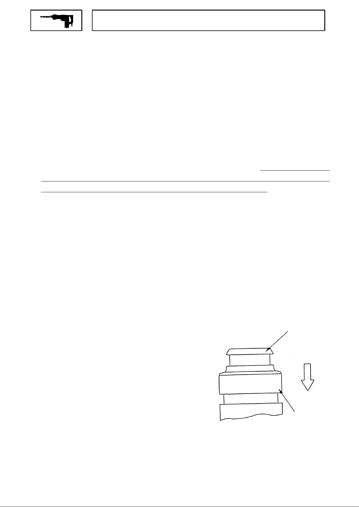
(1) Disassembly of the Striking Mechanism Section
numbers in the descriptions below correspond to the item numbers in the Parts List and exploded
With a drill bit or screwdriver bit, push in the Second Hammer
*
O-Ring RPM810
Set the Change Lever
*
[7]
, insert a small slotted-head screwdriver into the concave position located on the rear end of the Change
Lever
*
*
*
[13]
, and pull it off. (It is very important to ensure that the Change Lever
between the "Drill"and "Hammer"marks when it is disassembled or assembled.)
Loosen the four Tapping Screws D5 x 35
the Housing
[47]
to be pulled out at the same time, c aus ing dam age to the Carbon Brushes
Remove Spring (B)
Piston
[40]
mounted on it can be removed from the Inner Cover
With a bearing puller (the Special Repair Tool J-30 Bearing Puller Ass'y, Code No. 970804, is
recommended), remove the First Gear
Bearing
the 9 mm diameter end of the Second Shaft
[30]
can then be disconnected fr om the Piston Pin
[40]
[27]
.
[13]
to a position halfway between the "Drill" and"Hammer"marks on the Gear Cover
[8]
, and remove the Gear Cover
[54]
are loosely fitted together. Attempting to pull them out first could cause the Arm ature Ass ' y
[34]
from the end of the Second Shaft
moves to its max imum upper pos ition (inner c over side) . The arm of the Rec iprocating Bearing
[31]
, and t he Second Shaft
[33]
as a unit.
[41]
from the Second Shaft
. At this time, carefully note that the First Gear
[35]
.
[25]
to release the Striker
[13]
is positioned halfway
[7]
. The Inner Cover
[64]
.
[35]
, and turn the Second Shaft
[35]
and the components
[35]
. Then take off the Reciprocating
[41]
must be aligned with and pre ss-fitted onto
[28]
[35]
so that the
from the
[33]
and
Move the Clutch
*
The Clutch Spring
(2) Disassembly of the Chuck Section
As shown in Fig. 10, slide the Grip
indicated by the arrow mark, and rem ove the Front Cap
The Grip
Spring
removed from the Cylinder
[2]
[4]
, Washer (B)
[38]
to the pinion side of the Second Shaft
[37]
and Washer (B)
, Ball Holder
[5]
[36]
[2]
[3]
inside the Grip
and S teel B all
[20]
.
can then be removed from the Second Shaft
in the direction
[18]
can then be
[2]
, Holder
[1]
[35]
, and pull off the O-Ring S-8
.
Fig. 10
[39]
[35]
.
Front Cap
Grip
.
[1]
[2]
−1−
(3) Disassembly of the Cy linder , Second Gear (Slip Mechanis m S ec tion) and related parts
φ
Take the Inner Cover
*
Retaining Ring for D20 Shaft
Snap Ring Pliers [Code No. 970976] is recom m ended.) Then, turn the Gear Cover
press to extrac t the Cylinder
Cylinder
Remove the Retaining Ring for D30 Shaft
[21]
O-Ring
Cylinder
970977] onto the outer circumfer ence of the O-Ring
employed to prevent idle striking, please advise customers to replace it with a new one whenever it is
disassembled.
Extract the Retaining Ring for D37 Hole
a hand press to extract the Ball Bearing
the hand press to extract the Oil Seal
with a new one whenever it is disas s em bled.
[20]
. At this time, be very careful not to los e the three Steel Balls
, Spring (A)
[27]
from the inner part of the Cylinder
[20]
. (For easy extraction of this O-Ring
[33]
off from the Gear Cover
[22]
, and Washer (A)
[6]
. (For easy removal of this retaining ring, use of Special Repair Tool J-200
[20]
from the Gear Cover
[24]
[23]
can then be removed from the Cylinder
[17]
, turn the Gear Cover
[16]
from the Gear Cover
[14]
from the Gear Cover
[7]
, and remove the entire chuck section. Extract the
[7]
upright and use a hand
[7]
. The Sleeve
from the upper part of the Cylinder
[20]
, and the Sec ond Ham mer
[27]
, fit a S pecial Repair Tool J-201 Spring Hook [Code No.
[27]
, and pull it out. see Fig. 13) As the O-Ring
[7]
[7]
[15]
can then be extracted from the
[19]
.
[20]
. The Second Gear
[20]
. Then, extract the
[25]
can be extracted from the
so that its tip portion is upward, and use
[7]
. Next, turn the Gear Cover
. Ensure that t he Oil Seal
[14]
[27]
[7]
and use
is replaced
is
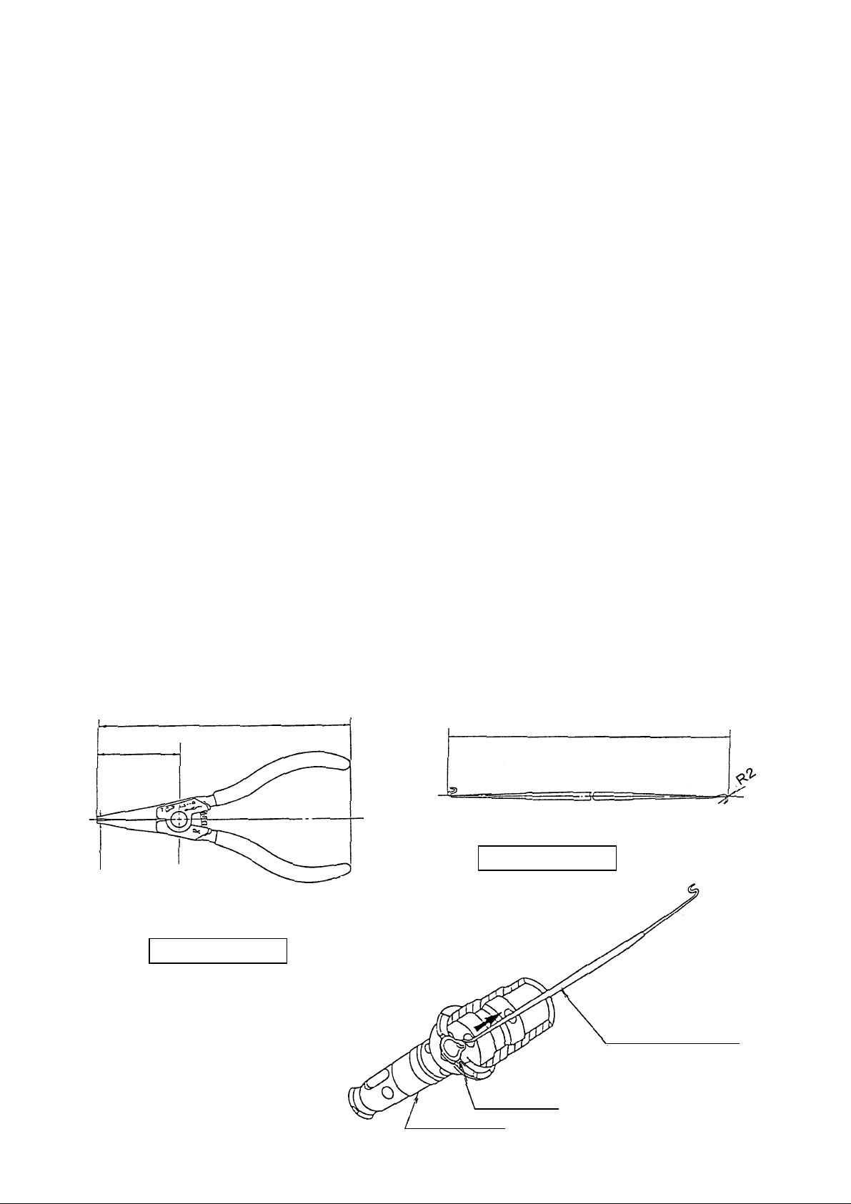
* Use of Special Repair Tools
* Snap Ring Pliers [J - 200]: (See Fig. 11)
Used to remove the Retaining Ring for D20 Shaft
[7]
Cover
* Spring Hook [J-201]: (See Fig. 12)
Used to extract the O-Ring
grip the Striker
[27]
1.2
.
[27]
inserted at the inner part of the Cylinder
[28]
to prevent idle striking. As shown in Fig. 13, fit the Spring Hook [J-201] onto the O-Ring
from its outer circ um fer enc e, and pull it out.
140
45
(1) Snap Ring Pliers (J-200)
[6]
which fixes the Cylinder
217
(2) Spring Hook
Code No. 970977
[20]
at the tip end of the Gear
[20]
which is designed to catch and
Fig. 12
Code No. 970976
Fig. 11
J-201 Spring Hook
O-Ring
Cylinder
−2−
[20]
[27]
Fig. 13

1-2. Reassembly
Perform reassembly in the rever se order of disass embly while observing the given precautions and taking care
of the following points.
(1) To make reassembly eas ier, coat grease on the Steel Balls
[10]
[14]
[13]
and Steel Ball
[11]
[13],
and then forcefully pus h the Change Lever
(2) Reassembly of the Change Lever
With a slotted-head screwdriver or s imilar tool, m ove the Clutch
that the claw (protruding portion) of the Reciprocating Bearing
[38]
Clutch
After inserting the S pring ( H)
grease to the pin portion of the Change Lever
Gear Cover
that should the mounting position of the change lever be incorrect, it will deform the claws of the c hange
lever.
(3) Reassembly of the Oil Seal
Prior to reassembly, apply grease to the inner circumference of the Oil Seal
grease to its outer circumference. Also, when press-fitting the Oil Seal
are in contact.
[7]
so that it is positioned midway between the "Hammer" mark and the " Drill" mark. Be careful
[11], [18], [19]
[38]
[40]
into the recessed portion of the Gear Cover
.
and the Recipr ocating Bearing
and the claw (protruding por tion) of the
[13]
[14]
. Howev er, do not apply
[14]
, ensure it is s traight and level.
[7]
1-3. Lubrication
Apply special grease (N.P.C. FG-6A, Code No. 980927, is recommended) to the inner and outer
[40]
so
, apply
into the
circumferences of the Piston Pin
[26]
(B)
[40]
[20]
without fail, insert 70 g (0.15 lbs.) of spec ial gr eas e ins ide the Gear Cov er
mounted on the Second Hammer
mounting portion of the Se cond Shaft
, the inner circumference of t he metal inside th e Inner Cover
[31]
and Piston
[30]
, O-Ring (A)
[25]
, the Reciproc ating Bearing
[35]
, the O-Ring
[27]
and the clutch- claw portions of the Cylinder
1-4. Tightening Torque
M4 Tapping Screws
M5 Tapping Screws
[58], [68]
[8]
............
.......................2.9 0.5 Nm (30 5 kgfcm, 26.0 4.3 in-lbs)
2.0 0.5 Nm (20 5 kgfcm, 17.4 4.3 in-lbs)
[29]
mounted on the Striker
[40]
, the Reciproc ating Bearing
[33]
and grooves of the Clutch
[7]
.
[28]
[38]
, O-Ring
. Also,
−3−

1-5. Wiring Diagram
Cord
Speed control switch
M1
1
2
C1
C2
M2
Gray White
Red Black
Stator
Stator
Fig. 14
1-6. Internal Wire Arrangement and Wiring Work
A. Internal Wire Arrangement
Reversing switch
2
1
4
3
Blue
Armature
Brown
Armature
Put the Lead wires from the stator under the Brush Holder
Push button
Brush Holder
[65]
Black (from the Stator
Brown (from the Carbon Brush
White (from the Stator
Blue (from the Carbon Brus h
Speed control switch and
reversing switch
Gray (from the Stator
Red (from the Stator
[71]
Cord
[65]
[50]
.
)
[64]
)
[50]
)
[64]
)
[50]
)
[50]
)
Fig. 15 Schematic diagra m
−4−

B. Additional Wiring Work
General inter nal wiring can be accomplished by
referring to paragraphs 9- 5 and 9- 6. The following ar e
special instructions for switc h connection.
(1) Wiring of reversing switch
Insert the lead wire (blac k ) coming from the stator
into the terminal (1) of the reversing switch, and the
lead wire (white) into the ter minal ( 2) as s hown in
Fig. 16. Insert the lead wire (brown) coming from
the carbon brush into the terminal (3) and the lead
wire (blue) into the terminal (4). A fter the insertion,
pull each lead wire slightly to check the lead wires
do not come off. To disconnect the lead wires,
insert a small slotted-head scre wdriver into the
windows near the terminals and pull out the lead
wires.
(Stator)
Black
Blue
(Carbon brush)
Fig. 16
(Carbon brush)
Brown
White
(Stator)
(Stator)
(2) Wiring of speed control switch
Insert each cord into the ter minal 1 and term inal
2 of the speed control s witc h as s hown in Fig.17
and tighten the screw (tightening torque: 0.6 0.2
Nm (6 2 kgfcm, 5.2 1.7 in-lbs)). Insert the
lead wire (gray) coming from the stator into the
terminal M1 and the lead wire (red) into the terminal
M2. After the insertion, pull eac h lead wire slightly
to check the lead wires do not come off. To
disconnect the lead wires, insert a small
slotted-head screwdriver into the windows near the
lead wires and pull out the lead wires.
1-7. Insulation Tests
On completion of reas sembly after repair, measure the insulation r esis tance and c onduct the dielectric s trength
test.
Insulation resistance : 7 MΩ or more with DC 500 V Megohm Tester
Fig. 17
Black or Br own
(Cord)
Red
White or Blue
(Cord)
(Stator)
Gray
Dielectric strength :AC 2,500 V/1 minute, with no abnormalities 110 V - 115 V
1-8. No-load Current Values
After no-load operation for 30 minutes, the no-load current values should be as follows .
Voltage (V) 110 115
Current (A) max. 3.0 3.0
−5−

2. STANDARD REPAIR TIME (UNIT) SCHEDULES
MODEL
DH24PE
Variable
Fixed
General Assembly
Fixed Cost
Switch 0 min.
Cord 10 min.
Other 20 min.
10 20
Work Flow
Speed Control
Switch
Cord
Change Lever
Armature
A'ssy
Inner Cover
O-Ring(P-22)
Ball Bearing
(608DDM)
Washer(A) x 2
Ball Bearing
(608VVM)
Front Cap
Grip
Oil Seal
Steel Ball
30
Housing
Stator
Cylinder
Steel Ball x 3
Second Gear
Spring(A)
Washer(A)
Second
Hammer
O-Ring(B)
O-Ring(FPM)
Retaining Ring
for D20
Retaining Ring
for D30
40 50
Gear Cover
Ball Bearing
(6904CM)
Retaining Ring
for D37
60 min.
Striker
O-Ring(A)
Piston
Piston Pin
Washer(C)
Spring(B)
Second Shaft
Washer(B)
Clutch Spring
Clutch
O-Ring(S8)
Reciprocating
Bearing
First Gear
Spacer
Ball Bearing
(626VVMC)
−6−
 Loading...