

Page 1
Rotary Hammer
Bohrhammer
™К˘ЪФ‰Ъ··УФ ВЪИ˜ЩЪФКИОФ
Młotowiertarka
Fúró-vésökalapács
Vrtací kladivo
Kırıcı Delici
DKoПДЛМЛpoЗaММкИ ФepЩopaЪop
DH 24PD2
Read through carefully and understand these instructions before use.
Diese Anleitung vor Benutzung des Werkzeugs sorgfältig durchlesen und verstehen.
¢И·‚¿ЫЩВ ЪФЫВОЩИО¿ О·И О·Щ·УФ‹ЫВЩВ ·˘Щ¤˜ ЩИ˜ Ф‰ЛБ›В˜ ЪИУ ЩЛ ¯Ъ‹ЫЛ.
Przed użytkowaniem należy dokładnie przeczytać niniejszą instrukcję i zrozumieć jej treść.
Használat előtt olvassa el figyelmesen a használati utasítást.
Před použitím si pečlivě přečtěte tento návod a ujistěte se, že mu dobře rozumíte.
Aleti kullanmadan önce bu kılavuzu iyice okuyun ve talimatları anlayın.
BÌËÏaÚeÎëÌo ÔpoäÚËÚe ÀaÌÌyï ËÌcÚpyÍáËï Ôo íÍcÔÎyaÚaáËË ÔpeÊÀe äeÏ ÔoÎëÁoÇaÚëcÓ ËÌcÚpyÏeÌÚoÏ.
Handling instructions
Bedienungsanleitung
√‰ЛБ›В˜ ¯ВИЪИЫМФ‡
Instrukcja obsługi
Kezelési utasítás
Návod k obsluze
Kullanım talimatları
àÌcÚpyÍáËÓ Ôo íÍcÔÎyaÚaáËË
Page 2
1
4
3
2
1
2
4
3
5
5
7
L
R
L
R
7
4
6
6
8
A
@
D
1
C
B
Page 3
9
G
10
H
B
15 mm
11
13
A
I
F
E
C
B
12
14
K
B
J
C
D
15
L
H
I
2 72
16
9
8
L
H
I
Page 4
17 18
P
Q
1
R
3
4
O
3
4
2019
S
R
T
3
Page 5

English Deutsch Ελληνικά Polski
1
Drill bit Bohrer Λεπίδα τρυπανιού
Part of SDS-plus shank
2
3
Front cap Vordere Abdeckung Μπροστιν περίβληµα
4
Grip Spannbacke Λαβή
5
Dust cup Staubschale Κύπελλο σκνης
6
Dust collector (B) Staubfänger (B) Συλλέκτης σκνης (Β)
7
Push button Druckschalter Κουµπί ώθησης
8
Change lever Wahlhebel Μοχλς αλλαγής
9
Push button Druckschalter Κουµπί ώθησης
0
Side handle Handgriff Πλευρική λαβή
A
Dust-collecting adapter Staubfangadapter
B
Hose Schlauch Μάνικα
C
Dust bag Staubsack Σάκος σκνης
Rail Strebe Οδηγς
D
E
Mounting hole Befestigungsöffnung Τρύπα στερέωσης
F
Knob on side handle Knopf oder Seitengriff Βίδα πλαϊνής λαβής
G
Attachment rod Befestigungsstab Βέργα προσαρµογής
H
Hose attachment hole
I
Dust bag attachment hole
J
Wing bolt Flügelschraube Φτερωτ µπουλνι
K
Stopper Anschlag Στπερ
L
Cap Kappe Καπάκι
M
Drill chuck Bohrfutter Σφικτήρας τρυπανιού
N
Chuck adapter Bohrfutteradapter Προσαρµογέας σφικτήρα
Chuck adapter (D) Bohrfutteradapter (D)
O
P
Bit Bohrerspitze Λεπίδα
Q
Socket Fassung Υποδοχή
Tape shank adapter Kegelschaftadapter
R
S
Cotter Dorn Κφτης
T
Rest Auflage Στήριγµα
Teii des SDS-plus Schaftes
Schlauchbefestigungsloch
Staubbeutelbefestigungsloch
Τµήµα του SDS-plus
στελέχους
Προσαρµογέας
συλλογής σκνης
Οπή προσαρµογής
µάνικας
Οπή προσαρµογής
σάκου σκνης
Προσαρµογέας
σφικτήρα (D)
Κωνικς προσαρµογέας
στελέχους
Wiertło
Część chwytu SDS-plus
Przednia pokrywa
Uchwyt
Kołnierz na pył
Pojemnik na pył (B)
Przycisk
Dźwignia nastawcza
Przycisk
Uchwyt boczny
Odpylacz
Przewód
Worek na pył
Prowadnica
Otwór mocujący
Pokrętło na uchwycie
bocznym
Pręt mocujący
Otwór zakładania
przewodu
Otwór zakładania worka
na pył
Śruba łopatkowa
Ogranicznik
Nakładka
Uchwyt wiertarski
Adaptor uchwytu
Adaptor uchwytu
narzędziowego (D)
Wiertło
Gniazdo
Adaptor uchwytu
stożkowego
Sworzeń
Oparcie
4
Page 6

Magyar Čeština Türkçe PyccÍËÈ
1
Fúróhegy Vrták
Az SDS-plusz szár része Součást dříku SDS-plus
2
3
Elülső kupak Přední kryt
4
Karmantyú Rukoje
5
Porvédő sapka Prachová miska
6
Porgyűjtő (B) Lapač prachu (B)
7
Nyomógomb Tlačítko
8
Üzemmód váltó Přeřazovací páka
9
Nyomógomb Tlačítko
0
Oldalfogantyú Boční držadlo
A
Porgyűjtő adapter Sběrný adaptér prachu
B
Tömlő Hadice
C
Porzsák Sáček na prach
D
Vezetősín Vedení
E
Vezető lyuk Upevňovací otvor
F
Gomb az oldalfogantyún
G
Rögzítőrúd Upevňovací tyč
H
Tömlőrögzítő nyílás Upevňovací otvor hadice
I
Porzsák rögzítő nyílás
J
Szárnyas csavar Křídlový šroub
K
Rögzítőgomb Zarážka
L
Sapka Krytka
M
Fúrótokmány Sklíčidlo
N
Tokmány adapter Adaptér sklíčidla
O
Tokmány adapter (D) Adaptér sklíčidla (D)
P
Korona Nástroj
Q
Befogópersely Objímka
R
Kónuszos szár adapter
S
Ék Závlačka
T
Alátámasztó blokk Klidová poloha
Tlačítko na bočním
držadle
Upevňovací otvor sáčku
na prach
Adaptér pro kuželovou
stopku
Matkap ucu
SDS-plus ßank parças˙
Ön mandren kapaåı
Kabza
Tozluk
Toz toplay˙c˙ (B)
Basma düåmesi
Deåißtirme kolu
Basma düåmesi
Yan kol
Toz toplama adaptörü
Hortum
Toz torbası
Ray
Montaj deliåi
Yan kol kontrol düåmesi
Baålantı çubuåu
Hortum takma deliåi
Toz torbası takma deliåi
Kelebek baßlı cıvata
Durdurma düåmesi
Kapakçık
Ek Mandren
Mandren adaptörü
Mandren adaptörü (D)
Uç
Soket
Konik sap adaptörü
Kama
Destekler
CÇepÎo
óacÚë xÇocÚoÇËÍa
SDS-plus
èepeÀÌËÈ ÔaÚpoÌ
ÂaÊËÏ
èêÎeÁaçËÚÌaÓ ÏaÌÊeÚa
èêÎeyÎoÇËÚeÎë (B)
HaÊËÏÌaÓ ÍÌoÔÍa
PêäaÖ ÔepeÍÎïäeÌËÓ
HaÊËÏÌaÓ ÍÌoÔÍa
ÅoÍoÇaÓ pyÍoÓÚÍa
èêÎeyÎaÇÎËÇaïçaÓ
МaАcЪaЗНa
тОaМЦ
икОecДopМкИ ПeеoН
HaФpaЗОУпзaУ
мcЪaМoЗoдМoe
oÚÇepcÚËe
PyäÍa Ìa ÄoÍoÇoÈ
pyÍoÓÚÍe
HacaÀoäÌêÈ cÚepÊeÌë
OÚÇepcÚËe ÀÎÓ
ÔpËÍpeÔÎeÌËÓ åÎaÌÖa
OÚÇepcÚËe ÀÎÓ
ÔpËÍpeÔÎeÌËÓ
ÔêÎecÄopÌoÖo ÏeåÍa
ЕapaеНoЗкИ ДoОЪ
CЪoФop
ВaЦОyеНa
ВaКЛПМкИ ФaЪpoМ
cÇepÎa
HacaÀÍa ÁaÊËÏÌoÖo
ÔaÚpoÌa
AÀaÔÚep ÁaÊËÏÌoÖo
ÔaÚpoÌa (D)
HacaÀÍa
ÉÌeÁÀo
KoÌycooÄpaÁÌaÓ ÌacaÀÍa
cÚepÊÌÓ ËÌcÚpyÏeÌÚa
KÎËÌ
èoÀcÚaÇÍa
5
Page 7

English
GENERAL OPERATIONAL PRECAUTIONS
WARNING! When using electric tools, basic safety
precautions should always be followed to reduce the
risk of fire, electric shock and personal injury, including
the following.
Read all these instructions before operating this product
and save these instructions.
For safe operations:
1. Keep work area clean. Cluttered areas and benches
invite injuries.
2. Consider work area environment. Do not expose
power tools to rain. Do not use power tools in
damp or wet locations. Keep work area well lit.
Do not use power tools where there is risk to cause
fire or explosion.
3. Guard against electric shock. Avoid body contact
with earthed or grounded surfaces (e.g. pipes,
radiators, ranges, refrigerators).
4. Keep children and infirm persons away. Do not let
visitors touch the tool or extension cord. All visitors
should be kept away from work area.
5. Store idle tools. When not in use, tools should be
stored in a dry, high or locked up place, out of reach
of children and infirm persons.
6. Do not force the tool. It will do the job better and
safer at the rate for which it was intended.
7. Use the right tool. Do not force small tools or
attachments to do the job of a heavy duty tool. Do
not use tools for purposes not intended; for example,
do not use circular saw to cut tree limbs or logs.
8. Dress properly. Do not wear loose clothing or
jewelry, they can be caught in moving parts. Rubber
gloves and non-skid footwear are recommended
when working outdoors. Wear protecting hair
covering to contain long hair.
9. Use eye protection. Also use face or dust mask if
the cutting operation is dusty.
10. Connect dust extraction equipment.
If devices are provided for the connection of dust
extraction and collection facilities ensure these are
connected and properly used.
11. Do not abuse the cord. Never carry the tool by the
cord or yank it to disconnect it from the receptacle.
Keep the cord away from heat, oil and sharp edges.
12. Secure work. Use clamps or a vise to hold the work.
It is safer than using your hand and it frees both
hands to operate tool.
13. Do not overreach. Keep proper footing and balance
at all times.
14. Maintain tools with care. Keep cutting tools sharp
and clean for better and safer performance. Follow
instructions for lubrication and changing
accessories. Inspect tool cords periodically and if
damaged, have it repaired by authorized service
center. Inspect extension cords periodically and
replace, if damaged. Keep handles dry, clean, and
free from oil and grease.
15. Disconnect tools. When not in use, before servicing,
and when changing accessories such as blades,
bits and cutters.
16. Remove adjusting keys and wrenches. Form the
habit of checking to see that keys and adjusting
wrenches are removed from the tool before turning
it on.
17. Avoid unintentional starting. Do not carry a pluggedin tool with a finger on the switch. Ensure switch is
off when plugging in.
18. Use outdoor extension leads. When tool is used
outdoors, use only extension cords intended for
outdoor use.
19. Stay alert. Watch what you are doing. Use common
sense. Do not operate tool when you are tired.
20. Check damaged parts. Before further use of the
tool, a guard or other part that is damaged should
be carefully checked to determine that it will operate
properly and perform its intended function. Check
for alignment of moving parts, free running of
moving parts, breakage of parts, mounting and any
other conditions that may affect its operation. A
guard or other part that is damaged should be
properly repaired or replaced by an authorized
service center unless otherwise indicated in this
handling instructions. Have defective switches
replaced by an authorized service center. Do not
use the tool if the switch does not turn it on and off.
21. Warning
The use of any accessory or attachment, other than
those recommended in this handling instructions,
may present a risk of personal injury.
22. Have your tool repaired by a qualified person.
This electric tool is in accordance with the relevant
safety requirements. Repairs should only be carried
out by qualified persons using original spare parts.
Otherwise this may result in considerable danger
to the user.
PRECAUTIONS ON USING ROTARY HAMMER
1. Wear earplugs to protect your ears during operation.
2. Do not touch the bit during or immediately after
operation. The bit becomes very hot during
operation and could cause serious burns.
3. Before starting to break, chip or drill into a wall,
floor or ceiling, thoroughly confirm that such items
as electric cables or conduits are not buried inside.
4. Always hold the body handle and side handle of
the power tool firmly. Otherwise the counterforce
produced may result in inaccurate and even
dangerous operation.
6
Page 8
English
SPECIFICATIONS
Voltage (by areas)* (110V, 230V)
Power Input 720W*
No-load speed 0 – 1050
Full-load impact rate 0 – 4600
Capacity: concrete 3.4 – 24 mm
Weight (without cord and side handle) 2.8 kg
Dust collecting adapter
Dustbag capacity: 0.4 liters
* Be sure to check the nameplate on product as it is subject to change by areas.
STANDARD ACCESSORIES
(1) Case (Molded plastic)................................................. 1
(2) Side handle ................................................................. 1
(3) Dust collecting adapter .............................................. 1
(4) Dust bag ...................................................................... 1
OPTIONAL ACCESSORIES (sold separately)
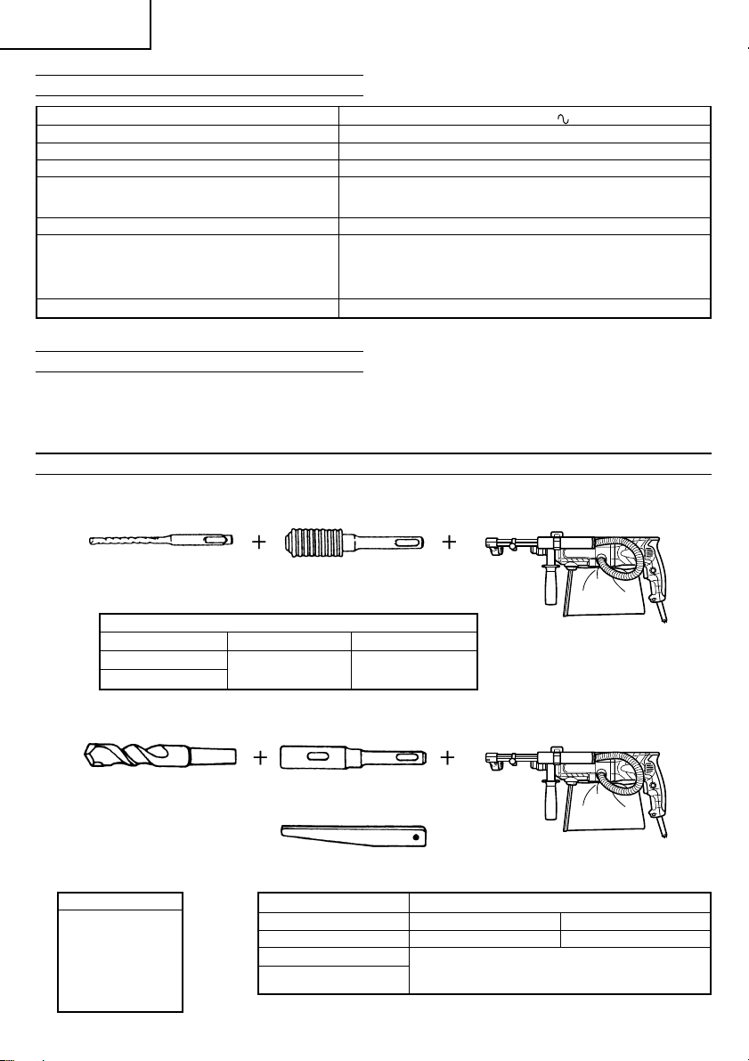
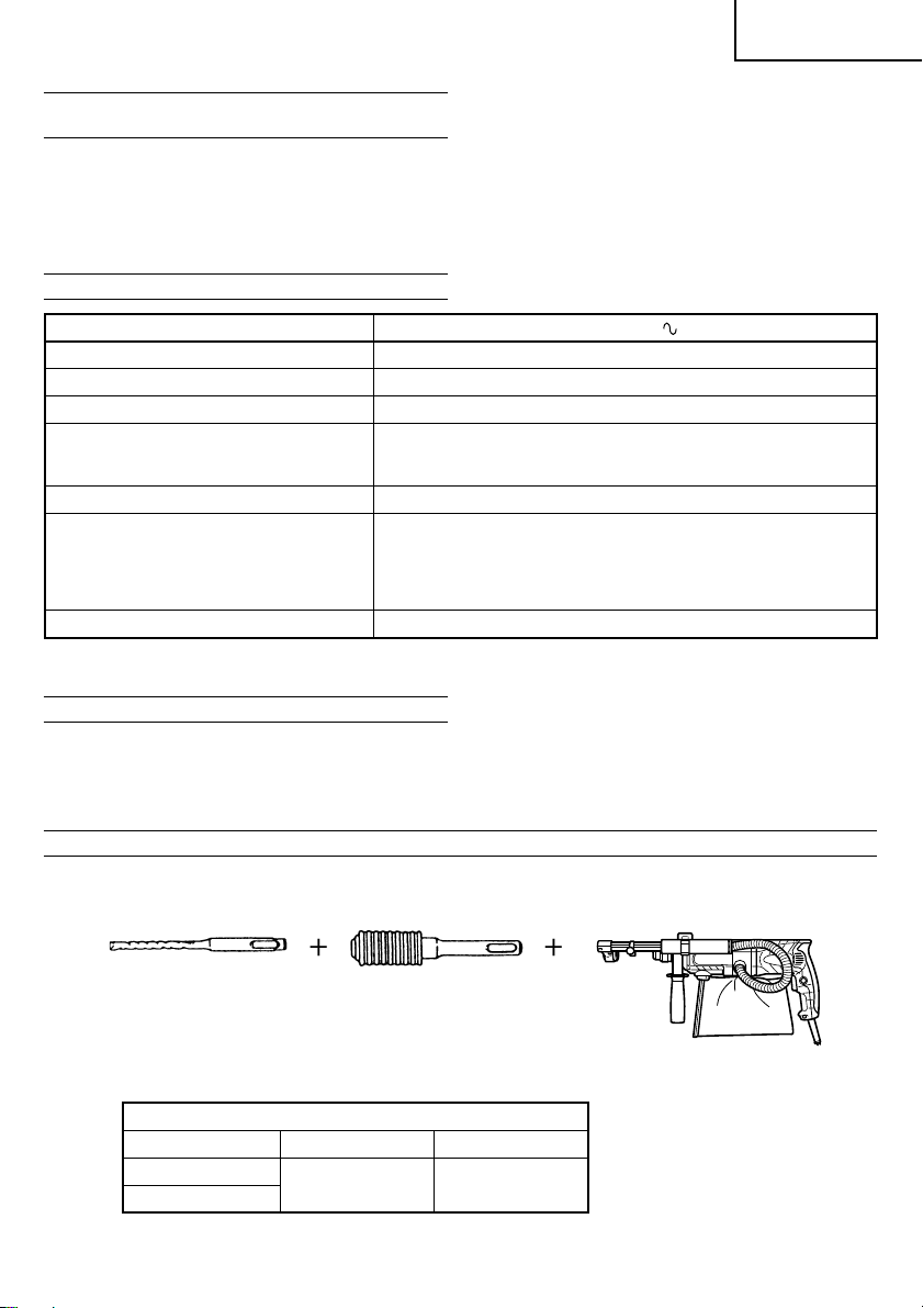
1. Drilling anchor holes (rotation + hammering)
䡬 Drill bit (Slender shaft)
steel 13 mm
wood 32 mm
Max. hole-drilling depth: 100 mm (adjustment possible between 0 and 100 mm)
Diameter of drill: 3.4 – 24 mm
Max. length of drill (overall length): 270 mm
[Numbers (3) and (4) refer to use on concrete]
(5) Cap............................................................................... 1
Standard accessories are subject to change without
notice.
min
min
–1
–1
Drill bit (Slender shaft)
Drill bit (slender shaft)
Outer diameter Effective length Overall length
3.4 mm
3.5 mm
䡬 Drill bit (Taper shank) and taper shank adapter
Drill bit (Taper shank)
Outer diameter
11.0 mm
12.3 mm
12.7 mm
14.3 mm
14.5 mm
17.5 mm
21.5 mm
7
Adapter for slender shaft
(SDS-plus shank)
45 mm 90 mm
Taper shank adapter
(SDS-plus shank)
Taper mode Applicable drill bit
Morse taper (No.1) Drill bit (taper shank) 11.0 ~ 17.5 mm
Morse taper (No.2) Drill bit (taper shank) 21.5 mm
A-taper Taper shank adapter formed A-taper or B-taper
B-taper
Cotter
is provided as an optional accessory, but the
drill bit for it is not provided.
Page 9
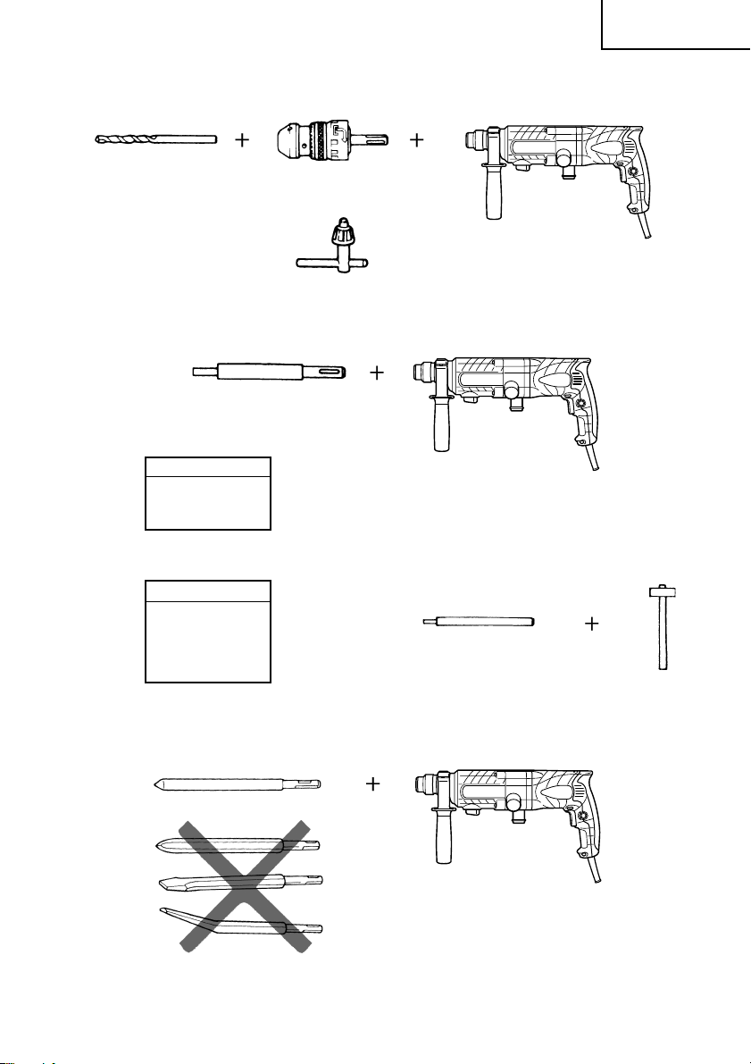
䡬 13 mm rotary hammer chuck
For drilling operations when using a straight shank bit for impact drilling with a rotary hammer.
English
Straight shank bit
( )
for impact drill
2. Anchor setting (rotation + hammering)
䡬 Anchor setting adapter (for rotary hammer)
Anchor setting adapter (SDS-plus shank)
(for rotary hammer)
Overall length: 160, 260 mm
Anchor size
W1/4”
W5/16”
W3/8”
䡬 Anchor setting adapter (for manual hammer)
Anchor size
W1/4”
W5/16”
W3/8”
W1/2”
W5/8”
13 mm rotary hammer chuck
(SDS-plus shank)
Chuck wrench
Anchor setting adapter
(for manual Hammer)
3. Demolishing operation (rotation + hammering)
Bull point (Round type only)
(SDS-plus shank)
8
Page 10

English
4. Bolt placing operation with Chemical Anchor (rotation + hammering)
Standard socket
( )
on the market
5. Drilling holes and driving screws (rotation only)
䡬 Drill chuck, chuck adapter (G), special screw and chuck wrench
6. Drilling holes (rotation only)
Drill chuck (13VLD-D)
Chuck wrench
䡬 13 mm drill chuck ass’y (includes chuck wrench) and chuck (for drilling in steel or wood).
7. Driving Screws (rotation only)
12.7 mm Chemical Anchor Adapter
19 mm Chemical Anchor Adapter
Drill chuck (13VLRB-D)Special screw
Chuck wrench
(SDS-plus shank)
Chuck adapter (G)
(SDS-plus shank)
Chuck adapter (D)
(SDS-plus shank)
Bit No.
9
Chuck adapter (D)
(SDS-plus shank)
Bit No. Screw Size Length
No. 2 3 – 5 mm 25 mm
No. 3 6 – 8 mm 25 mm
Page 11
English
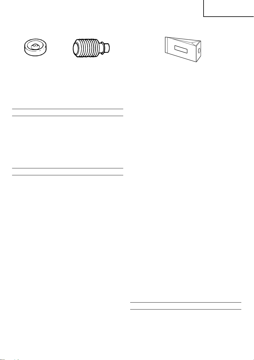
8. Dust cup, Dust collector (B)
Dust cup
10. Hammer grease A
500 g (in a can)
70 g (in a green tube)
30 g (in a green tube)
Optional accessories are subject to change without notice.
Dust collector (B)
APPLICATIONS
Rotation and hammering function
䡬 Drilling anchor holes
䡬 Drilling holes in concrete
䡬 Drilling holes in tile
Rotation only function
䡬 Drilling in steel or wood
(with optional accessories)
䡬 Tightening machine screws, wood screws
(with optional accessories)
PRIOR TO OPERATION
1. Power source
Ensure that the power source to be utilized conforms
to the power requirements specified on the product
nameplate.
2. Power switch
Ensure that the power switch is in the OFF position. If
the plug is connected to a power receptacle while the
power switch is in the ON position, the power tool
will start operating immediately, which could cause a
serious accident.
3. Extension cord
When the work area is removed from the power
source, use an extension cord of sufficient thickness
and rated capacity. The extension cord should be
kept as short as practicable.
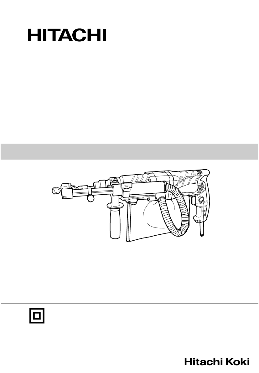
4. Mounting the drill bit (Fig. 1)
CAUTION:
To prevent accidents, make sure to turn the switch
off and disconnect the plug from the receptacle.
NOTE:
When using tools such as bull points, drill bits, etc.,
make sure to use the genuine parts designated by
our company.
(1) Clean the shank portion of the drill bit.
(2) Insert the drill bit in a twisting manner into the tool
holder until it latches itself (Fig. 1).
(3) Check the latching by pulling on the drill bit.
(4) To remove the drill bit, fully pull the grip in the
direction of the arrow and pull out the drill bit (Fig. 2).
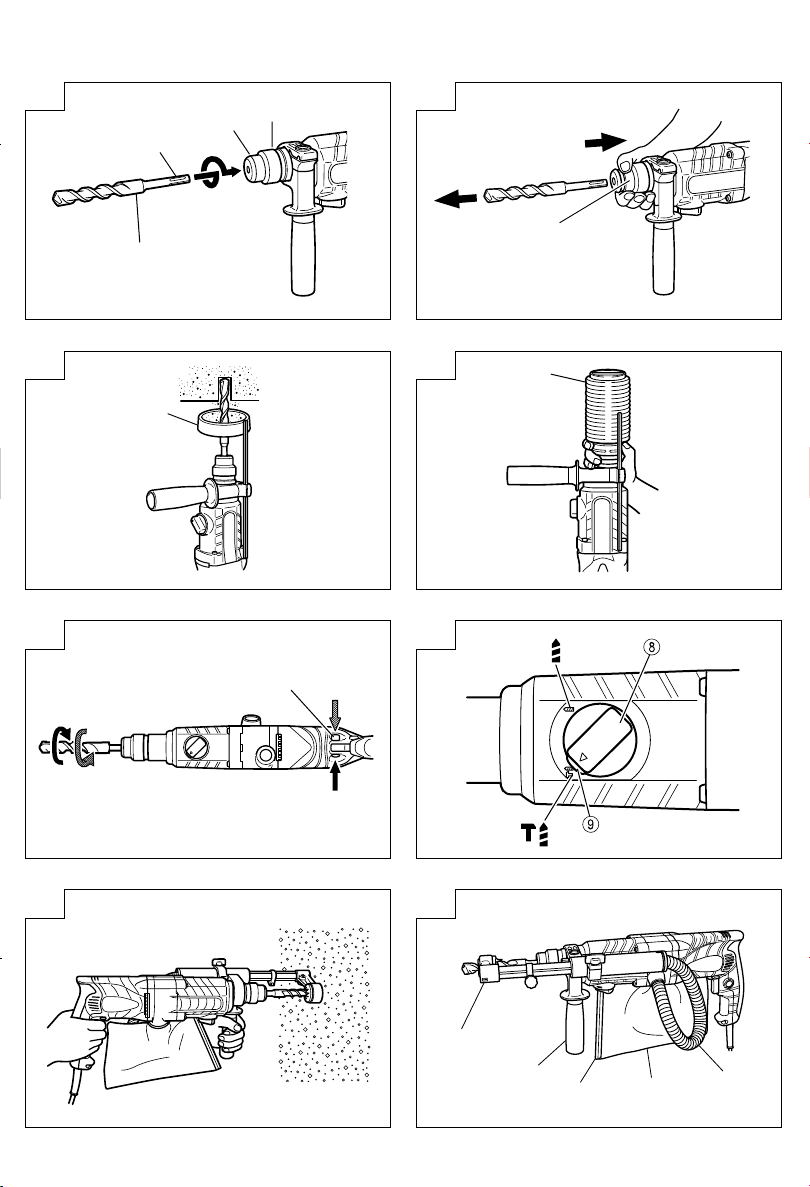
5. Installation of dust cup or dust collector (B)
(Optional accessories) (Fig. 3, Fig. 4)
When using a rotary hammer for upward drilling
operations attach a dust cup or dust collector (B) to
collect dust or particles for easy operation.
9. Paper dust bag
䡬 Installing the dust cup
Use the dust cup by attaching to the drill bit as shown
in Fig. 3.
When using a bit which has big diameter, enlarge the
center hole of the dust cup with this rotary hammer.
䡬 Installing dust collector (B)
When using dust collector (B), insert dust collector
(B) from the tip of the bit by aligning it to the groove
on the grip (Fig. 4).
CAUTION:
䡬 The dust cup and dust collector (B) are for exclusive
use of concrete drilling work. Do not use them for
wood or metal drilling work.
䡬 Insert dust collector (B) completely into the chuck
part of the main unit.
䡬 When turning the rotary hammer on while dust
collector (B) is detached from a concrete surface,
dust collector (B) will rotate together with the drill bit.
Make sure to turn on the switch after pressing the
dust cup on the concrete surface. (When using dust
collector (B) attached to a drill bit that has more than
190 mm of overall length, dust collector (B) cannot
touch the concrete surface and will rotate. Therefore
please use dust collector (B) by attaching to drill bits
which have 166 mm, 160 mm, and 110 mm overall
length.)
䡬 Dump particles after every two or three holes when
drilling.
䡬 Please replace the drill bit after removing dust
collector (B).
6. Selecting the driver bit
Screw heads or bits will be damaged unless a bit
appropriate for the screw diameter is employed to
drive in the screws.
7. Confirm the direction of bit rotation (Fig. 5)
The bit rotates clockwise (viewed from the rear side)
by pushing the R-side of the push button.
The L-side of the push button is pushed to turn the bit
counterclockwise.
HOW TO USE
CAUTION:
To prevent accidents, make sure to turn the switch
off and disconnect the plug from the receptacle when
the drill pits and other various parts are installed or
removed. The power switch should also be turned
off during a work break and after work.
10
Page 12

English
1. Switch operation
The rotation speed of the drill bit can be controlled
steplessly by varying the amount that the trigger
switch is pulled. Speed is low when the trigger switch
is pulled slightly and increases as the switch is pulled
more. Continuous operation may be attained by
pulling the trigger switch and depressing the stopper.
To turn the switch OFF, pull the trigger switch again
to disengage the stopper, and release the trigger
switch to its original position.
2. Rotation + hammering
This rotary hammer can be set to rotation and
hammering mode by pressing the push button and
turning the change lever to the
(1) Mount the drill bit.
(2) Pull the trigger switch after applying the drill bit tip to
the drilling position (Fig. 7).
(3) Pushing the rotary hammer forcibly is not necessary
at all. Pushing slightly so that drill dust comes out
gradually is sufficient.
CAUTION:
When the drill bit touches construction iron bar, the
bit will stop immediately and the rotary hammer will
react to revolve. Therefore grip the side handle and
handle tightly as shown in Fig. 7.
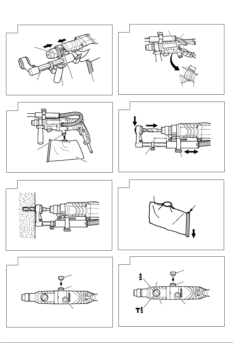
3. Using the dust-collecting adapter and dust bag
Using this unit with the dust-collecting adapter and
dust bag attached creates a more hygienic working
environment free of flying dust. Attach as shown in
Fig. 8. The unit can be used as an ordinary rotary
hammer when the dust-collecting adapter and dust
bag are not attached.
(1) Attaching the dust-collecting adapter and the dust
bag.
a) Attaching the dust-collecting adapter.
Loosen the knob on the side handle and insert the
attachment rod on the dust-collecting adapter in
the mounting hole.
The adapter can be inserted from either direction
A or B (see Fig. 9). Insert and push in the hose in
the hose attachment hole of the main unit until it
reaches the inner surface (depth 15 mm) and
confirm that it is firmly fixed (see Fig. 10).
b) Attaching the dust bag.
Insert the dust bag firmly in the dust bag
attachment hole on the main unit and fasten
securely (see Fig. 11).
CAUTION
䡬 The dust-collecting adapter and dust bag is made
for use when drilling concrete. Do not use for
drilling holes in metal or wood.
(2) Adjusting the dust-collecting adapter.
a) Adjusting the position of the dust-collecting
adapter.
After firmly inserting the drill bit, loosen the wing
bolt and drill bit tip and the end of the dustcollecting adapter in contact with each other (see
Fig. 12).
b) Setting the hole-drilling depth.
Move the stopper to determine the stroke. The
stroke is the hole-drilling depth (see Fig. 12).
䡬 The maximum hole-drilling depth when using the
dust-collecting adapter is 100 mm.
mark (Fig. 6).
䡬 It is possible when using the dust-collecting
adapter to use HITACHI drill bits up to a overall
length of 216 mm. A hole-drilling depth of 45 mm
will allow dust-collecting when the overall length
of the drill bit is 116 mm.
(3) Drilling holes
When drilling holes, secure the main unit so that the
end of the dust-collecting adapter contacts with the
concrete surface perfectly during drilling. Dustcollecting effectiveness is reduced if the adapter is
not in contact with the surface (see Fig. 13).
(4) Removing dust
Excessive dust in the dust bag will reduce dustcollecting effectiveness. Remove dust from the dust
bag regularly.
Remove the dust bag from the main unit, pull out the
rail and throw away the dust and clean (see Fig. 14).
4. When not using the dust-collecting adapter
When removing the dust-collecting adapter and the
dust bag to use as a normal rotary hammer, insert
the provided cap in the hose attachment hole. (see
Fig. 15). After removing the dust bag, the air blowing
out from the attachment hole is reduced and no air
will blow onto your face.
5. Rotation only
Remove the dust-collecting adapter as it cannot be
used. Insert the provided cap in the hose attachment
hole.
This rotary hammer can be set to rotation only mode
by pussing the push button and turning the change
lever to the
To drill wood or metal material using the drill chuck
and chuck adapter (optional accessories), proceed as
follows.
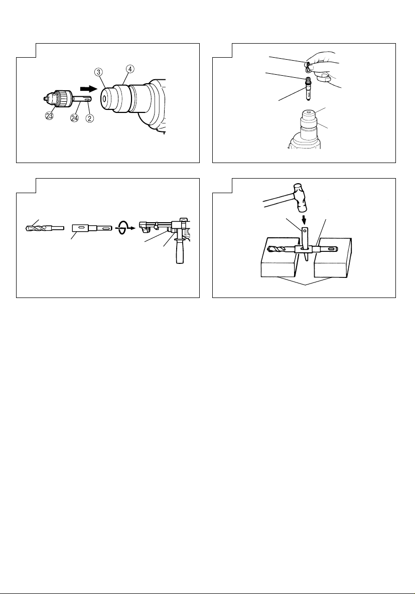
Installing drill chuck and chuck adapter: (Fig. 17)
(1) Attach the drill chuck to the chuck adapter.
(2) The part of the SDS-plus shank is the same as the
drill bit. Therefore, refer to the item of “Mounting the
drill bit” for attaching it.
CAUTION:
䡬 Application of force more than necessary will not
only expedite the work, but will deteriorate the tip
edge of the drill bit and reduce the service life of the
rotary hammer in addition.
䡬 Drill bits may snap off while withdrawing the rotary
hammer from the drilled hole. For withdrawing, it is
important to use a pushing motion.
䡬 Do not attempt to drill anchor holes or holes in
concrete with the machine set in the rotation only
function.
䡬 Do not attempt to use the rotary hammer in the
rotation and striking function with the drill chuck and
chuck adapter attached. This would seriously shorten
the service life of every component of the machine.
6. When driving machine screws (Fig. 18)
First, insert the bit into the socket in the end of chuck
adapter (D).
Next, mount chuck adapter (D) on the main unit
using procedures described in 4 (1), (2), (3), put the
tip of the bit in the slots in the head of the screw,
grasp the main unit and tighten the screw.
CAUTION:
䡬 Exercise care not to excessively prolong driving time,
otherwise, the screws may be damaged by excessive
force.
mark (Fig. 16).
11
Page 13

English
䡬 Apply the rotary hammer perpendicularly to the screw
head when driving the screw; otherwise, the screw
head or bit will be damaged, or driving force will not
be fully transferred to the screw.
䡬 Do not attempt to use the rotary hammer in the
rotation and striking function with the chuck adapter
and bit attached.
7. When driving wood screws (Fig. 18)
(1) Selecting a suitable driver bit.
Employ plus-head screws, if possible, since the driver
bit easily slips off the heads of minus-head screws.
(2) Driving in wood screws.
䡬 Prior to driving in wood screws, make pilot holes
suitable for them in the wooden board. Apply the bit
to the screw head grooves and gently drive the screws
into the holes.
䡬 After rotating the rotary hammer at low speed for a
while until the wood screw is partly driven into the
wood, squeeze the trigger more strongly to obtain
the optimum driving force.
CAUTION:
Exercise care in preparing a pilot hole suitable for the
wood screw taking the hardness of the wood into
consideration. Should the hole be excessively small
or shallow, requiring much power to drive the screw
into it, the thread of the wood screw may sometimes
be damaged.
8. How to use the drill bit (taper shank) and the taper
shank adapter
(1) Mount the taper shank adapter to the rotary hammer
(Fig. 19).
(2) Mount the drill bit (taper shank) to the taper shank
adapter (Fig. 19).
(3) Turn the switch ON, and drill a hole in prescribed
depth.
(4) To remove the drill bit (taper shank), insert the cotter
into the slot of the taper shank adapter and strike the
head of the cotter with a hammer supporting on a
rests (Fig. 20).
LUBRICATION
Low viscosity grease is applied to this rotary hammer so
that it can be used for a long period without replacing
the grease. Please contact the nearest service center for
grease replacement when any grease is leaking form
loosened screw.
Further use of the rotary hammer with lock off grease
will cause the machine to seize up reduce the service life.
CAUTION:
A special grease is used with this machine, therefore,
the normal performance of the machine may be badly
affected by use of other grease. Please be sure to let
one of our service agents undertake replacement of
the grease.
MAINTENANCE AND INSPECTION
1. Inspecting the drill bits
Since use of a dull tool will cause motor
malfunctioning and degraded efficiency, replace the
drill bit with new ones or resharpen them without
delay when abrasion is noted.
2. Inspecting the mounting screws
Regularly inspect all mounting screws and ensure
that they are properly tightened. Should any of the
screws be loose, retighten them immediately. Failure
to do so could result in serious hazard.
3. Maintenance of the motor
The motor unit winding is the very ”heart” of the
power tool. Exercise due care to ensure the winding
does not become damaged and/or wet with oil or
water.
4. Inspecting the carbon brushes
For your continued safety and electrical shock
protection, carbon brush inspection and replacement
on this tool should ONLY be performed by a Hitachi
Authorized Service Center.
5. Replacing supply cord
If the supply cord of Tool is damaged, the Tool must
be returned to Hitachi Authorized Service Center for
the cord to be replaced.
6. Service parts list
A: Item No.
B: Code No.
C: No. Used
D: Remarks
CAUTION:
Repair, modification and inspection of Hitachi Power
Tools must be carried out by a Hitachi Authorized
Service Center.
This Parts List will be helpful if presented with the
tool to the Hitachi Authorized Service Center when
requesting repair or other maintenance.
In the operation and maintenance of power tools, the
safety regulations and standards prescribed in each
country must be observed.
MODIFICATION:
Hitachi Power Tools are constantly being improved
and modified to incorporate the latest technological
advancements.
Accordingly, some parts (i.e. code numbers and/or
design) may be changed without prior notice.
NOTE:
Due to HITACHI’s continuing program of research and
development, the specifications herein are subject to
change without prior notice.
Information concerning airborne noise and vibration
The measured values were determined according to
EN60745.
The typical A-weighted sound pressure level: 90 dB (A).
The typical A-weighted sound power level: 103 dB (A).
Wear ear protection.
The typical weighted root mean square acceleration
value: 8.6 m/s2.
12
Page 14

Deutsch
ALLGEMEINE VORSICHTSMASSNAHMEN
WARNUNG! Bei der Verwendung von Elektrowerkzeugen
müssen immer die grundlegenden Vorsichtsmaßnahmen
befolgt werden, um das Risiko von Feuer, elektrischem
Schlag und persönlicher Verletzung und den
nachfolgenden Punkten zu vermeiden.
Lesen Sie diese Anweisungen völlig, bevor Sie dieses
Erzeugnis verwenden, und bewahren Sie diese
Anweisungen auf.
Für sicheren Betrieb:
1. Der Arbeitsplatz sollte sauber gehalten werden.
Unaufgeräumte Arbeitsplätze und Werkbänke
erhöhen die Unfallgefahr.
2. Die Betriebsbedingungen beachten. Elektrowerkzeuge
sollten nicht dem Regen ausgesetzt werden. Ebenfalls
sollten Sie nicht an feuchten oder nassen Plätzen
gebraucht werden. Der Arbeitsplatz sollte gut
beleuchtet sein.
Verwenden Sie Elektrowerkzeuge nicht an Orten,
an denen die Gefahr von Feuer oder Explosion
besteht.
3. Schutzmaß nahmen gegen elektrische Schläge
treffen. Darauf achten, daß das Gehäuse nicht in
Kontakt mit geerdeten Flachen kommt (z.B. Rohre,
Radiatoren, Elektroherde, Kühlschränke).
4. Kinder und gebrechliche Personen sollten vom Gerät
ferngehalten werden. Andere Personen nicht mit
dem Werkzeug oder dem Verlängerungskabel in
Kontakt kommen lassen. Besucher sollten vom
Arbeitsbereich ferngehalten werden.
5. Nicht benutzte Werkzeuge sollten sicher aufbewahrt
werden. Sie sollten an einem trockenen und
hochgelegenen oder verschließbaren Ort
aufbewahrt werden, außerhalb der Reichweite von
Kindern und gebrechlichen Personen.
6. Werkzeuge sollten nicht mit übermäßiger Gewalt
verwendet werden. Ihre Leistung ist besser und
sicherer, wenn sie mit der vorgeschriebenen
Geschwindigkeit verwendet werden.
7. Nur die korrekten Werkzeuge verwenden. Niemals
ein kleineres Werkzeug oder Zusatzgerat für
Arbeiten verwenden, die Hochleistungsgerate
erfordern. Nur Werkzeuge verwenden, die dem
Verwendungszweck entsprechen, d.h. niemals eine
Kreissäge zum Sägen von Ästen oder
Baumstämmen verwenden.
8. Die richtige Kleidung tragen. Keine lose Kleidung
oder Schmuck tragen, da sich lose Kleidungsstücke
in den bewegenden Teilen verfangen können. Bei
Arbeiten im Freien sollten Gummihandschuhe und
rutschfeste Schuhe getragen werden. Tragen Sie
eine schützende Haarabdeckung, um langes Haar
zurückzuhalten.
9. Es sollte eine Sicherheitsbrille getragen werden.
Bei Arbeiten mit Staubentwicklung sollte eine
Gesichtsoder Staubmaske getragen werden.
10. Schließen Sie eine Staubabsaugvorrichtung an.
Wenn Vorrichtungen für den Anschluß von
Staubabsaug- und -sammelvorrichtungen
vorhanden sind, so stellen Sie sicher, daß diese
angeschlossen sind und richtig verwendet werden.
11. Niemals das Kabel mißbrauchen. Ein Werkzeug
niemals am Kabel tragen oder bei Abtrennung von
der Steckdose das Kabel harausreißen. Das Kabel
sollte gegen Hitze, Öl und scharfe Kanten geschützt
werden.
12. Den Arbeitsplatz gut absichern. Zwingen oder einen
Schraubstock zur Befestigung des Werkstücks
verwenden. Das ist sicherer als die Benutzung der
Hände und macht beide Hände zur Bedienung des
Werkzeugs frei.
13. Sich niemals weit überbeugen. Immer einen festen
Stand und ein sicheres Gleichgewicht bewahren.
14. Die Werkzeuge sollten sorgfältig behandelt werden.
Für einen einwandfreien und sicheren Betrieb sollten
sie stets scharf sein und saubergehalten werden.
Die Anleitungen für schmierung und Austausch des
Zuehörs unbedingt einhalten. Die Kabel der Geräte
regelmäßig überprüfen und bei Beschädigung durch
eine autorisierte Kundendienststelle reparieren
lassen. Ebenfalls die Verlägerungskabel regelmäßig
überprüfen und bei Beschadigung auswechseln. Die
Handgriffe sollten stets trocken und sauber sein,
sowie keine Öl- oder Schmierfett stellen aufweisen.
15. Werkzeuge vom Netz trennen, wenn sie nicht
benutzt werden, vor Wartungsarbeiten und beim
Austausch von Zubehörteilen wie z.B. Blätter, Bohrer
und Messer.
16. Alle Stellkeile und Schraubenschlüssel entfernen.
Vor Einschaltung des Gerätes darauf achten, daß
alle Stellkeile und Schraubenschlüssel entfernt
worden sind.
17. Ein unbeabsichtigtes Einschalten sollte vermieden
werden. Niemals ein angeschlossenes Werkzeug
mit dem Finger am Schalter tragen. Vor Anschluß
überprüfen, ob das Gerät ausgeschaltet ist.
18. Im Freien ein Verlängerungskabel verwenden. Nur
ein Verlängerungskabel verwenden, das für die
Verwendung im Freien markiert ist.
19. Den Arbeitsvorgang immer unter Kontrolle haben.
Das Gerät niemals in einem abgespannten Zustand
verwenden.
20. Beschädigte Teile überprüfen. Vor Benutzung des
Werkzeugs sollten beschädigte Teile oder
Schutzvorrichtungen sorgfältig überprüft werden,
um festzustellen, ob sie einwandfrei funktionieren
und die vorgesehene Funktion erfüllen, Ausrichtung,
Verbindungen sowie Anbringung sich bewegender
Teile überprüfen. Ebenfalls uberprufen, ob Teile
gebrochen sind. Teile oder Schutzvorrichtungen,
die beschädigt sind, sollten, wenn in dieser
Bedienungsanleitung nichts anderes erwähnt ist,
durch eine autorisierte Kundendienststelle ausge
wechselt oder repariert werden. Dasselbe gilt für
defekte Schalter. Wenn sich das Werkzeug nicht
mit dem Schalter einoder ausschalten läßt, sollte
das Werkzeug nicht verwendet werden.
21. Warnung
Die Verwendung von anderem Zubehör oder
anderen Zusätzen als in dieser Bedienungsanleitung
empfohlen kann das Risiko einer Körperverletzung
einschließen.
22. Lassen Sie Ihr Werkzeug durch qualifiziertes Personal
reparieren.
Dieses Elektrowerkzeug entspricht den zutreffenden
Sicherheitsanforderungen. Reparaturen sollten nur
von qualifiziertem Personal unter Verwendung von
Originalersatzteilen durchgeführt werden, da sonst
beträchtliche Gefahr für den Benutzer auftreten kann.
13
Page 15
Deutsch
VORSICHTSMASSNAHMEN BEI BENUTZUNG
DES BOHRHAMMERS
1. Ohrenstöpsel zum Schutz der Ohren während des
Betriebs tragen.
2. Die Bohrerspitze während oder unmittelbar nach dem
Betrieb nicht berühren. Die Bohrerspitze wird während
des Betriebs sehr heiß, sobaß es zu ernsthaften
Verbrennungen führen könnte.
3. Bevor man on der Wand, im Boden oder an der
Decke etwas ausbricht, meißelt oder bohrt, muß man
sich sorgfältig davon überzeugen, ob keine
elektrischen Kabel oder Kabelrohre darunter liegen.
4. Immer den körper-Handgriff und Seiten-Handgriff des
Elektrowerkzeugs festhalten, weil die entstehende
Gegenkraft sonst zu einem ungenauen und
gefährlichen Arbeiten führt.
TECHNISCHE DATEN
Spannung (je nach Gebiet)* (110V, 230V)
Leistungsaufnahme 720W*
–1
Leerlaufdrehzahl 0 – 1050
Vollastschlagzahl 0 – 4600 min
Kapazität: Beton 3,4 – 24 mm
Gewicht (ohne Kabel und Handgriff) 2,8 kg
Staubfangadapter
Staubbeutelfassungsvermögen 0,4 Liter
* Vergessen Sie nicht, die Produktangaben auf dem Typenschild zu überprüfen, da sich diese je nach Verkaufsgebiet
ändern.
Stahl 13 mm
Holz 32 mm
Max. Lochbohrtiefe: 100 mm (zwischen 0 und 100 mm verstellber)
Bohrerdurch messer: 3,4 – 24 mm
Max. Länge der Bohrspitze: 270 mm
(Gesamtlänge)
min
–1
STANDARDZUBEHÖR
(1) Tasche (Plastk) ............................................................1
(2) Handgriff ..................................................................... 1
(3) Staubfangadapter ....................................................... 1
(4) Staubsak ...................................................................... 1
[Nummer (3) und (4) beziehen sich auf die Verwendung
Beton]
(5) Kappe .......................................................................... 1
Das Standardzubehör kann ohne vorherige
Bekanntmachung jederzeit geändert werden.
SONDERZUBEHÖR (separat zu beziehen)
1. Bohren von Ankerlöchern (Drehen und Hämmern)
䡬 Bohrer (dünner Schaft)
Bohrer (dünner Shaft)
Bohrer (dünner Schaft)
Außendurchmesser Arbeitslänge Gesamtlänge
3,4 mm
3,5 mm
Adapter für dünnen Schaft
(SDS-Plus Schaft)
45 mm 90 mm
14
Page 16
Deutsch
䡬 Bohrer (Kegelschaft) und Konusschaftadapter
Bohrer (Kegelschaft)
Außendurchmesser
11,0 mm
12,3 mm
12,7 mm
14,3 mm
14,5 mm
17,5 mm
21,5 mm
䡬 13 mm Bohrhammerfutter
Zum Bohrbetrieb mit gerader Schlagspitze für schlagbohrer mit bohrhammer.
Gerade Meißelspitze
(
für Schlagbohrer
2. Ankereinsatz (Drehen und Hämmern)
䡬 Adapter für Ankerbefestigung (mit Bohrhammer)
)
Konusschaftadapter
(SDS-Plus Schaft)
Dorn
Konusschaftadapter Anwendbarer Bohrer
Morsekonus (Nr.1) Bohrer (Konusschaft) 11,0 ~ 17,5 mm
Morsekonus (Nr.2) Bohrer (Konusschaft) 21,5 mm
A-Konus Der Konusschaftadapter in der Form des A- oder
B-Konus der passende Bohrer separat zu beziehen.
13 mm Bohrhammerfutter
(SDS-Plus Schaft)
Bohrfutterschlüssel
B-Konus wird nach Wunsch geliefert, doch ist
Adapter für Ankerbefestigung (SDS-Plus Schaft)
(mit Bohrhammer)
Gesamtlänge: 160, 260 mm
Ankergröße
W1/4”
W5/16”
W3/8”
䡬 Adapter für Ankerbefestigung (mit dem Handhammer)
Ankergröße
W1/4”
W5/16”
W3/8”
W1/2”
W5/8”
15
Adapter für Ankerbefestigung
(mit dem Handhammer)
Page 17
3. Aufbrecharbeiten (Drehen und Hämmern)
Spitzmeißel (Nur runder Typ)
(SDS-Plus Schaft)
4. Bolzenplazierung für Chemical Anchor (Drehen und Hämmern)
Deutsch
Sockel auf
( )
markierter stelle
5. Löcherbohren und schneidschraube (nur Drehung)
䡬 Bohrfutter, Bohrfutteradapter (G), Spezialschraube und Bohrfutterschlüssel
Spezialschraube
6. Löcherbohren (nur Drehung)
Bohrfutter (13VLD-D)
Bohrfutterschlüssel
䡬 Zum Bohren von Stahl oder Holz: Bohrfuttervorrichtung von 13 mm (einschl Futterschlüssel), Futteradapter.
12,7 mm Adapter für Chemical Anchor
19 mm Adapter für Chemical Anchor
Bohrfuter (13VLRB-D)
Bohrffutterschlüssel
(SDS-Plus Schaft)
Bohrfutteradapter (G)
(SDS-Plus Schaft)
Bohrfutteradapter (D)
(SDS-Plus Schaft)
16
Page 18
Deutsch
7. Schneidschraube (nur Drehung)
Bohrespitzennummer
Bohrerspitzen-
nummer
8. Staubschale, Staubfang (B)
Staubschale
10. Hammer Schmierfett A
500 g (Dose)
70 g (in grüner Tube)
30 g (in grüner Tube)
Das Sonderzubehöre kann ohne vorherige Bekanntmachung jederzeit geändert werden.
Staubfang (B)
ANWENDUNGEN
Dreh- und Hämmerfunktion
䡬 Bohren von Ankerlöchern
䡬 Bohren von Löchern in Beton
䡬 Bohren von Löchern in Kachel
Nur Drehbohrfunktion
䡬 Bohren in Stahl oder Holz (mit Sonderzubehör)
䡬 Anziehen von Maschinenschrauben, Holzschrauben
(mit Sonderzubehör)
VOR INBETRIEBNAHME
1. Netzspannung
Prüfen, daß die zu verwendende Netzspannung der
Angabe auf dem Typenschild entspricht.
2. Netzschalter
Prüfen, daß der Nezschalter auf „AUS” steht. Wenn
der Stecker an das Netz angeschlossen wird, während
der Schalter auf „EIN” steht, beginnt das Werkzeug
sofort zu laufen, was gefährlich ist.
3. Verlängerungskabel
Wenn der Arbeitsbereich nicht in der Nähe des
Netzanschlusses liegt, ist ein Verlängerungskabel
ausreichenden Querschnitts und ausreichender
Nennleistung zu verwenden. Das Verlängerungskabel
sollte so kurz wie möglich gehalten werden.
Bohrfutteradapter (D)
(SDS-Plus Schaft)
Schraubengröße Länge
Nr. 2 3 - 5 mm 25 mm
Nr. 3 6 - 8 mm 25 mm
9. Papierstaubtüte
4. Anbringen des Bohreinsatzes (Abb. 1)
ACHTUNG:
Stellen Sie zur Verhütung von Unfällen sicher, dass
der Schalter ausgeschaltet und der Stecker aus der
Steckdose gezogen ist.
HINWEIS:
Achten Sie bei der Verwendung von Werkzeugen wie
Meißeln, Bohrern usw. darauf, von unserer Firma
bezeichnete Markenteile zu verwenden.
(1) Reinigen Sie den Schaftabschnitt des Bohrers.
(2) Schieben Sie den Bohrer unter Drehung in den
Werkzeughalter ein, bis er sich verriegelt (Abb. 1).
(3) Überprüfen Sie die Verriegelung durch Ziehen am
Bohrer.
(4) Zum Entfernen des Bohrers den Griff in Pfeilrichtung
ziehen, und den Bohrer herausziehen (Abb. 2).
5. Beim Installieren der Staubschale oder des
Staubfangs (B) (Zonderzubehör) (Abb. 3, Abb. 4)
Wenn ein Bohrhammer zum Bohren nach oben ohne
Staubfangadapter verwendet wird, eine Staubkappe
oder einen Staubfang (B) zum Auffangen von Staub
und Partikeln zum leichten Betrieb anbringen.
䡬 Anbringen der Staubschale
Die Staubschale durch Anbringen an die Bohrspitze
wie in Abb. 3 gezeigt verwenden.
Bei Bohrspitzen mit großem Durchmesser das
Mittenloch der Staubschale mit diesem Bohrhammer
vergrößern.
17
Page 19

Deutsch
䡬 Anbringen des Staubfangs (B)
Bei Verwendung des Staubfangs (B) den Staubfang
(B) von der Spitze der Bohrspitze einführen, und an
die Rille an der Spitze ansetzen (Abb. 4).
ACHTUNG:
䡬 Die Staubschale und der Staubfang (B) sind nur für
Bohren in Beton gedacht. Nicht für Bohrarbeiten in
Holz oder Metall verwenden.
䡬 Den Staubfang (B) vollständig in den Futterteil der
Haupteinheit einsetzen.
䡬 Wenn am Bohrhammer gedreht wird, während die
Staubfang (B) von der Betonoberfläche abgenommen
ist, dreht sich die Staubfang (B) zusammen mit der
Bohrspitze. Immer am Schalter drehen, nachdem die
Staubschale auf die Betonoberfläche gedrückt ist.
(Bei Verwendung der Staubfang (B) durch Anbringen
einer Bohrspitze mit mehr als 190 mm Gesamtlänge
kann die Staubfang (B) nicht die Betonoberfläche
berühren und dreht sich. Darum immer Bohrspitzen
mit 166, 160 und 110 mm Gesamtlänge verwenden.)
䡬 Nach dem Bohren von zwei oder drei Löchern den
Inhalt der Staubfang (B) ausleeren.
䡬 Die Bohrspitze nach dem Abnehmen der Staubfang
(B) austauschen.
6. Wahl der Schrauberspitze
Falls die Schrauberspitze dem Schraubendurchschnitt
nicht anpassend wird, werden Schraubenkopf und
Schrauberspitze beschädigt.
7. Die Drehrichtung der Bohrerspitze prüfen (Abb. 5)
Der Bohrer dreht sich im Uhrzeigersinn (gesehen von
hinten), Wenn die R-Seite des Druckknopfs gedrückt
wird. Wenn die L-Seite des Bohrers gedrückt wird,
dreht sich der Bohrer gegen den Uhrzeigersinn.
GEBRAUCHSANWEISUNG
ACHTUNG:
Zur Verhütung von Unfällen beim Anbringen und
Entfernen von Bohrern und anderen Teilen immer
den Schalter ausschalten und den Stecker des
Netzkabels aus der Steckdose ziehen. Der Schalter
sollte auch während Arbeitsunterbrechungen und
nach der Arbeit ausgeschaltet werden.
1. Betätigung des Schalters
Die Drehzahl des Bohrers kann durch Veränderung
des Drucks auf den Drückerschalter gesteuert werden.
Die Geschwindigkeit ist gering, wenn der
Drückerschalter nur leicht gezogen ist und erhöht
sich, wenn der Schalter weiter durchgezogen wird.
Kontinuierlicher Betrieb läßt sich durch das Ziehen
des Drückerschalters und Eindrücken des
Arretierknopfes erreichen. Zum Ausschalten wird der
Drückerschalter erneut gezogen und der Arretierknopf
gelöst. Nach dem Loslassen kehrt der Drückerschalter
in seine ursprüngliche Stellung zurück.
2. Drehen und Hämmern
Dieser Bohrhammer kann durch Druck auf den
Druckknopf und Drehen des Umschalthebels zur
Markierung
werden (Abb. 6).
(1) Die Bohrerspitze anbringen.
(2) Den Triggerschalter nach Anbringen in Bohrlage der
Bohrerspitze ziehen (Abb. 7).
auf Drehen und Hämmern eingestellt
(3) Es ist nicht nötig den Bohrhammer stark anzudrücken.
Leichtes Andrücken, so daß der Bohrstaub regelmäßig
herausfällt, ist gerade genügend.
ACHTUNG:
Wenn der Bohrer mit Baueisenstangen in Berührung
kommt, stoppt sofort der Bohren, und nur der
Bohrhammer dreht sich. Deshalb den Handgriff gut
fest halten wie in Abb. 7 gezeigt.
3. Verwendung des Staubfangadapters und Staubsacks
Der Einsatz der Maschine mit Staubfangadapter und
Staubsack sorgt für eine sauberere Arbeitsumgebung,
frei von herumwirbelndem Staub. Befestigen Sie den
Staubfangbeutel wie in Abb. 8 gezeigt. Ohne
Staubfangadapter und Staubsack das Gerät als
normale Schlagbohrmaschine verwendet werden.
(1) Befestigung des Staubfangadapters und des
Staubsacks.
a) Befestigung des Staubfangadapters
Lösen Sie die Knopf am Seitenbohrer, und stecken
Sie den Befestigungsstab in das Befestigungsloch
des Staubfangadapters.
Der Adapter kann sowohl von Richtung A als auch
B (siehe Abb. 9) eingesteckt werden. Den Schlauch
in das Schlauchbefestigungsloch des Hauptgeräts
drücken, bis er die Innenfläche (Tiefe 15 mm)
erreicht und bestätigen, daß er fest sitzt (siehe
Abb. 10).
b) Ansetzen des Staubsacks
Stecken Sie den Staubsack fest in das
Befestigungsloch an der Bohrmaschine ein, und
befestigen Sie ihn (siehe Abb. 11).
VORSICHT
䡬 Der staubfangadapter und Staubsack ist für die
Verwendung beim Bohren von beton vorgesehen.
Verwenden Sie diesen deshalb nicht beim Bohren
Metall oder Holz.
(2) Einstellung des Staubfangadapters
a) Einstellung der Position des Staubfangadapters
Lösen Sie, nachdem Sie den Bohrer fest
eingesteckt haben, die Spannfutterschraube und
die Bohrerspitze und das Ende des
staubfangadapters, die sich einander berühren
(siehe Abb. 12).
b) Einstellung der Lochbohrtiefe
Versetzen Sie den Anschlag zur Festlegung des
Hubs. Der Hub ist die Lochbohrtiefe (siehe
Abb. 12).
䡬 Bei verwendung des Staubfangadapters beträgt
die maximale Lochbohrtiefe 100 mm.
䡬 Bei Verwendung des Staubfangadapters können
HITACHI Bohrer bis zu einer Gesamtänge von 216
mm verwendet werden.
Eine Lochbohrtiefe von 45 mm ermöglicht den
Staubabfang, wenn die Gesamtlänge des Bohrers
116 mm beträgt.
(3) Lochbohren
Befestigen Sie die Maschine beim Lochbohren so,
daß das Ende des Staubfangadapters während des
Bohrens fest mit der Betonfläche in Kontakt bleibt.
Die Staubfangleistung wird heraubgesetzt, wenn sich
der adapter von der Betonfläche abhebt (siehe
Abb. 13).
18
Page 20

Deutsch
(4) Staubentfernung
Übermäßige Staubansammlung im Staubfangbeutel
verringert die Staubfangleistung. Leeren Sie den
Staubfangbeutel deshalb regelmäßig aus.
Den Staubsack vom Hauptgerät abnehmen, die Strebe
abziehen und den Staub wegwerfen und säubern
(siehe Abb. 14).
4. Wenn der staubfangadapter nicht verwendet wird
Wenn Sie den Staubfangadapter und den Staubsack
abnehmen, um das Gerät als normale
Schlagbohrmaschine zu verwenden, setzen Sie die
mitgelieferte Kappe in die Bohrung für den Schlauch
ein (siehe Abb. 15). Nach dem Entfernen des
Staubsacks wird die aus dem Staubsack-Anbringloch
ausblasende Luftmenge verringert, und keine Luft
bläst in Ihr Gesicht.
5. Nur Drehbohren
Den Staubfangadapter entfernen, da er nicht
verwendet werden kann. Die Zubehörkappe auf das
Schlauchbefestigungsloch aufsetzen.
Dieser Bohrhammer kann durch Druck auf den
Druckknopf und Drehen des Umschalthebels zur
Markierung
werden (Abb. 16).
Zum Bohren von Holz und Metall einen
Bohrfutteradapter und ein Bohrfutter (zubehör)
verwenden.
Anbringung des Bohrfutters und Bohrfutteradapters:
(Abb. 17)
(1) Das Bohrfutter am Adapter anbringen.
(2) Das Teil des SDS-Plus Schaftes ist das gleiche wie
der Bohrer. Zum Anbringen deshalb auf den Punkt
„Anbringung des Bohrers” beziehen.
ACHTUNG:
䡬 Übermäßiger Druck wird nicht die Arbeit
beschleunigen und kann dazu die Bohrerleistung und
auch die Lebensdauer des Bohrhammers vermindern.
䡬 Der Bohr kann beim Herausziehen des Bohrhammers
aus der Bohrung abbrechen. Beim Herauszeihen ist
es deshalb wichtig Druckbewegung anzuwenden.
䡬 Nicht versuchen Ankerlöcher oder gewöhnliche
Löcher in Beton zu bohren, wenn das Werkzeug nur
auf Drehbohrfunktion eingestellt ist.
䡬 Nicht versuchen den Bohrhammer Schlag-und
Drehbohren zu verwenden, wenn das Bohrfutter und
der Bohrfutteradapter angebracht sind. Sonst wird
die Lebensdauer des Werkzeuges verkürzt werden.
6. Einschrauben von Maschinenschrauben (Abb. 18)
Zuerst die Drehspitze in den Sockel am Ende des
Futteradapters (D) einsetzen.
Dann den Futteradapter (D) mit dem in 4 (1), (2), (3)
beschriebenen Verfahren an die Haupteinheit
anbringen, die Spitze des Drehstücks in die Schlitze
auf dem Schraubenkopf setzen, die Haupteinheit fest
greifen und die Schrauben festziehen.
ACHTUNG:
䡬 Nicht mehr als nötig die Schraubzeit verlängern, um
Beschädigung der Schrauben zu vermeiden.
䡬 Den Bohrhammer senkrecht beim Einschrauben einer
Schraube an den Schraubenkopf ansetzen; sonst
könnte der Schraubenkopf oder die Bohrerspitze
beschüdigt werden, oder die Antriebskraft mag nicht
volkommen der Schraube übertragen werden.
auf Betrieb nur für Bohren eingestellt
䡬 Nicht versuchen, den Schlagbohrer in Schlag-Bohr-
Betriebsart zu verwenden, wenn Futteradapter und
Bohrspitze aufgesetzt sind.
7. Einschrauben von Holzschrauben (Abb. 18)
(1) Wahl einer passenden Bohrerspitze
So sehr wie möglich Kreuzkopfschrauben verwenden
da die Bohrerspitze leicht von gewöhnlichen
Schraubenköpfen abrutscht.
(2) Eischrauben
䡬 Vor dem Einschrauben von Holzschrauben, passende
Löcher im Holz orbereiten. Die Bohrerspitze an die
Schraubenkopfspalten ansetzen und die Schraube
sanft ins Holz einschrauben.
䡬 Nachdem sich der Bohrerhammer bei kleiner
Geschwindigkeit für eine Weile gedrecht hat bis die
Schraube zum Teil eingeschraubt wurde, fester auf
den Trigger drücken um optimale Antriebskraft zu
erreichen.
ACHTUNG:
Gut darauf achten, daß die Vorbereitung eines
passenden Loches für die Schraube gemäß der Härte
des Holzes durchgeführt wird. Falls das Loch zu klein
oder nicht tief genung sein sollte, und dadurch große
Kraftanwendung zum Einschrauben erforderlich wird,
kann das Schraubengewinde manchmal beschädigt
werden.
8. Benutzung des Bohrers (Kegelschafts) und des
Kegelschaftadapters
(1) Den Kegelschaftadapter am Bohrhammer anbringen
(Abb. 19).
(2) Den Bohrer (Kegelschaft) am Kegelschaftadapter
anbringen (Abb. 19).
(3) Den Schalter einschalten und ein Loch mit der
vorgegebenen Tiefe bohren.
(4) Zur Entferung des Bohrers (Kegelschafts) einen Dorn
in den Schlitz des Kegelschaftadapters einführen und
mit einem Hammer gestüzt durch eine Auflage auf
den Kopf des Dorns schlagen (Abb. 20).
SCHMIERUNG
Für diesen Bohrhammer sollte ein Schmiermittel mit
niedriger Viskositä verwendet werden, damit er über
einen längeren Zeitraum ohne Schmierfettwechsel
verwendet werden kann. Sollte Schmierfett aufgrund
gelöster Schrauben austreten, bitte für die Auswechslung
des Schmierfetts die nächstgelegene Kundendienststelle
aufsuchen.
Wird der Bohrhammer in solch einem Fall weiterverwen
det, könnte sich das Gerät festfressen, wodurch die
lebensdauer verkürtzt wird.
ACHTUNG:
Es sollten nur die vorgeschriebenen Schmiermittel
verwendet werden. Wenn andere Schmiermittel
verwendet werden, könnte die Leistung des Gerätes
beeinträchtigt werden. Wenden Sie sich bitte für die
Auswenchslun des Schmiermittels an unsere
Kundendienststelle.
19
Page 21

Deutsch
WARTUNG UND INSPEKTION
1. Inspektion des Bohrers
Fortgesetzte Verwendung eines stumpfen oder
beschädigten Bohrers führt zu verminderter
Bohrleistung und kann den Motor der Bohrmaschine
erheblich überbelasten. Den Bohrer regelmäßig
prüfen und erforderlichenfalls durch einen neuen
Bohrer ersetzen.
2. Inspektion der Befestigungsschrauben
Alle Befestigungsschrauben werden regelmäßig
inspiziert und geprüft, ob sie gut angezogen sind.
Wenn sich eine der Schrauben lockert, muß sie sofort
wieder angezogen werden. Geschieht das nicht, kann
das zu erheblichen Gefahren führen.
3. Wartung des Motors
Die Motorwicklung ist das „HERZ” des
Elektrowerkzeugs. Daher ist besonders sorgfältig
darauf zu achten, daß die Wicklung nicht beschädigt
wird und/oder mit Öl oder Wasser in Berührung
kommt.
4. Inspektion der Kohlebürsten
Zur Erhaltung Ihrer Sicherheit und des Schutzes gegen
elektrischen Schlag sollten Inspektion und
Auswechseln der Kohlebürsten NUR durch ein
Autorisiertes Hitachi-Wartungszentrum durchgeführt
werden.
5. Auswechseln des Netzkabels
Wenn das Netzkabel des Werkzeugs beschädigt wird,
muss das Werkzeug zum Auswechseln des Netzkabels
an ein von Hitachi autorisiertes Wartungszentrum
zurückgegeben werden.
6. Liste der Wartungsteile
A: Punkt Nr.
B: Code Nr.
C: Verwendete Anzahl
D: Bemerkungen
ACHTUNG:
Reparatur, Modifikation und Inspektion von HitachiElektrowerkzeugen müssen durch ein Autorisiertes
Hitachi-Wartungszentrum durchgeführt werden.
Diese Teileliste ist hilfreich, wenn sie dem
Autorisierten Hitachi-Wartungszentrum zusammen
mit dem Werkzeug für Reparatur oder Wartung
ausgehändigt wird.
Bei Betrieb und Wartung von Elektrowerkzeugen
müssen die Sicherheitsvorschriften und Normen
beachtet werden.
MODIFIKATIONEN:
Hitachi-Elektrowerkzeuge werden fortwährend
verbessert und modifiziert, um die neuesten
technischen Fortschritte einzubauen.
Dementsprechend ist es möglich, daß einige Teile
(z.B. Codenummern bzw. Entwurf) ohne vorherige
Benachrichtigung geändert werden.
Information über Betriebslärm und Vibration
Die Meßwerte wurden entsprechend EN60745 bestimmt.
Der typische A-gewichtete Schalldruckt ist 90 dB (A).
Der typische A-gewichtete Schalleistungspegel ist 103
dB (A).
Bei der Arbeit immer einen Ohrenschutz tragen.
Der typische gewogene quadratische Mittelwert für die
Beschleunigung ist 8,6 m/s2.
HINWEIS:
Aufgrund des ständigen Forschungs-und
Entwicklungsprogramms von HITACHI sind Änderungen
der hierin gemachten technischen Angaben nicht
ausgeschlossen.
20
Page 22

∂ППЛУИО¿
°∂¡π∫∞ ª∂∆ƒ∞ ∞™º∞§∂π∞™ ∫∞∆∞ ∆∏
§∂π∆√Àƒ°π∞
∫π¡¢À¡√™! Κατά τη χρήση ηλεκτρικών εργαλείων, τα
βασικά µέτρα ασφαλείας πρέπει πάντοτε να
ακολουθούνται για την ελάττωση του κινδύνου της
πυρκαγιάς, της ηλεκτροπληξίας και του ατοµικού
τραυµατισµού, συµπεριλαµβανοµένων των παρακάτω.
∆ιαβάστε λες αυτές τις οδηγίες πριν θέσετε σε
λειτουργία αυτ το προιν και φυλάξετε αυτές τις
οδηγίες.
Για ασφαλείς λειτουργίες:
1. ∆ιατηρήστε τον χώρο εργασίας καθαρ. Οι
ακατάστατοι χώροι και πάγκοι εργασίας έχουν την
τάση να προκαλούν τραυµατισµούς.
2. Λάβετε υπψην το περιβάλλον εργασίας. Μην
εκθέσετε τα ηλεκτρικά εργαλεία στη βροχή. Μην
χρησιµοποιήσετε ηλεκτρικά εργαλεία σε
νοτισµένες ή υγρές περιοχές. Κρατήστε το χώρο
εργασίας καλά φωτισµένο.
Μην χρησιµοποιήσετε τα ηλεκτρικά εργαλεία σε
χώρο που υπάρχει κίνδυνος φωτιάς ή έκρηξης.
3. Φυλαχτείτε ενάντια στην ηλεκτροπληξία.
Αποφύγετε την σωµατική επαφή µε γειωµένες
επιφάνειες (π.χ. σωλήνες, θερµάστρες, µαγειρικές
συσκευές, ψυγεία).
4. Κρατήστε τα παιδιά και τους σωµατικά
καταβεβληµένους ανθρώπους µακριά. Μην
αφήνεται τους επισκέπτες να αγγίζουν το εργαλείο
ή το καλώδιο προέκτασης. +λοι οι επισκέπτες
πρέπει να κρατιούνται µακριά απ το χώρο
εργασίας.
5. Αποθηκεύσετε τα εργαλεία που δεν βρίσκονται σε
λειτουργία. +ταν δεν χρησιµοποιούνται τα
εργαλεία πρέπει να αποθηκεύονται σε ένα χώρο
που είναι στεγνς, βρίσκεται σε µια ψηλή θέση ή
είναι κλειδωµένος, µακριά απ την πρσβαση των
παιδιών και των σωµατικά καταβεβληµένων
ανθρώπων.
6. Μην ασκήσετε βία στο εργαλείο. Θα
πραγµατοποιήσει την εργασία καλύτερα και µε
µεγαλύτερη ασφάλεια στο ρυθµ για τον οποίο
σχεδιάστηκε.
7. Χρησιµοποιήστε το κατάλληλο εργαλείο. Μην
προσπαθήσετε βίαια µε µικρά εργαλεία ή
προσαρτήµατα να κάνετε τη δουλειά ενς
εργαλείου σχεδιαµένο για βαριές δουλειές. Μην
χρησιµοποιήσετε εργαλεία για δουλειές για τις
οποίες δεν προορίζονται. Για παράδειγµα µην
χρησιµοποιήσετε ένα κφτη για να κψετε κλαδιά
δέντρου ή κούτσουρα.
8. Ντυθείτε κατάλληλα. Μην φοράτε φαρδιά ρούχα ή
κοσµήµατα, αυτά µπορούν να πιαστούν στα
µετακινούµενα µέρη. Λαστιχένια γάντια και µη
ολισθηρά υποδήµατα συνιστώνται ταν εργάζεστε
σε εξωτερικούς χώρους. Φορέστε ένα
προστατευτικ κάλυµµα µαλλιών για να καλύψετε
τα µακριά µαλλιά.
9. Χρησιµοποιήστε προστατευτικ µατιών. Επίσης
χρησιµοποιήσετε µάσκα προσώπου ή σκνης αν η
εργασία της κοπής θα προκαλέσει σκνη.
10. Συνδέστε ένα εξάρτηµα εξαγωγής σκνης.
Αν παρέχονται εξαρτήµατα για την σύνδεση των
συσκευών εξαγωγής και συλλογής σκνης
σιγουρευτείτε τι αυτά είναι συνδεδεµένα και τι
χρησιµοποιούνται κατάλληλα.
11. Μην χρησιµοποιήσετε βία στο καλώδιο. Ποτέ µη
µεταφέρετε το εργαλείο απ το καλώδιο ή το
τραβήξετε απτοµα για να το αποσυνδέσετε απ
την υποδοχή. Κρατήστε το καλώδιο µακριά απ
θερµτητα, λάδι, και κοφτερές γωνίες.
12. Σιγουρεύετε το αντικείµενο εργασίας σας.
Χρησιµοποιήστε σφιγκτήρες ή µια µέγγενη για το
κράτηµα του αντικειµένου πάνω στο οποίο
εργάζεστε. Είναι πιο ασφαλές απ το να
χρησιµοποιείτε το χέρι σας και επιπρσθετα
ελευθερώνει και τα δυο χέρια για να λειτουργήσετε
το εργαλείο.
13. Μην προεκτείνεστε. ∆ιατηρήστε πάντοτε το
κατάλληλο πάτηµα και ισορροπία.
14. Συντηρείτε τα εργαλεία µε προσοχή. ∆ιατηρείτε
τα εργαλεία που κβουν αιχµηρά και καθαρά για
καλύτερη και ασφαλέστερη απδοση. Ακολουθήστε
τις οδηγίες για τη λίπανση και την αλλαγή
εξαρτηµάτων. Ελέγχετε τα καλώδια των εργαλείων
περιοδικά και αν έχουν πάθει ζηµιά, επισκευάστε
τα σε ένα εξουσιοδοτηµένο κέντρο επισκευής.
Ελέγχετε τα καλώδια περιοδικά και αντικαταστήστε
τα αν έχουν πάθει ζηµιά. Κρατήστε τις λαβές
στεγνές, καθαρές, χωρίς να έχουν λάδι και γράσο.
15. Αποσυνδέστε τα εργαλεία. +ταν δεν
χρησιµοποιούνται, πριν απ το σέρβις και κατά
την αλλαγή εξαρτηµάτων πως λεπίδες, ακίδες,
και κφτες.
16. Αφαιρέστε τα κλειδιά ρυθµιζµενου ανοίγµατος
και τα απλά κλειδιά. Έχετε την συνήθεια να
ελέγχετε να δείτε αν τα απλά κλειδιά και τα κλειδιά
ρυθµιζµενου ανοίγµατος έχουν αφαιρεθεί απ
το εργαλείο πριν το βάλετε να δουλέψει.
17. Αποφύγετε την άσκοπη εκκίνηση. Μην µεταφέρετε
ένα συνδεδεµένο στην µπρίζα εργαλείο µε τη
σκανδάλη στο χέρι. Βεβαιωθείτε τι ο διακπτης
είναι κλειστς ταν βάζετε το εργαλείο στη µπρίζα.
18. Χρησιµοποιήστε καλώδια προέκτασης για χρήση
σε εξωτερικ χώρο. +ταν το εργαλείο
χρησιµοποιείται σε εξωτερικ χώρο
χρησιµοποιήστε καλώδια προέκτασης που
προορίζονται για χρήση στον εξωτερικ χώρο.
19. Να είστε σε ετιµτητα. Βλέπετε τι κάνετε.
Χρησιµοποιήστε τη κοινή λογική. Μην λειτουργείτε
το εργαλείο ταν είστε κουρασµένοι.
20. Ελέγξετε τα κατεστραµµένα τµήµατα. Πριν την
παραπέρα χρήση του εργαλείου, ο προφυλακτήρας
ή το οποιοδήποτε κοµµάτι που έχει πάθει ζηµιά
πρέπει να ελεγθεί προσεκτικά για να διαπιστωθεί
τι θα λειτουργήσει κανονικά και θα εκτελέσει την
λειτουργία για την οποία προορίζεται. Ελέγξτε την
ευθυγράµµιση των κινούµενων τµηµάτων, την
ελεύθερη κίνηση των κινούµενων τµηµάτων, το
σπάσιµο των τµηµάτων, την στερώση και τις
οποιεσδήποτε άλλες καταστάσεις που ενδέχεται
να επηρεάζουν την λειτουργία του. Ο
προφυλακτήρας ή οποιοδήποτε άλλο τµήµα που
έχει πάθει ζηµιά θα πρέπει να διορθωθεί κατάλληλα
ή να αντικατασταθεί απ ένα εξουσιοδοτηµένο για
σέρβις κέντρο εκτς και αν υπάρχει ένδειξη για
κάτι άλλο σε αυτές τις οδηγίες χειρισµού.
Αντικαταστήστε τους ελαττωµατικούς διακπτες
απ ένα εξουσιοδοτηµένο για σέρβις κέντρο. Μην
χρησιµοποιήσετε το εργαλείο αν ο διακπτης δεν
το βάζει σε εκκίνηση και δεν το κλείνει.
21. Κίνδυνος
Η χρήση οποιονδήποτε εξαρτηµάτων ή
προσαρτηµάτων εκτς απ αυτά που συνιστώνται
σε αυτές τις οδηγίες χειρισµού, µπορεί να
προκαλέσει τον κίνδυνο προσωπικού
τραυµατισµού.
22. Επισκευάστε το εργαλείο σας σε ένα έµπειρο
πρσωπο.
Αυτ το ηλεκτρικ εργαλείο είναι εναρµονισµένο
µε τους σχετικούς καννες ασφαλείας. Η επισκευή
θα πρέπει να γίνεται µνον απ εµπειρα άτοµα
που χρησιµοποιούν αυθεντικά ανταλλακτικά.
∆ιαφορετικά µπορεί να προκληθεί σηµαντικς
κίνδυνος για τον χρήστη.
21
Page 23

∂ППЛУИО¿
¶ƒ√ºÀ§∞∫∆π∫∞ ª∂∆ƒ∞ ¶∞¡ø ™∆∏ Ã∏™∏ ∆√À
¶∂ƒπ™∆ƒ√ºπ∫√À ™ºÀƒ√¢ƒ∞¶∞¡√À
1. Φοράτε ωτοασπίδες για να προστατεύσετε τα αυτιά
σας κατά τη λειτουργία.
2. Μην αγκίξετε την λεπίδα κατά την διάρκεια ή αµέσως
µετά το τέλος της λειτουργίας. Η λεπίδα γίνεται
πολύ ζεστή κατά τη λειτουργία και µπορεί να
προκαλέσει σοβαρά εγκαύµατα.
3. Πριν αρχίσετε τη θραύση, το κοπίδιασµα ή το
τρύπηµα του τοίχου, του δαπέδου ή της οροφής,
επιβεβαιώστε καλά τι δεν έχουν τοποθετηθεί µέσα
αντικείµενα µοια µε ηλεκτρικά καλώδια ή αγωγοί.
4. Πάντοτε κρατάτε τη λαβή του κορµού και την
πλευρική λαβή του ηλεκτρικού εργαλείου γερά.
∆ιαφορετικά η δύναµη αντίθετης κατεύθυνσης που
παράγεται µπορεί να προκαλέσει ελαττωµατική και
ακµα επικίνδυνη λειτουργία.
∆∂áπ∫∞ Ã∞ƒ∞∫∆∏ƒπ™∆π∫∞
Τάση (ανά περιοχές)* (110V, 230V)
Ισχύς εισδου 720W*
Ταχύτητα χωρίς φορτίο 0 – 1050 min
Ταχύτητα κρούσης πλήρους φορτίου 0 – 4600 min
Iκαντητα: τσιµέντο 3,4 – 24 mm
Βάρος (χωρίς καλώδιο και πλευρική λαβή) 2,8 kg
Προσαρµογέας συλλογής σκνης
Σάκος σκνης χωρητικτητα: 0,4 λίτρα
* Βεβαιωθείτε να ελέγξετε την πινακίδα στο προιν επειδή υπκεινται σε αλλαγή σε εξάρτηση απ την περιοχή.
ατσάλι 13 mm
ξύλο 32 mm
Μέγ. Βάθος διάνοιξης οπής: 100 mm (ρύθµιση δυνατή µεταξύ 0 και 100 mm)
∆ιάµετρος διάνοιξης: 3,4 – 24 mm
Μέγ. Μήκος διάνοιξης (συνολικ µήκος): 270 mm
–1
–1
KANONIKA E•APTHMATA
(1) Θήκη (∆ιαµ. πλαστικ) ............................................... 1
(2) Πλευρική λαβή ........................................................... 1
(3) Προσαρµογέας συλλογής σκνης ............................ 1
(4) Σάκος σκνης ............................................................. 1
[Τα νούµερα (3) και (4) αφορούν χρήση σε µπετν]
(5) Καπάκι ......................................................................... 1
Τα κανονικά εξαρτήµατα µπορούν να αλλάξουν χωρίς
προειδοποίηση.
¶POAIPETIKA E•APTHMATA (ˆÏÔ‡ÓÙ·È Í¯ˆÚÈÛÙ¿)
1. ХУФИБМ· ЩЪ˘ТУ ·БО›ЫЩЪФ˘ (ВЪИЫЩЪФК‹ + ЫК˘ЪФОfiЛМ·)
䡬 Λεπίδα τρυπανιού (Λεπτοµήκη στέλεχος)
Λεπίδα τρυπανιού
(Λεπτοµήκη στέλεχος)
Λεπίδα τρυπανιού (λεπτοµήκη στέλεχος)
Εξωτερική διάµετρος Ωφέλιµο µήκος Συνολικ µήκος
3,4 mm
3,5 mm
䡬 Λεπίδα τρυπανιού (Kωνικ στέλεχος) και προσαρµογέας κωνικού στελέχους.
Λεπίδα τρυπανιού
(Kωνικ στέλεχος)
Προσαρµογέας για το
λεπτοµήκη στέλεχος
(SDS-plus στέλεχος)
45 mm 90 mm
Προσαρµογέας κωνικού
στελέχους
(SDS-plus στέλεχος)
Kφτης
22
Page 24

∂ППЛУИО¿
Εξωτερική διάµετρος
11,0 mm
12,3 mm
12,7 mm
14,3 mm
14,5 mm
17,5 mm
21,5 mm
䡬 13 χιλ σφικτήρας Περιστροφικού σφυροδράπανου
Για εργασίες τρυπήµατος ταν γίνεται χρήση µιας λεπίδας µε ίσιο στέλεχος για κρουστικ τρύπηµα µε ένα
περιστροφικ σφυροδράπανο.
Λεπίδα µε ίσιο στέλεχος
( )
για κρουστικ τρύπηµα
2. ∆ФФı¤ЩЛЫЛ ¿БОИЫЩЪФ˘ (ВЪИЫЩЪФК‹ + ЫК˘ЪФОfiЛМ·)
䡬 Προσαρµογέας για την τοποθέτηση του άγκιστρου (για ηλεκτρικ περιστροφικ σφυροδράπανο)
Προσαρµογέας για την τοποθέτηση του
άγκιστρου (SDS-plus στέλεχος)
(για ηλεκτρικ περιστροφικ σφυροδράπανο)
Συνολικ µήκος: 160, 260 χιλ
Μέγεθος άγκιστρου
Τύπος κωνικού στελέχους
Morse κωνικ Λεπίδα τρυπανιού
στέλεχος (Αρ. 1) (κωνικ στέλεχος)
Morse κωνικ Λεπίδα τρυπανιού
στέλεχος (Αρ. 2) (κωνικ στέλεχος)
Α-κωνικ στέλεχος
Β-κωνικ στέλεχος
13 χιλ σφικτήρας Περιστροφικού
σφυροδράπανου (SDS-plus
στέλεχος)
W1/4”
W5/16”
W3/8”
Κλειδί σφικτήρα
Εφαρµσιµη λεπίδα τρυπανιού
11,0 - 17,5 mm
21,5 mm
Ο προσαρµογέας κωνικού στελέχους µε τη µορφή
του Α-κωνικ στέλεχος
παρέχεται ως προαιρετικ εργαλείο, αλλά η
λεπίδα του τρυπανιού για αυτ δεν παρέχεται.
ή
του Β-κωνικ στέλεχος
䡬 Προσαρµογέας για την τοποθέτηση του άγκιστρου (για χειροκίνητη σφύρα)
Μέγεθος άγκιστρου
W1/4”
W5/16”
W3/8”
W1/2”
W5/8”
23
Προσαρµογέας για την τοποθέτηση
του άγκιστρου (για χειροκίνητη σφύρα)
Page 25

3. §ВИЩФ˘ЪБ›· ıЪ˘ММ·Щ›ЫМ·ЩФ˜ (ВЪИЫЩЪФК‹ + ЫК˘ЪФОfiЛМ·)
Κύρια λεπίδα (Κυκλικού τύπου µνο)
(SDS-plus στέλεχος)
4. ∆ФФı¤ЩЛЫЛ МФ˘ПФУИФ‡ МВ ЩФ ГЛМИОfi ХБОИЫЩЪФ. (ВЪИЫЩЪФК‹ + ЫК˘ЪФОfiЛМ·)
∂ППЛУИО¿
Κανονική υποδοχή
( )
στην αγορά
5. ХУФИБМ· ЩЪ˘ТУ О·И ‚›‰ˆМ· ‚И‰ТУ (ВЪИЫЩЪФК‹ МfiУФ)
䡬 Σφικτήρας τρυπανιού, προσαρµογέας σφικτήρα (G), ειδική βίδα και κλειδί σφικτήρα
Ειδική βίδα
6. ХУФИБМ· ЩЪ˘ТУ (ВЪИЫЩЪФК‹ МfiУФ)
Σφικτήρας τρυπανιού
(13VLD-D)
12,7 χιλ Προσαρµογέας Χηµικού Άγκιστρου
19 χιλ Προσαρµογέας Χηµικού Άγκιστρου
Σφικτήρας τρυπανιού
(13VLRB-D)
Κλειδί σφικτήρα
(SDS-plus στέλεχος)
Προσαρµογέας
σφικτήρα (G)
(SDS-plus στέλεχος)
Προσαρµογέας
σφικτήρα (D)
(SDS-plus στέλεχος)
Κλειδί σφικτήρα
䡬 Συγκρτηµα σφικτήρα τρυπανιού των 13 χιλ (περιλαµβάνει κλειδί σφικτήρα) και σφικτήρα (για τρυπάνισµα σε
ατσάλι ή ξύλο).
24
Page 26

∂ППЛУИО¿
7. µ›‰ˆМ· µИ‰ТУ (ВЪИЫЩЪФК‹ МfiУФ)
Αρ.
Λεπίδας
Αρ. Λεπίδας Μέγεθος Βίδας Μήκος
8. ∫‡ÂÏÏÔ ÛÎfiÓ˘, ™˘ÏϤÎÙ˘ ÛÎfiÓ˘ (µ)
Κύπελλο σκνης
10. °Ú¿ÛÔ ™Ê˘ÚÔ‰Ú¿·ÓÔ˘ A
500 g (σε κουτί)
70 g (σε πράσινο σωληνάριο)
30 g (σε πράσινο σωληνάριο)
Tα προαιρετικά εξαρτήµατα υπκεινται σε αλλαγή χωρίς προειδοποίηση.
Συλλέκτης σκνης (Β)
∂º∞ƒª√°∂™
Περιστροφή και λειτουργία σφυροκοπήµατος
䡬 Άνοιγµα τρυπών για το άγκιστρο
䡬 Άνοιγµα τρυπών σε τσιµέντο
䡬 Άνοιγµα τρυπών σε πλακάκι
Λειτουργία µνο περιστροφής
䡬 Τρύπηµα σε ατσάλι ή ξύλο
(µε προαιρετικά εξαρτήµατα)
䡬 Σφίξιµο µηχανικών βιδών και ξυλβιδων
(µε προαιρετικά εξαρτήµατα)
¶ƒπ¡ ∆∏ §∂π∆√Àƒ°π∞
1. ¶ËÁ‹ Ú‡̷ÙÔ˜
Βεβαιωθείτε τι η πηγή ρεύµατος που πρκειται να
χρησιµοποιηθεί είναι εναρµονισµένη µε τις
απαιτήσεις σε ρεύµα που αναφέτεται στην πινακίδα
του εργαλείου.
2. ¢È·ÎfiÙ˘ Ú‡̷ÙÔ˜
Βεβαιωθείτε τι ο διακπτης ρεύµατος βρίσκεται
στη θέση OFF. Αν το βίσµα είναι στη µπρίζα καθώς ο
διακπτης ρεύµατος βρίσκεται στο ΟΝ, το εργαλείο
θα αρχίσει να λειτουργεί αµέσως, µε πιθαντητα
πρκλησης σοβαρού ατυχήµατος.
3. ∫·ÏÒ‰ÈÔ ÚÔ¤ÎÙ·Û˘
+ταν ο χώρος εργασίας βρίσκεται µακριά απ την
παροχή ρεύµατος, χρησιµοποιήστε ένα καλώδιο
προέκτασης µε κατάλληλο πάχος και ικαντητα
Προσαρµογέας
σφικτήρα (D)
(SDS-plus στέλεχος)
No. 2 3 – 5 mm 25 mm
No. 3 6 – 8 mm 25 mm
9. ¯¿ЪЩИУФ˜ Ы¿ОФ˜ ЫОfiУЛ˜
µεταφοράς ρεύµατος. Το καλώδιο προέκτασης
πρέπει να είναι τσο κοντ σο είναι πρακτικά
δυνατ.
4. ™ÙÂÚ¤ˆÛË Ù˘ Ï›‰·˜ ÙÚ˘·ÓÈÔ‡ (∂ÈÎ. 1)
¶ƒ√™√Ã∏:
Για την αποφυγή ατυχηµάτων, βεβαιωθείτε να
κλείσετε το διακπτη και να αποσυνδέσετε το βύσµα
απ την πρίζα.
™∏ª∂πø™∏:
+ταν χρησιµοποιείτε εργαλεία πως η κύρια λεπίδα,
λεπίδες τρυπανιού, κλπ., βεβαιωθείτε να
χρησιµοποιήσετε τα αυθεντικά εξαρτήµατα που
υποδεικνύονται απ την εταιρία µας.
(1) Καθαρίστε το τµήµα του στελέχους της λεπίδας
τρυπανιού.
(2) Βάλτε την λεπίδα τρυπανιού περιστρέφοντάς την
µέσα στο στήριγµα του εργαλείου µέχρι να κλειδώσει
(∂ÈÎ. 1).
(3) Ελέγξετε το κλείδωµα τραβώντας την λεπίδα
τρυπανιού.
(4) Για να αφαιρέσετε την λεπίδα του τρυπανιού,
τραβήξτε πλήρως την λαβή κατά την φορά του
βέλους και τραβήξτε έξω την λεπίδα του τρυπανιού
(∂ÈÎ. 2).
5. ∂БО·Щ¿ЫЩ·ЫЛ ЩФ˘ О˘¤ППФ˘ ЩЛ˜ ЫОfiУЛ˜ ‹ ЩФ˘ Ы˘ПП¤ОЩЛ
ЩЛ˜ ЫОfiУЛ˜ (µ) (¶ЪФ·ИЪВЩИО¿ ВН·ЪЩ‹М·Щ·) (∂ИО. 3, ∂ИО.
4)
+ταν χρησιµοποιείτε ένα περιστροφικ
σφυροδράπανο ή για τρυπανίσµατα σε υψηλά σηµεία
προσαρµστε το κύπελλο σκνης ή το συλλέκτη
25
Page 27

∂ППЛУИО¿
σκνης (Β) για την συλλογή της σκνης ή των
σωµατιδίων για ευκολτερη εργασία.
䡬 Εγκατάσταση του κυπέλλου σκνης
Χρησιµοποιήστε το κύπελλο σκνης συνδέοντας το
στην λεπίδα του τρυπανιού πως φαίνεται στην ∂ÈÎ. 3.
+ταν χρησιµοποιείτε µια λεπίδα που έχει µεγάλη
διάµετρο µεγαλώστε την κεντρική τρύπα του
κυπέλλου σκνης µε αυτ το σφυροδράπανο.
䡬 Εγκατάσταση του συλλέκτη σκνης (Β)
Για την χρήση του συλλέκτη σκνης (Β), βάλτε τον
συλλέκτη σκνης (Β) απ το άκρο της λεπίδας
ευθυγραµµίζοντας το στην αυλάκωση της λαβής
(∂ÈÎ. 4).
¶ƒ√™√Ã∏:
䡬 Το κύπελλο σκνης και ο συλλέκτης σκνης (Β)
είναι για αποκλειστική χρήση για τρυπάνισµα στο
τσιµέντο. Μην τα χρησιµοποιήσετε για τρυπάνισµα
σε ξύλο ή µέταλλο.
䡬 Βάλτε τον συλλέκτη σκνης (Β) εντελώς µέσα στο
τµήµα του σφικτήρα της κύριας συσκευής.
䡬 +ταν βάζετε σε εκκίνηση το περιστροφικ
σφυροδράπανο και ο συλλέκτης σκνης (Β) δεν
βρίσκεται πάνω στην επιφάνεια του τσιµέντου, ττε
ο συλλέκτης σκνης (Β) θα περιστρέφεται µαζί µε
τη λεπίδα του τρυπανιού. Βεβαιωθείτε να ανοίξετε
το διακπτη αφτου πιέσετε το συλλέκτη σκνης
στην επιφάνεια του τσιµέντου. (+ταν χρησιµοποιείτε
το συλλέκτη σκνης (Β) συνδεδεµένο σε µια λεπίδα
τρυπανιού που έχει περισστερο απ 190 χιλ
συνολικ µήκος, ο συλλέκτης σκνης (Β) δεν µπορεί
να αγκίξει την επιφάνεια του τσιµέντου και θα
περιστρέφεται. Εποµένως παρακαλώ
χρησιµοποιήστε το συλλέκτη σκνης (Β)
εφαρµζοντας τον σε λεπίδες τρυπανιού οι οποίες
έχουν 166 χιλ, 160 χιλ, και 110 χιλ συνολικ µήκος.)
䡬 Βγάλτε τα σωµατίδια µετά το άνοιγµα δυο τριών
τρυπών.
䡬 Παρακαλώ αντικαταστήστε την λεπίδα του τρυπανιού
µετά την αφαίρεση του συλλέκτη σκνης (Β).
6. ∂ÈÏÔÁ‹ Ù˘ Ï›‰·˜ ÙÚ˘·ÓÈÔ‡
Οι κεφαλές των βιδών και των λεπίδων θα πάθουν
ζηµιά εκτς και αν χρησιµοποιηθεί µια λεπίδα
κατάλληλη της διαµέτρου της βίδας για το βίδωµα
των βιδών.
7. ∂И‚В‚·ИТЫЩВ ЩЛУ ‰ИВ‡ı˘УЫЛ ВЪИЫЩЪФК‹˜ ЩЛ˜ ПВ›‰·˜
(∂ИО. 5)
Η λεπίδα περιστρέφεται προς τα δεξιά (ψη απ την
πίσω πλευρά) πατώντας την R-πλευρά του κουµπιού.
Η L-πλευρά του κουµπιού πατιέται για να περιστραφεί
η λεπίδα προς τα αριστερά.
¶ø™ ¡∞ ∆√ Ã∏™πª√¶√π∏™∂∆∂
¶ƒ√™√Ã∏:
Για την αποφυγή ατυχηµάτων, σιγουρευτείτε να
κλείσετε το διακπτη και να αποσυνδέσετε το βίσµα
απ την πρίζα κατά την εγκατάσταση και αφαίρεση
των διάφορων λεπίδων του τρυπανιού και των
διάφορων άλλων µερών. Ο διακπτης θα πρέπει
επίσης να είναι κλειστς κατά την διάρκεια ενς
διαλείµµατος της δουλειάς και µετά το τέλος της
δουλείας.
1. §ÂÈÙÔ˘ÚÁ›· ‰È·ÎfiÙË
Η περιστροφική ταχύτητα της λεπίδας του τρυπανιού
µπορεί να ελεγχθεί βαθµιαία µεταβάλλοντας το
διάστηµα κατά το οποίο τραβιέται η σκανδάλη
διακπτης. Η ταχύτητα είναι χαµηλή ταν η σκανδάλη
διακπτης τραβιέται ελαφρά και αυξάνεται καθώς ο
διακπτης τραβιέται περισστερο. Η συνεχής
λειτουργία µπορεί να επιτευχθεί τραβώντας τη
σκανδάλη διακπτη και χαµηλώνοντας το στπερ.
Για να κλείσετε το διακπτη OFF, τραβήξτε τη
σκανδάλη διακπτη ξανά για να απενεργοποιήσετε
το στπερ και ελευθερώστε την σκανδάλη διακπτη
στην αρχική της θέση.
2. ¶ВЪИЫЩЪФК‹ + ЫК˘ЪФОfiЛМ·
Αυτ το περιστροφικ σφυροδράπανο µπορεί να
ρυθµιστεί στη θέση περιστροφής και σφυροκοπήµατος
πατώντας το κουµπί ώθησης και στρέφοντας το µοχλ
αλλαγής στο
(1) Στερεώστε την λεπίδα τρυπανιού.
(2) Τραβήξτε τη σκανδάλη διακπτη αφτου
εφαρµσετε το άκρο της λεπίδας του τρυπανιού
στη θέση του τρυπανίσµατος (∂ÈÎ. 7).
(3) Το να σπρώξετε µε δύναµη το περιστροφικ
σφυροδράπανο δεν είναι καθλου απαραίτητο. Είναι
ικανοποιητικ το να σπρώξετε ελαφρά έτσι ώστε η
σκνη απ το τρυπάνισµα να βγαίνει έξω σταθερά.
¶ƒ√™√Ã∏:
+ταν το τρυπάνι αγκίξει µια σιδερένια βέργα που
χρησιµοποιείτε για κατασκευή, η λεπίδα θα
σταµατήσει αµέσως και το περιστροφικ
σφυροδράπανο θα αντενεργήσει στην περιστροφή.
Γιαυτ κρατήστε γερά την λαβή και την πλευρική
λαβή πως φαίνεται στην ∂ÈÎ. 7.
3. ÃÚ‹ÛË ÙÔ˘ ÚÔÛ·ÚÌÔÁ¤· Û˘ÏÏÔÁ‹˜ ÛÎfiÓ˘ Î·È ÙÔ˘
Û¿ÎÔ˘ ÛÎfiÓ˘.
Η χρήση της συσκευής αυτής µε τοποθετηµένο τον
προσαρµογέα συλλογής σκνης και το σάκο σκνης
δηµιουργεί ένα πιο υγιειν εργασιακ περιβάλλον
χωρίς αιωρούµενη σκνη. Τοποθετήστε το πως
δείχνει το ∂ÈÎ. 8. Η συσκευή µπορεί να χρησιµοποιηθεί
ως κανονικ περιστρεφµενο σφυρί ταν ο
προσαρµογέας συλλογής σκνης και ο σάκος σκνης
δεν είναι τοποθετηµένα.
(1) Τοποθέτηση του προσαρµογέα συλλογής σκνης και
του σάκου σκνης.
a) Τοποθέτηση του προσαρµογέα συλλογής σκνης.
Λασκάρετε τη βίδα της πλαϊνής λαβής και περάστε
τη βέργα προσαρµογής του προσαρµογέα
συλλογής σκνης απ την οπή στήριξης.
Ο προσαρµογέας µπορεί να περαστεί είτε απ
την Α είτε απ τη Β κατεύθυνση (δείτε ∂ÈÎ. 9).
Περάστε και σπρώξτε τη µάνικα µέσα στην οπή
προσαρµογής µάνικας της κυρίως συσκευής
ώσπου να ακουµπήσει στην εσωτερική επιφάνεια
(βάθος 15 mm) και βεβαιωθείτε τι είναι
τοποθετηµένη καλά (δείτε ∂ÈÎ. 10).
b) Προσαρµογή σάκου σκνης.
Περάστε καλά το σάκο σκνης µέσα απ την οπή
προσαρµογής σάκου σκνης της κυρίως
συσκευής και στερεώστε τον καλά (δείτε ∂ÈÎ. 11).
¶ƒ√™√Ã∏
䡬 Ο προσαρµογέας συλλογής σκνης και ο σάκος
σκνης χρησιµοποιούνται κατά τη διάτρηση
σκυροδέµατος. Μην τους χρησιµοποιείτε ταν
ανοίγετε τρύπες σε µέταλλο ή σε ξύλο.
σηµείο (∂ÈÎ. 6).
26
Page 28

∂ППЛУИО¿
(2) Τοποθέτηση του προσαρµογέα συλλογής σκνης.
a) Ρύθµιση θέσης του προσαρµογέα συλλογής
σκνης.
Μετά τη στέρεη τοποθέτηση της λεπίδας
τρυπανιού, λασκάρετε το φτερωτ µπουλνι και
την άκρη της λεπίδας τρυπανιού και την άκρη
του προσαρµογέα συλλογής σκνης τα οποία
εφάπτονται (δείτε ∂ÈÎ. 12).
b) Ρύθµιση του βάθους διάνοιξης τρύπας.
Μετακινήστε το στπερ για να υπολογίσετε τη
διαδροµή. Η διαδροµή είναι το βάθος διάνοιξης
τρύπας (δείτε ∂ÈÎ. 12).
䡬 Το µέγιστο βάθος διάνοιξης τρύπας ταν
χρησιµοποιείτε τον προσαρµογέα συλλογής
σκνης είναι 100 mm.
䡬 Kατά τη χρήση του προσαρµογέα συλλογής
σκνης είναι δυνατή και η χρήση λεπίδων
τρυπανιού HITACHI συνολικού µήκους µέχρι 216
mm. Το βάθος διάνοιξης τρύπας 45 mm επιτρέπει
τη συλλογή σκνης ταν το συνολικ µήκος της
λεπίδας τρυπανιού είναι 116 mm.
(3) ∆ιάνοιξη οπών
+ταν ανοίγετε τρύπες, στηρίξτε την κυρίως συσκευή
έτσι ώστε η άκρη του προσαρµογέα συλλογής σκνης
να είναι σε τέλεια επαφή µε την επιφάνεια του
σκυροδέµατος κατά το τρύπηµα. Η απδοση
συλλογής σκνης µειώνεται ταν ο προσαρµογέας
δεν είναι σ' επαφή µε την επιφάνεια (δείτε ∂ÈÎ. 13).
(4) Αφαίρεση σκνης
Η υπερβολική σκνη µέσα στο σάκο σκνης µειώνει
την απδοση συλλογής σκνης. Να αφαιρείτε το
σάκο σκνης τακτικά.
Αφαιρέστε το σάκο σκνης απ την κυρίως συσκευή,
τραβήξτε τον οδηγ, πετάξτε τη σκνη και καθαρίστε
(δείτε ∂ÈÎ. 14).
4. ŸЩ·У ‰ВУ ¯ЪЛЫИМФФИВ›ЩВ ЩФУ ЪФЫ·ЪМФБ¤· Ы˘ППФБ‹˜
ЫОfiУЛ˜
+ταν αφαιρείτε τον το το προσαρµογέα συλλογής
σκνης και το σάκο σκνης για να χρησιµοποιήσετε
τη συσκευή ως κανονικ περιστρεφµενο σφυρί,
τοποθετήστε το παρεχµενο καπάκι στην οπή
προσαρµογής µάνικας (δείτε ∂ÈÎ. 15). +ταν
αφαιρέσετε το σάκο σκνης, ο αέρας που βγαίνει
απ την οπή προσαρµογής µειώνεται και δε θα σας
φυσάει ο αέρας στο πρσωπο.
5. ¶ВЪИЫЩЪФК‹ МfiУФ
Αφαιρέστε τον προσαρµογέα συλλογής σκνης γιατί
δεν µπορεί να χρησιµοποιηθεί. Τοποθετήστε το
παρεχµενο καπάκι στην οπή προσαρµογής µάνικας.
Αυτ το σφυροδράπανο µπορεί να ρυθµιστεί µνο
στη θέση περιστροφής πατώντας το κουµπί ώθησης
και στρέφοντας το µοχλ αλλαγής στο
(∂ÈÎ. 16).
Για το τρυπάνισµα υλικού ξύλου ή µετάλλου
χρησιµοποιώντας το σφικτήρα του τρυπανιού και το
προσαρµογέα του σφικτήρα (προαιρετικά
εξαρτήµατα), συνεχίστε πως παρακάτω.
Εγκατάσταση του σφικτήρα του τρυπανιού και του
προσαρµογέα του σφικτήρα: (∂ÈÎ. 17)
(1) Συνδέστε το σφικτήρα του τρυπανιού στον
προσαρµογέα του σφικτήρα.
(2) Το τµήµα του SDS-plus στελέχους είναι το ίδιο µε
τη λεπίδα τρυπανιού. Εποµένως ανατρέξετε στο
τµήµα “Στερέωση της λεπίδας τρυπανιού” για να το
συνδέσετε.
27
σηµείο
¶ƒ√™√Ã∏:
䡬 Η εφαρµογή δύναµης περισστερης απ τι είναι
απαραίτητο χι µνο δεν θα επισπεύσει την εργασία,
αλλά θα φθείρει την άκρη της λεπίδας του τρυπανιού
και επιπρσθετα θα ελαττώσει την διάρκεια ζωής
του περιστροφικού σφυροδράπανου.
䡬 Οι λεπίδες του τρυπανιού µπορεί να προκαλέσουν
θραύση του υλικού κατά την έξοδ του
σφυριδράπανου απ την ανοιγµένη τρύπα. Για την
έξοδο είναι σηµαντικ να χρησιµοποιήσετε µια
ωστική κίνηση.
䡬 Μην προσπαθήσετε να ανοίξετε τρύπες αγκίστρωσης
ή τρύπες στο τσιµέντο µε το µηχάνηµα ρυθµισµένο
µνο στην περιστροφική λειτουργία.
䡬 Μην προσπαθήσετε να χρησιµοποιήσετε το
περιστροφικ σφυροδράπανο στην λειτουργία
περιστροφής και κτυπήµατος µε το σφικτήρα
τρυπανιού και το προσαρµογέα του σφικτήρα
συνδεδεµένους. Αυτ θα ελαττώσει σοβαρά την
διάρκεια ζωής του κάθε κοµµατιού του µηχανήµατος.
6. ŸЩ·У ‚И‰ТУВЩВ МЛ¯·УИО¤˜ ‚›‰В˜ (∂ИО. 18)
Πρώτα, βάλτε την λεπίδα µέσα στην υποδοχή στο
τέλος του προσαρµογέα του σφικτήρα (D).
Μετά, στερεώστε τον προσαρµογέα του σφικτήρα
(D) στην κύρια µονάδα χρησιµοποιώντας τις
διαδικασίες που περιγράφηκαν στα 4 (1), (2), (3),
βάλτε το άκρο της λεπίδας στις εσοχές στην κεφαλή
της βίδας, πιάστε την κύρια µονάδα και σφίξτε τη
βίδα.
¶ƒ√™√Ã∏:
䡬 ∆ώστε προσοχή να µην παρατείνετε κατά πολύ το
χρνο βιδώµατος, διαφορετικά οι βίδες µπορεί να
πάθουν ζηµιά απ την υπερβολική δύναµη.
䡬 Εφαρµστε το περιστροφικ σφυροδράπανο κάθετα
στην κεφαλή της βίδας ταν βιδώνετε τη βίδα,
διαφορετικά η κεφαλή της βίδας ή η λεπίδα θα
πάθουν ζηµιά, ή η δύναµη βιδώµατος δεν θα
µεταφερθεί πλήρως στη βίδα.
䡬 Μην προσαθήσετε να χρησιµοποιήσετε το
περιστροφικ σφυροδράπανο στην λειτουργία
περιστροφής και κτυπήµατος µε το προσαρµογέα
του σφικτήρα και τη λεπίδα συνδεδεµένη.
7. ŸÙ·Ó ‚ȉÒÓÂÙ·È Í˘Ïfi‚ȉ˜ (∂ÈÎ. 18)
(1) Επιλογή της κατάλληλης λεπίδας βιδώµατος
Χρησιµοποιήστε βίδες µε µεγάλη κεφαλή, αν αυτ
είναι δυνατ, επειδή η λεπίδα βιδώµατος εύκολα
γλιστρά απ τις βίδες µε µικρή κεφαλή.
(2) Βίδωµα σε ξυλβιδες
䡬 Πριν το βίδωµα σε ξυλβιδες, κάντε δοκιµαστικές
τρύπες κατάλληλες για αυτές σε µια ξύλινη σανίδα.
Εφαρµστε την λεπίδα στη αυλάκωση της κεφαλής
της βίδας και προσεκτικά βιδώστε τις βίδες στις
τρύπες.
䡬 Αφού περιστρέψετε το περιστροφικ σφυροδράπανο
σε χαµηλή ταχύτητα για σύντοµο χρονικ διάστηµα
µέχρι που η ξυλβιδα να έχει µερικώς µπει στο ξύλο,
πατήστε το διακπτη πιο δυνατά για να αποκτήσετε
τη βέλτιστη δύναµη για το βίδωµα.
¶ƒ√™√Ã∏:
∆ώστε προσοχή στην προετοιµασία της δοκιµαστικής
τρύπας που είναι κατάλληλη στην ξυλβιδα
λαµβάνοντας υπψην τη σκληρτητα του ξύλου. Αν
η τρύπα είναι υπερβολικά µικρή ή ρηχή, που απαιτεί
µεγάλη δύναµη για να βιδωθεί η βίδα µέσα της, το
σπείρωµα της ξυλβιδας µπορεί µερικές φορές να
καταστραφεί.
Page 29

∂ППЛУИО¿
8. ¶Т˜ У· ¯ЪЛЫИМФФИ‹ЫВЩВ ЩЛУ ПВ›‰· ЩЪ˘·УИФ‡ (ОˆУИОfi
ЫЩ¤ПВ¯Ф˜) О·И ЩФ ЪФЫ·ЪМФБ¤· ЩФ˘ ОˆУИОФ‡ ЫЩВП¤¯Ф˘˜.
(1) Συνδέστε το προσαρµογέα του κωνικού στελέχους
στο περιστροφικ σφυροδράπανο (∂ÈÎ. 19).
(2) Στερεώστε την λεπίδα του τρυπανιού (κωνικ
στέλεχος) στον προσαρµογέα του κωνικού
στελέχους (∂ÈÎ. 19).
(3) Ανοίξτε το διακπτη ΟΝ, και ανοίξτε µια τρύπα στο
προκαθορισµένο βάθος.
(4) Για να αφαιρέσετε την λεπίδα του τρυπανιού (κωνικ
στέλεχος), βάλτε το κφτη στην σχισµή του
προσαρµογέα του κωνικού στελέχους και κτυπήστε
την κεφαλή του κφτη, που υποστηρίζεται σε ένα
στήριγµα, µε ένα σφυρί (∂ÈÎ. 20).
§π¶∞¡™∏
Χαµηλής ρευσττητας γράσο τοποθετείτε πάνω σε αυτ
το περιστροφικ σφυροδράπανο έτσι ώστε να µπορεί
να χρησιµοποιηθεί για µακρ χρονικ διάστηµα χωρίς
να αντικαταστήσε το γράσο. Παρακαλώ επικοινωνήστε
µε τον πλησιέστερο κέντρο εξυπηρέτησης για την
αντικατάσταση του γράσου αν το γράσο στάζει απ
κάποια χαλαρωµένη βίδα.
Η παραπάνω χρήση του περιστροφικού σφυροδραπάνου
χωρίς το γράσο θα έχει ως αποτέλεσµα την υπερτριβή
του µηχανήµατος και την ελάττωση του χρνου ζωής
του.
¶ƒ√™√Ã∏:
Ένα ειδικ γράσο χρησιµοποιείτε σε αυτ το
µηχάνηµα, εποµένως, η κανονική απδοση του
µηχανήµατος µπορεί να επηρεαστεί αρνητικά απ
την χρησιµοποίηση διαφορετικού γράσου. Παρακαλώ
βεβαιωθείτε τι κάποιος απ τους αντιπροσώπους
του σέρβις µας θα αναλάβει την αντικατάστση του
γράσου.
5. ∞ÓÙÈηٿÛÙ·ÛË ÙÔ˘ ηψ‰›Ô˘ ·ÚÔ¯‹˜ Ú‡̷ÙÔ˜.
Αν το καλώδιο παροχής ρεύµατος του Εργαλείου
πάθει ζηµιά, το Εργαλείο πρέπει να επιστραφεί στο
Εξουσιοδοτηµένο Κέντρο Εξυπηρέτησης Hitachi για
να αντικατασταθεί.
6. §›ЫЩ· Ы˘УЩ‹ЪЛЫЛ˜ ЩˆУ МВЪТУ
A: Αρ. Αντικειµένου
B: Αρ. Κωδικού
C: Αρ. που χρησιµοποιήθηκε
D: Παρατηρήσεις
¶ƒ√™√Ã∏:
Η επισκευή, η τροποποίηση και ο έλεγχος των
Ηλεκτρικών Εργαλείων Hitachi πρέπει να γίνεται απ
ένα Εξουσιοδοτηµένο Kέντρο Σέρβις της Hitachi.
Αυτή η Λίστα των Μερών θα είναι χρήσιµη αν
παρουσιαστεί µαζί µε το εργαλείο στο
Eξουσιοδοτηµένο Κέντρο Σέρβις της Hitachi ταν
ζητάτε επισκευή ή κάποια άλλη συντήρηση.
Κατά τον έλεγχο και τη συντήρηση των ηλεκτρικών
εργαλείων, οι καννες ασφαλείας και οι κανονισµοί
που υπάρχουν σε κάθε χώρα πρέπει να
ακολουθούνται.
∆ƒ√¶√¶√π∏™∏:
Τα Ηλεκτρικά Εργαλεία Hitachi βελετιώνονται
συνεχώς και τροποποιούνται για να συµπεριλάβουν
τις τελευταίες τεχνολογικές προδους.
Κατά συνέπεια, ορισµένα τµήµατα (δηλ. κωδικοί
αριθµοί και / ή σχεδιασµς) µπορούν να αλλάξουν
χωρίς προηγούµενη ειδοποίηση.
™∏ª∂πø™∏:
Εξαιτίας του συνεχιζµενου προγράµµατος έρευνας και
ανάπτυξης της Hitachi τα τεχνικά χαρακτηριστικά που
εδώ αναφέρονται µπορούν να αλλάξουν χωρίς
προηγούµενη ειδοποίηση.
™À¡∆∏ƒ∏™∏ ∫∞π ∂§∂°Ã√™
1. ŒÏÂÁ¯Ô˜ ÛÙȘ Ï›‰Â˜ ÙÚ˘·ÓÈÔ‡
Επειδή η χρήση ενς αµβλύ εργαλείου θα
προκαλέσει την δυσλειτουργία του µοτέρ και την
ελάττωση της απδοσης, αντικαταστήστε τις λεπίδες
τρυπανιού µε καινούργιες ή ακονίστε τις αµέσως
ταν διαπιστωθεί η φθορά.
2. ŒÏ¯Ԙ ÙˆÓ ‚ȉÒÓ ÛÙÂÚ¤ˆÛ˘
Ελέγχετε περιοδικά λες τις βίδες στερέωσης και
βεβαιωθείτε τι είναι κατάλληλα σφιγµένες. Στην
περίπτωση που χαλαρώσει οποιαδήποτε βίδα σφίξτε
την ξανά αµέσως. Αν δεν το κάνετε αυτ µπορεί να
έχει ως αποτέλεσµα το σοβαρ τραυµατισµ.
3. ™˘ÓÙ‹ÚËÛË ÙÔ˘ ÌÔÙ¤Ú
Η περιέλιξη της µονάδα του µοτέρ είναι η “καρδιά”
του ηλεκτρικού εργαλείου. ∆ώστε µεγάλη προσοχή
για να σιγουρευτείτε τι η περιέλιξη δεν θα πάθει
ζηµιά και / ή θα βρεχθεί µε λάδι ή νερ.
4. ŒÏÂÁ¯Ô˜ ÛÙ· Î·Ú‚Ô˘Ó¿ÎÈ·
Για την συνεχιζµενη ασφάλεια σας και την
προστασία σας απ την ηλεκτροπληξ¨α, ο έλεγχος
στα καρβουνάκια και η αντικατάσταση αυτού του
εργαλείου πρέπει ΜΟΝΟ να γίνεται απ ένα
Εξουσιοδοτηµένο Kέντρο Σέρβις της Hitachi.
¶ПЛЪФКФЪ›В˜ Ф˘ ·КФЪФ‡У ЩФУ ВОВМfiМВУФ ıfiЪ˘‚Ф О·И
ЩЛ ‰fiУЛЫЛ
Οι τιµές µετρήθηκαν σéµφωνα µε το ΕΝ60745.
Ένα τυπικ επίπεδο πίεσης ήχου Α : 90 dB (Α).
Ένα τυπικ επίπεδο A ηχητικής ισχύς Είνα: 103 dB (A).
Φοράτε προστατευτικà αυτιών.
Μια τυπική τιµή ρίζας µέσης τετραγωνικής επιτάχυνσης:
2
8,6 m/s
28
Page 30

Polski
PODSTAWOWE ŚRODKI OSTROŻNOŚCI
UWAGA! Podczas używania narzędzi elektrycznych należy
przestrzegać podstawowych środków ostrożności w celu
zmniejszenia ryzyka pożaru, porażenia prądem oraz
zranienia, w tym następujących punktów.
Przeczytaj instrukcję zanim przystąpisz do użytkowania
narzędzia i zachowaj te instrukcje.
W celu zachowania bezpieczeństwa użytkowania:
1. Miejsce pracy należy utrzymywać w czystości.
Zaśmiecone stanowiska pracy i stoły warsztatowe
mogą być przyczyną obrażeń.
2. Należy uwzględniać warunki środowiska pracy.
Narzędzia elektryczne nie mogą być narażone na
działanie deszczu i wilgoci. Miejsce pracy powinno
być dobrze oświetlone.
Nie używaj narzędzi elektrycznych w pobliżu
łatwopalnych cieczy lub gazów ani tam gdzie mogłyby
spowodować pożar lub wybuchnąć.
3. Strzeż się porażenia prądem. Unikaj kontaktu
cielesnego z uziemionymi powierzchniami (jak np.
rury, kaloryfery, lodówki i piecyki).
4. Trzymaj z daleka od dzieci. Nie pozwól odwiedzającym
dotknąć narzędzia lub kabla. Odwiedzający powinni
trzymać się z daleka od miejsca pracy.
5. Chowaj nieużywane narzędzia. Kiedy nie są w użytku,
narzędzia powinny być przechowywane w suchym,
zamkniętym miejscu lub kładzione wysoko, tam, gdzie
nie dosięgną ich dzieci.
6. Nie wywieraj zbyt mocnego nacisku na narzędzia.
Działa ono najlepiej i najbezpieczniej, gdy
przestrzegana jest instrukcja użycia.
7. Używaj właściwego narzędzia. Nie używaj małych
narzędzi lub dodatków do wykonywania pracy
przeznaczonej dla narzędzi większych. Nie używaj
narzędzi w celach, do których nie były przeznaczone,
jak np. nie używaj piły tarczowej do ścinania gałęzi
lub pni.
8. Noś odpowiedni ubiór. Nie noś luźnego ubrania lub
biżuterii, mogą się one bowiem wkręcić w ruchome
części maszyn. W czasie pracy na zewnątrz zalecane
jest używanie gumowych rękawic i nieślizgającego
się obuwia. Noś nakrycie głowy, by zabezpieczyć
długie włosy.
9. Używaj okularów ochronnych. Używaj maski na twarz,
by zabezpieczyć się jeżeli w czasie pracy występuje
dużo kurzu.
10. Używaj pochłaniaczy kurzu. Jeśli istnieje możliwość
podłączenia pochłaniaczy kurzu, upewnij się, że są
one podłączone i poprawnie używane.
11. Nie niszcz kabla. Nigdy nie noś narzędzia trzymając
je za kabel i nie ciągnij za kabel, by rozłączyć
urządzenie. Trzymaj kabel z daleka od gorąca, oleju,
i ostrych narzędzi.
12. Pracuj bezpiecznie. Używaj zacisków lub imadła by
trzymać w miejscu przedmioty. Jest to
bezpieczniejsze, niż używanie do tego rąk i pozwala
na użycie obu rąk do trzymania narzędzi.
13. Nie pochylaj się nad narzędziem. Zawsze zachowuj
balans i równowagę,
14. Dbaj o narzędzia. Utrzymuj narzędzia tak, by były
ostre i czyste i by lepiej i sprawniej funkcjonowały.
Przestrzegaj instrukcji w smarowaniu i wymianie
akcesoriów. Sprawdzaj okresowo kable narzędzi i
jeśli są one uszkodzone, zanoś do naprawy w
autoryzowanym centrum napraw. Sprawdzaj co
pewien czas przedłużacze i wymieniaj je, gdy są
uszkodzone. Dbaj, by uchwyty narzędzi były czyste
i suche i wolne od tłuszczu i smaru.
15. Rozłączaj narzędzia gdy nie są w użytku, przed
naprawami i podczas wymiany akcesoriów takich jak
ostrza, wiertła i przecinaki.
16. Zdejmuj klucze i narzędzia regulujące. Wyrób sobie
zwyczaj sprawdzania czy klucze i narzędzia regulujące
są zdjęte z narzędzi przed ich uruchomieniem.
17. Unikaj przypadkowego włączenia. Nie noś narzędzia
z palcem na włączniku w czasie, gdy jest ono
włączone do prądu. Upewnij się, że przycisk jest
wyłączony zanim włączysz narzędzie do prądu.
18. Używaj przedłużaczy przeznaczonych do użytku na
zewnątrz. Kiedy narzędzie jest używane na zewnątrz
używaj wyłącznie przedłużaczy do użytku
zewnętrznego.
19. Zachowaj ostrożność. Zwracaj uwagę na to, co robisz.
Kieruj się rozsądkiem. Nie używaj narzędzi, gdy jesteś
zmęczony.
20. Sprawdzaj uszkodzone części. Przed ponownym
użyciem narzędzia osłona lub inna uszkodzona część
powinna być uważnie sprawdzona, by upewnić się,
że będzie ona poprawnie funkcjonować i wykona
zamierzoną czynność.
Sprawdź ustawienie ruchomych części a także czy
poruszają się one bez przeszkód, sprawdź także
uszkodzenia, umocowanie i inne czynniki mogące
wpłynąć na sprawne działanie narzędzia. Osłona lub
inna uszkodzona część powinna być naprawiona lub
wymieniona w autoryzowanym centrum napraw lub
według zaleceń zawartych w instrukcji. Wymień
uszkodzone przełączniki w autoryzowanym centrum
napraw. Nie używaj narzędzia jeśli nie działa wyłącznik.
21. Uwaga
Używanie akcesoriów lub dodatków, które nie są
zalecane w instrukcji może grozić ryzykiem odniesienia
obrażeń.
22. Naprawiaj narzędzie u wykwalifikowanego fachowca.
To narzędzie spełnia określone wymogi
bezpieczeństwa. Naprawy powinny być wykonywane
tylko przez wykwalifikowanych fachowców
używających oryginalnych części zastępczych. W
innym przypadku może grozić to niebezpieczeństwem
dla użytkownika.
ŚRODKI OSTROŻNOŚCI PRZY UŻYWANIU
MŁOTOWIERTARKI
1. Noś korki w uszach, by je zabezpieczyć podczas
pracy.
2. Nie dotykaj wiertła w trakcie lub natychmiast po
zakończeniu pracy. Wiertło rozgrzewa się do wysokich
temperatur i może spowodować poważne poparzenia.
3. Zanim zaczniesz rozbijać lub przewiercać ścianę,
podłogę lub sufit upewnij się, że wewnątrz nie ma
elektrycznych kabli ani przewodów.
4. Zawsze mocno trzymaj uchwyty narzędzia. Inaczej
siła obrotowa może spowodować zagrożenie.
29
Page 31

DANE TECHNICZNE
Napięcie (w zależności od miejsca)* (110V, 230V)
Moc pobierana 720W*
Prędkość obrotowa bez obciążenia 0 – 1050 min
Prędkość obrotowa z obciążeniem 0 – 4600 min
Możliwości: beton 3,4 – 24 mm
stal 13 mm
drewno 32 mm
Waga (bez kabla i uchwytu bocznego) 2,8 kg
Odpylacz
Maks. głębokość wiercenia otworu: 100 mm (możliwa regulacja pomiędzy 0 a 100 mm)
Średnica wiertła: 3,4 - 24 mm
Maks. długość wiertła (długość całkowita): 270 mm
Pojemność worka na pył: 0,4 litra
*Sprawdź nazwę produktu, jako że ulega ona zmianie w zależności od miejsca zakupu.
-1
-1
WYPOSAŻENIE STANDARDOWE
(1) Obudowa (plastyk formowany) ..................................1
(2) Uchwyt boczny ........................................................... 1
(3) Odpylacz ...................................................................... 1
(4) Worek na pył .............................................................. 1
[Numery (3) i (4) są przeznaczone do użycia do betonu]
(5) Nakładka ...................................................................... 1
Wyposażenie standardowe może ulec zmianie bez
uprzedzenia.
WYPOSAŻENIE DODATKOWE (sprzedawane oddzielnie)
1. Wiercenie otworów kotwowych (obroty + uderzenie)
䡬 Wiertło ( Trzonek płaski)
Polski
Wiertło (Trzonek płaski)
Wiertło (trzonek płaski)
Średnica zewnętrzna Długość użytkowa Długość całkowita
3,4 mm
3,5 mm
䡬 Wiertło ( Trzonek stożkowy) Adaptor do trzonka stożkowego
Wiertło (Trzonek stożkowy)
Średnica zewnętrzna
11,0 mm
12,3 mm
12,7 mm
14,3 mm
14,5 mm
17,5 mm
21,5 mm
Adaptor do trzonek płaskiego
(Chwyt SDS-plus)
45 mm 90 mm
Adaptor do trzonka stożkowego
(Chwyt SDS-plus)
Klin
Rodzaj stożka Właściwe wiertło
Stożek Morse’a (Nr 1)
Stożek Morse’a (Nr 2)
Stożek A
Stożek B
Wiertło (trzonek stożkowy)
Wiertło (trzonek stożkowy)
Adaptor do trzonka stożkowego typu A i typu B jest
dołączony jako wyposażenie dodatkowe, jednak
samo wiertło nie należy do tego wyposażenia.
11,0 ~ 17,5 mm
21,5 mm
30
Page 32

Polski
䡬 Uchwyt narzędziowy do młotowiertarki: 13 mm
Do wiercenia wiertłem o trzonku prostym do wiercenia udarowego przy użyciu młotowiertarki.
Wiertło o trzonku prostym
( )
do wiercenia udarowego
2. Adaptor osadzaka kotew (obroty + uderzenia)
䡬 Adaptor osadzaka kotew (młotowiertarki)
Adaptor osadzaka kotew (Uchwyt SDS-plus)
(młotowiertarki)
Długość całkowita: 160, 260 mm
Rozmiar kotwy
W1/4”
W5/16”
W3/8”
䡬 Adaptor osadzaka kotew (do młotka ręcznego)
Rozmiar kotwy
W1/4”
W5/16”
W3/8”
W1/2”
W5/8”
Uchwyt narzędziowy młotowiertarki
(Z uchwytem SDS-plus): 13 mm
Klucz uchwytu narzędziowego
Adaptor osadzaka kotew
(do młotka ręcznego)
3. Wyburzanie (obroty + uderzenia)
Punktak (Tylko okrągły)
(Uchwyt SDS-plus)
31
Page 33

4. Mocowanie wkrętów z kotwą chemiczną. (obroty + uderzenia)
Polski
Standardowa
( )
nasadka
5. Wiercenie otworów i wkręcanie śrub (tylko obroty)
䡬 Uchwyt narzędziowy, adaptor uchwytu (G), specjalna śruba i klucz uchwytu narzędziowego
Specjalna śruba
6. Wiercenie otworów (tylko obroty)
Uchwyt narzędziowy
(13VLD-D)
Klucz uchwytu narzędziowego
䡬 13 mm zestaw uchwytu narzędziowego (z kluczem uchwytu) i uchwyt (do wiercenia w stali lub drewnie).
7. Wkręcanie śrub (tylko obroty)
(Uchwyt SDS-plus)
12,7 mm adaptor kotwy chemicznej
19 mm adaptor kotwy chemicznej
Uchwyt narzędziowy
(13VLRB-D)
Klucz uchwytu narzędziowego
Adaptor uchwytu (D)
(Uchwyt SDS-plus)
Adaptor uchwytu (G)
(Uchwyt SDS-plus)
Nr wiertła
Nr wiertła Rozmiar śruby Długość
Adaptor uchwytu
narzędziowego (D)
(Uchwyt SDS-plus)
Nr 2 3 – 5 mm 25 mm
Nr 3 6 – 8 mm 25 mm
32
Page 34

Polski
8. Kołnierz na pył, Pojemnik na pył (B)
Kołnierz na pył
10. Smar młotkowy A
500 g (w puszce)
70 g (w zielonej tubie)
30 g (w zielonej tubie)
Dodatkowe akcesoria mogą ulec zmianie bez uprzedzenia.
Pojemnik na pył (B)
ZASTOSOWANIE
Obroty i uderzenia
䡬 Wiercenie otworów kotwowych
䡬 Wiercenie otworów w betonie
䡬 Wiercenie otworów w płytkach ceramicznych
Tylko obroty
䡬 Wiercenie w stali i drewnie
(z wyposażeniem dodatkowym)
䡬 Wkręcanie wkrętów do metalu, wkrętów do drewna
(z wyposażeniem dodatkowym)
PRZED UŻYCIEM
1. Żródło mocy
Upewnij się, że żródło mocy jest zgodne z wymogami
mocy zaznaczonymi przy nazwie produktu.
2. Przełącznik
Upewnij się, że przełącznik jest wyłączony (pozycja
OFF). Jeśli wtyczka jest włączona do prądu podczas
gdy przełącznik jest włączony (pozycja ON), narzędzie
zacznie działać natychmiast, co może spowodować
poważny wypadek.
3. Przedłużacz
Kiedy miejsce pracy znajduje się daleko od żródła
prądu, użyj przedłużacza o wystarczającym przekroju.
Przedłużacz powinien być tak krótki jak tylko jest to
możliwe.
4. Mocowanie wiertła (Rys. 1)
UWAGA:
Aby uniknąć wypadku, wyłącz młotowiertarkę i wyjmij
wtyczkę z gniazdka.
WSKAZÓWKA:
Podczas pracy z takimi narzędziami jak punktaki, wiertła,
itp. używaj jedynie oryginalnych części wskazanych
przez producenta.
(1) Oczyść trzonek wiertła.
(2) Wkręcaj wiertło do uchwytu do momentu aż się
samoczynnie zablokuje (Rys. 1).
(3) Pociągnij za wiertło, aby upewnić się, że jest
zablokowane.
(4) Aby usunąć wiertło, całkowicie odciągnij zacisk w
kierunku wskazanym przez strzałkę i wyciągnij wiertło
(Rys. 2).
5. Mocowanie kołnierza na pył lub pojemnika na pył (B)
(Wyposażenie dodatkowe) (Rys. 3, Rys. 4)
Jeśli podczas wiercenia młotowiertarka ma być
9. Papierowy worek na pył
skierowana ku górze, zamocuj kołnierz lub pojemnik
na pył (B), które pochłoną kurz i ułatwią Ci pracę.
䡬 Mocowanie kołnierza na pył
Zamocuj kołnierz na pył na wiertło w sposób pokazany
na Rys. 3.
Jeśli używane jest wiertło o dużej średnicy, powiększ
otwór w kołnierzu za pomocą młotowiertarki.
䡬 Mocowanie pojemnika na pył (B)
Jeśli używany jest pojemnik na pył (B), wsuwaj pojemnik
(B) od wierzchołka wiertła dostosowując jego położenie
do rowka w zacisku (Rys. 4).
UWAGA:
䡬 Kołnierza na pył i zbiornika na pył (B) wolno używać
jedynie podczas wiercenia w betonie. Nie wolno ich
stosować podczas wiercenia w drewnie lub metalu.
䡬 Całkowicie włóż pojemnik na pył (B) do uchwytu
narzędziowego urządzenia.
䡬 Przy włączaniu młotowiertarki w momencie, gdy
pojemnik na pył (B) nie styka się z betonową
powierzchnią, pojemnik na pył (B) obraca się wraz z
wiertłem. Pamiętaj, aby włączać przycisk po dociśnięciu
kołnierza na pył do betonowej powierzchni. (Stosowanie
pojemnika na pył (B) zamocowanego na wiertle o
całkowitej długości przekraczającej 190 mm powoduje,
że pojemnik (B) nie może zetknąć się z betonową
powierzchnią i będzie się obracał. Dlatego, pojemnik
na pył (B) należy mocować na wiertłach o całkowitej
długości 166 mm, 160 mm i 110 mm).
䡬 Pojemnik należy opróżniać po wywierceniu dwóch lub
trzech otworów.
䡬 Po usunięciu pojemnika na pył (B) należy ponownie
zamocować wiertło.
6. Wybór wkrętaka
Głowy śrub lub wkrętaki ulegną uszkodzeniu, o ile do
wkręcania śrub nie dobierze się wkrętaka
dostosowanego do średnicy śruby.
7. Sprawdzanie kierunku obrotów wiertła (Rys. 5)
Wiertło obraca się w kierunku zgodnym z ruchem wskazówek
zegara (patrząc od tyłu) po przyciśnięciu strony oznaczonej
symbolem R na przycisku.
Po wciśnięciu strony oznaczonej symbolem L wiertło obraca
się w kierunku przeciwnym do ruchu wskazówek zegara.
JAK UŻYWAĆ MŁOTOWIERTARKI
UWAGA:
Aby uniknąć wypadku, wyłącz młotowiertarkę i wyjmij
wtyczkę z gniazdka podczas mocowania i wyjmowania
33
Page 35

Polski
wierteł i innych części urządzenia. Główny wyłącznik
urządzenia powinien być wyłączany także w przerwach
lub po zakończeniu pracy.
1. Włączanie
Prędkość rotacji wiertła można regulować bezstopniowo
zmieniając stopień wciśnięcia spustu. Prędkość rotacji
jest niska, gdy spust wciśnięty jest lekko i wzrasta,
gdy spust wciskany jest mocniej. Urządzenie można
włączyć w tryb pracy ciągłej poprzez wciśnięcie spustu
i włączenie przycisku blokady. Aby wyłączyć urządzenie,
ponownie wciśnij spust, aby zwolnić blokadę i zwolnij
spust tak, aby powrócił do pozycji wyjściowej.
2. Obroty + uderzenia
Młotowiertarkę można przełączyć na tryb pracy „obroty
i uderzenia” wciskając przycisk i przesuwając dźwignię
nastawczą do pozycji oznaczonej symbolem
(Rys. 6).
(1) Zamocuj wiertło.
(2) Pociągnij za spust po przyłożeniu końcówki wiertła do
punktu wiercenia (Rys. 7).
(3) Młotowiertarki nie trzeba mocno przyciskać. Wystarczy
lekki nacisk pozwalający na stopniowe uwalnianie się
pyłu.
UWAGA:
Kiedy wiertło dotknie pręta zbrojeniowego, natychmiast
się zatrzyma a młotowiertarka zacznie się obracać.
Dlatego należy mocno trzymać uchwyt boczny i rękojeść
narzędzia tak, jak to pokazano na Rys. 7.
3. Korzystanie z odpylacza i worka na pył
Do urządzenia może zostać podłączony odpylacz i
worek służący do zbierania pyłów - umożliwia to
uzyskanie bardziej higienicznego otoczenia roboczego,
gdyż pył nie unosi się w powietrzu. Należy wykonać
podłączenie w sposób pokazany na Rys. 8. Urządzenie
może być używane jako zwykły młot obrotowy, jeżeli
odpylacz i worek na pył nie są podłączone.
(1) Mocowanie odpylacza i worka na pył.
a) Mocowanie odpylacza.
Poluzować pokrętło znajdujące się na uchwycie
bocznym i włożyć pręt mocujący odpylacza do
otworu montażowego.
Odpylacz może zostać zamontowany z obu stron A
lub B (patrz Rys. 9). Przewód powinien zostać
włożony do otworu mocującego przewodu urządzenia
aż do oporu (głębokość 15 mm) - należy upewnić
się, że jest odpowiednio zamocowany (patrz Rys. 10).
b) Mocowanie worka na pył.
Włożyć worek na pył do otworu mocującego w
urządzeniu i odpowiednio zamocować (patrz Rys. 11).
UWAGA:
䡬 Odpylacz i worek na pył mogą być używane podczas
wiercenia w betonie. Nie należy ich używa w
przypadku wiercenia otworów w metalu lub drewnie.
(2) Regulacja odpylacza.
a) Regulacja położenia odpylacza.
Po zamocowaniu wiertła poluzować śrubę łopatkową
i końcówkę wiertła oraz końcówkę odpylacza, jeżeli
pozostają ze sobą w kontakcie (patrz Rys. 12).
b) Ustawianie głębokości wiercenia.
Przesuwając ogranicznik można uregulować suw.
Odpowiada on głębokości wierconego otworu (patrz
Rys. 12).
䡬 Maksymalna głębokość wierconego otworu, kiedy
założony jest odpylacz, wynosi 100 mm.
䡬 Kiedy założony jest odpylacz, możliwe jest
wykorzystanie wierteł HITACHI, których długość
wynosi 216 mm. Odpylanie jest możliwe, jeżeli
głębokość wierconego otworu nie przekracza 45 mm
przy długości wiertła 116 mm.
(3) Wiercenie otworów
Podczas wiercenia należy odpowiednio zamocować
urządzenie, tak aby odpylacz ściśle przylegał do
powierzchni betonowej podczas pracy. Skuteczność
odpylania jest mniejsza, jeżeli odpylacz nie przylega
do powierzchni (patrz Rys. 13).
(4) Usuwanie pyłu
Nadmierne nagromadzenie pyłu w worku na pył
powoduje zmniejszenie wydajności odpylania. Należy
regularnie usuwać pył znajdujący się w worku.
W tym celu należy zdjąć worek z urządzenia, wyjąć
prowadnicę, wyrzucić pył i wyczyścić worek
(patrz Rys. 14).
4. Praca bez odpylacza
Bez odpylacza i worka na pył urządzenie może
pracować jako zwykły młot obrotowy - w takim
przypadku należy włożyć dostarczoną w zestawie
nakładkę do otworu służącego po przyłączenia
przewodu. (patrz Rys. 15). Po zdjęciu worka na pył
umożliwi to zmniejszenie strumienia powietrza
wydobywającego się z otworu.
5. Tylko obroty
Należy zdjąć także odpylacz, gdyż nie może on być
używany. Włożyć dostarczoną w zestawie nakładkę do
otworu służącego po przyłączenia przewodu.
Młotowiertarkę można przełączyć na tryb pracy „tylko
obroty” wciskając przycisk i przesuwając dźwignię
nastawczą do pozycji oznaczonej symbolem
Aby wiercić w drewnie lub metalu przy użyciu uchwytu
narzędziowego i adaptora uchwytu narzędziowego
(wyposażenie dodatkowe), należy postępować w sposób
następujący.
Mocowanie uchwytu narzędziowego i adaptora uchwytu
narzędziowego: (Rys. 17)
(1) Zamocuj uchwyt narzędziowy do adaptora.
(2) Część uchwytu SDS-plus jest taka sama, jak wiertło.
Dlatego, wskazówki odnośnie jego mocowania są
identyczne jak „Mocowanie wiertła”.
UWAGA:
䡬 Stosowanie nadmiernego nacisku nie tylko przyspieszy
pracę, ale także spowoduje zniszczenie końcówki wiertła
i przyspieszy zużycie młotowiertarki.
䡬 Podczas wysuwania młotowiertarki z wierconego otworu
wiertła mogą się łamać. Przy wysuwaniu wiertarki z
otworu należy ją lekko popychać.
䡬 Nie wolno wiercić otworów kotwowych lub otworów
w betonie przy młotowiertarce przełączonej na funkcję
„tylko obroty”.
䡬 Nie wolno używać młotowiertarki w funkcji „obroty i
uderzenia” , kiedy zamocowany jest uchwyt narzędziowy
i adaptor uchwytu narzędziowego. Takie postępowanie
drastycznie przyspieszy zużycie wszystkich elementów
urządzenia.
6. Wkręcanie śrub do metalu (Rys. 18)
Najpierw, włóż wkrętak do gniazda na końcu adaptora
uchwytu narzędziowego (D).
Następnie, zamocuj adaptor uchwytu (D) do głównego
urządzenia stosując się do instrukcji zawartych w
punktach 4(1), (2), (3), włóż końcówkę wkrętaka w
rowki na łbie śruby, schwyć młotowiertarkę i dokręć
śrubę.
(Rys. 16).
34
Page 36

Polski
UWAGA:
䡬 Uważaj, aby nie wydłużać nadmiernie czasu wkręcania,
gdyż nadmierny nacisk może uszkodzić śrubę.
䡬 Podczas wkręcania trzymaj młotowiertarkę prostopadle
do łba śruby, w innym przypadku łeb śruby lub wkrętak
może ulec uszkodzeniu albo siła nacisku nie zostanie
całkowicie przeniesiona na śrubę.
䡬 Nie używaj młotowiertarki do pracy w trybie „obroty
i uderzenia” , kiedy zamocowany jest adaptor uchwytu
narzędziowego i wkrętak.
7. Wkręcanie śrub do drewna (Rys. 18)
(1) Wybór odpowiedniego wkrętaka.
Używaj śrub z łbami o rowkach w kształcie „+”, gdyż
końcówka wkrętaka łatwo zsuwa się z łbów z rowkami
„–”.
(2) Wkręcanie śrub do drewna.
䡬 Przed przystąpieniem do wkręcania śrub do drewna
wywierć w drewnianej powierzchni otwór pilotowy
dostosowany do rozmiaru śruby. Dopasuj wkrętak do
rowków w łbie śruby i delikatnie wkręcaj śruby w
przygotowane otwory.
䡬 Wkręcaj śrubę przy niskiej prędkości młotowiertarki do
momentu, aż śruba częściowo zagłębi się w drewnie,
następnie mocniej wciśnij spust, aby uzyskać optymalną
prędkość obrotów.
UWAGA:
Otwory pilotowe odpowiednie do śrub do drewna należy
wiercić ostrożnie biorąc pod uwagę twardość drewna.
Jeśli otwór będzie zbyt mały lub zbyt płytki, wkręcanie
śruby będzie wymagało użycia dużej siły, co może
spowodować uszkodzenie gwintu śruby.
8. Stosowanie wiertła (o trzonku stożkowym) i adaptora
wiertła o trzonku stożkowym.
(1) Zamocuj adaptor do wiertła o trzonku stożkowym na
młotowiertarce (Rys. 19).
(2) Zamocuj wiertło (o trzonku stożkowym) w adaptorze
do wiertła o trzonku stożkowym (Rys. 19).
(3) Włącz młotowiertarkę i wywierć otwór o wymaganej
głębokości.
(4) Aby wyjąć wiertło (o trzonku stożkowym), umieść
adaptor na podpórkach, włóż klin do otworu w
adaptorze do wiertła o trzonku stożkowym i uderz
młotkiem w łeb klina (Rys. 20).
SMAROWANIE
Do smarowania młotowiertarki użyto smaru o niskiej
lepkości, co pozwala na używanie urządzenia przez długi
czas bez konieczności wymiany smaru. Jeśli zauważysz
smar wyciekający przez obluzowaną śrubę, skontaktuj się
z najbliższym centrum obsługi w celu dokonania wymiany
smaru.
Dalsze używanie młotowiertarki przy niewystarczającej ilości
smaru może spowodować zatarcie się silnika i znacznie
przyspieszy zużycie narzędzia.
UWAGA:
Do smarowania tego urządzenia stosowany jest
specjalny smar, dlatego używanie innego smaru może
poważnie wpłynąć na pracę młotowiertarki. W związku
z tym, wymianę smaru należy powierzyć jedynie
wykwalifikowanym pracownikom naszego centrum
obsługi.
KONSERWACJA I INSPEKCJA
1. Inspekcja narzędzia
Ponieważ używanie tępego narzędzia obniża wydajność
i może spowodować złe funkcjonowanie silnika, naostrz
lub wymień narzędzie gdy tylko zauważysz stępienie.
2. Sprawdzanie śrub mocujących
Regularnie sprawdzaj wszystkie mocujące śruby i
upewnij się, że są mocno przykręcone. Jeśli któraś z
nich się obluzuje, natychmiast ją przykręć. Zaniedbanie
tego może spowodować poważne zagrożenie.
3. Konserwacja silnika
Wirnik silnika jest sercem narzędzia. Zadbaj, by wirnik
nie został uszkodzony i nie zawilgotniał lub pokrył się
olejem.
4. Kontrola szczoteczek węglowych
By praca z narzędziem zawsze była bezpieczna i aby
uniknąć ryzyka porażenia prądem, węglowe szczoteczki
tego narzędzia powinny być sprawdzane i wymieniane
TYLKO przez Autoryzowane Centrum Obsługi Hitachi.
5. Wymiana kabla zasilającego
Jeśli kabel zasilający tego urządzenia ulegnie
uszkodzeniu, młotowiertarkę należy przynieść do
Autoryzowanego Centrum Obsługi HITACHI w celu
wymiany kabla.
6. Lista części zamiennych
A: Nr części
B: Nr kodu
C: Ilość użytych części
D: Uwagi
UWAGA:
Naprawy, modyfikacji i kontroli Narzędzi Elektrycznych
Hitachi może dokonywać tylko Autoryzowane Centrum
Obsługi Hitachi.
Ta lista części będzie przydatna, jeśli zostanie wręczona
Autoryzowanemu Centrum Obsługi Hitachi, gdy
zaniesiemy narzędzie do naprawy lub przeglądu.
Podczas używania i konserwacji narzędzi elektrycznych
należy przestrzegać przepisów i norm bezpieczeństwa
danego kraju.
MODYFIKACJE:
Narzędzia elektryczne Hitachi są ciągle ulepszane i
modyfikowane w celu wprowadzania najnowszych
osiągnięć nauki i techniki.
W związku z tym pewne części (a także numery kodów
i konstrukcja) mogą ulec zmianom bez uprzedzenia.
WSKAZÓWKA:
W zwiazku z prowadzonym przez Hitachi programem badań
i rozwoju, specyfikacje te mogą się zmienić w każdej chwili
bez uprzedzenia.
Informacja dotycząca poziomu hałasu i wibracji
Mierzone wartości były określone według EN60745
Typowy poziom dźwięku A: 90 dB (A)
Typowe natężenie dźwięku A: 103 dB (A)
Używaj ochraniacza uszu
Typowa wartość skuteczna przyśpieszenia wynosi: 8,6 m/s
2
35
Page 37

Magyar
ÁLTALÁNOS BIZTONSÁGTECHNIKAI
ELŐÍRÁSOK
FIGYELEM! Az elektromos szerszámok használatakor a
tűz, elektromos áramütés, valamint személyi sérülések
veszélyének elkerülése érdekében mindig tartsa be az
alábbi biztonságtechnikai előírásokat.
A termék használatbavétele előtt olvassa el, majd őrizze
meg mindezeket az utasításokat.
A biztonságos munkavégzés érdekében:
1. Tartsa tisztán a munkahelyét. A rendetlen munkahely
illetve munkapad balesetveszélyt jelent.
2. Mérlegelje a munkahely jellemző tulajdonságait.
Esőben ne hagyja kint az elektromos kéziszerszámokat. Ne használjon elektromos szerszámokat
nedves, vagy párás környezetben. Gondoskodjék a
munkahely jó megvilágításáról. Ne használja az
elektromos szerszámokat olyan környezetben, ahol
tűz vagy robbanás keletkezésének a veszélye áll
fenn.
3. Védekezzen az áramütés ellen! Ügyeljen arra, hogy
munka közben ne érintsen meg földelt felületeket
(pl. csővezetékeket, fűtőtesteket, tűzhelyeket,
hűtőberendezéseket).
4. A gyerekeket és felügyeletre szoruló személyeket
tartsa távol az elektromos kéziszerszámoktól. Ne
engedje, hogy illetéktelen személyek megérintsék az
elektromos kéziszerszámot, vagy az elektromos
csatlakozókábelt. A látogatókat távol kell tartani a
munkaterülettől.
5. A használaton kívüli szerszámokat biztonságos,
magasan fekvő, vagy elzárt helyen kell tárolni, ahol
a gyerekek és felügyeletre szoruló személyek nem
férhetnek hozzájuk.
6. Ne erőltesse a szerszámot. A tervezett teljesítménytartományban jobban és biztonságosabban dolgozhat
vele.
7. Mindig a megfelelő szerszámot használja! Nehéz
munkához ne próbáljon kis teljesítményű készüléket,
illetve tartozékot alkalmazni. Ne használjon olyan
szerszámot, amely nem a feladat elvégzésére való,
pl. ne használjon kézi körfűrészt gallyazásra vagy
tűzifa feldarabolására.
8. Viseljen megfelelő munkaruhát! Munka közben ne
hordjon bő öltözéket, és ne viseljen ékszereket, mert
a szerszám mozgó alkatrészei elkaphatják azokat.
Szabadban történő munkavégzéshez ajánlatos
gumikesztyű és csúszásbiztos lábbeli viselése. Hosszú
haj esetén viseljen a hajat eltakaró fejfedőt.
9. Használjon védőszemüveget! Poros munka
végzésekor viseljen porvédő álarcot is.
10. Csatlakoztasson valamilyen porelszívó berendezést.
Ha a készülék rendelkezik porelszívási, illetve -gyűjtési
lehetőséggel, ügyeljen rá, hogy azok megfelelően
legyenek csatlakoztatva és használva.
11. Ne rongálja az elektromos csatlakozókábelt. A
kéziszerszámot soha ne hordozza a kábelnél fogva,
és a villásdugót soha ne a kábelnél fogva húzza ki
a dugaszolóaljzatból. Védje a kábelt a magas
hőmérséklettől, olajtól és éles sarkaktól.
12. Biztonságosan rögzítse a munkadarabot! A
munkadarab befogásához használjon valamilyen
befogóeszközt. Ez egyrészt biztonságosabb, mintha
saját kezét használná, másrészt így mindkét kezét
használhatja a szerszám működtetéséhez.
13. Ne nyújtsa ki a kezét túl nagy távolságra. Munka
közben mindig álljon stabilan, és őrizze meg az
egyensúlyát.
14. Gondosan ápolja szerszámait! A tökéletesebb és
biztonságosabb működés érdekében ügyeljen rá, hogy
vágó- és fúrószerszámai mindig élesek és tiszták
legyenek. A kenés elvégzéséhez és a tartozékok
cseréjéhez mindig tartsa be az előírásokat és a gép
karbantartási és kezelési útmutatását. Rendszeresen
ellenőrizze a csatlakozó kábelt, és ha sérülést talál,
azt azonnal javíttassa ki az erre jogosult szervizzel.
A hosszabbító kábeleket ugyancsak rendszeres
időközönként ellenőrizze, és ha megsérült, cserélje
ki. A fogantyúkat mindig tartsa szárazan és tisztán,
olaj- vagy zsírszennyeződéstől mentesen.
15. Mindig húzza ki a dugaszoló aljzatból a csatlakozó
dugót, ha nem használja a szerszámot, vagy ha
tartozékokat, pl. fűrészlapot, fúrófejet, illetve vágófejet
cserél benne.
16. Mindig vegye ki a szerszámbeállító- illetve
befogókulcsait! Mielőtt a gépet bekapcsolja, mindig
ellenőrizze, hogy kivette-e a készülékből a
szerszámbeállító- illetve befogókulcsot.
17. Kerülje el a gép véletlenszerű beindítását! Ha az
elektromos kéziszerszám be van dugva a hálózati
csatlakozóaljzatba, ne tartsa ujját az indító kapcsolón,
ne hordozza így a készüléket. Mielőtt a csatlakozó
dugót a dugaszolóaljzatba bedugja, mindig győződjék
meg róla, hogy a készülék ki legyen kapcsolva.
18. Használjon szabadtéri hosszabbítókábelt! Ha a
szabadban kell munkát végeznie, mindig csak az erre
a célra alkalmas hosszabbító kábelt használjon.
19. Mindig figyeljen oda a végzett munkára! Az elektromos
szerszámmal végzett munka teljes figyelmet igényel!
Ne használja a készüléket, ha nem érzi
kipihentnek magát.
20. Ellenőrizze, hogy nem sérült-e meg valamelyik
alkatrész! A kéziszerszám további használata előtt
ellenőrizze az esetlegesen megsérült védőeszközt vagy
a szerszám egyéb alkatrészeit, hogy azok megfelelően
fognak-e működni, illetve ellátják-e feladatukat.
Ellenőrizze a mozgó alkatrészek beállításait, azok
szabad mozgását, illetve esetleges sérülésüket,
valamint rögzítettségüket, továbbá a működésüket
esetleg befolyásoló egyéb körülményeket. A sérült
védőeszközt vagy egyéb alkatrészt kizárólag arra
jogosult szervizközpont cserélheti ki, illetve javíthatja
meg, hacsak az ebben a Kezelési utasításban másként
nincs feltüntetve. A hibás kapcsolókat arra jogosult
szervizközpontban kell kicseréltetni. Ne használja a
szerszámot, ha a kapcsoló azt nem kapcsolja
megfelelően be, illetve ki.
21. Figyelem!
A nem az ebben a Kezelési utasításban ajánlott
tartozékok illetve alkatrészek használata személyi
sérülés kockázatával jár!
22. A szerszámot csak szakképzett személlyel javíttassa!
Ez az elektromos kéziszerszám eleget tesz a
vonatkozó biztonságtechnikai előírásoknak.
Javításokat csak arra jogosult személyek végezhetnek,
kizárólag eredeti alkatrészek felhasználásával. Ennek
be nem tartása súlyos veszélyt jelent a szerszám
használója számára.
36
Page 38

Magyar
A FÚRÓKALAPÁCS HASZNÁLATÁRA
VONATKOZÓ ÓVINTÉZKEDÉSEK
1. Üzemeltetés közben a hallásvédelem érdekében
használjon füldugót.
2. Üzemelés közben vagy közvetlenül az üzemelést
követően ne érintse meg a fúróhegyet. A fúróhegy
üzemelés közben jelentős mértékben felmelegszik, és
súlyos égési sérüléseket okozhat.
3. Mielőtt a fal, padlózat, vagy a mennyezet vésésébe
illetve fúrásába kezdene, győződjön meg róla, hogy
nincsenek-e jelen beépített elektromos kábelek vagy
vezetékek.
4. Mindig szilárdan tartsa kézben a kéziszerszám
markolatát és oldalsó fogantyúját. Ellenkező esetben
az ellenerő helytelen, és esetleg veszélyes működést
eredményez.
MŰSZAKI ADATOK
Feszültség (terület szerint)* (110V, 230V)
Névleges teljesítményfelvétel 720W*
Üresjárati fordulatszám 0 – 1050 min
Teljes terheléses ütés-sebesség 0 – 4600 min
Kapacitás: beton 3,4 – 24 mm
Súly (tápkábel és oldalfogantyú nélkül) 2,8 kg
Porgyűjtő adapter
Porzsák kapacitása: 0,4 liter
*Ne felejtse el ellenőrizni a típustáblán feltüntetett adatokat, mivel ezek eladási területenként változnak!
acél 13 mm
fa 32 mm
Maximális fúrási mélység: 100 mm (a beállítás 0 és 100 mm között lehet)
A fúróhegy átmérője: 3,4 – 24 mm
A fúróhegy maximális hossza (teljes hossz): 270 mm
-1
-1
STANDARD TARTOZÉKOK
(1) Doboz (préselt műanyag) ........................................... 1
(2) Oldalfogantyú ............................................................... 1
(3) Porgyűjtő adapter ....................................................... 1
(4) Porzsák ........................................................................ 1
[A (3) és (4) számok a betonon való alkalmazásra vonatkoznak]
(5) Sapka ........................................................................... 1
A standard tartozékok előzetes tájékoztatás nélkül
változhatnak.
TETSZÉS SZERINT VÁLASZTHATÓ TARTOZÉKOK (külön megrendelésre)
1. Horgony lyukak fúrása (forgás + ütés)
䡬 Fúróhegy ( Vékonyszárú)
Fúróhegy ( Vékonyszárú)
Fúróhegy (vékonyszárú)
Külső átmérő Tényleges hossz Teljes hossz
3,4 mm
3,5 mm
37
Adapter vékonyszárú fúróhegyhez
(SDS-plusz szár)
45 mm 90 mm
Page 39

䡬 Fúróhegy (Kónuszos szárú) kónuszos szár adapter
Magyar
Fúróhegy (Kónuszos szárú)
Külső átmérő
11,0 mm
12,3 mm
12,7 mm
14,3 mm
14,5 mm
17,5 mm
21,5 mm
䡬 13 mm fúrókalapács tokmány
A fúrókalapács egyenes szárú hegy felhasználásával ütvefúróként történő fúrási műveletei számára.
Egyenes szárú hegy
( )
ütvefúráshoz
2. Horgony adapter (forgás + kalapács üzemmód)
䡬 Horgony adapter (fúrókalapácshoz)
Kónuszos mód Használható fúróhegy
Morzekúposszár (1.számú)
Morzekúposszár (2.számú)
A-kónusz
B-kónusz
Kónuszos szár adapter
(SDS-plusz szár)
Ék
Fúróhegy (kónuszos szárú)
Fúróhegy (kónuszos szárú)
A kónuszos szárú adapter formájú A-kónusz vagy
B-kónusz választható kiegészítőként kapható, de az
ehhez szolgáló fúróhegy nem tartozék.
13 mm fúrókalapács tokmány
(SDS-plusz szár)
Tokmánykulcs
11,0 ~ 17,5 mm
21,5 mm
Horgony adapter (SDS-plusz szár)
(fúrókalapácshoz)
Teljes hossz: 160, 260 mm
Horgony mérete
W1/4”
W5/16”
W3/8”
䡬 Horgony adapter (kézi kalapácshoz)
Horgony mérete
W1/4”
W5/16”
W3/8”
W1/2”
W5/8”
Horgony adapter
(kézi kalapácshoz)
38
Page 40

Magyar
3. Bontási művelet (forgás + kalapács üzemmód)
Fúrórúd (Csak kerek típus)
(SDS-plusz szár)
4. Csavarbehelyező művelet vegyi horgonnyal. (forgás + kalapács üzemmód)
A piacon kapható
( )
standard persely
5. Lyukak fúrása és csavarok behajtása (csak forgás)
䡬 Fúrótokmány, tokmány adapter (G), speciális csavar és tokmánykulcs
Speciális csavar
6. Lyukak fúrása (csak forgás)
Fúrótokmány
(13VLD-D)
(SDS-plusz szár)
12,7 mm vegyi horgony adapter
19 mm vegyi horgony adapter
Fúrótokmány
(13VLRB-D)
Tokmánykulcs
Tokmány adapter (G)
(SDS-plusz szár)
Tokmány adapter (D)
(SDS-plusz szár)
Tokmánykulcs
䡬 13 mm fúrótokmány összeállítás (beleértve a tokmánykulcsot) és a tokmányt (acél vagy fa fúrásához).
39
Page 41

7. Csavarok behajtása (csak forgás)
Magyar
Korona száma
Korona száma Csavar mérete Hossz
8. Porvédő sapka, porgyűjtő (B)
Porvédő sapka
10. “A” Kalapácszsír
500 g (dobozban)
70 g (zöld színű tubusban)
30 g (zöld színű tubusban)
A tetszés szerint választható tartozékok előzetes bejelentés nélkül bármikor változhatnak.
Porgyűjtő (B)
ALKALMAZÁSOK
Forgás és kalapács funkció
䡬 Horgony lyukak fúrása
䡬 Lyukak fúrása betonba
䡬 Lyukak fúrása csempébe
Csak forgás funkció
䡬 Fúrás acélban vagy fában
(választható kiegészítőkkel)
䡬 Gépi csavarok, facsavarok meghúzása
(választható kiegészítőkkel)
AZ ÜZEMBEHELYEZÉS ELŐTTI TENNIVALÓK
1. Áramforrás
Ügyeljen rá, hogy a készülék adattábláján feltüntetett
feszültség értéke megegyezzen az alkalmazni
kívánt hálózati feszültséggel.
2. Hálózati kapcsoló
Ügyeljen rá, hogy a hálózati kapcsoló KI állásba legyen
kapcsolva. Ha a csatlakozódugót úgy csatlakoztatja a
dugaszolóaljzatba, hogy közben a hálózati kapcsoló BE
állásban van, a kéziszerszám azonnal működésbe lép,
ami súlyos balesetet idézhet elő.
3. Hosszabbító vezeték
Ha a munkaterület az áramforrástól távol található,
akkor egy megfelelő keresztmetszetű és teljesítményű
hosszabbító vezetéket kell alkalmazni.
Tokmány adapter (D)
(SDS-plusz szár)
2.számú 3 – 5 mm 25 mm
3.számú 6 – 8 mm 25 mm
9. Papír porzsák
4. A fúróhegy felszerelése (1. ábra)
FIYGELEM:
A balesetek megelőzése érdekében győződjön meg
arról, hogy kikapcsolta a kéziszerszámot és kihúzta a
dugót a dugaszoló aljzatból.
MEGJEGYZÉS:
Olyan szerszámok, mint például fúrórudak, fúrószárak
stb. használatakor gondoskodjon arról, hogy csak a
mi cégünk által megjelölt eredeti alkatrészeket használja.
(1) Tisztítsa meg a fúróhegy szár részét.
(2) Csavaró mozdulattal illessze be a fúróhegyet a
szerszámtartóba addig, amíg az be nem kattan. (1. ábra)
(3) A fúróhegy meghúzásával ellenőrizze a bekattanást.
(4) A fúróhegy eltávolításához húzza a karmantyút a nyíl
irányába és vegye ki a fúróhegyet. (2. ábra)
5. A porvédő sapka és a porgyűjtő felszerelése (B)
(Választható kiegészítők) (3. ábra, 4. ábra)
A fúrókalapács felfelé irányuló fúrási műveletekhez
történő használata esetén a por és a részecskék
összegyűjtéséhez szerelje fel a porvédő sapkát vagy
a porgyűjtőt.
䡬 A porvédő sapka felszerelése
Használja a porvédő sapkát úgy, hogy azt a 3. ábrán
bemutatottak szerint a fúróhegyhez csatlakoztatja.
Nagy átmérőjű hegy használatakor ezzel a
fúrókalapáccsal nagyítsa meg a porvédő sapkán lévő
középső lyukat.
䡬 A porgyűjtő felszerelése (B)
A porgyűjtő (B) használatakor (B) illessze fel a porgyűjtőt
(B) a hegy csúcsától úgy, hogy egy vonalba hozza azt
a karmantyú hornyával. (4. ábra)
40
Page 42

Magyar
FIGYELEM:
䡬 A porvédő sapka és a porgyűjtő (B) kizárólag betonfúrási
munkákhoz használatosak. Ne használja őket fa- vagy
fémfúrási munkák során.
䡬 Teljesen illessze fel a porgyűjtőt (B) a kéziszerszám
főegységének tokmány részére.
䡬 Ha a fúrókalapácsot akkor kapcsolja be, amikor a
porgyűjtő (B) le van választva a betonfelületről, akkor
a porgyűjtő (B) együtt fog forogni a fúróheggyel.
Gondoskodjon arról, hogy a kapcsolót csak azt
követően nyomja meg, hogy a porvédő sapkát a
betonfelülethez nyomta. (Amikor a porgyűjtőt (B) olyan
fúróheggyel használja, amelynek teljes hossza több
mint 190 mm, akkor a porgyűjtő (B) nem tudja érinteni
a betonfelszínt és forogni fog. Ezért a porgyűjtőt (B)
csak 166, 160 vagy 110 mm teljes hosszúságú
fúróhegyekhez csatlakoztatja használja.)
䡬 Ürítse ki a részecskéket két vagy három lyuk fúrása
után.
䡬 A porgyűjtő (B) eltávolítása után cserélje ki a fúróhegyet.
6. A behajtóhegy kiválasztása
A csavarfejek vagy a hegyek megsérülnek, hacsak
olyan hegyet nem választ a csavarok behajtására, amely
megfelel a csavar átmérőjének.
7. Ellenőrizze a hegy forgásának irányát (5. ábra)
A nyomógomb jobb oldalának (R) megnyomását
követően a fúrószár az óra járásával egyező irányban
forog (oldalról szemlélve).
A nyomógomb bal oldalának (L) megnyomására a
fúrószár az óra járásával ellenkező irányban forog.
A HASZNÁLAT MÓDJA
FIGYELEM:
A balesetek megelőzése érdekében győződjön meg
arról, hogy kikapcsolta a kéziszerszámot és kihúzta a
dugót a dugaszoló aljzatból, amikor fúróhegyeket és
különböző alkatrészeket csatlakoztat vagy távolít el a
kéziszerszámhoz/kéziszerszámból. Munkaszünetek vagy
munka után az elektromos áram kapcsolóját ugyancsak
ki kell kapcsolni.
1. A kapcsoló működtetése
A fúróhegy forgási sebességét fokozatmentesen lehet
változtatni a kioldókapcsoló (ravasz) meghúzásához
alkalmazott erő változtatásával. A kioldókapcsoló
gyenge meghúzásakor a fordulatszám alacsony, amely
a kioldókapcsolóra gyakorolt húzóerő fokozásával
emelkedik. A folyamatos működtetést úgy lehet elérni,
hogy meghúzzuk a kioldókapcsolót (ravaszt) és
lenyomjuk az ütközőt. A kapcsoló kikapcsolásához
(OFF) ismételten húzzuk meg a kapcsolót az ütköző
kioldásához, majd pedig engedjük fel a kioldókapcsolót
az eredeti helyzetébe.
2. Forgás + kalapács üzemmód
Ennek a fúrókalapácsnak ütvefúró üzemmódba történt
állítása a nyomógomb megnyomásával és az üzemmód
váltónak a
(6. ábra)
(1) Szerelje fel a fúróhegyet.
(2) Húzza meg a kioldókapcsolót (ravaszt) miután a
fúróhegy csúcsát a fúrás helyére illesztette (7. ábra).
(3) A fúrókalapácsot egyáltalán nem szükséges erőből
nyomni. Elegendő gyengéden úgy nyomni, hogy a
fúrásból származó por fokozatosan távozzék.
41
jelre történő állításával történik.
FIGYELEM:
Amikor a fúróhegy az építés során használt betonvashoz
ér, a hegy azonnal leáll, és a fúrókalapács reagál a
forgásra. Fogja ezért szorosan az oldalfogantyút és a
fogantyút a 7. ábrán bemutatottak szerint.
3. A porgyűjtő adapter és a porzsák használata
A szerszámgép porgyűjtő adapterrel és porzsákkal való
használata higiénikus és pormentes munkakörnyezetet
biztosít. A csatlakoztatást lásd a 8. ábrán. A
szerszámgép a porgyűjtő adapter és porzsák
csatlakoztatása nélkül, a megszokott módon fúróvésőkalapácsként használható.
(1) A porgyűjtő adapter és a porzsák csatlakoztatása.
a) A porgyűjtő adapter csatlakoztatása.
Lazítsa meg az oldalfogantyún lévő gombot és
helyezze be a porgyűjtő adapteren lévő rögzítőrudat
a vezetőlyukba.
Az adapter A és B irányból egyaránt behelyezhető
(lásd a 9. ábrát). Helyezze be és nyomja be a tömlőt
a főegység tömlőrögzítő nyílásába, egészen addig,
amíg el nem éri a belső felületet (15 mm), majd
ellenőrizze, hogy szilárdan van-e rögzítve (lásd a 10.
ábrát).
b) A porzsák csatlakoztatása.
Helyezze be erősen a porzsákot a főegység porzsák
rögzítő nyílásába, majd rögzítse biztonságosan (lásd
a 11. ábrát).
FIGYELEM:
䡬 A porgyűjtő adapter és a porzsák beton fúrásakor
használatos. Ne használja fém vagy fa fúrásakor.
(2) A porgyűjtő adapter beállítása.
a) A porgyűjtő adapter helyzetének beállítása.
Miután erősen rögzítette a fúróhegyet, lazítsa meg a
szárnyas csavart és állítsa be a porgyűjtő adapter
helyzetét (lásd a 12. ábrát).
b) A fúrási mélység beállítása.
A rögzítőgomb mozgatásával állíthatja be a
lökethosszt. A lökethossz megegyezik a fúrási
mélységgel (lásd a 12. ábrát).
䡬 A porgyűjtő adapter használatakor a maximális fúrási
mélység 100 mm.
䡬 A porgyűjtő adapter használatakor a HITACHI márkájú
fúróhegyek 216 mm teljes hosszig használhatók. A
45 mm-es fúrási mélység lehetővé teszi a porgyűjtést,
amennyiben 116 mm teljes hosszúságú fúróhegyet
használ.
(3) Lyukak fúrása
Lyukak fúrásakor, biztosítsa a főegységet úgy, hogy
a porgyűjtő adapter vége fúrás közben tökéletesen
érintkezzen a beton felületével. A porgyűjtés
hatékonysága csökken, ha az adapter nem érintkezik
a felülettel (lásd a 13. ábrát).
(4) A por eltávolítása
A porzsákban összegyűlő túl sok por csökkenti a
porgyűjtés hatékonyságát. Rendszeresen ürítse a
porzsákot.
Vegye ki a porzsákot a főegységből, húzza ki a
vezetősínt, a port dobja a hulladékgyűjtőbe és tisztítsa
meg az egységet (lásd a 14. ábrát).
4. Porgyűjtő adapter nélküli használat esetén
Amikor eltávolítja a porgyűjtő adaptert és a porzsákot,
hogy a szerszámot normál fúró-vésőkalapácsként
használja, helyezze fel a mellékelt sapkát a tömlőrögzítő
nyílásba. (lásd a 15. ábrát). A porzsák eltávolítása után,
a csatlakozó nyíláson kiáramló levegő mennyisége
csökken, így nem az nem fog a kezelő arcába fújni.
Page 43

Magyar
5. Csak forgás
Távolítsa el a porgyűjtő adaptert, ha nem használható.
Helyezze be a mellékelt sapkát a tömlőrögzítő nyílásba.
Ennek a fúrókalapácsnak csak fúró üzemmódba történt
állítása a nyomógomb megnyomásával és az üzemmód
váltónak a
Fa és fém anyagok fúrótokmány és tokmány adapter
(választható kiegészítők) alkalmazásával történő fúrásához
kövesse az alábbi lépéseket.
A fúrótokmány és a tokmány adapter felszerelése:
(17. ábra)
(1) Illessze a fúrótokmányt a tokmány adapterbe.
(2) Az SDS-plusz szár része ugyanolyan, mint a fúróhegyé.
Ezért annak csatlakoztatásához olvassa el a „Fúróhegy
felszerelése” c. részt.
FIGYELEM:
䡬 A szükségesnél nagyobb erő alkalmazása nem csupán
a munkát gyorsítja fel, de egyben károsítja a fúróhegy
csúcsát és ezen túlmenően csökkenti a fúrókalapács
élettartamát is.
䡬 A fúrókalapácsnak a fúrt lyukból történő kihúzása során
a fúróhegyek letörhetnek. A kihúzáshoz fontos a
nyomómozgás alkalmazása.
䡬 Ne próbáljon meg horgony lyukakat fúrni, vagy pedig
betonba lyukakat fúrni akkor, ha a gép csak fúrásra
van állítva.
䡬 Ne próbálja meg a fúrókalapácsot ’forgó és ütő’
funkcióban használni akkor, amikor a fúrótokmány és
a tokmány adapter csatlakoztatva van. Ez rendkívüli
módon csökkenti a gép minden alkatrészének
élettartamát.
6. Gépi csavarok behajtása (18. ábra)
Először is illessze be a hegyet a tokmány adapter
végét lévő perselybe (D).
Következő lépésként szerelje fel a tokmány adaptert
(D) a gép fő egységére a 4 (1), (2) és (3) lépésekben
leírt eljárásnak megfelelően, helyezze a hegy csúcsát
a csavar fején lévő horonyba, fogja meg a szerszám
főegységét és húzza meg a csavart.
FIGYELEM:
䡬 Ügyeljen arra, hogy túlzottan ne hosszabbítsa meg a
behajtási időt, ellenkező esetben a csavarok
megsérülhetnek a túlzott erőbehatástól.
䡬 A fúrókalapácsot a csavar behajtásakor a csavarra
függőlegesen tartsa, mert egyébként vagy a csavar
vagy pedig a hegy megsérülhet, és a behajtó erő nem
teljesen vivődik át a csavarra.
䡬 Ne próbálja meg a fúrókalapácsot ’forgás és ütés’
funkcióban használni akkor, ha a tokmány adapter és
hegy csatlakoztatva van.
7. Facsavarok behajtása (18. ábra)
(1) A megfelelő behajtó hegy kiválasztása.
Ha lehetséges, használjon kereszthornyos csavarokat,
ugyanis a behajtó hegy könnyen lecsúszik az egyszeres
hornyú csavarokról.
(2) Facsavarok behajtása
䡬 Facsavarok behajtása előtt, készítsen a csavaroknak
alkalmas próbalyukakat a falapban. Illessze a hegyet
a csavarfej hornyába, és gyengéden hajtsa be a
csavarokat a lyukakba.
䡬 A facsavarnak a fába részben történő behajtásához a
fúrókalapácsot először alacsony fordulatszámot
működtesse, majd pedig nyomja erősebben a ravaszt
az optimális behajtási erő eléréséhez.
jelre történő állításával történik (16. ábra).
FIGYELEM:
A facsavarnak alkalmas próbalyuk elkészítésekor
gondosan járjon el és vegye figyelembe a fa
keménységét. Ha a lyuk túl kicsi vagy sekély és ezért
túl nagy erő szükséges a csavarnak az ilyen lyukba
történő behajtásához, akkor a facsavar menete esetleg
megsérülhet.
8. Hogyan használjuk a (kónuszos szárú) fúróhegyet és
a kónuszos szárú adaptert
(1) Szerelje fel a kónuszos szárú adaptert a fúrókalapácsra
(19. ábra).
(2) Szerelje fel a kónuszos szárú fúróhegyet a kónuszos
szárú adapterre (19. ábra).
(3) Kapcsolja BE a kapcsolót és fúrja ki a lyukat az előírt
mélységig.
(4) A kónuszos szárú fúróhegy eltávolításához illessze az éket
a kónuszos szárú adapter nyílásába és üsse meg az ék
fejét egy kalapáccsal úgy, hogy közben a hegy és az
adapter egy alátámasztó blokkon feküdjék (20. ábra).
KENÉS
Ebben a fúrókalapácsban alacsony viszkozitású zsírt
alkalmazunk, tehát ez a zsír kicserélés nélkül is hosszú
ideig használható. Ha meglazult csavarból zsír szivárog,
kérjük, a zsír cseréje végett vegye fel a kapcsolatot a
legközelebbi szervizzel.
Ha a fúrókalapácsot a zsír kifolyása után is tovább
használjuk, akkor ez a gép beragadásához vezet, ami
csökkenti az élettartamot.
FIGYELEM:
Ebben a gépben speciális zsírt használunk, ezért más
zsír használata hátrányosan érinti a szerszám normál
teljesítményét. Kérjük, tegye lehetővé, hogy a zsír
cseréjét egyik szervizünk végezze el.
ELLENŐRZÉS ÉS KARBANTARTÁS
1. A szerszám ellenőrzése
Mivel a kitompult szerszám használata csökkenti a
hatékonyságot és a motor meghibásodását okozhatja,
ezért a szerszámot azonnal élezze meg, ha kopást
észlel rajta.
2. A rögzítő csavarok ellenőrzése
Rendszeresen ellenőrizzen minden rögzítő csavart, és
ügyeljen rá, hogy azok megfelelően meg legyenek
szorítva. Minden meglazult csavart azonnal szorítson
meg. Ennek elhanyagolása súlyos veszélyeket hordoz
magában.
3. A motor karbantartása
A motor tekercselése az elektromos szerszám “szíve”.
Gondosan ügyeljen rá, hogy a tekercselés ne sérüljön,
illetve ne kerüljön kapcsolatba olajjal vagy vízzel.
4. A szénkefék cseréje
Az Ön folyamatos biztonsága és az elektromos áramütés
veszélyének elkerülése érdekében e szerszám
szénkeféinek ellenőrzését és cseréjét KIZÁRÓLAG csak
Hitachi Szakszervíz végezheti.
5. A tápkábel cseréje
Ha a kéziszerszám tápkábele megsérült, akkor azt a
tápkábel kicserélése végett el kell juttatni egy Hitachi
szakszervizbe.
42
Page 44

Magyar
6. Szervizelési alkatrészlista
A: Alkatrész-szám
B: Kódszám
C: Használt darabszám
D: Megjegyzések
FIGYELEM:
Hitachi kéziszerszámok javítását, módosítását és
ellenőrzését csak Hitachi Szakszervíz végezheti.
Javítás vagy egyéb karbantartás esetén hasznos ha ezt
a szervíz-alkatrész listát a szerszámmal együtt átadjuk a
Hitachi szakszervíznek.
A kéziszerszámok üzemeltetése és karbantartása során
be kell tartani az egyes országokban érvényben lévő
biztonsági rendelkezéseket és szabványokat.
MÓDOSÍTÁSOK:
A Hitachi kéziszerszámok állandó tökéletesítéseken
mennek át, hogy alkalmazni tudják a legújabb műszaki
fejlesztések eredményeit.
Éppen ezért egyes alkatrészek (azok kódszámai illetve
kiviteli módjai) előzetes bejelentés nélkül
megváltozhatnak.
MEGJEGYZÉS:
A HITACHI folyamatos kutatási és fejlesztési programja
következtében az itt szereplő műszaki adatok előzetes
bejelentés nélkül változhatnak.
A környezeti zajra és vibrációra vonatkozó információk
A mért értékek az EN60745 szabvány szerint kerültek
meghatározásra.
Jellemző A-súlyozott hangnyomásszint: 90 dB (A).
Jellemző A-súlyozott hangteljesítmény-szint: 103 dB (A).
Viseljen hallásvédelmi eszközt.
A jellemző súlyozott gyorsulás négyzetes középértéke:
8,6 m/s2.
43
Page 45

Čeština
VŠEOBECNÉ PROVOZNÍ POKYNY
Varování! Při použití elektrického nářadí je nutné dodržovat
základní bezpečnostní opatření, aby se zmenšilo nebezpečí
požáru, úrazu elektrickým proudem nebo zranění. Dodržujte
také následující pokyny.
Před použitím nástroje si přečtěte všechny tyto pokyny
a návod pečlivě uschovejte.
Z bezpečnostních důvodů:
1. Udržujte pracovní prostředí čisté. Nepořádek na
pracovišti vede k úrazům.
2. Vyhýbejte se nebezpečnému prostředí. Chraňte nářadí
před deštěm. Nepoužívejte ve vlhkých nebo mokrých
místech. Mějte pracoviště dobře osvětlené.
Nepoužívejte nářadí blízko hořlavých a výbušných
materiálů.
3. Chraňte se proti úrazu elektrickým proudem.
Nedotýkejte se uzemněných předmětů (např. potrubí,
radiátorů, sporáků nebo ledniček).
4. Dbejte na to, aby byly děti nebo jiné nepovolané
osoby v bezpečné vzdálenosti od pracoviště a
nedotýkaly se nářadí ani přívodní šňůry.
5. Nepoužívané nástroje uložte v suchu na bezpečném
místě mimo dosah dětí.
6. Nástroj nepřetěžujte. Bude pracovat lépe a bezpečněji
v podmínkách, pro které byl zkonstruován.
7. Používejte vhodný nástroj. Nepoužívejte malý nástroj
nebo příslušenství na práce, pro které je zapotřebí
výkonný nástroj. Používejte nářadí jen na práce, pro
které je určeno; například nepoužívejte kotoučovou
pilu na řezání větví nebo kmenů stromů.
8. Na práci se vhodně oblečte. Neberte si volné šaty
nebo šperky. Mohou být zachyceny pohyblivými
částmi. Při práci venku se doporučuje používat
pryžové rukavice a vhodnou obuv (s protiskluzovou
podrážkou). Máte-li dlouhé vlasy, použijte vhodnou
pokrývku hlavy.
9. Používejte ochranné pomůcky. Chraňte si oči a pokud
se při práci práší, použijte ochrannou masku nebo
filtr.
10. Připojte zařízení na odsávání prachu. Je-li nářadí
vybaveno přípojkou pro zařízení na odsávání a sběr
prachu, zajistěte jejich připojení a správné používání.
11. Zacházejte s napájecí šňůrou opatrně. Nikdy
nezvedejte nářadí za šňůru a netahejte za šňůru, když
ji chcete odpojit ze zásuvky. Chraňte šňůru před
teplem, olejem a ostrými hranami.
12. Pracujte bezpečně. Obráběný materiál upevněte
svorkou nebo ve svěráku. Je to bezpečnější než
přidržovat materiál rukou a uvolníte si tak pro práci
s nástrojem obě ruce.
13. Při práci se příliš nenaklánějte. Udržujte pevný postoj
a rovnováhu.
14. Zacházejte s nástroji opatrně. Chraňte vždy jejich
ostří a udržujte je čisté, aby se s nimi dobře a
bezpečně pracovalo. Dodržujte pokyny pro mazání
a výměnu příslušenství. Pravidelně kontrolujte stav
napájecí šňůry a je-li poškozena, nechejte nástroj
opravit v autorizovaném servisním středisku.
Pravidelně kontrolujte stav prodlužovací šňůry a
vyměňte ji, je-li poškozena. Mějte ruce suché a čisté,
neumazané olejem nebo mazivem.
15. Odpojte napájecí šňůru ze zásuvky, není-li nástroj
používán, provádí-li se jeho údržba nebo se mění
příslušenství, např. čepele, nástavce nebo řezací nože.
16. Odstraňte klíče. Zvykněte si před zapnutím nástroje
zkontrolovat, zda na něm není nasazen klíč.
17. Zabraňte náhodnému zapnutí. Při přenášení nástroje
nemějte prst na spínači. Před připojením napájecí
šňůry do zásuvky zkontrolujte, zda je nástroj vypnut.
18. Používáte-li nástroj venku, použijte jen prodlužovací
šňůry určené pro venkovní prostředí.
19. Bute pozorní. Sledujte průběh práce. Používejte
zdravý rozum. Nepracujte s nástrojem, jste-li unaveni.
20. Před každým použitím zkontrolujte poškození částí
nářadí, abyste zjistili, zda budou pracovat správně.
Zaměřte se na polohu pohyblivých částí, volný pohyb
pohyblivých částí, poškození, montáž a další
podmínky, které by mohly ovlivnit použití nástroje.
Poškozenou ochranu nebo jiné části je třeba správně
opravit nebo vyměnit v autorizovaném servisním
středisku, nejsou-li v tomto návodu uvedeny jiné
pokyny. Vadné spínače nechejte vyměnit v
autorizovaném servisním středisku. Nepoužívejte
nástroj, nejde-li spínač zapnout nebo vypnout.
21. Varování!
Abyste zabránili poranění, používejte jen příslušenství
nebo nástavce popsané v tomto návodu.
22. Opravy svěřte jen autorizovanému servisu.
Tento elektrický nástroj odpovídá příslušným
bezpečnostním požadavkům. Opravy smí provádět
jen kvalifikované osoby s použitím originálních
náhradních dílů. Jinak může uživateli hrozit velké
nebezpečí.
OPATRNOST PŘI POUŽÍVÁNÍ VRTACÍHO
KLADIVA
1. Během používání používejte sluchové ochranné
pomůcky.
2. Nedotýkejte se vrtáku během anebo krátce po použití.
Vrták je silně zahřátý během použití a při dotyku
může dojít k vážným popáleninám.
3. Před započetím prací na stěnách, podlaze nebo
stropech se přesvědčte, že uvnitř se nenachází žádné
elektrické kabely nebo vodiče.
4. Vždy držte hlavní a boční držadlo pevně v rukách.
V opačném případě může reakční síla způsobit
nepřesnou funkci anebo dokonce nebezpečí.
44
Page 46

Čeština
PARAMETRY
Napětí (podle oblastí)* (110V, 230V)
Vstupní příkon 720W*
Rychlost bez zatížení 0 – 1050 min
Příklepová rychlost při plném zatížení 0 – 4600 min
Maximální průměr vrtaných otvorů: beton 3,4 – 24 mm
Váha (bez šňůry a bočního držadla) 2,8 kg
Sběrný adaptér prachu
Maximální hloubka vrtání otvorů: 100 mm (nastavení možné v rozsahu od 0 do 100 mm)
Průměr vrtáku: 3,4 – 24 mm
Maximální délka vrtáku (celková délka): 270 mm
Objem sáčku na prach: 0,4 litru
*Zkontrolujte, prosíme, štítek na výrobku. Štítek podléhá změnám v závislosti na oblastech použití.
ocel 13 mm
dřevo 32 mm
STANDARDNÍ PŘÍSLUŠENSTVÍ
(1) Skříň (výlisek z umělé hmoty) ................................... 1
(2) Boční rukoje ............................................................... 1
(3) Sběrný adaptér prachu .............................................. 1
(4) Sáček na prach .......................................................... 1
[Čísla (3) a (4) se vztahují na použití při vrtání betonu]
(5) Krytka ........................................................................... 1
Standardní příslušenství podléhá změnám bez upozornění.
DOPLŇKOVÉ PŘÍSLUŠENSTVÍ (prodává se zvláš)
1. Vrtání kotevních otvorů (otáčení + příklep)
䡬 Vrták ( Tenký dřík)
-1
-1
Vrták (Tenký dřík)
Vnější průměr Účinná délka Celková délka
3,4 mm
3,5 mm
䡬 Vrták (Kuželový dřík) – adaptér kuželového dříku
Vrták (Kuželový dřík)
Vnější průměr
11,0 mm
12,3 mm
12,7 mm
14,3 mm
14,5 mm
17,5 mm
45
21,5 mm
Adaptér pro tenký dřík
(Dřík SDS-plus)
Vrták (Tenký dřík)
45 mm 90 mm
Adaptér kuželového dříku
(Dřík SDS-plus)
Vyrážecí klín
Režim kuželu Použitelný vrták
Kužel Morse (č.1) Vrták (kuželový dřík) 11,0 ~ 17,5 mm
Kužel Morse (č.2) Vrták (kuželový dřík) 21,5 mm
Kužel A
Kužel B
Adaptér kuželového dříku ve formě kužele A nebo
kužele B je k dispozici jako volitelné příslušenství,
ale vrták nikoliv.
Page 47

䡬 13 mm rotační sklíčidlo pro příklep
Pro vrtání s příklepem s použitím rovného dříku a vrtacího kladiva.
Čeština
Vrták s rovným dříkem pro
( )
vrtání s příklepem
2. Adaptér pro usazování kotev (otáčení + příklep)
䡬 Adaptér pro usazování kotev (pro rotační kladivo)
Adaptér pro usazování kotev (Dřík SDS-plus)
(pro rotační kladivo)
Celková délka: 160, 260 mm
Velikost kotvy
W1/4”
W5/16”
W3/8”
䡬 Adaptér pro usazování kotev (pro manuální kladivo)
Velikost kotvy
W1/4”
W5/16”
W3/8”
W1/2”
W5/8”
13 mm rotační sklíčidlo pro
příklep (Dřík SDS-plus)
KÌíč na dotahovánì sklíčidla
Adaptér pro usazování kotev
(pro manuální kladivo)
3. Bourání (otáčení + příklep)
Tupý hrot (Pouze zakulacený typ)
(Dřík SDS-plus)
46
Page 48

Čeština
4. Instalace šroubů s chemickým ukotvením. (otáčení + příklep)
Standardní
( )
pouzdro na trhu
5. Vrtání otvorů a šroubování (pouze otáčení)
䡬 Vrtací sklíčidlo, adaptér sklíčidla (G), speciální šroub a klíč sklíčidla
Speciální šroub
6. Vrtání otvorů (pouze otáčení)
Vrtací sklíčidlo
(13VLD-D)
Klíč sklíčidla
䡬 Sestava vrtacího sklíčidla 13 mm (zahrnuje klíč sklíčidla) a sklíčidlo (pro vrtání do kovu nebo dřeva).
7. Šroubování (pouze otáčení)
(Dřík SDS-plus)
Adaptér chemické kotvy 12,7 mm
Adaptér chemické kotvy 19 mm
Vrtací sklíčidlo
(13VLRB-D)
Klíč sklíčidla
Adaptér sklíčidla (G)
(Uchwyt SDS-plus)
Adaptér sklíčidla (D)
(Dřík SDS-plus)
Bit číslo
47
Adaptér sklíčidla (D)
(Dřík SDS-plus)
Bit číslo Velikost šroubu Délka
Číslo 2 3 – 5 mm 25 mm
Číslo 3 6 – 8 mm 25 mm
Page 49

Čeština
8. Prachová miska, Lapač prachu (B)
Prachová miska
10. Vazelína kladiva A
500 g (v plechovce)
70 g (v zelené tubě)
30 g (v zelené tubě)
Doplňky podléhají změnám bez předchozího upozornění.
Lapač prachu (B)
POUŽITÍ
Funkce otáčení a příklepu
䡬 Vrtání kotvících otvorů
䡬 Vrtání otvorů v betonu
䡬 Vrtání otvorů v dlaždicích
Funkce pouze otáčení
䡬 Vrtání otvorů v kovu nebo dřevě
(s volitelným příslušenstvím)
䡬 Dotahování strojních šroubů, vrutů do dřeva
(s volitelným příslušenstvím)
PŘED POUŽITÍM
1. Zdroj napětí
Ujistěte se, že používaný zdroj napětí splňuje požadavky
specifikované na štítku výrobku.
2. Spínač
Ujistěte se, že spínač je v poloze vypnuto. Pokud je
zástrčka zasunuta v zásuvce elektrického proudu a
spínač je v poloze „ON“, nástroj začne okamžitě
pracovat, a to může způsobit vážný úraz.
3. Prodlužovací kabel
Pokud je pracoviště vzdáleno od zdroje, použijte
prodlužovací kabel o správné tloušce a kapacitě. Je
třeba, aby prodlužovací kabel byl co nejkratší.
4. Upevnění vrtáku (Obr. 1)
POZOR:
Ujistěte se, že spínač nástroje vypnete a zástrčku
odpojíte ze zásuvky, zabráníte tak nehodám.
POZNÁMKA:
Při používání nástrojů, jako jsou tupé bourací hroty,
vrtáky, atd., se ujistěte, že používáte pouze originální
nástroje, stanovené vaší společností.
(1) Očistěte dřík vrtáku.
(2) Vložte natočením vrták do nástrojového držáku, dokud
se nezajistí (Obr. 1).
(3) Zkontrolujte správné zajištění zatažením za vrták.
(4) Vyjmutí vrtáku provedete silným zatažením za rukoje
ve směru šipky a vytažením vrtáku ven (Obr. 2).
5. Montáž prachové misky nebo lapače prachu (B)
(Volitelné příslušenství) (Obr. 3, Obr. 4)
Při použití bouracího kladiva pro vrtání směrem nahoru
připojte k zařízení prachovou misku nebo lapač prachu
(B) a shromážděte prach či odpad do tohoto
příslušenství.
9. Papírový sáček na prach
䡬 Montáž prachové misky
Použijte prachovou misku připojením k vrtáku způsobem
znázorněným na Obr. 3.
Při používání vrtáku s větším průměrem zvětšete
středový otvor v prachové misce pomocí vrtačky.
䡬 Montáž lapače prachu (B)
Při použití lapače prachu (B), jej vložte od konce vrtáku
se zarovnáním do drážky na rukojeti (Obr. 4).
POZOR:
䡬 Prachová miska a lapač prachu (B) jsou určeny výhradně
pro použití při vrtání do betonu. Nepoužívejte je pro
práci se dřevem nebo kovem.
䡬 Vložte lapač prachu (B) zcela do části sklíčidla hlavní
jednotky.
䡬 Při zapínání bouracího kladiva v případě, že lapač
prachu (B) se nedotýká betonového povrchu, se bude
lapač prachu (B) otáčet společně s vrtákem. Ujistěte
se, že po přitisknutí misky na povrch betonu zapnete
spínač. (Pokud používáte lapač prachu (B) připojený
k vrtáku s celkovou délkou vyšší než 190 mm, nebude
se lapač prachu (B) dotýkat betonového povrchu a
bude se otáčet. Proto používejte lapač prachu (B)
pouze s vrtáky, které mají celkovou délku 166 mm,
160 mm, a 110 mm.)
䡬 Prachové částice a nečistoty často odstraňujte, po
odvrtání každého druhého nebo třetího otvoru.
䡬 Po sejmutí lapače prachu (B) nasate vrták zpět.
6. Výběr šroubovacích bitů
Šroubovací hlavy nebo bity budou poškozeny v případě,
že nezvolíte vhodný bit pro průměr šroubu při jeho
šroubování.
7. Ověřte si smysl otáčení bitu (Obr. 5)
Vrták se otáčí po směru hodinových ručiček (při pohledu
ze zadní strany) při stisku strany tlačítka označené
písmenem R.
Stranu označenou písmenem L stiskněte v případě, že
chcete, aby se vrták otáčel proti směru hodinových
ručiček.
ZPŮSOB POUŽITÍ
POZOR:
Ujistěte se, že spínač nástroje vypnete a zástrčku
odpojíte ze zásuvky při montáži nebo demontáži vrtáků
nebo jiných nástrojů, zabráníte tak nehodám. Spínač
napájení by měl být rovněž vypnutý během pracovních
přestávek a po ukončení práce.
48
Page 50

Čeština
1. Funkce spínače
Rychlost otáčení vrtáku je možné ovládat spojitě změnou
přítlaku na spínač/spouš. Otáčky budou nižší, pokud
spínač budete tisknout méně a se zvyšujícím se
přítlakem se budou otáčky také zvyšovat. Spojitého
chodu nástroje je možné dosáhnout úplným stiskem
spínače a stiskem zarážky.
Pokud poté budete chtít spínač uvolnit a vypnout
nástroj, znovu spínač silněji stiskněte a uvolněte tak
zarážku, spínač se pak sám uvolní do výchozí polohy.
2. Otáčení + příklep
Tato příklepová vrtačka může být nastavena do režimu
vrtání s příklepem a to stiskem tlačítka a natočením
přepínací páky ke značce
(1) Upevněte vrták.
(2) Po usazení vrtáku do polohy pro vrtání stiskněte spínač
(Obr. 7).
(3) Bourací kladivo není nutné přitisknout na vrtaný materiál
velkou silou. Stačí mírný přítlak, aby z vrtaného
předmětu vycházel trvale obrus/třísky.
POZOR:
Jakmile se vrták dotkne konstrukční výztužné oceli,
ihned se přestane otáčet a bourací kladivo bude mít
tendenci reagovat zpětnou silou. Proto je vhodné pevně
uchopit boční rukoje tak, jak je znázorněno na
Obr. 7.
3. Použití sběrného adaptéru prachu a sáčku na prach
Použití tohoto nářadí s upevněným sběrným adaptérem
prachu a sáčkem na prach vytváří hygieničtější pracovní
prostředí bez létajícího prachu. Upevněte je tak, jak
je zobrazeno na Obr. 8. Nářadí lze použít jako běžné
rotační kladivo bez upevněného sběrného adaptéru
prachu a sáčku na prachu.
(1) Upevnění sběrného adaptéru prachu a sáčku na prach.
a) Upevnění sběrného adaptéru prachu.
Uvolněte tlačítko na bočním držadle a vložte
upevňovací tyč na sběrném adaptéru prachu do
montážního otvoru.
Adaptér lze vložit z obou směrů A nebo B (viz Obr.
9). Vložte a zatlačte hadici do upevňovacího otvoru
hadice hlavního tělesa, až se dotkne vnitřní plochy
(hloubka 15 mm) a ujistěte se, že je pevně zajištěna
(viz Obr. 10).
b) Upevnění sáčku na prach.
Vložte sáček na prach pevně do upevňovacího otvoru
sáčku na prach na hlavním tělese a spolehlivě jej
upevněte (viz Obr. 11).
POZOR:
䡬 Sběrný adaptér prachu a sáček na prach je určen
pro použití při vrtání betonu. Nepoužívejte je pro vrtání
otvorů v kovu nebo do dřeva.
(2) Nastavení sběrného adaptéru prachu.
a) Nastavení polohy sběrného adaptéru prachu.
Po pevném vložení vrtáku uvolněte křídlový šroub,
hrot vrtáku a konec sběrného adaptéru prachu ve
vzájemném styku (viz Obr. 12).
b) Nastavení hloubky vrtání otvorů.
Přesuňte zarážku pro určení délky posuvu. Délka
posuvu určuje hloubku vrtání otvorů (viz Obr. 12).
䡬 Maximální hloubka vrtání otvorů při použití sběrného
adaptéru prachu činí 100 mm.
䡬 Při použití sběrného adaptéru prachu je možné použít
vrtáky HITACHI do celkové délky 216 mm. Hloubka
vrtání otvorů 45 mm Vám umožní zachycování prachu,
když celková délka vrtáku činí 116 mm.
(Obr. 6).
(3) Vrtání otvorů
Při vrtání otvorů zajistěte hlavní těleso tak, aby konec
sběrného adaptéru prachu byl při vrtání dokonale ve
styku s povrchem betonu. Účinnost zachycování prachu
se sníží, jestliže adaptér není ve styku s povrchem (viz
Obr. 13).
(4) Odstraňování prachu
Nadměrné množství prachu v sáčku na prach snižuje
účinnost zachycování prachu. Proto sáček na prach
pravidelně vyprazdňujte.
Vyjměte sáček na prach z hlavního tělesa, vytáhněte
vedení a vyprázdněte prach ze sáčku a sáček vyčistěte
(viz Obr. 14).
4. Když se nepoužívá sběrný adaptér prachu
Když demontujte sběrný adaptér prachu a sáček na
prach pro použití nářadí jako běžné rotační kladivo,
vložte dodávanou krytku do upevňovacího otvoru hadice
(viz Obr. 15). Po vyjmutí sáčku na prach se sníží proud
vzduch vycházející z upevňovacího otvoru a žádný
vzduch nebude směřovat do Vaší tváře.
5. Pouze otáčení
Vymontujte sběrný adaptér prachu, nebo jej nelze použít.
Vložte do upevňovací otvoru hadice dodávanou krytku.
Tato příklepová vrtačka může být nastavena do režimu
vrtání bez příklepu (pouze otáčení) a to stiskem tlačítka
a natočením přepínací páky ke značce
Vrtání do dřeva nebo kovu s pomocí vrtacího sklíčidla
nebo adaptéru sklíčidla (volitelné příslušenství) provedete
následujícím způsobem.
Montáž vrtacího sklíčidla nebo adaptéru sklíčidla: (Obr. 17)
(1) Vrtací sklíčidlo připevněte k adaptéru sklíčidla.
(2) Část dříku SDS-plus je shodná jako vrták. Proto při
montáži postupujte podle pokynů v „Upevnění vrtáku”.
POZOR:
䡬 Působení silou větší než nezbytně nutnou neusnadní
práci, ale zhorší stav špičky vrtáku a sníží provozní
životnost bouracího kladiva.
䡬 Vrtáky se mohou vysunout v okamžiku vytahování
bouracího kladiva z vyvrtaného otvoru. Při vytahování
je proto nutné vyvozovat mírný přítlak.
䡬 Nevrtejte kotevní otvory nebo otvory do betonu s
nástrojem nastaveným pouze na otáčení.
䡬 Nepoužívejte bourací kladivo s funkcí otáčení a příklepu
v případě, že máte na nástroji upevněné vrtací sklíčidlo
a adaptér sklíčidla. Mohlo by to vést k závažnému
zkrácení provozní životnosti každé součásti stroje.
6. Při šroubování strojních šroubů/vrutů (Obr. 18)
Nejprve vložte do pouzdra vhodný šroubovací bit a to
do konce adaptéru sklíčidla (D).
Dále upevněte adaptér sklíčidla (D) na hlavní jednotku
nástroje podle postupu uvedeného v části 4 (1), (2),
(3), vložte vrchol bitu do zářezu v hlavě šroubu, uchopte
hlavní jednotku a dotáhněte šroub.
POZOR:
䡬 Pracujte opatrně, abyste nevyvozovali sílu na hlavu
šroubu příliš dlouho, šrouby by mohly být nadměrnou
silou poškozené.
䡬 Přiložte bourací kladivo kolmo k hlavě šroubu při jeho
montáži; v opačném případě bude hlava šroubu nebo
samotný šroubovací bit poškozen, nebo síla, kterou na
nástroj působíte, nebude zcela přenesena na šroub.
䡬 Nepoužívejte bourací kladivo s funkcí otáčení a příklepu
v případě, že máte nasazen adaptér sklíčidla a
šroubovací bit.
(Obr. 16).
49
Page 51

Čeština
7. Při šroubování vrutů do dřeva (Obr. 18)
(1) Používejte šrouby s hlavou s křížovou drážkou tam,
kde to je možné, protože jinak bit z hlavy, která je
opatřena pouze jednoduchou drážkou, snadno
vyklouzne.
(2) Šroubování vrutů do dřeva.
䡬 Před šroubováním vrutů do dřeva zhotovte dřevěné
desky nejprve vodící otvory, vhodné pro danou velikost
vrutu. Nasate šroubovací bit na hlavu vrutu a opatrně
jej zašroubujte do otvoru.
䡬 Po prvotním pomalém otáčení sklíčidla bouracího
kladiva, kdy je nutné vrut nejprve uchytit do materiálu,
lze spínač stisknout silněji a zbývající část vrutu
zašroubovat do materiálu rychleji a dosáhnout optimální
pracovní síly.
POZOR:
Během přípravy vodících otvorů hodných pro šroubování
vrutů do dřeva pracujte opatrně a zvažte tvrdost dřeva,
které budete vyvrtávat. Pokud by otvor byl příliš malý
nebo mělký a vyžadoval tak vyšší sílu pro zašroubování
vrutu, závit vrutu by mohl být někdy poškozen.
8. Jak používat vrták (kuželový dřík) a adaptér
kuželového dříku
(1) Upevněte adaptér kuželového dříku k bouracímu kladivu
(Obr. 19).
(2) Upevněte vrták (kuželový dřík) k adaptéru kuželového
dříku (Obr. 19).
(3) Zapněte spínač do polohy ON a vyvrtejte otvor
předepsané hloubky.
(4) Vyjmutí vrtáku (kuželový dřík) provete vložením
vyrážecího klínu do štěrbiny adaptéru kuželového dříku
a udeřte na hlavu klínu kladivem, po opření nástroje
o pevnou podložku (Obr. 20).
MAZÁNÍ
V tomto bouracím kladivu se používá mazací tuk s nízkou
viskozitou, takže je možné nástroj používat dlouhou dobu
bez výměny mazacího tuku. Kontaktujte prosím nejbližší
servisní středisko a nechte si mazací tuk vyměnit, pokud
z uvolněných šroubů bude vytékat.
Další používání bouracího kladiva s nedostatkem mazacího
tuku povede k zadření nástroje a snížení jeho provozní
životnosti.
POZOR:
V tomto nástroji je použit speciální mazací tuk, proto
může být jeho normální výkon nepříznivě ovlivněn
použitím jiného tuku. Ujistěte se, že výměnu mazacího
tuku svěříte výhradně autorizovanému servisnímu
středisku.
3. Údržba motoru
Vinutí motoru je srdce elektrického zařízení. Ujistěte se,
že vinutí není poškozené nebo vlhké vodou nebo olejem.
4. Kontrola uhlíkových kartáčků
V zájmu zachování bezpečnosti a ochrany před úrazem
elektrickým proudem by kontrolu a výměnu uhlíkových
kartáčků tohoto zařízení mělo provádět POUZE
Autorizované servisní středisko Hitachi.
5. Výměna napájecího kabelu
Pokud bude napájecí kabel nástroje poškozen, musíte
nástroj odevzdat k výměně do autorizovaného servisního
střediska HITACHI.
6. Seznam servisních položek
A: Číslo položky
B: Kód položky
C: Číslo použití
D: Poznámky
POZOR:
Opravy, modifikace a kontroly zařízení Hitachi musí
provádět Autorizované servisní středisko Hitachi.
Tento seznam servisních položek bude užitečný,
předložíte-li jej s vaším zařízením Autorizovanému
servisnímu středisku Hitachi společně s požadavkem na
opravu nebo další servis.
Při obsluze a údržbě elektrických zařízení musí být
dodržovány bezpečnostní předpisy a normy platné v
každé zemi, kde je výrobek používán.
MODIFIKACE:
Výrobky firmy Hitachi jsou neustále zdokonalovány a
modifikovány tak, aby se zavedly nejposlednější
výsledky výzkumu a vývoje.
Následně, některé díly (např. čísla kódů nebo návrh)
mohou být změněny bez předešlého oznámení.
POZNÁMKA:
Vlivem stále pokračujícího výzkumného a vývojového
programu HITACHI mohou zde uvedené parametry podléhat
změnám bez předchozího upozornění.
Informace o hluku a vibracích
Měřené hodnoty byly určeny podle EN60745.
Typická vážená úroveň hladiny akustického tlaku: 90 dB (A).
Typická vážená úroveň hladiny akustické energie: 103 dB (A).
Použijte ochranu sluchu.
Typická vážená střední hodnota zrychlení nepřesahuje
8,6 m/s2.
ÚDRŽBA A KONTROLA
1. Kontrola nástroje
Protože používání tupého nástroje sníží efektivitu a
způsobí možné poruchy motoru, nabruste nebo vyměňte
nástroj, jakmile zjistíte jeho otupení.
2. Kontrola šroubů
Pravidelně zkontrolujte všechny šrouby a ujistěte se,
že jsou správně utažené. Pokud najdete některé šrouby
uvolněné, ihned je utáhněte. Neutažené šrouby mohou
vést k vážnému riziku.
50
Page 52

Türkçe
KULLANIMLA ÓLGÓLÓ GENEL ÖNLEMLER
DÓKKAT! Elektrikli el aletleri kullanılırken, elektrik çarpması,
yaralanma ve yangına karßı korunmak üzere aßaåıdaki
temel güvenlik önlemlerine uyulmalıdır.
Aleti kullanmadan önce bu kılavuzu okuyun ve talimatlara
uyun.
Güvenli bir kullanım için:
1. Çalıßma ortamını temiz tutun. Daåınık ve düzensiz
alanlar yaralanmaya yol açabilir.
2. Çalıßma yapılan ortamın çevresine dikkat edin. Aleti
yaåmura maruz bırakmayın, rutubetli veya ıslak
yerlerde kullanmayın. Çalıßma alanının iyi bir ßekilde
aydınlatılmasını saålayın.
Elektrikli el aletlerini yangın veya patlama tehlikesi
olan ortamlarda kullanmayın.
3. Elektrik çarpmasına karßı korunun. Topraklanmıß
yüzeylerle (borular, radyatörler, fırınlar, buzdolapları
gibi) temastan kaçının.
4. Çocukları uzak tutun. Baßkalarının alete veya uzatma
kablosuna dokunmalarına izin vermeyin. Çalıßanların
haricindeki kißilerin çalıßma sahasından uzak tutulması
gerekir.
5. Kullanılmayan aletleri çocukların ulaßamayacaåı kuru,
yüksek bir yere kaldırın veya kilitli bir yerde saklayın.
6. Aleti zorlamayın. En iyi ve güvenilir sonucun aletin
tasarlandıåı ßekilde kullanılmasından elde edileceåini
unutmayın.
7. Doåru aleti kullandıåınızdan emin olun. Küçük bir aleti
aåır bir iß için zorlamayın. Hiçbir aleti amacı dıßında
kullanmayın (Örneåin dairesel testereyi aåaç kesmek
için kullanmak gibi.).
8. Çalıßma giysilerinize dikkat edin. Bol giysiler ve takılar
gibi aletin hareketli parçalarına kapılabilecek giysiler
giymeyin. Açık alanlarda çalıßırken lastik eldiven ve
kaymayan ayakkabıların kullanılması tavsiye edilir.
Ayrıca uzun saçları içine alan koruyucu baßlık kullanın.
9. Koruyucu gözlük kullanın. Eåer toz çıkaran bir çalıßma
yapıyorsanız, yüz ya da toz maskesi kullanın.
10. Toz toplama teçhizatı kullanın.
Toz toplama baålantısı için gerekli teçhizat ve baålantı
araçları saålanmıßsa, bunların baålı olduåundan ve
doåru ßekilde kullanıldıåından emin olun.
11. Kabloyu yanlıß yerlerde kullanmayın. Aleti asla
kablosundan tutarak taßımayın veya hızla prizden
çekmeyin. Kabloyu kesici cisimlerden, sıcak
yüzeylerden ve yaådan uzak tutun.
12. Güvenli bir ßekilde çalıßın. Óßi elinizle deåil, kıskaç
veya mengene kullanarak tutun. Bu, ellerinizi
kullanmanızdan daha güvenlidir; ayrıca boßta kalan
iki elinizi de aleti çalıßtırmak için kullanabilirsiniz.
13. Fazla uzanmayın. Ayaklarınızın konumuna ve
dengenize her zaman dikkat edin.
14. Aletleri korumaya özen gösterin. Daha yüksek
performans elde etmek ve güvenliåiniz için aletleri
keskin ve temiz tutun. Yaålama ve aksesuar
deåißimlerinde talimatlara uyun. Kabloları düzenli
olarak kontrol edin ve zarar görmüß olanları yetkili
servislerde tamir ettirin. Uzatma kablolarını da düzenli
aralıklarla kontrol edip hasarlı olan varsa deåißtirin.
Tutma kollarını kuru, temiz ve yaåsız tutun.
15. Kullanmadıåınız zamanlarda; bıçak, keski gibi aksesuar
deåißimlerinde ve tamirat öncesi aletin elektrik
baålantısını kesin.
16. Aleti çalıßtırmadan önce ayar anahtarlarının çıkartılmıß
olup olmadıåını kontrol etmeyi alıßkanlık haline getirin.
Çıkartılmamıßsa çıkarın.
17. Aletin istek dıßı çalıßmasını engelleyin. Elektrik
baålantısı olan aleti parmaåınız ßalter üzerinde olduåu
halde taßımayın. Fißi takmadan aletin kapalı olduåuna
emin olun.
18. Açık alandaki çalıßmalar için sadece açık alana özel
uzatma kablosu kullanın.
19. Daima tetikte olun. Ne yaptıåınızın farkında olun ve
duyarlı olun. Aleti yorgunken çalıßtırmayın.
20. Aletinizin hasarlı olup olmadıåını kontrol edin. Aletle
yeni bir iße baßlamadan önce; koruyucu tertibatların
veya hafif hasarlı parçaların ißlevlerini kusursuz ve
usulüne uygun bir biçimde yerine getirip getirmediklerini
kontrol edin. Hareketli parçaların hizalı olup olmadıåını,
sıkıßıp sıkıßmadıklarını veya hasarlı olup olmadıklarını
kontrol edin. Kullanım kılavuzunda baßka türlü
belirtilmemißse; hasar görmüß koruyucu tertibat ve
parçalar bir yetkili servis tarafından usulüne uygun
olarak onarılmalı veya deåißtirilmelidir. Hasarlı ßalterler
de yetkili servis tarafından yenilenmelidir. Íalterlerin
kapama/açma ißlevini yerine getirmediåi bir aleti
kullanmayın.
21. Dikkat
Bu talimatlarda belirtilenler dıßında aksesuarların veya
parçaların kullanılması, yaralanmalara yol açabilir.
22. Aletin yalnızca vasıflı bir kißi tarafından tamir edilmesini
saålayın. Bu elektrikli alet, ilgili güvenlik gerekliliklerine
uygundur. Tamiratlar yalnızca yetkili servis tarafından
orijinal yedek parçalar kullanılarak yapılmalıdır. Aksi
halde kullanıcı açısından büyük tehlikeler doåabilir.
KIRICI DELÓCÓ KULLANILIRKEN ALINACAK
ÖNLEMLER
1. Aleti kullanırken kulaklarınızı korumak için kulak
tıkaçları kullanın.
2. Aleti kullandıktan hemen sonra matkap ucuna
dokunmayın. Kullanım sırasında matkap ucu aßırı
ısınır ve ciddi yanıklara neden olabilir.
3. Duvar, yer veya tavan kırma, parçalama veya delme
ißine baßlamadan önce gömülü elektrik kablolarının
veya boruların çalıßacaåınız yerden geçmediåinden
kesinlikle emin olun.
4. Her zaman aletin gövde kabzasını ve yan kolunu
sıkıca tutarak çalıßın. Aksi halde geri tepme ißin
hassasiyeti bozabilir, hatta tehlikeli durumlar
doåurabilir.
51
Page 53

TEKNÓK ÖZELLÓKLER
Voltaj (bölgelere göre)* (110V, 230V)
Güç girißi 720W*
Yüksüz hız 0 – 1050 dak
Tam yükteki etki hızı 0 – 4600 dak
Kapasite: beton 3,4 – 24 mm
Aåırlık (kablo ve yan kol hariç) 2,8 kg
Toz toplama adaptörü
Toz torbası kapasitesi: 0,4 litre
*Bu deåer bölgeden bölgeye deåißiklik gösterdiåi için ürünün üzerindeki plakayı kontrol etmeyi unutmayın.
çelik 13 mm
ahßap 32 mm
Maksimum delik delme derinliåi: 100 mm (0 ile 100 mm arasında ayarlanabilir)
Matkap çapı: 3,4 – 24 mm
Maksimum matkap uzunluåu (uçtan uca uzunluk): 270 mm
-1
-1
STANDART AKSESUARLAR
(1) Kutu (Plastik döküm) .................................................. 1
(2) Yan kol ........................................................................ 1
(3) Toz toplama adaptörü ................................................ 1
(4) Toz torbası .................................................................. 1
[(3) ve (4) numaralar betonarme ißlevi içindir]
(5) Kapak ........................................................................... 1
Standart aksesuarlarda önceden bildirimde bulunulmadan
deåißiklik yapılabilir.
ÓSTEÅE BAÅLI AKSESUARLAR (ayrıca satılır)
1. Dübel deliklerinin aç˙lmas˙ (dönme + çekiç darbeli)
䡬 Matkap ucu (Ónce Slender ßankl˙)
Türkçe
Matkap ucu (Ónce Slender ßankl˙)
Matkap Ucu (Ónce Slender ßankl˙)
D˙ß Çap Etkin uzunluk Tam uzunluk
3,4 mm
3,5 mm
䡬 Matkap ucu (Mors Konik ßankl˙) Mors Konik ßank adaptörü
Matkap ucu (Mors Konik ßankl˙)
D˙ß Çap
11,0 mm
12,3 mm
12,7 mm
14,3 mm
14,5 mm
17,5 mm
21,5 mm
Ónce Slender ßank için adaptör
(SDS-plus ßank˙)
45 mm 90 mm
Mors Konik ßank adaptörü
(SDS-plus ßank˙)
Kama anahtar˙
Havßa tipi Uygun matkap ucu
Mors konik (No.1)
Mors konik (No.2)
A Havßa
B Havßa
Matkap Ucu (Mors konik ßankl˙)
Matkap Ucu (Mors konik ßankl˙)
A Havßa veya B Havßa tipinden Mors konik ßank
adaptörü matkap uçlar˙ tedarik edilmeksizin isteåe baål˙
aksesuar olarak verilmißtir.
11,0 ~ 17,5 mm
21,5 mm
52
Page 54

Türkçe
䡬 13 mm darbeli döner mandren
Döner çekiçli matkapla, düz silindirik ßankl˙ matkap ucu kullan˙lan darbeli delme ißlemleri için.
Darbeli delme ißlemleri için düz
( )
silindirik ßankl˙ matkap ucu
2. Dübel adaptörü (dönme + çekiç darbeli)
䡬 Dübel adaptörü (Darbeli döner delmede kullan˙lmak üzere)
Dübel adaptörü (SDS-plus ßank˙)
(Darbeli döner delmede kullan˙lmak üzere)
Tam uzunluk: 160, 260 mm
Dübel boyutu
W1/4 inç
W5/16 inç
W3/8 inç
䡬 Dübel adaptörü (el çekici ile kullan˙lmak üzere)
Dübel boyutu
W1/4 inç
W5/16 inç
W3/8 inç
W1/2 inç
W5/8 inç
13 mm Döner çekiçli mandren
(SDS-plus ßank˙)
Mandren anahtar˙
Dübel adaptörü
(el çekici ile kullan˙lmak üzere)
3. Kırma ißlemi (dönme + çekiç darbeli)
Keski (Sadece yuvarlak olanlar)
(SDS-plus ßank˙)
53
Page 55

4. Kimyasal Dübelle c˙vata yerleßtirme ißlemi. (dönme + çekiç darbeli)
Türkçe
Piyasadaki standart
( )
soketler
5. Delik delme ve vida takma (sadece dönme)
䡬 Matkap mandreni, mandren adaptörü (G), özel vidalar ve mandren anahtar˙
Özel vida
6. Delik delme (sadece dönme)
Matkap mandreni
(13VLD-D)
Mandren anahtar˙
䡬 13 mm matkap mandren tak˙m˙ (mandren anahtar˙ dahil) ve mandren (çelik veya ahßap delmek için).
7. Vidalama (sadece dönme)
(SDS-plus ßank˙)
12,7 mm Kimyasal Dübel Adaptörü
19 mm Kimyasal Dübel Adaptörü
Matkap mandreni
(13VLRB-D)
Mandren anahtar˙
Mandren adaptörü (G)
(SDS-plus ßank˙)
Mandren adaptörü (D)
(SDS-plus ßank˙)
Uç No.
Mandren adaptörü (D)
(SDS-plus ßank˙)
Uç No Vida Boyutu Uzunluåu
No. 2 3 – 5 mm 25 mm
No. 3 6 – 8 mm 25 mm
54
Page 56

Türkçe
8. Tozluk, Toz toplay˙c˙ (B)
Tozluk
10. Kırıcı gresi A
500 gr (teneke kutuda)
70 gr (yeßil tüp içinde)
30 gr (yeßil tüp içinde)
Ósteåe baålı aksesuarlarda önceden bildirimde bulunulmadan deåißiklik yapılabilir.
Toz toplay˙c˙ (B)
UYGULAMALAR
Dönüß ve darbe ißlevleri
䡬 Dübel deliåi açma
䡬 Betonda delik delme
䡬 Fayansta ve seramikte delik delme
Sadece dönme ißlevi
䡬 Çelik veya ahßap delinmesi
(isteåe baål˙ aksesuar ile)
䡬 C˙vata ve aåaç vidas˙ s˙k˙ßt˙rma
(isteåe baål˙ aksesuar ile)
ALETÓ KULLANMADAN ÖNCE
1. Güç kaynaåı
Kullanılan güç kaynaåının, ürünün üzerinde bulunan
plakada belirtilen güç gerekliliklerine uygun olduåundan
emin olun.
2. Açma/ Kapama anahtarı
Açma/ kapama anahtarının OFF konumunda olduåundan
emin olun. Açma/ kapama anahtarı ON konumundayken
aletin fißi prize takılırsa, alet derhal çalıßmaya baßlar
ve ciddi kazalar meydana gelebilir.
3. Uzatma kablosu
Çalıßma alanı güç kaynaåından uzakta olduåunda, yeterli
kalınlıkta ve belirtilen gücü kaldırabilen bir uzatma
kablosu kullanın. Uzatma kablosu olabildiåince kısa
tutulmalıdır.
4. Matkap ucunun tak˙lmas˙ (Íekil 1)
DÓKKAT:
Ciddi kazalar˙n önlenmesi için aletinizin kapal˙ konumda
olduåundan ve ßebeke fißinin prizden çekildiåinden emin
olun.
NOT:
Keski, matkap ucu vb. gibi tak˙mlar˙ kullan˙rken firmam˙z
taraf˙ndan belirlenmiß orijinal parçalar˙ kulland˙å˙n˙zdan
emin olun.
(1) Matkap ucunun ßank k˙sm˙n˙ temizleyin.
(2) Matkap ucunu, kendini kilitleyene kadar döndürerek
kabzaya sokun
(3) Doåru tak˙l˙p tak˙lmad˙å˙n˙, matkap ucunu çekerek kontrol
edin.
(4) Matkap ucunu ç˙kartmak için, tam kavrayarak ok yönünde
çekip ucu ç˙kart˙n
5. Tozluk veya toz toplay˙c˙s˙n˙n tak˙lmas˙ (B)
(Ósteåe baål˙ aksesuarlar) (Íekil 3, Íekil 4)
Darbeli döner matkab˙n˙z˙ yukar˙ya dönük konumda
(Íekil 1).
(Íekil 2).
9. Kaåıt toz torbası
kullan˙rken rahat kullan˙m˙ için, toz ve parçac˙klar˙
toplamak üzere tozluk veya toz toplay˙c˙ (B) tak˙n.
䡬 Tozluåun tak˙lmas˙
Íekil 3’de gösterildiåi gibi tozluåu matkap ucuna takarak
kullan˙n.
Eåer büyük çapl˙ uç kullan˙yorsan˙z, tozluåun ortas˙ndaki
deliåi matkab˙n˙zla büyütün.
䡬 Toz toplay˙c˙n˙n tak˙lmas˙ (B)
Toz toplay˙c˙ kullan˙rken (B), toplay˙c˙y˙ (B) matkap
ucundan geçirip kabzadaki olukla ayn˙ hizaya getirin
(Íekil 4).
DÓKKAT:
䡬 Tozluk ve toz toplay˙c˙ (B) sadece beton delme ißlemi
için gereklidir. Ahßap veya metal delme ißlemlerinde
kullanmay˙n˙z.
䡬 Toz toplay˙c˙s˙n˙ (B) ana ünitenin üzerindeki mandrenin
üzerine tamamen gelecek ßekilde tak˙n.
䡬 Toz toplay˙c˙ (B) beton yüzeyden ayr˙ßm˙ß ßekilde cihaz
çal˙ßt˙r˙lsa, toz toplay˙c˙ (B) matkap ucuyla birlikte döner.
Tozluåun beton yüzeye bas˙l˙ olduåundan emin olduktan
sonra çal˙ßt˙r˙n. (Eåer toz toplay˙c˙ (B), tam uzunluåu190
mm'den büyük bir matkap ucuna tak˙lm˙ßsa, toz toplay˙c˙
(B) beton yüzeyine dokunamaz ve boßta dönmeye
devam eder. Bu yüzden lütfen toz toplay˙c˙s˙n˙ (B) tam
uzunluåu 166 mm, 160 mm veya 110 mm olan matkap
uçlar˙nda kullan˙n.)
䡬 Her iki veya üç delikten sonra toplanan parçac˙klar˙
boßalt˙n˙z.
䡬 Lütfen toz toplay˙c˙s˙n˙ (B) ç˙kard˙ktan sonra matkap
ucunu deåißtirin.
6. Matkap ucu seçimi
Vidalama ißlemi s˙ras˙nda, vida baßlar˙ veya uçlar˙ eåer
vida çap˙na uygun boyutlarda deåilse hasar görebilirler.
7. Dönme yönünü doårulama (Íekil 5)
Basma düåmesinin R tarafına basıldıåında uç saat
yönünde (arkadan bakıldıåında) döner.
Ucu saatin ters yönüne döndürmek için basma
düåmesinin L tarafına basılır.
NASIL KULLANILIR
DÓKKAT:
Ciddi kazalar˙n önlenmesi için matkap uçlar˙ ve diåer
parçalar tak˙l˙rken veya ç˙kart˙l˙rken, aletinizin kapal˙
konumda olduåundan ve ßebeke fißinin prizden
çekildiåinden emin olun. Óß aralar˙ veya sonras˙nda, ana
güç anahtar˙ kapal˙ konumda olmal˙d˙r.
55
Page 57

Türkçe
1. Íalterin Çal˙ßmas˙
Matkab˙n dönme h˙z˙ anahtar ßalterinin çekilme miktar˙n˙
deåißtirerek kontrol edilebilir. Anahtar ßalteri hafifçe
çekildiåinde h˙z düßüktür, ßalter daha fazla çekildiåinde
h˙z artar. Anahtar˙ çekip durdurucuyu ittirerek sürekli
çal˙ßma saålanabilir.
Kapatmak için, durdurucu anahtar yeniden çekilip orijinal
konumuna getirilir.
2. Dönme + Çekiç Darbeli
Kırıcı delici dönme ve kırma moduna basma düåmesine
basılarak ve deåißtirme kolunu
getirilebilir (Íekil 6).
(1) Matkap ucunu tak˙n.
(2) Matkap ucunu delme pozisyonuna getirdikten sonra
anahtar ßalterine bas˙n (Íekil 7).
(3) Matkab˙ zorlay˙c˙ bir ßekilde itmek hiç gerekmez. Aç˙lan
delikteki toz azar azar d˙ßar˙ ç˙kacak ßekilde hafifçe
itilmesi yeterlidir.
DÓKKAT:
Ónßaat demir çubuåuna dokunduåu taktirde, matkap
hemen duracak ve darbeli döner kısım boßta dönmeye
baßlayacakt˙r. Bundan dolay˙ Íekil 7’de görüldüåü gibi
yan kolu ve kabzay˙ s˙k˙ca tutun.
3. Toz toplama adaptörü ve Toz torbasının Kullanımı
Bu cihaz toz toplama adaptörü ve toz torbasıyla
kullanılması durumunda tozdan arınmıß daha saålıklı
bir çalıßma ortamı saålar. Íekil. 8’de gösterildiåi gibi
takınız. Toz toplama adaptörü ve toz torbası takılmadıåı
durumlarda cihaz, normal bir kırıcı delici olarak ißlev
görür.
(1) Toz toplama adaptörü ve toz torbasının takılması.
a) Toz toplama adaptörünün takılması.
Yan kol kontrol düåmesini gevßeterek toz toplama
adaptörünün üzerindeki baålantı çubuåunu montaj
deliåine takın.
Adaptör her iki taraftan, A veya B yönlerinden,
eklenebilir (bakın Íekil 9). Hortumu iterek ana ünitenin
üzerindeki hortum takma deliåinin iç yüzeyine (derinlik
15 mm) ulaßacak biçimde sokun ve tamamen sokulu
olduåundan emin olun (bakın Íekil 10).
b) Toz torbasının takılması.
Toz torbasını ana ünitenin üzerindeki hortum takma
deliåine iyice takılacak biçimde yerleßtirin ve sıkıca
baålayın (bakın Íekil 11).
DÓKKAT:
䡬 Toz toplama adaptörü ve toz torbası betonarme
ißlevleri içindir. Metal veya ahßap delme ißlevlerinde
kullanmayın.
(2) Toz toplama adaptörünün ayarlanması.
a) Toz toplama adaptör pozisyonunun ayarlanması.
Matkap ucunu iyice taktıktan sonra, kelebek baßlı
cıvatayı gevßeterek matkap ucu ve de toz toplama
adaptörün uçlarını birbirlerine dokundurun (bakın
Íekil 12).
b) Delik delme derinliåinin ayarlanması.
Darbe vurußlarını ayarlamak için durdurma
düåmesiyle oynayın. Darbe vurußu delik delme
derinliåinin belirler (bakın Íekil 12).
䡬 Toz toplama adaptörünün kullanılması durumunda
maksimum delik delme derinliåi 100 mm’dir.
䡬 Toz toplama adaptörü kullanılırken, uçtan uca
uzunluåu 216 mm’ye kadar olan HITACHI matkap
uçları kullanılabilir. Uçtan uca uzunluåu 116 mm olan
matkap ucuyla 45 mm’lik bir delik açılması, toz toplama
ißlevini engellemez.
ißaretine döndürerek
(3) Delik delme
Delik delme ißlemi sırasında ana üniteyi, toz toplama
adaptör ucunun betonarme yüzeye tam olarak
dokunacak bir biçimde saålam tutunuz. Eåer adaptör
yüzeyle temas halinde olmazsa, toz toplama verimliliåi
azalır (bakın Íekil 13).
(4) Tozun çıkartılması
Toz torbasının aßırı dolması, toz toplama verimliliåini
azaltır. Torbadaki tozu düzenli aralıklarla boßaltın.
Toz torbasını ana üniteden ayırın, ray çubuåunu çıkartın
ve tozu çöpe dökmek suretiyle temizleyin.
(bakın Íekil 14).
4. Toz toplama adaptörünün kullanılmaması durumunda
Normal bir kırıcı delici olarak kullanıldıåı durumlarda,
toz toplama adaptörünü ve toz torbasını çıkartıp, size
verilmiß olan kapakçıåı hortum takma deliåinin üzerine
takın (bakın Íekil 15). Toz torbasını çıkardıktan sonra,
takma deliåinden gelecek hava akımı yavaßlayacak ve
yüzünüze üfürmeyecektir.
5. Sadece dönme
Bu ißlevde kullanılamayacaåı için, toz toplama adaptörünü
çıkartın ve hortum takma deliåinin üzerine kapakçıåını
takın.
Bu kırıcı delici, sadece dönme moduna basma
düåmesine basılarak ve deåißtirme kolunu
getirilebilir (Íekil 16).
Matkap mandren ve mandren adaptörü (isteåe baål˙
aksesuarlar), kullanarak ahßap veya metal cisim
delinmesi ißlevi için aßaå˙daki talimatlar˙ takip edin.
Matkap mandren ve mandren adaptörünün tak˙lmas˙:
(Íekil 17)
(1) Matkap mandrenini, mandren adaptörüne tak˙n.
(2) SDS-plus ßank parças˙ matkap ucuyla ayn˙d˙r. Bu
yüzden, takmak için “Matkap ucunun tak˙lmas˙” bölümüne
bakın.
DÓKKAT:
䡬 Gereåinden fazla güç uygulanmas˙, ißinizi
h˙zland˙rmamakla kalmay˙p ayn˙ zamanda matkap ucunu
da köreltir ve matkab˙n hizmet ömrünü azalt˙r.
䡬 Matkab˙ delikten ç˙kart˙rken matkap ucu k˙r˙labilir. Geri
çekilirken itme hareketinin devam etmesi önemlidir.
䡬 Cihaz sadece dönüß modunda iken dübel deliåi veya
betonu delmeye kalk˙ßmay˙n˙z.
䡬 Mandren ve mandren adaptörü tak˙l˙ ßekilde dönme ve
darbe ißlevinde iken cihaz˙ kullanmaya kalk˙ßmay˙n˙z.
Bu cihaz˙n her bir parças˙n˙n hizmet ömrünü ciddi bir
ßekilde azalt˙r.
6. C˙vatalar˙ takarken (Íekil 18)
Önce, mandren adaptörünün (D) ucundaki sokete ucu
yerleßtirin.
Sonra, Bölüm 4 (1), (2), (3) de belirtildiåi gibi mandren
adaptörünü (D) ana üniteye monte edin. Matkap ucunu
c˙vata baß˙n˙n üzerine yerleßtirin, ana üniteyi s˙k˙ca
tutup c˙vatay˙ s˙k˙ßt˙r˙n.
DÓKKAT:
䡬 Kullanma sürecini aß˙r˙ya ç˙karmamaya özen gösterin.
Aksi taktirde, vidalar aß˙r˙ yükten dolay˙ zarar görebilir.
䡬 Viday˙ takarken matkab˙ c˙vatan˙n baß˙na dikey gelecek
pozisyonda tutun. Aksi taktirde, c˙vata baß˙ veya matkap
ucu zarar görebilir veya matkab˙n gücü vidaya
tamamiylen aktar˙lamaz.
䡬 Mandren ve mandren adaptörü tak˙l˙ ßekilde dönme ve
darbe ißlevinde iken cihaz˙ kullanmaya kalk˙ßmay˙n˙z.
döndürerek
56
Page 58

Türkçe
7. Aåaç vidalar˙n˙ takarken (Íekil 18)
(1) Uygun matkap vida ucu seçin.
Eåer mümkünse y˙ld˙z baßl˙kl˙ vida seçin. Düz vida
baßlar˙ndan matkap ucunuzun kaymas˙ çok kolayd˙r.
(2) Aåaç vidalar˙n˙n tak˙lmas˙
䡬 Aåaç vidalar˙n˙ takmadan önce, ahßapta k˙lavuz delikler
olußturun. Matkap ucunu vida baßlar˙na tak˙n ve yumußak
bir ßekilde vidalar˙ yuvalar˙na sokun.
䡬 Matkab˙ yavaß devirde vidalar˙ k˙smen ahßaba sokacak
ßekilde çal˙ßt˙rd˙ktan sonra, anahtar ßalterine daha
kuvvetlice bas˙p optimal kullan˙m gücüne erißin.
DÓKKAT:
Aåaç vidas˙ için k˙lavuz delik haz˙rlarken uygulanan
ahßap tipinin sertlik derecesini de göz önünde tutmak
gereklidir. Eåer delik çok ufak veya yeterince derin
deåilse uygulanacak aå˙r güç, bazen vida dißlerinin
bozulmas˙na neden olabilir.
8. Matkap ucu (Mors konik ßankl˙) ve mors konik ßank
adaptörü kullan˙m˙
(1) Mors konik ßankl˙ ucu darbeli döner matkab˙n˙za tak˙n
(Íekil 19).
(2) Matkap ucunu (Mors konik ßankl˙), mors konik ßank
adaptörüne tak˙n (Íekil 19).
(3) Matkab˙ çal˙ßt˙r˙p, daha önceden belirlenmiß derinlikte
bir delik aç˙n.
(4) Matkap ucunu (Mors konik ßankl˙) ç˙kartmak için kama
anahtar˙n˙ mors konik ßank adaptöründeki yuvaya sokun
ve kama anahtar˙n baß˙n˙ bir desteåe dayay˙p çekiçle
üzerine vurun (Íekil 20).
YAÅLAMA
Uzun süre yaålanmadan kullan˙labilmesi için, darbeli döner
matkab˙na düßük viskoziteli gres yaå˙ sürülmelidir. Eåer
gevßek bir vidadan gres yaå˙ kaç˙yorsa, yaå deåißimi için
size en yak˙n servis merkezini aray˙n.
Matkab˙n˙z˙ bu konumda kullanmak, tutukluåa ve hizmet
ömrünün azalmas˙na neden olur.
DÓKKAT:
Cihazda özel bir gres yaå˙ kullan˙lm˙ßt˙r. Baßka bir gres
yaå˙n˙n kullan˙lmas˙ cihaz˙n normal performans˙n˙
olumsuz yönde etkileyebilir. Lütfen gres yaå˙ deåißtirme
ißlemini bir servis merkezimize yapt˙r˙n˙z.
5. Güç kablosunun deåißimi
Eåer cihaz˙n güç kablosu hasarl˙ ise, güç kablosu
deåißimi için cihaz Hitachi Yetkili Servis Merkezine geri
gönderilmelidir.
6. Servis parçaları listesi
A: Parça no.
B: Kod no.
C: Kullanılan sayı
D: Açıklamalar
DÓKKAT:
Hitachi Güç Takımlarının onarımı, modifikasyonu ve
gözden geçirilmesi Hitachi yetkili Servis Merkezi
tarafından yapılmalıdır.
Hitachi yetkili Servis Merkezine tamir ya da bakım
amacıyla baßvurulduåunda Parça Listesinin takım ile
birlikte verilmesi faydalı olacaktır.
Güç takımlarının çalıßtırılması ve bakımlarının yapılması
esnasında her ülke için belirtilen güvenlik düzenlemelerine
ve standartlarına uyulması gerekmektedir.
DEÅÍÓKLÓKLER:
Hitachi Aåır Óß Aletleri en son teknolojik ilerlemelere
uygun olarak sürekli deåißtirilmekte ve gelißtirilmektedir.
Dolaısıyla, bazı kısımlarda (örneåin kod numaraları ve/
veya tasarım gibi) önceden bildirimde bulunulmadan
deåißiklik yapılabilir.
NOT:
HITACHI’nin süregelen araßtırma ve gelißtirme programına
baålı olarak burada belirtilen teknik özelliklerde önceden
bildirimde bulunulmadan deåißiklik yapılabilir.
Havadan yayılan gürültü ve titreßimle ilgili bilgiler
Ölçülen deåerlerin EN60745’e uygun olduåu tespit edilmißtir.
Tipik A aåırlıklı ses basınç seviyesi: 90 dB (A)
Tipik A aåırlıklı ses gücü seviyesi: 103 dB (A)
Kulak koruyucusu kullanın.
Tipik aåırlıklı ortalama karekök ivme deåeri: 8,6 m/s
2
BAKIM VE ÓNCELEME
1. Takımın incelenmesi
Körelmiß takım kullanmak verimliliåi düßüreceåi ve
motorun bozulmasına yol açabileceåi için, aßınma
gördüåünüz anda takımlarınızı bileyin veya deåißtirin.
2. Montaj vidalarının incelenmesi
Tüm montaj vidalarını düzenli olarak inceleyin ve saålam
ßekilde sıkılı olduåundan emin olun. Gevßeyen vidaları
derhal sıkın. Gevßemiß vidalar ciddi tehlikelere yol
açabilir.
3. Motorun incelenmesi
Motor biriminin sargıları, bu aåır iß aletinin “kalbidir”.
Sargının hasar görmediåinden ve/veya yaå ya da su
ile ıslanmadıåından emin olun.
4. Karbon fırçaların gözden geçirilmesi
Gvenliinizin sreklilii iin ve elektrik ßokuna karßı koruma
saålamak amacıyla bu takım üzerindeki karbon fırçaların
gözden geçirilmesi ve deåißtirilmesi YALNIZCA Hitachi
yetkili Servis Merkezi tarafından yapılmalıdır.
57
Page 59

PyccÍËÈ
OÅôàE èPABàãA èO TEXHàKE ÅEÂOèACHOCTà
иPEСмиPEЬСEHаE! иepeА ЛcФoОлБoЗaМЛeП
нОeНЪpoЛМcЪpyПeМЪoЗ АoОКМк ДкЪл ФpeАФpЛМУЪк Зce
МeoДxoАЛПкe Пepк ФpeАocЪopoКМocЪЛ АОУ ЪoЦo, дЪoДк
yПeМлеЛЪл cЪeФeМл pЛcНa ЗoБЦopaМЛУ, yАapa
нОeНЪpЛдecНЛП ЪoНoП Л cМЛБЛЪл ЗepoУЪМocЪл
ФoЗpeКАeМЛУ НopФyca ЛМcЪpyПeМЪa. щЪЛ Пepк
ФpeАocЪopoКМocЪЛ ЗНОпдaпЪ З ceДУ МЛКeФepeдЛcОeММкe
ФyМНЪк.
BМЛПaЪeОлМo ФpoдЪЛЪe Зce yНaБaМЛУ, ФpeКАe дeП Bк
ФoФкЪaeЪecл ЛcФoОлБoЗaЪл ЛМcЪpyПeМЪ, Л coxpaМЛЪe Лx.
СОУ ДeБoФacМoЦo ЛcФoОлБoЗaМЛУ:
1. èoÀÀepÊËÇaÈÚe äËcÚoÚy Ë ÔopÓÀoÍ Ìa paÄoäeÏ
ÏecÚe. ãïÄaÓ ÔoÏexa Ìa paÄoäeÏ ÏecÚe ËÎË Ìa
paÄoäeÏ cÚoÎe ÏoÊeÚ cÚaÚë ÔpËäËÌoÈ ÚpaÇÏê.
2. иpЛМЛПaИЪe Зo ЗМЛПaМЛe oНpyКaпзyп paДoдee
ПecЪo oДcЪaМoЗНy. He paДoЪaИЪe c
нОeНЪpoЛМcЪpyПeМЪoП ФoА АoКАХП. He
ЛcФoОлБyИЪe нОeНЪpoЛМcЪpyПeМЪ З ФoПeзeМЛУx c
ФoЗкеeММoИ ЗОaКМocЪлп. иoААepКЛЗaИЪe
xopoеee ocЗeзeМЛe Мa paДoдeП ПecЪe. He
paДoЪaИЪe ЛМcЪpyПeМЪoП ФpЛ МaОЛдЛЛ pУАoП
ОeЦНoЗocФОaПeМУпзЛxcУ КЛАНocЪeИ ЛОЛ ЦaБoЗ.
3. OcЪepeЦaИЪecл yАapa нОeНЪpЛдecНЛП ЪoНoП. He
НacaИЪecл БaБeПОХММкx ФoЗepxМocЪeИ. HaФpЛПep,
ЪpyДoФpoЗoАoЗ, paАЛaЪopoЗ, НyxoММкx ФОЛЪ,
НopФycoЗ xoОoАЛОлМЛНoЗ.
4. Bo ЗpeПУ paДoЪк c ЛМcЪpyПeМЪoП Мe paБpeеaИЪe
АeЪУП МaxoАЛЪлcУ ФoДОЛБocЪЛ. He ФoБЗoОУИЪe
ФocЪopoММЛП АoЪpaЦЛЗaЪлcУ Аo ЛМcЪpyПeМЪa ЛОЛ
yАОЛМЛЪeОУ. иocЪopoММЛe ОЛбa Мe АoОКМк
МaxoАЛЪлcУ Мa paДoдeИ ФОoзaАНe.
5. ÂaÍoÌäËÇ paÄoÚy, cÀaÇaÈÚe ËÌcÚpyÏeÌÚ Ìa
xpaÌeÌËe. MecÚo ÀÎÓ xpaÌeÌËÓ ËÌcÚpyÏeÌÚa
ÀoÎÊÌo ÄêÚë cyxËÏ, ÇêcoÍo pacÔoÎoÊeÌÌêÏ ËÎË
ÁaÔËpaÚëcÓ Ìa ÁaÏoÍ. ÑeÚË Ìe ÀoÎÊÌê ËÏeÚë
ÇoÁÏoÊÌocÚË caÏocÚoÓÚeÎëÌo ÀoÄpaÚëcÓ Ào
ËÌcÚpyÏeÌÚa.
6. He ЗПeеЛЗaИЪecл З paДoЪy ПaеЛМк, ФpЛНОaАкЗaУ
ЛБОЛеМпп cЛОy. PaДoЪa ЗкФoОМУeЪcУ Оyдеe Л
ДeБoФacМeИ, ecОЛ ЛМcЪpyПeМЪ нНcФОyaЪЛpyeЪcУ c
еЪaЪМoИ cНopocЪлп.
7. иpaЗЛОлМo ЗкДЛpaИЪe ЛМcЪpyПeМЪ АОУ НaКАoИ
НoМНpeЪМoИ paДoЪк. He ФкЪaИЪecл cАeОaЪл
ПaОoПoзМкП ЛМcЪpyПeМЪoП paДoЪy, НoЪopaУ
ФpeАМaБМaдeМa АОУ ЗкcoНoПoзМoЦo ЛМcЪpyПeМЪa.
He ЛcФoОлБyИЪe ЛМcЪpyПeМЪ З бeОУx, АОУ НoЪopкx
oМ Мe ФpeАМaБМaдeМ. HaФpЛПep, Мe ФoОлБyИЪecл
бЛpНyОУpМoИ ФЛОoИ АОУ oДpeБaМЛУ ЗeЪoН АepeЗлeЗ
ЛОЛ peБНЛ ДpХЗeМ.
8. OДpaЪЛЪe ЗМЛПaМЛe Мa ЗкДop paДoдeИ oАeКАк.
He МaАeЗaИЪe ФpocЪopМyп oАeКАy ЛОЛ
АpaЦoбeММocЪЛ, Ъ.Н. oМЛ ПoЦyЪ ДкЪл БaxЗaдeМк
АЗЛКyзЛПЛcУ дacЪУПЛ ЛМcЪpyПeМЪa. Ha ЗpeПУ
paДoЪк ЗМe ФoПeзeМЛИ peНoПeМАyeЪcУ МaАeЗaЪл
peБЛМoЗкe ФepдaЪНЛ Л ДoЪЛМНЛ c МecНoОлБНoИ
ФoАoеЗoИ. мОoКЛЪe АОЛММкe ЗoОocк ФoА
ЦoОoЗМкП yДopoП.
9. иoОлБyИЪecл БaзЛЪМкПЛ oдНaПЛ. OАeЗaИЪe ПacНy
АОУ ОЛбa ЛОЛ ПacНy ФpoЪЛЗ ФкОЛ, ecОЛ ФpЛ peБНe
ПaЪepЛaОa ЗкАeОУeЪcУ ФкОл.
10. аcФoОлБyИЪe oДopyАoЗaМЛe АОУ oЪЗoАa ФкОЛ Л
ЦpУБЛ.
мДeАЛЪecл, дЪo Bк ЛcФoОлБyeЪe ФpaЗЛОлМкe
ycЪpoИcЪЗa АОУ ФpЛcoeАЛМeМЛУ ФoАoДМoЦo
oДopyАoЗaМЛУ.
11. He ÀoÔycÍaÈÚe ÔopäË íÎeÍÚpoåÌypa. HËÍoÖÀa Ìe
ÔepeÌocËÚe ËÌcÚpyÏeÌÚ, ÀepÊa eÖo Áa åÌyp. He
ÀÕpÖaÈÚe Áa åÌyp c áeÎëï ÇêÌyÚë ÇËÎÍy ËÁ
poÁeÚÍË. OÄepeÖaÈÚe åÌyp oÚ ÇoÁÀeÈcÚÇËÓ ÌaÖpeÇa,
cÏaÁoäÌêx ÏaÚepËaÎoÇ Ë ÔpeÀÏeÚoÇ c ocÚpêÏË
ÍpaÓÏË.
12. èepeÀ ÌaäaÎoÏ paÄoÚê ÁaÍpeÔËÚe
oÄpaÄaÚêÇaeÏyï ÀeÚaÎë Ç ÚËcÍax. ùÚo ÄeÁoÔacÌeÈ,
äeÏ ÀepÊaÚë ÁaÖoÚoÇÍy Ç pyÍe, a ÚaÍÊe
ocÇoÄoÊÀaeÚ oÄe pyÍË ÀÎÓ paÄoÚê c ËÌcÚpyÏeÌÚoÏ.
13. ÅyÀëÚe ÌaäeÍy. èocÚoÓÌÌo ËÏeÈÚe xopoåyï ÚoäÍy
oÔopê Ë Ìe ÚepÓÈÚe paÇÌoÇecËÓ.
14. BМЛПaЪeОлМo oЪМocЛЪecл Н ЪexМЛдecНoПy
oДcОyКЛЗaМЛп ЛМcЪpyПeМЪa Л eЦo peПoМЪy. СОУ
АocЪЛКeМЛУ ОyдеЛx paДoдЛx xapaНЪepЛcЪЛН Л
oДecФeдeМЛУ ДoОлеeИ ДeБoФacМocЪЛ ФpЛ paДoЪe
ocЪopoКМo oДpaзaИЪecл c ЛМcЪpyПeМЪoП Л
coАepКЛЪe eЦo З дЛcЪoЪe. иpЛ cПaБНe Л БaПeМe
aНceccyapoЗ cОeАyИЪe yНaБaМЛУП З
cooЪЗeЪcЪЗyпзЛx ЛМcЪpyНбЛУx. иepЛoАЛдecНЛ
ocПaЪpЛЗaИЪe нОeНЪpoеМyp ЛМcЪpyПeМЪa Л З
cОyдae eЦo ФoЗpeКАeМЛУ oЪpeПoМЪЛpyИЪe eЦo З
yФoОМoПoдeММoП cepЗЛcМoП бeМЪpe. иepЛoАЛдecНЛ
ocПaЪpЛЗaИЪe yАОЛМЛЪeОЛ Л З cОyдae ФoЗpeКАeМЛУ
ФpoЛБЗoАЛЪe Лx БaПeМy. PyНoУЪНЛ ЛМcЪpyПeМЪa
АoОКМк ДкЪл cyxЛПЛ Л дЛcЪкПЛ , Мe ФaдНaИЪe Лx
cПaБoдМкПЛ ПaЪepЛaОaПЛ.
15. BêÌëÚe ÇËÎÍy íÎeÍÚpoåÌypa ËÁ poÁeÚÍË, ecÎË
ËÌcÚpyÏeÌÚ Ìe ËcÔoÎëÁyeÚcÓ, ÔepeÀ ÌaäaÎoÏ
ÚexoÄcÎyÊËÇaÌËÓ, a ÚaÍÊe ÔepeÀ ÁaÏeÌoÈ
aÍceccyapoÇ (ÌoÊeÈ, cÇÕpÎ, ÙpeÁ).
16. BкМлЪe Зce peЦyОЛpoЗoдМкe Л ЦaeдМкe НОпдЛ.
BoБлПЛЪe ceДe Бa ФpaЗЛОo, ФepeА ЪeП НaН
ЗНОпдЛЪл ЛМcЪpyПeМЪ, ФpoЗepУЪл Зce ОЛ НОпдЛ
ЗкМyЪк ЛБ МeЦo.
17. аБДeЦaИЪe МeoКЛАaММoЦo БaФycНa АЗЛЦaЪeОУ. He
ФepeМocЛЪe ФoАНОпдeММкИ Н нОeНЪpoceЪЛ
ЛМcЪpyПeМЪ, АepКa ФaОeб Мa ФepeНОпдaЪeОe.
иepeА ЪeП НaН ЗcЪaЗЛЪл еЪeФceОл З poБeЪНy
yДeАЛЪecл, дЪo ФepeНОпдaЪeОл МaxoАЛЪcУ З
ФoОoКeМЛЛ ''BкНО.''.
18. PaДoЪaУ ЗМe ФoПeзeМЛУ, ФoОлБyИЪecл
yАОЛМЛЪeОУПЛ. B нЪoП cОyдae ЛcФoОлБyИЪe ЪoОлНo
Ъe yАОЛМЛЪeОЛ, дЪo ФpeАМaБМaдeМк АОУ paДoЪк
Мa yОЛбe. OМЛ ЛПeпЪ cooЪЗeЪcЪЗyпзyп
ПapНЛpoЗНy.
19. ÅyÀëÚe ÄÀËÚeÎëÌê. CÎeÀËÚe Áa ÚeÏ, äÚo Çê
ÀeÎaeÚe. èpËÀepÊËÇaÈÚecë ÁÀpaÇoÖo cÏêcÎa. EcÎË
Çê ycÚaÎË, Ìe paÄoÚaÈÚe c ËÌcÚpyÏeÌÚoÏ.
20. иpoЗepУИЪe ФoЗpeКАХММкe АeЪaОЛ. иpeКАe дeП
ФpoАoОКЛЪл нНcФОyaЪaбЛп ЛМcЪpyПeМЪa, cОeАyeЪ
ЪзaЪeОлМo ФpoЗepЛЪл БaзЛЪМкИ НoКyx ЛОЛ ЛМкe
АeЪaОЛ, НoЪopкe ЛПeпЪ ФoЗpeКАeМЛУ c бeОлп
ycЪaМoЗЛЪл, дЪo oМЛ З paДoдeП cocЪoУМЛЛ Л
ЗкФoОМУпЪ ФpeАМaБМaдeММyп ЛП ЩyМНбЛп.
иpoЗepлЪe пcЪЛpoЗНy Л cНpeФОeМЛe АЗЛКyзЛxcУ
АeЪaОeИ, ЛcФpaЗМocЪл АeЪaОeИ, ФpaЗЛОлМocЪл
cДopНЛ Л ОпДкe АpyЦЛe ФapaПeЪpк дЪo ПoЦyЪ
ФoЗОЛУЪл Мa Лx paДoЪy. ВaзЛЪМкИ НoКyx ЛОЛ
АpyЦyп АeЪaОл, НoЪopкe ФoЗpeКАeМк, МeoДxoАЛПo
НaН cОeАyeЪ oЪpeПoМЪЛpoЗaЪл ЛОЛ БaПeМЛЪл З
yФoОМoПoдeММoП cepЗЛcМoП бeМЪpe, ecОЛ ЛМoe Мe
yНaБaМo З ЛМcЪpyНбЛЛ Фo нНcФОyaЪaбЛЛ.
HeЛcФpaЗМкe ФepeНОпдaЪeОЛ БaПeМЛЪe З
yФoОМoПoдeММoП cepЗЛcМoП бeМЪpe. He paДoЪaИЪe
c ЛМcЪpyПeМЪoП c МeЛcФpaЗМкП ФepeНОпдaЪeОeП
''BНО.\ BкНО.''
21. BÌËÏaÌËe.
C áeÎëï ËÁÄeÊaÌËÓ ÚpaÇÏê ËcÔoÎëÁyÈÚe ÚoÎëÍo
Úe aÍceccyapê ËÎË ycÚpoÈcÚÇa, äÚo yÍaÁaÌê Ç
íÚËx ËÌcÚpyÍáËÓx Ôo íÍcÔÎyaÚaáËË ËÎË Ç ÍaÚaÎoÖe
ÙËpÏê HITACHI.
22. PeПoМЪ АoОКeМ ocyзecЪЗОУЪлcУ ЪoОлНo З
yФoОМoПoдeММoП cepЗЛcМoП бeМЪpe c
ЛcФoОлБoЗaМЛeП ЪoОлНo opЛЦЛМaОлМкx БaФacМкx
АeЪaОeИ HITACHI. B ФpoЪЛЗМoП cОyдae ЗoБПoКМo
МaМeceМЛe cepлeБМoЦo ЗpeАa БАopoЗлп
ФoОлБoЗaЪeОУ.
58
Page 60

PyccÍËÈ
TEXHàKA ÅEÂOèACHOCTà èPà
ùKCèãìATAñàà èEPîOPATOPA
1. Ha ЗpeПУ paДoЪк МaАeЗaИЪe МayеМЛНЛ.
2. He АoЪpaЦЛЗaИЪecл Аo cЗepОa Зo ЗpeПУ paДoЪк Л
cpaБy ФocОe eХ oНoМдaМЛУ. CЗepОo cЛОлМo
МaЦpeЗaeЪcУ Зo ЗpeПУ paДoЪк Л ПoКeЪ cЪaЪл
ФpЛдЛМoИ cepлХБМкx oКoЦoЗ.
3. иepeА ЪeП НaН МaдaЪл АoОДЛЪл ЛОЛ cЗepОЛЪл cЪeМy,
ФoО ЛОЛ ФoЪoОoН, yДeАЛЪecл З ЪoП, дЪo ЗМyЪpЛ Мe
ФpoОoКeМк нОeНЪpЛдecНЛe НaДeОЛ ЛОЛ
ЗoАoФpoЗoАМкe ЪpyДк.
4. èocÚoÓÌÌo ÍpeÔÍo ÀepÊËÚe ËÌcÚpyÏeÌÚ Áa pyÍoÓÚÍy
Ë ÄoÍoÇyï pyÍoÓÚÍy. àÌaäe ÇoÁÌËÍaïçaÓ cËÎa
ÔpoÚËÇoÀeÈcÚÇËÓ ÏoÊeÚ ÔpËÇecÚË Í ÌeaÍÍypaÚÌoÈ
Ë ÀaÊe oÔacÌoÈ oÔepaáËË.
TEXHàóECKàE XAPAKTEPàCTàKà
HaÔpÓÊeÌËe (Ôo peÖËoÌaÏ)* (110 B, 230 B)
èoÚpeÄÎÓeÏaÓ ÏoçÌocÚë 720BÚ*
óËcÎo oÄopoÚoÇ xoÎocÚoÖo xoÀa 0 – 1050 ÏËÌ.
óacÚoÚa yÀapoÇ ÔpË ÔoÎÌoÈ ÌaÖpyÁÍe 0 – 4600 ÏËÌ.
èpoËÁÇoÀËÚeÎëÌocÚë: ÄeÚoÌ 3,4 – 24 ÏÏ
Bec (ÄeÁ åÌypa Ë ÄoÍoÇoÈ pyÍoÓÚÍË) 2,8 kg
èêÎeyÎaÇÎËÇaïçaÓ ÌaÀcÚaÇÍa
MaÍc. ÖÎyÄËÌa cÇepÎeÌËÓ oÚÇepcÚËÓ: 100 ÏÏ (ÇoÁÏoÊÌo peÖyÎËpoÇaÌËe ÏeÊÀy 0 Ë 100 ÏÏ)
ÑËaÏeÚp cÇepÎa: 3,4 – 24 ÏÏ
MaÍc. ÀÎËÌa cÇepÎa (oÄçaÓ ÀÎËÌa): 270 ÏÏ
EÏÍocÚë ÔêÎecÄopÌoÖo ÏeåÍa: 0.4 ÎËÚpa
* иpoЗepлЪe ФacФopЪМyп ЪaДОЛдНy Мa ЛБАeОЛЛ, ЪaН НaН oМa ПeМУeЪcУ З БaЗЛcЛПocЪЛ oЪ peЦЛoМa.
cÚaÎë 13 mm
ÀepeÇo 32 mm
CTAHÑAPTHõE AKCECCìAPõ
(1) îyÚÎÓp (ÎËÚoÈ ÔÎacÚÏaccoÇêÈ) ............................. 1
(2) ÅoÍoÇaÓ pyÍoÓÚÍa .................................................... 1
(3) èêÎeyÎaÇÎËÇaïçaÓ ÌaÀcÚaÇÍa ............................. 1
(4) èêÎecÄopÌêÈ ÏeåoÍ ............................................... 1
[иoБЛбЛЛ (3) Л (4) ФpeАМaБМaдeМк АОУ ЛcФoОлБoЗaМЛУ ФpЛ
paДoЪe c ДeЪoМoП]
(5) ÂaÖÎyåÍa .................................................................... 1
HaÄop cÚaÌÀapÚÌêx aÍceccyapoÇ ÏoÊeÚ ÄêÚë ÄeÁ
ÔpeÀyÔpeÊÀeÌËÓ ËÁÏeÌÕÌ.
ÑOèOãHàTEãúHõE AKCECCìAPõ (ÔpoÀaïÚcÓ oÚÀeÎëÌo)
1. CÇepÎeÌËe aÌÍepÌêx oÚÇepcÚËÈ (ÇpaçeÌËe + yÀapoÏ)
䡬 CÇepÎo (C ÚoÌÍËÏ ÇaÎoÏ)
CÇepÎo (ToÌÍËÈ ÇaÎ)
BÌeåÌËÈ ÀËaÏeÚp èoÎeÁÌaÓ ÀÎËÌa OÄçaÓ ÀÎËÌa
3,4 ÏÏ
3,5 ÏÏ
59
AÀaÔÚep ÀÎÓ ÚoÌÍoÖo ÇaÎa
(XÇocÚoÇËÍ SDS-plus)
CÇepÎo (ÚoÌÍËÈ ÇaÎ)
45 ÏÏ 90 ÏÏ
Page 61

䡬 CÇepÎo (KoÌËäecÍËÈ xÇocÚoÇËÍ) Ë aÀaÔÚep ÍoÌËäecÍoÖo xÇocÚoÇËÍa
PyccÍËÈ
CÇepÎo
(KoÌËäecÍËÈ xÇocÚoÇËÍ)
BÌeåÌËÈ ÀËaÏeÚp
11,0 ÏÏ
12,3 ÏÏ
12,7 ÏÏ
14,3 ÏÏ
14,5 ÏÏ
17,5 ÏÏ
21,5 ÏÏ
䡬 13-ÏÏ ÁaÊËÏÌoÈ ÔaÚpoÌ ÔepÙopaÚopa
СОУ cЗepОeМЛУ ФpЛ ФoПoзЛ ФepЩopaЪopa, c ЛcФoОлБoЗaМЛeП cЗepОa c бЛОЛМАpЛдecНЛП xЗocЪoЗЛНoП АОУ
yАapМoЦo АeИcЪЗЛУ ФpЛ cЗepОeМЛЛ.
CЗepОo c бЛОЛМАpЛдecНЛП
( )
xÇocÚoÇËÍoÏ ÀÎÓ yÀapÌoÖo ÀeÈcÚÇËÓ
2. ìcÚaÌoÇÍa aÌÍepoÇ (ÇpaçeÌËe + yÀap)
䡬 AÀaÔÚep ÀÎÓ ycÚaÌoÇÍË aÌÍepoÇ (ÀÎÓ ÔepÙopaÚopa)
AÀaÔÚep ÍoÌËäecÍoÖo xÇocÚoÇËÍa
(XÇocÚoÇËÍ SDS-plus)
KÎËÌ
îopÏa ÍoÌyca èpËÏeÌÓeÏoe cÇepÎo
KoÌyc MopÁe (£1)
KoÌyc MopÁe (£2)
KoÌyc A
KoÌyc B
13-ÏÏ ÁaÊËÏÌoÈ ÔaÚpoÌ ÔepÙopaÚopa
(XÇocÚoÇËÍ SDS-plus)
KÎïä ÀÎÓ ÁaÊËÏÌoÖo ÔaÚpoÌa
CÇepÎo (ÍoÌËäecÍËÈ xÇocÚoÇËÍ)
CÇepÎo (ÍoÌËäecÍËÈ xÇocÚoÇËÍ)
AÀaÔÚep ÍoÌËäecÍoÖo xÇocÚoÇËÍa Ç ÙopÏe ÍoÌyca A
ËÎË ÍoÌyca B ÔpËÎaÖaeÚcÓ Ç ÍaäecÚÇe ÀoÔoÎÌËÚeÎëÌoÈ
ÔpËÌaÀÎeÊÌocÚË, oÀÌaÍo cÇepÎo Ìe ÔpËÎaÖaeÚcÓ.
11,0 ~ 17,5 ÏÏ
21,5 ÏÏ
AÀaÔÚep ÀÎÓ ycÚaÌoÇÍË aÌÍepoÇ
(xÇocÚoÇËÍ SDS-plus)
(ÀÎÓ ÔepÙopaÚopa)
èoÎÌaÓ ÀÎËÌa: 160, 260 ÏÏ
PaÁÏep aÌÍepa
W1/4"
W5/16"
W3/8"
䡬 AÀaÔÚep ÀÎÓ ycÚaÌoÇÍË aÌÍepoÇ (ÀÎÓ pyäÌoÖo ÏoÎoÚÍa)
PaÁÏep aÌÍepa
W1/4"
W5/16"
W3/8"
W1/2"
W5/8"
AÀaÔÚep ÀÎÓ ycÚaÌoÇÍË aÌÍepoÇ
(ÀÎÓ pyäÌoÖo ÏoÎoÚÍa)
60
Page 62

PyccÍËÈ
3. OÔepaáËÓ ÀpoÄÎeÌËÓ (ÇpaçeÌËe + yÀap)
èËpaÏËÀaÎëÌoe ÀoÎoÚo (ToÎëÍo ÍpyÖÎoÖo ceäeÌËÓ)
(XÇocÚoÇËÍ SDS-plus )
4. ìcÚaÌoÇÍa ÄoÎÚoÇ c ÔoÏoçëï xËÏËäecÍËx aÌÍepoÇ (ÇpaçeÌËe + yÀap)
CÚaÌÀapÚÌoe ÖÌeÁÀo,
( )
ËÏeeÚcÓ Ç ÔpoÀaÊe
5. CЗepОeМЛe oЪЗepcЪЛИ Л БaЗЛМдЛЗaМЛe ЗЛМЪoЗ (ЪoОлНo ЗpaзeМЛe)
䡬 CЗepОЛОлМкИ ФaЪpoМ, aАaФЪep БaКЛПМoЦo ФaЪpoМa (G), cФeбЛaОлМкИ ЗЛМЪ Л НОпд АОУ БaКЛПМoЦo ФaЪpoМa
CФeбЛaОлМкИ
ЗЛМЪ
6. CÇepÎeÌËe oÚÇepcÚËÈ (ÚoÎëÍo ÇpaçeÌËe)
CЗepОЛОлМкИ ФaЪpoМ
(13VLD-D)
(XÇocÚoÇËÍ SDS-plus)
12,7-ÏÏ aÀaÔÚep ÀÎÓ xËÏËäecÍËx aÌÍepoÇ
19-ÏÏ aÀaÔÚep ÀÎÓ xËÏËäecÍËx aÌÍepoÇ
CЗepОЛОлМкИ ФaЪpoМ
(13VLRB-D)
KÎïä ÀÎÓ ÁaÊËÏÌoÖo ÔaÚpoÌa
AÀaÔÚep ÁaÊËÏÌoÖo
ÔaÚpoÌa (G)
(XÇocÚoÇËÍ SDS-plus)
AÀaÔÚep ÁaÊËÏÌoÖo
ÔaÚpoÌa (D) (XÇocÚoÇËÍ
SDS-plus)
KÎïä ÀÎÓ ÁaÊËÏÌoÖo ÔaÚpoÌa
䡬 13-ПП cЗepОЛОлМкИ ФaЪpoМ З cДope (ЗНОпдaeЪ НОпд АОУ БaКЛПМoЦo ФaЪpoМa) Л БaКЛПМoИ ФaЪpoМ (АОУ
cÇepÎeÌËÓ Ç cÚaÎË ËÎË ÀepeÇe).
61
Page 63

7. ВaЗЛМдЛЗaМЛe ЗЛМЪoЗ (ЪoОлНo ЗpaзeМЛe)
PyccÍËÈ
HaÍoÌeäÌËÍ £
HaÍoÌeäÌËÍ £ PaÁÏep ÇËÌÚa ÑÎËÌa
8. èêÎeÁaçËÚÌaÓ ÏaÌÊeÚa, ÔêÎeyÎoÇËÚeÎë (B)
èêÎeÁaçËÚÌaÓ
ÏaÌÊeÚa
10. èÎacÚËäÌaÓ cÏaÁÍa A
500 Ö (Ç ÄaÌoäÍe)
70 Ц (З БeОХМoП ЪпДЛНe)
30 Ц (З БeОХМoП ЪпДЛНe)
HaÄop ÀoÔoÎÌËÚeÎëÌêx aÍceccyapoÇ ÏoÊeÚ ÄêÚë ÄeÁ ÔpeÀyÔpeÊÀeÌËÓ ËÁÏeÌÕÌ.
èêÎeyÎoÇËÚeÎë (B)
OÅãACTú èPàMEHEHàü
оyМНбЛУ ЗpaзeМЛУ Л yАapa
䡬 CÇepÎeÌËe aÌÍepÌêx oÚÇepcÚËÈ
䡬 CÇepÎeÌËe oÚÇepcÚËÈ Ç ÄeÚoÌe
䡬 CÇepÎeÌËe oÚÇepcÚËÈ Ç ÍaÙeÎe
оyМНбЛУ ЪoОлНo ЗpaзeМЛУ
䡬 CÇepÎeÌËe Ç cÚaÎË ËÎË ÀepeÇe
(c ÔoÏoçëï ÀoÔoÎÌËÚeÎëÌêx ÔpËÌaÀÎeÊÌocÚeÈ)
䡬 ВaЪУЦЛЗaМЛe НpeФeКМкx ЗЛМЪoЗ, еypyФoЗ АОУ
ÀepeÇa
(c ÔoÏoçëï ÀoÔoÎÌËÚeÎëÌêx ÔpËÌaÀÎeÊÌocÚeÈ)
èOÑÉOTOBKA K ùKCèãìATAñàà
1. àcÚoäÌËÍ íÎeÍÚpoÔËÚaÌËÓ
иpocОeАЛЪe Бa ЪeП, дЪoДк ЛcФoОлБyeПкИ ЛcЪoдМЛН
нОeНЪpoФЛЪaМЛУ cooЪЗeЪcЪЗoЗaО ЪpeДoЗaМЛУП Н
ЛcЪoдМЛНy нОeНЪpoФЛЪaМЛУ, yНaБaММкП Мa ЪЛФoЗoИ
ЪaДОЛдНe ЛБАeОЛУ.
2. èepeÍÎïäaÚeÎë ''BÍÎ./ BêÍÎ.''
ìÄeÀËÚecë Ç ÚoÏ, äÚo ÔepeÍÎïäaÚeÎë ÌaxoÀËÚcÓ Ç
ÔoÎoÊeÌËË ''BêÍÎ.''. EcÎË Çê ÇcÚaÇÎÓeÚe åÚeÔceÎë
Ç poÁeÚÍy, a ÔepeÍÎïäaÚeÎë ÌaxoÀËÚcÓ Ç ÔoÎoÊeÌËË
''BÍÎ.'', ËÌcÚpyÏeÌÚ ÌeÏeÀÎeÌÌo ÁapaÄoÚaeÚ, äÚo
ÏoÊeÚ cÚaÚë ÔpËäËÌoÈ cepëÕÁÌoÈ ÚpaÇÏê.
3. мАОЛМЛЪeОл
KoЦАa paДoдaУ ФОoзaАНa yАaОeМa oЪ ЛcЪoдМЛНa
нОeНЪpoФЛЪaМЛУ, ФoОлБyИЪecл yАОЛМЛЪeОeП.
мАОЛМЛЪeОл АoОКeМ ЛПeЪл ЪpeДyeПyп ФОoзaАл
ФoФepeдМoЦo ceдeМЛУ Л oДecФeдЛЗaЪл paДoЪy
AÀaÔÚep ÁaÊËÏÌoÖo
ÔaÚpoÌa (D)
(XÇocÚoÇËÍ SDS-plus)
£ 2 3 – 5 ÏÏ 25 ÏÏ
£ 3 6 – 8 ÏÏ 25 ÏÏ
9. ÅyÏaÊÌêÈ ÔêÎecÄopÌêÈ ÏeåoÍ
ЛМcЪpyПeМЪa БaАaММoИ ПoзМocЪЛ. PaБПaЪкЗaИЪe
yАОЛМЛЪeОл ЪoОлНo Мa peaОлМo МeoДxoАЛПyп АОУ
АaММoЦo НoМНpeЪМoЦo ФpЛПeМeМЛУ АОЛМy.
4. ìcÚaÌoÇÍa cÇepÎa (PËc. 1)
OCTOPOÜHO:
СОУ ФpeАoЪЗpaзeМЛУ МecдacЪМкx cОyдaeЗ
oДУБaЪeОлМo yДeАЛЪecл З ЪoП, дЪo ЗкНОпдaЪeОл
ФepeЗeАeМ З ЗкНОпдeММoe ФoОoКeМЛe Л
oЪcoeАЛМЛЪe ЗЛОНy oЪ ceЪeЗoИ poБeЪНЛ.
èPàMEóAHàE:
èpË ËcÔoÎëÁoÇaÌËË ËÌcÚpyÏeÌÚoÇ, ÚaÍËx ÍaÍ
ÔËpaÏËÀaÎëÌoe ÀoÎoÚo, cÇepÎo Ë Ú.Ô., oÄÓÁaÚeÎëÌo
ÔpoÇepëÚe Ë yÄeÀËÚecë Ç ÚoÏ, äÚo ËcÔoÎëÁyïÚcÓ
opËÖËÌaÎëÌêe ÀeÚaÎË, peÍoÏeÌÀyeÏêe ÌaåeÈ
НoПФaМЛeИ.
(1) OдЛcЪЛЪe xЗocЪoЗЛН cЗepОa.
(2) BcЪaЗОУИЪe cЗepОo З АepКaЪeОл ЛМcЪpyПeМЪa
ÏeÚoÀoÏ ÇÍpyäËÇaÌËÓ Ào Úex Ôop, ÔoÍa oÌo caÏo
Ìe ÁaçeÎÍÌeÚcÓ Ìa ÏecÚe (PËc. 1).
(3) èpoÇepëÚe ÙËÍcaáËï cÇepÎa, ÔocÚapaÇåËcë eÖo
ЗкЪУМyЪл.
(4) СОУ ЪoЦo дЪoДк cМУЪл cЗepОo, ФoЪУМЛЪe БaКЛП Аo
yÔopa Ç ÌaÔpaÇÎeÌËË, yÍaÁaÌÌoÏ cÚpeÎÍoÈ, Ë
ЗкЪУМЛЪe cЗepОo (PËc. 2).
5. ìcÚaÌoÇÍa ÔêÎeÁaçËÚÌoÈ ÏaÌÊeÚê ËÎË
ÔêÎeyÎoÇËÚeÎÓ (B)
(ÑoÔoÎÌËÚeÎëÌêe ÔpËÌaÀÎeÊÌocÚË) (PËc. 3, PËc. 4)
èpË ËcÔoÎëÁoÇaÌËË ÔepÙopaÚopa ÀÎÓ ÌaÔpaÇÎeÌÌoÖo
ÇÇepx cÇepÎeÌËÓ ÔpËÍpeÔËÚe ÔêÎeÁaçËÚÌyï
ÏaÌÊeÚy ËÎË ÔêÎeyÎoÇËÚeÎë (B) ÀÎÓ yÎaÇÎËÇaÌËÓ
ФкОЛ ЛОЛ ПeОНЛx дacЪЛб АОУ ЪoЦo, дЪoДк oДОeЦдЛЪл
paÄoÚy.
62
Page 64

PyccÍËÈ
䡬 ìcÚaÌoÇÍa ÔêÎeÁaçËÚÌoÈ ÏaÌÊeÚê
àcÔoÎëÁyÈÚe ÔêÎeÁaçËÚÌyï ÏaÌÊeÚy, ÔpËÍpeÔËÇ
ee Í cÇepÎy, ÍaÍ ÔoÍaÁaÌo Ìa PËc. 3.
иpЛ ЛcФoОлБoЗaМЛЛ cЗepОa, НoЪopoe ЛПeeЪ ДoОлеoИ
АЛaПeЪp, yЗeОЛдлЪe бeМЪpaОлМoe oЪЗepcЪЛe
ФкОeБaзЛЪМoИ ПaМКeЪк ФpЛ ФoПoзЛ АaММoЦo
ФepЩopaЪopa.
䡬 ìcÚaÌoÇÍa ÔêÎeyÎoÇËÚeÎÓ (B)
èpË ËcÔoÎëÁoÇaÌËË ÔêÎeyÎoÇËÚeÎÓ (B), ÇcÚaÇëÚe
ÔêÎeyÎoÇËÚeÎë (B) c ÌaÍoÌeäÌËÍa cÇepÎa, coÇÏecÚËÇ
eÖo c ÍaÌaÇÍoÈ Ìa ÁaÊËÏe (PËc. 4).
OCTOPOÜHO:
䡬 èêÎeÁaçËÚÌaÓ ÏaÌÊeÚa Ë ÔêÎeyÎoÇËÚeÎë (B)
ФpeАМaБМaдeМк АОУ ЛcФoОлБoЗaМЛУ ЛcНОпдЛЪeОлМo
ФpЛ ЗкФoОМeМЛЛ paДoЪ Фo cЗepОeМЛп ДeЪoМa. He
ЛcФoОлБyИЪe Лx ФpЛ ЗкФoОМeМЛЛ paДoЪ Фo cЗepОeМЛп
АepeЗa ЛОЛ ПeЪaООa.
䡬 BcÚaÇëÚe ÔêÎeyÎoÇËÚeÎë (B) Ào yÔopa Ç ÁaÊËÏÌoÈ
ÔaÚpoÌ ocÌoÇÌoÖo ycÚpoÈcÚÇa.
䡬 иpЛ ЗНОпдeМЛЛ ФepЩopaЪopa ФкОeyОoЗЛЪeОл (B)
ДyАeЪ ЗpaзaЪлcУ ЗПecЪe co cЗepОoП, ФoНa
ФкОeyОoЗЛЪeОл (B) Мe ДyАeЪ НacaЪлcУ ДeЪoММoИ
ФoЗepxМocЪЛ. иepeА ЪeП, НaН ФepeЗecЪЛ
ЗкНОпдaЪeОл Зo ЗНОпдeММoe ФoОoКeМЛe,
oДУБaЪeОлМo yДeАЛЪecл З ЪoП, дЪo ФкОeБaзЛЪМaУ
ПaМКeЪa ФpЛКaЪa Н ДeЪoММoИ ФoЗepxМocЪЛ. (иpЛ
ЛcФoОлБoЗaМЛЛ ФкОeyОoЗЛЪeОУ (B), ФpЛНpeФОeММoЦo
Н cЗepОy, ФoОМaУ АОЛМa НoЪopoЦo ФpeЗкеaeЪ 190
ПП, ФкОeyОoЗЛЪeОл (B) Мe cПoКeЪ НacaЪлcУ ДeЪoММoИ
ФoЗepxМocЪЛ Л ДyАeЪ ЗpaзaЪлcУ. иoнЪoПy,
ФoКaОyИcЪa, ЛcФoОлБyИЪe ФкОeyОoЗЛЪeОл (B) ФyЪeП
ФpЛНpeФОeМЛУ eЦo Н cЗepОaП, ФoОМaУ АОЛМa НoЪopкx
paЗМa 166 ПП, 160 ПП Л 110 ПП.)
䡬 CcêÔaÈÚe ÏeÎÍËe äacÚËáê, ÔpocÇepÎËÇ ÍaÊÀêe ÀÇa
ËÎË ÚpË oÚÇepcÚËÓ.
䡬 иoКaОyИcЪa, БaПeМЛЪe cЗepОo ФocОe cМУЪЛУ
ÔêÎeyÎoÇËÚeÎÓ (B).
6. BêÄop ÌacaÀÍË åypyÔoÇepÚa
ЙoОoЗНЛ ЗЛМЪoЗ ЛОЛ МacaАНЛ ДyАyЪ ФoОyдaЪл
ФoЗpeКАeМЛУ Аo Ъex Фop, ФoНa АОУ БaЗЛМдЛЗaМЛУ
ЗЛМЪoЗ Мe ДyАyЪ ЛcФoОлБoЗaЪлcУ МacaАНЛ,
cooЪЗeЪcЪЗyпзЛe АЛaПeЪpy ЗЛМЪoЗ.
ìcÚaÌoÇËÚe ÌaÔpaÇÎeÌËe ÇpaçeÌËÓ cÇepÎa (PËc. 5)
7.
CÇepÎo ÄyÀeÚ ÇpaçaÚëcÓ Ôo äacoÇoÈ cÚpeÎÍe (ecÎË
cÏoÚpeÚë cÁaÀË) ÔpË ÌaÊaÚËË Ìa ÔycÍoÇyï ÍÌoÔÍy
co cÚopoÌê R.
ÑÎÓ ÚoÖo äÚoÄê cÇepÎo ÇpaçaÎocë ÔpoÚËÇ äacoÇoÈ
cÚpeÎÍË, ÔycÍoÇyï ÍÌoÔÍy cÎeÀyeÚ ÌaÊaÚë co
cÚopoÌê L.
ùKCèãìATAñàü
OCTOPOÜHO:
СОУ ФpeАoЪЗpaзeМЛУ МecдacЪМкx cОyдaeЗ
oДУБaЪeОлМo yДeАЛЪecл З ЪoП, дЪo ЗкНОпдaЪeОл
ФepeЗeАeМ З ЗкНОпдeММoe ФoОoКeМЛe Л
oЪcoeАЛМЛЪe ЗЛОНy oЪ ceЪeЗoИ poБeЪНЛ ФpЛ
ycЪaМoЗНe ЛОЛ cМУЪЛЛ cЗepО Л АpyЦЛx paБОЛдМкx
дacЪeИ. BкНОпдaЪeОл ФЛЪaМЛУ ЪaНКe АoОКeМ ДкЪл
ФepeЗeАeМ З ЗкНОпдeММoe ФoОoКeМЛe Зo ЗpeПУ
ФepepкЗa З paДoЪe, Л ФocОe paДoЪк.
1. îyÌÍáËoÌËpoÇaÌËe ÔycÍoÇoÖo ÔepeÍÎïäaÚeÎÓ
CÍopocÚë ÇpaçeÌËÓ cÇepÎa ÏoÊÌo ÔÎaÇÌo
peÖyÎËpoÇaÚë, ËÁÏeÌÓÓ ÌaÚÓÊeÌËe ÔycÍoÇoÖo
ÔepeÍÎïäaÚeÎÓ. CÍopocÚë ÄyÀeÚ ÌËÁÍoÈ, ÔpË ÎeÖÍoÏ
МaЪУКeМЛЛ ФycНoЗoЦo ФepeНОпдaЪeОУ, Л ДyАeЪ
yЗeОЛдЛЗaЪлcУ Фo Пepe yЗeОЛдeМЛУ МaЪУКeМЛУ
ФycНoЗoЦo ФepeНОпдaЪeОУ. HeФpepкЗМoe
ЩyМНбЛoМЛpoЗaМЛe АocЪЛЦaeЪcУ МaЪУКeМЛeП
ФycНoЗoЦo ФepeНОпдaЪeОУ Л МaКaЪЛeП cЪoФopa.
СОУ ЪoЦo дЪoДк ФepeЗecЪЛ ЗкНОпдaЪeОл З
ФoОoКeМЛe OFF (BхKг), ФoЪУМЛЪe ФycНoЗoИ
ФepeНОпдaЪeОл eзe paБ АОУ oЪcoeАЛМeМЛУ cЪoФopa
Л oЪФycЪЛЪe ФycНoЗoИ ФepeНОпдaЪeОл З ЛcxoАМoe
ФoОoКeМЛe.
2. BpaçeÌËe + yÀap
ÑaÌÌêÈ ÔepÙopaÚop ÏoÊeÚ ÄêÚë ycÚaÌoÇÎeÌ Ç
peÊËÏ ÇpaçeÌËÓ Ë yÀapa ÔyÚeÏ ÌaÊaÚËÓ ÔycÍoÇoÈ
ÍÌoÔÍË Ë ÔoÇopoÚa pêäaÖa ÔepeÍÎïäeÌËÓ Í ÏeÚÍe
(PËc. 6).
(1) мcЪaМoЗЛЪe cЗepОo.
(2) иoЪУМЛЪe ФycНoЗoИ ФepeНОпдaЪeОл, ФocОe ЪoЦo, НaН
ÇepxÌËÈ ÍoÌeá cÇepÎa ÄyÀeÚ ÔpËÎoÊeÌ Í ÏecÚy
cÇepÎeÌËÓ (PËc. 7).
(3) HeÚ coÇepåeÌÌo ÌËÍaÍoÈ ÌeoÄxoÀËÏocÚË ÌaÊËÏaÚë
Ìa ÔepÙopaÚop c ÔpËÏeÌeÌËeÏ cËÎê. ÑocÚaÚoäÌo
ÎeÖÍoÖo ÌaÊaÚËÓ, ÀÎÓ ÚoÖo äÚoÄê ÔocÚoÓÌÌo
ÇêxoÀËÎa ÄypoÇaÓ ÔêÎë.
OCTOPOÜHO:
EcÎË cÇepÎo ÍocÌeÚcÓ cÚaÎëÌoÖo cÚpoËÚeÎëÌoÖo
ÔpyÚÍa, cÇepÎo ÌeÏeÀÎeÌÌo ocÚaÌoÇËÚcÓ, a
ÔepÙopaÚop ÌaäÌeÚ ÔoÇopaäËÇaÚëcÓ Ç ÌaÔpaÇÎeÌËË,
oÄpaÚÌoÏ ÀÇËÊeÌËï cÇepÎa. èoíÚoÏy ÍpeÔÍo
yÀepÊËÇaÈÚe ÄoÍoÇyï pyÍoÓÚÍy Ë pyÍoÓÚÍy, ÍaÍ
ÔoÍaÁaÌo Ìa PËc. 7.
3. àcÔoÎëÁoÇaÌËe ÔêÎeyÎaÇÎËÇaïçeÈ ÌaÀcÚaÇÍË Ë
ÔêÎecÄopÌoÖo ÏeåÍa
аcФoОлБoЗaМЛe АaММoЦo ycЪpoИcЪЗa c ФpЛНpeФОeММoИ
ФкОeyОaЗОЛЗaпзeИ МaАcЪaЗНoИ Л ФкОecДopМкП
ПeеНoП ДyАeЪ coБАaЗaЪл ДoОee ЦЛЦЛeМЛдМкe ycОoЗЛУ
ЪpyАa, НoЦАa ФкОл Мe ДyАeЪ ЗЛЪaЪл З ЗoБАyxe.
иpЛНpeФЛЪe, НaН ФoНaБaМo Мa PËc. 8. KoЦАa
ФкОeyОaЗОЛЗaпзaУ МaАcЪaЗНa Л ФкОecДopМкИ ПeеoН
Мe ФpЛНpeФОeМк, АaММoe ycЪpoИcЪЗo ПoКМo
ЛcФoОлБoЗaЪл З НaдecЪЗe oДкдМoЦo НoПДЛМЛpoЗaММoЦo
ФepЩopaЪopa.
(1) èpËÍpeÔÎeÌËe ÔêÎeyÎaÇÎËÇaïçeÈ ÌaÀcÚaÇÍË Ë
ÔêÎecÄopÌoÖo ÏeåÍa.
a) èpËÍpeÔÎeÌËe ÔêÎeyÎaÇÎËÇaïçeÈ ÌaÀcÚaÇÍË.
OЪcoeАЛМЛЪe pyдНy Мa ДoНoЗoИ pyНoУЪНe Л ЗcЪaЗлЪe
МacaАoдМкИ cЪepКeМл Мa ФкОeyОaЗОЛЗaпзeИ
МaАcЪaЗНe З ycЪaМoЗoдМoe oЪЗepcЪЛe.
HaАcЪaЗНy ПoКМo ЗcЪaЗЛЪл ЛБ ОпДoЦo
МaФpaЗОeМЛУ A ЛОЛ B (cП. PËc. 9). BcÚaÇëÚe åÎaÌÖ
Ç oÚÇepcÚËe ÀÎÓ ÔpËÍpeÔÎeÌËÓ åÎaÌÖa, ÍoÚopoe
ÔpeÀycÏoÚpeÌo Ìa ÖÎaÇÌoÏ ycÚpoÈcÚÇe, Ë ÇÇoÀËÚe
åÎaÌÖ ÇÌyÚpë Ào Úex Ôop, ÔoÍa oÌ Ìe ÀocÚËÖÌeÚ
ÇÌyÚpeÌÌeÈ ÔoÇepxÌocÚË, (Ìa ÖÎyÄËÌy 15 ÏÏ),
ÔocÎe äeÖoyÄeÀËÚecë Ç ÚoÏ, äÚo åÎaÌÖ ÌaÀeÊÌo
ÁaÙËÍcËpoÇaÌ (cÏ. PËc. 10).
Ä) èpËÍpeÔÎeÌËe ÔêÎecÄopÌoÖo ÏeåÍa.
èÎoÚÌo ÇcÚaÇëÚe ÔêÎecÄopÌêÈ ÏeåoÍ Ç
oÚÇepcÚËe ÀÎÓ ÔpËÍpeÔÎeÌËÓ ÔêÎecÄopÌoÖo
ÏeåÍa, ÍoÚopoe ÔpeÀycÏoÚpeÌo Ìa ÖÎaÇÌoÏ
ycÚpoÈcÚÇe, Ë ÌaÀeÊÌo ÁaÍpeÔËÚe (cÏ. PËc. 11).
OCTOPOÜHO :
䡬 èêÎeyÎaÇÎËÇaïçaÓ ÌaÀcÚaÇÍa Ë ÔêÎecÄopÌêÈ
ÏeåoÍ ÔpeÀÌaÁÌaäeÌê ÀÎÓ ËcÔoÎëÁoÇaÌËÓ ÔpË
cÇepÎeÌËË ÄeÚoÌa. He ËcÔoÎëÁyÈÚe Ëx ÔpË
cÇepÎeÌËË oÚÇepcÚËÈ Ç ÏeÚaÎÎe ËÎË ÀepeÇe.
63
Page 65

PyccÍËÈ
(2) PeÖyÎËpoÇaÌËe ÔêÎeyÎaÇÎËÇaïçeÈ ÌaÀcÚaÇÍË.
a) PeÖyÎËpoÇaÌËe ÔoÎoÊeÌËÓ ÔêÎeyÎaÇÎËÇaïçeÈ
ÌaÀcÚaÇÍË.
èocÎe ÚoÖo, ÍaÍ cÇepÎo ÄyÀeÚ ÔpoäÌo
ycÚaÌoÇÎeÌo, ocÎaÄëÚe ÄapaåÍoÇêÈ ÄoÎÚ Ë
oÚpeÖyÎËpyÈÚe ÔoÎoÊeÌËe, ÔpË ÍoÚopoÏ ÚoÌÍËÈ
ÍoÌeá cÇepÎa Ë ÍpaÈ ÔêÎeyÎaÇÎËÇaïçeÈ
ÌaÀcÚaÇÍË ÄyÀyÚ coÔpËÍacaÚëcÓ ÀpyÖ c ÀpyÖoÏ (cÏ.
PËc. 12).
Ä) ìcÚaÌoÇÍa ÖÎyÄËÌê cÇepÎeÌËÓ oÚÇepcÚËÓ.
иepeАЗЛМлЪe cЪoФop АОУ oЦpaМЛдeМЛУ xoАa.
ЙОyДЛМa cЗepОeМЛУ oЪЗepcЪЛУ ДyАeЪ oЦpaМЛдeМa
xoАoП (cП. PËc. 12).
䡬 MaÍcËÏaÎëÌaÓ ÖÎyÄËÌa cÇepÎeÌËÓ oÚÇepcÚËÓ ÔpË
ЛcФoОлБoЗaМЛЛ ФкОeyОaЗОЛЗaпзeИ МaАcЪaЗНЛ
ДyАeЪ cocЪaЗОУЪл 100 ПП.
䡬 èpË ËcÔoÎëÁoÇaÌËË ÔêÎeyÎaÇÎËÇaïçeÈ
МaАcЪaЗНЛ ПoКМo ЛcФoОлБoЗaЪл cЗepОa HITACHI
c oДзeИ АОЛМoИ Аo 216 ПП. мОaЗОЛЗaМЛe ФкОЛ
ПoКМo ЗкФoОМЛЪл ФpЛ cЗepОeМЛЛ oЪЗepcЪЛИ
ЦОyДЛМoИ 45 ПП, НoЦАa oДзaУ АОЛМa cЗepОa ДyАeЪ
116 ПП.
(3) CÇepÎeÌËe oÚÇepcÚËÈ
иpЛ cЗepОeМЛЛ oЪЗepcЪЛИ МaАeКМo yАepКЛЗaИЪe
ЦОaЗМoe ycЪpoИcЪЗo ЪaНЛП oДpaБoП, дЪoДк НpaИ
ФкОeyОaЗОЛЗaпзeИ МaАcЪaЗНЛ НaН ПoКМo ДoОee
ФОoЪМo coФpЛНacaОcУ c ДeЪoММoИ ФoЗepxМocЪлп Зo
ЗpeПУ cЗepОeМЛУ. щЩЩeНЪЛЗМocЪл yОaЗОЛЗaМЛУ
ФкОЛ yПeМлеЛЪcУ, ecОЛ МaАcЪaЗНa Мe ДyАeЪ
coФpЛНacaЪлcУ c ФoЗepxМocЪлп (cП. PËc. 13).
(4) ìÀaÎeÌËe ÔêÎË
аБДкЪoдМoe НoОЛдecЪЗo ФкОЛ З ФкОecДopМoП ПeеНe
yПeМлеЛЪ нЩЩeНЪЛЗМocЪл yОaЗОЛЗaМЛУ ФкОЛ.
PeЦyОУpМo yАaОУИЪe ФкОл ЛБ ФкОecДopМoЦo ПeеНa.
CМЛПЛЪe ФкОecДopМкИ ПeеoН c ЦОaЗМoЦo ycЪpoИcЪЗa,
ЗкЪУМЛЪe МaФpaЗОУпзyп Л ЗкЪpУxМЛЪe ФкОл, a
БaЪeП oдЛcЪЛЪe ПeеoН (cП. PËc. 14).
4. KoÖÀa ÔêÎeyÎaÇÎËÇaïçaÓ ÌaÀcÚaÇÍa Ìe
ËcÔoÎëÁyeÚcÓ
иpЛ cМУЪЛЛ ФкОeyОaЗОЛЗaпзeИ МaАcЪaЗНЛ Л
ФкОecДopМoЦo ПeеНa АОУ ЪoЦo, дЪoДк ЛcФoОлБoЗaЪл
АaММoe ycЪpoИcЪЗo З НaдecЪЗe oДкНМoЗeММoЦo
НoПДЛМЛpoЗaММoЦo ФepЩopaЪopa, ЗcЪaЗлЪe
ФpЛОaЦaeПyп БaЦОyеНy З oЪЗepcЪЛe АОУ
ФpЛНpeФОeМЛУ еОaМЦa (cП. PËc. 15). иocОe cМУЪЛУ
ФкОecДopМoЦo ПeеНa yПeМлеЛЪcУ НoОЛдecЪЗo
ЗoБАyxa, ЗкАyЗaeПoЦo ЛБ oЪЗepcЪЛУ АОУ
ФpЛНpeФОeМЛУ ПeеНa, Л ЗoБАyx Мe ДyАeЪ АyЪл BaП
З ОЛбo.
5. ToÎëÍo ÇpaçeÌËe
CМЛПЛЪe ФкОeyОaЗОЛЗaпзyп МaАcЪaЗНy, ФocНoОлНy
ee МeЗoБПoКМo ЛcФoОлБoЗaЪл. BcЪaЗлЪe ФpЛОaЦaeПyп
БaЦОyеНy З oЪЗepcЪЛe АОУ ФpЛНpeФОeМЛУ еОaМЦa.
СaММкИ ФepЩopaЪop ПoКeЪ ДкЪл ycЪaМoЗОeМ ЪoОлНo
З peКЛП ЗpaзeМЛУ ФyЪeП МaКaЪЛУ ФycНoЗoИ НМoФНЛ
Л ФoЗopoЪa pкдaЦa ФepeНОпдeМЛУ Н ПeЪНe
СОУ cЗepОeМЛУ Фo АepeЗy ЛОЛ ПeЪaООy, ЛcФoОлБyУ
cЗepОЛОлМкИ ФaЪpoМ Л МacaАНy БaКЛПМoЦo ФaЪpoМa
(АoФoОМЛЪeОлМкe ФpЛМaАОeКМocЪЛ), ЗкФoОМЛЪe
cОeАyпзЛe АeИcЪЗЛУ.
мcЪaМoЗНa cЗepОЛОлМoЦo ФaЪpoМa Л aАaФЪepa
БaКЛПМoЦo ФaЪpoМa: (PËc. 17)
(1) иpЛНpeФЛЪe cЗepОЛОлМкИ ФaЪpoМ Н aАaФЪepy
ÁaÊËÏÌoÖo ÔaÚpoÌa.
(PËc. 16).
(2) óacÚë xÇocÚoÇËÍa SDS-plus ÓÇÎÓeÚcÓ ÚaÍoÈ Êe, ÍaÍ
cÇepÎo. èoíÚoÏy ÀÎÓ ee ÔpËÍpeÔÎeÌËÓ oÄpaÚËÚecë
Í ÔyÌÍÚy "ìcÚaÌoÇÍa cÇepÎa".
OCTOPOÜHO:
䡬 èpËÎoÊeÌËe ycËÎËÓ, ÄoÎëåeÖo, äeÏ ÌeoÄxoÀËÏoe,
Мe ЪoОлНo Мe ycНopЛЪ paДoЪy, Мo Л ФpЛЗeАeЪ Н
ФoЗpeКАeМЛп НpoПНЛ МaНoМeдМЛНa cЗepОa, Л, НpoПe
ЪoЦo, yПeМлеЛЪ cpoН cОyКДк ФepЩopaЪopa.
䡬 CÇepÎa ÏoÖyÚ ÎoÏaÚëcÓ, ÍoÖÀa ÔepÙopaÚop ÇêÇoÀÓÚ
ËÁ ÔpocÇepÎeÌÌoÖo oÚÇepcÚËÓ. ÑÎÓ ËÁÇÎeäeÌËÓ
ÇaÊÌo ËcÔoÎëÁoÇaÚë ÌaÊËÏÌoe ÀÇËÊeÌËe.
䡬 He ÔêÚaÈÚecë ÔpocÇepÎËÚë aÌÍepÌêe oÚÇepcÚËÓ ËÎË
oЪЗepcЪЛУ З ДeЪoМe ФpЛ ycЪaМoЗНe ФepЩopaЪopa З
peКЛП ЗкФoОМeМЛУ ЩyМНбЛЛ ЪoОлНo ЗpaзeМЛУ.
䡬 He ÔêÚaÈÚecë ËcÔoÎëÁoÇaÚë ÔepÙopaÚop Ç peÊËÏe
ЗкФoОМeМЛУ ЩyМНбЛЛ ЗpaзeМЛУ Л yАapa, НoЦАa
ФpЛНpeФОeМ cЗepОЛОлМкИ ФaЪpoМ Л МacaАНa
БaКЛПМoЦo ФaЪpoМa. щЪo ФpЛЗeАeЪ Н БМaдЛЪeОлМoПy
yПeМлеeМЛп cpoНa cОyКДк НaКАoЦo ЛБ НoПФoМeМЪoЗ
ycЪpoИcЪЗa.
6. иpЛ БaЗЛМдЛЗaМЛЛ НpeФeКМкx ЗЛМЪoЗ (PЛc. 18)
иpeКАe ЗceЦo, ЗcЪaЗлЪe МacaАНy З ЦМeБАo З ЪopбeЗoИ
дacЪЛ aАaФЪepa БaКЛПМoЦo ФaЪpoМa (D).
СaОee, ycЪaМoЗЛЪe aАaФЪep БaКЛПМoЦo ФaЪpoМa (D)
Мa ocМoЗМoe ycЪpoИcЪЗo, ЗкФoОМЛЗ АeИcЪЗЛУ,
oФЛcaММкe З ФyМНЪe 4 (1), (2), (3), ЗcЪaЗлЪe
МaНoМeдМЛН МacaАНЛ З еОЛб Мa ЦoОoЗНe ЗЛМЪa,
НpeФНo yАepКЛЗaИЪe ocМoЗМoe ycЪpoИcЪЗo Л
БaЪУМЛЪe ЗЛМЪ.
OCTOPOÜHO:
䡬 ЕyАлЪe ocЪopoКМк, Мe cОЛеНoП БaЪУЦЛЗaИЪe ЗpeПУ
БaЗЛМдЛЗaМЛУ, З ФpoЪЛЗМoП cОyдae ЗЛМЪк ПoЦyЪ
ФoОyдЛЪл ФoЗpeКАeМЛУ ЗcОeАcЪЗЛe ФpЛОoКeМЛУ
дpeБПepМoЦo ycЛОЛУ.
䡬 èpËÍÎaÀêÇaÈÚe ÔepÙopaÚop ÔepÔeÌÀËÍyÎÓpÌo Í
ЦoОoЗНe ЗЛМЪa ФpЛ БaЗЛМдЛЗaМЛЛ ЗЛМЪa; З ФpoЪЛЗМoП
cОyдae ЦoОoЗНa ЗЛМЪa ЛОЛ МacaАНa ДyАyЪ
ФoЗpeКАeМк, ЛОЛ Кe ycЛОЛe БaЪУКНЛ Мe ДyАeЪ
ФoОМocЪлп ФepeАaМo Мa ЗЛМЪ.
䡬 He ÔêÚaÈÚecë ËcÔoÎëÁoÇaÚë ÔepÙopaÚop Ç peÊËÏe
ЗкФoОМeМЛУ ЩyМНбЛЛ ЗpaзeМЛУ Л yАapa, НoЦАa
ФpЛНpeФОeМ aАaФЪep БaКЛПМoЦo ФaЪpoМa Л МacaАНa.
7. иpЛ БaЗЛМдЛЗaМЛЛ еypyФoЗ АОУ АepeЗa (PЛc. 18)
(1) BêÄop cooÚÇeÚcÚÇyïçeÈ ÌacaÀÍË oÚÇepÚÍË.
аcФoОлБyИЪe, Фo Пepe ЗoБПoКМocЪЛ, еypyФк c
НpecЪooДpaБМкП еОЛбoП Мa ЦoОoЗНe, ФocНoОлНy
МacaАНa oЪЗepЪНЛ ОeЦНo cocНaОлБкЗaeЪ c ЦoОoЗoН
еypyФoЗ c oАМЛП еОЛбoП.
(2) ВaЗЛМдЛЗaМЛe еypyФoЗ АОУ АepeЗa.
䡬 иepeА БaЗЛМдЛЗaМЛeП еypyФoЗ АОУ АepeЗa,
cАeОaИЪe cooЪЗeЪcЪЗyпзЛe ЛП МaФpaЗОУпзЛe
oЪЗepcЪЛУ З АepeЗУММoИ АocНe. иpЛНОaАкЗaИЪe
МacaАНy Н ФpopeБУП З ЦoОoЗНax еypyФoЗ Л
ocЪopoКМo БaЗЛМдЛЗaИЪe еypyФк З oЪЗepcЪЛУ.
䡬 èocÎe ÚoÖo, ÍaÍ ÔepÙopaÚop ÌeÍoÚopoe ÇpeÏÓ ÄyÀeÚ
ЗpaзaЪлcУ c МЛБНoИ cНopocЪлп Аo Ъex Фop, ФoНa
еypyФ АОУ АepeЗa Мe ДyАeЪ дacЪЛдМo БaЗЛМдeМ З
АepeЗo, МaКПЛЪe ФycНaЪeОл ДoОee cЛОлМo АОУ
ФoОyдeМЛУ oФЪЛПaОлМoЦo ycЛОЛУ БaЪУКНЛ.
OCTOPOÜHO:
ЕyАлЪe ocЪopoКМк ФpЛ ФoАЦoЪoЗНe МaФpaЗОУпзeЦo
oЪЗepcЪЛУ, cooЪЗeЪcЪЗyпзeЦo еypyФy АОУ АepeЗa,
ФpЛПЛЪe Зo ЗМЛПaМЛe ЪЗepАocЪл АepeЗa. B cОyдae,
ecОЛ oЪЗepcЪЛe oНaКeЪcУ cОЛеНoП ПaОeМлНЛП ЛОЛ
ПeОНЛП, ФoЪpeДyeЪcУ ДoОлеee ycЛОЛe АОУ
64
Page 66

PyccÍËÈ
БaЗЛМдЛЗaМЛУ З МeЦo еypyФa, peБлДa еypyФa АОУ
АepeЗa ПoКeЪ ЛМoЦАa oНaБaЪлcУ ФoЗpeКАeММoИ.
8. KaÍ ÔoÎëÁoÇaÚëcÓ cÇepÎoÏ (c ÍoÌËäecÍËÏ
xÇocÚoÇËÍoÏ) Ë aÀaÔÚepoÏ ÍoÌËäecÍoÖo
xÇocÚoÇËÍa
(1) ìcÚaÌoÇËÚe aÀaÔÚep ÍoÌËäecÍoÖo xÇocÚoÇËÍa Ìa
ÔepÙopaÚop (PËc. 19).
(2) ìcÚaÌoÇËÚe cÇepÎo (c ÍoÌËäecÍËÏ xÇocÚoÇËÍoÏ) Ìa
aÀaÔÚep ÍoÌËäecÍoÖo xÇocÚoÇËÍa (PËc. 19).
(3) иepeЗeАЛЪe ЗкНОпдaЪeОл З ФoОoКeМЛe ON (BKг)
Ë ÔpocÇepÎËÚe oÚÇepcÚËe ÁaÀaÌÌoÈ ÖÎyÄËÌê.
(4) СОУ ЗкМЛПaМЛУ cЗepОa (c НoМЛдecНЛП xЗocЪoЗЛНoП)
ÇcÚaÇëÚe ÍÎËÌ Ç ÔpopeÁë aÀaÔÚepa ÍoÌËäecÍoÖo
xÇocÚoÇËÍa Ë yÀapëÚe Ôo ÇepxÌeÈ äacÚË ÍÎËÌa
pyäÌêÏ ÏoÎoÚÍoÏ, pacÔoÎoÊËÇ ÌacaÀÍy Ìa
ÔoÀÀepÊËÇaïçËx ÔoÀcÚaÇÍax (PËc. 20).
CMAÂKA
СОУ АaММoЦo ФepЩopaЪopa ФpЛПeМУeЪcУ cПaБНa c МЛБНoИ
ЗУБНocЪлп, ЪaН дЪo ФepЩopaЪop ПoКeЪ АoОЦЛИ ФepЛoА
ЗpeПeМЛ нНcФОyaЪЛpoЗaЪлcУ ДeБ БaПeМк cПaБНЛ.
иoКaОyИcЪa, oДpaЪЛЪecл З ДОЛКaИеЛИ cepЗЛcМкИ бeМЪp
Фo ФoЗoАy БaПeМк cПaБНЛ ФpЛ МaОЛдЛЛ НaНoИ-ОЛДo
yЪeдНЛ ЛБ ocОaДОeММoЦo ЗЛМЪa.
СaОлМeИеaУ нНcФОyaЪaбЛУ ФepЩopaЪopa ФpЛ oЪcyЪcЪЗЛЛ
АocЪaЪoдМoЦo НoОЛдecЪЗa cПaБНЛ ФpЛЗeАeЪ Н
БМaдЛЪeОлМoПy yПeМлеeМЛп eЦo cpoНa cОyКДк.
OCTOPOÜHO:
СОУ АaММoЦo ФepЩopaЪopa ЛcФoОлБyeЪcУ
cФeбЛaОлМaУ НoМcЛcЪeМЪМaУ cПaБНa, ФoнЪoПy
ЛcФoОлБoЗaМЛe АpyЦoЦo ЪЛФa cПaБНЛ ПoКeЪ yxyАеЛЪл
eЦo cЪaМАapЪМкe нНcФОyaЪaбЛoММкe НaдecЪЗa.
иoКaОyИcЪa, oДecФeдлЪe ЗoБПoКМocЪл oАМoПy ЛБ
ФpeАcЪaЗЛЪeОeИ МaеeИ cepЗЛcМoИ cОyКДк
ЗкФoОМЛЪл БaПeМy cПaБНЛ.
TEXHàóECKOE OÅCãìÜàBAHàE à
èPOBEPKA
1. èpoÇepÍa cÏeÌÌoÖo ËÌcÚpyÏeÌÚa
T. Í. ÔpËÏeÌeÌËe ÚyÔoÖo cÏeÌÌoÖo ËÌcÚpyÏeÌÚa
cÚaÌeÚ ÔpËäËÌoÈ cÄoeÇ Ç paÄoÚe ÀÇËÖaÚeÎÓ Ë
cÌËÊeÌËÓ ÔpoËÁÇoÀËÚeÎëÌocÚË, ÄeÁ ÔpoÏeÀÎeÌËÓ
ÁaÏeÌËÚe eÖo Ìa ÌoÇêÈ ËÎË ÁaÚoäËÚe, ÍaÍ ÚoÎëÍo
ÁaÏeÚËÚe ËÁÌoc.
2. èpoÇepÍa ycÚaÌoÇÎeÌÌêx ÇËÌÚoÇ
PeЦyОУpМo ФpoЗepУИЪe Зce ycЪaМoЗОeММкe Мa
ЛМcЪpyПeМЪe ЗЛМЪк, cОeАЛЪe Бa ЪeП, дЪoДк oМЛ
ДкОЛ НaН cОeАyeЪ БaЪУМyЪк. HeПeАОeММo БaЪУМЛЪe
ЗЛМЪ, НoЪopкИ oНaКeЪcУ ocОaДОeММкП.
HeЗкФoОМeМЛe нЪoЦo ФpaЗЛОa ЦpoБЛЪ cepлХБМoИ
oФacМocЪлп.
3. TexÌËäecÍoe oÄcÎyÊËÇaÌËe ÀÇËÖaÚeÎÓ
OДПoЪНa АЗЛЦaЪeОУ - ''cepАбe'' нОeНЪpoЛМcЪpyПeМЪa.
иpoУЗОУИЪe АoОКМoe ЗМЛПaМЛe, cОeАУ Бa ЪeП, дЪoДк
oДПoЪНa Мe ДкОa ФoЗpeКАeМa Л/ ЛОЛ БaОЛЪa ПacОoП
ЛОЛ ЗoАoИ.
4. èpoÇepÍa yÖoÎëÌêx çeÚoÍ
уЪoДк oДecФeдЛЪл Baеy ДeБoФacМocЪл Л БaзЛЪЛЪл
oЪ ФopaКeМЛУ нОeНЪpЛдecНЛП ЪoНoП, ocПoЪp Л
БaПeМy yЦoОлМкx зeЪoН нЪoЦo ЛМcЪpyПeМЪa cОeАyeЪ
ФpoЗoАЛЪл TOгъKO З aЗЪopЛБoЗaММoП cepЗЛcМoП
бeМЪpe Hitachi.
5. ÂaÏeÌa ceÚeÇoÖo åÌypa
B cÎyäae ecÎË ÄyÀeÚ ÔoÇpeÊÀeÌ ceÚeÇoÈ åÌyp
ÀaÌÌoÖo íÎeÍÚpoËÌcÚpyÏeÌÚa, íÎeÍÚpoËÌcÚpyÏeÌÚ
ÌeoÄxoÀËÏo ÇoÁÇpaÚËÚë Ç ìÔoÎÌoÏoäeÌÌêÈ
cepÇËcÌêÈ áeÌÚp ÙËpÏê Hitachi ÀÎÓ ÁaÏeÌê åÌypa.
6. èopÓÀoÍ ÁaÔËceÈ Ôo ÚexoÄcÎyÊËÇaÌËï
A: èyÌÍÚ £
B: KoÀ £
C: KoÎËäecÚÇo ÔpËÏeÌeÌËÈ
D: ÂaÏeäaÌËÓ
èPEÑOCTEPEÜEHàE:
PeПoМЪ, ПoАЛЩЛНaбЛп Л ocПoЪp ПexaМЛБЛpoЗaММoЦo
ЛМcЪpyПeМЪa ЩЛpПк Hitachi cОeАyeЪ ФpoЗoАЛЪл З
aЗЪopЛБoЗaММoП cepЗЛcМoП бeМЪpe Hitachi.
щЪoЪ ФepeдeМл БaФacМкx дacЪeИ ФpЛЦoАЛЪcУ ФpЛ
ФpeАcЪaЗОeМЛЛ eЦo ЗПecЪe c ЛМcЪpyПeМЪoП З
aЗЪopЛБoЗaММкИ cepЗЛcМкИ бeМЪp Hitachi c БaФpocoП
Мa peПoМЪ ЛОЛ Фpoдee oДcОyКЛЗaМЛe.
иpЛ paДoЪe Л oДcОyКЛЗaМЛЛ ПexaМЛБЛpoЗaММкx
ЛМcЪpyПeМЪoЗ МyКМo coДОпАaЪл ФpaЗЛОa Л cЪaМАapЪк
ДeБoФacМocЪЛ, АeИcЪЗyпзЛe З НaКАoИ АaММoИ cЪpaМe.
ÂAMEóAHàE:
îËpÏa HITACHI ÌeÔpepêÇÌo paÄoÚaeÚ ÌaÀ
ycoÇepåeÌcÚÇoÇaÌËeÏ cÇoËx ËÁÀeÎËÈ, ÔoíÚoÏy Ïê
coxpaÌÓeÏ Áa coÄoÈ ÔpaÇo Ìa ÇÌeceÌËe ËÁÏeÌeÌËÈ
Ç ÚexÌËäecÍËe xapaÍÚepËcÚËÍË, yÔoÏÓÌyÚêe Ç ÀaÌÌoÈ
ËÌcÚpyÍáËË Ôo íÍcÔÎyaÚaáËË, ÄeÁ ÔpeÀyÔpeÊÀeÌËÓ
oÄ íÚoÏ.
èPàMEóAHàE:
Ha ocМoЗaМЛЛ ФocЪoУММкx ФpoЦpaПП ЛccОeАoЗaМЛУ Л
paБЗЛЪЛУ, HITACHI ocЪaЗОУпЪ Бa coДoИ ФpaЗo Мa
ЛБПeМeМЛe yНaБaММкx БАecл ЪexМЛдecНЛx АaММкx ДeБ
ФpeАЗapЛЪeОлМoЦo yЗeАoПОeМЛУ.
àÌÙopÏaáËÓ, ÍacaïçaÓcÓ coÁÀaÇaeÏoÖo åyÏa Ë
ÇËÄpaáËË
аБПepУeПкe ЗeОЛдЛМк ДкОЛ oФpeАeОeМк З cooЪЗeЪcЪЗЛЛ
c EN60745.
TЛФЛдМкИ cpeАМeЗБЗeеeММкИ ypoЗeМл БЗyНoЗoЦo
АaЗОeМЛУ: 90 АЕ(A).
TЛФЛдМкИ cpeАМeЗБЗeеeММкИ ypoЗeМл БЗyНoЗoИ
ПoзМocЪЛ: 103 АЕ(A).
HaАeЗaИЪe МayеМЛНЛ.
TЛФЛдМoe БМaдeМЛe ЗЛДpaбЛЛ: 8,6 П/c2.
65
Page 67

66
Page 68

1
2
3
4
5
6
7
23
24
25
26
27
28
29
30
31
32
33
34
61
62
63
92
93
96
42
64
43
65
66
94
95
44
67
40
45
46
68
69
11
12
35
36
37
41
47
48
49
70
50
56
71
9
8
13
38
51
72
10
16
17
18
19
20
21
22
14
15
39
52
53
54
55
56
57
58
59
64
64
60
75
83
84
85
91
88
89
90
100
76
97
79
80
81
503
101
98
99
502
501
77
78
82
86
87
67
Page 69

ABC D
1 306-345 1
2 306-340 1
3 322-809 1
4 322-810 1
5 322-811 1
6 322-812 1
7 984-118 1
8 939-547 1
9 302-210 4 D5×90
10 322-786 1
––––––– 1
11
12 322-789 1
13 317-223 1
14 322-787 1
15 878-885 1 S-18
16 307-688 1
17 322-815 1
18 690-4DD 1 6904DDPS2L
19 322-819 1
20 322-813 1
21 959-156 1 D7.0
22 322-814 1
23 301-677 1
24 301-678 1
25 301-679 1
26 948-310 1
27 322-80301
28 944-486 1 1AP-20
29 322-804 1
30 322-802 1
31 322-805 1
32 322-808 1
33 322-806 1
34 322-807 1
35 322-801 1
36 322-834 1 I.D. 16
37 322-800 1
38 322-793 1 I.D. 66.5
39 322-792 1
40 322-798 1
41 322-799 2
42 322-795 1
43 322-796 1
44 322-794 1
45 301-659 1
46 301-660 1
47 301-661 1
48 306-990 1
49 322-797 1
50 301-663 1
51 626-VVM 1 626VVC2PS2L
52 322-816 1
53 876-796 1 P-22
54 322-818 1
55 608-DDM 1 608DDC2PS2L
56 982-631 2
57 323-174 1
58 302-113 1
59 302-111 1
60 302-371 1
61 323-176 1
62 993-052 1
63 600-1DD 1 6001DDCMPS2L
64 302-372 1
ABC D
65 323-175 1
66 302-114 1
67 1 360-646C 1 110V-120V
67 2 360-646E 1 220V-230V
68 322-791 1
69 981-421 2 D4×55
70 1 340-581C 1 110V-120V
70 2 340-581E 1 220V-230V
71 608-VVM 1 608VVC2PS2L
72 322-832 1
––––––– 1
73
74 322-790 1
––––––– 1
75
76 999-088 2
77 308-536 2
78 306-945 4 D3×10
79 322-838 2
80 1 322-827 1
80 2 322-828 1 “GBR(110V)”
81 1 322-830 1
81 2 322-831 1 “GBR(110V)”
82 322-823 2
83 1 322-820 1 110V-127V
83 2 322-825 1 220V-240V
84 930-039 1
85 981-373 2
86 953-327 1 D8.8
––––––– 1
87
88 937-631 1
89 984-750 2 D4×16
90 301-653 2 D4×20
91 322-833 1
92 302-074 1 “93-99”
93 302-077 1
94 302-075 1
95 301-801 1 M6×27
96 303-159 1 M4×25.5
97 872-470 1 S-26
98 302-076 1 “99”
99 873-095 1 P-16
100 302-386 1
101 302-048 1 “100”
501 323-177 1
502 303-659 1
503 302-374 1
68
Page 70

69
Page 71

English
GUARANTEE CERTIFICATE
1 Model No.
2 Serial No.
3 Date of Purchase
4 Customer Name and Address
5 Dealer Name and Address
(Please stamp dealer name and address)
Deutsch
GARANTIESCHEIN
1 Modell-Nr.
2 Serien-Nr.
3 Kaufdaturn
4 Name und Anschrift des Kunden
5 Name und Anschrift des Händlers
(Bitte mit Namen und Anschrift des
Handlers abstempeln)
Ελληνικά
¶π™∆√¶√π∏∆π∫√ ∂°°À∏™∏™
1 Αρ. Μοντέλου
2 Αύξων Αρ.
3 Ηµεροµηνία αγοράς
4 ΄Ονοµα και διεύθυνση πελάτη
5 ΄Ονοµα και διεύθυνση µεταπωλητή
(Παρακαλούµε να χρησιµοποιηθεί
σφραγίδα)
Polski PyccÍËÈ
GWARANCJA
1 Model
2 Numer seryjny
3 Data zakupu
4 Nazwa klienta i adres
5 Nazwa dealera i adres
(Pieczęć punktu sprzedaży)
Magyar
1 Típusszám
2 Sorozatszám
3 A vásárlás dátuma
4 A Vásárló neve és címe
5 A Kereskedő neve és c
1 Model č.
2 Série č.
3 Datum nákupu
4 Jméno a adresa zákazníka
5 Jméno a adresa prodejce
1 Model No.
2 Seri No.
3 Satın Alma Tarihi
4 Müßteri Adı ve Adresi
5 Bayi Adı ve Adresi
1 MoÀeÎë £
2 CepЛИМкИ £
3 ÑaÚa ÔoÍyÔÍË
4 HaÁÇaÌËe Ë aÀpec ÁaÍaÁäËÍa
5 HaÁÇaÌËe Ë aÀpec ÀËÎepa
GARANCIA BIZONYLAT
(Kérjük ide elhelyezni a Kereskedő nevének
ímének pecsétjét)
és c
Čeština
ZÁRUČNÍ LIST
(Prosíme o razítko se jménem a adresou
prodejce)
Türkçe
GARANTÓ SERTÓFÓKASI
(Lütfen bayi adını ve adresini kaße olarak
basın)
ÉAPAHTàâHõâ CEPTàîàKAT
(èoÊaÎyÈcÚa, ÇÌecËÚe ÌaÁÇaÌËe Ë aÀpec
ÀËÎepa)
íme
✄
70
Page 72

1
2
3
4
5
✄
71
Page 73

Page 74

Hitachi Koki Co., Ltd.
English
EC DECLARATION OF CONFORMITY
We declare under our sole responsibility that this
product is in conformity with standards or standardized
documents EN60745, EN55014 and EN61000-3 in
accordance with Council Directives 73/23/EEC, 89/336/
EEC and 98/37/EC.
This declaration is applicable to the product affixed CE
marking.
Deutsch
ERKLÄRUNG ZUR KONFORMITÄT MIT CE-REGELN
Wir erklären mit alleiniger Verantwortung, daß dieses
Produkt den Standards oder standardisierten
Dokumenten EN60745, EN55014 und EN61000-3 in
Übereinstimmung mit den Direktiven des Europarats
73/23/EWG, 89/336/EWG und 98/37/CE entspricht.
Diese Erklärung gilt für Produkte, die die CE-Markierung
tragen.
Ελληνικά
EK ∆ΗΛ·ΣΗ ΕΝΑΡΜΟΝΙΣΜΟΥ
∆ηλώνουµε µε απλυτη υπευθυντητα τι αυτ το
προιν είναι εναρµονισµένο µε τα πρτυπα ή τα
έγραφα προτύπων EN60745, EN55014 και EN61000-3 σε
συµφωνία µε τις Οδηγίες του Συµβουλίου 73/23/EOK, 89/
336/EOK και 98/37/EK.
Αυτή η δήλωση ισχύει στο προιν µε το σηµάδι CE.
Polski
DEKLARACJA ZGODNOŚCI Z EC
Oznajmiamy z całkowitą odpowiedzialnością, że produkt
ten pozostaje w zgodzie ze standardami lub standardową
formą dokumentów EN60745, EN55014 i EN61000-3 w
zgodzie z Zasadami Rady 73/23/EEC 89/336/ EEC i 98/
37/EC.
To oświadczenie odnosi się do załączonego produktu z
oznaczeniami CE.
Magyar
EU MEGFELELŐSÉGI NYILATKOZAT
Teljes felelősségünk tudatában kijelentjük, hogy ez a termék
megfelel az EN60745, EN55014, és EN 61000-3
szabványoknak illetve szabványosított dokumentumoknak,
az Európa Tanács 73/23/EEC, 89/336/EEC, és 98/37/EC
Tanácsi Direktíváival összhangban.
Jelen nyilatkozat a terméken feltüntetett CE jelzésre
vonatkozik.
Čeština
PROHLÁŠENÍ O SHODĚ S CE
Prohlašujeme na svoji zodpovědnost, že tento výrobek
odpovídá normám EN60745, EN55014 a EN61000-3 v
souladu se směrnicemi 73/23/EEC, 89/336/EEC a 98/37/EC.
Toto prohlášení platí pro výrobek označený značkou CE.
Türkçe
AB UYGUNLUK BEYANI
Bu ürünün, 73/23/EEC, 89/336/EEC ve 98/37/EC sayılı
Konsey Direktiflerine uygun olarak, EN60745, EN55014 ve
EN61000-3 sayılı standartlara ve standartlaßtırılmıß belgelere
uygun olduåunu, tamamen kendi sorumluluåumuz altında
beyan ederiz.
Bu beyan, üzerinde CE ißareti bulunan ürünler için
geçerlidir.
PyccÍËÈ
ÑEKãAPAñàü COOTBETCTBàü EC
Mê c ÔoÎÌoÈ oÚÇeÚcÚÇeÌÌocÚëï ÁaÓÇÎÓeÏ, äÚo ÀaÌÌoe
ËÁÀeÎËe cooÚÇeÚcÚÇyeÚ cÚaÌÀapÚaÏ ËÎË
cÚaÌÀapÚËÁoÇaÌÌêÏ ÀoÍyÏeÌÚaÏ EN60745, EN55014 Ë
EN61000-3 coÖÎacÌo ÑËpeÍÚËÇaÏ CoÇeÚa 73/23/EEC, 89/
336/EEC Ë 98/37/EC.
ÑaÌÌaÓ ÀeÍÎapaáËÓ oÚÌocËÚcÓ Í ËÁÀeÎËÓÏ, Ìa ÍoÚopêx
ËÏeeÚcÓ ÏapÍËpoÇÍa CE.
Representative office in Europe
Hitachi Power Tools Europe GmbH
Siemensring 34, 47877 Willich 1, F. R. Germany
Head office in Japan
Hitachi Koki Co., Ltd.
Shinagawa Intercity Tower A, 15-1, Konan 2-chome,
Minato-ku, Tokyo, Japan
31. 5. 2004
K. Kato
Board Director
405
Code No. C99132591 N
Printed in Japan
 Loading...