

Page 1
HAMMER DRILL
BOHRHAMMER
MARTEAU PERFORATEUR
MARTELLO PERFORATORE
BOORHAMER
MARTILLO ROTO-PERCUTOR
DH 20V
Read through carefully and understand these instructions before use.
Diese Anleitung vor Benutzung des Werkzeugs sorgfältig durchlesen und verstehen.
Lire soigneusement et bien assimiler ces instructions avant usage.
Prima dell’uso leggere attentamente e comprendere queste istruzioni.
Deze gebruiksaanwijzing s.v.p. voor gebruik zorgvuldig doorlezen.
Leer cuidadosamente y comprender estas instrucciones antes del uso.
Handling instructions
Bedienungsanleitung
Mode d’emploi
Istruzioni per l’uso
Gebruiksaanwijzing
Instrucciones de manejo
Page 2
1
2
3
5
7
4
6
8
1
Page 3
9
10
70
2
Page 4

1
Chuck section
2
Slide grip
3
Dust cup
4
Selector lever
5
Drill chuck
6
Chuck adapter
7
Taper shank adapter
8
Cotter
9
Rest
0
Fitting hole
A
Stopper
B
Handle holder
C
Side handle
D
Wear limit
E
No. of carbon brush
English
Deutsch
Bohrfutterteil
Schiebe-Spannklaue
Staubfang
Wahlhebel
Bohrfutter
Bohrfutteradater
Kegelschaftadapter
Dorn
Auflage
Paßloch
Anschlag
Griffhalter
Handgriff
Verschleißgrenze
Nr. der Kohlebürste
Français
Section du mandrin
Attache coulissante
Godet à poussière
Sélecteur
Mandrin porte-foret
Raccord de mandrin
Raccord de queue conique
Clavette
Support
Orifice d’ajustage
Quenouille
Support de poignée
Poignée latérale
Limite d’usure
No. de balai en carbone
Italiano
1
Gruppo del mandrino
2
Ganascia a slitta
3
Proteggipolvere
4
Leva di selezione
5
Mandrino
6
Adattatore per mandrino
7
Adattatore per gambo conico
8
Coppiglia
9
Appoggio
Foro di attacco
0
dell’impugnatura laterale
A
Bacchetta di arresto
Attaco dell’impugnatura
B
laterale
C
Impugnatura laterale
D
Limite di usura
E
N. della spazzola di carbone
Nederlands
Klemhuls
Schuifgreep
Stofkap
Keuzeschakelaar
Boorkop
Boorkopadaptor
Vernauwde schachtadaptor
Cotter
Steun
Pasgat
Stopper
Handgreephouder
Zijgreep
Slijtagegrens
Nr. van koolborstel
Español
Sección del mandril
Asidero corredizo
Tapa guardapolvo
Palanquita selectora
Portabroca
Adaptador de portabroca
Adaptador de la espiga ahusada
Chaveta
Apoyo
Agujero de montaje
Tope
Montura del mango
Mango lateral
Límite de desgaste
No. de escobilla de carbón
3
Page 5

English
GENERAL OPERATIONAL PRECAUTIONS
WARNING! When using electric tools, basic safety
precautions should always be followed to reduce the risk
of fire, electric shock and personal injury, including the
following.
Read all these instructions before operating this product
and save these instructions.
For safe operations:
1. Keep work area clean. Cluttered areas and benches
invite injuries.
2. Consider work area environment. Do not expose
power tools to rain. Do not use power tools in
damp or wet locations. Keep work area well lit.
Do not use power tools where there is risk to
cause fire or explosion.
3. Guard against electric shock. Avoid body contact
with earthed or grounded surfaces. (e.g. pipes,
radiators, ranges, refrigerators).
4. Keep children away. Do not let visitors touch the
tool or extension cord. All visitors should be kept
away from work area.
5. Store idle tools. When not in use, tools should
be stored in a dry, high or locked up place, out
of reach of children.
6. Do not force the tool. It will do the job better and
safer at the rate for which it was intended.
7. Use the right tool. Do not force small tools or
attachments to do the job of a heavy duty tool.
Do not use tools for purposes not intended; for
example, do not use circular saw to cut tree
limbs or logs.
8. Dress properly. Do not wear loose clothing or
jewellery, they can be caught in moving parts.
Rubber gloves and non-skid footwear are recommended when working outdoors. Wear protecting
hair covering to contain long hair.
9. Use eye protection. Also use face or dust mask
if the cutting operation is dusty.
10. Connect dust extraction equipment.
If devices are provided for the connection of dust
extraction and collection facilities ensure these are
connected and properly used.
11. Do not abuse the cord. Never carry the tool by
the cord or yank it to disconnect it from the
receptacle. Keep the cord away from heat, oil and
sharp edges.
12. Secure work. Use clamps or a vise to hold the
work. It is safer than using your hand and it frees
both hands to operate tool.
13. Do not overreach. Keep proper footing and balance
at all times.
14. Maintain tools with care. Keep cutting tools sharp
and clean for better and safer performance. Follow
instructions for lubrication and changing accessories. Inspect tool cords periodically and if damaged, have it repaired by authorized service center.
Inspect extension cords periodically and replace,
if damaged. Keep handles dry, clean, and free
from oil and grease.
15. Disconnect tools. When not in use, before servicing, and when changing accessories such as
blades, bits and cutters.
16. Remove adjusting keys and wrenches. Form the
habit of checking to see that keys and adjusting
wrenches are removed from the tool before turning
it on.
17. Avoid unintentional starting. Do not carry a
plugged-in tool with a finger on the switch. Ensure
switch is off when plugging in.
18. Use outdoor extension leads. When tool is used
outdoors, use only extension cords intended for
outdoor use.
19. Stay alert. Watch what you are doing. Use common sense. Do not operate tool when you are tired.
20. Check damaged parts. Before further use of the
tool, a guard or other part that is damaged should
be carefully checked to determine that it will
operate properly and perform its intended function. Check for alignment of moving parts, free
running of moving parts, breakage of parts,
mounting and any other conditions that may affect
its operation. A guard or other part that is damaged
should be properly repaired or replaced by an
authorized service center unless otherwise
indicated in this handling instructions. Have
defective switches replaced by an authorized
service center. Do not use the tool if the switch
does not turn it on and off.
21. Warning
The use of any accessory or attachment, other
than those recommended in this handling
instructions, may present a risk of personal injury.
22. Have your tool repaired by a qualified person.
This electric tool is in accordance with the relevant
safety requirements. Repairs should only be carried
out by qualified persons using original spare parts.
Otherwise this may result in considerable danger
to the user.
PRECAUTIONS ON USING HAMMER DRILL
1. Wear earplugs to protect your ears during operation.
2. Do not touch the bit during or immediately after
operation. The bit becomes very hot during operation and could cause serious burns.
3. Before starting to break, chip or drill into a wall,
floor or ceiling, thoroughly confirm that such items
as electric cables or conduits are not buried inside.
4
Page 6
SPECIFICATIONS
Voltage (by areas)* (110V, 220V, 230V, 240V)
Input* 460W
No-load speed 0-900/min
Full-load impact rate 3500/min
Capacity: concrete 20 mm
Weight (without cord and side handle) 3.1 kg
* Be sure to check the nameplate on product as it is subject to change by areas.
steel 13 mm
wood 15 mm
STANDARD ACCESSORIES
(1) Case (Molded plastic) ................................................ 1
(2) Side handle ................................................................. 1
(3) Stopper........................................................................ 1
(4) Dust cup ...................................................................... 1
Standard accessories are subject to change without
notice.
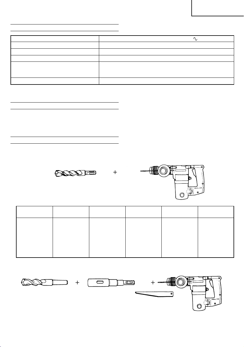
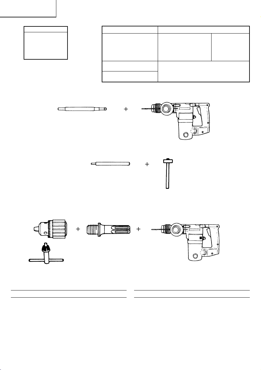
OPTIONAL ACCESSORIES (sold separately)
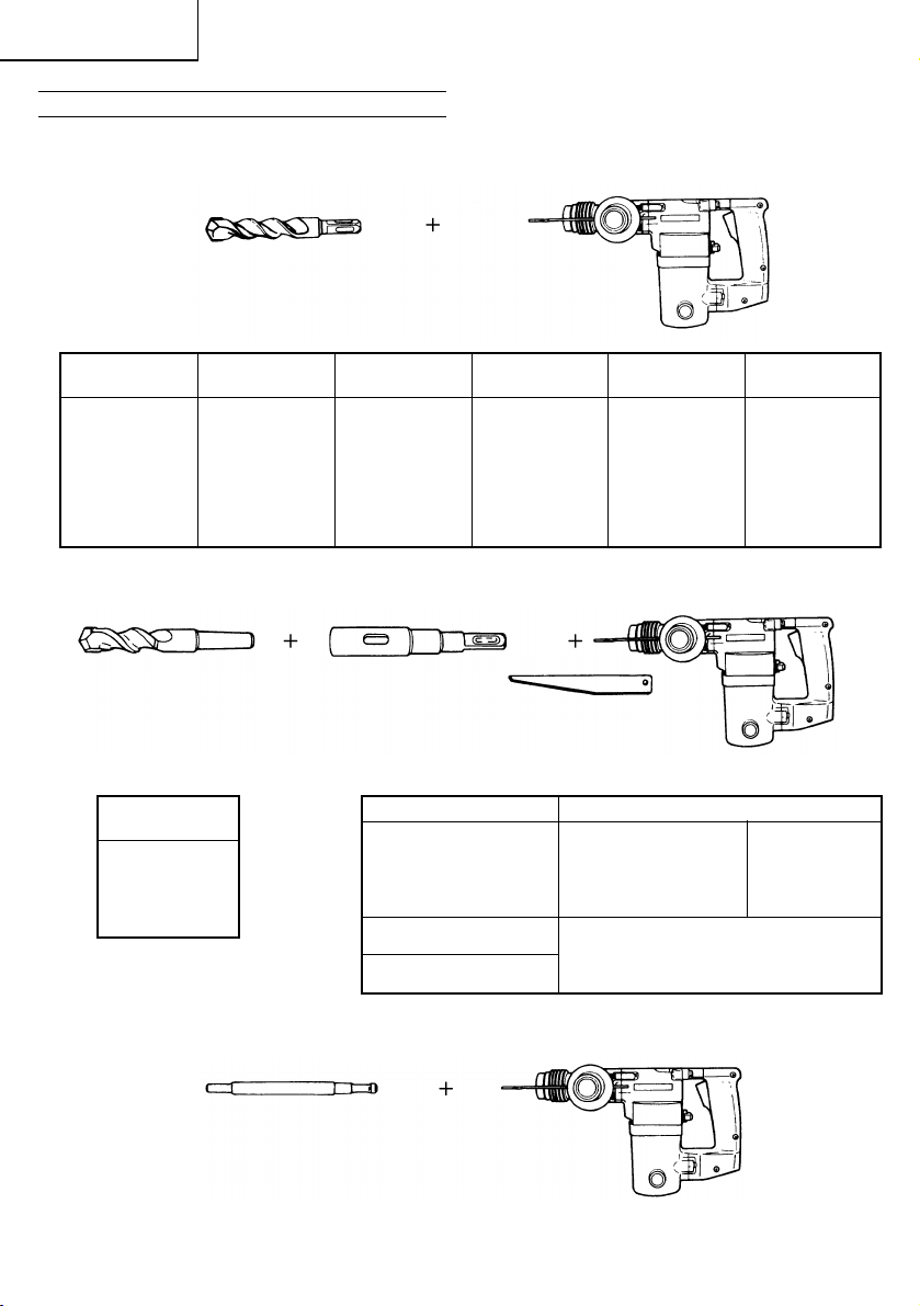
1. Drilling anchor holes (rotation + striking)
䡬 Drill (square shank) (Cannot be attached to the model exclusively intended for the SDS bit.)
English
Drill bit (square shank)
Outer Total Outer Total Outer Total
diameter length diameter length diameter length
5.0 mm 110 mm 8.5 mm 200 mm 16.0 mm 350 mm
5.0 mm 150 mm 9.0 mm 150 mm 17.0 mm 200 mm
5.5 mm 110 mm 12.0 mm 150 mm 19.0 mm 150 mm
6.5 mm 110 mm 12.0 mm 200 mm 19.0 mm 350 mm
6.5 mm 150 mm 12.7 mm 150 mm 20.0 mm 350 mm
7.0 mm 150 mm 14.0 mm 150 mm
8.0 mm 110 mm 15.0 mm 150 mm
8.0 mm 150 mm 16.0 mm 200 mm
䡬 Drill bit (taper shank) and taper shank adapter (Cannot be attached to the model exclusively intended for
the SDS bit.)
Drill bit (taper shank) Taper shank adapter
Cotter
5
Page 7
English
Outer diameter
11.0 mm
12.3 mm
14.3 mm
14.5 mm
17.5 mm
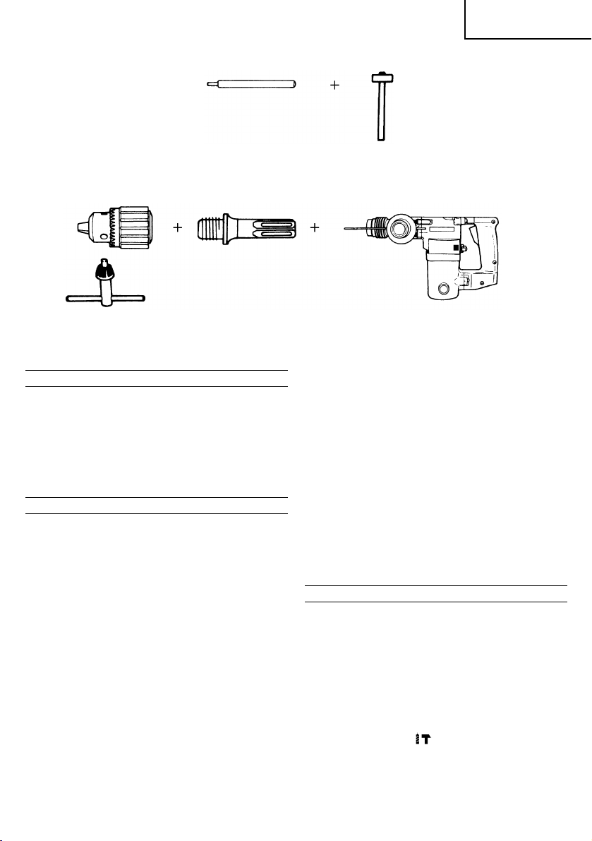
2. Anchor setting (rotation + striking)
䡬 Anchor setting adapter (for electric hammer drill)
Anchor setting adapter
(for electric hammer drill)
Anchor size: W1/4”, W5/16”, W3/8”
䡬 Anchor setting adapter (for manual hammer)
Anchor setting adapter
(for manual hammer)
Anchor size: W1/4”, W5/16”, W3/8”, W1/2”
3. Drilling holes in steel or wood (rotation only)
䡬 Drill chuck and chuck adapter (Also available for the model exclusively intended for the SDS bit.)
Taper mode Applicable drill bit
Morse taper
(No. 1)
A-taper
B-taper
Drill bit
(taper shank)
Taper shank adapter formed A-taper or
B-taper is provided as an optional accessory, but the drill bit for it is not provided.
11.0 mm
12.3 mm
14.3 mm
14.5 mm
17.5 mm
13 mm drill chuck
(including chuck wrench)
Optional accessories are subject to change without notice.
APPLICATIONS
Rotation and striking function:
䡬 Drilling anchor holes
䡬 Drilling holes in concrete
䡬 Drilling holes in tile
Rotation only function:
䡬 Drilling in steel or wood (with optional accessories)
6
PRIOR TO OPERATION
1. Power source
Ensure that the power source to be utilized conforms
to the power requirements specified on the product
nameplate.
2. Power switch
Ensure that the power switch is in the OFF position.
If the plug is connected to a receptacle while the
power switch is in the ON position, the power tool
will start operating immediately, which could cause
a serious accident.
Page 8

English
3. Extension cord
When the work area is removed from the power
source, use an extension cord of sufficient thickness
and rated capacity. The extension cord should be
kept as short as practicable.
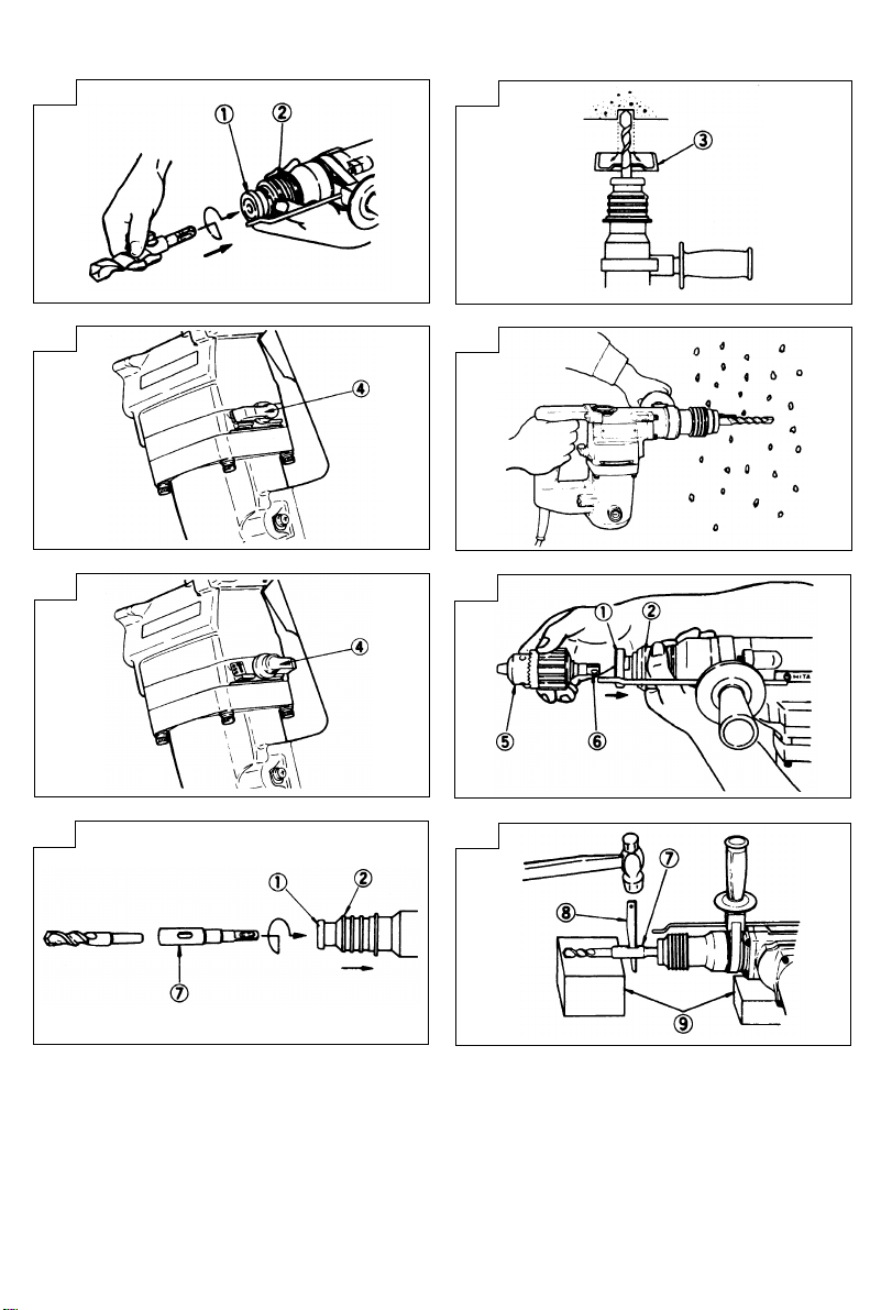
4. Mounting the drill bit (Fig.1)
Please operate the model exclusively intended for
the SDS bit as described below.
Fully shift the slide grip of the chuck section in the
direction of arrow and insert the drill bit while rotating
it slowly. Match the drill bit to the square hole in
the slide grip and firmly insert it. The drill bit is firmly
locked in place when the slide grip is returned to
its original position. Remove the drill bit in the reverse
order of installation. Do not fail to use HITACHI
GENUINE DRILL BIT. Although the chuck section is
of dust-proof construction, the movement of slide
grip may become dull due to concrete dust after the
machine has been used for long periods. Lubricate
the sliding part of the slide grip.
5. Mounting the dust cup (Fig.2)
When it is necessary to drill a hole with the drill
bit facing upward, such as drilling holes in a ceiling,
use of a dust cup will minimize falling particles to
attain easy drilling work. Mount the dust cup to the
drill bit as shown in Fig.2.
When using a large drill bit, enlarge the hole in the
center when mounting it on the drill bit.
HOW TO USE
Please operate the model exclusively intended for the
SDS bit as described below.
1. Switch operation
The rotational speed of the drill bit can be controlled
by varying the amount that the trigger switch is
pulled. Speed is low when the trigger switch is
pulled slightly and increaes when the switch is
pulled more.
2. Rotation + striking
This hammer drill can be set to rotation and striking
mode by rotating the selector lever fully counter-
clockwise to
(1) Mount the drill bit
(2) Pull the trigger switch after placing the drill bit tip
in the drilling position. (Fig.4)
(3) Pushing the hammer drill forcibly is not necessary.
It is sufficient to push slightly so that drill dust
comes out gradually.
CAUTION
When the drill bit touches construction iron bar, the
bit will stop immediately and the hammer drill react
to revolving. Therefore, grip the side handle and
handle tightly.
3. Rotation only
The hammer drill can be set to rotation only mode
by rotating the selector lever fully clockwise to
mark. (Fig.5)
(1) Attach the drill chuck and chuck adapter (optional
accessories). The hammer drill can be used for
drilling of steel and wood materials with these
accessories.
In order to attach the accessories, fully withdraw
the slide grip of chuck section in the direction of
the arrow in Fig.6.
mark. (Fig.3)
Slightly insert the chuck adapter into the square
hole of the slide grip by rotating; fully insert the
chuck adapter after it is matched with the square
hole. Return the slide grip to its original position
so that the chuck adapter is locked tight.
For removal of the accessories, reverse the above
procedures.
(2) Application of excessive force will not expedite the
work, but will only deteriorate the tip edge of the
drill bit resulting in reduced service life of the
hammer drill.
(3) When the hole is nearly completed, the drill bit
sometimes breaks. When the hole is nearly
completed, release the pushing force.
CAUTION
After drilling is finished, always disconnect the plug
from the receptacle.
4. How to use the drill bit (taper shank) and the taper
shank adapter
(1) Mount the taper shank adapter to the hammer drill.
(Fig.7)
(2) Mount the dill bit (taper shank) to the taper shank
adapter. (Fig.7)
(3) Turn the switch ON, and drill a hole of prescribed
depth.
(4) To remove the drill bit (taper shank), insert the
cotter into the slot of the taper shank adapter that
is supported by the rest and strike the head of the
cotter with a hammer (Fig.8).
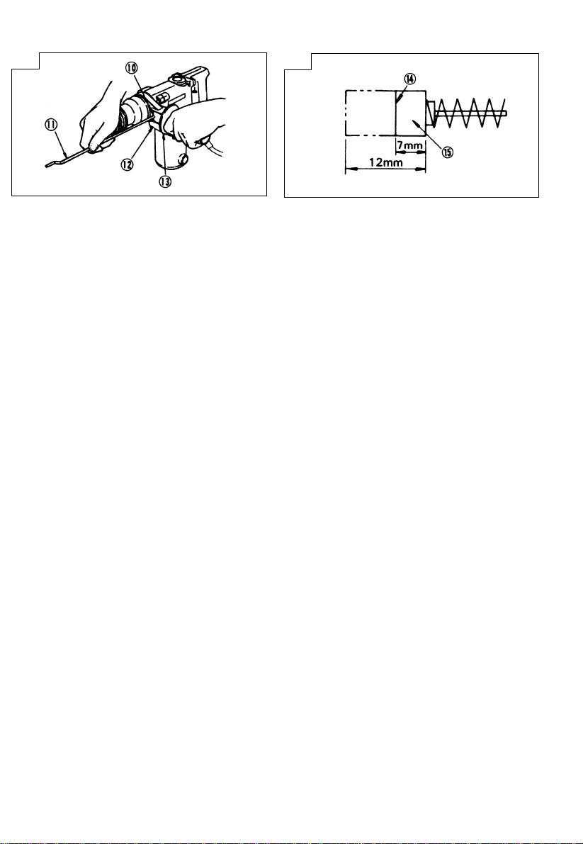
5. How to use the stopper
Fixing the stopper (Fig.9)
(1) Loosen the side handle and insert the linear part
of the stopper into the fitting hole of the handle
holder from the chuck section side.
(2) Move the stopper to its prescribed position while
the side handle is left loosened, then rotate the side
handle clockwise to fix the stopper.
LUBRICATION
Low viscosity grease should be applied to this hammer
drill so that it can be used for a long period without
replacing the grease. Please contact the nearst service
agent for grease replacement if grease leaks from
loosened screws.
Continued use of the hammer drill despite a grease
shortage will cause reduction of the service life.
CAUTION
The specified grease should be used in this machine.
Therefore, the normal performance of the machine may
be negatively affected by use of another grease. Please
be sure to ask our service agent for replacement of the
grease.
MAINTENANCE AND INSPECTION
CAUTION
Be sure to run power OFF and disconnect the plug
during maintenance and inspection.
1. Inspecting the drill bits
Since use of a dull drill bit will cause motor
malfunctioning and reduced efficiency, replace the
drill bit with a new one or resharpen without delay
when abrasion is noted.
7
Page 9

English
Deutsch
2. Inspecting the mounting screws:
Regularly inspect all mounting screws and ensure
that they are properly tightened. Should any of the
screws be loose, retighten them immediately. Failure
to do so could result in serious hazard.
3. Maintenance of the motor
The motor unit winding is the very ”heart” of the
power tool. Exercise due care to ensure the winding
does not become damaged and/or wet with oil or
water.
4. Inspecting the carbon brushes (Fig.10)
The motor employs carbon brushes which are
consumable parts. When they become worn to or
near the ”wear limit”, it could result in motor trouble.
When an auto-stop carbon brush is equipped, the
motor will stop automatically.
At that time, replace both carbon brushes with new
ones which have the same carbon brush numbers
shown in the figure. In addition, always keep carbon
brushes clean and ensure that they slide freely
within the brush holders.
䡬 Replacing a carbon brush:
Disassemble the brush cap with a minus-head screwdriver. The carbon brush can then be easily removed.
NOTE
Due to HITACHI’s continuing program of research and
development, the specigications herein are subject to
change without prior notice.
IMPORTANT
Correct connection of the plug
The wires of the main lead are coloured in accordance
with the following code:
Blue: -Neutral
Brown: -Live
As the colours of the wires in the main lead of this
tool may not correspond with the coloured markings
identifying the terminals in your plug, proceed as follows:
The wire coloured blue must be connected to the
terminal marked with the letter N or coloured black.
The wire coloured brown must be connected to the
terminal marked with the letter L or coloured red.
Neither core must be connected to the earth terminal.
NOTE
This requirement is provided according to BRITISH
STANDARD 2769: 1984.
Therefore, the letter code and colour code may not be
applicable to other markets except The United Kingdom.
Information concerning airborne noise and vibration
The measured values were determined according to
EN50144.
The typical A-weighted sound pressure level: 92 dB (A)
The typical A-weighted sound power level: 105 dB (A)
Wear ear protection.
The typical weighted root mean square acceleration
value: 7.5 m/s
2
ALLGEMEINE VORSICHTSMASSNAHMEN
WARNUNG! Bei der Verwendung von Elektrowerkzeugen
müssen immer die grundlegenden Vorsichtsmaßnahmen
befolgt werden, um das Risiko von Feuer, elektrischem
Schlag und persönlicher Verletzung und den
nachfolgenden Punkten zu vermeiden.
Lesen Sie diese Anweisungen völlig, bevor Sie dieses
Erzeugnis verwenden, und bewahren Sie diese
Anweisungen auf.
Für sicheren Betrieb:
1. Der Arbeitsplatz sollte sauber gehalten werden.
Unaufgeräumte Arbeitsplätze und Werkbänke
erhöhen die Unfallgefahr.
2. Die Betriebsbedingungen beachten.
Elektrowerkzeuge sollten nicht dem Regen
ausgesetzt werden.
Ebenfalls sollten Sie nicht an feuchten oder nassen
Plätzen gebraucht werden.
Der Arbeitsplatz sollte gut beleuchtet sein.
Verwenden Sie Elektrowerkzeuge nicht an Orten,
an denen die Gefahr von Feuer oder Explosion
besteht.
3. Schutzmaß nahmen gegen elektrische Schläge
treffen. Darauf achten, daß das Gehäuse nicht in
Kontakt mit geerdeten Flachen kommt, z. (z.B.
Rohre, Radiatoren, Elektroherde, Kühlschränke).
4. Kinder sollten vom Gerät ferngehalten werden.
Vermeiden, daß andere Personen mit dem
Werkzeung oder Verlängerungskabel in Kontakt
kommen.
5. Nicht benutzte Werkzeuge sollten sicher aufbewahrt
werden. Sie sollten an einem trockenen und
verschließbaren Ort aufbewahrt werden, damit
Kinder sie nicht in die Hände bekommen.
6. Werkzeuge sollten nicht mit übermäßiger Gewalt
verwendet werden. Ihre Leistung ist besser und
sicherer, wenn sie mit der vorgeschriebenen
Geschwindigkeit verwendet werden.
7. Nur die korrekten Werkzeuge verwenden. Niemals
ein kleineres Werkzeug oder Zusatzgerat für
Arbeiten verwenden, die Hochleistungsgerate
erfordern. Nur Werkzeuge verwenden, die dem
Verwendungszweck entsprechen, d.h. niemals eine
Kreissäge zum Sägen von Ästen oder
Baumstämmen verwenden.
8. Die richtige Kleidung tragen. Keine lose Kleidung
oder Schmuck tragen, da sich lose Kleidungsstücke
in den bewegenden Teilen verfangen kònnen. Bei
Arbeiten im Freien sollten Gummihandschuhe und
rutschfeste Schuhe getragen werden.
9. Es sollte eine Sicherheitsbrille getragen werden.
Bei Arbeiten mit Staubentwicklung sollte eine
Gesichtsoder Staubmaske getragen werden.
10. Schließen Sie eine Staubabsaugvorrichtung an.
Wenn Vorrichtungen für den Anschluß von
Staubabsaug- und -sammelvorrichtungen
vorhanden sind, so stellen Sie sicher, daß diese
angeschlossen sind und richtig verwendet werden.
11. Niemals das Kabel mißbrauchen. Ein Werkzeug
niemals am Kabel tragen oder bei Abtrennung von
der Steckdose das Kabel harausreißen. Das Kabel
sollte gegen Hitze, Öl und scharfe Kanten geschützt
werden.
12. Den Arbeitsplatz gut absichern. Zwingen oder einen
Schraubstock zur Befestigung des Werkstücks
verwenden. Das ist sicherer als die Benutzung der
Hände und macht beide Hände zur Bedienung des
Werkzeugs frei.
13. Sich niemals weit überbeugen. Immer einen festen
Stand und ein sicheres Gleichgewicht bewahren.
8
Page 10

Deutsch
14. Die Werkzeuge sollten sorgfältig behandelt werden.
Für einen einwandfreien und sicheren Betrieb
sollten sie stets scharf sein und saubergehalten
werden. Die Anleitungen für schmierung und
Austausch des Zuehörs unbedingt einhalten. Die
Kabel der Geräte regelmäßig überprüfen und bei
Beschädigung durch eine autorisierte
Kundendienststelle reparieren lassen.
Ebenfalls die Verlägerungskabel regelmäßig
überprüfen und bei Beschadigung auswechseln.
Die Handgriffe sollten stets trocken und sauber
sein, sowie keine Ol- oder Schmierfett stellen
aufweisen.
15. Werkzeuge vom Netz trennen, wenn sie nicht
benutzt werden, vor Wartungsarbeiten und beim
Austausch von Zubehörteilen wie z.B. Blätter,
Bohrer und Messer.
16. Alle Stellkeile und Schraubenschlüssel entfernen.
Vor Einschaltung des Gerätes darauf achten, daß
alle Stellkeile und Schraubenschlüssel entfernt
worden sind.
17. Ein unbeabsichtigtes Einschalten sollte vermieden
werden. Niemals ein angeschlossenes Werkzeug
mit dem Finger am Schalter tragen. Vor Anschluß
überprüfen, ob das Gerät ausgeschaltet ist.
18. Im Freien ein Verlängerungskabel verwenden. Nur
ein Verlängerungskabel verwenden, das für die
Verwendung im Freien markiert ist.
19. Den Arbeitsvorgang immer unter Kontrolle haben.
Das Gerät niemals in einem abgespannten Zustand
verwenden.
20. Beschädigte Teile überprüfen. Vor Benutzung des
Werkzeugs sollten beschädigte Teile oder
Schutzvorrichtungen sorgfältig überprüft werden,
um festzustellen, ob sie einwandfrei funktionieren
und die vorgesehene Funktion erfüllen,
Ausrichtung, Verbindungen sowie Anbringung sich
bewegender Teile überprüfen. Ebenfalls
uberprufen, ob Teile gebrochen sind. Teile oder
Schutzvorrichtungen, die beschädigt sind, sollten,
wenn in dieser Bedienungsanleitung nichts anderes
erwähnt ist, durch eine autorisierte
Kundendienststelle ausge wechselt oder repariert
werden. Dasselbe gilt für defekte Schalter.
Wenn sich das Werkzeug nicht mit dem Schalter
einoder ausschalten läßt, sollte das Werkzeug nicht
verwendet werden.
21. Warnung
Die Verwendung von anderem Zubehör oder
anderen Zusätzen als in dieser Bedienungsanleitung
empfohlen kann das Risiko einer Körperverletzung
einschließen.
22. Lassen Sie Ihr Werkzeug durch qualifiziertes
Personal reparieren. Dieses Elektrowerkzeug
entspricht den zutreffenden Sicherheitsanforderungen. Reparaturen sollten nur von
qualifiziertem Personal unter Verwendung von
Originalersatzteilen durchgeführt werden, da sonst
beträchtliche Gefahr für den Benutzer auftreten
kann.
VORSICHTSMASSNAHMEN BEI DER
BENUTZUNG DES BOHRHAMMERS
1. Ohrenstöpsel zum Schutz der Ohren während des
Betriebs tragen.
2. Die Bohrerspitze nicht während oder unmittelbar
nach dem Betrieb berühren. Die Bohrerspitze wird
während des Betriebs sehr heiß, und es könnte zu
ernsthaften Verbrennungen kommen.
3. Bevor man in einer Wand, dem Boden oder der
Decke etwas ausbricht, meißelt oder bohrt, muß
man sich sorgfältig davon überzeugen, daß keine
elektrischen Kabel oder Kabelrohre darunter liegen.
TECHNISCHE DATEN
Spannung (je nach Gebiet)* (110V, 220V, 230V, 240V)
Leistungsaufnahme* 460W
Leerlaufdrehzahl 0-900/min
Vollastschlagzahl 3500/min
Kapazität: Beton 20 mm
Gewicht (ohne Kabel und Handgriff) 3,1 kg
* Vergessen Sie nicht, die Produktangaben auf dem Typenschild zu überprüfen, da sich diese je nach Verkaufsgebiet
ändern.
Stahl 13 mm
Holz 15 mm
STANDARDZUBEHÖRE
(1) Gehäuse (Plastik) ...................................................... 1
(2) Handgriff .................................................................. 1
(3) Anschlag .................................................................. 1
(4) Staubfänger................................................................ 1
Das Standardzubehör kann ohne vorherige Bekanntmachung jederzeit geändert werden.
9
Page 11
Deutsch
SONDERZUBEHÖRE (separat zu beziehen)
1. Bohren von Ankelöchern (Schlag-und Drehbohrer)
䡬 Bohrer (Vierkantschaft) (Kann nicht an dem Modell angebracht werden, das nur für SDS-Futter ausgelegt ist.)
Bohrer (Vierkantschaft)
Außendurch- Außendurch- Außendurch-
messer messer messer
5,0 mm 110 mm 8,5 mm 200 mm 16,0 mm 350 mm
5,0 mm 150 mm 9,0 mm 150 mm 17,0 mm 200 mm
5,5 mm 110 mm 12,0 mm 150 mm 19,0 mm 150 mm
6,5 mm 110 mm 12,0 mm 200 mm 19,0 mm 350 mm
6,5 mm 150 mm 12,7 mm 150 mm 20,0 mm 350 mm
7,0 mm 150 mm 14,0 mm 150 mm
8,0 mm 110 mm 15,0 mm 150 mm
8,0 mm 150 mm 16,0 mm 200 mm
䡬 Bohrer (Kegeschaft) und Konusschaftadapter (Kan nicht an dem Modell angebracht werden, das nur für SDS-
Futter ausgelegt ist.)
Bohrer (Kegelschaft) Konusschaftadapter
Außendurch-
messer
11,0 mm
12,3 mm
14,3 mm
14,5 mm
17,5 mm
Gesamtlänge Gesamtlänge Gesamtlänge
Keil
Konusschaftadapter Anwendbare Bohrer
11,0 mm
Morsekonus
(Nr. 1)
A-Konus
B-Konus
Bohrer
(Konusschaft)
Der Konusschaftadapter in From von
A-Konus oder B-Konus wird wahlseise
geliefert, aber die passenden Bohrer
werden nicht mitgeliefert.
12,3 mm
14,3 mm
14,5 mm
17,5 mm
2. Ankerbefestigung (Schlag- und Drehbohrer)
䡬 Adapter für Ankerbefestigung (für Bohrhammer)
Adapter für Ankerbefestigung
(für Bohrhammer)
Ankergröße: W1/4", W5/16", W3/8"
10
Page 12
Deutsch
䡬 Adapter für Ankerbefestigung (mit dem Handhammer)
Adapter für Ankerbefestigung
(mit dem Handhammer)
Ankergröße: W1/4", W5/16", W3/8", W1/2"
3. Löcherbohren in Stahl oder Holz (Drehbohrer)
䡬 Bohrfutter und Bohrfutteradapter (Auch für das Modell, das nur für SDS-Futter ausgelegt ist, erhältlich.)
Bohrfutter 13 mm
(mit Bohrfutterschlüssel)
Das Sonderzubehör Kann ohne vorherige Bekanntmachung jederzeit geändert werden.
ANWENDUNG
Schlag- und Drehbohrefunktion:
䡬 Bohren von Ankerlöchern
䡬 Bohren von Löchern in Beton
䡬 Bohren von Löchern in Kachel
Nur Drehbohrerfunktion:
䡬 Bohren von Löchern in Stahl oder Holz (mit
Sonderzubehör)
VOR INBETRIEBNAHME
1. Netzspannung
Prüfen, daß die zu verwendende Netzspannung der
Angabe auf dem Typenschild entspricht.
2. Netzschalter
Prüfen, daß der Netzschalter auf „AUS“ steht. Wenn
der Stecker an das Netz angeschlossen wird, während
der Schalter auf „EIN“ steht, beginnt das Werkzeug
sofort zu laufen, was gefährlich ist.
3. Verlängerungskabel
Wenn der Arbeitsbereich nicht in der Nähe des
Netzanschlusses liegt, ist ein Verlängerungskabel
ausreichenden Querschnitts und ausreichender
Nennleistung zu verwenden. Das Verlängerungskabel
sollte so kurz wie möglich gehalten werden.
4. Anbringung des Bohrers (Abb.1)
Das Modell, das für SDS-Futter ausgelegt ist, wird
wie unten beschrieben gehandhabt.
Die Schiebe-Spannklaue des Bohrfutterteils
vollständig in die Pfeilrichtung schieben und den
Bohrer einsetzen, während sie rotiert wird. Den
Bohrer auf die quadratische Öffnung der SchiebeSpannklaue ausrichten und den Bohrer einschieben.
Wenn die Schiebe-Spannklaue zu ihrer
Ausgangsstellung zurückgebracht wird, ist der Bohrer
fest eingespannt.
Für die Entfernung des Bohrers das Einspannverfahren in umgekehrter Reihenfolge ausführen. Nur
ORIGINAL-HITACHI-BOHRER verwenden.
Obwohl der Bohrfutterteil gegen Staub geschützt
ist, könnte sich die Schiebe-Spannklaue nach längerer
Benutzung des Gerätes aufgrund von Betonstaub
nur schwer bewegen lassen. Deshalb den Gleitteil
der Schiebe-Spannklaue schmieren.
5. Anbringung des Staubfängers (Abb.2)
Wenn Bohrarbeiten ausgeführt werden müssen, bei
denen der Bohrer nach oben zeigt, z.B. beim Bohren
von Decken, sollte für ein leichteres Bohren und
zum Auffangen der Staubpartikel ein Staubfänger
angebracht werden. Den Staubfänger wie in Abb.2
gezeigt am Bohrer anbringen. Wenn ein größerer
Bohrer verwendet wird, die Öffnung in der Mitte bei
Anbringung am Bohrer vergrößern.
BENUTZUNG
Das Modell, das für SDS-Futter ausgelegt ist, wird wie
unten beschrieben gehadhabt.
1. Betätigung des Schalters
Die Drehzahl des Bohrers kann durch Veränderung
des Druckes auf den Drückerschalter gesteuert
werden. Die Geschwindigkeit ist gering, wenn der
Drückerschalter nur leicht gezogen ist, und erhöht
sich, wenn der Schalter weiter durchgezogen wird.
2. Schlag-und Drehbohrer
Dieser Bohrhammer kann durch vollsäandiges
Drehen des Wahlhebels im Gegenuhrzeigersinn, d.h.
Einstellung auf die
Drehbohrer verwendet werden (Abb.3)
(1) Die Bohrerspitze anbringen
(2) Nach Aufsetzen der Bohrkronenspitze auf die
Bohrstelle den Auslöse-Schalter drücken. (Abb.4)
(3) Der Bohrhammer braucht nicht mit Gewalt gegen
Markierung, als Schlag-und
11
Page 13

Deutsch
die Bohrstelle gedrückt zu werden. Nur geringfügig
andrücken, so daß der Borhrstaub gleichmäßig aus
dem Bohrloch kommt.
ACHTUNG
Wenn der Bohrer auf Eisendraht stößt, stoppt der
Bohrer augenblicklich, wodurch das Gerät sich zu
drehen beginnt. Deshalb Handgriff sowie Seitengriff
gut umfassen.
3. Nur Drehbohrer
Durch vollständiges Drehen des Wahlhebels im
Uhrzeigerssin, d.h. Einstellung auf die
kann der Bohrhammer als Drehbohrer verwendet
werden (Abb.5).
(1) Das Bohrfutter und den Futteradapter
(Sonderzubehör) anbringen. Dann kann Bohrhammer
zum Bohren von Stahl-und Holzmaterialien
verwendet werden.
Zur Anbringun der Zusatzgeräte die SchiebeSpannklaue des Bohrfetterteils vollständig in
Pfeilrichtung zurückschieben. (Abb.6)
Den Futteradapter zuerst kurz durch Drehen der
Schiebe-Spannklaue in dessen quadratische Öffnung
einsetzen. Wenn der Futteradapter mit der
quadratische Öffnung ausgerichtet worden ist, den
Adapter vollständig einschieben. Die SchiebeSpannklaue zur Zusgangsposition zurückschieben,
um den Futteradapter einzuspannen.
Für Entfernung der Zusatzgeräte das oben genannte
Verfahren in umgekehrter Reihenfolge ausführen.
(2) Wenn beim Bohren übermäßige Gewalt angewandt
wird, wird der Bohrzapfenrand der Bohrkrone
beschädigt, wodurch die Lebensdauer der
Bohrhammers verkürzt wird.
(3) Es kann vorkommen, daß der Bohrer kurz vor dem
Durchstoßen des Bohrlochs abbricht. Deshalb kurz
vorher die Schlagkraft verringern.
ACHTUNG
Nach Beendigung der Bohrung stets den Stecker
aus der Steckdose ziehen.
4. Benutzung des Bohrers (Kegelschafts) und des
Kegelschaftadapters
(1) Den Kegelschaftadapter am bohrhammer anbringen.
(Abb.7)
(2) Den Bohrer (Kegelschaft) am Kegelschafadapter
anbringen. (Abb.7)
(3) Den Schalten und ein Loch mit der vorgegebenen
Tiefe bohren.
(4) Zur Entfernung des Bohrers (kegelschafts) einen Dorn
in den Schlitz des Kagelschaftadapters einführen und
mit einem Hammer gestützt durch eine Auflage auf
den Kopf des Dorns schlagen. (Abb.8)
5. Benutzung des Anschalgs
Anbringung des Anschalgs (Abb.9):
(1) Den Seitengriff lösen und den geraden Teil des
Anschlags in das Paßloch des Griffhalters von der
Bohrfutterseite her einführen.
(2) Den Anschlag in die vorgeschriebene Position
bringen, während der Seitengriff gelöst ist, und
dann den Seitengriff zur Anbringung des Anschlags
im Uhrzeigersinn drehen.
Markierung,
SCHMIERUNG
Für diesen Bohrhammer sollte ein Schmiermittel mit
niedriger Viskosität verwendet werden, damit er über
einen längeren Zeitraum ohne Schmierfettwechsel
verwendet werden kann. Sollte Schmierfett aufgrund
gelöster Schrauben austreten, bitte für die Auswechslung
des Schmierfetts die nächstgelegene Kundendienststelle
aufsuchen.
12
Wird der Bohrhammer in solch einem Fall
weiterverwendent, könnte sich das Gerät festfressen,
wodurch die Lebensdauer verkürzt wird.
ACHTUNG
Es sollten nur die vorgeschriebenen Schmiermittel
verwendet werden. Wenn andere Schmiermittel
verwendet werden, könnte die Leistung des Gerätes
beeinträchtigt werden. Wenden Sie sich bitte für die
Answechslung der Schmiermittel an unsere
Kundendienstselle.
WARTUNG UND INSPEKTION
ACHTUNG
Vor Wartung und Inspektionn das Gerät ausschalten
und aus der Stekdose ziehen.
1. Inspektion des Bohrers
Fortgesetzte Verwendung eines stumpfen oder
beschädigten Bohrers führt zu verminderter
Bohrleistung und kann den Motor der Bohrmaschine
erheblich überlasten. Den Bohrer regelmäßig
überprüfen und erforderlichenfalls durch einen neuen
Bohrer erstzen.
2. Inspektion der Befestigungsschrauben:
Alle Befestigungsschrauben werden regelmäßig
inspiziert und geprüft, ob sie gut angezogen sind.
Wenn sich eine der Schrauben lockert, muß sie
sofort wieder angezogen werden. Geschieht das
nicht, kann das zu erheblichen Gefahren führen.
3. Wartung des Motors:
Die Motorwicklung ist das „HERZ“ des
Elektrowerkzeugs. Daher ist besonders sorgfältig
darauf zu achten, daß die Wicklung nicht beschädigt
wird und/oder mit Öl oder Wasser in Berührung
kommt.
4. Inspektion der Kohlebürsten (Abb.10)
Im Motor sind Kohlebürsten verwendet, die
Verbrauchsteile sind. Wenn sie abgenützt sind, kann
es zu Motorschäden führen. Wenn der Motor mit
einer Auto-Stop Kohlebürste ausgestattet ist, wird
er automatisch anhalten. Beide Kohlebürsten sollen
dann durch neue ersetzt werden, die dieselbe
Bürstennummer tragen, wie auf der Abbildung.
Darüber hinaus müssen die Kohlebürsten immer
sauber gehalten werden und müssen sich in der
Bürstenhalterung frei bewegen können.
䡬 Austausch einer Kohlebürste:
Der Bürstendeckel wird mit einem Steckschlüssel
abmontiert. Dann kann die Kohlebürste leicht entfernt
werden.
ANMERKUNG
Aufgrund des ständigen Forschungs-und Entwicklungsprogramms von HITACHI sind Änderungen den hierin
gemachten technischen Angaben nicht ausgeschlossen.
Information über Betriebslärm und Vibration
Die Meßwerte wurden entsprechend EN50144 bestimmt.
Der typische A-gewichtete Schalldruckt ist 92 dB (A).
Der typische A-gewichtete Schalleistungspegel ist
105 dB (A).
Bei der Arbeit immer einen Ohrenschutz tragen.
Der typische gewogene quadratische Mittelwert für die
Beschleunigung ist 7,5 m/s2.
Page 14

Français
PRECAUTIONS GENERALES DE TRAVAIL
ATTENTION! Lors de l’utilisation d’un outillage
électrique, les précautions de base doivent être
respectées de manière à réduire les risques d’incendie,
de secousse électrique et de blessure corporelle, y
compris les précautions suivantes.
Lire ces instructions avant d’utiliser le produit et
conserver ces instructions pour référence.
Pour assurer un fonctionnement sûr:
1. Maintenir l’aire de travail propre. Des ateliers ou
des établis en désordre risquent de provoquer des
accidents.
2. Tenir compte de l’environnement de l’aire de tra
vail. Ne pas exposer les outils électriques à la
pluie.
Ne pas les utiliser dans des endroits humides.
Travailler dans un endroit bien éclairé.
Ne pas utiliser d’outillage électrique s’il existe un
risque d’incendie ou d’explosion.
3. Protection contre une décharge électrique. Eviter
tout contact corporel avec des surfaces de mise
à la terre telles que les tuyaux, radiateurs,
cuisinières et réfrigérateurs.
4. Tenir les enfants éloignés. Ne pas laisser les
visiteurs toucher l’outil ou son cordon
d’alimentation. Il est préférable de tenir les visiteurs
à l’écart de l’aire de travail.
5. Ranger les outils non utilisés. Quand on ne les
utilise pas, il est recommandé de ranger les outils
dans un endroit sec, verrouillé ou hors de portée
des enfants.
6. Ne pas forcer l’outil. Il fonctionnera mieux et plus
sûrement à la vitesse pour laquelle il a été con
cu.
7. Utiliser l’outil approprié. Ne pas essayer de faire
avec un petit outil le travail prevu pour un outil
plus important. Toujours utiliser l’outil adéquat;
par exemple, ne pas se servir d’une scie circulaire
pour couper des branches d’arbres ou des billots
de bois.
8. Porter des vêtements appropriés. Ne pas mettre
de vêtements flottants ou de bijoux qui risquent
d’être pris dans les pièces mobiles. Si l’on travaille
à l’extérieur, il est recommandé de porter des
gants de caoutchouc et des chaussures à semelles
antidérapantes. Veiller à s’attacher les cheveux ou
à mettre un bonnet si on a les cheveux longs.
9. Porter des lunettes protectrices. Mettre un masque
si l’opération de coupe crée de la poussière.
10. Relier l’équipement d’extraction de poussière.
Si des dispositifs sont prévus pour le raccordement
d’installations d’extraction et de collection de
poussière, s’assurer qu’ils sont correctement
raccordés et utilisés.
11. Prendre soin du fil. Ne jamais transporter l’outil
en le tenant par le fil et ne pas le débrancher en
tirant sur le fil d’un coup sec. Tenir le fil à l’abri
de la chaleur, l’éloigner de l’huile ou de bords
tranchants.
12. Fixer fermement la piêce à travailler. Utiliser des
agrafes ou un étau pour la maintenir, C’est plus
sûr que d’utiliser ses mains et cela les libêre pour
faire fonctionner l’outil.
13. Ne pas présumer de ses forces. Essayer de garder
son équilibre en toute circonstance.
14. Entretenir les outils avec soin. Les conserver bien
aiguisés et les nettoyer afin d’en obtenir les
meilleures performances et de pouvoir les utiliser
sans danger. Suivre les instructions pour le
graissage et le changement des accessoires. Vérifier
régulièrement les fils et cordons et s’ils sont
endommagés, les faire réparer par une personne
compétente. Vérifier régulièrement les rallonges et
les remplacer si elles sont endommagées. Veiller
à ce que les poignées soient toujours sèches et
propres, sans huile ni graisse.
15. Debrancher les outils lorsqu’on ne les utilise pas,
avant toute opération d’entretien et lors du
changement d’accessoire; comme par exemple
quand on change les lames, les forets, le fraises,
etc.
16. Retirer les clés de réglage. Prendre l’habitude de
toujours vérifier que les clés de réglage sont bien
retirées de l’appareil avant de le mettre en marche.
17. Eviter toute mise en marche accidentelle. Ne pas
transporter l’outil branché avec un doigt sur
l’interrupteur. S’assurer que l’interrupteur est sur
la position d’arrêt quand on branche l’outil.
18. Utilisation de rallonges à l’extérieur. Quand on
utilise l’outil à l’extérieur, ne se servir que des
rallonges prévues pour l’extérieur et portant une
marque distinctive.
19. Soyez vigilant. Regardez bien ce que vous faites.
Faites appel à votre bon sens. N’utilisez pas l’outil
quand vous êtes fatigué.
20. Vérifier les pièces endommagées. Avant d’utiliser
davantage l’outil, vérifier attentivement toute pièce
endommagée afin de déterminer si l’outil peut
fonctionner correctement et effectuer le travail
pour lequel il est prévu. Vérifier l’alignement et
la flexion des piêces mobiles, la cassure des pièces,
le montage et toute autre condition risquant
d’affecter le bon fonctionnement de l’outil. Un
protecteur ou toute autre pièce endommagée devra
être correctement réparé ou remplacé par un
service d’entretien autorisé, sauf autre indication
dans ce mode d’emploi. Faire remplacer les
interrupteurs défectueux par un service d’entretien
autorisé. Ne pas utiliser l’outil si l’interrupteur ne
permet pas de le mettre en marche ou de l’arrêter.
21. Précaution
L’utilisation d’un accessoire ou dispositif annexe
autre que ceux conseillés dans ce mode d’emploi
peut entraîner un risque de blessure corporelle.
22. Confier la réparation d’un outil à un technicien
qualifié. Cet outil électrique a été conçu
conformément aux règles de sécurité en usage.
Les réparations doivent être effectuées par du
personnel qualifié utilisant des pièces d’origine.
Dans le cas contraire, l’utilisateur s’expose à des
risques graves.
PRECAUTIONS POUR L’UTILISATION DU
MARTEAU PERFORATEUR
1. Utiliser des bouchons d’oreilles pour protéger vos
oreilles pendant le fonctionnement.
13
Page 15

Français
2. Ne pas toucher le foret pendant ou immédiatement
après le fonctionnement. Il devient trés chaud et
peut causer brûlures.
3. Avant de briser, découper ou percer un mur, le
plancher ou le plafond, s’assurer qu’aucun câble
électrique ou conduit n’y soit noyé.
SPECIFICATIONS
Tension (par zone)* (110V, 220V, 230V, 240V)
Puissance* 460W
Vitesse sans charge 0-900/min
Vitesse de percussion à pleine charge 3500/min
Capacité:béton 20 mm
Poids (sans fil et poignée latérale) 3,1 kg
* Assurez-vous de vérifier la plaque signalétique se trouvant sur le produit, car elle peut changer suivant les régions.
acier 13 mm
bois 15 mm
ACCESSOIRES STANDARD
(1) Boîtier (Plastique) ...................................................... 1
(2) Poignée latérale ......................................................... 1
(3) Quenouille .................................................................. 1
(4) Godet à poussière ...................................................... 1
Les accessoires standard son sujets à changement sans
préavis.
ACCESSOIRES EN OPTION (vendus séparément)
1. Perçage de trous d’ancrage (rotation + frappe)
䡬 Foret de perçage (queue carrée) (Ne peut être fixé au modèle exclusivement conçu pour la mèche SDS.)
Froet de perçage (queue carrée)
Diamètre Longueur Diamètre Longueur Diamètre Longueur
externe totale externe totale externe totale
5,0 mm 110mm 8,5 mm 200 mm 16,0 mm 350 mm
5,0 mm 150mm 9,0 mm 150 mm 17,0 mm 200 mm
5,5 mm 110mm 12,0 mm 150 mm 19,0 mm 150 mm
6,5 mm 110mm 12,0 mm 200 mm 19,0 mm 350 mm
6,5 mm 150mm 12,7 mm 150 mm 20,0 mm 350 mm
7,0 mm 150mm 14,0 mm 150 mm
8,0 mm 110mm 15,0 mm 150 mm
8,0 mm 150mm 16,0 mm 200 mm
䡬 Foret de perçage (queue conique) et raccord de queue conique (Ne peut être fixé au modèle exclusivement
conçu pour la mèche SDS.)
Foret de perçage
14
Raccord de queue conique
Clavette
Page 16

Français
Diamètre externe
11,0 mm
12,3 mm
14,3 mm
14,5 mm
17,5 mm
2. Mise en place de la fixation (rotation + frappe)
䡬 Raccord de mise en place de la fixation (pour perceuse électrique)
Raccord de mise en place de la fixation
(pour perceuse électrique)
Dimension de I’ancrage: W1/4", W5/16", W3/8"
䡬 Raccord de mise en place de la fixation (pour marteau)
Raccord de mise en place de la fixation
(pour marteau)
Dimension de I’ancrage: W1/4", W5/16", W3/8", W1/2"
3. Perçage de trous dans I’acier ou le bois (rotation seulement)
䡬 Mandrin porte-foret et raccord de mandrin (Egalement disponible pour le modèle exclusivement conçu pour
la mèche SDS.)
Type de cône Foret de perçage utilisé
Cône Morse
(Nr. 1)
Cône en A
Cône en B
Foret de perçage
(queue conique)
Le raccord de queue conique en forme
cône-A ou cône-B est fourni en tant
qu’accessoire en option, mais la mèche
correspondante n’est pars fournie.
11,0 mm
12,3 mm
14,3 mm
14,5 mm
17,5 mm
Mandrin porte-foret 13 mm
(compris la clé de mandrin)
Les accessoires standard sont sujets à changement sans préavis.
APPLICATIONS
Par action combinée de rotation et de frappe:
䡬 Perçage de trous d’ancrage
䡬 Perçage de trous dans el béton
䡬 Perçage de trous dans une tuile
Par action de ratation uniquement:
䡬 Perçage de I’acier ou du bois (avec accessoires en
option)
2. Interrupteur de puissance
3. Fil de rallonge
AVANT LA MISE EN MARCHE
1. Source de puissance
S’assurer que la source de puissance à utiliser
correspond à la puissance indiquée sur la plaque
signalétique du produit.
4. Montage du foret de perçage (Fig.1)
S’assurer que l’interrupteur de puissance est en
position ARRET. Si la fiche est branchée alors que
s’assurer que I’interrupteur de puissance est en
position ARRET. Si la fiche est branchée alors que
I’interrupteur est sur MARCHE, l’outil démarre
immédiatement et peut provoquer un grave accident.
Lorsque la zone de travail est éloignée de la source
de puissance, utiliser un fil de rallonge d’une
épaisseur suffisante et d’une capacité nominale
suffisante. Le fil de rallonge doit être aussi court
que possible.
Prière d’utiliser le modéle exclusivement conçu pour
la mèche SDS, comme décrit ci-dessous.
15
Page 17

Français
Faire basculer complètement I’attache coulissante
de la section du mandrin dans le sens indiqué par
la fléche; introduire le foret de perçage en le faisant
tourner lentement. Mettre en place le foret de perçage
dans le trou carré se trouvant sur I’attache coulissante
et bien I’enfoncer. Le foret de perçage est fermement
bloqué en position quand I’attache coulissante
reprend sa position de départ. Pour démonter le
foret de perçage, répéter I’opération dans le sens
inverse. N’utiliser qu’un foret de perçage de la
marque HITACHI, exclusivement.
Bien que la section du mandrin soit protégée de
la poussière, il se peut que le mouvement de l’attache
coulissante soit moins souple en raison d’une
accumulation de poussière de béton après une
utilisation prolongée de l’outil. Graisser la partie
coulissante de I’attache coulissante.
5. Montage du godet à poussière (Fig.2)
Quand il faut percer un trou avec le foret de perçage
orienté vers le haut, comme par exemple lorsqu’on
perce un trou dans un plafond, utiliser le godet á
poussière qui réduira au minmun la chute des
particules et facilitera le travail de perçage. Monter
le godet à poussière sur le foret de perçage comme
indiqué sur la Fig.2. Lors de l’utilisation d’un foret
de perçage de grand format, agrandir le trou au
centre et monter le godet sur le foret.
UTILISATION
Prière d’utiliser le modèle exclusivement conçu pour la
mèche SDS, comme décrit ci-dessous.
1. Fonctionnement de l’interrupteur
La vitesse de rotation du foret de perçage peut être
réglée suivant la force avec laquelle on appuie sur
l’interrupteur à détente. La vitesse est faible si on
exerce une légère pression et augmente si la pression
est plus forte.
2. Rotation + Frappe
Cette perceuse à precussion peut être mise sur le
mode de rotation et frappe en faissant complètement
tourner les sélecteur dans le sens contraire des
aiguilles d’une montre vers le repère
(1) Monter le foret de perçage.
(2) Appuyer sur l’interrupteur de déclenchement après
avoir appliqué la pointe du foret sur la position de
perçage désirée. (Fig.4)
(3) Il n’est pas nécessaire d’appliquer une forte pression
sur la perceuse. Il suffit d’appliquer une légère
pression de manière à ce que les éclats soient
déchargés progressivement.
ATTENTION
Quand le foret de perçage touche une barre d’acier,
la mèche s’arrête immédiatement et la perceuse
réagira en tournant. Par conséquent, tenir fermement
la poignée principale et la poignée latérale.
3. Rotation uniquement
La perceuse à precussion peut être mise sur le
mode de rotation uniquement en faisant tourner le
sélecteur complètement dans le sens d’une montre
vers le repère
(1) Monter le mandrin porte-foret et le raccord de
mandrin (accessoires en option).
Dans ce cas, on peut percer de l’acier ou du bois.
Sante de la section du mandrin en suivant le sens
indiqué par la flèche à la Fig.6. Introduire légèrement
16
. (Fig.5)
. (Fig.3)
le raccord du mandrin dans le trou carré de I’attache
coulissante en faisant tourner et l’introduire
complètement quand il coïncie exactement avec le
trou carré. Remettre I’attache coulissante dans sa
position d’origine de façon à ce que le raccord de
mandrin soit bien verrouillé en position. Pour enlever
les accessoires, procéder à I’inverse de ce qui est
décrit ci-dessus.
(2) Si l’on applique une force excessive, cela donnera
un travail bâclé et abîmera la pointe du foret de
perçage, réduisant ainsi la durée de service de la
perceuse à percussion.
(3) Quand le trou est presque complètement percé, le
foret de perçage est parfois brisé; par conséquent,
relâcher la poussée quand le trou est presque percé.
ATTENTION
Après avoir achevé l’opération de perçage, toujours
débrancher la perceuse.
4. Comment utiliser la mèche (que conique) et le raccord
de queue conique
(1) Monter le raccord de queue conique sur la perceuse
à percussion. (Fig.7)
(2) Fixer la mèche (queue conique) sur la raccord de
queue conique. (Fig.7)
(3) Mettre l’interrupteur sur la position de marche (ON)
et percer un trou de la profondeur voulue.
(4) Pour retirer la mèche (queue conique), introduire la
clavette dans la fente du raccord de queue conique
et frapper la tête de la clavette avec un marteau
alors que la perceuse est placée sur le support.
(Fig.8)
5. Comment utiliser la quenouille
Montage de la quenouille (Fig.9):
(1) Desserrer la poignée latérale et introduire la partie
linéaire de la quenouille dans l’orifice d’ajustage du
support de poignée du côté de la section du mandrin.
(2) Déplacer la quenouille sur sa position spécifiée
pendant que la poignée latérale est desserrée puis
faire tourner la poignée latérale dans le sens des
aiguilles d’une montre afin de fixer la quenouille.
GRAISSAGE
Utilser une graisse à faible viscosité sur cette perceuse
à percussion afin de pouvoir l’utiliser longtemps sans
avoir à remplacer la graisse. Si la graisse fuit d’une
vis desserrée, contacter l’agent chargé de l’entretien le
plus proche afin qu’il change la graisse.
Si l’on utilise la perceuse à percussion alors qu’elle
n’est pas suffisamment graissée, cela risque de
provoquer un grippage et de réduire sa durée de service.
ATTENTION
Pour cette perceuse utiliser la graisse spécifiée; si
l’on utilise une autre graisse, cela risque de
provoquer un fonctionnement défectueux. Pour le
remplacement de la graisse, toujours s’adresser aux
agents d’entretien agréés.
ENTRETIEN ET CONTROLE
ATTENTION
Lors des opérations d’entretien et de vérification, toujours
mettre l’interrupteur d’alimentation sur la position d’arrêt
(OFF) et débrancher l’appareil.
Page 18

Français
Italiano
1. Contrôle du foret de perçage
Etant donné que l’utilisation d’une mèche usée
entraînera un mauvais fonctionnement du moteur
et une diminution de l’efficacité, remplacez la mèche
usée par une neuve ou aiguisez-la immédiatement
dès que vous notez une certaine usure.
2. Contrôle des vis de montage:
Vérifier régulièrement les vis de montage et s’assurer
qu’elles sont correctement serrées. Resserrer
immédiatement toute vis desserrée. Sinon, il a
danger sérieux.
3. Entretien du moteur:
Le bobinage de l’ensemble moteur est le “coeur”
même de l’outil électro-portatif. Veiller
soigneusement à ce que ce bobinage ne soit pas
endommagé et/ou mouillé par de l’huile ou de l’eau.
4. Contrôle des balais en carbone (Fig.10)
Le moteur utilise des balais en carbone qui sont des
pièces qui s’usent. Quand ils sont usés ou près de
la “limite d’usure”, il pourra en résulter un mauvais
fonctionnement du moteur.
Quand le moteur est équipé d’un balai en carbone
à arrêt automatique, il s’arrêtera automatiquement.
Remplacez alors les balais en carbone par des
nouveaux et ayant les mêmes numéros que ceux
montré sur la figure. En outre, toujours tenir les
balais propres et veiller à ce qu’ils coulissent
librement dans les supports.
䡬 Remplacement d’un balai en carbone:
Démonter le capuchon du balai avec un tournevis
à petite tête. Le balai en carbone peut se retirer
facilement.
NOTA
Par suite du programme permanent de recherche et de
développement HITACHI, ces spécifications peuvent faire
l’objet de modifications sans avis préalable.
~~~~~~~~~~~~~~~~~~~~~~~~~~~
Ce produit est conforme aux prescriptions 76/889/CEE
et 82/499/CEE Référence VDE 5008. 6-2660-1023.
~~~~~~~~~~~~~~~~~~~~~~~~~~~
Au sujet du bruit et des vibrations
Les valeurs mesurées ont été déterminées en fonction
de la norme EN50144.
Le niveau de pression acoustique pondérée A type est
de 92 dB (A)
Le niveau de puissance sonore pondérée A type est de
105 dB (A)
Porter un casque de protection.
Valeur d’accélération moyenne quadratique pondérée
type: 7,5 m/s
2
PRECAUZIONI GENERALI
ATTENZIONE!
Quando si usano elettroutensili, bisogna sempre seguire
le precauzioni basilari di sicurezza per ridurre il rischio
di incendi, scosse elettriche e lesioni alle persone, tra
cui quanto segue.
Leggere tutte queste istruzioni prima di usare questo
prodotto e conservare le istruzioni.
Per un funzionamento sicuro:
1. Mantenere sempre pulita l’area dove si lavora.
Un’area di lavoro sempre pulita aiuta ad evitare
incidenti.
2. Tenere nella dovuta considerazione le condizioni
dell’ ambiente di lavoro.
Non esporre gli elettroutensili alla pioggia.
Non usare gli elettroutensili in luoghi molto umidi
o bagnati.
Mantenere ben illuminata l’area di lavoro.
Non usare elettroutentsili dove ci sia il rischio di
causare incendi o esplosioni.
3. Fare attenzione alle scosse elettriche. Evitare il
contatto del corpo con superfici collegate a terra
(p.es. tubi, caloriferi, fornelli, frigoriferi)
4. Tenere lontano i bambini. Non permettere che
persone estranee ai lavori tocchino gli elettrouten
sili o i cavi della corrente elettrica. Le persone non
addette al lavoro non dovrebbero nemmeno
avvicinarvisi.
5. Riporre gli elettroutensili non usati in luogo adatto.
Quando non utilizzati, gli elettroutensili vanno tenuti
in un luogo asciutto, chiusi a chiave o in alto, fuori
dalla portata dei bambini.
6. Non forzare mai gli elettroutensili. Qualsiasi lavoro
viene eseguito meglio e più velocemente alla
velocità per la quale l’elettroutensile è stato
formulato.
7. Scegliere sempre l’utensile elettrico adatto. Non
forzare un piccolo elettroutensile o un accessorio
a fare un lavoro di un utensile o accessorio più
grande. Non usare gli elettroutensili per dei lavori
per i quali non sono stati formulati (non usare,
per esempio, una sega circolare per tagliare grossi
tronchi).
8. Vestirsi in modo adatto. Non portare abiti larghi
o gioielli, che potrebbero impigliarsi nelle parti in
movimento degli elettroutensili. Lavorando all'ester-no, si raccomanda l’uso di guanti di gomma
e di scarpe antisdrucciolo. Chi porta capelli lunghi
dovrebbe utilizzare un’apposita cuffia protettiva.
9. Usare occhiali protettivi. Esegundo dei lavori di
taglio che producono molta polvere, usare anche
una mascherina antipolvere.
10. Collegare apparecchiature di rimozione della
polvere. Se sono forniti dispositivi per il
collegamento di apparecchiature di rimozione e
raccolta della polvere, assicurarsi che siano
collegati e usati correttamente.
11. Non maltrattare il cavo della corrente elettrica.
Non trasportare gli elettroutensili prendendoli per
il cavo della corrente e non scollegarli dalla presa
in tal modo. Tenere il cavo della corrente lontano
dal calore, olio ed oggetti taglienti.
12. Lavorare su oggetti fermi. Fissare saldamente
l’oggetto in una morsa. Èpiù sicuro che non
tenendolo fermo con le mani, che restano libere
per maneggiare l’elettroutensile.
17
Page 19

Italiano
13. Non squilibrare il corpo durante l’esecuzione di un
lavoro. Stare sempre su due piedi, in equilibrio
stabile.
14. Trattare gli utensili elettrici con cura. Tenerli sempre
puliti ed affilati per un funzionamento migliore e
più sicuro. Seguire le istruzioni date per la
lubrificazione e la sostituzione degli accessori.
Controllare periodicamente le condizioni del cavo
della corrente. Se dovesse essere rovinato, farlo
sostituire presso un Centro Assistenza. Non usare
cavi di prolungamento rovinati. Mantenere le
impugnature sempre pulite, libere soprattutto da
olio e grasso.
15. Quando non si usa, prima di eseguire una qualsiasi
operazione di manutenzione e prima di
intraprendere qualsiasi sostituzione di accessori
(lama, punte, ecc.), scollegare sempre
l’elettroutensile.
16. Togliere sempre le chiavi di regolazione
dall’attrezzo. E’buona abitudine controllare siste
maticamente che nessuna chiave di regolazione
sia più attaccata all’elettroutensile, prima di
metterlo in funzione.
17. Evitare che l’elettroutensile possa inavvertitamente
essere messo in funzione. Non trasportare gli elet
troutensili mantenendo il dito sull’interruttore,
mentre sono collegati alla rete. Prima di collegarli,
controllare che l’interruttore sia in posizione di
spento.
18. Fare uso di cavi di prolungamento per esterni. In
questo caso, controllare che il cavo sia adatto per
l’uso all’esterno.
19. Stare sempre attenti. Guardare sempre nel punto
in cui si esegue il lavoro. Non usare utensili elettrici
se si è stanchi.
20. Controllare qualsiasi parte che sembra danneggiata. Prima di riprendere l’uso degli elettroutensili,
controllare attentamente che la parte
apparentemente danneggiata possa ancora essere
usata in modo da assolvere la sua funzione.
Controllare che le parti mobili siano nella loro
posizione corretta, che nessun pezzo sia rotto, che
tutti i pezzi siano montati correttamente, e
controllare altri punti importanti per il
funzionamento dell’ utensile elettrico. Qualsiasi
pezzo danneggiato deve essere ripa rato o sostituito
da un Centro Assistenza autorizzato, a meno che
dettagliate istruzioni in proposito siano date nel
presente manuale.
Non usare l’elettroutensile se non può e acceso
o spento per mezzo del suo interruttore.
21. Attenzione
L’uso di qualsiasi accessorio o attacco diverso da
quelli citati nel presente manuale di istruzioni può
presentare il rischio di lesioni alle persone.
22. Far riparare l’elettroutensile da personale
qualificato. Questo elettroutensile è in conformità
con le relative norme di sicurezza. Le riparazioni
devono essere eseguite solo da personale
qualificato usando ricambi originali, altrimenti ne
possono derivare considerevoli rischi per
l’utilizzatore.
PRECAUZIONI PER L’USO DEL
TRAPANO A PERCUSSIONE
1. Per proteggere le orecchie durante il funzionamento
indossare protettori auricolari.
2. Subito dopo aver adoperato l’attrezzo o durante le
operazioni non toccare mai la punta. Questa diviene
molto calda durante il funzionamento e potrebbe
causare ustioni.
3. Prima di iniziare a penetrare, frantumare o perforare
un muro, pavimento o soffitto, accertarsi con
sicurezza che oggetti come cavi e condotte non
siano murati in essi.
CARATTERISTICHE
Voltaggio (per zona)* (110V, 220V, 230V, 240V)
Potenza assorbita* 460W
Velocità senza carico 0-900/min
Frequenza d’impatto a pieno carico 3500/min
Capacità: cemento 20 mm
Peso (escluso il cavo e l’impugnatura laterale) 3,1 kg
* Accertatevi di aver controllato bene la piastrina perché essa varia da zona a zona.
acciaio 13 mm
legno 15 mm
ACCESSORI STANDARD
(1) Custodia (in plastica) ............................................... 1
(2) Impugnatura laterale ................................................ 1
(3) Bacchetta d’arresto ...................................................1
18
(4) Proteggipolvere..........................................................1
Gli accessori standard possono essere modificati senza
preavviso.
Page 20

Italiano
ACCESSORI DISPONIBILI A RICHIESTA (venduti separatamente)
1. Foratura per ancoraggio (rotazione + percussione)
䡬 Punta (a gambo quadrato) (Non può essere applicato al modello inteso esclusivamente per la punta SDS.)
Punta (a gambo quadrato)
Diametro Lunghezza Diametro Lunghezza Diametro Lunghezza
esterno totale esterno totale esterno totale
5,0 mm 110mm 8,5 mm 200 mm 16,0 mm 350 mm
5,0 mm 150mm 9,0 mm 150 mm 17,0 mm 200 mm
5,5 mm 110mm 12,0 mm 150 mm 19,0 mm 150 mm
6,5 mm 110mm 12,0 mm 200 mm 19,0 mm 350 mm
6,5 mm 150mm 12,7 mm 150 mm 20,0 mm 350 mm
7,0 mm 150mm 14,0 mm 150 mm
8,0 mm 110mm 15,0 mm 150 mm
8,0 mm 150mm 16,0 mm 200 mm
䡬 Punta (a gambo conico) e dattatore per gambo conico (Non può essere applicato al modello inteso exclusivamente
per la punta SDS.)
Punta (gambo conico) Adattatore per gambo
Diametro esterno
11,0 mm
12,3 mm
14,3 mm
14,5 mm
17,5 mm
2. Ancoraggio (rotazione + percussione)
䡬 Adattatore per ancoraggio (per trapano a percussione elettrico)
Adattatore per ancoraggio
(per trapano a percussione elettrico)
Dimensioni dell’ancora: W1/4", W5/16", W3/8"
䡬 Adattatore per ancoraggio (per inserimento con martello manuale)
Adattatore per ancoraggio
(per inserimento con martello manuale)
Dimensioni dell’ancora: W1/4", W5/16", W3/8", W1/2"
conico trasversale
Chiavette
Tipo di conicità Punta usabile
Conicità Morse
(No. 1)
Conicità A
Conicità B
Punta
(A gambo conico)
L’adattatore per gambo a conicità A o
conicità B è accessori disponibili a
richiesta. Non è per contro disponibile la
punta per tale gambo.
11,0 mm
12,3 mm
14,3 mm
14,5 mm
17,5 mm
19
Page 21

Italiano
3. Foratura (solo rotazione)
䡬 Mandrino e adattatore per mandrino (Disponibile anche per il modello inteso esclusivamente per la punta
SDS.)
Mandrino 13 mm
(con chiave per mandrino)
Gli accessori disponibili a richiesta possono essere soggetti a cambiamento senza preavviso.
APPLICAZIONI
Con azione combinata di rotazione e percussione:
䡬 Apertura di fori da ancoraggio
䡬 Apertura di fori nel cemento armato
䡬 Apertura di fori in tegole
Con sola rotazione:
䡬 Foratura di acciaio o legno (con accessori disponibili
a richiesta).
PRIMA DELL’USO
1. Alimentazione
Assicurarsi che la rete di alimentazione che si vuole
usare sia compatibile con le caratteristiche relative
all’alimentazione di corrente specificate nella piastrina
dell’apparecchio.
2. Interruttore di corrente
Metterre l’interruttore in posizione SPENTO. Se la
spina è infilata in una presa mentre l’interruttore è
acceso, l’utensile elettrico si mette immediatamente
in moto, facilitando il verificarsi di incidenti gravi.
3. Prolunga del cavo
Quando l’ambiente di lavoro è lontano da una presa
di corrente, usare una prolunga del cavo di sufficiente
spessore e di prestazione adeguata. La prolunga
deve essere più corta possibile.
4. Montaggio della punta (Fig.1)
Si prega di usare il modello inteso esclusivamente
per la punta SDS come descritto sotto.
Far slittare a fondo la ganascia a slitta del gruppo
del mandrino nella direzione della freccia, ed inserire
la punta facendola ruotare leggermente. Far
corrispondere la punta con il foro quadrato nella
ganascia a slitta. Riportando la ganascia in posizione
originale, la punta viene fissata in posizione. Per
togliere la punta, seguire semplicemente la procedura
inversa. Usare in ogni caso solo punte HITACHI.
Benché il gruppo del mandrino sia del tipo a prova
di polvere, il movimento della ganascia a slitta può
diventare meno scorrevole, dopo l’uso prolungato
dell’attrezzo per lavori molto polverosi. In questo
caso lubrificare i pezzi di scorrimento della ganascia.
5. Montaggio del proteggipolvere (Fig.2)
Dovendo eseguire un foro con il trapano indirizzato
verso l’alto (come per esempio quando si esegue
un foro nel soffitto), usare un proteggipolvere per
proteggersi dalle particelle cadenti dall’alto. Montare
il proteggipolvere nel modo illustrato in Fig.2. Se
si usa una punta molto grossa, allargare il foro al
centro del proteggipolvere.
OPERAZIONE
Si prega di usare il modello inteso esclusivamente per
la punta SDS come descritto sotto.
1. Funzionamento dell’interruttore
Si può regolare la velocità di rotazione del trapano
variando la corsa del grilletto-interruttore. La velocità
è bassa quando l’interruttore a grilletto è premuto
leggermente e aumenta quando si preme di più sul
grilletto.
2. Rotazione + Percussione
Per inserire il modo di funzionamento di rotazione
e percussione, girare il selettore a fondo, in senso
antiorario, in modo da portarlo
(1) Montare la punta:
(2) Appoggiare l’estremità della punta dove essere
eseguito il foro e premere il grilletto (Fig.4).
(3) Non è necessario spingere il trapano con forza. Si
ottiene un miglior risultato spingendo il trapano
solo leggermente, in modo che si veda la polvere
uscire lentamente dal foro.
ATTENZIONE
Se la punta, durante la penetrazione nel materiale,
dovesse incontrare del ferro, essa potrebbe avere
la tendenza a fermarsi (non girare più), il ché
causerebbe la tendenza del trapano stesso a girate
in senso opposto. Per tale ragione è consigliabile
afferrare sempre saldamente sia l’impugnatura
principale che laterale.
3. Sola rotazione
Per inserire il modo di funzionamento a sola
rotazione, far girare a fondo il selettore, in senso
orario, per portarlo in posizione
(1) Montare il mandrino e l’adattatore per mandrino
(accessori opzionali). In queste condizioni, il trapano
è pronto per la foratura di acciaio e cemento.
Per montare degli accessori, far scorrere la ganacia
a slitta a fondo, nella direzione della freccia disegnata
in Fig.6 inserire quindi parzialmente l’adattatore del
mandrino nel foro quadrato della ganascia a slitta,
(Fig.3).
(Fig.5).
20
Page 22

Italiano
facendolo girare. Non appena sarà disposto nella
posizione corretta, inserirlo a fondo. Riportare la
ganascia a slitta sua posizione originale, il ché fissa
l’adattatore del mandrino in posizione. Per togliere
l’adattatore, procedere in modo inverso.
(2) Esercitando una forza eccessiva sul trapano, durante
la foratura, non si aumenta la velocità di esecuzione
del lavoro, ma si causa soltanto il più veloce consumo
della punta e la diminuzione della durata del trapano.
(3) Per evitare situazioni pericolose, quando ci si avvicina
alla completazione della foratura diminuire la
pressione esercitata sul trapano.
ATTENZIONE
Una volta terminata la foratura, disinserire sempre
il cavo di corrente dalla presa di rete.
4. Uso della punta a gambo conico insieme con
l’adattatore per gambo conico
(1) Montare l’adattatore per gambo conico sul trapano
(Fig.7).
(2) Montare la punta a gambo conico sull’adattatore per
punta a gambo conico (Fig.7).
(3) Accendere l’attrezzo ed eseguire il firi secondo la
profondità prestabilita.
(4) Per smontare la punta a gambo conico inserire la
coppiglia nella fessura dell’adattatore per gambo
conico e battere sulla punta (della coppiglia) con un
martello, con l’attrezzo e la punta appoggiati su dei
supporti (Fig.8).
5. Uso della bacchetta di arresto
Fissaggio della bacchetta (Fig.9):
(1) Allentare l’impugnatura laterale ed inserire la parte
diritta della bacchetta nel foro di attacco
dell’impugnatura laterale, sul lato del gruppo del
mandrino.
(2) Disporre la bacchetta di arresto nella posizione
dovuta e girare quindi l’impugnatura laterale in senso
orario per fissare la bacchetta di arresto.
lavoro. Sostituire le punte usurate o appuntirle
immediatamente quando si notano segni di
abrasione.
2. Controllo delle viti di tenuta:
Controllare regolarmente tutte le viti di tenuta e
assicurarsi che siano esclusivamente serrate. Nel
caso che una di queste viti dovesse allentarsi
riserrarla immediatamente. Se ciò non avviene si
può causare un grave incidente.
3. Manutenzione del motore:
L’avvolgimento del motore è il vero e proprio “cuore”
degli attrezzi elettrici. Fare attenzione a non
danneggiare l’avvolgimento e/o non bagnarlo con
olio o acqua.
4. Controllo delle spazzole di carbone (Fig.10)
Il motore impiega spazzola di carbone, materiali
soggetti a consumo. Quando una spazzola è
consumata o vicina al limite d’usura, il motore
potrebbe subire dei danni. Usando spazzole di
carbone con arresto automatico, il motore si ferma
automaticamente quando queste sono cosumate. In
tal caso, bisogna sostituirle con delle nuove, dello
stesso numero come indicato nella figura. Tenere,
inoltre, sempre pulite le spazzole e fare in modo
che queste scorrino liberamente all’interno del
portaspazzole.
䡬 Sostituzione di una spazzola di carbone:
Togliere la capsula della spazzola con un cacciavite
a taglio. La spazzola può cosi essere agevolmente
rimossa.
NOTA
A causa del continuo programma di ricerca e sviluppo
della HITACHI, le caratteristiche riportate in questo foglio
sono soggette a cambiamenti senza preventiva
comunicazione.
LUBRIFICAZIONE
Per assicurare il buon funzionamento di questo trapano,
esso deve essere lubrificato con del grasso a bassa
viscosità. Se del grasso dovesse perdersi a causa di
viti allentate, rivolgersi ad un centro di assistenza
autorizzato.
Continuando ad usare il trapano con lubrificazione
carente si causa una sicura limitazione della vita
dell’attrezzo.
ATTENZIONE
Usare solo il grasso sopracitato. Usando del grasso
diverso le prestazioni dell’attrezzo protrebbero soffrirne.
Se il grasso deve essere sostituito, rivolgersi ad un
centro di assistenza.
MANUTENZIONE E CONTROLLI
ATTENZIONE
Prima di intraprendere qualsiasi operazione di
manutenzione dell’attrezzo, controllare che esso sia
spento e che non sia collegato a rete.
1. Controllo della punta
L’uso di punte usurate causa un malfunzionamento
del motore e un abbassamento dell’efficenza di
Informazioni riguardanti i rumori trasmessi dall’aria e le
vibrazioni
I valori misurati sono stati determinati in conformità a
EN50144.
Il livello di pressione sonora pesato A tipico è di
92 dB (A)
Il livello di potenza sonora pesato A tipico è di
105 dB (A)
Indossare protezioni per le orecchie.
Il valore efficace pesato tipico dell’accelerazione è di
2
7,5 m/s
21
Page 23

Nederlands
ALGEMENE VOORZORGMAATREGELEN
WAARSCHUWING! Bij gebruik van elektrisch
gereedschap moet u altijd de normale basisvoorzorgen
voor de veiligheid in acht nemen om de kans op brand,
elektrische schokken en letsel te verminderen. Let tevens
op de volgende punten.
Lees al de aanwijzingen door alvorens het gereedschap
in gebruik te nemen. Bewaar deze aanwijzingen.
Voor een veilige werking:
1. Houd de plaats waar gewerkt wordt schoon. Niet
opgeruimde werkplaatsen en werkbanken verhogen
het gevaar van ongelukken.
2. Kies een geschikte omgeving om te werken. Stel
electrisch gereedschap niet aan regen bloot.
Gebruik electrisch gereedschap niet op vochtige
of natte plaatsen.
Zorg dat de werkplaats goed verlicht is.
Gebruik elektrisch gereedschap niet op plaatsen
waar brand- of explosiegevaar is.
3. Vermijd een electrische schok. Let er daarom op
dat er geen contact is met geaarde oppervlakken
zoals pijpen, radiators, keukenfornuis of ijskast.
4. Houd kinderen uit de buurt. Laat bezoekers het
gereedschap of snoer niet aanraken. Alle bezoekers
moeten een veilige afstand tot de werkplaats
aanhouden.
5. Ruim overbodig gereedschap op. Gereedschap dat
niet gebruikt wordt moet op een droge,
hooggelegen of af te sluiten plaats buiten het
bereik van kinderen opgeborgen worden.
6. Forceer het gereedschap niet. Het levert een betere
en veiligere prestatie op de snelheid waarvoor zij
werd ontworpen.
7. Gebruik het juiste gereedschap. Gebruik een klein
gereedschap of hulpstuk niet voor werkzaamheden
waarvoor een apparaat met groot vermogen vereist
is. Gebruik het gereedschap niet voor doeleinden
waarvoor dit niet bestemd is (bijvoorbeeld gebruik
van de cirkelzaag voor het zagen van bomen).
8. Draag de juiste kleding. Draag geen loszittende
kleren of armbanden e.d. daar deze in de
bewegende delen verstrikt kunnen raken. Bij het
werken buitenshuis wordt het gebruik van rubber
handschoenen en stevige, niet glijdende schoenen
aanbevolen.
9. Draag een veiligheidsbril. Ontstaat er veel stof
tijdens het werken, draag dan eveneens een
gezichtsbeschermer en/of stofmasker.
10. Sluit apparatuur voor het verzamelen van stof aan.
Indien apparatuur voor het verzamelen van stof
is bijgeleverd, moet u deze apparatuur op de
vereiste wijze verbinden en gebruiken zoals wordt
beschreven.
11. Behandel het snoer voorzichtig. Draag het gereed
schap nooit door dit bij het snoer vast te houden.
Bescherm het snoer tegen hitte, olie en scherpe
hoeken.
12. Neem de uiterste veiligheid in acht. Gebruik
klemmen of een bankschroef om het werkstuk vast
te zetten. Hierdoor heeft u uw handen vrij om het
gereedschap te bedienen.
13. Buig u nooit te ver naar voren. Kies een goede
plaats en behoud altijd uw evenwicht.
14. Behandel het gereedschap voorzichtig. Zorg ervoor
dat het gereedschap scherp en schoon is zodat
een goed en veilig prestatievermogen wordt
22
verkregen. Volg de gebruiksaanwijzing voor het
smeren en het verwisselen van toebehoren.
Inspecteer de snoeren regelmatig op beschadiging
en laat deze zonodig door een erkend servicecenter
repareren. Controleer de verlengsnoeren ook
regelmatig en vervang deze bij beschadiging. Houd
alle handgrepen droog en schoon en vrij van olie
en vet.
15. Trek de stekker uit het stopcontact als het gereed
schap niet wordt gebruikt en ook bij
onderhoudsbeurten, het verwisselen van
toebehoren zoals bladen, boren, messen e.d.
16. Verwijder sleutels en moersleutels. Maak er een
gewoonte van voor het inschakelen te controleren
of alle sleutels en moersleutels verwijderd zijn.
17. Schakel het gereedschap niet onverwacht in. Draag
geen aangesloten gereedschap met de vinger op
de schakelaar. Controleer altijd of het gereedschap
uitgeschakeld staat alvorens dit aan te sluiten.
18. Bij het werken buitenshuis dient een verlengsnoer
te worden gebruikt. Gebruik dan alleen
verlengsnoeren die geschikt zijn voor het werken
buitenshuis en desbetreffend gemerkt zijn.
19. Let altijd goed op tijdens het werken. Kijk uit wat
u doet en gebruik het gereedschap niet als u moe
bent.
20. Bij beschadiging van een van de onderdelen dient
dit nauwkeurig te worden nagekeken en gerepa
reerd alvorens het gereedschap opnieuw in gebruik
wordt genomen. Let erop dat het betreffende on
derdeel zijn functie goed vervult. Controleer of de
bewegende delen goed zijn gemonteerd en vrij
kunnen bewegen. Dit om een foutief functioneren
van het gereedschap te voorkomen. Bij de
beschadiging van een onderdeel dient de reparatie
altijd te worden overgelaten aan een erkend ser
vice-center, tenzij in deze gebruiksaanwijzing an
ders wordt voorgeschreven. Laat ook defekte
schakelaars vervangen door een erkend servicecenter. Gebruik het gereedschap niet als de aan/
uit-schakelaar niet werkt.
21. Waarschuwing
Het gebruik van toebehoren of verlengstukken
waarvan het gebruik niet in deze
gebruiksaanwijzing is aangegeven, veroorzaakt
mogelijk letsel.
22. Laat het elektrisch gereedschap door een vakman
repararen.
Dit elektrisch gereedschap voldoet aan de vereiste
eisen voor de veiligheid. Voorkom mogelijk zeer
ernstige ongelukken en laat derhalve reparatie over
aan een erkend vakman die de originele reserveonderdelen gebruikt.
VOORZORGSMAATREGELEN BETREFFENDE
HET GEBRUIK VAN DE BOORHAMER
1. Draag oordoppen tijdens werkzaamheden om uw
gehoor te beschermen.
2. Het booreinde gedurende of direct na het uitzetten
NIET aanraken. Het booreinde wordt tijdens het
boren uiterst heet en zou ernstige brandwonden
kunnen veroorzaken.
3. Voordat U in een muur, plafond of vloer iets uitbreekt,
dient gecontroleerd te worden of er geen electrische
kabels of leidingen onder liggen.
Page 24

Nederlands
TECHNISCHE GEGEVENS
Voltage (verschillend van gebied tot gebied)* (110V, 220V, 230V, 240V)
Opgenomen vermogen* 460W
Onbelaste snelheid 0-900/min
Aantal slagen belast 3500/min
Capaciteit: beton 20 mm
Gewicht (zonder kabel en zijgreep) 3,1 kg
* Controleer het naamplaatje op het apparaat afhankelijk van het gebied waar het verkocht wordt gewijzigd kan
worden.
STANDAARD TOEBEHOREN
(1) Doos (plastic) ............................................................. 1
(2) Zijgreep ....................................................................... 1
(3) Stopper ....................................................................... 1
EXTRA TOEBEHOREN (los te verkrijgen)
1. Boren van ankergaten (draaien + stoten)
䡬 Boorstuk (vierkante schacht) (Kan niet op het model bevestigd worden en is exclusief bestemd voor de SDS
beitel.)
staal 13 mm
hout 15 mm
(4) Stofkap ........................................................................ 1
De standaard toebehoren kunnen zonder aankondiging
op ieder moment worden veranderd.
Boorstuk (vierkante schacht)
Buiten- Totale Buiten- Totale Buiten- Totale
diameter lengte diameter lengte diameter lengte
5,0 mm 110mm 8,5 mm 200 mm 16,0 mm 350 mm
5,0 mm 150mm 9,0 mm 150 mm 17,0 mm 200 mm
5,5 mm 110mm 12,0 mm 150 mm 19,0 mm 150 mm
6,5 mm 110mm 12,0 mm 200 mm 19,0 mm 350 mm
6,5 mm 150mm 12,7 mm 150 mm 20,0 mm 350 mm
7,0 mm 150mm 14,0 mm 150 mm
8,0 mm 110mm 15,0 mm 150 mm
8,0 mm 150mm 16,0 mm 200 mm
䡬 Boorstuk (vernauwde schacht) en vernauwde schachtadaptor (Kan niet op het model bevestigd worden en
is exclusief bestemd voor de SDS beitel.)
Boorstuk (vernauwde
schacht)
Vernauwde schachtadaptor
Cotter
23
Page 25

Nederlands
Buitendiameter
11,0 mm
12,3 mm
14,3 mm
14,5 mm
17,5 mm
2. Bepalen van anker (draaien + stoten)
䡬 Ankerstellingsadaptor (voor electrische boorhamer)
Ankerstellingsadaptor
(voor electrische boorhamer)
Anker formaat: W1/4", W5/16", W3/8"
䡬 Ankerstellingsadaptor (voor normale hamer)
Ankerstellingsadaptor
(voor normale hamer)
Anker formaat: W1/4", W5/16", W3/8", W1/2"
3. Boren van gaten in staal of hout (alleen draaien)
䡬 Boorkop en boorkopadaptor (Tevens verkrijgbaar voor het model dat exclusief bestemd is voor de SDS beitel.)
Soort taper Toepasbaar boorstuk
Morse Taper
(Nr. 1)
A-taper
B-taper
Boorstuk
(vernauwde schacht)
De vernauwde schachtadaptor gevormde
A-taper of B-taper maar het boorstuk
ervoor niet.
11,0 mm
12,3 mm
14,3 mm
14,5 mm
17,5 mm
Boorkopadaptor
13 mm borkop
(met steutel)
De extra toebehoren kunnen zonder aankondiging op ieder moment worden veranderd.
TOEPASSINGEN
Draaien + stoten:
䡬 Boren van ankergaten
䡬 Boren van gaten in beton
䡬 Boren van gaten in tegels
Alleen draaien:
䡬 Boren in staal of hout (met los verkrijgbare
toebehoren)
24
VOOR BEGIN VAN HET WERK
1. Netspanning
Controleren of de netspanning overeenkomt met de
opgave op het naamplaatje.
2. Netschakelaar
Controleren of de netschakelaar op „UIT“ staat
Wanneer de stekker op het net aangesloten is, terwijl
de schakelaar op „AAN“ staat, begint het
gereedschap onmiddellijk te draaien, hetwelk ernstig
gevaar betekent.
Page 26

Nederlands
3. Verlengsnoer
Wanneer het werkterrein niet in de buurt van een
stopcontact ligt, dan moet men gebruik maken van
een verlengsnoer, dat voldoende dwarsprofiel en
voldoende nominaal vermogen heeft. Het
verlengsnoer moet zo kort mogelijk gehouden
worden.
4. Bevestigen van het boorstuk (Afb.1)
Bedien het model, dat exclusief bestemd is voor de
SDS beitel, zoals hieronder beschreven is.
Maak de boorhuls vrij door de schuifgreep in de
richting van de pijl te bewegen. Steek vervolgens
het boorstuk naar binnen terwijl u dit langzaam
ronddraait. Breng het boorstuk recht tegenover de
vierkante opening in de schuifgreep en steek het
naar binnen. Het boorstuk zal vast komen te zitten
zodra de schuifgreep weer in de oorspronkelijke
positie is teruggebracht. Ga in de omgekeerde
volgorde te werk voor het verwijderen van het
boorstuk. Gebruik uitsluitend een origineel HITACHI
BOORSTUK. Alhoewel de boorhuls stofdicht is, kan
het toch voorkomen dat de schuifgreep na verloop
van tijd niet meer goed beweegt (ten gevolge van
steengruis e.d.). In dit geval dient het schuivende
deel van de schuifgreep te worden gesmeerd.
5. Bevestigen van de stofkap (Afb.2)
Als een gat moet worden geboord met de boor naar
boven gericht (bijvoorbeeld een gat in het plafond),
kan de stofkap gebruikt worden voor het opvangen
van de vallende deeltjes.
Bevestig de stofkap op het boorstuk zoals
aangegeven in Afb.2. Bij gebruik van een dik boorstuk
kan het gat in het midden van de stofkap groter
worden gemaakt.
GEBRUIK
Bedien het model, dat exclusief bestemd is voor de SDS
beitel, zoals hieronder beschreven is.
1. Bediening van de schakelaar
Het toerental van de boor kan door verandering van
de druk op de drukschakelaar geregeld worden. De
snelheid is gering, wanneer de drukschakelaarr
slechts licht ingedrukt is en hoog wanneer de
schakelaar verder ingedrukt wordt.
2. Draaine + stoten
Door de keuzeschakelaar helemaal linksom naar het
teken te draaien kan deze boorhammer gebruikt
worden voor draaien + stoten. (Afb.3).
(1) Bevestig de boor
(2) Plaats de punt van de boor op de gewenste positie
en trek aan de schakellar (Afb.4).
(3) Het is niet nodig met kracht tegen de boorhamer
te drukken. Lichtjes drukken zodat de stukjes naar
buiten komen is reeds voldoende.
VOORZICHTIG
Als het boorstuk vast komt te zitten in een ijzeren
stang, kan de boorhamer hevig gaan schudden.
Zorg er daarom voor dat beide handgreepen goed
worden vastgehouden tijdens de werkzaamheden.
3. Allen draaien
Door de keuzeschakelaar helemaal rechtsom naar
teken te draaien kan deze boorhamer worden
het
ingesteld voor alleen draaien. (Afb.5).
(1) Bevestig de boorkop en boorkopadaptor (extra
toebehoren). De boorhamer kan vervolgens gebruikt
worden voor het boren in staal of hout. Voor het
bevestigen van de hulpstukken, dient de schuifgreep
helemaal in de richting van de pijl te worden
geschoven, aangegeven in Afb.6.
Steek de boorkopadapter nu een weining in de
vierkante opening van de schuifgreep door hem
rond te draaien. Steek de adaptor helemaal naar
binnen nadat deze precies tegenover de vierkante
opening is gebracht. Breng de schuifgreep weer in
de oorspronkelijke positie voor het vastzetten van
de boorkopadaptor.
Ga in de omgekeerde volgorde te werk voor het
verwijderen van de hulpstukken.
(2) Het is niet nodig met kracht tegen de boorhamer
te drukken. Wordt dit wel gedaan, dan zal dit
resulteren in overmatige slijtage van de punt van
het boorstuk en een kortere levensduur van de
boorhamer.
(3) Als het gat bijna is gemaakt, kan het soms voorkomen
dat het boorstuk breekt. Verminder daarom de
drukkracht zodra het gat bijna is gemaakt.
VOORZICHTIG
Trek de stekker altijd uit het stopcontact nadat u
klaar bent met boren.
4. Gebruik van de boorstuk (met vernauwde schacht) en
de vernauwde schachtadaptor
(1) Bevestig de vernauwde schachtadaptor aan de
boorhamer. (Afb.7)
(2) Bevestig het boorstuk (met vernauwde schacht) aan
de vernauwde schachtadaptor. (Afb.7)
(3) Schakel de boorhamer in de boor een gat van de
gewenste diepte.
(4) Voor het verwijderen van het boorstuk (met
vernauwde schacht) dient de cotter in de gleuf van
de vernauwde schachtadaptor te worden gestoken.
Sla nu op de cotter terwijl de boorhamer wordt
ondersteund. (Afb.8)
5. Gebruik van de stopper
Bevestigen van de stopper (Afb.9)
(1) Draai de zijgreep los en steek het rechte gedeelte
van de stopper vanaf de klemhulszijde in het pasgat
van de handgreephouder.
(2) Beweeg de stopper tot de voorgeschreven positie
terwijl de zijgreep nog steeds niet is vastgedraaid.
Draai hierna de zijgreep rechtsom voor het vastzetten
van de stopper.
SMEREN
Gebruik vet met een lage viscositeit voor het smeren
van de boorhamer. In dit geval hoeft de boorhamer
slechts af en toe te worden ingevet. Neem contact op
met uw dealer als er vet lekt bij de schroeven.
Gebruik van een niet voldoende ingevette boorhamer
zal resulteren in een verkorting van de levensduur.
VOORZICHTIG
Gebruik uitsluitend het voorgeschreven soort vet. Bij
gebruik van een willekeurig ander soort vet kunnen de
prestaties van de boorhamer negatief beïnvloed worden.
Raadpleeg uw dealer voor het smeren.
25
Page 27

Nederlands
Español
ONDERHOUD EN INSPECTIE
VOORZICHTIG
Schakel bij onderhoud en inspectie de boorhamer uit
en trek de stekker uit het stopcontact.
1. Inspectie van de boor
Versleten boren dienen onmiddellijk vervangen of
geslepen te worden, daar gebruik van versleten
boren kan resulteren in verminderde efficiëntie en
defekten aan de motor.
2. Inspectie van de bevestigingsschroef:
Alle bavestigingsschroeven worden regelmatig
geïnspecteerd en gecontroleerd of zij juist
aangedraaid zijn. Wanneer één van de schroeven
losraakt, dan moet deze onmiddellijk opnieuw
aangedraaid worden. Gebeurt dat niet, dan kan dat
aanzienlijke gevaren opleveren.
3. Onderhoud van de motor
De motorwikkeling is het „hart“ van het electrische
gereedschap. Er moet daarom bijzonder zorgvuldig
op gelet worden, dat de wikkeling niet beschadigt
en/of met olie of water bevochtigd wordt.
4. Inspectie van de koolborstels (Afb.10)
Bij de motor zijn koolborstels gebruikt, die onderhevig
zijn aan slijtage. De motor kan beschadigd worden
wanneer de koolborstels versleten zijn. De motor
stopt automatisch wanneer deze voorzien is van
auto-stop koolborstels.
In dit geval dienen beide koolborstels vervangen te
worden door nieuwe borstels van hetzelfde nummer,
zoals de afbeelding laat zien. Bovendien moeten de
koolborstels zich in de borstelhouders vrij kunnen
bewegen.
䡬 Het wisselen van de koolborstel
Men demonteert de borsteldeksel met een
steeksleutel. Men kan de koolborstel dan
gemsaveakkelijk verwijderen.
AANTEKENING
Op grond van het voortdurende research-en
ontwikkelingsprogramma van HITACHI zijn
veranderingen van de hierin genoemde technische
opgaven voorbehouden.
Informatie betreffende luchtgeluid en trillingen
De gemeten waarden zijn verkregen overeenkomstig
EN50144.
Het doorsnee A-gewogen geluiddruknivo is 92 dB (A)
Het standaard A-gewogen geluiddruknivo is 105 dB (A)
Draag gehoorbescherming.
Typische gewogen effektieve versnellingswaarde:
2
7,5 m/s
PRECAUCION ES GENERAL ES PARA
OPERACIÓN
¡ADVERTENCIA! Cuando utilice herramientas eléctricas,
tome las medidas de seguridad básicas para reducir el
riesgo de incendios, descargas eléctricas, y lesiones,
incluyendo lo siguiente. Lea todas todas estas
instrucciones antes de utilizar este producto y guárdelas.
Para realiza roperaciones seguras:
1. Mantener el área de trabajo limpia, áreas y bancos
de trabajo desordenados son causa de da ños
personales.
2. Considerar el medio ambiente del área de trabajo.
No exponer las herramientas eléctricas a la lluvia.
No usar herramientas eléctricas en lugares mojados o húmedos. Mantener el área de trabajo bien
iluminada.
No utilice herramientas eléctricas cuando exista el
riesgo de incendios o de explosión.
3. Protegerse contra descargas eléctricas. Evitar el
contacto del cuerpo con las superficies puestas
a tierra. (p. ej., tubos, radiadores, hornos de
microondas, o refrigeradores.)
4. Mantener a los ni ños alejados. No dejar que los
visitantes toquen las herramientas ni los cables
de extensión. Todos los visitantes deberán
mantenerse alejados del área de trabajo.
5. Guardar las herramientas que no se usen y
ponerlos en lugares secos, altos o cerrados, fuera
del alcance de los ni ños.
6. No forzar las herramientas, éstas trabajarán más
y con mayor seguridad cuando cumplan con las
especificaciones para las cuales fueron diseñadas.
7. Usar las herramientas apropiadas. No forzar
pequeñas herramientas o accesorios a realizar el
trabajo de herramientas de mayor potencia. No
utilizar herramientas para otros propósitos para
los cuales no fueron dise ñadas, por ejemplo, no
utilizar sierras circulares para cortar ramas de
árboles o troncos.
8. Vestir apropiadamente. No ponerse ropas que
queden flojas ni tampoco joyas. Estas podrian
quedar atrapadas en las partes móviles de las
herramientas. Cuando se trabaje en exteriores, se
recomienda el uso de guantes de goma y calzado
que no resbale.
9. Usar gafas de protección. Usar también mascarillas
contra el polvo si las condiciones de corte fuesen
polvorientas.
10. Conecte un equipo colector de polvo.
Si existen dispositivos para la conexión de equipos
de extracción y recolección de polvo, cerciórese
de queéstos estén conectados adecuadamente, y
de utilizarlos en la forma correcta.
11. Cuidar del cable. Nunca lleve las herramientas
colgando del cable, tampoco tire del cable para
efectuar la desconexión de las herramientas.
Mantener el cable alejado del calor, aceite y bordes
agudos.
12. Asegurar la pieza de trabajo usando para ello
abrazaderas o un tornillo. Esto es más seguro que
usar las manos, ademas, ambas manos quedan
libres para operar la herramienta.
13. No extenderse excesivamente para efectuar un
trabajo. Mantener en todo momento un buen
balance y base de apoyo.
26
Page 28

Español
14. Mantener cuidadosamente las herramientas.Tener
las siempre limpias y afiladas para obtener un
mejor rendimiento y un funcionamiento más
seguro. Seguir siempre las instrucciones para la
lubricación y el cambio de accesorios. Inspeccionar
periódicamente los cables de las herramientas y
si estuviesen da nãdos, hacer que los reparen
técnicos ó expertos. Inspeccionar periodicamente
los cables de extensión y cambiarlos si estuviesen
da ñados. Mantener los mangos secos, limpios,
y libres de aceite y grasa.
15. Desconectar las herramientas cuando no se usen,
antes de repararlas, y cuando se cambien
accesorios como por ejemplo, cuchillas, brocas,
cortadores, etc.
16. Quitar las cuñas y las llaves de tuercas.
Acostumbrarse a comprobar si se han quitado las
cu ñas y las llaves de tuercas antes de poner las
harramientas en funcionamiento.
17. Evitar puestas en funcionamiento sin fin alguno.
No llevar las herramientas con los dedos en los
inerruptores mientras que éstas cstán conectadas.
Cuando se conecten las herramientas, cerciorarse
de que los interruptores esten en la posición de
desconectados.
18. Para usos en exteriores usar cables de extensión.
Cuando las herramientas vayan a ser usadas en
exteriores, usar solamente cables de extensión
diseñados para tal propósito.
19. Estar siempre alerta y poner atención a lo que se
está haciendo, usar el sentido común y no operar
con la herramienta cuando se esté cansado.
20. Comprobar las piezas dañadas. Antes de seguir
con el funcionamiento de las herramientas, las
piezas que estén dañadas deberán comprobarse
cuidadosamente para determinar si pueden
funcionar apropiadamente y cumplir con la función
para las que fueron dise ñadas. Comprobar el
alineamiento y agarrotamiento de piezas móviles,
rotura de piezas, montura, y cualiquier otra
anomalia que pudiese afectar al rendimiento de
la herramienta. Cualquier pieza que estuviese da
ñada deberá repararse apropiadamente o
cambiarse en un centro de reparaciones autorizado,
al menos que se indique, lo contrario en este
manual de instrucciones. Procurar que los
interruptores defectuosos los cambie un centro de
reparaciones autorizado.
No usar las herramientas si sus interruptores no
funcionasen apropiadamente.
21. Advertencia
La utilización de cualquier accesorio o aditivo no
recomendado en este manual de instrucciones
puede conducir al riesgo de lesiones.
22. En caso de avería, haga que su herramienta sea
reparada por un técnico cualificado.
Esta herramienta eléctrica está de acuerfdo con
los requisitos de seguridad pertinentes. Las
reparaciones solamente deberán realizarlas
técnicos cualificadosutilizando piezas de repuesto
originales. De lo contrario, el usuario podría
lesionarse.
PRECAUCIONES AL USAR EL MARTILLO
ROTO-PERCUTOR
1. Usar protectores de oídos durante el trabajo.
2. No tocar la broca durante ni inmediatamente después
de trabajar, puesto que se pone ardiente y puede
causar quemaduras serias.
3. Antes de empezar a romper, picar o perforar en una
pared, suelo o techo, comprobar cuidadosamente
que no haya objetos empotrados tales como cables
o conductos eléctricos.
ESPECIFICACIONES
Voltaje (por áreas)* (110V, 220V, 230V, 240V)
Acometida* 460W
Velocidad sin carga 0-900/min
Velocidad de percuisíon a carga plena 3500/min
Capacidad hormigón 20 mm
Peso (sin cable ni mango lateral) 3,1 kg
* Verificar indefectiblemente los datos de la placa de características de la máquina, pues varían de acuerdo
con el país de destino.
acero 13 mm
madera 15 mm
ACCESORIOS ESTANDAR
(1) Caja (Plástica) ............................................................1
(2) Mango lateral ............................................................ 1
(3) Tope ............................................................................ 1
(4) Tapa guarda polvo ...................................................1
Los accesorios estándar están sujetos a cambio sin
previo aviso.
27
Page 29

Español
ACCESORIOS FACULTATIVOS (de venta por separado)
1. Taladrar orificios de anclaje (rotación + golpeteo)
䡬 Broca de taladro (vástago cuadrado) (No se puede instalar en el modelo exclusivamente dedicado a la broca
SDS.)
Broca de taladro (vástago cuadrado)
Diámetro Longitud Diámetro Longitud Diámetro Longitud
externo total externo total externo total
5,0 mm 110mm 8,5 mm 200 mm 16,0 mm 350 mm
5,0 mm 150mm 9,0 mm 150 mm 17,0 mm 200 mm
5,5 mm 110mm 12,0 mm 150 mm 19,0 mm 150 mm
6,5 mm 110mm 12,0 mm 200 mm 19,0 mm 350 mm
6,5 mm 150mm 12,7 mm 150 mm 20,0 mm 350 mm
7,0 mm 150mm 14,0 mm 150 mm
8,0 mm 110mm 15,0 mm 150 mm
8,0 mm 150mm 16,0 mm 200 mm
䡬 Broca de taladro (vástago cónico) y adaptador cónico (No se puede instalar en el modelo exclusivamente
dedicado a la broca SDS)
Broca de taladro
(vástago cónico)
Diámetro externo
11,0 mm
12,3 mm
14,3 mm
14,5 mm
17,5 mm
2. Montaje de ancla (rotación + golpeteo)
䡬 Adaptador de montaje de ancla (para martillo roto-percutor)
Adaptador de montaje de ancla
(para martillo roto-percutor)
Medida de ancla: W1/4", W5/16", W3/8"
28
Adaptador cónico
Modo cónico Broca de taladro aplicable
Cono Morse
(No.1)
Cono A
Cono B
Cortadora
11,0 mm
Broca de taladro
(vastago cónico)
El cono A y B troquelado del adaptador
cónico se suminstra como accesorio
facultativo pero la broca para el mismo
no se suministra.
12,3 mm
14,3 mm
14,5 mm
17,5 mm
Page 30

Español
䡬 Adaptador de montaje de ancla (para martillo manual)
Adaptador de montaje de ancla
(para martillo manual)
Medida de ancla: W1/4", W5/16", W3/8", W1/2"
3. Perforación (rotación solamente)
䡬 Portabrocas y adaptador del portabrocas (Disponibles también para el modelo exclusivamente dedicado a
la broca SDS.)
Adaptador del portabrocas
Portabrocas 13 mm
(con llave de portabrocas)
Los accesorios facultativos están sujetos a cambio sin previo aviso.
APLICACION
Acción combinada de rotación y golpeteo:
䡬 Perforación de orificios de anclaje
䡬 Perforación de orificios de hormigón
䡬 Perforación de orificios de baldosa
Rotación solamente:
䡬 Perforación de orificios en hormigón o madera (con
accesorios facultativos)
ANTES DE LA PUESTA EN MARCHA
1. Alimentación
Asegurarse de que la alimentación de red que ha
de ser utilizada responda a las exigencias de corriente
especificadas en la placa de características del
producto.
2. Interruptor de alimentación
Asegurarse de que el interruptor de alimentación
esté en la posición OFF (desconectado). Si el enchufe
está conectado en el receptáculo mientras el
interruptor de alimentación está en posición ON
(conectado) las herramientas eléctricas empezarán
a funcionar inesperadamente, provocando un serio
accidente.
3. Cable de prolongación
Cuando el área de trabajo está alejada de la red
de acometida, usar un cable de prolongación
suficiente grueso y potente. El cable de prolongación
debe ser mantenido lo más corto posible.
4. Montaje de la broca (Fig.1)
Emplee el modelo exclusivamente dedicado a la
broca SDS como se describe a continuación:
Desplazar completamente el asidero corredizo de la
sección del portabrocas en la dirección de la flecha,
e insertar la broca mientras se gira lentamente.
Hacer coincidir la broca con el agujero cuadrado y
en el asidero corredizo e insertarla ampliamente. La
broca quedará firmemente trabada en su lugar
cuando el asidero deslizante vuelva a ponerse en
su posición original. Quitar la broca en el orden
inverso de su instalación. Usar siempre una BROCA
GENUINA HITACHI.
A pesar de que la sección del portabrocas es de
construcción y a prueba de polvo, el movimiento
del asidero corredizo podría deteriorarse debido al
polvo de hormigón, después de que la harramienta
haya sido utilizada durante largos períodos de
tiempo. Lubricar las partes deslizantes del asidero
corredizo.
5. Montaje de la tapa contra el polvo (Fig.2)
Cuando sea necesario taladrar un agujero con la
broca hacia arriba, taladrando un agujero en el
techo por ejemplo, el uso de la tapa contra el polvo
minimizará la caida de partículas facilitando el trabajo
de taladrar. Montar la tapa contra el polvo en la
broca tal como se muestra en la Fig.2. Cuando se
utilice una broca de gran tamaño, alargar el agujero
central de montaje en la broca.
COMO SE USA
Emplee el modelo exclusivamente dedicado a la broca
SDS como se describe a continuación:
1. Operación del conmutador
La velocidad rotatoria de la broca de taladro puede
ser controlada variando la fuerza con la que se
aprieta el pulsador. La velocidad se pone baja cuando
se aprieta ligeramente y aumenta cuando se apreta
más.
29
Page 31

Español
2. Rotación + golpeteo
Este martillo roto-percutor puede usarse en el modo
de rotación y golpeteo girando la palanca selectora
completamente hacia la izquierda, hacia la marca
(Fig.3)
(1) Montar la broca
(2) Presionar el interruptor de gatillo después de poner
la punta de la broca en la posición para taladrar.
(Fig.4)
(3) No es necesario presionar con fuerza la broca.
Presionar ligeramente la broca de forma que el
polvo producido al taladrar salga al exterior
gradualmente.
PRECAUCION
Cuando la broca toque una barra de hierro de
construcción, se parará inmediatamente o el martillo
roto-percutor podría girar, por la tanto, sujetar el
mango lateral y el principal firmemente.
3. Rotación solamente
El martillo roto-percutor puede usarse en el modo
de rotación solamente girando la palanca selectora
completamente hacia la derecha, hacia la marca
(Fig.5)
(1) Poner el portabroca y el adaptador del portabrocas
(accesorios opcionales). En este estado, el martillo
roto-percutor puede usarse para taladrar materiales
de madera y de acero.
Para colocar los accesorios, retirar el asidero
corredizo de la sección del portabrocas en la dirección
de la flecha de la Fig.6.
Insertar ligeramente el adaptador del portabrocas
en el agujero cuadrado del asidero corredizo
girándolo. Luego, insertar totalmente el adaptador
depués de que coincida con el agujero cuadrado.
Volver a poner el asidero corredizo en la posición
original de forma que el adaptador del portabrocas
quede trabado firmemente.
Para quitar los accesorios, invertir los procedimientos de colocación recién mencionados.
(2) La aplicación de una fuerza excesiva acelerará el
cumplimiento del trabajo, pero deteriorará la punta
de la broca reduciendo la duración del martillo rotopercutor.
(3) Cuando el agujero ha sido casi taladrado, la broca
se halla quebrado algunas veces. Dejar de aplicar
la fuerza de empuje cuando el agujero esté casi
taladrado.
PRECAUCION
Después de finalizar el taladro, desconectar el
enchufe de la toma de alimentación.
4. Modo de usar la broca (espiga ahusada) y el adaptador
de la espiga ahusada
(1) Montar el adaptador de la espiga ahusada en el
martillo roto-percutor (Fig.7).
(2) Montar la broca (espiga ahusada) en el adaptador
de la espiga ahusada (Fig.7).
(3) Poner el interruptor en la posición de encendido
(ON), y taladrar un agujero en la profundidad
especificada.
(4) Para quitar la broca (espiga ahusada), insertar la
chaveta en la ranura del adaptador de la espiga
ahusada y golpear la cabeza de la chaveta con un
martillo. Usar apoyos como se muestra en la Fig.8.
5. Modo de usar el tope
䡬 Fijación del tope (Fig.9):
(1) Aflojar el mango lateral e insertar la parte lineal del
tope en el agujero de colocación del soporte del
mango desde el lado de la sección del porta-brocas.
(2) Mover el tope hacia su posición especificada mientras
que el mango lateral se deja flojo. Luego girar el
mango lateral hacia la derecha para fijar el tope.
LUBRICACION
A este martillo roto-percutor deberá aplicársele grasa
de baja viscosidad, de esta forma, el martillo podrá
usarse durante un largo período de tiempo sim cambiar
de grasa. Ponerse por favor en contacto con el Agente
de Reparaciones más cercano para cambiar la grasa si
ésta se escapase a través de los tornillos flojos.
La falta de grasa hará que el martillo roto-percutor se
agarrote disminuyendo por lo tanto su duración.
PRECAUCION
En esta herramienta deberá usarse la grasa especificada.
El uso de otras grasas podría afectar negativamente al
.
rendimiento. Cerciórarse de preguntar a su Agente de
Servicio por la grasa de Repuesto.
MANTENIMIENTO E INSPECCION
PRECAUCION
Cerciorarse de desconectar la alimentación y d
desconectar el enchufe antes de efectuar el mantenimiento y la inspección.
1. Inspeccionar la broca de taladro
Debido a que el uso de brocas desafiladas pueden
causar mal funcionamiento al motor y desmejorar
la eficacia del taladro, hay que reemplazar las brocas
que están en malas condiciones por nuevas o afilarlas
de inmediato al advertir una abrasión.
2. Inspeccionar los tornillos de montaje:
Regularmente inspeccionar todos los tornillos de
montaje y asegurarse de que estén apretados
firmemente. Si cualquier tornillo estuviese suelto,
volver a apretarlos inmediatamente. El no hacer
esto provocaría un riesgo serio.
3. Mantenimiento de motor:
La unidad de bobinado del motor es el verdadero
“corazón” de las herramientas eléctricas. Presftar el
mayor cuidado y asegurarse de que el bobinado no
se dañe y/o de humedezca con aceite o agua.
4. Inspeccionar los carbones de contacto (Fig.10)
El motor emplea escobillas de carbón que son partes
consumibles. Cuando se gastan o están cerca del
“limite de desgaste” pueden causar problemas al
motor.
Al equiparse la escobilla de carbón de parada
automática, el motor se detendrá automáticamente
en ese momento hay que proceder a cambiar ambas
escobillas de carbón por la nuevas, que tengan los
mismos números de escobillas de carbón como se
muestra en la figura. Además siempre hay que
mantener las escobillas de carbón limpias y
asegurarse de que se muevan libremente en sus
port-escobillas.
䡬 Reemplazar el carbón de contacto:
Quitar la cápsula de carbón con un destornillador
30
Page 32

con cabeza pequeña. El carbón de contacto se deja
y luego se quita con facilidad.
OBSERVACION
Debido al programa continuo de investigación y
desarrollo de HITACHI estas especificaciones están
sujetas a cambio sin previo aviso.
I
nformación sobre el ruido propagado por el aire y
vibración
Los valores medidos fueron determinados de acuerdo
con EN50144.
El nivel de presión acústica de ponderación A típica es
de 92 dB (A)
Nivel de potencia acústica de ponderación A típico: 105
dB (A)
Utilice protectores para los oídos.
Valor medio cuadrático ponderado típico de aceleración:
2
7,5 m/s
Español
31
Page 33

The exploded assembly drawing should be used only for authorized service center.
32
Page 34

Item
No.
1 O-Ring (P 18)
2 Steel Ball D6.35
3 Cylinder
4 Striker
5 O-Ring
6 Third Gear
7 Piston
8 Piston Pin
9 Connecting Rod
10 Seal Packing (B)
11 O-Ring (S-34)
12 Oil Cap
14 Name Plate
15 Rivet D2.5 × 4.8
16A Hex. Socket Hd. Bolt (W/Flange) M5 × 25
19 Cylinder Case
20 Spring Holder
21 Retainer Spring (B)
22 Oil Seal
23 Retaining Ring For D30 Shaft
24 Ball Bearing (6906)
25 Urethane Ring
26 Pipe
27 Cap Cover
28 Retaining Ring D22
29 Seal Cap
30A Front Cap Ass’y
31 Urethane Washer
33 Slide Grip
34 Steel Ball or Needle Roller
35 Retainer Sleeve
36 O-Ring (D)
37 O-Ring(P-9)
38 Second Hammer
39 Retainer Spring (A)
40 HITACHI Label
41 Third Pinion
42 Ball Bearing (6001DDUCMPS2S)
43 Washer
44 Second Gear
45 Stopper Washer
Parts Name
Item
No.
46 Steel Ball D3.97
47 Clutch Plate
48 Spring Plate
49 Belleville Spring
50 Bushing
51 Ball Bearing (608VVMC2EPS2L)
52 Retaining Ring For D8 Shaft
53 Crank Case
54 Crank Shaft
55 Steel Ball D4.76
56 Ball Bearing (6202DDUCMPS2S)
57 Bearing Cover
58 First Gear
59 Seal Lock Screw (W/Sp. Washer) M4 × 12
60 Clutch Spring
61 Clutch Shaft
62 Thrust Washer
63 Stopper Spring
64 Gear Cover
65 O-Ring (S26)
66 Ball Bearing (6000DDUCMPS2S)
67 Armature
68 Hex. Hd. Tapping Screw D5 × 45
70 Internal Wire
71 Brush Terminal
72 Bearing Lock
73 Ball Bearing (626VVMC2ERPS2S)
74A Hex. Socket Hd. Bolt (W/Flange) M5 × 50
76 Brush Holder
77 Carbon Brush
78 Brush Cap
79 Ball Spring
80 Steel Ball D3.175
81 O-Ring
82 Change Lever
83 Fan Guide
84 Stator Ass’y
85 Washer (A)
86 Tube (D)
87 Housing Ass’y
88 Hex. Socket Set Screw M5 × 8
Parts Name
33
Page 35

Item
No.
89 Mark Plate
90 Tapping Screw (W/Washer) D4 × 25
91 Handle Cover (B)
92 Support (B)
93A Noise Suppressor
94 Connector
95 Pillar Terminal
96 Switch (Pillar Type)
97 Plate
99 Handle (B)
100 Machine Screw (W/Washers) M5 × 25
101A Tapping Screw (W/Flange) D5 × 25
102 Cord
103 Connector
104 Tube (D)
105 Tapping Screw (W/Flange) D4 × 16
106 Cord Clip
107 Cord Armor
108 Tube (D)
109 Retainer Sleeve Ass’y
110 Tapping Screw (W/Flange) D4 × 12
501 Dust Cup
502B Case
503 Stopper Rod
504 Side Handle
505 Rod Holder
506 Side Handle Holder
507 Band
508 Square Bolt M8
509 Side Handle Ass’y
Parts are subject to possible modification without
notice due to improvements.
Parts Name
34
Page 36

35
Page 37

English
EC DECLARATION OF CONFORMITY
We declare under our sole responsibility that this
product is in conformity with standards or standardized documents EN50144, HD400, EN55014, EN60555
and/or EN50082-1 in accordance with Council Directives
73/23/EEC, 89/392/EEC and/or 89/336/EEC.
* This declaration is applicable to the product affixed
CE marking.
Italiano
DICHIARAZIONE DI CONFORMITÀ CE
Si dichiara sotto nostra responsabilità che questo
prodotto è conforme agli standard o ai documenti
standardizzati EN50144, HD400, EN55014, EN60555
e/o EN50082-1 conforme alle direttive 73/23/CEE,
89/392/CEE e/o 89/336/CEE del concilio.
* Questa dichiarazione è applicabile ai prodotti cui sono
applicati i marchi CE.
Deutsch
ERKLÄRUNG ZUR KONFORMITÄT MIT CE-REGELN
Wir erklären mit alleiniger Verantwortung, daß dieses
Produkt den Standards oder standardisierten
Dokumenten EN50144, HD400, EN55014, EN60555 und/
oder EN50082-1 in Übereinstimmung mit den Direktiven
des Europarats 73/23/EWG, 89/392/EWG und/order 89/
336/EWG entspricht.
*Diese Erklärung gilt für Produkte, die die CE-
Markierung tragen.
Français
DECLARATION DE CONFORMITE CE
Nous déclarons sous notre seule et entière responsabilité que ce produit est conforme aux normes ou
documents normalisés EN50144, HD400, EN55014,
EN60555 et/ou EN50082-1 en accord avec les Directives
73/23/CEE, 89/392/CEE et/ou 89/336/CEE du Conseil.
*Cette déclaration s’applique aux produits désignés CE.
Hitachi Power Tools Europe GmbH
Siemensring 34, 47877 Willich, F. R. Germany
Hitachi Koki Co., Ltd.
Nippon Building, 6-2, Ohtemachi 2-chome,
Chiyoda-ku, Tokyo, Japan
Nederlands
EC VERKLARING VAN CONFORMITEIT
Wij verklaren onder eigen verantwoordelijkheid dat dit
produkt conform de richtlijnen of gestandardiseerde
documenten EN50144, HD400, EN55014, EN60555 en/
of EN50082-1 voldoet aan de eisen van EEG Bepalingen
73/23/EEG, 89/392/EEG en/of 89/336/EEG.
* Deze verklaring is van toepassing op produkten
voorzien van de CE-markeringen.
Español
DECLARACIÓN DE CONFORMIDAD DE LA CE
Declaramos bajo nuestra única responsabilidad que
este producto está de acuerdo con las normas o con
los documentos de normalización EN50144, HD400,
EN55014, EN60555 y/o EN50082-1, según indican las
Directrices del Consejo 73/23/CEE, 89/392/CEE y/o 89/
336/CEE.
* Esta declaración se aplica a los productos con marcas
de la CE.
95
K. Mitsuishi
802
Code No. 99508375 N
Printed in Japan
 Loading...