

--- 1 ---
1. REPAIR GUIDE
Without fail, remove the EB 24B battery from the main body before starting maintenance work. Because the
tool is cordless, if the battery is left in and the switch is activated inadvertently, the motor will start rotation
unexpectedly, resulting in serious hazard.
1-1. Precautions and Suggestions for Disassembly and Reassembly of the Main Body
The [Bold] numbers in the descriptions below correspond to the item numbers in the Parts List and
exploded assembly diagrams.
1-1-1. Disassembly
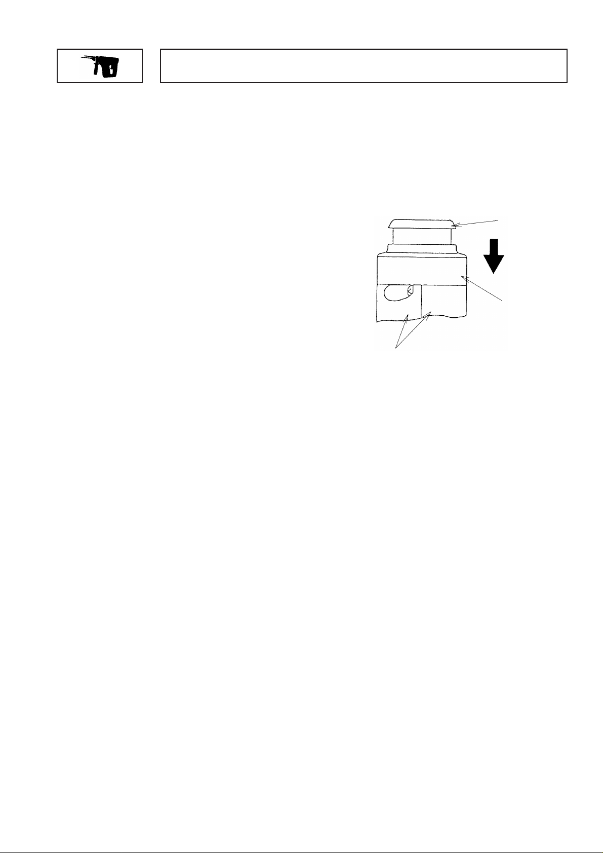
(1) Disassembly of the chuck section
As shown in Fig. 1, slide the Grip [2] in the direction
indicated by the arrow mark, and remove the Front Cap
[1]. The Grip [2], the Ball Holder [3] inside the Grip,
Holder Spring [4] and two Steel Balls [9] can then be
removed from the Cylinder [11].
(2) Disassembly of the housing
After removing the chuck section, loosen and remove the nine D4 x20 Tapping Screws (Black) [33] and
the two D4 x14 Tapping Screws [32] which fix the main body. Then, separate the Housing (A)(B) Set
[31] by removing Housing (B) from Housing (A).
(3) Disassembly of the hammering mechanism section
When the Cylinder [11] and the Piston [21] are removed from Housing (A) in a single body, the arm of
the Reciprocating Bearing [40] will be extracted from the Piston [21]. Then extract the Piston [21] from
the Cylinder [11], and with a screwdriver or slender rod push the Second Hammer [16] out through the
hole in the tip end of the Cylinder [11] to disconnect the Striker [19] retained by O-Ring (D) [18].
Pull out the First Gear [44] without the bearing from the Second Pinion [36]. Then remove the Collar
[41] and the Reciprocating Bearing [40]. Next, move the Clutch [38] toward the pinion side at the top of
the Second Pinion [36], and remove the O-Ring [39]. The Clutch [38] and the Clutch Spring [37] can
then be removed from the Second Pinion [36]. Remove the Retaining Ring for D14 Shaft [50] which
fixes the Change Lever [46] on the inner side of Housing (A), and extract the Change Lever [46] from
Housing (A). Be very careful not to lose the D3.97 Steel Ball [48].
(4) Disassembly of the cylinder and the second gear (slip mechanism section)
Extract the Retaining Ring [5] from the Cylinder [11]. Pull the Oil Seal [6] off of the Cylinder [11].
Extract the Retaining Ring for D20 Shaft [7], and remove the 6904CM Ball Bearing [8] from the Cylinder
[11] with a bearing puller. Be very careful not to lose the four D5.556 Steel Balls [10]. The Second
Gear [12], Spring (A) [13] and Washer (A) [14] can then be removed from the Cylinder [11]. Extract O-
Ring (D) [18] from deep within the Cylinder [11], and remove the Second Hammer [16] from the Cylinder
[11]. [O-Ring (D) can be easily removed by using the J-201 spring hook (Code No. 970977 is
recommended) to pull it out from the outside.] To prevent idle hammering, be sure to replace O-Ring
(D) [18] whenever the unit is disassembled.
Fig. 1
Front Cap [1]
Grip [2]
Housing (A),(B) Set [31]
MODEL DH 20DV

--- 2 ---
(5) Disassembly of the switch and the terminal
Remove Housing (B) and pull out the Internal Wires [54] [55] from Brush Holder (L) [59] and (R) [60].
Then the Terminals [66] [68], the Switch [53] and the Internal Wires [54] [55] can be removed together.
Perform the following procedure for disassembly of the Terminals [66] [68], the Switch [53] and the
Internal Wires [54] [55].
Disconnect the Internal Wires [54] (red) and [55] (black), and the Terminals [66] (brown) and [68] (blue)
from the Switch [53] by melting their soldered connections with a soldering iron (350 ˚C, within 5
seconds). Take care not to apply too much heat because it can damage the variable-speed function of
the switch. Remove the two D4 Tapping Screws [65] from the Terminals [66] [68].
(6) Removal of the rubber seal
Pull out Rubber Seal (A) [63] gently from the Oil Seal [6] on the housing ass'y. Pull out Rubber Seal (B)
[64] by sliding with your fingers. Take care not to scratch the rubber seals to prevent grease leakage.
(7) Removal of the armature and the magnet
Hook the spring of Brush Holder (L) [59] and Brush Holder (R) [60] on the edge of each Brush Holder.
Then remove the Armature [28] and the Magnet [29] together.
(8) Removal of the brash holders
Remove the two D3 Tapping Screws [58] from both sides of Brush Holder (L) [59] and also Brush Holder
(R) [60] (four in total). Then Brush Holders can be removed.
(9) Replacement of the carbon brushes
Remove the Armature [28] and the Magnet [29] together according to the step (7). Pull out each
terminal of the Carbon Brushes [57] from the brush holder terminal with a small flat-blade screwdriver,
and then remove the Carbon Brushes by pulling them inward. Push each terminal of the new Carbon
Brushes in the Brush Holder as far as it will go. Be careful not to contact the spring of the Brush Holder
with the wire of the Carbon Brush (pay attention to inserting orientation of the Carbon Brush) or not to
hook the spring on the edge of the Brush Holder. Thus, the two Carbon Brushes can be replaced.
1-1-2. Reassembly
Reassembly can be generally be carried out as the reverse of the disassembly procedures, with some items
to be noted as follows:
(1) Be sure to perform wiring connection as indicated in Fig. 2.
(2) Pay attention to the polarity of the Terminal Piece [67], and the Internal Wires [54] and [55] when
mounting them to Housing (A). Be careful that the blue and brown Internal Wires cross at the midpoint.
(3) Insert the Armature [28] into the Magnet [29] facing its no-notch side inward. Be careful not to scratch
the Armature [28] because the magnet attracts the Armature [28].
(4) Position the Washer [43] between the wall of Housing (A) and the V-ring [42] when mounting the
Second Pinion [36] to the main body. Be careful not to position the Washer [43] between the wall of
Housing (A) and the First Gear [44].

--- 3 ---
Red
Upper side black
Lower side red
Upper side blue
Lower side brown
Upper side brown
Lower side blue
D4x14 Tapping Screw [32]
(2 pcs.)
Washer [43]
Detail drawing
V-ring [42]
Washer [43]
First Gear [44]
Wall of housing (A)
Switch [53]
Application silicon rubber (Three Bond 1211) ( Code No. 306927)
Fig. 2 Wiring arrangement and port locations
Fig. 3 Installation direction of various parts
First Gear [44]
Collar [41]
Press fit the First Gear [44]
so that their surfaces are
evenly aligned
The closed side of
Washer (C) [23] must
face forward
Forward
The shorter dimension L side
of the Second Hammer [16]
must face forward.
L

--- 4 ---
(5) When installing Washer (C) [23] and the Second Hammer [16], be very careful to ensure they are
installed in the proper direction. (See Fig. 3)
(6) When pressure fitting the First Gear [44], ensure that its surface is flush with the surface of the Second
Pinion [36]. At this time, also check to ensure that there is a slight clearance between the Collar [41]
and the First Gear [44] to allow the Collar to rotate. (See Fig. 3)
(7) During reassembly, coat JF-375 grease on the following places. Also insert 50 g of JF-375 (Code No.
930037) grease around the Reciprocating Bearing [40].
The gear teeth of the pinion on the motor, the gear teeth of the First Gear [44], the teen of the Second
Pinion [36], the sliding portions of the Clutch [38] and the Reciprocating Bearing [40], the outer
circumference of the Second Hammer [16], O-Ring (B) [17] mounted on the Second Hammer [16], the
outer circumference of the Piston [21], the outer circumference of the Striker [19], O-Ring (A) [20]
mounted on the Striker [19], the gear teeth and claw portions of the Second Gear [12], the inner
surface of the Metal [24], the lip portion of the Oil Seal [6], the outer circumference and hole portion of
the Piston Pin [22], the pin portion, thin portion and O-ring portion of the Change Lever [46], the outer
circumference of the groove on the Clutch [38], the inner surface of the Cylinder [11], and the O-Ring
[49]. Also, coat NPC SEP-3A when reassembling the Steel Balls [9], [10] and [48].
(8) When installing the two D4 x14 Tapping Screws [32], be very careful not to install the D4 x20 Tapping
Screws (W/Flange) [33] (black color) by mistake. Their positions are clearly designated in
Fig. 2.
(9) Tightening Torque
Tighten screws to the designated torque.
D3 x10 Tapping Screws [58]
••••••••••••••••••••••••••••
10.5 ---- 13.5 kgf•cm (1.03 ---- 1.32 N•m, 9 ---- 12 in•lbs)
D4 x10 Tapping Screws [65]
••••••••••••••••••••••••••••
15 ---- 25 kgf•cm (1.47 ---- 2.45 N•m, 13 ---- 22 in•lbs)
D4 x14 Tapping Screws [32]
••••••••••••••••••••••••••••
17 ---- 27 kgf•cm (1.67 ---- 2.65 N•m, 15 ---- 23 in•lbs)
D4 x20 Tapping Screws [33]
••••••••••••••••••••••••••••
20 ---- 30 kgf•cm (1.96 ---- 2.94 N•m, 17 ---- 26 in•lbs)
(10) On completion of reassembly, confirm without fail that the rotation direction conforms to the push-
button setting indications. When the push-button is set to the (R) side, the rotation direction must be
clockwise when viewed from the rear (handle) end of the tool.
1-2. Precautions on Disassembly and Reassembly of the Charger
Please refer to Technical Data and Service Manual for Model UC 24YF for precautions on disassembly and
reassembly.

--- 5 ---
2. STANDARD REPAIR TIME (UNIT) SCHEDULES
MODEL
Fixed
10 20 30 40 50 60 min.
Variable
DH 20DV
Oil Seal
Ball Bearing
(6904CM)
Steel Ball x4
Second Gear
Spring (A)
Washer (A)
O-ring (D)
Second Hammer
Cylinder
Piston
Striker
Piston Pin
Washer (C)
Metal
Ball Bearing
(626VV) x2
Second Pinion
Clutch Spring
Clutch
O-ring
Reciprocating
Bearing
Collar
First Gear
Washer (B)
x
2
Housing
(A) (B) Set
Armature DC
Magnet
Switch
Rubber Seal (A)
Rubber Seal (B)
Change Lever
Spring (H)
Steel Ball
O-Ring
Carbon Brush
x
2
Brush Holder
x
2
Slide Lever
Spring
Plate
Front Cap
Grip
Retaining Ring
Work Flow
General Assembly
 Loading...