

Hitachi Deskstar T7K500, HDT725025VLA380, HDT725030VLAT80, HDT725025VLAT80, HDT725025VLA360 Specifications
...
Hard Disk Drive Specification
Deskstar T7K500
3.5 inch hard disk drive
Models:
HDT725025VLAT80
HDT725025VLA380
HDT725025VLA360
HDT725030VLAT80
HDT725030VLA380
HDT725030VLA360
HDT725032VLAT80
HDT725032VLA380
HDT725032VLA360
HDT725040VLAT80
HDT725040VLA380
HDT725040VLA360
HDT725050VLAT80
HDT725050VLA380
HDT725050VLA360
Version 1.2 06 December 2006

1st Edition (Revision 0.1) (20 August 2006)
2nd Edition (Revision 1.0) (06 September 2006
3rd Edition (Revision 1.1) (08 September 2006)
4th Edition (Revision 1.2) (06 December 2006)
The following paragraph does not apply to the United Kingdom or any country where such provisions are
inconsistent with local law: HITACHI GLOBAL STORAGE TECHNOLOGIES PROVIDES THIS PUBLICATION "AS IS" WITHOUT WARRANTY OF ANY KIND, EITHER EXPRESS OR IMPLIED, INCLUDING, BUT NOT LIMITED TO, THE IMPLIED WARRANTIES OF MERCHANTABILITY OR FITNESS
FOR A PARTICULAR PURPOSE. Some states do not allow disclaimer or express or implied warranties in
certain transactions, therefore, this statement may not apply to you.
This publication could include technical inaccuracies or typographical errors. Changes are periodically made to the
information herein; these changes will be incorporated in new editions of the publication. Hitachi may make
improvements or changes in any products or programs described in this publication at any time.
It is possible that this publication may contain reference to, or information about, Hitachi products (machines and
programs), programming, or services that are not announced in your country. Such references or information must
not be construed to mean that Hitachi intends to announce such Hitachi products, programming, or services in your
country.
Technical information about this product is available by contacting your local Hitachi Global Storage Technologies
representative or on the Internet at
http://www.hitachigst.com
Hitachi Global Storage Technologies may have patents or pending patent applications covering subject matter in this
document. The furnishing of this document does not give you any license to these patents. ©Copyright Hitachi Global Storage Technologies
Note to U.S. Government Users - Documentation related subject to restricted rights - Use, duplication or disclosure is
subject to restrictions set forth in GSA ADP Schedule Contract with Hitachi Global Storage Technologies Inc.

Table of Contents
1.0. General.........................................................................................................................1
1.1. Introduction........................................................................................................... 1
1.2. References............................................................................................................. 1
1.3. Abbreviations........................................................................................................ 1
1.4. Caution.................................................................................................................. 3
2.0. General features of the drive .....................................................................................5
3.0. Fixed-disk subsystem description..............................................................................9
3.1. Control electronics................................................................................................ 9
3.2. Head disk assembly ............................................................................................. 9
3.3. Actuator ................................................................................................................ 9
4.0. Drive characteristics.................................................................................................11
4.1. Default logical drive parameters......................................................................... 11
4.2. Data sheet............................................................................................................ 13
4.3. World Wide Name Assignment.......................................................................... 13
4.4. Drive organization.............................................................................................. 13
4.4.1 Drive format ..............................................................................................13
4.4.2 Cylinder allocation ....................................................................................14
4.5. Performance characteristics................................................................................ 15
4.5.1 Command overhead ...................................................................................15
4.5.2 Mechanical positioning .............................................................................15
4.5.3 Drive ready time ........................................................................................17
4.5.4 Operating modes ........................................................................................17
5.0. Defect flagging strategy............................................................................................19
6.0. Electrical interface specification..............................................................................21
6.1. Connector location .............................................................................................. 21
6.1.1 4 pin DC power connector .........................................................................22
6.1.2 AT signal connector ..................................................................................22
6.2. Signal definitions (PATA model)....................................................................... 23
6.3. Signal descriptions .............................................................................................. 24
6.4. Interface logic signal levels (pata model)........................................................... 27
6.5. Signal definition (SATA model) ........................................................................ 27
6.5.1 TX+ / TX- ..................................................................................................27
6.5.2 RX+ / RX- .................................................................................................28
6.5.3 Out of band signaling (SATA model) .......................................................28
6.6. Reset timings ...................................................................................................... 29
6.7. PIO timings......................................................................................................... 30
6.7.1 Write DRQ interval time ...........................................................................30
6.7.2 Read DRQ interval time ............................................................................30
6.8. Multi-word DMA timings................................................................................... 31
6.9. Ultra DMA timings ............................................................................................. 32
6.9.1 Initiating Read DMA .................................................................................32
6.9.2 Host Pausing Read DMA ..........................................................................33

6.9.3 Host Terminating Read DMA ...................................................................34
6.9.4 Device Terminating Read DMA ...............................................................35
6.9.5 Initiating Write DMA ................................................................................36
6.9.6 Device Pausing Write DMA ......................................................................37
6.9.7 Device Terminating Write DMA ...............................................................38
6.9.8 Host Terminating Write DMA ..................................................................39
6.10. Addressing of registers..................................................................................... 40
6.10.1 Cabling ....................................................................................................40
7.0. Specification ..............................................................................................................43
7.1. Jumper settings ................................................................................................... 43
7.1.1 Jumper pin location ...................................................................................43
7.1.2 Jumper pin identification ...........................................................................43
7.1.3 Jumper pin assignment ..............................................................................43
7.1.4 Jumper positions ........................................................................................45
7.2. Environment ....................................................................................................... 49
7.2.1 Temperature and humidity ........................................................................49
7.2.2 Corrosion test .............................................................................................50
7.3. DC power requirements...................................................................................... 50
7.3.1 Input voltage ..............................................................................................51
7.3.2 Power supply current (typical) ..................................................................52
7.3.3 Power supply generated ripple at drive power connector .........................53
7.4. Reliability ........................................................................................................... 55
7.4.1 Data integrity .............................................................................................55
7.4.2 Cable noise interference ............................................................................55
7.4.3 Start/stop cycles .........................................................................................55
7.4.4 Preventitive Maintenance ..........................................................................55
7.4.5 Data reliability ...........................................................................................55
7.4.6 Required power-off sequence ....................................................................55
7.5. Mechanical specifications................................................................................... 56
7.5.1 Physical dimensions and weight ................................................................56
7.5.2 Mounting hole locations ............................................................................58
7.5.3 Connector locations ...................................................................................59
7.5.4 Drive mounting ..........................................................................................60
7.5.5 Heads unload and actuator lock .................................................................60
7.6. Vibration and shock............................................................................................ 61
7.6.1 Operating vibration ....................................................................................61
7.6.2 Nonoperating vibration ..............................................................................61
7.6.3 Operating shock .........................................................................................62
7.6.4 Nonoperating shock ...................................................................................62
7.6.5 Nonoperating rotational shock ..................................................................62
7.7. Acoustics............................................................................................................. 63
7.8. Identification labels ............................................................................................ 63
7.9. Safety.................................................................................................................. 64
7.9.1 UL and CSA approval ...............................................................................64
7.9.2 German safety mark ..................................................................................64
7.9.3 Flammability ..............................................................................................64

7.9.4 Safe handling .............................................................................................64
7.9.5 Environment ..............................................................................................64
7.9.6 Secondary circuit protection ......................................................................64
7.10. Electromagnetic compatibility.......................................................................... 65
7.10.1 CE Mark ..................................................................................................65
7.10.2 C-TICK mark ...........................................................................................65
7.10.3 BSMI mark ..............................................................................................65
7.10.4 MIC Mark ................................................................................................65
7.11. Packaging.......................................................................................................... 65
7.11.1 Substance restriction requirements ..........................................................65
8.0. General.......................................................................................................................67
8.1. Introduction......................................................................................................... 67
8.2. Terminology ....................................................................................................... 67
8.3. Deviations from standard.................................................................................... 67
9.0. Registers .....................................................................................................................69
9.1. Register set.......................................................................................................... 69
9.2. Alternate Status Register .................................................................................... 70
9.3. Command Register ............................................................................................. 70
9.4. Cylinder High Register....................................................................................... 70
9.5. Cylinder Low Register........................................................................................ 70
9.6. Data Register ...................................................................................................... 71
9.7. Device Control Register .................................................................................... 71
9.8. Drive Address Register....................................................................................... 72
9.9. Device/Head Register......................................................................................... 72
9.10. Error Register.................................................................................................... 73
9.11. Features Register .............................................................................................. 73
9.12. Sector Count Register....................................................................................... 73
9.13. Sector Number Register.................................................................................... 74
9.14. Status Register.................................................................................................. 74
10.0. General operation...................................................................................................77
10.1. Reset response .................................................................................................. 77
10.2. Register initialization ........................................................................................ 78
10.3. Diagnostic and Reset considerations................................................................ 79
10.4. Sector Addressing Mode................................................................................... 80
10.4.1 Logical CHS addressing mode ................................................................80
10.4.2 LBA addressing mode .............................................................................80
10.5. Power management features............................................................................. 81
10.5.1 Power mode .............................................................................................81
10.5.2 Power management commands ...............................................................81
10.5.3 Standby timer ...........................................................................................81
10.5.4 Interface capability for power modes ......................................................82
10.6. S.M.A.R.T. Function ........................................................................................ 83
10.6.1 Attributes .................................................................................................83
10.6.2 Attribute values .......................................................................................83
10.6.3 Attribute thresholds .................................................................................83
10.6.4 Threshold exceeded condition .................................................................83

10.6.5 S.M.A.R.T. commands ............................................................................83
10.6.6 Off-line read scanning .............................................................................83
10.6.7 Error log ...................................................................................................84
10.6.8 Self-test ....................................................................................................84
10.7. Security Mode Feature Set................................................................................ 85
10.7.1 Security mode ..........................................................................................85
10.7.2 Security level ...........................................................................................85
10.7.3 Passwords ................................................................................................86
10.7.4 Operation example ...................................................................................86
10.7.5 Command table ........................................................................................90
10.8. Host Protected Area Feature............................................................................. 92
10.8.1 Example for operation (In LBA Mode) ...................................................92
10.8.2 Security extensions ..................................................................................93
10.9. Seek overlap...................................................................................................... 94
10.10. Write cache function....................................................................................... 95
10.11. Reassign function............................................................................................ 96
10.11.1 Auto Reassign function .........................................................................96
10.12. Power-Up in Standby feature set.................................................................... 97
10.13. Advanced Power Management feature set (APM)......................................... 98
10.14. Automatic Acoustic Management feature set (AAM).................................... 99
10.15. Address Offset Feature................................................................................. 100
10.15.1 Enable/Disable Address Offset Mode .................................................100
10.15.2 Identify Device Data ............................................................................101
10.15.3 Exceptions in Address Offset Mode ...................................................101
10.16. 48-bit Address Feature Set............................................................................ 102
10.17. Streaming feature Set.................................................................................... 102
10.17.1 Streaming commands ..........................................................................103
10.17.2 Urgent bit .............................................................................................103
10.17.3 Flush to Disk bit ..................................................................................103
10.17.4 Not Sequential bit ................................................................................103
10.17.5 Read Continuous bit ............................................................................104
10.17.6 Write Continuous bit ...........................................................................104
10.17.7 Handle Streaming Error bit .................................................................104
10.17.8 Streaming Logs ....................................................................................104
10.18. SCT Command Transport Feature Set.......................................................... 104
10.18.1 SCT Command Protocol ......................................................................105
10.18.2 SCT Command Set ..............................................................................111
11.0. Command protocol ...............................................................................................123
11.1. PIO Data In commands................................................................................... 123
11.2. PIO Data Out Commands............................................................................... 124
11.3. Non-data commands...................................................................................... 126
11.4. DMA commands............................................................................................. 127
12.0. Command descriptions.........................................................................................129
12.1. Check Power Mode (E5h/98h) ....................................................................... 134
12.2. Configure Stream (51h).................................................................................. 135
12.3. Device Configuration Overlay (B1h) ............................................................. 137

12.3.1 DEVICE CONFIGURATION RESTORE (Subcommand C0h) .........137
12.3.2 DEVICE CONFIGURATION FREEZE LOCK (subcommand C1h) ..137
12.3.3 DEVICE CONFIGURATION IDENTIFY (subcommand C2h) .........138
12.3.4 DEVICE CONFIGURATION SET (subcommand C3h) ......................138
12.4. Download Microcode (92h)............................................................................ 141
12.5. Execute Device Diagnostic (90h)................................................................... 142
12.6. Flush Cache (E7h) .......................................................................................... 143
12.7. Flush Cache Ext (EAh)................................................................................... 144
12.8. Format Track (50h)......................................................................................... 145
12.9. Format Unit (F7h)........................................................................................... 147
12.10. Identify Device (ECh)................................................................................... 148
12.11. Idle (E3h/97h).............................................................................................. 159
12.12. Idle Immediate (E1h/95h)............................................................................. 160
12.13. Initialize Device Parameters (91h) ............................................................... 161
12.14. Read Buffer (E4h)......................................................................................... 162
12.15. Read DMA (C8h/C9h).................................................................................. 163
12.16. Read DMA Ext (25h).................................................................................... 165
12.17. Read Log Ext (2Fh)...................................................................................... 167
12.17.1 General Purpose Log Directory ...........................................................169
12.17.2 Extended Comprehensive SMART Error Log ....................................170
12.17.3 Extended Self-test log sector ...............................................................172
12.17.4 Read Stream Error Log ........................................................................173
12.17.5 Write Stream Error Log .......................................................................175
12.17.6 Streaming Performance Log ................................................................176
12.18. Read Long (22h/23h).................................................................................... 178
12.19. Read Multiple (C4h)..................................................................................... 180
12.20. Read Multiple Ext (29h)............................................................................... 181
12.21. Read Native Max ADDRESS (F8h)............................................................. 183
12.22. Read Native Max Address Ext (27h)............................................................ 184
12.23. Read Sectors (20h/21h)................................................................................. 185
12.24. Read Sector(s) Ext (24h) .............................................................................. 187
12.25. Read Stream DMA (2Ah)............................................................................. 189
12.26. Read Stream PIO (2Bh)................................................................................ 193
12.27. Read Verify Sectors (40h/41h)..................................................................... 196
12.28. Read Verify Sectors Ext (42h)...................................................................... 198
12.29. Recalibrate (1xh) .......................................................................................... 200
12.30. Security Disable Password (F6h).................................................................. 201
12.31. Security Erase Prepare.................................................................................. 202
12.32. Security Erase Unit (F4h)............................................................................. 203
12.33. Security Freeze Lock (F5h).......................................................................... 205
12.34. Security Set Password (F1h)......................................................................... 206
12.35. Security Unlock (F2h) .................................................................................. 208
12.36. Seek (7xh).................................................................................................... 210
12.37. Set Features (EFh) ........................................................................................ 211
12.37.1 Set Transfer mode ................................................................................212
12.37.2 Write Cache .........................................................................................212

12.37.3 Advanced Power Management ............................................................212
12.37.4 Automatic Acoustic Management .......................................................214
12.38. Set Max ADDRESS (F9h)............................................................................ 215
12.38.1 Set Max Set Password (Feature=01h) .................................................217
12.38.2 Set Max Lock (Feature=02h) ..............................................................218
12.38.3 Set Max Unlock (Feature = 03h) .........................................................219
12.38.4 Set Max Freeze Lock (Feature = 04h) .................................................220
12.39. Set Max Address Ext (37h)........................................................................... 221
12.40. Set Multiple (C6h)........................................................................................ 223
12.41. Sleep (E6h/99h)............................................................................................ 224
12.42. S.M.A.R.T. Function Set (B0h).................................................................... 225
12.42.1 S.M.A.R.T. Function Subcommands ..................................................226
12.42.2 Device Attribute Data Structure ..........................................................230
12.42.3 Device Attribute Thresholds data structure .........................................233
12.42.4 S.M.A.R.T. Log Directory ...................................................................235
12.42.5 S.M.A.R.T. summary error log sector .................................................235
12.42.6 Self-test log data structure ..................................................................237
12.42.7 Selective self-test log data structure ....................................................238
12.42.8 Error reporting .....................................................................................239
12.43. Standby (E2h/96h)........................................................................................ 241
12.44. Standby Immediate (E0h/94h)...................................................................... 243
12.45. Write Buffer (E8h)........................................................................................ 244
12.46. Write DMA (CAh/CBh)............................................................................... 245
12.47. Write DMA Ext (35h)................................................................................... 247
12.48. Write DMA FUA Ext (3Dh)......................................................................... 249
12.49. Write Log Ext (3Fh) ..................................................................................... 251
12.50. Write Long (32h/33h)................................................................................... 252
12.51. Write Multiple (C5h).................................................................................... 254
12.52. Write Multiple Ext (39h).............................................................................. 256
12.53. Writer Multiple FUA Ext (CEh)................................................................... 258
12.54. Write Sectors (30h/31h)................................................................................ 260
12.55. Write Sector(s) Ext (34h).............................................................................. 262
12.56. Write Stream DMA (3Ah)............................................................................ 264
12.57. Write Stream PIO (3Bh)............................................................................... 266
13.0. Timings ..................................................................................................................269

List of Tables
Table 1: Formatted capacities.....................................................................................11
Table 2: Mechanical positioning performance ...........................................................13
Table 3: Word Wide Name Assignment.....................................................................13
Table 4: Command overhead......................................................................................15
Table 5: Mechanical positioning performance ...........................................................15
Table 6: Full stroke seek time.....................................................................................16
Table 7: Single track seek time...................................................................................16
Table 8: Latency Time................................................................................................17
Table 9: Drive ready time...........................................................................................17
Table 10: Description of operating modes..................................................................17
Table 11: Mode transition times.................................................................................18
Table 12: PATA Plist physical format........................................................................19
Table 13: Signal definitions........................................................................................23
Table 14: Special signal definitions for Ultra DMA ..................................................24
Table 15: System reset timing chart ...........................................................................29
Table 16: System reset timing ....................................................................................29
Table 17: PIO cycle timings chart ..............................................................................30
Table 18: Multiword DMA cycle timing chart...........................................................31
Table 19: Multiword DMA cycle timings ..................................................................31
Table 20: Ultra DMA cycle timings (Initiating Read)................................................32
Table 21: Ultra DMA cycle timing chart (Host pausing Read)..................................33
Table 22: Ultra DMA cycle timings (Host pausing Read) .........................................33
Table 23: Ultra DMA cycle timing chart (Host pausing Read)..................................34
Table 24: Ultra DMA cycle timings (Host pausing Read) .........................................34
Table 25: Ultra DMA cycle timing chart (Host pausing Read)..................................35
Table 26: Ultra DMA cycle timings (Device Terminating Read)..............................35
Table 27: Ultra DMA cycle timing chart (Initiating Write) .......................................36
Table 28: Ultra DMA cycle timing chart (Device Pausing Write).............................37
Table 29: Ultra DMA cycle timings (Device Pausing Write) ....................................37
Table 30: Ultra DMA cycle timing chart (Device Terminating Write)......................38
Table 31: Ultra DMA cycle timings (Device TerminatingWrite) ..............................38
Table 32: Ultra DMA cycle timing chart (Host Terminating Write)..........................39
Table 33: Ultra DMA cycle timings (Host Terminating Write).................................39
Table 34: I/O address map..........................................................................................40
Table 35: Jumper positions for capacity clip to 32GB ...............................................47
Table 36: Jumper settings for Disabling Auto Spin....................................................47
Table 37: Temperature and humidity .........................................................................49
Table 38: Limits of temperature and humidity...........................................................50
Table 39: Input voltage...............................................................................................51
Table 40: Power supply current of 80GB and 40GB models.....................................52
Table 41: Power supply generated ripple at drive power connector ..........................53
Table 42: Random vibration PSD...............................................................................61
Table 43: Random vibration PSD profile break points (operating) ............................61

Table 44: Random Vibration PSD profile breakpoints (nonoperating)......................61
Table 45: Sinusoidal shock wave ...............................................................................62
Table 46: Rotational shock .......................................................................................62
Table 47: Sound power levels.....................................................................................63
Table 48: Register Set .................................................................................................69
Table 49: Alternate Status Register............................................................................70
Table 50: Device Control Register .............................................................................71
Table 51: Drive Address Register...............................................................................72
Table 52: Device Head/Register.................................................................................72
Table 53: Error Register .............................................................................................73
Table 54: Status Register............................................................................................74
Table 55: Reset response table ...................................................................................77
Table 56: Default Register Values ..............................................................................78
Table 57: Diagnostic codes.........................................................................................78
Table 58: Reset error register values ..........................................................................79
Table 59: Power conditions ........................................................................................82
Table 60: Initial setting...............................................................................................87
Table 61: Usual operation for POR ............................................................................88
Table 62: Password lost..............................................................................................89
Table 63: Seek overlap ...............................................................................................94
Table 64: Device address map before and after Set Feature ....................................100
Table 65: Feature Code List .....................................................................................118
Table 66: Command Set ...........................................................................................129
Table 67: Command Set (subcommand) ..................................................................132
Table 68: Check Power Mode command (E5h/98h) ................................................134
Table 69: Configure Stream (51h)............................................................................135
Table 70: Check Power Mode Command (E5h/98h) ...............................................137
Table 71: Device Configuration Overlay Features register values...........................137
Table 72: Device Configuration Overlay Data structure..........................................139
Table 73: DCO error information definition ............................................................140
Table 74: Downlad Microcode Command (92h)......................................................141
Table 75: Execute Device Diagnostic command (90h)............................................142
Table 76: Flush Cache command (E7h) ...................................................................143
Table 77: Flush Cache Ext Command (EAh)...........................................................144
Table 78: Format Track command (50h)..................................................................145
Table 79: Format Unit command (F7h)....................................................................147
Table 80: Identify Device command (ECh)..............................................................148
Table 81: Identify device information .....................................................................149
Table 82: Identify device information......................................................................151
Table 83: Identify device information .....................................................................153
Table 84: Identify device information......................................................................154
Table 85: Identify device information......................................................................155
Table 86: Identify device information......................................................................156
Table 87: Idle command (E3h/97h)..........................................................................159
Table 88: Idle Immediate command (E1h/95h)........................................................160
Table 89: Initialize Device Parameters command (91h) ..........................................161

Table 90: Read Buffer (E4h) ....................................................................................162
Table 91: Read DMA command (C8h/C9h).............................................................163
Table 92: Read DMA Ext Command (25h)..............................................................165
Table 93: Read Log Ext Command (2Fh) ................................................................167
Table 94: Log Address Definition............................................................................168
Table 95: General Purpose Log Directory................................................................169
Table 96: Extended Comprehensive SMART Error Log .........................................170
Table 97: Extended Error log data structure.............................................................170
Table 98: Command data structure...........................................................................171
Table 99: Error data structure...................................................................................171
Table 100: Read Stream Error Log...........................................................................173
Table 101: Stream Error Log entry...........................................................................175
Table 102: Write Stream Error Log..........................................................................176
Table 103: Streaming Performance Parameters log .................................................177
Table 104: Sector Time Array Entry (Linearly Interpolated)...................................177
Table 105: Access Time Array Entry (Linearly Interpolated)..................................177
Table 106: Read Long (22h/23h)..............................................................................178
Table 107: Read Multiple (C4h)...............................................................................180
Table 108: Read DMA Ext Command (25h)............................................................181
Table 109: Read Native Max ADDRESS (F8h).......................................................183
Table 110: Read Native Max Address Ext command (27h).....................................184
Table 111: Read Sectors Command (20h/21h).........................................................185
Table 112: Read Sector(s) Ext command (24h) ......................................................187
Table 113: Read Stream DMA Command (2Ah).....................................................189
Table 114: Read Stream PIO (2Bh)..........................................................................193
Table 115: Read Verify Sectors (40h/41h)...............................................................196
Table 116: Read Verify Sectors Ext command (42h)...............................................198
Table 117: Recalibrate (1xh) ....................................................................................200
Table 118: Security Disable Password (F6h) ...........................................................201
Table 119: Password Information for Security Disable Password command ..........201
Table 120: Security Disable Password (F3h) ...........................................................202
Table 121: Security Erase Unit (F4h).......................................................................203
Table 122: Erase Unit information ...........................................................................203
Table 123: Security Freeze Lock command (F5h) ...................................................205
Table 124: Security Set Password command (F1h)..................................................206
Table 125: Security Set Password Information ........................................................206
Table 126: Security Unlock command (F2h) ...........................................................208
Table 127: Seek command (7xh)..............................................................................210
Table 128: Set Features command (EFh) .................................................................211
Table 129: Set Max ADDRESS command (F9h).....................................................215
Table 130: Set Max Set Password command ...........................................................217
Table 131: Set Max Set Password data contents ......................................................217
Table 132: Set Max Lock command.........................................................................218
Table 133: Set Max Unlock command (F9h) ...........................................................219
Table 134: Set Max Freeze Lock (F9h)....................................................................220
Table 135: Set Max Address Ext command (37h)....................................................221

Table 136: Set Multiple command (C6h).................................................................223
Table 137: Sleep command (E6h/99h) .....................................................................224
Table 138: S.M.A.R.T. Function Set command (B0h).............................................225
Table 139: Device Attribute Data Structure.............................................................230
Table 140: Individual Attribute Data Structure........................................................230
Table 141: Device Attribute Thresholds Data Structure ..........................................234
Table 142: Individual Threshold Data Structure ......................................................234
Table 143: S.M.A.R.T. Log Directory......................................................................235
Table 144: S.M.A.R.T. summary error log sector ..................................................235
Table 145: Error log data structure..........................................................................236
Table 146: Command data structure.........................................................................236
Table 147: Error data structure.................................................................................236
Table 148: Self-test log data structure......................................................................237
Table 149: Selective self-test log data structure.......................................................239
Table 150: S.M.A.R.T. Error Codes.........................................................................239
Table 151: Standby (E2h/96h)..................................................................................241
Table 152: Standby Immediate (E0h/94h) ................................................................243
Table 153: Write Buffer (E8h) .................................................................................244
Table 154: Write DMA (CAh/CBh).........................................................................245
Table 155: Write DMA Ext Command (35h)..........................................................247
Table 156: Write Log Ext Command (3Fh) ............................................................251
Table 157: Write Long (32h/33h).............................................................................252
Table 158: Write Multiple (C5h)..............................................................................254
Table 159: WriteMultiple Ext Command (39h) .......................................................256
Table 160: Write Sectors command (30h/31h).........................................................260
Table 161: Write Sectors Ext....................................................................................262
Table 162: Write Stream DMA Command (3Ah)....................................................264
Table 163: Write Stream PIO Command (3Bh) .......................................................266

1.0 General
1.1 Introduction
This document describes the specifications of the Deskstar T7K500, a 3.5-inch hard disk drive with ATA interface
and a rotational speed of 7200 RPM.
HDT725025VLAT80 / A380 / A360 250.0 GB
HDT725030VLAT80 / A380 / A360 300.0 GB
HDT725032VLAT80 / A380 / A360 320.0 GB
HDT725040VLAT80 / A380 / A360 400.0 GB
HDT725050VLAT80 / A380 / A360 500.0 GB
These specifications are subject to change without notice.
1.2 References
• Information Technology - AT Attachment with Packet Interface-7.
• Serial ATA II: Extensions to Serial ATA 1.0
1.3 Abbreviations
Abbreviation Meaning
AAmpere
AC alternating current
ADM Automatic Drive Maintenance
AT Advanced Technology
ATA Advanced Technology Attachment
BIOS Basic Input/Output System
C Celsius
CSA Canadian Standards Association
C-UL Canadian-Underwriters Laboratory
Cyl cylinder
DC Direct Current
DFT Drive Fitness Test
DMA Direct Memory Access
ECC error correction code
EEC European Economic Community
EMC electromagnetic compatibility
ERP Error Recovery Procedure
ESD E lectrostatic Discharge
Deskstar T7K500 Hard Disk Drive Specification
1

FCC Federal Com munications Commission
FRU field replacement unit
G gravity (a unit of force)
2
G
/Hz (32 ft/sec)2 per Hertz
Gb 1,000,000,000 bits
GB 1,000,000,000 bytes
GND ground
h hexadecimal
HDD hard disk drive
Hz Hertz
I Input
ILS integrated lead suspension
I/O Input/Output
ISO International Standards Organization
KB 1,000 bytes
Kbpi 1000 bits per inch
kgf-cm kilogram (force)-centimeter
KHz kilohertz
LBA logical block addressing
Lw unit of A-weighted sound power
mmeter
max maximum
MB 1,000 , 000 bytes
Mbps 1,000,000 bits per second
MHz megahertz
MLC Machine Level Control
mm millimeter
ms millisecond
us, ms microsecond
OOutput
OD Open Drain Programmed Input/Output
POH power on hours
Pop population
P/N part number
p-p peak-to-peak
PSD power spectral density
RES radiated electromagnetic susceptibility
RFI radio frequency interference
RH relative humidity
RMS root mea n square
RPM revolu tions per minute
RST reset
R/W read/write
Deskstar T7K500 Hard Disk Drive Specification
2

sec second
SELV secondary low voltage
S.M.A.R.TSelf-Monitoring, Analysis, and Reporting Technology
TPI tracks per inch
Trk track
TTL transistor-transistor logic
UL Underwriters Laboratory
Vvolt
VDE Verband Deutscher Electrotechniker
Wwatt
3-state transistor-transistor tristate logic
1.4 Caution
• Do not apply force to the top cover.
• Do not cover the breathing hole on the top cover.
• Do not touch the interface connector pins or the surface of the printed circuit board
• This drive can be damaged by electrostatic discharge (ESD). Any damages incurred to the drive after its
removal from the shipping package and the ESD protective bag are the responsibility of the user.
Deskstar T7K500 Hard Disk Drive Specification
3

Deskstar T7K500 Hard Disk Drive Specification
4

2.0 General features of the drive
• Formatted capacities of 250 GB to 500 GB
• Spindle speeds of 7200 RPM
• Fluid Dynamic Bearing motor
• Enhanced IDE interface
• Sector format of 512 bytes/sector
• Closed-loop actuator servo
• Load/Unload mechanism, non head disk contact start/stop
• Automatic Actuator lock
• Interleave factor 1:1
• Seek time of 8.8 ms in Read Operation. 8.5 ms typical without Command Overhead
• Sector Buffer size of 8192 K (Upper 292 KB is used for firmware)
• Ring buffer implementation
• Write Cache
• Native command queuing support (SATA model)
• Advanced ECC On The Fly (EOF)
• Automatic Error Recovery procedures for read and write commands
• Self Diagnostics on Power on and resident diagnostics
• PIO Data Transfer Mode 4 (16.6 MB/s)
• DMA Data Transfer
• Multiword mode Mode 2 (16.6 MB/s)
• Ultra DMA Mode 6 (133 MB/s)
• Serial ATA Data Transfer 3Gbps / 1.5Gbps
• CHS and LBA mode
• Power saving modes/Low RPM idle mode (APM)
• S.M.A.R.T. (Self Monitoring and Analysis Reporting Technology)
• Support security feature
• Quiet Seek mode (AAM)
• 48-bit addressing feature
• Adaptive BPI
• ATA-7 compliant
• UDMA 133 support
• Streaming feature set support
• World Wide Name
Note: For serial ATA model, please refer "Serial ATA Specification - Addendum."
Deskstar T7K500 Hard Disk Drive specification
5

Deskstar T7K500 Hard Disk Drive Specification
6

Part 1. Functional specification
Deskstar T7K500 Hard Disk Drive specification
7

Deskstar T7K500 Hard Disk Drive Specification
8

3.0 Fixed-disk subsystem description
3.1 Control electronics
The drive is electronically controlled by a microprocessor, several logic modules, digital/analog modules, and various drivers and receivers. The control electronics performs the following major functions:
• Controls and interprets all interface signals between the host controller and the drive.
• Controls read write accessing of the disk media, including defect management and error
recovery.
• Controls starting, stopping, and monitoring of the spindle.
• Conducts a power-up sequence and calibrates the servo.
• Analyzes servo signals to provide closed loop control. These include position error signal and
estimated velocity.
• Monitors the actuator position and determines the target track for a seek operation.
• Controls the voice coil motor driver to align the actuator in a desired position.
• Constantly monitors error conditions of the servo and takes corresponding action if an error
occurs.
• Monitors various timers such as head settle and servo failure.
• Performs self-checkout (diagnostics).
3.2 Head disk assembly
The head disk assembly (HDA) is assembled in a clean room environment and contains the disks and actuator
assembly. Air is constantly circulated and filtered when the drive is operational. Venting of the HDA is accomplished via a breather filter.
The spindle is driven directly by an in-hub, brushless, sensorless DC drive motor. Dynamic braking is used to
quickly stop the spindle.
3.3 Actuator
The read/write heads are mounted in the actuator. The actuator is a swing-arm assembly driven by a voice coil
motor . A closed-loop position ing servo controls the movement of the actuator. An embedded servo pattern supplies
feedback to the positioning servo to keep the read/write heads centered over the desired track.
The actuator assembly is balanced to allow vertical or horizontal mounting without adjustment.
When the drive is powered off, the actuator automatically moves the head to the actuator ramp outside of the disk
where it parks.
Deskstar T7K500 Hard Disk Drive Specification
9

Deskstar T7K500 Hard Disk Drive Specification
10
4.0 Drive characteristics
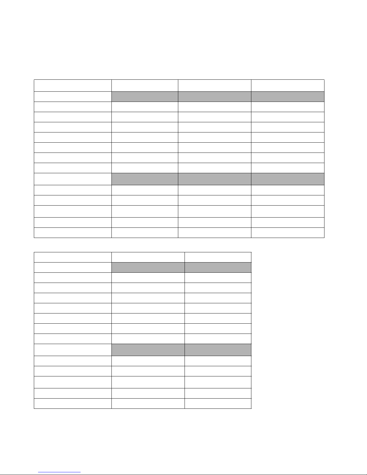
4.1 Default logical drive parameters
Table 1: Formatted capacities
Description
HDT725025VLxxxx
HDT725030VLxxxx
3
HDT725032VLxxxx
Physical Layout
Label capacity (GB) 250 300 320
Bytes per sector 512 512 512
Sectors per track 672-1280 720-1440 720-1440
Number of heads 4 4 4
Number of disks 2 2 2
Data sectors per cylinder 2688-5120 2880-5760 2880-5760
Data cylinders per zone 1664-7680 2432-8960 2432-8960
Logical layout
1
Number of heads 16 16 16
Number of Sectors per track 63 63 63
Number of Cylinders
2
16,383 16,383 16,383
Number of sectors 488,397,168 586,072,368 625,142,448
Total logical data bytes 250,059,350,016 300,069,052,416 320,072,933,376
Description
HDT725040VLxxxx HDT725050VLxxxx
Physical Layout
Label capacity (GB) 400 500
Bytes per sector 512 512
Sectors per track 672-1320 720-1500
Number of heads 6 6
Number of disks 3 3
Data sectors per cylinder 4032-7920 4320 - 9000
Data cylinders per zone 1792-8320 1792 - 8832
Logical layout
1
Number of heads 16 16
Number of Sectors per track 63 63
Number of Cylinders
2
16,383 16,383
Number of sectors 781,422,768 976,773,168
Total logical data bytes 400,088,457,216 500,107,862,016
Deskstar T7K500 Hard Disk Drive Specification
11

Notes:
1.
Number of cylinders: For drives with capacities greater than 8.45 GB the Identify Device information word 01
limits the number of cylinders to 16, 383 per the ATA specification.
2.
Logical layout: Logical layout is an imaginary drive parameter (that is, the number of heads) which is used to
access the drive from the system interface. The logical layout to Physical layout (that is, the actual Head and Sectors ) translation is done automatically in the drive. The default setting can be obtained by issuing an IDENTIFY
DEVICE command.
3.
The 300 GB model is capacity clip model of the 320 GB model.
Deskstar T7K500 Hard Disk Drive Specification
12
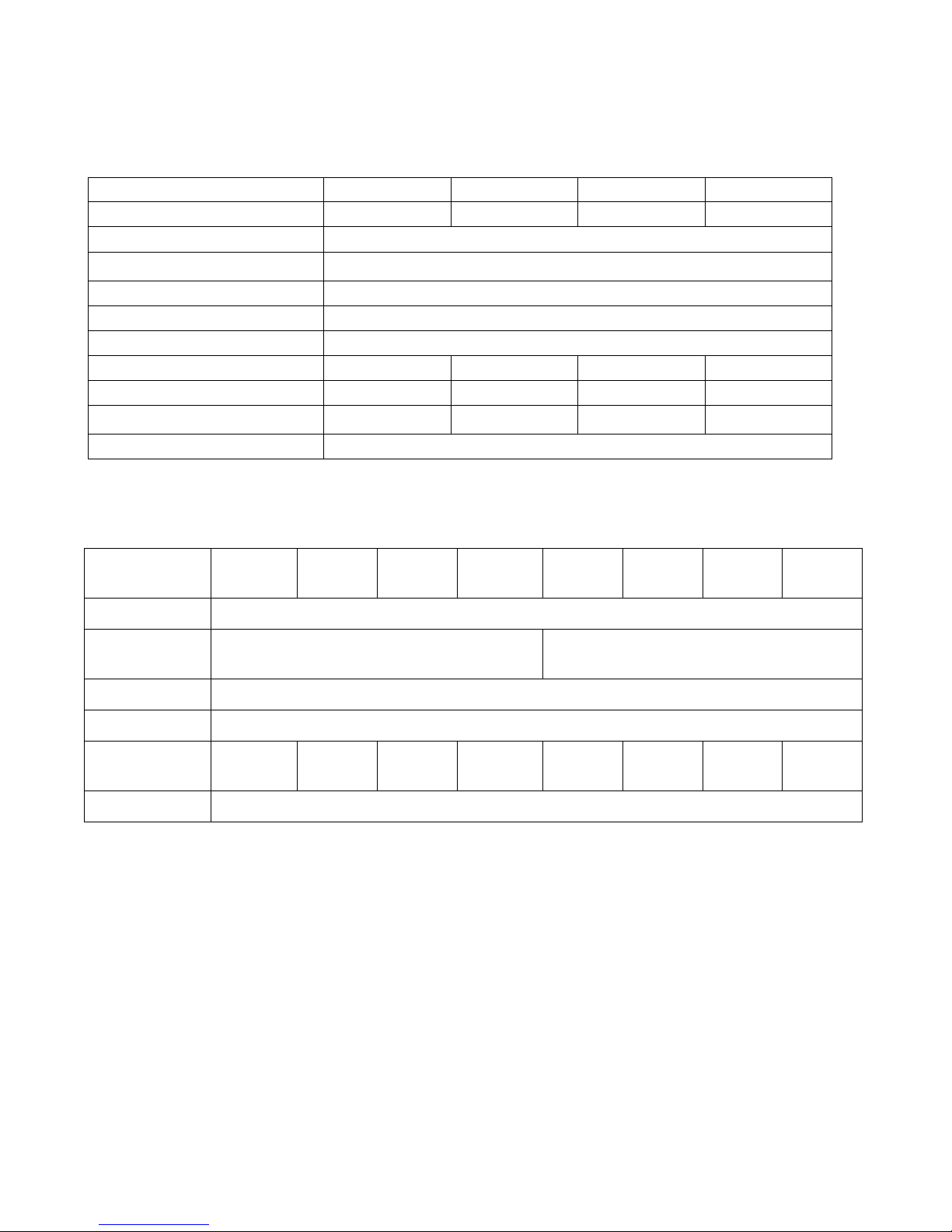
4.2 Data sheet
Table 2: Mechanical positioning performance
Description 250 GB 300/320 GB 400 GB 500 GB
Data transfer rates (Mbps) 824 957 848 998
Interface transfer rates (Mb/s) 133 (PATA) / 300 (SATA)
Data buffer size
Rotational speed (RPM) 7200
Number of buffer segments (read) up to 128
Number of buffer segments (write) up to 63
Recording density - max (Kbpi) 762 837 768 872
Track density [KTPI] 125 135 125 135
Areal density - max (Gbits/in
Number of data bands 30
1
(KB)
2
)
9511396118
8192 / 16384
4.3 World Wide Name Assignment
Table 3: Word Wide Name Assignment
Description
Organization Hitachi GST
Manufacturing
Site
Product Deskstar T7K500
OUI 000CCAh
SHBU Block
Assignment
Port/Node ID 11b
250 GB 300/320 GB400 GB 500 GB 250 GB 300/320 GB400 GB 500 GB
Sriracha Plant Thailand China Plant, China
210h 211h 212h 213h 310h 311h 312h 313h
4.4 Drive organization
4.4.1 Drive format
Upon shipment from manufacturing the drive satisfies the sector continuity in the physical format by means of the
defect flagging strategy described in Section 5.0, “Defect flagging strate gy” on page 21 in order to provide the
maximum performance to users.
Deskstar T7K500 Hard Disk Drive Specification
13
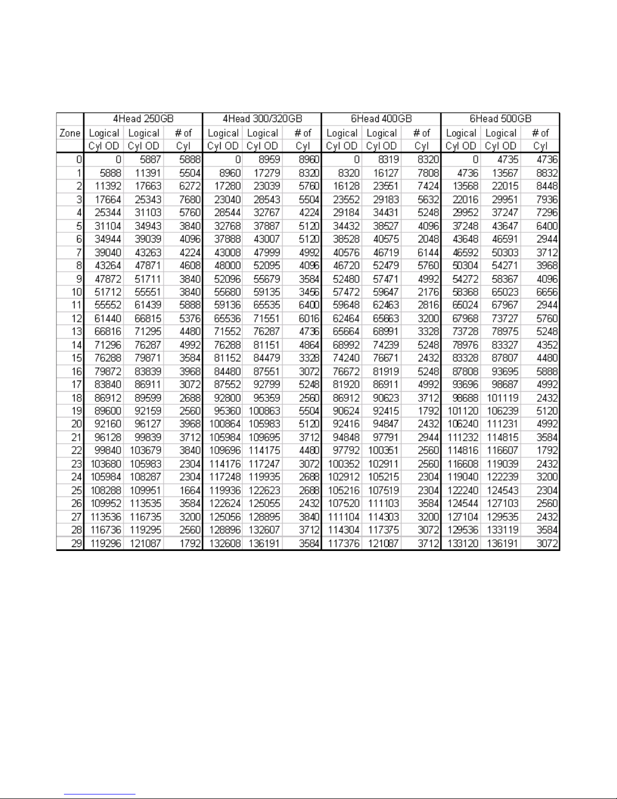
4.4.2 Cylinder allocation
Physical cylinder is calculated from the starting data track of 0. It is not relevant to logical CHS. Depending on the
capacity some of the inner zone cylinders are not allocated.
Data cylinder
This cylinder contains the user data which can be sent and retrieved via read/write commands and a spare area for
reassigned data.
Spare cylinder
The spare cylinder is used by Hitachi Global Storage Technologies manufacturing and includes data sent from a
defect location.
Deskstar T7K500 Hard Disk Drive Specification
14
4.5 Performance characteristics
Drive performance is characterized by the following parameters:
• Command overhead
• Mechanical head positioning
- Seek time
- Latency
• Data transfer speed
• Buffering operation (Look ahead/Write cache)
All the above parameters contribute to drive performance. There are other parameters that contribute to the performance of the actual system. This specification tries to define the bare drive characteristics, not system throughput,
which depends on the system and the application.
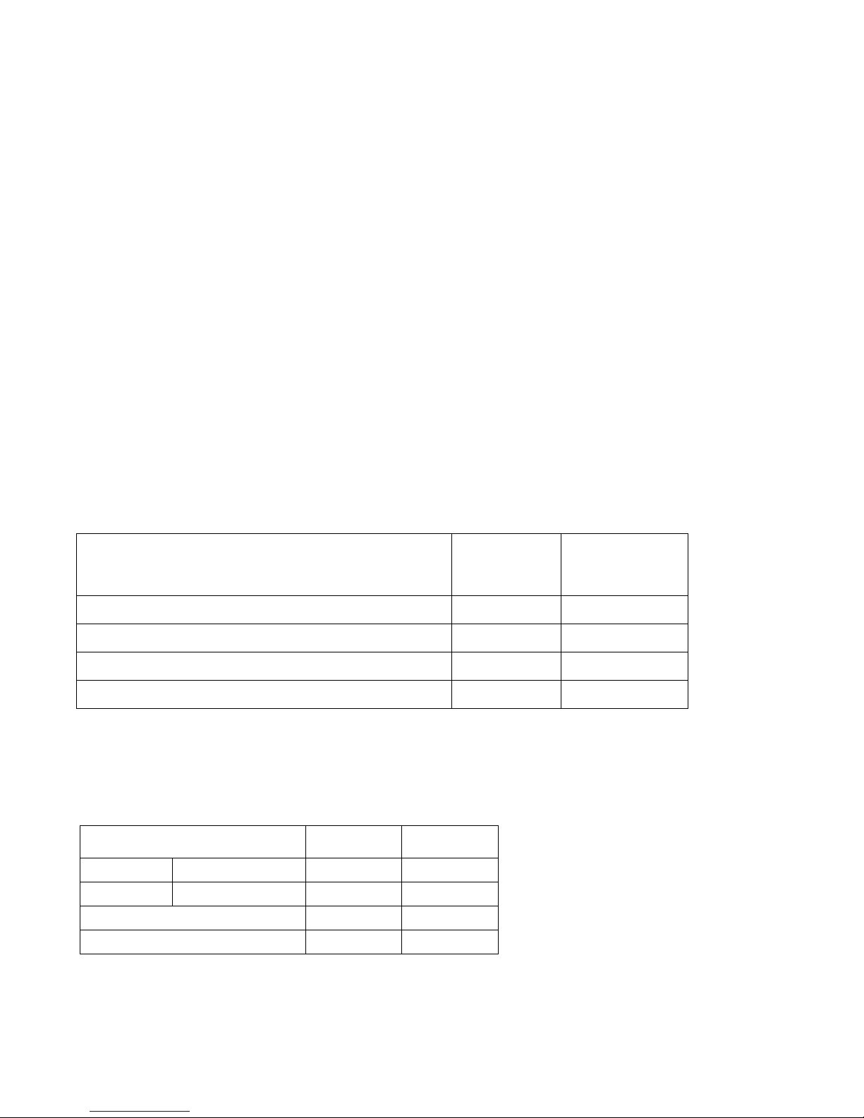
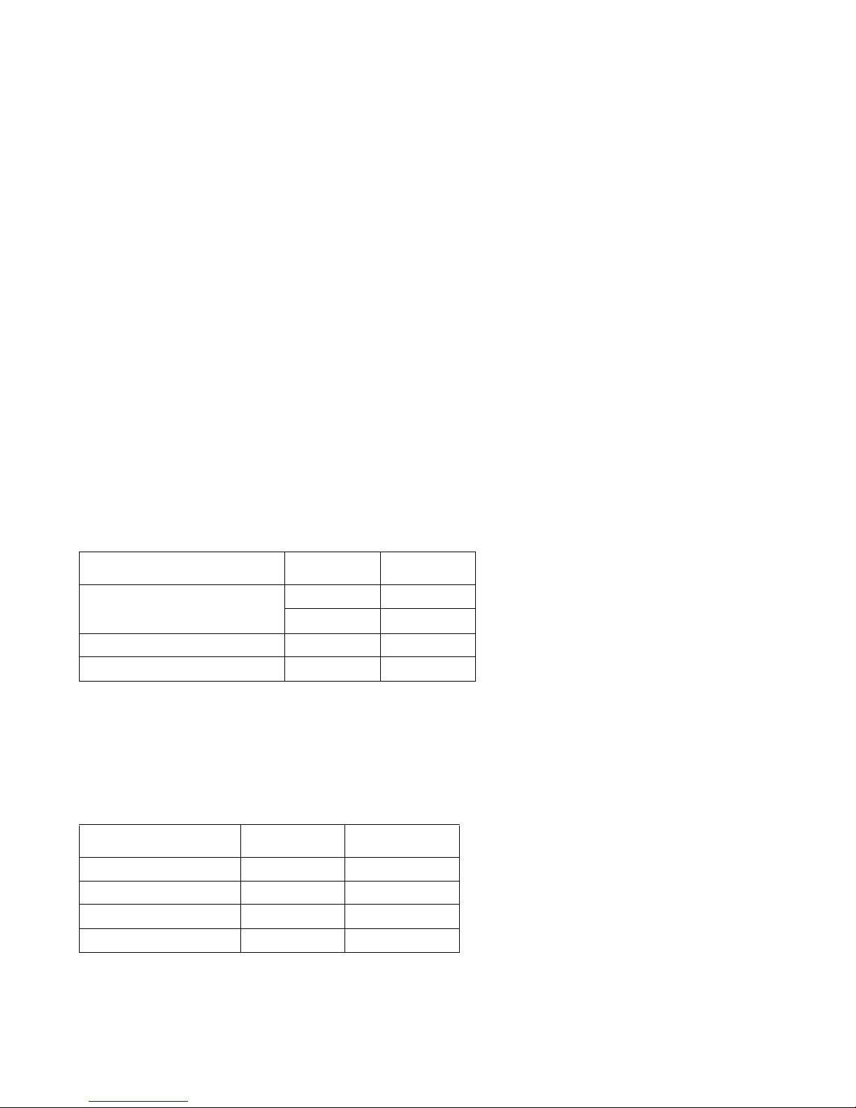
4.5.1 Command overhead
Command overhead is defined as the time required from the time the command is written into the command register by a host to the assertion of DRQ for the first data byte of a READ command when the requested data is not in
the buffer excluding Physical seek time and Latency.
The table below gives average command overhead.
Table 4: Command overhead
Command type (Drive is in quiescent state) Time (typical)
(ms)
Read (cache not hit) (from Command Write to Seek Start)
Read (cache hit) (from Command Write to DRQ)
Write (from Command Write to DRQ)
Seek (from Command Write to Seek Start)
0.5 0.5
0.1 0.2
0.015 0.2
0.5 not applicable
Time (typical) for
queued command
(ms)
4.5.2 Mechanical positioning
4.5.2.1 Average seek time (without command overhead, including settling)
Table 5: Mechanical positioning performance
Command type Typical (ms) Max (ms)
Read 8.5 9.5
Write 9.5 10.5
Read (Quiet Seek mode) 14.0 14.7
Write (Quiet Seek mode) 15.0 15.7
Deskstar T7K500 Hard Disk Drive Specification
15
The terms “Typical” and “Max” are used throughout this document and are defined as follows:
Typical The average of the drive population tested at nominal environmental and voltage conditions.
Max Maximum value measured on any one drive over the full range of the environmental and voltage
conditions. The seek time is measured from the start of the actuator’s motion to the start of a reliable read or write operation. A reliable read or write implies that error correction or recovery is not
used to correct arrival problems. The average seek time is measured as the weighted average of all
possible seek combinations.
max
Σ (m10 n)(Tnin + Tnout)
n=1
Weighted Average = ––––––––––––––––––––––––––––
(max + 1)(max)
where
max = Maximum seek length
n= Seek length (1 to max)
Tnin = Inward measured seek time for an n track seek
Tnout = Outward measured seek time for an n track seek
4.5.2.2 Full stroke seek time (without command overhead, including settling)
Table 6: Full stroke seek time
Function Typical (ms) Max (ms)
Read
Write
15.1 17.7
16.1 18.7
Read (Quiet Seek mode) 27.0 30.0
Write (Quiet Seek mode) 28.0 31.0
Full stroke seek is measured as the average of 1,000 full stroke seeks with a random head switch from both directions (inward and outward).
4.5.2.3 Single track seek time (without command overhead, including settling)
Table 7: Single track seek time
Function Typical (ms) Max (ms)
Read 0.8 1.5
Write 1.3 2.0
Read (Quiet Seek mode) 0.8 1.5
Write (Quiet Seek mode) 1.3 2.0
Single track seek is measured as the average of one (1) single track seek from every track in both directions
(inward and outward).
Deskstar T7K500 Hard Disk Drive Specification
16
 Loading...