

Page 1

|
Modo, CS33ET c,.i°s..
ModUle Tron£onneuse
Modelo CS33EA Motosierrar
I
CS33ET
(
SAFETY iNSTRUCTiONS AND iNSTRUCTiON MANUAL
;_\ WA,, RNING
iMPROPER OR UNSAFE use of this power tool can result in death or serious bodily
injury!
This manual contains important information about product safety. Please read and
understand this manual BEFORE operating the power tool. Please keep this manual
available for other users and owners before they use the power tool. This manual should
be stored in safe place.
NSTRUCTIONS DE SECURITE ET MODE D'EMPLOI
_!\ AVERTISSEMENT
Une utilJsation INCORRECTE OU DANGEREUSE de cet outil motorise peut entrainer la
mort ou de serieuses blessures corporelles!
Ce mode d'emploi contient d'importantes informations & propos de la securit6 de ce
produit. Priere de life et de comprendre ce mode d'emploi AVANT d'utiliser I'outil
motorise. Garder ce mode d'emploi & la disponibilite des autres utilisateurs et proprietaires
avant qu'ils utilisent I'outil motorise. Ce mode d'emploi dolt 6tre conserve dans un
endroit sQr.
INSTRUCCl0NESDESEGURIDADYMANUALDEINSTRUCCl0NES
:!: ADVERTENClA
iLa utilizaci6n INAPROPIADA O PEUGROSA de esta herramienta electrica puede
resultar en lesiones de gravedad o la muerte!
Este manual contiene informaci6n importante sobre la seguridad del producto. Lea y
comprenda este manual ANTES de utilizar la herramienta electrica. Guarde este manual
para que puedan leerlo otras personas antes de utilizar la herramienta electrica. Este
manual debe ser guardado en un lugar seguro.
Hitachi Koki
970-82950-200 2010.2
Page 2
English j
Meanings of symbols
NOTE! Some units do not carry them.
symboms
_WARNmNG
The following show symbols used for the machine. Be sure
4\\
\
It is important that you read, fully understand and observe the following safety precautions and
warnings. Careless or improper use of the unit may cause serious or fatal injury.
Read, understand and follow all warnings and instructions in this manual and on the unit.
that you understand their meaning before use.
@
Always wear eye, head and ear protectors when using this unit.
Warning, kickback danger. Be careful sudden and accidental upward and/or backward mo-tion
of the guide bar.
One-handed usage not permitted. While cutting, hold saw firmly with both hands with thumb
firmly locked around front handle.
Before using your machine
• Read the manual carefully.
,, Check that the cutting equipment is correctly assembled and adjusted.
,, Start the unit and check the carburetor adjustment. See "Maintenance".
Contents
What is what? ............................................................... 2
Warnings and safety instructions .................................. 3
Specifications ................................................................ 5
Assembly procedures .................................................... 6
Operating procedures ................................................... 7
Maintenance .................................................................. 11
Parts breakdown ........................................................... 45
Page 3
English
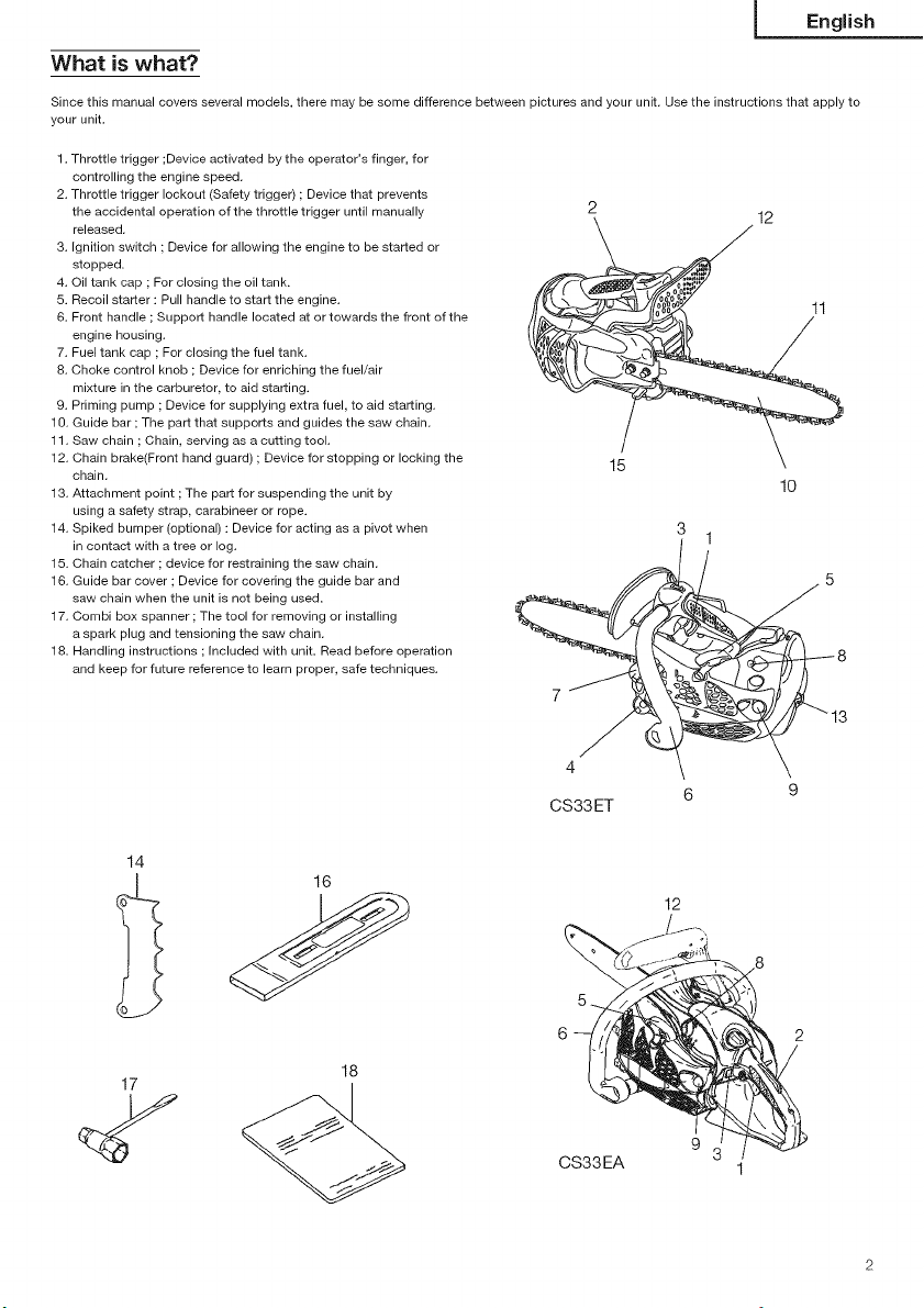
What is what?
Since this manual covers several models, there may be some difference between pictures and your unit. Use the instructions that apply to
your unit.
1. Throttle trigger ;Device activated by the operator's finger, for
controlling the engine speed.
2. Throttle trigger lockout (Safety trigger) ; Device that prevents
the accidental operation of the throttle trigger until manually
released.
3. Ignition switch ; Device for allowing the engine to be started or
stopped.
4. Oil tank cap ; For closing the oil tank.
5. Recoil starter : Pull handle to start the engine.
6. Front handle ; Support handle located at or towards the front of the
engine housing.
7. Fuel tank cap ; For closing the fuel tank.
8. Choke control knob ; Device for enriching the fuel/air
mixture in the carburetor, to aid starting.
9. Priming pump ; Device for supplying extra fuel, to aid starting.
10. Guide bar ;The part that supports and guides the saw chain.
11. Saw chain ; Chain, serving as a cutting tool.
12. Chain brake(Front hand guard) ; Device for stopping or locking the
chain.
13. Attachment point ; The part for suspending the unit by
using a safety strap, carabineer or rope.
14. Spiked bumper (optional) : Device for acting as a pivot when
in contact with a tree or log.
15. Chain catcher ; device for restraining the saw chain.
16. Guide bar cover ; Device for covering the guide bar and
saw chain when the unit is not being used.
17. Combi box spanner ; The tool for removing or installing
a spark plug and tensioning the saw chain.
18. Handling instructions ; Included with unit. Read before operation
and keep for future reference to learn proper, safe techniques.
2
12
J 11
15
10
3
1
(/ 8
7
3
4
CS33ET
6 9
14
12
17
18
9
CS33EA
Page 4
English I
Warnings and safety instructions
Operator safety
/_ WARNING!
This chain saw (CS33ET) is designed especially for tree care
and surgery. Only persons trained in tree care and surgery
may use this saw. Observe all literature, procedures and
recommendations from the relevant professional organization.
Failure to do so constitutes a high accident risk. We
recommend always using a rising platform for sawing in trees.
Rappelling techniques are extremely dangerous and require
special training. The operator must be trained in and familiar
with the use of safety equipment and working and climbing
techniques. Always use the restraining equipment for both the
operator and the saw.
Always wear a safety face shield or goggles.
Always use the gloves to reduce the effects of vibration.
Gloves should be used when sharpening chain.
Always wear safety protective equipment such as jacket,
trousers, gloves, helmet, boots with steel toe-caps and non-slip
soles whenever you use a chain saw. For working in trees the
safety boots must be suitable for climbing techniques. Do not
wear loose clothing, jewelry, short pants, sandals or go barefoot.
Secure hair so it is above shoulder length.
Do not operate this tool when you are tired, ill or under the
influence of alcohol, drugs or medication.
Never let a child or inexperienced person operate the machine.
Wear hearing protection. Pay attention to your surroundings.
Be aware of any bystanders who may be signaling a problem.
Remove safety equipment immediately upon shutting off engine.
Wear head protection.
Never start or run the engine inside a closed room or building.
Breathing exhaust fumes can kill.
For respiratory protection, wear a protection mask while emitting
the chain oil mist and dust from sawdust.
Keep handles free ofoil and fuel.
Keep hands away from cutting equipment.
Do not grab or hold the unit by the cutting equipment.
When the unit is turned off, make sure the cutting attachment has
stopped before the unit is set down.
When operation is prolonged, take a break from time to time so
that you may avoid possible whitefinger disease which is caused
by vibration.
The operator must obey the local regulations of cutting area.
_ WARNING!
Antivibration systems do not guarantee that you will not
sustain whitefinger disease or carpal tunnel syndrome.
Therefore, continual and regular users should monitor closely
the condition of their hands and fingers, if any of the above
symptoms appear, seek medical advice immediately.
/!_ WARNING!
Long or continuous exposure to high noise levels may cause
permanent hearing impairment. Always wear approved hearing
protection when operating a unit/machine.
/_ WARNING !
if you are using any medical electric/electronic devices such
as a pacemaker, consult your physician as well as the device
manufacturer prior to operating any power equipment.
Unit / machine safety
Inspect the entire unit/machine before each use. Replace
damaged parts. Check for fuel leaks and make sure all fasteners
are in place and securely tightened.
Replace parts that are cracked, chipped or damaged in any way
before using the unit/machine.
Make sure the side case is properly attached.
Keep others away when making carburetor adjustments.
Use only accessories as recommended for this unit/machine by
the manufacturer.
Never let the chain strike any obstacle. Ifthe chain makes
contact, the machine should be stopped and checked carefully.
Make sure the automatic oiler is working.Keep the oil tank filled
with clean oil. Never let chain run dry on the bar.
All chainsaw service, other than the items listed in the operator's/
owner's manual, should be performed by competent chain-saw
service personnel. (For example, if improper tools are used to
remove the flywheel or if an improper tool is used to hold the
flywheel in order to remove the clutch, structural damage to the
flywheel could occur and could subsequently cause the flywheel
to burst.)
_\ WARNING!
Never modify the unit/machine in any way. Do not use your
unit/machine for any job except that for which it is intended.
_ WARNING!
Never use chain saw without any safety equipment or that
has faulty safety equipment, it could result in serious personal
injury.
WARNING!
Using guide bar/chain other than recommended by the
manufacturer which are not approved, could result in a high
risk of personal accidents or injury.
Fuel safety
Mix and pour fuel outdoors and where there are no sparks or
flames.
Use a container approved for fuel.
Do not smoke or allow smoking near fuel or the unit/machine or
while using the unit/machine.
Wipe up all fuel spills before starting engine.
Move at least 10ft (3m) away from fueling site before starting
engine.
Stop engine before removing fuel cap.
Empty the fuel tank before storing the unit/machine. It is
recommended that the fuel be emptied after each use. If fuel is
left in the tank, store so fuel will not leak.
Store unit/machine and fuel in area where fuel vapors cannot
reach sparks or open flames from water heaters, electric motors
or switches, furnaces, etc.
_\ WARNING ]
Fuel is easy to ignite or get explosion or inhale fumes, so that
pay special attention when handling or filling fuel
Page 5
Cuttingsafety
Donotcutanymaterialotherthanwoodorwoodenobjects.
Forrespiratoryprotection,wearanaerosolprotectionmaskwhen
cuttingthewoodafterinsecticidehasbeenapplied.
Keepothersincludingchildren,animals,bystandersandhelpers
outsidethehazardzone,Stoptheengineimmediatelyifyouare
approached.
Holdtheunit/machinefirmlywiththerighthandontherear
handleandthelefthandonthefronthandle.
Keepfirmfootingandbalance.Donotover-reach.
Keepallpartsofyourbodyawayfromthemufflerandcutting
attachmentwhentheengineisrunning.
KeepBar/Chainbelowwaistlevel.
Beforefellingatree,theoperatormustbeaccustomedtothe
sawingtechniquesofthechainsaw.
Besuretopre-planasafeexitfromafailingtree.
Whilecutting,holdsawfirmlywithbothhandswiththumbfirmly
lockedaroundfronthandle,andstandwithfeetwellbalanced
andyourbodybalanced.
Standtothesideofthesawwhencuttingneverdirectlybehindit.
Alwayskeepthespikedbumperfacetoatree,becausethechain
maysuddenlybedrawnintoatree.
Whencompletingacut,bereadytoholduptheunitsasitbreaks
intoclear,soitwillnotfollowthroughandcutyourlegs,feetor
body,orcontactanobstruction.
Bealertagainstkickback(whensawkicksupandbackat
operator).Nevercutwiththenoseofthebar.
Whenrelocatingtoanewworkarea,besuretoshutoffthe
machineandensurethatallcuttingattachmentsarestopped.
Neverplacethemachineonthegroundwhenrunning.
Alwaysensurethattheengineisshutoffandanycutting
attachmentshavecompletelystoppedbeforeclearingdebrisor
removinggrassfromthecuttingattachment.
Alwayscarryafirst-aidkitwhenoperatinganypowerequipment.
Neverstartorruntheengineinsideaclosedroomorbuilding
and/orneartheinflammableliquid.Breathingexhaustfumescan
kill.
I English
Transport and storage
* Carry the uniVmachine by hand with the engine stepped and the
muffler away from your body.
Allow the engine to cool, empty the fuel tank, and secure the unit/
machine before storing or transporting in avehicle.
Empty the fuel tank before storing the unit/machine, it is
recommended that the fuel be emptied after each use. If fuel is
left in the tank, store so fuel will not leak.
Store unit/machine out of the reach of children.
Clean and maintenance the unit carefully and store it in a dry
place.
Make sure engine switch is off when transporting or storing.
When transporting in a vehicle or storage, cover chain with chain
cover.
if situations occur which are not covered in this manual, take care
and use common sense. Contact HiTACHi dealer if you need
assistance. Pay special attention to statements preceded by the
following words:
/1\ WARNING!
indicates a strong possibility of severe personal injury or loss
of life, if instructions are not followed,
CAUTION!
Indicates a possibility of personal injury or equipment damage, if
instructions are not followed.
NOTE!
Helpful information for correct function and use.
Maintenance safety
Maintain the unit/machine according to recommended
procedures.
Disconnect the spark plug before performing maintenance except
for carburetor adjustments.
Keep others away when making carburetor adjustments.
Use only genuine HITACHI replacement parts as recommended
by the manufacturer.
CAUTION!
Do not disassemble the recoil starter on. You may get a possibility
of personal injury with recoil spring.
WARNING!
improper maintenance could result in serious engine damage
or in serious personal injury,
Page 6
English j
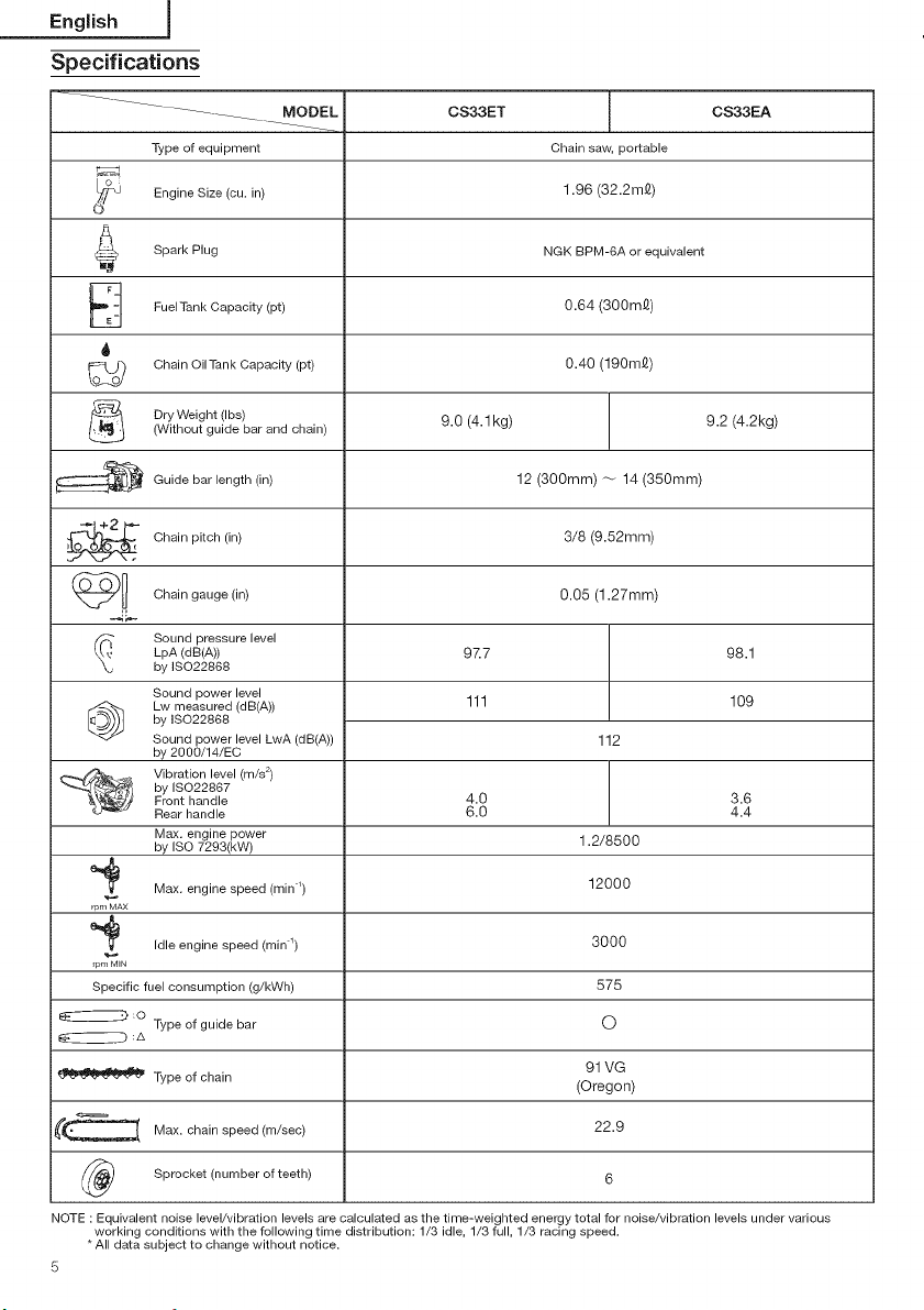
Specifications
...........................
"i_jpe of equipment Chain saw, portable
MODEL CS33ET CS33EA
Engine Size (cu. in) 1.96 (32.2mQ)
Spark Plug NGK BPM-6A or equivalent
FuelTank Capacity (pt) (300m_)
oo_o Chain Oil Tank Capacity (pt) 0.40 (190mQ)
Dry Weight (Ibs) 9.0 9.2
(Without guide bar and chain)
_ Guide bar length (in) 12 (30Omm) _ 14 (350mm)
Chain pitch (in) 3/8 (9.52mm)
Chain gauge (in) 0.05 (1.27mm)
Sound pressure level
LpA (dB(A)) 97.7 98.1
by ISO22868
Sound power level
Lw measured (dB(A))
by ISO22868
@
Sound power level LwA (dB(A))
by 2000/14/EC
Vibration level (m/s 2)
by ISO22867
Front handle
Rear handle
Max. engine power
by ISO 7293(kW)
e_ Max. engine speed (min _) 12000
rpr_AX
e_ Idle engine speed (min _) 3000
rpr_lN
Specific fuel consumption (g/kWh) 575
@:o
Type of guide bar O
(4.1 kg) (4.2kg)
111 109
4.0 3.6
6.0 4.4
0.64
112
1.2/8500
Type of chain (Oregon)
_ Max. chain speed (m/sec)
(_ Sprocket (number of teeth)
NOTE : Equivalent noise level/vibration levels are calculated as the time-weighted energy total for noise/vibration levels under various
working conditions with the following time distribution: 1/3 idle, 1/3 full, 1/3 racing speed.
* All data subject to change without notice.
5
91 VG
22.9
6
Page 7

Assembly procedures
/i\ WARNING!
Never try to start engine without side case securely fastened.
1. Remove chain bar clamp nuts (1).
2. Remove the side case (2) as pinching the rear part of the side
case (2) ,(Fig. 1)
00
D
English
5. Guide the chain drive links into the bar groove all around the bar.
6. Install the side case (2) onto the guide bar clamp bolts on the
engine case.
Then fix the clamp nuts temporarily. (Fig. 1)
7. Raise the bar end, and tighten the chain (10) by turning the
tension adjustment bolt (11) clockwise. To check proper tension,
lightly lift up the center of chain and there should be about
O.O2~O.O4in (O.5.-1.Omm) clearance between bar and edge of
drive link (12). (Fig. 5, 6)
Fig. 1
* In case of installing the spiked bumper (3), remove the guide
plate A (4) first and install the spiked bumper (3) (if so equipped)
to the unit with two screws, and then install the guide plate A (4)
in place. (Fig.2)
Fig. 2
3. install, the chain bar (5) onto the bolts (6), then push it toward
the sprocket (7) as far as it will go. Make sure that the boss of
chain tension adjust bolt (8) fits into the hole of the bar (9). (Fig. 3)
NOTE!
Slightly move the bar back and forth and make sure the chain
tension boss (8) fits into the hole (9) in the bar properly. (Fig. 3)
4. Confirm the direction of saw chain (10) is correct as in the figure,
and align the chain on the sprocket. (Fig. 4)
7 5
9 6
Fig. 3
11 10
ram)
Fig. 5
Fig. 6
CAUTION!
PROPERTENSION IS EXTREMELY IMPORTANT!
8. Raise the bar end and securely tighten the chain bar clamp nuts
with the combi box spanner. (Fig. g)
9. A new chain will stretch so adjust the chain after a few cuts and
watch chain tension carefully for the first half hour of cutting.
NOTE!
Check the chain tension frequently for optimum performance and
durability.
CAUTION!
When the chain is excessively tightened, the bar and chain will
be damaged rapidly. Conversely, when the chain is excessively
loosened, it may get out of the groove inthe bar.
Always wear gloves when touching the chain.
Fig. 4
/_ WARNING!
During operation, hold chain saw firmly with both hands, A
single hand operation may cause serious injury.
Page 8

English j
Operating procedures
Fuel (Fig. 7)
A_B
Fig. 7
/_\ WARNING!
= The chain saw is equipped with a two-stroke engine. Always
run the engine on fuel, which is mixed with oil. Provide good
ventilation, when fueling or handling fuel
* Fuel contains highly flammable and it is possible to get the
serious personal injury when inhaling or spilling on your body.
Always pay attention when handling fuel. Always have good
ventilation when handling fuel inside building.
Fuel
* Always use branded 89 octane unleaded gasoline.
* Use genuine two-cycle oil or use a mix between 25:1 to 50:1,
please consult the oil bottle for the ratio or HITACHI dealer.
Only for the state of California at 50:1.
If genuine oil is not available, use an anti-oxidant added quality
oil expressly labeled for air-cooled 2-cycle engine use(JASO FC
GRADE OiL or ISO EGC GRADE). Do not use BIA orTCW (2-stroke
water-cooling type) mixed oil.
Never use multi-grade oil (10 W/30) or waste oil.
Always mix fuel and oil in a separate clean container.
Always start by filling half the amount of fuel, which is to be used.
Then add the whole amount of oil. Mix (shake) the fuel mixture. Add
the remaining amount of fuel.
Mix (shake) the fuel-mix thoroughly before filling the fuel tank.
Fueling
J!\_WARNING! (Fig. 8)
= Always shut off the engine before refueling.
* Slowly open the fuel tank (13), when filling up with fuel, so
that possible overpressure disappears.
* Tighten the fuel cap carefully, after fueling.
* Always move the unit at least 10ft (3m) from the fueling area
before starting.
* Always Wash any spilled fuel from clothing immediately with
soap.
= Be sure to check any fuel leaking after refueling.
13 1478_-_
NOTE!
When pouring fuel (13) or chain oil (14) into the tank, place the unit
with cap side up. (Fig. 8)
ADJUSTMENT OF CHAIN OIL SUPPLY
The chain oil quantity discharged through the lubrication system is
factory adjusted to the maximum. Adjust the quantity in accordance
with the operating condition.
Turn the adjusting screw (15) counter-clockwise to increase the
quantity and turn it clockwise to decrease the quantity. (Fig. 9)
(standard setting turns counter-clockwise 1-1 1/2 from slightly
seated)
15
®
Fig. 9
Starting (Fig. 10, 11)
/_._WARNING]
When the engine starts with the throttle lock engaged, the
engine speed is high enough to make the chain rotate.
CAUTION!
Before starting, make sure the chain brake is engaged (if so
equipped) and that the bar/chain does not touch anything.
1. Set ignition switch (16) to ON position.
*Push priming bulb (18) several times so that fuel flows through
bulb into carburetor. (If so equipped) (Fig. 10)
ON 17
_- _18
Fig. 10
2. Push the choke lever (17) down to choked position. This will
automatically lock the throttle in starting position. (Fig. 10)
3. Pull recoil starter briskly, taking care to keep the handle in your
grasp and not allowing it to snap back. (Fig. 10)
4. When you hear the engine want to start, with the safety trigger (19)
pressed pull throttle trigger (20). This will release the throttle from
starting position to ran position and will automatically return the
choke lever to run position. (Fig.10, 11)
Fig. 8
Before fueling, clean the tank cap area carefully, to ensure that
no dirt falls into the tank. Make sure that the fuel is well mixed by
shaking the container, before fueling.
Chain oil (Fig. 8)
Fill up with chain oil (14). Always use good quality chain oil. When
the engine is running, the chain oil is automatically discharged.
20 1_
Fig. 11
Page 9
5.Pullrecoilstarterbrisklyagainintheaforementionedmanner.
(Fig.12)
Afterenginestarts,makesurethechainbrakeisdisengaged.
English
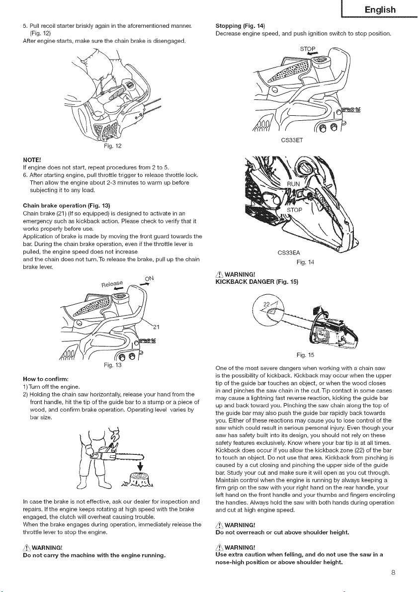
Stopping (Fig. 14)
Decrease engine speed, and push ignition switch to stop position.
STO_)_
Fig.12
NOTE!
ifenginedoesnotstart,repeatproceduresfrom2to5.
6.Afterstartingengine,pullthrottletriggertoreleasethrottlelock.
Thenallowtheengineabout2-3minutestowarmupbefore
subjectingittoanyload.
Chain brake operation (Fig, 13)
Chain brake (21) (If so equipped) is designed to activate in an
emergency such as kickback action. Please check to verify that it
works properly before use.
Application of brake is made by moving the front guard towards the
bar. During the chain brake operation, even if the throttle lever is
pulled, the engine speed does not increase
and the chain does not turn. To release the brake, pull up the chain
brake lever.
Re\e_,_
Fig. 13
How to confirm:
1)Turn off the engine.
2) Holding the chain saw horizontally, release your hand from the
front handle, hit the tip of the guide bar to a stump or a piece of
wood, and confirm brake operation. Operating level varies by
bar size.
in case the brake is not effective, ask our dealer for inspection and
repairs, if the engine keeps rotating at high speed with the brake
engaged, the clutch will overheat causing trouble.
When the brake engages during operation, immediately release the
throttle lever to stop the engine.
_.\ WARNING!
Do not carry the machine with the engine running,
O_q
CS33ET
7,
CS33EA
Fig. 14
_ WARNING!
KICKBACK DANGER (Fig, 15)
Fig. 15
One of the most severe dangers when working with a chain saw
is the possibility of kickback. Kickback may occur when the upper
tip of the guide bar touches an object, or when the wood closes
in and pinches the saw chain in the cut.Tip contact in some cases
may cause a lightning fast reverse reaction, kicking the guide bar
up and back toward you. Pinching the saw chain along the top of
the guide bar may also push the guide bar rapidly back towards
you. Either of these reactions may cause you to lose control of the
saw which could result in serious personal injury. Even though your
saw has safety built into its design, you should not rely on these
safety features exclusively. Know where your bar tip is at all times.
Kickback does occur if you allow the kickback zone (22) of the bar
totouch an object. Do not use that area. Kickback from pinching is
caused by a cut closing and pinching the upper side of the guide
bar. Study your cut and make sure it will open as you cut through.
Maintain control when the engine is running by always keeping a
firm grip on the saw with your right hand on the rear handle, your
left hand on the front handle and your thumbs and fingers encircling
the handles. Always hold the saw with both hands during operation
and cut at high engine speed.
/t\ WARNING!
Do not overreach or cut above shoulder height,
/!_ WARNING!
Use extra caution when felling, and do not use the saw in a
nose-high position or above shoulder height,
Page 10
English j
CHAIN CATCHER
The chain catcher is located on the power head just below the
chain to further prevent the possibility of a broken chain striking the
chainsaw user.
/._, WARNING!
Do not stand in-line with chain when cutting.
BASICTECHNIQUES FOR MAKING FELLING, MMBING AND
BUCKING CUTS
The intention of the following information is to provide you with the
general introduction to wood cutting techniques.
/_\ WARNING!
This information does not cover all specific situations, which
may depend on differences in terrain, vegetation, kind of wood,
form and size of trees, etc. Consult your servicing dealer,
forestry agent or local forestry schools for advice on
specific woodeutting problems in your area,This will make your
work more efficient and safer.
/I._ WARNING!
Avoid cutting Jn adverse weather conditions, such as dense
fog, heavy rain, bitter cold, high winds, etc.
Adverse weather is often tiring to work Jn and creates
potentially dangerous conditions such as slippery ground.
High winds may force the tree to fall in an unexpected direction
causing property damage or personal injury.
CAUTION!
Never use a chainsaw to pry or for any purpose for which it is not
intended.
/g._WARNING!
Avoid stumbling on obstacles such as stumps, roots, rocks,
branches and fallen trees. Watch out for holes and ditches. Be
extremely cautious when working on slopes or uneven ground.
Shut off the saw when moving from one work place to another.
Always cut at wide open throttle. A slow moving chain can
easily catch and force the saw to jerk.
Never use the saw with only one hand.
You cannot control the saw properly and you may lose control
and injure yourself severely.
Keep the saw body close to your body to improve control and
reduce strain.
When cutting with the bottom part of the chain the reactive
force will pull the saw away from you towards the wood you
are cutting.
The saw will control the feeding speed and sawdust will be
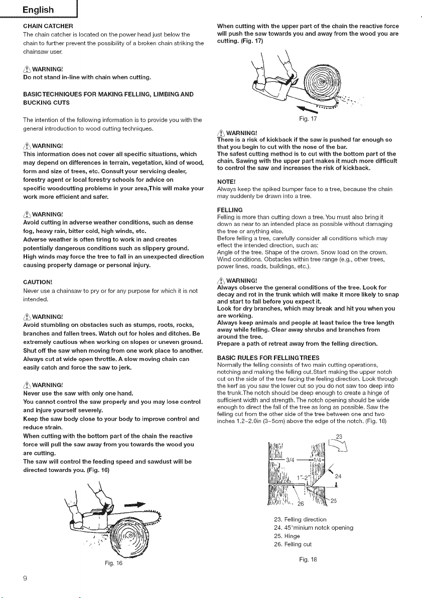
directed towards you. (Fig. 16)
When cutting with the upper part of the chain the reactive force
will push the saw towards you and away from the wood you are
cutting. (Fig. 17)
Fig. 17
/t\ WARNING!
There is a risk of kickback if the saw is pushed far enough so
that you begin to cut with the nose of the bar.
The safest cutting method is to cut with the bottom part of the
chain. Sawing with the upper part makes it much more difficult
to control the saw and increases the risk of kickback.
NOTE!
Always keep the spiked bumper face to a tree, because the chain
may suddenly be drawn into a tree.
FELLING
Felling is more than cutting down atree.You must also bring it
down as near to an intended place as possible without damaging
the tree or anything else.
Before felling a tree, carefully consider all conditions which may
effect the intended direction, such as:
Angle of the tree. Shape of the crown. Snow load on the crown.
Wind conditions. Obstacles within tree range (e.g., other trees,
power lines, roads, buildings, etc.).
/!\WARNING!
Always observe the general conditions of the tree. Look for
decay and rot in the trunk which will make it more likely to snap
and start to fall before you expect it.
Look for dry branches, which may break and hit you when you
are working,
Always keep animals and people at least twice the tree length
away while felEng, Clear away shrubs and branches from
around the tree.
Prepare a path of retreat away from the felling direction.
BASIC RULES FOR FELMNGTREES
Normally the felling consists of two main cutting operations,
notching and making the felling cut.Start making the upper notch
cut on the side of the tree facing the feeling direction. Look through
the kerf as you saw the lower cut so you do not saw too deep into
the trunk.The notch should be deep enough to create a hinge of
sufficient width and strength. The notch opening should be wide
enough to direct the fall of the tree as long as possible. Saw the
felling cut from the other side of the tree between one and two
inches 1.2~2.0in (3._5cm) above the edge of the notch. (Fig. 18)
23
Fig. 16
23. Felling direction
24.45°minium notck opening
25. Hinge
26. Felling cut
Fig. 18
Page 11
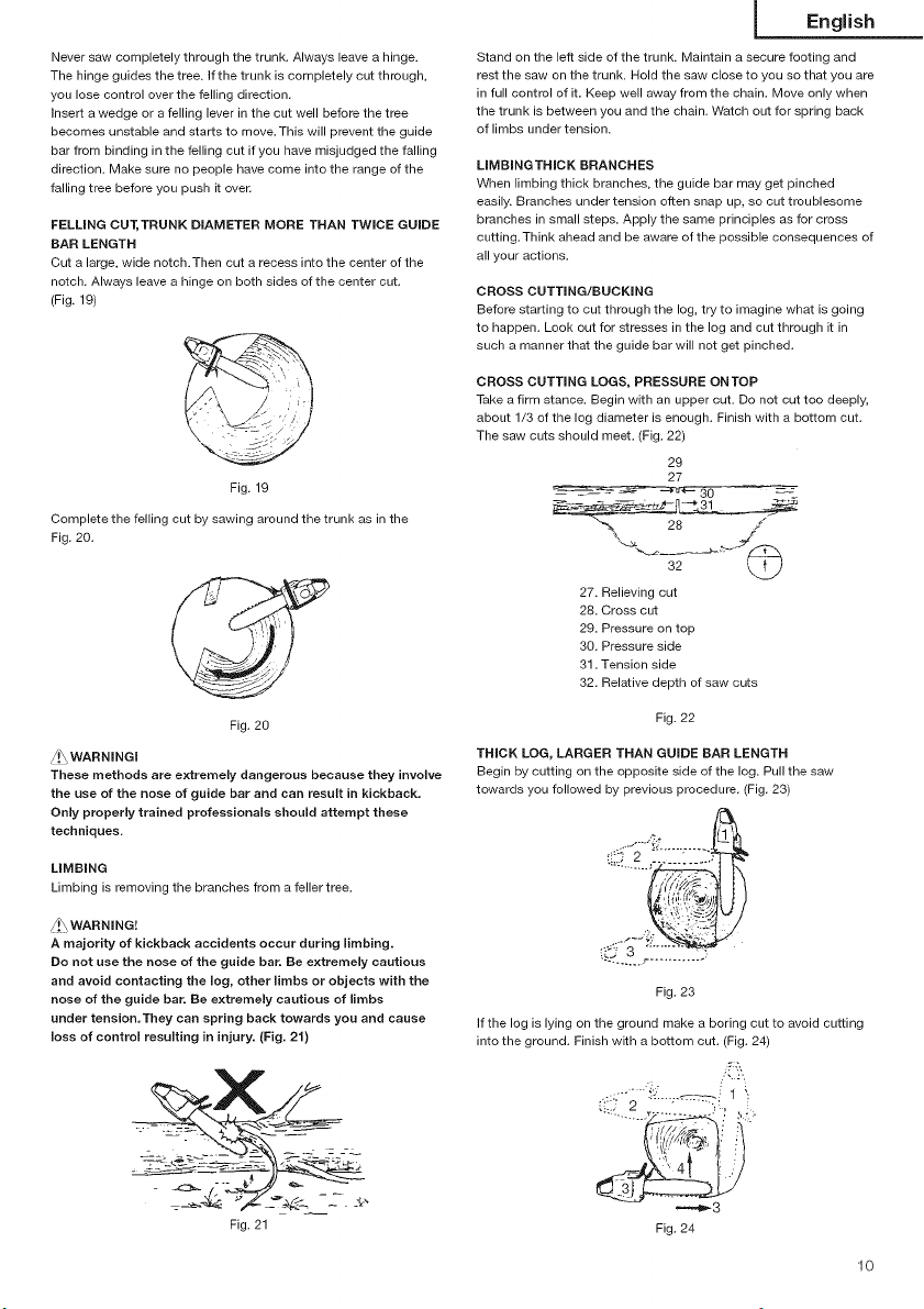
Neversawcompletelythroughthetrunk.Alwaysleaveahinge.
Thehingeguidesthetree.ifthetrunkiscompletelycutthrough,
youlosecontroloverthefellingdirection.
insertawedgeorafellingleverinthecutwellbeforethetree
becomesunstableandstartstomove.Thiswillpreventtheguide
barfrombindinginthefellingcutifyouhavemisjudgedthefalling
direction.Makesurenopeoplehavecomeintotherangeofthe
fallingtreebeforeyoupushitover.
FELLING CUT, TRUNK DIAMETER MORE THAN TWICE GUIDE
BAR LENGTH
Cut a large, wide notch.Then cut a recess into the center of the
notch. Always leave a hinge on both sides of the center cut.
(Fig. 19)
Fig. 19
Complete the felling cut by sawing around the trunk as in the
Fig. 20.
Fig. 20
/!\ WARNINGI
These methods are extremely dangerous because they involve
the use of the nose of guide bar and can result in kickback.
Only properly trained professionals should attempt these
techniques.
LIMBING
Limbing is removing the branches from a feller tree.
A\WARNING!
A majority of kickback accidents occur during iimbing.
Do not use the nose of the guide bar. Be extremely cautious
and avoid contacting the log, other limbs or objects with the
nose of the guide bar. Be extremely cautious of limbs
under tension,They can spring back towards you and cause
loss of control resulting in injury. (Fig. 21)
English
Stand on the left side of the trunk. Maintain a secure footing and
rest the saw on the trunk. Hold the saw close to you so that you are
in full control of it. Keep well away from the chain. Move only when
the trunk is between you and the chain. Watch out for spring back
of limbs under tension.
LIMBINGTHICK BRANCHES
When limbing thick branches, the guide bar may get pinched
easily. Branches under tension often snap up, so cut troublesome
branches in small steps. Apply the same principles as for cross
cutting.Think ahead and be aware of the possible consequences of
all your actions.
CROSS CUTTING/BUCKING
Before starting to cut through the log, try to imagine what is going
to happen. Look out for stresses in the log and cut through it in
such a manner that the guide bar will not get pinched.
CROSS CUTTING LOGS, PRESSURE ONTOP
Take a firm stance. Begin with an upper cut. Do not cut too deeply,
about 1/3 of the log diameter is enough. Finish with a bottom cut.
The saw cuts should meet. (Fig. 22)
29
27
32 LLJ
27. Relieving cut
28. Cross cut
29. Pressure on top
30. Pressure side
31. Tension side
32. Relative depth of saw cuts
Fig. 22
THICK LOG, LARGER THAN GUIDE BAR LENGTH
Begin by cutting on the opposite side of the log. Pull the saw
towards you followed by previous procedure. (Fig. 23)
Fig. 23
if the log is lying on the ground make a boring cut to avoid cutting
into the ground. Finish with a bottom cut. (Fig. 24)
/:-,,
:,. :,.
(:i:.:/-2 :_":'_J 1 _
Fig. 21
=='=_3
Fig. 24
1o
Page 12
English j
/!\WARNING! KICKBACK DANGER!!
Do not attempt a boring cut ifyou are not properly trained. A
boring cut involves the use of the nose of the guide bar and
can result in kickback.
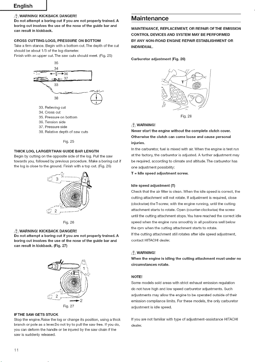
CROSS CUTTING LOGS, PRESSURE ON BOTTOM
Take a firm stance. Begin with a bottom cut.The depth of the cut
should be about 1/3 of the log diameter.
Finish with an upper cut. The saw cuts should meet. (Fig. 25)
35
34
"_._ 33
33. Relieving cut
34. Cross cut
35. Pressure on bottom
36. Tension side
37. Pressure side
38. Relative depth of saw outs
Fig. 25
THICK LOG, LARGERTHAN GUIDE BAR LENGTH
Begin by cutting on the opposite side of the log. Pull the saw
towards you, followed by previous procedure. Make a boring cut if
the log is close to the ground. Finish with a top cut. (Fig. 26)
Maintenance
MAINTENANCE, REPLACEMENT, OR REPAIR OFTHE EMISSION
CONTROL DEVmCESAND SYSTEM MAY BE PERFORMED
BY ANY NON-ROAD ENGINE REPAIR ESTABLISHMENT OR
iNDiViDUAL.
Carburetor adjustment (Fig. 28)
Fig. 28
/!\_ WARNING!
Never start the engine without the complete clutch cover.
Otherwise the clutch can come loose and cause personal
injuries.
in the carburetor, fuel is mixed with air. When the engine is test run
at the factory, the carburetor is adjusted. A further adjustment may
be required, according to climate and altitude.The carburetor has
one adjustment possibility:
T = Idle speed adjustment screw.
Fig. 26
/_!_WARNING! KICKBACK DANGER!!
Do not attempt a boring cut if you are not properly trained. A
boring cut involves the use of the nose of the guide bar and
can result in kickback. (Fig. 27)
Fig. 27
IFTHE SAW GETS STUCK
Stop the engine.Raise the log or change its position, using a thick
branch or pole as a lever.Do not try to pull the saw free. If you do,
you can deform the handle or be injured by the saw chain if the
saw is suddenly released.
11
Idle speed adjustment (T)
Check that the air filter is clean. When the idle speed is correct, the
cutting attachment will not rotate, if adjustment is required, close
(clockwise) theT-screw, with the engine running, until the cutting
attachment starts to rotate. Open (counter-clockwise) the screw
until the cutting attachment stops. You have reached the correct idle
speed when the engine runs smoothly in all positions well below
the rpm when the cutting attachment starts to rotate.
if the cutting attachment still rotates after idle speed adjustment,
contact HiTACHi dealer.
/!\_ WARNING!
When the engine is idling the cutting attachment must under no
circumstances rotate.
NOTE!
Some models sold areas with strict exhaust emission regulation
do not have high and low speed carburetor adjustments. Such
adjustments may allow the engine to be operated outside of their
emission compliance limits. For these models, the only carburetor
adjustment is idle speed.
if you are not familiar with type of adjustment-assistance HITACHI
dealer.
Page 13

Air filter (Fig, 29)
The air filter (40), (43) and cleaner sponge (41), (42) must be cleaned
from dust and dirt in order to avoid:
Carburetor malfunctions.
Starting problems.
Engine power reduction.
Unnecessary wear on the engine parts.
Abnormal fuel consumption.
Clean the air filter daily or more often if working in exceptionally
dusty areas.
(For CS33ET)
Remove the air filter cover (39), air filter (40) and the cleaner sponge
(41), (42).
NOTE!
When removing the air filter (40) from the unit, turn the air filter
1/8th counter-clockwise (CS33ET)
(For CS33EA)
Remove the air filter cover (39) and pull the tab (46) on the air filter
(43).
NOTE!
When installing the air filter (43) on the unit, please take the
following steps:
1.Set the hole (45) on the air filter to the boss (46) first.
2. Fit the installing hole (47) on the air filter on the part (48) on the
rear handle. Push the air filter down till you hear the click.
Cleaning the air filter
Remove the air filter cover (39) and the filter (40), (43).
I
English
Spark plug (Fig. 30)
The spark plug condition is influenced by:
An incorrect carburetor setting.
Wrong fuel mixture (too much oil in the gasoline)
A dirty air filter.
Hard running conditions (such as cold weather).
These factors cause deposits on the spark
plug electrodes, which may result in malfunction and starting
difficulties. If the engine is low on power, difficult to start or runs
poorly at idling speed, always check the spark plug first. If the
spark plug is dirty, clean it and check the electrode gap. Readjust
if necessary. The correct gap is 0.024" (0.6 mm).The spark plug
should be replaced after about 100 operation hours or earlier if the
electrodes are badly eroded.
Fig. 30
NOTE!
In some areas, local law requires using a resistor spark plug to
suppress ignition signals. If this machine was originally equipped
with resistor spark plug, use same type of spark plug for
replacement.
Oiler port (Fig, 31)
Clean the chain oiler port (49) whenever possible.
O 41 39
CS33EA
NOTE!
When removing the filter from the unit, turn the filter 1/8 turn to
counter-clockwise.
Rinse them in warm soap suds. Check that the filter is dry before
reassembly, An air filter that has been used for some time cannot
be cleaned completely,Therefore, it must regularly be replaced with
a new one. A damaged filter must always be replaced.
48
Fig. 29
49
/
Fig. 31
Guide bar (Fig. 32)
Before using the machine, clean the groove and oiler port (50) in
the bar with the special gauge offered as an optional accessory.
5O
Fig. 32
12
Page 14

English j
Side case {Fig. 33)
Always keep the side case and drive area clean of saw dust and
debris.Periodically apply oil or grease to this area to protect from
corrosion as some trees contain high levels of acid.
CHAIN SHARPEMNG Parts of a cutter. (Fig. 36, 37)
/_._WARNING!
Gloves should be used when sharpening chain.
/!\ WARNING!
Be sure to round off the front edge to reduce the chance of
kickback or tie-strap breakage.
52 51
54
Fig. 33
Fuel filter (Fig. 34)
Remove the fuel filter from the fuel tank and thoroughly wash it in
solvent. After that, push the filter into the tank completely.
Fig. 34
NOTE!
If the filter is hard due to dust and dirt, replace it.
Chain oil filter (Fig. 35)
Remove the oil filter and thoroughly wash it in solvent.
I
Fig. 35
For long-term storage
Drain all fuel from the fuel tank. Start and let engine run until it
stops. Repair any damage which has resulted from use. Clean the
unit with a clean rag, orthe use of high pressure air hose. Put a few
drops of two-cycle engine oil into the cylinder through the spark
plug hole, and spin the engine over several times to distribute oil.
Cover the unit and store it in a dry area.
59
51. Top plate
52. Working corner
53. Side plate
54. Gullet
55. Heel
56. Chassis
57_ Rivet hole
58. Toe
59. Depth gauge
Fig. 36
60 61
63
60. Correct angle on top plate (degree of angle depends on chain type)
61. Slightly protruding "hook" or point (curve on non-chisel chain)
62. Top of depth gauge at correct height below top plate
63. Front of depth gauge rounded off
Fig. 37
LOWERING DEPTH GAUGES WiTH A FILE
1) If you sharpen your cutters with a file holder, check and lower the
depth.
2) Check depth gauges every third sharpening.
3) Place depth gauge tool on cutter. If depth gauge projects, file it
level with the top of the tool. Always file from the inside of the
chain toward an outside cutter. (Fig. 38)
Fig. 38
13
Page 15

4) Round off front corner to maintain original shape of depth gauge
after using depth gauge tool. Always follow the recommended
depth gauge setting found in the maintenance or operator
manual for your saw. (Fig. 39)
Fig. 39
GENERAL INSTRUCTIONS FOR FILING CUTTERS
File (64) cutter on one side of the chain from the inside out.
File on forward stroke only. (Fig. 40)
Fig. 40
5) Keep all cutters the same length. (Fig. 41)
I _ I__ I
Fig. 41
6) File enough to remove any damage to cutting edges (side plate
(65) and top plate (66)) of cutter. (Fig. 42)
English
Daily maintenance
* Clean the exterior of the unit.
Clean the chain oil filter port.
Clean the groove and oil filter port in the guide bar.
Clean the side case of saw dust.
Check that the saw chain is sharp.
Check that the bar nuts are sufficiently tightened.
Make sure that the chain transport guard is undamaged and that
it can be securely fitted.
Check that nuts and screws are sufficiently tightened.
Weekly maintenance
Check the starter, especially cord.
Clean the exterior of the spark plug.
Remove the spark plug and check the electrode gap. Adjust it
to 0.024" (0.6mm) or change the spark plug.
Check that the air intake at the starter is not clogged.
Clean the air filter.
Monthly maintenance
Rinse the fuel tank with gasoline, and clean fuel filter.
Clean chain oil filter.
Clean the exterior of the carburetor and the space around it.
Quarterly maintenance
Clean the cooling fins on the cylinder.
Clean the fan and the space around it.
Clean the muffler of carbon,
CAUTION
Cleaning of cylinder fins, fan and muffler shall be done by a
HITACHI Authorized Service Center.
MODEL NO. BAR NO. LENGTH- CHAIN NO.
OREGON TYPE
CS33ET/ 120SDEA041 12"-DG 91VG-045X
CS33EA 140SDEA041 14"-DG g1VG-052X
DG-DOUBLE GUARD TM (is registered trademark of BLOUNT
International) ... Reversible reduced kickback-bar.
65 66
Fig. 42
SHARPENING ANGLES FOR SHARPENING SAW CHAIN
1. Part Number 91VG
2. Pitch 3/8"
3. Deth Gauge Settig 0.025"
4. Side Plate Filing Angle 80 °
5. Top Plate Angle 30 °
_ 6. File Guide Angle 90 °
Maintenance schedule
Below you will find some general maintenance instructions. For
further information please contact HITACHI dealer.
14
Page 16
Francois 1
Signification des symboles
REMARQUE " Certains appareils n'en sont pas pourvus.
Symboles
ATTENTION
Les symboles suivants sont utilis&s pour I'outil. Bien se familiariser
avec leur signifi cation avant d'utiliser I'outil.
II est essentiel que vous lisiez et compreniez parfaitement les consignes de s&curit6 et autres
avertissements suivants et que vous les observiez strictement. I_utilisation inattentive ou
inad6quate de cette machine risque de provoquer des blessures graves ou fatales.
Lisez, comprenez et suivez toutes les instructions et tous les avertissements donn6s dans ce
manuel et sur le produit.
Utilisez toujours des lunettes de protection ainsi qu'une protection pour la t6te et les oreilles
Iorsque vous utilisez ce produit.
Portez une attention particuli_re aux ph6nom_nes de rebond. Prenez garde aux mouvements
possibles soudains et accidentels du guide-cha_ne de votre trongonneuse.
@
4\\
\
@C)
15
I_utilisation d'une trongonneuse avec une seule main n'est pas autoris&e. Lorsque vous
coupez avec votre machine, tenir celle-ci fermement avec les deux mains, le pouce enserrant
la poign6e avant.
Avant I'utilisation de votre nouvelle machine
• Lisez attentivement le manuel d'utilisation.
• V6rifi ez que I'equipement de coupe est mont6 et r6g16correotement.
• Demarrez la machine et v6rifiez le reglage du carburateur.Voir la section "ENTRETIEN".
Sornmaire
Description .................................................................... 16
Pr6cautions et consignes de s6curit6 ........................... 17
Caract6ristiques ............................................................ 19
Montage ....................................................................... 20
Utilisation ....................................................................... 21
Entretien ........................................................................ 26
Liste des pi_ces d6tach6es ........................................... 45
Page 17
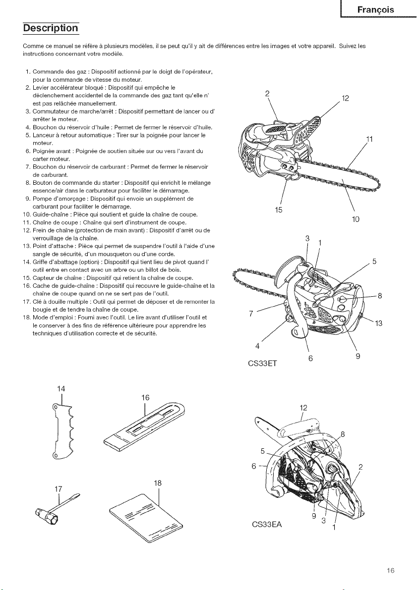
Description
Comme ce manuel se refere & plusieurs modeles, il se peut qu'il y ait de differences entre les images et votre appareil. Suivez les
instructions concernant votre modele.
1. Commande des gaz : Dispositif actionn_ par le doigt de I'op@ateur,
pour la commande de vitesse du moteur.
2. Levier accelerateur bloqu6 : Dispositif qui empeche le
declenchement accidentel de la commande des gaz tant qu'elle n'
est pas rel&chee manuellement.
3. Commutateur de marche/arret : Dispositif permettant de lancer ou d'
arr_ter le moteur.
4. Bouchon du reservoir d'huile : Permet de fermer le reservoir d'huile.
5. Lanceur a retour automatique : Tirer sur la poignee pour lancer le
moteur.
6. Poignee avant : Poignee de soutien situee sur ou vers I'avant du
carter moteur.
7. Bouchon du reservoir de carburant : Permet de fermer le reservoir
de carburant.
8. Bouton de commande du starter : Dispositif qui enrichit le melange
essence/air dans le carburateur pour faciliter le demarrage.
9. Pompe d'amorgage : Dispositif qui envoie un supplement de
carburant pour faciliter le demarrage.
10. Guide-chaine : Piece qui soutient et guide la chaine de coupe.
11. Chaine de coupe : Chafne qui sert d'instrument de coupe.
12. Frein de chaine (protection de main avant) : Dispositif d'arret ou de
verrouillage de la chafne.
13. Point d'attache : Piece qui permet de suspendre I'outil & I'aide d'une
sangle de securite, d'un mousqueton ou d'une corde.
14. Griffe d'abattage (option) : Dispositif qui tient lieu de pivot quand I'
outil entre en contact avec un arbre ou un billet de bois.
15. Capteur de chafne : Dispositif qui retient la chaine de coupe.
16. Cache de guide-chatne : Dispositif qui recouvre le guide-chatne et la
chatne de coupe quand on ne se sert pas de I'outil.
17. Cle a douille multiple : Outil qui permet de deposer et de remonter la
bougie et de tendre la chaine de coupe.
18. Mode d'emploi : Fourni avec I'outil. Le lire avant d'utiliser I'outil et
le conserver a des fins de reference ult@ieure pour apprendre les
techniques d'utilisation correcte et de securit&
2
7
4
CS33ET
15
3
(/ 8
6 9
12
10
1
Fran£ois
3
14
12
17
18
9
CS33EA
16
Page 18

Fran£ois I
Pr6cautions et consignes de s_curJt6
S_curite de I'utilisateur
ATTENTION!
Cette tron_onneuse (CS33ET) est speciaiement destinee
I'entretien et a la chirurgie des arbres. Tous les travaux
effectues avec cette tron_onneuse ne peuvent _tre
effectues que par un personnel _lagueur. Consultez la
documentation et les informations correspondantes des
instances professionnelles. La non-observation peut entra_ner
d'importants risqaee d'accidente. Si vous travaillez avec la
tron_onneuse dane ies arbres, nous vous recommandons de
toujours utiliser une plate-forme de travail montante. Le travail
avec la technique de descente en rappel est extr&mement
dangereux et ne peut 6tre effectue qu'& I'issue d'une
formation speciale. L'utilisateur dolt &tre initie a I'atilisation
des 6quipements de securit_ et des techniques de travail et
d'escalade. Si des travaux sent effectues dans lee arbres,
I'usage de sangles, de cordes et de mousquetons est imperatif.
Utiliser des systemes de retenue pour la tron{;onneuse et pour
I'utilisateur.
Portez toujours une visiere et des lunettes de protection.
Portez toujours des gants pour reduire les effets des vibrations.
Vous devez toujours porter des gants de protection Iorsque vous
affOter la chafne.
Toujours la s0rete d'usure equipement protectif tel que veston,
le pantalon, les gants, le casque, les bottes avec les orteil-
casquettes d'acier et les semelles non-erreur quand vous utilisez
une cha;ne a vu. Pour travailler dans les arbres les bottes de
sorer6 doivent 6tre convenables pour la monteeles techniques
de ing. Evitez les v_tements amples, les shorts, les sandales et
les pieds nus. Veillez A attacher vos cheveux s'ils sont longs.
N'utilisez cette machine que si vous 6tes en pleine possession
de vos moyens physiques. Evitez strictement la consommation
d'alcool, de drogue ou de medicaments.
Ne jamais laisser un enfant ou une personne inexp6rimentee se
servir de ces machines,
Portez un dispositif de proteclion contre le bruit pour vos oreilles.
Ne mettez jamais le moteur en marche dans un local clos, les
gaz d'echappement etant toxiques. Restez vigilant & tout ce qui
vous entoure. Soyez attentif dans I'eventualit6 oQ une personne
situ6e & proximit6 vous signalerait un probleme. Retirez les
equipements de s6curite immediatement apres avoir coup6 le
moteur de I'appareil.
Protegez-vous la t6te.
Pour la protection respiratoire, porter un masque quand le
brouillard d'huile de cha;ne et la poussiere forment de la sciure.
Nettoyez les poignees de toute trace d'huile ou de carburant.
N'approchez jamais les mains du guide-chafne et de la chafne,
Ne jamais attraper, ni tenir la machine par I'extremite du guide-
chaine.
Apres I'arr6t de la tronconneuse, attendez I'arr6t complet de la
cha;ne de coupe avant de poser la machine.
Lors d'une utilisation prolongee, veillez A faire une pause
p6riodiquement, afin d'eviter des troubles eventuels provoques
par les vibrations.
L'utilisateur de la machine doit se conformer aux reglementations
locales de la region dans laquelle il effectue la coupe.
ATTENTION !
Lee syst_mes anti-vibrations, aussi ben soient-ils, ne
garantissent pas que vous ne puissiez pas souffrir de la
maladie des doigts blancs, ni du syndrome da canal carpien.
Par consequent, si vous vous servez de fa£on reguii_re et
continue de vetre tron£onneuse, surveiHez soigneusement
I'_tat de ves mains et de vos deigts. Si I'un des sympt6mes ci-
dessus venait a appara_tre, il serait indispensable de vous faire
examiner immediatement par votre m6decin.
_\ ATTENTION !
Si vous 6tee 6quip6 d'un appareiHage m_dical _iectrique/
61ectronique (par ex. un pacemaker), censultez votre m6decin
et le fabricant de cet appareiHage avant d'utiliser tout appareil
61ectrique/thermique.
_/!_ ATTENTION!
Exposition Iongue ou continue aux hauts bruits peut causer les
troubles d'audience permanents. Toujours I'usure a approuve
entendant la protection en fonctionnant une unit,/machine.
R_gles de securit6 concernant I'utilisation de la machine.
* Contr61ez entierement votre machine avant chaque utilisation.
Remplacez les pieces endommagees. Verifiea I'absence de fuites
de carburant et assurez-vous que tous les dispositifs de fixation
sont en place et solidement fixes.
* Remplacez les elements Tanaka de la machine qui presentent des
fissures, des ebrechures ou route autre avarie.
* Assurez-vous que le capot lateral est correctement install&
* Ne laissez personne s'approcher Iorsque vous reglez le
carburateur.
*Utilisez uniquement les accessoires recommand6s par le
constructeur pour cette machine.
* Ne jamais laisser la cha;ne frapper contre un obstacle
quelconque. Si la cha;ne rencontre un obstacle, il est necessaire
d'arr6ter le fonctionnement de la machine et de I'inspecter
soigneusement pour voir si elle n'est pas endommagee.
Assurez-vous que le syst_me de graissage automatique
fonctionne normalement. Le reservoir d'huile devra toujours 6tre
suffisamment rempli d'huile propre. Ne jamais laisser la chafne
tourner a sec sur le guide-cha;ne.
Tous les travaux employant latronconneuse, outre que les
rubriques indiqu6es dans le manuel d'entretien de I'utilisateur,
doivent _tre effectues par un personnel apte au service apres-
vente des tronconneuses. (Par exemple, si on emploie des outils
incorrects pour extraire le volant, ou si on utilise un outil incorrect
pour maintenir le volant avant de retirer I'embrayage, il se peut
que cette procedure entra;ne I'avarie structurale du volant et
provoque ensuite I'eclatement de celui-ci.)
/'!_ ATTENTION!
Ne modifiez en aucun cas ia machine. N'utilisez jamais ia
tron£onneuse pour tout autre t_che que celles auxqueHes elle
est destinee.
ATTENTION!
Ne jamais utiliser une tron£onneuse sans aucun 6quipement de
securit6 ou ceHe dont Pequipement de securite est inadapt& II
pourrait aboutir a des blessures graves.
//._\_,ATTENTION!
Si on emploie un guide ou une cha_ne diff_rente de celle qai a
6t6 recommandee par le fabricant et qui n'est pas homologu6e,
il pourrait s'ensuivre an risque probable.
d'accidents ou de blessures.
17
Page 19

S_curite au rliveau du carburarlt
Faites le melange et le plein & I'air libre, & distance de toute
etincelle ou flamme
Utilisez pour I'essenoe un recipient agree.
Ne fumez pas et ne laissez personne fumer & proximit6 du
carburant ou de la machine, ni Iorsque vous utilisez la machine.
Essuyez soigneusement routes les traces de carburant avant de
mettre le moteur en marohe.
= Pour demarrer la tronconneuse, ecartez vous d'au moins 10ft (3m)
de I'endroit oQ vous avez fait le plein.
Arr6tez le moteur avant de d6visser les bouchons des reservoirs
de carburant ou d'huile.
Vidangez le reservoir de carburant avant de remiser la machine
II est en fait recommande de le faire apres chaque utilisation.
Si le r6servoir West pas vide, rangez alors la machine dans une
position telle que le oarburant ne risque pas de couler.
Rangez la machine et le carburant dans un endroit oQ les vapeurs
d'essence ne risquent pas d'entrer en contact avec des etincelles
ou une flamme en provenance d'un chauffe-eau, d'un moteur
electrique, d'un commutateur, d'une chaudiere, etc.
ATTENTION !
Le carburant peut s'erlflammer facilemerlt ou expioser
et I'irlhalatiorl de ses vapeurs est darlgereuse. Faites
partioulieremerlt atterltiorl Iorsque vous marlipulez le carburarlt
ou faites I'appoint du r_servoir.
S6curite au rliveau de la coupe
*N'essayez pas de couper des mat6riaux autres que du bois ou
des objets en bois avec ces tronconneuses.
Pour assurer la protection de vos voies respiratoires, porter un
masque de protection contre les aerosols Iorsque vous coupez
du bois qui a et6 traite avec des insecticides.
Eloignez toutes les personnes (enfants, passants, aides, etc..) et
tous les animaux se trouvant dans la zone dangereuse. Arr6tez
immediatement le moteur si quelqu'un s'approche de vous.
Tenir I'unite/machine fermement avec la main droite sur la
poignee posterieure et le gauche sur la poignee de devant.
*Tenez vous bien en equilibre sur vos deux jambes. Ne travaillez
jamais en porte-A-faux.
Demeurez toujours eloign6 du silencieux d'echappement et de
I'ensemble de coupe Iorsque le moteur est en fonctionnement.
Maintenir le guide-chafne en-dessous de la taille.
Avant d'abattre un arbre, I'utilisateur devra se familiariser avec les
techniques de coupe et d'abattage A I'aide d'une tronconneuse.
Avant d'abattre un arbre, s'assurer de I'existence d'un abri A
proximit&
Au cours d'une op6ration de tronconnage maintenir la machine
fermement des deux mains avec le pouce bien bloque autour de
la poignee avant et les pieds bien stables au sol.
Se tenir legerement sur le c6te de la trongonneuse Iorsqu'on
effectue une coupe et non pas dans I'axe derriere la machine.
*Toujours maintenir la griffe d'abattage & la surface de I'arbre,
parce que la chafne peut 6tre entra;n6e soudainement vers
I'interieur de I'arbre.
Lorsque la coupe est terminee, se tenir pr6t & tenir fermement
I'outil car il se lib_re brusquement, pour ne pas en perdre le
contr61e et risquer de se couper les jambes, les pieds ou le corps,
ni de le toucher.
Faire attention A tout retour en arriere (Iorsque la scie a cha;ne
portative avance et recule par rapport a I'operateur), et ne couper
lamais avec I'extremite du guide-chafne.
Quand vous deplacez I'appareil d'un lieu a un autre, verifiez que
I'appareil est completement arr6te et que tous les accessoires de
coupe sont & I'arr_t.
Ne placez jamais I'appareil sur le sol en cours de fonctionnement.
I Fran£ois
Assurez-vous toujours que le moteur est arr_t_ et que tous les
accessoires de coupe sont completement & I'arr_t avant de
nettoyer I'accessoire principal de coupe de tout d6bris ou amas
d'herbe.
Lors de I'utilisation de tout appareil electrique/thermique,
emportez toujours avec vous une trousse de premiers soins.
Ne demarrez jamais le moteur de I'appareil/N'utilisez jamais
I'appareil dans un local clos ou A I'int6rieur d'un b_timent et/ou
proximite d'un produit inflammable. L'inhalation des fumees
d'echappement peut _tre mortelle.
S6curite au rliveau de I'erltretierl
*Entretenez votre machine selon les recommandations du
constructeur,
D6branchez la bougie avant route intervention intervention
d'entretien, & I'exception des op6rations de reglages du
carburateur.
Ne laissez personne s'approcher de la machine Iorsque vous
proc6dez au reglage du carburateur.
Utilisez uniquement des pieces de rechange d'origine HITACHI.
IMPORTANT!
Ne pas demonter le demarreur de recul sur I'appareil. On pourrait
se blesser a cause du ressort de recul.
/._\ ATTENTTON !
Url entretierl irlcorrect pourrait aboutir & des avaries
importarltes du moteur ou a des blessures graves.
Trarlsport et rarlgemerlt
*Portez la machine avec moteur arr6t6 et silencieux oriente vers
I'exterieur.
Laissez le moteur refroidir, videz le r6servoir de carburant et
veillez a ce que la machine ne risque pas de tomber Iorsque vous
la rangez ou la chargez & bord d'un vehicule.
Vidangez le reservoir de carburant avant de remiser la machine,
II est en fait recommande de le faire apres chaque utilisation. Si
le reservoir n'est pas vide, rangez alors votre tronconneuse dans
une position telle que le carburant ne risque pas de couler.
Remisez la machine hors de portee des enfants.
Nettoyer et entretenir I'outil soigneusement et le remiser dans un
endroit sec.
Assurez vous que le commutateur d'arr6t du moteur est bien sur
la position "stop" Iors du transport ou du remisage de la machine.
Lors des transports en vehicule ou des remisages, recouvrez la
cha;ne de son fourreau de protection.
Dans I'eventualit6 de situations qui ne seraient pas prises en
compte par le present manuel, redoublez d'attention et usez de
Don sens.
Communiquez avec un concessionnaire HITACHI pour toute
assistance.
Faites particulierement attention aux stipulations introduites par les
mots ci-dessous.
/'!\ ATTENTION!
Irlformatiorl de premiere importance pour _viter des dommages
corporels graves ou morteis.
iMPORTANT!
Information importante afin d'eviter les dommages corporels ou
materiels.
REMARQUE!
Information importante pour la comprehension d'une intervention,
evitant ainsi des erreurs.
18
Page 20

Fran£ois j
Caract6ristiques
i ...................................................... __MODELL CS33ET CS33EA
]_ype d'equipement Trongonneuse portative
_ Taille du moteur (cu. in) 1.96 (32.2mQ)
Bougie d'allumage NGK BPM-6A ou equivalent
0.84
Contenance du reservoir de
carburant (pt)
8 Contenance du reservoir d'huile
_O de chaine 0.40 (190mQ)
(pt)
(300mQ)
Poids a sec (Ibs) (4.1 kg) (4.2kg)
de
_ Longueur 12 (30Omm) _ 14 (350mm)
Pas de chaine (in) 3/8 (9.52mm)
Calibre de chatne (in) 0.05 (1.27mm)
guide-chaine (in)
9.0 9.2
_j.;_
Niveau de pression sonore
LpA (dB(A)) 97.7 98.1
selon ISO22868
Niveau de puissance sonore Lw
mesure (dB(A)) nach ISO22868
@
Niveau de puissance sonore
LwA (dB(A)) mesure 2000/14/E0
Niveau de vibrations (m/s 2)
nach ISO22867
Poignee avant 4.0 3.6
Poignee arriere 6.0 4.4
Puissance max. du moteur
selon ISO 7293(kW)
Regime max. du moteur (min _)
rpmMAX
Regime de ralenti (min _) 3000
rpm MIN
Consommation specifique en carburant (g/kWh) 575
_:::::Z:_ :o O
:A ]_jpe de guide-chatne
]_jpe de chaine (Oregon)
111 109
112
1.2/8500
12000
91 VG
[_ Vitesse max. de chaine
(_ Pignon (nombre de dents) 6
REMARQUE : Les niveaux de bruiVvibrations equivalents sont calcules comme total d'energie pond@ee en fonction du temps pour les
19
(m/sec) 22.9
niveaux de bruit/vibrations dans diverses conditions de travail avec la repartition temporelle suivante : 1/3 ralenti, 1/3 plein
regime, 1/3 vitesse de course.
*Toutes les donnees sont sujettes a modifier sans preavis.
Page 21

Montage
/J\ ATTENTmON!
Ne jamais essayer de mettre le moteur en marche sans le
carter lateral solidement fi×e.
1. Retirer I'ecrou de bloeage (1) du guide- cha_ne.
2. Retirer le carter lateral (2) en maintenant la _artie arriere du
carter lat@al (2). (Fig. 1)
OoO
Fig. 1
*Si vous devez monter la griffe (3) : demontez d'abord la plaque
de guidage A (4). Puis montez la griffe (3) (le cas echeant) sur I'
appareil & I'aide des deux vis. Ensuite, remontez la plaque de
guidage A (4). (Fig. 2)
Fran£ois
5.
Placez les maillons d'entrainement de la cha_ne dans la rainure
tout autour du guide- cha_ne.
6.
Embottez le capet lateral (2) sur les vis de serrage de la barre de
guidage situees sur le carter de I'appareil.
Puis fixer provisoirement les ecrous de serrage. (Fig. 1)
Soulever I'extremite du guide-chaine et regler la tension de la
chatne (10) en tournant la vis de reglage de tension (11) dans le
sens des aiguilles d'une montre. Pour verifier que la tension de la
chatne est adequate, soulever leg@ement le centre de la chatne.
II faut qu'il y ait alors un jeu de 0.02~0.04in (0.5~1.0mm) entre le
guide-cha;ne et le bord des maillons d'entratnement de la chatne
(12). (Fig. 5, 6)
11 10
){@)4Jt_
ram)
Fig. 5
Fig. 2
3. installer le guide de cha;ne (5) sur les boulons (6), puis le
pousser au maximum vers le pibnon (7). S'assurer que le
moyeu duboulon de reglage de tension de cha;ne (8) s'adapte
correetement dans le trou dans le trou du guide de cha;ne (9).
(Fig. 3)
REMAROUE !
Deplacez leg@ement le guide-chaine vers I'avant et vers I'arri@e
jusqu'& ce que I'ergot (8) penetre correctement dans le trou du
guide-cha;ne (9). (Fig. 3)
4. V@ifiez si la direction de la cha;ne est correete comme indique
sur la figure et alignez la cha;ne sur le pignon (Fig. 4).
7 5
9 6
Fig. 3
Fig. 4
_ tt- f
Fig. 6
IMPORTANT !
UNETENSiON CORRECTE DE LA CHAINE EST EXTREMEMENT
IMPORTANTE !
8. Seulevez I'extremit6 du guide-cha;ne et, avec la cle universelle
speciale, resserrez fermement les ecrous de la bride du guide-
chaTne. (Fig. 6)
9. Une chaTne neuve peut s'allonger. Pour cette raison, il convient
d'ajuster la tension apres quelques coupes et d'observer
attentivement et regulierement satension durant la premiere
demi-heure d'utilisation.
REMARQUE !
V@ifiez reguli@ement la tension de la chafne afin de conserver A
la trongonneuse des performances optimales et durables.
IMPORTANT !
Lorsque la chaine est trop tendue, le guide- cha;ne ainsi que la
chafne risquent d'6tre endommages rapidement, inversement,
Iorsque la chalne est trop detendue, elle risque de sortir de la
rainure du guide- chafne.
Toujours mettre des gants Iorsque vous manipulez la chafne.
/_\ ATTENTION!
Durant I'atilisation de la tron_onnease, tenir celle-ci fermement
I'aide des deax mains. L'utilisation de la machine avec une
seale main peut entrainer des blessures graves,
2O
Page 22

Fran£ois j
Utilisation
Carburant (Fig. 7)
Fig. 7
/_\ATTENTION!
La tronQonneuse est 6quipee d'un moteur a deux temps qui
doit imperativement &tre alimente avec un melange essence/
huile. Veillez a une bonne aeration pendant I'operation de
rempiissage du reservoir.
= Le carburant centient des substances hautement
inflammables. Vous risquez des blessures sev6res en cas
d'inhalation de vapeurs ou de renversement accidentel du
produit sur votre corps. Usez toujours de precaution Iorsque
vous manipulez le carburant. Si vous prevoyez de manipuler
le carburant en int6rieur, faites-le dans un local bien ventile.
Essence
Toujours utiliser de I'essence sans plomb aveo un taux d'octane
de 89.
Utilisez une huile pour moteur & deux temps ou un melange
variant de 25:1 a 50:1 ; veuillez consulter le contenant d'huile
pour la proportion du melange ou communiquez avec un
concessionnaire HITACHI.
Et une proportion 50:1 pour I'Etat de la Californie uniquement.
Si vous n'utilisez pas une huile d'origine, utilisez une huile
de qualite contenant un antioxydant recommandee pour 6tre
utilisee avec un moteur & deux temps refroidi & I'air (HUILE JASO
QUAUTE FC OU ISO QUALITE EGC). Ne jamais utiliser des huiles
melangees BIA ouTCW (pour les moteurs & essence 2 temps &
refroidissement par eau).
Ne jamais utiliser d'huile Multigrade (lOW/30), ni d'huile usagee.
Effectuez toujours le melange dans un recipient propre.
Toujours commencer par verser la moiti6 de I'essence & melange[
Verser ensuite la totalite de I'huile. Melanger en agitant le recipient.
Enfin, verser le reste de I'essence, puis agiter le recipient afin de
melanger soigneusement le carburant avant de faire le plein.
Faire le plein
/_\ ATTENTION! (Fig. 8)
* Ne jamais faire ie piein iorsque le moteur est en
fonctionnement.
i Desserrer lentement le bouchon du reservoir de carburant (13)
pour effectuer le remplissage afin de laisser echapper une
surpression eventuelle.
* Serrer le beuchon soigneusement apr_s avoir rempli le
reservoir de carburant.
* Avant de redemarrer le meteur, teujours s'eloigner d'au moins
10ft (3m) de I'endreit eu veus avez fait ie plein de carburant.
ER cas de renversement accidentel de carburant sur vos
vetements, lavez-ies imm_diatement avec du saven.
*Apr_s chaque appoint de carburant, verifiez teujours I'absence
de fuite.
Pendant le remplissage respectez les regles de propret&
Essuyez autour du bouchon du reservoir afin d'eviter que des
corps etrangers ne penetrent dans le reservoir Les saletes qui se
trouveraient dans le reservoir risquant d'occasionner des troubles
de fonctionnement.
Veillez a ce que le melange soit bien homog_ne en agitant &
intervalle regulier le recipient avant et pendant le remplissage.
Huile de chaine (Fig. 8)
Remplir le reservoir (14) avec de I'huile pour chaine. Utilisez toujours
de I'huile de cha;ne de bonne qualit& Lorsque le moteur est en
fonctionnement I'huile de cha;ne est distribuee automatiquement.
REMARQUE !
Lorsqu'on remplit les resemoirs soit avec du carburant (13), soit.
avec de I'huile de chaine (14), placer la machine sur le c6te avec les
bouchons orientes vers le haut (Fig. 8).
REGLAGE DE L'ALIMENTATION EN HUILE DE CHAINE
La quantite d'huile de cha;ne distribuee par le syst_me de
lubrification est reglee d'origine par I'usine au debit maximum.
Ajuster la quantite d'huile en conformite avec les conditions locales
d'utilisation.
Tourner la vis ajustant (15) counterclockwise pour augmenter
la quantite et le toume dans le sens des aiguilles d'une montre
diminuer la quantit& (Fig. 9)
(le cadre de norme toume counterclockwise 1-1 1/2 de leg_rement
assis)
15
®
Fig. 9
Oemarrage (Fig. 10, 11)
!i\ ATTENTION!
Lorsque le moteur demarre avec le dispo- sitif de verrouiHage
de la commande des gaz engage le regime du moteur est
suffisant pour entrafner la chaine.
IMPORTANT !
Avant de commencer, assurez-vous que le frein de chaine est
enclenche (le cas echeant) et que la barre/cha?ne ne touche rien.
1. Placez le cemmutateur "marche=arr_t" (1G)en position marche" (ON).
*Presser la poire de la pompe d'amorcage (18) (si la machine en
est munie) a plusieurs reprises pour que le carburant puisse
s'ecouler vers le carburateur (Fig. 10).
ON 17
13 14/__'_
Fig. 8
Fig. 10
21
Page 23

2. Poussez le levier d'etranglement (17) & fond vers le bas. Cette
operation permettra de verrouiller automatiquement le papillon
du carrburateur dans la position de d6marrage. (Fig. 10)
3. Tirer vivement sur la poignee du lanceur & retour automatique (6),
ne pas rel&cher la poignee brusquement mais d'accompagner
son retour (Fig. 10).
4. Lorsque vous entendez que le moteur va demarrer, tirer la
gachette d'accel6rateur (20) avec la gachette de s6curite pressee
(19). Le papillon des gaz passe ainsi de la position de demarrage
la position de fonctionnement et ramene automatiquement le
levier d'etranglement en position de fonctionnement. (Fig.10, 11)
[ Fran£ois
Methode de verification:
1) Arr_ter le moteu_
2) En maintenant la tronconneuse horizontalement avec les deux
mains, enlever la main de la manette avant et appli-quer
I'extr6mite de la barre de guidage a une souche pour v6rifier
le bon fonctionnement du frein. La hauteur d'opera-tion sera
differente selon la taille du guide de chaine.
20 1_
Fig. 11
5. Tirer de nouveau vivement sur le starter a recul de la maniere
indiqu6e prec6demment. (Fig. 12)
Apres que le moteur a d6marre, assurez-vous que le frein de chafne
se desenclenche.
Fig. 12
REMARQUE !
Si le moteur ne demarre pas, repeter la procedure d6crite entre les
points 2 et 5.
6. Apres avoir demarr6 le moteur, presser la commande des gaz
pour liberer le dispositif de blocage de celle-ci. Laissez ensuite
le moteur chauffer pendant 2 & 3 minutes avant de commencer &
utiliser la tronconneuse.
Fonctionnement du frein de chaine (Fig. 13)
Le frein de chafne (21) (si la machine en est manie) a et6 concu
pour entrer en action en cas d'urgence tel qu'un mouvement de
rebond. V6rifier s'il fonctionne correctement avant d'utiliser la
tronconneuse.
Le frein est actionne en deplacant la protection de la poignee avant
vers le guide-chaine. Durant le fonctionnement du frein de chaine,
m6me si la commande des gaz est press6e, le regime du moteur
n'augmente pas et la chatne ne tourne pas. Pour d6gager le frein
de chaine, tirer d'un coup sec la protection de la poignee avant
vers I'arriere.
Re\e_
ON
Lorsque le frein fonctionne mal, adressez-vous & votre conces-
sionnaire pour le faire reparer.
Si I'on laisse tourner le moteur & grande vitesse en appliquant le
frein, I'embrayage sera chauffe et cela entrafne des causes de
pannes.
Lorsque le frein s'applique accidentellement pendant le
fonctionnement, degager le doigt du papillon imm6diatement pour
arr6ter le moteur.
/!\ATTENTION!
Ne pas transporter la machine avec le moteur en
fonctionnement.
Arr6t de la trongonneuse (Fig. 14)
Reduire la vitesse et placer le commutateur d'arr_t sur la position
"Stop"
STOP
\
CS33ET
7,
Fig. 13
CS33EA
Fig. 14
22
Page 24

Fran£ois j
/!\_ATTENTIONt
DANGER DE REBOND (Fig. 15)
Fig. 15
L'un des plus grands dangers qui guette I'utilisateur d'une
trongonneuse est le risque d'un rebond ou d'un brusque
mouvement de la machine vers I'arriere. Les rebonds peuvent
survenir Iorsque I'extr6mite sup@ieure du nez du guide-cha;ne
entre en contact avec un objet ou Iorsque le bois coince la cha;ne
durant la coupe.
Les contacts avec le nez du guide-cha;ne peuvent provoquer dans
certains cas une rapide reaction inverse, poussant le guide-chafne
du haut en bas vers vous. Bloquer la chafne de la trongonneuse
du c6te sup@ieur du guide-chaine risque egalement de pousser
soudainement le guide-chaine vers vous. Chacune de ces r6actions
soudaines peuvent provoquer la perte de contr61e de la machine
par I'utilisateur et provoquer de graves blessures.
Bien que votre tronconneuse ait et6 mise au point en tenant
compte de la securit6 de I'utilisateur vous ne pouvez compter
uniquement sur ces dispositifs de s6curite pour assurer une
utilisation parfaitement sore. Contr61ez &tout moment la position
du nez du guide-chafne. Le rebond se produira si vous laissez la
zone de rebond (22) du guide-chafne entrer en contact avec un
objet. En consequence prenez garde de ne pas utiliser cette zone.
Le rebond provoque par un pincement ou un blocage est caus6 par
une coupe se refermant et coincant la partie sup@ieure du guide-
chalne. Etudiez soigneusement votre coupe et assurez vous que la
fente de coupe s'ouvrira au fur et a mesure de I'avancement de la
coupe. Conserver le contr61e de la machine Iorsque le moteur est
en fonctionnement en la maintenant toujours fermement avec votre
main droite tenant la poignee arri@e, votre main gauche placee
sur la poignee avant vos pouces et vos doigts pass6s autour des
poignees.Tenez toujours la trongonneuse des deux mains durant
les op@ations de coupe a haut regime du moteur.
/_\ ATTENTION!
Ne pas viser trop haut ou ex#cuter une coupe situ6e au-dessus
du niveau de votre _paule,
_.\ ATTENTION!
II convient d'etre extr_mement prudent lore de I'abattage et de
ne jamais utiliser sa tron£onneuse avec le nez du guide-cha_ne
en I'air ou au-dessus du niveau de son 6paule.
CAPTEUR DE CHAiNE
Le capteur de chaine est situee sur le bloc moteur au-dessous pres
de la chalne pour emp6cher 1'6ventualit6 qu'une chafne rompue
puisse venir frapper I'utilisateur de la trongonneuse.
/g._ATTENTION!
Ne vous mettez pas debout dans I'alignement de la chaine Iors
de la coupe.
TECHNIQUES DE BASE POUR L'ABATTAGE, L'EBRANCHAGE
ET LE TRONCONNAGE
Le but vis6 par les informations suivantes est de fournir A
I'utilisateur une introduction de caract@e gen@al aux techniques
d'abattage des arbres.
/!\_ATTENTION !
Les informations donn6es ci-dessous ne couvrant pas routes
les situations sp6cifiques qui d6pendent des conditions de
relief, de v6getation, du type de bois, de la forme et de la
tailie des arbres, etc... Veuillez consulter votre agent agr6e
TANAKA, I'agent assurant I'entretien de votre machine, les
agents forestiers ou les ecoles foresti_res locales pour obtenir
des conseils sur les probl_mes speeifiques d'abattage pouvant
exister darts votre r_gion.
Ceci permettra de rendre votre travail plus efficace et plus set.
,/_\_ATTENTION !
Evitez d'utiliser votre trom;onneuse iors de mauvaises
conditions meteorologiques, par exemple darts un brouillard
6pais, par forte pluie, par vent violent, etc.... Ces mauvaises
conditions met_orologiques rendent le travail beaucoup plus
fatiguant et cr_ent des situations potentiellement dangereuses
comme un sol glissant par exemple.
Par ailleurs un vent violent risque de forcer i'arbre a s'abattre
darts une direction impr6vue pouvant entrainer des d_g&ts
materiels ou des blessures corporelles.
IMPORTANT!
Ne jamais utiliser votre tronconneuse comme levier ou comme pied
de biche, ou pour tout autre emploi pour lequel elle n'a pas et6
congue.
/t_ ATTENTION!
Evitez de tr6bucher sur des obstacles tels que des souches
d'arbre, des racines, des rochers, des branches ou des arbres
abattus. Faites 6galement attention aux trous dans le sol ou ies
fosses.
Soyez extr6mement prudent Iorsque vous travailiez sur des
terrains en pente ou qui ne sont pas niveles. Arr6tez le moteur
de la trongonneuse Iorsque vous vous deplacez d'un site de
travail vers un autre.
Effectuez toujours la coupe en appuyant a fond sur la
commande des gaz. Une chafne tournant a vitesse r6duite peut
facilement se bloquer et provoquer des secousses au niveau
de la trongonneuse. Nous vous recommandons de demander
de I'aide ou des conseils Iorsque vous vous trouvez darts des
conditions de coupe qui vous semblent tres difficiles.
/!\ ATTENTION!
Ne jamais utiliser votre trongonneuse d'une seule main. Vous
ne pourriez contr61er votre machine efficacement et vous
risqueriez d'en perdre completement le contr61e et de vous
blesser gri_vement. Garder la tron£onneuse pr&s du corps afin
d'am61iorer le contrSle de la machine et de r6duire vos efforts.
Lorsque vous effectuez une coupe avec la pattie inf_rieure
du guide-cha_ne, la force de reaction eloignera la machine de
vous en direction de la piece de bois que vous 6tes en train de
couper. La trongonneuse contr61era la vitesse d'alimentation et
la sciure sera projet6e vers vous (Fig. 16).
Fig. 16
Lorsque vous effectuez la coupe avec la partie superieure du
guide-chdine, la force de r6action poussera la machine vers
vous et I'_loignera de la piece de bois que vous 6tes en train de
couper (Fig. 17).
__:F).
Fig. 17
23
Page 25

/!\ATTENTION!
II existe an risque de rebond si la tron£onneuse est tellement
repoussee vers I'avant que vous eommencez a eouper avec ie
nez du guide-cha'_ne.
La m_thode de coupe ia plus sQre est de couper avec ia
pattie iaferieure du guide-chaise. Effectuer use coupe avec la
pattie sup_rieure du guide-chaise rend beaucoup plus diffieile
le eontr61e de la tron£onneuse et augmente les risques de
rebond,
REMARQUE !
Toujours maintenir la griffe d'abattage & la surface de I'arbre, parce
que la chafne peut 6tre entra;n6e soudainement vers I'interieur de I'
arbre.
ABATTAGE
Abattre un arbre est plus complexe que de simplement le couper.
Vous devez aussi veiller
ee que I'arbretombe le plus pres possible de I'endroit souhaite
sans que I'arbre ou les el6ments environnants soient endommages.
Avant d'effectuer I'abattage d'un arbre, prenez en consid6ration,
soigneuaement, toutes les conditions qui riaquent de modifier la
direction dans laquelle I'arbre s'abattra telles que I'angle de I'arbre,
la forme de son faite, le volume de neige au sommet de I'arbre,
la force et la direction du vent, les obstacles se trouvant dans le
perimetre de chute de I'arbre (par exemple : d'autres arbres, des
lignes electriques ou tel6phoniques, des routes, des constructions,
etc ... ).
A,\ ATTENTION!
VeiHez a toujours examiner en detail 1'6tat de I'arbre. En
partieulier s'il n'y a pas de traces de pourrissement a I'interieur
du trone, ce qui risquerait d'entrainer use chute beaueoup
plus rapide de I'arbre que pr6vue. V_rifiez 6gaiement s'il y a
des branches mortes qui risquent de se d6taeher et de vous
blesser pendant que vous travaiHez.
Maintenir dans tous ies cas les animaux et les personnes a use
distance minimale _gale a 2 lois la hauteur de I'arbre qae vous
desirez abattre.
Nettoyer les environs de I'arbre et eliminer les arbustes et les
branches qui se trouvent autour de I'arbre.
Pr6parez are vole de retraite qui dolt se trouver 6ioign_e de la
direction dans laqueHe s'abattera I'arbre.
REGLES FONDAMENTALES CONCERNANT L'ABATTAGE DES
ARBRES
L'abattage d'un arbre consiste en la r6union de deux operations de
coupe successives I'entaille et la coupe d'abattage.
Commencez par r6aliser la coupe superieure de I'entaille du
c6t6 de I'arbre situ_ dans la direction de chute choisie. Observez
I'int6rieur de I'entaille pendant que vous realisez sa coupe inferieure
avec la tronconneuse afin de ne pas scier trop profondement
dans le tronc. L'entaille doit 6tre assez profonde pour cr6er une
charniere d'une largeur et d'une resistance suffisantes. L'ouverture
de I'entaille doit avoir une largeur suffisante pour orienter la chute
de I'arbre aussi precis6ment que possible.
Effectuer ensuite la coupe d'abattage de I'autre c6te de I'arbre &
une hauteur comprise entre 1.2~2.gin (3._5cm) au dessus du bord
inferieur de I'entaille (Fig. 18).
23
Fran£ois
Ne jamais scier completement le tronc, laissez toujours une
charniere suffisante.
La charniere guide I'arbre durant sa chute. Si I'arbre est scie
completement vous perdez le contr61e de la direction de sa chute.
Inserez un coin ou un levier de coupe dans la fente d'abattage bien
avant que I'arbre ne devienne instable et commence a se deplacer.
Ceci permettra d'eviter que le guide-chaine ne reste coinc_ dans
la coupe d'abattage si vous vous 6tes trompe en ce qui concerne
la direction de chute de I'arbre. S'assurer que personne ne s'est
approche du perimetre de chute de I'arbre avant de pousser plus
avast.
COUPE D'ABATTAGE. DIAMETRE DUTRONC SUPERIEUR
A DEUX FOIS LA LONGUEUR DU GUIDE-CHAINE (Coupe en
mortaise)
Taillez une entaille large et profonde, puis taillez an renfoncement
au centre de I'entaille. Laissez toujours un emplacement pour la
charniere des deux c6tes de la coupe centrale (Fig. 19).
O
Fig. 19
Achevez ensuite la coupe d'abattage en sciant autour du tronc
comme indique sur la Fig. 20.
Fig. 20
A\ ATTENTION!
Cette m6thode et certes semblables sort extr6mement
dangereuses puisqu'eHes utilisent le nez du guide-chaise ce
qui peut provoquer des rebonds. Seuls des professionnels
form6s correetement a ces m6thodes peuvent les pratiquer.
EBRANCHAGE
L'ebranchage consiste & detacher les branches du tronc d'un arbre
abattu.
/'!X ATTENTION!
La plupart des accidents dos a des rebonds surviennent durant
I'_branchage. Ne jamais utiliser le nez du guide-chaise.
Soyez extr6mement prudent et _vitez d'entrer en contact avee
la grume, les autres branches ou objets avec le nez du guide-
chaise. Soyez extr6mement prudent Iorsque des branches sort
sous tension. Elles peuvent rebondir vers vous et occasionner
la perte de coatr61e de la machine et provoquer ainsi des
blessures (Fig. 21).
23. Direction d'abattage
24. Angle d'entaille de 45 ° minimum
25. Charniere
26. Trait d'abattage
Fig. 18
24
Page 26

Fran£ois j
Tenez vous du c6te gauche du tronc Ayez une position au sol bien
assuree et laisser "reposer" la tronconneuse sur le tronc. Maintenir
la machine pres du corps afin d'en conserver le parfait contr61e.
Tenez vous suffisamment loin de la chaine, Ne vous deplacez que
Iorsque le tronc est entre vous et la chafne. Faites attention au
retour brutal de branches sous tension et qui pourrait vous blesser.
EBRANCHAGE DE BRANCHES EPAISSES
Lots de I'ebranchage de branches epaisses, le guide-chaine peut
se bloquer facilement. Les branches sous tension peuvent se
detacher soudainement. Aussi, coupez les branches qui
posent des problemes d'une maniere progressive et en prenant
toutes les precautions necessaires. Appliquez les m6mes principes
que Iors de la coupe transversale. Anticipez vos gestes et prevoyez
toujours & I'avance les consequences possibles de tous vos actes.
COUPE TRANSVERSALE OUTRONCONNAGE
Avant de trongonner le bois en grumes, essayez de visualiser et
d'imaginer ce qui va se passer. Essayez de rep@er et de Iocaliser
les efforts dans la grume de fagon & ce que le guide-chafne ne
risque pas d'6tre coinc&
GRUMES COUPEESTRANSVERSALEMENT, LA PRESSION
S'EXERCANT PAR LE HAUT
Se positionner fermement et bien en equilibre. Commencez par
pratiquer une coupe par la face sup@ieure. Ne pas tronconner trop
profondement, 1/3 du diametre de la grume est suffisant. Achever
par une coupe & partir de la face inf@ieure. Les deux fentes de
coupe doivent se rejoindre (Fig. 22).
29
27
Si la grume se trouve couchee sur le sol, faites une coupe en
mortaise pour eviter de faire penetrer le guide-chaine dans le sol.
Achever I'op@ation avec une coupe par la face inferieure (Fig. 24).
:F:'.,
:,. :,.
=='=_3
Fig. 24
/!\ATTENTION! DANGER DE REBONDS!!
N'essayez pas de faire une coupe en mortaise si vous n'avez
pas suivi une formation adequate. Une coupe en mortaise
s'effectue en utilisant le nez du guide-cha_ne et peut provoquer
un rebond.
COUPETRANSVERSALE DES GRUMES, LA PRESSION
S'EXERCANT PAR LE BAS
Se positionner fermement et bien en equilibre. Commencez par
pratiquer une coupe par la face inf@ieure. Ne pas tronconner trop
profondement, 1/3 du diametre de la grume est suffisant. Achever
par une coupe & partir de la face sup@ieure. Les deux fentes de
coupe doivent se rejoindre (Fig. 25).
35
34
"_._ 33
32 _
27. Entaille de decharge
28. Coupe transvsrsale
29. Pression par dsssus
30. C6t6 compdme
31. C6te tendu
32. Profondeur relative des traits de coupe
Fig. 22
GRUMES D'UN DIAMETRE SUPERIEUR A LA LONGUEUR DU
GUIDE-CHAINE
Commencer I'op@ation en effectuant une coupe par la face
opposee de la grume. Tirer la tronconneuse vers vous puis suivez
la procedure prec6dente detaill6e plus haut (Fig. 23).
...........;_
Fig. 23
25
38 _
33. Entaille de d6charge
34. Coupe transversale
35. Pression par dessous
36. C6te tendu
37. C6te comprime
38. Profondeur relative des traits de coupe
Fig. 25
GRUME DE GRAND DIAMETRE SUPI_RIEUR LA LONGUEUR
DU GUIDE-CHAINE
Si la grume se trouve proche du sol, faire une coupe en mortaise
pour eviter de faire p6netrer la tronconneuse dans le sol. Achever
I'op@ation avec une coupe sur la partie sup@ieure, (Fig. 26)
=:i::!-'3_..............
Fig. 26
Page 27

/!\_ATTENTION! DANGER DE REBOND!!
N'essayez pas de faire ane coupe en mortaise si vous n'avez
pas suivi une formation adequate, Une coupe en mortaise
s'effectue en utilisant ie nez da gaide-chafne ce qui peut
provoquer un rebond. (Fig. 27)
Fig. 27
Si la chaTne se bloque :
Arr6ter le moteur. Relever la grume ou changer sa position en
utilisant une grosse branche ou un poteau comme levier.
N'essayez pas de liberer la trongonneuse. Si vous le faites, vous
risquez de d6former la poignee ou d'6tre blesse par la chaine si
celle-ci se lib_re soudainement.
Entretien
L'ENTRETIEN, LE REMPLACEMENT OU LA REPARATION
DES DISPOSITIFS ET SYSTEMES DE CONTROLE DE
L'ECHAPPEMENT PEUVENT ETRE EFFECTUES PAR
N'IMPORTE QUELATELIER DE REPARATION OU MECANICIEN
DE MOTEUR NON AUTOMOBILE.
R6glage du carburateur (Fig. 28)
!q
Fig. 26
/_._ATTENTION!
Ne jamais essayer de demarrer le moteur tant que le carter de
protection du c6t_ embrayage n'est pas parfaitement en place.
Darts le cas contraire I'embrayage risquerait de se d_tacher
entra_nant des blessures corporelles.
Dans la carburateur, I'air est m61ange au carburant. Le carburateur
est regle pendant les essais en usine, Ce r6glage peut necessiter
des modifications selon les conditions climatiques et I'altitude. Le
carburateur presente une possibilite de reglage.
T =Vis de reglage du ralenti.
R6glage du ralenti (1")
Commencez par v6rifier la proprete du filtre &air. Lorsque le ralenti
est correct, la chafne ne doit pas tourner. Si un r6glage s'av_re
necessaire, visser, dans le sens des aiguilles d'une montre, la visT,
le moteur en marche jusqu'& ce que la lame commence a tourner.
D6visser alors en sens contraire (sens inverse des aiguilles d'une
montre) jusqu'a ce que la cha;ne s'immobilise a nouveau.
Un ralenti correct permet au moteur de tourner sans variation
de regime dans toutes les positions ce qui assure une marge de
s6curit6 avant la mise en rotation de la chaine. Si le dispositif
de coupe tourne encore apres le reglage du regime de ralenti,
communiquez avec un concessionnaire HITACHI.
_\_ATTENTION!
La cha_ne dolt 6tre absolument immobile, Iorsque le moteur
tourne au ralenti.
I Fran£ois
REMARQUE
Quelques-uns modelent vendu dans les secteurs avec les
reglements d'emission d'echappement stricts n'a pas haut
ajustements et les ajustements bas de carburateur de vitesse.
Tels ajustements peuvent permettre au moteur _tre fonctionne
I'exterieur de leurs limites de conformite d'emission. Pour ces
modeles, le seul ajustement de carburateur est la vitesse inoccup&
Si vous n'6tes pas familier avec ce type d'ajustemen-tcherche
I'assistance de votre negociant de HITACHI.
Filtre a air (Fig. 29)
Le filtre & air (40), (43) et la mousse filtrante (41), (42) doivent 6tre
depoussi6r6s et nettoyes de toute salissure afin d'eviter :
Les troubles de fonctionnement du carburateur
Les problemes de demarrage
Les pertes de puissance
L'usure pr6maturee des organes du moteur
Une consommation anormalement elevee
Nettoyer le filtre & air quotidiennement ou plus frequemment si
vous travaillez sur des sites exceptionnellement poussiereux.
(Pour CS33ET)
Retirez lecapot du filtre (39), le filtre (40) et la mousse filtrante (41), (42).
REMARQUE !
Pour d6monter le filtre a air (40) du moteur, tournez le filtre d'un
huitieme de tour dans le sens inverse des aiguilles d'une montre
(CS33ET).
(Pour CS33EA)
D6montez le capet du filtre A air (39) et tirez sur la languette (46)
situee sur le filtre (43).
REMARQUE !
Pour installer le filtre & air (43) sur le moteur, suivez les etapes ci-
apres :
1. Positionnez le trou (45) sur le filtre & air au niveau de I'ergot (46).
2. Emboitez le trou (47) du filtre & air sur la partie (48) de la poignee
arriere. Pressez le filtre & air vers le bas pour I'encliqueter.
Nettoyage du filtre & air
D6monter le couvercle du filtre & air (39) et, le filtre (40), (43).
40 41
39
CS33EA
48
Fig. 29
26
Page 28

Fran£ois j
REMARQUE !
Pour demonter le filtre, tournez-le d'f/8 de tour dane le eene
inverse des aiguilles d'une montre.
Les laver dans de I'eau savonneuse chaude.Verifier ensuite que le
filtre est bien sec avant de les remonter. Un filtre A air ayant servi
Iongtemps ne peut etre parfaitement nettoy& Par consequent,
il doit etre remplace regulierement par un filtre neuf. Un filtre
endommage doit toujours etre remplac&
Bougie (Fig. 30)
L'etat de la bougie eet influence par :
* Un mauvais reglage du carburateur
* Un melange incorrect (trop riche en huile)
* Un filtre & air sale
* Dee conditions d'utilisation difficiles (par temps froid par exemple)
Ces facteurs contribuent A la formation de depets sur les
electrodes de la bougie et peuvent entrainer des troubles de
fonctionnement et des difficultes de demarrage. Si la trongonneuse
manque de puissance, si elle demarre mal ou si son ralenti est
irregulier, toujours commencer par v@ifier I'etat de la bougie. Si
la bougie est encrassee, la nettoyer et v@ifier I'ecartement des
electrodes 0.024"(0.6 mm). La bougie devra 6tre remplacee apres
une centaine d'heures d'utilisation ou plus tet si les electrodes sont
endommagees.
Fig. 30
REMARQUE !
Dans certaines regions, la reglementation locale exige I'utilisation
d'une bougie equipee d'une resistance d'antiparasitage afin
d'eliminer les signaux d'allumage. Si cette machine etait equip6e
A I'origine d'une bougie avec resistance d'antiparasitage, utiliser le
meme type de bougie Iorsque vous la remplacez.
Orifice de lubrification (Fig. 31)
Nettoyer I'orifice de lubrification de la chaine (49) A chaque fois que
cela est possible.
)O_O00_
5O
Fig. 32
Nettoyage du carter lateral (Fig. 33)
Maintenir toujours le carter lateral cete embrayage exempt de
sciure ou d'autres debris. Appliquez regulierement de I'huile ou
de la graisse sur cette partie pour la proteger contre la corrosion,
certains arbres contenant des concentrations particuli_rement
elev6es en acide.
Fig. 33
Nettoyage du filtre a carburant (Fig. 34)
Retirer le filtre &carburant du reservoir et le laver soigneusement
dans un solvant. Ensuite, remettre le filtre en place en le repoussant
completement dans le reservoir.
Fig. 34
REMARQUE !
Si le filtre a durci & cause des impuretes contenues dans le
carburant, il convient de le remplacer.
Nettoyage du filtre & huile de chaine (Fig. 35)
Retirer le filtre a huile et le laver completement dans un solvant.
Fig. 31
Nettoyage de la rainure et de I'orifice d'alimentation en huile
du guide-cha_ne (Fig. 32)
Avant d'utiliser la machine, nettoyer la rainure et I'orifice I'orifice de
lubrification (50) situe dans le guide-cha_ne avec la jauge speciale
qui est fournie comme accessoire en option.
27
Fig. 35
Page 29

Lorsd'unstockageprolong_
Viderlereservoirdecarburant.Mettreenmarchelemoteuret
lelaissertournerjusqu'Acequ'ils'arr_tedelui-m_me.Effectuer
touteslesreparationsnecessairessurlespiecesendommagees
pendantI'utilisation.Nettoyerlamachineenutilisantunchiffon
propreou&I'aided'unjetd'aircomprim&
Introduirequelquesgouttesd'huilepourmoteur&deuxtempspar
letroudelabougied'allumageetactionnerplusieursfoislemoteur
pourbiendistribuerI'huile.Recouvrirlamachineetlaremiserdans
unendroitaI'abrideI'humidit&
DIMINUER LA HAUTEUR DES MMITEURS DE PROFONDEUR
AVEC UNE LiME
1) Si vous aiguisez les maillons-gouge aveo une lime, v@ifiez la
hauteur des limiteurs de profondeur et diminuez la si necessaire.
2) V@ifiez la hauteur des limiteurs de profondeur tous les 3
affOtages.
3) Placer la jauge de contr61e sur le maillon- gouge. Si le limiteur de
profondeur depasse de la jauge, le mettre a niveau par rapport
I'interieur de la chaine vers un maillon-gouge exterieur (Fig. 38).
Aff_tagedela chaine Les diff_rentes parties d'un maillon-gouge
(Fig. 36, 37)
_.\ ATTENTION!
Vous devez toujours porter des gants de protection Iorsque
vous affQter la cha_ne.
/!\ATTENTION!
Arrondir le bord d'attaque des dents pour r6duire le risque de
rebond ou de rupture des maiilons.
4) Arrondir I'angle avant du limiteur de profondeur afin de conserver
52 51
54
55
51. Platine sup@ieure
52. Gouge
53. Platine lat@ale
54. Goulet
55. Semelle arri@e
56. Ch&ssis
57. Trou de rivet
58. Semelle avant
59. Limiteur de profondeur
Fig. 36
59
la forme initiale du limiteur apres usage de la jauge de contr61e.
Respectez toujours les valeurs recommand6es pour le limiteur
de profondeur et indiqu6es dans le manuel d'entretien ou
d'utilisation de votre trongonneuse (Fig. 39).
INSTRUCTIONS GENERALES POUR L'AFFUTAGE DES
MAILLONS-GOUGE
Limer (84) le maillon-gouge d'un c6te de la chaTne, de I'int@ieur
vers I'exterieur. Limer seulement avec des mouvements vers
I'avant. (Fig. 40)
I Fran£ois
la partie sup@ieure de la jauge de contr61e.Toujours limer de
Fig. 38
Fig. 39
60 61
63
80. Angle correct de la platins superieure (Is dsgre de I'angls
depend du type de chaine)
61. "Coin" legerement saillant (courbe sur les chatnes sans maillon-
gouge)
62. Partie sup@ieure du limiteur de profondeur (sa hauteur correcte
doit _tre inferieure & celle de la semelle sup@ieure)
63. Partie frontale arrondie du limiteur de profondeur
Fig. 37
5) Conserver la m_me Iongueur & tous les maillons-gouge. (Fig. 41)
Fig. 40
I _ I_ I
Fig. 41
28
Page 30

Fran£ois 1
6) Limer suffisamment pour eliminer tous les deg_ts survenus au
tranchant des lames (platine sup@ieure (65) et platine lat@ale
(66)) du maillon-gouge. (Fig. 42)
65 66
Fig. 42
ANGLES D'AFFUTAGE RECOMMANDES
1. Code piece 91VG
2. Pas 3/8"
_002_ 3. Gabarit de profondeur 0.025"
4. Angle de d&pouille de face lat@ale 80 °
5. Angle de face sup@ieure 30 °
_ 6. Angle de guidage de la lime 90 °
Entretien
Vous trouverez ci-dessous quelques conseils d'ordre general pour
I'entretien de votre tronconneuse.
Pour plus d'informations, veuillez communiquer avec un
concessionnaire HITACHI.
Entretien quotidien
Nettoyer I'exterieur de la machine
Nettoyer I'orifice d'alimentation d'huile pour la chatne c6te carter
moteur
Nettoyer la rainure et I'orifice d'alimentation en huile pour la
chatne sur le guide-chatne
Eliminer toutes traces de d6chets d6pos6es dans le carter lat@al
de protection c6te embrayage
V@ifier que la cha;ne de latronconneuse est bien aiguisee.
V@ifier que les ecrous du guide-chatne sont suffisamment serres.
S'assurer que le protecteur de transport pour
la chatne de coupe n'est pas endommage et qu'il peut 6tre
installe rapidement et fixe solidement.
V@ifier le serrage de tous les ecrous et vis, surtout les ecrous
fixant le filtre Aair.
Entretien hebdomadaire
Contr61ez le lanceur, notamment le cordon.
Nettoyez ext@ieurement la bougie.
Demontez la bougie d'allumage et contrClez I'ecartement des
electrodes, qui doit 6tre de 0.024" (0.Cmm) ou changez la bougie.
Verifi ez que I'entrCe d'air au niveau du lanceur n'est pas
obstruee.
Verifier que le carter de renvoi d'angle est rempli aux 3/4 de
graisse.
Nettoyez le filtre A air.
Entretien meneuel
Rincez le reservoir de carburant avec de I'essence et nettoyez le
filtre du carburant.
Nettoyez ext@ieurement le carburateur et son Iogement.
Entretien trimestriel
Nettoyez les ailettes de refroidissement du cylindre.
Nettoyez le volant magnetique (turbine) et son Iogement.
Nettoyez le silencieux d'echappement afi n d'eliminer toute trace
de calamine.
IMPORTANT
Le nettoyage des ailettes du cylindre, de la turbine et du silencieux
doit 6tre eff ectue par un centre de maintenance agre6 HITACHI.
Modele no. Type de
OREGON Barre no, Iongueur Chaine no,
CS33ET/ 120SDEA041 12"-DG 91VG-045X
CS33EA 140SDEAO41 14"-DG 91VG-052X
Le protecteur DG-D©UBLE GUARD TM (est la marque de fabrique
enregistree de I'usine OMARK)...Barre A contre-coup reduit et
reversible.
29
Page 31

Significado de los simbolos
NOTA" Algunos aparatos no estan provistos de ellos.
Sirnbolos
ADVERTENCIA
A continuaci6n se muestran los simbolos usados para la
maquina. AsegOrese de comprender su signifi cado antes
del uso.
@
4\\
\
Es importante que usted lea, entienda totalmente y observe las siguientes precauciones
y advertencias de seguridad. El uso descuidado o incorrecto del aparato podra causarle
lesiones serias o fatales.
Lea, comprenda y siga todas las advertencias y demAs instrucciones de este manual y las que
hay en el aparato.
Utilice siempre las protecciones para los ojos, cabeza y oidos cuando trabaje con este
aparato.
Advertencia sobre el peligro de contragolpe. DeberA prestarse atenci6n a los posibles
movimientos repentinos y accidentales de la barra de guia hacia adelante o hacia atras.
Espa5ol
@C)
No se permite el use con una sola mano. Durante el corte, debe sostenerse firmemente la
sierra con ambas manos con el dedo pulgar firmemente trabado alrededor del asidero frontal.
Antes de utilizar su dispositivo
• Lea detenidamente el manual.
Compruebe que el equipo de corte se encuentra acoplado y ajustado correctamente.
Arranque el aparato y compruebe el ajuste del carburador. Consulte "MANTENIMIENTO".
Contenido
6Qu6 es qu6? ................................................................ 31
Advertencias e instrucciones de seguridad .................. 32
Especificaciones ............................................................ 34
Procedimientos de montaje ........................................... 35
Procedimientos de operaci6n ....................................... 36
Mantenimiento ............................................................... 41
Desglose de las piezas .................................................. 45
30
Page 32

Espa5ol j
&Qu6 es qu6?
Ya que este manual se refiere a varios modelos es posible que haya diferencias entre las imagenes y su aparato. Emplee las instrucciones
que se apliquen a su unidad.
1. Gatillo del acelerador; Dispositivo activado por el dedo del
operador, para controlar la velocidad del motor.
2. Palanca de tope del acelerador ; Dispositivo que evita la operaci6n
accidental del gatillo del acelerador hasta que se suelta
manualmente.
3. Llave de ignici6n; Dispositivo que permite arrancar y parar el motor.
4. Tapa del tanque de aceite: Para cerrar el tanque de aceite.
5. Arrancador de recuperaci6n; Tire del asa para arrancar el motor.
6. Manija frontal; Manija de soporte situada en o hacia la parte
frontal de la caja del motor.
7. Tapa del tanque de combustible; Para cerrar el tanque de
combustible.
8. Perilla de control del estrangulador; Dispositivo para
enriquecer la mezcla de combustible/aire, para ayudar al
arranque.
9. Bomba de cebado; Dispositivo para suministrar combustible
extra, para ayudar al arranque.
10. Barra de guia; Parte que soporta y guia la cadena de sierra.
11. Cadena de sierra; Cadena que sirve como herramienta de
corte.
12. Freno de la cadena (Protector frontal de la mano);
Dispositivo para parar o bloquear la cadena.
13. Punto de fijaci6n; Parte para suspender la unidad utilizando
una correa de seguridad, una bandolera, o una cuerda.
14. Apoyo dentado (opcional); Dispositivo que actOa como pivote
cuando entra en contacto con un arbol o un tronco.
15. Trinquete de cadena; Dispositivo para refrenar la cadena de sierra.
16. Funda de la barra de guia; Dispositivo para cubrir la barra de
guia y la cadena de sierra cuando no este utiliz_ndose la unidad.
17. Llave combinada de cubo; Herramienta para extraer o instalar
la bujia y tensar la cadena de sierra.
18. Instrucciones de manejo; Incluido con la unidad. L6alo para
aprender a utilizar apropiadamente y con seguridad la
unidad, y gu_rdelo para futuras referencias.
2
7
4
CS33ET
15
3
(/ 8
6 9
12
11
10
1
3
14
12
17
18
9
CS33EA
31
Page 33

Advertencias e instruccionede seguridad
Seguridad del usuario
/_!_ ATENClON!
Esta motosierra (CS33ET) esta prevista especiai-mente para
ei cuidado y ia cirug{a de Arboles. Todos los trabajos a realizar
con esta motosierra solamente podrAn ser efectuado por
trabajadores profesionales en cuidado de Arboles. Observar
la liter-atura especializada y las directivas de la asoeiaci6n
profesional y de la matua de previsi6n de accidentes. La no
observaci6n produeirA an alto peligro de aecidentes. Para
trabajar con la motosierra en los Arboles, recomendamos
que se use siempre una plataforma eievada de trabajo. El
trabajo con la tecnica de descenso con rapel, con soga, es
extremadamente peligroso y solamente deben realizarlo las
personas que hart recibido un adieetramiento especial El
usuario debe haber recibido aria capacitaci6n en el aso de
equipos de segaddad y en t6cnicas de trabajo y escalamiento.
Para trabajar en los Arboles deben usarse cinturones, sogas y
mosquetones. Usar sistemas de retenciAn para la moto-sierra
y ei usuario.
Lleven siempre las protecciones tales como, la pantalla o gafas
de seguridad.
Utilice siempre guantes para reducir los efectos de vibraci6n.
Utilice guantes protectores cuando afile la cadena.
Siempre seguridad de uso el equipo protector tal como chaqueta,
los pantalones, los guantes, el casco, las botas con puntera
de acero y suelas de no-tropiezo siempre que usted utiliza una
cadena vio. Para trabajar en arboles las botas de la seguridad
deben set convenientes para la subida las tecnicas de ing. No
se pongan prendas sueltas, joyas, pantalones cortos, sandalias
ni descalzo. Arr6glese la cabellera de tal forma que no pueda
alcanzar el hombro.
No operen esta maquina cuando esten cansados, enfermos o
bajo la influencia del alcohol, drogas o medicamentos.
No dejen a los ni_os o personas inexpertas para que operen esta
maquina.
Lleven las protecciones de oidos. Preste atenci6n a su entorno.
Observe a los asistentes que pudiesen estar se_alizando un
problema. Quite el equipo de seguridad inmediatamente despues
de parar el motor.
Use casco protector.
Nunca pongan en marcha esta mAquina dentro de un local
cerrado o edificio. La respiraci6n de los gases de escape puede
causar la muerte.
Como protecci6n respiratoria, col6quese una mascara protectora
contra el vapor de aceite y el serrin emitidos por la cadena.
Mantengan la manilla libre de aceite y combustible.
Mantengan las manos alejadas de la cuchilla de corte.
No agarre esta unidad por el equipo de coAe.
Cuando para la unidad, asequren que el aditamento de corte se
haya detenido antes de apoyarla sobre el suelo.
Durante la operaci6n prolongada, se recomienda interrumpir
de vez en cuando para evitar la posible enfermedad de dedos
blancos causada por las vibraciones.
*El operador debera respetar los regla-mentos locales del Area de
tala.
I EspaSol
ATENCION!
Los sistemas antivibratorios so garantizan de que no sulfa la
enfermedad de dedos blancos o s[ndrome de tQnel carpal
Por io tanto, los usuarios continuos o regulares deberAn
eontrolar freeuen-temente las eondieiones de sus manos y
dedos. Si aparecen alguno de los sintomas citados, deberA
solicitarse inmediatamente la indieaci(:')n m6dica.
fw_ ATENCION!
La exposici6n larga o continua a niveles altos de ruido puede
eausar deterioro de vista de permanente. Siempre uso aprob6
oyendo que la protecci6n al operar una unidad/mAquina.
_\ ATENCION!
Si [Yd. usa algl3n dispositivo m6dico eiectrico o electr6nico
tales eomo marcapasos, consulte a su m6dieo asi co[no al
fabrieante del dispositivo antes de operar cualquier equipo de
potencia.
Seguridad de la unidad de mAquina
Inspeccione siempre la unidad de maquina antes de usarla.
Sustituya las piezas daSadas. Compruebe que no haya fugas
de combustible y asegt3rese de que todas las piezas esten bien
apretadas en su sitio.
Sustituya las piezas agrietadas, rotas o deterioradas antes de
poner en marcha la unidad de mAquina.
Asegure que la caja lateral este correctamente instalada.
Utilice Qnicamente los accesorios para esta unidad de mAquina
que hayan sido recomendados pot el fabricante,
JamAs debera golpearse la cadena contra algLin obstAculo.
En el caso de que la cadena haga contacto deberA pararse
inmediatamente la maquina y revisar cuidadosamente.
Comprobar el funcionamiento de i lubricador automAtico.
Mantener el tanque de aceite con aceite limpio. JamAs deberA
permitirse que la cadena gire en seco sobre la barra.
Deben efectuarse todos los trabajos de utilizar la sierra de
cadena, aparte de las paAidas indicadas en el manual de instruc-
clones del usuaric/del propietario, por per-sonal calificado para
el servicio de sierra de cadena. (Por ejemplo, si se emplean
herramientas incorrectas para quitar el volante o si se utiliza una
herramienta incorrecta para sujetar el volante con el prop6sito
de quitar el embrague, podria ocasionar la averia estructural del
volante y causar posteriormente el estallido del volante.)
_/w_ATENCION!
NO deberA modificarse de ninguna manera la unidad de
maquina. No usar su unidad de mAquina de corte para
eualquier tarea excepto para la eual se haya destinado.
!.w_ ATENClON!
No se uti_ice aunca una sierra de cadena sin ningun equipo de
seguridad o una cuyo equipe de seguridad estA defeetaoso.
Heridas graves podr{an producirse como consecuencia.
//w\_ATENCION!
Si se utiliza una barra de guia o una cadena diferente de la que
fu_ reeomendada pot ei fabricante y que no estA aprobada,
el operario encargado podr{a correr ei riesgo probable de
accidente o de heridas.
32
Page 34

Espa5ol I
Seguridad para con el combustible
Mezcle y cargue el combustible al aire libre, en lugares donde no
se produzcan chispas ni fuegos.
Utilice para el combustible un recipiente adecuado.
No fume ni deje fumar a otras personas en las cercanias del
combustible o de la unidad de maquina mientras esta esta en
marcha.
Limpie los residuos de combustible antes de poner en marcha el
motor.
Antes de poner en marcha el motor, apartese comA minimA
10ft (3m) del lugar en el que se ha repostado.
Pare el motor antes de quitar el tap6n del dep6sito de
combustible.
Antes de guardar la unided de maquina, vacie el dep6sito de
combustible. Es conveniente vaciar el dep6sito cada vez que
se ha usado la maquina. Si se deja combustible en el dep6sito,
asegurarse de que no puedan producirse fugas.
Almacene la unidad de maquina y el combustible en un lugar
donde los vapores del combustible no puedan Ilegar a chispas o
llamas de calentadores de agua, motores electricos, interruptores,
hornos, etc.
_\ ATENCION!
El combustible puede encenderse o explotar fAcilmente o set
inhalados los humos, pAr Io tanto preste especial atenci6n
ouando maneje o cargue combustible.
Cutting safety
No cortar ningOn material que no sea madera u objetos de
madera.
Para la protecci6n de las vias respiratorias, debera usarse
mascara de protecci6n con-tra el aerosol durante el cArte de
madera despues de la aplicaci6n de insecticidas.
Mntener a otras personas, nifios, animales y ayudantes fuera de
la zona peligrosa, Parar inmediatamente el motor cuando se acer-
cara alguna persona.
Tiene la unidad/mAquina firmemente con la mano derecha en el
asidero trasero y la mano izquierda en el asidero anterior.
Mantenga estable el cuerpo, con los pies bien apoyados sabre el
suelo. No estire demasiado el cuerpo.
Mant6nga su cuerpo apartado del silen-ciador de escape y el
aditamento de cArte mientras estA en marcha el motor.
Mantener la barra de cadena debajo de i nivel de la cintura.
Antes de talar el arbol, el operador debera familiarizarse con la
tecnica de i cArte con la sierra de cadena.
Antes de la tala, deberA planificarse el refugio seguro contra la
caida del arbol.
Durante la tala, debera sostenerse firme-mente la sierra con
ambas manos sujetando firmemente la manija frontal con el
pulgar y parado con los pies bien balanceados y con el cuerpo
equilibrado.
Pararse al costado de la sierra, pero nunca directamente detras
de la misma.
Mantener siempre apoyado el apoyo dentado contra el arbol,
porque la sierra puede set arrastrada bruscamente hacia el arbol.
Cuando finalice un carte, este preparado para sujetar la unidad
cuando quede libre, a fin de que no se carte las piernas, los
pies, o el cuerpo, y para que no entre en contacto con una
obstrucci6n.
Prestar atenci6n al contragolpe de la sierra (cuando la sierra
retroceda hacia el oper-ador) Nunca carte con el extremo de la
barra.
Cuando se reubique en una nueva Area de trabajo, asegOrese de
parar la maquina y asegure que todos los accesorios de cArte se
hayan detenido.
JamAs coloque la mAquina sAbre el suelo cuando este en
marcha.
AsegOrese siempre de que el motor este parado y todos los
accesorios de carte se hayan detenido completamente antes de
eliminar escombros o quitar pasta de los accesorios de cArte.
Lleve siempre un botiquin de primeros auxilios consigo cuando
opere cualquier equipo de potencia.
JamAs arranque o haga funcionar el motor dentro de un recinto o
edificio cerrado y/o cerca del liquido inflamable. La inhalaci6n de
los humos de escape puede ser letal.
Seguridad en el mantenimiento
Mantenga la unidad de mAquina segOn las recomendaciones.
Antes de iniciar el mantenimiento desco-necte la bujia, excepto si
hay que ajustar el carbu rator.
No permita que se acerquen otras personas mientras esta
ajustando el carburador.
*Utilice Onicamente repuestos y accesorios originales de HITACHI
recomendados par el fabricante.
MPORTANTE!
No se desmonte el dispositivo de arranque de retroceso sabre el
aparato. Uno podria herirse a causa del resorte de retroceso.
ATENCION!
Mantenimiento incorreoto podr[a conducir a una averia seria
del motor o a heridas graves.
Transporte y aimacenamiento
Transporte la unidad de maquina con el motor y el silenciador
apartado de i cuerpo.
Antes de almacenar o transportar la unidad de maquina en un
vehiculo espere a que se haya enfriado el motor, vacie el dep6sito
de combustible y asegt_rela bien.
Vacie el dep6sito antes de almacenar la unidad de la mAquina.
Es recomendable vaciar el dep6sito cada vez que se ha usado
la maquina. Si se deja combustible en el dep6sito, asegt3rese de
que no puedan producirse fugas.
Almacene la unidad de maquina fuera dei alcance de nifios.
*Limpie y mantenga cuidadosamente la unidad, y guardela en un
lugar seco.
AsegOrese de que esta desconectado el conmutador de i motor al
transportarlo o al almacenarlo,
Si se transporta en un vehiculo o se almacena, cubrir la cadena
con una cubierta de cadena.
Si ocurren situaciones que no se han previsto en este manual,
utilice el sentido comt3n. Comuniquese con un distribuidor HITACHI
si usted necesita ayuda. Dedique especial atenci6n a los apartados
precediodos par las palabras siguientes:
_\ ATENCI6N!
Indica gran peligro de daSos personales graves e incluso la
muerte, si no se siguen las instrucciones.
IMPORTANTE!
Indica posibilidad de dafios personales o materiales, si no se
siguen las instrucciones.
NOTA!
Indica informaci6n Otil para un correcto USAy funcionamiento de la
mAquina.
33
Page 35

Especificaciones
Espa5ol
MODELO
Tipo de equipo
Tama_o del motor (cu. in)
Bujia
Capacidad del tanque de
combustible (pt)
8 Capacidad del tanque de
_o_o aceite de la cadena (pt)
(Sin la guia de la barra ni la
Peso en vacio (Ibs)
cadena)
_ ongitud de la barra de guia
_ Paso de la cadena (in)
_)1 Calibre de cadena (in)
(in)
LpA (dB(A))
Nivel de presi6n de sonido
por ISO22868
Nivel de potencia de sonido Lw
medido (dB(A)) por ISO22868
Nivel de potencia de sonido
LwA (dB(A)) por 2000/14/EC
CS33ET CS33EA
Motosierra, port_til
1.96 (32.2m_)
NGKBPM-6A o equivalente
0.64 (300mQ)
0.40 (190mQ)
9.0 (4.1 kg) 9.2 (4.2kg)
12 (300mm) _ 14 (350mm)
3/8 (9.52mm)
0.05 (1.27mm)
97.7 98.1
111 109
112
Q_ porManijaNivellso22867defrontalvibracidn (m/s 2)
Consumo especifico de combustible (g/kWh)
@ :A Tipo de barra de guia
i _ Tipo de cadena
_,_ Velocidad mfixima de la
(_ Rueda dentada (nOmero de
NOTA : Los niveles de ruido/vibraci6n equivalentes se calculan como la energia ponderada en tempo en varias condiciones de
*Todos los datos est_n sujetos a cambio sin previo aviso.
Manija posteriore
Potencia m_xima del motor
por ISO 7293(kW)
Velocidad mfixima del motor
(min _)
rpm MAX
Velocidad de ralenti del motor
(min 1)
rpmMIN
cadena (m/seg)
dientes) 6
trabajo con la distribuci6n de tiempo siguiente: 1/3 de ralenti, 1/3 de velocidad completa, 1/3 de velocidad de aceleraci6n al maximo.
4.0 3.6
6.0 4.4
1.2/8500
12000
3000
575
O
91 VG
(Oregon)
22.9
34
Page 36

Espa5ol j
Procedimiento de montaje
//,1_ATENCl6N!
JamAs deberA intentaree el arranque del motor sin la caja
lateral eomocada, para set probado con eequridad,
1. Quite la tuerea (1) de presi6n de la barra de eadena.
2. Quite la tapa lateral (2), apretando parte trasera de latapa lateral
(2). (Fig, 1)
Fig. 1
* En caso de instalar el empujador dentado (3): quite primero
la placa de quia A (4) e instale con dos tornillos el empujador
dentado (3) (si esta equipado) a la unidad y a continuaci6n
vuelva a colocar la placa de guia A (4). (Fig. 2)
4_
5. Calzar los eslabones impulsores en la ranura de la barra en todo
el contorno de la barra.
6. IColoque la carcasa lateral (2) sobre los pernos de apriete de la
barra de guia en la carcasa del motor•
Luego, apretar provisoriamente la tuerca de fijaci6n. (Fig. 1)
Z Levantar el extreme de la barra y apretar la cadena (10) girando
el tornillo de ajuste de tensi6n (11) en el sentido de las agujas
del reloj. Para comprobar la tensi6n correcta se levantarA
ligeramente el centro de la cadena, debiendo existir un juego de
alrededor de 0.02~0.04in (0.5•-1.0mm) entre la barra y el borde
del eslab6n impulsor (12). (Fig. 5, 6)
11 10
ram)
Fig. 5
Fig. 2
3. Instale la barra de cadena (5) en los tornillos (6), luego, empOjela
bacia la rueda dentada (7) Io mas lejos posible. AsegOrese de
que la cabecilla del tornillo (8) de ajuste de tensi6n de cadena
estA fija en el agujero de la barra (9). (Fig. 3)
7 5
9 6
NOTA!
Mover ligeramente la barra hacia adelante y atras y asegurar que la
masa del tensor de la cadena (8) quede correctamente ajustado en
el orificio (9) de la barra. (Fig. 3)
4. Confirmar que la direcci6n de la cadena sea correcta come se
indica en la figura y alinear la cadena sobre la rueda dentada•
(Fig. 4)
Fig. 4
35
Fig. 6
IMPORTANTE!
LA CORRECTATEMSION ES SUMA- MENTE IMPORTANTE[
8. Levante el extremo de la lamina y apriete de modo seguro
las tuercas de fijaci6n de la lamina de cadena con la Ilave
combinada. (Fig. 6)
9. Debido a que la cadena nueva se va estirando, debera ajustarse
la cadena despues de unos cortes y observar cuida- dosamente
la tensi6n de la cadena durante los primeros 30 minutes del
corte.
NOTA!
Verificar frecuentemente la tensi6n de la cadena para Iograr el
6ptimo rendimiento y durabilidad.
IMPORTANTE!
Cuando la cadena estuviera excesivamente tensa, podran
da_arse rApidamente la barra y la cadena. En cambio, cuando la
cadena estuviera excesivamente floja, la cadena podrA salirse de
la ranura de la barra.
Ponerse siempre los guantes para la manipulaci6n de la cadena.
[_!_ ATENCION!
Durante la operaci6n, deberA sosteneree firmemente la sierra
con ambas manos.
La operaci6n con una eola mano podrA eausar heridas serias,
Page 37

Modo de uso
Combustible (Fig. 7)
Fig. 7
_ ATENCION!
* La sierra de cadena est_ equipada con ur motor de dos
tiempos. El motor debera funcionar siempre con combustible
mez- ciado con aceite.
Asegurarse siempre de que hay buena ventilaci6n en los
lugaree donde se maneja e combustible.
= El combustible contiene sustancias altamente inflamables,
existiendo la posibilidad de graves leeiones por iehalaci6n
o pot derrame sobre su cuerpo. Preste siempre atenci6n
cuando maneje combustible. Asegure siempre una buena
ventilaci6n cuando maneje combustible dentro de un edificio.
Gasolina
Utilice siempre gasolina sin plomo de marca 89 de octano.
Use aceite de dos tiempos genuino o use una mezcla de 25:1
a 50:1, sirvase ver la relaci6n en la botella o consulte con un
distribuidor HITACHI.
Unica-mente para el Estado de Califomia a 50:1.
Si no dispone de aceite genuine, use un aceite con antioxidante
de calidad que este etiquetado expresameete para motores de
dos tiempos enfriados per aire (ACEITE GRADO JASO FC o
GRADO leo EGC). No utilice aceite mezclado BIA oTCW (tipo
de 2 tiempos refrigerado per agua).
No utilice nunca aceites multigrado (10W130) ni residuales.
Mezcle siempre la gasolina y el aceite en un recipiente especial
para ello que este limpio.
Empiece Ilenando el recipiente hasta la mitad con gasolina y a6ada
luego todo el aceite. Sacuda la mezcla y a6ada el resto de la
gasolina.
Antes de Ilenar el dep6sito agite la mezcla cuidadosamamente.
Repostar
_\\ ATENCI6N! (Fig. 8)
= Parar siempre el motor antes de repostar.
= Para Ilenar el combustible del tanque, deber_ abrirse
lentamente la tapa del tanque de combustible (13) para que
escape la sobrepresi6n que pueda contener.
* Despues de haber repostado, apretar bien la tapa.
* Antes de arrancar la unidad, deber_ alejarse pot Io menos
1Oft {3m) del &re ade earga de combustible.
* Lave siempre inmediatamente con jab6n eualquier
combustible vertido sobre la ropa.
* Asegt_rese de controlar si existe alguna fuga de combustible
despu6s de haber reeargado.
EspaSol
Antes de repostar, limpiar cuidadosamente el &rea del tap6n del
tanque, para asequrar que no entre suciedad en el dep6sito.
Asegurarse de que el combustible est& bien mezclado agitando
bien el recipiente antes de verter su contenido en el dep6sito.
Aceite para la cadena (Fig. 8)
Llenar el aceite para la cadena (14). Usar siempre el aceite para
la cadena de buena calidad. El aceite para la cadena se descarga
autom&ticamente durante el funcionamiento del motor.
NOTA!
AI cargar el combustible (13) o el aceite para la cadena (14) en el
tanque, deber& colocarse la unidad con la tapa hacia arriba.
(Fig. 8)
AJUSTE DE LA AMMENTACION DEL ACEITE PARA LA CADENA
La cantidad de aceite para la cadena que se descarga atrav6s del
sistema de lubricaci6n, es ajustada en la f&brica al mAximo.
La eantidad deber& ajustarse de acuerdo con las condiciones
de operaci6n. Gire el tornillo (15) de ajuste para aumentar a la
izquierda la cantidad y Io gira a la derecha para disminuir la
cantidad. (Fig. 9)
(la celocaci6n del est&ndar gira a la izquierda 1-1 1/2 de levemente
sentado)
15
®
Fig. 9
Arranque (Fig. 10, 11)
/w_ ATENCION!
AI arrancar el motor con la traba del acelerador enganchada,
la veloeidad del motor ser_ Io suficientemente elevada eomo
para hacer girar la cadena.
IIMPORTANTE!
Antes de arrancar, compruebe que el freno de cadena este
conectado (si existente) y que la barra/cadena no roce con nada.
1. Fijar la Ilave de ignici6n (16) en la posici6n ON (encendida).
*Empujar varias veces el bulbo cebador (18) de manera que el
combustible fluya atraves del bulbo hacia el carburador. (Si
estaprovista) (Fig. 10)
ON 17
13 14/8_'_ _
Fig. 8
18 __R,_ _-,. _.._\ _.S__..._, _:LN SE
_- _18
Fig. 10
36
Page 38

EspaSol j
2. Empuje la palanca del estrangulador ("choke") (17) hacia
abajo a la posici6n estrangulada. Esto cerrar& el regulador de
extrangulaci6n automaticamente en la posici6n de arranque.
(Pig. 10)
3.Tirar energicamente del arrancador de recuperaci6n, tomando la
precauci6n de mantener la manija bien sujeta evitando que salte
de las manos. (Fig. 10)
4. Cuando usted escucha el sonido del motor que quiere
arrancarse, con el activador de seguridad (19) apretado tirando
el activador de extrangulaci6n (20). EIIo hara pasar el acelerador
de la posici6n de arranque a la posici6n de marcha y retornara
autom_ticamente la palanca del estrangulador a la posici6n de
marcha. (Fig. 10, 11)
20 1_
Fig. 11
5.Tire de n uevo el arrancador de desimanaci6n con fuerza de la
misma manera antes mencionada. (Fig. 12)
Una vez arrancado el motor, compruebe que el freno de cadena
este desconectado.
Metodo de verificaci6n:
1) Pare el motor.
2) Sostenga horizontalmente la sierra de dientes articulados con
las dos manos, soltar la mano del mango delantero, golpetear
la extremidad de la barra de guia contra un toc6n o a19o similar,
y verificar que el freno funciona correcta-mente. La altura de
operaci6n depende del tama_o de la barra.
Si el freno no funciona bien, solicitar una inspecci6n y reparaci6n a
su distribuidor. Evitar hacer funcionar el motor a alta velocidad con
el freno aplicado, puesto que eso resulta en sobrecalentamiento
del embrague y averia del aparato. Cuando el freno funciona
durante la operaci6n de la sierra, soltar inmediatamente la palanca
del acelerador y parar el motor.
/_\ ATTENSCION!
No transportar la m_quina con el motor en funcionamiento.
Parada (Fig. 14)
Reducir las revoluciones del motor y poner el interruptor en la
posici6n de parada.
STOP
Fig. 12
NOTA!
Si el motor no se pone en marcha, repitanse los puntos 2 al 5.
6. Despues de arrancar el motor, tirar de la traba del acelerador
para liberar el blo-queo del acelerador. Luego, permitir que
el motor se caliente unos 2-3 minutos antes de someterse a
cualquier carga.
Operaci6n del freno de la cadena (Fig. 13)
El freno de la cadena (21) (sidispone de 61)esta dise_ado para
accionar en el caso de emergencia como el movimiento de
contragolpe. Antes del uso, se ruega verificar para comprobar
que si funciona correctamente. La aplicaci6n del freno se realiza
desplazando la protecci6n frontal hacia la barra. Durante la
operaci6n del freno de la cadena, no se incrementa la velocidad del
motor aun cuando se apriete el gatillo del acelerador, dejando de
girar la cadena. Para liberar el freno, deber& levantarse la palanca
del freno de la cadena.
Re\e_
Fig. 13
O_
37
CS33ET
7,
CS33EA
Fig. 14
Page 39

_ ATTENCI6N!
PELIGRO DE CONTRAGOLPE (Fig. 15)
Fig. 15
Uno de los peligros m_s severos durante la labor con la sierra de
cadena, es la posibilidad del contragolpe. El contragolpe podra
ocurrir cuando la punta superior de la barra de gula haga contacto
con un objeto o cuando se cierre el arbol y quede aprisionada
la cadena de la sierra durante el corte. En algunos casos, el
contacto de la punta puede causar una repentina reacci6n inversa,
sacudiendo la barra de guia hacia atr_s contra usted. AI quedar
aprisionada la cadena de la sierra en la parte superior de la barra
de guia, puede tambien empujar rapidamente la barra de guia
hacia atr_s contra usted. Cualquiera de estas reacciones podran
hacer perder el control de la sierra pudiendo causar serias heridas
personales.
Aun cuando la sierra haya sido construida con seguridad dentro de
las especificaciones de disel_o, no deber_ confiarse exclusivamente
en estas caracteristicas de seguridad. Sepa en todo momento
d6nde esta la punta de la barra. El contragolpe ocurre cuando
usted permita que la zona del contragolpe (22) de la barra haga
contacto con un objeto. No deber_ usarse esa zona. Debido a que
el contragolpe causado por el aprisionamiento se debe al cierre
del corte y al atascamiento del lado superior de la barra de guia,
debera estudiarse la posici6n del corte para que el corte se abra a
medida que se vaya cortando.
Deber_ mantenerse el control durante la marcha del motor,
sujetando firmemente la empu_adura de la manija trasera de
la sierra con la mane derecha y la manija frontal con la mano
izquierda, rodeando las manijas con los dedos pulgares. Sostener
siempre la sierra con ambas manos durante la operaci6n y cortar
con el motor bajo el regimen de alta velocidad.
/!\ ATTENCION!
No extender excesivamente la mane ni cortar sobre la altura
de los hombros.
/!\ ATTENCION!
Prestar especial atenci6n durante la tala y no usar la sierra con
la pesiei6n de nariz alta e sobre la altura de los hombres.
RET_:N DE CADENA
Se encuentra el reten de cadena sobre el cabezal de fuerza motriz
precisamente debajo de la cadena para impedir adicionalmente la
eventualidad que una cadena rota pueda golpear al usuario.
_\ ATTENCI6N!
No se coloque de pie alineado a la sierra al cortar.
TF:CNICAS B SICAS PARA LATALA, PODAYTROCEO
El prop6sito de la siguiente informaci6n es dar las explicaciones
generales sobre las tecnicas del corte de la madera.
_ ATTENCI6N!
Esta informaci6n no cubre todas las situacienes especificas
que puedan depender de las diferencias del terreno,
vegetaci6n, elase de madera, ferma y tamaSo de los &tholes,
etc. Se ruega eensultar al agente de servicios, agente de
ferestaciSn o escuelas de ferestaci6n local para ebtener los
eonsejos sebre los preblemas espeeificos dei eorte de madera
dentro de su zona.
Esto permitir& que el trabajo sea m&s eficiente y seguro.
Espa_ol
/I.1\ ATTENCI6N!
Deber_ evitarse el corte bajo cendieiones adversas del tiempo,
come la niebJa densa, lluvia torrencial, frio intense o vientos
fuertes, etc. Las eondiciones adversas del tiempo suelen set
eansadores para el trabajo y crear cendieiones poteneialmente
peligresas como eJ suelo resbalese.
Los vientes laertes pueden forzar la caida del _rbol a una
direeci6n imprevista, causando daSes en las propiedades e
lesiones personales.
IMPORTANTE!
Jamas debera usarse la sierra de cadena como palanca o para
cualquier prop6sito que no haya side previsto.
/._ ATTENCI6N!
Evitar cualquier tropiezo con obst_.cules come troncos, raices,
recas, ramas y _rbeles talados. Observar las eavidades y
zanjas. Prestar extrema precauci6n euando se trabaje en
pendientes o suele desnivelade. Detener la sierra cuande se
despmace de un lugar de trabaje a otto.
Cortar siempre con el regulador del aeelerader abierte. El
movimiente lento de la eadena puede set f&cilmente atrapade
y producir tirenes.
Deber_ solieitar la ayuda en el case de tropezar con una
situaci6n de certe que parezca dificil para usted.
/._ ATTENCI6N!
Jam_s deber& usarse la sierra con una mane solamente, ya
que ser_ difiefl controqar cerrectamente la sierra al perder el
control y sufrir heridas serias.
Mantener el cuerpe de la sierra eerea de su cuerpe para
mejorar el control y reducir el esfuerzo.
Cuando se certe con la parte inferior de la cadena, la fuerza
reactiva tratar_, de arras-trar la sierra fuera de sus manes en
direeci6n de la madera que est_ certando.
La sierra eontrelar_, la veJocidad de avarice y el aserdn ser_
lanzade hacia usted. (Fig. 16)
Fig. 16
Cuando se corte con la parte superior de la cadena, la fuerza
reactiva empujar_ la sierra hacia usted tratando de alejarse de
la madera que este cortando. (Fig. 17)
__:__.
Fig. 17
_\ ATTENCI6N!
Existe el riesgo del contragoipe cuando la sierra es empujada
Io suficientemente le-jes, inei&ndese ei eerte con la nariz de la
barra.
El m6tode de certe m_.s segure es eertar con la parte inferior
de la sierra. El eerte con la parte superior ofrece mayores difi-
euffades para eentrolar la sierra e inere-menta ei riesge dei
eentragelpe.
38
Page 40

Espa5ol j
NOTA!
Mantener siempre apoyado el apoyo dentado contra el &rbol,
porque la sierra puede set arrastrada bruscamente hacia el arbol.
TALA
La tala es mas que el simple corte de un arbol. Debera tumbarse
hacia la direcci6n mas pr6xima a la deseada sin da_ar el _rbol o
cualquier otra cosa.
Antes de la tala del arbol, deberan conside-rarse todas las
condiciones que puedan desviar la direccidn deseada come la
inclinacidn del arbol, forma de la copa, peso de la nieve de la copa,
condiciones del viento, obstaculos dentro del alcance del _rbol (per
ejemplo, otros _rboles. lineas de transmisi6n, caminos, edificios,
etc.).
ADVERTENCIA!
Observar siempre las condiciones generales dei _rboi.
Observar ias partes descompuestas y podridas del troneo que
pudieran quebrarse, iniciando la caida antes de Io previsto.
Mirar las ramas secas que puedan remperse y eausar golpes
durante el trabajo.
Durante la tala deber&n mantenerse siempre los animales
y las personas a una distaneia de per Io menos el doble de
la Iongitud del &rboL Despejar los arbastos y ramas de los
alrededores del &rbei,
Preparar el paso para refugiarse de la direcci6n de tala.
REGLA B SICA PARA LATALA DE RBOLES
Normalmente, la tala consiste de dos principales operaciones de
corte que es la entalladura y el corte de tala.
Se iniciar_ con el corte de la entalladura sobre el lade del arbol que
este en la direcci6n de tala. Observar a trav6s del corte al efectuar
el corte inferior, de manera que no sea excesi-vamente profundo en
el tronco.
La entalladura debera ser Io suficientemente profunda para crear
una articulaci6n de suficiente ancho y resistencia. La abertura de
la entalladura deber_ ser Io suficientemente ancha para orientar Io
m_ximo posible la caida del arbol,
Realizar el corte de tala desde el otro lado del _rbol entre 1.2~2.0in
(3.-5cm) sobre el borde de la entalladura. (Fig. 18)
23
TALA DETRONCOS CON DI METRO MAYOR QUE EL DOBLE
DE LA LONGITUD DE LA IBARRA DE GUiA
Cortar una entalladura grande y amplia. Luego, efectuar el corte
del centre de la entalladura. Dejar siempre la articulaci6n en ambos
lados del corte del centre. (Fig. 19)
Fig. 19
Completar el corte de tala cortando alrededor del tronco como se
indica en la Fig. 20.
Fig. 20
_\ ATTENCI6N!
Estos metodos son extremadamente peligrosos debido a
que invelucran el use de la nariz de la barra de guia y pueden
eausar el centragempe. Deber_n intentar estas t_cnicas s61o los
profesionales debida-mente entrenados.
PODA
La poda es la eliminaci6n de las ramas de un _rbol talado.
/_ ATTENCI6N!
La mayoda de los accidentes de centragolpes ecurren durante
la poda. No deber& usarse la nariz de la barra de gala. Deber&
prestarse las precaueiones extremas evitando el con-tacto de
la nariz de la barra de gu_a con el folio, otras ramas u objetos.
Prestar la m_xima atenci6n a las ramas que est_n bajo tensi6n.
Pueden saltar centra usted y causar la perdida del control y las
lesiones conse-cuentes. (Fig. 21)
23. Direcci6n de tala
24. Apertura de muesca minima de 45°
25. Gozne
26. Corte de tala
Fig. 18
Jamas debera cortarse completamente a trav6s del tronco. Debera
dejarse siempre la porci6n de la articulaci6n.
La articulaci6n orienta la caida del arbol. AI cortarse totalmente el
tronco, se pierde el control de la orientaci6n de la caida.
Insertar una curia o palanca en el corte antes que el _rbol se tome
inestable y comience a moverse. De esta manera, se evitara que
la barra de guia quede aprisionada en el corte cuando se haya
equivocado la direcci6n de tala. Asegurar que nadie permanezca
dentro del alcance del arbol talado antes de ser empujado.
39
Fig. 21
Pararse en el lado izquierdo del tronco. Mantenerse con los pies
firmes y apoyar la sierra sobre el tronco. Sostener la sierra cerca
suyo de manera que pueda mantener el control total de la misma.
Mantenerse bien alejado de la sierra, Mover s61o cuando el tronco
este entre usted y la cadena. Observar las reacciones de las ramas
bajo tensi6n.
PODA DE RAMAS GRUESAS
Cuando deba podarse una rama gruesa, la barra de guia puede
quedar f&cilmente aprisio-nada. Debido a que las ramas bajo
tensi6n suelen causar saltos, el corte de las ramas problematicas
debera realizarse por pasos pequeSos. Aplicar el mismo principio
del troceo. Pensar y estar alerta ante las posibles consecuencias
de todas sus acciones.
Page 41

CORTE TRANSVERSAL/TROCEO
Antes de iniciar el corte del rollo, deber& imaginarse Io que pueda
ocurrir. Observar los esfuerzos en el rollo y cortarlo de manera que
la barra de guia no quede aprisionada.
TROCEO DEL ROLLO CON PRESI6N EN LA PARTE SUPERIOR
Adoptar una posici6n firme. Iniciar con el corte superior. No cortar
demasiado profundo, siendo suficiente con alrededor de 1/3 del
di&metro del rollo.Terminar con un corte inferior. Deber&n coincidir
los cortes de la sierra. (Fig. 22)
29
27
32 L._
27. Corte de rebaje
28. Corte cruzado
29. Presi6n arriba
30. Lado de tensi6n
31. Lado de presi6n
32. Profundidad relativa de cortes de sierra
Fig. 22
ROLLO GRUESO, MAYOR QUE LA LONGITUD DE LA BARRA
DE GUiA
Iniciar con el corte del lado opuesto del rollo. Halar la sierra hacia
usted seguido por el procedimiento previo. (Fig. 23)
Espa_ol
TROCEO DELTRONCO CON PRESION EN LA PARTE INFERIOR
Adoptar una posici6n firme. Iniciar con el torte inferior. La
profundidad del corte sera de alrededor de 113 del di_metro del
rollo. Terminar con un corte superior. Deberan coincidir los cortes
de la sierra. (Fig. 25)
35
34
"_._ 33
38 _
33. Corte de rebaje
34. Corte cruzado
35. Presi6n abajo
36. Lado de tensi6n
37. Lado de presi6n
38. Profundidad relativa de cortes de sierra
Fig. 25
ROLLO GRUESO, MAYOR QUE LA LONGITUD DE LA BARRA
DE GUiA
Iniciar con el corte del lado opuesto del rollo. Halar la sierra hacia
uno mismo seguido por el procedimiento previo. Realizar el corte
de perforaci6n si el rollo estuviera cerca del suelo. Terminar con el
corte superior. (Fig. 26)
_:ii'!-'3_..............,
Fig. 23
Si el rollo estuviera apoyado sobre el suelo, deber& efectuarse el
corte de perforaci6n para evitar el corte hacia el suelo. Terminar
con el corte superior. (Fia. 24)
F-:",
" :_' " 1 _
:":::_"'2 _":'_!:
=='=_3
Fig. 24
//.i_ ATTENCION! CONTRA EL PELIGRO DE CONTRAGOLPE!!
No deber& intentarse el corte de perforaci6n cuando no eet6
debidamente entrenado. El corte de perforaci6n involuora
el ueo de la nariz de la barra de guia que puede cauear el
contragolpe.
Fig. 26
/!\_ATTENCI6N! CONTRA EL PELIGRO DE CONTRAGOLPE !!
No intentar el oorte de perforaci6n si no est& debidamente
entrenado. El corte de perforaci6n involucra el uso de la nariz
de la barra de guia que puede oausar el contragolpe. (Fig. 27)
Fi9. 27
CUANDO LA SIERRA QUEDE ATASCADA
Parar el motor.
Elevar el rollo o cambiar su posici6n utilizando una rama gruesa o
un palo como palanca.
No tratar de halar la sierra para liberarla, ya que podra deformarse
la manija o sufrir heridas con la cadena de la sierra al liberarse
repentinamente la sierra.
40
Page 42

Espa5ol I
Mantenirniento
MANTENIMIETNO, REEMPLAZO O REPARACON DE
DISPOSITIVOSY SISTEMAS DE CONTROL DE GAS PUEDEN
HACERSE EN CUALQUIERTALLER DE REP ARACIC')N DE
MOTOR NO PARA CARRERAS O PERSONALMENTE,
Ajuste del carburador (Fig. 28)
Fig. 28
/_!\_ATENCION!
JamAs deberA arrancarse el motor sin la cubierta completa del
embrague, ya que podr_a aflojarse el embrague y causar le-
siones personales,
En el carburador se mezcla el combustible con el aire. Durante
la prueba del motor en la fAbrica, el carburador esta ajustado.
Sin embargo, puede ser necesario reajustarlo segt3n el clima y la
altitud. El carburador tiene una posibilidad de ajuste:
T =Tornillo para el ajuste de las revoluciones de ralenti,
Ajuste de precisiSn de ralerlt{ (T)
Comprueben que el filtro de aire este limpio. Cuando la velocidad
de ralenti es correcta, el aditamento de corte no ha de girar. Si
se requiere el ajuste cierre (sentido destr6giro) el tornilloT con el
motor en marcha hasta que el aditamento de corte empiece a 9irar.
Abra (sentido siniestrAgiro) el tornilloT hasta que la cuchilla se
detenga. Se habra alcanzado el ralenti correcto cuando el motor
funcione con regularidad en cualquier posiciAn muy por debajo de
las que empieza a girar el adita-mento de corte. Si el implemento
de corte todavia gira despues del ajuste de la velocidad al ralenti,
comuniquese con un distribuidor HITACHI.
Desgaste innecesario de las piezas del motor.
Consumo de combustible excesive.
Limpie el filtro de aire diariamente o mas a menudo cuando se
trabaje en Areas extremadamente sucias.
(Para CS33ET)
Quite la cubierta del filtro de aire (39), el filtro de aire (40) y el
elemento filtrante (41), (42).
INOTA!
Para quitar el filtro de aire (40) de la unidad, girelo 1/8 de vuelta en
sentido antihorario (CS33ET)
(ParaCS33EA)
Quite la cubierta del filtro de aire (39) y tire de la lengOeta (46) del
filtro de aire (43)
INOTA!
Cuando instale el filtro de aire (43) en la unidad, ejecute por favor
los siguientes pasos:
1. Primero ubique el agujero (45) del filtro de aire sobre la
protuberancia (46).
2. Haga coincidir el agujero de instalaci6n (47) del filtro de aire
sobre la parte (48) del mango posterior Empuje el filtro de aire
hacia dentro hasta que encaje audiblemente.
Limpieza del filtro de aire
Desmontar la cubierta del filtro (39) y. el filtro (40), (43).
40 41
/_!_ATENCION!
En ningun caso se permitirA que el aditamento de corte gire
incidentemente con ei motor funcione en ralentL
NOTA
Algunos modelan vendido en Areas con regulaciones estrictas de
emisiAn de escape no tiene los ajustes altos y bajos de carburador
de velocidad. Tales ajustes pueden permitir el motor para ser
operado fuera de sus limites de la conformidad de la emisi6n. Para
estos modelos, el ajuste del Qnico carburador es la velocidad vago.
Si usted no esta familiarizado con este tipo del ajuste-busca ayuda
de su comerciante de HITACHI.
Filtro de aire (Fig. 29)
Debe eliminarse el polvo y la suciedad del filtro de aire (40), (43) y
del elemento filtrante (41), (42) a fin de evitar:
Perturbaciones en el funcionamiento del carbu rato r.
Problemas de arranque.
P6rdidas de potencia.
41
39
CS33EA
NOTA!
Cuando quite el filtro de la unidad, girelo 1/8 en sentido antihorario.
Limpiarlos con agua jabonosa caliente. Antes de volver a montar
el filtro, comprobar que el filtro estA seco. Un filtro de aire que ha
prestado largo servicio, nunca podra quedar completamente limpio,
por Io que los filtros deberan sustituirse por otros nuevos a inter-
valos regulares. Cambie siempre los filtros que esten daSados.
48
Fig. 29
Page 43

Bujia (Fig. 30)
El estado de la bujia es influenciado por:
Carburador mal ajustado.
Mezcla incorrecta de combustible y aceite (exceso de aceite).
Filtro de aire sucio.
Condiciones de funcionamiento dificiles. (como clima frio)
Todos estos factores dan lugar a la formaci6n de sedimentos en los
electrodos pudiendo causar perturbaciones en el funcionamiento
y dificultades de arranque. Si en la cortadora se nota falta de
potencia, si los arranques son dificiles y si el ralenti es inestable.
controlar siempre primero la bujia antes de adoptar otras medidas.
Si la bujia est_ muy sucia, limpiarla y controlar la separaci6n entre
elec-trodos, que ha de ser de 0.024" (0.6 mm). La bujia debe
cambiarse despues de unas 100 horas de funcionamiento o autes
si los elec-trodos est_n muy gastados.
Fig. 30
NOTA!
En algunas areas, los reglamentos locales requieren el uso de una
bujia de encendido de rcsistencia para eliminar se_ales de ignici6n.
En el caso de que esta maquina estaba equipada originalmente de
la bujia de encen-dido de resistencia, debe usar algOn tipo de bujia
de encendido de resistencia como re-puesto.
Boca de la aceitera. (Fig, 31)
Limpiar siempre que fuera posible, la boca de la aceitera de la
cadena (49).
49
]0_000_
%0oGi
Espa_ol
Caja lateral (Fig, 33)
Mantener siempre limpias la caja lateral y la zona de mando
eliminando el aserrin y los residuos. Aplicar peri6dicamente el
aceite o grasa en esta zona para proteger contra la corrosi6n, pues
algunos arboles contienen altos niveles de acido.
Fig. 33
Filtro de combustible (Fig. 34)
Quitar el filtro de combustible del tanque de combustible y lavar
totalmente con solvente. Posteriormente, se volver_ a insertar total-
mente el filtro en el tanque.
Fig. 34
NOTA !
Si el filtro estuviera obstruido debido al polvo y la suciedad, deber&
reemplazarse.
Filtro del aceite de la cadena (Fig. 35)
Desmontar el filtro de aceite y lavar totalmente con solvente.
Fig. 31
Barra de 9u{a (Fig. 32)
Antes de usar la m&quina, deber& limpiarse la ranura y la boca de
la aoeitera (50) de la barra con un calibre especial como aocesorio
opcio-nale.
5O
Fig. 32
Fig. 35
Para el almacenamiento durante largos periodos
Drenar totalmente el contenido del tanque de combustible. Arrancar
el motor y dejarlo en funcionamiento hasta que se pare. Reparar
cualquier da_o que haya sufrido por el uso. Limpiar la unidad con
trapo limpio o sopletear con la manguera de aire de alta presi6n.
Aplicar algunas gotas de aceite de motor para motocicletas dentro
del cilindro a traves del orificio de la bujia de encendido y girar
el motor varias veces para que se distribuya el aceite. Cubrir la
unidad y almacenar en un lugar seco.
42
Page 44

Espa5ol I
AFILADO DE LA CADENA
Parte de la euchilla (Fig. 36, 37)
_ ATENCI6N!
Utilice guantes protectores cuando afile la cadena,
ATENCION!
AsegQrese de redondear el borde delantero con la finalidad de
reducir el riesgo de contragolpe o atascamiento de la cadena,
52 51
54
55
51. Placa superior
52. Canto de trabajo
53. Placa lateral
54. Garganta
55. Tal6n
56. Chasis
57. Orificio de remache
58. Reborde
59. Calibre de profundidad
Fig. 36
59
Fig. 38
4) Redondear la esquina frontal para mantener la forma original
del calibre de profundidad despues de usar la herramienta
del calibre de profundidad. Respetar siempre el ajuste
recomendado del calibre de profundidad, segt3n el manual de
mantenimiento o manual del operador de la sierra. (Fig. 39)
Fig. 39
INSTRUCCIONES GENERALES PARA EL LIMABO BE LAS
CUCHmLLAS
Limar (64) la cuchilla en un lade de la cadena desde adentro hacia
afuera. Limar s61o du-rante el desplazamiento hacia adelante.
(Fig. 40)
60 61
63
60. ngulo correcto de la placa superior (el angulo depende del tipo
de cadena)
61 ."Gancho" o punto ligeramente protuberante (curva de la cadena
no biselada)
62. Tope del calibre de profundidad a la altura correcta debajo de
la placa superior
63. Frente del calibre de profundidad redon- deado
Fig. 37
REBAJANDO LOS CALIBRES DE PROFUNDIDAD CON LA LiMA
1) Para afilar las cuchillas con la lima, debe verificarse y rebajar la
profundidad.
2) Verificar los calibres de profundidad en cada tercer afilado.
3) Colocar la herramienta del calibre de profundidad en la cuchilla.
En el caso de sobresalir el calibre de profundidad, limar su nivel
con la parte superior de la herra- mienta. Limar siempre desde el
interior de la cadena hacia el exterior de la cuchilla. (Fig. 38)
43
Fig. 40
5) Mantener la misma Iongitud en todas las cuchillas. (Fig. 41)
i _ I__ I
Fig. 41
6) Limar suficientemente para eliminar cualquier da_o del file de
corte (placa lateral (65) y placa superior (66)) de la cuchilla.
(Fig. 42)
65 66
Fig. 42
Page 45

GULO DEL AFILADO DE LA GADENA DE LA SIERRA
1. NOmero de piezar 91VG
2. Inclinaci6n 3/8"
3. Medidor de profundidad 0.025"
4. A,ngulo de limado de placa lateral 80 °
5. A,ngulo de placa superior 30 °
_ 6. A,ngulo de guia de limado 90 °
Esquema de mantenimiento
Siguen a continuaci6n algunas instrucciones generales de
mantenimiento. Para obtener informaci6n adicional, sirvase
contactar a un distribuidor HITACHI.
Cuidados diarios
Limpie la unidad por fuera.
Limpiar la boca del filtro de aceite de la cadena.
Limpiar la ranura y la boca del filtro de aceite de la barra de guia.
Limpiar el aserrin de la caja lateral.
Comprobar que la cadena de la sierra esta filosa.
Comprobar que lastuercas de la barra estan apretadas
suficientemente.
Comprobar que no est6 da_ada la protecci6n de transporte de
la cadena y pueda ser firmemente fijada.
Compruebe que las tuercas y tornillos est&n apretados.
Mantenimiento semanal
Verifique el sistema de arranque, en especial la cuerda.
Limpie el exterior de la bujia.
Quite la bujia y verifique el huelgo entre los electrodos.
Ajt3stelo a 0.024" (0.6mm), o reemplace la bujia.
Compruebe que la entrada de aire del sistema de arranque no
est& obstruida.
Limpie el filtro de aire.
Espa_ol
PRECAUCION
La limpieza de las aletas del cilindro, del ventilador y del silenciador
sera realizada por un Centro de Servicios Autorizado.
Modelo no, Barra no, Tipo de Cadeba no,
OREGON largura
CS33ET/ 120SDEA041 12"-DG 91VG-045X
CS33EA 140SDEA041 14"-DG 91VG-052X
La guardia Ilamada DG DOUBLE GUARD TM (es una mama de fAbrica
registrada de las industrias OMARK)...Barra de poco retroceso
invertible.
Mantenimiento mensual
Lave el dep6sito de combustible congasolina y, a continuaci6n,
limpie el filtro de combustible.
Limpie el filtro de aceite para cadena.
Limpie el exterior del carburador y los alrededores del mismo.
Mantenimiento trimestral
Limpie las aletas de refrigeraci6n del cilindro.
Limpie el ventilador y sus alrededores.
Limpie el carb6n del silenciador.
44
Page 46

Parts breakdown ICS33ET I
4@
41
45
Page 47

ICS33ETI
46
Page 48

ICS33ETI
47
Page 49

ICS33ETI
Item Parts Name
No.
I CIRCLIP
2 PISTON PIN
4A PISTON RING
5 SCAVENGING COVER _B}
6 CYLINDER PACKING
8 NEX. NOLE BOLT M5X20/S
9 SPARK PLUG BPM6A
11 HIGH VOLTAGE CORD
12 IGNITION COIL COMP.
13 RUBBER CAP
14 IGNITION COIL ASS'Y
15 COVER PACKING (A}
16 NEX. SOCKET ND. BOLT M4XIO
17 SCAVENGING COVER (A}
18 WASHER
19 NEX. NOLE BOLT M4X18/WS
20 OIL SEAL TB 12227
21 NEEDLE ROLLER 2.5X9.8
22A BALL BEARING
23 CRANK SHAFT COMP.
24 WOODRUFF KEY 3X13X4.5
25 SHIM S TO. 2
25 SHIM S TO. 3
26 CRANK CASE PACKING
27 HEX. NOLE BOLT M5X2O/S
28A RETAINING RING D4
30 BOLT WASHER M7
31 FLYWHEEL NUT
32A STARTER PAWL SPRING
33A STARTER PAWL
35 MACHINE SCREW (W/WASHERS} M4XIO
36 EXHAUST PIPE
37 MUFFLER SPECIAL PACKING
38 GAUZE FIXING PLATE
39 MUFFLER GAUZE
40 NEX. SOCKET HD. BOLT M5X5O
41 WASHER 5
42 MUFFLER COMP.
43 MUFFLER PACKING
71 BRAKE SUPPORT PLATE COMP.
72 COLLAR
73 BRAKE LINK COMP.
74 BRAKE LEVER SPRING
75 BRAKE HANDLE
76 CAUTION MARK
77 BRAKE LINK COVER
78 OIL ADJUST GROMMET
79 OIL PUMP ADJUSTER
80 ADJUSTER SPRING
81 BOLT WASHER M4
82 OIL PUMP ADJUST CAP
83 PUMP GEAR SPRING
84 PUMP GEAR COMP.
85 MACHINE SCREW M3X8
86 OIL PUMP CASE COMP.
87 OIL PUMP CASE ASS'Y
88 SEAL LOCK BOLT M5X15
89 PROTECTIVE COIL
90 FUEL PIPE 2.5X4X42
91 PRIMING PUMP COMP.
92 BRAKE BAND
93 NEEDLE ROLLER 3X9.8
94 CLUTCH COMP.
95 NEEDLE BEARING
96 CLUTCH HOUSING COMP.
97A CLUTCH WASHER
98A CRANK SHAFT COLLAR
99 OIL PUMP COVER
100 TAPPING SCREW D4X15
101 MACHINE SCREW (W/SP. WASHER} M4X14
102 OIL PIPE (A}
103 SCREW GEAR
104 TAPPING SCREW D4.5X14
105 TAPPING SCREW D4.5X14
106 FUEL PIPE
107 CHAIN CATCHER
108 AIR VENT SPONGE
109 GUIDE PLATE (B)
110 TAPPING SCREW D3X8
111 CHAIN BAR 14 INCH 3/8 SP
112 TAPPING SCREW D4XIO
113 GU]DE PLATE (A)
114 NAME PLATE (CS 33ET)
115 SIDE COVER COMP.
116A CHAIN BAR CLAMP NUT
117 BRAKE SPRING
118 GEAR (A)
119 CHAIN PULLER OOMP.
120 SAW CHAIN (3/8X14-) 91VG-52E
121 TAPPING SCREW D4XIO
123 AIR VENT VALVE (B)
124 ENGINE CASE ASS'Y
125 INNER CAP ASS'Y
OTY
Item
No.
2 126
1 127
2 128
1 129
1 130
4 131
1 132
1 133
1 134
1 135
1 136
2 138
4 139
1 140
2 141
2 142
2 161
2 182
2 183
1 164
1 165
1 166A
1 167
1 168
3 169
2 170
1 171
1 172
2 173
2 174
4 175
1 176
1 177
1 178
1 179
2 180
2 181
1 182
1 183
1 184
1 185
1 186
1 187
1 188
1 189
1 190
1 191
1 192
1 193
1 194
1 195
1 196
1 197
1 198
1 199
1 200
5 201
1 202
1 203
1 204
1 205
1 206
1 207
1 208
1 209
1 210
1 211
1 212
3 213
2 214
1 218
1 216
3 217
3 218
1 219
1 220A
1 221
1 222A
1 223
1 224
1 228
1 226
1 227
1 228
2 229
1 230
1 231
1 501A
1 502A
1 601
1 602
1 603
1
HR DEFLECTOR
31L TANK CAP PACKING
31L TANK CAP ASS'Y
TANK CAP PACKING
rANK CAP ASS'Y
SET SCREW
3AM PLATE
)AMPER SPRING
STARTER PULLEY
SPRING CASE ASS'Y
ROPE
STARTER HANDLE
3LATE
RECOIL STARTER ASS'Y
TAPPING SCREW D4.5X20
41TACHI LABEL (C}
ENGINE CASE COVER
TAPPING SCREW D4.5X14
RUBBER PIPE
_IPE JOINT
SHIELD TUBE ASS'Y
3LIP
_UMP FILTER BODY
-UEL PIPE 2.5X4X260
TAPPING SCREW D4.5X14
3LEANER BODY COMP.
INLET MANIFOLD SPACER
REX. HOLE BOLT M4X12/S
3ULSE GUIDE
INTAKE COMP.
INTAKE PACKING
3HOKE LEVER
&DJUSTER CAP
3ARBURETOR ASS'Y WT 940
SCREW
_UMP BODY
3UMP GASKET
_UMP DIAPHRAGM
INLET SCREEN
_EEDLE VALVE
CALVE SPRING
30NTROL LEVER
41NGE PIN SET SCREW
RINGE PIN
)IAPHRAGM PACKING
_ETERING DIAPHRAGM COMP.
)IAPNRAGM COVER
SET SCREW
IDLE SPONGE
&IR CLEANER BASE
NASHER M5 (BLACK}
4EX. SOCKET ND. BOLT M5X5O
3LEANER COVER
3LEANER KNOB
3LEANER SPONGE (B)
3LEANER ELEMENT A COMP.
3LEANER ELEMENT B COMP.
3LEANER SPONGE (A)
lAPPING SCREW D5X45
NASHER
30LLAR 28.2
_UMPER COMP.
lAPPING SCREW D4.5X14
qOOK HOLDER PLATE
400K
STOP SWITCH
REAR HANDLE (B} COMP.
[HROTTLE WIRE COMP.
[HROTTLE LEVER
[HROTTLE LEVER SPRING
[RIGGER LOCKOUT
lAPPING SCREW D4.5X14
_UFFLER COVER
;ROTECTIVE COIL
SHIELD TUBE ASS'Y
3LIP
NASHER 5
31L FILTER BODY
31L FILTER BODY ASS'Y
lAPPING SCREW D4X15
30RD 325MM
30RD 180MM
REAR HANDLE (A) COMP.
lAPPING SCREW D5X18
-RONT HANDLE
IDLE ADJUST SPRING
IDLE ADJUST SCREW
3HAIN COVER 14-
30MBI BOX SPANNER 10/19MM
3HAIN BAR 12 INCH 3/8 SP
SAW CHAIN (3/8X12-) 91VG-45E
3HAIN COVER 12-
Parts Name
OTY
1
1
1
1
1
1
1
1
1
1
1
1
1
1
4
1
1
3
1
1
1
1
1
1
3
1
1
2
1
1
1
1
1
1
1
1
1
1
1
1
1
1
1
1
1
1
1
4
1
1
2
2
1
1
1
1
1
1
3
3
3
3
2
1
1
1
1
1
1
1
1
2
1
1
1
1
1
1
1
3
1
1
1
2
1
1
1
1
1
1
1
1
48
Page 50

ICS33EAI
49
Page 51

ICS33EAI
5O
Page 52

ICS33EAI
%
51
Page 53

ICS33EAI
Item Parts Name
No.
1A CIRCLIP
2 PISTON PIN
4A PISTON RING
5 SCAVENGING COVER (H)
6 CYLINDER PACKING
8 HEX. HOLE BOLT M5X20/S
*9 SPARK PLUG HPM6A
11 HIGH VOLTAGE CORD
12 IGNITION COIL COMP.
13 RUBBER CAP
14 IGNITION COIL ASS'Y
15 COVER PACKING _A)
16 HEX. SOCKET HD. BOLT M4XIO
17 SCAVENGING COVER (A)
18 WASHER
19 HEX. HOLE BOLT M4X18/WS
20 OIL SEAL TH 12227
21 NEEDLE ROLLER 2.5X9.8
22A BALL HEARING
23 CRANK SHAFT COMP.
24 WOODRUFF KEY 3X13X4.5
25 SHIM S TO. 2
25 SHIM S TO. 3
26 CRANK CASE PACKING
27 HEX. HOLE BOLT M5X20/S
28A RETAINING RING D4
30 BOLT WASHER M7
31 FLYWHEEL NUT
32A STARTER PAWL SPRING
33A STARTER PAWL
35 MACHINE SCREW (W/WASHERS) M4XIO
36 EXHAUST PIPE
37 MUFFLER SPECIAL PACKING
38 GAUZE FIXING PLATE
39 MUFFLER GAUZE
40 HEX. SOCKET HD. BOLT M5XSO
41 WASHER 5
42 MUFFLER COMP.
43 MUFFLER PACKING
71 BRAKE SUPPORT PLATE COMP.
72 COLLAR
73 BRAKE LINK COMP.
74 BRAKE LEVER SPRING
75 BRAKE HANDLE
76 CAUTION LAHEL
77 BRAKE LINK COVER
78 OIL ADJUST GROMMET
79 OIL PUMP ADJUSTER
80 ADJUSTER SPRING
81 BOLT WASHER M4
82 OIL PUMP ADJUST CAP
83 PUMP GEAR SPRING
84 PUMP GEAR COMP.
85 MACHINE SCREW M3X8
86 OIL PUMP CASE COMP.
87 OIL PUMP CASE ASS'Y
88 SEAL LOCK BOLT M5X15
89 FUEL PIPE 2.5x4xgo
90 PRIMING PUMP COMP.
91HRAKE HAND
92 NEEDLE ROLLER 3X9.8
93 CLUTCH COMP.
94 NEEDLE HEARING
95 CLUTCH HOUSING COMP.
96A CLUTCH WASHER
97A CRANK SHAFT COLLAR
98 OIL PUMP COVER
99 TAPPING SCREW D4Xi5
100 MACHINE SCREW (W/SP. WASHER) M4X14
101 OIL PIPE (A)
102 SCREW GEAR
103 TAPPING SCREW D4.5X14
104 TAPPING SCREW D4.5X14
105 FUEL PIPE
106 CHAIN CATCHER
107 AIR VENT SPONGE
108 GUIDE PLATE (B)
109 TAPPING SCREW D3X8
110 CHAIN BAR 14 INCH 3/8 SP
111 TAPPING SCREW D4XIO
112 GUIDE PLATE (A)
113 NAME PLATE (CS 33EA)
114 SIDE COVER COMP.
l15A CHAIN BAR CLAMP NUT
116 BRAKE SPRING
117 GEAR (A)
118 CHAIN PULLER COMP.
119 SAW CHAIN (3/8X14") 9]VG 52E
120 TAPPING SCREW D4X]O
QTY Item Parts Name QTY
No.
2 121 SPIKE 1
1 122 AIR VENT VALVE (H) 1
2 123 ENGINE CASE ASS'Y 1
1 124 INNER CAP ASS'Y 1
l 125 AIR DEFLECTOR l
4 126 DIL TANK CAP PACKING 1
l 127 DIL TANK CAP ASS'Y l
l 128 TANK CAP PACKING l
l 129 TANK CAP ASS'Y l
l 130 SET SCREW l
l 1310AM PLATE l
2 132 DAMPER SPRING 1
4 133 STARTER PULLEY 1
1 134 SPRING CASE ASS'Y 1
2 135 ROPE 1
2 137 STARTER HANDLE 1
2 138 PLATE 1
2 139 RECOIL STARTER ASS'Y 1
2 140 TAPPING SCREW D4.5X20 4
l 141 HITACHI LABEL (C) 1
1 161 RUBBER PIPE l
1 162 PIPE JOINT 1
1 163 SHIELD TUBE ASS'Y 1
1 164_ OLIP 1
3 165 PUMP FILTER BODY 1
2 166 FUEL PIPE 2.5X4X260 1
1 167 OLEANER KNOB 1
l 168 OLEANER COVER 1
2 169 REAR HANDLE GRIP COMP. l
2 170 TAPPING SCREW b5Xl4 l
4 171HEX. SOCKET HD. BOLT M5XSO 2
1 172 flASHER M5 (BLACK) 2
1 173 AIR CLEANER BASE 1
1 174 OLEANER CAP 1
1 175 OLEANER ELEMENT COMP. l
2 176 THROTTLE ROD 1
2 177 TRIGGER LOCKOUT 1
1 178 THROTTLE LEVER SPRING 1
l 179 SPRING PIN 5X25 1
l 18C THROTTLE LEVER l
l 181 STOP SWITCH l
l 182 OARHURETOR ASS'Y WT-956 ]
1 183 SCREW 1
l 184 PUMP BODY l
l 185 PUMP GASKET l
l 186 PUMP DIAPHRAGM l
l 187 HINGE PIN SET SCREW l
l 188 HINGE PIN l
l 189 DIAPHRAGM PACKING l
l 19G _ETERING DIAPHRAGM COMP. l
l 191 DIAPHRAGM COVER l
l 192 INLET SCREEN l
l 193 NEEDLE VALVE l
l 194 VALVE SPRING l
] 195 OONTROL LEVER l
l 196 SET SCREW 4
5 197 DAMPER SET BOLT 2
] 198 BUMPER COMP. 4
1 199 TAPPING SCREW D5X45 2
1 200 flASHER 1
1 20100LLAR 28.2 2
1 202 REAR HANDLE (A) COMP. 1
l 203 HEX. HOLE BOLT M4XI2/S 2
l 204 INTAKE COMP. l
l 205 INTAKE PACKING l
l 206 INLET MANIFOLD RING l
l 207 OHOKE LEVER l
3 208 ENGINE CASE COVER 1
2 209 TAPPING SCREW D4.5X14 4
1 210 TAPPING SCREW D4.5X14 2
l 21 _UFFLER COVER l
3 212 PROTECTIVE COIL l
3 213 SHIELD TUBE ASS'Y ]
l 214A OLIP l
1 215 DIL FILTER BODY ASS'Y l
l 216 flASHER 5 l
1 217A DIL FILTER BODY 1
l 218 TAPPING SCREW (W/FLANGE) b5X20 (BLACK) 2
1 219 FRONT HANDLE 1
l 220 OORD 195MM l
l 22100RD 180MM l
1 222 flASHER 1
1 223 IDLE ADJUST SPRING 1
2 224 IDLE ADJUST SCREW 1
1 501A OHAIN COVER 14" 1
] 502A OOMHI HOX SPANNER 10/19MM 1
1 6010HAIN BAR 12 INCH 3/8 SP 1
] 602 SAW CHAIN (3/8X12") 9]VG 45E ]
] 603 OHAIN COVER 12" ]
52
Page 54

MEMO
Page 55

MEMO
Page 56

WARNING:
Some dust created by power sanding, sawing, grinding, drilling, and other construction
activities contains chemicals known to the State of California to cause cancer, birth
defects or other reproductive harm. Some examples of these chemicals are:
• Lead from lead-based paints,
Crystalline silica from bricks and cement and other masonry products, and
Arsenic and chromium from chemically-treated lumber.
Your risk from these exposures varies, depending on how often you do this type of work.
To reduce your exposure to these chemicals: work in a well ventilated area, and work
with approved safety equipment, such as those dust masks that are specially designed
to filter out microscopic particles.
AVERTISSEMENT:
La poussiere resultant d'un pongage, d'un sciage, d'un meulage, d'un pergage ou de
toute autre activite de construction renferme des produits chimiques qui sont connus
par I'Etat de Californie pour causer des cancers, des defauts de naissance et autres
anomalies de reproduction. Nous enum@ons ci-dessus certains de ces produits
chimiques:
Plomb des peintres a base de plomb,
Silice cristalline des briques et du ciment et autres materiaux de magonnerie, et
Arsenic et chrome du bois d'oeuvre traite chimiquement.
Le risque d'exposition aces substances varie en fonction de la frequence d'execution
de ce genre de travail. Pour reduire I'exposition aces produits chimiques, travailler
dans un lieu bien ventile, et porter un equipement de protection agre6, par exemple un
masque anti-poussiere specialement congu pour filter les particules microscopiques.
ADVERTENCIA:
Algunos polvos creados por el lijado mecanico, el aserrado, el esmerilado, el taladrado
y otras actividades de construcci6n contienen sustancias quimicas conocidas pot le
Estado de California como agentes cancerigenos, defectos congenitos y otros da_os
reproductores. Algunos ejemplos de estas sustancias quimicas son:
El plomo de las pinturas a base de plomo,
El silice cristalino de los ladrillos y cemento y otros productos de mamposteria, y
El arsenico y el cromo de la madera tratada quimicamente.
El riesgo resultante de la exposici6n varia segQn la frecuencia con que se realiza este
tipo de trabajo. Para reducir la exposicion a esta sustancias quimicas: trabaje en un
lugar bien ventilado y realice el trabajo utilizando el equipamiento apropiado, tal como
las mascaras para el polvo especialmente dise_ados para eliminar las particulas
minQsculas.
Issued by
@Hitachi Koki Co., Ltd.
Shinagawa Intercity Tower A, 15-1, Konan 2-chome,
Minato-ku, Tokyo 108-6020, Japan
Distributed by
@Hitachi Koki U.S.A., Ltd.
3950 Steve Reynolds Blvd.
Norcross, GA 30093
@Hitachi Koki Canada Co.
450 Export Blvd. Unit B,
Mississauga ON L5T 2A4
Code No. E99001461
OO2
Printed in China
 Loading...