

Page 1
TECHNICAL
1
23
4
5
6
7
89
10
11
1213
1415
TECHNICAL
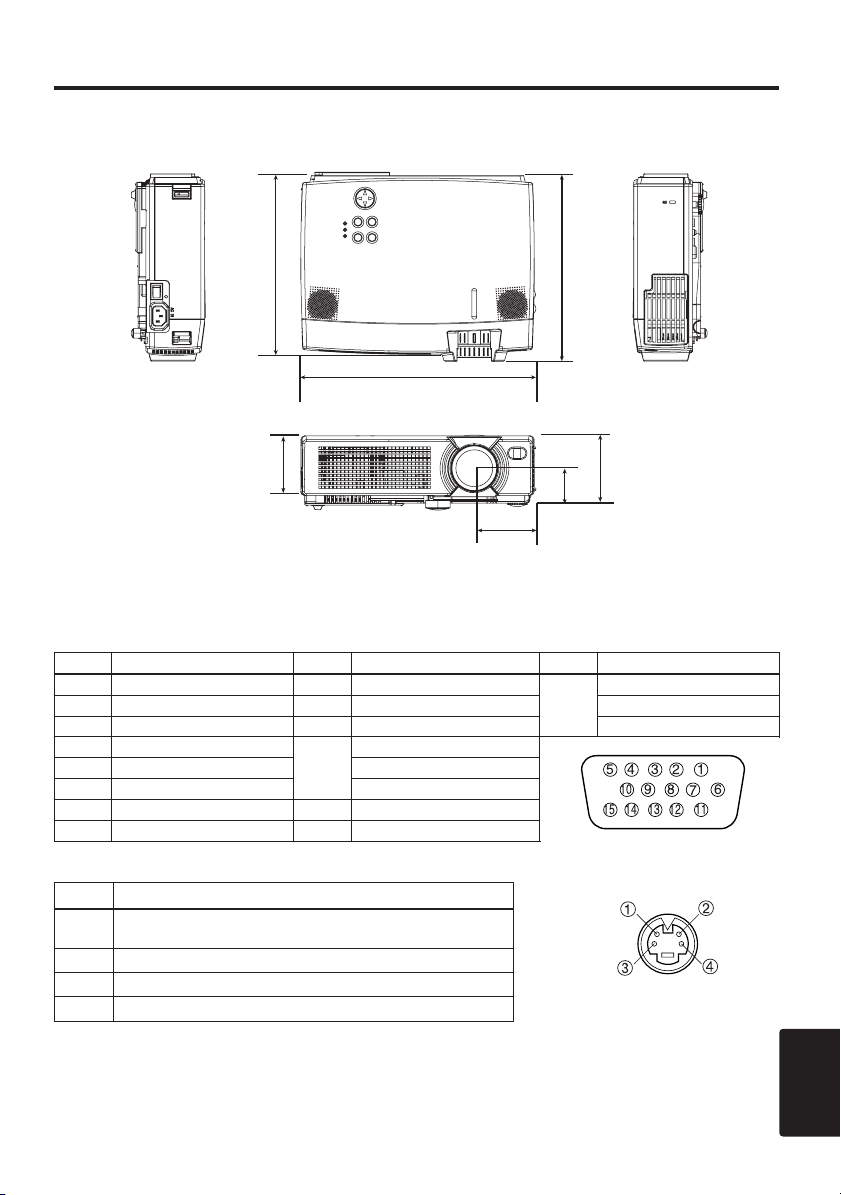
Dimension Diagram
228
241.5
298
76
94.6
54
76.5
Unit : mm
Signal Connector Pin Assignment
1. D-sub 15-pin Shrink Connector (RGB IN 1/RGB IN 2/RGB OUT)
Pin No Signal Pin No Signal Pin No Signal
1 Video input Red 9 -
2 Video input Green 10 Ground RGB IN 2: -
3 Video input Blue 11 - RGB OUT: -
4 -
5 Ground RGB IN 2: -
6 Ground Red RGB OUT: -
7 Ground Green 13
8 Ground Blue 14 Vertical sync
RGB IN 1: SDA(DDC)
12
H. sync./ Composite sync.
RGB IN 1: SCL(DDC)
15
2. Mini Din 4-pin Connector (S-VIDEO)
Pin No Signal
Color:0.286Vp-p (NTSC, burst signal),75Ω terminator
1
2 Brightness:1.0Vp-p, 75Ω terminator
3 Ground
4 Ground
0.3Vp-p (PAL/SECAM, burst signal),75Ω terminator
TECHNICAL
TECHNICAL - 1
Page 2

TTTTEEEECCCCHHHHNNNNIIIICCCCAAAALLLL((((ccccoooonnnnttttiiiinnnnuuuueeeedddd))
Example of computer signal
Resolution
H ××V
640 × 350
640 × 400
720 × 400
640 × 480
640 × 480
640 × 480
640 × 480
640 × 480
800 × 600
800 × 600
800 × 600
800 × 600
800 × 600
832 × 624
1024 × 768
1024 × 768
1024 × 768
1024 × 768
1152 × 864
1280 × 960
1280 × 1024
1280 × 1024
fH (kHz) fV (Hz) Rating Signal mode Display mode
37.9 85.1 VESA VGA-1 Zoom in
37.9 85.1 VESA VGA-2 Zoom in
37.9 85.0 VESA TEXT Zoom in
31.5 59.9 VESA VGA (60Hz) Zoom in
35.0 66.7 Mac13"mode Zoom in
37.9 72.8 VESA VGA (72Hz) Zoom in
37.5 75.0 VESA VGA (75Hz) Zoom in
43.3 85.0 VESA VGA (85Hz) Zoom in
35.2 56.3 VESA SVGA (56Hz)
37.9 60.3 VESA SVGA (60Hz)
48.1 72.2 VESA SVGA (72Hz)
46.9 75.0 VESA SVGA (75Hz)
53.7 85.1 VESA SVGA (85Hz)
49.7 74.5 Mac16"mode Zoom out
48.4 60.0 VESA XGA (60Hz) Zoom out
56.5 70.1 VESA XGA (70Hz) Zoom out
60.0 75.0 VESA XGA (75Hz) Zoom out
68.7 85.0 VESA XGA (85Hz) Zoom out
67.5 75.0 VESA SXGA (75Hz) Zoom out
60.0 60.0 VESA SXGA (60Hz) Zoom out
64.0 60.0 VESA SXGA (60Hz)
80.0 75.0 VESA SXGA (75Hz) Zoom out
))
Zoom out *
NOTE
• Some computers may have multiple display screen modes. Use of some of these modes
will not be possible with this projector.
• Be sure to check jack type, signal level, timing and resolution before connecting this projector to a
computer.
• Depending on the input signal, full-size display may not be possible in some cases. Refer to the
number of display pixels above.
• The image may not be displayed correctly when the input sync. signal is "Composite Sync." or
"Sync. on G".
* It becomes the simple display of thinning out data.
TECHNICAL - 2
Page 3
TTTTEEEECCCCHHHHNNNNIIIICCCCAAAALLLL((((ccccoooonnnnttttiiiinnnnuuuueeeedddd))
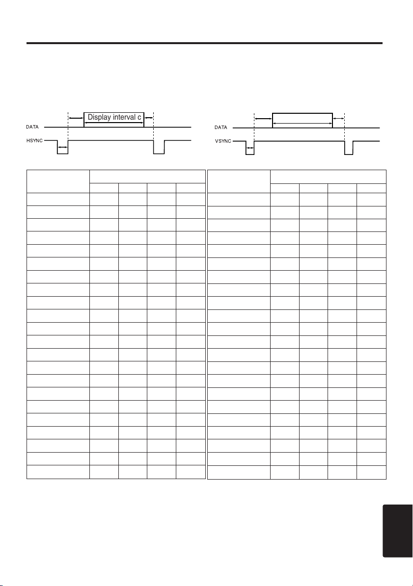
DATA
HSYNC
DATA
VSYNC
))
Initial set signals
The following signals are used for the initial settings.
The signal timing of some computer models may be different. In such case, refer to adjust the
V.POSIT and H.POSIT of the menu.
Back porch b
Display interval c
Front porch d
Back porch b
Front porch d
Display interval c
Sync a
Computer /
Signal
VGA-1 (85Hz) 2.0 3.0 20.3 1.0
VGA-2 (85Hz) 2.0 3.0 20.3 1.0
TEXT 2.0 3.0 20.3 1.0
VGA (60Hz) 3.8 1.9 25.4 0.6
Mac 13"mode 2.1 3.2 21.2 2.1
VGA (72Hz) 1.3 3.8 20.3 1.0
VGA (75Hz) 2.0 3.8 20.3 0.5
VGA (85Hz) 1.6 2.2 17.8 1.6
SVGA (56Hz) 2.0 3.6 22.2 0.7
SVGA (60Hz) 3.2 2.2 20.0 1.0
SVGA (72Hz) 2.4 1.3 16.0 1.1
SVGA (75Hz) 1.6 3.2 16.2 0.3
SVGA (85Hz) 1.1 2.7 14.2 0.6
Mac 16"mode 1.1 3.9 14.5 0.6
XGA (60Hz) 2.1 2.5 15.8 0.4
XGA (70Hz) 1.8 1.9 13.7 0.3
XGA (75Hz) 1.2 2.2 13.0 0.2
XGA (85Hz) 1.0 2.2 10.8 0.5
1152×864 (75Hz)
1280×960 (60Hz)
1280×1024 (60Hz)
1280×1024 (75Hz)
Horizontal signal timing (µs)
a b c d
1.2 2.4 10.7 0.6
1.0 2.9 11.9 0.9
1.0 2.3 11.9 0.4
1.1 1.8 9.5 0.1
Sync a
Computer /
Signal
VGA-1 (85Hz) 3 60 350 32
VGA-2 (85Hz) 3 41 400 1
TEXT 3 42 480 1
VGA (60Hz) 2 33 480 10
Mac 13"mode 3 39 480 3
VGA (72Hz) 3 28 480 9
VGA (75Hz) 3 16 480 1
VGA (85Hz) 3 25 480 1
SVGA (56Hz) 2 22 600 1
SVGA (60Hz) 4 23 600 1
SVGA (72Hz) 6 23 600 37
SVGA (75Hz) 3 21 600 1
SVGA (85Hz) 3 27 600 1
Mac 16"mode 3 39 624 1
XGA (60Hz) 6 29 768 3
XGA (70Hz) 6 29 768 3
XGA (75Hz) 3 28 768 1
XGA (85Hz) 3 36 768 1
1152×864 (75Hz)
1280×960 (60Hz)
1280×1024 (60Hz)
1280×1024 (75Hz)
Vertical signal timimg (lines)
a b c d
3 32 864 1
3 36 960 1
3 38 1024 1
3 38 1024 1
TECHNICAL
TECHNICAL - 3
Page 4
TTTTEEEECCCCHHHHNNNNIIIICCCCAAAALLLL((((ccccoooonnnnttttiiiinnnnuuuueeeedddd))
2
1
4
3
6
5
2
1
4
3
6
5
8
7
10
9
12
11
14
13
15
CLK
DATA
SEL0
RTS
GND
+5V
DATA
GND
+5V
CLK
2
1
4
3
6
5
1
2
3
4
5
678
9
10
11 12
13
14
15
))
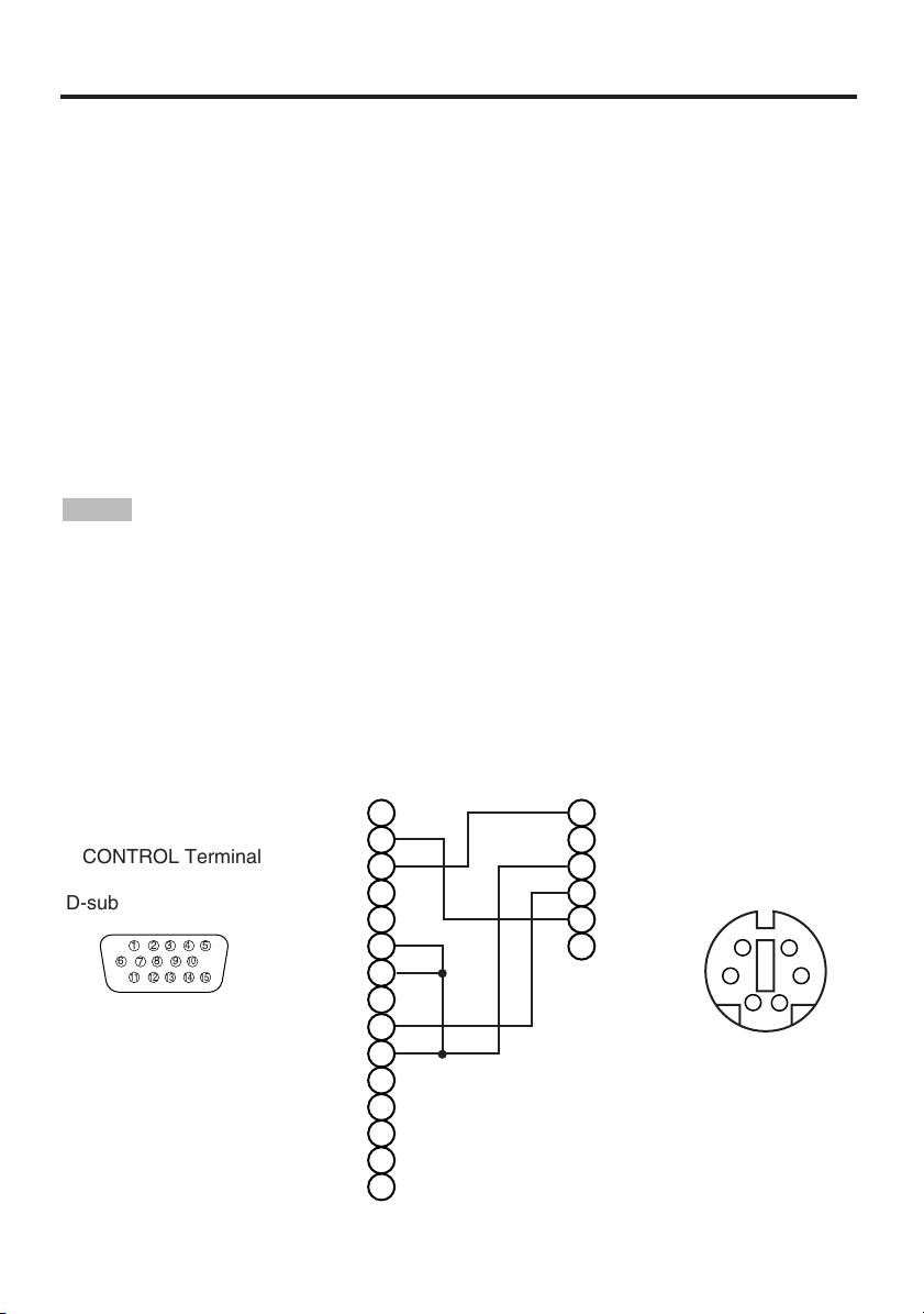
Connection to the Mouse Control
1. PS/2, ADB or Serial Mouse
(1) Turn off the projector and computer, and connect the two units with the appropriate cable. For
PS/2 mouse control (for IBM and compatible), use the enclosed mouse cable. For others, consult
your dealer.
(2) Disconnect the USB cable from the projector if it is connected. Then turn on the projector.
(3) Turn on the computer.
Start the mouse function. If the mouse has not been started, reboot the computer (soft reboot or
(4)
reboot buttons). Refer to the descriptions of “DISC PAD” and “MOUSE/RIGHT button” of page 4.
2. USB Mouse
(1) Connect the projector and computer with a suitable commercially available USB cable. Consult
your dealer to get the cable, if you need.
(2) Start the mouse function. Refer to the descriptions of “DISC PAD” and “MOUSE/RIGHT
button” of page 4.
NOTE
• Before connecting, read the instruction manuals of the devices to be connected.
• In the case of notebook type computers with an internal pointing device, the mouse control
function will not work unless the internal pointing device is disabled. In such case, disable the
internal pointing device and change the BIOS setting to select an external mouse before the
operations described in (1) to (4) above.
Also, some computers may not have a utility program to operate a mouse.
Refer to the computer hardware manual for detail.
PS/2 Mouse
CONTROL Terminal
D-sub 15-pin shrink jack
Projector
Computer
TECHNICAL - 4
Mouse jack
Mini DIN 6-pin
Page 5
TTTTEEEECCCCHHHHNNNNIIIICCCCAAAALLLL((((ccccoooonnnnttttiiiinnnnuuuueeeedddd))
1
2
3
4
1
2
3
4
+
5V
—
DATA
+
DATA
GND
+
5V
—
DATA
+
DATA
GND
1
234
2
1
3
4
2
1
4
3
6
5
2
1
4
3
8
7
10
9
12
11
14
13
15
RTS
GND
+5V
ADB
GND
+5V
(
POWER ON
)
DATA
2
1
4
3
1
2
3
4
5
678
9
10
11 12 13
14
15
2
1
4
3
6
5
2
1
4
3
6
5
8
7
10
9
8
7
9
12
11
14
13
15
RI
CD
RD
TD
DTR
GND
DSR
CTS
RTS
RTS
GND
SEL0
TD
21
4
3
6
5
8
9
7
1
2
3
4
5
678
9
10
11 12 13
14
15
))
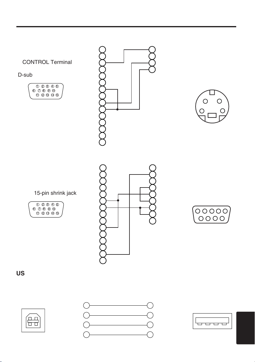
ADB Mouse
CONTROL Terminal
D-sub 15-pin shrink jack
Serial Mouse
CONTROL Terminal
D-sub 15-pin shrink jack
Projector
Projector
Computer
Mouse jack
Mini DIN 4-pin
Computer
Mouse jack
D-sub 9-pin
USB Mouse
USB jack
(B type)
Projector
USB cable
Computer
USB jack
(A type)
TECHNICAL - 5
TECHNICAL
Page 6

TTTTEEEECCCCHHHHNNNNIIIICCCCAAAALLLL((((ccccoooonnnnttttiiiinnnnuuuueeeedddd))
1
23
4
5
6
7
89
10
11
1213
1415
1
2
3
4
5
6
7
8
9
10
11
12
13
14
15
RD
TD
GND
SELO
RTS
1
2
3
4
5
6
7
8
9
CD
RD
TD
DTR
GND
DSR
RTS
DTS
RI
1
2345
67
8
9
))
RS-232C communication
(1) Turn off the projector and computer power supplies and connect with the RS-232C cable.
(2) Turn on the computer power supply and, after the computer has started up, turn on the projector
power supply.
Projector Computer
Control jack
D-sub 15-pin shrink jack
Communications setting
19200bps, 8N1
1 Protocol
Consist of header (7 bytes) + command data (6 bytes).
2 Header
BE + EF + 03 + 06 + 00 + CRC_low + CRC_high
CRC_low : Lower byte of CRC flag for command data.
CRC_high : Upper byte of CRC flag for command data.
3 Command data
Command data chart
byte_0 byte_1 byte_2 byte_3 byte_4 byte_5
Action Type Setting code
low high low high low high
RS-232C jack
D-sub 9-pin
TECHNICAL - 6
Action (byte_0 - 1)
Action Classification Content
1 SET Change setting to desired value.
2 GET Read projector internal setup value.
4 INCREMENT Increment setup value by 1.
5 DECREMENT Decrement setup value by 1.
6 EXECUTE Run a command.
Page 7

TTTTEEEECCCCHHHHNNNNIIIICCCCAAAALLLL((((ccccoooonnnnttttiiiinnnnuuuueeeedddd))
))
Requesting projector status (Get command)
(1) Send the request code Header + Command data (‘02H’+‘00H’+ type (2 bytes) +‘00H’+‘00H’)
from the computer to the projector.
(2) The projector returns the response code ‘1DH’+ data (2 bytes) to the computer.
Changing the projector settings (Set command)
(1) Send the setting code Header + Command data (‘01H’+‘00H’+ type (2 bytes) + setting code (2
bytes)) from the computer to the projector.
(2) The projector changes the setting based on the above setting code.
(3) The projector returns the response code ‘06H’ to the computer.
Using the projector default settings (Reset Command)
(1) The computer sends the default setting code Header + Command data (‘06H’+‘00H’+ type (2
bytes) +‘00H’+‘00H’) to the projector.
(2) The projector changes the specified setting to the default value.
(3) The projector returns the response code ‘06H’ to the computer.
Increasing the projector setting value (Increment command)
(1) The computer sends the increment code Header + Command data (‘04H’+‘00H’+ type (2 bytes)
+‘00H’+‘00H’) to the projector.
(2) The projector in creases the setting value on the above setting code.
(3) The projector returns the response code ‘06H’ to the computer.
Decreasing the projector setting value (Decrement command)
(1) The computer sends the decrement code Header + Command data (‘05H’+‘00H’+ type (2 bytes)
+‘00H’ + ‘00H’) to the projector.
(2) The projector decreases the setting value on the above setting code.
(3) The projector returns the response code ‘06H’ to the computer.
When a command sent by the projector cannot be understood by the computer
When the command sent by the projector cannot be understood, the error command ‘15H’ is
returned by the computer. Some times, the projector ignores RS-232C commands during other
works. If the error command ‘15H’ is returned, please send the same command again.
When data sent by the projector cannot be practice
When the command sent by the projector cannot be practiced, the the error code ‘1cH’ +‘xxxxH’ is
returned.
When the data length is greater than indicated by the data length code, the projector will ignore the
excess data code.
Conversely, when the data length is shorter than indicated by the data length code, an error code
will be returned to the projector.
NOTE
data.
Provide an interval of at least 40ms between the response code and any other code.
•
• The projector outputs test data when the power supply is switched ON, and when the lamp is lit.
Ignore this data.
• Commands are not accepted during warm-up.
• Operation cannot be guaranteed when the projector receives an undefined command or
TECHNICAL - 7
TECHNICAL
Page 8

TTTTEEEECCCCHHHHNNNNIIIICCCCAAAALLLL((((ccccoooonnnnttttiiiinnnnuuuueeeedddd))
Command data chart
Names Operation type Header
Red BE EF 03 06 00 3B D3 01 00 00 30 00 00
Orange BE EF 03 06 00 AB D2 01 00 00 30 01 00
Green BE EF 03 06 00 5B D2 01 00 00 30 02 00
Blank Color
Mirror
Freeze
Menu Color
Startup
Language
Set
Set
Set
Set
Set
Set
Blue BE EF 03 06 00 CB D3 01 00 00 30 03 00
Purple BE EF 03 06 00 FB D1 01 00 00 30 04 00
White BE EF 03 06 00 6B D0 01 00 00 30 05 00
Black BE EF 03 06 00 9B D0 01 00 00 30 06 00
Get BE EF 03 06 00 08 D3 02 00 00 30 00 00
Normal BE EF 03 06 00 C7 D2 01 00 01 30 00 00
H Inverse BE EF 03 06 00 57 D3 01 00 01 30 01 00
V lnverse BE EF 03 06 00 A7 D3 01 00 01 30 02 00
H&V Inverse BE EF 03 06 00 37 D2 01 00 01 30 03 00
Get BE EF 03 06 00 F4 D2 02 00 01 30 00 00
Normal BE EF 03 06 00 83 D2 01 00 02 30 00 00
Freeze BE EF 03 06 00 13 D3 01 00 02 30 01 00
Get BE EF 03 06 00 B0 D2 02 00 02 30 00 00
Red BE EF 03 06 00 7F D3 01 00 03 30 00 00
Orange BE EF 03 06 00 EF D2 01 00 03 30 01 00
Green BE EF 03 06 00 1F D2 01 00 03 30 02 00
Blue BE EF 03 06 00 8F D3 01 00 03 30 03 00
Purple BE EF 03 06 00 BF D1 01 00 03 30 04 00
Transparent BE EF 03 06 00 2F D0 01 00 03 30 05 00
Gray BE EF 03 06 00 DF D0 01 00 03 30 06 00
Get BE EF 03 06 00 4C D3 02 00 03 30 00 00
Turn ON BE EF 03 06 00 0B D2 01 00 04 30 00 00
Turn OFF BE EF 03 06 00 9B D3 01 00 04 30 01 00
Get BE EF 03 06 00 38 D2 02 00 04 30 00 00
English BE EF 03 06 00 F7 D3 01 00 05 30 00 00
Français BE EF 03 06 00 67 D2 01 00 05 30 01 00
Deutsch BE EF 03 06 00 97 D2 01 00 05 30 02 00
Español BE EF 03 06 00 07 D3 01 00 05 30 03 00
Italiano BE EF 03 06 00 37 D1 01 00 05 30 04 00
Norsk BE EF 03 06 00 A7 D0 01 00 05 30 05 00
Nederlands BE EF 03 06 00 57 D0 01 00 05 30 06 00
Português BE EF 03 06 00 C7 D1 01 00 05 30 07 00
Japanese BE EF 03 06 00 37 D4 01 00 05 30 08 00
Get BE EF 03 06 00 C4 D3 02 00 05 30 00 00
CRC Action Type Setting code
))
Command data
TECHNICAL - 8
Page 9

TTTTEEEECCCCHHHHNNNNIIIICCCCAAAALLLL((((ccccoooonnnnttttiiiinnnnuuuueeeedddd))
))
Command data chart
Names Operation type Header
Get BE EF 03 06 00 7C D2 02 00 07 30 00 00
Magnify
Auto off
Brightness Reset Execute BE EF 03 06 00 58 D3 06 00 00 70 00 00
Contrast Reset Execute BE EF 03 06 00 A4 D2 06 00 01 70 00 00
V.Position Reset Execute BE EF 03 06 00 E0 D2 06 00 02 70 00 00
H.Position Reset Execute BE EF 03 06 00 IC D3 06 00 03 70 00 00
H.Size Reset Execute BE EF 03 06 00 68 D2 06 00 04 70 00 00
Color Balance R Reset Execute BE EF 03 06 00 94 D3 06 00 05 70 00 00
Color Balance B Reset Execute BE EF 03 06 00 D0 D3 06 00 06 70 00 00
Sharpness Reset Execute BE EF 03 06 00 C4 D0 06 00 09 70 00 00
Color Reset Execute BE EF 03 06 00 80 D0 06 00 0A 70 00 00
Tint Reset Execute BE EF 03 06 00 7C D1 06 00 0B 70 00 00
Keystone_V Reset Execute BE EF 03 06 00 08 D0 06 00 0C 70 00 00
Auto Execute BE EF 03 06 00 91 D0 06 00 0A 20 00 00
Blank on/off
Error Status Get
Power
Input Source
Volume
Increment BE EF 03 06 00 1A D2 04 00 07 30 00 00
Decrement BE EF 03 06 00 CB D3 05 00 07 30 00 00
Get BE EF 03 06 00 08 86 02 00 10 31 00 00
Increment BE EF 03 06 00 6E 86 04 00 10 31 00 00
Decrement BE EF 03 06 00 BF 87 05 00 10 31 00 00
off BE EF 03 06 00 FB D8 01 00 20 30 00 00
Set
on BE EF 03 06 00 6B D9 01 00 20 30 01 00
Get BE EF 03 06 00 C8 D8 02 00 20 30 00 00
BE EF 03 06 00 D9 D8 02 00 20 60 00 00
(Example of Return)
00 00 01 00 02 00 03 00
(Normal) (Cover-error) (Fan-error) (Lamp-error)
04 00 05 00 06 00
(Temp-error) (Air flow-error) (Lamp-Time-over)
OFF
Set
ON
Get
RGB1 BE EF 03 06 00 FE D2 01 00 00 20 00 00
RGB2 BE EF 03 06 00 3E D0 01 00 00 20 04 00
Video BE EF 03 06 00 6E D3 01 00 00 20 01 00
Set
SVideo BE EF 03 06 00 9E D3 01 00 00 20 02 00
Component
Get BE EF 03 06 00 CD D2 02 00 00 20 00 00
Get BE EF 03 06 00 31 D3 02 00 01 20 00 00
Increment BE EF 03 06 00 57 D3 04 00 01 20 00 00
Decrement BE EF 03 06 00 86 D2 05 00 01 20 00 00
BE EF 03 06 00 2A D3 01 00 00 60 00 00
BE EF 03 06 00 BA D2 01 00 00 60 01 00
BE EF 03 06 00 19 D3 02 00 00 60 00 00
BE EF 03 06 00 AE D1 01 00 00 20 05 00
CRC Action Type Setting code
Command data
TECHNICAL - 9
TECHNICAL
Page 10

TTTTEEEECCCCHHHHNNNNIIIICCCCAAAALLLL((((ccccoooonnnnttttiiiinnnnuuuueeeedddd))
Command data chart
Names Operation type Header
Normal BE EF 03 06 00 46 D3 01 00 02 20 00 00
Mute
Brightness
Contrast
Color
Balance R
Color
Balance B
Keystone_V
Aspect
Display
Position at
16 : 9 or Small
V.Position
H.Position
H.Size
H.Phase
Set
Set
Set
Mute BE EF 03 06 00 D6 D2 01 00 02 20 01 00
Get BE EF 03 06 00 75 D3 02 00 02 20 00 00
Get BE EF 03 06 00 89 D2 02 00 03 20 00 00
Increment BE EF 03 06 00 EF D2 04 00 03 20 00 00
Decrement BE EF 03 06 00 3E D3 05 00 03 20 00 00
Get BE EF 03 06 00 FD D3 02 00 04 20 00 00
Increment BE EF 03 06 00 9B D3 04 00 04 20 00 00
Decrement BE EF 03 06 00 4A D2 05 00 04 20 00 00
Get BE EF 03 06 00 01 D2 02 00 05 20 00 00
Increment BE EF 03 06 00 67 D2 04 00 05 20 00 00
Decrement BE EF 03 06 00 B6 D3 05 00 05 20 00 00
Get BE EF 03 06 00 45 D2 02 00 06 20 00 00
Increment BE EF 03 06 00 23 D2 04 00 06 20 00 00
Decrement BE EF 03 06 00 F2 D3 05 00 06 20 00 00
Get BE EF 03 06 00 B9 D3 02 00 07 20 00 00
Increment BE EF 03 06 00 DF D3 04 00 07 20 00 00
Decrement BE EF 03 06 00 0E D2 05 00 07 20 00 00
4:3, Full BE EF 03 06 00 9E D0 01 00 08 20 00 00
16:9 BE EF 03 06 00 0E D1 01 00 08 20 01 00
Small BE EF 03 06 00 FE D1 01 00 08 20 02 00
Get BE EF 03 06 00 AD D0 02 00 08 20 00 00
Default BE EF 03 06 00 62 D1 01 00 09 20 00 00
Bottom BE EF 03 06 00 F2 D0 01 00 09 20 01 00
Top BE EF 03 06 00 02 D0 01 00 09 20 02 00
Get BE EF 03 06 00 51 D1 02 00 09 20 00 00
Get BE EF 03 06 00 0D 83 02 00 00 21 00 00
Increment BE EF 03 06 00 6B 83 04 00 00 21 00 00
Decrement BE EF 03 06 00 BA 82 05 00 00 21 00 00
Get BE EF 03 06 00 F1 82 02 00 01 21 00 00
Increment BE EF 03 06 00 97 82 04 00 01 21 00 00
Decrement BE EF 03 06 00 46 83 05 00 01 21 00 00
Get BE EF 03 06 00 B5 82 02 00 02 21 00 00
Increment BE EF 03 06 00 D3 82 04 00 02 21 00 00
Decrement BE EF 03 06 00 02 83 05 00 02 21 00 00
Get BE EF 03 06 00 49 83 02 00 03 21 00 00
Increment BE EF 03 06 00 2F 83 04 00 03 21 00 00
Decrement BE EF 03 06 00 FE 82 05 00 03 21 00 00
CRC Action Type Setting code
))
Command data
TECHNICAL - 10
Page 11

TTTTEEEECCCCHHHHNNNNIIIICCCCAAAALLLL((((ccccoooonnnnttttiiiinnnnuuuueeeedddd))
))
Command data chart
Names Operation type Header
Get BE EF 03 06 00 F1 72 02 00 01 22 00 00
Sharpness
Color
Tint
Video Format
HDTV
Increment BE EF 03 06 00 97 72 04 00 01 22 00 00
Decrement BE EF 03 06 00 46 73 05 00 01 22 00 00
Get BE EF 03 06 00 B5 72 02 00 02 22 00 00
Increment BE EF 03 06 00 D3 72 04 00 02 22 00 00
Decrement BE EF 03 06 00 02 73 05 00 02 22 00 00
Get BE EF 03 06 00 49 73 02 00 03 22 00 00
Increment BE EF 03 06 00 2F 73 04 00 03 22 00 00
Decrement BE EF 03 06 00 FE 72 05 00 03 22 00 00
Auto BE EF 03 06 00 9E 75 01 00 00 22 0A 00
NTSC BE EF 03 06 00 FE 71 01 00 00 22 04 00
PAL BE EF 03 06 00 6E 70 01 00 00 22 05 00
SECAM BE EF 03 06 00 6E 75 01 00 00 22 09 00
Set
NTSC 4.43 BE EF 03 06 00 5E 72 01 00 00 22 02 00
M-PAL BE EF 03 06 00 FE 74 01 00 00 22 08 00
N-PAL BE EF 03 06 00 0E 71 01 00 00 22 07 00
Get BE EF 03 06 00 0D 73 02 00 00 22 00 00
Set
1080i BE EF 03 06 00 F2 73 01 00 05 22 00 00
1035i BE EF 03 06 00 62 72 01 00 05 22 01 00
Get BE EF 03 06 00 C1 73 02 00 05 22 00 00
Command data
CRC Action Type Setting code
TECHNICAL - 11
TECHNICAL
Page 12

TTTTEEEECCCCHHHHNNNNIIIICCCCAAAALLLL((((ccccoooonnnnttttiiiinnnnuuuueeeedddd))
Command data chart
Names Operation type Header
off BE EF 03 06 00 CB D0 01 00 08 30 01 00
on BE EF 03 06 00 5B D1 01 00 08 30 00 00
Get BE EF 03 06 00 68 D1 02 00 08 30 00 00
NORMAL BE EF 03 06 00 3B 23 01 00 00 33 00 00
WHISPER BE EF 03 06 00 AB 22 01 00 00 33 01 00
Get BE EF 03 06 00 08 23 02 00 00 33 00 00
NORMAL BE EF 03 06 00 C7 F0 01 00 A1 30 00 00
CINEMA BE EF 03 06 00 57 F1 01 00 A1 30 01 00
DYNAMIC BE EF 03 06 00 A7 F1 01 00 A1 30 02 00
Get BE EF 03 06 00 F4 F0 02 00 A1 30 00 00
NORMAL BE EF 03 06 00 FB F5 01 00 B0 30 00 00
LOW BE EF 03 06 00 6B F4 01 00 B0 30 01 00
Get BE EF 03 06 00 C8 F5 02 00 B0 30 00 00
Sync on G
WHISPER
GAMMA
COLOR TEMP
Set
Set
Set
Set
))
Command data
CRC Action Type Setting code
TECHNICAL - 12
Page 13

REGULATORY NOTICES
REGULATORY NOTICES
FCC Statement Warning
WARNING: This equipment has been tested and found to comply with the
limits for a Class B digital device, pursuant to Part 15 of the FCC Rules. These
limits are designed to provide reasonable protection against harmful
interference in a residential installation. This equipment generates, uses, and
can radiate radio frequency energy and, if not installed and used in accordance
with the instructions, may cause harmful interference to radio communications.
However, there is no guarantee that interference will not occur in a particular
installation. If this equipment does cause harmful interference to radio or
television reception, which can be determined by turning the equipment off and
on, the user is encouraged to try to correct the interference by one or more of
the following measures:
- Reorient or relocate the receiving antenna.
- Increase the separation between the equipment and receiver.
- Connect the equipment into an outlet on a circuit different from that to which
the receiver is connected.
- Consult the dealer or an experienced radio/TV technician for help.
INSTRUCTIONS TO USERS: This equipment complies with the requirements
of FCC (Federal Communication Commission) equipment provided that the
following conditions are met.
The cables may have to be used with the core set to the projector side. Use
the cables which are included with the projector or specified.
Core
CAUTION: Changes or modifications not expressly approved by the party
responsible for compliance could void the user’s authority to operate the
equipment.
For the Customers in CANADA
NOTICE: This Class B digital apparatus complies with Canadian ICES-003.
Pour les utilisateurs au Canada
AVIS: Cet appareil numérique de la Classe B est conforme à la norme NMB-003 du
Canada.
REGULATORY NOTICES - 1
Page 14

 Loading...