

Page 1
b
m
a
n
Projector
IN
TE
R
INPUT
M
1
-
D
R
G
B
B
N
G
S-VIDEO
STANDBY
/
ON
T
E
M
P
VIDEO
C
O
M
P
O
NENT
LA
MP
KEYS
T
ON
E
S
E
ARCH
R
E
SE
T
ME
N
U
FOCUS
L
E
N
S SHI
F
T
ZO
O
M
CP-X1200/CP-X1250
CP-X1200/CP-X1250
User’’
User
Thank you for purchasing this projector.
store them in a safe place for future reference.
s Manual – Quick Guide
s Manual – Quick Guide
WARNING Before using, read the "User's Manual - Safety Guide" and
these manuals to ensure correct usage through understanding. After reading,
AMP
L
MP
E
T
N
O
/
Y
TANDB
S
O
E
D
VI
U
N
E
M
O
-VIDE
S
R
E
M
T
O
N
I
O
Z
FOCUS
T
T
N
SE
E
E
R
COMPON
G
BN
T
U
P
N
I
B
T
RCH
F
A
RG
E
S
SHI
S
N
LE
D
M1
E
N
O
T
S
Y
KE
NOTE
• The information in this manual is subject to change without notice.
• The manufacturer assumes no responsibility for any errors that may appear in this manual.
• The reproduction, transmission or use of this document or contents is not permitted without express
written authority.
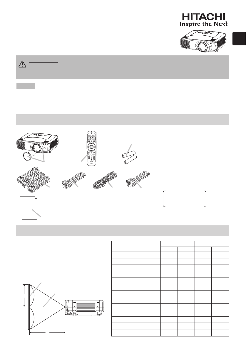
Contents Of Package
Contents Of Package
LASER INDICATOR
STANDBY/ON
VIDEO
1
6
+
LENS SHIFT
–––
BLANK
PREVIOUS
ESC MENU
POSITION
MAGNFY
ON
OFF
ID CHANGE
RGB
++
FOCUS ZOOM
ASPECT
LASER
NEXT
ENTER
RESET AUTO
PinP
VOLUME
FREEZE MUTE
KEYSTONE
SEARCH
1 2 3
7
1 Projector & Lens Cap
2
Power cords (UK, US, Europe)
3 RGB cable
4 Video/Audio cable
5 M1-D cable
6 Remote control
7 Batteries
(for the remote control)
23 4
5
8 User’s Manuals
Safety Guide
Quick Guide
Operating Guide
8
Arrangement
Arrangement
Refer to this table, in case of 4:3 aspect
ratios. The values a and b shown in the
table are calculated for a full size screen.
Screen
Lens center
Side view
Screen Size
[inch (m)]
40 (1.0) 46(1.2) 71(1.8) 12(30) 24(61)
60 (1.5) 71(1.8) 107(2.7) 18(46) 36(91)
70 (1.8) 83(2.1) 126(3.2) 21(53) 42(107)
80 (2.0) 95(2.4) 144(3.7) 24(61) 48(122)
100 (2.5) 120(3.0) 181(4.6) 30(76) 60(152)
120 (3.0) 144(3.7) 217(5.5) 36(91) 72(183)
150 (3.8) 181(4.6) 272(6.9) 45(114) 90(229)
200 (5.1) 243(6.2) 364(9.2) 60(152) 120(305)
250 (6.4) 304(7.7)
300 (7.6) 366(9.3)
350 (8.9)
400 (10.2)
500 (12.7)
a [inch (m)] b [inch (cm)]
Min. Max.
455(11.6)
547(13.9)
427(10.9) 638(16.2)
489(12.4) 730(18.5)
612(15.5) 913(23.2)
m:n=1:1 m:n=10:0
75(191) 150(381)
90(229) 180(457)
105(267) 210(533)
120(305) 240(610)
150(381) 300(762)
1
Page 2

Connecting Y
R/CR/PR G/Y B/CB/PB H V
Connecting Y
our Devices
our Devices
WARNING • Install the projector in a suitable environment according to
instructions of the “User’s Manual – Safety Guide”.
Please refer to the following for connecting your devices. See the rear of the projector. You can see
the ports.
Connecting to a computer
K
E
YST
O
N
E
L
E
N
M
S
1
S
D
H
IF
T
RG
B
S
I
E
N
P
AR
U
T
C
H
BN
G
C
OM
P
ON
E
N
T
RE
S
E
T
IN
S
T
V
E
R
ID
F
O
E
O
C
U
S
Z
O
O
M
V
ID
ME
EO
N
U
S
T
A
N
DBY
/
O
N
T
E
M
P
LA
M
A
U
D
I
O
I
N1
A
U
D
I
O
I
N
2
R
GB
RGB OUT
R/C
R
/P
R
G/Y
B/C
B
/P
B
H
BNC
P
REMOTE
CONTROL
C
O
NTROL
N
ETWORK
A
U
D
I
O
O
UT
CR/PR
C
a
/Pa
Y
V
R
A
U
D
IO
I
N
-L
V
ID
E
O
S-V
ID
E
O
Computer Projector
A
RGB out RGB cable RGB
Audio out Stereo Mini cable AUDIO IN 2
RS-232C port RS-232C cable CONTROL
Network port CAT-5 cable NETWORK
■ If using a M1-D input (to mouse control)
DVI port M1-D
USB port M1-D cable
Audio out Stereo Mini cable AUDIO IN 1
■ If using a BNC input
R/PR
R/C
G/Y
B/PB
B/C
RGB out
BNC cable
H
V
E
F
G
B
D
C
AUDIO IN1
E
A
AUDIO IN2
RGB
R/CR/PR G/Y B/CB/PB HV
BNC
B
D
AUDIO IN1
AUDIO IN2
RGB
G/Y H V
R/CR/PR B/CB/PB
BNC
D
AUDIO IN1
AUDIO IN2
RGB
R/C
R/PR G/Y B/CB/PB HV
C
BNC
RGB OUT
RGB OUT
RGB OUT
REMOTE CONTROL
AUDIO OUT
REMOTE CONTROL
AUDIO OUT
REMOTE CONTROL
AUDIO OUT
F G
NETWORK
CONTROL
CR/PR
Y
Ca/Pa
VIDEOR-AUDIO IN-L
S-VIDEO
CONTROL NETWORK
Y
CR/PR
Ca/Pa
VIDEOR-AUDIO IN-L
S-VIDEO
NETWORK
CONTROL
CR/PR
Y
Ca/Pa
VIDEOR-AUDIO IN-L
S-VIDEO
Audio out Stereo Mini cable AUDIO IN 1
2
D
Page 3

Connecting to a monitor
R-AUDIO IN-L VIDEO
R-AUDIO IN-L VIDEO
COMPONENT
R-AUDIO IN-L VIDEO
AUDIO IN1
AUDIO IN2
Monitor Projector
L
RGB in RGB cable RGB OUT
Connecting to a speaker (with amplifier)
AUDIO IN1
Speaker Projector
AUDIO IN2
M
Audio in Stereo Mini cable AUDIO OUT
Connecting to a VCR/DVD Player
VCR/DVD Player Projector
AUDIO IN1
Audio out (R)
Audio out (L)
Video out
R-AUDIO IN
AUDIO IN-L
VIDEO IN
H
I
AUDIO IN2
RGB
R/C
R/PR G/Y B/CB/PB HV
BNC
RGB
R/PR G/Y B/CB/PB HV
R/C
BNC
RGB
R/C
R/PR G/Y B/CB/PB HV
BNC
L
RGB OUT
RGB OUT
RGB OUT
REMOTE CONTROL
AUDIO OUT
REMOTE CONTROL
AUDIO OUT
M
REMOTE CONTROL
AUDIO OUT
CR/PR
Ca/Pa
CR/PR
Ca/Pa
CR/PR
Ca/Pa
H I
CONTROL
NETWORK
Y
VIDEOR-AUDIO IN-L
S-VIDEO
CONTROL
NETWORK
Y
VIDEOR-AUDIO IN-L
S-VIDEO
NETWORK
CONTROL
Y
VIDEOR-AUDIO IN-L
S-VIDEO
■ If using a s-video signal
S-video out S-video cable S -VIDEO
Audio out (R)
Audio out (L)
R-AUDIO IN
AUDIO IN-L
■ If using a component signal
CR/PR out
CB/PB out
Y out
Audio out (R)
Audio out (L)
CR/PR
CB/PB
Y
R-AUDIO IN
AUDIO IN-L
J
H
K
H
AUDIO IN1
AUDIO IN2
RGB
R/C
R/PR G/Y B/CB/PB HV
BNC
AUDIO IN1
AUDIO IN2
RGB
R/C
R/PR G/Y B/CB/PB HV
BNC
RGB OUT
RGB OUT
REMOTE CONTROL
AUDIO OUT
REMOTE CONTROL
AUDIO OUT
CONTROL
Y
CR/PR
Ca/Pa
H J
VIDEOR-AUDIO IN-L
CONTROL
K
CR/PR
Y
Ca/Pa
H
VIDEOR-AUDIO IN-L
NETWORK
S-VIDEO
NETWORK
S-VIDEO
3
Page 4

Connecting The Power Supply
I
N
T
E
R
I
N
P
U
T
M
1-
D
RG
B
B
NG
S-
V
I
D
E
O
S
T
AN
D
B
Y
/
ON
T
E
MP
VID
E
O
C
O
MP
O
N
E
N
T
LAMP
K
E
Y
S
T
O
N
E
SE
A
RCH
R
E
S
E
T
ME
N
U
F
O
CU
S
LE
N
S
S
H
IF
T
ZO
O
M
Connecting The Power Supply
WARNING •
Use extra caution when connecting the power cord as incorrect or faulty
connections may result in fire and/or electrical shock. Please adhere to the “User’s manual –
Safety Guide” and the following.
•
Only plug the power cord into outlets rated for use with the power cord’s specified voltage range.
•
Only use the power cord that came with the projector. If it is damaged, contact your dealer to
newly get correct one.
•
Never modify the power cord. Never attempt to defeat the ground connection of the three-pronged plug.
•
Make sure that you firmly connect the power cord to the projector and wall outlet.
Connect the connector of the power cord to
1
the AC inlet of the projector.
Firmly plug the power cord’s plug into the
2
outlet.
A
U
D
IO
I
N1
A
UDIO
I
N2
R/C
R
/P
R
G/Y
REMOTE
RGB
R
GB OU
T
B
/C
B
/P
B
H
V
BNC
AC Inlet
K
E
Y
S
T
O
N
E
L
E
N
M1
S
SH
-
D
I
F
T
RGB
SE
I
N
P
A
U
R
T
C
H
BN
G
COMP
ONE
N
T
R
E
SE
T
I
N
S-
T
V
E
R
I
D
F
OC
E
O
U
S
Z
OO
V
ID
C
O
NTROL
CONTROL
A
UDIO
O
U
T
CR/PR
Ca/Pa
Y
R-A
U
DIO IN-L
VIDE
O
M
M
E
O
E
N
U
S
T
AND
B
Y
/
ON
TEM
P
LA
M
P
NETWORK
S-VID
EO
Outlet
Connector Plug
Adjusting The Projector's Elevator
Adjusting The Projector's Elevator
WARNING • Do not touch about the lens and ventilation openings during use or
immediately after use to prevent a burn.
CAUTION
• To prevent damaging the projector and injuring yourself, always
hold the projector whenever using the elevator buttons to adjust the elevator feet.
Press and hold in the elevator buttons.
1
Elevator buttons
Raise or lower the projector to the desired height and
2
then release the elevator buttons.
When you release the elevator buttons, the elevator
feet will lock into position.
As necessary, you can also finely adjust the height of
3
the projector by twisting the elevator feet by hand.
Elevator feet
4
Page 5

Preparing Remote Control
STANDBY/ON
VIDEO
LASER
INDICA
TO
R
ESC
MENU
POSITION
RESET AUTO
KEYSTONE
1 2 3
ID CHANGE
SEARCH
ON
OFF
FREEZE MUTE
MAGNFY
PinP
VOLUME
RGB
BLANK
PREVIOUS
NEXT
ASPECT
ENTER
LASER
LENS SHIFT
+
–––
++
FOCUS
ZOOM
AVOID EXPOSURE-LASER
RADIATION IS EMITTED
FROM THIS APERTURE
CAUTION
WAVE LENGTH: 640-660nm
MAX OUTPUT: 1mW
CLASS 2 LASER PRODUCT
Comples with 21 CFR, 1040.10 AND 1040.11
IEO60825-1:1993+A1:1997+A2:2001
LASER-STRAHLING
NICHT IN DEN STRAHL BLICKEN
LASER KLASSE 2
WAVE LENGTH:640-660nm MAX OUTPUT:1mW
レーザー光
ビームをのぞきこまないこと
クラス2レーザー製品 JISC6802(1998)
最大出力:1.0mW 波長:640−660nm
MODEL:H-IRC4
LASER RADIATION
DO NOT STARE INTO BEAM
MANUFACTURER: B
MANUFACTURED
JANUARY,2003
INTERLINK K.K.
1-10-7 HIGASHIKANDA CHIYODA-KU,TOKYO,JAPAN
101-0031
MADE IN CHINA
JQA
MADE IN CHINA
P S
C
レーザー光をのぞき込まないこと。
レーザー光を人に向けないこと。
子供に使わせないこと。
製造者:INTERLINK ELECTRONICS
Preparing Remote Control
WARNING • The laser pointer of the remote control is used in place of a finger or
rod. Never look directly into the laser beam outlet or point the laser beam at other
people. The laser beam can cause vision problems.
CAUTION
• Use of controls or adjustments or performance of procedures other
than those specified herein may result in hazardous radiation exposure.
CAUTION • About the battery
• Keep a battery away from children and pets.
• Use only the battery specified: two AA batteries.
• Do not mix new battery with used one.
• Make sure the plus and minus terminals are correctly aligned when loading the
battery (as indicated in the remote control).
• Dispose of batteries in accord with environmental laws.
Remove the battery cover.
1
Slide back and remove the battery cover in the direction of
the arrow.
2
3
Insert the batteries.
Align and insert the two AA batteries according to their plus
minus terminals (as indicated in the remote control).
Close the battery cover.
Replace the battery cover in the direction of the arrow and
snap it back into place.
5
 Loading...