

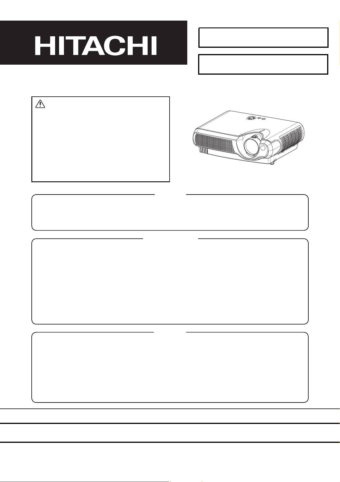
Hitachi CP-S235W Service Manual
SM0541
CP-S235W(C10SM2)
SERVICE MANUAL
Warning
The technical information and parts shown in this
manual are not to be used for the development,
design, production, storage or use of nuclear, chemical,
biological or missile weapons or other weapons of
mass destruction; or military purposes; or purposes that
endanger global safety and peace. Moreover, do not
sell, give or export these items or grant permission for
use to parties with such objectives. Forward all inquiries
to Hitachi Ltd.
Caution
Be sure to read this manual before servicing. To assure safety from fi re, electric shock, injury, harmful radi-
ation and materials, various measures are provided in this Hitachi Multimedia LCD Projector. Be sure to
read cautionary items described in the manual to maintain safety before servicing.
Service Warning
1. When replacing the lamp, avoid burns to your fi ngers. The lamp becomes very hot.
2. Never touch the lamp bulb with a fi nger or anything else. Never drop it or give it a shock. This may
cause bursting of the bulb.
3. This projector is provided with a high voltage circuit for the lamp. Do not touch the electric parts of
power unit (main) when the projector is turned on.
4. Do not touch the exhaust fan during operation.
5. The LCD module assembly is easily damaged. When replacing the LCD LENS/PRISM assembly, do
not hold the FPC of the LCD module assembly.
6. Use only the cables included with the projector or specified.
Contents
1. Features --------------------------------------------------- 2
2. Specifi cations --------------------------------------------- 2
3. Part names ------------------------------------------------ 3
4. Adjustment ----------------------------------------------- 5
5. Troubleshooting ----------------------------------------11
6. Service notes -------------------------------------------- 16
7. Wiring diagram ----------------------------------------- 30
8. Assembly diagram-------------------------------------- 35
9. Replacement parts list ------------------------------- 38
10.RS-232C communication --------------------------- 39
11.Block diagram ------------------------------------------ 47
12.Connector connection diagram ----------------- 48
13.Basic circuit diagrams -------------------------------- 49
SPECIFICATIONS AND PARTS ARE SUBJECT TO CHANGE FOR IMPROVEMENT.
Multimedia LCD Projector
March 2004 Digital Media Division
1. Features
Ultra high brightness
Whisper mode equipped
User memory function
Partial magnification function
Keystone distortion correction
2. Specifications
CP-S235 (C10SM2)
Liquid
Crystal
Panel
Video Input System NTSC, PAL (BGDHI), SECAM, PAL-M, PAL-N, NTSC4.43, PAL60
RGB input /
output
Drive system TFT active matrix
Panel size 1.4cm (0.55type)
Number of pixels 800 (H) × 600 (V)
Lamp 160W UHB
Level Composite 1.0 ±0.1Vp-p (75Ω termination)
S-Video Y : 1.0 ±0.1Vp-p (75Ω termination)
C : 0.286 ±0.1Vp-p (NTSC burst signal,75Ω termination)
0.3 ±0.1Vp-p
Component Y: 1.0 ±0.1Vp-p (75Ω termination)
C
C
Analog RGB 0.7Vp-p (75Ω termination)
Sync. TTL level
Audio Input 200mVrms, 50KΩ
Speaker output 1.0W (mono)
Power supply 100~120VAC / 2.6A, 220~240VAC / 1.4A
Power consumption 240W
Dimensions 332(W) × 92(H) × 254(D) mm (No including protruding parts)
Weight 3.0Kg
Temperature Operation : 0~35°C Storage : -20~60°C
Accessories Remote control transmitter × 1
RGB cable × 1
(Power cord)
Strap for lens cap × 1
Rivet for lens cap × 1
: 0.7 ±0.1Vp-p (75Ω termination)
B/PB
: 0.7 ±0.1Vp-p (75Ω termination)
R/PR
(PAL/SECAM burst signal,75Ω termination)
Battery × 2
Soft case × 1
User's manual operating guide (Book × 2 or CD-ROM × 1)
User's manual quick guide (Book× 1)
User's manual safety guide (Book× 1)
2
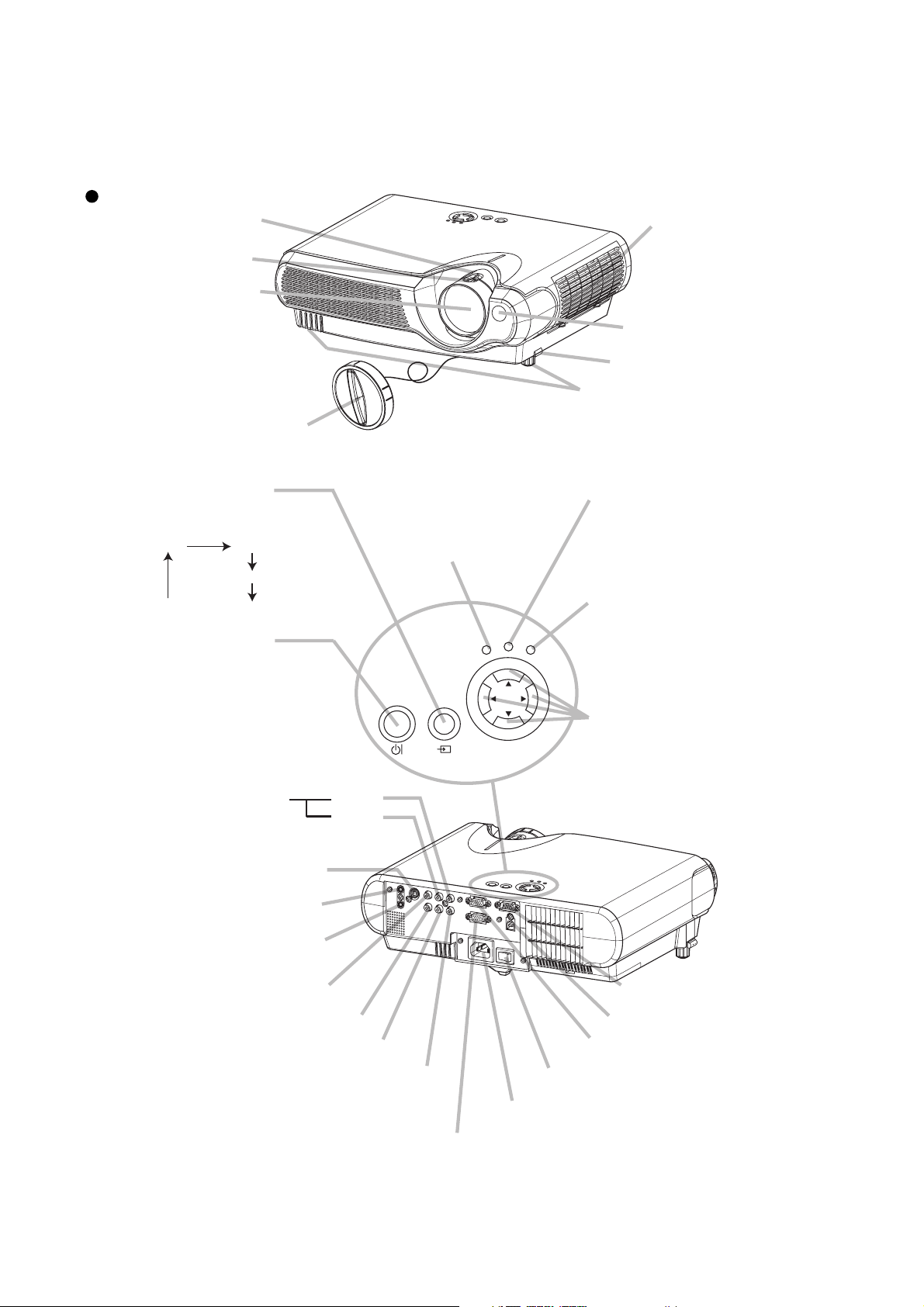
3. Part names
Projector
Zoom ring
Focus ring
Lens
(The picture is
projected from
here.)
CP-S235 (C10SM2)
Air filter cover
(An air filter is
inside.)
Remote sensor
Elevator button
Elevator feet
Lens cap
Projector (Front/Right)
INPUT button
toggles between the signal
ports.
RGB VIDEO
S-VIDEO
COMPONENT VIDEO
STANDBY/ON
button
prepares for turning the
power on/off. Refer to the
section “Power ON/OFF”.
AUDIO R port
(from a video equipment)
S-VIDEO port
AUDIO OUT port
AUDIO IN port
(from a computer)
VIDEO port
POWER indicator
tells the state of power
supply. Refer to the section
“Power ON/OFF”.
POWER
STANDBY/ON
INPUT
L port
TEMP indicator
lights or blinks when any
problem about internal
temperature has happened.
LAMP indicator
lights or blinks when any
TEMP
LAMP
MENU
problem about the lamp has
happened.
MENU buttons
operate the menu function.
AC
IN
RGB OUT port
COMPONENT VIDEO - Y
COMPONENT VIDEO - CB/PB
COMPONENT VIDEO - CR/PR
USB port
RGB IN port
Power switch
AC inlet
CONTROL port
Projector (Rear/Left)
3
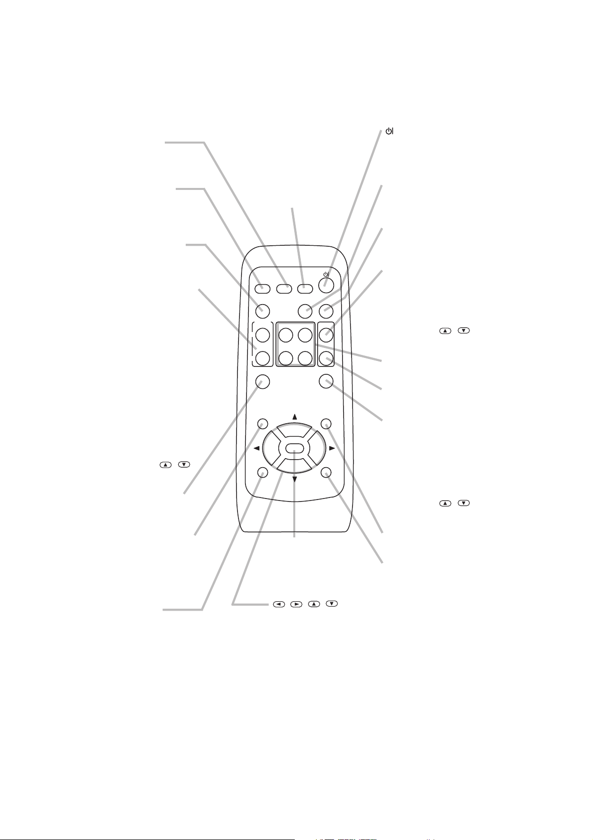
RGB button
selects the input signal of
RGB port.
VIDEO button
toggles between the signal
ports of VIDEO, S-VIDEO
and COMPONENT VIDEO.
ASPECT button
toggles between the
modes for aspect ratio.
MAGNIFY ON/OFF
buttons
turns on/off the MAGNIFY
mode.
In the MAGNIFY mode,
To move the
magnified area,
(1) Press the POSITION
button.
(2) Use the cursor buttons
to move the picture.
(3) Press the POSITION
button again to finish.
To shift the magnify
level,
use the cursor
/
buttons.
FREEZE button
freezes/reactivates the
picture.
POSITION button
turns on/off the POSITION
mode. (for RGB input)
In the POSITION mode,
To move the picture,
use the cursor buttons.
ESC button
returns to the previous display
at the menu functions.
(Available for
operating PC screen)
CP-S235 (C10SM2)
SEARCH button
searches for an input
signal between the
following signal ports of
RGB, VIDEO, S-VIDEO
and COMPONENT VIDEO.
RGB
VIDEO
ASPECT
MAGNIFY
ON
OFF
ESC RESET
proceeds to the next operation
at the menu functions.
(Available for
operating PC screen)
works for adjusting or
menu controlling.
(Available for
SEARCH
AUTO BLANK
PAGE DOWN
VOLUME
MUTE
KEYSTONEFREEZE
MENUPOSITION
HOME PAGE UP
END
ENTER
ENTER button
,,,
(Cursor) buttons
operating PC screen)
(STANDBY/ON)
button
prepares for turning the
power on/off.
AUTO button
executes automatic
adjustment.
BLANK button
blanks the screen
temporarily.
VOLUME button
turns on/off the VOLUME
mode.
In the VOLUME mode,
To adjust the volume,
use the cursor
/
buttons.
KEYBOARD button
operate the PC screen.
MUTE button
mutes/restores the sound.
KEYSTONE
button
turns on/off the KEYSTONE
mode.
In the KEYSTONE mode,
To adjust the
keystone,
use the cursor
/
buttons.
MENU button
opens/closes the menu.
RESET button
cancels the adjustment in
progress.
* The adjustments of the
volume etc. are not reset.
Remote control transmitter
4
CP-S235 (C10SM2)
4. Adjustment
4-1 Before adjusting
4-1-1 Selection of adjustment
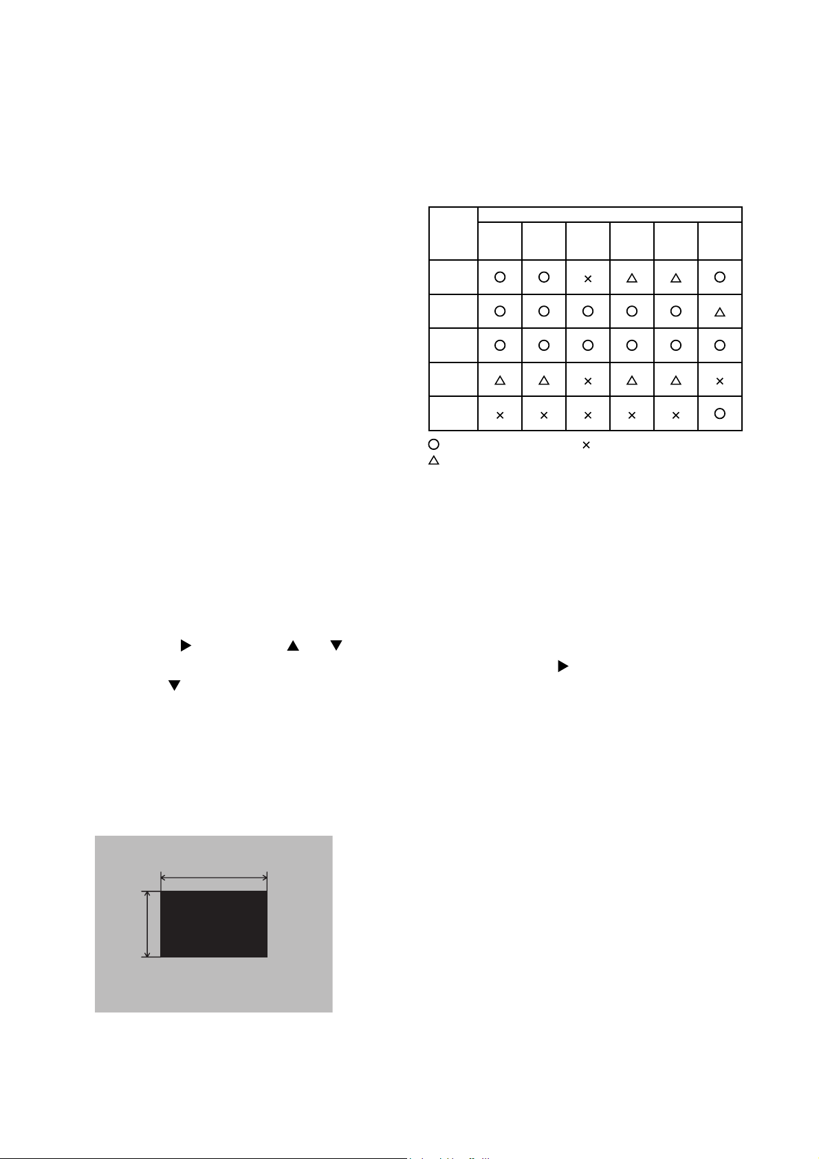
When any parts in the table 4-1 are changed, choose
the proper adjusting items with the chart.
4-1-2 Setting of condition before adjustment
1. Before starting adjustment, warm up the projector
for about 10 minutes. (Blank white)
2. Set Zoom Wide to Max. And project an image
with more than 1m (40 type) in diagonal size.
3. Normalising the video adjustment.
(Press the [MENU] button of the Remote control
transmitter to display the MAIN menu. After
pressing the [
select [RESET]. Next, open MAIN menu and
press the [
menu. Choose RESET and perfom EXECUTE by
the same operation described above.
*note :The MAIN and PICTURE1 menu is not
reset with no signal.
] key, use the [ ] or [ ] key to
] key to display the PICTURE1
Table 4-1: Relation between the replaced part and adjustment
Replaced
part
Dichroic
optics unit
LCD/LENS
prism
assembly
Main
Board
Lamp
unit
assembly
Sensor
Board
Ghost
(Chap.4-2)
Flicker
(Chap.4-3)
: means need for adjustment.
: means recommended.
Adjustment
NRSH
(Chap.4-4)
White
balance
(Chap.4-5)
: means not need for adjustment.
Colour
uniformity
(Chap.4-6)
AIR
SENSOR
(Chap.4-7)
4. Set the NORMAL at GAMMA in the PICTURE1
menu.
Perform all adjustments from the FACTORY MENU.
5.
Perform the following operations to display the
FACTORY MENU.
a.
Press the [MENU] button on the Remote control
transmitter (the MAIN menu will appear).
b. Select the [RESET] in the MAIN menu, and
then press the [ ] button.
c. Next, press the [RESET] button one time. And
hold the [RESET] button for 3 seconds or
more (the
FACTORY MENU
will appear).
4-2 Ghost adjustment
Signals for internal adjustment
30%
30%
0/255
112/255
Adjustment procedure
1.
Use DAC-P - GHOST - R: in the FACTORY MENU
to adjust so that R colour ghost is at a minimum.
(Set the adjustment value to default, and then
raise the value. When a ghost appears to the left
of a vertical line, reduce the value by 4 steps.)
2. In the same way, use DAC-P - GHOST-G: in the
FACTORY MENU to adjust so that G colour ghost
is at a minimum.
3. In the same way, use DAC-P - GHOST-B: in the
FACTORY MENU to adjust so that B colour ghost
is at a minimum.
5

CP-S235 (C10SM2)
4-3 Flicker adjustment
(V.COM adjustment)
Signals for internal adjustment
4-4
NRSH adjustment (vertical stripe adjustment)
Signals for internal adjustment
160
/255
136
/255
112
/255
64/255
88/255
112/255
136/255
88
/255
64
/255
Adjustment procedure
1. Make this adjustment after completing the
adjustment in 4-2 Ghost adjustment.
2. Use DAC-P - V.COM - R: in the FACTORY MENU
to adjust so that the flicker at the centre of the
screen is less than the flicker at the periphery.
(When the flicker is about the same across the
whole screen, adjust so that the flicker at the centre
of the screen is somewhat less than elsewhere.)
3. In the same way, use DAC-P - V.COM-G: in the
FACTORY MENU to adjust the G colour flicker.
4. In the same way, use DAC-P - V.COM-B: in the
FACTORY MENU to adjust the B colour flicker.
Adjustment procedure
1. Either of adjustment patterns as shown on the left
appears, which depends on the firmware version.
If any other pattern is displayed, press the
[ENTER] key on the remote control.
2.
Use the DAC-P - NRSH - R: in the FACTORY MENU to
adjust so that the vertical stripes with one pixel width
every 6 pixels are as inconspicuous as possible.
(Note that when the adjustment value is lowered, stripes
with 6 pixels width every 12 pixels may appear on the
right side of the darkest or the 2nd darkest tone. Should
this happen, make as inconspicuous stripes as possible
on the whole screen.)
3.
In the same way, use DAC-P - NRSH - G: in the
FACTORY MENU to adjust vertical stripes of G colour.
160/255
4-5
White balance adjustment
(visual inspection)
Preparations
1. Perform these adjustments after the NRSH
adjustment described in Section 4-4.
Adjustment procedure
1. First, adjust the G colour.
Select GAMMA, SUB-CNT, and G: in the FACTORY
2.
MENU. If the background is white solid, press the
[ENTER] key on the Remote control transmitter to
change to [G] monochrome in the 29-tone greyscale.
3.
Adjust GAMMA, SUB-CNT, and G: in the FACTORY
MENU so that brightness of 29 steps is best.
4. Don’t adjust GAMMA, SUB-BRT, and G: in the
FACTORY MENU. Because we want to keep the
best contrast ratio.
5. Then adjust colours R and B.
2. Reset gamma correction before adjustment.
Place the cursor on [GAMMA] in the FACTORY
MENU, press the [RESET] key and select [DEFAULT].
Select GAMMA, SUB-CNT, and G: in the FACTORY
6.
MENU. If the background is white solid, press the
[ENTER] key on the Remote control trasmitter to
change to [W] monochrome in the 29-tone greyscale.
7. Adjust GAMMA, SUB-BRT, R: and B: in the
FACTORY MENU so that low-brigtness white
balance is best.
8.
Adjust GAMMA, SUB-CNT, R: and B: in the FACTORY
MENU so that middle-brightness white balance is best.
9. Repeat steps 7 to 8 above, and adjust so that
brightness white balance of 29 steps is best.
6
CP-S235 (C10SM2)
4-6 Colour uniformity adjustment
Preparations
1. Perform these adjustments after the white
balance adjustment described in Section 4-5.
2. Make a colour uniformity adjustment for the
following four tones.
MIN tone (approx. 3% input signal)
MID-L tone (approx. 13% input signal)
MID-H tone (approx. 22% input signal)
MAX tone (approx. 50% input signal)
3. Place the cursor on [C.UNIF.] in the FACTORY
MENU and press the [ ] key. This displays the
Adjust Tone menu at the bottom of the screen.
To choose the tone to be adjusted, press the [
key and then use the [ ] or [ ] key.
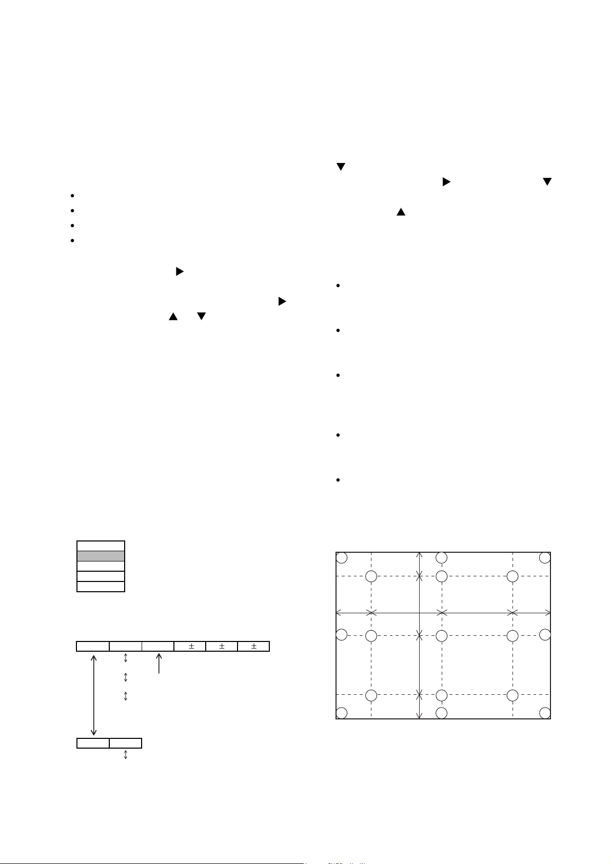
Select the major adjustment lattice point No. and
color, and then adjust them.
4. The major adjustment lattice point numbers (a
total of 17 points) corresponds to the major
adjustment lattice point positions in the diagram
on the right. The colour uniformity of the entire
screen can be adjusted by adjusting the white
balance for each of the points starting in order
from the low numbers.
5. Adjustment point No.1 should not be adjusted,
because it controls the brightness of the entire
screen.
]
6. To temporarily turn correction off, place the cursor
on [C.UNIF.] in the Adjust Tone menu and press the
] key. The ON/OFF menu appears. Place the
[
cursor on [ON] with the [ ] key and press the [ ]
key. To turn it on again, place the cursor on [OFF]
and press the [
] key.
7. Although this adjustment can also be made using
internal signals, we will here use the [ENTER] key
on the Remote control transmitter to select the
following two signals.
Solid monochrome adjustment colour (use G
colour adjustment when a colour differential meter
is used).
Solid white (use for adjustment other than
above).
8. Reset colour-shading correction before adjustment.
When 4 tones and all colours are to be reset,
place the cursor on [C.UNIF.] in the FACTORY
MENU, press the [RESET] key and select
[DEFAULT].
When only 1 tone is to be reset, place the
cursor on the tone to be reset, press the
[RESET] key and select [DEFAULT].
Single tone and monochrome resets cannot be
performed.
FACTORY MENU
VID-AD
C. UNIF.
DAC-P
GAMMA
STRIPE
Adjust tone menu
C.UNIF
ON/OFF ON
MIN
MID-L
MID-H
MAX
OFF
No. 1 R 0
Major adjustment lattice point No.
G0 B0
Major adjustment lattice point position
14 12
6 4 8
H/6 H/3 H/3 H/6
10 11
15 17
2 1 3
7 5 9
V/6
V/3
V/3
V/6
13
7
16

CP-S235 (C10SM2)
Adjustment procedure 1
(when a colour differential meter is used)
1. First adjust [MID-L] tone [G:].
2. Select adjustment point [No.2][G:].
When the background is not [G] monochrome,
press the [ENTER] key on the Remote control
transmitter to change to solid [G] monochrome.
3. Measure the illumination at adjustment points No.
2, No.3, No.10 and No.11.
The values should be:
No.2 = Y2 [lx] No.10 = Y10 [lx]
No.3 = Y3 [lx] No.11 = Y11 [lx]
4. No.2 and No.3 adjustment point have the average
of Y2 and Y3.
Y2 = ( Y2 + Y3 ) / 2 ±2 [%]
Y3 = ( Y2 + Y3 ) / 2 ±2 [%]
5. No.10 and No.11 adjustment point have the
average of Y10 and Y11.
Y10 = ( Y10 + Y11 ) / 2 ±2 [%]
Y11 = ( Y10 + Y11 ) / 2 ±2 [%]
6. Then adjust [MID-L] tone [R] and [B].
When the background is [G] monochrome, press
the [ENTER] key on the Remote control
transmitter to change to solid white.
7. Measure the colour co-ordinates of adjustment
point [No.1] and make a note of them.
Assume that they are x = x1, y = y1.
Note: When the CL-100 colour and colour
difference meter is used, the [
mode is convenient. When adjustment
point [No.1] colour co-ordinate has been
selected, set the slide switch on the side to
[
](delta) while holding down the [F] button
on the front panel. The measurement
shown after this displays the deviation from
measurement point 1.
8. Measure the colour co-ordinates of measurement
point [No.2] and adjust [No.2][R:] and [B:] so that
the co-ordinates are as follows.
x = x1 ± 0.005 , y = y1 ± 0.010
](delta)
9. Similarly, measure adjustment points [No.3] to
[No.17] and adjust their colour co-ordinates starting
in order from the small number points.
This completes adjustments required for [MIN].
Note: Since excessive correction may lead to a
correction data overview during internal
calculations, use the following values for
reference.
[No.2] to [No.5] ±40 or less
[No.6] to [No.9] ±50 or less
[No.10] to [No.13] ±70 or less
[No.14] to [No.17] ±120 or less
10. Then adjust [MIN] tone [G] so that the adjustment
data set two times as much as [MID-L] tone [G].
This completes [G] colour adjustments.
11. Then adjust [MIN] tone [R] and [B].
Select [No.2] [B:] and press the [ENTER] key on
the Remote control transmitter to change to solid
white.
12. Measure the colour co-ordinates of adjustment
point [No.1] and make a note of them.
Assume that they are x = x1, y = y1.
13. Now measure the colour co-ordinates of
measurement point [No.2] and adjust [No.2][R:]
and [B:] so that the co-ordinates are as follows.
x = x1 ±0.005 , y = y1 ±0.010 (Target)
x = x1 ±0.020 , y = y1 ±0.040
14. Similarly, measure adjustment points [No.3] to
[No.17] and adjust their colour co-ordinates starting
in order from the small number points.
This completes [MIN] tone adjustments.
15. Now make similar adjustments for [MID-H] tone.
(Adjust [MID-H] tone [G] so that the adjustment
data set half as many as [MID-L] tone [G].)
16. Now make similar adjustments for [MAX] tone.
(Adjust [MAX] tone [G] so that the adjustment
data set half as many as [MID-L] tone [G].)
8
CP-S235 (C10SM2)
Adjustment procedure 2
(visual inspection)
1. First adjust [MIN] tone [G:].
2. Select [No.2] [G:].
If the background is [G] monochrome, press the
[ENTER] key on the Remote control transmitter to
change to solid white.
3. View measurement point [No.2] and [No.3].
Lower the [G] colour intensity only of the colour
point whose [G] colour is more intense than
measurement point [No.1].
4. View measurement point [No.10] and [No.11].
Lower the [G] colour intensity only of the colour
point whose [G] colour is more intense than
measurement point [No.1], and raise the intensity
of the point whose colour intensity is lower than
measurement point [No.1].
5. Now adjust the [MIN] tone for colours [R] and [B].
6. View measurement points [No.2], [No.3], [No.10]
and [No.11]. Adjust the [R] and [B] of each
measurement point so that they have the same
color as measurement point [No.1].
Adjustment technique:
First, adjust [B:] of the point whose colour is to be
adjusted so that it approximates that of [No.1]. If
[R:] is low at this time, the image will have cyan
cast, in which case [R:] is increased. On the other
hand, if [R:] is excessive, the image will have a
magenta cast, in which case [R:] is decreased.
Overall, a cyan cast makes it easy to see colour
shading.
7. Next, view measurement points [No.4], [No.5],
[No.12], [No.13] and make similar adjustments.
8.
Then adjust measurement points [No.6], [No.7], [No.8],
[No.9], [No.14], [No.15], [No.16] and [No.17].
This completes the [MIN] tone adjustments.
9. Make similar another three tones as described in
steps 1 to 8 above.
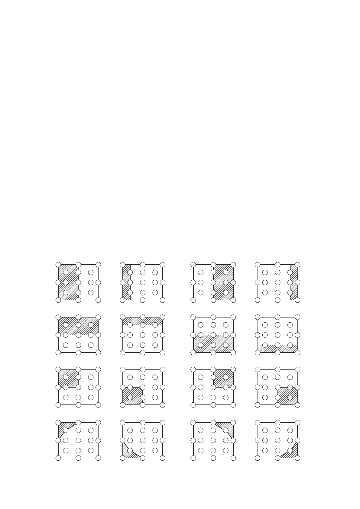
No. 2 deviation range No. 10 deviation range No. 3 deviation range No. 11 deviation range
14
10
15
12
6
4
2
1
5
7
13
16
8
3
11
9
17
14
10
15
12
4
6
2
1
5
7
13
16
8
3
11
9
17
14
10
15
12
6
4
2
1
5
7
13
16
8
3
11
9
17
14
10
15
12
4
6
2
1
5
7
13
16
8
3
11
9
17
No. 4 deviation range No. 12 deviation range No. 5 deviation range No. 13 deviation range
14
10
15
12
6
4
2
1
5
7
13
16
8
3
11
9
17
14
10
15
12
6
4
2
1
5
7
13
16
8
3
11
9
17
14
10
15
12
6
4
2
1
5
7
13
16
8
3
11
9
17
14
10
15
12
4
6
2
1
5
7
13
16
8
3
11
9
17
No. 6 deviation range No. 7 deviation range No. 8 deviation range No. 9 deviation range
14
10
15
12
6
4
2
1
5
7
13
16
8
3
11
9
17
14
10
15
12
6
4
1
2
5
7
13
16
8
3
11
9
17
14
10
15
12
6
4
2
1
5
7
13
16
8
3
11
9
17
14
10
15
12
4
6
2
1
5
5
7
13
16
8
3
11
9
17
No. 14 deviation range No. 15 deviation range No. 16 deviation range No. 17 deviation range
14
10
15
12
4
6
2
1
5
7
13
16
8
3
11
9
17
14
10
15
12
6
4
1
2
5
7
13
16
8
3
11
9
17
14
10
15
12
6
4
2
1
5
7
13
16
8
3
11
9
17
14
10
15
12
4
6
2
1
5
5
7
13
16
8
3
11
9
17
9
CP-S235 (C10SM2)
4-7 AIR-SENSOR adjustment
When the MAIN board or the SENSOR board is replaced, perform this adjustment after
completing reassembling the projector.
1. Open SERVICE MENU and choose AIR-SENSOR by using
Service menu comes up by following operation. Set the cursor on the OPTION menu and press the
MAGNIFY OFF button on the Remote controller. Next hold the MAGNIFY OFF button for 3 seconds or more.
2. Press the
automatically.
3. After the massage of "END" is displayed, check the Offset value displayed according to the following spec
Spec. : 150
4. If out of spec, confirm the below conditions Then retry the same adjustment.
(a) Installing the air filter correctly.
(b)
(c) Using the proper type of air filter.
(d) Installing the SENSOR board correctly.
(e) Connecting the proper wires to E7A1 and E981 firmly.
(f) The component I7A2 on the MAIN board stands vertically
(g) The component D981 on the SENSOR board stands vertically
button. Next press the [ ] button to select EXECUTE. The adjustment program runs
Offset: 227
Description
No obstruction and dust on air filter. (If not good condition, clean or replace
the air filter.)
button.
5. If the all conditions above is okay, replace the MAIN board.
10
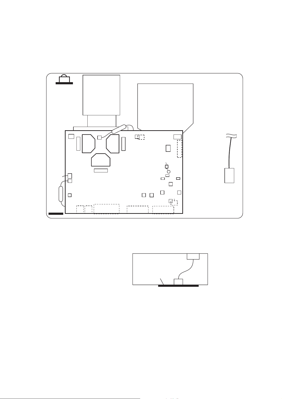
5. Troubleshooting
Check points
REMC
Board
CP-S235 (C10SM2)
E805
P701
E7A1
E301
ESPL
#6430
EA01
EV01
SENSOR Board
#6800
E302
P601
MAIN Board
E102
E802
P501
E803
(POWER)
S301
(P-ON)
E101
CONTROL
Board
E801
E804
D841
D302
(TEMP)
D301
S302
(INP)
E103
Rear view
E800
D303
C
(LAMP)
ET01
TSW
ET01
CNCT
11
EM01
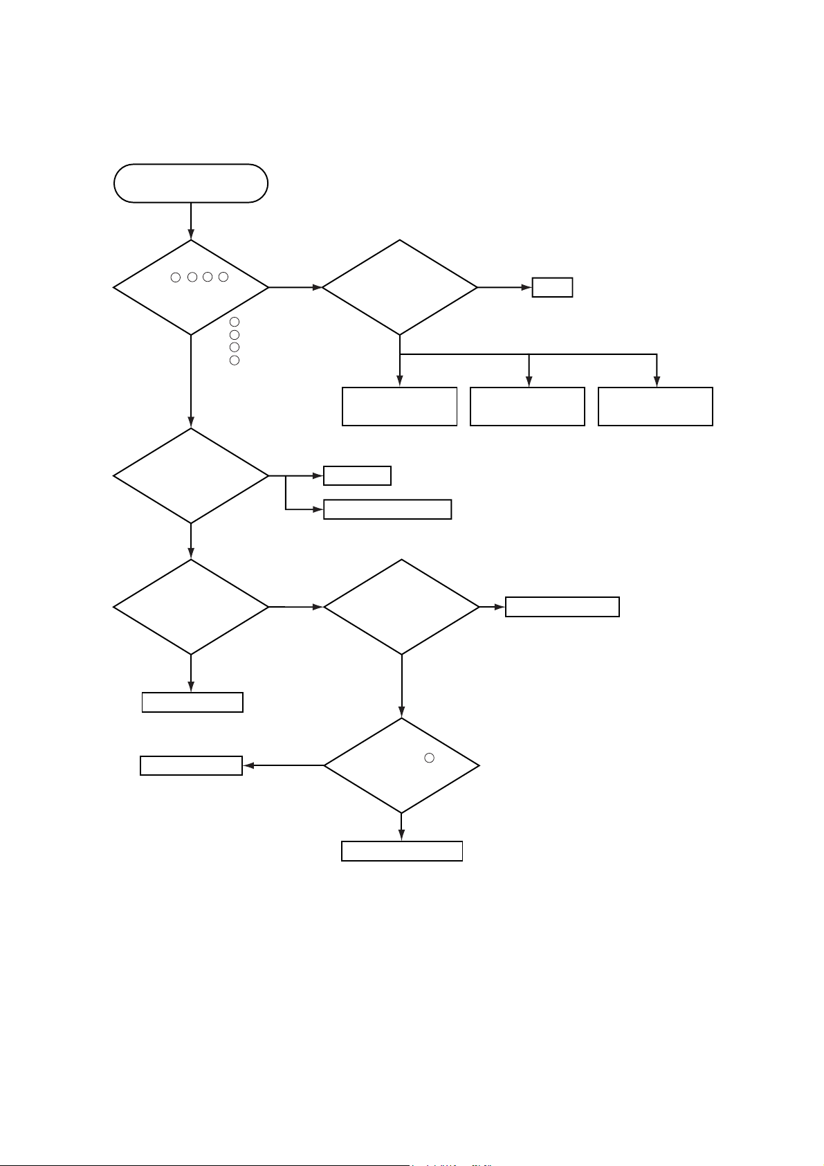
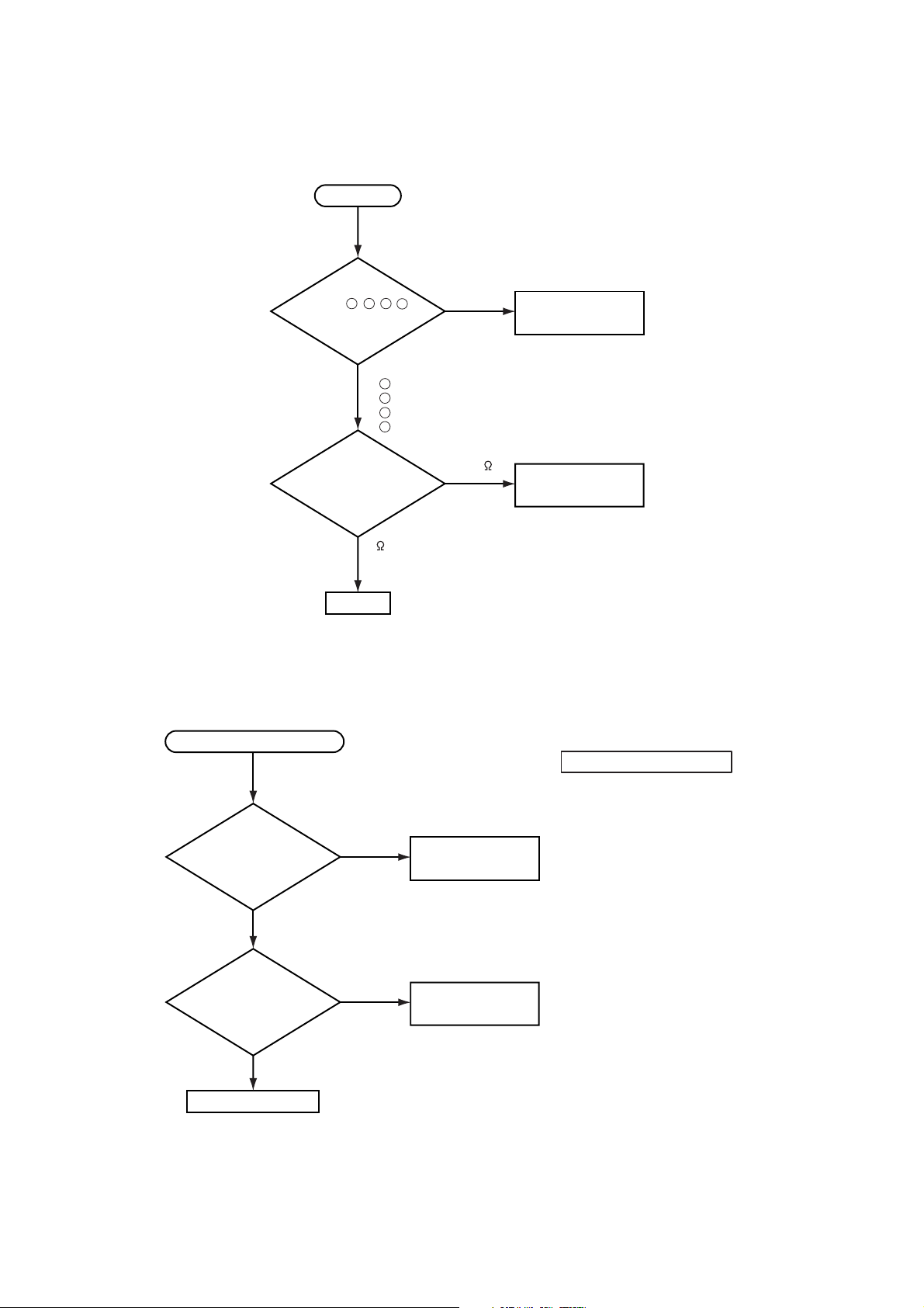
Power cannot be turned on
Are
voltage input
at pins , , , of
5 7
3
1
E800 on the MAIN
board at standby
mode?
YES
: +12V
1
: +17V
3
:+6.6V
5
:+4.1V
7
NO
CP-S235 (C10SM2)
Disconnect
TSW form Power unit
(circuit). And check
TSWshortor
open?
Short
Open
TSW
What is the state of
TEMP indicator D302?
No light
What is the state of
LAMP indicator D303?
No light
MAIN board
MAIN board
Blinks
Blinks
H (More than 12.6V)
Power unit (circuit)
DC FAN
Jump to * on the page 13
Is the LAMP DOOR
set?
OK
Measure
voltage at the of
2
E803 on the MAIN
board.
Fuse
on the Filter unit
NG
Set the LAMP DOOR
Filter unit
L(OV)
Limit SW board
12
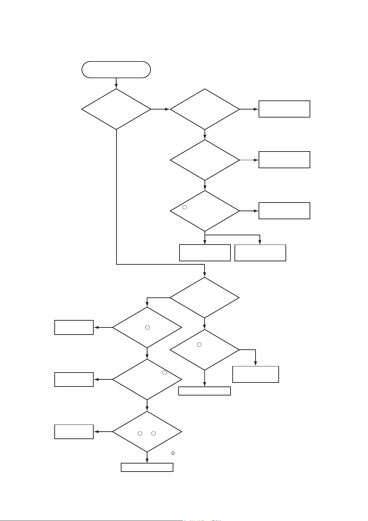
Lamp does not light
CP-S235 (C10SM2)
What is the
state of LAMP
indicator D303 during
operation?
No light
Light
Is the LAMP
installation correct?
YES
Change the lamp.
Does lamp light?
Not light
Is the
voltage at the
1
of E804 on the
MAIN board fixed to "L"
during warming-up?
"L"=0V
NO
Power unit (ballast)
NG
Light
YES
Power unit (circuit)
Install the Lamp
MAIN board
Lamp
DC FAN
(Lamp)
DC FAN
(Panel)
Thermistor A
(#6430)
H (3.3V)
NO
(Fan lock)
Infinity
Blinks
Measure
sure voltage at the
cathode pin of D841 on
of E801 have a amplitude
of 3.3V and a frequency
external air sensor
between and of #6430.
C
the MAIN board.
L(OV)
Does the
signal at the pin
of 40Hz or
more?
YES
(Normal)
Measure
the resistance of
1
(at disconnecting
2
from E302)
about 10k
1
*
What is the
state of TEMP indicator
D302?
No light
Is the voltage
3
at the of E804 on
the MAIN board
set to "L" during
warming-up?
YES
Power unit (ballast)
NO
"L" = 0V
MAIN board
MAIN board
13
CP-S235 (C10SM2)
Power unit (circuit)
NO
YES
Are
voltage input at
pins , , , of
E800 on the
MAIN board?
:+12V
:+17V
: +6.6V
: +4.1V
MAIN board
LCD module assembly
Check at operating mode
7
1
3
5
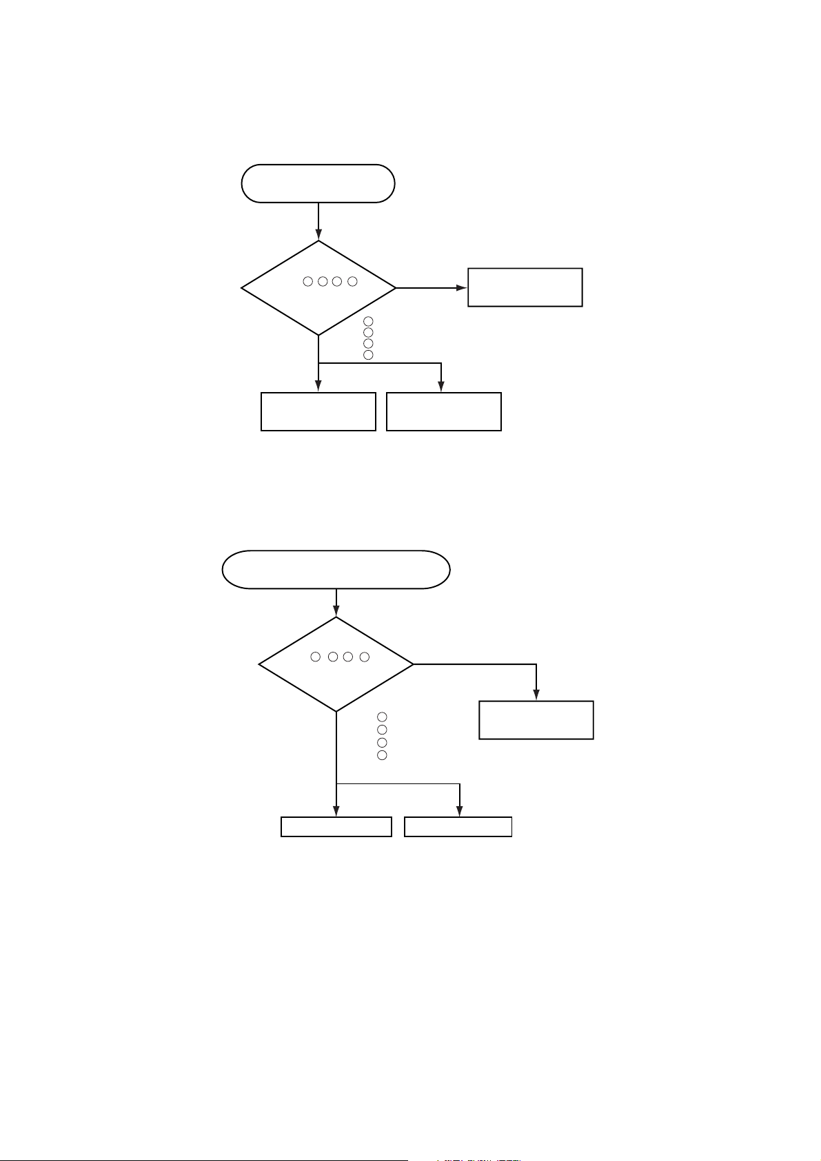
Picture is not displayed when the
VIDEO, S-VIDEO, Component Signal is input
7
1 3 5
Picture is not displayed
when the RGB signal is input
Check at operating mode
Are
voltage input
at pins , , , of
1 3 5 7
E800 on the
MAIN board?
1
YES
3
5
7
: +12V
: +17V
:+6.6V
:+4.1V
NO
Power unit
(circuit)
MAIN board
LCD panel
14
CP-S235 (C10SM2)
Speaker
Check at operating mode
No sound
NO
YES
Power unit (circuit)
Are
voltage input
at pin , , ,
of the E800 on the
MAIN board?
71 3 5
MAIN board
Turn off
the projector and
disconnect the Speaker
cable from ESPL.
Measure the resistance
of the Speaker.
: +12V
: +17V
: +6.6V
: +4.1V
7
1
3
5
about 8
0 or infinity
No control to RS-232C
Check the
RS-232C cable.
Are pin No. 2 and 3
crossed?
YES
Check the
power supply voltage
of E800 the voltage
correct?
YES
MAIN board
NO
NO
Use cross cable
Power unit (circuit)
15
The check after parts change
1. PC power supply OFF
2. Connection of cable
3. Projector starting
4. PC starting
*When not operating :
PC set up change of cable.
CP-S235 (C10SM2)
6. Service notes
6-1 Lead-free solder [CAUTION]
This product uses lead-free solder (unleaded) to help preserve the environment. Please read these instructions
before attempting any soldering work.
CAUTION
Always wear safety glasses to prevent fumes or molten solder from getting into the eyes. Lead-free solder can
splatter at high temperatures (600˚C).
Lead-free solder indicator
Printed circuit boards using lead-free solder are engraved with an "F."
Properties of lead-free solder
The melting point of lead-free solder is 40-50 ˚C higher than leaded solder.
Servicing solder
Solder with an alloy composition of Sn-3.0Ag-0.5Cu or Sn-0.7Cu is recommended.
Although servicing with leaded solder is possible, there are a few precautions that have to be taken. (Not taking
these precautions may cause the solder to not harden properly, and lead to consequent malfunctions.)
Precautions when using leaded solder
Remove all lead free solder from soldered joints when replacing components.
If leaded solder should be added to existing lead free joints, mix in the leaded solder thoroughly after the lead-
free solder has been completely melted (do not apply the soldering iron without solder).
Servicing soldering iron
A soldering iron with a temperature setting capability (temperature control function) is recommended.
The melting point of lead-free solder is higher than leaded solder. Use a soldering iron that maintains a high
stable temperature (large heat capacity), and that allows temperature adjustment according to the part being
serviced, to avoid poor servicing performance.
Recommended soldering iron:
Soldering iron with temperature control function (temperature range: 320-450˚C)
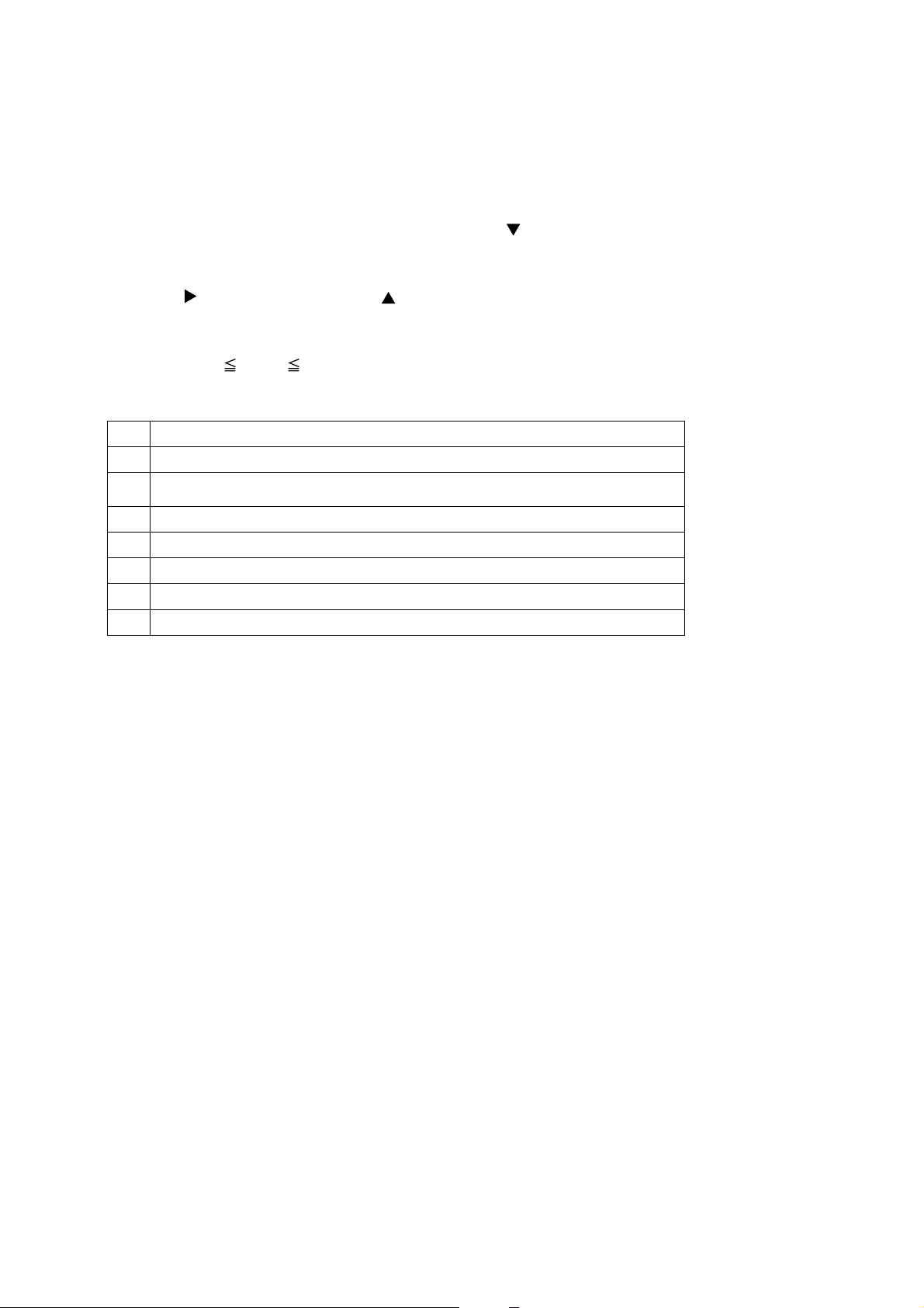
Recommended temperature range per part:
Part Soldering iron temperature
Mounting (chips) on mounted PCB 320 ±30˚C
Mounting (chips) on empty PCB 380 ±30˚C
Chassis, metallic shield, etc. 420 ±30˚C
MAIN board
SENSOR board
REMC board
COVER SW board
The boards using lead-free solder
POWER UNIT (BALLAST)
POWER UNIT (CIRCUIT)
FILTER UNIT
16
CP-S235 (C10SM2)
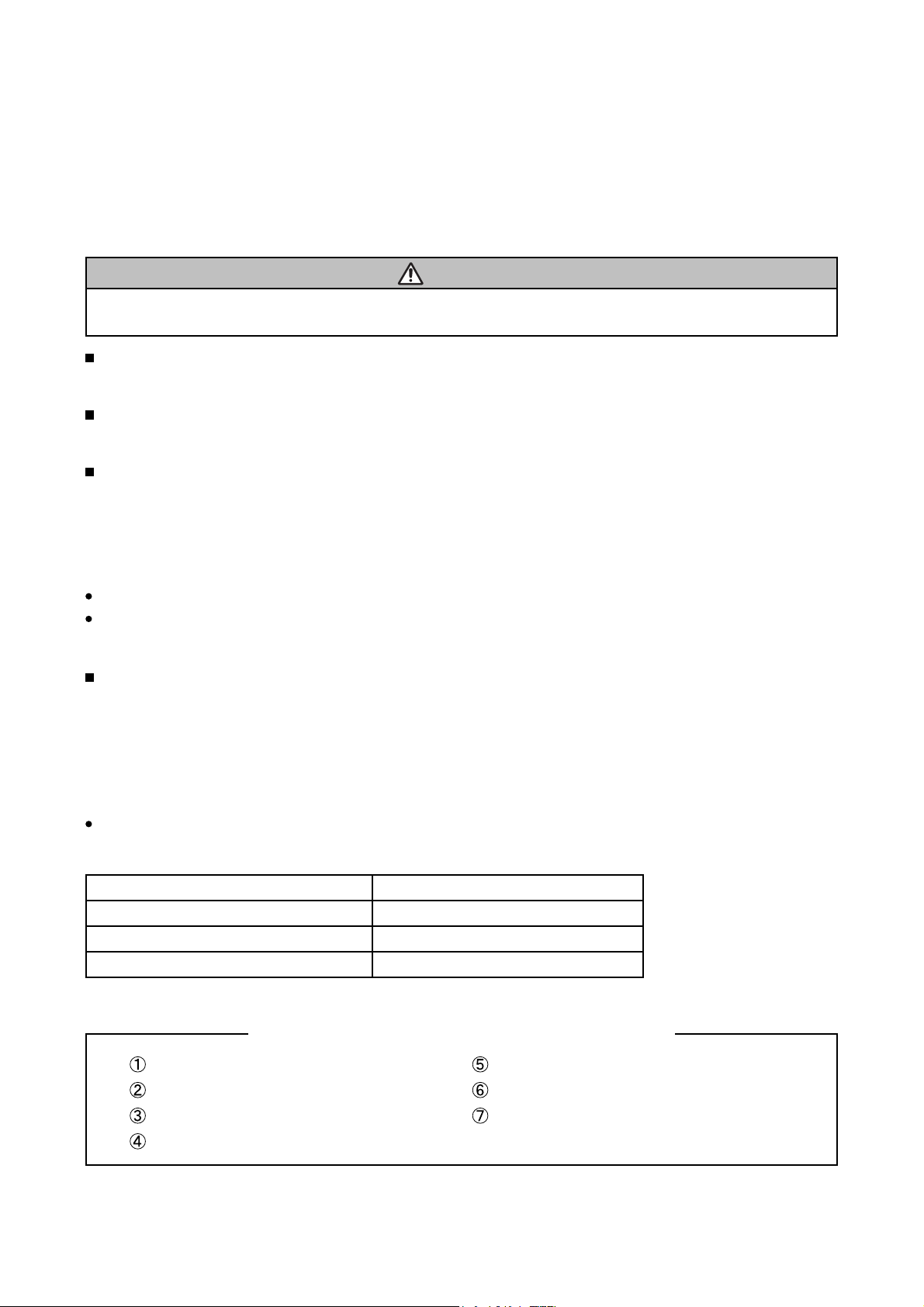
6-2 Cautions when removing the MAIN board
When removing the MAIN board, there is danger of damaging the connector connecting cables.
1) Disconnect 11 cables and remove 4 screws.
ATTENTION
Handling FPC cable
Be careful not to add strong load, such as pulling or twisting the FPC cable.
If load is added to FPC cable, convergence may shift.
In case FPC cable is being removing, or when attaching, or when opening a intake LID, or when closing,
please carry out carefully and slowly so that load is not added to FPC cable.
4 screws
MAIN Board
2) Remove 2 screw.
2 screw
AC IN
3) Lift the rear of the MAIN board to the front.
FRONT
MAIN Board
Lift
REAR
Disconnect the 2 cables.
6-3 Cautions when removing the power unit (BALLAST)
When removing the cable (CNBAR) connected to Power Unit (BALLAST), there is danger of damaging the small
PCB connecting cables.
Disconnect the CNBAR from connector CN200,
while pressing the sub-board
CNBAR
(to prevent the stress on the sub-board).
CN200
T102
CN100
Power Unit (BALLAST)
17
CP-S235 (C10SM2)
6-4 Before replacing the LCD/Lens prism
You should not separately replace the parts of the liquid crystal LCD/Lens prism because they only work properly
when used together. Therefore, you can either replace the LCD/Lens prism assembly or send the whole
LCD/Lens prism assembly unit back to HITACHI where we will replace the malfunctioning part,
recondition the device and send it back to you.
G Panel
DISTRIBUTOR HITACHI
Do not disassemble the unit
because replacement of separate
parts is not possible.
Replacement of G Panel Reconditioning
Return
6-5 Cleaning dust from panels and optical filters
1. Preparation
Prepare cleaning tools and materials as follows. Work in a relatively clean room so as to remove
additional dust while in removal operation.
(1) Swab for cleaning •••••• P#: NX08061, "Cotton stick L147"
(2) Air duster (Dust blower, spray can)
(3) Vacuum cleaner
2. Disassemble and open the maintenance hole.
(1) Turn off the projector, and unplug the power cord.
(2) Remove the top cover, according to the disassembling diagram of chapter 8.
(3) Remove the MAIN board, according to the Chapter 6-2.
(4) Remove the intake LID.
ATTENTION
Handling FPC cable
Be careful not to add strong load, such as pulling or twisting the FPC cable.
If load is added to FPC cable, Convergence may shift.
When the FPC cable is being removed, attached, when opening or closing a intake LID, perform the operation
carefully and slowly so that load is not added to FPC cable.
Release two latches
Intake LID
Lift
FPC cable
(5) Re-assemble the MAIN board and re-connect all the connectors.
18
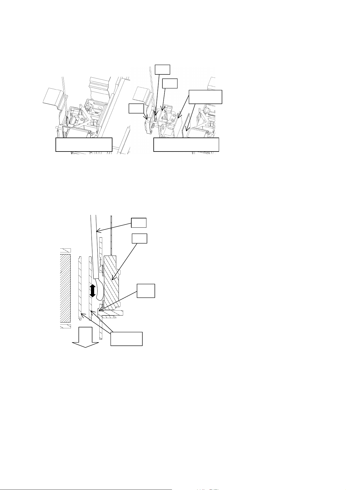
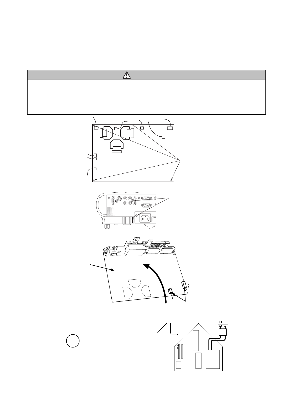
3. Maintenance point
CP-S235 (C10SM2)
Swab
Holder
Each colour part has same
construction.
Optical filters
Panel
By using swab and air duster,
you can easily remove dust from
panel and optical filters.
Separatied formationActua l formation
ᴾ
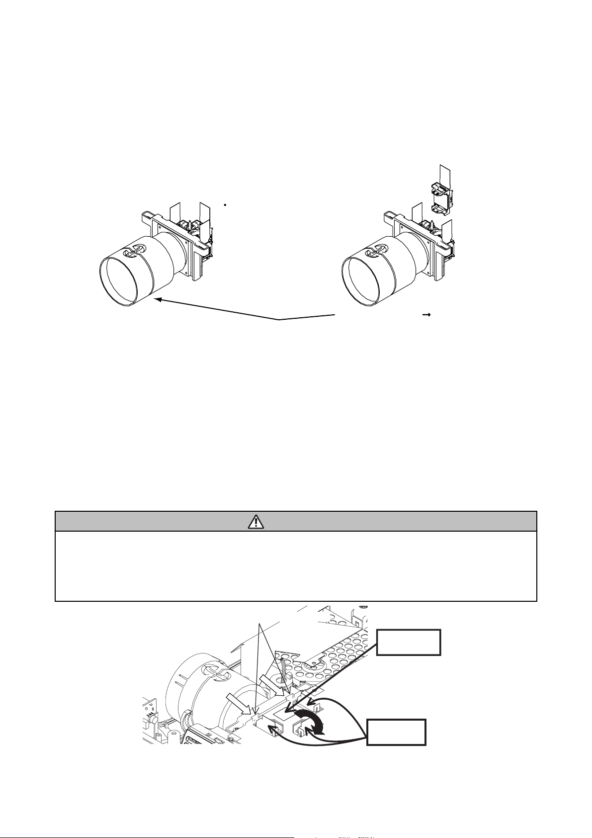
4. Cleaning the panels and optical filters
(1) Turn on the set and lit on the lamp.
(2) Set blank screen to black or white.
(3) By using swab and air duster, remove the dust. While cleaning you can check the dust on screen.
Swab
• While removing the dust, separated dust will be
blown off by air cooling system.
Panel
• Please pay attention not to damage panel and
filters.
Holder
Air
Optical filters
5. Re-assembly
(1) Turn off the set and remove the MAIN board.
(2) Set the intake LID.
(3) Re-assemble the MAIN board.
(4) Re-assemble the set.
(5) While re-assembling, clean the intake LID and intake filter and filter cover using a vacuum cleaner.
19
CP-S235 (C10SM2)
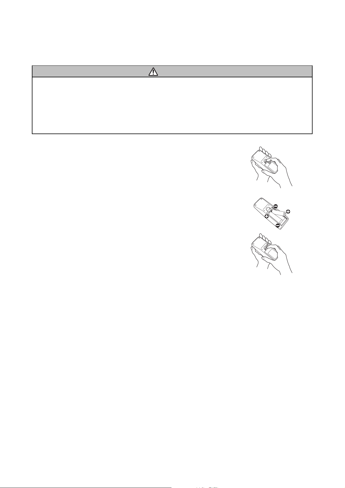
6-5 Putting batteries
CAUTION
Always handle the batteries with care and use them only as directed. Improper use may result in battery
cracking or leakage, which could result in fire, injury and/or pollution of the surrounding environment.
• Keep the battery away from children and pets.
•
Be sure to use only the batteries specifi ed for use with the remote control. Do not mix new batteries with used ones.
• When inserting batteries, verify that the plus and minus terminals are aligned correctly (as indicated in the
remote control).
• When you dispose the battery, you should obey the law in the relative area or country.
1. Remove the battery cover.
Slide back and remove the cover in the direction of the arrow.
2. Insert the batteries.
Align and insert the two AA batteries according to their plus and minus terminals.
(as indicated in the remote control.)
3. Close the battery cover.
Replace the cover in the direction of the arrow and snap it back into place.
20
 Loading...