

Page 1
TECHNICAL
9-1
TECHNICAL
Connection to the video signal terminals
Input signals
Signal input jacks
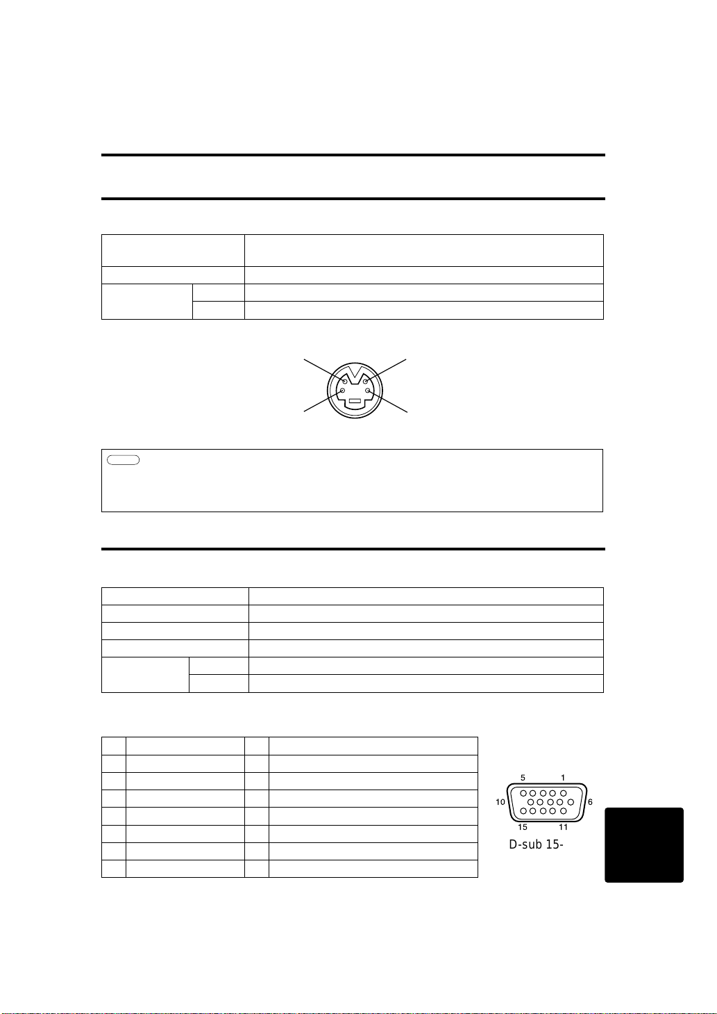
S-VIDEO input (mini DIN 4-pin)
Color signal
Ground
Ground
Brightness signal
S-VIDEO signal
Brightness signal 1.0Vp-p, 75Ω terminator
Color signal 0.286Vp-p (burst signal), 75Ω terminator
VIDEO signal 1.0Vp-p, 75Ω terminator
Audio signal
Input 200mV rms, 20kΩ or less (max. 3.0Vp-p)
Output 0~200mVrms,1kΩ
Caution
The priority sequence of the video input jacks is as follows.
(1) S-VIDEO input jack (2) RCA jack input jack
When video signals are being projected, the audio input by the video is output to the audio
output jack (RGB/VIDEO).
Input signals
Video signal Analog, 0.7Vp-p, 75Ω terminator (positive polarity)
Horizontal sync signal TTL level (positive/negative polarity)
Vertical sync signal TTL level (positive/negative polarity)
Compound sync signal TTL level
Audio signal
Input 200mVrms, 20kΩ or less (max. 3.0Vp-p)
Output 0~200mVrms,1kW
Signal input jacks
1 Video input (red) 9 N.C
2 Video input (green) 10 Ground
3 Video input (blue) 11 N.C
4 N.C 12 DDC jack (Display Data Channel)
5 N.C 13
Horizontal sync signal/compound sync signal
6 Ground (red) 14 Vertical sync signal
7 Ground (green) 15 DDC jack (Display Data Channel)
8 Ground (blue)
Connection to the RGB signal terminal
51
10
6
15
11
D-sub 15-pin
shrink jack
Page 2
9-2
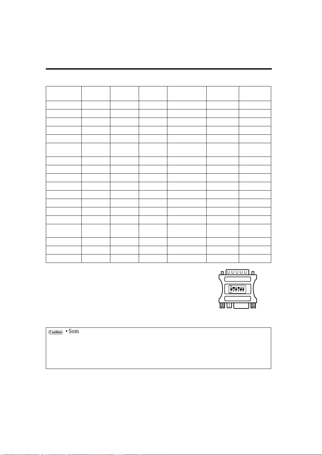
CCoonnnneeccttiioonn ttoo tthhee RRGGBB ssiiggnnaall tteerrmmiinnaall ((ccoonnttiinnuueedd))
Example of computer signal
Resolution H
× V
fH (kHz) fV (Hz) Rating Signal mode
Display
mode
Note 1
640 × 400
24.8 56.4 NEC PC9800 Zoom in
640 × 350
37.9 85.1 VESA VGA-1 Zoom in
640 × 400
37.9 85.1 VESA VGA-2 Zoom in
720 × 400
37.9 85.0 VESA TEXT Zoom in
640 × 480
31.5 59.9 VESA VGA-3 Zoom in
640 × 480
35.0 66.7 Mac13"mode Zoom in
SW 1 ON
SW 2 ON
640 × 480
37.9 72.8 VESA VGA-3(72Hz) Zoom in
640 × 480
37.5 75.0 VESA VGA-3(75Hz) Zoom in
640 × 480
43.3 85.0 VESA VGA-3(85Hz) Zoom in
800 × 600
35.2 56.3 VESA SVGA(56Hz)
800 × 600
37.9 60.3 VESA SVGA(60Hz)
800 × 600
48.1 72.2 VESA SVGA(72Hz)
800 × 600
46.9 75.0 VESA SVGA(75Hz)
800 × 600
53.7 85.1 VESA SVGA(85Hz)
832 × 624
49.7 74.5 Mac16"mode Zoom out
SW 2 ON
SW 4 ON
1024 × 768
48.4 60.0 VESA XGA(60Hz) Zoom out
1024 × 768
56.5 70.1 VESA XGA(70Hz) Zoom out
1024 × 768
60.0 75.0 VESA XGA(75Hz) Zoom out
Note 1: Mac adapter is necessary to the resolution mode.
Projector is compatible with 13 inch mode and 16 inch mode.
Mac 13" mode=switch 1 and switch 2 are ON.
Mac 16" mode=switch 2 and switch 4 are ON.
ON
OFF
123456
Caution
• Some computers may have multiple display screen modes. Use of some of these modes
will not be possible with this projector.
• Be sure to check jack type, signal level, timing and resolution before connecting this
projector to a computer.
• Depending on the input signal, full-size display may not be possible in some cases. Refer
to the number of display pixels above.
(Example 16 inch mode)
Page 3
9-3
CCoonnnneeccttiioonn ttoo tthhee RRGGBB ssiiggnnaall tteerrmmiinnaall ((ccoonnttiinnuueedd))
TECHNICAL
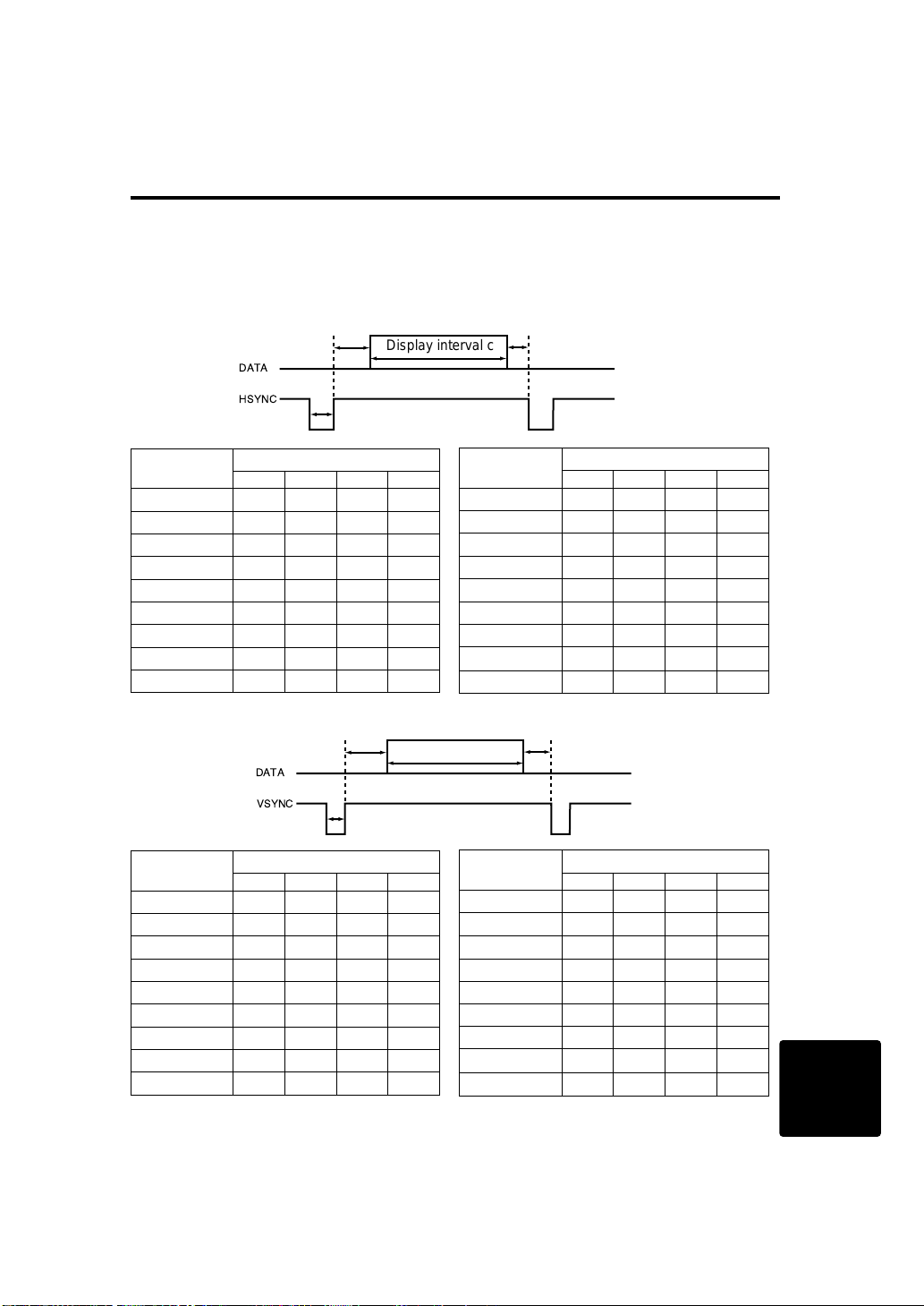
Initial set signals
The following signals are used for the initial settings.
The signal timing of some computer models may be different. In such case, refer to pages 17 and 18
and adjust the V.POSIT and H.POSIT of the menu.
DATA
HSYNC
DATA
VSYNC
Display interval c
Back porch b
Sync a
Front porch d
Display interval c
Back porch b
Sync a
Front porch d
Computer /
Signal
Horizontal signal timing (µs)
a b c d
VGA-1(85Hz) 2.0 3.0 20.3 1.0
VGA-2(85Hz) 2.0 3.0 20.3 1.0
PC-9800 3.0 3.8 30.4 3.0
TEXT 2.0 3.0 20.3 1.0
VGA-3 3.8 1.9 25.4 0.6
Mac 13"mode 2.1 3.2 21.2 2.1
VGA-3(72Hz) 1.3 3.8 20.3 1.0
VGA-3(75Hz) 2.0 3.8 20.3 0.5
VGA-3(85Hz) 1.6 2.2 17.8 1.6
Computer /
Signal
Horizontal signal timing (µs)
a b c d
SVGA(56Hz) 2.0 3.6 22.2 0.7
SVGA(60Hz) 3.2 2.2 20.0 1.0
SVGA (72Hz) 2.4 1.3 16.0 1.1
SVGA (75Hz) 1.6 3.2 16.2 0.3
SVGA (85Hz) 1.1 2.7 14.2 0.6
Mac 16"mode 1.1 3.9 14.5 0.6
XGA (60Hz) 2.1 2.5 15.8 0.4
XGA (70Hz) 1.8 1.9 13.7 0.3
XGA (75Hz) 1.2 2.2 13.0 0.2
Computer /
Signal
Vertical signal timimg (lines)
a b c d
VGA-1(85Hz) 3 60 350 32
VGA-2(85Hz) 3 41 400 1
PC-9800 8 25 400 7
TEXT 3 42 480 1
VGA-3 2 33 480 10
Mac 13"mode 3 39 480 3
VGA-3(72Hz) 3 28 480 9
VGA-3(75Hz) 3 16 480 1
VGA-3(85Hz) 3 25 480 1
Computer /
Signal
Vertical signal timimg (lines)
a b c d
SVGA(56Hz) 2 22 600 1
SVGA(60Hz) 4 23 600 1
SVGA (72Hz) 6 23 600 37
SVGA (75Hz) 3 21 600 1
SVGA (85Hz) 3 27 600 1
Mac 16"mode 3 39 624 1
XGA (60Hz) 6 29 768 3
XGA (70Hz) 6 29 768 3
XGA (75Hz) 3 28 768 1
Page 4
9-4
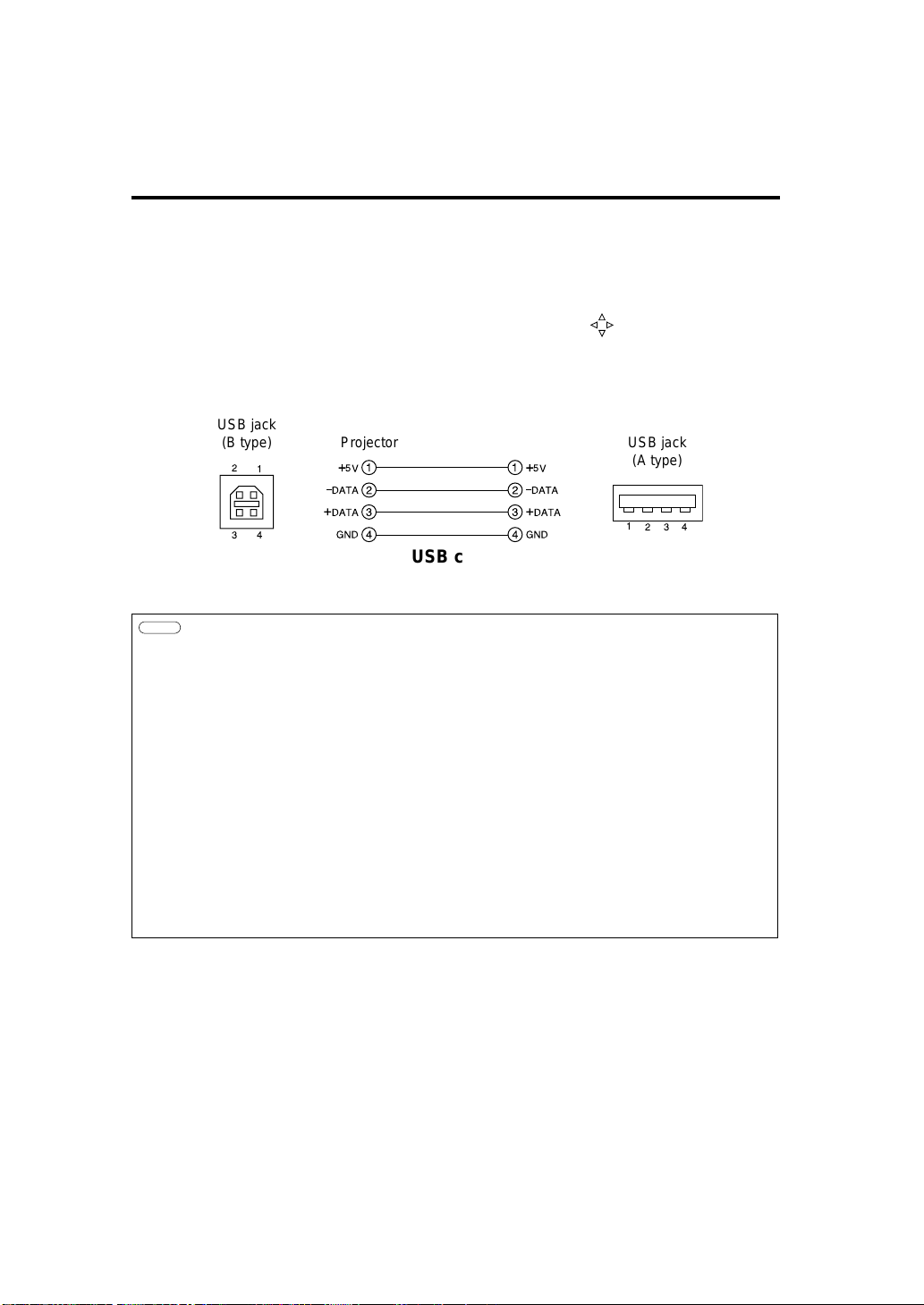
Connecting the USB
1. Connect the projector and computer with a suitable commercially available cable.
2. Press the INPUT button of the projector or the RGB 1/2 button of the remote control and select
the input where the computer is to be connected.
3. Start the mouse function.
4. Refer to page 10, 26 concerning the remote control of mouse operations.
5. The movement speed of the mouse varies according to time to push button.
6. The left click of the mouse can manipulate the right click of the MENUSELECT button, the
mouse with the RESET button.
1
2
3
4
1
2
3
4
+
5V
Ð
DATA
+
DATA
GND
+
5V
Ð
DATA
+
DATA
GND
1
234
2
1
3
4
USB jack
(B type)
USB jack
(A type)
Projector
USB cable
Computer
Caution
• Before making connections, read the instruction manual of the equipment to be
connected.
• Use the optional USB cable to connect.
• Effective with USB only when the mouse is used.
• Do not use with any device other than a personal computer.
• When using with Windows 95, it is necessary to set so that USB can be used with
version OSR 2.1 or higher. Depending on the kind or the virsion of the host controller,
operation may not be possible in some cases.
• In the case of notebook type computers with a built-in pointing device such as a track
ball, in some cases the built-in pointing device will have priority even if a mouse is
connected and the mouse may not be selected.
In such case, disable the built-in pointing device and change the BIOS setting (system
setup) so that an external mouse can be selected.
After changing the BIOS setting, perform the operations described in 1 - 3 above.
Refer to the computer hardware manual concerning the BIOS setting.
Also, some computers may not have a utility program to operate a mouse. Refer to the
computer hardware manual.
Page 5

9-5
Connection to the control signal terminal
TECHNICAL
Mouse functions
(1) Turn off the main power switches of the projector and computer and connect the two units with
the cable provided or an optional suitable commercially available cable. Disconnect the USB
cable from the projector.
(2) Turn on the main switch of the projector (the ON indicator lamp will light green).
(3) Press the INPUT button of the projector or the RGB button of the remote control and select the
input where the computer is to be connected.
(4) Turn on the computer power supply.
(5) Start the mouse function.
If the mouse has not been started, reboot the computer (soft reboot or reboot buttons).
(6) Refer to page 10 concerning remote control operation.
(7) The movement speed of the mouse varies according to time to push button.
(8) The left click of the mouse can manipulate the right click of the MENUSELECT button, the
mouse with the RESET button.
1
2
3
4
5
6
7
8
9
10
11
12
13
14
15
CLK
DATA
RTS
SEL0
GND
1
2
3
4
5
6
DATA
+5V
GND
CLK
6
3
4
2
1
+5V
5
15
6
10
11
15
control jack
D-sub 15-pin shrink jack
PS/2 Mouse
Projector Computer
Mouse jack Mini
DIN 6-pin
Mouse cable (PS/2)
Use the mouse cable provided or a PS/2 mouse cable (for IBM and compatibles).
Cables for ADB mouse (Apple), bus mouse (NEC) and serial mouse are available as options.
Mouse cable Product name Model
ADB mouse COE-MAC (ADB)-2 SC-MA201XC
Bus mouse COE-PC98 (BUS)-2 SC-MN201XC
Serial mouse COE-SERIAL-2 SC-MS201XC
Caution
•
Before making connections, read the instruction manual of the equipment to be connected.
• Turn off the projector and computer power supplies before connecting.
Connecting the mouse cable with the computer power on can result in a malfunction.
Use the mouse cable provided or an optional mouse cable to make the connection.
• In the case of notebook type computers with a built-in pointing device such as a track
ball, in some cases the built-in pointing device will have priority even if a mouse is
connected and the mouse may not be selected.
In such case, disable the built-in pointing device and change the BIOS setting (system
setup) so that an external mouse can be selected.
After changing the BIOS setting, perform the operations described in (1) - (3) above.
Refer to the computer hardware manual concerning the BIOS setting.
Also, some computers may not have a utility program to operate a mouse. Refer to the
computer hardware manual.
Page 6

9-6
Connection to the control signal terminal (continued)
CONTROL signal jack
Pin
no.
RS-
232C
Mouse
PS/2 ADB Serial BUS
1 YB
2 CLK
3 DATA DATA
4 XA
5 XB
6 SELO SELO SELO SELO
7 RTS RTS RTS RTS RTS
8 YA
9 +5V +5V +5V
10 GND GND GND GND GND
11 SW-L
12 SEL-1
13 RD
14 TD TD
15 SW-R
ADB (Mac) mouse
1
2
3
4
5
6
7
8
9
10
11
12
13
14
15
DATA
RTS
GND
1
2
3
4
ADB
+5V
GND
3
4
2
1
+5V
(POWER ON)
Mouse jack
Mini DIN 4-pin
Mouse cable (ADB) (option)
Projector Computer
Serial mouse
1
2
3
4
5
6
7
8
9
10
11
12
13
14
15
GND
TD
1
2
3
4
5
6
7
8
9
CD
RD
TD
DTR
GND
DSR
RTS
CTS
RI
1
2345
67
8
9
SELO
RTS
Mouse jack
D-sub 9-pin
Mouse cable (serial) (option)
Projector Computer
Page 7

9-7
CCoonnnneeccttiioonn ttoo tthhee ccoonnttrrooll ssiiggnnaall tteerrmmiinnaall ((ccoonnttiinnuueedd))
TECHNICAL
RS232C communication
(1) Turn off the projector and computer power supplies and connect with the RS232C cable.
(2) Turn on the computer power supply and, after the computer has started up, turn on the projector
power supply.
15
6
10
11
15
control jack
D-sub 15-pin shrink jack
1
2
3
4
5
6
7
8
9
10
11
12
13
14
15
RD
TD
GND
SELO
RTS
1
2
3
4
5
6
7
8
9
CD
RD
TD
DTR
GND
DSR
RTS
DTS
RI
1
2345
67
8
9
RS232C jack
D-sub 9-pin
RS232C cable
Projector Computer
2.1 Communications setting
19200bps , 8N1
2.2 Protocl
It is composed of the header (six bytes) + command data (six bytes).
2.2 Header
BE + EF + 03 + 06 + 00 + CRC_low + CRC_hige
CRC_low : CRC flag low-order one byte toward the command data six bytes
CRC_high : CRC flag high-order one byte toward the command data six bytes
2.3 Command data
byte_0 byte_1 byte_2 byte_3 byte_4 byte_5
Action Type Setting code
low high low high low high
Command data chart
Action (byte_0 - 1)
Action Classification Content
1 OPERATION_SET Change setting to the optional value.
2 OPERATION_GET Set value inside projector is read out.
3 OPERATION_INITIALIZE Return setting to the early value.
4 OPERATION_INCREMENT Increase one set value.
5 OPERATION_DECREMENT Decrease one set value.
6 OPERATION_EXECUTE A command is executed.
Page 8

9-8
CCoonnnneeccttiioonn ttoo tthhee ccoonnttrrooll ssiiggnnaall tteerrmmiinnaall ((ccoonnttiinnuueedd))
Requesting projector status
(1) Send the request code Header + Command data (‘02H’+‘00H’+‘xxH’+‘yyH’+‘00H’) from the
computer to the projector.
(2) The projector returns the response code ‘1DH’+ data to the computer.
Changing the projector settings
(1) Send the setting code Header + Command data (‘01H’+‘00H’+‘xxH’+‘yyH’+ data) from the
computer to the projector.
(2) The projector changes the setting based on the above setting code.
(3) The projector returns the response code ‘06H’ to the computer.
Using the projector default settings
(1) The computer sends the default setting code Header + Command data (‘06H’+‘00H’+‘xxH’+
‘yyH’+‘00H’) to the projector.
(2) The projector changes the specified setting to the default value.
(3) The projector returns the response code ‘06H’ to the computer.
When a command sent by the projector cannot be understood by the computer
(1) The computer sends the command code ‘01H’, ‘02xH’ or ‘06H’+‘00H’+‘xxH’+ ‘yyH’+‘00H’ to
the projector.
(2) When the command sent by the projector cannot be understood, the error command ‘15H’ is
returned by the computer.
When data sent by the projector cannot be practice
(1) The computer sends the command code ‘3xH’ , ‘4xH’ or ‘4xH’ + ‘yyH’ +data to the projector.
(2) When the command sent by the projector cannot be practice, the the error code ‘1cH’ +‘xxxxH’
is returned.
When the data length is greater than indicated by the data length code, the projector will ignore
the excess data code.
Conversely, when the data length is shorter than indicated by the data length code, an error code
will be returned to the projector.
Caution
• Operation cannot be guaranteed when the projector receives an undefined command or
data.
•
Provide an interval of at least 40ms between the response code and any other code.
Page 9

9-9
CCoonnnneeccttiioonn ttoo tthhee ccoonnttrrooll ssiiggnnaall tteerrmmiinnaall ((ccoonnttiinnuueedd))
TECHNICAL
Names Operation type
Header Command data
Magic
Number
Type Size CRC
Operati
on type
Oper-
ation
Setting code
Blank Color
Set
Red BE EF 03 06 00 3B D3 01 00 00 30 00 00
Orange BE EF 03 06 00 AD D2 01 00 00 30 01 00
Green BE EF 03 06 00 5B D2 01 00 00 30 02 00
Blue BE EF 03 06 00 CB D3 01 00 00 30 03 00
Purple BE EF 03 06 00 FB D1 01 00 00 30 04 00
Black BE EF 03 06 00 6B D0 01 00 00 30 05 00
White BE EF 03 06 00 9B D0 01 00 00 30 06 00
Get BE EF 03 06 00 08 D8 02 00 00 30 00 00
Mirror
Set
Normal BE EF 03 06 00 C7 D2 01 00 01 30 00 00
H Inverse BE EF 03 06 00 57 D3 01 00 01 30 01 00
V lnverse BE EF 03 06 00 A7 D3 01 00 01 30 02 00
H&V Inverse BE EF 03 06 00 37 D2 01 00 01 30 03 00
Get BE EF 03 06 00 F4 D2 02 00 01 30 00 00
Freeze
Set
Normal BE EF 03 06 00 83 D2 01 00 02 30 00 00
Freeze BE EF 03 06 00 13 D3 01 00 02 30 01 00
Get BE EF 03 06 00 B0 D2 02 00 02 30 00 00
Menu Color
Set
Red BE EF 03 06 00 7F D3 01 00 03 30 00 00
Orange BE EF 03 06 00 EF D2 01 00 03 30 01 00
Green BE EF 03 06 00 1F D2 01 00 03 30 02 00
BLUE BE EF 03 06 00 8F D3 01 00 03 30 03 00
Purple BE EF 03 06 00 BF D1 01 00 03 30 04 00
White BE EF 03 06 00 2F D0 01 00 03 30 05 00
Black BE EF 03 06 00 DF D0 01 00 03 30 06 00
Get BE EF 03 06 00 4C D3 02 00 03 30 00 00
Startup
Set
Turn ON BE EF 03 06 00 0B D2 01 00 04 30 00 00
Turn OFF BE EF 03 06 00 9B D3 01 00 04 30 01 00
Get BE EF 03 06 00 38 D2 02 00 04 30 02 00
Language
Set
English BE EF 03 06 00 F7 D3 01 00 05 30 00 00
Francais BE EF 03 06 00 67 D2 01 00 05 30 01 00
Deutsch BE EF 03 06 00 97 D2 01 00 05 30 02 00
Espanol BE EF 03 06 00 07 D3 01 00 05 30 03 00
Italiano BE EF 03 06 00 37 D1 01 00 05 30 04 00
Norsk BE EF 03 06 00 A7 D0 01 00 05 30 05 00
Nederlands BE EF 03 06 00 57 D0 01 00 05 30 06 00
Portuguese BE EF 03 06 00 C7 D1 01 00 05 30 07 00
Japanese BE EF 03 06 00 37 D4 01 00 05 30 08 00
Get BE EF 03 06 00 C4 D3 02 00 05 30 00 00
Command data chart
Page 10

9-10
Connection to the control signal terminal (continued)
Names Operation type
Header Command data
Magic
Number
Type Size CRC
Operation
type
Oper-
ation
Setting code
Magnify
Set BE EF 03 06 00 4F D2 01 00 07 30
00 00
(00 00 - 20 00)
Get BE EF 03 06 00 7C D2 02 00 07 30 00 00
Increment BE EF 03 06 00 1A D2 04 00 07 30 00 00
Decrement BE EF 03 06 00 CB D3 05 00 07 30 00 00
Timer
Set BE EF 03 06 00 0B 87 01 00 00 31
0R 00 (Default)
(00 00 - 63 00)
Get BE EF 03 06 00 C8 82 02 00 00 31 00 00
Increment BE EF 03 06 00 AE 82 04 00 00 31 00 00
Decrement BE EF 03 06 00 7F 83 05 00 00 31 00 00
OFF Timer
Set BE EF 03 06 00 TB 72 01 00 00 32
0R 00 (Default)
(00 00 - 63 00)
Get BE EF 03 06 00 C8 72 02 00 00 32 00 00
Increment BE EF 03 06 00 AE 72 04 00 00 32 00 00
Decrement BE EF 03 06 00 7F 73 05 00 00 32 00 00
Brightness Reset Execute BE EF 03 06 00 58 D3 06 00 00 07 00 00
Contrast Reset Execute BE EF 03 06 00 A4 D2 06 00 01 70 00 00
V.Position Reset Execute BE EF 03 06 00 E0 D2 06 00 02 70 00 00
H.Position Reset Execute BE EF 03 06 00 IC D3 06 00 03 70 00 00
H.Total Reset Execute BE EF 03 06 00 68 D2 06 00 04 70 00 00
Color Balance R Reset Execute BE EF 03 06 00 94 D3 06 00 05 70 00 00
Color Balance B Reset Execute BE EF 03 06 00 D0 D3 06 00 06 70 00 00
Aspect Reset Execute BE EF 03 06 00 2C D2 06 00 07 70 00 00
Video Format Reset Execute BE EF 03 06 00 38 D1 06 00 08 70 00 00
Sharpness Reset Execute BE EF 03 06 00 C4 D0 06 00 09 70 00 00
Color Reset Execute BE EF 03 06 00 80 D0 06 00 0A 70 00 00
TINT Reset Execute BE EF 03 06 00 7C D1 06 00 0B 70 00 00
Keystone Reset Execute BE EF 03 06 00 08 D0 06 00 0C 70 00 00
Mirror Reset Execute BE EF 03 06 00 F4 D1 06 00 0D 70 00 00
Blank Color Reset Execute BE EF 03 06 00 B0 D1 06 00 0E 70 00 00
Startup Reset Execute BE EF 03 06 00 4C D0 06 00 0F 70 00 00
Auto Execute BE EF 03 06 00 F3 93 06 00 07 14 00 00
Power On Execute BE EF 03 06 00 93 91 06 00 0F 14 00 00
Power Off Execute BE EF 03 06 00 47 96 06 00 10 14 00 00
Command data chart
Page 11

9-11
CCoonnnneeccttiioonn ttoo tthhee ccoonnttrrooll ssiiggnnaall tteerrmmiinnaall ((ccoonnttiinnuueedd))
TECHNICAL
Names Operation type
Header Command data
Magic
Number
Type Size CRC
Operation
type
Oper-
ation
Setting code
Input Source
Set
RGB BE EF 03 06 00 FE D2 01 00 00 20 00 00
Video BE EF 03 06 00 6E D3 01 00 00 20 01 00
SVideo BE EF 03 06 00 9E D3 01 00 00 20 02 00
Get BE EF 03 06 00 CD D2 02 00 00 20 00 00
Volume
Set BE EF 03 06 00 92 DD 01 00 01 02
15 00 (Default)
(00 00 - 2A 00)
Get BE EF 03 06 00 31 D3 02 00 01 02 00 00
Increment BE EF 03 06 00 57 D3 04 00 01 02 00 00
Decrement BE EF 03 06 00 86 D2 05 00 01 02 00 00
Mute
Set
Normal BE EF 03 06 00 46 D3 01 00 02 20 00 00
Mute BE EF 03 06 00 D6 D2 01 00 02 20 01 00
Get BE EF 03 06 00 75 D3 02 00 02 20 00 00
Brightness
Set BE EF 03 06 00 7A B3 01 00 03 20
80 00 (Default)
(00 00 - FF 00)
Get BE EF 03 06 00 89 D2 02 00 03 20 00 00
Increment BE EF 03 06 00 EF D2 04 00 03 20 00 00
Decrement BE EF 03 06 00 3E D3 05 00 03 20 00 00
Contrast
Set BE EF 03 06 00 0E B2 01 00 04 20
80 00 (Default)
(00 00 - FF 00)
Get BE EF 03 06 00 FD D3 02 00 04 20 00 00
Increment BE EF 03 06 00 9B D3 04 00 04 20 00 00
Decrement BE EF 03 06 00 4A D2 05 00 04 20 00 00
Color
Balance R
Set BE EF 03 06 00 F2 B3 01 00 05 20
80 00 (Default)
(00 00 - FF 00)
Get BE EF 03 06 00 01 D2 02 00 05 20 00 00
Increment BE EF 03 06 00 67 D2 04 00 05 20 00 00
Decrement BE EF 03 06 00 B6 D3 05 00 05 20 00 00
Color
Balance B
Set BE EF 03 06 00 B6 B3 01 00 06 20
80 00 (Default)
(00 00 - FF 00)
Get BE EF 03 06 00 45 D2 02 00 06 20 00 00
Increment BE EF 03 06 00 23 D2 04 00 06 20 00 00
Decrement BE EF 03 06 00 F2 D3 05 00 06 20 00 00
Keystone
Set BE EF 03 06 00 4A B2 01 00 07 20
80 00 (Default)
(00 00 - FF 00)
Get BE EF 03 06 00 B9 D3 02 00 07 20 00 00
Increment BE EF 03 06 00 DF D3 04 00 07 20 00 00
Decrement BE EF 03 06 00 0E D2 05 00 07 20 00 00
Aspect
Set
Normal BE EF 03 06 00 AE D7 01 00 08 20 0B 00
V compression BE EF 03 06 00 9E D5 01 00 08 20 0C 00
V/H compression
BE EF 03 06 00 0E D4 01 00 08 20 0D 00
V compression
H strech
BE EF 03 06 00 FE D4 01 00 08 20 0E 00
Get BE EF 03 06 00 AD D0 02 00 08 20 00 00
Command data chart
Page 12

9-12
Names Operation type
Header Command data
Magic
Number
Type Size CRC
Operation
type
Oper-
ation
Setting code
V.Position at
Stretch
Set
Default BE EF 03 06 00 62 D1 01 00 09 20 00 00
Bottom BE EF 03 06 00 F2 D0 01 00 09 20 01 00
Top BE EF 03 06 00 02 D0 01 00 09 20 02 00
Get BE EF 03 06 00 51 D1 02 00 09 20 00 00
V.Position
Get BE EF 03 06 00 0D 83 02 00 00 21 00 00
Increment BE EF 03 06 00 6B 83 04 00 00 21 00 00
Decrement BE EF 03 06 00 BA 82 05 00 00 21 00 00
H.Position
Get BE EF 03 06 00 F1 82 02 00 01 21 00 00
Increment BE EF 03 06 00 97 82 04 00 01 21 00 00
Decrement BE EF 03 06 00 46 83 05 00 01 21 00 00
H.Size
Get BE EF 03 06 00 B5 82 02 00 02 21 00 00
Increment BE EF 03 06 00 D3 82 04 00 02 21 00 00
Decrement BE EF 03 06 00 02 83 05 00 02 21 00 00
H.Phase
Get BE EF 03 06 00 49 83 02 00 03 21 00 00
Increment BE EF 03 06 00 2F 83 04 00 03 21 00 00
Decrement BE EF 03 06 00 FE 82 05 00 03 21 00 00
Video Format
Set
Auto BE EF 03 06 00 9E 75 01 00 00 22 0A 00
NTSC BE EF 03 06 00 FE 71 01 00 00 22 04 00
PAL50 BE EF 03 06 00 6E 70 01 00 00 22 05 00
SECAM BE EF 03 06 00 6E 75 01 00 00 22 09 00
NTSC 4.43 BE EF 03 06 00 5E 72 01 00 00 22 02 00
PAL M BE EF 03 06 00 FE 74 01 00 00 22 08 00
PAL N BE EF 03 06 00 0E 71 01 00 00 22 07 00
Gat BE EF 03 06 00 0D 73 02 00 00 22 00 00
Sharpness
Set BE EF 03 06 00 02 75 01 00 01 22
80 00 (Default)
(00 00 - FF 00)
Get BE EF 03 06 00 F1 72 02 00 01 22 00 00
Increment BE EF 03 06 00 97 72 04 00 01 22 00 00
Decrement BE EF 03 06 00 46 73 05 00 01 22 00 00
Color
Set BE EF 03 06 00 46 13 01 00 02 22
80 00 (Default)
(00 00 - FF 00)
Get BE EF 03 06 00 B5 72 02 00 02 22 00 00
Increment BE EF 03 06 00 D3 72 04 00 02 22 00 00
Decrement BE EF 03 06 00 02 73 05 00 02 22 00 00
Tint
Set BE EF 03 06 00 06 00 BA 12 01 00
80 00 (Default)
(00 00 - FF 00)
Get BE EF 03 06 00 49 73 02 00 03 22 00 00
Increment BE EF 03 06 00 2F 73 04 00 03 22 00 00
Decrement BE EF 03 06 00 FE 72 05 00 03 22 00 00
CCoonnnneeccttiioonn ttoo tthhee ccoonnttrrooll ssiiggnnaall tteerrmmiinnaall ((ccoonnttiinnuueedd))
Command data chart
Page 13

Hitachi America, Ltd.
Computor Division 2000 Sierra Point Parkway,
Brisbane, CA 94005-1835
Tel: +1-800-HITACHI Fax: +1-650-244-7776
Hitachi Sales Corp. of Canada
6740 Campobello Road, Mississauga, Ontario
L5N2L8, Canada
Tel: +1-905-821-4545 Fax: +1-905-821-1101
Hitachi Home Electronics (Europe), Ltd.
Dukes Meadow, Millboard Road, Bourne End ,
Buckinghamshire SL8 5XF UK
Tel: +44-162-864-3000 Fax: +44-162-864-3400
Hitachi Home Electronics Europe Ltd
426 Bergensesteenweg, 1500 Halle, Belgium
Tel: +32-2-363-9901 Fax: +34-2-363-9900
Hitachi Home Electronics Europe Ltd
Gewerbepark, Hintermattlistr, Postfach, 5506
Magenwil, Switzerland
Tel: +41-62-889-8011 Fax: +41-62-896-4771
Hitachi Europe GmbH
Business Systems Division
Via T. Gulli. 39, 20147 Milano, Italy
Tel: +39-2-487861 Fax: +39-2-48786322
Hitachi Sales Europe GmbH
Business Systems Division
Am Seestern 18, 40547 Dusseldorf, Germany
Tel: +49-211-529-1551 Fax: +49-211-529-1594
Hitachi Business Systems (Nordic)
Brugata 14, N-0184 Oslo, Norway
Tel: +47-2205-9060 Fax: +47-2205-9061
Hitachi Business Systems (Nordic)
Domnarvsgatan 29, Lunda, Box 62, S-163 91
Spanga, Sweden
Tel: +46-8-621-8260 Fax: +46-8-761-6250
Hitachi Business Systems (Nordic)
Kuldyssen 13, DK-2630 Tåstrup, Denmark
Tel: +45-43-99-9200 Fax: +45-43-99-9392
Hitachi Business Systems (Nordic)
Tapiolan Keskustorni 11 Krs. Fin-02100 Espoo,
Finland
Tel: +358-9-3487-1188 Fax: +358-9-455-2152
Hitachi France
Immeuble, 'Ariane', 18 Rue Grange Dame Rose,
B.P. 134, 78148 Velizy, Cedex, France
Tel: +33-1-34630542 Fax: +33-1-34650761
Hitachi Sales Iberica S A
Gran Via Carlos 111, 101, 1-1, 08028 Barcelona,
Spain
Tel: +34-3-330-8652 Fax: +34-3-339-7839
Hitachi Home Electronics Asia, (S) Pte Ltd.
16 Collyer Quay #20-00 Hitachi Tower Singapore
049318, Singapore
Tel: +65-536-2520 Fax: +65-536-2521
Hitachi Sales (Malaysia) Sdn. Bhd.
Wisma Hitachi, No.2, Lorong 13/6A, 46200
Petaling
Jaya, Selangor Darul Ehsan, Malaysia
Tel: +60-3-7573455 Fax: +60-3-7556090
Hitachi Sales (Thailand), Ltd.
994,996 Soi Thonglor, Sukhumvit 55 Road,
Klongton,
Klongtoey, Bangkok 10110, Thailand
Tel: +66-2-381-8381 Fax: +66-2-381-9520
Hitachi (Hong Kong), Ltd.
8th Floor Park-in Commercial Centre, No.56,
Dundas
Street, Kowloon Bay, Kowloon, Hong Kong
Tel: +852-2-7804351 Fax: +852-2-7804915
Hitachi Sales Corp. of Taiwan.
2nd Floor, No.65, Nanking East Road, Section 3,
Taipei, Taiwan
Tel: +886-2-516-0500 Fax: +886-2-516-1501
Hitachi Australia Ltd.
13-15 Lyonpark Road, North Ryde NSW 2113,
Australia
Tel: +61-2-9888-4100 Fax: +61-2-9888-4144
Hitachi, Ltd.
15-12, Nishi Simbashi 2-chome, Minato-ku, Tokyo,
105 Japan
Tel: +81-3-3502-2111 Fax: +81-3-3506-1440
QR000000
Printed in Japan
 Loading...