

Page 1
SERVICE MANUAL
MANUEL D'ENTRETIEN
WARTUNGSHANDBUCH
CAUTION:
Before servicing this chassis, it is important that the service technician read the “Safety
Precautions” and “Product Safety Notices” in this service manual.
No. 0414
CML171SXW
Data contained within this Service
manual is subject to alteration for
improvement.
ATTENTION:
Avant d’effectuer l’entretien du châassis, le technicien doit lire les «Précautions de sécurité»
et les «Notices de sécurité du produit» présentés dans le présent manuel.
VORSICHT:
Vor Öffnen des Gehäuses hat der Service-Ingenieur die „Sicherheitshinweise“ und „Hinweise
zur Produktsicherheit“ in diesem Wartungshandbuch zu lesen.
Les données fournies dans le présent
manuel d’entretien peuvent faire l’objet
de modifications en vue de perfectionner
le produit.
Die in diesem Wartungshandbuch
enthaltenen Spezifikationen können sich
zwecks Verbesserungen ändern.
Version Description Date
1.0 1. Original document 10.26.2001
1.1 2.Link file together 11.09.2001
SPECIFICATIONS AND PARTS ARE SUBJECT TO CHANGE FOR IMPROVEMENT
LCD Monitor
Oct 2001
Page 2

Hitachi CML171SXW LCD Monitor Service Manual (v1.1)
TABLE OF CONTENTS
1. Precaution and Notices … … … … . … … … … … … … … … … … … … … … 3
1.1 Safety Precaution … … … … . … … … … … … … … … … … … … … … . 3
1.2 Product Safety Notice … … … … … … … … … … … … … … … … … … 3
1.3 Service Notes … … … … … … … … … … … … … … … … … … … … … . 3
2. Specifications … … … … . … … … … … … … … … … … ... … … … … … … … 4
2.1 Monitor Specifications … … ..… … … … … … … … … … … … … … … . 4
2.2 Timing Supported – Analog Inputs .. … … … … … … … … … … … … . 5
3. Control Buttons and Functions … … … … … … … … … … … … … … … … . 6
4. Disassembly Instructions … … … … … … … … … … … … … … … … … … .. 6
5. General Connection and Applications … … … … … … … … … … … … … .. 9
5.1 Connecting the Monitor to the Computer … … … … … … … … … … .. 9
6. Electronic Circuit Description … … … … … … … … … … … … … … … … .. 10
7. Electronic Block Diagram … … … … … … … … … … … … … … … … … … 11
8. Troubleshooting Flow Chart … … … … … … … … … … … … … … … … … .. 12
Appendix A. PCB Circuit
Appendix B. PCB Layout
Appendix C. PCB and Accessory Part List
Appendix D. Mechanical Part List
Appendix E. Pack and Other Part List
Appendix F. Service Parts List
Appendix G. Mechanical Disassembly
2
Page 3

Hitachi CML171SXW LCD Monitor Service Manual (v1.1)
1. Precautions and Notices
1.1 Safety Precautions
Although LCD monitors are displays without high voltage as that in the CRTs, the
following precautions still should be take care of.
1) Observe all cautions and safety related notes located inside the display cabinet and on
the display chassis.
2) Operation of these displays outside the cabinet or with the cover removed involves a
shock hazard from the display backlight’s inverter. Work on the display should not be
attempted by anyone who is not thoroughly familiar with precautions necessary when
working on high voltage equipment.
3) Before returning a serviced display to the customer, a thorough safety test must be
performed to verify that the display is safe to operate without danger or shock.
1.2 Product Safety Notice
1) Many electrical and mechanical parts in this chassis provide special visual safety
protection. The protection afforded by them cannot necessarily be obtained by using
replacement components rated for higher voltage, wattage, etc.
2) Before replacing any of these components, read the parts list manual carefully. The use
of substitute replacement parts, which do not have the same safety characteristics, as
specified in the parts list may create shock, fire or other hazards.
1.3 Service Notes
1) When replacing parts or circuit boards, wrap the wires around terminals before
soldering.
2) Keep wires away from high temperature components.
3) Keep cable and their shielding in their original position so as to reduce interference.
3
Page 4

Hitachi CML171SXW LCD Monitor Service Manual (v1.1)
2. Specifications
2.1 Monitor Specification
LCD Module 17-in, active matrix TFT, anti-glare coating, 0.264 mm pixel pitch
Display Size 337.9 mm x 270.3 mm
Viewing Angle
Left/Right
Up/Down
60° / 60°(Typical)
40° /60°(Typical)
Luminance
Contrast Ratio
Display Colors 16.7 million
Power Input 100 ~ 240 VAC Full Range, 50/60 Hz (External AC adapter)
Maximum power
consumption
Signal Input
Video Signal
Sync signals
Line (horizontal)
frequency
Raster (vertical)
frequency
Pixel dot clock 135 MHz (maximum)
Recommended mode 1280 x 1024 @ 60 Hz
Pedestal tilt
230 cd/m2 (Typical)
300 : 1 (Typical)
< 45W
RGB positive 0.7VPP, 75ohm
Separate & Composite, TTL Level
31.5 kHz ~ 80 kHz
56 Hz ~ 75 Hz
20° forward, -5°backward
Dimensions
(W x H x D)
Weight 7.0 kg
Operating Conditions
Temperature
Humidity
Altitude
Storage Conditions
Temperature
Humidity
Altitude
424 x 438 x 86 mm (without base)
5° ~ 40°C at altitude 0 ~ 2000m
5° ~ 30°C at altitude 2000 ~ 3000m
20% ~ 85% RH, non-condensing
3000m Max.
-20° ~ 60°C
5% ~ 95% RH
10000m Max.
4
Page 5
Hitachi CML171SXW LCD Monitor Service Manual (v1.1)
2.2 – Analog Inputs
Mode
No.
1 VGA 60HZ
2 VGA 72HZ
3 VGA 75HZ
4 SVGA 56HZ
5 SVGA 60HZ
6 SVGA 72HZ
7 SVGA 75HZ
8 XGA 60HZ
9 XGA 70HZ
10 XGA 75HZ
11 SXGA 60HZ
12 SXGA 75HZ
13 MAC SVGA
14 MAC SVGA
15 US TEXT
16 VGA 70HZ
Mode Name
Resolution
640*480
640*480
640*480
800*600
800*600
800*600
800*600
1024*768
1024*768
1024*768
1280*1024
1280*1024
640*480
832*624
720*400
640*350
H.Freq.(KHZ)
V.Freq.(HZ)
31.469
59.941
37.804
72.81
37.5
75.0
35.156
56.25
37.879
60.317
48.077
72.188
46.875
75.0
48.363
60.004
56.476
70.069
60.023
75.029
63.981
60.020
79.976
75.025
35.0
66.667
49.725
74.550
31.469
70.087
31.469
70.087
H. Polarity
V. Polarity
-
-
-
-
-
-
+
+
+
+
+
+
+
+
-
-
-
-
+
+
+
+
+
+
-
-
-
-
-
+
+
-
Pixel CLK
(MHZ)
25.175
31.5
31.5
36.0
40.0
50.0
49.5
65.0
75.0
78.75
108
135
30.24
57.283
28.322
25.175
Note: The display is capable of going beyond these recommended modes.
5
Page 6

Hitachi CML171SXW LCD Monitor Service Manual (v1.1)
3. Control Buttons and Functions
There are four control buttons located at the lower part of the front panel of your display:
ð POWER: Push to turn on or turn off the display. The power indicator (Green) will light
while the display is on.
ð Select: Display the On-Screen Display (OSD) “Main Menu” , selects items for user
adjustment, and execute the function selected.
Note: Hold down this key for 2 seconds will clear OSD menu.
ð Up(△): Move upward through the choice in the OSD submenu. If an adjustment bar is
displayed, this button increases the setting value.
Note: This key is also used as ‘direct key’ to bring-up OSD “Audio Menu”.
ð Down(▽): Move downward through the choice in the OSD submenu. If an adjustment bar
is displayed, this button decreases the setting value.
Note: This key is also used as ‘direct key’. When the OSD “Main Menu” is inactive, press
this key will execute ‘Auto Setup’ function.
For detailed control functions, please refer to the User’s Manual
4. Disassembly Instructions
To disassembly the monitor, follow the steps as below:
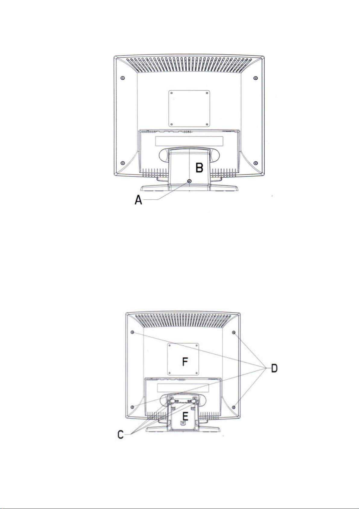
1) Face Down the Monitor.
Note: Face down the monitor on a smooth plane with a soft material on that plane to
protect the panel faceplate.
2) Hinge Cover Removal
As below, remove the screw indicated by “A” from the hinge cover, and then remove the
hinge cover (indicated by “B”) for the base.
6
Page 7
Hitachi CML171SXW LCD Monitor Service Manual (v1.1)
3) Base and Back Cover Removal:
As below, after removing the hinge cover, there will be 4 screws (indicated by “C”), and
remove them. Then you can remove the whole base of the monitor.
Remove 4 screws indicated as “D” of the back cover. Then remove the back cover with
care .
7
Page 8
Hitachi CML171SXW LCD Monitor Service Manual (v1.1)
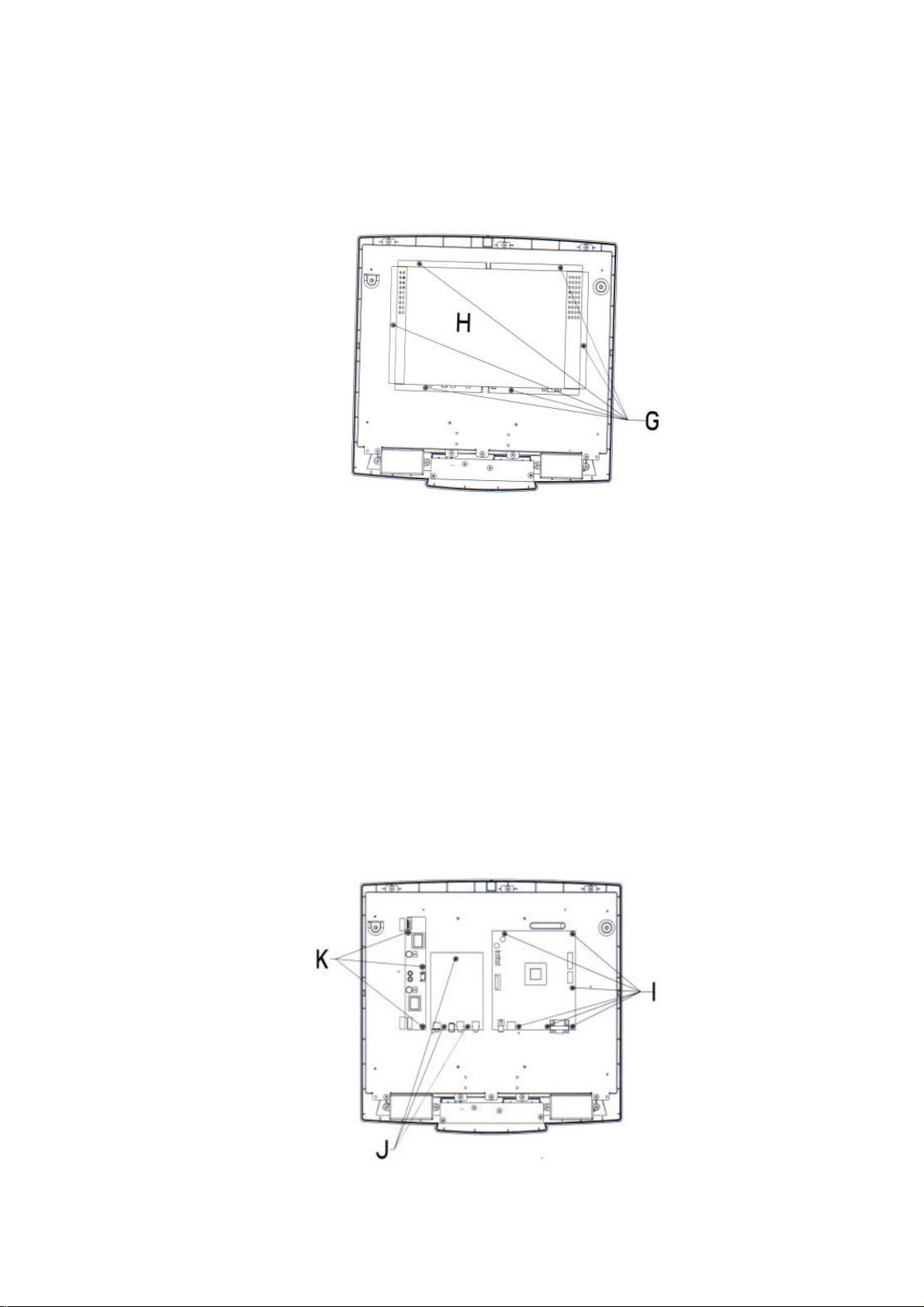
4) Metallic Cover Removal:
Remove 6 screws indicated as “G” from the back metallic cover. Then remove the back
metallic cover.
5) PCB Assembly Removal:
Caution: When serving or replacing the panel, disconnect the DC power jack completely.
(a) Unplug all connected wires from the PCB.
(b) Remove 3 screws indicated as “K” from the inverter board, and then remove the board
carefully.
(c) Remove 2 screws indicated as “J” from the audio board, and then remove the board
carefully.
(d) Remove 7 screws indicated as “I” from the main board connected with front cover.
8
Page 9
Hitachi CML171SXW LCD Monitor Service Manual (v1.1)
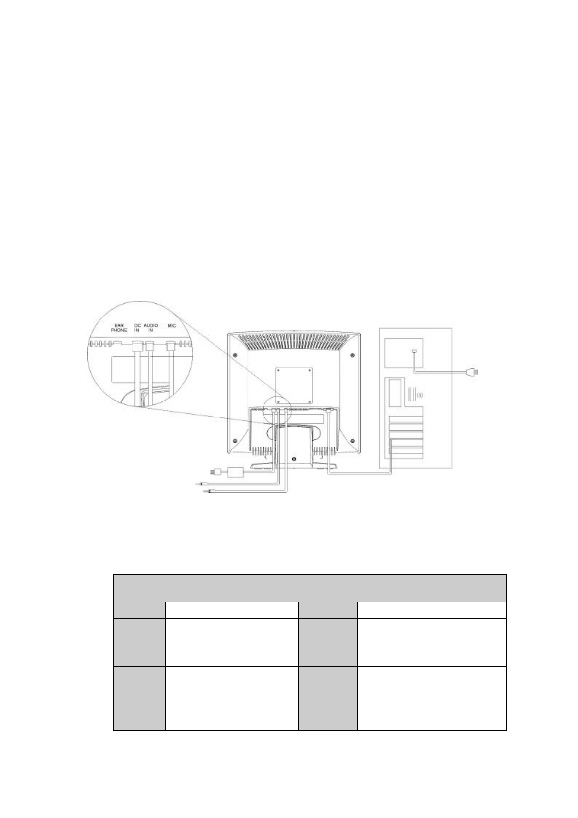
5. General Connection and Applications
Procedures for installing and using this CML171SX LCD monitor are described as
below.
5.1 Connecting the monitor to the computer
1) Place the display on a flat, sturdy surface. Choose an area free from excessive heat,
moisture, and sunlight. Avoid possible sources of electromagnetic interference, such as
transformers, motors, and fluorescent lighting.
2) Locate the AC power adapter with attached power cable and then connect the power cable
to the power jack on the back of the display. Plug the three-prong power cord into a power
outlet, and plug the other end into the AC power adapter. The three-prong power cord is a
shielded type and is provided as a safety precautions to ensure proper electrical grounding.
Plug the D-SUB 15-pin analog signal cable into the Analog Input port on the back of the
display. Connect the other end of the signal cable into your computer’s VGA output port. The
assignment of the pins of the connector is as follows:
Pin Assignment of 15-pin D-SUB connector
1
2
3
4
5
6
7
8
Red Video
Green Video
Blue Video
Monitor Ground
DDC-Return
Red Ground
Green Ground
Blue Ground
9
10
11
12
13
14
15
9
+5V for DDC circuit
Logic Ground
Monitor Ground
DDC-Serial Data
H-Sync.
V-Sync.
DDC-Serial Clock
Page 10

Hitachi CML171SXW LCD Monitor Service Manual (v1.1)
10
3) First turn the PC power switch ON. Then apply power to the display by pressing the power
button to turn the monitor on. The power indicator LED will then illuminate.
Note: Do not force the cable into the connector; line it up carefully so that you don’t
bend the pins.
6. Electronic Circuit Description
6.1 PCB Board Circuit
The circuit diagrams of main board (PWB-0393) audio board (PWB-0396)
Inverter (PWB-0351) key board (PWB-0392) are shown in is shown in
Appendix A
6.2 PCB Layout
The PCB Layout of main board (PWB-0393) audio board (PWB-0396)
Inverter (PWB-0351) key board (PWB-0392) are shown in is shown in
Appendix B
Page 11

7. Electronic Block Diagram
ANALOG R.G.B INPUT
LVDS
Gm5020
RED
GREEN
BLUE
H_SYNC
V_SYNC
SCL
SDA
12V
Switching
/Regulator
Audio in
24WC02
(DDC2B)
3.3V
5V
PLL
ADC
OSD
SCALER
292 pin PBGA Package
MICROCONTROLLER
Audio Ampilier
TFT
LCD
LVDS
PANEL
INVERTER
Speaker/Earphone
Page 12

8. Troubleshooting Flow Chart
12
Page 13

Hitachi CML171SXW LCD Monitor Service Manual (v1.0)
APPENDIX A
Schematic Diagrams
Frame Store Circuit
Host Circuit
Input Connector (L7CHT) Circuit
Output Interface Circuit
Power Circuit
Video Decoder
Audio Circuit
Inverter Circuit
Keyboard Circuit
Page 14

Page 15

Page 16

Page 17

Page 18

Page 19

Page 20

Audio Circuit
Model Number: PWB-0396
No:
Update:
Filename: PWB-0396-1 sch Sheet 1 of 1
Drawn by:
Rev 01
Page 21

Inverter Circuit
Model No: PWB-0351 TIV-11
No. Drawn by:
Update
Filename: PWB-0351 sch
Sheet 1 of 1
Rev. C
Page 22

Keyboard Circuit
Update:
Filename:
Model No. Keyboard
Rev. 01
Drawn by:
Sheet 1 of 1
Page 23

Hitachi CML171SXW LCD Monitor Service Manual (v1.0)
APPENDIX B
PCB Boards
The layout diagrams of Mainboard (PWB0393), Audio Board (PWB0396),
Inverter (PWB0351) & Key Board (PWB0392) are shown in the next pages.
Page 24

Mainboard PWB-0393
Page 25

Audio Board PWB-0396
Page 26

Inverter Board PWB-0351
Page 27

Key Board PWB-0392
Page 28

THE UPDATED PARTS LIST
FOR THIS MODEL IS
AVAILABLE ON ESTA
Page 29

Appendix G
Page 30

Hitachi, Ltd. Tokyo, Japan
International Sales Division
THE HITACHI ATAGO BUILDING,
No. 15 –12 Nishi Shinbashi, 2 – Chome,
Minato – Ku, Tokyo 105-8430, Japan.
Tel: 03 35022111
HITACHI EUROPE LTD,
Whitebrook Park
Lower Cookham Road
Maidenhead
Berkshire
SL6 8YA
UNITED KINGDOM
Tel: 01628 643000
Fax: 01628 643400
Email: consumer-service@hitachi-eu.com
HITACHI EUROPE GmbH
Munich Office
Dornacher Strasse 3
D-85622 Feldkirchen bei München
GERMANY
Tel: +49-89-991 80-0
Fax: +49-89-991 80-224
Hotline: +49-180-551 25 51 (12ct/min)
Email: HSE- DUS.service@hitachi-eu.com
HITACHI EUROPE srl
Via Tommaso Gulli N.39, 20147
Milano, Italia
ITALY
Tel: +39 02 487861
Tel: +39 02 38073415 Servizio Clienti
Fax: +39 02 48786381/2
Email: customerservice.italy@hitachi-eu.com
HITACHI EUROPE S.A.S
Lyon Office
B.P. 45, 69671 BRON CEDEX
FRANCE
Tel: 04 72 14 29 70
Fax: 04 72 14 29 99
Email: france.consommateur@hitachi-eu.com
HITACH EUROPE AB
Egebækgård
Egebækvej 98
DK-2850 Nærum
DENMARK
Tel: +45 43 43 6050
Fax: +45 43 60 51
Email: csgnor@hitachi-eu.com
Hitachi Europe Ltd
Bergensesteenweg 421
1600 Sint- Pieters-Leeuw
BELGIUM
Tel: +32 2 363 99 01
Fax: +32 2 363 99 00
Email: sofie.van.bom@hitachi-eu.com
www.hitachidigitalmedia.com
HITACHI EUROPE S.A.
364 Kifissias Ave. & 1, Delfon Str.
152 33 Chalandri
Athens
GREECE
Tel: 1-6837200
Fax: 1-6835964
Email: service.hellas@hitachi-eu.com
HITACHI EUROPE S.A.
Gran Via Carlos III, 101- 1
08028 Barcelona
SPAIN
Tel: 93 409 2550
Fax: 93 491 3513
Email: atencion.cliente@hitachi-eu.com
HITACHI Europe AB
Box 77 S-164 94 Kista
SWEDEN
Tel: +46 (0) 8 562 711 00
Fax: +46 (0) 8 562 711 13
Email: csgswe@hitachi-eu.com
HITACHI EUROPE LTD (Norway) AB
STRANDVEIEN 18
1366 Lysaker
NORWAY
Tel: 67 5190 30
Fax: 67 5190 32
Email: csgnor@hitachi-eu.com
HITACHI EUROPE AB
Neopoli / Niemenkatu 73
FIN-15140 Lahti
FINLAND
Tel : +358 3 8858 271
Fax: +358 3 8858 272
Email: csgnor@hitachi-eu.com
HITACHI EUROPE LTD
Na Sychrove 975/8
101 27 Praha 10 – Bohdalec
CZECH REPUBLIC
Tel: +420 267 212 383
Fax: +420 267 212 385
Email: csgnor@hitachi-eu.com
 Loading...