

Page 1
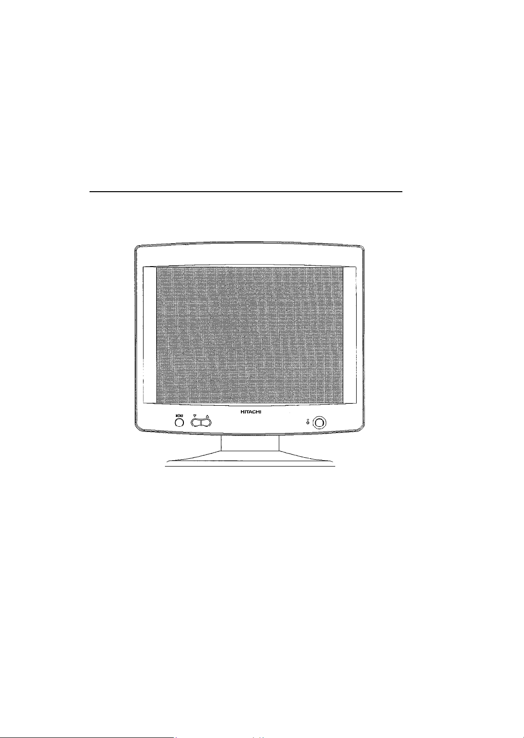
HITACHI
Color LCD Monitor
CML151XW
User’s
Manual
Thank you for purchasing Hitachi’s Liquid Color Display.
Please read the User’s Manual carefully and store
guarantee.
l
Please read and make sure you fully understand the safety precautions
before use.
Please keep this User’s Manual
.
in a
handy location for easy reference.
in a
safe place along with the
Page 2

Page 3

W
Important Notice
. No portion of this manual in part
or
whole may be reproduced without permission.
. The contents of this manual may be changed without prior notice.
. If any discrepancies or errors should be found in this manual, please notify the
dealer where this product was purchased.
. Please note that Hitachi assumes no responsibility for any damages
or
loss
incurred during the use of this product.
l About ENERGYSTAR@
As participant in the International
determined that this product meets the International
ENERGYSTAR
program, HITACHI has
ENERGYSTAR
program
standards.
“The International
ENERGYSTAR
Program
is an
international program that
promotes energy saving during use of computers and other office equipment. This
program supports the development and distribution of products with functions that
effectively reduce energy consumption. It
proprietors can participate voluntarily.
equipment such
as
computers, displays, printers, facsimiles, and copiers.
is an
open system in which business
Applicable products include office
Standards and logos are uniform throughout participating nations.”
l
FCC (Federal Communications Commission) STATEMENT WARNING
WARNING :
B
digital device, pursuant to Part 15 of
reasonable protection against harmful interference in a residential installation.
equipment generates, uses, and can radiate radio frequency energy and, if
This equipment has been tested and found to comply with the limits for a Class
the
FCC Rules. These limits
are
designed to provide
This
not
installed and
used in accordance with the instructions, may cause harmful interference to radio
communications. However, there is no guarantee that interference will not occur in
particular installation. If this equipment does cause harmful interference to radio
television reception, which can be determined by turning the equipment
is encouraged to
-
Reorient or relocate the receiving antenna.
-
Increase
-
Connect
try to
correct
the
separation between
the
equipment into an outlet
the
interference by one or more of
the
equipment and receiver.
on a
circuit different from that to which
off
the
and
following measures:
a
or
on,
the user
the receiver is connected.
-
Consult the dealer or an experienced radio/TV technician for help.
Instructions to Users :
This equipment complies with
the
requirements of FCC (Federal
Communication Commission) equipments provided that following conditions are met.
(1)
Power cord : Unshielded power cord must be used.
(2)
Video inputs : The input signal amplitude must
CAUTION :
Changes or modifications
not
expressly approved by
not
exceed
the
specified level.-
the
party responsible for
compliance could void the user’s authority to operate the equipment.
l
FOR THE CUSTOMERS IN CANADA for models
NOTICE : This Class B digital apparatus complies with ICES-003
Page 4
. FOR THE CUSTOMERS IN THE U.K.
THIS PRODUCT
MAINLAND EUROPE. FOR THE U.K. PLEASE REFER
THIS PAGE.
IS
SUPPLIED WITH
A
TWO PIN MAINS PLUG FOR USE IN
TO
THE NOTES
IMPORTANT FOR UNITED KINGDOM
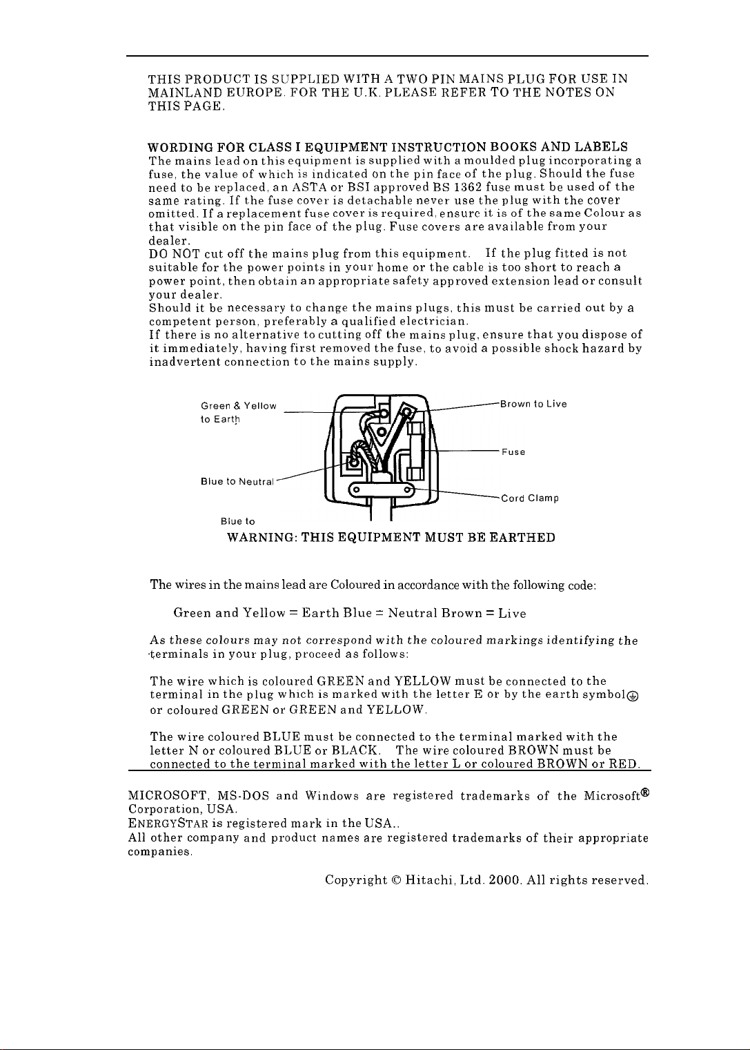
WORDING FOR CLASS I EQUIPMENT INSTRUCTION BOOKS AND LABELS
The mains lead
fuse, the value of which
need
to be
same rating. If the fuse cover
omitted. If a replacement fuse cover
that visible
dealer.
DO
NOT cut off
suitable for the power points in your home
power point, then obtain
your dealer.
Should
it be
competent person, preferably a qualified electrician.
If there
is no
it immediately, having first removed the fuse,
inadvertent connection to the mains supply.
on
replaced,
on the
the
necessary
alternative
this equipment
is
an
ASTA
pin face of
is
indicated
or
supplied with a moulded plug incorporating a
on the
BSI approved
is
detachable never use
is
the
required, ensure
plug. Fuse covers are available from your
pin face of the plug. Should the fuse
mains plug from this equipment.
or
an
appropriate safety approved extension lead
to
change the mains plugs, this must
to
cutting off the mains plug. ensure that you dispose of
to
BS
1362 fuse must
the
the cable
it is of
If
the
is
be
used of
plug with the cover
the same Colour as
plug fitted
too short
be
to
carried out
avoid a possible shock hazard
reach a
or
ON
is
consult
the
not
by
a
by
BE
Brown to Live
Cord Clamp
EARTHED
Green
&
to Earth
Blue to Neutral
Yellow
Blue to
WARNING: THIS EQUIPMENT MUST
IMPORTANT
The
wires
in the
mains
lead are Coloured in accordance
Green and Yellow
=
Earth Blue = Neutral Brown
As these colours may not correspond with the coloured markings identifying the
$erminals
The wire which
terminal
or
The wire coloured BLUE must
letter N
connected
MICROSOFT, MS-DOS and Windows
in
your plug, proceed
is
in
the plug which is marked with the letter E
coloured GREEN
or
coloured BLUE
to the
as
follows:
coloured GREEN and YELLOW must
or
GREEN and YELLOW.
be
or
connected
BLACK. The wire coloured BROWN must
to
terminal marked with the letter L
are
registered trademarks of
Corporation, USA.
ENERGYSTAR
All other company and product names
is
registered mark
in the
USA..
are
registered trademarks of their appropriate
companies.
with
the
following
=
Live
be
connected to the
or by the
code:
earth symbol@
the terminal marked with the
or
coloured BROWN
the
be
or
RED.
Microsoft@
Copyright 0 Hitachi, Ltd. 2000. All rights reserved.
Page 5

TCO’99 STATEMENT
Congratulations!
You have just purchased a
with a product developed
burden on
electronics products.
This product meets the requirements for the
environmental and
as a
Naturskyddsforeningen
Energimyndighet (The Swedish National Energy
the
environment and also to
joint
effort by the TCO (The Swedish Confederation of
TC0’99
for
quality labelling of
(The
approved and labelled product! Your choice has provided you
professional use. Your purchase has also contributed to reducing the
Swedish Society for Nature Conservation), Statens
the
further development of environmentally adapted
TC0’99
personal computers. The
scheme which provides for an
Administration)
labelling
Professional
and SEMKO AB.
scheme was developed
Employees), Svenska
international
The requirements cover a wide range of issues: environment, ergonomics, usability, reduction
electric and magnetic fields, energy consumption and electrical safety.
Why do we have environmentally
In many countries,
the adaptation of goods and services to the environment. The main problem, as far as computers
and other electronics equipment
used both in the products and during their manufacture. Since it is
satisfactorily recycle the
majority of electronics equipment, most of these potentially damaging substances sooner or later
enter nature.
There
are
that
environments. Since all methods of electricity generation have a negative effect on the
environment
save energy. Electronics equipment in offices is often left running continuously and thereby
consumes a
also other characteristics of a computer. such
are
important from the viewpoints of both the work (internal)
lot of
environmental labelling
(e.g. acidic and climate-influencing
energy.
labelled
are
computers?
has become an established method for encouraging
concerned, is that environmentally harmful
emissions, radioactive waste), it is
not so
as
energy consumption levels,
substances are
far possible to
and natural (external)
vital to
What does the environmenal labelling involve?
The environmental demands has been developed
(The Swedish
presence and use of heavy metals, brominated and chlorinated flame retardants, CFCs
(freons) and chlorinated solvents, among other things. The product must
for recycling and the manufacturer is obliged to have
must
be
policy.
The energy requirements include a demand that the computer and/or display,
certain period of inactivity, shall reduce its power consumption to a
stages.
Society for Nature Conservation).
adhered
The length
to in
each country where the company implements its operational
oftime
to
reactivate the computer shall
by
These demands impose restrictions on the
Svenska Naturskyddsforeningen
be
an
environmental policy which
lower level in one or more
be
reasonable for the user.
prepared
after
a
cf
Page 6
Below you will find a brief summary of the environmental requirements met by
this product. The complete environmental criteria document may be ordered from:
TCO Development
SE-114
94
Fax: +46 8 782
Email (Internet): developmentQtco.se
Current information regarding TC0’99 approved and labelled products may
also
be
obtained via the Internet, using the address: http://www.tco-info.com/
Stockholm, Sweden
92 07
Environmental requirements
Flame retardants
Flame retardants
Their purpose is to prevent, or at least to delay the spread of
computer casing can consist of flame retardant substances. Most flame retardants contain
bromine or chloride, and those flame retardants
environmental toxins, PCBs. Both
PCBs
are
fish-eating birds and mammals,
been found in human blood and researchers fear that disturbances in foetus development may
occur.
The relevant TCO’SS demand requires that
must
retardants
suspected of giving rise to severe health effects, including reproductive damage in
not
contain flame retardants with organically bound bromine or chlorine. Flame
are
allowed in
are
present in printed circuit boards, cables, wires, casings and housings.
are
the
flame retardants containing bromine or chloride and
due to the
the
printed circuit boards since no substitutes
bio-accumulative processes. Flame retardants have
chemically related to another group
plastic
components weighing more than 25 grams
fire. Up to
30% of
are
available.
the
plastic in
a
of
the
Cadmium
Cadmium is present in rechargeable batteries and in
computer displays. Cadmium damages
relevant
screens and the electrical or electronics components must not contain any cadmium.
TC0’99
requirement states that batteries,
the
nervous system and is toxic in high doses. The
the
colour-generating layers of certain
the
colour-generating layers of display
Mercury
Mercury is sometimes found in batteries, relays and switches. It damages the nervous system
and is toxic in high doses. The relevant
contain
electronics components associated with the labelled unit. There is however one exception.
Mercury
today is no commercially available alternative. TCO aims on removing this exception when
mercury free alternative is available.
CFCs (freons)
The relevant
manufacture and assembly of
circuit boards. CFCs break down ozone and thereby damage the ozone layer in the stratosphere,
causing increased reception on earth of ultraviolet light with
(malignant melanoma) as a consequence.
any
mercury. It also demands that mercury is
is,
for the time being, permitted in
TC0’99
requirement states that neither CFCs nor HCFCs may be used during
the
TCO’SS
requirement states that batteries may not
not
the
back light system of flat panel monitors as there
product. CFCs (freons)
present in any of
are
sometimes used for washing printed
e.g.
increased risks of skin cancer
the
electrical or
a
the
Lead
Lead can be found in picture tubes, display screens, solders and capacitors. Lead damages the
nervous system and in higher doses, causes lead poisoning. The relevant TCO’SS requirement
permits
the inclusion of lead since no replacement has yet been developed.
Page 7
Model
CMLl5lXW
User’s Manual
Thank you for purchasing Hitachi’s Liquid Color Display.
Please read
guarantee.
l
. Please keep this User’s Manual in a handy location for easy reference.
the
User’s Manual carefully and store in a safe place along witfi the
Please read and make sure you fully understand the safety precautions
before use.
Page 8

Page 9
Contents
A
!Usine
Forward
......................................................................................................
ICheckllst
B
Routine
.......................................................................................................................
Cal-e
................................................................................................................
t Features .........................................................................................................
......................................
H
to&PC
Connectjon Procedure
m
PC Setup..
m
Recommendations on use of Human
I
B
@
1
Pow62 Switch
Power
Lxmg
OSD
Operation Button ..............................................................................................
......................................................................................
.................................................................................................
.....................................................................................................................
of
Pa&La
.............................................................................................................
................................
..............................................
.
I Summalv of Adjust
.
OSD Adudment
-
@ meous
ware
Technical
E Snecificat’
m
Connector
‘,.m
Function
ent
$
Functions
.............................................................................................................
Ions
Sip&
....................................................................................................
..................................................................................
.......................................................................................
m
Possible Causes
1
When
you
and
don’t know what to do
...................................................................................................
alltee and
B
a
...............................
Displa!r
Placement..
JVliscelJ.aneous..
Servicinv ........................................................................................
...................................................................................................
...........................................................................................................
.......................................
Eneineered Disolay
......................................
...................................................................
...............................................................................
................................................
Functions
......................................................................................
s
.........................................................................
...........................................................................................
...............................................................
..............................................................................
.................................................................................
..............................................................................
.................................................................
.._
2
6
6
6
7
8
8
9
10
11
12
12
12
13
14
15
25
26
26
..2 7
..2 8
29
30
30
30
31
..3 1
32
32
32
.
Page 10
L 0
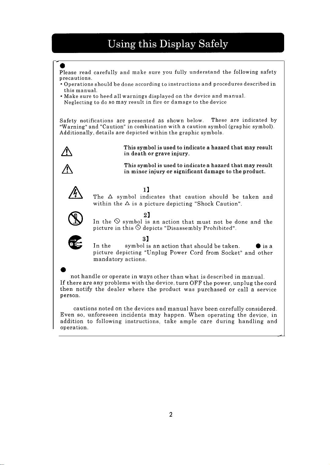
Common Safety Precautions
Please read carefully and make sure
precautions.
* Operations should
this manual.
- Make sure
Neglecting
l
Symbols
Safety notifications
“Warning” and “Caution”
Additionally, details are depicted within
to
to do so
be
done according
heed all warnings displayed
may result in fire
are
presented
in
combination with a caution symbol (graphic symbol).
you
fully understand
to
instructions and procedures described in
or
as
shown below.
the
on the
damage
device and manual.
to
the device
graphic symbols.
the
These
following safety
are
indicated by
! WARNING
n
! CAUTION
n
This symbol is used
in death
This symbol
in minor injury or significant damage to the product.
or
grave injury.
is
to
indicate a hazard that may result
used to indicate a hazard that may result
[Notice Example 11 Shock Caution
A
The A symbol indicates that caution should be taken and
within the A is a picture depicting “Shock Caution”.
[Notice Example ~1 Disassembly Prohibited
CD
In the 8 symbol is an action that must not be done and the
picture in this 8 depicts “Disassembly Prohibited”.
[Notice Example 31 Unplug Power Cord from Socket
In the
l
e
0
Handling and Operation
DO
not handle
If there are any problems with the device, turn OFF the power, unplug the cord
then notify the dealer where the product was purchased
person.
picture depicting “Unplug Power Cord from Socket” and other
mandatory actions.
or
symbol is an action that should be taken.
operate in ways other than what is described in manual.
This
or
call a service
0
is a
l Taking ample care
The
cautions noted on the devices and manual have been carefully considered.
Even so, unforeseen incidents may happen. When operating the device, in
addition to following instructions,
operation.
take ample care during handling and
2
Page 11
Using this Product Safely
Points of Caution
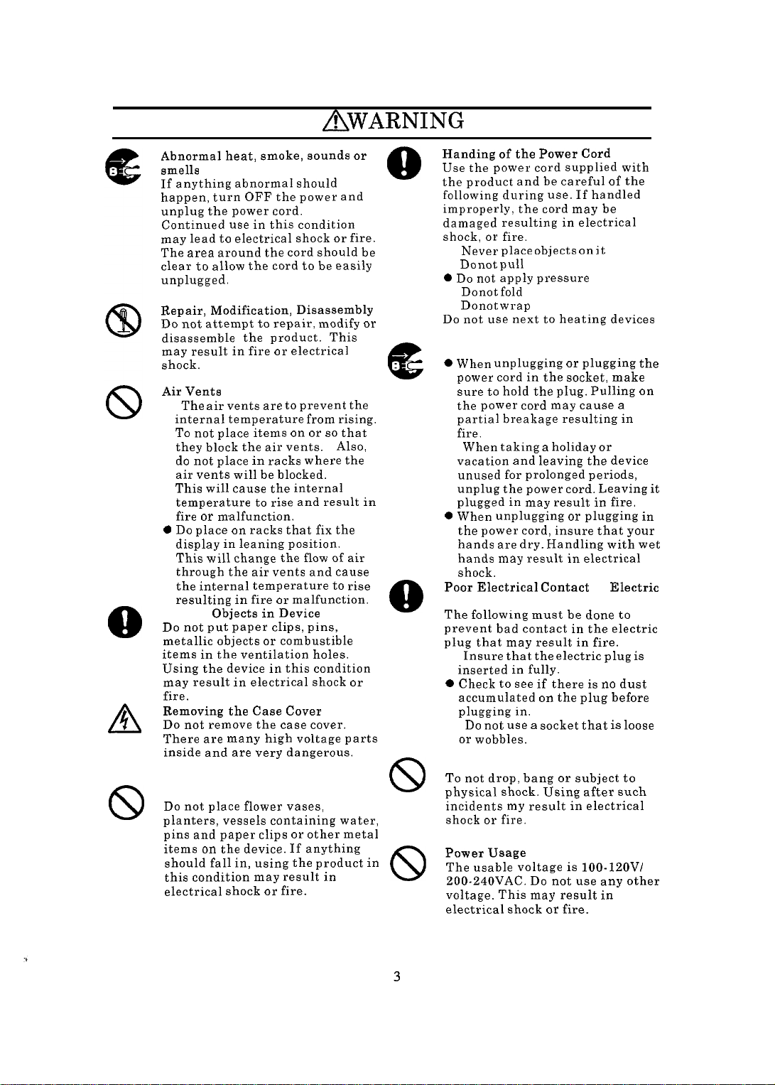
AWARNING
8
A
8
Abnormal heat, smoke, sounds or
smells
If anything abnormal should
happen, turn OFF the power and
unplug the power cord.
Continued use in this condition
may lead
The
clear to allow the cord to
unplugged.
Repair, Modification, Disassembly
Do not attempt
disassemble
may result in fire
shock.
Air Vents
l
0
Do
Placing
Do
metallic objects
items in the ventilation holes.
Using the device in this condition
may result in electrical shock
fire.
Removing the Case Cover
Do
There
inside and
Placing Objects on the Device
Do
planters, vessels containing water,
pins and paper clips
items
should fall in, using
this condition may result in
electrical shock
to
area around
The air vents
internal temperature from rising.
To
they block
do not
air vents will
This will cause the internal
temperature
fire
display
This will change the
through
the
resulting in fire
not put paper clips, pins,
not remove the case cover.
not place flower vases,
electrical shock
the
to
repair, modify
the
product. This
or
are to
not place items
or
the
place in racks where
malfunction.
place
on
in
leaning position.
the
internal temperature
Objects in Device
are
many high voltage parts
are
on
the device. If anything
on or so
air vents.
be
blocked.
to
rise and result in
racks that fix
air vents and cause
or
or
combustible
very dangerous.
or
or
fire.
or
cord should
be
easily
electrical
prevent
Also,
the
flow of
to
malfunction.
other metal
the
product
fire.
be
the
that
the
air
rise
or
or
in
0
e
a
8
8
Handing of the Power Cord
Use
the
the product and
following during use. If handled
improperly, the cord may be
damaged resulting in electrical
shock,
l
l
0
Do not
l Do not
l Do not
Do
Plugging and Unplugging
0 When unplugging
l
0 When unplugging
Poor Electrical Contact
Plug, etc.,
The following must be done to
prevent bad contact in the electric
plug that may result in fire.
l
0 Check
l Do
Impact from Dropping
To not
physical shock. Using after such
incidents
shock
Power Usage
The usable voltage is 100-lZOV/
ZOO-240VAC. Do
voltage. This may result in
electrical shock
power cord supplied with
or
Never place objects
Do not pull
not use next
power cord in
sure
to
the
power cord
partial breakage resulting in
fire.
When taking a holiday
vacation and leaving the device
unused for prolonged periods,
unplug
plugged in may result in fire.
the
power cord, insure that your
hands
are dry.
hands
may
shock.
Insure that
inserted in fully.
to see if
accumulated
plugging
not use a socket that
or
wobbles.
drop, bang
or
be
careful of the
fire.
apply pressure
fold
wrap
hold
the
the
power cord. Leaving
result in electrical
the
in.
my
result
fire.
on it
to
heating devices
or
the
socket, make
plug. Pulling
may
or
Handling with wet
electric plug
there
on the
or
subject to
in
not use any other
or
fire.
plugging the
cause a
or
plugging in
in
Electric
is no
dust
plug before
is
loose
electrical
is
on
it
3
Page 12

Using this Product Safely
AWARNING
Points of Caution
Handling the
l Do not
hands. This
electrical shock.
l Do not use
this display. This
shock, fire.
device.
0
Do not use or
heat accumulates. This
in
fire.
Multi-Tap Usage
To
not attach multiple extension
plugs into
result
in
will activate
causing data loss
product.
AC
wet
one
fire and overloading line
adapter
or
handle with
may
result
with devices other than
may
or
damage
place
outlet.
the
circuit breakers
or
damage
in
result
to the
in
areas where
may
This
wet
in
result
may
to
the
Usage in Humid or Dusty Areas
Do
not
use or
humid, dusty
moisture such
may
cause fire
store in areas that
or
have abundant
as a
bathroom.
or
electrical shock.
This
Moving to Areas of Different
Temperature
Moving the device to areas that
very different in temperature may
cause condensation
and internally. Using
this condition may result
electrical shock. Leave
at
the location for a
using.
on the
the
the
few
hours before
outside
device
in
are
fire
device
are
in
or
Damage
8
l
l
to the
Liquid may leak out of
when damaged.
liquid. If you should touch
liqutd, wash your hands
thoroughly with water. If
liquid should
or
eyes, gargle
and promptly
treatment.
The display unit
If
the
avoid handling the glass
fragments. The fragments
dangerous and can cause injury.
Display Unit
Do not
get
or
see a
display unit should break,
the
display
touch
the
the
into your mouth
rise your eyes
is
the
doctor for
made of glass.
are
Aluminum Electrolysis Condenser
The electrolyte condenser used in
the
AC
adapter has a limited life. If
used past the life span
(approximately 5 years), replace the
AC
adapter. Leakage
the
electrolyte liquid
fire
or
electrical shock. This may
also cause
malfunction
the
or
may
device itself
drying
result in
to
up
of
4
Page 13
Using this Product Safely
Points of Caution
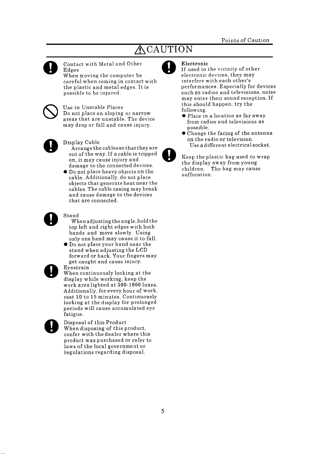
&~~uTION
8
8
8
a
8
8
Contact
Edges
When m
careful when coming in contact with
the plastic and metal edges.
possible
Use in Unstable Places
Do not
areas that
may drop or
Display Cable
l
0
Do not
Stand
l
0
Do not
Eyestrain
When continuously looking
display while working, keep
work area lighted
Additionally, for every hour of work,
rest 10 to 15 minutes. Continuously
looking
periods will cause accumulated
fatigue.
Disposal of this Product
When disposing of this product,
confer with the dealer where this
product was purchased
laws of the local government
regulations regarding disposal.
with Metal and Other
.oving
the
computer
to be
injured.
place
on
sloping
are
unstable. The device
fall and cause injury.
Arrange
out of
on, it
damage
cable. Additionally,
objects that generate heat near
cables. The cable casing may break
and cause damage
that
When adjusting the angle, hold
top
hands and
only
stand when adjusting
forward
get
the
the
may cause injury and
are
left and right edges with both
one
caught and cause injury.
at the
cables
way. If a cable
to
the connected devices.
place heavy objects
connected.
move
hand may cause
place your hand near the
or
to
slowly. Using
back. Your fingers may
at
display for prolonged
be
It is
or
narrow
so
that they
do not
the devices
the LCD
300-1000 luxes.
or
is
tripped
on the
place
it to
at
the
refer
or
are
the
the
fall.
the
eye
to
Electronic
If used
electronic devices, they may
interfere with each other’s
performances. Especially for devices
such
may enter their sound reception. If
this should happen,
following.
0 Place in a location
from radios and televisions
possible.
0 Change
on
l Use
Storing the plastic bag
Keep the
the display away from young
children.
suffocation.
Interference
in the
as
the radio
vicinity of other
radios and televisions, noise
try
the
as
far away
the
facing of
or
a different electrical socket.
plastic bag used to wrap
The bag may cause
the
television.
as
antenna
5
Page 14

Forward
Thank you for purchasing Hitachi’s color LCD monitor. (To be referred to as display
from hereon)
This product is a high precision detail liquid crystal display capable of displaying up
to 1024 x 768 dots.
Additionally, read the manuals that came with the video cards and personal
computer (To be referred to as PC from hereon) to be connected (including
restrictions).
W
Checklist
Please confirm the following before use.
If there are any discrepancies, contact your dealer.
0 Is this the model you ordered?
l Is there any damage from shipping?
0 Were the following items included?
n Display
n Display cable
n Power cord
n
User’s manual (this book)
H
Warranty registration card
n AC adapter
n Routine Care
l Before doing any maintenance of the display, insure that the power is OFF.
0 Wipe any dirt off with a dry soft cloth. If soiled with oil or heavily soiled, damp
cloth with water or soap, wring dry and lightly wipe the soiled areas. Remove
dust with a vacuum cleaner or a dry cloth. If water or soap should get into the
display, this may cause damage.
0 Using benzene or thinner on the display or contact with insect spray may deform
or discolor the display.
0 The surface of the LCD scratches easily and nothing hard (pencil lead hardness of
HB or harder) should be pressed or rubbed against it. Even tissue paper can
scratch the display if rubbed too hard and therefore caution should be taken.
If the LCD surface becomes dirty, wipe lightly with a soft dry cloth.
If the surface is difficult to clean, use a small amount commercial LCD cleaner
and wipe clean. Make sure that the cleaner does not drip inside of the display.
Read this manual carefully to use the display properly.
Page 15

W
Product Features
The following features are available.
In addition to manual adjustments, position and other screen status can be
automatically adjusted. Also fine adjustments for brightness, color balance,
and contrast can be made easily while looking at the screen menu.
The maximum resolution is 1024 x 768 pixels.
It is also possible to magnify
and display in 640 X 480 pixel and 800 x 600 pixel modes.
Full color (16.77 million colors) display is supported and can be used in a wide
range of applications from still screens to moving pictures.
The interface to the PC is compatible with an analog CRT interface and can be
readily used just by connecting to the PC CRT display connector.
DDCBB
is supported and is Plug & Play compatible.
Also
Power consumption is approximately 35W and compared to a 17-inch CRT
monitor is highly energy efficient.
\
Additionally, DPMS (Display Power Management Signaling) is supported and
is
EnergyStar
The required setup space is also about half of a
compliant.
l7-inch
CRT display.
Page 16

Connecting
to a PC
n Connection Procedure
Check to see that all power switches are set to OFF before continuing. The display
power switch will be OFF when the yellow power lamp is not lit. For the location of
the power switch, please refer to
Please also refer to the manual that came with the PC.
Display
“Names and Operation of Parts”.
/
Power cord
DC plug
Power connector
Display cable connector
+ To Personal
Computer
J[x
Power plug
+ To AC outlet
AWARNING
0 Hold the power plug firmly whenever plugging in or unplugging the power cord
from the AC adapter and the wall socket.
pushed all the way in.
l Do not voltage other than shown (100-12OV/200-24OV AC).
l Do not use power cords other than the one provided with the product.
Also make sure that the plug is
+F
Supplement
0 Turn the 2 knobs to the right to firmly secure the display cable.
l Connect the display cable directly to the PC and do not use extension cables.
8
J
Page 17

n PC Setup
When the screen is displayed use the OSD (On Screen Display) functions (refer to
“Adjustments”) and adjust to the best display settings.
When changing the display mode, confirm that the mode is supported by this
display. (Refer to “Video Modes”)
This is the procedure for Windows 98.
version of Windows is being used.
the screen.
Start up Windows
1.
2.
Click [Start], [Setting (S)], and [Control Panel(C)] in this order.
Double click [Display] in the [Control Panel].
3.
Click the [Settings] tab.
4.
Set the “Display fields”, “Color pallets”, etc.
5.
6.
Click on [Details (D)...].
7.
Click on the [Monitor] tab.
Check on “Automatically detect Plug & Play monitor (P)” in Options.
8.
Refer the manual included with the PC to set the refresh rate.
9.
10.
Click the m button.
The procedure may differ according to what
If this should happen, follow the instructions on
-
A
E
Page 18

n Recommendations on use of Human Engineered
Insure that no hght from flstures
or wmdows reflect off screen
that no light from fixtures or
wndows
reflect off screen.
sure
hlXE3)
Adjustable back
Low arm rests
Display-
and lap
Feet should reach
floor
use a platform or
step if feet cannot
reach floor
comfortably.
Appropnately soft with ample
airflow
Posture adjustable rotating seat
Casters to adjust dmtance from
PC (5 legs or more
1
Reference: Japan Human Engineering Association notebook PC usage Human
Engineering Guidelines.
l Set the PC display in front of you and adjust to an easy viewing angle.
l The illumination and brightness of the display should be adjusted appropriately
(1988
Labor Science Research Institute)
to the surrounding lighting and suppress reflection from the display.
l Adjust the brightness and contrast for easy viewing.
l The keyboard and mouse should be placed level with your wrists.
l Work on the PC should be limited to a maximum of 6 hours and a
lo-15
minute
break should be taken every hour.
l The keyboard should be set to an easy to use angle.
l Insure ample workspace even when connecting peripherals.
l Avoid unnatural posture and change postures occasionally.
10
Page 19

Names
The display can be adjusted up 30 degrees and down 5 degrees. Also it can be rotated
60 degrees left and right. Choose an angle that is most suitable for you.
and
Oneration of
Parts
ACAUTION
0 When adjusting the angle, hold the top left and right edges with both hands and
move slowly. Using only one hand may cause it to fall.
l Do not place your hand near the stand when adjusting the LCD stand forward or
back. Your fingers may get caught and cause injury.
11
Page 20
n Power Switch
l Pressing switch will turn the power ON. Press the switch again to turn off the
power.
When the power is turned ON, the POWER lamp will light green.
l It will take 20-30 seconds for the display to stabilize after turning on the power.
The back light may flicker during this time.
l Wait at least 30 seconds before turning on the display again after turning it off.
n Power Lamp
l
Green
This will light when the power is on.
on.
0 Orange
This indicates that the power is on.
function is in operation.
Nothing will be lit when the power is not
This will light with the energy saving
n OSD Operation Button
The buttons are used in the following manner.
for details.
Refer to the adjustment functions
+ MENU button
0
When the OSD is not being displayed, pressing this will display the OSD
menu.
0 This is used with the OSD menu displayed to select various settings.
0 If pressed for about 2 seconds when the OSD menu is being displayed, the
OSD display will end.
4
UP
button (A display)
0
This will move the cursor up,
according to the menu. Holding down this button will continuously increase
adjustments.
0
If pressed when the OSD menu is not being displayed, the brightness
adjustment bar will be shown.
+ DOWN button (V display)
0
This will move the cursor up, to the left or decrease an adjustment according
to the menu. Holding down this button will continuously increase
adjustments.
0
If pressed when the OSD menu is not being displayed, the automatic setting
menu will be shown.
to the right or increase an adjustment
12
Page 21

Adjustments
The video signal that is input will differ even in same display modes according to
the PC output. When connected to the PC for the first time, the display position
may be offset or the dots may appear distorted. Before use, adjust the screen
display.
Pressing the DOWN button
automatic settings according to the menu.
If you wish to manually adjust each setting or adjust other settings, use the
functions. Make the adjustments with the buttons while looking at the OSD menu.
l If a video signal is not input from the PC, the adjustment functions will not
operate.
0 Please refer to the manual supplied with the PC for display settings on the PC
side.
l The brightness, display color, OSD position adjustments, and language setting
are common to all display modes.
All other settings are only valid for current mode and when the display mode is
changed, those settings must be redone for each mode.
Display modes that have close frequencies may be recognized as the same
mode.
9 The display may not be appropriately set with the automatic settings because
of differences in the PC input signals.
this should happen.
(V)
will display the automatic setting menu.
Use manual settings for fine-tuning if
Make the
-~
A
E
13
Page 22

n Summary of Adjustment Functions
The following can be adjusted with the OSD functions.
vbutton
Abutton ---+
MENU
button
-
Horizontal/Vertical position, Phase, Clock, Contrast,
and Color Balance adjustments are
to the best settings.
Adjusts brightness of backlight.
Adjusts
for the display.
Adjusts vertical position for
the
&splay.
Adjusts color differential to
approximate
Adjusts color balance.
Adjusts individual brightness
of RGB.
Adjusts individual standard
levels for RGB (offset values).
Horizontal/Vertical position, Phase,
Clock, Contrast, and Color Balance
adjustments are automatically set.
Adjusts the number of dot clock
numbers in one horizontal period.
automatically
horizontal
LCD or CRT.
set
position
14
Adjusts sampling timing for
input display data.
Displays input signal
information
Adjusts OSD display
position
Sharpens image
Selects OSD display language
Clears set data and restores
factory settings.
Page 23

H
OSD Adjustment Functions
The screen may not display properly because of inconsistencies in display timings
according to the PC being used. This display has an automatic adjustment function
that will allow adjustments of the screen.
If the automatic adjustment cannot
properly adjust the settings or set the color balance to your preference, settings can
be done manually.
The Japanese display mode will be explained here.
ORecommended Adjustment Screen
Before using the automatic adjustment function, display the recommended screen
shown below. If a screen other than the recommended one is used, the adjustment
may not be carried out properly.
Start up Explorer and display the window full screen. Click the q button located on
the upper right of the screen with the mouse.
Recommend Screen Example
15
Page 24

1. Automatic Setting
When the screen is being displayed and the OSD window is not being displayed and
the DOWN
(V)
button is pressed, the OSD menu will be shown. Move the cursor to
“Yes” and pressing the Menu button will automatically adjust the clock, phase,
horizontal position, and display color.
l The automatic adjustments may fail because of the screen displayed or device
connected. When this happens, change the screen and try again.
l The automatic adjustments may fail to completely suppress flicker on the
screen. When this happens,
save the settings and from the OSD menu,
manually adjust using the Phase adjustment. However, screen flicker or blurry
text may result from change in the surrounding temperature. If this happens,
redo the setting.
l The automatic adjustment may fail to properly adjust the screen depending on
the PC connected. If this should happen, adjust manually.
When automatic settings are completed the OSD menu will appear to allow you to
save the settings or restore the previous settings.
16
Page 25

2. Main Menu (Manual Adjustments)
When the MENU button is pressed with the screen being displayed without the OSD
menu showing, the following OSD menu will be displayed. Pressing the menu button
will move the cursor to the next item to adjust.
The icon at the cursor position will change form blue to red and name of the
adjustment will be shown.
After moving through (1) - (6), the OSD menu will end if the MENU button is
pressed.
Adjustments
(1) Brightness (2) Contrast (3) Display position (4) Display color
(5) Clock/Phase (6) Management
The OSD menu will automatically end if there is no operation for about 30
seconds.
Press the MENU button for about 2 seconds to end the OSD menu.
(1) Brightness adjustment
Select with the MENU button or press the A button with the OSD menu not being
shown to display the brightness adjustment screen. When the A button is pressed,
only the brightness adjustment bar will be shown.
This adjusts the brightness for the backlight.
A
E
Brightness
(2) Contrast adjustment
This adjusts the ratio of the white and black levels.
will differ according to the PC.
17
brightness
The adjustment value range
Button Operation
A : Increase value
V:
Decrease
~
value ~‘::i
,)
Page 26

(3) Display position adjustment
This adjusts the position of the screen display.
Selecting “Return” will move to the following “Display Color Adjustment” menu.
?
I. _
Display
l
Horizontal position adjustment
Adjust the horizontal position of the screen while looking at the display screen.
H.Position
-I+
l
Vertical position adjustment
Adjust the vertical position of the screen while looking at the display screen.
V.Position
--(+
I
I
I
1
J
Button Operation
A ‘I : Move cursor
(UP,
MENU: Set
3utton Operation
I:
,
Ir:
Right
I: Left
V:
Down
II
I I
down)
I
(4) Display color
Adjusts the display screen color.
Selecting “Return” will move to the following “Clock/Phase Adjustment” menu.
18
Page 27

a
Gamma Correction
Adjusts color differential to approximate LCD or CRT.
0
Color Balance
Accents the screens reds and blues.
l
RGB Adjust
Adjusts the brightness of RGB (Red, Green, Blue) in
When “Return”
Adjustment” menu.
is selected, you will return to
1
(UP, down)
I
detail.
the previous “Display Color
I
The following menu is shown when a color is selected.
when red is selected.
I
! Restriction
0 Color balance should be done after contrast adjustments are completed.
19
The following screen is
Page 28

@Black
This adjusts the standard levels of individual RGB colors.
When “Return”
Adjustment” menu.
Level Adjustment
is selected, you will return to the previous
“Display Color
Black Level Adiust
The following menu will be shown as each color is selected. (The following is when G
is selected)
I
Q cc) Q
Green
-I+
EHzMEl
Button Operation
A V:
Move cursor
(up, down) .
1
MENU: Set
I
Button Operation
A: Raises the
standard level of
color selected
V:
Lowers the
standard level of
color selected
1
MENU: Set
! Restriction
0 The black level should be adjusted after the contrast adjustments are completed.
(5) Clock/Phase Adjustment
Adjusts the number of dot clocks within a horizontal synch.
Adjusts the sampling timing for the input display data.
When “Return” is selected, you will move the following “Management” menu.
I
20
Button- Operation
MENU: Set
Page 29

l
Automatic Settings
This is the same as when the DOWN button (‘I) is pressed when the OSD menu is
not being displayed.
Please refer to
“1.
Automatic Settings” for details.
E
OClock
horizontal synch. If the clock is not adjusted properly the screen will
drift or vertical stripes may be generated according to the screen
being displayed.
is drifting or with the vertical stripes being displayed.
Screen Drift
Adjustment Adjusts the number of dot clocks within one
If this happens, adjust the clock while the screen
Clock
-I+
I
Vertical Stripes Example
v:
Decrease value
I I
I
21
Page 30

l
Phase Adjustment
This will make fine adjustments for the phase of the display data and
dot clock. This adjustment is used when the text appears blurry or
the screen flickers.
result after adjustments due to the surrounding temperature.
However, display flicker and text blur may
When
this happens, redo the adjustments.
Before doing this adjustment, complete “a Clock Adjustment” first.
I
Q Q Q
Phase
F3ElEl
Button Operation
V
: Decrease value
Example of blurred text
ABCDEFGHIJKLMNOPQRST
UVWXYZ
ABCDEFGHIJKLMNOPQRST
UVWXYZ
Example of screen flicker
.
.~.‘.‘.~.‘.‘.~.~.‘.~.‘.‘.‘.~.‘.‘.~.’.’.’.~.’.~.‘.‘.‘.‘.‘.’.’.’.’.‘.‘.‘.‘.‘.‘.‘.‘.‘.‘.‘.’
. . . . . . . . . . . . . . . . . . . . . .
.‘.~.‘.‘.‘.~_‘.‘.‘.‘.‘.‘.‘.‘.‘.‘.’.’.’.’.’.’.’.‘.‘.‘.‘.‘.’.’.’.’,‘.~.‘.‘.‘.‘.‘,‘.~.‘.‘.’
.‘.‘.‘.‘.‘.‘.‘.‘,‘.‘.‘.‘.‘.‘.‘.‘.’.’.’.’,’.’,’.‘.‘,‘.‘,‘,’,’.’.’,‘.~.‘.‘.‘.‘,‘.‘,‘.~.~.~
.‘.‘,‘.‘_‘.‘_‘,‘.‘,‘,‘,‘,‘.‘.‘.‘.’.’.’,’,’.’,’.~.‘,‘.‘,‘,’,’.’.~,~.~.~.‘.~.~.~,~.~.~.~.~
. . . . . . . . . . . . . . . . . . . . . . . . . . .
‘.‘.‘.‘.‘.‘.‘.‘.‘.‘.‘.‘.‘,‘.‘.‘.’.’,’.’.’.’.’.’.~.‘.‘.‘,‘,’,’.’.~.‘.‘.~,~,~.~,~.~.~,~.~.
. . . . . . . . . . . . . . . . . . . . . . . . . .
.‘.‘.‘.‘_‘_‘,‘.‘_‘.‘,‘.‘,‘,‘.‘.‘.~.’.~,’,’,~,~.~.~,~.~,~,~.~.~.~.~.~.~.~.~.~.~.~.~.~.~.~
.‘.‘.‘.‘_‘_~_‘.~_~.‘.‘.‘.‘.~.‘.~.~.’.~.’.~.~,~.~.~,~.~,~,’,’,~.~,~.~,~.~,~.~.~.~.~.~.~.~
_‘.‘.‘.‘.‘_‘_‘.‘_‘_‘.‘.‘.‘.‘.‘.‘.’.’.’.’.’.’.’.~.‘,‘.~,~.~,’,~.~,~.~.~.~,‘.~.~,~.~.~.~.~
_‘.‘.‘.‘.‘_‘_‘.‘_~_‘.‘.‘.‘.‘.‘.‘.’.’.~.’,’.’,~.~.‘,~.‘,~,~,’,~.~,~.~,~.‘,~,‘.~,~.~.~.~.~
. . . . . . . . . . . . . . . . . . . . . . . . .
. . . . . . . . . . . . . . . . . . . . . . .
. . . . . . . . . . . . . . . . . . . . . . . . . . .
‘_‘.‘_‘,‘_‘_‘.‘_‘_‘.‘,‘.‘,‘.‘,‘.’.’,’.’,’,’,’.’.‘,‘.~,‘.~.’,~.’.~.~.~.~.~,~,~.~.~.~.~.~,
. . . . . . . . . . . . . . . . . . . . . . . . .
. . . . . . . . . . . . . . . . . . . . . . . . . .
. . . . . . . . . . . . . . . . . . . . . . . . . . .
.
22
Page 31

(6) Management
Displays input signal information.
Selects OSD display position/display language.
Sharpens image.
Clears settings and restores factory settings.
When “Return” is selected, the OSD menu will end.
A V : Move cursor
0
Display Mode Information
Displays the input signal resolution, horizontal sync frequency, and vertical sync
frequency.
l OSD Position Adjustment
Changes the OSD display position.
When “Return” is selected, you will return to the previous “Management” menu.
When the horizontal position adjustment is selected, the following screen will be
shown.
Adjust the screen horizontal position while looking at the display screen.
Q Q Q HtTAcHl CJ El m
H.Position
-
The same procedure is used to adjust the vertical position.
+
A: Move right (up)
V : Move left
$Aow& i
23
Page 32

0
Sharpness
This will sharpen or blur images.
“Low” is useful for displaying photos.
“Smart Sharpening” will more clearly display outlines than
“medium” for windows and similar images.
However, this function may cause flicker depending on the
screen being displayed and the PC connected.
Adjust the setting to your preference while looking at the
display screen.
0
OSD Language Selection
Selects the language for the OSD menu display.
A
: Move up
I: Move down
V:
Move down
0
Clear All Settings
Returns saved settings to factory settings.
Button Operation
A V
: Move cursor
1
MENU: Set
I
24
Page 33

H
Miscellaneous Functions
0 Energy Saving Function
(VESA DPMS Function: Video Electronic Standard Association Display Power
Management Signaling)
If the display does not receive a video signal and a sync signal, it will
automatically decrease power consumption and the SAVE lamp located on the
right side of the screen will light orange. To use the PC energy saving functions,
refer to the manual that came with the PC.
l
Plug & Play Function
This device supports DDC2B (Display Data Channel 2B) standards and is Plug
Play compliant. Refer to the PC manual when connecting to a PC and using the
Plug & Play function.
E
&
2.5
Page 34

Hardware
W
Specifications
Technical
Information
LCD
Input signal
Input terminal
Resolution
Display size
Display colors
Brightness
Contrast
Adjustments
Power management
Plug&Play
15.0 inch TFT
Pixel pitch 0.297mm
Drive method: Active matrix TFT
Viewing angle: Up 45” , down 55” left - right 120”
Video 0.7 Vp-p, 75R
Synchronized TTL level separate composite sync.
Analog RGB Interface D-Sub 15P
Horizontal max. 1024 dots
Vertical max. 768 dots
Horizontal 304.1 mm
Vertical 228.1 mm
16.77 million
200cd/m2
35O:l
OSD functions (brightness, contrast, display position
setting, display color, clock/phase, and management)
VESA DPMS
VESA
DDCBB
Operating Environment Temperature 5
Humidity 20 - 80% Rh or less (no condensation)
Max. dry heat temperature
Power
Power consumption
Dimensions
Weight
AC lOO-12OV/200-240V AC
Approx. 35W
5W
or less (in energy saving mode)
374(H)
Approx. 5.2kg (Excluding AC adapter, display cable, and
power cord)
x377(W) X
-
35°C
220(D)mm
26
25°C
Page 35

W
Connector Signals
l
15
pin mini D-SUB connector
13
1
HSYNC
14
1
VSYNC
1
15 1SCL ‘1
*l
This signal is valid for DDC2B compatible PCs
Chart from display connector
1
Horizontal Sync Signal
1
Vertical Sync Signal
DDC Clock
1
Input
1
Input
)
Input
1
27
Page 36

n Video Mode
Set your PC video mode to the following appropriate setting.
Refer to the manual that came with the PC for setting procedures.
“1:
The horizontal sync frequency is sometimes referred to as the refresh rate.
“2: Item 12 (1024 X 768(VESA), vertical sync frequency 60Hz) display mode is
recommended.
0 If the display does not properly display the screen due to timing inconsistencies,
use the OSD functions to adjust.
l Confirm beforehand that the display mode is compatible to the video modes
listed above when changing the PC resolution and color settings.
If set to a video mode not listed above, the screen may become distorted or not
display properly.
0 Also, if set to a video mode not listed above and even when the display appears
normal, the OSD adjustments may not function properly.
l If connected to a notebook computer and used with the built-in display, the
display may work properly according to the computer.
However, only the
externally connected monitor will display.
0 Modes other than 1028 x 768 may have text appear unclear.
This is because the
text is being virtually enlarged and is not a malfunction.
0 When switching between display modes, noise may appear on the screen, this is
not a malfunction.
28
Page 37

The LCD parts will get worn and wear out as they are being used.
Replace the following parts when their life expires.
Contact your dealer when this becomes necessary.
The replacement parts may differ from the original parts.
LCD Module (LCD)
AC Adapter
Display Control Board
“1: The life span of each part is about 5 years. This is calculated on normal use in
an office environment with standard use conditions of 8 hours per day and 25
days per month of being powered on. If the time the power in on is more than the
above, the life span will become accordingly shorter.
“2: The LCD module has exceeded it’s life span when the brightness become about
half from the original time of purchase. The life span will change with the
length of use and brightness setting.
“1. “2
*1
*1
AWARNING
The electrolyte condenser used in the AC adapter has a limited life span. If
used over the intended life span (approximately 5 years) leakage or drying up
of the electrolyte liquid may cause fire or electrical shock and should be
avoided.
w
Supplement
0
The standard use of this display assumes a medium brightness setting
0 When used for prolonged periods, the screen may yellow.
29
Page 38

Trouble
n Possible Causes and Remedies
If any problems should arise during use, check the following items
l POWER Lamp does not light
Possible Cause
Is the power cord connected?
(Wall socket, AC adapter)
It the power switched ON?
Shooting
Remedy
Plug in the power cord.
Set the power switch to ON.
l
“Check Cable!” displayed
Possible Cause
Is the display cable properly
connected? properly.
connected?
Has the PC been setup properly?
l
Screen Position Offset
1
Please connect the display cable
Refer to the section on setting up the PC
and properly setup the PC.
Possible Cause
Has the screen position been
properly adjusted?
H
When you don’t know what to do
If you encounter any questions while using this display, contact the dealer where
purchased.
1
Use the automatic adiustments or use
the OSD function to properly adjust the
horizontal and vertical position.
Remedy
_ -
Remedy
30
I
Page 39

Servicing
w
Guarantee and Servicing
Please refer to the guarantee for terms and the period.
dealer for repairs after the guarantee period has expired.
n The guarantee will have the dealer’s address information recorded at the time of
delivery. Please make sure to confirm the contents and store in a safe place.
Please consult with your
-
-
,
31
Page 40

Handling
n Display Placement
l Place in an area with ample ventilation.
In order to prevent the internal temperature from rising, do not block the air
vents.
l Place in an area away from high temperatures.
If placed in direct sunlight or near heaters,
malfunctions.
l Place in an area away from corrosive gas and areas away from vibration.
Placing in areas where there is soot, corrosive gas or continuous vibration will
lead to malfunctions.
I
Miscellaneous
l When not in use, use a cover to prevent dust from getting in.
l Do not press the display area or apply unnecessary stress when transporting.
The LCD display area may break.
l The surface of the LCD display area is easily scratched and should not be
pressed, hit or rubbed with hard objects such as pencils or ballpoint pens.
l Because of the characteristic of LCD displays, dots that do not appear in the
correct color on the screen are unavoidable.
l Slight color distortion may be seen according to the screen being displayed.
This is due to the characteristics of liquid crystal and does not indicate damage.
the high temperatures will cause
32
Page 41

Hitachi, Ltd. Tokyo, Japan
International Sales Division
THE HITACHI ATAGO BUILDING,
No. 15 –12 Nishi Shinbashi, 2 – Chome,
Minato – Ku, Tokyo 105-8430, Japan.
Tel: 03 35022111
HITACHI EUROPE LTD. HITACHI EUROPE S.A.
Dukes Meadow 364, Kifissias Ave. & 1, Delfon Str.
Millboard Road 152 33 Chalandri
Bourne End Athens
Buckinghamshire GREECE
SL8 5XF Tel: 1-6837200
UNITED KINGDOM Fax: 1-6835694
Tel: 01628 643000 Email: service.hellas@hitachi-eu.com
Fax: 01628 643400
Email: consumer-service@hitachi-eu.com
HITACHI EUROPE GmbH HITACHI EUROPE S.A.
Munich Office Gran Via Carlos III, 101 - 1
Dornacher Strasse 3 08028 Barcelona
D-85622 Feldkirchen bei München SPAIN
GERMANY Tel: 93 409 2550
Tel: +49 -89-991 80-0 Fax: 93 491 3513
Fax: +49 - 89 - 991 80 -224 Email: rplan@hitachi-eu.com
Hotline: +49 - 180 - 551 25 51 (12ct/min.)
Email: HSE-DUS.Service@Hitachi-eu.com
HITACHI EUROPE AB
HITACHI EUROPE SRL Box 77
Via T. Gulli n.39 S-164 94 KISTA
20147 MILAN SWEDEN
ITALY
Tel: 02 487861 Fax: 08 562 711 11
Fax: 02 48786381
Servizio Clienti
Tel. 02 38073415
Email: customerservice.italy@hitachi-eu.com
HITACHI EUROPE LTD.
HITACHI EUROPE S.A.S Norwegian Branch Office
Lyon Office Strandveien 18
B.P. 45, 69671 Bron Cedex 1366 Dysaker
FRANCE NORWAY
Tel: 04 72 14 29 70 Tel: 02205 9060
Fax: 04 72 14 29 99 Fax: 02205 9061
Email: france.consommateur@hitachi-eu.com Email csgnor@hitachi-eu.com
ITEM N.V./S.A. (INTERNATIONAL TRADE FOR
ELECTRONIC MATERIAL & MEDIA N.V./S.A)
UCO Tower – Bellevue, 17
B – 9050 GENT
BELGIUM (for BENELUX)
Tel: 09 230 48 01
Fax: 09 230 96 80
Email:
www.hitachi-consumer-eu.com
hitachi.item@skynet.be
Tel: 08 562 711 00
Email: csgswe@hitachi-eu.com
 Loading...