

Page 1

POWER TOOLS
TECHNICAL DATA
AND
SERVICE MANUAL
CORDLESS STUD CUTTER
CL 10D2
SPECIFICATIONS AND PARTS ARE SUBJECT TO CHANGE FOR IMPROVEMENT
LIST No. F842 Jan. 2001
C
MODEL
CL 10D2
Page 2

Notice for use
Specifications and parts are subject to change for improvement.
Refer to Hitachi Power Tool Technical News for further information.
Page 3

Page
CONTENTS
1. PRODUCT NAME .........................................................................................................................1
2. MARKETING OBJECTIVE ...........................................................................................................1
3. APPLICATIONS............................................................................................................................1
4. SELLING POINTS ........................................................................................................................2
4-1. Selling Point Descriptions ............................................................................................................. 2
5. SPECIFICATIONS ........................................................................................................................7
5-1. Specifications................................................................................................................................ 7
5-2. Optional Accessories .................................................................................................................... 8
6. COMPARISONS WITH SIMILAR PRODUCTS ............................................................................9
6-1. Specification Comparisons ........................................................................................................... 9
7. PRECAUTIONS IN SALES PROMOTION .................................................................................10
7-1. Safety Instructions ...................................................................................................................... 10
7-2. Suggestions and Precautions for Efficient Use of Charger ......................................................... 14
8. REPAIR GUIDE ..........................................................................................................................15
8-1. Precautions in Disassembly and Reassembly ............................................................................ 15
8-2. Reassembly ................................................................................................................................ 21
8-3. Precautions in Disassembly and Reassembly of Battery Charger.............................................. 27
9. STANDARD REPAIR TIME (UNIT) SCHEDULES .....................................................................28
Assembly Diagram for CL 10D2
Page 4
--- 1 ---
1. PRODUCT NAME
Hitachi 10 mm Cordless Stud Cutter, Model CL 10D2
2. MARKETING OBJECTIVE
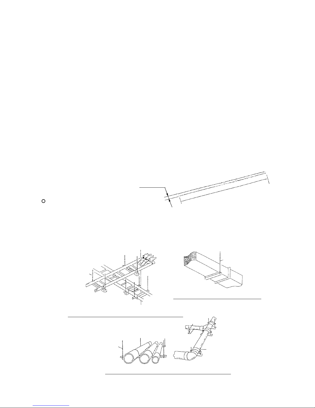
One of the primary uses of studs is for hanging of electric cable racks, air-conditioning ducts, and plumbing pipes
and drains. Studs are usually sold in standard lengths of 1 to 3 meters, and must be cut to desired lengths in
accordance with installation needs. They are currently being cut by cut-off machines, disc grinders, or manual
hack saws, frequently require the use of files and grinders for deburring and finishing before they can be used.
The Model CL 10D2 is the upgraded version of the Model CL 10D and is easier to operate and less expensive
with the same features such as clean cutting without sparks, dust and noise, minimal damage to studs and easy
processing after cutting. Thanks to the weight reduction of the motor, decelerating and cutting mechanisms, the
Model CL 10D2 weighs only 3.2 kg even though it uses the 12 V battery while the Model CL 10D using the 9.6 V
battery weighs 3.4 kg. The Model CL 10D2 becomes low price thanks to renewing the manufacturing processes
and sharing components with other models. In addition, the Model CL 10D2 is capable of cutting up to 550 studs
per single charge (when cutting M10 soft steel studs using the 12 V NiMH battery with nominal capacity 3.0 Ah).
This is about 4 times the capacity of the Model CL 10D. The Model CL 10D2 can correspond to various
applications with the wide selection of cutters (M10, M8, M6 and W3/8) and
can be used anywhere since it is cordless.
3. APPLICA TIONS
Cutting of mild-steel studs
[Typical threaded stud applications]
Electric installation
•••••••••••••••••••
Suspension of luminaiers, cable racks, conduit pipes, etc.
Air-conditioning
•••••••••••••••••••••••
Suspension of air-conditioning ducts, exhaust ducts, etc.
Plumbing installation
••••••••••••••••
Suspension of feed and drain pipes
Fig. 1
1 to 3 m
M6 to M10
Fig. 2
(2) Suspension of air-conditioning ducts
(3) Suspension of feed and drain pipes in plumbing work
(1) Suspension of cable racks in electrical installation
Stud
Stud
Stud
Stud
Page 5
--- 2 ---
4-1. Selling Point Descriptions
(1) Clean cutting without sparks, chips and noise
A safer and better working environment without fear of fire or scattering of chips and dust is ensured because the
Model CL 10D2 does not produce the chips, dust, and sparks unlike cut-off machines and disc grinders.
4. SELLING POINTS
Fig. 5 Clean shearing with Model CL 10D2
Fig. 3
Fig. 4 Cutting by cut-off machine
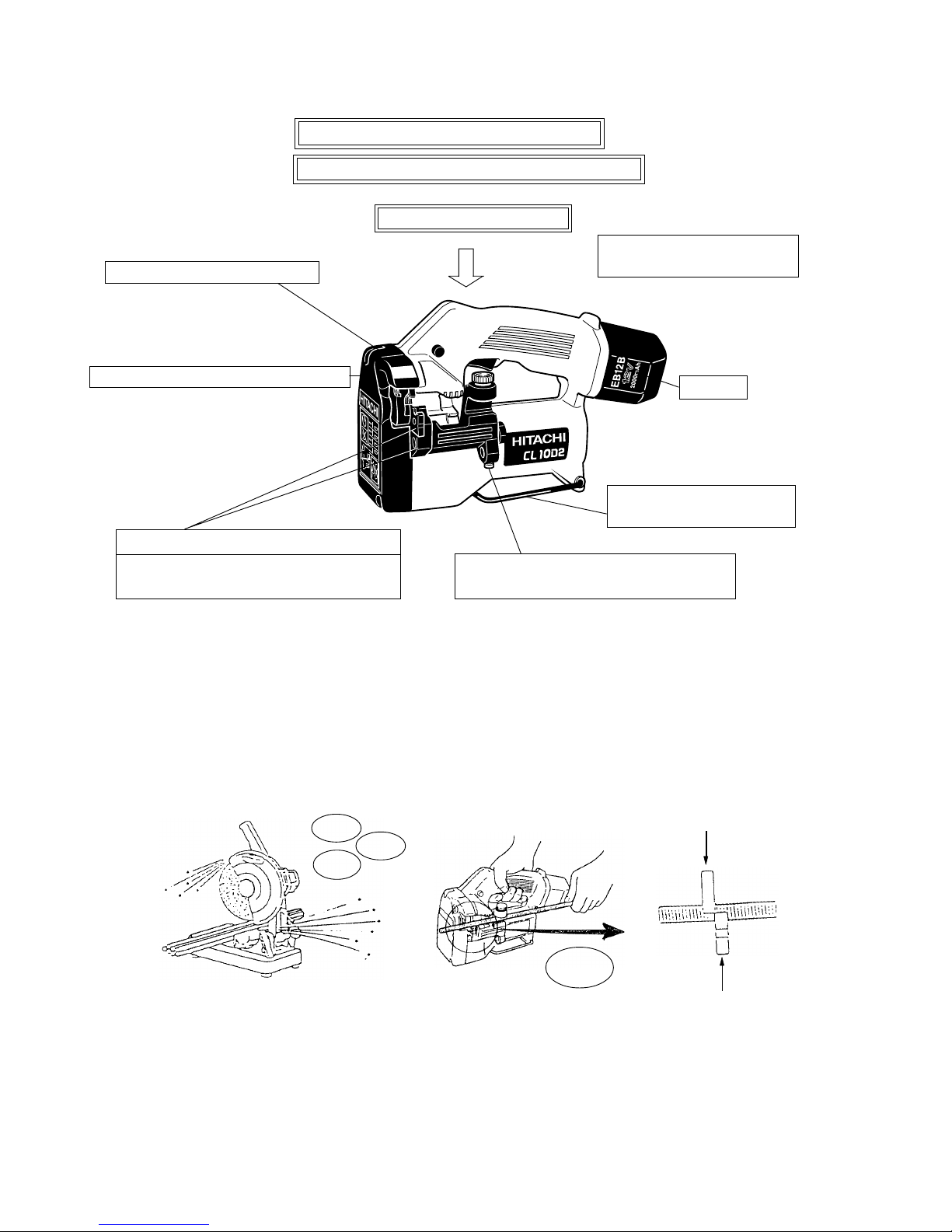
Excellent working efficiency
Clean cutting without sparks, chips and noise
24 mm minumum cutting length
Special steel made long service life cutter
Service life of cutters increased through
use of four cutting edges
Convenient stud mounting hole facilitates
cutting studs to specified lengths
Convenient hook facilitates
operation in high places
Cordless
Cam-operated auto-return mechanism
Lightweight 3.2 kg (7.05 lbs.)
(CL 10D: 3.4 kg (7.5 lbs.))
Shearing force: 2500 kg
Clean
cutting
Sparks
Chips
Noise
Minimal damage to studs permits easy processing
Page 6
--- 3 ---
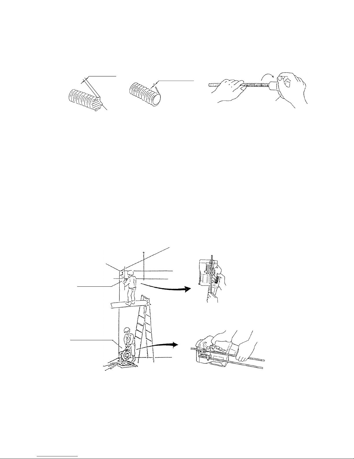
(2) Minimal damage to studs permits easy processing
Because of the special cutters employed, few burrs are caused during cutting, and nuts can be attached to the
studs smoothly and easily. Deburring can be done easily and quickly by means of the provided trimmer.
(3) Cordless
The length of a stud is basically determined by the various needs of the work site. If the ceiling is slanted, for
example, it is hard to determine appropriate lengths. In such a case, it is common to hang studs which are longer
than the required length, and mark and cut them off later. When mounting ducts, up to 20 studs can be cut at a
time at floor level (with a cut-off machine, for example). When mounting luminaiers, however, often only two studs
are cut in one spot. This means that the cut-off machine must be moved from one spot to another over a wide
area.
The Model CL 10D2 is compact, lightweight, and cordless, so it is easily transportable and particularly convenient
for cutting off hanged studs. In addition, it is capable of cutting up to 550 studs per single charge, so it has
sufficient operability to cut many studs at floor level as well.
(1) 20 to 30 % of studs are cut after being hanged.
Fig. 8 Illustration of stud cutting work
Fig. 6 Comparison of stud condition after cutting
Fig. 7 Deburring of stud with trimmer
2 to 3 mm
0.2 to 0.3 mm
Necessary torque: 5 kg-cm or below
Trimmer
Disc grinder
Cut-off machine
(2) 70 to 80 % of studs are cut at floor level.
[Stud cut with cut-off machine]
[Stud cut with Model CL 10D2]
Burr
Page 7
--- 4 ---
Cutter (1)
4th
3rd2nd
1st
(4) Long service life through use of stud cutting edges
Because of the uniquely shaped cutters specially developed by HITACHI, each cutter has four (front, back, upper,
and lower) which can be used in turn for cutting studs. Each cutter is made of high wear-resistant, special steel,
and is capable of cutting up to 500 studs with each of its cutting edges. Accordingly, up to 2,000 studs can be cut
with appropriate use of the four cutting edges.
(5) Excellent working efficiency
In conventional cutting with a cut-off machine or disc grinder, considerable time is required for deburring after the
studs have been cut. In actual tests, the Model CL 10D2 is approximately three times more efficient than cut-off
machines or disc grinders.
Table 1. Cutting time comparison
Table 2. Number of studs that can be cut per battery charge
Fig. 9
Four cutting edges
Reverse cutters
by turning each,
top to bottom.
Cutter (2)
Reverse cutters
by turning each,
side to side.
Reverse cutter (1)
and cutter (2)
mounting positions.
Reverse cutters
by turning each,
top to bottom.
Type of cutting tool
Cordless stud cutter CL 10D2
Cordless stud cutter CL 10D
High-speed cut-off machine
Grinder
Hand saw
Cutting time
10
(sec.)
2.6 (M10)
2.4 (M10)
30 to 60
8
20
30
Stud size
M6
M8
W 3/8"
M10
Number of cuts per charge
EB 1230H
EB 12B
(Piece)
1270
850
850
570
550
370
620
410
Page 8
--- 5 ---
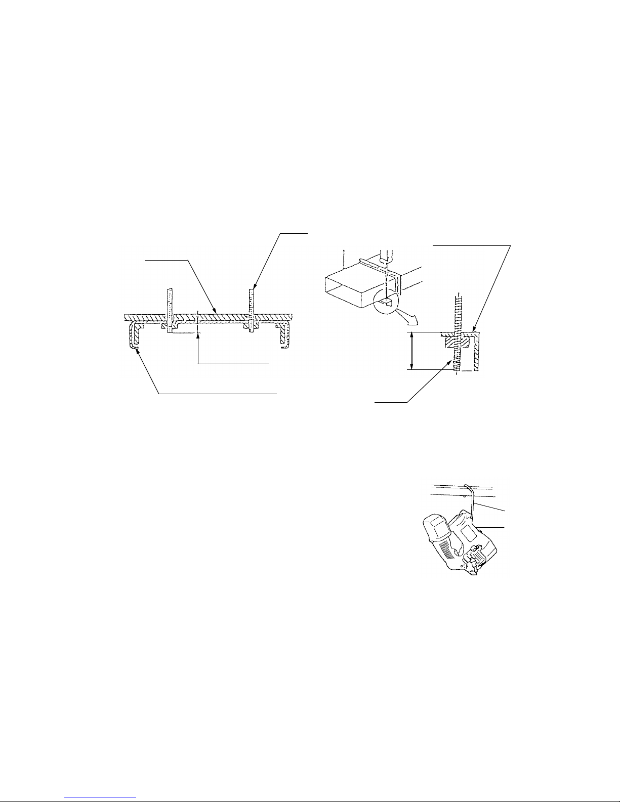
(6) Minimum cutting length
As illustrated in Fig. 10, it is sometimes necessary to cut studs 30 mm or less from the ceiling surface when
installing fluorescent lamps in electrical installation work. The Model CL 10D2 permits cutting protruding studs to
a minimum length of 24 mm from the ceiling surface.
In addition, when installing ducts in air-conditioning equipment installation work, it may be necessary to enclose
the ducts with insulation (lagging) after installation to prevent the formation of dew. In such a case, studs must be
cut as short as possible so that they do not protrude from L-shaped angles, in order to prevent damage of the
lagging. As illustrated, the Model CL 10D2 permits cutting of studs within an L-shaped angle measuring 25 mm x
25 mm x 3 mm (t).
Fig. 10 Minimum cutting length
(7) Convenient hook facilitates operation in high places
When performing equipment installation work in high places, cutting of
hanging studs is often only one of several jobs that must be performed.
Accordingly, it is sometimes necessary to put the stud cutter aside and use
both hands for some other job. In such cases, the hook is very useful for
hanging the stud cutter from a nearby conduit, steel grounding material,
cable rack, or similar support when not in use.
30 mm or less
Fluorescent lamp fixture
L-shaped angle
25
Ceiling
Stud
Stud
Fig. 11 Convenient hook facilitates
operation in high places
Hook
Latch
Page 9

--- 6 ---
(8) Convenient stud mounting hole facilitates cutting studs to specified lengths
The stud mounting hole is very convenient when cutting many studs to the same length at floor level. The
adjustable stud mounting hole permits mounting of M6 to M10 studs, and can be used as an accurate cutting
length guide for the full range of applicable studs. It can be used not only to align cutting lengths to the rear of the
main body, as shown in Fig. 12-(1), but also to align cutting lengths to the front of the main body, as shown in
Fig. 12-(2). The stud mounting hole is particularly convenient when it is necessary to cut several studs at the
same length from, for example, the surface of a ceiling.
Fig. 12-(1) Length alignment to rear of
main body
Fig. 12-(2) Length alignment to front
of main body
Fig. 12 Stud mounting hole facilitates cutting to specified lengths
(9) Cam-operated auto-return mechanism
After cutting, the cutter is forcibly returned (opened) by means of a plate cam commonly called a "return plate".
This mechanism prevents such malfunctions as the cutter becoming jammed and not returning.
Stud mounting hole
Specified-length guide stud
Specified-length
guide stud
Page 10

--- 7 ---
Battery (Type EB 12B)
Capacity
Number of cuttings per battery charge (M10)
Cutting time
Type of motor
Enclosure
Type of switch
No-load stroke
Main body
Battery
5. SPECIFICATIONS
5-1. Specifications
Mild steel studs: M10, M8, M6 or W3/8"
550 cuts powered by Battery EB 1230H
2.3 (sec.)
DC magnet motor
Main body : Glass fiber reinforced polyamide resin
Battery: ABS resin
Charger: ABS resin
Trigger switch with forward/reverse changeover (with brake)
30/min.
3.2 kg (7.05 lbs.) (includes battery)
EB 1230H: 0.66 kg (14.6 lbs.), EB 12B: 0.67 kg (14.8 lbs.)
Corrugated cardboard box < W/Plastic case: 6.2 kg (13.7 lbs.)>
Standard accessories
W/Charger
Plastic case............................................................................ 1 pc.
Battery (EB 1230H or EB 12B) .............................................. 1 pc.
Charger (UC 14YF2).............................................................. 1 pc.
Hex. bar wrench..................................................................... 1 pc.
M8 cutter ass'y ....................................................................... 1 pc.
M8 trimmer ............................................................................. 1 pc.
Sealed cylindrical nickel-cadmium batteries
Nominal voltage: DC 12V
Nominal life: Charging/discharging approximately 1,000 cycles
(in case of Model UC 14YF2)
Nominal capacity: 2.0 Ah
Sealed cylindrical nickel-metal hydride batteries
Nominal voltage: DC 12V
Nominal life: Charging/discharging approximately 500 cycles
(in case of Model UC 14YF2)
Nominal capacity: 3.0 Ah
Battery (Type EB 1230H)
Sealed power source: Single-phase AC 50/60 Hz
Voltage: Depending on the order specification
Power input: 44 W
Charging system: Constant current charge with full wave phase control
Overcharge protection system: (1) Battery voltage detection (
2
V system)
(2) Battery surface temperature detection
(thermostat or thermistor)
(3) 120-minute timer
Output voltage: 7.2 V --- 14.4 V
Output current: 1.9 A
Charging time: Approx. 60 minutes (for B-type storage battery at 20˚C (68˚F))
Approx. 90 minutes (for H-type storage battery at 20˚C (68˚F))
Product weight: 1.3 kg
Operable ambient temperature range: 0˚C --- 40˚C (32˚F --- 104˚F)
The maximum allowable temperature of the EB 12B type battery is 60˚C
(140˚F) and the EB 1230H type battery is 45˚C (113˚F).
Charger (Type UC 14YF2)
Weight
Packaging and
packaged weight
Page 11
--- 8 ---
Read pilot lamp
remains lit or flashes.
Green pilot lamp is lit.
Prior to charging
During charging
Charging completed
Charging not possible
High battery
temperature
Blinks
Lit
Blinks
Flickers
Lit
0.5 sec ON, 0.5 sec OFF
0.5 sec ON, 0.5 sec OFF
Stays ON constantly
Stays ON constantly
0.1 sec ON, 0.1 sec OFF
Storage battery or
charger is faulty.
Charging not possible
because storage battery
temperature is too high.
Pilot lamp indications (UC 14YF2)
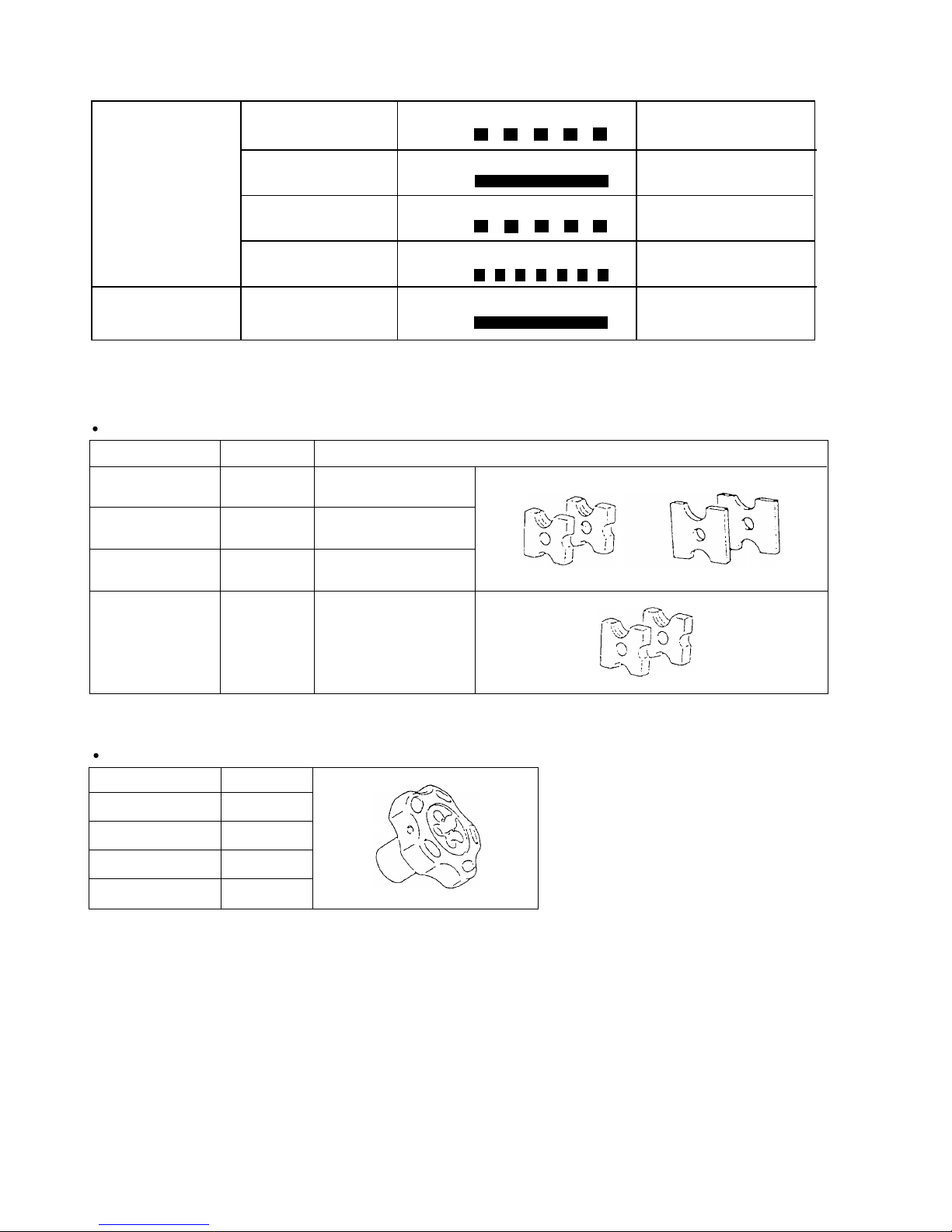
5-2. Optional Accessories
Cutter ass'y
Stud size
Code No.
Combining cutters and spacers
M10 x 1.5
M10 Cutter 2
M10 Spacer 2
308565
*
W3/8" x 1.5875
M6 x 1
M8 x 1.25
308563
308564
M8 Cutter 2
M8 Spacer 2
M6 Cutter 2
M6 Spacer 2
W3/8" Cutter 2
998479
+
Trimmer
Stud size
Code No.
M10 x 1.5
308570
* W3/8" x 1.5875
M6 x 1
M8 x 1.25
308568
308569
308567
* The W3/8" is used without spacers.
Page 12

--- 9 ---
Hitachi
M10 x 1.5
M8 x 1.25
M6 x 1
W3/8" x 1.5875
DC 12
30
61
281 mm (11-1/16")
179 mm (7-3/64")
107 mm (4-7/32")
Voltage
Power input
No-load stroke
No-load sound pressure level
Dimensions
V
W
min
-1
dB (A)
6. COMPARISONS WITH SIMILAR PRODUCTS
6-1. Specification Comparisons
Maker, model
Catalog specifications
CL 10D2
M10 x 1.5
M8 x 1.25
M6 x 1
W3/8" x 1.5875
AC 230 or more
190
0 to 32
73
235 mm (9-1/4")
182 mm (7-11/64")
107 mm (4-7/32")
M10 x 1.5
M8 x 1.25
M6 x 1
W3/8" x 1.5875
DC 9.6
0 to 28
66
258 mm (10-5/32")
179 mm (7-3/64")
107 mm (4-7/32")
Capacity:
Soft steel studs (Size of studs for cutting)
CL 10D
CL 10SA
Length
Height
Width
Weight
3.2 kg (7.05 lbs.)
(including battery)
3.4 kg (7.5 lbs.)
(including battery)
2.7 kg (5.95 lbs.)
(excluding cord)
2.4
550
2.6
140
2.4
NA
Cutting time (M10)
Number of cuttings per battery charge
(M10)
Type of motor
DC magnet
AC single-phase
series commutator
motor
DC magnet
Trigger switch with
forward/reverse
changeover pushing
button with brake
Trigger switch with
forward/reverse
changeover pushing
button with brake and
variable
Trigger switch with
forward/reverse
changeover pushing
button with brake and
variable
Type of switch
Battery Type
Nominal capacity Ah
Nominal voltage V
Charger Model
EB 1230H or EB 12B
EB 1230H: 3.0
EB 12B: 2.0
12
UC 14YF2
Standard accessories
EB 9B
9.6
UC 12Y
Plastic tool case
Charger (UC 14YF2)
Hexagon bar wrench
M8 cutter ass'y
M8 trimmer
Plastic tool case
Charger (UC 12Y)
Hexagon bar wrench
M8 cutter ass'y
M8 trimmer
Hexagon bar wrench
M8 cutter ass'y
M8 trimmer
Item
sec.
2.0
Page 13

--- 10 ---
7. PRECAUTIONS IN SALES PROMOTION
7-1. Safety Instructions
In the interest of promoting the safest and most efficient use of these tools by all of our customers, it is very
important that at the time of sale the salesperson carefully ensures that the buyer seriously recognizes the
importance of the contents of the Handling Instructions, and fully understands the meaning of the precautions
listed on the Caution Plate and Name Plate attached to each tool.
A. Handling Instructions
Salespersons must be thoroughly familiar with the contents of the Handling Instructions in order to give pertinent
advice to the customer. In particular, they must have a thorough understanding of the precautions in the use of
the cordless (battery charger type) electric power tool which are different from those of ordinary electric power
tools.
(1) Before use, ensure that the unit is fully charged.
New units are not fully charged. Even if the units were fully charged at the factory, long periods out of use,
such as during shipping, cause the storage battery to lose its charge. Customers must be instructed to fully
charge the unit prior to use.
(2) When charging storage batteries, use only the exclusive Model UC 14YF2 Charger provided with the tool.
Because of the designed rapid-charging feature (about one hour), use of other battery chargers is hazardous.
(3) Follow prescribed steps in using the Charger.
First connect the EB 1230H or EB 12B Storage Battery to the Model UC 14YF2 Charger, then plug the
Charger into an AC outlet (ensuring that the voltage matches that indicated on the unit). If this order is
reserved, the charger may not function properly.
(4) Ensure the power source voltage is the same as that indicated on the name plate of the Charger. Use of any
other power source (DC outlet, fuel powered generator, etc.) will cause the Charger to overheat and burn out.
(5) Do not use any voltage increasing equipment (transformer, etc.) between the power source and the Charger.
If the Charger is used with voltage over and above that indicated on the unit, it will not function properly.
(6) Conduct battery charging at an ambient temperature range of 0˚C to 40˚C (32˚F to 104˚F).
Special temperature sensitive devices are employed in the Charger to permit rapid charging. Ensure that
customers are instructed to use the Charger at the indicated ambient temperature range. At temperature
under 0˚C (32˚F), the thermostat will not function properly, and the storage battery may be over-charged.
At temperature over 40˚C (104˚F), the storage battery cannot be sufficiently charged.
The optimum temperatures range is 20˚C to 25˚C (68˚F to 77˚F).
(7) The battery charger should not be used continuously.
At high ambient temperatures, if over three storage batteries are charged in succession, the temperature of
the coils on the transformer will rise and there is a chance that the temperature fuse inserted in the interior of
the transformer will inadvertently melt. After charging one battery, please charge the next battery after about a
fifteen-minute interval.
(8) The Charger case is equipped with air vents to protect the internal electronic components from overheating.
Caution the customer not to allow foreign materials, such as metallic or flammable objects, to be dropped or
inserted into the air vents. This could cause electrical shock, fire or other serious hazards.
Page 14

--- 11 ---
(9) Do not attempt to disassemble the storage battery or the charger.
Special devices, such as a thermostat, are built into the storage battery and charger to permit rapid charging.
Incorrect parts replacement and/or wiring will cause malfunctions which could result in fire or other hazards.
Instruct the customer to bring these units to an authorized service center in the event repair or replacement is
necessary.
(10) Disposal of the Model EB 1230H or EB 12B Storage Battery
Ensure that all customers understand that Model EB 1230H or EB 12B Storage Batteries should be turned
into any Hitachi Power Tool sales outlet or authorized service center when they are no longer capable of
being recharged or repaired. If thrown into a fire, the batteries may explode, or, if discarded indiscriminately,
leakage of the cadmium compound contained in the battery may cause environmental pollution.
(11) Perform cutting only after confirming that the threads of the stud cutter properly engage the threads of the
stud. If the threads are not properly engaged, damage to the threads of the stud during cutting may make the
stud unusable, and/or the cutter blade may be damaged.
(12) Ensure that the portion cut off of the stud is at
least 10 mm in length.
As the blade portion of the cutter is very thin,
if only one or two threads of the cutter are
engaged with the threads of the stud, as
illustrated in Fig. 13, the excessive
concentration of load on the blade portion will
cause it to break after only a few cutting
operations. The length of stud cut off should
be at least 10 mm. Instruct customers to
confirm that all of the threads of the cutter
engage the threads of the stud during cutting.
(13) Care should be exercised when performing cutting in narrow places.
For example, in building construction work, studs that are used to hang ducts are often fitted with L-shaped
angles. Instruct the customers to ensure that there is a clearance of at least 8 mm between the stud and the
angle when 25 mm or 30 mm L-shaped angles are used, as illustrated in Fig. 14, before starting the cutting
operation. If the clearance is less than 8 mm, Bracket (A) will come in contact with the side surface of the
angle, preventing proper engagement of the threads of the cutters and the threads of the stud, and causing
damage to the threads of the stud and/or the cutter blade.
Also, since the minimum cutting length of a stud is 14 mm from the surface of the nut, the stud can be cut off
at a point 5 mm within the tip of the angle in the case of a 30 mm L-shaped angle, and approximately even
with the tip of the angle in the case of a 25 mm L-shaped angle, as illustrated in Fig. 14. If cutting is
attempted shorter than indicated, Bracket (A) will come in contact with the nut, causing possible damage to
the cutter. Accordingly, particular caution is necessary.
Fig. 13
Cutter
Cutter
Damaged blade
10 mm or more
Page 15

--- 12 ---
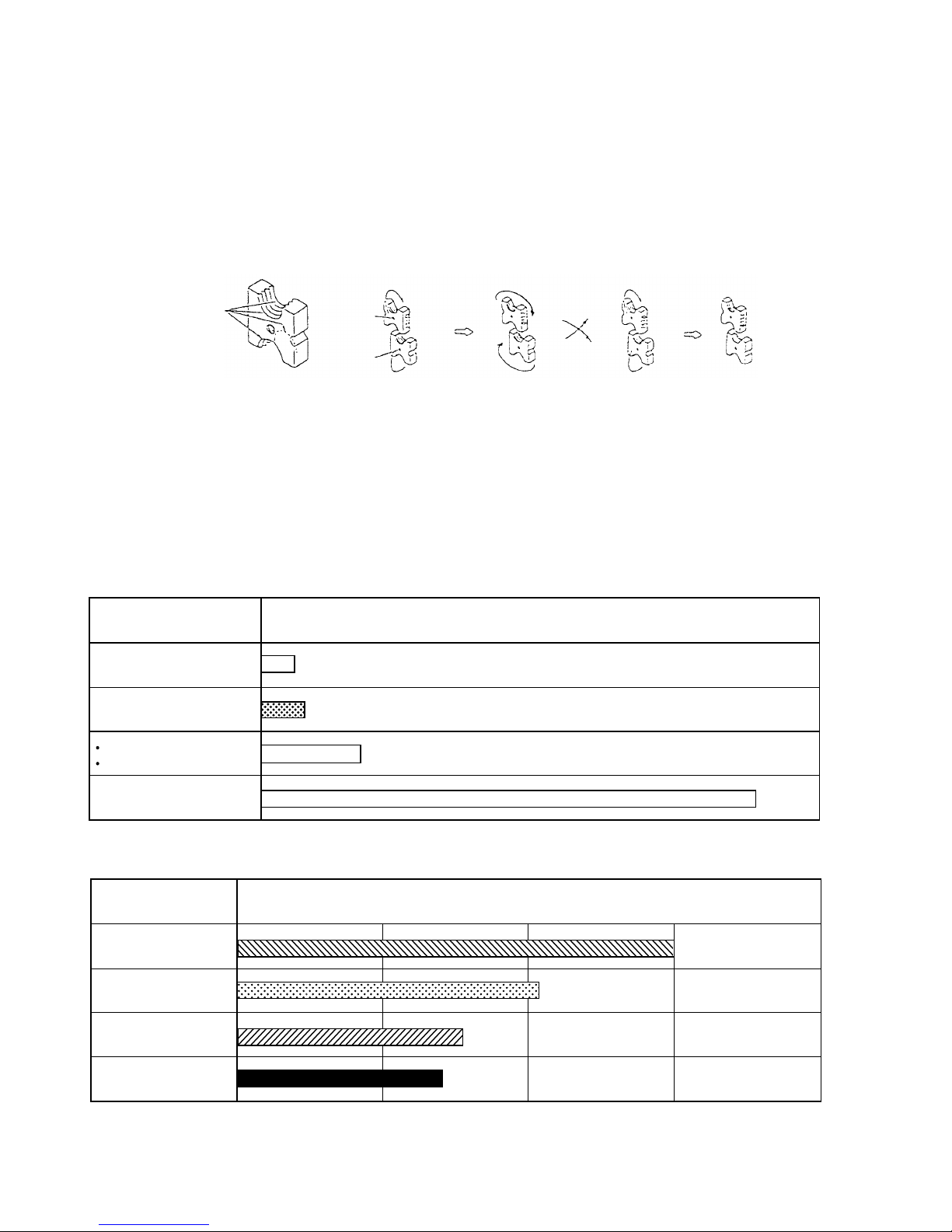
(14) Precautions in cutter replacement
The cutters must be mounted in the proper directions. Instruct the customers to ensure that the notched
grooves on the side surfaces of the cutters are in a "Yes" and "No" relationship when viewed from the front
end of the main body, as illustrated in Fig. 15. In other words, when the notched groove is present (Yes) on
one cutter, it must not be present (No) on the other. If the two cutters are in "Yes" and Yes" alignment, or
"No" and "No" alignment, the pitch of the threads of the stud will not match the pitch of the threads of the
cutters, as illustrated in Fig.16. In such a case, the cutter blade will be damaged and/or the main body of the
stud cutter will become defective after a short period of operation.
(15) Never attempt cutting operation at the position.
If the storage battery charge runs out and motor rotation stops during
cutting, pull the switch (in the position) while pressing the
forward/reverse changeover button from the left, as shown in Fig. 17,
to disengage the cutter from the stud. As the motor is locked
at the position, cutting of a stud cannot be performed, even
if the storage battery is fully charged. In addition, as excessive
pressure or twisting force applied to the main body can seriously
damage the tool, the customers should be instructed never to
attempt to forcibly free the cutters from the stud.
Fig. 17
Fig. 14
Fig. 16
Fig. 15 Cutter replacement method
Notched groove
"Yes"
"Yes"
"No"
"No"
Stud
(30 mm L-shaped angle)
(24 mm L-shaped angle)
L-shaped angle
8 mm or more
Nut
25
14
30
5
0
Page 16

--- 13 ---
(16) The amount of work possible per battery charge varies. The nominal capacity of the storage battery in the
main body is 3.0 or 2.0 Ah. However, the actual capacity varies plus or minus approximately 10% depending
on the ambient temperature during charging/discharging and the number of times the battery has been
recharged. As the amount of work per charge also varies depending on the working conditions (ambient
temperature, sharpness of the cutters, etc.), the data contained herein is intended for reference value only.
(17) The Model CL 10D2 is designed for cutting mild steel studs. If the tool is used for cutting brass or stainless
steel studs, the threads of the studs will be deformed so that nuts cannot be applied. In addition, as use of
the tool to cut hardened bolts, different-sized studs, reinforcing rods, etc. will cause damage to the main
body, the customers should be cautioned never attempt to use the tool for such purposes.
(18) Carefully ensure that replacement cutters are appropriate for the stud sizes. As use of wrong-sized cutters
will cause damage to the studs and/or cutter blades, the customers should be cautioned to ensure that
correct cutters are used.
(19) If the cutters are not mounted in the proper direction, or if the fastening hexagon socket head bolts are not
properly tightened, it will cause damage to the cutters and the main body of the tool. Instruct the customer to
ensure that the cutters are properly mounted.
(20) When operating the tool in high places, the falling cut-off stud portions are extremely dangerous.
The customers should be cautioned to be particularly careful at such times. In addition, the tool should be
stored in a safe, secure place when not in use.
(21) When the tool is being carried, when it is stored away, or when it is temporarily not in use, instruct the
customer to set the forward/reverse changeover button to the position so that the switch cannot be
turned on inadvertently.
(22) When operating the switch, carefully ensure that fingers are kept away from the cutters. To enhance safe
operation, the Model CL 10D2 is provided with a cover for the moving portion of the cutters, a housing
shaped so that fingers are kept away from the cutters, a switch without a stopper, and other safety features.
However, the opening to the cutters must be exposed to permit operation. Should the switch be turned on
inadvertently when the fingers are carelessly near the cutters during replacement or cleaning of the cutters,
while carrying the tool, or at any other time, serious injury could result. The customers should be cautioned
to keep fingers away from the cutters whenever the storage battery is installed in the tool.
B. Caution Plate
(1) The following cautions are listed on the caution plate attached to each Model EB 1230H or EB 12B Storage
Battery.
For Europe
Page 17

--- 14 ---
7-2. Suggestions and Precautions for Efficient Use of Charger
Batteries may not be chargeable immediately after use:
If the type EB 1230H or EB 12B storage batteries are exposed to direct sunshine for an extended period, of if the
temperature of the batteries is 40˚C (104˚F) or higher immediately after they have been used in the tool, the pilot
lamp may not light up when the batteries are connected to the Model UC 14YF2 Charger. This is because the
built-in-thermostat functions to stop the charging when the temperature of the storage batteries reaches 40˚C
(104˚F) or more. In such a case, the customer should be advised to place the batteries in a shaded area with a
good airflow, and allow sufficient cooling before recharging.
This phenomenon is common to all existing batteries which employ temperature sensitive over-charge devices.
The cooling time required before charging can be accomplished varies from a few minutes to about 30 minutes,
depending on the load, duration of use, and ambient temperature.
Page 18

--- 15 ---
Fig. 18
8. REPAIR GUIDE
WARNING: Without fail, remove the storage battery from the main body of the tool before starting repair
or maintenance work. If the battery is left in and the switch is activated inadvertently, the
motor will start rotating unexpectedly, which could cause serious injury.
8-1. Precautions in Disassembly and Reassembly
The [Bold] numbers in the description below correspond to the item numbers in the Parts List and exploded
assembly diagram for the Model CL 10D2.
8-1-1. Preparation to disassembly (Fig. 18)
Before disassembly, set the Pushing Button [3] to the position and depress the trigger switch until Bracket
(A) [42] opens. Then release the trigger switch and remove the storage battery.
Remove the two Special Bolts M5 x 9 [50] from the two Cutter Ass'y M8 [52] with the Hex. Bar Wrench 4 mm [11]
(standard accessory). Insert the storage battery in the main body. Depress the trigger switch keeping the
Pushing Button set to the position until Bracket (A) [42] is positioned to the maximum cutting position. Then
release the trigger switch and remove the storage battery.
Fig. 19
On completion of the above preparation, be sure to
disconnect and remove the battery. Remove the
Bolt W3/8 x 75 [48], loosen the Spring Washer M10
[47], and take off the Stud Guide Ass'y [46]. (Fig. 19)
(a) (b)
Maximum
cutting
position
position
[38]
[37]
[50]
[52]
[42]
[3]
[46]
[47]
[48]
Page 19

--- 16 ---
8-1-2. Disassembly
(1) Bracket ass'y section
(a) Removal of the Cover [38] (Fig. 18)
Remove the two Machine Screws (W/Washers) M4 x 20 (Black) [37] from the Cover [38] and remove the
Cover [38].
(b) Removal of the Return Plate [41] (Fig. 20)
Remove the two Seal Lock Screws (W/SP. Washer) M4 x 12 [40] and remove the Return Plate [41].
(c) Removal of the Gear Cover [19] (Fig. 20)
Remove the four Tapping Screws (W/Flange) D5 x 25 (Black) [17] and the two Tapping Screws D5 x 35 [43].
Hold Bracket (B) [44] and Bracket (A) [42] and remove them being careful not to move Bracket (A) [42].
Then the Second Gear [22] and the Third Pinion [21] can be removed (Fig. 21).
Fig. 20
Fig. 21
Press-fitted
[43]
[17]
[41]
[40]
[44]
[19]
[42]
[21]
[22]
Page 20

--- 17 ---
Fig. 24
Fig. 22 Fig. 23
(d) Removal of the Final Gear [35] (Fig. 22)
Remove the Retaining Ring for D18 Shaft [36] that retains the Final Gear [35] and the Cam Shaft [55] with
the stop ring pliers. Remove the Final Gear [35] and the two Feather Keys 5 x 5 x 10 [56]. Then the Cam
Shaft [55] can be removed.
(e) Removal of the bracket ass'y (Figs. 23 and 24)
Remove the three Hex. Socket Hd. Bolts M5 x 12 [34] from Bracket (B) [44] with the Hex. Bar Wrench 4 mm
[11]. Holding Bracket (A) [42] and Bracket (B) [44], remove the bracket ass'y being careful not to make the
Return Spring [18] jump up.
[34]
[56]
[55]
[36]
[35]
[18]
[42]
[44]
Page 21

--- 18 ---
Fig. 26
(f) Disassembly of the bracket ass'y
(i) Removal of Bolt (A) [39] (Fig. 25)
Bolt (A) [39] that secures Bracket (A) [42] to Bracket (B) [44] is press-fitted into Bracket (B) [44] and
tightened with the Lock Nut M12 [45]. Hold Bracket (B) [44] with a vise and loosen the Lock Nut M12 [45]
with a wrench (loosening torque: about 350 kg•cm). Supporting around the head of Bolt (A) [39] of
Bracket (A) [42], push the screw side of Bolt (A) [39] with a hand press to separate Bracket (A) [42] from
Bracket (B) [44].
(ii) Removal of Roller (A) [53] (Fig. 26)
The Roller Pin [54] that secures Roller (A) [53] is press-fitted into Bracket (A) [42]. Remove the Roller Pin
[54] by pushing in either direction with a hand press. Then Roller (A) [53] can be removed.
Push with a
large hand
press.
Hold at these positions with a vise and
loosen the Lock Nut M12 [45].
Support
here.
Fig. 25
[39]
[42]
[45]
[44]
[44]
[39]
[42]
[42]
[54]
[53]
Page 22

--- 19 ---
(2) Housing ass'y section
(a) Removal of the Hook [6] (Fig. 27)
Remove the Retaining Ring (E-Type) for D4 Shaft [10] that retains the Hook [6] with a small flat-blade
screwdriver. Then the Hook [6] can be removed.
(b) Removal of Housing (B) [2]
Remove the nine Tapping Screws (W/Flange) D4 x 20 (Black) [8] that secure Housing (A) [2] to Housing (B)
[2]. Holding the compartment of the Gear Cover [19] in Housing (A) [2] and Housing (B) [2] or the
compartment of the battery, remove Housing (B) [2] carefully.
Fig. 27
Housing (A) [2]
Housing (B) [2]
[10]
[8]
[6]
Page 23

--- 20 ---
(c) After removal of Housing (B) [2], the internal assemblies and parts can be removed (Fig. 28).
First, remove the Switch Holder [12]. Holding the Pushing Button [3] and the Spring [4], remove the Switch
[13]. Remove the Terminal Support [15]. Remove the Motor [33] and the Second Pinion [28] from Housing
(A) [2].
Fig. 28
[15]
[3]
[4]
[14]
[12]
[13]
[28]
[33]
(3) Power supply unit section
Remove the internal wires coming from the Motor [33] and the Switch Ass'y [14] from the Switch [13] with a
soldering iron.
CAUTION: Do not apply heat to the Switch [13] for a long time with the soldering iron when removing the
internal wires. Otherwise, the electronic circuit in the Switch [13] can be damaged.
Page 24

--- 21 ---
(4) Second pinion section (Fig. 29)
Remove the Ball Bearing 6001VVCMPS2L [32] press-fitted into the Second Pinion [28] with a bearing puller.
Then the Washer [31] can be removed. Remove the Ball Bearing 609VVC2PS2L [24] in the same manner
and remove the Retaining Ring for D15 Shaft [25] with the stop ring pliers. Then the Washer [26] can be
removed. Remove the Needle [30] and the Idle Gear [29].
8-2. Reassembly
Reassembly can be accomplished by following the disassembly procedures in reverse. However, particular
attention should be given to the following items.
(1) Reassembly of the power supply unit section
Be sure to perform wiring connections as indicated in the wiring diagram below (Fig. 30).
Fig. 30
Fig. 31
Red
Blue
Brown
Brown
Blue
Black
Red
Black
[33]
[15]
[13]
[13]
"+" side
"---" side
Red mark
The "+" side is indicated with a red mark on the Motor [33] (Fig. 31).
[24]
[25]
[26]
[28]
[29] [30]
[32]
[31]
Fig. 29
[14]
Page 25

--- 22 ---
(2) Reassembly of the housing section
(a) Second Pinion [28] (Fig. 32)
Before inserting the Needle [30] in the Second Pinion [28], apply grease (Nippeco SEP-3A) to the inner
circumference of the two Idle Gears [29]. Mount the Washer [31] facing its smaller diameter side to the Ball
Bearing 6001VVCMPS2L [32]. Mount the Washer [26] and then the Retaining Ring for D15 Shaft [25] using
the stop ring pliers. Press-fit the Ball Bearing 6001VVCMPS2L [32] and the Ball Bearing 609VVC2PS2L [24].
Check that the Ring Gear [27]
and the Second Pinion [28] are
rattling in a direction at the right
angle to the straight line
connecting the two Needles [30].
(b) Planet gear (Fig. 33)
First, apply grease (Nippeco SEP-3A) to the inner circumference of the Ring Gear [27]. Mount the pinion of
the Motor [33] to the Second Pinion [28] assembled according to the above step (a) and mount the Ring Gear
[27]. Check that the Ring Gear [27] and the Second Pinion [28] are rattling. If there is no rattle (gears are not
engaged properly), the Motor [33] will be locked. Mount this assembly to Housing (A) [2] mating the
protrusion of the Ring Gear [27] to the groove of Housing (A) [2].
Smaller diameter side
Fig. 32
[24]
[31]
[25]
[26] [28]
[29]
[30]
[32]
[12]
[13]
[3]
[4]
Housing (A) [2]
[33]
[7]
[27]
Upper: Blue "---"
Lower: Brown "+"
[27]
[28]
[30]
Fig. 33
Protrusions
(Upper and lower)
Page 26

--- 23 ---
(3) Reassembly of the bracket ass'y section
(a) Lubrication (Fig. 36)
Sufficiently apply grease to Bracket (A) [42], Bracket (B) [44], Roller (A) [53],
Cam Shaft [55], coupling portion and rotating portion of Bolt (A) [39] because high loads are applied to these
parts. Also apply grease to the inner circumferences of the punched holes of the Return Plate [41] and the
sliding portions of the Return Spring [18] and Bracket (A) [42]. Apply TUFREX 251 grease to the shafts, holes
and surfaces indicated with diagonal lines and two-dot chain lines in Fig. 36. Carefully apply grease to the
inner circumference of the hole of Roller (A) [53] until the grooves in the hole are completely greased.
(b) Mounting Roller (A) [53]
Check the position of the smaller diameter end of the Roller Pin [54] and insert the Roller Pin [54] in the hole
of Bracket (A) [42] in the proper direction as shown in Fig. 36. Align Roller (A) [53] with the hole of Bracket (A)
[42] and press-fit the Roller Pin [54] until it becomes flush with the end surface of Bracket (A) [42] (Fig. 36).
(c) Power supply unit (Fig. 33)
Mount the power supply unit assembled according to the above step (1) to Housing (A) [2]. Connect the
internal wires of the Switch Ass'y [14] locating the blue internal wire at the upper position and the brown
internal wire at the lower position. (Housing (A) [2] and Housing (B) [2] are indicated with "+" and "---"
respectively. Be sure to connect the brown internal wire to the "+" side and the blue internal wire to the "---"
side. Otherwise the Switch [13] can be broken.) Then mount the Switch Holder [12] being careful of the
direction.
(d) Mount the Pushing Button [3] mating its groove to the lever of
the Switch [13] (Fig. 34).
(e) Mount the Spring [4] to the Pushing Button [3] (Fig. 33).
(f) Mount the Wrench Holder [7] to Housing (A) [2] (Fig. 33).
(g) Place the internal wires to the proper positions in Housing (A)
[2]. Secure Housing (B) [2] with the nine Tapping Screws (W/
Flange) D4 x 20 (Black) [8] being careful not to catch the
internal wires.
(h) Mount the Hook [6] in the proper direction.
Mount the Retaining Ring (E-type) for D4 Shaft [10] (Fig. 35).
Fig. 35
Fig. 34
Groove
Lever
[13]
[3]
[2] Housing (B)
Housing (A) [2]
[6]
[10]
Fig. 36
[42]
[53]
[41]
[40]
[39]
[44]
[45]
[54]
[55]
Apply grease.
Apply grease.
Apply grease.
Apply grease.
Align the end
surfaces.
Smaller
diameter
end
Page 27

--- 24 ---
(c) Press-fitting Bolt (A) [39]
Put Bolt (A) [39] through the hole of Bracket (A) [42] and
press-fit it in Bracket (B) [44] completely (Fig. 36). At this
time, a clearance is made between Bracket (A) [42] and
Bracket (B) [44] due to the dimensional tolerance.
(d) Observe the specified tightening torque of the Lock Nut
M12 [45] because it is very important for the strength.
(e) Reassembly of the bracket ass'y
(i) Mount the Return Spring [18] to the Gear Cover [19]
(Fig. 37).
(ii) Mount the bracket ass'y assembled in the above steps
(b) and (c) to the Gear Cover [19] hooking the
Return Spring [18] on Bracket (A) [42] (Fig. 37).
(iii) Tighten the three Hex. Socket Hd. Bolts M5 x 12 [34] with
the Hex. Bar Wrench 4 mm [11] at the specified tightening
torque because they are very important for the strength
(Fig. 38).
(iv) Mount the Ball Bearing 629VVC2PS2L [20] to the
Gear Cover [19] (Fig. 38).
(v) Mount the two Feather Keys 5 x 5 x 10 [56] to the Cam
Shaft [55]. Insert the Final Gear [35] in the proper
direction. Mount the Retaining Ring for D18 Shaft [36] to
it using the stop ring pliers (Fig. 39).
Apply grease (Nippeco SEP-3A) to the outer circumference
of the Final Gear [35].
[19]
[42]
[18]
[44]
Fig. 38
Fig. 39
[20]
[19]
[34]
Face the side where the
boss portion is lower than
the end surface of the
gear to the Retaining
Ring for D18 Shaft [36].
[35]
[36]
[35]
[56]
[55]
Fig. 37
Page 28

--- 25 ---
(f) Mounting the assembly to the main body
(i) Insert the Ball Bearing 608VVC2PS2L [23] in the ball bearing chamber of Housing (A) [2] (Fig. 40).
(ii) Press-fit the Third Pinion [21] in the Second Gear [22] and insert it in the Ball Bearing 608VVC2PS2L [23] of
Housing (A) [2] (Fig. 40). At this time, apply grease (Nippeco SEP-3A) to the outer circumference of the
Second Gear [22].
(iii) Mount the Gear Cover [19] to the housing keeping Bracket (A) [42] at the maximum cutting position in the
same manner as the removal procedure (be careful of the spring force) (Fig. 41).
(iv) Tighten the four Tapping Screws (W/Flange) D5 x 25 (Black) [17] and the two Tapping Screws D5 x 35 [43]
(Fig. 41).
CAUTION: Check that there is no scratch, dust or chips on the surfaces of the cam and the roller.
(g) Reassembly of the Return Plate [41]
Align the Return Plate [41] with the Roller Pin [54] and Bolt (A) [39]. Insert the pin of the Cam Shaft [55] in
the hole of the Return Plate [41] and secure them with the two Seal Lock Screws (W/SP. Washer) M4 x 12
[40] (Fig. 41).
Maximum
cutting
position
Fig. 40
Fig. 41
[21]
[22]
[23]
[17]
[41]
[40]
[43]
Page 29

--- 26 ---
(h) Confirmation after reassembly
Before mounting the Cover [38]. Install the battery and check the following operations.
(i) Set the Pushing Button [3] to the position and check that the Cam Shaft [55] rotates clockwise as shown
in Fig. 42.
(ii) Set the Pushing Button [3] to the position and depress the trigger switch. Check that the motor does not
rotate.
(iii) Pressing the Pushing Button [3] to the position, depress the trigger switch. Check that the Cam Shaft
[55] rotates counterclockwise (in the reverse direction of Fig. 42).
(iv) Check that the Pushing Button [3] returns to the position when releasing the Pushing Button [3].
Fig. 42 Rotating direction of the Cam Shaft [55] when the Pushing Button [3] is set to the position
Clockwise
Page 30

--- 27 ---
(g) Mounting the Cover [38] or the Cutter Ass'y M8 [52]
Remove the Battery [16], and fasten the Cover [38] with the two Machine Screws (W/Washers) M4 x 20
(Black) [37].
The Cutter Ass'y M8 [52] must be mounted in the proper directions. As shown in Fig. 43, they must be
mounted so that if the groove in the side of one cutter is present (Yes), the groove in the side of the outer
cutter is not present (No). After mounting direction has been confirmed, fasten the cutters with the two
Special Bolts M5 x 9 [50].
(h) Fasten the Stud Guide Ass'y [46] with the Bolt W3/8 x 75 [48] and Spring Washer M10 [47] as shown in
Fig. 19.
(i) Tightening torques are as follows:
Tapping Screw (W/Flange) D4 x 20 (Black) [8] 1.96 0.49 N•m (20 5 kgf•cm, 17.4 4.3 in-lbs.)
Machine Screw (W/Washers) (Black) M4 x 20 [37] 1.76 0.49 N•m (18 5 kgf•cm, 15.7 4.3 in-lbs.)
Seal Lock Screw (W/SP. Washer) M4 x 12 [40] 1.76 0.49 N•m (18 5 kgf•cm, 15.7 4.3 in-lbs.)
Tapping Screw (W/Flange) D5 x 25 (Black) [17] 3.43 0.49 N•m (35 5 kgf•cm, 30.5 4.3 in-lbs.)
Tapping Screw D5 x 35 [43] 3.43 0.49 N•m (35 5 kgf•cm, 30.5 4.3 in-lbs.)
Hex. Socket Hd. Bolt M5 x 12 [34] 5.88 1.47 N•m (60 15 kgf•cm, 52.2 13 in-lbs.)
Special Bolt M5 x 9 [50] 5.88 1.47 N•m (60 15 kgf•cm, 52.2 13 in-lbs.)
Lock Nut M12 [45] 34.3 7.35 N•m (350 75 kgf•cm, 304.5 65 in-lbs.)
Bolt W3/8 x 75 [48] 15.68 3.92 N•m (160 40 kgf•cm, 139.2 35
in-lbs.)
8-3. Precautions in Disassembly and Reassembly of Battery Charger
Refer to the Technical Data and Service Manual for precautions in disassembly and reassembly of the Model
UC 14YF2 battery charger.
Fig. 43
[51]
[52]
[38]
[50]
Groove is
not present.
[37]
Groove is
present.
Size Attachment
W3/8"
M10
M6
M8
[44]
[52]
[42]
[50]
[51]
[52]
[51]
[50]
[50]
[44][52]
[52]
[42]
[50]
Page 31

--- 28 ---
9. STANDARD REPAIR TIME (UNIT) SCHEDULES
MODEL 10 20 30 40
Fixed
Variable
CL 10D2
Work Flow
Final Gear
Feather Key
(5 x 5 x 10) x 2
Retaining Ring
for D18 Shaft
60 min.
50
Second Pinion
Ball Bearing
(6001VV)
Washer x 2
Ball Bearing
(609VV)
Retaining Ring
for D15 Shaft
Ring Gear
Needle x 2
Idle Gear x 2
Bolt (A)
Lock Nut M12
Bracket (B)
Cam Shaft
Stud Guide Ass'y
General Assembly
Pushing Button
Spring
Terminal Support
Switch Ass'y
Housing
(A).(B)
Set
Motor
Hook
Retaining Ring
(E-type) for
D4 Shaft
Cover
Second Gear
Third Pinion
Ball Bearing
(629VV)
Ball Bearing
(608VV)
Gear Cover
Return Spring
Return Plate
Bracket (A)
Roller (A)
Roller Pin
Page 32

ELECTRIC TOOL PARTS LIST
LIST NO.
CORDLESS STUD CUTTER
Model CL 10D2
2001 • 1•25
(E1)
F842
Page 33

*
ALTERNATIVE PARTS
ITEM
NO.
CODE NO.
DESCRIPTION REMARKS
NO.
USED
PARTS
CL 10D2
1 -- 01
1 CAUTION PLATE (C) 1
2 319-416 HOUSING (A).(B) SET 1
3 307-604 PUSHING BUTTON 1
4 319-773 SPRING 1
5 HITACHI LABEL 1
6 319-401 HOOK 1
7 307-607 WRENCH HOLDER 1
8 301-653 TAPPING SCREW
(W/FLANGE) D4X20 (BLACK)
9
9 NAME PLATE 1
10 968-643 RETAINING RING (E-TYPE) FOR D4 SHAFT 1
11 944-458 HEX. BAR WRENCH 4MM 1
12 319-839 SWITCH HOLDER 1
13 303-988 SWITCH (IP SOLDER TYPE) W/O LOCK 1
14 319-414 SWITCH ASS’Y 1 INCLUD.13
15 991-666 TERMINAL SUPPORT 1
* 16 318-370 BATTERY EB 1230H (W/ENGLISH N.P.) 1
* 16 310-378 BATTERY EB 12B (W/ENGLISH N.P.) 1
17 305-558 TAPPING SCREW (W/FLANGE) D5X25 (BLACK) 4
18 307-624 RETURN SPRING 1
19 307-622 GEAR COVER 1
20 629-VVM BALL BEARING 629VVC2PS2L 1
21 319-407 THIRD PINION 1
22 319-406 SECOND GEAR 1
23 608-VVM BALL BEARING 608VVC2PS2L 1
24 609-VVM BALL BEARING 609VVC2PS2L 1
25 939-544 RETAINING RING FOR D15 SHAFT (10 PCS.) 1
26 302-714 WASHER 1
27 310-254 RING GEAR 1
28 319-405 SECOND PINION 1
29 319-404 IDLE GEAR 2
30 307-609 NEEDLE 2
31 307-608 WASHER 1
32 600-1VV BALL BEARING 6001VVCMPS2L 1
33 319-413 MOTOR 1
34 998-471 HEX. SOCKET HD. BOLT M5X12 3
35 319-393 FINAL GEAR 1
36 939-546 RETAINING RING FOR D18 SHAFT (10 PCS.) 1
37 307-606 MACHINE SCREW (W/WASHERS) M4X20 (BLACK) 2
38 319-838 COVER 1
39 319-396 BOLT (A) 1
40 987-203 SEAL LOCK SCREW (W/SP. WASHER) M4X12 2
41 319-398 RETURN PLATE 1
42 319-397 BRACKET (A) 1
43 931-875 TAPPING SCREW D5X35 2
44 319-395 BRACKET (B) 1
45 949-574 LOCK NUT M12 (10 PCS.) 1
46 309-180 STUD GUIDE ASS’Y 1 INCLUD.47,48
47 949-458 SPRING WASHER M10 (10 PCS.) 1
48 309-621 BOLT W3/8X75 1
49 CAUTION PLATE (F) 1
50 998-486 SPECIAL BOLT M5X9 2
Page 34

*
ALTERNATIVE PARTS
ITEM
NO.
CODE NO.
DESCRIPTION
REMARKS
NO.
USED
PARTS
CL 10D2
1 -- 01
51 308-779 SPACER M8 (10 PCS.) 2
52 308-564 CUTTER ASS’Y M8 (1 PAIR) 2 INCLUD.51
53 319-399 ROLLER (A) 1
54 319-400 ROLLER PIN 1
55 319-394 CAM SHAFT 1
56 948-015 FEATHER KEY 5X5X10 2
Page 35

*
ALTERNATIVE PARTS
STANDARD ACCESSORIES
OPTIONAL ACCESSORIES
ITEM
NO.
CODE NO.
DESCRIPTION REMARKS
NO.
USED
ITEM
NO.
CODE NO.
DESCRIPTION REMARKS
NO.
USED
CL 10D2
Printed in Japan
(010125N)
1 -- 01
501 319-774 CASE 1
502 CHARGER (MODEL UC 14YF2) 1
503 308-569 TRIMMER M8 1
601 308-563 CUTTER ASS’Y M6 (1 PAIR) 2 INCLUD.602
602 309-181 SPACER M6 (10 PCS.) 2
603 308-565 CUTTER ASS’Y M10 (1 PAIR) 2 INCLUD.604
604 308-780 SPACER M10 (10 PCS.) 2
605 998-479 CUTTER W3/8" (1 PAIR) 2
606 308-568 TRIMMER M6 1
607 308-570 TRIMMER M10 1
608 308-567 TRIMMER W3/8" 1
Page 36

 Loading...