

Page 1
TECHNICAL DATA
AND
SERVICE MANUAL
JIG SAW
CJ 65S3
CJ 65V3
SPECIFICATIONS AND PARTS ARE SUBJECT TO CHANGE FOR IMPROVEMENT
LIST Nos. CJ 65S3: E510
CJ 65V3: E509
Nov. 2005
C
MODELS
CJ 65S3
CJ 65V3
Hitachi
Power Tools
Page 2

REMARK:
Throughout this TECHNICAL DATA AND SERVICE MANUAL, a symbol(s)
is(are) used in the place of company name(s) and model name(s) of our
competitor(s). The symbol(s) utilized here is(are) as follows:
Symbol Utilized
Competitor
Company Name
Model Name
C-1
BOSCH
PST650
Page 3

Page
CONTENTS
1. PRODUCT NAME ........................................................................................................................... 1
2. MARKETING OBJECTIVE ............................................................................................................. 1
3. APPLICATIONS ..............................................................................................................................1
4. SELLING POINTS ..........................................................................................................................1
4-1. Selling Point Descriptions .............................................................................................................. 2
5. SPECIFICATIONS ..........................................................................................................................4
6. COMPARISONS WITH SIMILAR PRODUCTS .............................................................................. 5
6-1. Specification Comparisons ............................................................................................................ 5
6-2. Comparison of Cutting Speeds ...................................................................................................... 5
7. PRECAUTIONS IN SALES PROMOTION .....................................................................................6
7-1. Handling Instructions ..................................................................................................................... 6
7-2. Cautions on the Name Plate .......................................................................................................... 6
7-3. Overload Durability Characteristics ............................................................................................... 6
7-4. Use of Guide Roller ....................................................................................................................... 6
8. BLADES ......................................................................................................................................... 7
8-1. Applicable Blade ............................................................................................................................ 7
9. PRECAUTIONS IN DISASSEMBLY AND REASSEMBLY ............................................................8
9-1. Disassembly .................................................................................................................................. 8
9-2. Reassembly ................................................................................................................................. 10
9-3. Lubrication .................................................................................................................................... 11
9-4. Tightening Torques ....................................................................................................................... 11
9-5. Wiring Diagram ............................................................................................................................ 12
9-6. Connection to the Switch ............................................................................................................. 13
9-7. Insulation Tests ............................................................................................................................ 14
9-8. No-Load Current Values .............................................................................................................. 14
10. STANDARD REPAIR TIME (UNIT) SCHEDULES ..................................................................... 15
Assembly Diagram for CJ 65S3
Assembly Diagram for CJ 65V3
Page 4
--- 1 ---
1. PRODUCT NAME
Hitachi Electric Jig Saw, 65 mm Models CJ 65S3 and CJ 65V3
2. MARKETING OBJECTIVE
There is an increasing demand for a low-price jig saw from the sales engineers. To correspond to this demand,
the new Models CJ 65S3 and CJ 65V3 are developed. These models are of the new design and connectable to
the Hitachi Koki's dust collector. The key features of the Models CJ 65S3 and CJ 65V3 are as follows:
Higher cutting capacity 65 mm
Low price
Easy-to-operate large trigger switch
Comfortable soft grip
Connectable to Hitachi Koki's dust collector through the connection nozzle without use of any optional
accessory
Guard bar for safety
Higher-power blower
3. APPLICATIONS
Cutting various lumber and pocket cutting
Cutting mild steel plate, aluminum plate and copper plate
Cutting synthetic resins, such as phenol resin and vinyl chloride
Cutting thin and soft construction materials
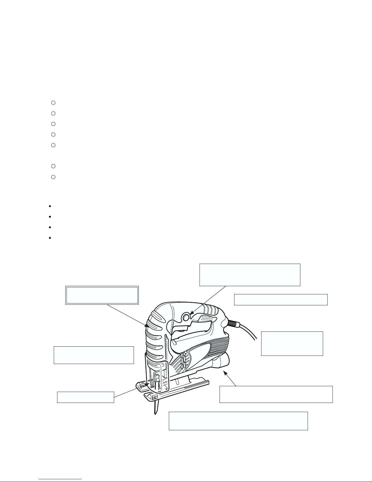
4. SELLING POINTS
Connectable to Hitachi Koki's dust collector
without use of any optional accessory
Lightweight and compact (1.5 kg)
Nonskid large soft grip
for comfortable operation
Max. cutting capacity
Wood: 65 mm
Mild steel: 6 mm
Powerful dust blowing allows
a clear view of the ink line.
Two-ball-bearing armature design for longer service
life and high efficiency motor power transmission
Easy-to-operate large trigger switch
The Model CJ 65V3 is equipped with
the speed control dial.
Guard bar for safety
Page 5
--- 2 ---
4-1. Selling Point Descriptions
(1) Higher cutting capacity
The Models CJ 65S3 and CJ 65V3 can cut wood workpieces up to 65 mm in thickness in the same manner as
7-inch circular saws. They are convenient because each model can be widely used for home-use applications
that do not require a circular saw level cutting speed, such as curved cutting (used as a jig saw) and cutting of
thick workpieces.
(2) Nonskid large soft grip
Most of the conventional soft grips cover only the handle. The Models CJ 65S3/CJ 65V3 are equipped with
the nonskid grip that largely covers both the handle and the housing (front side) to prevent slipping even if the
operator holds the Models CJ 65S3/CJ 65V3 in various ways.
(3) Large-trigger switch for more convenient operation
Adoption of a large trigger switch (room enough for two fingers) ensures easier triggering for improved control
and operation.
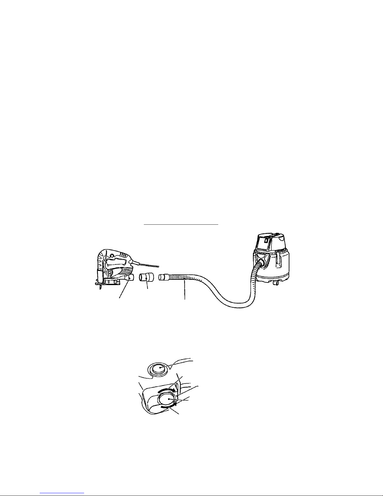
(4) Nozzle for connection with dust collector (standard accessory)
The Models CJ 65S3 and CJ 65V3 are connectable to the Hitachi Koki's dust collector through the standard
connection nozzle without use of any optional accessory for cutting operation in a clean environment.
Stopper
Adapter
Connection to dust collector
Dust collector
High speed
Adapting mouth
for dust collector
Hose
(5) Trigger switch with speed control dial (Model CJ 65V3 only)
The Model CJ 65V3 has the trigger switch with speed control dial. The triggering amount can be adjusted to
keep at a speed suitable for each job.
Low speed
Speed control dial
Switch
(6) Guard bar for safety
The guard bar prevents contact of the operator's fingers with the blade.
Page 6
--- 3 ---
214 (8-1/2")
199 (7-7/8")
67.5 (2-5/8")
1.7 (3.8 lbs.)
Maker
Length (mm)
Model
(7) Splinter guard protects easily splintered materials
Use of the splinter guard can significantly reduce cut-surface roughness of wood materials.
(8) Two-ball-bearing armature design for longer service life and high efficiency motor power transmission
The ball bearings are employed on both sides of the armature to improve durability and reliability.
(9) Lightweight and compact
Height (mm)
Weight (kg)
Width (mm)
Bearings
Dimensions
CJ 65S3/CJ 65V3
197 (7-3/4")
195 (7-3/4")
67 (2-5/8")
1.5 (3.3 lbs.)
FCJ 55/FCJ 55VA
185 (7-1/4")
186 (7-3/8")
67 (2-5/8")
1.4 (3.1 lbs.)
HITACHI
C-1
Page 7
--- 4 ---
Jig saw blade No. 31
••••••••••••••••••••••••••••••••••••••••••••••••••• •••••••••••••
1 pc.
Chip cover
••••••••••••••••••••••••••••••••••••••••••••••••••••••••••• •••••••••••••••••••
1 pc.
Splinter guard
••••••••••••••••••••••••••••••••••••••••••••••••••••••••••• ••••••••••••••
1 pc.
Hex. bar wrench
••••••••••••••••••••••••••••••••••••••••••••••••••••••••••••• •••••••••
1 pc.
879330
879331
879332
879333
879334
879335
879356
879357
879391
230
1.8
5. SPECIFICATIONS
Full-load output (A)
Number of stroke
Cord
Standard accessories
CJ 65S3
3,000/min
Performance Max. cutting thickness Wood 65 mm (2-5/8")
Mild steel plate 6 mm (1/4")
Min. cutting radius Without guide 25 mm (1")*
Trigger switch w/stopper
Type of switch
Power consumption 400 (W)
Length of stroke
18 mm (45/64")
Tilting angle of base
Right/left: 0 to 45û
Power source AC single phase 50/60 Hz
1.5 kg (3.3 lbs.) (Exclud. cord)
1.9 kg (4.2 lbs.)
Product
* Based on plate thickness of 18 mm (45/64") or less, and use of saw blade Nos. 2 and 3.
Model
Item
CJ 65V3
Type of motor Single phase AC commutator motor
Glassfiber reinforced polycarbonate resin + elastomer
Outer frame
Double insulation
Insulation
Trigger switch w/stopper
(Variable speed type w/adjust knob)
Voltage (V)
110
3.8
220
1.9
240
1.8
0 to 3,000/min
Weight
Packed
2-cord cabtire cord
Nominal sectional area: 0.75 mm2 (1.2 x 10⁻³ inch2)
Length: 2.5 m (8.2 ft.)
Optional accessories
Blade (No. 1) (5 pcs.)
Blade (No. 2) (5 pcs.)
Blade (No. 3) (5 pcs.)
Blade (No. 4) (5 pcs.)
Blade (No. 5) (5 pcs.)
Blade (No. 6) (5 pcs.)
Blade (No. 31) (5 pcs.)
Blade (No. 41) (5 pcs.)
Guide
Item
Code No.
Page 8
--- 5 ---
Cutting of wood, 18 mm (45/64") thick Cutting speed [mm (ft)/min]
Capacity
Power input
Number of stroke
Base tilting angle
Length of stroke
Weight
Actual weight
Soft grip
Dimensions
Standard accessories
Wood
Mild steel
mm
W
1/min
mm
mm
deg
kg
mm
mm
mm
Length
Height
Width
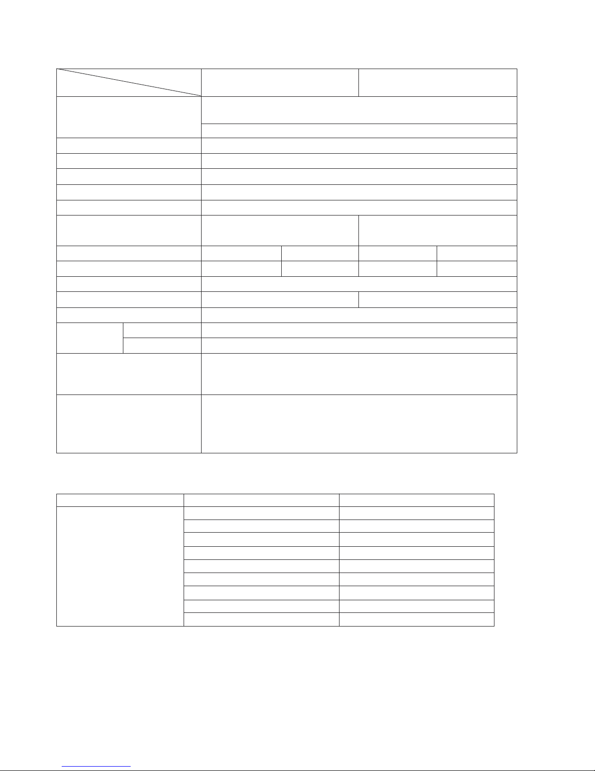
6. COMPARISONS WITH SIMILAR PRODUCTS
6-1. Specification Comparisons
HITACHI
CJ 65S3/CJ 65V3
65 (2-5/8")
67 (2-5/8")
195 (7-3/4")
197 (7-3/4")
1.5 (3.3 lbs.)
L/R 45û
1.5 (3.3 lbs.)
3000/0 to 3000
400
18 (3/4")
6 (1/4")
Jig saw blade No. 31 ... 1 pc.
Chip cover ............... 1 pc.
Splinter .................... 1 pc.
Hex. bar wrench ...... 1 pc.
* Subject to change by area.
C-1
kg
Splinter guard
Speed control dial
FCJ 55/FCJ 55VA
55 (2-5/32")
67 (2-5/8")
186 (7-3/8")
185 (7-1/4")
1.4 (3.1 lbs.)
L/R 45û
1.4 (3.1 lbs.)
3000/0 to 3000
400
18 (3/4")
3 (1/8")
Jig saw blade No. 31 ... 1 pc.
Chip cover ............... 1 pc.
Splinter .................... 1 pc.
Hex. bar wrench ...... 1 pc.
65 (2-5/8")
67.5 (2-5/8")
199 (7-7/8")
214 (8-1/2")
1.7 (3.8 lbs.)
L/R 45û
1.7 (3.8 lbs.)
3100
450
22 (7/8")
6 (1/4")
Jig saw blade ........ 1 pc.
Chip cover ............. 1 pc.
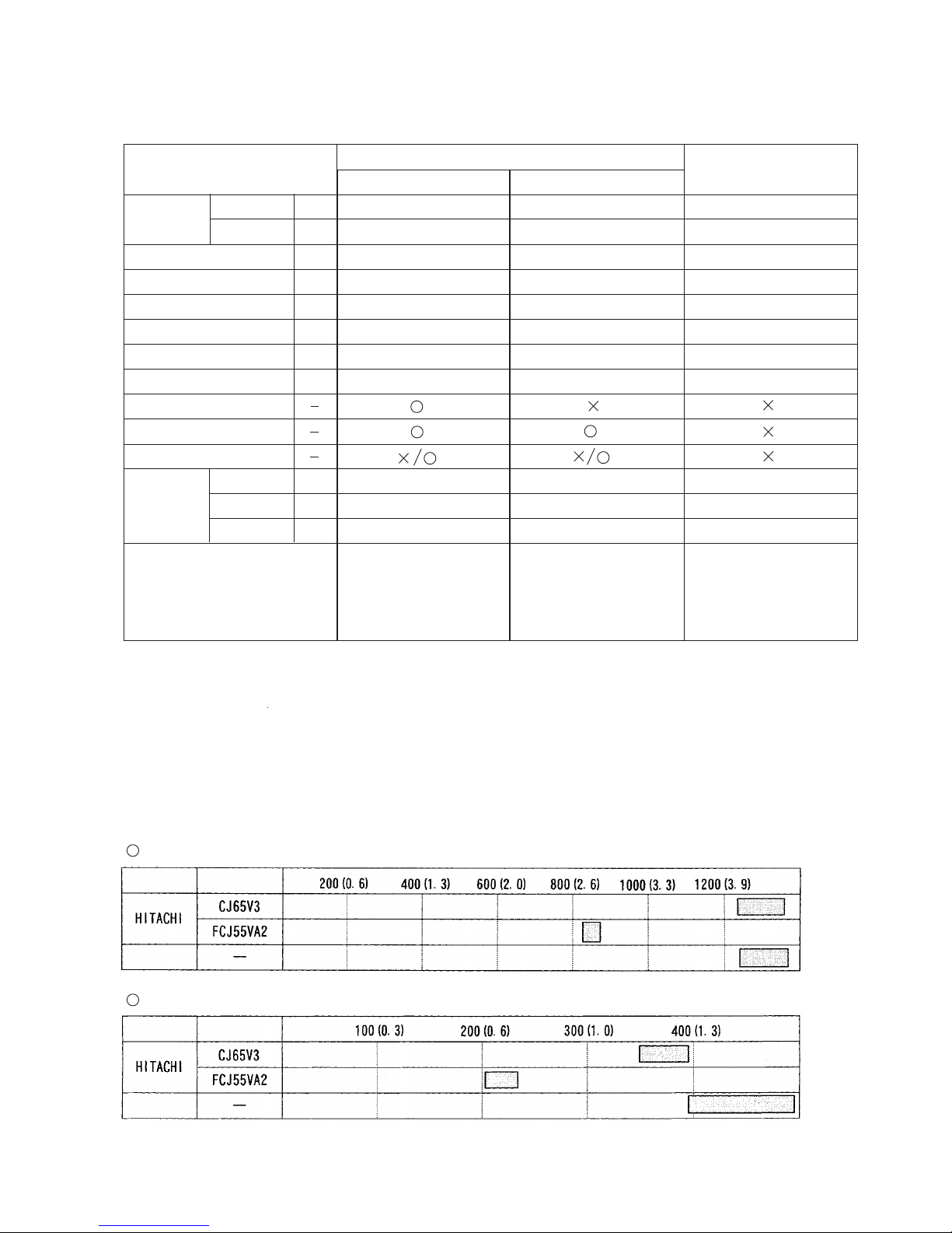
6-2. Comparison of Cutting Speeds
Cutting speeds fluctuate widely depending on cutting conditions. The data in the tables below were obtained
while minimizing fluctuations as much as possible. Also, all plunger speeds were set to full (maximum speed),
and blades recommended by each manufacturer for the materials cut were used. Thrust (pressing force) was
limited to 2 kg, within the range of normal cutting thrust.
Cutting of soft steel plate, 2 mm (5/64") thick Cutting speed [mm (ft)/min]
Maker
Model
C-1
Maker
Model
C-1
Page 9
--- 6 ---
7. PRECAUTIONS IN SALES PROMOTION
In the interest of promoting the safest and most efficient use of the Models CJ 65S3 and CJ 65V3 Jig Saws by all
of our customers, it is very important that at the time of sale the salesperson carefully ensures that the buyer
seriously recognizes the importance of the contents of the Handling Instructions, and fully understands the
meaning of the precautions listed on the Caution Plate attached to each tool.
7-1. Handling Instructions
Although every effort is made in each step of design, manufacture, and inspection to provide protection against
safety hazards, the dangers inherent in the use of any electric tool cannot be completely eliminated. Accordingly,
general precautions and suggestions for the use of electric power tools, and specific precautions and
suggestions for the use of the electric jig saw are listed in the Handling Instructions to enhance the safe, efficient
use of the tool by the customer. Salespersons must be thoroughly familiar with the contents of the Handling
Instructions to be able to offer appropriate guidance to the customer during sales promotion.
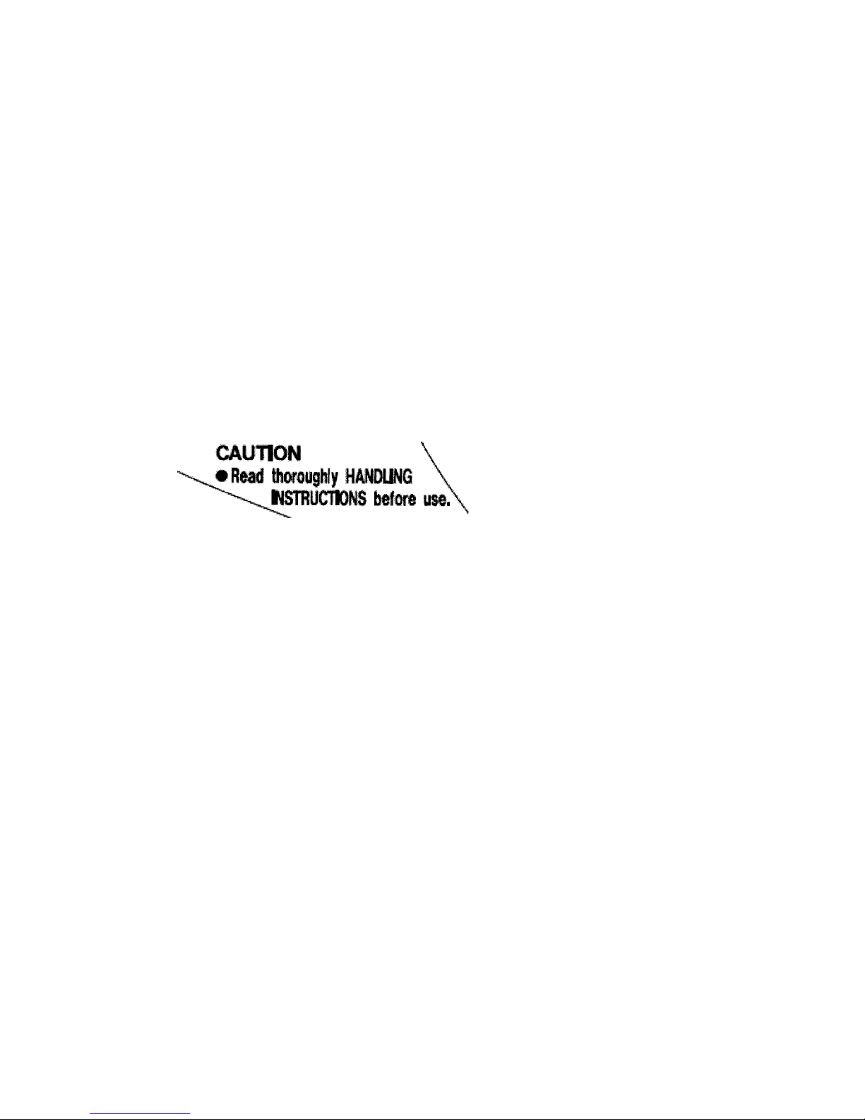
7-2. Cautions on the Name Plate
Each tool is provided with a Name Plate which lists the following basic safety precautions in the use of the tool.
7-3. Overload Durability Characteristics
The Models CJ 65S3 and CJ 65V3 have been designed specifically for home use, and their ability to withstand
overload is inferior to jig saws for professional use. Because oleo metal and polycarbonate resin are used for the
bearings and external components respectively, heat generation is high and heat radiation is inferior. Customers
should be cautioned that use of these models for professional level work could result in melting of the oleo metal
components and possible serious damage to other sections.
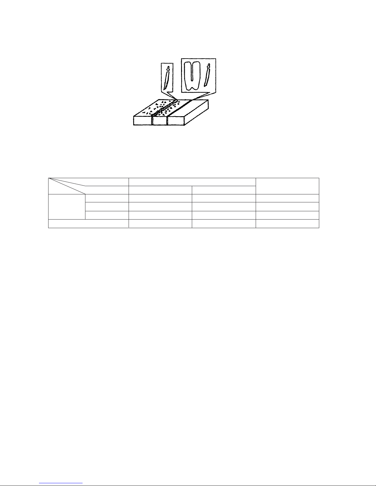
7-4. Use of Guide Roller
The new models are equipped with a guide roller which supports the load applied on the blade and bearing during
cutting operation, and helps prevent breakage of the blade and early wear of the bearing. When using the guide
roller, users should be instructed to pay particular attention to the following items described in the Instruction
Manual.
(1) Use a blade having a straight back portion (the back of the blade that contacts the guide roller) which is 50 mm
(2") or more in length (see Fig. a.). If a blade with an inclined back portion (see Fig. b.) is used, it will cause
excessive force on the plunger assembly, resulting in early malfunction of the bearing and the guide roller.
(2) The guide roller should be mounted so that its roller gently contacts the back of the blade. If the roller is
pressed too strongly against the blade during use, it will cause early malfunction of the bearing and other
parts, as described in paragraph (1) above.
Page 10

--- 7 ---
(3) When cutting thick plate materials which apply a particularly heavy load on the blade, be sure to mount the
guide roller before the cutting operation. As failure to mount the guide roller before cutting such materials will
result in early malfunction of the bearing portion, particular precaution is necessary.
Use a blade with a straight back
portion 50 mm (2") or more in length.
Do not use a blade with an inclined back.
Fig. a
Fig. b
8. BLADES
8-1. Applicable Blade
NOTE: As illustrated on the right, the guide roller can become jammed in the recessed portion
of the jig saw blade, causing damage to the blade and/or guide roller. Accordingly, it is
necessary to withdraw the guide roller so that it will not contact the blade. In addition,
the thickness of the jig saw blade must be 1.3 mm (3/64") or less.
Maker
Blade shape and dimensions
Installation
HITACHI
C-1
8 mm
(5/16")
6.2
(15/64")
7
(9/32")
6.2
8
Page 11

--- 8 ---
9. PRECAUTIONS IN DISASSEMBLY AND REASSEMBLY
The [Bold] numbers in the descriptions below correspond to the part numbers in the Model CJ 65V3 Parts List.
The disassembly and reassembly procedures are the same for the Model CJ 65S3, with the exception of the
switch and the wiring diagrams. Where the part numbers are different, those in parentheses are for the Model
CJ 65S3.
9-1. Disassembly
9-1-1. Removal of the Chip Cover [1]
In the same manner as it is slid up and down for positioning, slide the Chip
Cover [1] upward to remove it from the main body.
9-1-2. Removal of the Guard Bar [2]
Stretch both ends of the Guard Bar [2] and remove it from the main body.
9-1-5. Disassembly of the plunger
Loosen the Seal Lock Hex. Socket Hd. Bolt M3 x 8 [25] and remove the Blade Holder [22], Plunger Holder [21]
and Felt [24].
9-1-6. Disassembly of the armature and the stator
(1) From housing (A) of Housing (A).(B) Set [4], remove the Brush Holders [15], and take out the Carbon
Brushes [14] (two pieces).
(2) From housing (A) of Housing (A).(B) Set [4], remove the Holder [29], Stator Ass'y [33] and Armature [31] in
a single body. Then separate the individual parts.
9-1-3. Disassembly of Housing (B)
(1) Remove the Hex. Socket Hd. Bolt M4 x 16 [19] with the Hex. Bar Wrench 3 mm [501] (standard accessory),
and remove the Base [11] and the Roller Holder [17].
(2) Remove the seven Tapping Screws (W/Flange) D4 x 20 (Black) [7], and take off housing (B) of Housing (A).(B)
Set [4].
9-1-4. Disassembly of the gear
(1) From housing (A) of Housing (A).(B) Set [4], take out the Plunger [23] and the Plunger Holder [21] (two
pieces).
(2) Lift the Gear [27] upward and remove it from the Holder [29]. Washer (C) [28] can be removed at the same
time.
How to remove the chip cover
Holder [29]
Gear removal procedure
Lift upward.
Gear [27]
Housing (A)
Page 12

--- 9 ---
9-1-7. Removal of the Switch (1P Pillar Type) [5]
Loosen the cord mounting screws of the Switch (1P Pillar Type) [5] and pull out the cord.
Cord mounting screws
Cord
To remove the internal wires of the Stator Ass'y [33] and the Noise Suppressor [6], insert the small-diameter
screwdriver or a pin into the concave next to each terminal and pull the internal wire lightly.
Concave
Concave
Page 13

--- 10 ---
9-2. Reassembly
Reassembly can be accomplished by following the disassembly procedures in reverse. However, special attention
should be given to the following items.
9-2-1. Wiring Connection
Referring to the wiring diagrams and leadwire arrangements in item 9-5.
9-2-2. Reassembly of the armature and the stator
(1) Press-fit the Ball Bearing 608VVC2PS2L [30] and the Ball Bearing 626VVC2PS2L [32] onto the Armature [31].
Stop press-fitting when the Ball Bearing 608VVC2PS2L [30] comes in contact with the fan. With vernier
calipers or a similar tool, check that the press-fit dimension is 119.9 . As excessive press-fitting can cause
deformation or other damage to the fan, particular attention is required. Also, if press-fitting is insufficient, it
will cause loss of thrust of the Armature [31], resulting heat generation. Accordingly, press-fit the Ball Bearing
626VVC2PS2L [32] until it butts against the stepped portion of the shaft.
(2) Insert the Armature [31] into the Holder [29] and put the assembly into the Stator Ass'y [33].
Armature, stator and holder assembly sequence
Fan
Holder [29]
Armature [31]
Stator Ass'y [33]
Ball Bearing
608VVC2PS2L
[30]
Difference of shaft
Ball Bearing 626VVC2PS2L [32]
9-2-3. Others
(1) When re-mounting housing (A) of Housing (A).(B) Set [4], be very careful to ensure that the leadwires are not
excessively slack, and that they are not pinched between components during reassembly.
(2) When reassembling the Chip Cover [1] onto the main body, be sure it is mounted in the correct direction.
- 0.3
0
Chip Cover [1]
The antislip grooved portion is at the top.
119.9
- 0.3
0
Page 14

--- 11 ---
9-4. Tightening Torques
Tapping Screw (W/Flange) D4 x 20
Tapping Screw (W/Flange) D4 x 16
Hex. Socket Hd. Bolt M3 x 8
Hex. Socket Hd. Bolt M4 x 8
Hex. Socket Hd. Bolt M4 x 16
2.0 0.5 N•m (20 5 kgf•cm)
2.0 0.5 N•m (20 5 kgf•cm)
1.5 0.5 N•m (15 5 kgf•cm)
2.0 0.5 N•m (20 5 kgf•cm)
2.0 0.5 N•m (20 5 kgf•cm)
9-3. Lubrication
Housing (A) and housing (B): 13 g each
Tooth section of the Gear [27]
Pinion section of the Armature 220V --- 230V [31]
Contact section of the Plunger [23] and the Plunger Holder [21]
Pin of the Holder [29]
Washer (C) [28]
Inside diameter of the Gear [27] and the sliding surfaces of the
Connecting Piece [26] and Washer (C) [28]
Inside and outside diameters of the Connecting Piece [26]
Hitachi Motor Grease No. 29
ATTOLUB MS No. 2
Page 15

--- 12 ---
9-5. Wiring Diagram
(1) Model CJ 65S3
(a) Products with noise suppressor
(b) Products without noise suppressor
Page 16

--- 13 ---
(2) Model CJ 65V3
(a) Products with noise suppressor
(b) Products without noise suppressor
9-6. Connection to the Switch
Solder the tips of the internal wires of the Stator Ass'y [33] and the Noise Suppressor [6]. Then insert them into
the terminals of the Switch (1P Pillar Type) [5].
Internal wire
Solder
7
Page 17

--- 14 ---
9-7. Insulation Tests
On completion of disassembly and repair, measure the insulation resistance and conduct dielectric strength test.
9-8. No-Load Current Values
After 30 minutes of no-load operation, current values should be as follows:
110 V
115 V
120 V
127 V
Less than 1.8 A
220 V
.........
Less than 1.0 A
230 V
.........
Less than 0.9 A
240 V
.........
Less than 0.9 A
Page 18

--- 15 ---
10. STANDARD REPAIR TIME (UNIT) SCHEDULES
MODEL 10 20 30 40
Fixed
Variable
CJ 65V3
Work Flow
Housing
(A).(B) Set
Plunger Holder
Plunger
Connecting
Piece
Gear
Holder
Felt
Blade Holder
Chip Cover
Guard Cover
60 min.
50
General Assembly
Base
Roller Holder
Stator Ass'y
Armature
Ball Bearing
(608VV)
Ball Bearing
(626VV)
Switch
Cord Armor
Cord Armor
Carbon Brush
x 2
CJ 65S3
Page 19

ELECTRIC TOOL PARTS LIST
LIST NO. E510
JIG SAW
Model CJ 65S3
2005 • 10 •12
(E1)
Hitachi Power Tools
1
2
4
5
6
7
8
9
10
12
11
3
14
15
16
17
18
20
21
23
26
27
28
29
30
31
32
33
34
501
19
502
503
12
22
21
24
25
13
Page 20

*
ALTERNATIVE PARTS--- 2 ---
ITEM
NO.
CODE NO.
DESCRIPTION REMARKS
NO.
USED
PARTS
10 -- 05
CJ 65S3
1 325-163 CHIP COVER 1
2 325-164 GUARD BAR 1
3 HITACHI LABEL 1
4 325-167 HOUSING (A).(B) SET 1
5 323-575 SWITCH (1P PILLAR TYPE) 1
6 930-039 NOISE SUPPRESSOR 1
7 301-653
TAPPING SCREW (W/FLANGE) D4X20 (BLACK) 7
8 NAME PLATE 1
9 960-266 CORD CLIP 1
10 984-750 TAPPING SCREW (W/FLANGE) D4X16 2
11 325-161 BASE 1
12 949-811 HEX. SOCKET HD. BOLT M4X8 (10 PCS.) 2
13 962-991 PLATE NUT 1
14 999-041 CARBON BRUSH (1 PAIR) 2
15 930-483 BRUSH HOLDER 2
16 930-487 CORD ARMOR D8.2 1
17 325-162 ROLLER HOLDER 1
18 323-210 BOLT WASHER M4 (BLACK) 1
19 949-754 HEX. SOCKET HD. BOLT M4X16 (10 PCS.) 1
20 500-409Z CORD 1 (CORD ARMOR D8.2)
21 325-159 PLUNGER HOLDER 2
22 325-247 BLADE HOLDER 1
23 325-246 PLUNGER 1
24 325-248 FELT 1
25 325-241
SEAL LOCK HEX. SOCKET HD. BOLT M3X8
2
26 325-158 CONNECTING PIECE 1
27 325-157 GEAR 1
28 991-733 WASHER (C) 1
29 325-155 HOLDER 1
30 608-VVM BALL BEARING 608VVC2PS2L 1
31 360-724E ARMATURE 220V-230V 1
32 626-VVM BALL BEARING 626VVC2PS2L 1
33 340-631E STATOR ASS’Y 220V-230V 1 INCLUD. 34
34 960-356 TERMINAL (A) M3.5 (10 PCS.) 2
Page 21

*
ALTERNATIVE PARTS --- 3 ---10 -- 05
STANDARD ACCESSORIES
OPTIONAL ACCESSORIES
ITEM
NO.
CODE NO.
DESCRIPTION REMARKS
NO.
USED
ITEM
NO.
CODE NO.
DESCRIPTION
REMARKS
NO.
USED
CJ 65S3
501 943-277 HEX. BAR WRENCH 3MM 1
502 305-810 TABLE INSERT 1
503 879-356 JIG SAW BLADES NO. 31 (5 PCS.) 1
601 879-330 JIG SAW BLADES NO. 1 (5 PCS.) 1
602 879-331 JIG SAW BLADES NO. 2 (5 PCS.) 1
603 879-332 JIG SAW BLADES NO. 3 (5 PCS.) 1
604 879-333 JIG SAW BLADES NO. 4 (5 PCS.) 1
605 879-334 JIG SAW BLADES NO. 5 (5 PCS.) 1
606 879-335 JIG SAW BLADES NO. 6 (5 PCS.) 1
607 879-357 JIG SAW BLADE NO. 41 (5 PCS.) 1
608 879-391 GUIDE FOR JIG SAW 1
Page 22

--- 4 ---
ITEM
NO.
CODE NO.
DESCRIPTION REMARKS
NO.
USED
10 -- 05
CJ 65S3
Printed in Japan
(051012N)
Page 23

ELECTRIC TOOL PARTS LIST
LIST NO. E509
JIG SAW
Model CJ 65V3
2005 • 10 •12
(E1)
Hitachi Power Tools
1
2
4
5
6
7
8
9
10
12
13
11
3
14
15
16
17
18
20
21
23
26
27
28
29
30
31
32
33
34
501
19
502
503
12
22
21
24
25
Page 24

*
ALTERNATIVE PARTS--- 2 ---
ITEM
NO.
CODE NO.
DESCRIPTION REMARKS
NO.
USED
PARTS
10 -- 05
CJ 65V3
1 325-163 CHIP COVER 1
2 325-164 GUARD BAR 1
3 HITACHI LABEL 1
4 325-167 HOUSING (A).(B) SET 1
5 323-086 SWITCH (1P PILLAR TYPE) 1
6 930-039 NOISE SUPPRESSOR 1
7 301-653
TAPPING SCREW (W/FLANGE) D4X20 (BLACK) 7
8 NAME PLATE 1
9 960-266 CORD CLIP 1
10 984-750 TAPPING SCREW (W/FLANGE) D4X16 2
11 325-161 BASE 1
12 949-811 HEX. SOCKET HD. BOLT M4X8 (10 PCS.) 2
13 962-991 PLATE NUT 1
14 999-041 CARBON BRUSH (1 PAIR) 2
15 930-483 BRUSH HOLDER 2
16 930-487 CORD ARMOR D8.2 1
17 325-162 ROLLER HOLDER 1
18 323-210 BOLT WASHER M4 (BLACK) 1
19 949-754 HEX. SOCKET HD. BOLT M4X16 (10 PCS.) 1
20 500-409Z CORD 1
21 325-159 PLUNGER HOLDER 2
22 325-247 BLADE HOLDER 1
23 325-246 PLUNGER 1
24 325-248 FELT 1
25 325-241
SEAL LOCK HEX. SOCKET HD. BOLT M3X8
2
26 325-158 CONNECTING PIECE 1
27 325-157 GEAR 1
28 991-733 WASHER (C) 1
29 325-155 HOLDER 1
30 608-VVM BALL BEARING 608VVC2PS2L 1
31 360-724E ARMATURE 220V-230V 1
32 626-VVM BALL BEARING 626VVC2PS2L 1
33 340-631E STATOR ASS’Y 220V-230V 1 INCLUD. 34
34 960-356 TERMINAL (A) M3.5 (10 PCS.) 2
Page 25

*
ALTERNATIVE PARTS --- 3 ---10 -- 05
STANDARD ACCESSORIES
OPTIONAL ACCESSORIES
ITEM
NO.
CODE NO.
DESCRIPTION REMARKS
NO.
USED
ITEM
NO.
CODE NO.
DESCRIPTION
REMARKS
NO.
USED
CJ 65V3
501 943-277 HEX. BAR WRENCH 3MM 1
502 305-810 TABLE INSERT 1
503 879-356 JIG SAW BLADES NO. 31 (5 PCS.) 1
601 879-330 JIG SAW BLADES NO. 1 (5 PCS.) 1
602 879-331 JIG SAW BLADES NO. 2 (5 PCS.) 1
603 879-332 JIG SAW BLADES NO. 3 (5 PCS.) 1
604 879-333 JIG SAW BLADES NO. 4 (5 PCS.) 1
605 879-334 JIG SAW BLADES NO. 5 (5 PCS.) 1
606 879-335 JIG SAW BLADES NO. 6 (5 PCS.) 1
607 879-357 JIG SAW BLADE NO. 41 (5 PCS.) 1
608 879-391 GUIDE FOR JIG SAW 1
Page 26

--- 4 ---
ITEM
NO.
CODE NO.
DESCRIPTION REMARKS
NO.
USED
10 -- 05
CJ 65V3
Printed in Japan
(051012N)
Page 27

 Loading...