

Page 1
Read through carefully and understand these instructions before use.
Diese Anleitung vor Benutzung des Werkzeugs sorgfältig durchlesen und verstehen.
Lire soigneusement et bien assimiler ces instructions avant usage.
Prima dell’uso leggere attentamente e comprendere queste istruzioni.
Deze gebruiksaanwijzing s.v.p. voor gebruik zorgvuldig doorlezen.
Leer cuidadosamente y comprender estas instrucciones antes del uso.
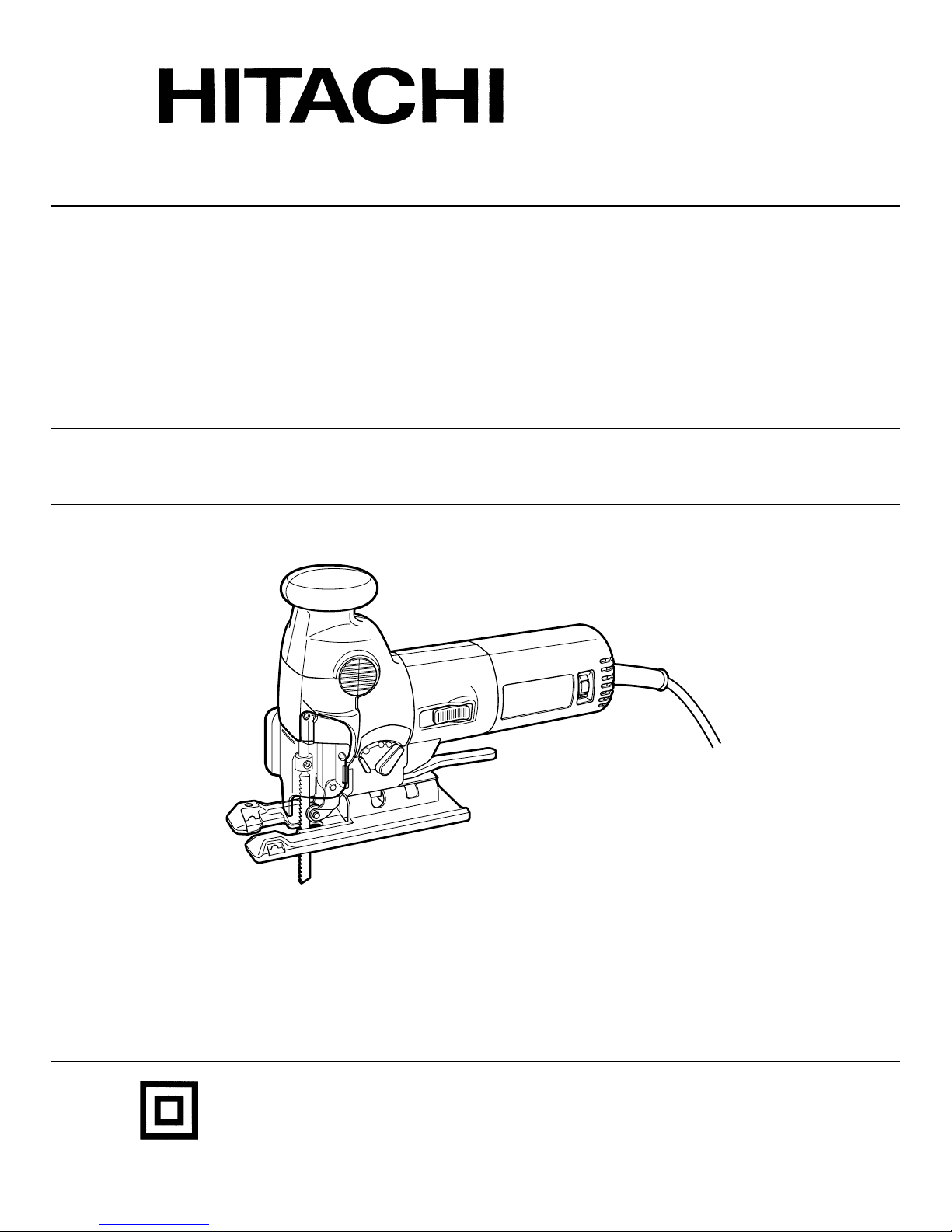
JIG SAW
STICHSÄGE
SCIE SAUTEUSE
SEGHETTO ALTERNATIVO
DECOUPEERZAAGMACHINE
SIERRA CALADORA
CJ 110VA
Handling instructions
Bedienungsanleitung
Mode d’emploi
Istruzioni per l’uso
Gebruiksaanwijzing
Instrucciones de manejo
Page 2
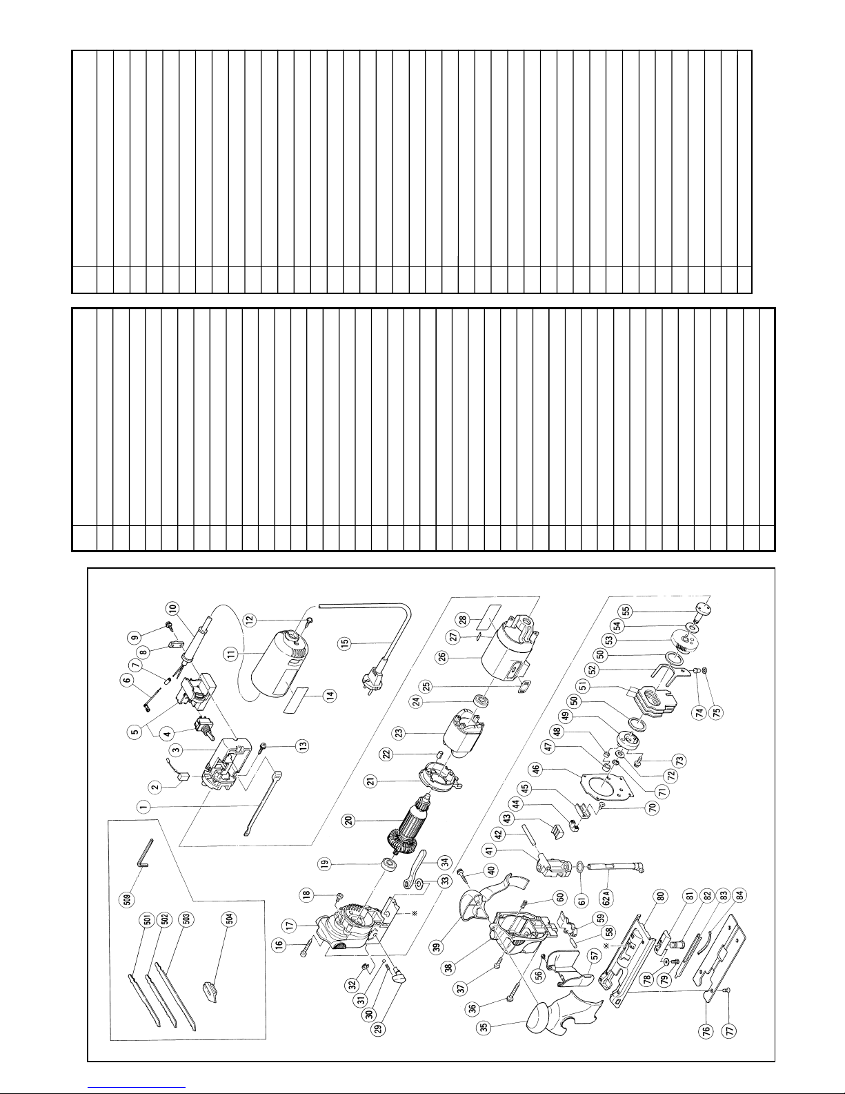
43 Rubber Cushion
44 Connector Holder
45 Connector
46 Packing
47 Connecting Piece
48 Needle Bearing (NTN K6
×
8
×
8T2)
49 Weight Holder
50 Washer (A)
51 Balance Weight
52 Orbital Cam
53 Gear
54 Washer (A)
55 Spindle
56 Special Screw M3
×
4
57 Ship Cover
58 Needle D5
×
19.8
59 Guide Roller
60 Spging
61 O-Ring (P-16)
62A Plunger
70 Seal Lock Flat Hd. Screw M4
×
10
71 Retaining Ring For D8 Shaft
72 Wahser (B)
73
Hex. Socket Hd. Bolt (W/Flange)
M5
×
12
74 Orbital Pin
75 Felt
76 Sub Base
77 Nylock Flat Hd. Screw M5
×
40
78 Washer
79 Hex. Socket Hd. Bolt M4
×
8
80 Base
81 Base Locker
82 Base Bolt
83 Spacer
84 Plate Spring
501 Blade No.42
502 Blade No.46
503 Blade No.41
504 Splinter Guard
509 Hex. Bar Wrench
Part Name
1 Slide Bar
2 Carbon Brush
3 Wiring Block (A)
4 Switch
5 Wiring Block (B) Ass’y
6 Internal Wire
7 Connector (50096)
8 Cord Clip
9 Tapping Screw (W/Flange) D4×16
10 Cord Armor
11 Tail Cover
12 Tapping Screw (W/Flange) D4×12
13 Tapping SCrew (W/Flange) D4×16
14 HITACHI Label
15 Cord
16 Tapping Screw D4×30
17 Gear Cover
18
Hex. Socket Hd. Bolt (W/Flange)
M4×6
19 Ball Bearing (608DDW)
20 Armature
21 Fan Guide Ass’y
22 Rubber Bushing
23 Stator
24 Ball Bearing (608DDMC2EPS2S)
25 Slide Knob
26 Housing
27 Label (CE Mark) (A)
28 Name Plate
29 Change Knob
30 Sping (C)
31 Steel Ball
32
Retaining Ring (E-Type) For D5 Shaft
33 Washer
34 Base Handle
35 Cover (A)
36 Tapping Screw (W/Flange) D4×65
37 Machine Screw M4×16
38 Upper Cover
39 Cover (B)
40 Tapping Screw (W/Flange) D4
×
25
41 Plunger Holder Ass’y
42 Pin D6
×
47
Part Name
Item
No.
Item
No.
Parts are subject to possible modification
without notice due to improvements.
The exploded assembly drawing should be used only for authorized service center.
Page 3
1
3
1
4
5
6
7
8
1
2
3
4
8
9
7
A
C
D
L
K
J
I
2
B
E
F
E
G
H
:
E
Page 4
2
9
10
11
12
13
14
15
L
M
N
O
J
P
T
S
F
E
U
7mm
14mm
46
R
Q
D
6
:
6
5
16
D
Page 5

3
Italiano Nederlands Español
1 Raccoglitrucioli Spaankast Cubierta de virutas
2 Aprire Open Apertura
3 Chiudere Dicht Cierre
4 Vite di fissaggio della lama Stelschroef voof zaagblad Tornillo de ajuste de la cuchilla
5 Scanalatura Groef Ranura
6 Chiave esagonale maschia Inbussleutel Ilave macho hexagonal
7 Anello di fissaggio Stelring Anillo de ajuste
8 Rullo Geleiderol Rodillo
9 Direzione di inserimento Richting voor insteken Sentido de inserción
0 Lama Zaagblad Cuchilla
A Selettore Schijf Selector
B Rotella di cambio Omstelknop Perilla de cambio
C Pará-schegge Anti-splinterstuk Protector contra astillas
D Base Zaagtafel Base
E Bullone a manopola Knopbout Perno de perilia
F Guida rettilinea Rechtgeleider Guia rectilínea
G Guida circolare Cirkegeleider Guía circular
H Centro della guida Geleider midden Centro de la guía
I Scala parte semicircolare Halve-cirkel van schaal Escala de parte semicircular
J Fessura parte semicircolare Halve-cirkel van opening Ranura de parte semicircular
K
Segno a sul coperchio ingranaggi V ersn
ellingafdekking -markering
Marca en de la cubierta de engranajes
L Maniglia della base Basishendel Asa de la base
M Allentare Losdraaien Aflojar
N Stringere Aandraaien Apretar
O Circa 90 gradi Ongeveer 90 graden Aprox. 90 grados
P Segno sul coperchio ingranaggi Versnellingafdekking markering Marca de la cubierta de la base
Q Limite di usura Slijtagegrens Límite de uso
R No. della spazzola di carbone Nr. van de koolborstel No. del escobilla
S Molla a spirale Spiraalveer Resorte espiral
T Porfa-spazzola Borstelhouder Sujetador de carbón
U Spazzola di carbone Koolborstel Escobilla
English Deutsch Français
1 Chip cover Schnipseldeckel Couvercle d’éclats
2 Open Öffnen Ouvrir
3 Close Schließen Fermer
4 Blade set screw Klemmschraube für das Sägeblatt Vis de fixation de la lame
5 Groove Kerbe Rainure
6 Hexagonal bar wrench Sechskantinnenschüssel Clef à six pans
7 Set ring Einstellring Bague de fixation
8 Roller Führungsrolle Rouleau
9 Insert direction Einschubrichtung Sens d’insertion
@ Blade Blatt Lame
A Dial Skalenscheibe Cadran
B Change knob Wechselring Bouton de changement
C Splinter guard Splitterschutz Anti-éclats
D Base Grundplatte Base
E Knob bolt Knopfschraube Boulon bouton
F Rectilinear guide Gradschneider Guide rectilinéaire
G Circular guide Kreischneider Guide circulaire
H Guide center Führungsmitte Centre de guidage
I Semi-circular part scale Halbkreisförmige Skala Echelle de section semi-circulaire
J Semi-circular part slot Halbkreisförmiger Schlitz Fente de section semi-circulaire
K Gear cover -mark
-Markierung an der Getriebeabdeckung
Repère en du couvercle de réducteur
L Base handle Basishandgriff Poignée de socle
M Loosen Lösen Desserrer
N Tighten Anziehen Serrer
O Approx. 90 degrees Etwa 90 Grad Environ 90 degrés
P Gear cover mark Getriebeabdeckungsmarkierung
Repère du couvercle de réducteur
Q Wear limit Verschleißgrenze Limite d’usure
R No. of carbon brush Nr. de Kohlebürste No. de balai en carbone
S Spiral spring Spiralfeder Ressort en spirale
T Brush holder Bürstenhalter Support du balai
U Carbon brush Kohlebürste Balai en carbon
Page 6

English
4
GENERAL OPERATIONAL PRECAUTIONS
WARNING! When using electric tools, basic safety
precautions should always be followed to reduce the risk
of fire, electric shock and personal injury, including the
following.
Read all these instructions before operating this product
and save these instructions.
For safe operations:
1. Keep work area clean. Cluttered areas and benches
invite injuries.
2. Consider work area environment. Do not expose
power tools to rain. Do not use power tools in
damp or wet locations. Keep work area well lit.
Do not use power tools where there is risk to
cause fire or explosion.
3. Guard against electric shock. Avoid body contact
with earthed or grounded surfaces. (e.g. pipes,
radiators, ranges, refrigerators).
4. Keep children away. Do not let visitors touch the
tool or extension cord. All visitors should be kept
away from work area.
5. Store idle tools. When not in use, tools should
be stored in a dry, high or locked up place, out
of reach of children.
6. Do not force the tool. It will do the job better and
safer at the rate for which it was intended.
7. Use the right tool. Do not force small tools or
attachments to do the job of a heavy duty tool.
Do not use tools for purposes not intended; for
example, do not use circular saw to cut tree
limbs or logs.
8. Dress properly. Do not wear loose clothing or
jewellery, they can be caught in moving parts.
Rubber gloves and non-skid footwear are
recommended when working outdoors. Wear
protecting hair covering to contain long hair.
9. Use eye protection. Also use face or dust mask
if the cutting operation is dusty.
10. Connect dust extraction equipment.
If devices are provided for the connection of dust
extraction and collection facilities ensure these are
connected and properly used.
11. Do not abuse the cord. Never carry the tool by
the cord or yank it to disconnect it from the
receptacle. Keep the cord away from heat, oil and
sharp edges.
12. Secure work. Use clamps or a vise to hold the
work. It is safer than using your hand and it frees
both hands to operate tool.
13. Do not overreach. Keep proper footing and balance
at all times.
14. Maintain tools with care. Keep cutting tools sharp
and clean for better and safer performance. Follow
instructions for lubrication and changing
accessories. Inspect tool cords periodically and if
damaged, have it repaired by authorized service
center. Inspect extension cords periodically and
replace, if damaged. Keep handles dry, clean, and
free from oil and grease.
15. Disconnect tools. When not in use, before servicing,
and when changing accessories such as blades,
bits and cutters.
16. Remove adjusting keys and wrenches. Form the
habit of checking to see that keys and adjusting
wrenches are removed from the tool before turning
it on.
17. Avoid unintentional starting. Do not carry a
plugged-in tool with a finger on the switch. Ensure
switch is off when plugging in.
18. Use outdoor extension leads. When tool is used
outdoors, use only extension cords intended for
outdoor use.
19. Stay alert. Watch what you are doing. Use common
sense. Do not operate tool when you are tired.
20. Check damaged parts. Before further use of the
tool, a guard or other part that is damaged should
be carefully checked to determine that it will
operate properly and perform its intended function.
Check for alignment of moving parts, free running
of moving parts, breakage of parts, mounting and
any other conditions that may affect its operation.
A guard or other part that is damaged should be
properly repaired or replaced by an authorized
service center unless otherwise indicated in this
handling instructions. Have defective switches
replaced by an authorized service center. Do not
use the tool if the switch does not turn it on and
off.
21. Warning
The use of any accessory or attachment, other
than those recommended in this handling
instructions, may present a risk of personal injury.
22. Have your tool repaired by a qualified person.
This electric tool is in accordance with the relevant
safety requirements. Repairs should only be carried
out by qualified persons using original spare parts.
Otherwise this may result in considerable danger
to the user.
PRECAUTIONS ON USING JIG SAW
This machine employs a high-power motor. If the machine
is used continuously at low speed, an extra load is applied
to the motor which can result in motor seizure. Always
operate the power tool so that the blade is not caught by
the material during operation. Always adjust the blade
speed to enable smooth cutting.
Page 7

5
English
STANDARD ACCESSORIES
(1) Blades (No. 41, No. 42, No. 46) ................ 1 each
Refer to Table 1 for use of the blades.
(2) Hexagon bar wrench ............................................... 1
(3) Splinter guard ........................................................... 1
Standard accessories are subject to change without notice.
OPTIONAL ACCESSORIES ... Sold separately
(1) Various types of blades
Refer to Table 1 for use of the blades.
(2) Dust collecter
(3) Rectilinear guide
(4) Circular guide
(5) Bench stand (Model TR12-B)
Optional accessories are subject to change without notice.
APPLICATIONS
䡬 Cutting various lumber and pocket cutting
䡬 Cutting mild steel plate, aluminum plate, and copper
plate
䡬 Cutting synthetic resins, such as phenol resin and
vinyl chloride
䡬 Cutting thin and soft construction materials
䡬 Cutting stainless steel plate (with No. 95, No. 96
or No. 97 blade).
PRIOR TO OPPERATION
1. Power source
Ensure that the power source to be utilized conforms
to the power requirements specified on the product
nameplate.
2. Power switch
Ensure that the power switch is in the OFF position.
If the plug is connected to a receptacle while the
power switch is in the ON position, the power tool
will start operating immediately, which could cause
a serious accident.
3. Extension cord
When the work area is removed from the power
source, use an extension cord of sufficient thickness
and rated capacity. The extension cord should be
kept as short as practicable.
4. Mounting the blade
(1) Open the chip cover. (Fig. 1)
(2) Use the accessory hexagonal bar wrench to loosen
the blade set screw on the set ring, as shown in
Fig. 2.
(3) Fully insert the blade mounting portion into the set
ring with the rear face of the blade engaged with
the groove and tighten the set screw. (Fig. 2).
(4) Close the chip cover. (Fig. 1).
NOTE:
Loosened set screw may cause the blade to be
damaged. Always ensure that the set screw is
securely tightened. Always ensure that the mounting
portion of the set ring is clean and claer of sawdust
to ensure proper blade mounting and set screw
clamping.
5. Adjusting the blade operating speed
The CJ110VA is equipped with the electric control
circuit which enables stepless speed control. To
adjust the speed, turn the dial shown in Fig. 3.
When the dial is set to “1”, the jig saw operates
at the minimum speed (700 /min). When the dial
set to “5”, the jig saw operates at the maximum
speed (3200 /min). Adjust the speed according to
the material to be cut and working efficiency.
CAUTION
At low speed (dial setting: 1 or 2) do not cut a wood
with a thickness of more than 10 mm or metal with
a thickness of more than 1 mm.
6. Adjusting the orbital operation
(1) This machine employs orbital operation which moves
the blade back and forth, as well as up and down.
Set the change knob shown in Fig. 4 to “0” to
eliminate the orbital operation (the blade moves
only up and down). The orbital operation can be
selected in 4 steps from “0” to “III”.
(2)
For the hard material, such as a steel plate, etc.,
decrease the o3rbital operation. For the soft material,
such as lumber, plastic, etc., increase the orbital
operation to increase work efficiency. To cut the
material accurately, decrease the orbital operation.
7. Cutting stainless steel plates
The CJ110VA model, when used with the No. 95,
No. 96 or No. 97 blade, can cut stainless steel
plates. Carefully read “Concerning cutting of stainless
steel plates” for proper operation.
8. Splinter guard
Using the splinter guard when cutting wood
materials will reduce splintering of cut surfaces.
Insert the splinter guard in the space between the
base and sub-base, push forward and attach (see
Fig. 5).
SPECIFICATIONS
Voltage (by areas)* (110V, 115V, 120V, 127V, 220V, 230V, 240V)
Power Input* 570W
Max. Cutting Depth
Wood 100 mm
Mild Steel 10 mm
No-Load Speed 700—3200/min.
Stroke 26 mm
Min. Cutting Radius 25 mm
Weight (without cord) 2.4kg
*Be sure to check the nameplate on product as it is subject to change by areas.
Page 8

English
6
CUTTING
CAUTIONS
䡬 While sawing, the base must be firmly in contact
with the material surface, and the blade must be
held at a right angle.
If the base becomes separated from the material,
it could cause the blade to break.
1. Rectilinear cutting
When cutting on a straight line, first draw a marking
gauge line and advance the saw along that line.
Using the auxiliary straight guide (sole separately)
will make it possible to cut accurately on a straight
line. Attach the guide by passing it through the
attachment hole on the base and tightening the M5
knob bolt. (Fig. 6)
2. Sawing curved lines
When sawing a small circular arc, reduce the feeding
speed of the machine. If the machine is fed too fast,
it could cause the blade to break.
3. Cutting a circle or a circular arc
In this case it will be helpful to use the auxiliary
circular guide and guide center (sold separately)
(Fig. 7).
Loosen the base handle located directly below the
housing by rotating it approximately 90 degrees.
Then move the base fully forward, rotate the base
handle approximately 90 degrees counterclockwise,
return the base to directly below the housing and
tighten (Figs. 8, 9).
Pass the circular guide through the attachment hole
on the base and tighten the M5 knob bolt.
4. Cutting metallic materials
Always use an appropriate cutting agent (spindle
oil, soapy water, etc.) When a liquid cutting agent
is not available, apply grease to the back surface
of the material to be cut.
5. Pocket cutting
(1) In lumber
Aligning the blade direction with the grain of the
wood, cut step by step until a window hole is cut
in the center of the lumber. (Fig. 11)
(2) In other materials
When cutting a window hole in materials other than
lumber, initially bore a hole with a drill or similar
tool from which to start cutting.
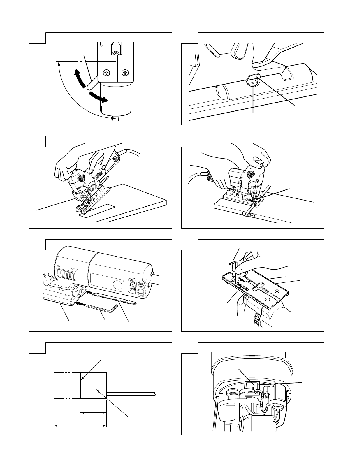
6. Angular cutting
To adjust the slant angle, loosen the base handle
located directly below the housing by rotating it
approximately 90 degrees and then move the groove
in the semi-circular part to the position indicated
by the mark on the gear cover.
Next, align the scale (from 0 degrees to 45 degrees
in 15-degree increments) of the semi-circular part
of the base with the [
] mark on the gear cover,
rotate the base handle approximately 90 degrees
counterclockwise, return to directly below the
housing and tighten (Figs. 8, 9, 10, 12).
CONCERNING CUTTING OF STAINLESS
STEEL PLATES
CAUTION
While sawing, the base must be firmly in contact with the
workpiece surface, and the blade must be held at a right
angle. If the base becomes separated from the material,
it could cause the blade to break.
When cutting stainless steel plates, adjust the unit as
described below:
1. Adjust the speed……
NOTE
Dial scale reading is for reference only. The higher
the speed is, the quicker the material is cut. But
the service life of the blade will be reduced in this
case. When the speed is too low, cutting will take
longer, although the service life will be prolonged.
Make adjustments as desired.
2. Set the orbital position to “0” ………
NOTE
䡬 When cutting use cutting fluid (oil base cutting
fluid) to prolong the blade’s service life.
SELECTION OF BLADES
䡬 Accessory blades
To ensure maximum operating efficiency and results,
it is very important to select the appropriate blade
best suited to the type and thickness of the material
to be cut. Three types of blades are provided as
standard accessories. The blade number is engraved
in the vicinity of the mounting portion of each
blade. Select appropriate blades by referring to
Table 1.
HOUSING THE SAW BLADES AND THE
HEXAGONAL BAR WRENCH
It is possible to house the auxiliary hexagonal bar wrench
and saw blades (2-3 blades) inside the base (see Fig. 13).
If saw blades get caught in the interior of the base, insert
the auxiliary wrench inside the groove on the back of the
base to remove the blades. (Fig. 14)
MAINTENANCE AND INSPECTION
1. Inspecting the blade
Continued use of a dull or damaged blade will
result in reduced cutting efficiency and may cause
overloading of the motor. Replace the blade with
a new one as soon as excessive abrasion is noted.
2. Inspecting the mounting screws:
Regularly inspect all mounting screws and ensure
that they are properly tightened. Should any of the
screws be loose, retighten them immediately. Failure
to do so could result in serious hazard.
3. Inspecting the carbon brushes (Fig. 15)
The motor employs carbon brushes which are
consumable parts. When they become worn to or
near the “wear limit”, it could result in motor trouble.
When an auto-stop carbon brush is equipped, the
motor will stop automatically.
At that time, replace both carbon brushes with new
ones which have the same carbon brush Numbers
Blade
Thickness of material
Dial Scale
No. 96 0.5 ~ 1.5 mm
No. 95 1.5 ~ 2.5 mm
No. 97 1.5 ~ 2.5 mm
Middle groove position
between scales “2”
and “3”
Page 9

7
English
shown in the figure. In addition, always keep carbon
brushes clean and ensure that they slide freely
within the brush holders.
4. Replacing carbon brushes (Fig. 16)
<Disassembly>
(1) Loosen the D4 tapping screw (1 screw) retaining
the tail cover and remove the tail cover.
(2) Use a small screw-driver to pull up the edge of
the coil spring that are holding down the carbon
brush. Remove toward the outside of the brush
holders.
(3) Remove the edge of the pig-tails on the carbon
brushes, from the wiring block group (A) and then
remove the carbon brushes from the brush holders.
<Assembly>
(1) Insert the end of the pig tails of the carbon brushes
in the terminal section of the wiring block (A).
(2) Insert the carbon brushes in the brush holders.
(3) Use the small screwdriver to return the edge of the
coil spring to the head of the carbon brushes.
(4) Check that the pig tails of the carbon brushes are
completely inserted in the pig tail’s groove on the
brush holders.
(5) Close the tail cover and tighten the D4 tapping
screw (1 screw).
5. Maintenance of the motor
The motor unit winding is the very “heart” of the
power tool.
Exercise due care to ensure the winding does not
become damaged and/or wet with oil or water.
NOTE
䡬 The minimum cutting radius of No. 1 (Long), No. 21, No. 22 and No. 41 blades is 100 mm.
䡬 No. 1 (Long), No. 11, No. 12, No. 15, No. 16, No. 21, No. 22, No. 95, No. 96 and No. 97 blades are sold
separately.
Table 1 List of appropriate blades
Material
Blade
No. 1
No.11
No. 12,
No. 15
No. 16, No. 21,
No. 22 No. 95 No. 96 No. 97
to be cut
(Long) 42 46 41
Material quality Thickness of material (mm)
Lumber
General lumber
Below 10 ∼ Below 10 ∼ 5 ∼
100 60 20 60 40
Plywood
5 ∼ Below 5 ∼ 3 ∼
30 10 30 20
Iron plate
Mild steel plate
3 ∼ Below 3 ∼ Below 2 ∼
10 3 6 3 5
Stainless steel plate
1.5 ∼ 0.5 ∼ 1.5 ∼
2.5 1.5 2.5
Nonferrous
Aluminium copper, brass
3 ∼ Below 3 ∼ Below Below
metal
12 3 12 3 5
Aluminium sash
Height Height Height
up to up to up to
30 30 30
Plastics
Phenol resin, melamin, 5 ∼ Below 5 ∼ Below 5 ∼ Below 5 ∼
resin, etc. 20 6 15 6 20 6 15
Vinyl chloride, 5 ∼ Below 5 ∼ Below 5 ∼ 3 ∼ 5 ∼ Below 5 ∼
acryl resin, etc. 30 10 20 5 30 20 20 5 15
Foamed polyethylene, 10 ∼ 3 ∼ 5 ∼ 3 ∼ 10 ∼ 3 ∼ 5 ∼ 3 ∼ 5 ∼
foamed styrol 60 30 30 30 60 40 30 30 30
Pulp
Card board, 10 ∼ 3 ∼ 10 ∼ 3 ∼
corrugated paper 60 30 60 40
Hardboard
3 ∼ Below 3 ∼ Below 3 ∼
30 6 30 6 30
Fiberboard
Below
6
Page 10

English
8
NOTE
Due to HITACHI’s continuing program of research and
development, the specifications herein are subject to
change without prior notice.
IMPORTANT
Correct connection of the plug
The wires of the main lead and coloured in accordance
with the following code:
Blue: -Neutral
Brown: -Live
As the colours of the wires in the main lead of this tool
may not correspond with the coloured markings
identifying the terminals in your plug proceed as follows:
The wire coloured blue must be connected to the terminal
marked with the letter N or coloured black.
The wire coloured brown must be connected to the
terminal marked with the letter L or coloured red.
Neither core must be connected to the earth terminal.
NOTE
This requirement is provided according to BRITISH
STANDARD 2769: 1984.
Therefore, the letter code and colour code may not be
applicable to other markets except The United Kingdom.
Information concerning airborne noise and vibration
The measured values were determined according to
EN50144.
The typical A-weighted sound pressure level: 87 dB (A).
The typical A-weighted sould power level: 100 dB (A).
Wear ear protection.
The typical weighted root mean square accelaration
value does not exceed 2.5m/s2.
Page 11

9
Deutsch
ALLGEMEINE VORSICHTSMASSNAHMEN
WARNUNG! Bei der Verwendung von Elektrowerkzeugen
müssen immer die grundlegenden Vorsichtsmaßnahmen
befolgt werden, um das Risiko von Feuer, elektrischem
Schlag und persönlicher Verletzung und den
nachfolgenden Punkten zu vermeiden.
Lesen Sie diese Anweisungen völlig, bevor Sie dieses
Erzeugnis verwenden, und bewahren Sie diese
Anweisungen auf.
Für sicheren Betrieb:
1. Der Arbeitsplatz sollte sauber gehalten werden.
Unaufgeräumte Arbeitsplätze und Werkbänke
erhöhen die Unfallgefahr.
2. Die Betriebsbedingungen beachten.
Elektrowerkzeuge sollten nicht dem Regen
ausgesetzt werden.
Ebenfalls sollten Sie nicht an feuchten oder nassen
Plätzen gebraucht werden.
Der Arbeitsplatz sollte gut beleuchtet sein.
Verwenden Sie Elektrowerkzeuge nicht an Orten,
an denen die Gefahr von Feuer oder Explosion
besteht.
3. Schutzmaß nahmen gegen elektrische Schläge
treffen. Darauf achten, daß das Gehäuse nicht in
Kontakt mit geerdeten Flachen kommt, z. (z.B.
Rohre, Radiatoren, Elektroherde, Kühlschränke).
4. Kinder sollten vom Gerät ferngehalten werden.
Vermeiden, daß andere Personen mit dem
Werkzeung oder Verlängerungskabel in Kontakt
kommen.
5. Nicht benutzte Werkzeuge sollten sicher aufbewahrt
werden. Sie sollten an einem trockenen und
verschließbaren Ort aufbewahrt werden, damit
Kinder sie nicht in die Hände bekommen.
6. Werkzeuge sollten nicht mit übermäßiger Gewalt
verwendet werden. Ihre Leistung ist besser und
sicherer, wenn sie mit der vorgeschriebenen
Geschwindigkeit verwendet werden.
7. Nur die korrekten Werkzeuge verwenden. Niemals
ein kleineres Werkzeug oder Zusatzgerat für
Arbeiten verwenden, die Hochleistungsgerate
erfordern. Nur Werkzeuge verwenden, die dem
Verwendungszweck entsprechen, d.h. niemals eine
Kreissäge zum Sägen von Ästen oder
Baumstämmen verwenden.
8. Die richtige Kleidung tragen. Keine lose Kleidung
oder Schmuck tragen, da sich lose Kleidungsstücke
in den bewegenden Teilen verfangen kònnen. Bei
Arbeiten im Freien sollten Gummihandschuhe und
rutschfeste Schuhe getragen werden.
9. Es sollte eine Sicherheitsbrille getragen werden.
Bei Arbeiten mit Staubentwicklung sollte eine
Gesichtsoder Staubmaske getragen werden.
10. Schließen Sie eine Staubabsaugvorrichtung an.
Wenn Vorrichtungen für den Anschluß von
Staubabsaug- und -sammelvorrichtungen
vorhanden sind, so stellen Sie sicher, daß diese
angeschlossen sind und richtig verwendet werden.
11. Niemals das Kabel mißbrauchen. Ein Werkzeug
niemals am Kabel tragen oder bei Abtrennung
von der Steckdose das Kabel harausreißen. Das
Kabel sollte gegen Hitze, Öl und scharfe Kanten
geschützt werden.
12. Den Arbeitsplatz gut absichern. Zwingen oder einen
Schraubstock zur Befestigung des Werkstücks
verwenden. Das ist sicherer als die Benutzung der
Hände und macht beide Hände zur Bedienung des
Werkzeugs frei.
13. Sich niemals weit überbeugen. Immer einen festen
Stand und ein sicheres Gleichgewicht bewahren.
14. Die Werkzeuge sollten sorgfältig behandelt werden.
Für einen einwandfreien und sicheren Betrieb
sollten sie stets scharf sein und saubergehalten
werden. Die Anleitungen für schmierung und
Austausch des Zuehörs unbedingt einhalten. Die
Kabel der Geräte regelmäßig überprüfen und bei
Beschädigung durch eine autorisierte
Kundendienststelle reparieren lassen.
Ebenfalls die Verlägerungskabel regelmäßig
überprüfen und bei Beschadigung auswechseln.
Die Handgriffe sollten stets trocken und sauber
sein, sowie keine Ol- oder Schmierfett stellen
aufweisen.
15. Werkzeuge vom Netz trennen, wenn sie nicht
benutzt werden, vor Wartungsarbeiten und beim
Austausch von Zubehörteilen wie z.B. Blätter,
Bohrer und Messer.
16. Alle Stellkeile und Schraubenschlüssel entfernen.
Vor Einschaltung des Gerätes darauf achten, daß
alle Stellkeile und Schraubenschlüssel entfernt
worden sind.
17. Ein unbeabsichtigtes Einschalten sollte vermieden
werden. Niemals ein angeschlossenes Werkzeug
mit dem Finger am Schalter tragen. Vor Anschluß
überprüfen, ob das Gerät ausgeschaltet ist.
18. Im Freien ein Verlängerungskabel verwenden. Nur
ein Verlängerungskabel verwenden, das für die
Verwendung im Freien markiert ist.
19. Den Arbeitsvorgang immer unter Kontrolle haben.
Das Gerät niemals in einem abgespannten Zustand
verwenden.
20. Beschädigte Teile überprüfen. Vor Benutzung des
Werkzeugs sollten beschädigte Teile oder
Schutzvorrichtungen sorgfältig überprüft werden,
um festzustellen, ob sie einwandfrei funktionieren
und die vorgesehene Funktion erfüllen,
Ausrichtung, Verbindungen sowie Anbringung sich
bewegender Teile überprüfen. Ebenfalls
uberprufen, ob Teile gebrochen sind. Teile oder
Schutzvorrichtungen, die beschädigt sind, sollten,
wenn in dieser Bedienungsanleitung nichts anderes
erwähnt ist, durch eine autorisierte
Kundendienststelle ausge wechselt oder repariert
werden. Dasselbe gilt für defekte Schalter.
Wenn sich das Werkzeug nicht mit dem Schalter
einoder ausschalten läßt, sollte das Werkzeug nicht
verwendet werden.
21. Warnung
Die Verwendung von anderem Zubehör oder
anderen Zusätzen als in dieser Bedienungsanleitung empfohlen kann das Risiko einer
Körperverletzung einschließen.
22. Lassen Sie Ihr Werkzeug durch qualifiziertes
Personal reparieren. Dieses Elektrowerkzeug
entspricht den zutreffenden Sicherheitsanforderungen. Reparaturen sollten nur von
qualifiziertem Personal unter Verwendung von
Originalersatzteilen durchgeführt werden, da sonst
beträchtliche Gefahr für den Benutzer auftreten
kann.
Page 12

10
Deutsch
STANDARDZUBEHÖR
(1) Sägeblätter (Nr. 41, 42, 46) ................................... 1
Für Anwendung der Sägeblätter siehe Tabelle 1.
(2) Innenscechskantchiüssel .......................................... 1
(3) Splitterschutz ............................................................. 1
Das Standardzubehör kann ohne vorherige Bekanntmachung jederzeit geändert werden.
SONDERZUBEHÖR ... separat zu beziehen
(1) Verschiedene Sägeblatt-Typen
Für Anwendung der Sägeblätter siehe Tabelle 1.
(2) Staubsauger
(3) Parallelschneider
(4) Kreisschneider
(5) Bankstütze (Modell TR12-B)
Das Sonderzubehör kann ohne vorherige
Bekanntmachung jederzeit geändert werden.
ANWENDUNGEN
䡬 Schneiden verschiedener Nutzhölzer (auch
Aussparungen)
䡬 Schneiden von Flußstahlblechen, Aluminiumblechen
und Kupferblechen.
䡬 Schneiden von Kunstharzen wie Phenolharz und
Vinylchlorid
䡬 Schneiden von dünnen und weichen Baumaterialien
䡬 Schneiden von Blechen aus rostfreiem Stahl (mit
Sägeblatt Nr. 95, Nr. 96 oder Nr. 97)
VOR DER INBETRIEBNAHME
1. Netzspannung
Prüfen, daß die zu verwendende Netzspannung der
Angabe auf dem Typenschild entspricht.
2. Netzschalter
Prüfen, daß der Netzschalter auf ,,AUS“ steht. Wenn
der Stecker an das Netz angeschlossen wird,
während der Schalter auf ,,EIN“ steht, beginnt das
Werkzeug sofort zu laufen, was gefährlich ist.
3. Verlängerungskabel
Wenn der Arbeitsbereich nicht in der Nähe des
Netzanschlusses liegt, ist ein Verlängerungskabel
ausreichenden Querschnitts und ausreichender
Nennleistung zu verwenden. Das Verlängerungskabel
sollte so kurz wie möglich gehalten werden.
4. Anbringen des Sägeblattes
(1) Die Spitzenabdeckung öffnen (Abb. 1).
(2) Mit dem Innensechskantschüssel werden die
Klemmschrauben des Sägeblattes am Einstellring
gelockert, wie in Abb. 2 dargestellt.
(3) Das Anbaustück des Blattes vollkommen in den
Einstellring mit der Hinterseite des Blates in Schlitz
eingreifend einsetzen und die Klemmschraube
anziehen (Abb. 2).
(4) Den Schnipseldeckel schließen (Abb. 1).
HINWEISE:
Lose Klemmschrauben können zur Beschädigung
des Sägeblattes führen. Es ist immer derauf zu
achten, daß der Anbauteil des Einstellrings sauber
und ohne Sägemehl ist, um zweckmäßiges
Anbringen des Sägeblattes und richtiges Klemmen
der Klemmschrauben zu gewährleisten.
5. Einstellen der Arbeitsgeschwindigkeit des Sägeblattes
Die CJ110VA ist mist einem kontrollstromkreis
ausgestattet der stufenlose Geschwindigkeitskontrolle
ermöglicht. Um die Geschwindigkeit einzustellen,
die Skalenscheibe die auf Abb. 3 gezeigt ist drehen.
Wenn die Scheibe auf ,,1“ eingestellt ist, arbeitet
die Stichsäge auf Mindestgeschwindigkeit (700/min).
Wenn auf ,,5“ eingestellt, arbeitet die Stichsäge auf
VORSICHTSMASSNAHMEN BEI DER
BEDIENUNG DER STICHSÄGE
Diese Machine arbeitet mit einem starken Motor. Wenn
die Maschine längere Zeit b ei niedriger Geschwindigkeit
verwendet wird, wird der Motor stark belastet und kann
sich festfressen. Das Werkzeug immer so einsetzen, daß
das Sägeblatt beim Betrieb nicht im Werkstück festsitzt.
Immer die Geschwindigkeit so einstellen, daß gut gesägt
werden kann.
TECHNISCHE DATEN
Spannung (ja nach Gebiert)* (110V, 115V, 120V, 127V, 220V, 230V, 240V)
Leistungsaufnahme* 570W
Max. Schneidtiefe
Holz 100 mm
Flußstahl 10 mm
Leerlaufhubzahlen 700 – 3200 Hübe/min
Hubstrecke 26 mm
Mindestschnittradius 25 mm
Gewicht (ohne Kabel) 2,4 kg
*Vergessen Sie nicht, die Produktangaben auf dem Typenschild zu überprüfen, da sich diese je nach Verkaufsgebiet
ändern.
Page 13

11
Deutsch
Hochstgeschwindigkeit (3200/min). Die
Geschwindigkeit je nach Schnittmaterial und
Arbeitsleistung einstellen.
ACHTUNG
Bei kleiner Geschwindigkeit (Skalaeinstellung: 1 oder
2), kein Holzstück von einer Dicke über 10 mm oder
Stahl von einer Dicke über 1 mm schneiden.
6. Einstellen des Umlaufbetriebs
(1) Diese Maschine funktioniert mit Umlaufbetrieb der
das Sägeblatt von vorn nach hinten, und auch von
oben nach unten bewegt.
Den Wechselknopf der auf Abb. 4 gezeigt ist auf
,,0“ einstellen um den Umlaufbetrieb auf das
Mindestmaß herabzusetzen (das Sägeblatt bewegt
sich nur von oben nach unten). Der Umlaufbetrieb
kann in 4 Stufen von ,,0“ bis ,,III“ gewählt werden.
(2) Für hartes Material, wie Stahlblech, usw., den
Umlaufbetrieb herabsetzen. Für weiches Material,
wie Bauholz, Kunstoff, usw, den Umlaufbetrieb, um
die Arbeitsleistung zu erhöhen, steigern. Um Material
mit Genauigkeit zu schneiden den Umlaufbetrieb
herabsetzen.
7. Sägen von rostfreien Stahlblechen
Mit dem Modell CJ110VA und Sägeblatt Nr. 95, Nr.
96 und Nr. 97 ist Schneiden von Stahlblechen
möglich. Für korrekte Bedienung bitte den Abschnitt
,,Betreffend Sägen von rostfreien Stahlblechen“
aufmerksam durchlisen.
8. Splitterschutz
Die Verwendung des Splitterschutzes beim
Schneiden von Holzmaterialen reduziert das Splittern
an der Oberfläche. Den Splitterschutz in den Spalt
zwischen dem Unterbau und dem Nebenunterbau
einsetzen, nach vorn schieben und befestigen (siehe
Abb. 5).
SCHNEIDEN
ACHTUNG
䡬 Beim Sägen muß der Sägetisch fest auf der
Oberfläche des Werkstücks auf liegen und das
Sägeblatt im rechten Winkel gehalten werden. Wenn
der Sägetisch das Material nicht berührt, kann das
zum zerbrechen das Sägeblatts führn.
1. Parallelschneiden
Zum Schneiden in gerader Richtung zuerst eine
Markierungslinie aufzeichnen und dann an dieser
Linie entlangsägen. Die als sonderzubehör erhältliche
Führung sorgt hierbei für Richtungsstabilität und
ermöglicht akkurates Sägen in Geradeausrichtung.
Hierzu die Sägeführung durch das Befestigungsloch
am Unterbau stecken und die M5-Knopfschraube
festziehen. (Abb. 6)
2. Sägen von krummen Linien
Beim Sägen eines kleinen Kreisbogens wird die
Schiebgeschwindigkeit der Maschine verringert.
Wenn die Maschine zu schnell geschoben wird,
könnte das zum zerbrechen des Sägeblatts führen.
3. Schneiden eines Kreises oder eines Bogens
Für kreis- oder bogenförmige Sägeschnitte ist die
Kreisschnittführung und die Mittenführung
(Sonderzubehör) äußerst nützlich (Abb. 7).
Den Basishandgriff, der sich direkt unterhalb des
Gehäuses befindet, durch Drehung um etwa 90
Grad lösen. Dann die Basis völlig nach vorn
bewegen, den Basishandgriff um etwa 90 Grad
gegen den Uhrzeigersinn drehen, die Basis direkt
unter das Gehäuse zurückbringen und anziehen
(Abb. 8, 9).
Die Kreisschnittführung durch das Befestigungsloch
stecken und die M5-Knopfschraube festziehen.
4. Schneiden von Metallen
Immer ein geeignetes Schneidemittel verwenden
(Spindelöl, Seifenwasser, usw.). Wenn ein flüssiges
Schneidemittel nicht zur Verfügung steht, wird auf
die Rückseite des zu schneidenden Materials Fett
aufgetragen.
5. Schneiden von Löchern
(1) In Schnittholz
Die Schnittrichtung wird der Faserrichtung des
Holzes angepasst. Es wird Schritt für Schritt
geschnitten, bis ein Fenster in der Mitte des
Schnittholzes entstanden ist. (Abb. 11)
(2) In anderen Materialien
Beim Schneiden eines Fensters in anderen
Materialien als Holz wird zu Anfang ein Loch mit
einer Bohrmaschine oder einem ähnlichen Werkzeug
gebohrt, von dem aus das Schneiden beginnt.
6. Schrägschnitte
Zum Einstellen des Neigungswinkels den
Basishandgriff, der sich direkt unterhalb des
Gehäuses befindet, durch Drehung um etwa 90
Grad lösen, und dann die Nut im halbkreisförmigen
Teil zu der durch die Markierung an der
Getriebeabdeckung angezeigten Position bringen.
Dann die Skala (von 0 Grad bis 45 Grad in Schritten
von 15 Grad) des halbkreisförmigen Teils der Basis
auf die Markierung [
] an der Getriebeabdeckung
ausrichten, den Basishandgriff um etwa 90 Grad
gegen den Uhrzeigersinn drehen, direkt unter das
Gehäuse zurückbringen und anziehen (Abb. 8, 9, 10,
12).
BETREFFEND SÄGEN VON ROSTFREIN
STAHLBLECHEN
ACHTUNG
Beim Sägen muß der Sägetisch fest auf der Oberfläche
des Werkstückes liegen und das Sägeblatt im rechten
Winkel gehalten werden. Wenn der Sägetisch das Material
nicht berührt, kann das zu einem Bruch des Sägeblattes
führen.
Beim sägen von rostfreien Stahlblechen die Einheit wie
unten angegeben einstellen:
1. Geschwindigkeitseinstellung……
VORSICHT
Die Drehreglerskalen-Anzeige dient nur als
Bezugswert. Je höher die Geschwindigkeit ist,
destoschneller wird das Material gesägt. Die
Lebensdauer des Sägeblattes aber wird in diesem
Fall verringert. Wenn die Geschwindigkeit zu giedrig
ist, nimmt das Sägen längere Zeit in Anspruch, aber
die Lebnsdauer wird verlängert. Die Einstellung nach
Wunsch vornehmen.
Sägeblatt
Dicke des Materials Drehscheibenskala
Nr. 96 0,5 bis 1,5 mm
Nr. 95 1,5 bis 2,5 mm
Nr. 97 1,5 bis 2,5 mm
Mittelrillenstellung
zwischen den Werten ,,2“
und ,,3“ auf der Skala
Page 14

12
Deutsch
2. Die Orbitalstellung ,,0“ wählen ……
VORSICHT
䡬 Beim Sägen immer Sägeflüssigkeit verwenden
(Ölschneideflüssigkeit), um die Lebnsdauer des
Sägeblattes zu verlängern.
AUSWAHL DER SÄGEBLÄTTER
䡬 Standardzubehör
Für maximale Leistung ist es sehr wichtig, das
Sägeblatt auszuwählen, das sich bei den
Eigenschaften des zu schneidenden Materials am
besten eignet. Als Standardzubehör werden drei
Sägeblattypen geliefert. Die Nummer des Sägeblatts
ist in der Nähe der Halterung jedes Sägeblatts
eingraviert. Das geeignete Sägeblatt wird anhand
der Tabelle 1 bestimmt.
AUFBEWAHRUNG VON SÄGEBLATT UND
SECHSKANTSCHLÜSSEL
Sechskantschlüssel und Sägeblätter (2-3 Sägeblätter)
können im Unterbau (siehe Abb. 13) verstaut werden.
Falls sich sägeblätter im Unterbau verklemmen, den
mitgelieferen Sechskantschlüssel in den spalt an der
Rückseite des Unterbaus stecken und die Sägeblätter auf
diese Weise lösen. (Abb. 14)
WARTUNG UND INSPEKTION
1. Inspektion des Sägeblatts
Die Weiterverwendung eines stumpfen oder
beschädigten Sägeblatts führt zu verminderter Schnit
tleistung und kann eine Überbelastung des Motors
hervorrufen. Das Sägeblatt wird durch ein neues
ersetzt, wenn übermäßige Abnutzung festgestellt
wird.
2. Inspektion der Befestigungsschrauben:
Alle Befestigungsschrauben werden regelmäßig
inspiziert und geprüft, ob sie gut angezogen sind.
Wenn sich eine der Schrauben lockert, muß sie
sofort wieder angezogen werden. Geschieht das
nicht, kann das zu erheblichen Gefahren führen.
3. Inspektion der Kohlebürsten (Abb. 15)
Im Motor sind Kohlebürsten verwendet, die
Verbrauchsteile sind. Wenn sie abgenützt sind, kann
es zu Motorschäden führen. Wenn der Motor mit
einer Auto-Stop Kohlebürste ausgestattet ist, wird
er automatisch anhalten. Beide Kohlebürsten sollen
dann durch neue ersetzt werden, die dieselbe
Bürstennummer tragen wie auf der Abbildung.
Darüber hinaus müssen die Kohlebürsten immer
sauber gehalten werden und müssen sich in der
Bürstenhalterung frei bewegen können.
4. Austausch einer Kohlebürste: (Abb. 16)
<Zerlegen>
(1) Die D4-Schneidschraube (1 Schraube) an der hinteren
Abdeckung herausschrauben und die hintere
Abdeckung entfernen.
(2) Das Ende der Spiralfeder, welche die Kohlebürste
nach unten drückt, mit dem kleinen Schraubenzieher
nach oben ziehen und sie aus den Bürstenhaltern
entfernen.
(3) Die kante der Anschlußlitze an der kohlebürste von
der Verdrahtungsblock-Baugruppue (A) entfernen
und die kohlebürste aus dem Bürstenhalter nehmen.
<Baugruppe>
(1) Das Ende der kohlenbürsten-Anschlußlitze in den
Anschlußteil des Verdrahtungsblocks (A) einstekken.
(2) Die kohlebürste in den Bürstenhalter einsetzen.
(3) Das Ende der Spiralfeder mit dem kleinen
Schraubenzieher auf das Oberteil der Kohlebürsten
zurückbringen.
(4) Vergewissern, daß die Anschlußlitze der kohlebürste
ganz in die Anschlußlitzenkerbe am kohlebür-
stenhalter eingesteckt ist.
(5) Die hintere Abdeckung wieder ansetzen und mit der
D4-Schneidschraube (1 Schraube) anmontieren.
5. Wartung des Motors
Die Motorwicklung ist das ,,Herz“ des Elektro-
werkzeugs. Daher ist besonders sorgfältig darauf zu
achten, daß die Wicklung nicht beschädigt wird
und/oder mit Öl oder Wasser in Berührung kommt.
ANMERKUNG
Aufgrund des ständigen Forschungs-und Entwicklungsprogramms von HITACHI sind Änderungen der hierin
gemachten technischen Angaben nicht ausgeschlossen.
Page 15

13
Deutsch
VORSICHT
䡬 Der Mindest-Schnittradius von Sägeblatt Nr. 1 (Lang), Nr. 21, Nr. 22 und Nr. 41 ist 100 mm.
䡬 Sägeblätter Nr. 1 (Lang), Nr. 11, Nr. 12, Nr. 15, Nr. 16, Nr. 21, Nr. 22, Nr. 95, Nr. 96 und Nr. 97 sind getrennt
kaufbar.
Information über Betriebslärm und Vibration
Die Meßwerte wurden entsprechend EN50144 bestimmt.
Der typische A-gewichtete Schalldruckt ist 87 dB (A).
Der typische A-gewichtete Schalleistungspegel ist 100 dB
(A).
Bei der Arbeit immer einen Ohrenschutz tragen.
Der typische gewichtete Effektiv-Beschleunigungswert
überschreitet nicht 2,5m/s2.
Tabelle 1 Liste der geeigneten Sägeblätter
Zu schneiden-
Sägeblätter
Nr. 1
Nr.11
Nr. 12,
Nr. 15
Nr. 16, Nr. 21,
Nr. 22 Nr. 95 Nr. 96 Nr. 97
des Material
(Lang) 42 46 41
Materialqualität Dicke des Materials (mm)
Schnittholz
Allgemeines Schnittholz
Unter 10 ∼ Unter 10 ∼ 5 ∼
100 60 20 60 40
Furnierplaten
5 ∼ Unter 5 ∼ 3 ∼
30 10 30 20
Einsenblech
Flßstahlblech
3 ∼ Unter 3 ∼ Unter 2 ∼
10 3 6 3 5
Rostfreies Stahlblech
1,5 ∼ 0,5 ∼ 1,5 ∼
2,5 1,5 2,5
Nichteisen-
Aluminium, Kupfer, 3 ∼ Unter 3 ∼ Unter Unter
metalle
Messing 12 3 12 3 5
Hohe Hohe Hohe
Aluminiumschürze bis zu bis zu bis zu
30 30 30
Kunststoffe
Phenolharz, 5 ∼ Unter 5 ∼ Unter 5 ∼ Unter 5 ∼
Melaminharz, usw. 20 6 15 6 20 6 15
Vinylchlorid, 5 ∼ Unter 5 ∼ Unter 5 ∼ 3 ∼ 5 ∼ Unter 5 ∼
Acrylharz, usw. 30 10 20 5 30 20 20 5 15
Geschäumtes Polyäthylen, 10 ∼ 3 ∼ 5 ∼ 3 ∼ 10 ∼ 3 ∼ 5 ∼ 3 ∼ 5 ∼
Geschäumtes Styrol 60 30 30 30 60 40 30 30 30
Holzfaser-
Pappe, Wellpappe
10 ∼ 3 ∼ 10 ∼ 3 ∼
material
60 30 60 40
Hartfaserplatte
3 ∼ Unter 3 ∼ Unter 3 ∼
30 6 30 6 30
Faserplatte
Unter
6
Page 16

14
Français
PRECAUTIONS GENERALES DE TRAVAIL
ATTENTION! Lors de l’utilisation d’un outillage
électrique, les précautions de base doivent être
respectées de manière à réduire les risques d’incendie,
de secousse électrique et de blessure corporelle, y
compris les précautions suivantes.
Lire ces instructions avant d’utiliser le produit et
conserver ces instructions pour référence.
Pour assurer un fonctionnement sûr:
1. Maintenir l’aire de travail propre. Des ateliers ou
des établis en désordre risquent de provoquer des
accidents.
2. Tenir compte de l’environnement de l’aire de tra
vail. Ne pas exposer les outils électriques à la
pluie.
Ne pas les utiliser dans des endroits humides.
Travailler dans un endroit bien éclairé.
Ne pas utiliser d’outillage électrique s’il existe un
risque d’incendie ou d’explosion.
3. Protection contre une décharge électrique. Eviter
tout contact corporel avec des surfaces de mise
à la terre telles que les tuyaux, radiateurs,
cuisinières et réfrigérateurs.
4. Tenir les enfants éloignés. Ne pas laisser les
visiteurs toucher l’outil ou son cordon
d’alimentation. Il est préférable de tenir les visiteurs
à l’écart de l’aire de travail.
5. Ranger les outils non utilisés. Quand on ne les
utilise pas, il est recommandé de ranger les outils
dans un endroit sec, verrouillé ou hors de portée
des enfants.
6. Ne pas forcer l’outil. Il fonctionnera mieux et plus
sûrement à la vitesse pour laquelle il a été con
cu.
7. Utiliser l’outil approprié. Ne pas essayer de faire
avec un petit outil le travail prevu pour un outil
plus important. Toujours utiliser l’outil adéquat;
par exemple, ne pas se servir d’une scie circulaire
pour couper des branches d’arbres ou des billots
de bois.
8. Porter des vêtements appropriés. Ne pas mettre
de vêtements flottants ou de bijoux qui risquent
d’être pris dans les pièces mobiles. Si l’on travaille
à l’extérieur, il est recommandé de porter des
gants de caoutchouc et des chaussures à semelles
antidérapantes. Veiller à s’attacher les cheveux ou
à mettre un bonnet si on a les cheveux longs.
9. Porter des lunettes protectrices. Mettre un masque
si l’opération de coupe crée de la poussière.
10. Relier l’équipement d’extraction de poussière.
Si des dispositifs sont prévus pour le raccordement
d’installations d’extraction et de collection de
poussière, s’assurer qu’ils sont correctement
raccordés et utilisés.
11. Prendre soin du fil. Ne jamais transporter l’outil
en le tenant par le fil et ne pas le débrancher en
tirant sur le fil d’un coup sec. Tenir le fil à l’abri
de la chaleur, l’éloigner de l’huile ou de bords
tranchants.
12. Fixer fermement la piêce à travailler. Utiliser des
agrafes ou un étau pour la maintenir, C’est plus
sûr que d’utiliser ses mains et cela les libêre pour
faire fonctionner l’outil.
13. Ne pas présumer de ses forces. Essayer de garder
son équilibre en toute circonstance.
14. Entretenir les outils avec soin. Les conserver bien
aiguisés et les nettoyer afin d’en obtenir les
meilleures performances et de pouvoir les utiliser
sans danger. Suivre les instructions pour le
graissage et le changement des accessoires.
Vérifier régulièrement les fils et cordons et s’ils
sont endommagés, les faire réparer par une
personne compétente. Vérifier régulièrement les
rallonges et les remplacer si elles sont
endommagées. Veiller à ce que les poignées soient
toujours sèches et propres, sans huile ni graisse.
15. Debrancher les outils lorsqu’on ne les utilise pas,
avant toute opération d’entretien et lors du
changement d’accessoire; comme par exemple
quand on change les lames, les forets, le fraises,
etc.
16. Retirer les clés de réglage. Prendre l’habitude de
toujours vérifier que les clés de réglage sont bien
retirées de l’appareil avant de le mettre en marche.
17. Eviter toute mise en marche accidentelle. Ne pas
transporter l’outil branché avec un doigt sur
l’interrupteur. S’assurer que l’interrupteur est sur
la position d’arrêt quand on branche l’outil.
18. Utilisation de rallonges à l’extérieur. Quand on
utilise l’outil à l’extérieur, ne se servir que des
rallonges prévues pour l’extérieur et portant une
marque distinctive.
19. Soyez vigilant. Regardez bien ce que vous faites.
Faites appel à votre bon sens. N’utilisez pas l’outil
quand vous êtes fatigué.
20. Vérifier les pièces endommagées. Avant d’utiliser
davantage l’outil, vérifier attentivement toute pièce
endommagée afin de déterminer si l’outil peut
fonctionner correctement et effectuer le travail
pour lequel il est prévu. Vérifier l’alignement et
la flexion des piêces mobiles, la cassure des pièces,
le montage et toute autre condition risquant
d’affecter le bon fonctionnement de l’outil. Un
protecteur ou toute autre pièce endommagée devra
être correctement réparé ou remplacé par un
service d’entretien autorisé, sauf autre indication
dans ce mode d’emploi. Faire remplacer les
interrupteurs défectueux par un service d’entretien
autorisé. Ne pas utiliser l’outil si l’interrupteur ne
permet pas de le mettre en marche ou de l’arrêter.
21. Précaution
L’utilisation d’un accessoire ou dispositif annexe
autre que ceux conseillés dans ce mode d’emploi
peut entraîner un risque de blessure corporelle.
22. Confier la réparation d’un outil à un technicien
qualifié. Cet outil électrique a été conçu
conformément aux règles de sécurité en usage.
Les réparations doivent être effectuées par du
personnel qualifié utilisant des pièces d’origine.
Dans le cas contraire, l’utilisateur s’expose à des
risques graves.
Page 17

Français
15
PRECAUTIONS POUR L’UTILISATION DE LA
SCIE A CHANTOURNER
Cette machine utilise un moteur à puissance élevée. Si la
machine est utilisée continuellement à faible vitesse, une
charge supplémentaire est appliquée au moteur et peut
en provoquer son mauvais fonctionnement. Toujours
utiliser la scie de façon à ne pas coincer la lame dans la
pièce lors de son usage. Toujours régler la vitesse de la
lame pour permettre une coupe en douceur.
ACCESSOIRES STANDARDS
(1) Lames (No. 41, No. 42, No. 46) .... 1 de chaque
Se référer au tableau 1 pour l’utilisation des lames.
(2) Clef à barre hexagonale ......................................... 1
(3) Anti-éclats .................................................................. 1
Les accessoires standards sont sujets à changement sans
préavis.
ACCESSOIRES A OPTION
... vendus séparément
(1) Les différents types de lame
Se référer au Tableau 1 pour l’utilisation des lames.
(2) Collecteur à poussiìre
(3) Pièce de guidage rectilinèaire
(4) Pièce de guidage circulaire
(5) Etabli (Modèle TR12-B)
Les accessoires à option sont sujets à changement sans
préavis.
APPLICATIONS
䡬 Coupe de différentes sortes de bois de charpente
et découpe d’ouvertures
䡬 Coupe de plaques en acier doux, plaques en
aluminium et en cuivre.
䡬 Coupe de résines synthétiques comme résine
phénolique et chlorure de vinyl
䡬 Coupe de matériaux de construction peu épais et
tendres.
䡬 Coupe de plaque dácier inoxydable. (avec les lames
No. 95, No. 96 ou No. 97).
AVANT LA MISE EN MARCHE
1. Source de puissance
S’assurer que la source de puissance à utiliser
correspond à la puissance indiquée sur la plaque
signalétique du produit.
2. Interrupteur de puissance
S’assurer que l’interrupteur de puissance est en
position ARRET. Si la fiche est branchée alors que
l’interrupteur est sur MARCHE, l’outil démarre
immédiatement et peut provoquer un grave accident.
3. Fil de rallonge
Lorsque la zone de travail est éloignée de la source
de puissance, utiliser un fil de rallonge d’une
épaisseur suffisante et d’une capacité nominale
suffisante. Le fil de rallonge doit être aussi court
que possible.
4. Montage de la lame
(1) Ouvrir le couverche d’éclats (Fig. 1).
(2) Utiliser la clef à six pans pout desserrer la vis de
fixation de la lame sur la bague de fixation, comme
montré à la Fig. 2.
(3) Insérer à fond la partir de montage de la lame dans
la bague de fixation avec la face arrière de la lame
engagée avec la rainure et serrer la vis de fixation
(Fig. 2).
(4) Refermer le couverche d’éclats (Fig. 1).
REMARQUE:
Des vis de fixation desserrées peuvent provoquer
une détérioration de la lame. S'assurer toujours que
la vis de fixation est correctement serrée. S'assurer
toujours que la portion de monage de la bague de
fixation est propre et exempte de sciure pour
pourvoir effectuer un montage apropié de la lame
et un bon serrage de la vis de fixation.
5. Réglage de la vitesse de fonctionnement de la lame
La CJ110VA est équipée d’un circuit de contrôle
électrique qui permet un contrôle de vitesse
progressif.
Pour régler la vitesse, tourner le cadran montré à
la Fig. 3. Quand la cardran est réglé sur “1”, la scie
sauteuse fonctionne à la vitesse minimale (700/
min).
Tension (par zone)* (110V, 115V, 120V, 127V, 220V, 230V, 240V)
Puissance* 570W
Profondeur max. de coupe
Bois 100 mm
Acier doux 10 mm
Vitesse sans charge 700–3200/min
Course 26 mm
Rayon min. de coupe 25 mm
Poids (sans fil) 2,4 kg
*Assurez-vous de vérifier la plaque signalétique sur le produit qui peut changer suivant les régions.
SPECIFICATIONS
Page 18

16
Français
Quaned le cadran est réglé sur “5” la sauteuse
fonctionne à la vitesse maximale (3200/min).
Régler la vitesse suivant le matériel devant être
coupé et le rendment de travail.
ATTENTION
A petite vittesse (réglage de l’échelle sur: 1 ou 2),
ne pas couper une pièce de bois ayant plus de 10
mm d’épaisseur ou une pièce d’acier ayant plus de
1 mm d’épaisseur.
6. Réglage du fonctionnement orbital
(1) Cette machine utlise un fonctionnement orbital qui
déplace la lame tout aussi bien d’avant en arrière
que de haut en bas. Régler le bouton de changement
montré à la Fig. 4 sur “0” pour minimiser le
fonctionnement orbital (la lame ne se déplace que
de haut en bas). Le fonctionnement orbital peut être
sélectionné en quatres étapes de “0” à “III”.
(2) Pour les matériaux durs, tels que plaques d’acier,
etc., réduire le fonctionnement orbital. Pour les
matériaux moux, tels que bois de charpente,
matières plastiques, etc., augmenter le
fonctionnement orbital pour acroître le rendement
du travail. Pour couper les matériaux avec précision,
réduire le fonctionnement orbital.
7. Découpage de plaques en acier inoxydable
Le modèle CJ110VA, lorsqu’il est utilisé avec une
lame N° 95, 96 ou 97, peut couper des paques
d’acier inoxydable. Lire avec attention la partie
intitulée “Au sujet du découpage de plaques en
acier imoxydable” pour un fonctionnement correct.
8. Anti-éclats
L’utilisation de l’anti-éclats pendant la découpe de
matériaux en bois réduit considérablement les éclats
de copeaux.
Insérer l’anti-éclats dans l’espace compris entre la
base et la sous-base, le pousser vers l’avant et le
fixer. (Voir Fig. 5)
COUPE
PRECAUTIONS
䡬 Pendant l’opération de sciage, la base doit être
fermement en contact avec la surface de la pièce
travaillée et la lame doit être tenue à angle droit.
Si la base se trouve séparée du matériau, ceci
provoquera la rupture de la lame.
1. Coupe rectilinéaire
Pour découper en ligne droite, dessiner d’abord une
ligne de repère et avancer la scie le long de celleci. L’utilisation du guide auxiliaire de cécoupe en
ligne droite (vendu séparément) permet de couper
très précisément en ligne droite. Pour fixer le guide,
le faire passer par l’orifice de fixation et la serrer
avec la vis bouton M5. (Fig. 6)
2. Sciage de lignes courbes
Pour scier un peit arc circulaire, réduire la vitesse
d’alimentation de la machine. Une vitesse trop rapide
pourrait provoquer la rupture de la lame.
3. Coupe d’un cercle ou d’un arc circulaire
Dans se cas, le guide auxiliaire de découpe en
cercle et le centre de guide (vendu séparément)
sont très utiles (Fig. 7).
Desserrer la poignée du socle qui se trouve
directement sous le boîtier en la tournant d’environ
90 degrés. Puis, déplacer le socle à fond vers l’arrière,
tourner la poignée du socle d’environ 90 degrés
vers la gauche, ramener le socle directement endessous du boîtier et serrer (Fig. 8, 9).
Faire passer le guide de cercle par l’orifice de fixation
sur la base et serrer la vis bouton M5.
4. Coupe de matériaux métalliques:
Utiliser toujours un agent de coupe qui convient
(huile pour arbre, eau savonneuse etc.). Si un agent
de coupe liquide n’est pas disponible, appliquer de
la graisse au dos de la surface du matériau à
couper.
5. Découpe d’ouvertures
(1) Dans du bois de charpente:
En alignant la direction de la lame sur le grain du
bois, couper morceau par morceau jusqu’à ce qu’une
ouverture soit coupée au centre du bois. (Fig. 11)
(2) Dans d’autres matériaux:
Pour couper une ouverture dans des matériaux
autres que le bois de charpente, percer d’abord un
trou avec une perceuse ou un outil similaire à partir
duquel commencera la coupe.
6. Coupe angulaire
Pour régler l’angle d’inclinaison, desserrer la poignée
du socle qui se trouve directement sous le boîtier
en la tournant d’environ 90 degrés, puis déplacer
l’encoche de la section semi-circulaire sur la position
indiquée par le repère du couvercle de réducteur.
Ensuite, aligner l’échelle (de 0 degrés à 45 degrés
par paliers de 15 degrés) de la section semi-circulaire
du socle sur le repère [
] du couvercle de réducteur,
tourner la poignée du socle d’environ 90 degrés
vers la gauche, la ramener directement sous le
boîtier et serrer (Fig. 8, 9, 10, 12).
AU SUJET DU DECOUPAGE DE PLAQUES
EN ACIER INOXYDABLE
ATTENTION
Pendant l’opération de sciage, la base doit être
fermement en contact avec la surface de la pièce
travaillée, et la lame doit être tenue à angle droit. Si la
base se trouve séparée du matériau, ceci peut porvoquer
la rupture de la lame.
En coupant des plaques en acier inoxidable, régler
l’appareil de la façon suivante.
1. Pour régler la vitesse……
REMARQUE
L’échelle du cadran gradué n’est qu’une référence.
Plus la vitesse est élevée, le plus rapidement sera
coupé le matériau, mais la durée de vie de la lame
sera réduite dans ce cas là. Lorsque la vitesse est
réduite, la coupe prendra plus de temps, mais la
durée de vie sera prolongée. Faire les ajustements
selon préférence.
2. Régler la position orbitale sur “0” ……
REMARQUE
䡬 En coupant, faire usage de fluide de coupe (fluide
de coupe à base d’huile) pour prolonger la durée
de vie de la lame.
Lame
Epaisseur du matériau Echelle du cadran gradué
No. 96 0,5 – 1,5 mm
No. 95 1,5 – 2,5 mm
No. 97 1,5 – 2,5 mm
A positionner sur le sillon
à mi-chemin entre les
graduations “2” et “3”
Page 19

Français
17
CHOIX DES LAMES
䡬 Lames accessoires
Pour obtenir un fonctionnement optimal et les
meillleurs résultats possibles, il est très important
de choisir la lame la mieux appropriée au type et
à l’épaisseur du matériau à couper. Trois modèles
de lame sont fournies comme accessoires standards.
Le numéro de lame est gravé près de la section
de montage de chaque lame.
Choisir les lames appropriées en se référant au
Tableau 1.
RANGEMENT DES LAMES DE LA SCIE ET
DE LA CLÉ À SIX PANS
Il est possible de ranger la clé auxiliaire à six pans et les
lames (2-3 lames) dans la base (voir Fig. 13). Si les lames
sont coincées à l'intérieur de la base, insérer la clé
auxilaire dans la rainure au dos de la base pour les
enlever. (Fig. 14)
ENTRETIEN ET CONTROLE
1. Contrôle de la lame:
L’utilisation continue d’une lame émoussée ou
abîmée peut conduire à une réduction de effecacité
de coupe et provoquer une surcharge du moteur.
Remplacer la lame par une nouvelle dès que des
traces d’abrasion apparaissent.
2. Contrôle des vis de montage:
Vérifier régulièrement les vis de montage et s’assurer
qu’elles sont correctement serrées. Resserrer
immédiatement toute vis desserrée. Sinon, il y a
danger sérieux.
3. Contrôle des balais en carbone (Fig. 15)
Le moteur utilise des balais en carbone qui sont
des pièces qui s’usent. Quand ils sont usés ou près
de la “limite d’usure”, il pourra en résulter un
mauvais fonctionnement du moteur.
Quand le moteur est équipé d’un balai en carbone
à arrêt automatique, il s’arrêtera automatiquement.
Remplacez alors les balais en carbone par des
nouveaux et ayant les mêmes numéros que ceux
montré sur la fugure. En outre, toujours tenir les
balais propres et veiller à ce qu’ils coulissent
librement dans les supports.
4. Remplacement d’un balai en carbone (Fig. 16)
<Démontage>
(1) Desserrer la vis taraudeuse D4 (1 vis) qui retient
le couvercle arrière pour l’enlever.
(2) Utiliser le petit tournevis pour soulever le bord du
ressort à boudin qui retient le balai en carbone. Le
retirer vers l’extérieur des supports du balai.
(3) Enlever le bord du flexible du balai en carbone du
bloc de câblage (A) et retirer le balai en carbone
de son support.
<Montage>
(1) Insérer l’extrémité du flexible du balai en carbone
dans la section finale du bloc de câblage (A).
(2) Insérer le balai en carbone dans son support.
(3) Utiliser le petit tournevis pour remettre le bord du
ressort à boudin contre la tête des balais en carbone.
(4) Vérifier que le flexible du balai en carbone est
complètement inséré dans sa rainure sur le support
du balai.
(5) Fermer le couvercle arrière et serrer la vis taraudeuse
D4 (1 vis).
5. Entretien du moteur:
Le bobinage de l’ensemble moteur set le “coeur”
mê me de l’outil électro-portatif. Veiller
soigneusement à ce que ce bobinage ne soit pas
endommagé et/ou mouillé par de l’huile ou de
l’eau.
NOTE
Par suite du programme permanent de recherche et de
développement HITACHI, ces spécifications peuvent faire
l’objet de modifications sans avis préalable.
Page 20

18
Français
REMARQUE
䡬 Le rayon de coupe minimal des lames No. 1 (Long), No. 21, No. 22 et No. 41 est de 100 mm.
䡬 Les lames No. 1 (Long), No. 11, No. 12, No. 15, No. 16, No. 21, No. 22, No. 95, No. 96 et No. 97 sont
vendues séparément.
Au sujet du bruit et des vibrations
Les valeurs mesurées ont été déterminées en fonction de
la norme EN50144.
Le niveau de pression acoustique pondérée A type est de
87 dB (A)
Le niveau de puissance sonore pondérée A type est de
100 dB (A)
Porter un casque de protection.
L’accélération quadratique pondérée typique n’excède
pas 2,5 m/s2.
Tableau 1 Liste des lames appropriées
Matériau
Lame
No. 1
No.11
No. 12,
No. 15
No. 16, No. 21,
No. 22 No. 95 No. 96 No. 97
à couper
(Long) 42 46 41
Qualité du matériau Epaisseur du matériau (mm)
Bois de
Bois de charpente géneral
Moins 10 ∼ Moins 10 ∼ 5 ∼
charpente
100 60 20 60 40
Contreplaqué
5 ∼ Moins 5 ∼ 3 ∼
30 10 30 20
Plaque
Plaque en acier douz
3 ∼ Moins 3 ∼ Moins 2 ∼
en fer
10 3 6 3 5
Plaque en acier inoxydable
1,5 ∼ 0,5 ∼ 1,5 ∼
2,5 1,5 2,5
Métal
Auminium, cuivre, lation
3 ∼ Moins 3 ∼ Moins Moins
nonferreux
12 3 12 3 5
Chassis en aluminium
Hauteur Hauteur Hauteur
allant allant allant
jusqu’à jusqu’à jusqu’à
30 30 30
Résine phénolique, 5 ∼ Moins 5 ∼ Moins 5 ∼ Moins 5 ∼
résine mélamine, etc. 20 6 15 6 20 6 15
Matières Chlorure de vinyl, 5 ∼ Moins 5 ∼ Moins 5 ∼ 3 ∼ 5 ∼ Moins 5 ∼
plastiques résine acrylique, etc. 30 10 20 5 30 20 20 5 15
Polyéthylène mousseux, 10 ∼ 3 ∼ 5 ∼ 3 ∼ 10 ∼ 3 ∼ 5 ∼ 3 ∼ 5 ∼
styrène mousseux 60 30 30 30 60 40 30 30 30
Pulpe
Carton, papier ondulé
10 ∼ 3 ∼ 10 ∼ 3 ∼
60 30 60 40
Isorel
3 ∼ Moins 3 ∼ Moins 3 ∼
30 6 30 6 30
Panneau fibreux
Moins
6
Page 21

19
Italiano
PRECAUZIONI GENERALI
ATTENZIONE!
Quando si usano elettroutensili, bisogna sempre seguire
le precauzioni basilari di sicurezza per ridurre il rischio
di incendi, scosse elettriche e lesioni alle persone, tra
cui quanto segue.
Leggere tutte queste istruzioni prima di usare questo
prodotto e conservare le istruzioni.
Per un funzionamento sicuro:
1. Mantenere sempre pulita l’area dove si lavora.
Un’area di lavoro sempre pulita aiuta ad evitare
incidenti.
2. Tenere nella dovuta considerazione le condizioni
dell’ ambiente di lavoro.
Non esporre gli elettroutensili alla pioggia.
Non usare gli elettroutensili in luoghi molto umidi
o bagnati.
Mantenere ben illuminata l’area di lavoro.
Non usare elettroutentsili dove ci sia il rischio di
causare incendi o esplosioni.
3. Fare attenzione alle scosse elettriche. Evitare il
contatto del corpo con superfici collegate a terra
(p.es. tubi, caloriferi, fornelli, frigoriferi)
4. Tenere lontano i bambini. Non permettere che
persone estranee ai lavori tocchino gli elettrouten
sili o i cavi della corrente elettrica. Le persone non
addette al lavoro non dovrebbero nemmeno
avvicinarvisi.
5. Riporre gli elettroutensili non usati in luogo adatto.
Quando non utilizzati, gli elettroutensili vanno
tenuti in un luogo asciutto, chiusi a chiave o in
alto, fuori dalla portata dei bambini.
6. Non forzare mai gli elettroutensili. Qualsiasi lavoro
viene eseguito meglio e più velocemente alla
velocità per la quale l’elettroutensile è stato
formulato.
7. Scegliere sempre l’utensile elettrico adatto. Non
forzare un piccolo elettroutensile o un accessorio
a fare un lavoro di un utensile o accessorio più
grande. Non usare gli elettroutensili per dei lavori
per i quali non sono stati formulati (non usare,
per esempio, una sega circolare per tagliare grossi
tronchi).
8. Vestirsi in modo adatto. Non portare abiti larghi
o gioielli, che potrebbero impigliarsi nelle parti in
movimento degli elettroutensili. Lavorando all'ester-no, si raccomanda l’uso di guanti di gomma
e di scarpe antisdrucciolo. Chi porta capelli lunghi
dovrebbe utilizzare un’apposita cuffia protettiva.
9. Usare occhiali protettivi. Esegundo dei lavori di
taglio che producono molta polvere, usare anche
una mascherina antipolvere.
10. Collegare apparecchiature di rimozione della
polvere. Se sono forniti dispositivi per il
collegamento di apparecchiature di rimozione e
raccolta della polvere, assicurarsi che siano
collegati e usati correttamente.
11. Non maltrattare il cavo della corrente elettrica.
Non trasportare gli elettroutensili prendendoli per
il cavo della corrente e non scollegarli dalla presa
in tal modo. Tenere il cavo della corrente lontano
dal calore, olio ed oggetti taglienti.
12. Lavorare su oggetti fermi. Fissare saldamente
l’oggetto in una morsa. Èpiù sicuro che non
tenendolo fermo con le mani, che restano libere
per maneggiare l’elettroutensile.
13. Non squilibrare il corpo durante l’esecuzione di
un lavoro. Stare sempre su due piedi, in equilibrio
stabile.
14. Trattare gli utensili elettrici con cura. Tenerli sempre
puliti ed affilati per un funzionamento migliore e
più sicuro. Seguire le istruzioni date per la
lubrificazione e la sostituzione degli accessori.
Controllare periodicamente le condizioni del cavo
della corrente. Se dovesse essere rovinato, farlo
sostituire presso un Centro Assistenza. Non usare
cavi di prolungamento rovinati. Mantenere le
impugnature sempre pulite, libere soprattutto da
olio e grasso.
15. Quando non si usa, prima di eseguire una qualsiasi
operazione di manutenzione e prima di
intraprendere qualsiasi sostituzione di accessori
(lama, punte, ecc.), scollegare sempre
l’elettroutensile.
16. Togliere sempre le chiavi di regolazione
dall’attrezzo. E’buona abitudine controllare siste
maticamente che nessuna chiave di regolazione
sia più attaccata all’elettroutensile, prima di
metterlo in funzione.
17. Evitare che l’elettroutensile possa inavvertitamente
essere messo in funzione. Non trasportare gli elet
troutensili mantenendo il dito sull’interruttore,
mentre sono collegati alla rete. Prima di collegarli,
controllare che l’interruttore sia in posizione di
spento.
18. Fare uso di cavi di prolungamento per esterni. In
questo caso, controllare che il cavo sia adatto per
l’uso all’esterno.
19. Stare sempre attenti. Guardare sempre nel punto
in cui si esegue il lavoro. Non usare utensili
elettrici se si è stanchi.
20. Controllare qualsiasi parte che sembra danneggiata. Prima di riprendere l’uso degli elettroutensili,
controllare attentamente che la parte
apparentemente danneggiata possa ancora essere
usata in modo da assolvere la sua funzione.
Controllare che le parti mobili siano nella loro
posizione corretta, che nessun pezzo sia rotto, che
tutti i pezzi siano montati correttamente, e
controllare altri punti importanti per il
funzionamento dell’ utensile elettrico. Qualsiasi
pezzo danneggiato deve essere ripa rato o sostituito
da un Centro Assistenza autorizzato, a meno che
dettagliate istruzioni in proposito siano date nel
presente manuale.
Non usare l’elettroutensile se non può e acceso
o spento per mezzo del suo interruttore.
21. Attenzione
L’uso di qualsiasi accessorio o attacco diverso da
quelli citati nel presente manuale di istruzioni può
presentare il rischio di lesioni alle persone.
22. Far riparare l’elettroutensile da personale
qualificato. Questo elettroutensile è in conformità
con le relative norme di sicurezza. Le riparazioni
devono essere eseguite solo da personale
qualificato usando ricambi originali, altrimenti ne
possono derivare considerevoli rischi per
l’utilizzatore.
Page 22

Italiano
20
PRECAUZIONI DURANTE L’USO DEL
TRAFORO
Questo apparecchio utilizza un motore a grande potenza.
Se l’apparecchio viene usato continuamente a bassa
velocità, un carico addizionale viene applicato al motore
e questo può causare una crisi del motore. Usate sempre
l’apparecchio in modo che la lama non resti bloccata dal
pezzo in lavorazione durante il funzionamento. Regolate
sempre la velocità della lama in modo da ottenere un
taglio scorrevole.
CARATTERISTICHE
ACCESSORI STANDARD
(1) Lame (n. 41, n. 42, n. 46) ....................... 1 ognura
Per quanto riguarda l’uso delle lame, consultare la
tabella 1.
(2) Chiave marchio esagonale ..................................... 1
(3) Para-schegge ............................................................. 1
Gli accessori standard possono essere cambiati senza
preavviso.
ACCESSORI DISPONIBILI A RICHIESTA
... venduti separatamente
(1) Vari tipi di lama
Per quanto riguarda l’uso delle lame, consultare la
Tabella 1.
(2) Raccoglipolvere
(3) Guida rettilinea
(4) Guida circolare
(5) Supporto deltavolo da lavoro (Modello TR12-B)
Gli accessori disponibili a richiesta possono essere
cambiati senza preavviso.
IMPIEGHI
䡬 Taglio di vari tipi di legno e lavori a traforo
䡬 Taglio di lamiera d’acciaio tenero, alluminio e rame
䡬 Taglio di resine sintetiche quali resine fenoliche e
cloruro di vinile
䡬 Taglio di materiali da construzione sottili e teneri.
䡬 Taglio di lamiera di acciaio inossidabile. (con lama
No. 95, No.96 o No. 97).
PRIMA DELL’USO
1. Alimentazione
Assicurarsi che la rete di alimentazione che si vuole
usare sia compatibile con le caratteristiche relative
all’alimentazione di corrente specificate nella
piastrina dell’apparecchio.
2. Interruttore di corrente
Mettere l’interruttore in posizione SPENTO. Se la
spina è infilata in una presa mentre l’interruttore
è acceso, l’utensile elettrico si mette immediatamente
in moto, facilitando il verficarsi di incidenti gravi.
3. Prolunga del cavo
Quando l’ambiente di lavoro è lontano da una presa
di corrente, usare una prolunga del cavo di sufficiente
spessore e di prestazione adeguata. La prolunga
deve essere più corta possibile.
4. Montaggio della lama
(1) Aprire il coperchio dei trucioli. (Fig. 1).
(2) Usare la chiave esagonale maschia per allentare la
vite di fissaggio della lama sull'anello di fissaggio,
nel modo illustrato in Fig. 2.
(3) Inserire la parte di montaggio della lama a fondo
nell'anallo di fissaggio, innestando la parte posteriore
della lama nella scanalatura, e serrare la viti (Fig.
2).
(4) Chiudere il coperchio dei trucioli. (Fig. 1).
NOTE:
Se le viti di fissaggio non sono serrate, si può
danneggiare la lama. Assicurarsi sempre che la viti
di fissaggio siano serrate a fondo. Assicurarsi sempre
che il solco del pistone sia pulito e privo di segatura
e fare attenzione a che la lama sia momtato nel
modo guisto e le viti di fissaggio siano ben serrate.
5. Reglazione della vlocità di funzionamento della lama
Il CJ110VA è che consente di regolare la velocità
in modo continuo. Per regolare la velocità far girare
Voltaggio (per zona)* (110V, 115V, 120V, 127V, 220V, 230V, 240V)
Potenza assorbita* 570W
Profonditá massima di taglio
Legno 100 mm
Acciaio tanero 10 mm
Velocitá senza carico 700–3200/min
Corsa 26 mm
Raggio minimo di taglio 25 mm
Peso (senza cavo) 2,4 kg
*Accertatevi di aver controllato bene la piastrina perchè essa varia da zona a zona.
Page 23

21
Italiano
il selettore nel modo illustrato in Fig. 3. Quando
il selettore si trova in posizione “1”, la sega funziona
al regim minimo (700 giri/min). Quando il selettore
si trova in posizione “5”, la sega funziona al regime
massimo (3200 giri/min). Regolare la velocità a
seconda del materiale da tagliare e dell’efficienza
richiesta.
ATTENZIONE
Non tagliare tavole di legno di più di 10 mm di
spessore o lamiera d’acciaio di più di 1 mm a bassa
velocità (selettore su 1 o 2).
6. Regolazione del funzionamento orbitale
(1) Questo attrezzo funziiona in senso orbitale. Ciò
significa che la lame si muove non solo in avanti
e indietro, ma anche in alto e in basso. Portare la
rotella cambio di Fig. 4 in posizione “0” per ridurre
al minimo il movimento orbitale (la lama si muove
così solo verso l’alto e il basso). Il movimentò
orbitale può essere regolato su quattro posizioni,
da “0” a “III”.
(2) Per tagliare del materiale duro, come per esempio
lamiere di acciaio, diminuire il movimento orbitale.
Per tagliare invece del materiale più soffice, come
per esempio legno o plastica, aumentare il
movimento orbitale; si aumenta così l’efficienza di
lavoro.
7. Taglio di iastre di acciaio inossidabile
Il modello CJ110VA, quando usato con una lama
n. 95, n. 96 o n. 97 può tagliare lastre di acciaio
inossidabile. Leggere con attenzione la sezione “Sul
taglio di lastre di acciaio inossidabile” per un uso
corretto.
8. Para-schegge
Usando il para-schegge quando si tagliano materiali
di legno si riduce lo scheggiarsi delle superfici di
taglio. Inserire il para-schegge nello spazio tra la
base e la sotto-base, premere verso l’interno e
applicare. (Vedere la Fig. 5)
TAGLIO
ATTENZIONE
䡬 Mentre si sega, la base deve essere bene a contatto
con la superficie dell’oggetto da lavorare e la lama
deve essere tenuta ad angolo retto. Se la base si
distacca dal materiale si puó verificare la rottura
della lama.
1. Taglio rettilineo
Quando si tagliano delle linee rette, segnare prima
una linea di riferimento e fare avanzare la sega su
quella linea. Usando la guida lineare ausiliare
(venduta separatamenta) è possibile tagliare una
linea dritta con precisione. Applicare la guida
passandola attraverso i suoi fori di attacco sulla
base e stringere le viti a manopola M5. (Fig. 6)
2. Taglio di linee curve
Quando si sega un piccolo arco circolare, ridurre
la velocitá di avanzamento dell’utensile. Se la
macchina è spinta troppo in fretta si puó provocare
la rottura della lama.
3. Taglio a cerchio o ad arco di cerchio
In questo caso è utile usare la guida circolare
ausiliaria e la guida di centraggio (venduta
separatamente) (Fig. 7).
Allentare la maniglia della base situata direttamente
sotto l’alloggiamento facendola ruotare di circa 90
gradi. Quindi spostare la base completamente in
avanti, girare la maniglia della basse di circa 90
gradi in senso antiorario, riportare la base
direttamente sotto l’alloggiamento e serrare
(Fig. 8, 9).
Passare la guida circolare attraverso i fori di attacco
alla base e fissare la vite a manopola M5.
4. Taglio di materiali metallici
Usare sempre una sostanza da taglio (olio lubrificante
molto fluido, acqua saponata, ecc.)
Quando non si ha a disposizione una sostanza da
taglio, applicare del grasso sul rovescio del materiale
da tagliare.
5. Lavori a traforo
(1) Nel legno:
Allineando la direzione della lama con la venatura
del legno, tagliare poco a poco fino a produrre una
apertura al centro del legno. (Fig. 11)
(2) In altri materiali:
Per praticare una apertura in materiali diversi dal
legno, fare prima un foro con un trapano, o con
un attrezzo similare, dal quale partire per l’esecuzione
del taglio.
6. Taglio ad angolo
Per regolare l’angolazione dell’inclinazione, allentare
la maniglia della base situata direttamente sotto
l’alloggiamento facendola ruotare di circa 90 gradi
e quindi spostare la scanalatura nella parte
semicircolare alla posizione indicata dal segno sul
coperchio ingranaggi.
Poi allineare la scala (da 0 gradi a 45 gradi in scatti
di 15 gradi) della parte semicircolare della base con
il simbolo [
] sul coperchio ingranaggi, ruotare la
maniglia della base di circa 90 gradi in senso
antiorario, riportarla direttamente sotto
l’alloggiamento e serrare (Fig. 8, 9, 10, 12).
SUL TAGLIO DI LASTRE DI ACCIAIO
INOSSIDABILE
ATTENZIONE
Mentre si sega, la base deve essere bene a contatto con
la superficie dell’oggetto da lavorare e la lama deve
essere tenuta ad angolo retto. Se la base si distacca dal
materiale si può verificare la rottura della lama.
Quando tagliate lastre di acciaio inossidabile regolate
l’apparecchio come descritto sotto:
1. Regolate la velocità ……
NOTA
La lettura della scala del quadrante è solo per
riferimento. Quanto maggiore è la velocità, tanto
più è rapido il taglio, ma la durata della lama in
questo caso si riduce. Quando la velocità è troppo
bassa, il taglio richiede più tempo, ma la durata può
essere prolungata. Regolate come desiderate.
Lama
Spessore del materiale
Scala del quadrante
No. 96 0,5 – 1,5 mm
No. 95 1,5 – 2,5 mm
No. 97 1,5 – 2,5 mm
Posizione del solco
mediano tra la scala
“2” e la scala “3”
Page 24

Italiano
22
2. Regolate la posizione orbitale su “0” ……
NOTA
䡬 Quando tagliate usate fluido da taglio (fluido da
taglio a base olio) per prolungare la durata della
lama.
SCELAT DELLE LAME
䡬 Lame accessorie
Per assicurare la massima efficacia di funzionamento
e di risultati, è molto importante scegliere la lama
appropriata, che viene si indicata al tipo ed allo
spessore del materiale da tagliare. Tre tipi di lame
sono fornitl come accessori standard. Il numero
della lama è riportato nei pressi della porzione di
fissaggio di ogni lama. Scegliere la lama opportuna
facendo riferimento alla Tabella 1.
INSERIMENTO DELLE LAME DELLA SEGA E
LA CHIAVE ESAGONALE
È possibile inserire la chiave esagonale ausiliaria e le
lame della sega (lame 2–3) dentro la base (vedere Fig. 13).
Se le lame della sega si impigliano all'interno della base,
inserire una chiave ausiliaria all'interno della scanalatura
sul retro della base per rimuovere le lame. (Fig. 14)
MAUNTENZIONE E CNTROLLI
1. Controllo della lame
L’uso continuativo di lame danneggiate o rovinate
comporta una ridotta efficacia nel taglio e puó
causare sovracarico del motore. Sostituire la lama
con una nuova non appena si nota una eccessiva
rottura.
2. Controllo delle viti di tenuta
Controllare regolarmente tutte le viti di tenuta e
assicurarsi che siano esclusìvamente serrate. Nel
caso che una di queste viti dovesse allentarsi
riserrarla immediatamente. Se si non ottiene di
farlo, si puó causare un grave incidente.
3. Controllo delle spazzole di carbone (Fig. 15)
Il motore impiega spazzole di carbone, materiali
soggeti a consumo. Quando una spazzola è
consumata o vicina al limite d’usura, il motore
potrebbe subire dei danni. Usando spazzole di
carbone con arresto automatico, il motore si ferma
automaticamente quando queste sono consumate.
In tal caso, bisogna sostituirle con delle nuove,
dello stesso numero come indicato nella figura.
Tenere, inoltre, sempre pulite le spazzole e fare in
modo che queste scorrino liberamente all’interno
del portaspazzole.
4. Soustituzione di una spazzola di carbone: (Fig. 16)
<Dissemblaggio>
(1) Allentare la vite auto filettante D4 (1 vite) che chiude
il coperchio posteriore e togliere il coperchio.
(2) Usare un piccolo cacciavite per tirare in fuori
l’estremità della molla a spirale che è tenuta ferma
dalla spazzola di carbone. Rimuovere verso il fuori
dei contenitori delle spazzole.
(3) Rimuovere l’estremità della treccia sulla spazzola a
carbone dal gruppo del blocco cablaggio (A) e quindi
rimuovere la spazzola a carbone dal contenitore
della spazzola.
<Assemblaggio>
(1) Inserire l’estremità della treccia della spazzola a
carbone nella sezione terminale del blocco cablaggio
(A).
(2) Inserire la spazzola a carbone nel suo contenitore.
(3) Usare un piccolo cacciavite per fare ritornare
l’estremità della molla a spirale delle spazzole a
carbone.
(4) Controllare che la treccia della spazzola a carbone
sia completamente inserita nella scanalatura del
contenitore della spazzola.
(5) Chiudere il coperchio posteriore e stringere la vite
auto filettante (1 vite).
5. Manutenzione del motore:
L’avvolgimento del motore il vero e proprio “cuore”
degli attezzi elettrici. Fare attenzione a non
danneggiare l’avvolgimento e/o non bagnarlo con
olio o acqua.
NOTA
A causa del continuo programma di recerca e sviluppo
della HITACHI, le caratteristiche riportate in questo foglio
sono soggette a cambiamenti senza preventiva
comunicazione.
Page 25

23
Italiano
NOTA
䡬 Il raggio minimo di taglio delle lame n. 1 (Lungo), n. 21, n. 22, n. 41 è di 100 mm.
䡬 Le lame n. 1 (Lungo), n. 11, n. 12, n. 15, n. 16, n. 21, n. 22, n. 95, n. 96 e n. 97 sono disponibile separatamente.
Informazioni riguardanti i rumori trasmessi dall’aria e le
vibrazioni
I valori misurati sono stati determinati in conformitá a
EN50144.
Il livello di pressione sonora pesato A tipico è di 87 dB (A)
Il livello di potenza sonora pesato A tipico è di 100 dB (A)
Indossare protezioni per le orecchie.
Il valore tipico di accelerazione quadrata media a radice
pesata non supera 2,5m/s2.
Tabella 1 Elenco delle lame adatte
Materiale
Lama
n. 1
n.11
n. 12,
n. 15
n. 16, n. 21,
n. 22 n. 95 n. 96 n. 97
da tagliare
(Lungo)
42 46 41
Qualitá del materiale Spessore del materiale (mm)
Legno
Legno comune
Meno 10 ∼ Meno 10 ∼ 5 ∼
di 100 60 di 20 60 40
Compensato
5 ∼ Meno 5 ∼ 3 ∼
30 di 10 30 20
Lamiera
Lamiera di acciaio tenero
3 ∼ Meno 3 ∼ Meno 2 ∼
di ferro
10 di 3 6 di 3 5
Lastra di acciaio inossidabile
1,5 ∼ 0,5 ∼ 1,5 ∼
2,5 1,5 2,5
Metalli non
Aluminio, rame, otton
3 ∼ Meno 3 ∼ Meno Meno
ferrosi
12 di 3 12 di 3 di 5
Altezza Altezza Altezza
Fascia di alluminio fino a fino a fino a
30 30 30
Plastica
Resina fenolica, resina, 5 ∼ Meno 5 ∼ Meno 5 ∼ Meno 5 ∼
melaminica, ecc. 20 di 6 15 di 6 20 di 6 15
Cloruro di vinile, 5 ∼ Meno 5 ∼ Meno 5 ∼ 3 ∼ 5 ∼ Meno 5 ∼
resina acrilica, ecc. 30 di 10 20 di 5 30 20 20 di 5 15
Schiuma polietilencica, 10 ∼ 3 ∼ 5 ∼ 3 ∼ 10 ∼ 3 ∼ 5 ∼ 3 ∼ 5 ∼
schiuma stirolica 60 30 30 30 60 40 30 30 30
Pasta
Cartone, cartone ondulato
10 ∼ 3 ∼ 10 ∼ 3 ∼
60 30 60 40
Fibra di legno
3 ∼ Meno 3 ∼ Meno 3 ∼
30 di 6 30 di 6 30
Ligno sintetico
Meno
di 6
Page 26

Nederlands
24
ALGEMENE VOORZORGMAATREGELEN
WAARSCHUWING! Bij gebruik van elektrisch
gereedschap moet u altijd de normale basisvoorzorgen
voor de veiligheid in acht nemen om de kans op brand,
elektrische schokken en letsel te verminderen. Let tevens
op de volgende punten.
Lees al de aanwijzingen door alvorens het gereedschap
in gebruik te nemen. Bewaar deze aanwijzingen.
Voor een veilige werking:
1. Houd de plaats waar gewerkt wordt schoon. Niet
opgeruimde werkplaatsen en werkbanken
verhogen het gevaar van ongelukken.
2. Kies een geschikte omgeving om te werken. Stel
electrisch gereedschap niet aan regen bloot.
Gebruik electrisch gereedschap niet op vochtige
of natte plaatsen.
Zorg dat de werkplaats goed verlicht is.
Gebruik elektrisch gereedschap niet op plaatsen
waar brand- of explosiegevaar is.
3. Vermijd een electrische schok. Let er daarom op
dat er geen contact is met geaarde oppervlakken
zoals pijpen, radiators, keukenfornuis of ijskast.
4. Houd kinderen uit de buurt. Laat bezoekers het
gereedschap of snoer niet aanraken. Alle bezoekers
moeten een veilige afstand tot de werkplaats
aanhouden.
5. Ruim overbodig gereedschap op. Gereedschap dat
niet gebruikt wordt moet op een droge,
hooggelegen of af te sluiten plaats buiten het
bereik van kinderen opgeborgen worden.
6. Forceer het gereedschap niet. Het levert een betere
en veiligere prestatie op de snelheid waarvoor zij
werd ontworpen.
7. Gebruik het juiste gereedschap. Gebruik een klein
gereedschap of hulpstuk niet voor werkzaamheden
waarvoor een apparaat met groot vermogen vereist
is. Gebruik het gereedschap niet voor doeleinden
waarvoor dit niet bestemd is (bijvoorbeeld gebruik
van de cirkelzaag voor het zagen van bomen).
8. Draag de juiste kleding. Draag geen loszittende
kleren of armbanden e.d. daar deze in de
bewegende delen verstrikt kunnen raken. Bij het
werken buitenshuis wordt het gebruik van rubber
handschoenen en stevige, niet glijdende schoenen
aanbevolen.
9. Draag een veiligheidsbril. Ontstaat er veel stof
tijdens het werken, draag dan eveneens een
gezichtsbeschermer en/of stofmasker.
10. Sluit apparatuur voor het verzamelen van stof
aan.
Indien apparatuur voor het verzamelen van stof
is bijgeleverd, moet u deze apparatuur op de
vereiste wijze verbinden en gebruiken zoals wordt
beschreven.
11. Behandel het snoer voorzichtig. Draag het gereed
schap nooit door dit bij het snoer vast te houden.
Bescherm het snoer tegen hitte, olie en scherpe
hoeken.
12. Neem de uiterste veiligheid in acht. Gebruik
klemmen of een bankschroef om het werkstuk
vast te zetten. Hierdoor heeft u uw handen vrij
om het gereedschap te bedienen.
13. Buig u nooit te ver naar voren. Kies een goede
plaats en behoud altijd uw evenwicht.
14. Behandel het gereedschap voorzichtig. Zorg ervoor
dat het gereedschap scherp en schoon is zodat
een goed en veilig prestatievermogen wordt
verkregen. Volg de gebruiksaanwijzing voor het
smeren en het verwisselen van toebehoren.
Inspecteer de snoeren regelmatig op beschadiging
en laat deze zonodig door een erkend servicecenter
repareren. Controleer de verlengsnoeren ook
regelmatig en vervang deze bij beschadiging. Houd
alle handgrepen droog en schoon en vrij van olie
en vet.
15. Trek de stekker uit het stopcontact als het gereed
schap niet wordt gebruikt en ook bij
onderhoudsbeurten, het verwisselen van
toebehoren zoals bladen, boren, messen e.d.
16. Verwijder sleutels en moersleutels. Maak er een
gewoonte van voor het inschakelen te controleren
of alle sleutels en moersleutels verwijderd zijn.
17. Schakel het gereedschap niet onverwacht in. Draag
geen aangesloten gereedschap met de vinger op
de schakelaar. Controleer altijd of het gereedschap
uitgeschakeld staat alvorens dit aan te sluiten.
18. Bij het werken buitenshuis dient een verlengsnoer
te worden gebruikt. Gebruik dan alleen
verlengsnoeren die geschikt zijn voor het werken
buitenshuis en desbetreffend gemerkt zijn.
19. Let altijd goed op tijdens het werken. Kijk uit wat
u doet en gebruik het gereedschap niet als u moe
bent.
20. Bij beschadiging van een van de onderdelen dient
dit nauwkeurig te worden nagekeken en gerepa
reerd alvorens het gereedschap opnieuw in gebruik
wordt genomen. Let erop dat het betreffende on
derdeel zijn functie goed vervult. Controleer of de
bewegende delen goed zijn gemonteerd en vrij
kunnen bewegen. Dit om een foutief functioneren
van het gereedschap te voorkomen. Bij de
beschadiging van een onderdeel dient de reparatie
altijd te worden overgelaten aan een erkend ser
vice-center, tenzij in deze gebruiksaanwijzing an
ders wordt voorgeschreven. Laat ook defekte
schakelaars vervangen door een erkend servicecenter. Gebruik het gereedschap niet als de aan/
uit-schakelaar niet werkt.
21. Waarschuwing
Het gebruik van toebehoren of verlengstukken
waarvan het gebruik niet in deze
gebruiksaanwijzing is aangegeven, veroorzaakt
mogelijk letsel.
22. Laat het elektrisch gereedschap door een vakman
repararen.
Dit elektrisch gereedschap voldoet aan de vereiste
eisen voor de veiligheid. Voorkom mogelijk zeer
ernstige ongelukken en laat derhalve reparatie
over aan een erkend vakman die de originele
reserve-onderdelen gebruikt.
Page 27

25
Nederlands
VOORZORGSMAATREGELEN BIJ GEBRUIK
VAN DE DECOUPEERZAAG
Dit apparaat heeft een motor met groot vermogen. Als het
apparaat kontinu bij lage snelheid gebruikt wordt, betekent
dit een extra belasting voor de motor, hetgeen kan
resulteren in het vastlopen van de motor. Gebruik het
elektrisch gereedschap tijdens gebruik altijd zodanig dat
het zaagbled niet in het werkstuk vastraakt. Stel de
bladsnelheid altijd zodanig in dat het apparraat gemakkelijk
zaagt.
TECHNISCHE GEGEVENS
STANDAARD TOEBEHOREN
(1) Zaagbladen (nr. 41, 42, 46) ................................... 1
Zie tabel 1 voor gebruik van de zaagbladen.
(2) Inbussleutel ................................................................ 1
(3) Anti-splinterstuk ........................................................ 1
De standaard toebehoren kunnen zonder aankondiging
op ieder moment worden veranderd.
EXTRA TOEBEHOREN ... los te verkrijgen
(1) Diverse typen bladen
Zie tabel 1 voor gebruik vande zaagbladen.
(2) Stof-verzamel
(3) Parallelgeleider
(4) Cirkelgeleider
(5) Werkbank (Model TR12-B)
De extra toebehoren kunnen zonder aankondiging op
ieder moment worden veranderd.
TOEPASSINGSGEBIEDEN
䡬 Het zagen van verschillende timmerhoutsoorten.
䡬 Het zagen van vloeistalen platen, aluminium platen
en koperen platen.
䡬 Het zagen van kunsthars, zoals phenolhars en
vinylchloride.
䡬 Het zagen van dun en zacht
䡬 Het zagen van roestvrij staal. (met zaagblad nr. 95,
nr. 96 of nr. 97)
VOOR BEGIN VAN HET WERK
1. Netspanning
Controleren of de netspanning overeenkomt met de
opgave op het naamplaatie.
2. Netschakelaar
Controleren of de netschakelaar op „UIT” staat.
Wanneer de stekker op het net aangesloten is, terwijl
de schakelaar op „AAN” staat, begint het
gereedschap onmiddellijk te draaien, hetwelk ernstig
gevaar betekent.
3. Verlengsnoer
Wanneer het werkterrein niet in de buurt van een
stopcontact ligt, dan moet men gebruik maken van
een verlengsnoer, dat voldoende dwarsprofiel en
voldoende nominaal vermogen heeft. Het
verlengsnoer moet zo kort mogelijk gehouden
worden.
4. Het aanbrengen van het zaagblad
(1) Open de zaagselafdekking (Afb. 1).
(2) Gebruik de inbussleutel (standaard toebehoor) voor
het losdraaaien van de stelring, zoals afb. 2 aantoont.
(3) Steek het montage-gedeelte van het zaagblad
volledig in de stelring met het achteraanzicht van
het zaagblad met de groef gehouden, en draai
vervolgens de stelschroef vast. (Zie Afb. 2).
(4) Sluit de zaagselafdekking (Afb. 1).
OPMERKINGEN:
Het zaagblad kan beschadigen wanneer de
stelschroef niet volledig is vastgedraaid. Kontroleer
altijd of de schroef goed is vastgedraaid. Kontroleer
altijd of het montage-gedeelte van de stelring schoon
en vrij van stof is, om van goede montage van het
zaagblad en klemming van de stelschroef verzekerd
te zijn.
5. Het instellen van de arbeidssneljeid van het zaagblad
De CJ110VA is uitgerust met een elektrisch
regelingscircuit hetgeen trploze snelheidsregeling
mogelijk maakt. Draai de schijf, aangetoond in
Afb. 3, om de snelheid in te stellen. Wanneer de
schijf op „1” is gezet, funktioneert de zaag met de
Voltage (verschillend van gebied tot gebide)* (110V, 115V, 120V, 127V, 220V, 230V, 240V)
Opgenomen vermogen* 570W
Max. Zaagdiepte
Hout 100 mm
Vloeistaal 10 mm
Aantal slagen onbelast 700 – 3200/min
Slaglengte 26 mm
Laagste zaagstraal 25 mm
Gewicht (zonder kabel) 2,4 kg
*Kontroleer het naamplaatje op het apparaat daar het apparaat afhankelijk van het gebied waar het verkocht wordt
gewijzigd kan worden.
Page 28

Nederlands
26
minimum snelheld (700/min). Wanneer de schijf op
„5” is gezet, funktioneert de zaag met de maximum
snelheid (3200/min). Stel de snelheid overeenkomstig
de te behandelen materialen en de
werkingsefficientie in.
VOORZICHTIG
Bij lage draaisnelheden (instelling: 1 of 2), kan geen
hout gezaagd worden met een dikte van 10 mm
of meer of staal met een dikte van 1 mm of meer.
6. Instellen van de baanfunktie
(1) Dit toestel is voorzien van een baanfunktie, waarbij
het zaagblad voor-en achterwaarts beweegt, en op
en neer.
Zet de omstelknop die wordt aangetoond in
Afb. 4 op „0” om de baanfunktie te minimalizeren
(het zaagblad beweegt slechts op en neer). De
baanfunktie kan worden gekozen in vier stappen
van „0” to „III”.
(2) Verminder de baanfunktie voor harde materialen,
zoals staalplaat, enz. Verhoog de baanfunktie om
de werkingsefficientie te verhogen voor de zachte
materialen, zoals hout, platic, enz. Verminder de
baanfunktie voor het nauwkeurig zagen.
7. Zagen van roestvrije staalpalten
Wanneer het CJ110VA model met zaagblad nr. 95,
96 of 97 wordt gebruikt, kunt u roestvrije staalplaten
zagen. Lees zorgvuldig de paragraaf „Betreffende
het zagen van roetvrije staalplaten” voor de juiste
werkwijze.
8. Anti-splinterstuk
Door bij het zagen van hout het anti-splinterstuk te
gebruiken, kunt u het splinteren van het oppervlak
tegengaan.
Steek het anti-splinterstuk in de ruimte tussen de
zaagtafel en het onderstel en druk het antisplinterstuk
aan tot het stevig vast zit. (Zie Afb. 5)
ZAGEN
LET OP
䡬 Tijdens het zagen moet de zaagtafel vlak op de
oppervlakte van het werkstuk liggen en het zaagblad
haaks gehouden worden.
Wanneer de zaagtafel het materiaal niet aanraakt,
kan dat tot een breuk van het zaagblad leiden.
1. Zagen met de parallelgeleider
Als het van belang is dat er precies recht gezaagd
wordt, kunt u het best vooraf een rechte lijn op het
werkstuk trekken, waarlangs u vervolgens kunt
zagen. Door de rechtzaag-lineaal of rechtgeleider
(los verkrijgbaar) wordt het recht zagen
vergemakkelijkt. Breng de rechtgeleider aan, door
deze dóór de bevestigingsopening in de zaagtafel
te steken en vervolgens de M5 knopbout vast te
draaien. (Afb. 6)
2. Het zagen van kromme lijnen
Bij het zagen van een kleine cirkelboog wordt de
snelheid, waarmee de machine naar voren schuift,
verminderd. Wanneer de machine te snel naar voren
geschoven wordt, zou dat tot een breuk van het
zaagblad kunnen leiden.
3. Het zagen van cirkels of een cirkelboog
Voor het zagen van een cirkel of cirkelsegment kunt
u het best de bijbehorende cirkelgeleider en
centreergeleider (los verkrijgbaar) begruiken
(Afb. 7).
Los de basishendel die direct onder de behuizing
zit door ongeveer 90 graden te draaien. Druk de
basis vervolgens geheel naar voren, draai de
basishendel ongeveer 90 graden naar links en druk
de basis weer terug op zijn plaats direct onder de
behuizing en draai vast. (Afb. 8, 9)
Steek nu de cirkelgeleider door de bevestigingsopening in de zaagtafel en draai vervolgens de M5
knopbout vast.
4. Het zagen van metaal
Steeds gebruik maken van een geschikt smeermiddel
(dunvloeibare smeerolie, zeepoplossing, etc.). Heeft
men geen vloeibaar smeermiddel ter beschikking,
dan smeert men vet op de rugkant van het te zagen
materiaal.
5. Het zagen van gaten
(1) In bestekhout
De zaagrichting in één lijn brengen met de richting
van de houtvezel. Men zaagt stap voor stap, tot er
in het midden van het hout een venster ontstaan
is. (Afb. 11).
(2) In overige materialen
Bij het zagen van een venster in ander materiaal
dan hout boort men eerst met een boormachine of
soortgelijk gereedschap een gat voor, van waaruit
men begint te zagen.
6. Verstekzagen
Voor het instellen van de schuine hoek moet u de
basishendel die direct onder de behuizing is
ongeveer 90 graden draaien en dan de groef in het
halve-cirkel gedeelte naar de door de op de
versnellingafdekking aangegeven markering
verplaatsen.
Breng vervolgens de schaal (van 0 graden tot 45
graden met stappen van 15 graden) van het halvecirkel gedeelte van de basis met de [
] markering
op de versnellingafdekking in lijn, draai de
basishendel ongeveer 90 graden naar links en breng
vervolgens weer terug naar zijn plaats direct onder
de behuizing en draai vast. (Afb. 8, 9, 10, 12)
BETREFFENDE HET ZAGEN VAN
ROESTVRIJE STAALPLATEN
VOORZICHTIG
Tijdens het zagen moet de zaagtafel vlak op de oppervlakte
van het werdstuk liggen en het zaagblad haaks gehouden
worden. Wanneer de zaagtafel het materiaal niet aanraakt,
kan dat tot een breuk van het zaagblad leiden.
Bij het zagen van roestvrije staalplaten, diet u het apparaat
in te stellen, zoals hieronder beschreven staat:
1. Instellen van de snelheid……
OPMERKING
Het aflezen van de wijzerschaal dient alleen voor
referentie. Naarmate de snelheid, hoger is, wordt
het materiaal sneller gezaagd. De levensduur van
het zaaglad wordt hierdoor echter wel verkort.
Zaag- Dikte van het
Wijzerschaal
bladen materiaal
Nr. 96 0,5 – 1,5 mm
Nr. 95 1,5 – 2,5 mm
Nr. 97 1,5 – 2,5 mm
Midderlste proefstand
tusen de schalen „2”
en „3”
Page 29

27
Nederlands
Wanneer de zaagsnelheid te laag is, duurt het zagen
langer, maar de levensduur van het zaagblad wordt
hierdoor verlengd. Maak de instellingen naar eigen
voorkeur.
2. Zet de draai-positie op „0” ……
OPMERKING
䡬 Gebruik tijdens het zagen zaagvloeistof (zaagvloeistof
op oliebasis) om de levensduur van het zaagblad
te verlengen.
KEUZE VAN DE ZAAGBLADEN
䡬 Standaard toebehoren
Om een maximaal prestatievermogen en goede
resultaten te bereiken is het erg belangrijk het juiste
zaagblad te kiezen, dat het beste geschikt is voor
de soort en dikte van het te zagen materiaal. Drie
soorten zaagbladen worden als standaard
toebehoren bijgeleverd. Het nummer van het
zaagblad is in de nabijheid van de houder van elk
zaagblad ingegraveerd. Het geschikte zaagblad wordt
aan de hand van Table. 1 gekozen.
OPBERGEN VAN DE ZAAGBLADEN EN DE
INBUSSLEUTEL
De bijgeleverde inbussleutel en zaagbladen (2 – 3 stuks)
kunnen opgeborgen worden in de zaagtafel (zie afb. 13).
Mochten er zaagbladen in de uitspering in de zaagtafel
klem raken, steek dan de bijgeleverde sleutel in de groef
achterop de zaagtafel om de zaagbladen los te maken.
(Afb. 14)
ONDERHOUD EN INSPICTIE
1. Inspectie van de zaagbladen
Het verder gebruiken van stompe of beschadigde
zaagbladen leid tot een verminderde zaagmoet
worden prestatie en kan een overbelasting van de
motor veroorzaken. Het zaagblad vernieuwd,
wanneer een bovenmatige slijtage vastgesteld wordt.
2. Inspectie van de bevestigingsschroef:
Alle bevestigingsschroeven worden regelmatig
geinspecteerd en gecontroleerd of zij juist
aangedraaid zijn. Wanneer één van de schroeven
losraakt, dan moet deze onmiddellijk opnieuw
aangedraaid worden. Gebeurt dat niet, dan kan dat
tot aanzienlijke gevaren leiden.
3. Inspectie van de koolborstels (Afb. 15)
Bij de motor zijn koolborstels gebruikt, die
onderhevig zijn aan slijtage. De motor kan
beschadigd worden wanneer de koolborstels
versleten zijn. De motor stop automatisch wanneer
deze voorzien is van auto-stop koolborstels.
In dit geval dienen beide koolborstels vervangen te
worden door nieuwe borstels van hetzelfde nummer,
zoals de afbeelding laat zien. Bovendien moeten de
koolborstels zich in de borstelhouders vrij kunnen
bewegen.
4. Het wisselen van de koolborstel: (Afb. 16)
<Demonteren>
(1) Draai de zelftappende D4 schroef (1 schroef), die
het achterdeksel op zijn plaats houdt, los en verwijder
het achterdeksel.
(2) Gebruik de kleine schroevendraaier om de rand van
de spiraalveer die de koolborstel tegen houdt op
te wippen. Verwijder deze naar de buitenkant van
de koolborstelhouders.
(3) Verwijder het gekrulde uiteinde van de koolborstel
uit de bedradingsblok-groep (A) en verwijder dan
de koolborstel uit de koolborstelhouder.
<Monteren>
(1) Steek het gekrulde uiteinde van de koolborstel in
het aansluitgedeelte van de bedradingsblok-groep
(A).
(2) Plaats de koolborstel in de koolborstelhouder
(3) Gebruik de kleine schroevendraaier om de rand van
de spiraalveer weer op de bovenkant van de
koolborstels aan te brengen.
(4) Kontroleer of het gekrulde uiteinde van de
koolborstel goed in de hiervoor bestemde groef van
de koolborstelhouder valt.
(5) Sluit het achterdeksel en draai tenslotte de
zelftappende D4 schroef (1 schroef) weer vast.
5. Onderhoud van de motor
De motorwikkeling is het „hart” van het electrische
gereedschap. Er moet daarom bijzonder zorgvuldig
op gelet worden, dat de wikkeling niet beschadigd
en/of met olie of water bevochtigd wordt.
AANTEKENING
Op grond van het voortdurende research-en
ontwikkelings-programma van HITACHI zijn
veranderingen van de hierin genoemde technische
opgaven voorbehouden.
Page 30

Nederlands
28
OPMERKING
䡬 De minimum zaagradius van zaagbladen nr. 1 (Lang) nr. 21, nr. 22 en nr. 41 is 100 mm.
䡬 Zaagbladen nr. 1 (Lang), nr. 11, nr. 12, nr. 15, nr. 16, nr. 21, nr. 22, nr. 95, nr. 96 en nr. 97 worden afzonderlijk
verkocht.
Informatie betreffende luchtgeluid en trillingen
De gemeten waarden zijn verkregen overeenkomstig
EN50144.
Het doorsnee A-gewogen geluiddruknivo is 87 dB (A)
Het standaard A-gewogen geluiddruknivo: 100 dB (A)
Draag gehoorbescherming.
De doorsnee gewogen effektieve acceleratiewaarde is
gelijk aan of minder dan 2,5m/s2.
Table. 1 Lijst van geschikta zaagbladen
Te zagen
Zaagbladen
nr. 1
nr.11
nr. 12,
nr. 15
nr. 16, nr. 21,
nr. 22 nr. 95 nr. 96 nr. 97
materiaal
(Lang) 42 46 41
Materiaalkaliteit Dikte van het materiaal (mm)
Bestekhout
Algemeen bestekhout
Onder 10 ∼ Onder 10 ∼ 5 ∼
100 60 20 60 40
Fineerplaten
5 ∼ Onder 5 ∼ 3 ∼
30 10 30 20
Stalen
Vloeistalen platen
3 ∼ Onder 3 ∼ Onder 2 ∼
platen
10 3 6 3 5
Roestvrije staalplaat
1,5 ∼ 0,5 ∼ 1,5 ∼
2,5 1,5 2,5
Metalen
Aliminium, koper, messing
3 ∼ Onder 3 ∼ Onder Onder
Non-ferro
12 3 12 3 5
Aluminium raamwerk
Maxi- Maxi- Maximaal maal maal
30 30 30
Plastic
Phenolhars, 5 ∼ Onder 5 ∼ Onder 5 ∼ Onder 5 ∼
melaminehars, etc. 20 6 15 6 20 6 15
Vinylchloride, 5 ∼ Onder 5 ∼ Onder 5 ∼ 3 ∼ 5 ∼ Onder 5 ∼
acryhars, etc. 30 10 20 5 30 20 20 5 15
Geschuimd polyethleen, 10 ∼ 3 ∼ 5 ∼ 3 ∼ 10 ∼ 3 ∼ 5 ∼ 3 ∼ 5 ∼
geschuimd styrol 60 30 30 30 60 40 30 30 30
Houtverzel-
Karton, golfkarton
10 ∼ 3 ∼ 10 ∼ 3 ∼
materiaal
60 30 60 40
Hardboard
3 ∼ Onder 3 ∼ Onder 3 ∼
30 6 30 6 30
Vezelplaat
Onder
6
Page 31

Español
29
PRECAUCION ES GENERAL ES PARA
OPERACIÓN
¡ADVERTENCIA! Cuando utilice herramientas eléctricas,
tome las medidas de seguridad básicas para reducir
el riesgo de incendios, descargas eléctricas, y lesiones,
incluyendo lo siguiente. Lea todas todas estas
instrucciones antes de utilizar este producto y guárdelas.
Para realiza roperaciones seguras:
1. Mantener el área de trabajo limpia, áreas y bancos
de trabajo desordenados son causa de da ños
personales.
2. Considerar el medio ambiente del área de trabajo.
No exponer las herramientas eléctricas a la lluvia.
No usar herramientas eléctricas en lugares mojados o húmedos. Mantener el área de trabajo bien
iluminada.
No utilice herramientas eléctricas cuando exista
el riesgo de incendios o de explosión.
3. Protegerse contra descargas eléctricas. Evitar el
contacto del cuerpo con las superficies puestas
a tierra. (p. ej., tubos, radiadores, hornos de
microondas, o refrigeradores.)
4. Mantener a los ni ños alejados. No dejar que los
visitantes toquen las herramientas ni los cables
de extensión. Todos los visitantes deberán
mantenerse alejados del área de trabajo.
5. Guardar las herramientas que no se usen y
ponerlos en lugares secos, altos o cerrados, fuera
del alcance de los ni ños.
6. No forzar las herramientas, éstas trabajarán más
y con mayor seguridad cuando cumplan con las
especificaciones para las cuales fueron diseñadas.
7. Usar las herramientas apropiadas. No forzar
pequeñas herramientas o accesorios a realizar el
trabajo de herramientas de mayor potencia. No
utilizar herramientas para otros propósitos para
los cuales no fueron dise ñadas, por ejemplo, no
utilizar sierras circulares para cortar ramas de
árboles o troncos.
8. Vestir apropiadamente. No ponerse ropas que
queden flojas ni tampoco joyas. Estas podrian
quedar atrapadas en las partes móviles de las
herramientas. Cuando se trabaje en exteriores, se
recomienda el uso de guantes de goma y calzado
que no resbale.
9. Usar gafas de protección. Usar también mascarillas
contra el polvo si las condiciones de corte fuesen
polvorientas.
10. Conecte un equipo colector de polvo.
Si existen dispositivos para la conexión de equipos
de extracción y recolección de polvo, cerciórese
de queéstos estén conectados adecuadamente, y
de utilizarlos en la forma correcta.
11. Cuidar del cable. Nunca lleve las herramientas
colgando del cable, tampoco tire del cable para
efectuar la desconexión de las herramientas.
Mantener el cable alejado del calor, aceite y bordes
agudos.
12. Asegurar la pieza de trabajo usando para ello
abrazaderas o un tornillo. Esto es más seguro que
usar las manos, ademas, ambas manos quedan
libres para operar la herramienta.
13. No extenderse excesivamente para efectuar un
trabajo. Mantener en todo momento un buen
balance y base de apoyo.
14. Mantener cuidadosamente las herramientas.Tener
las siempre limpias y afiladas para obtener un
mejor rendimiento y un funcionamiento más
seguro. Seguir siempre las instrucciones para la
lubricación y el cambio de accesorios. Inspeccionar
periódicamente los cables de las herramientas y
si estuviesen da nãdos, hacer que los reparen
técnicos ó expertos. Inspeccionar periodicamente
los cables de extensión y cambiarlos si estuviesen
da ñados. Mantener los mangos secos, limpios,
y libres de aceite y grasa.
15. Desconectar las herramientas cuando no se usen,
antes de repararlas, y cuando se cambien
accesorios como por ejemplo, cuchillas, brocas,
cortadores, etc.
16. Quitar las cuñas y las llaves de tuercas.
Acostumbrarse a comprobar si se han quitado las
cu ñas y las llaves de tuercas antes de poner las
harramientas en funcionamiento.
17. Evitar puestas en funcionamiento sin fin alguno.
No llevar las herramientas con los dedos en los
inerruptores mientras que éstas cstán conectadas.
Cuando se conecten las herramientas, cerciorarse
de que los interruptores esten en la posición de
desconectados.
18. Para usos en exteriores usar cables de extensión.
Cuando las herramientas vayan a ser usadas en
exteriores, usar solamente cables de extensión
diseñados para tal propósito.
19. Estar siempre alerta y poner atención a lo que
se está haciendo, usar el sentido común y no
operar con la herramienta cuando se esté cansado.
20. Comprobar las piezas dañadas. Antes de seguir
con el funcionamiento de las herramientas, las
piezas que estén dañadas deberán comprobarse
cuidadosamente para determinar si pueden
funcionar apropiadamente y cumplir con la función
para las que fueron dise ñadas. Comprobar el
alineamiento y agarrotamiento de piezas móviles,
rotura de piezas, montura, y cualiquier otra
anomalia que pudiese afectar al rendimiento de
la herramienta. Cualquier pieza que estuviese da
ñada deberá repararse apropiadamente o
cambiarse en un centro de reparaciones autorizado,
al menos que se indique, lo contrario en este
manual de instrucciones. Procurar que los
interruptores defectuosos los cambie un centro de
reparaciones autorizado.
No usar las herramientas si sus interruptores no
funcionasen apropiadamente.
21. Advertencia
La utilización de cualquier accesorio o aditivo no
recomendado en este manual de instrucciones
puede conducir al riesgo de lesiones.
22. En caso de avería, haga que su herramienta sea
reparada por un técnico cualificado.
Esta herramienta eléctrica está de acuerfdo con
los requisitos de seguridad pertinentes. Las
reparaciones solamente deberán realizarlas
técnicos cualificadosutilizando piezas de repuesto
originales. De lo contrario, el usuario podría
lesionarse.
Page 32

Español
30
RECAUCIONES EN EL EMPLEO DELA SIERRA
ALTERNATIVA VERTICAL
Esta máquina emplea un motor de gran potencia. Si la
utiliza continuamente a baja velocidad, el motor recibirá
una carga extra que puede provocar el agarrotamiento
del mismo. Utilice siempre esta herramienta eléctrica de
forma que la cuchilla no quede atascada en la pieza
serrada durante la operación.
Ajuste siempre la velocidad de la cuchilla de forma que
se logre un serrado uniforme.
ESPECIFICACIONS
ACCESORIOS ESTANDARD
(1) Cuchillas (N.° 41, N.° 42, N.° 46) ......... de cada 1
Con respecto a la utilización de las hojas de sierra,
consulte la Tabla 1.
(2) Llave macho hexagonal .......................................... 1
(3) Protector contra astillas .......................................... 1
Los accesorios estándar están sujetos a cambio sin previo
aviso.
ACCESORIOS A OPCION
… de venta por separado
(1) Diversos tipos de cuchillas
Per quanto riguarda l’uso delle lame, consultare la
Tabella 1.
(2) Colector de polvo
(3) Guida rettilinea
(4) Guida circolare
(5) Soporte de banco
Accesorios opcionales están sujetos a cambio sio previo
aviso.
APLICACIONES
䡬 Cortar diversas maderas útiles y recorte interior
䡬 Cortar placa de acero pobre en carbono, aluminio
y cobre.
䡬 Cortar resinas sintéticas como resina de fenol y
clorulo de vinilo
䡬 Cortar materiales de construcción delgados y
blandos.
䡬 Corte de chapas de acero inoxidable. (con cuchilla
No. 95, 96 o 97.)
ANTES DE LA PUESTA EN MARCHA
1. Alimentación
Asegurarse de que la alimentación de red que ha
de ser utilizada responda a las exigencias de
corriente especificadas en la placa de características
del producto.
2. Conmutador de alimentación
Asegurarse de que el conmutador de alimentación
esté en la posición OFF (desconectado). Si la clavija
está conectada en la caja del enchufe mientras el
conmutador de alimentación esté pocisión ON
(conectado) las herramientas eléctricas empezarán
a trabajar inmediatamente, provocando un serio
accidente.
3. Cable de prolongación
Cuando está alejada el área de trabajo de la red
de alimentación, usar un cable de prolongación de
un grosor de potencia nominal y suficiente. El cable
de prolongación debe ser mantenido lo más corto
posible.
4. Montar la cuchilla
(1) Abra la cubierta de virutas (Fig. 1).
(2) Usar la llave macho hexagonal para aflojar el tornillo
de ajuste de la cuchilla en el anillo de ajuste, como
se muestra en la Fig. 2.
(3) Insertar completamente la parte de montaje de la
cuchilla en el anillo de ajuste con la cara posterior
de la cuchilla instalada en el hueco. Luego apretar
el tornillo de ajuste. (Fig. 2).
(4) Cierre la cubiertas de virutas (Fig. 1).
NOTA:
El tornillo de ajuste flojo puede hacer que la cuchilla
se dañe. Asegurarse siempre de que el tornillo de
ajuste esté firmemente apretado. Asegurarse
también de que la parte de montaje de del anillo
de ajuste esté limpia y libre de serrín de madera
para asegurar así el montaje apropiado de la cuchilla
y un buen apriete del tornillo de ajuste.
5. Ajustar la velocidad de operación de la cuchilla
La CJ110VA está equipada con un circuito eléctrico
de control que permite controlar la velecidad sin
ir paso a paso. Para ajustar la velocidad, girar el
selector como se muestra en la Fig. 3. Cuando el
selector indica “1”, la sierra funciona a la mínima
velocidad (700/min). Cuando el selector indique “5”,
Voltaje (por àreas)* (110V, 115V, 120V, 127V, 220V, 230V, 240V)
Acometida* 570W
Profundidad de corte máxima
Madera 100 m
Acero pobre en carbono 10 mm
Velocidad de marcha en vacío 700 – 3200/min
Carrera 26 mm
Radio mín. de corte 25 mm
Peso (sin cable) 2,4 kg
*Verficar indefectiblemente los datos de la placa de características de la máquina, pues varían de acuerdo al país de
destino.
Page 33

Español
31
la sierra funciona a la máxima velocidad (3200/min).
Ajustar la velocidad de acuerdo al material a cortar
y a la eficiencia de trabajo.
PRECAUCION
A poca velocidad (dial de ajuste en 1 o en 2), no
cortar madera de más de 10 mm de espesor ni
acero de más de 1 mm.
6. Ajuste del funcionamiento orbital
(1) Esta sierra emplea el funcionamiento orbital que
mueve la cuchilla hacia adelante y hacia atrás así
como también hacia arriba y hacia abajo.
Poner la perilla de combio, mostrada en la Fig. 4,
en “0” para minimizar el funcionamiento orbital (la
cuchilla se mueve hacia arriba y hacia abajo). El
funcionamiento orbital puede seleccionarse en 4
pasos, desde “0” a “III”.
(2) Para materiales duros como por ejemplo, chapas
de acero, etc., disminuir el funcionamiento orbital.
Para materiales blandos como por ejemplo, madera,
plásticos, etc., aumentar el funcionamiento orbital
para incrementar la eficiencia de trabajo. Para cortar
el material de forma precisa, disminuir el
funcionamiento orbital.
7. Corte de chapas de acero inoxidable
El modelo CJ110VA, cuando se emplee con la
cuchilla No. 95, No. 96 o No. 97, podrá cortar
chapas de acero inoxídable.
Para realizar la operación apropiada, lea
cuidadosamente “Sobre el corte de chapas de acero
inoxidable”.
8. Protector contra astillas
Empleando el protector contra astillas cuando corte
madera, se reducirá el astillado de las superficies
cortadas. Inserte el protector contra astillas en el
espacio existente entre la base y la sub-base, empuje
hacia adelante, y fíjelo. (Consulte la Fig. 5.)
CORTAR
PRECAUCION
䡬 Durante el serrado, la base tiene que entrar
firmemente en contacto con la superficie de la pieza
de trabajo y la cuchilla tiene que ser mantenida al
ángulo correcto. Si se separa la base del material,
se podría rotar la cuchilla.
1. Corte para rectilinear
Para cortar en línea recta, traze primero una línea
de referencia y después corte a lo largo de la
misma. Empleando una guía auxiliar para líneas
rectas (vendida aparte) podrá cortar con precisión
en línea recta. Instale la guía pasandola la través
del orificio para accesorios de la base y apretando
el tornillo de perilla M5. (Fig. 6)
2. Serrar líneas curvas
El serrar un arco circular pequeño, se reduce la
velocidad de alimentación de la máquina. Si la
má quina está demasiado alimentada,
inmediatamente puede ocasionarse la rotura de la
cuchilla.
3. Cortar en circulo o un arco circular
En este caso, será muy útil emplear una guía circular
auxiliar y una guía de centrado (vendidas aparte)
(Fig. 7).
Afloje el asa de la base situada directamente debajo
de la caja girándola aproximadamente 90 grados
y después mueva la ranura de la parte semicircular
hasta la posición indicada por la marca de la cubierta
de engranajes (Figs. 8, 9).
Pase la guía circular a través del orificio para
accesorios de la base y apriete el perno de perilla
M5.
4. Cortar materiales metálicos
Usar siempre un medio de corte apropiada (aceite
para husos, aqua jabonosa etc.) Si no está disponible
un medio de corte liquido aplicar grasa a la superficie
trasera del material a cortar.
5. Recorte interior
(1) En madera
Alinear la dirección de la cuchilla con la fibra de
madera cortar poco a poco hasta haber cortado un
orificio de ventana en el centro de la madera útil.
(Fig. 11).
(2) En otros materiales:
Cortando un orificio de ventana en materiales
distintos de la madera útil, taladrar inicialmente un
orificio con un taladrador o una herramienta similar
antes de empezar a cortar.
6. Corte angular
A continuación alinee la escala (de 0 a 45 grados)
en incrementos de 15 grados) de la parte semicircular
de la base con la marca [
] de la cubierta de
engranajes, gire el asa de la base aproximadamente 90 grados hacia la izquierda, devuélvala
directamente debajo de la caja, y apriétela
(Figs. 8, 9, 10, 12)
SOBRE EL CORTE DE CHAPAS DE ACERO
INOXIDABLE
PRECAUCION
Durante el serrado, la base tiene que entrar firmemente
en contacto con la superficie de la pieza de trabajo y la
cuchilla tiene que ser mantenida al ángulo correcto. Si se
separa la base del material, se podría romper la cuchilla.
Para cortar chapas de acero inoxidable, ajuste la sierra
como se describe a continuación.
1. Ajuste la velocidad ……
NOTA
La indicación de la escala es solamente para
referencia. Cuanto mayor sea la velocidad, más
rápido será el serrado del material, pero, en este
caso, la duración útil de la cuchilla disminuirá. Si
la velocidad es demasiado baja, el serrado será más
lento, pero la duración útil aumentará. Efectúe los
ajustes a su gusto.
2. Ajuste la posición orbital a “0” ……
NOTA
䡬 Para serrar, emplee líquido para serrado (derivado
del petróleo) a fin de prolongar la duración útil de
la cuchilla.
Cuchilla
Grosor del material Escala del dial
No. 96 0,5 – 1,5 mm
No. 95 1,5 – 2,5 mm
No. 97 1,5 – 2,5 mm
Posición de la ranura
central entre “2” y “3”
de la escala
Page 34

Español
32
SELECCION DE LAS CUCHILLAS
䡬 Cuchillas accesorias
Para asegurar una eficiencia operativa máxima y
resultados, es muy importante seleccionar la cuchilla
mejor apropiada para el tipo y grosor del material
a cortar. Tres tipos de cuchillas están suministradas
en los accesorios estándard. El número de cuchilla
está grabada cerca de la parte a montar de cada
cuchilla. Seleccionar la cuchilla apropiada según
Tabla. 1.
ALOJAMIENTO DE LA LLAVE MACHO
HEXAGONAL Y LAS CUCHILLAS DE SIERRA
Es posible alojar la llave macho hexagonal y las cuchillas
de sierra auxiliares (2–3 cuchillas) dentro de la base
(consulte la Fig. 13). Si las cuchillas de sierra quedan
trabadas en el interior de la base, inserte la llave macho
hexagonal auxiliar en le interior de la ranura de la parte
posterior de la base y extráigalas. (Fig. 14)
MANTENIMIENTO E INSPECCION
1. Inspeccionar la cuchilla
El uso contínuo de una cuchilla dañada resultaría
una deficiencia de corte reducida y podría causar
posible recalentamiento del motor. Reemplazar la
cuchilla tan pronto como se note un desgaste
excesivo por una nueva.
2. Inspeccionar los tornillos de montaje:
Regularmente inspeccionar todos los tornillos de
montaje y asequrarse de que estén apretados
firmemente. Si cualquier tornillo estuviera suelto,
volver a apretarlo inmediatamente. El no hacer esto
provocaría un riesgo serio.
3. Inspeccionar las escobillas (Fig. 15)
El motor emplea escobillas de carbón que son
partes consumibles. Cuando se gastan o están cerca
del “limite de desgaste” pueden causare problemas
al motor.
Al equiparse la escobilla de carbón de parada
automática, el motor se detendrá automáticamente
en ese momento hay que proceder a cambiar ambas
escobillas de carbón por la nuevas, que tienen los
mismos números de escobillas de carbón como se
muestra en la figura. Además siempre hay hay que
mantener las escobillas de carbón limpias y
asegurarse de que se muevan libremente en sus
porta-escobillas.
4. Reemplazar el carbón de contacto: (Fig. 16)
<Desmontaje>
(1) Afloje el tornillo autorroscante D4 (1 tornillo) que
sujeta la cubierta de la cola y desmonte ésta.
(2) Emplee un pequeño destornillador para tirar del
borde del resorte helicoidal que empuja hacia abajo
las escobillas. Extraiga hacia afuera el soporte de
las escobillas.
(3) Extraiga el borde del conductor helicoidal del carbón
de contacto del grupo del bloque de conexión (A)
y después extraiga de las escobillas de su soportes.
<Montaje>
(1) Inserte el extremo del conductor helicoidal del carbón
de contacto el la sección del terminal del bloque
de conexión (A).
(2) Inserte de las escobillas en el soporte del mismos.
(3) Emplee un pequeño destornillador para devolver el
borde del resorte helicoidal hasta las cabezas del
carbón de contacto.
(4) Compruebe si el conductor helicoidal de las
escobillas ha quedado completamente insertado en
la ranura de dicho conductor del soporte del carbón
de contacto.
(5) Cierre la cubierta de la cola y apriete el tornillo
autorroscante D4 (1 tornillo).
5. Mantenimiento de motor:
La unidad de bobinado del motor es el verdadero
“corazón” de las herramientas eléctricas. Prestar el
mayor cuidado y asegurarse de que el bobinado
no se dañe y/o se humedezca con aceite o agua.
OBSERVACION
Debido al programa continuo de investigación y desarrollo
de HITACHI estas especificaciones están sujetas a cambio
sin previo aviso.
Page 35

Español
33
Tabla 1 Lista de cuchillas apropiadas
Material
Cuchilla
No. 1
No.11
No. 12,
No. 15
No. 16, No. 21,
No. 22 No. 95 No. 96 No. 97
a cortar
(Largo)
42 46 41
Calidad de material Grosor del material (mm)
Madera útil
Madera útil general
Menos
10 ∼
Menos
10 ∼ 5 ∼
100 65 20 65 40
Madera contrachapada
5 ∼
Menos
5 ∼ 3 ∼
30 10 30 20
Plancha
Place de acero pobre 3 ∼
Menos
3 ∼
Menos
2 ∼
de hierro
en carbono 10 3 6 3 5
Chapa de acero inoxidable
1,5 ∼ 0,5 ∼ 1,5 ∼
2,5 1,5 2,5
Metal no
Aluminio, cpbre, latón
3 ∼
Menos
3 ∼
Menos Menos
férrico
12 3 12 3 5
Vidriera corrediza de aluminio
Altura Altura Altura
hasta hasta hasta
35 35 35
Plásticos
Resina de fenol, 5 ∼
Menos
5 ∼
Menos
5 ∼
Menos
5 ∼
resina de melamina, etc 20 6 15 6 20 6 15
Clorulo de vinilo, 5 ∼
Menos
5 ∼
Menos
5 ∼ 3 ∼ 5 ∼
Menos
5 ∼
resina acrílica, etc 30 10 20 5 30 20 20 5 15
Polietileno espumoso, 10 ∼ 3 ∼ 5 ∼ 3 ∼ 10 ∼ 3 ∼ 5 ∼ 3 ∼ 5 ∼
estirol espumoso 65 30 40 30 65 40 40 30 30
Pasta de
Cartón, cartón ondulado
10 ∼ 3 ∼ 10 ∼ 3 ∼
papel
65 30 65 40
Fibra prensada dura
3 ∼
Menos
3 ∼
Menos
3 ∼
30 6 30 6 30
Fibra prensada
Menos
6
NOTA
䡬 El radio mínimo de corte de las cuchillas, No. 1 (Largo), No. 21, No. 22 y No. 41 es de 100 mm.
䡬 Las cuchillas No. 1 (Largo), No. 11, No. 12, No. 15, No. 16, No. 21, No. 22, No. 95, No. 96 y No. 97 se
venden separadamente.
Información sobre el ruido propagado por el aire y
vibración
Los valores medidos fueron determinados de acuerdo
con EN50144.
El nivel de presión acústica de ponderación A típico es de
87 dB (A)
Nivel de pottencia acústica de ponderación A típico: 100
dB (A)
Utilice protectores para los oídos.
El valor de aceleración de ponderación media cuadrática
típico no sobrepasa 2,5m/s2.
Page 36

34
Page 37

35
Page 38

909
Code No. C99085572
Printed in Ireland
Italiano
DICHIARAZIONE DI CONFORMITÀ CE
Si dichiara sotto nostra responsabilità che questo
prodotto è conforme agli standard o ai documenti
standardizzati EN50144, HD400, EN55014, EN60555
e/o EN50082-1 conforme alle direttive 73/23/CEE,
89/392/CEE e/o 89/336/CEE del concilio.
* Questa dichiarazione è applicabile ai prodotti cui sono
applicati i marchi CE.
Nederlands
EC VERKLARING VAN CONFORMITEIT
Wij verklaren onder eigen verantwoordelijkheid dat dit
produkt conform de richtlijnen of gestandardiseerde
documenten EN50144, HD400, EN55014, EN60555 en/of
EN50082-1 voldoet aan de eisen van EEG Bepalingen
73/23/EEG, 89/392/EEG en/of 89/336/EEG.
* Deze verklaring is van toepassing op produkten
voorzien van de CE-markeringen.
Español
DECLARACIÓN DE CONFORMIDAD DE LA CE
Declaramos bajo nuestra única responsabilidad que
este producto está de acuerdo con las normas o con
los documentos de normalización EN50144, HD400,
EN55014, EN60555 y/o EN50082-1, según indican las
Directrices del Consejo 73/23/CEE, 89/392/CEE y/o 89/
336/CEE.
* Esta declaración se aplica a los productos con marcas
de la CE.
English
EC DECLARATION OF CONFORMITY
We declare under our sole responsibility that this
product is in conformity with standards or standardized
documents EN50144, HD400, EN55014, EN60555 and/
or EN50082-1 in accordance with Council Directives
73/23/EEC, 89/392/EEC and/or 89/336/EEC.
* This declaration is applicable to the product affixed
CE marking.
Deutsch
ERKLÄRUNG ZUR KONFORMITÄT MIT CE-REGELN
Wir erklären mit alleiniger Verantwortung, daß dieses
Produkt den Standards oder standardisierten
Dokumenten EN50144, HD400, EN55014, EN60555 und/
oder EN50082-1 in Übereinstimmung mit den Direktiven
des Europarats 73/23/EWG, 89/392/EWG und/order 89/
336/EWG entspricht.
* Diese Erklärung gilt für Produkte, die die CE-
Markierung tragen.
Français
DECLARATION DE CONFORMITE CE
Nous déclarons sous notre seule et entière responsabilité que ce produit est conforme aux normes ou
documents normalisés EN50144, HD400, EN55014,
EN60555 et/ou EN50082-1 en accord avec les Directives
73/23/CEE, 89/392/CEE et/ou 89/336/CEE du Conseil.
* Cette déclaration s’applique aux produits désignés CE.
Y. Hirano
98
Hitachi Power Tools Europe GmbH
Siemensring 34, 47877 Willich, F. R.
Germany
Hitachi Koki Co., Ltd.
Shinagawa Intercity Tower A, 15-1, Konan 2-chome
MInato-ku, Tokyo, Japan
 Loading...