

Page 1

Model Jig Saw
Modèle Scie sauteuse
Modelo Sierra de calar
CJ 110MV
CJ110MV
SAFETY INSTRUCTIONS AND INSTRUCTION MANUAL
WARNING
IMPROPER OR UNSAFE use of this power tool can result in death or serious bodily
injury!
This manual contains important information about product safety. Please read and
understand this manual BEFORE operating the power tool. Please keep this manual
available for other users and owners before they use the power tool. This manual should
be stored in safe place.
INSTRUCTIONS DE SECURITE ET MODE D’EMPLOI
AVERTISSEMENT
Une utilisation INCORRECTE OU DANGEREUSE de cet outil motorisé peut entraîner la
mort ou de sérieuses blessures corporelles!
Ce mode d’emploi contient d’importantes informations à propos de la sécurité de ce
produit. Prière de lire et de comprendre ce mode d’emploi AVANT d’utiliser l’outil
motorisé. Garder ce mode d’emploi à la disponibilité des autres utilisateurs et propriétaires
avant qu’ils utilisent l’outil motorisé. Ce mode d’emploi doit être conservé dans un
endroit sûr.
INSTRUCCIONES DE SEGURIDAD Y MANUAL DE INSTRUCCIONES
ADVERTENCIA
¡La utilización INAPROPIADA O PELIGROSA de esta herramienta eléctrica puede
resultar en lesiones de gravedad o la muerte!
Este manual contiene información importante sobre la seguridad del producto. Lea y
comprenda este manual ANTES de utilizar la herramienta eléctrica. Guarde este manual
para que puedan leerlo otras personas antes de utilizar la herramienta eléctrica. Este
manual debe ser guardado en un lugar seguro.
DOUBLE INSULATION
DOUBLE ISOLATION
AISLAMIENTO DOBLE
Page 2

English
CONTENTS
Page
IMPORTANT SAFETY INFORMATION ................... 3
MEANINGS OF SIGNAL WORDS ........................... 3
SAFETY ......................................................................... 4
GENERAL SAFETY RULES ...................................... 4
SPECIFIC SAFETY RULES AND SYMBOLS ............ 6
DOUBLE INSULATION FOR SAFER OPERATION .. 8
FUNCTIONAL DESCRIPTION ....................................... 9
NAME OF PARTS ..................................................... 9
SPECIFICATIONS ..................................................... 9
ASSEMBLY AND OPERATION .................................. 10
Page
APPLICATIONS ...................................................... 10
PRIOR TO OPERATION .......................................... 10
CUTTING ................................................................ 13
CONCERNING CUTTING OF STAINLESS
STEEL PLATES ................................................... 14
SELECTION OF BLADES ........................................ 15
HOUSING THE ALLEN WRENCH .......................... 15
CONNECTING WITH CLEANER ............................ 16
MAINTENANCE AND INSPECTION .......................... 17
ACCESSORIES ............................................................ 19
STANDARD ACCESSORIES .................................. 19
OPTIONAL ACCESSORIES .................................... 19
PARTS LIST ................................................................. 55
Français
TABLE DES MATIERES
Page
INFORMATIONS IMPORTANTES DE
SÉCURITÉ ........................................................... 20
SIGNIFICATION DES MOTS
D’AVERTISSEMENT .......................................... 20
SECURITE ................................................................... 21
REGLES GENERALE DE SECURITE ...................... 21
REGLES DE SECURITE SPECIFIQUES ET
SYMBOLES ........................................................ 23
DOUBLE ISOLATION POUR UN
FONCTIONNEMENT PLUS SUR ....................... 25
DESCRIPTION FONCTIONNELLE .............................. 26
NOM DES PARTIES ............................................... 26
SPECIFICATIONS ................................................... 26
Español
Página
INFORMACIÓN IMPORTANTE SOBRE
SEGURIDAD ....................................................... 37
SIGNIFICADO DE LAS PALABRAS DE
SEÑALIZACIÓN ................................................. 37
SEGURIDAD ................................................................ 38
NORMAS GENERALES DE SEGURIDAD ............. 38
NORMAS Y SÍMBOLOS ESPECÍFICOS DE
SEGURIDAD ....................................................... 40
AISLAMIENTO DOBLE PARA OFRECER UNA
OPERACIÓN MÁS SEGURA ............................. 43
DESCRIPCIÓN FUNCIONAL ....................................... 44
NOMENCLATURA .................................................. 44
ESPECIFICACIONES ............................................... 44
ASSEMBLAGE ET FONCTIONNEMENT ................... 27
APPLICATIONS ...................................................... 27
AVANT L’UTILISATION ......................................... 27
COUPE .................................................................... 30
AU SUJET DU DECOUPAGE DE PLAQUES
EN ACIER INOXYDABLE ................................... 32
CHOIX DES LAMES ............................................... 32
RANGEMENT DE LA CLÉ ALLEN .......................... 33
RACCORDEMENT AU NETTOYEUR ..................... 33
ENTRETIEN ET INSPECTION ..................................... 34
ACCESSOIRES ............................................................ 36
ACCESSOIRES STANDARD .................................. 36
ACCESSOIRES SUR OPTION ................................ 36
LISTE DES PIÈCES ...................................................... 55
ÍNDICE
MONTAJE Y OPERACIÓN ......................................... 45
APLICACIONES ...................................................... 45
ANTES DE LA OPERACIÓN ................................... 45
CORTAR .................................................................. 48
SOBRE EL CORTE DE CHAPAS DE ACERO
INOXIDABLE ...................................................... 50
SELECCION DE LAS CUCHILLAS ......................... 50
ALOJAMIENTO DE LA LLAVE ALLEN .................. 51
CONEXION CON EL LIMPIADOR .......................... 51
MANTENIMIENTO E INSPECCIÓN ........................... 52
ACCESORIOS .............................................................. 54
ACCESORIOS ESTÁNDAR .................................... 54
ACCESORIOS OPCIONALES ................................. 54
LISTA DE PIEZAS ....................................................... 55
Page
Página
Page 3

English
IMPORTANT SAFETY INFORMATION
Read and understand all of the safety precautions, warnings and operating instructions in
the Instruction Manual before operating or maintaining this power tool.
Most accidents that result from power tool operation and maintenance are caused by the
failure to observe basic safety rules or precautions. An accident can often be avoided by
recognizing a potentially hazardous situation before it occurs, and by observing appropriate
safety procedures.
Basic safety precautions are outlined in the “SAFETY” section of this Instruction Manual
and in the sections which contain the operation and maintenance instructions.
Hazards that must be avoided to prevent bodily injury or machine damage are identified by
WARNINGS on the power tool and in this Instruction Manual.
NEVER use this power tool in a manner that has not been specifically recommended by
HITACHI.
MEANINGS OF SIGNAL WORDS
WARNING indicates a potentially hazardous situations which, if ignored, could result in
death or serious injury.
CAUTION indicates a potentially hazardous situations which, if not avoided, may result in
minor or moderate injury, or may cause machine damage.
NOTE emphasizes essential information.
3
Page 4

English
SAFETY
GENERAL SAFETY RULES
WARNING: Read and understand all instructions.
Failure to follow all instructions listed below, may result in electric shock,
fire and/or serious personal injury.
SAVE THESE INSTRUCTIONS
1. Work Area
(1) Keep your work area clean and well lit. Cluttered benches and dark areas invite
accidents.
(2) Do not operate power tools in explosive atmospheres, such as in the presence of
flammable liquids, gases, or dust. Power tools create sparks which may ignite the
dust of fumes.
(3) Keep bystanders children, and visitors away while operating a power tool.
Distractions can cause you to lose control.
2. Electrical Safety
(1) Double Insulated tools are equipped with a polarized plug (one blade is wider than
the other.) This plug will fit in a polarized outlet only one way. If the plug does not
fit fully in the outlet, reverse the plug. If it still does not fit, contact a qualified
electrician to install a polarized outlet. Do not change the plug in any way. Double
Insulation
grounded power supply system.
(2) Avoid body contact with grounded surfaces such as pipes, radiators, ranges and
refrigerators. There is an increased risk of electric shock if your body is grounded.
(3) Do not expose power tools to rain or wet conditions. Water entering a power tool
will increase the risk of electric shock.
(4) Do not abuse the cord. Never use the cord to carry the tools or pull the plug from
a receptacle. Keep cord away from heat, oil, sharp edges or moving parts. Replace
damaged cords immediately. Damaged cords increase the risk of electric shock.
(5) When operating a power tool outside, use an outdoor extension cord marked “W-
A” or “W”. These cords are rated for outdoor use and reduce the risk of electric
shock.
3. Personal Safety
(1) Stay alert, watch what you are doing and use common sense when operating a
power tool. Do not use tool while tires or under the influence of drugs, alcohol,
or medication. A moment of inattention while operating power tools may result in
serious personal injury.
(2) Dress properly. Do not wear loose clothing or jewelry. Contain long hair. Keep
your hair, clothing and gloves away from moving parts. Loose clothes, jewelry, or
long hair can be caught in moving parts.
eliminates the need for the three wire grounded power cord and
4
Page 5

(3) Avoid accidental starting. Be sure switch is off before plugging in. Carrying tools
with your finger on the switch or plugging in tools that have the switch on invites
accidents.
(4) Remove adjusting keys or wrenches before turning the tool on. A wrench or a key
that is left attached to a rotating part of the tool may result in personal injury.
(5) Do not overreach. Keep proper footing and balance at all times. Proper footing and
balance enables better control of the tool in unexpected situations.
(6) Use safety equipment. Always wear eye protection. Dust mask, non-skid safety
shoes, hard hat, or hearing protection must be used for appropriate conditions.
4. Tool Use and Care
(1) Use clamps or other practical way to secure and support the workpiece to a stable
platform. Holding the work by hand or against your body is unstable and may lead
to loss of control.
(2) Do not force tool. Use the correct tool for your application. The correct tool will do
the job better and safer at the rate for which it is designed.
(3) Do not use tool if switch does not turn it on or off. Any tool that cannot be controlled
with the switch is dangerous and must be repaired.
(4) Disconnect the plug form the power source before making any adjustments,
changing accessories, or storing the tool. Such preventive safety measures reduce
the risk of starting the tool accidentally.
(5) Store idle tools out of reach of children and other untrained persons. Tools are
dangerous in the hands of untrained users.
(6) Maintain tools with care. Keep cutting tools sharp and clean. Properly maintained
tools, with sharp cutting edges are less likely to bind and are easier to control.
(7) Check for misalignment or binding of moving parts, breakage of parts, and any
other condition that may affect the tool's operation. If damaged, have the tool
serviced before using. Many accidents are caused by poorly maintained tools.
(8) Use only accessories that are recommended by the manufacturer for your model.
Accessories that may be suitable for one tool, may become hazardous when used
with another tool.
5. Service
(1) Tool service must be performed only by qualified repair personnel. Service or
maintenance performed by unqualified personnel could result in a risk of injury.
(2) When servicing a tool, use only identical replacement parts. Follow instructions in
the Maintenance section of this manual. Use of unauthorized parts or failure to
follow Maintenance Instruction may create a risk of electric shock or injury.
English
5
Page 6
English
SPECIFIC SAFETY RULES AND SYMBOLS
1. Hold tools by insulated gripping surfaces when performing an operation where the
cutting tool may contact hidden wiring or its own cord. Contact with a “live” wire will
make exposed metal parts of the tool “live” and shock the operator.
2. ALWAYS wear ear protectors when using the tool for extended periods.
Prolonged exposure to high intensity noise can cause hearing loss.
3. NEVER touch the tool bit with bare hands after operation.
4. NEVER wear gloves made of stuff liable to roll up such as cotton, wool, cloth or string,
etc.
5. ALWAYS attach the side handle and securely grip the Rotary Hammer.
6. NEVER touch moving parts.
NEVER place your hands, fingers or other body parts near the tool’s moving parts.
7. NEVER operate without all guards in place.
NEVER operate this tool without all guards or safety features in place and in proper
working order. If maintenance or servicing requires the removal of a guard or safety
feature, be sure to replace the guard or safety feature before resuming operation of the
tool.
8. Use right tool.
Don’t force small tool or attachment to do the job of a heavy-duty tool.
Don’t use tool for purpose not intended —for example— don’t use circular saw for
cutting tree limbs or logs.
9. NEVER use a power tool for applications other than those specified.
NEVER use a power tool for applications other than those specified in the Instruction
Manual.
10. Handle tool correctly.
Operate the tool according to the instructions provided herein. Do not drop or throw
the tool. NEVER allow the tool to be operated by children, individuals unfamiliar with
its operation or unauthorized personnel.
11. Keep all screws, bolts and covers tightly in place.
Keep all screws, bolts, and plates tightly mounted. Check their condition periodically.
12. Do not use power tools if the plastic housing or handle is cracked.
Cracks in the tool’s housing or handle can lead to electric shock. Such tools should not
be used until repaired.
13. Blades and accessories must be securely mounted to the tool.
Prevent potential injuries to youself or others. Blades, cutting implements and
accessories which have been mounted to the tool should be secure and tight.
14. Keep motor air vent clean.
The tool’s motor air vent must be kept clean so that air can freely flow at all times.
Check for dust build-up frequently.
6
Page 7
English
15. Operate power tools at the rated voltage.
Operate the power tool at voltages specified on its nameplate.
If using the power tool at a higher voltage than the rated voltage, it will result in
abnormally fast motor revolution and may damage the unit and the motor may burn
out.
16. NEVER use a tool which is defective or operating abnormally.
If the tool appears to be operating unusually, making strange noises, or otherwise
appears defective, stop using it immediately and arrange for repairs by a Hitachi
authorized service center.
17. NEVER leave tool running unattended. Turn power off.
Don’t leave tool until it comes to a complete stop.
18. Carefully handle power tools.
Should a power tool be dropped or struck against hard materials inadvertently, it may
be deformed, cracked, or damaged.
19. Do not wipe plastic parts with solvent.
Solvents such as gasoline, thinner benzine, carbon tetrachloride, and alcohol may
damage and crack plastic parts. Do not wipe them with such solvents.
Wipe plastic parts with a soft cloth lightly dampened with soapy water and dry
thoroughly.
20. ALWAYS wear eye protection that meets the requirement of the latest revision of ANSI
Standard Z87.1.
21. ALWAYS be careful with buried object such as an underground wiring.
Touching these active wiring or electric cable with this tool, you may receive an electric
shock.
Confirm if there are any buried object such as electric cable within the wall, floor or
ceiling where you are going to operate here after.
22. This Jig Saw employs a high-power motor. If the machine is used continuously at low
speed, an extra load is appplied to the motor which can result in motor seizure. Always
operate the power tool so that the blade is not caught by the workpiece during operation.
Always adjust the blade speed to enable smooth cutting.
23. Definitions for symbols used on this tool
V ............volts
Hz .......... hertz
A ............ amperes
no .......... no load speed
W ........... watt
.......... Class II Construction
---/min ... revolutions or reciprocation per minute
.......... Alternating current
7
Page 8

English
DOUBLE INSULATION FOR SAFER OPERATION
To ensure safer operation of this power tool, HITACHI has adopted a double insulation
design. “Double insulation” means that two physically separated insulation systems have
been used to insulate the electrically conductive materials connected to the power supply
from the outer frame handled by the operator. Therefore, either the symbol “
words “Double insulation” appear on the power tool or on the nameplate.
Although this system has no external grounding, you must still follow the normal electrical
safety precautions given in this Instruction Manual, including not using the power tool in
wet environments.
To keep the double insulation system effective, follow these precautions:
䡬 Only HITACHI AUTHORIZED SERVICE CENTER should disassemble or assemble this
power tool, and only genuine HITACHI replacement parts should be installed.
䡬 Clean the exterior of the power tool only with a soft cloth moistened with soapy water,
and dry thoroughly.
Never use solvents, gasoline or thinners on plastic components; otherwise the plastic
may dissolve.
” or the
SAVE THESE INSTRUCTIONS
AND
MAKE THEM AVAILABLE TO
OTHER USERS
AND
OWNERS OF THIS TOOL!
8
Page 9
FUNCTIONAL DESCRIPTION
NOTE:
The information contained in this Instruction Manual is designed to assist you in the
safe operation and maintenance of the power tool.
NEVER operate, or attempt any maintenance on the tool unless you have first read and
understood all safey instructions contained in this manual.
Some illustrations in this Instruction Manual may show details or attachments that
differ from those on your own power tool.
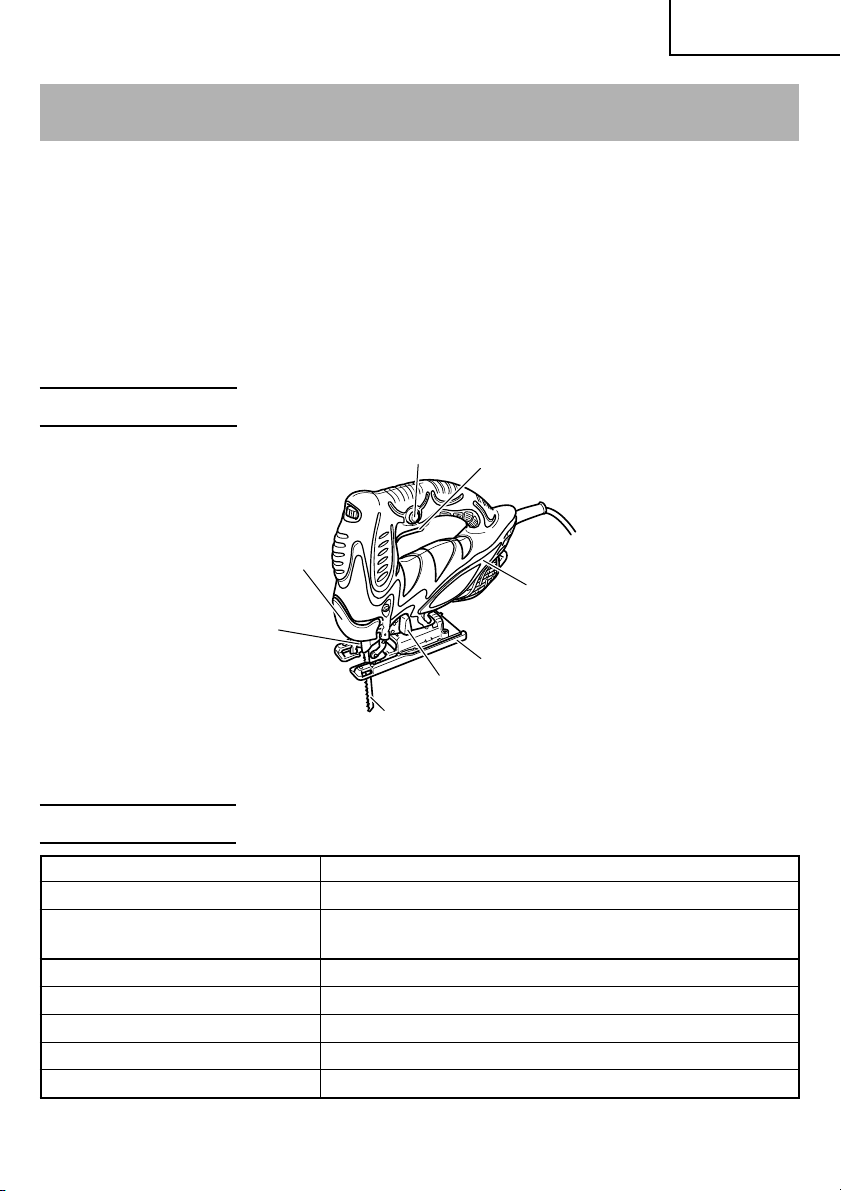
NAME OF PARTS
English
Stopper
Lever
Plunger
Change knob
Blade
Fig. 1
Switch Trigger
Housing
Base
SPECIFICATIONS
Motor Single-Phase, Series Commutator Motor
Power Source Single-Phase, 120V AC 60Hz
Capacity Wood 4-5/16" (110mm)
Mind steel 3/8" (10mm)
Current 5.8A
No-load speed 850 – 3000/min
Stroke 1" (26mm)
Min. cutting radius 1" (25mm)
Weight 4.9 lbs (2.2 kg)
9
Page 10

English
ASSEMBLY AND OPERATION
APPLICATIONS
䡬 Cutting various lumber and pocket cutting
䡬 Cutting mild steel plate, aluminum plate, and copper plate
䡬 Cutting plastics, such as phenol resin and vinyl chloride
䡬 Cutting thin and soft construction materials
䡬 Cutting stainless steel plate (With No. 97 blade)
PRIOR TO OPERATION
1. Power source
Ensure that the power source to be utilized conforms to the power source requirements
specified on the product nameplate.
2. Power switch
Ensure that the switch is in the OFF position. If the plug is connected to a receptacle
while the switch is in the ON position, the power tool will start operating immediately
and can cause serious injury.
3. Extension cord
When the work area is far away from the power source, use an extension cord of
sufficient thickness and rated capacity. The extension cord should be kept as short as
practicable.
WARNING:
Damaged cord must be replaced or repaired.
4. Check the receptacle
If the receptacle only loosely accepts the plug, the receptacle must be repaired. Contact
a licensed electrician to make appropriate repairs.
If such a fautly receptacle is used, it may cause overheating, resulting in a serious
hazard.
5. Confirming condition of the environment:
Confirm that the work site is placed under appropriate conditions conforming to
prescribed precautions.
10
Page 11

English
6. Changing blades
(1) Open the lever up to the stop. (Fig. 3-I)
(2) Remove fitted blade
(3) Insert new blade up to the stop in the balde
holder. (Fig. 3-II)
(4) Close the lever. (Fig. 3-III)
CAUTION:
䡬 Be sure to switch power OFF and disconnect
the plug from the receptacle when changing
blades.
䡬 Do not open the lever when plunger is moving.
NOTE:
䡬 Confirm the protrusions of blade inserted to
the blade holder surely. (Fig. 4)
䡬 Confirm the blade located between the groove
of roller. (Fig. 5)
7. Adjusting the blade operating speed
The jig saw is equipped with the electric control
circuit which enables stepless speed control.
To adjust the speed, turn the dial shown in Fig.
6. When the dial is set to “1”, the jig saw
operates at the minimum speed (850 /min.).
When the dial set to “5”, the jig saw operates
at the maximum speed (3000/min.). Adjust the
speed according to the material to be cut and
working efficiency.
Blade
Blade holder
Lever
Fig. 3
Blade
Blade holder
Fig. 4
Blade Blade
Roller
Roller
CAUTION:
䢇 At low speed (dial setting: 1 or 2) do not cut a
wood with a thickness of more than 3/8" (10
mm) or metal with a thickness of more than
1/32" (1 mm).
8. Adjusting the orbital operation
(1) This Jig Saw employs orbital operation which
moves the blade back and forth, as well as up
and down. Set the change knob shown in Fig.
7 to “0” to eliminate the orbital operation (the
blade moves only up and down). The orbital
operation can be selected in 4 steps from “0”
to “III”.
Fig. 5
Dial
Fig. 6
11
Page 12

English
(2) For the hard material, such as a steel plate, etc.,
decrease the orbital operation. For the soft
material, such as lumber, plastic, etc., increase
the orbital operation to increase work
efficiency. To cut the material accurately,
decrease the orbital operation.
9. Cutting stainless steel plates
This Jig Saw can cut stainless steel plates by
using No. 97 blade. Carefully read “Concerning
cutting of stainless steel plates” for proper
operation.
10. Splinter guard (Sold separately)
Using the splinter guard when cutting wood
materials will reduce splintering of cut
surfaces.
Insert the splinter guard in the space on the
base, and push it completely. (see Fig. 8)
11. Chip cover (Sold separately)
Chip cover prevents chips from flying off and
improves the efficiency of dust collector (Sold
separately).
Insert the chip cover between the base and
lever, and push with a slight pressure until it
catches in place. (Fig. 9)
When removing chip cover, hold both sides of
knob and slightly open until it can be removed
from the Jig Saw.
Change knob
Fig. 7
Splinter
guard
Base
Fig. 8
Lever
Chip cover
NOTE: There is a possibility that chip cover is
frosted when cutting the metal.
12. Sub base (Sold separately)
Using the sub base (made from steel) will
reduce abrasion of aluminium base especially
in cutting metals.
Using the sub base (made from resin) will
reduce scratching of cut surface. Attach the sub
base to the bottom surface of base by attached
4 screws.
13. Lighting up the lamp
CAUTION: Do not look in the light or see the
source of light directly.
To turn on the lamp, pull the trigger.
Release the trigger to turn off.
12
Base
Fig. 9
Page 13

CUTTING
CAUTIONS:
䢇 In order to prevent blade dislodging, damage
or excessive wear on the Plunger, please make
sure to have surface of the base plate attached
to the work piece while sawing.
Base
bolt
English
Base
1. Rectilinear cutting
When cutting on a straight line, first draw a
marking gauge line and advance the saw along
that line. Using the guide (sold separately) will
make it possible to cut accurately on a straight
line.
(1) Loosen the base bolt allen wrench attached on
base. (Fig. 10)
(2) Move the base fully forward (Fig. 11), and
tighten the base bolt again.
(3) Attach the guide by passing it through the
attachment hole on the base and tighten the
M5 bolt. (Fig. 12)
(4) Set the orbital position to “0”.
NOTE: To ensure accurate cutting when using the
Guide (Fig. 10), always set the orbital
position to “0”.
2. Sawing curved lines
When sawing a small circular arc, reduce the
feeding speed of the machine. If the machine
is fed too fast, it could cause the blade to break.
3. Cutting a circle or a circular arc
The guide also will be helpful for circular
cutting.
After attaching the guide by same way noted
as above, drive the nail or screw into the
material through the hole on the guide, then
use it for a axis when cutting. (Fig. 13)
Allen wrench
Fig. 10
Base
Fig. 11
M5 bolt
Attachment
hole
Guide
Fig. 12
NOTE: Circular cutting must be done with the
blade approximately vertical to the bottom
surface of the base.
Guide
Nail screw
Guide
hole
Fig. 13
13
Page 14

English
4. Cutting metallic materials
(1) Adjust the speed Dial between scales “3” and
“4”.
(2) Set the orbital position to “0” or “I”.
(3) Always use an appropriate cutting fluid
(spindle oil, soapy water, etc.). When a liquid
cutting fluid is not avaiable, apply grease to
the back surface of the material to be cut.
5. Pocket cutting
(1) In lumber
Aligning the blade direction with the grain of
the wood, cut step by step until a window hole
is cut in the center of the lumber. (Fig. 14)
(2) In other materials
When cutting a window hole in materials other
than lumber, initially bore a hole with a drill or
similar tool from which to start cutting.
6. Angular cutting
The base can be swiveled to both sides by up
to 45° for angular cutting. (Fig. 15)
(1) Loosen the base bolt by allen wrench attached
on base and move the base fully forward. (Fig.
10, 11)
(2) Align the scale (from 0 degrees to 45 degrees
by 15-degree increments) of the semi-circular
part of the base with the [
cover. (Fig. 16)
(3) Tighten the M5 bolt again. (Fig. 10)
(4) Set the orbital position to “0”.
] mark on the gear
Fig. 14
Base
Fig. 15
mark
NOTE: Angular cutting can not be done when
adopting chip cover or dust collector.
Semi-circular
part
Fig. 16
Scale
CONCERNING CUTTING OF STAINLESS STEEL PLATES
When used with the No. 97 blade, can cut stainless steel plates.
Note the following to adjus the unit.
CAUTION:
䢇 In order to prevent blade dislodging, damage or excessive wear on the Plunger, please
make sure to have surface of the base plate attached to the work piece while sawing.
14
Page 15

When cutting stainless steel plates, adjust the unit as described below:
1. Adjust the speed
Blade Thickness of material Dial Scale
English
No. 97 1/16" – 5/32" (1.5 mm – 2.5 mm)
NOTE: Dial scale reading is for reference only. The higher the speed is, the quicker the
material is cut. But the service life of the blade will be reduced in this case. When
the speed is too low, cutting will take longer, although the service life will be
prolonged. Make adjustments as desired.
Middle groove position
between scales “2” and “3”
2. Set the orbital position to “0”
NOTE: When cutting use cutting fluid (oil base cutting fluid) to prolong the blade’s
service life.
SELECTION OF BLADES
䡬 Accessory blades
To ensure maximum operating efficiency and results, it is very important to select the
appropriate blade best suited to the type and thickness of the material to be cut. Three
types of blades are provided as standard accessories. The blade number is engraved in
the vicinity of the mounting portion of each blade. Select appropriate blades by referring
to Table 1 (page 18).
HOUSING THE ALLEN WRENCH
䡬 It is possible to house the axiliary allen wrench
on the base (see Fig. 17).
I
Allen
wrench
Base
II
Fig. 17
15
Page 16

English
CONNECTING WITH CLEANER
By connecting with cleaner (sold separately)
through dust collection adapter and adapter (sold
separately), most of dust can be collected.
(1) Remove the allen wrench from the base.
(2) Move the base fully forward. (Fig. 10, 11)
(3) Attach the chip cover.
(4) Connect the dust collection adapter with
adapter. (Fig. 18)
(5) Connect the adapter with the nose of cleaner.
(Fig. 18)
(6) Insert dust collection adapter into the rear hole
of the base until the hook catches in the notch.
(Fig. 19)
(7) Press the hook to remove the dust collection
adapter.
Chip
cover
Base
Base
Notch
Rear
hole
Dust collection
adapter
Fig. 18
Hook
Dust
collection
adapter
Fig. 19
Adapter
Nose
Cleaner
Nose
Adapter
16
Page 17

English
MAINTENANCE AND INSPECTION
WARNING: Be sure to switch power OFF and disconnect the plug from the
receptacle during maintenance and inspection.
1. Inspecting the drill bits
Since use of a dull tool will cause motor malfunctioning and degraded efficiency, replace
the drill bit with a new one or resharpening without delay when abrasion is noted.
2. Inspecting the screws
Regularly inspect all screws and ensure that they are properly tightened. Should any of
the screws be loose, retighten them immediately.
WARNING: Using this Jig Saw with loosen screws is extremely dangerous.
3. Maintenance of the motor
The motor unit winding is the very “heart” of the power tool. Exercise due care to
ensure the winding does not become damaged and/or wet with oil or water.
4. Service and repairs
All quality power tools will eventually require servicing or replacement of parts because
of wear from normal use. To assure that only authorized replacement parts will be
used, all service and repairs must be performed by a HITACHI AUTHORIZED SERVICE
CENTER, ONLY.
5. Service parts list
CAUTION: Repair, modification and inspection of Hitachi Power Tools must be carried
out by an Hitachi Authorized Service Center.
This Parts List will be helpful if presented with the tool to the Hitachi
Authorized Service Center when requesting repair or other maintenance. In
the operation and maintenance of power tools, the safety regulations and
standards prescribed in each country must be observed.
MODIFICATIONS:
Hitachi Power Tools are constantly being improved and modified to incorporate the
latest technological advancements.
Accordingly, some parts (i.e. code numbers and/or design) may be changed without
prior notice.
17
Page 18

English
65)
–
2-9/16
–
3/16
–
5)
5/32
2.5)
–
–
–
(1.5
1/16
19/32
15)
–
–
63/64(25)
19/32
15)
–
–
63/64
25)
–
–
25)
63/64
–
–
3/4
40) (10
20)
–
–
–
55) (5
30) (3
1-3/16 1/8
–
–
–
6) 1/8(3) (2
15/64 Below 5/64
–
–
(3
1/8
No. 21 No. 22 No. 41 No. 97
1-9/16 3/8
–
2-5/32 3/16
–
Thickness of material: inch (mm)
Below 3/16
30) 3/8 (10) (5
1-3/16
2-5/32 Below 3/8
No. 11 No. 12 No. 15 No. 16
–
(Super Long)
(Long)
Below Below 3/8
No. 1 No. 1
–
–
(5
(10 – 55) 3/4(20) (10
3/16
5-5/16 (135)
4-1/8 (105)
12) 1/8(3) 3/16(5)
15/32 Below Below
–
–
(3
1/8
up to up to
Height Height
19/32 Below 3/16
15) 1/4(6) (5
–
–
)
3/4 Below 3/16
20) 1/4(6) (5
–
–
(5
3/16
63/64(25
3/4 3/16
20) (5
–
–
30) (3
1-3/16 1/8
–
–
3/4 Below 3/16
20) 3/16(5) (5
–
–
Below 3/16
30) 3/8(10) (5
–
(5
3/16–1-3/16
1-1/2 3/16
–
2-5/32 1/8
–
63/64 3/8
–
63/64 1/8
–
63/64 3/16
–
2-5/32 1/8
–
3/8
40) (5
–
55) (3
–
25) (10
–
25) (3
–
25) (5
–
55) (3
–
(10
40)
1-1/2
–
–
55) (3
–
2-5/32 1/8
–
25) (10
63/64 3/8
–
–
55) (3
–
2-5/32 1/8
–
(10
3/8
63/64 Below 1/8
–
1/8
25) 1/4(6) (3
–
(3
1/4(6)
Below
Blade
Material
quality
General lumber
Plywood
Material
Table 1 List of appropriate blades
18
to be cut
Lumber
Mild steel plate
Stainless steel
plate
Aluminium
copper, brass
Iron plate
Nonferrous
Aluminium sash
Phenol resin,
melamin resin, etc.
Vinyl chloride,
metal
acryl resin, etc.
Foamed polyethyl-
ene, foamed styrol
Card board,
corrugated paper
Plastics
Hardboard
Fiberboard
Pulp
mm).
NOTE:
䡬 The minimum cutting radius of No. 1 (Long), No. 1 ( Super Long), No. 21, No. 22 and No. 41 blades is 3-15/16" (100
䡬 No. 1 (Long), No. 1 ( Super Long), No. 11, No. 12, No. 15, No. 16, No. 21, No. 22 and No. 97 blades are sold separately.
Page 19

English
ACCESSORIES
WARNING: ALWAYS use Only authorized HITACHI replacement parts and
accessories. NEVER use replacement parts or accessories which are
not intended for use with this tool. Contact HITACHI if you are not sure
whether it is safe to use a particular replacement part or accessory
with your tool.
The use of any other attachment or accessory can be dangerous and
could cause injury or mechanical damage.
NOTE: Accessories are subject to change without any obligation on the part of the HITACHI.
STANDARD ACCESSORIES
䡬 No. 41 Blade ......................................................................................................................... 1
䡬 Allen wrench ........................................................................................................................ 1
OPTIONAL ACCESSORIES.....sold separately
䡬 No. 1 Blade (Long) (Code No. 879227)
䡬 No. 1 Blade (Super Long) (Code No. 321878)
䡬 No. 11 Blade (Code No. 963390)
䡬 No. 12 Blade (Code No. 963391)
䡬 No. 15 Blade (Code No. 963392)
䡬 No. 16 Blade (Code No. 963393)
䡬 No. 21 Blade (Code No. 963394)
䡬 No. 22 Blade (Code No. 963395)
䡬 No. 97 Blade (Code No. 963400)
䡬 Guide (Code No. 879391)
䡬 Sub base (Steel) (Code No. 321994)
䡬 Sub base (Resin) (Code No. 321995)
䡬 Special screw (Code No. 321996)
(For installation of the sub base)
䡬 Bench stand (Model TR12-B)
䡬 Splinter guard (Code No. 321590)
䡬 Dust collection adapter (Code No. 321591)
䡬 Chip cover
NOTE: Specifications are subject to change without any obligation on the part of the
HITACHI.
19
Page 20

Français
INFORMATIONS IMPORTANTES DE SÉCURITÉ
Lire et comprendre toutes les précautions de sécurité, les avertissements et les instructions
de fonctionnement dans ce mode d’emploi avant d’utiliser ou d’entretenir cet outil motorisé.
La plupart des accidents causés lors de l’utilisation ou de l’entretien de l’outil motorisé
proviennent d’un non respect des règles ou précautions de base de sécurité. Un accident
peut la plupart du temps être évité si l’on reconnaît une situation de danger potentiel avant
qu’elle ne se produise, et en observant les procédures de sécurité appropriées.
Les précautions de base de sécurité sont mises en évidence dans la section “SECURITE”
de ce mode d’emploi et dans les sections qui contiennent les instructions de fonctionnement
et d’entretien.
Les dangers qui doivent être évités pour prévenir des blessures corporelles ou un
endommagement de la machine sont identifiés par AVERTISSEMENTS sur l’outil motorisé
et dans ce mode d’emploi.
NE JAMAIS utiliser cet outil motorisé d’une manière qui n’est pas spécifiquement
recommandée par HITACHI.
SIGNIFICATION DES MOTS D’AVERTISSEMENT
AVERTISSEMENT indique des situations potentiellement dangereuses qui, si elles sont
ignorées, pourraient entraîner la mort ou de sérieuses blessures.
PRECAUTION indique des situations dangereuses potentilles qui, si elles ne sont pas évitées,
peuvent entraîner de mineures et légères blessures ou endommager la machine.
REMARQUE met en relief des informations essentielles.
20
Page 21

Français
SECURITE
REGLES GENERALE DE SECURITE
AVERTISSEMENT: Lire et coxmprendre toutes les instructions.
Un non respect de toutes les instructions ci-dessous peut
entraîner une électrocution, un incendie et/ou de sérieuses
blessures personnelles.
CONSERVER CES INSTRUCTIONS
1. Zone de travail
(1) Garder la zone de travail propre et bien éclairée. Les établis mal rangés et les zones
sombres invitent aux accidents.
(2) Ne pas utiliser les outils motorisés dans une atmosphère explosive, telle qu’en
présence de liquides inflammables, de gaz ou de poussières. Les outils motorisés
créent des étincelles qui risquent d’enflammer la poussière ou les vapeurs.
(3) Tenir les spectateurs, les enfants et les visiteurs éloignés, lors de l’utilisation de
l’outil motorisé. Une distraction peut faire perdre le contrôle de la machine.
2. Sécurité électrique
(1) Les outils à double isolation sont équipés d’une fiche polarisée (une lame est plus
large que l’autre). Cette fiche ne pénétrera dans une prise secteur polarisée que
dans un sens. Si la fiche ne rentre pas complètement dans la prise, la retourner. Si
elle ne rentre toujours pas, contacter un électricien qualifié pour installer une prise
polarisée. Ne pas modifier la fiche d’aucune façon. La double isolation
besoin d’un cordon d’alimentation à trois fils et d’un système d’alimentation avec
mises à la terre.
(2) Eviter tout contact corporel avec les surfaces mises à la terre telles que les
canalisations, les radiateurs, les réchauds et les réfrigérateurs. Il y a un risque accru
d’électrocution si son corps est mis à la terre.
(3) Ne pas exposer les outils motorisés à la pluie ou à l’humidité. De l’eau pénétrant à
l’intérieur de l’outil motorisé augmente le risque d’électrocution.
(4) Ne pas maltraiter le cordon d’alimentation. Ne jamais utiliser le cordon pour porter
les outils ou tirer sur la fiche du réceptacle. Garder le cordon à l’écart de la chaleur,
de l’huile, des arêtes coupantes ou des pièces en mouvement. Remplacer les cordons
endommagés immédiatement. Des cordons endommagés augmentent le risque
d’électrocution.
(5) Lors de l’utilisation d’un outil motorisé, utiliser un cordon de rallonge extérieur
marqué “W-A” ou “W”. Ces cordons sont prévus pour une utilisation extérieure et
réduisent les risques d’électrocution.
3. Sécurité personnelle
(1) Rester sur ses gardes, regarder ce que l’on fait et utiliser son sens commun lors de
l’utilisation d’un outil motorisé. Ne pas utiliser un outil en état de fatigue ou sous
l’influence de drogues, d’alcool ou de médicaments. Un moment d’inattention lors
de l’utilisation de l’outil motorisé peut entraîner de sérieuses blessures personnelles.
élimine le
21
Page 22

Français
(2) S’habiller correctement. Ne pas porter des vêtements larges ou des bijoux. Attacher
les cheveux longs. Tenir ses cheveux, vêtements et ses gants éloignés des parties
mobiles. Les vêtements larges, les bijoux et les cheveux longs peuvent se prendre
dans les parties mobiles.
(3) Eviter tout démarrage accidentel. S’assurer que le l’interrupteur d’alimentation est
sur la position d’arrêt avant de brancher la machine. Transporter l’appareil avec les
doigts sur l’interrupteur d’alimentation ou brancher un outil avec l’interrupteur sur
la position marche invite aux accidents.
(4) Retirer les clefs d’ajustement ou les commutateurs avant de mettre l’outil sous
tension. Une clef qui est laissée attachée à une partie tournante de l’outil peut
provoquer une blessure personnelle.
(5) Ne pas trop présumer de ses forces. Garder en permanence une position et un
équilibre correct. Une position et un équilibre correct permettent un meilleur contrôle
de l’outil dans des situations inattendues.
(6) Utiliser un équipement de sécurité. Toujours porter une protection pour les yeux.
Utiliser un masque à poussière, des chaussures de sécurité antidérapantes, un casque
dur et une protection pour les oreilles dans les conditions appropriées.
4. Utilisation de l’outil et entretien
(1) Utiliser un étau ou toutes autres façons de fixer et maintenir la pièce à usiner sur
une plate-forme stable. Tenir la pièce avec la main ou contre son corps est instable
et peut conduire à une perte de contrôle de l’outil.
(2) Ne pas forcer sur l’outil. Utiliser l’outil correct pour l’application souhaitée. L’outil
correct réalisera un meilleur et plus sûr travail dans le domaine pour lequel il a été
conçu.
(3) Ne pas utiliser un outil s’il ne se met pas sous ou hors tension avec un interrupteur.
Un outil qui ne peut pas être commandé avec un interrupteur est dangereux et doit
être réparé.
(4) Déconnecter la fiche de la source d’alimentation avant de réaliser tout ajustement,
changement d’accessoires ou pour ranger l’outil. De telles mesures de sécurité
réduisent le risque que l’outil ne démarre accidentellement.
(5) Ranger les outils inutilisés hors de la portée des enfants et des autres personnes
inexpérimentées. Les outils sont dangereux dans les mains de personnes
inexpérimentées.
(6) Utiliser un équipement de sécurité. Toujours porter des lunettes de protection.
Utiliser un masque à poussière, des chaussures de sécurité antidérapantes, un
couvre-chef dur ou des protections de l’ouïe dans les conditions appropriées.
(7) Vérifier les défauts d’alignement ou grippage des parties mobiles, les ruptures des
pièces et toutes les autres conditions qui peuvent affecter le fonctionnement des
outils. En cas de dommage, faire réparer l’outil avant de l’utiliser. Beaucoup
d’accidents sont causés par des outils mal entretenus.
8) Utiliser uniquement les accessoires recommandés par le fabricant pur le modèle
utilisé. Des accessoires qui peuvent convenir à un outil, peuvent devenir dangereux
lorsqu’ils sont utilisés avec un autre outil.
5. Réparation
(1) La réparation de l’outil ne doit être réalisée uniquement par un réparateur qualifié.
Une réparation ou un entretien réalisé par un personnel non qualifié peut entraîner
des risques de blessures.
22
Page 23

Français
(2) Lors de la réparation d’un outil, utiliser uniquement des pièces de rechange
identiques. Suivre les instructions de la section d’entretien de ce mode d’emploi.
L’utilisation de pièces non autorisées ou un non respect des instructions d’entretien
peut créer un risque d’électrocution ou de blessures.
REGLES DE SECURITE SPECIFIQUES ET SYMBOLES
1. Tenir les outils par les surfaces de grippage lors de la réalisation d’opération où l’outil
de coupe risque d’entrer en contact avec des câbles cachés ou son propre cordon. Un
contact avec un fil “sous tension” mettra les parties métalliques de l’outil “sous tension”
et électrocutera l’utilisateur.
2. TOUJOURS porter des protections d’oreille lors de l’utilisation de l’outil pendant de
longues périodes.
Une exposition prolongée à un son de forte intensité peut endommager
l’ouïe de l’utilisateur.
3. NE JAMAIS toucher la mèche avec des mains nues après l’utilisation.
4. NE JAMAIS porter de gants faits d’une matière qui risque de s’enrouler, comme du
coton, de la laine, de la toile ou de la ficelle, etc.
5. TOUJOURS fixer la poignée latérale et tenir fermement le marteau rotatif.
6. NE JAMAIS toucher les parties mobiles.
NE JAMAIS placer ses mains, ses doigts ou toute autre partie de son corps près des
parties mobiles de l’outil.
7. NE JAMAIS utiliser l’outil sans que tous les dispositifs de sécurité ne soient en place.
NE JAMAIS faire fonctionner cet outil sans que tous les dispositifs et caractéristiques
de sécurité ne soient en place et en état de fonctionnement. Si un entretien ou une
réparation nécessite le retrait d’un dispositif ou d’une caractéristique de sécurité,
s’assurer de bien remettre en place le dispositif ou la caractéristique de sécurité avant
de recommencer à utiliser l’outil.
8. Utiliser l’outil correct.
Ne pas forcer sur un petit outil ou accessoire pour faire le travail d’un outil de grande
puissance.
Ne pas utiliser un outil pour un usage pour lequel il n’a pas été prévu: par exemple, ne
pas utiliser une scie circulaire pour couper des branches d’arbre ou des bûches.
9. NE JAMAIS utiliser un outil motorisé pour des applications autres que celles spécifiées.
NE JAMAIS utiliser un outil motorisé pour des applications autres que celles spécifiées
dans le mode d’emploi.
10. Manipuler l’outil correctement.
Utiliser l’outil de la façon indiquée dans ce mode d’emploi. Ne pas laisser tomber ou
lancer l’outil. NE JAMAIS permettre que l’outil soit utilisé par des enfants, des personnes
non familiarisées avec son fonctionnement ou un personnel non autorisé.
23
Page 24

Français
11. Maintenir toutes les vis, tous les boulons et les couvercles fermement en place.
Maintenir toutes les vis, tous les boulons et les couvercles fermement montés. Vérifier
leurs conditions périodiquement.
12. Ne pas utiliser les outils motorisés si le revêtement de plastique ou la poignée est
fendu.
Des fentes dans le revêtement ou la poignée peuvent entraîner une électrocution. De
tels outils ne doivent pas être utilisés avant d’être réparé.
13. Les lames et les accessoires doivent être fermement montés sur l’outil.
Eviter les blessures potentielles personnelles et aux autres. Les lames, les instruments
de coupe et les accessoires qui ont été montés sur l’outil doivent être fixés et serrés
fermement.
14. Garder propres les évents d’air du moteur.
Les évents d’air du moteur doivent être maintenus propres de façon que l’air puisse
circuler librement tout le temps. Vérifier les accumulations de poussière fréquemment.
15. Utiliser l’outil motorisé à la tension nominale.
Utiliser l’outil motorisé à la tension spécifiée sur sa plaque signalétique.
Si l’on utilise l’outil motorisé avec une tension supérieure à la tension nominale, il en
résultera une rotation anormalement trop rapide du moteur et cela risque
d’endommager l’outil et le moteur risque de griller.
16. NE JAMAIS utiliser un outil défectueux ou qui fonctionne anormalement.
Si l’outil n’a pas l’air de fonctionner normalement, fait des bruits étranges ou sans cela
paraît défectueux, arrêter de l’utiliser immédiatement et le faire réparer par un centre
de service Hitachi autorisé.
17. NE JAMAIS laisser fonctionner l’outil sans surveillance. Le mettre hors tension.
Ne pas abandonner l’outil avant qu’il ne soit complètement arrêté.
18. Manipuler l’outil motorisé avec précaution.
Si un outil motorisé tombe ou frappe un matériau dur accidentellement, il risque d’être
déformé, fendu ou endommagé.
19. Ne pas essuyer les parties en plastique avec du solvant.
Les solvants comme l’essence, les diluants, la benzine, le tétrachlorure de carbone et
l’alcool peuvent endommager et fissurer les parties en plastique. Ne pas les essuyer
avec de tels solvants.
Essuyer les parties en plastique avec un chiffon doux légèrement imbibé d’une solution
d’eau savonneuse et sécher minutieusement.
20. TOUJOURS porter des lunettes de protection qui respectent les dernières révisions du
Standard ANSI Z87.1.
21. TOUJOURS vérifier s’il y a des objets encastrés par exemple des fils électriques.
Le fait de toucher avec l’outil un fil ou un câble électrique sous tension encastré dans le
mur risque de provoquer une décharge électrique.
Vérifier s’il y des objets encastrés, par exemple un câble électrique, dans le mur, le
plancher ou le plafond avant d’y commencer le travail.
24
Page 25

Français
22. Cette machine utilise un moteur à puissance élevée. Si la machine est utilisée
continuellement à faible vitesse, une charge supplémentaire est appliquée au moteur
et peut en provoquer son mauvais fonctionnement. Toujours utiliser la scie de façon à
ne pas coincer la lame dans la pièce lors de son usage. Toujours régler la vitesse de la
lame pour permettre une coupe en douceur.
23. Définitions pour les symboles utilisés sur cet outil
V ............ volts
Hz .......... hertz
A ............ ampères
no .......... vitesse sans charge
W ........... watt
.......... Construction de classe II
---/min ... rotation ou mouvements de va-et-vient par minute
.......... Courant alternatif
DOUBLE ISOLATION POUR UN FONCTIONNEMENT PLUS SUR
Pour assurer un fonctionnement plus sûr de cet outil motorisé, HITACHI a adopté une
conception à double insolation. “Double isolation” signifie que deux systèmes d’isolation
physiquement séparés ont été utilisés pour isoler les matériaux conducteurs d’électricité
connectés à l’outil motorisé à partir du cadre extérieur manipulé par l’utilisateur. C’est
pourquoi, le symbole “
sur l’outil motorisé ou sur la plaque signalétique.
Bien que ce système n’ait pas de mise à terre extérieure, il est quand même nécessaire de
suivre les précautions de sécurité électrique données dans ce mode d’emploi, y-compris
de ne pas utiliser l’outil motorisé dans un environnement humide.
Pour garder le système de double isolation effectif, suivre ces précautions:
䡬 Seuls les CENTRES DE SERVICE AUTORISES HITACHI peuvent démonter et remonter
cet outil motorisé et uniquement des pièces de rechange HITACHI garanties d’origine
doivent être utilisées.
䡬 Nettoyer l’extérieur de l’outil motorisé uniquement avec un chiffon doux légèrement
imbibé d’une solution savonneuse et essuyer minutieusement.
Ne jamais utiliser des solvants, de l’essence ou des diluants sur les parties en plastique;
sinon le plastique risquerait de se dissoudre.
” ou les mots “Double insulation” (double isolation) apparaissent
CONSERVER CES INSTRUCTIONS
ET
LES METTRE A LA DISPOSITION
DES AUTRES UTILISATEURS
ET
PROPRIETAIRES DE CET OUTIL!
25
Page 26

Français
DESCRIPTION FONCTIONNELLE
REMARQUE:
Les informations contenues dans ce mode d’emploi sont conçues pour assister
l’utilisateur dans une utilisation sans danger et un entretien de l’outil motorisé.
NE JAMAIS utiliser ni entreprendre une révision de l’outil sans avoir d’abord lu et
compris toutes les instructions de sécurité contenues dans ce manuel.
Certaines illustrations dans ce mode d’emploi peuvent montrer des détails ou des
accessoires différents de ceux de l’outil motorisé utilisé.
NOM DES PARTIES
Butée
Levier
Plongeur
Bouton de changement
Lame
Fig. 1
Gâchette
Bôtier
Base
SPECIFICATIONS
Moteur Moteur série monophasé à collecteur
Source d’alimentation Secteur, 120V 60 Hz, monophasé
Capacité Bois 4-5/16” (110mm)
Acier doux 3/8” (10mm)
Courant 5.8A
Vitesse sans charge 850 – 3000/min
Course 1” (26 mm)
Rayon min. de coupe 1” (25 mm)
Poids 4.9 lbs (2.2 kg)
26
Page 27

Français
ASSEMBLAGE ET FONCTIONNEMENT
APPLICATIONS
䡬 Coupe de différentes sortes de bois de charpente et découpe d’ouvertures
䡬 Coupe de plaques en acier doux, plaques en aluminium et en cuivre
䡬 Coupe de résines synthétiques comme résine phénolique et chlorure de vinyl
䡬 Coupe de matériaux de construction peu épais et tendres
䡬 Coupe de plaque dácier inoxydable (avec la lame No. 97)
AVANT L’UTILISATION
1. Source d’alimentation
S’assurer que la source d’alimentation qui doit être utilisée est conforme à la source
d’alimentation requise spécifiée sur la plaque signalétique du produit.
2. Interrupteur d’alimentation
S’assurer que l’interrupteur est sur la position OFF (arrêt). Si la fiche est connectée sur
une prise alors que l’interrupteur est sur la position ON (marche), l’outil motorisé
démarrera immédiatement risquant de causer de sérieuses blessures.
3. Cordon prolongateur
Quand la zone de travail est éloignée de la source d’alimentation, utiliser un cordon
prolongateur d’épaisseur et de capacité nominale suffisante. Le cordon prolongateur
doit être aussi court que possible.
AVERTISSEMENT:
Tout cordon endommagé devra être remplacé ou réparé.
4. Vérifier la prise
Si la prise reçoit la fiche avec beaucoup de jeu, elle doit être réparée. Contacter un
électricien licencié pour réaliser les réparations nécessaires.
Si une telle prise défectueuse est utilisée, elle peut causer une surchauffe entraînant
des dangers sérieux.
5. Vérification des conditions d’environnement
Vérifier que l’état de l’aire de travail est conforme aux précautions.
27
Page 28

Français
6. Remplacement des lames
(1) Ouvrir le levier jusqu’à la butée. (Fig. 3-I)
(2) Retirer la lame.
(3) Insérer la nouvelle lame jusqu’à la butée dans
le support de lame. (Fig. 3-II)
(4) Refermer le levier. (Fig. 3-III)
PRECAUTIONS:
䡬 Bien mettre l’interrupteur sur OFF et d
ébrancher la fiche de la prise secteur avant de
remplacer les lames.
䡬 Ne pas ouvrir le levier pendant que le plongeur
bouge.
REMARQUE:
䡬 S'assurer que les saillies de la lame rentrent à
fond dans le support de lame. (Fig. 4)
䡬 S’assurer que la lame est située dans la rainure
du rouleau. (Fig. 5)
7. Réglage de la vitesse de fonctionnement
de la lame
La scie sauteuse est équipée d’un circuit de
contrôle électrique qui permet un contrôle de
vitesse progressif.
Pour régler la vitesse, tourner le cadran montré
à la Fig. 6. Quand la cardran est réglé sur “1”,
la scie sauteuse fonctionne à la vitesse
minimale (850/min).
Quaned le cadran est réglé sur “5” la sauteuse
fonctionne à la vitesse maximale (3000/min).
Régler la vitesse suivant le matériel devant être
coupé et le rendment de travail.
Fig. 3
Support de lame
Fig. 4
Lame
Rouleau
Lame
Support
de lame
Levier
Lame
Lame
Rouleau
ATTENTION:
䢇 A petite vittesse (réglage de l’échelle sur: 1 ou
2), ne pas couper une pièce de bois ayant plus
de 3/8” (10 mm) d’épaisseur ou une pièce
d’acier ayant plus de 1/32” (1 mm) d’épaisseur.
8. Réglage du fonctionnement orbital
(1) La sice sauteuse utlise un fonctionnement
orbital qui déplace la lame tout aussi bien
d’avant en arrière que de haut en bas. Régler
le bouton de changement montré à la Fig. 7
sur “0” pour minimiser le fonctionnement
orbital (la lame ne se déplace que de haut en
bas). Le fonctionnement orbital peut être
sélectionné en quatres étapes de “0” à “III”.
28
Fig. 5
Cadran
Fig. 6
Page 29

(2) Pour les matériaux durs, tels que plaques
d’acier, etc., réduire le fonctionnement orbital.
Pour les matériaux moux, tels que bois de
charpente, matières plastiques, etc.,
augmenter le fonctionnement orbital pour
acroître le rendement du travail. Pour couper
les matériaux avec précision, réduire le
fonctionnement orbital.
9. Découpage de plaques en acier
inoxydable
Cette scie à chantourner pourra couper des
plaques d’acier inoxydable si l’on utilise la
lame No. 97. Lire avec attention la partie
intitulée “Au sujet du découpage de plaques
en acier imoxydable” pour un fonctionnement
correct.
10. Anti-éclats (Vendu séparément)
L’utilisation de l’anti-éclats pendant la découpe
de matériaux en bois réduit considérablement
les éclats de copeaux.
Insérer l’anti-éclats dans l’espace sur la base,
et le pousser à fond. (Voir Fig. 8)
11. Couvercle d’éclats (Vendu séparément)
Le couvercle d’éclats empêche les copeaux
d’être projetés et améliore le rendement du
collecteur à poussière (Vendu séparément).
Insérer le couvercle d’éclats entre la base et le
levier, et appuyer légèrement dessus jusqu’à
ce qu’il se mette en place. (Fig. 9)
Pour retirer le couvercle d’éclats, tenir le
bouton des deux côtés et l’ouvrir légèrement
jusqu’à ce qu’il se dé tache de la scie à
chantourner.
Français
Bouton de changement
Fig. 7
Anti-éclats
Base
Fig. 8
Levier
Couvercle
d’éclats
Base
Fig. 9
REMARQUE: Il est possible que le couvercle
d'éclats se givre lors de la coupe de
métal.
12. Socle auxiliaire (Vendu séparément)
L'utilisation du socle auxiliaire (en acier)
réduira l'abrasion du socle en aluminium, en
particulier lors de la coupe de métaux.
L'utilisation du socle auxiliaire (en résine)
réduira les rayures de la surface de coupe. Fixer
le socle auxiliaire sur le fond du socle à l'aide
des 4 vis.
29
Page 30

Français
13. Allumer la lampe
PRECAUTION: Ne fixez pas la lumière ou la
source de lumière
directement.
Pour allumer la lampe, appuyez sur la gâchette.
Pour l’éteindre, relâchez la gâchette.
COUPE
PRECAUTION:
䢇 Pour éviter un délogement de la lame, des
dommages ou une usure excessive du
plongeur, bien fixer la surface de la plaque du
socle à la pièce pendant le sciage.
1. Coupe rectilinéaire
Pour couper en ligne droite, dessiner tout
d’abord une ligne de repère et avancer la scie
le long de cette ligne. L’utilisation du guide
(vendu séparément) permettra de couper très
précisément en ligne droite.
(1) Desserrer le boulon de la base avec la clé allen
fixée à la base. (Fig. 10)
(2) Déplacer la base à fond vers l’avant (Fig. 11),
puis resserrer le boulon de la base.
(3) Fixer le guide en le faisant passer dans l’orifice
de fixation de la base et serrer le boulon M5.
(Fig. 12)
(4) Régler la position orbitale sur “0”.
REMARQUE: Pour assurer une coupe précise lors
de l'utilisation du guide (Fig. 10),
toujours régler la position orbitale
sur “0”.
Base
Boulon
de la
base
Clef allen
Fig. 10
Fig. 11
Base
2. Sciage de lignes courbes
Pour scier un peit arc circulaire, réduire la
vitesse d’alimentation de la machine. Une
vitesse trop rapide pourrait provoquer la
rupture de la lame.
30
Boulon
M5
Orifice de
fixation
Guide
Fig. 12
Page 31

3. Coupe d’un cercle ou d’un arc circulaire
Le guide est également utile pour la coupe en
cercle.
Après avoir fixé le guide de la même façon
qu’expliqué ci-dessus, faire passer le clou ou
la vis dans la pièce par l’orifice du guide, puis
l’utiliser comme axe pour la coupe. (Fig. 13)
Français
Clou ou vis
REMARQUE: La coupe en cercle doit être effectuée
avec la lame placée environ à la
verticale par rapport à la surface du
fond de la base.
4. Coupe de matériaux métalliques:
(1) Régler la bague de vitesse entre les échelles
“3” et “4”.
(2) Régler la position orbitale sur “0” ou “I”.
(3) Toujours utiliser un liquide de coupe approprié
(huile à broche, eau savonneuse, etc.). Si l'on
ne possède pas de liquide de coupe, appliquer
de la graisse sur la surface arrière du matériau
à couper.
5. Découpe d’ouvertures
(1) Dans du bois de charpente:
En alignant la direction de la lame sur le grain
du bois, couper morceau par morceau jusqu’à
ce qu’une ouverture soit coupée au centre du
bois. (Fig. 14)
(2) Dans d’autres matériaux:
Pour couper une ouverture dans des matériaux
autres que le bois de charpente, percer d’abord
un trou avec une perceuse ou un outil similaire
à partir duquel commencera la coupe.
6. Coupe angulaire
La base peut pivoter de 45° des deux côtés pour
la coupe angulaire. (Fig. 15)
(1) Desserrer le boulon de la base avec la clé allen
hexagonale fixée à la base. (Fig. 10, 11)
(2) Aligner l’échelle (de 0 degré à 45 degrés par
incréments de 15 degrés) de la section semi-
circulaire de la base sur le repère [
couvercle du réducteur. (Fig. 16)
(3) Resserrer le boulon M5. (Fig. 10)
(4) Régler la position orbitale sur “0”.
REMARQUE: La coupe angulaire n’est pas
possible si l’on fixe le couvercle
d’éclats ou le collecteur à poussière.
] du
Guide
Section
semicirculaire
Orifice de
guidage
Fig. 13
Fig. 14
Fig. 15
Fig. 16
Base
Repère
Echelle
31
Page 32

Français
AU SUJET DU DECOUPAGE DE PLAQUES EN ACIER INOXYDABLE
Avec la lame No. 97, il sera possible de couper des tôles d’acier inoxydable.
Pour le réglage de l’outil, noter les points suivants.
PRECAUTION:
䢇 Pour éviter un délogement de la lame, des dommages ou une usure excessive du
plongeur, bien fixer la surface de la plaque du socle à la pièce pendant le sciage.
En coupant des plaques en acier inoxidable, régler l’appareil de la façon suivante.
1. Pour régler la vitesse
Lame Epaisseur du matériau Echelle du cadran gradué
A positionner sur le sillon à mi-
No. 97 1/16“ – 5/32“ (1.5 mm – 2.5 mm)
REMARQUE: L’échelle du cadran gradué n’est qu’une référence. Plus la vitesse est élevée,
le plus rapidement sera coupé le matériau, mais la durée de vie de la lame
sera réduite dans ce cas là. Lorsque la vitesse est réduite, la coupe prendra
plus de temps, mais la durée de vie sera prolongée. Faire les ajustements
selon préférence.
2. Régler la position orbitale sur “0”
chemin entre les graduations “2” et
“3”
REMARQUE: En coupant, faire usage de fluide de coupe (fluide de coupe à base d’huile)
pour prolonger la durée de vie de la lame.
CHOIX DES LAMES
䡬 Lames accessoires
Pour obtenir un fonctionnement optimal et les meillleurs résultats possibles, il est très
important de choisir la lame la mieux appropriée au type et à l’épaisseur du matériau à
couper. Trois modèles de lame sont fournies comme accessoires standards. Le numéro
de lame est gravé près de la section de montage de chaque lame. Choisir les lames
appropriées en se référant au Tableau 1. (Page 35)
32
Page 33

RANGEMENT DES LAMES DE LA
CLÉ ALLEN
䡬 Il est possible de ranger la clé allen dans la
base (voir Fig. 17).
RACCORDEMENT AU NETTOYEUR
Français
I
Clé allen
II
Base
Fig. 17
Si l’on raccorde le nettoyeur (vendu séparément)
par le adaptateur pour collecteur de poussière et
l’adaptateur (vendus séparément), on pourra
recueillir la plus grande partie des poussières.
(1) Retirer la clé allen de la base.
(2) Déplacer la base à fond vers l’avant. (Fig. 10,
11)
(3) Fixer le couvercle d'éclats.
(4) Raccorder le adaptateur pour collecteur de
poussière à l’adaptateur. (Fig. 18)
(5) Raccorder l’adaptateur au bec du nettoyeur.
(Fig. 18)
(6) Insérer le adaptateur pour collecteur de
poussière dans l’orifice arrière de la base
jusqu’à ce que le crochet s’enclenche dans la
rainure. (Fig. 19)
(7) Appuyer sur le crochet pour retirer le
adaptateur pour collecteur de poussière.
Couvercle
d’éclats
Base
Rainure
Base
Orifice
arrière
Adaptateur
Bec
Adaptateur pour
collecteur de poussière
Fig. 18
Crochet
Adaptateur
pour
collecteur
de
poussière
Fig. 19
Adaptateur
Nettoyeur
Bec
33
Page 34

Français
ENTRETIEN ET INSPECTION
AVERTISSEMENT: S’assurer de mettre l’interrupteur d’alimentation sur la
position OFF et de déconnecter la fiche de la prise secteur
avant l’entretien et l’inspectio.
1. Contrôle du foret de perçage
Etant donné que l’utilisation d’une mèche usée entraînera un mauvais fonctionnement
du moteur et une diminution de l’efficacité, remplacez la mèche usée par une neuve ou
aiguisez-la immédiatement et dès que vous notez une certaine usure.
2. Inspection des vis
Inspecter régulièrement toutes les vis et s’assurer qu’elles sont correctement serrées.
Si l’une des vis était desserrée, la resserrer immédiatement.
AVERTISSEMENT: Utiliser la scie sauteuse avec des vis desserrées est
extrêmement dangereux.
3. Entretien du moteur
Le bobinage de l’ensemble moteur est le “coeur” même de l’outil électro-portatif. Veiller
soigneusement à ce que ce bobinage ne soit pas endommagé et/ou mouillé par de
l’huile ou de l’eau.
4. Entretien et reparation
Tous les outils motorisés de qualité auront éventuellement besoin d’une réparation ou
du remplacement d’une pièce à cause de l’usure normale de l’outil. Pour assurer que
seules des pièces de rechange autorisées seront utilisées, tous les entretiens et les
réparations doivent être effectués uniquement par UN CENTRE DE SERVICE HITACHI
AUTORISE.
5. Liste des pièces de rechange
PRECAUTION: Les réparations, modifications et inspections des outils électriques
Hitachi doivent être confiées à un service après-vente Hitachi agréé.
Il sera utile de présenter cette liste de pièces au service après-vente
Hitachi agréé lorsqu’on apporte un outil nécessitant des réparations
ou tout autre entretien. Lors de l’utilisation et de l’entretien d’un
outil électrique, respecter les règlements et les normes de sécurité
en vigueur dans le pays en question.
MODIFICATIONS:
Les outils électriques Hitachi sont constamment améliorés et modifiés afin d’incorporer
les tous derniers progrès technologiques.
En conséquence, il est possible que certaines pièces (c.-à-d. no. de code et/ou dessin)
soient modifiées sans avis préalable.
34
Page 35

Français
65)
–
2-9/16
–
40) (10
1-9/16 3/8
–
–
55) (5
–
2-5/32 3/16
No. 21 No. 22 No. 41 No. 97
–
ériau: pouces (mm)
Epaisseur du mat
55) 3/4(20) (10
–
2-5/32 Moins 3/8
–
No. 11 No. 12 No. 15 No. 16
(10
3/4
20)
–
–
30) (3
1-3/16 1/8
–
–
Moins 3/16
30) 3/8 (10) (5
–
(5
3/16–1-3/16
3/16
5)
–
–
5/64
Moins
6) 1/8(3) (2
15/64
–
–
(3
1/8
5/32
–
1/16
2,5)
–
(1,5
Moins Moins
12) 1/8(3) 3/16(5)
15/32
–
–
(3
1/8
19/32
15)
–
–
63/64(25)
19/32 Moins 3/16
15) 1/4(6) (5
–
–
)
3/4 Moins 3/16
20) 1/4(6) (5
–
jusqu’à jusqu’à
Hauteur allant Hauteur allant
–
(5
3/16
63/64(25
19/32
15)
–
–
3/4 3/16
20) (5
–
–
30) (3
1-3/16 1/8
–
–
3/4 Moins 3/16
20) 3/16(5) (5
–
–
30) 3/8(10) (5
–
(5
3/16–1-3/16 Moins 3/16
63/64
25)
–
–
40) (5
1-1/2 3/16
–
–
55) (3
–
2-5/32 1/8
–
25) (10
63/64 3/8
–
–
63/64 1/8
25) (3
–
–
25) (5
63/64 3/16
–
–
55) (3
–
2-5/32 1/8
–
(10
3/8
1-1/2
–
2-5/32 1/8
–
63/64 3/8
–
2-5/32 1/8
–
3/8
40)
–
55) (3
–
25) (10
–
55) (3
–
(10
25)
63/64
–
–
25) 1/4(6) (3
63/64 Moins 1/8
–
–
(3
1/8
1/4(6)
Moins
éparément.
No.1
(Super Long)
ées
(Long)
Moins Moins 3/8
4-1/8 (105) 5-5/16 (135)
No. 1
Lame
Qualité
du matériau
Bois de charpente
géneral
Contreplaqué
Matériau
Tableau 1 Liste des lames appropri
à couper
Bois de
charpente
Plaque en acier
douz
Plaque en acier
inoxydable
Auminium, cuivre,
lation
Plaque
en fer
Métal
Chassis en
aluminium
Résine phénolique,
nonferreux
Polyéthylène mousseux,
ésine mélamine, etc.
Chlorure de vinyl,
Matières
styrène mousseux
résine acrylique, etc.
plastiques
Carton, papier
ondulé
Isorel
Panneau fibreux
Pulpe
REMARQUE:
䡬 Le rayon de coupe minimal des lames No. 1 (Long), No. 1 (Super Long), No. 21, No. 22 et No. 41 est de 100 mm.
䡬 Les lames No. 1 (Long), No. 1 (Super Long), No. 11, No. 12, No. 15, No. 16, No. 21, No. 22 et No. 97 sont vendues s
35
Page 36

Français
ACCESSOIRES
AVERTISSEMENT: TOUJOURS utiliser UNIQUEMENT des pièces de rechange
et des accessoires HITACHI. Ne jamais utiliser de pièce de
rechange ou d’accessoires qui ne sont pas prévus pour être
utilisé avec cet outil. En cas de doute, contacter HITACHI
pour savoir si une pièce de rechange ou un accessoire
particulier peuvent être utilisés en toute sécurité avec votre
outil.
L’utilisation de tout autre attachement ou accessoire peut
être dangereux et peut causer des blessures ou des
dommages mécaniques.
REMARQUE: Les accessoires sont sujets à changement sans obligation de la part de
HITACHI.
ACCESSOIRES STANDARD
䡬 No. 41 Lame ........................................................................................................................ 1
䡬 Clé Allen .............................................................................................................................. 1
ACCESSOIRES SUR OPTION.....vendus séparément
䡬 No. 1 Lame (Long) (No. de code 879227)
䡬 No. 1 Lame (Super Longue) (No. de code 321878)
䡬 No. 11 Lame (No. de code 963390)
䡬 No. 12 Lame (No. de code 963391)
䡬 No. 15 Lame (No. de code 963392)
䡬 No. 16 Lame (No. de code 963393)
䡬 No. 21 Lame (No. de code 963394)
䡬 No. 22 Lame (No. de code 963395)
䡬 No. 97 Lame (No. de code 963400)
䡬 Guide (No. de code 879391)
䡬 Socle auxiliaire (Acier) (No. de code 321994)
䡬 Socle secondaire (Résine) (No. de code 321995)
䡬 Vis spéciale (No. de code 321996)
(Pour l'installation du socle secondaire)
䡬 Etabli (Modèle TR12-B)
䡬 Anti-éclats (No. de code 321590)
䡬 Adaptateur pour collecteur de poussière (No. de code 321591)
䡬 Couvercle d'éclats
REMARQUE: Les spécifications sont sujettes à modification sans aucune obligation de la
part de HITACHI.
36
Page 37

Español
INFORMACIÓN IMPORTANTE SOBRE SEGURIDAD
Antes de utilizar o de realizar cualquier trabajo de mantenimiento de esta herramienta
eléctrica, lea y comprenda todas las precauciones de seguridad, advertencias e instrucciones
de funcionamiento de este Manual de instrucciones.
La mayoría de los accidentes producidos en la operación y el mantenimiento de una
herramienta eléctrica se deben a la falta de observación de las normas o precauciones de
seguridad. Los accidentes normalmente podrán evitarse reconociendo una situación
potencialmente peligrosa a tiempo y siguiendo los procedimientos de seguridad apropiados.
Las precauciones básicas de seguridad se describen en la sección “SEGURIDAD” de este
Manual de instrucciones y en las secciones que contienen las instrucciones de operación y
mantenimiento.
Para evitar lesiones o el daño de la herramienta eléctrica, los riesgos están identificados
con ADVERTENCIAS en dicha herramienta y en este Manual de instrucciones.
NO utilice NUNCA esta herramienta eléctrica de ninguna forma que no esté específicamente
recomendada por HITACHI.
SIGNIFICADO DE LAS PALABRAS DE SEÑALIZACIÓN
ADVERTENCIA indica situaciones potencialmente peligrosas que, si se ignoran, pueden
resultar en la muerte o en lesiones de gravedad.
PRECAUCIÓN indica situaciones potencialmente peligrosas que, de no evitarse, pueden
resultar en lesiones menores o moderadas, o causar daños en la herramienta eléctrica.
NOTA acentúa información esencial.
37
Page 38

Español
SEGURIDAD
NORMAS GENERALES DE SEGURIDAD
ADVERTENCIA: Lea y entienda todas las instrucciones.
Si no sigue las instrucciones indicadas a continuación,
pueden producirse descargas eléctricas, incendios, y/o lesiones
serias.
GUARDE ESTAS INSTRUCCIONES
1. Área de trabajo
(1) Mantenga el área de trabajo limpia y bien iluminada. Los bancos de trabajo
desordenados y las áreas obscuras pueden conducir a accidentes.
(2) No utilice la herramienta en atmósferas explosivas, como en presencia de líquidos
inflamables, gases, o polvo. La herramienta eléctrica crea chispas que pueden
incendiar polvo o gases.
(3) Mantenga alejadas a otras personas, niños o visitantes, cuando utilice la herramienta
eléctrica. Las distracciones pueden hacer que pierda el control de la herramienta.
2. Seguridad eléctrica
(1) Las herramientas eléctricas con aislamiento doble poseen un enchufe polarizado
(una cuchilla es más ancha que la otra). Este enchufe encajará en un tomacorriente
polarizado de una sola forma. Si el enchufe no entra completamente en el
tomacorriente, invierta su sentido de inserción. Si sigue sin entrar, póngase en
contacto con un electricista cualificado para que le instale un tomacorriente
polarizado. No cambie nunca el enchufe. El aislamiento doble
de un cable de alimentación de tres conductores, uno para puesta a tierra, y del
sistema de alimentación con puesta a tierra.
(2) Evite el contacto con superficies con puesta a tierra, tales como tubos, radiadores,
hornos, y refrigeradores. Si toca tierra, existe el peligro de que reciba una descarga
eléctrica.
(3) No exponga la herramienta eléctrica a la lluvia ni a la humedad. La entrada de agua
en la herramienta eléctrica aumentará el riesgos de descargas eléctricas.
(4) No maltrate el cable de alimentación. No utilice nunca el cable de alimentación
para transportar la herramienta ni para desconectarla del tomacorriente. Mantenga
el cable alejado del calor, aceite, bordes cortantes, o partes móviles. Reemplace
inmediatamente cualquier cable dañado. Un cable dañado puede ser la causa de
descargas eléctricas.
(5) Cuando utilice la herramienta eléctrica en exteriores, utilice un cable prolongador
marcado con “W-A” o “W”. Estos cables han sido diseñados para utilizarse en
exteriores y reducir el riesgo de descargas eléctricas.
3. Seguridad personal
(1) Esté siempre alerta y utilice el sentido común cuando utilice la herramienta eléctrica.
No utilice la herramienta cuando esté cansado o bajo la influencia de medicamentos
ni de alcohol. Un descuido al utilizar la herramienta eléctrica puede resultar en una
38
lesión seria.
elimina la necesidad
Page 39

Español
(2) Vístase adecuadamente. No utilice ropa floja ni joyas. Si tiene pelo largo, recójaselo.
Mantenga su pelo, ropa, y guantes alejados de las partes móviles. La ropa floja, las
joyas, o el pelo largo pueden engancharse en las partes móviles.
(3) Evite la puesta en marcha accidental. Cerciórese de que la alimentación de la
herramienta eléctrica esté desconectada antes de enchufarla en una toma de la
red. Si lleva la herramienta eléctrica con el dedo colocado en el interruptor, o si la
enchufa con dicho interruptor cerrado, es posible que se produzcan accidentes.
(4) Quite las llaves de ajuste y abra los interruptores antes de poner en funcionamiento
la herramienta. Una llave dejada en una parte móvil de la herramienta podría resultar
en lesiones.
(5) No sobrepase su alcance. Mantenga en todo momento un buen equilibrio. El
conservar en todo momento el equilibrio le permitirá controlar mejor la herramienta
en situaciones inesperadas.
(6) Utilice equipos de seguridad. Utilice siempre protección ocular. Para conseguir las
condiciones apropiadas, utilice una mascarilla contra el polvo, zapatos no
resbaladizos o protección auditiva.
4. Utilización y cuidados de la herramienta
(1) Utilice abrazaderas u otra forma práctica de asegurar y sujetar la pieza de trabajo
sobre una plataforma estable. La sujeción de la pieza de trabajo con la mano o
contra su cuerpo puede ser inestable y conducir a la pérdida del control.
(2) No fuerce la herramienta. Utilice la herramienta correcta para su aplicación. Con la
herramienta correcta realizará mejor el trabajo y ésta será más segura para la
velocidad para la que ha sido diseñada.
(3) No utilice la herramienta si el interruptor de alimentación de la misma no funciona.
Cualquier herramienta que no pueda controlarse con el interruptor de alimentación
puede resultar peligrosa, y deberá repararse.
(4) Desconecte el enchufe del cable de alimentación antes de realizar cualquier ajuste,
cambiar accesorios, o guardar la herramienta. Tales medidas preventivas de
seguridad reducirán el riesgo de que la herramienta se ponga en funcionamiento
accidentalmente.
(5) Guarde las herramientas que no vaya a utilizar fuera del alcance de niños y de otras
personas no entrenadas. Las herramientas son peligrosas en manos de personas
inexpertas.
(6) Realice el mantenimiento cuidadoso de las herramientas. Mantenga las
herramientas afiladas y limpias. Las herramientas adecuadamente mantenidas, con
los bordes cortantes afilados, serán más fáciles de utilizar y controlar.
(7) Compruebe que las piezas móviles no estén desalineadas ni atascadas, que no
hayan piezas rotas, y demás condiciones que puedan afectar la operación de las
herramientas. En caso de que una herramienta esté averiada, repárela antes de
utilizarla. Muchos de los accidentes se deben a herramientas mal cuidadas.
(8) Utilice solamente los accesorios recomendados por el fabricante para su modelo.
Los accesorios adecuados para usar con una herramienta pueden ser peligrosos
cuando se utilicen con otra.
5. Servicio de reparación
(1) El servicio de reparación deberá realizarlo solamente personal cualificado. El servicio
de mantenimiento o reparación realizado por persona no cualificado podría resultar
en el riesgo de lesiones.
39
Page 40

Español
(2) Para el servicio de mantenimiento o reparación de una herramienta, utilice
solamente piezas de repuesto idénticas. Siga las instrucciones de la sección de
mantenimiento de este manual. La utilización de piezas no autorizadas, o el no
seguir las indicaciones del Manual de instrucciones puede crear el riesgo de
descargas eléctricas u otras lesiones.
NORMAS Y SÍMBOLOS ESPECÍFICOS DE SEGURIDAD
1. Sujete las herramientas por las superficies de empuñadura aisladas cuando realice
una operación en la que la herramienta de corte pueda entrar en contacto con cables
ocultos o con su propio cable de alimentación. El contacto con un conductor “activo”
“activará” las partes metálicas de la herramienta y el operador recibirá una descarga
eléctrica.
2. SIEMPRE utilice protectores auditivos cuando tenga que utilizar la herramienta du-
rante mucho tiempo.
La exposición prolongada a ruido de gran intensidad puede causar la
sordera.
3. NO toque NUNCA una broca de la herramienta con las manos desnucas después de la
operación.
4. NO utilice NUNCA guantes hechos de material que pueda quedar pillado en la
herramienta, como algodón, lana, paño, cuerda, etc.
5. Fije SIEMPRE la empuñadunral lateral y sujete con seguridad el martillo giratorio.
6. NO toque NUNCA las piezas móviles.
NO coloque NUNCA sus manos, dedos, ni demás partes del cuerpo cerca de las piezas
móviles de la herramienta.
7. NO utilice NUNCA la herramienta sin los protectores colocados en su lugar.
NO utilice NUNCA esta herramienta sin los protectores de seguridad correctamente
instalados. Si el trabajo de mantenimiento o de reparación requiere el desmontaje de
un protector de seguridad, cerciórese de volver a instalarlo antes de utilizar la
herramienta.
8. Utilice la herramienta correcta.
No fuerce herramientas ni accesorios pequeños para realizar un trabajo pesado.
No utilice las herramientas para fines no proyectados, por ejemplo, no utilice esta
amoladora angular para cortar madera.
9. NO utilice NUNCA una herramienta eléctrica para aplicaciones que no sean las
especificadas.
NO utilice NUNCA una herramienta eléctrica para aplicaciones no especificadas en
este Manual de instrucciones.
10. Maneje correctamente la herramienta.
Maneje la herramienta de acuerdo con las instrucciones ofrecidas aquí. No deje caer ni
tire la herramienta. NO permita NUNCA que los niños ni otras personas no autorizadas
ni familiarizadas con la operación de la herramienta utilicen ésta.
40
Page 41

Español
11. Mantenga todos los tornillos, pernos, y cubiertas firmemente fijados en su lugar.
Mantenga todos los tornillos, pernos, y cubiertas firmemente montados. Compruebe
periódicamente su condición.
12. No utilice herramientas eléctricas si la carcasa o la empuñadura de plástico está rajada.
Las rajas en la carcasa o en la empuñadura de plástico pueden conducir a descargas
eléctricas. Tales herramientas no deberán utilizarse mientras no se hayan reparado.
13. Las cuchillas y los accesorios deberán montarse con seguridad en la herramienta.
Evite lesiones personales y de otras personas. Las cuchillas, los accesorios de corte, y
demás accesorios montados en la herramienta deberán fijarse con seguridad.
14. Mantenga limpio el conducto de ventilación del motor.
El conducto de ventilación del motor limpio para que el aire pueda circular libremente
en todo momento. Compruebe frecuentemente y limpie el polvo acumulado.
15. Utilice las herramientas eléctricas con la tensión de alimentación nominal.
Utilice las herramientas eléctricas con las tensiones indicadas en sus placas de
características.
La utilización e una herramienta eléctrica con una tensión superior a la nominal podría
resultar en revoluciones anormalmente altas del motor, en el daño de la herramienta,
y en la quemadura del motor.
16. NO utilice NUNCA una herramienta defectuosa o que funcione anormalmente.
Si la herramienta parece que funciona anormalmente, produciendo ruidos extraños,
etc., deje inmediatamente de utilizarla y solicite su arreglo a un centro de reparaciones
autorizado por Hitachi.
17. NO deje NUNCA la herramienta en funcionamiento desatendida. Desconecte su
alimentación.
No deje sola la herramientas hasta mientras no se haya parado completamente.
18. Maneje con cuidado las herramientas eléctricas.
Si una herramienta eléctrica se ha caído o ha chocado inadvertidamente contra
materiales duros, es posible que se haya deformado, rajado, o dañado.
19. No limpie las partes de plástico con disolvente.
Los disolventes, como gasolina, diluidor de pintura, bencina, tetracloruro de carbono,
y alcohol pueden dañar o rajar las partes de plástico. No las limpie con tales disolventes.
Limpie las partes de plástico con un paño suave ligeramente humedecido en agua
jabonosa y después séquelas bien.
20. SIEMPRE utilice gafas protectoras que cumplan con los requerimientos de la última
revisión de la norma ANSI Z87.1.
21. Tenga cuidado SIEMPRE con los objetos que puedan estar enterrados o emparedados,
tales como cables eléctricos. Si tocase un cable activo con esta herramienta, podría
recibir una descarga eléctrica.
Confirme que no haya ningún objeto enterrado o emparedado, como cables electricos,
en el suelo, el techo, o en las paredes en los que vaya a trabajar.
41
Page 42

Español
22. Esta máquina emplea un motor de gran potencia. Si la utiliza continuamente a baja
velocidad, el motor recibirá una carga extra que puede provocar el agarrotamiento del
mismo. Utilice siempre esta herramienta eléctrica de forma que la cuchilla no quede
atascada en la pieza serrada durante la operación.
Ajuste siempre la velocidad de la cuchilla de forma que se logre un serrado uniforme.
22. Definiciones para los símbolos utilizados en esta herramienta
V ............ voltios
Hz .......... hertzios
A ............ amperios
no .......... velocidad sin carga
W ........... vatios
.......... Construcción de clase II
---/min ... revoluciones o reciprocación por minuto
.......... Corriente alterna
42
Page 43

Español
AISLAMIENTO DOBLE PARA OFRECER UNA OPERACIÓN MÁS SEGURA
Para garantizar una operación más segura de esta herramienta eléctrica, HITACHI ha
adoptado un diseño de aislamiento doble. “Aislamiento doble” significa que se han utilizado
dos sistemas de aislamiento físicamente separados para aislar los materiales eléctricamente
conductores conectados a la fuente de alimentación del bastidor exterior manejado por el
operador. Por lo tanto, en la herramienta eléctrica o en su placa de características aparecen
el símbolo “
Aunque este sistema no posee puesta a tierra externa, usted deberá seguir las precauciones
sobre seguridad eléctrica ofrecidas en este Manual de instrucciones, incluyendo la no
utilización de la herramienta eléctrica en ambientes húmedos.
Para mantener efectivo el sistema de aislamiento doble, tenga en cuenta las precauciones
siguientes:
Esta herramienta eléctrica solamente deberá desensamblar y ensamblarla un CENTRO
DE REPARACIONES AUTORIZADO POR HITACHI, y solamente deberán utilizarse con
ella piezas de reemplazo genuinas de HITACHI.
Limpie el exterior de la herramienta eléctrica solamente con un paño suave humedecido
en agua jabonosa, y después séquela bien.
No utilice disolventes, gasolina, ni diluidor de pintura para limpiar las partes de plástico,
ya que podría disolverlas.
” o las palabras “Double insulation” (aislamiento doble).
¡GUARDE ESTAS INSTRUCCIONES
Y
PÓNGALAS A DISPOSICIÓN DE
OTROS USUARIOS
Y
PROPIETARIOS DE ESTA
HERRAMIENTA!
43
Page 44

Español
DESCRIPCIÓN FUNCIONAL
NOTA:
La información contenida en este Manual de instrucciones ha sido diseñada para
ayudarle a utilizar con seguridad y mantener esta herramienta eléctrica.
NUNCA haga funcionar ni efectúe el mantenimiento de la herramienta antes de leer y
comprender todas las instrucciones de seguridad contenidas en este manual.
Algunas ilustraciones de este Manual de Instrucciones pueden mostrar detalles o
accesorios diferentes a los de la propia herramienta eléctrica.
NOMENCLATURA
Tope
Palanca
Percutor
Perilla de cambio
Cuchilla
Fig. 1
Interruptor disparador
Carcase
Base
ESPECIFICACIONES
Motor Motor conmutador en serie monofásico
Fuente de alimentación 120 V CA, 60 Hz, monofásica
Capacidad Madera 4-5/16" (110mm)
Acero pobre en carbono 3/8" (10mm)
Corriente 5.8A
Velocidad de marcha en vacío 850 – 3000/min
Carrera 1" (26 mm)
Radio min. de corte 1" (25 mm)
Peso 4.9 lbs (2.2 kg)
44
Page 45

MONTAJE Y OPERACIÓN
APLICACIONES
Cortar diversas maderas útiles y recorte interior
Cortar placa de acero pobre en carbono, aluminio y cobre
Cortar resinas sintéticas como resina de fenol y clorulo de vinilo
Cortar materiales de construcción delgados y blandos
Corte de chapas de acero inoxidable (con cuchilla No. 97)
ANTES DE LA OPERACIÓN
1. Fuente de alimentación
Cerciórese de que la fuente de alimentación que vaya a utilizar cumpla los requisitos
indicados en la placa de características del producto.
2. Interruptor de alimentación
Cerciórese de que el interruptor de alimentación esté en la posición OFF. Si enchufase
el cable de alimentación en un tomacorriente de la red con el interruptor en ON, la
herramienta eléctrica comenzaría a funcionar inmediatamente, lo que podría provocar
lesiones serias.
3. Cable prolongador
Cuando el área de trabajo esté alejada de la fuente de alimentación, utilice un cable
prolongador de suficiente grosor y con la capacidad nominal. El cable prolongador
deberá mantenerse lo más corto posible.
Español
ADVERTENCIA:
Si un cable esta dañado deberá reemplazar o repararse.
4. Comprobación del tomacorriente
Si el enchufe del cable de alimentación queda flojo en el tomacorriente, habrá que
reparar éste. Póngase en contacto con un electricista cualificado para que realice las
reparaciones adecuadas.
Si utilizase un tomacorriente en este estado, podría producirse recalentamiento, lo que
supondría un riesgo serio.
5. Confirme las condiciones del medio ambiente.
Condirme que el lugar de trabajo esté en las condiciones apropiadas de acuerdo con
las precauciones descritas.
45
Page 46

Español
6. Cambio de las cuchillas
(1) Abra la palanca hacia arriba, hasta el tope. (Fig.
3-I)
(2) Desmonte la cuchilla.
(3) Inserte la cuchilla nueva hasta el tope del
portacuchilla. (Fig. 3-II)
(4) Cierre la palanca. (Fig. 3-III)
PRECAUCION:
Cuando cambie las cuchillas, asegúrese de
desconectar (OFF) la alimentación y de
desenchufar la clavija del tomacorriente.
No abra la palanca mientras se está moviendo
el émbolo.
NOTA:
Confirme que los salientes de la cuchilla se
encuentren firmemente insertados en el
portacuchillas. (Fig. 4)
Compruebe la cuchilla provista entre la ranura
del rodillo. (Fig. 5)
7. Ajustar la velocidad de operación de la
cuchilla
La cierra caladora está equipada con un circuito
eléctrico de control que permite controlar la
velecidad sin ir paso a paso. Para ajustar la
velocidad, girar el selector como se muestra
en la Fig. 6. Cuando el selector indica “1”, la
sierra funciona a la mínima velocidad (850/
min). Cuando el selector indique “5”, la sierra
funciona a la máxima velocidad (3000/min).
Ajustar la velocidad de acuerdo al material a
cortar y a la eficiencia de trabajo.
Portacuchilla
Cuchilla
Rodillo
Cuchilla
Portacuchilla
Palanca
Fig. 3
Cuchilla
Fig. 4
Cuchilla
Rodillo
PRECAUCION:
A poca velocidad (dial de ajuste en 1 o en 2),
no cortar madera de más de 3/8" (10 mm) de
espesor ni acero de más de 1/32" (1 mm).
8. Ajuste del funcionamiento orbital
(1) Esta sierra de calar emplea el funcionamiento
orbital que mueve la cuchilla hacia adelante y
hacia atrás así como también hacia arriba y
hacia abajo.
Poner la perilla de combio, mostrada en la Fig.
7, en “0” para minimizar el funcionamiento
orbital (la cuchilla se mueve hacia arriba y hacia
abajo). El funcionamiento orbital puede
seleccionarse en 4 pasos, desde “0” a “III”.
46
Fig. 5
Selector
Fig. 6
Page 47

(2) Para materiales duros como por ejemplo,
chapas de acero, etc., disminuir el
funcionamiento orbital. Para materiales
blandos como por ejemplo, madera, plásticos,
etc., aumentar el funcionamiento orbital para
incrementar la eficiencia de trabajo. Para cortar
el material de forma precisa, disminuir el
funcionamiento orbital.
9. Corte de chapas de acero inoxidable
Esta sierra caladora corta las placas de acero
inoxidable utilizando cuchilla N° 97. Para
realizar la operación apropiada, lea
cuidadosamente “Sobre el corte de chapas de
acero inoxidable”.
10. Protector contra astillas (Vendido
separadamente)
Empleando el protector contra astillas cuando
corte madera, se reducirá el astillado de las
superficies cortadas.
Inserte el protector contra astillas en el espacio
existente sobre la base, y empújelo
completamente (véase Fig. 8).
11. Cubierta de virutas (Vendido
separadamente)
La cubierta de virutas impide el
desprendimiento de las virutas y mejora la
eficiencia del colector de polvo (Vendido
separadamente).
Inserte la cubierta de virutas entre la base y la
palanca, y empuje con una ligera presión hasta
que encaje en su lugar. (Fig. 9)
Para desmontar la cubierta de virutas, sujete
ambos lados de la perilla y abra ligeramente
hasta que pueda sacarla de la sierra caladora.
NOTA: Existe la posibilidad de que la cubierta de
virutas se encuentre escarchada cuando se
corte el metal.
12. Base secundaria (Vendido separadamente)
Utilizando la base secundaria (hecha de acero),
se conseguirá reducir la abrasión de la base
de aluminio, especialmente durante el corte
de metales.
Utilizando la base secundaria (hecha de resina)
se conseguirá reducir los arañazos de la
superficie de corte. Fije la base secundaria a la
superficie inferior de la base por medio de los
4 tornillos suministrados.
Español
Perilla de cambio
Fig. 7
Protector
contra
astillas
Base
Fig. 8
Palanca
Cubierta de
virutas
Base
Fig. 9
47
Page 48

Español
13. Encendido de la lámpara
PRECAUCIÓN: No mire directamente a la
luz ni a la fuente de luz.
Para encender la lámpara, tire del gatillo.
Suelte el gatillo para apagarla.
CORTAR
PRECAUCION:
Mientras esté serrando, para evitar que la
cuchilla se salga o que el pistón se estropee o
se desgaste demasiado, asegúrese de que la
superficie de la placa base esté en contacto
con la pieza de trabajo.
1. Corte para rectilinear
Cuando corte en línea recta, primero trace una
línea marcadora y haga avanzar la sierra a lo
largo de esa línea. Si utiliza la guía (en venta
separadamente) podrá cortar con precisión
sobre una línea recta.
(1) Afloje el perno de base con la llave allen
provista en la base. (Fig. 10)
(2) Mueva la base completamente hacia adelante
(Fig. 11), y vuelva a apretar el perno de la base.
(3) Fije la guía haciéndola pasar a través del
orificio de fijación de la base y apriete el perno
M5. (Fig. 12)
(4) Ajuste la posición orbital a “0”.
NOTA: Para cortar con precisión utilizando la guía
(Fig. 10), ajuste siempre la posición orbital
a “0”.
Base
Perno
de
base
Llave allen
Fig. 10
Fig. 11
Base
2. Serrar líneas curvas
El serrar un arco circular pequeño, se reduce
la velocidad de alimentación de la máquina.
Si la máquina está demasiado alimentada,
inmediatamente puede ocasionarse la rotura
de la cuchilla.
48
Perno
M5
Orificio de
fijación
Guía
Fig. 12
Page 49

3. Cortar en circulo o un arco circular
La guía también podrá ser útil para el corte
circular.
Después de fijar la guía de la manera indicada
arriba, introduzca el clavo o el tornillo en el
material a través del orificio de la guía, y luego
utilícelo como eje durante el corte. (Fig. 13)
Español
Clavo o
tornillo
NOTA: El corte circular se puede realizar con la
cuchilla colocada de forma
aproximadamente vertical con respecto a
la superficie inferior de la base.
4. Cortar materiales metálicos
(1) Ajuste el dial de velocidad entre las escalas
“3” y “4”.
(2) Ajuste la posición orbital a “0” o a “I”.
(3) Use siempre un fluido de corte apropiado
(aceite para husos, agua jabonosa, etc.). Si no
está disponible un fluido de corte líquido,
aplique grasa a la superficie trasera del
material que se va a cortar.
5. Recorte interior
(1) En madera
Alinear la dirección de la cuchilla con la fibra
de madera cortar poco a poco hasta haber
cortado un orificio de ventana en el centro de
la madera útil. (Fig. 14).
(2) En otros materiales:
Cortando un orificio de ventana en materiales
distintos de la madera útil, taladrar
inicialmente un orificio con un taladrador o una
herramienta similar antes de empezar a cortar.
6. Corte angular
La base puede ser inclinada hacia ambos lados
en un ángulo de hasta 45° para el corte angular.
(Fig. 15)
(1) Afloje el perno de base con la llave allen
provista en la base y mueva la base
completamente hacia adelante. (Fig. 10, 11)
(2) Alinee la escala (desde 0 grado a 45 grados en
incrementos de 15 grados) del parte
semicircular de la base con la marca [
cubierta del engranaje. (Fig. 16)
(3) Apriete de nuevo el perno M5. (Fig. 10)
(4) Ajuste la posición orbital a “0”.
NOTA: El corte angular no se puede realizar
cuando se utiliza la cubierta de virutas o el
colector de polvo.
] de la
Guía
Parte
semicircular
Orificio
de guía
Fig. 13
Fig. 14
Base
Fig. 15
Marca
Escala
Fig. 16
49
Page 50

Español
SOBRE EL CORTE DE CHAPAS DE ACERO INOXIDABLE
Cuando utilice la cuchilla núm. 97, podrá cortar chapas de acero inoxidable. Tenga en cuenta
lo siguiente para ajustar la unidad.
PRECAUCION:
Mientras esté serrando, para evitar que la cuchilla se salga o que el pistón se estropee
o se desgaste demasiado, asegúrese de que la superficie de la placa base esté en
contacto con la pieza de trabajo.
Para cortar chapas de acero inoxidable, ajuste la sierra como se describe a continuación.
1. Ajuste la velocidad
Cuchilla Grosor del material Escala del dial
No. 97 1/16" – 5/32" (1.5 – 2.5 mm)
NOTA: La indicación de la escala es solamente para referencia. Cuanto mayor sea la
velocidad, más rápido será el serrado del material, pero, en este caso, la duración
útil de la cuchilla disminuirá. Si la velocidad es demasiado baja, el serrado será
más lento, pero la duración útil aumentará. Efectúe los ajustes a su gusto.
Posición de la ranura central
entre “2” y “3” de la escala
2. Ajuste la posición orbital a “0”
NOTA: Para serrar, emplee líquido para serrado (derivado del petróleo) a fin de
prolongar la duración útil de la cuchilla.
SELECCION DE LAS CUCHILLAS
Cuchillas accesorias
Para asegurar una eficiencia operativa máxima y resultados, es muy importante
seleccionar la cuchilla mejor apropiada para el tipo y grosor del material a cortar. Tres
tipos de cuchillas están suministradas en los accesorios estándard. El número de cuchilla
está grabada cerca de la parte a montar de cada cuchilla. Seleccionar la cuchilla
apropiada según Tabla. 1. (Página 52)
50
Page 51

Español
ALOJAMIENTO DE LA LLAVE ALLEN
Es posible alojar la llave allen en la base
(consulte la Fig. 17).
CONEXION CON EL LIMPIADOR
Conectando con el limpiador (en venta
separadamente) a través del adaptador de
extracción de polvos y el adaptador (en venta
separadamente), se podrá recolectar casi la
totalidad del polvo.
(1) Retire la llave allen de la base.
(2) Mueva la base completamente hacia adelante.
(Figs. 10, 11)
(3) Fije la cubierta de virutas.
(4) Conecte el adaptador de extracción de polvos
con el adaptador. (Fig. 18)
(5) Conecte el adaptador con la punta del
limpiador. (Fig. 18)
(6) Inserte el adaptador de extracción de polvos
en el orificio trasero de la base hasta que el
gancho encaje en la muesca. (Fig. 19)
(7) Presione el gancho para desmontar el
adaptador de extracción de polvos.
Base
Cubierta
de
virutas
Muesca
Base
I
Llave allen
II
Fig. 17
Adaptador
Punta
Limpiador
Adaptador de
extracción de polvos
Fig. 18
Gancho
Base
Orificio
trasero
Adaptador
de
extracción
de polvos
Fig. 19
Punta
Adaptador
51
Page 52

Español
MANTENIMIENTO E INSPECCIÓN
ADVERTENCIA: Antes de realizar el mantenimiento o la inspección de la
amoladora, cerciórese de desconectar la alimentación y de
desenchufar el cable de alimentación del tomacorriente.
1. Inspeccionar la broca de taladro
Debido a que el uso de brocs desafiladas pueden causar mal funcionamiento del motor
y desmejorar la eficacia del taladro, hay que reemplazar las brocas en malas condiciones
por nuevas o afilarlas de inmediato al advertir abrasión.
2. Inspección de los tornillos
Inspeccione regularmente todos los tornillos de montaje y asegúrese de que estén
apretados adecuadamente. Si hay algún tornillo flojo, apriételo inmediatamente.
ADVERTENCIA: La utilización de esta sierra de calar con tornillos flojos es
extremadamente peligroso.
3. Mantenimiento de motor
La unidad de bobinado del motor es el verdadero“corazón” de las herramientas
eléctricas. Prestar el mayor cuidado y asegurarse de que el bobinado no se dañe y/o se
humedezca con aceite o agua.
4. Mantenimiento y reparación
Todas las herramientas eléctricas de calidad requieren de vez en cuando el servicio de
mantenimiento o el reemplazo de piezas debido al desgaste producido durante la
utilización normal. Para asegurarse de que solamente se utilicen piezas de reemplazo
autorizadas, todos los servicios de mantenimiento y reparación deberán realizarse
SOLAMENTE EN UN CENTRO DE REPARACIONES AUTORIZADO POR HITACHI.
5. Lista de repuestos
PRECAUCIÓN: La reparación, modificación e inspección de las herramientas eléctricas
Hitachi deben ser realizadas por un Centro de Servicio Autorizado de
Hitachi.
Esta lista de repuestos será de utilidad si es presentada junto con la
heramienta al Centro de Servicio Autorizado de Hitachi para solicitar
la reparación o cualquier otro tipo de mantenimiento. En el manejo y el
mantenimiento de las herramientas eléctricas, se deberán observar las
normas y reglamentos vigentes en cada país.
MODIFICACIONES:
Hitachi Power Tools introduce constantemente mejoras y modificaciones para incorporar
los últimos avances tecnológicos.
Por consiguiente, algunas partes (por ejemplo, números de códigos y/o diseño) pueden
ser modificadas sin previo aviso.
52
Page 53

No. 97
No. 41
65)
–
2-9/16
–
(10
3/16
–
5/64
Español
5)
5/32
2,5)
–
–
–
(2
(1,5
1/16
Menos
3/16(5)
Altura
hasta
63/64(25)
19/32
15)
–
–
(5
3/16
19/32
15)
–
–
(5
3/16
63/64
25)
–
–
(5
3/16
25)
63/64
–
–
(3
1/8
3/4
40)
No. 22
No. 21
No. 16
No. 15
1-9/16 3/8
–
3/16
2-5/32
–
3/8
–
(5
55)
–
(10
20)
–
–
(3
1/8
30)
1-3/16
–
–
(5
3/16
1/8(3)
Menos
6)
15/64
–
–
(3
1/8
Grosor del material: pulgadas (mm)
3/4(20)
Menos
Menos
55)
30) 3/8 (10)
1-3/16
–
–
(5
No. 11 No. 12
No. 1
(Extralarga)
No. 1
(Largo)
(10
3/8-2-5/32
3/16–
Menos
5-5/16(135)
Menos
4-1/8 (105)
1/8(3)
Menos
12)
15/32
–
–
(3
1/8
hasta
Altura
)
4(25
63/6
19/32 Menos
15) 1/4(6)
–
–
(5
3/16
1/4(6)
3/4 Menos
20)
–
–
(5
3/16
3/4
20)
–
–
(3
1/8
30)
1-3/16
–
–
3/16(5) (5
Menos 3/16
3/4
20)
–
–
(5
Menos 3/16
30) 3/8(10)
–
(5
3/16–1-3/16
40)
1-1/2
–
–
1/8
55) (3
–
2-5/32
–
(10
25)
63/64 3/8
–
–
1/8
63/64
25) (3
–
–
(5
25)
63/64 3/16
–
–
55) (3
–
2-5/32 1/8
–
(10
3/8
40)
1-1/2
–
–
55) (3
–
2-5/32 1/8
–
(10
3/8
25)
63/64
–
–
55) (3
–
2-5/32 1/8
–
(10
3/8
1/4(6)
25)
63/64 Menos
–
–
(3
1/8
1/4(6)
Menos
útil
Cuchilla
Calidad
de material
Madera
general
Madera
contrachapada
Place de acero
Lista de cuchillas apropiadas
Material
Tabla 1
a cortar
Madera
útil
pobre en carbono
Plancha
acero
Chapa de
inoxidable
Aluminio,
de hierro
ón
cpbre, lat
Vidriera corrediza
Metal no
férrico
resina
de aluminio
Resina de fenol,
ílica, etc.
de melamina, etc.
Clorulo de vinilo,
resina acr
Polietileno espumoso,
estirol espumoso
Cartón, cartónondulado
Plásticos
Fibra prensada
dura
Fibra prensada
Pasta de
papel
NOTA:
ínimo de corte de las cuchillas, No. 1 (Largo), No. 1 (Extralarga), No. 21, No. 22 y No. 41 es de 100 mm.
separadamente.
El radio m
Las cuchillas No. 1 (Largo), No. 1 (Extralarga), No. 11, No. 12, No. 15, No. 16, No. 21, No. 22, No. 97 se venden
53
Page 54

Español
ACCESORIOS
ADVERTENCIA: UTILICE únicamente repuestos y accesorios autorizados por
HITACHI. No utilice nunca repuestos o accesorios no previstos
para usar con esta herramienta. Si tiene dudas en cuanto a la
seguridad de usar determinado repuesto o accesorio junto con
su herramienta, póngase en contacto con HITACHI.
La utilización de otros accesorios puede resultar peligrosa y
causar lesiones o daños mecánicos.
NOTA: Los accesorios están sujetos a cambio sin ninguna obligación por parte de HITACHI.
ACCESORIOS ESTÁNDAR
No. 41 cuchilla .................................................................................................................... 1
Llave Allen ........................................................................................................................... 1
ACCESORIOS OPCIONALES.....De venta por separado
No. 1 cuchilla (Largo) (Núm. de código 879227)
No. 1 cuchilla (Extralarga) (Núm. de código 321878)
No. 11 cuchilla (Núm. de código 963390)
No. 12 cuchilla (Núm. de código 963391)
No. 15 cuchilla (Núm. de código 963392)
No. 16 cuchilla (Núm. de código 963393)
No. 21 cuchilla (Núm. de código 963394)
No. 22 cuchilla (Núm. de código 963395)
No. 97 cuchilla (Núm. de código 963400)
Guía (Núm. de código 879391)
Base secundaria (Acero) (Núm. de código 321994)
Base secundaria (resina) (Núm. de código 321995)
Tornillo especial (Núm. de código 321996)
(Para instalar la base secundaria)
Soporte de banco (Modelo TR12-B)
Protector contra astillas (Núm. de código 321590)
Adaptador de extracción de polvos (Núm. de código 321591)
Cubierta de virutas
NOTA: Las especificaciones están sujetas a cambio sin ninguna obligación por parte de
HITACHI.
54
Page 55

CJ110MV
AB C D
46 325-061 1
47 673-489 1
1 325-097 1
2 930-153 1
AB C D
English
A: Item No.
B: Code No.
C: No. Used
D: Remarks
Français
A: No. élément
B: No. code
C: No. utilisé
D: Remarques
Español
A: Nº. îtem
B: Nº. codigo
C: Nº. usado
40 994-251 1
41 325-069 1
D: Observaciones
42 325-068 1
43 325-067 1
44 325-066 1
45 957-540 1
52 1 M3 × 8
49 325-063 1
4 325-085 1 "5"
50 325-062 1
5 305-499 4 M3.5 × 6
51 325-077 1 M3 × 6
6 325-093 1 120V
7 984-528 4 P-6
53 325-076 1
8 301-653 7 D4 × 20
48 325-064 1
3 325-084 1
58 321-576 1
59 321-573 1
56 325-074 1
57 315-500 1 M4 × 8
11 953-327 1 D8.8
12 937-631 1
13 984-750 2 D4 × 16
60 321-575 1
15 325-095 1 260L
19 ––––––––––– 1
61 949-665 1 M5 × 14
62 983-545 2
63 325-065 1
64 982-454 1
65 959-155 1 D3.97
505 879-357 1 NO.41
20 608-VVM 2 608VVC2PS2L
21 360-741U 1 120V "20"
22 340-545D 1 120V
23 323-420 1
24 999-041 2
25 955-203 2
506 944-458 1 4MM
26 325-088 2 50L
27 325-078 1
28 325-083 2 D4 × 12
33 321-580 1
34 325-080 1
29 321-592 1
30 325-079 1 M4 × 8
35 325-081 1
36 325-071 1
31 325-082 1
32 ––––––––––– 1
37 983-564 1 D6
38 325-070 1
39 325-072 1
54 325-073 1
55 325-075 1
9 ––––––––––– 1
10 980-063 2
55
Page 56

WARNING:
Some dust created by power sanding, sawing, grinding, drilling, and other construction activities contains chemicals known to the State of California to cause cancer,
birth defects or other reproductive harm. Some examples of these chemicals are:
● Lead from lead-based paints,
● Crystalline silica from bricks and cement and other masonry products, and
● Arsenic and chromium from chemically-treated lumber.
Your risk from these exposures varies, depending on how often you do this type
of work. To reduce your exposure to these chemicals: work in a well ventilated area,
and work with approved safety equipment, such as those dust masks that are specially
designed to filter out microscopic particles.
AVERTISSEMENT:
La poussière résultant d'un ponçage, d'un sciage, d'un meulage, d'un perçage ou
de toute autre activité de construction renferme des produits chimiques qui sont
connus par l'Etat de Californie pour causer des cancers, des défauts de naissance
et autres anomalies de reproduction. Nous énumérons ci-dessus certains de ces
produits chimiques:
● Plomb des peintres à base de plomb,
● Silice cristalline des briques et du ciment et autres matériaux de maçonnerie, et
● Arsenic et chrome du bois d'oeuvre traité chimiquement.
Le risque d'exposition à ces substances varie en fonction de la fréquence d'exécution
de ce genre de travail. Pour réduire l'exposition à ces produits chimiques, travailler
dans un lieu bien ventilé, et porter un équipement de protection agréé, par exemple
un masque anti-poussière spécialement conçu pour filter les particules microscopiques.
ADVERTENCIA:
Algunos polvos creados por el lijado mecámico, el aserrado, el esmerilado, el
taladrado y otras actividades de construcción contienen sustancias químicas conocidas
por el Estado de California como agentes cancerígenos, defectos congénitos y otros
daños reproductores. Algunos ejemplos de estas sustancias químicas son:
● El plomo de las pinturas a base de plomo,
● El sílice cristalino de los ladrillos y cemento y otros productos de mampostería, y
● El arsénico y el cromo de la madera tratada químicamente.
El riesgo resultante de la exposición varía según la frecuencia con que se realiza
este tipo de trabajo. Para reducir la exposicíon a esta sustancias químicas: trabaje
en un lugar bien ventilado y realice el trabajo utilizando el equipamiento apropiado,
tal como las máscares para el polvo especialmente diseñados para eliminar las
partículas minúsculas.
Issued by
Hitachi Koki Co., Ltd.
Shinagawa Intercity Tower A, 15-1, Konan 2-chome,
Minato-ku, Tokyo 108-6020, Japan
Distributed by
Hitachi Koki U.S.A., Ltd.
3950 Steve Reynolds Blvd.
Norcross, GA 30093
Hitachi Koki Canada Co.
6395 Kestrel Road
Mississauga ON L5T 1Z5
Code No. C99146361 N
Printed in Japan
508
 Loading...