

Page 1
Hedge Trimmer
Cortasetos
Corta-sebes
CH 50EA (ST)/CH 50EB/CH 55EB (ST)
CH 62EA (ST)/CH 66EB (ST)/CH 66ED (TP)
CH 78EB (C)/CH 78EC (ST)/CH 78ED (TP)
CH 78EC (C)/CH 78EC (SC)/CH 78ED (CP)
CH 105EC (C)
CH66EB (ST)
Read through carefully and understand these instructions before use.
Leer cuidadosamente y comprender estas instrucciones antes del uso.
Antes de usar, leia com cuidado para assimilar estas instruções.
Handling instructions
Instrucciones de manejo
Instruções de uso
970-83243-200 2009.06
Page 2
123
3
4
1, 2
5
6
456
7
8
A
7
8
A
9
10
789
B
C
11
10 11 12
45゚
14
15
2
90゚
12
13
F
Page 3
13
F
14 15
T
15
16 17 18
F
0.6 mm
19 20
3
Page 4
21
22
16
16
4
Page 5
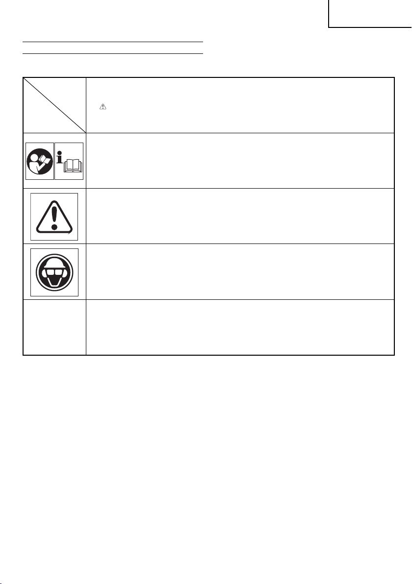
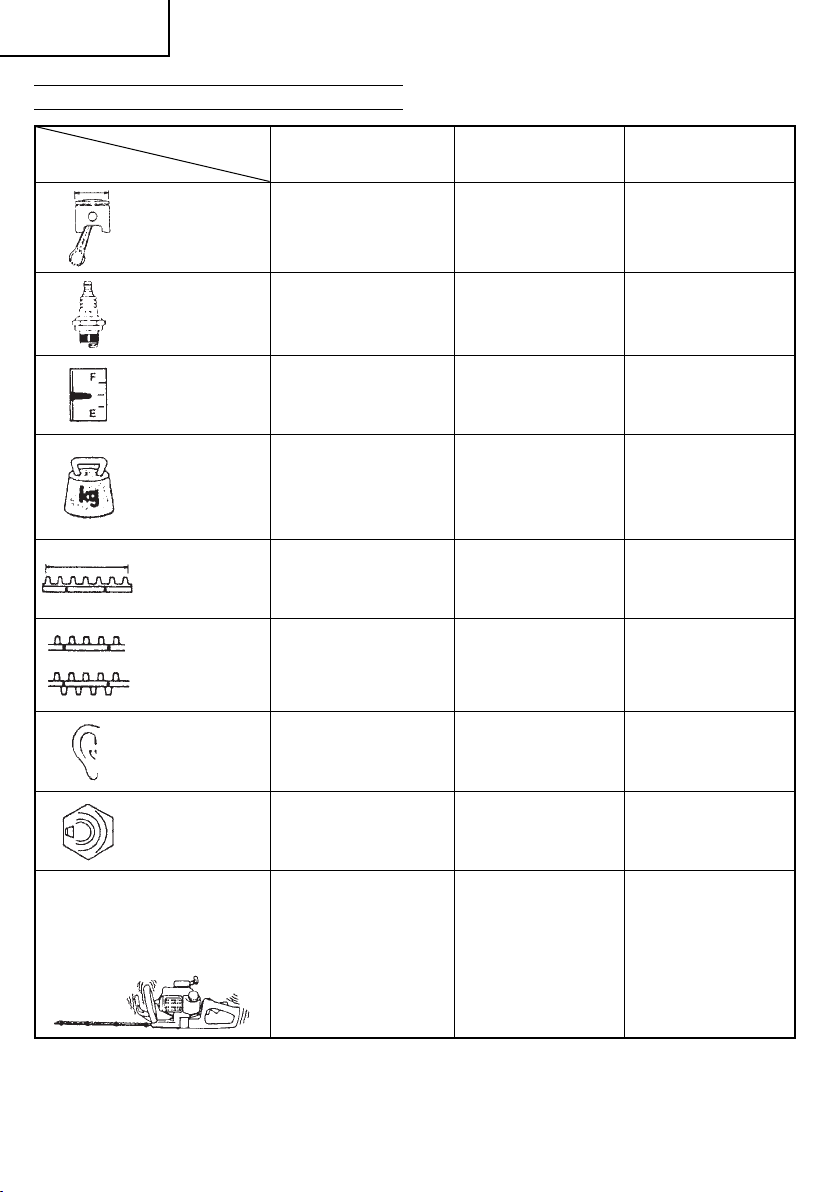
MEANINGS OF SYMBOLS
NOTE: Some units do not carry them.
Symbols
WARNING
The following show symbols used for the machine. Be sure that you understand their meaning before use.
It is important that you read, fully understand and observe the following safety precautions and warnings.
Careless or improper use of the unit may cause serious or fatal injury.
Read, understand and follow all warnings and instructions in this manual and on the unit.
Always wear eye, head and ear protectors when using this unit.
English
Before using your machine
• Read the manual carefully.
• Check that the cutting equipment is correctly assembled and adjusted.
• Start the unit and check the carburetor adjustment. See “MAINTENANCE”.
Contents
WHAT IS WHAT? ...............................................................................6
WARNINGS AND SAFETY INSTRUCTIONS ...................................7
SPECIFICATIONS .............................................................................8
ASSEMBLY
OPERATING PROCEDURES ..........................................................10
MAINTENANCE ...............................................................................10
PROCEDURES ............................................................ 10
5
Page 6
English
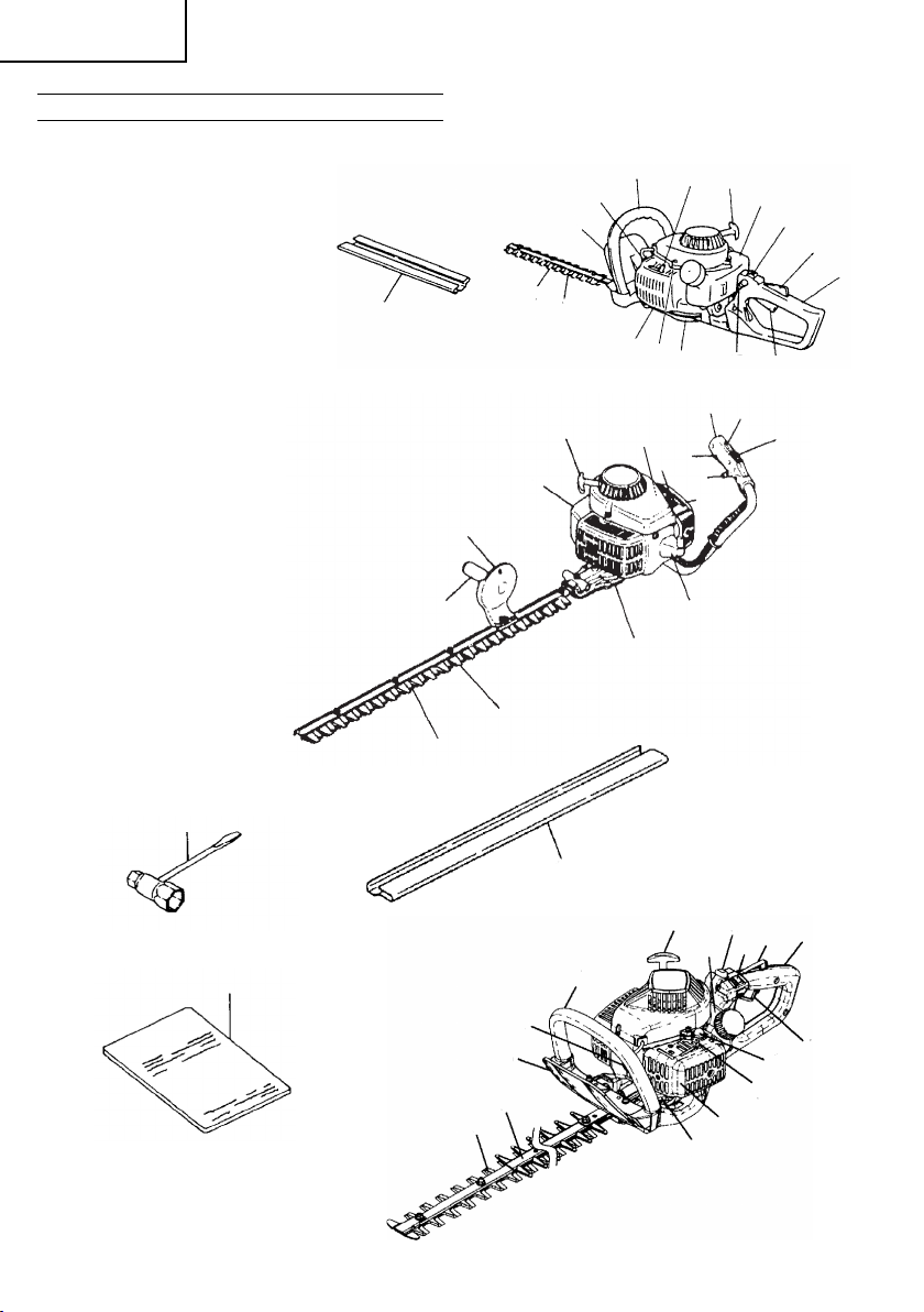
WHAT IS WHAT?
Since this manual covers several models, there may be some
diff erence between these illustrations and your unit. Use the
instructions that apply to your unit.
1. Recoil starter
2. Fuel tank
3. Throttle trigger lookout
4. Throttle trigger
5. Front handle
6. Rear handle
7. Spark plug
guard
8. Hand
9. Cutting blade
10. Air cleaner
11. Ignition switc h
12. Blunt guard
13. Gear case
14. Choke lever
15. Loc k button (opt iona l)
16. Blade cover
17. Lock button
18. Priming pump
19. Combi box spanner
20. Handling instructions
16
5
14
7
8
12
9
10
18
1
2
8
18
14
1
2
11
3
6
13
15
4
CH50EB
6
3
4
15
10
11
5
CH78EB (C), CH78EC (SC)
12
9
19
20
7
8
12
9
CH78EC (C), CH105EC (C)
CH78ED (CP)
16
5
CH66EB (ST)
CH55EB (ST), CH50EA (S T), CH62EA (ST)
CH78EC (ST)
CH66ED (TP), CH78ED (TP)
7
13
1
17
3
11
2
10
13
6
4
18
14
6
Page 7

English
WARNINGS AND SAFETY INSTRUCTIONS
Operator safety
○ Always wear a safety face shield or goggles.
○ Always wear heavy, long pants, boots and gloves. Do not wear
loose clothing, jewelry, short pants, sandals or go barefoot.
Secure hair so it is above shoulder length.
○ Do not operate this tool when you are tired, ill or
infl uence of alcohol, drugs or medication.
○ Never let a child or inexperienced person operate the machine.
○ Wear hearing protection.
○ Never start or run the engine inside a closed room or building.
Breathing exhaust fumes can kill.
○ Keep handles free of oil and fuel.
○ Keep hands
○ Do not grab or hold the unit by the cutting equipment.
○ When the unit is turned off , make sure the cutting attachment
has stopped before the unit is set down.
○ When operation is prolonged, take a break from time to time
so that yo u
(HAVS) which is caused by vibration.
WARNING
○ Antivibration systems do not guarantee that you will not sustain
Hand-Arm Vibration Syndrome or carpal tunnel syndrome.
Therefore, continual and regular users should monitor closely
the condition of their hands and fi ngers. If any sym ptoms of the
above appear, seek medical advice immediately.
○ If you are using any
as a pacemaker, consult your physician as well as the device
manufacturer prior to operating any power equipment.
Unit/machine safety
○ Inspect the entire unit/machine before each use. Replace
damaged part s. Check for fuel leaks and make sure all
fasteners are in place and securely tightened.
Replace parts that are cracked, chipped or damaged in any way
○
before using the unit/machine.
○ Make sure the safety guard is properly attached.
○ Keep others away when making carburetor adjustments.
○ Use only accessories as recommended for this unit/machine by
the manufacturer.
WARNING
Never modify the unit/machine in any way. Do not use your unit/
machine for any job except that for which it is intended.
Fuel safety
○ Mix and pour fuel outdoors and where there are no sparks or
fl ames.
○ Use a container approved for fuel.
○ Do not smoke or
while using the unit/machine.
○ Wipe up all fuel spills before starting engine.
○ Move at least 3 m away from fueling site before starting engine.
○ Stop engine before removing fuel cap.
○ Empty the fuel tank before storing the unit /machine. It is
recommended
left in the tank, store so fuel will not leak.
○ Store unit/machine and fuel in area where fuel vapors cannot
reach sparks or open fl ames from water heaters, electric motors
or switches, furnaces, etc.
WARNING
Fuel is easy to ignite or get explosion or inhale fumes, so that
pay special attention when handling or fi lling fuel.
Cutting safety
○ Do not cut any material other than plant hedge.
○ Inspect the area to be cut before each use. Remove objects
which can be thrown or become
○ For respiratory protection, wear an ae rosol protection mask
when cutting the grass after insecticide is scattered.
○ Keep others including children, animals, bys tanders and
helpers outside the 15 m hazard zo ne. Stop the engine
immediately if you are approached.
away from cutting equipment.
may avoid possible Hand-Arm Vibration Syndrome
medical electric/electronic devices such
allow smoking near fuel or the unit/machine or
that the fuel be emptied after each use. If fuel is
entangled.
under the
○ Hold the unit/machine fi rmly with both hands.
○ Keep fi rm
○ Keep all parts of your body away from the muffl er and cutting
○ Keep cutting tool below shoulder level. NEVER operate unit
○ When relocating to
○ Never place the machine on the ground when running.
○ Always carr y a fi rst-aid kit when operating any power
○ Never start or run the engine inside a closed room
Maintenance safety
○ Maintain the unit/machine according to recommended
○ Disconnect the spark plug before per forming maintenance
○ Keep others away when making carburetor adjustments.
○ Use only genuine Hitachi replacement parts as re commended
Tra ns po rt and storage
○ Carry the unit /machine by hand with the engine stopped and
○ Allow the engine to cool, empt y the fuel tank, and secure the
○ Empty the fuel tank before storing the
○ Store unit/machine out of the reach of children.
○ Clean and maintenance the unit carefully and store it in a dry
○ Make sure engine
○ When transporting in a vehicle or storage, cover blade with
If situations occur which are not covered in this manual, take care
and use common sense. Contact your Hitachi dealer if you need
assistance. Pay special attention to statements preceded by
following words:
WARNING
Indicates a strong possibility of severe personal injury or loss of
CAUTION
Indicates a possibility of personal injur y or equipment damage,
NOTE
Helpful information for correct function and use.
CAUTION
Do not disassemble the recoil starter. You may get a
footing and balance. Do not over-reach.
attachment when the engine is running.
from a ladder, while in a tree or from any unstable support.
machine and ensure that all cutting attachments are stopped.
equipment.
and/or near the infl ammable liquid. Breathing exhaust fumes
can kill.
procedures.
except for carburetor adjustments.
the manufacturer.
by
the muffl er away from your body.
unit/machine before storing or transporting in a vehicle.
recommended that the fuel be emptied after each use. If fuel is
left in the tank, store so fuel will not leak.
place.
blade cover.
life, if instructions are not followed.
if instructions are not followed.
of personal injury with recoil spring.
a new work area, be sure to shut off the
or building
unit/machine. It is
switch is off when transporting or storing.
the
possibility
7
Page 8
English
SPECIFICATIONS
Engine Size (ml) 22 24 22
CH50EB/CH66EB (ST)
MODEL
CH55EB (ST)/CH50EA (ST)
CH62EA (ST)
CH78EC (ST) CH78EB (C)
Spark Plug
Fuel Ta nk Capac ity (l) 0.35 0.35 0.35
Dry Weight (kg)
Overall cutter length
(mm)
:○
Blade type
△
:
Sound pressure level
LpA (dB(A))
(EN 27917)
Sound power level
LwA (dB( A))
(2000/14/EC)
Vibration level (m/s
Front handle
Rear handle
2
) (ISO 7916)
NGK BPM-6A or BPMR-6A
Champion CJ-8Y or RCJ-8Y
CH50EB .......................... 4.1
CH55EB (ST) .................. 4.5
CH66EB (ST) .................. 5.0
CH50EA (ST) .................. 4.3
CH62EA (ST) .................. 4.6
CH50EA (ST)/CH50EB
CH66EB (ST) .................. 650
CH55EB (ST) .................. 550
CH62EA (ST) .................. 620
...... 500
△△
CH50EB ....................... 100.0
CH66EB (ST) .................. 9 2.1
CH55EB (ST) .................. 9 3.6
CH50EA (ST) /CH62EA (ST)
CH66EB (ST) ..................
CH50EB ..........................
CH55EB (ST) ..................
CH50EA (ST) /CH62EA (ST)
CH66EB (ST) ..................
CH50EB ..........................
CH55EB (ST) ..................
CH50EA (ST) /CH62EA (ST)
..... 97.0
104 104 104
4.5
5.3
4.2
.......
5.1/6.5
5.2
11. 5
12.3
.......
11. 3/ 9 . 2
NGK BPM-6A or BPMR-6A
Champion CJ-8Y or RCJ-8Y
5.3 5.2
770 770
91.1 91.4
7.6
6.2
NGK BPM-6A or BPMR-6A
Champion CJ-8Y or RCJ-8Y
○
3.5
5.3
NOTE
Equivalent noise level/vibration level are calculated as the time-weighted energy total fo r noise/vibration levels under var ious working
conditions with the following time distribution : 1/2 idle, 1/2 racing.
* All data is subject to change without notice.
8
Page 9
English
MODEL
Engine Size (ml) 24 24 24
Spark Plug
Fuel Ta nk Capac ity (l)
Dry Weight (kg)
Overall cutter length
(mm)
:○
Blade type
△
:
Sound pressure level
LpA (dB(A))
(EN 27917)
CH78EC (SC)
CH78EC (C)
CH105EC (C)
NGK BPM-6A or BPMR-6A
Champion CJ-8Y or RCJ-8Y
0.35
CH78EC (SC) ........ 5.2
CH78EC (C) ..........5. 2
CH105EC (C) ........5.6
CH78EC (SC) ........ 770
CH78EC (C) ..........770
CH105EC (C) ........1000
○
CH78EC (SC) ........ 93.9
CH78EC (C)
CH105EC (C) ........96.7/96 .7
CH66ED (TP)
CH78ED (TP)
NGK BPM-6A or BPMR-6A
Champion CJ-8Y or RCJ-8Y
0.33 0.33
CH66ED (TP) ...........5.3
CH78ED (TP) ...........5.6
CH66ED (TP) .......... 650
CH78ED (TP) .......... 770
△
98.3 98.3
CH78ED (CP)
NGK BPM-6A or BPMR-6A
Champion CJ-8Y or RCJ-8Y
5.6
770
○
Sound power level
LwA (dB( A))
(2000/14/EC)
2
Front handle
Rear handle
) (ISO 7916)
CH78EC (SC) ........ 4.7
CH78EC (C)
CH105EC (C) ........6.8
CH78EC (SC) ........ 6.4
CH78EC (C)
CH105EC (C) ........5.6
Vibration level (m/s
NOTE
Equivalent noise level/vibration level are calculated as the time-weighted energy total fo r noise/vibration levels under various working
conditions with the following time distribution : 1/2 idle,
* All data is subject to change without notice.
104 104 104
1/2 racing.
CH66ED (TP) ...........8.9
CH78ED (TP) ...........7.8
CH66ED (TP) ...........6.3
CH78ED (TP) ...........5.3
6.1
11.1
9
Page 10

English
ASSEMBLY PROCEDURES
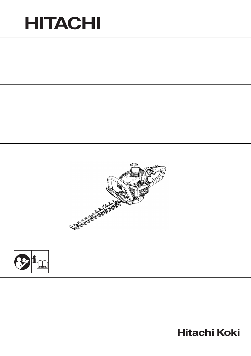
Handle B (3) and Gathering plate (4) (Fig. 1)
1. Remove the four washers and nuts (1) from cutting blade end.
NOTE
In case of Handle B installation only, remove only the nut on the
longest bolt.
2. Set the gathering plate on the cutter guide, then fi nger tighten
the three washers
* Use one each (5) of the two washers, which have been
provided, under the gathering plate or on the two blade-fi xing
bolts from the cutting-blade end to install the gathering plate
on CH105EC (C). (If so equipped)
3. Set the handle B on the longest bolt and
washer and nut.
4. Before securing the fi nger-tightened nuts, screw the blade fi xing
bolts (2) to be seated, then loosen the bolts approx. 1/2 turn.
5. With the bolts set at that position tighten the blade fi xing nuts.
and nuts.
fi nger tighten with the
OPERATING PROCEDURES
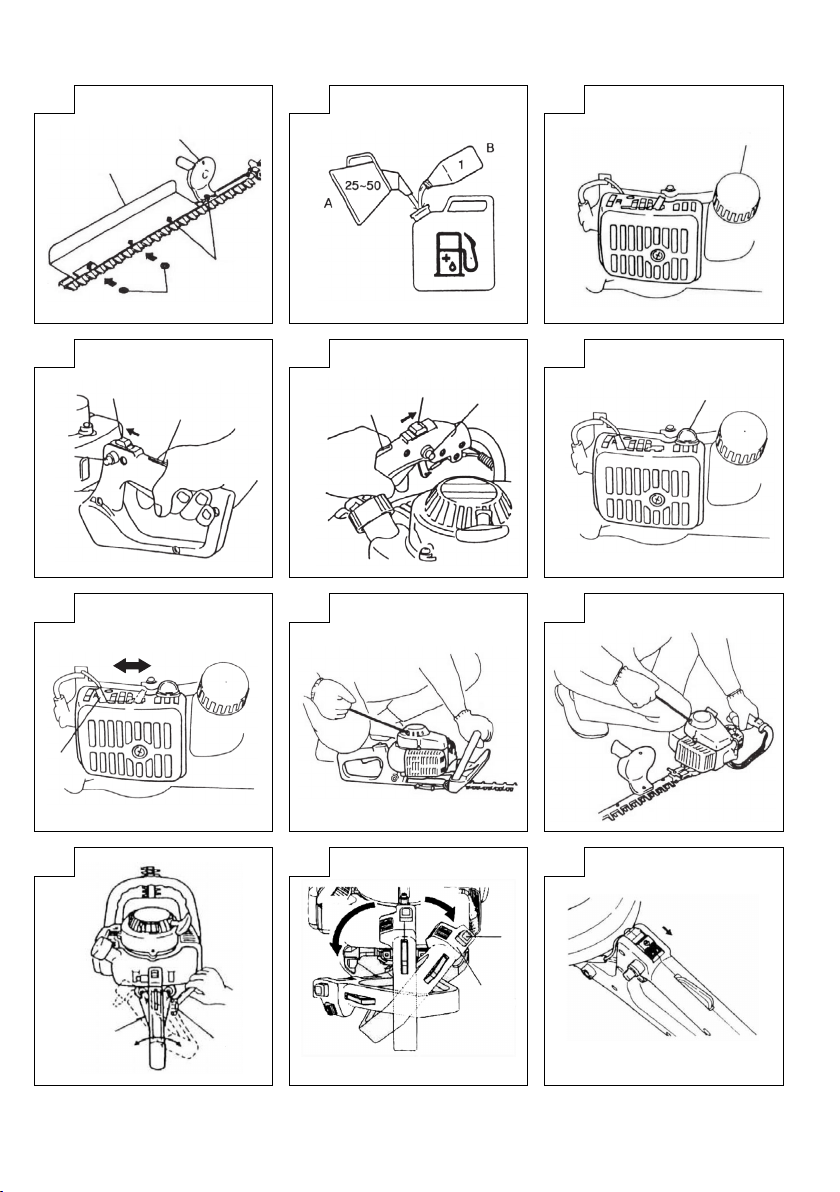
Fuel (Fig. 2)
WARNING
The hedge trimmer is equipped with a two- stroke engine.
Always run the engine on fuel, mixed with oil.
Provide good ventilation, when fueling or handling fuel.
Fuel
○ Always use branded 89 octane unleaded gasoline.
○ Use genuine two-cycle oil or use a mix between 25:1 to 50:1,
please consult
○ If genuine oil is not avail able, use an anti-oxidant added quality
oil expressl y labeled for air-cooled 2-cycle engine use (JASO
FC GRADE OIL or ISO EG C GRADE). Do not use BIA or TCW
(2-str oke water-cooling type) mixed oil.
○ Never use
○ Always mix fuel and oil in a separate clean container.
Always start by fi lling half the amount of fuel, which is to be used.
Then add the whole amount of oil. Mix (sh ake) the fuel mixture. Add
the remaining amount of fuel.
Mix (shak e) the
Fuelin g
WARNING (Fig. 3)
○ Always shut off the engine before refueling.
○ Slowly open the fuel tank (6), when fi lling up with fuel, so that
possible over-pressure disappears.
○ Tighten the fuel cap carefully, after fueling.
○ Always move the unit at least 3 m from the fueling area before
starting.
fueling, clean the tank cap area carefully, to ensure that
Before
no dir t falls into the tank. Make sure that the fuel is well mixed by
shaking the container, before fueling.
Starting
CAUTION
Before starting, make sure the cutting attachment does not
touch anything.
1. Set ignition switch (7) to ON position (A).
* Push priming bulb (10) several times so that fuel fl ows through
the bulb or return pipe. (If so equipped) (Fig. 6)
2. With the safety lever (8) pressed, pull throt tle trigger and push
lock button (9) (If so equipped), then slowly release thrott le the
trigger fi
starting position. (Fig. 4, 5)
3. Set choke lever (11) to CLOSED position (B). (Fig. 7)
the oil bottle for the ratio or Hitachi dealer.
multi-grade oil (10W/3 0) or waste oil.
fuel-mix thoroughly before fi lling the fuel tank.
(Fig. 4, 5)
rst, then the safety lever. This will lock the throttle in
4. Pull recoil st arter briskly, taking care to keep the handle in your
grasp and not allowing it to snap back. (Fig. 8, 9)
5. When you hear the engine at tempts to start, return choke lever
to RUN position (o pen) (C). Then pull recoil starter briskly
again.
NOTE
If engine does
6. After starting engine, allow the engine about 2-3 minutes to
warm up before subjecting it to any load.
Cutting
When cutting, operate engine at full throttle as this maintains proper
cutter speed. When trimming top of hedge, hold trimmer so blades
are between
swing trimmer in an arc toward edge of hedge to sweep cuttings off .
When trimming sides of hedge, hold blade vertic ally and swing unit
in an arc.
NOTE
○ Multi-position twist handle (Fig. 10)
In case your trimmer is
the cutting angle can be adjusted by loosening handle locking
nut (13) . After adjustment has been made, be sure to retighten
the nut.
○ Five positioning twist handle (Fig. 11)
The rear handle can be set in fi ve diff erent positions by pushing
the lock button (14) and turning the rear handle (15).
It is extremely important that the handle is locked in the selected
position.
The lock button will not work while the throttle trigger is being
pulled.
○ The throttle trigger will not work if the rear handle is unlocked.
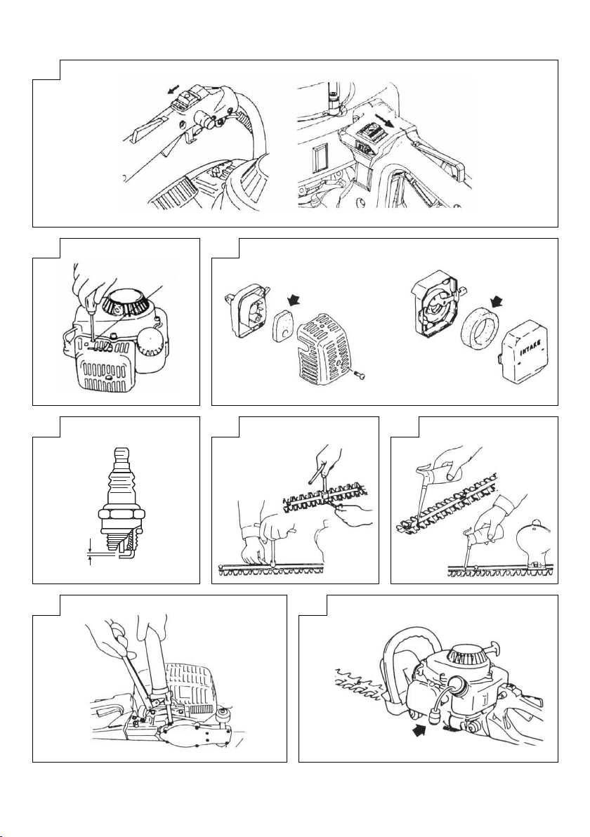
Stopping (Fig.
Decrease engine speed, and push ignition switch to stop position
(F).
not start, repeat procedures from 2 to 4.
15 and 30 degrees from a horizontal position and
twist handle type (12), please note that
12, 13 )
MAINTENANCE
MAINTENANCE, REPLACEMENT OR REPAIR OF THE EMISSION
CONTROL DE VICES AND SYSTEM MAY BE PERFORM ED
BY ANY NONROAD ENGINE REPAIR ESTABLISHMENT OR
INDIVIDUAL.
Carburetor adjustment (Fig. 14)
WARNING
○ The cutting attac hment may be spinning during carburetor
adjustments.
○ Never star t the engine without the complete clutch cover.
Otherwise the clutch can come loose and cause personal
injuries.
In the carburetor, fuel is mixed with air. When the engine is test run
at the fac tory, the carburetor is adjusted.
be required, according to climate and altitude. The carburetor has
one adjustment possibility:
T = Idle speed adjustment screw.
Idle speed adjustment (T)
Check that the air fi lter is clean. When the idle speed is correct, the
cutting attachment will not rotate. If adjustment is required, close
(clo ckwi se) the T-screw, with the engine running, until the cut ting
attachment starts to rotate. Open (co unte r-clo ckwi se) the screw
until the cutting attachment stops. You have reached the correct idle
speed when the engine runs smoothly in all positions well below the
rpm when the cutting attachment starts to rotate.
cutting at tachment still rotates after idle speed adjustment,
If the
contact Hitachi dealer.
A further adjustment may
10
Page 11

English
Air fi lter (Fig. 15)
The air fi lter must be cleaned from dust and dirt in order to avoid:
○ Carburetor malfunctions.
○ Starting problems.
○ Engine power reduction.
○ Unnecessary wear on the engine parts.
○ Abnormal fuel consumption.
Clean the air fi lter daily or more often if working in exceptiona lly
dusty areas.
the air fi lter
Cleaning
Remove the air fi lter cover and the fi lter. Rinse it in warm soap suds.
Check that the fi lter is dr y before reassembly. An air fi lter that has
been used for some time cannot be cleaned completely. Therefore,
it must regularly be replaced by a new one. A
always be replaced.
NOTE
Saturate the element in 2-cycle oil or the equivalent. Squeeze
the element to distribute the oil completely and to remove any
excess oil.
Spark plug (Fig. 16)
The spark plug condition is infl uenced by:
○ An incorrect carburetor setting.
○ Wrong fuel mixture (too much
○ A dirty air fi lter.
○ Hard running conditions (such as cold weather).
These factors cause deposits on the spark plug electrodes, which
may result in malfunction and starting di ffi culties. If the engine
is low on power, diffi cult to start or runs poorly at idling
always check the spark plug fi rst. If the spark plug is dirty, clean it
and check the electrode gap. Readjust if necessary. The correct
gap is 0.6 mm. The spark plug should be replaced after about 100
operation hours or earlier if the electrodes are badly eroded.
NOTE
In some
Cutter blade (Fig. 17, 18)
The blades are installed to the cut ter guide with the four or fi ve
bolts.
can move smoothly.
When clearance is too small
The cutters do not move properly and the sliding surfaces may
seize.
When clearance is too large
The cutters are poor in sharpness.
To adjust the cutter clearance
1. Loosen the cutter fi xing nuts.
2. Fully tighten the cutter fi xing bolts and then loosen them approx.
3. With the bolts set at that position, tighten the cutter fi xing nuts.
Be sure to replace cutter guide fi xing bolts when they are loosened,
worn or damaged. Also be sure to replace damaged cutter blade.
NOTE
Properly
Gear case (Fig. 19)
Apply a good quality lithium based grease through the grease fi tting
until a small amount comes out bet ween the cutter blades and the
gear case.
NOTE
Lubrication should be applied at 50 hour intervals and more
areas, local law requires using a resistor spark plug
to suppress ignition signals. If this machine was originally
equipped with resistor spark plug, use the same type of spark
plug for replacement.
Those bolts are tightened with a clearance so that the cut ters
1/2 turn.
lubricate the cutter sliding surfaces with machine oil.
frequently with heavy
oil in the gasoline).
use.
damaged fi lter must
speed,
Fuel fi lter (Fig. 20)
Remove the fuel fi lter from the fuel tank and thoroughly wash it in
solvent. After that, push the fi lter into the tank completely.
NOTE
If the fi lter is hard due to dust and dirt, replace it.
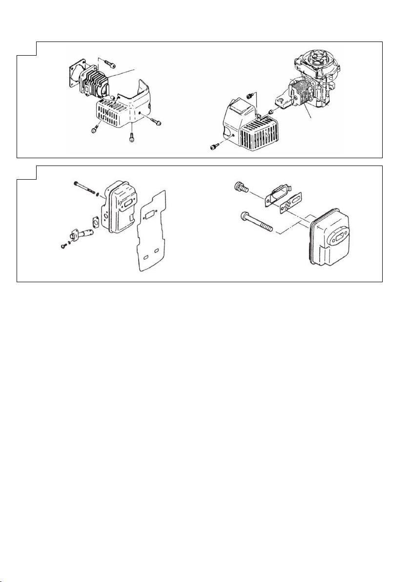
Cleaning the cylinder fi ns (Fig. 21)
When leaves get caught
may overheat , resulting in lower output. To avo id this, always keep
cylinder fi ns and fan case clean.
Every 10 0 operating hours, or once a yea r (more often if conditions
require), clean fi ns and ex ternal surfaces of engine of dust, dirt and
oil deposits which can
Cleaning the muffl er (Fig. 22)
Remove the muffl er and spark arrestor (if so equipped), and clean
out any excess carbon from the exhaust port or muffl er inlet every
100 hours of operation.
For long-term storage
Drain all fuel from the fuel tank. Start
Repair any damage which has resulted from use. Clean the unit with
a clean rag, or high pressure air hose. Put a few drops of two-cycle
engine oil into the cylinder through the spark plug hole, and spin the
engine over several times
it in a dry area.
Maintenance schedule
Below you will fi nd some general maintenance instructions. For
further information please contact your Hitachi dealer.
Daily maintenance
○ Clean the exterior of the hedge trimmer.
○ Check the blade guard for damage or cracks. Change the guard
in case of impacts or cracks.
○ Check that the blade is sharp, and without cracks.
○ Check that the blade nut is suffi ciently tightened.
○ Make sure that the blade transport guard is undamaged and
that it can be securely fi tted.
○ Check that nuts and screws are suffi ciently
Weekl y maintenance
○ Check the starter, especially cord and return spring.
○ Clean the exterior of the spark plug.
○ Remove it and check the electrode gap. Adjus t it to 0.6 mm, or
change the spark plug.
○ Clean the cooling fi ns on the cylinder and check that the air
○ Check gear case is fi lled with grease.
○ Clean the air fi lter.
Monthly maintenance
○ Rinse the fuel tank with gasoline.
○ Clean the exterior of the carburetor and the space around it.
○ Clean the fan and the space around it.
the starter is not clogged.
intake at
between cylinder fi ns (16), the engine
contribute to improper cooling.
and let engine run until it stops.
to distribute oil. Cover the unit and store
tightened.
11
Page 12

Español
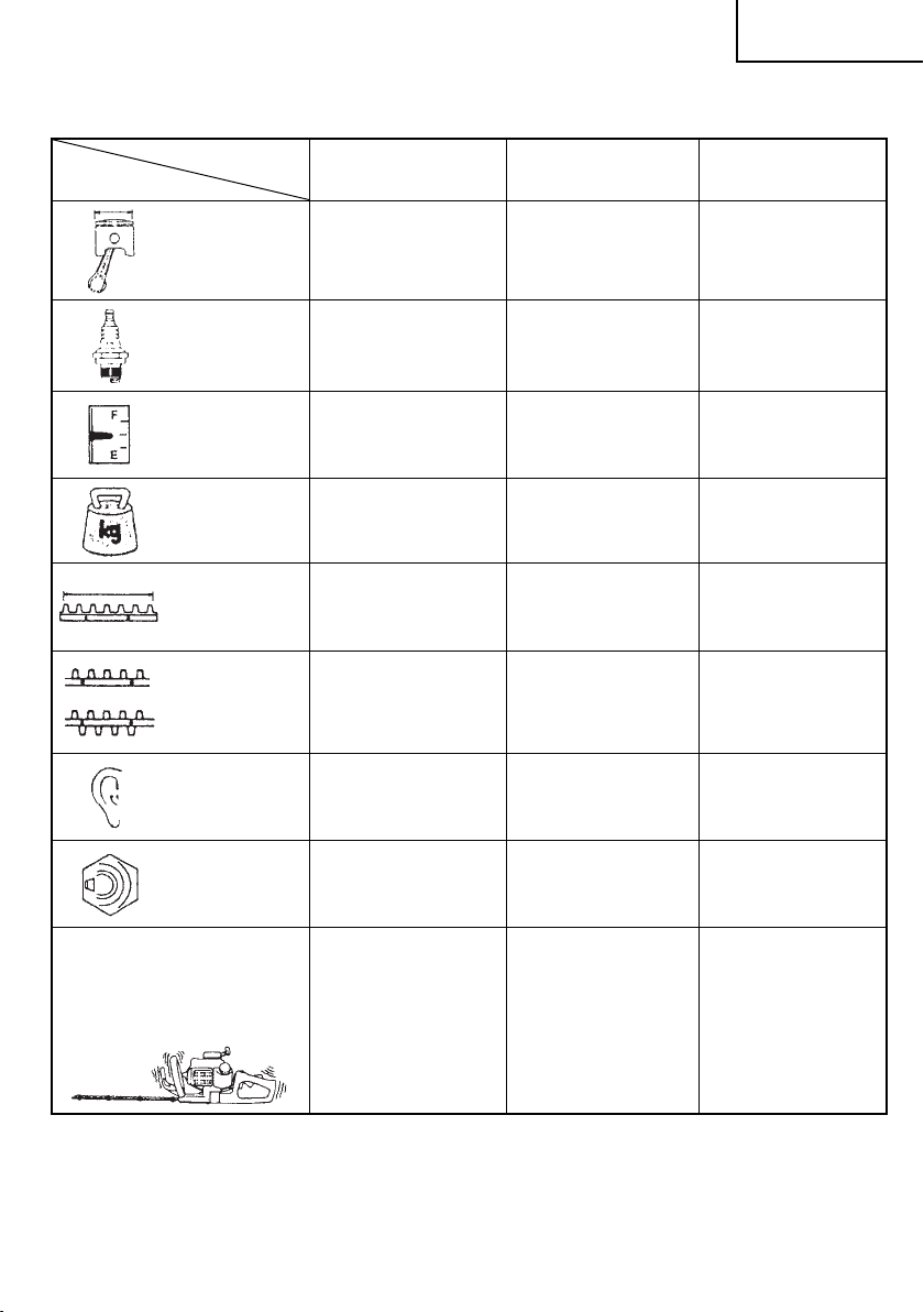
LOS SIGNIFICADOS DE LOS SÍMBOLOS
NOTA: Algunos aparatos no están provistos de ellos.
Símbolos
ATENCIÓN
A continuación se muestran los símbolos usados para la máquina. Asegúrese de comprender su signifi cado
antes del uso.
Es importante que usted lea, entienda totalmente y observe las siguientes precauciones y advertencias de
seguridad. El uso descuidado o incorrecto de la unidad podrá causarle lesiones serias o fatales.
Lea, comprenda y siga todas las advertencias y demás instrucciones de este manual y las que hay en la
máquina.
Utilice siempre las protecciones para los ojos, cabeza y oídos cuando trabaje con la máquina.
Antes de usar la unidad
• Leer cuidadosamente el manual del operador.
• Veri fi car que el equipo de corte esté correctamente montado y ajustado.
• Arrancar la unidad y comprobar el ajuste del carburador. Ver la sección
Contenido
¿QU É ES QUÉ? ...............................................................................13
ADVERTENCIAS E INSTRUCCIONES DE SEGURIDAD ..............14
ESPECIFICACIONES ......................................................................16
PROCEDIMIENTO DE MONTAJE...................................................18
MODO DE USO ...............................................................................18
MANTENIMIENTO ...........................................................................18
de “Mantenimiento”.
12
Page 13

¿QU É ES QUÉ?
Ya que este manual es aplicable a va rios modelos, es posible
que haya diferencias entre las imagenes y su aparato. Utilice las
instruciones que sean relevantes para su unidad.
1. Arrancador retráctil
2. Ta nq ue de combustible
3. Palanca de tope del acelerador
4. Acelerador
5. Manija frontal
Mango posterior
6.
7. Bujía de encendido
8. Protector de mano
9. Cuchilla de corte
10. Filtro de aire
11. Llave de ignición
12. Protec ción redondeada
13. Caj a de engranajes
14. Mando del estrangulador
15. Botón de bloqueo (opc iona l)
16. Cubier ta de la cuchilla
17. Botón de bloqueo
18. Bomba
19. Llave combinada de cubo
20. Instrucciones de manejo
de cebado
16
Español
5
14
7
8
12
9
10
18
1
2
8
18
14
1
2
11
3
6
13
15
4
CH50EB
6
3
4
15
10
11
5
CH78EB (C), CH78EC (SC)
12
9
19
20
7
8
12
9
CH78EC (C), CH105EC (C)
CH78ED (CP)
16
5
CH66EB (ST)
CH55EB (ST), CH50EA (S T), CH62EA (ST)
CH78EC (ST)
CH66ED (TP), CH78ED (TP)
7
13
1
17
3
11
2
10
13
6
4
18
14
13
Page 14

Español
ADVERTENCIAS E INSTRUCCIONES DE
SEGURIDAD
Seguridad del usuario
○ Lleve siempre las protecciones tales como la pantalla o gafas
de seguridad.
○ Use siempre pantalones largos gruesos, botas y guantes. No
utilice prendas sueltas, adorno s, pantalón cor to, sandalias ni
ande descalzo. Sujete el cabello para que quede por encima
de los hombros.
○ No opere esta máquina
la infl uencia del alcohol, drogas o medicamentos.
○ No deje que los niños o personas inexpertas operen esta
máquina.
○ Lleve las protecciones de oídos.
○ Nunca ponga en marcha esta máquina dentro de un local
cerrado o edifi cio. La respiración de los gases
puede causar la muerte.
○ Mantenga la manilla limpia de aceite y combustible.
○ Mantenga las manos alejadas de la cuchilla de corte.
○ No agarre esta unidad por el equipo de corte.
○ Cuando pare la unidad, asegúsere de que el aditamento de
corte se haya detenido antes de apoyarla
○ Durante una operación prolongada, se recomienda interrumpir
de vez en cuando el trabajo para evitar una excesiva exposición
a las vibraciones que podría ocasionar los llamados “dedos
blancos”.
ATE NCI ÓN
○ Los sistemas antivibratorios no garantizan que no sufra el
síndrome de dedos blancos o síndrome de túnel carpiano.
Por lo tanto, los usuarios continuos o regulares deberán
controlar frecuentemente el estado de sus manos y dedos. Si
aparece alguno de los síntomas citados, deberá solicitarse
inmediatamente asistencia médica.
Si usa algún dispositivo médico eléctrico o electrónico tales
○
como marcapasos, consulte a su médico así como al fabricante
del dispositivo antes de operar cualquier equipo de potencia.
Seguridad de la unidad de máquina
○ Inspeccione siempre la unidad de máquina antes de usarla.
Sustituya las piezas dañadas. Compruebe que no haya
de combustible y asegúrese de que todas las piezas estén bien
apretadas en su sitio.
○ Sustituya las piezas agr ietadas, rotas o deterioradas antes de
poner en marcha la unidad de máquina.
○ Asegúrese de que el protector de seguridad esté perfectamente
colocado.
○ Al ajustar el carburador, no permita que
personas.
○ Utilice únicamente los accesorios para esta máquina que hayan
sido recomendados por el fabricante.
ATE NCI ÓN
No deberá modifi carse de ninguna manera la maquina. No usar
su máquina de corte para otra tarea más que para la cual se ha
destinado.
Seguridad sobre el combustible
○ Mezcle y cargue el combustible al aire libre, en lugares donde
no se produzcan chispas ni fuegos.
○ Utilice para
○ No fume ni deje fumar a otras personas en las cercanías del
combustible o de la maquina mientras esta está en marcha.
○ Limpie los residuos de combustible antes de poner en marcha
el motor.
○ Antes de poner en marcha el motor, apártese como mínimo
metros del lugar en el que se ha repostado.
○ Pare el motor antes de quitar el tapón del depósito de
combustible.
○ Antes de guardar la máquina, vacíe el depósito de combustible.
Es conveniente vaciar el depósito cada vez que se ha usado la
máquina. Si se deja combustible
que no puedan producirse fugas.
el combustible un recipiente adecuado.
cuando esté cansado, enfermo o bajo
de escape
sobre el suelo.
fugas
se acerquen otras
en el depósito, asegúrese de
○ Guarde la máquina y el combustible en un lugar donde los
vapores del combustible no puedan entrar en contacto con
chispas o llamas de calentadores de agua, motores eléctricos,
interruptores, hornos, etc.
ATE NCI ÓN
El combustible puede encenderse o explotar fácilmente o ser
inhalados los humos, por lo tanto preste especial atención
cuando maneje o cargue combustible.
Seguridad en el corte
○ No cortar ningún otro material más que plantas.
○ Inspeccione siempre el área que hay que cortar antes de iniciar
el trabajo. Quite
enredarse en el cabezal de corte.
○ Para proteger las vías respiratorias durante el corte de plantas
que hayan sido fumigadas, deberá usarse la máscara de
protección contra aerosoles.
○ Mantenga a otras personas, niños, animales, ayudantes
y personas de alrededor fuera de la
metros. Pare el motor inmediatamente si se acerca alguien.
○ Sujete fi rmemente la máquina con ambas manos.
○ Mantenga estable el cuerpo, con los pies bien apoyados sobre
el suelo. No estire demasiado el cuerpo.
○ Manténga su cuerpo apar tado del silenciador de escape y el
aditamento
○ Mantenga la herramienta de cor te por debajo del hombro.
Nunca trabaje con la unidad desde una escalera, subido a un
árbol o subido a cualquier soporte inestable.
○ Cuando se reubique en una nueva área de trabajo, asegúrese
de parar la máquina y
corte se hayan detenido.
○ Jamás coloque la máquina sobre el suelo cuando esté en
marcha.
○ Lleve siempre un botiquín de primeros auxilios consigo cuando
opere cualquier equipo de potencia.
○ Jamás arranque o haga funcionar el motor dentro de un recinto
o edifìcio cerrado
de los humos de escape puede ser letal.
Seguridad en el mantenimiento
○ Mantenga la unidad de máquina según las recomendaciones.
○ Antes de iniciar el mantenimiento desconecte la bujía, excepto
si hay que ajustar el carburador.
○ No permita que se acerquen otras
ajustando el carburador.
○ Utilice únicamente repuestos y accesorios originales de Hitachi
recomendados por el fabricante.
Tra ns po rt e y almacenamiento
○ Tra ns p or te la unidad de máquina con el motor y el silenciador
apartados del cuerpo.
○ Antes de almacenar o transportar la unidad de máquina en
un vehículo, espere a
depósito de combustible y asegúrela bien.
○ Vací e el depósito antes de guardar la unidad de la máquina. Es
recomendable vaci ar el depósito cada vez que se ha usado la
máquina. Si deja combustible en el depósito, asegúrese de que
no puedan producirse
○ Almacene la unidad de máquina fuera del alcance de los niños.
○ Limpie y mantenga la unidad en perfecto estado, y guárdela en
un lugar seco.
○ Asegúrese de que está desconectado el conmutador del motor
al transportarlo o al almacenarlo.
○ Si se transporta en un vehículo o se almacena,
con una cubierta de cuchilla.
3
Si ocurren situaciones que no se han previsto en este manual,
utilice el sentido común. Contacte con su distribuidor Hitachi
si necesita ayuda. Dedique especial atención a los apartados
precedidos por las palabras siguientes:
ATE NCI ÓN
Indica gran peligro de daños per sonales graves e incluso la
muerte, si no se siguen las instrucciones.
los objetos que puedan salir despedidos o
zona de peligro de 15
de corte mientras está en marcha el motor.
asegure que todos los accesorios de
y/o cerca del líquido infl amable. La inhalación
personas mientras está
que se haya enfriado el motor, vacíe el
fugas.
cubra la cuchilla
14
Page 15

IMPORTANTE
Indica posibilidad de daños personales o materiales, si no se
siguen las instrucciones.
NOTA
Indica información útil para un correcto uso y funcionamiento
de la máquina.
IMPORTANTE
No se desmonte el dispositivo de arranque de retroceso sobre
el aparato. Uno podría herirse a causa del resorte de retroceso.
Español
15
Page 16

Español
ESPECIFICACIONES
MODELO
Tam añ o del motor
(ml)
Bujía
Capacidad
del tanque de
combustible (l)
Peso en vacío (kg)
Largo total de la
cortadora (mm)
:○
Tipo de hoja
:△
CH50EB/CH66EB (ST)
CH55EB (ST)/CH50EA (ST)
CH62EA (ST)
22 24 22
NGK BPM-6A o BPMR-6A
Champion CJ-8Y o RCJ-8Y
0,35 0,35 0, 35
CH50EB .......................... 4,1
CH55EB (ST) .................. 4,5
CH66EB (ST) .................. 5,0
CH50EA (ST) .................. 4,3
CH62EA (ST) .................. 4,6
CH50EA (ST)/CH50EB
CH66EB (ST) .................. 650
CH55EB (ST) .................. 550
CH62EA (ST) .................. 620
...... 500
△△
CH78EC (ST) CH78EB (C)
NGK BPM-6A o BPMR-6A
Champion CJ-8Y o RCJ-8Y
5,3 5,2
770 770
NGK BPM-6A o BPMR-6A
Champion CJ-8Y o RCJ-8Y
○
Nivel de presión de
sonido
LpA (dB(A))
(EN 27917)
Nivel de potencia de
sonido
LwA (dB( A))
(2000/14/EC)
2
Nivel de vibración (m/s
Manija frontal
Manija posterior
NOTA
Los niveles de ruido/vibración equivalentes se calculan como la energía ponderada en tiempo en varia s condiciones de trabajo con la
distribución de tiempo siguiente: 1/2 de ralentí, 1/2 de veloc idad de aceleración al máximo.
* Tod os los datos están sujetos a cambio sin previo aviso.
) (ISO 7916)
CH50EB ....................... 100,0
CH66EB (ST) .................. 9 2,1
CH55EB (ST) .................. 9 3,6
CH50EA (ST) /CH62EA (ST)
CH66EB (ST) ..................
CH50EB ..........................
CH55EB (ST) ..................
CH50EA (ST) /CH62EA (ST)
CH66EB (ST) ..................
CH50EB ..........................
CH55EB (ST) ..................
CH50EA (ST) /CH62EA (ST)
..... 97,0
104 104 104
4,5
5,3
4,2
.......
5,1/6,5
5,2
11, 5
12,3
.......
11, 3/ 9 , 2
91,1 91,4
7,6
6,2
3,5
5,3
16
Page 17

Español
MODELO
Tam añ o del motor
(ml)
Bujía
Capacidad
del tanque de
combustible (l)
Peso en vacío (kg)
Largo total de la
cortadora (mm)
:○
Tipo de hoja
:△
Nivel de presión de
sonido
LpA (dB(A))
(EN 27917)
CH78EC (SC)
CH78EC (C)
CH105EC (C)
24 24 24
NGK BPM-6A o BPMR-6A
Champion CJ-8Y o RCJ-8Y
0,35
CH78EC (SC) ........ 5,2
CH78EC (C) ..........5, 2
CH105EC (C) ........5,6
CH78EC (SC) ........ 770
CH78EC (C) ..........770
CH105EC (C) ........1000
○
CH78EC (SC) ........ 93,9
CH78EC (C)
CH105EC (C) ........96,7/96 ,7
CH66ED (TP)
CH78ED (TP)
NGK BPM-6A o BPMR-6A
Champion CJ-8Y o RCJ-8Y
0,33 0,33
CH66ED (TP) ...........5,3
CH78ED (TP) ...........5,6
CH66ED (TP) .......... 650
CH78ED (TP) .......... 770
△
98,3 98,3
CH78ED (CP)
NGK BPM-6A o BPMR-6A
Champion CJ-8Y o RCJ-8Y
5,6
770
○
Nivel de potencia de
sonido
LwA (dB( A))
(2000/14/EC)
2
Nivel de vibración (m/s
Manija frontal
Manija posterior
NOTA
Los niveles de ruido/vibración equivalentes se calculan como la energía ponderada en tiempo en varia s condiciones de trabajo con la
distribución de tiempo siguiente: 1/2 de
* Tod os los datos están sujetos a cambio sin previo aviso.
) (ISO 7916)
CH78EC (SC) ........ 4,7
CH78EC (C)
CH105EC (C) ........6,8
CH78EC (SC) ........ 6,4
CH78EC (C)
CH105EC (C) ........5,6
ralentí, 1/2 de velocidad de aceleración al máximo.
104 104 104
CH66ED (TP) ...........8,9
CH78ED (TP) ...........7,8
CH66ED (TP) ...........6,3
CH78ED (TP) ...........5,3
6,1
11,1
17
Page 18

Español
PROCEDIMIENTO DE MONTAJE
Manija B (3) y placa de recogida (4) (Fig. 1)
1. Desmontar las cuatro arandelas y tuercas (1) del extr emo de la
cuchilla de corte.
NOTA
En el caso de la instalación de la manija B solamente,
desmontar sólo la tuerca del tornillo más largo.
2. Instalar la placa de recogida sobre
apretar con los dedos las tres arandelas y tuercas.
* Se necesitan dos arandelas especiales (5) de cada una
por debajo de la placa de recogida o sobre los dos tornillos
fi jadores para instalar la placa de recogida sobre el CH105EC
tiene equipado)
(C). (Si lo
3. Colocar la manija B en el tornillo más largo y ajustar con los
dedos la arandela y la tuerca.
4. Antes de apretar las tuercas ajustadas con los dedos, enroscar
los tornillos de fi jación (2) de la cuchilla para que queden bien
sujetos, luego afl ojar aprox, 1/2 vuelta
5. Con los tornillos colocados en esa posición, ajustar las tuercas
de fi jación de la cuchilla.
la bar ra de guía luego
los tornillos.
MODO DE USO
Combustible (Fig. 2)
ATE NCI ÓN
El motor es de dos tiempos y ha de funcionar siempre con una
mezcla de gasolina y aceite.
Asegurarse siempre de que hay buena ve ntilación en los
lugares donde se maneja el combustible.
Gasolina
○ Utilice siempre gasolina sin plomo de marca de 89 de octanos.
○ Use ac eite de dos
a 50:1, sírvase ver la relación en la botella o consulte con un
distribuidor Hitachi.
○ Si no dispone de aceite original, use un aceite con antioxidante
de calidad que esté etiquetad o expr esamente para motores de
dos tiempos enfriados por aire (JASO FC
EGC GRADE). No utilice aceite mezclado BIA o TCW (t ipo de 2
tiempos refrigerado por agua).
○ No utilice nunca aceites multigrado (10W/30 ) ni residuales.
○ Mezcle siempre la gasolina y el aceite en un recipiente especial
para ello que esté limpio.
Empiece llenando el rec ipiente hasta la
añada luego todo el aceite. Sacuda la mezcla y añada el resto de
la gasolina.
Antes de llenar el depósito agite la mezcla cuidadosamente.
Repostar
ATE NCI ÓN (Fig. 3)
○ Parar siempre el motor antes de repostar.
○ Para llenar el combustible del tanque, deberá abrirse
lentamente la tapa del tanque de combustible (6) para que
escape la sobrepresión que pueda contener.
○ Después de haber repostado, apretar bien la tapa.
○ Antes de arrancar la unidad,
del área de carga de combustible.
Antes de repostar, limpiar cuidadosamente el área del tapón del
tanque, para garantizar que no entra suciedad en el depósito.
Asegurarse de que el combustible está bien mezclado agitando
bien el recipiente antes de verter su contenido en
Arranque
IMPORTANTE
Antes del arranque, asegúrense de que el aditamento de cor te
no esté rozado con nada.
18
tiempos original o use una mezcla de 25:1
GRADE OIL o ISO
mitad con gasolina y
deberá alejarse por lo menos 3 m
el depósito.
1. Coloque el interruptor de encendido (7) en la posición ON
(con ecta do) (A). (Fig. 4, 5)
* Presione va rias veces el cebador (10) , de manera que el
combustible fl uya a través del cebador o de la tubería de
retorno (Si lo tiene equipado). (Fig. 6)
2. Con la palanca
palanquita del acelerador y empujar el botón de bloqueo (9) (Si
lo tiene equipado), soltar después lentamente el acelerador. Se
cerrará así la mariposa en la posición de arranque. (Fig. 4, 5)
3. Coloque la palanca del estár ter (11) en la posición CLOSED
(cer rado) (B). (Fig. 7)
4. Tirar enérgicamente del arrancador de retroceso y teniendo
cuidado de no soltar el mango. (Fig. 8, 9)
5. Cuando escuche que el motor intenta arrancar, vuelva la
palanca del estárter a la posición RUN (abi erto) (C). Entones
tire de nuevo el arrancador de retroceso
NOTA
Si el motor no se pone en marcha, repita los puntos 2 al 4.
6. Después de arrancar el motor, pemita que el motor se caliente
unos 2-3 minutos antes de someter a cualquier carga.
Corte
Al efectuar el corte, operar el motor con el acelerador a fondo para
la velocidad apropiada de corte.
mantener
Cuando se recor te la parte superior de un seto, mantener la
recortadora de manera que las cuchillas for men un ángulo de 15
y 30 grados con la horizontal y oscilar la recortadora en forma de
arco contra el borde del seto para eliminar los recortes.
se recorten los costados de un seto, mantener
Cuando
vertica lmente la cuchilla y mover la unidad en forma de arco.
NOTA
○ Empuñadura con eje de torsión multi-posición (Fig. 10)
En caso de que su desbrozadora sea de tipo empuñadura
con eje de torsión (12), el ángulo de cortado puede ajustarse
afl ojando la tuerca de bloqueo de la empuñadura (13) . Una vez
realizado el ajuste, asegúrese de volver a apretar la tuerca.
○ Empuñadura con eje de torsión de cinco posiciones (Fig.
11)
La empuñadura trasera puede ajustarse en cinco posiciones
diferentes presionando el botón de bloqueo (14) y girando la
empuñadura trasera (15).
Es muy importante bloquear la empuñadura en la posición
seleccionada.
El botón de bloqueo no funcionará cuando se tire de la
esbrozadora reguladora.
○ La esbrozadora reguladora no funcionará si se desbloquea la
empuñadura posterior.
Parada (Fig. 12, 13 )
Reduzca la velocida d del motor y empuje el interruptor
encendido a la posición de stop (F).
de seguridad (8) presionada, tirar de la
com fuerza.
de
MANTENIMIENTO
EL MANTENIMIENTO, REEM PLAZO O REPARACIÓN DE LO S
DISPOSITIVOS Y SISTEMAS DE CONTROL DE GAS PUEDEN
HACERSE EN CUALQUIER TALLER DE REPARACIÓN DE MOTOR
NO PARA CARRERAS O PERSONALMENTE.
Ajuste del carburador (Fig. 14)
ATE NCI ÓN
○ Es posible que el accesorio de corte dé vueltas durante los
ajustes del carburador.
○ Jamás deberá arrancarse el motor sin la cubierta completa
del embrague, ya que podría afl ojarse el embrague y causar
lesiones personales.
En el carburador se mezcla el combustible con el aire. Durante
prueba del motor en la fábrica , el carburador está ajustado.
la
Sin embargo, puede ser necesario reajustarlo según el clima y la
altitud. El carburador tiene una posibilidad de ajuste:
T = Tornillo para el ajuste de las revoluciones de ralentí.
Page 19

Español
Ajuste de precisión de ralentí (T)
Comprueben que el fi ltro de aire esté limpio. Cuando la velocidad
de ralentí es correcta, el aditamento de corte no ha de girar. Si
necesita ajustarlo, cierre (hacia la derecha) el tornillo T con el motor
en marcha hasta que el aditamento de corte empiece
(hacia la izquierda) el tornillo T hasta que la cuchilla se detenga. Se
habrá alcanzado el ralentí correcto cuando el motor funcione con
regularidad en cualquier posición por debajo de las revoluciones
por minuto en las que empieza a girar el aditamento de corte.
Si la cuchilla
ralentí, comuníquese con un distribuidor Hitachi.
Filtro de aire (Fig. 15)
Este fi ltro debe limpiarse con regularidad quitando polvo y suciedad
a fi n de evitar:
○ Perturb aciones en el funcionamiento del carburador.
○ Problemas de arranque.
○ Pérdidas de potencia.
○ Desgaste innecesario de
○ Consumo de combustible excesivo.
Limpie el fi ltro de aire diariamente; si las condiciones de trabajo son
desfavorables.
Limpieza del fi ltro de aire
Desmontar la cubier ta del fi ltro y sacarlo. Limpiar el fi ltro con agua
jabonosa caliente. Antes de volver a montarlo, comprobar que
está seco. Un fi ltro
podrá quedar completamente limpio, por lo que los fi ltros deberán
sustituirse por otros nuevos a intervalos regulares. Cambie siempre
los fi ltros que estén dañados.
NOTA
Bañe el elemento en aceite de 2 ciclos o equivalente.
Bujía (Fig. 16)
El estado de la bujía depende de lo siguiente:
○ Carburador mal ajustado.
○ Mezcla incorrecta de combustible y aceite (exceso de aceite).
○ Filtro de aire sucio.
○ Condiciones de funcionamiento difíciles (co mo clima frío).
Tod os estos factores dan lugar a la
electrodos pudiendo causar per turbaciones en el funcionamiento
y difi cultades de arranque. Si en la cortadora se nota falta de
potencia, si los arranques son difíciles y si el ralentí es inestable,
controlar siempre primero la bujía antes de adoptar otras medidas.
Si la bujía está
electrodos, que ha de ser de 0,6 mm. La bujía debe cambiarse
después de unas 10 0 horas de funcionamiento o antes si los
electrodos están muy gastados.
NOTA
En algunas áreas, los reglamentos locales requieren el uso de
Hoja de la cortadora (Fig. 17, 18)
Las cuchillas van instaladas en la guía de la
o cinco tornillos apretados con una holgura que permite el libre
movimiento de las mismas.
Cuando la holgura es muy pequeña
Las cuchillas no pueden moverse correctamente, y podrían
agarrotarse las superfi cies deslizantes.
Cuando la holgura es excesiva
Las cuchillas no cortan efi cazmente.
todavía gira después del ajuste de la velocidad al
las piezas del motor.
de aire que ha prestado largo servicio nunca
Comprima el elemento para distribuir el aceite completamente
y para retirar cualquier exceso de aceite.
formación de sedimentos en los
muy sucia, limpiarla y controlar la separación entre
una bujía de encendido de
de ignición. En el caso de que esta máquina esté equipada
originalmente de la bujía de encendido de resistencia, debe
usar algún tipo de bujía de encendido de resistencia como
repuesto.
resistencia para eliminar señales
a girar. Abra
barra mediante cuatro
Para ajustar la holgura de
1. Afl oje las tuercas que las sujetan a la guía.
2. Apriete por completo los tornillos de sujeción de las cuchillas, y
luego afl ójelos aproximadamente 1/2 vuelta.
3. Con los tornillos en esta posición, apriete las tuercas de
sujeción de las cuchillas.
Asegúrese de cambiar los tornillos de
cortasetos cuando compruebe que están fl ojos, gastados o
dañados. Tam bi é n asegúrese de cambiar la cuchilla del cortasetos
dañada.
NOTA
Lubrique correctamente las superfi cies deslizantes del
cortasetos con aceite.
Caja de engranajes (Fig. 19)
Aplíquese grasa a base de litio de buena calidad a través de
grasera hasta que una cantidad pequeña aparezca entre las hojas
cortantes y la caja de engranajes.
NOTA
Hay que efectuar la lubricación a intervalos de 50 horas o con
más frecuencia en caso de trabajo intenso.
Filtro de combustible (Fig. 20)
Quitar el fi ltro de combustible del tanque de combustible y
totalmente con disolvente. Posteriormente, vuelva a insertar
totalmente el fi ltro en el tanque.
NOTA
Si el fi ltro estuviera obstr uido debido al polvo y la suciedad,
deberá reemplazarse.
Limpieza de las aletas del cilindro (Fig. 21)
El aprisionamiento de las hojas entre las aletas de cilindro
(16) puede ocasionar el sobrecalentamiento
consiguiente pérdida de potencia. Par a evitar esto, mantenga
siempre separadas las aletas y el ventilad or.
Cada 10 0 horas de operación, o una vez al año (o con más
frecuencia cuando sea necesario), limpiar las aletas y la superfi cie
exterio r del motor, para eliminar los sedimentos de
y aceite que causen el enfriamiento inadecuado.
Limpieza del silenciador (Fig. 22)
Desmontar el silenciador y parachispas (si lo tiene equipado), y
limpiar cualquier exceso de carbón de la boca de escape o entrada
del silenciador cada 100 horas de operación.
Para el almacenamiento durante largos periodos
Drenar totalmente el
el motor y dejarlo en funcionamiento hasta que se pare. Reparar
cualquier daño que haya sufrido por el uso. Limpiar la unidad con
trapo limpio o soplar con la manguera de aire de alta presión.
Aplicar algunas gotas de aceite de motor para motocicletas dentro
del cilindro a través del orifi cio de la bujía de encendido y girar el
motor varias veces para que se distribuya el aceite. Cubrir la unidad
y almacenar en un lugar seco.
Esquema de mantenimiento
A continuación se muestran algunas instrucciones generales de
mantenimiento. Para obtener información adicional, contacte con
su distribuidor Hitachi.
Cuidados diarios
○ Limpie la máquina por fuera.
○ Compruebe la protección de la hoja que no esté deteriorada ni
tenga grietas.
○ Cambie la protección si ha estado expue sta a golpes o tiene
grietas. Compruebe que la hoja esté afi lada y no tenga grietas.
○ Compruebe que esté
○ Compruebe que esté entera la protección de transpor te de la
hoja y que pueda sujetarse bien.
○ Compruebe que las tuercas y tornillos estén apretados.
las cuchillas
sujeción de la guía del
del motor, con la
polvo, suciedad
contenido del tanque de combustible. Arrancar
bien apretada la tuerca de la hoja.
la
lavar
19
Page 20

Español
Cuidados semanales
○ Compruebe el aparato de arranque, la cuerda y el muelle de
recuperación.
○ Limpie la bujía por fuera.
○ Desmóntela y compruebe que la distancia entre los electrodos
sea de 0,6 mm, o cambie la bujía.
○ Limpie las aletas de refrigeración del cilindro y controle que no
ha obstruido la admisión de aire.
se
○ Compruebe que la caja de cambios esté bien engrasada.
○ Limpie el fi ltro de aire.
Cuidados mensuales
○ Limpie el depósito de combustible con gasolina.
○ Limpie el carburador por fuera y los alrededores del mismo.
○ Limpie el ventilador y sus alrededores.
20
Page 21

SIGNIFICADO DOS SÍMBOLOS
NOTA: Os símbolos referidos não se encontram em todos os
modelos.
Símbolos
ADVERTÊNCIA
A seguir aparecem os símbolos utilizados pela máquina. Assimile bem seus signifi cados antes do uso.
É importante que você leia, compreenda integralmente e observe as seguintes precauções e advertências
de segurança. O uso descuidado ou incorreto do aparelho pode causar lesões graves ou até fatais.
Leia, compreenda e siga todas as advertências e instruções contidas neste manual e no aparelho.
Sempre use protetores para os olhos, cabeça e ouvidos durante o uso deste aparelho.
Português
Antes de usar a ferramenta
• Leia o manual atentamente.
• Veri fi que se o equipamento de corte está montado e ajustado corretamente.
• Ligue a ferramenta e veri fi que o ajuste do carburador. Consulte “MANUTENÇÃO”.
Sumário
DESCRIÇÃO DE CADA
ADVERTÊNCIAS E INSTRUÇÕES DE SEGURANÇA ...................23
ESPECIFICAÇÕES ..........................................................................24
PROCEDIMENTOS DE MONTAGEM .............................................2 6
PROCEDIMENTOS DE OPER AÇÃO ..............................................2 6
MANUTENÇÃO ...............................................................................26
COMPONENTE ........................................2 2
21
Page 22

Português
DESCRIÇÃO DE CADA COMPONENTE
Como este manual cobre vários modelos, podem exi stir algumas
diferenças entre as ilustrações e a sua fer ramenta. Use as
instruções que se aplicam à sua ferrame nta.
1. Acionador de arranque de recuo
2. Ta nq ue de combustível
3. Visor do gatilho do acelerador
4. Gatilho do acelerador
5. Cabo frontal
traseiro
6. Cabo
7. Vela de ignição
8. Protetor da mão
9. Lâmina de corte
10. Filtro de ar
11. Interr uptor de ignição
12. Pe nte de proteção
13. Cai xa de engrenagens
14. Alavanca do afogador
15. Botão de bloqueio (opc iona l)
16. Cober tura protetora da lâmina
17. Botão de bloqueio
18. Bomba de escorva
19. Chave combinada
20. Instruções
de manipulação
16
5
14
7
8
12
9
10
18
1
2
8
18
14
1
2
11
3
6
13
15
4
CH50EB
6
3
4
15
10
11
5
CH78EB (C), CH78EC (SC)
12
9
19
20
7
8
12
9
CH78EC (C), CH105EC (C)
CH78ED (CP)
16
5
CH66EB (ST)
CH55EB (ST), CH50EA (S T), CH62EA (ST)
CH78EC (ST)
CH66ED (TP), CH78ED (TP)
7
13
1
17
3
11
2
10
13
6
4
18
14
22
Page 23

Português
ADVERTÊNCIAS E INSTRUÇÕES DE
SEGURANÇA
Segurança do operador
○ Sempre use uma máscara ou óculos de proteção.
○ Sempre use calças pesadas e compridas, botas e luvas. Não
use roupas folgad as, jóias e bijuteria, calções, sandálias e
nunca trabalhe descalço. Prenda o cabelo para que ele não
caia por cima dos ombros.
○ Não use esta fer ramenta
sob efeitos de álcool, drogas ou medicamentos.
○ Nunca deixe uma criança ou uma pessoa inexperiente operar
esta ferramenta.
○ Use uma proteção para os ouvidos.
○ Nunca arranque nem deixe o motor funcionando no interior de
um quarto ou prédio. A inalação dos gases de escape
provocar a morte.
○ Mantenha os cabos livres de óleo e gasolina.
○ Mantenha as mãos afastadas do mecanismo de corte.
○ Não agarre nem segure a ferramenta pelo mecanismo de corte.
○ Depois de desligar a ferramenta , certifi que-se de que o
mecanismo de corte tenha parado antes de deixá-la em
lugar.
○ Durante trabalhos prolongados, faça pausas de vez em quando
para prevenir a síndrome de vibração das mãos e braços
(HAVS) causada pela vibração.
ADVERTÊNCIA
○ Sistemas anti-vibratórios não garantem que o operador não
sofra da síndrome de vibração das mãos e braços ou da
síndrome do túnel carpal. Portan to, os usuários freqüentes
e contínuos devem estar sempre atentos ao estado das suas
mãos e dedos. Se você perceber qualquer um dos sintomas
mencionados acima,
○ Se você estiver usando um dispositivo médico elétrico/
eletrônico como, por exemplo, um marcapasso, consulte o
seu médico e o fabricante do aparelho antes de trabalhar com
equipamentos motorizados.
Segurança da ferramenta
○ Inspecione toda a ferramen ta antes de cada uso. Substitua
as peças danifi cadas. Ver ifi
combustível e certifi que-se de que todos os parafusos e porcas
estejam instalados e apertados corretamente.
○ Substitua todas as peças que estiverem rachadas, lascadas ou
danifi cadas antes de usar esta ferrament a.
○ Certifi que-se de que o protetor de segurança esteja instalado
corretamente.
○ Mantenha
carburador.
○ Use somente os acessóri os rec omendados pelo fabric ante
para esta ferramenta.
ADVERTÊNCIA
Nunca modifi que a ferra menta de qualquer maneira. Não use a
ferramenta para qualquer outra fi nalidade que não tenha sido
concebida para a mesma.
Segurança do combustível
○ Misture e abasteça o combustível ao ar livre e num local onde
não haja faíscas ou chamas.
○ Use um recipiente aprovado para
○ Não fume e proíba o fumo nas proximidades do combustível
ou da fer ramenta e, acima de tudo, durante o trabalho com a
ferramenta .
○ Limpe qualquer combustível derramado antes de arrancar o
motor.
○ Afaste-se pelo menos 3 m do local de abastecimento antes de
arrancar o motor.
○ Apague
combustível.
○ Esvazie o tanque de combustível antes de guardar a
ferramenta . É recomendável esvaziar o tanque de combustível
após cada uso. Se tiver que deixar o combustível no tanque,
guarde a ferram enta de forma que não haja vaz amento de
combustível.
○
Guarde a ferramenta num local onde os vapores do combustível
não possam entrar em contato com faíscas ou chamas aber tas
de aquecedores de água, motores ou interruptores elétricos,
fornos, etc.
outras pessoas afastada s ao fazer ajustes no
o motor antes de retirar a tampa do tanque de
quando estiver cansado, doente ou
pode
algum
consulte um médico imediatamente.
que se ex istem vazame ntos de
combustível.
ADVERTÊNCIA
O combustível é facilmente infl amável e altamente explosivo,
bem como pode provocar a inalação de fumos e, portanto,
tome muito cuidado ao manipular ou abastecer o combustível.
Segurança durante o corte
○ Não corte nenhum material que não seja sebe viva.
○ Inspecione a área a ser cortada antes de
coisas que possam ser lançadas ou fi car emaranhadas.
○ Para a proteção das vias respiratórias após uma aplicação de
inseticidas, use uma máscara de proteção contra aerossóis.
○ Mantenha outras pessoas, incluindo crianças, animais,
curiosos ou ajudantes fora da zona de perigo de 15 metros.
Apague o motor
○ Segure fi rmemente a ferramenta com ambas as mãos.
○ Mantenha o equilíbrio e olhe onde anda. Não exceda o seu raio
de alcance.
○ Quando o motor estiver em funcionamento, mantenha todas as
partes do corpo afastadas do silenciador e do mecanismo de
corte.
○ Mantenha o
NUNCA opere a ferramenta enquanto estiver em uma escada,
em uma árvore ou em qualquer apoio instável.
○ Quando se deslocar para outra área de trabalho, apague o
motor e certifi que- se de que o mecanismo de corte esteja
parado.
○ Nunca coloque
○ Sempre tenha um estojo de primeiros socorros per to quando
trabalhar com equipamentos motorizados.
○ Nunca arranque nem deixe o motor funcionando em locais
fechados e/ou nas proximidades de líquidos infl amáveis. A
inalação dos gases de escape pode provocar a morte.
Segurança durante a manutenção
○
Faça a manutenção da ferrament a de acordo com os
procedimentos recomendados.
○ Desconecte a vela de ignição antes de iniciar a manutenção,
exceto se tiver que fazer ajustes no carburador.
○ Mantenha outras pessoas afastadas ao fazer ajustes no
carburador.
○ Use somente peças sobressalentes genuínas da Hitachi, tal
como recomendado pelo
Tra ns po rt e e armazenamento
○ Tra ns p or te a ferramenta com as mãos, com o motor parado e
com o silenciador afastado do corpo.
○ Deixe o motor se esfriar, esvazie o tanque de combustível,
e segure a fer ramenta fi rmemente antes de guardá-la ou
transportá-la num veículo.
○ Esvazie o tanque de combustível antes
ferramenta . É recomendável esvaziar o tanque de combustível
após cada uso. Se tiver que deixar o combustível no tanque,
guarde a ferram enta de forma que não haja vaz amento de
combustível.
○ Guarde a ferramenta fora do alcance das crianças.
○ Limpe a ferramenta e realize a sua manutenção
cuidadosamente
○ Certifi que-se de que o interruptor de ignição esteja desligado
quando transportar ou guardar a ferramenta.
○ Para transportar ou guardar a ferramenta num veículo, cubra a
lâmina com a sua cobertura protetora.
Se ocorrer algo que não estiver coberto neste manual, seja
cauteloso e
Hitachi quando precisar de assistência técnica. Preste especial
atenção aos textos precedidos pelos seguintes termos:
ADVERTÊNCIA
Indica uma forte possibilidade de sofrer ferimentos pessoais ou
de perder a vida, se as instruções não forem observadas.
PRECAUÇÃO
Indica uma possibilidade de ferim entos pessoais ou danos
materiais, se as instruções não forem observadas.
NOTA
Informações úteis sobre o funcionamento e uso correto.
PRECAUÇÃO
Não desmonte o acionador de arranque
sofrer ferimentos pessoais com a mola de recuo.
imediatamente se alguém se aproximar.
mecanismo de corte abaixo do nível da cintura.
a ferramenta em funcionamento no solo.
fabricante.
antes de guardá-la num local seco.
atue com o senso comum. Contate o seu revendedor
cada uso. Retire
de guardar a
de recuo. Você pode
23
Page 24

Português
ESPECIFICAÇÕES
MODELO
Cilindrada (ml) 22 24 22
Vela de ignição
Capacidade
do tanque de
combustível (l)
Peso a seco (kg)
Comprimento total do
cortador (mm)
:○
Tipo de lâmina
△
:
CH50EB/CH66EB (ST)
CH55EB (ST) CH50EA (ST)
CH62EA (ST)
NGK BPM-6A ou BPMR-6A
Champion CJ-8Y ou RCJ-8Y
0,35 0,35 0, 35
CH50EB .......................... 4,1
CH55EB (ST) .................. 4,5
CH66EB (ST) .................. 5,0
CH50EA (ST) .................. 4,3
CH62EA (ST) .................. 4,6
CH50EA (ST)/CH50EB
CH66EB (ST) .................. 650
CH55EB (ST) .................. 550
CH62EA (ST) .................. 620
...... 500
△△
CH78EC (ST) CH78EB (C)
NGK BPM-6A ou BPMR-6A
Champion CJ-8Y ou RCJ-8Y
5,3 5,2
770 770
NGK BPM-6A ou BPMR-6A
Champion CJ-8Y ou RCJ-8Y
○
Nível de pressão
sonora
LpA (dB (A))
(EN 27917)
Nível de potência
sonora
LwA (dB (A))
(2000/14/EC)
2
Nível de vibração (m/s
NOTA
Os níveis de ruído/vibrações equivalentes foram calculados como a energia total do tempo ponderado para os níveis de ruído/vibração
em diferentes condições de trabalho, com a seguinte distribuição do tempo: 1/2 ao ralenti, 1/2 em aceleração.
* Tod os os dados estão sujeitos a modifi cações sem aviso prévio.
Cabo frontal
Cabo traseiro
) (ISO 7916)
CH50EB ....................... 100,0
CH66EB (ST) .................. 9 2,1
CH55EB (ST) .................. 9 3,6
CH50EA (ST) /CH62EA (ST)
CH66EB (ST) ..................
CH50EB ..........................
CH55EB (ST) ..................
CH50EA (ST) /CH62EA (ST)
CH66EB (ST) ..................
CH50EB ..........................
CH55EB (ST) ..................
CH50EA (ST) /CH62EA (ST)
..... 97,0
104 104 104
4,5
5,3
4,2
.......
5,1/6,5
5,2
11, 5
12,3
.......
11, 3/ 9 , 2
91,1 91,4
7,6
6,2
3,5
5,3
24
Page 25

Português
MODELO
Cilindrada (ml) 24 24 24
Vela de ignição
Capacidade
do tanque de
combustível (l)
Peso a seco (kg)
Comprimento total do
cortador (mm)
:○
Tipo de lâmina
△
:
Nível de pressão
sonora
LpA (dB (A))
(EN 27917)
CH78EC (SC)
CH78EC (C)
CH105EC (C)
NGK BPM-6A ou BPMR-6A
Champion CJ-8Y ou RCJ-8Y
0,35
CH78EC (SC) ........ 5,2
CH78EC (C) ..........5, 2
CH105EC (C) ........5,6
CH78EC (SC) ........ 770
CH78EC (C) ..........770
CH105EC (C) ........1000
○
CH78EC (SC) ........ 93,9
CH78EC (C)
CH105EC (C) ........96,7/96 ,7
CH66ED (TP)
CH78ED (TP)
NGK BPM-6A ou BPMR-6A
Champion CJ-8Y ou RCJ-8Y
0,33 0,33
CH66ED (TP) ...........5,3
CH78ED (TP) ...........5,6
CH66ED (TP) .......... 650
CH78ED (TP) .......... 770
△
98,3 98,3
CH78ED (CP)
NGK BPM-6A ou BPMR-6A
Champion CJ-8Y ou RCJ-8Y
5,6
770
○
Nível de potência
sonora
LwA (dB (A))
(2000/14/EC)
2
Nível de vibração (m/s
NOTA
Os níveis de ruído/vibrações equivalentes foram calculados como a energia total do tempo ponderado para os níveis de ruído/vibração
em diferentes condições de trabalho, com a
* Tod os os dados estão sujeitos a modifi cações sem aviso prévio.
Cabo frontal
Cabo traseiro
) (ISO 7916)
CH78EC (SC) ........ 4,7
CH78EC (C)
CH105EC (C) ........6,8
CH78EC (SC) ........ 6,4
CH78EC (C)
CH105EC (C) ........5,6
104 104 104
CH66ED (TP) ...........8,9
CH78ED (TP) ...........7,8
CH66ED (TP) ...........6,3
CH78ED (TP) ...........5,3
seguinte distribuição do tempo: 1/2 ao ralenti, 1/2 em aceleração.
6,1
11,1
25
Page 26

Português
PROCEDIMENTOS DE MONTAGEM
Cabo B (3) e chapa coletora (4) (Fig. 1)
1. Retire as quatro arruelas e porcas (1) da extremid ade da lâmina
de corte.
NOTA
No caso de instalação somente do cabo B, retire somente a
porca no parafuso mais longo.
2. Coloque a chapa coletora na guia do cortador e, em seguida,
aperte as três arruelas e porcas com a mão.
* Use uma (5) das duas arruelas, que foram fornecidas, sob a
chapa coletora ou nos dois parafusos de fi xação da lâmina
desde a extremi dade da lâmina de corte para instalar a chapa
coletora no modelo CH105EC (C). (Se houver)
3. Coloque
4. Antes de fi xar as porcas apertadas com a mão, aparafuse os
5. Com os parafusos colocados na posição
o cabo B no parafuso mais longo e aperte- o com a
arruela e porca com a mão.
parafusos de fi xação da lâmina (2) e, em seguida, afrouxe os
parafusos aproximadamente 1/2 volta.
porcas de fi xação da lâmina.
adequada, aperte as
PROCEDIMENTOS DE OPERAÇÃO
Combustível (Fig. 2)
ADVERTÊNCIA
O aparador de sebe viva está equipado com um motor de dois
tempos. Sempre opere o motor com combustível, misturado
com óleo.
Providencie uma boa venti lação quando manipular ou
abastecer o combustível.
Combustível
○ Sempre use gasolina sem chumbo de 89 octanas como o
combustível.
○ Use óleo genuíno para motores
de 25:1 a 50:1. Consulte as instruções do óleo ou o revendedor
Hitachi para saber a relação de mistura exata.
○ Se não conseguir encontrar óleo genuíno, use um óleo
de qualidade com aditivos antioxidantes, que indique
expressa mente a sua compatibilidade com motores a
tempos refrig erados por ar (JA SO FC GRADE OIL ou ISO
EGC GR ADE). Não use óleo misturado BIA ou TCW (tipo
refrigeração por água a 2 tempos).
○ Nunca use óleo multi-grau (10W/3 0) ou óleo usado.
○ Sempre misture o combustível e o óleo num rec ipiente limpo
separado.
Sempre comece enchendo a
combustível. Logo, adicione a quantidade inteira de óleo. Misture
(agi te) a mistura de combustível. Finalmente, adicione a quantidade
restante de combustível.
Misture (ag ite) bem a mistura de combustível antes de abastecê-la
no tanque de combustível da ferramenta .
Abastecimento de combustível
ADVERTÊNCIA (Fig. 3)
○ Sempre apague o motor antes de abastecer o combustível.
○ Quando abastecer o combustível, abra lentamente a tampa do
tanque de combustível (6) para aliviar qualquer sobrepressão
existente.
○ Após o abastecimento, aperte a tampa do tanque de
combustível cuidadosamente.
○ Afaste a ferr amenta pelo menos 3 m
antes de arrancar o motor.
Antes de abastecer o combustível, limpe a área da tampa do tanque
com cuidado, para evitar que nenhuma sujeira entre no tanque.
Certifi que-se de que o combustível esteja bem misturado antes de
abastecer, agitando o recipiente para isso.
26
a 2 tempos ou use uma mistura
2
metade da quantidade necessária de
da área de abastecimento
Arranque
PRECAUÇÃO
Antes de arrancar, certifi que-se de que o mecanismo de corte
não esteja em contato com nada.
1. Coloque o interruptor de ignição (7) na posição ON (A). ( Fig. 4,
5)
* Pressione o bulbo de escorva (10) várias vezes, de forma que
o combustível fl ua pelo bulbo ou
houver) (Fig. 6)
2. Com a alavanca de sequrança (8) pressionada, puxe o gatilho
do acelerador e pressione o botão de bloqueio (9) (se houver);
logo, solte lentamente o gatilho do acelerador e, depois,
a alavanca de segurança. Isso bloqueará o acelerador na
posição de
3. Coloque a alavanca do afogador (11) na posição CLOSED (B).
(Fig. 7)
4. Puxe o cabo de arranque com força, tomando cuidado para
manter o cabo fi rmemente na mão, não deixando que o cabo
salte para trás. (Fig. 8, 9)
5. Quando ouvir a
alavanca do afogador para a posição RUN (aber ta) (C). Logo,
puxe novamente o cabo de arranque com força.
NOTA
Se o motor não arrancar, repita os passos de 2 a 4.
6. Após o arranque do motor, deixe-o aquecer durante 2 a 3
minutos
esforço.
Corte
Quando cortar, opere o motor na aceleração máxima, pois isso
mantém a velocidade apropriada do cortador. Ao aparar a parte
superior de uma sebe viva, segure o aparador de fo rma que as
lâminas fi quem entre 15 e 30 graus desde a posição
mova o aparador em um arco na direção da borda da sebe viva para
realizar cortes de varri do. Ao aparar os lados da sebe viva, segure
a lâmina vertical mente e mova a ferramenta em um arco.
NOTA
○ Cabo giratório multiposições (Fig. 10)
Caso o aparador seja do tipo
o ângulo de corte pode ser ajustado afrouxando-se a porca de
bloqueio do cabo (13). Após o ajuste, certifi que- se de reapertar
a porca.
○ Cabo giratório de cinco posições (Fig. 11)
O cabo traseiro pode ser colocado em cinco posições
diferentes, pressionando-se o
o cabo traseiro (15).
É extremamente importante que o cabo seja bloqueado na
posição selecionada.
O botão de bloqueio não funcionará enquanto o gatilho do
acelerador estiver sendo puxado.
○ O gatilho do acelerador não funcionará se o cabo traseiro
estiver desbloqueado.
Parada (Fig. 12,
Reduza a velocidade do motor e, em seguida, coloque o interruptor
de ignição na posição de parada (F).
arranque. (Fig. 4, 5)
ten tativa de arranque do motor, retorn e a
mais ou menos, antes de submetê-lo a qualquer
13)
pelo tubo de retorno. (Se
horizontal e
de cabo giratório (12), repare que
botão de bloqueio (14) e girando
MANUTENÇÃO
A MANUTENÇÃO, SUBSTITUIÇÃO OU REPARO DO SISTEMA E
DOS DISPOSITIVOS DE CONTROLE DE EMISSÕES DEVEM SER
REALIZADOS POR UMA OFICINA OU TÉCNICO DE SERVIÇO DE
MOTORES NÃO RODOVIÁRIOS.
Ajuste do carburador (Fig. 14)
ADVERTÊNCIA
○ O mecanismo de corte pode girar durante os ajustes do
carburador.
○ Nunca arranque o motor sem a tampa completa da
embraiagem. Caso contrário, a embraiagem pode soltar-se e
causar ferimentos.
Page 27

Português
No carburador, o combustível é misturado com ar. O carburador
é regulado na fábrica durante o te ste de funcionamento do motor.
Mais ajustes podem ser necessários de acordo com o clima e a
altitude. O carburador oferece uma possibilidade de ajuste:
T = Parafuso de ajuste da velocidade de ralenti.
velocidade de ralenti (T)
Ajuste da
Veri fi que se o fi ltro de ar está limpo. Se a velocidade de ralenti
estiver correta, o mecanismo de corte não girará. Se for preciso
ajustar, feche o parafuso T (sen tido horário), com o motor em
funcionamento, até que o mecanismo de corte comece a girar.
Abra o parafuso (sent ido anti-horário) até que o mecanismo de
corte pare. A velocidade de ralenti estará correta quando o motor
funcionar suavemente em todas as posições bem abaixo das
revoluções quando o mecanismo de corte começar a girar.
Se o mecanismo de corte continuar a girar mesmo após o ajuste
da velocidade de ralenti, entre em contato com o seu revendedor
Hitachi.
Filtro de ar (Fig. 15)
O fi ltro de ar deve ser limpo de poeira e sujeira para evitar:
○ Falhas do carburador.
○ Problemas de arranque.
○ Redução da potência do motor.
○ Desgaste desnecessário das peças do motor.
○ Consumo
Limpe o fi ltro de ar diariamente ou com mais freqüência quando
trabalhar em áreas muito poeirentas.
Limpeza do fi ltro de ar
Retire a tampa do fi ltro de ar e o fi ltro. Lave-o em água de sabão
morna. Veri fi que se o fi ltro está seco antes de montá-lo novamente.
Um
poderá fi car totalmente limpo. Portanto, ele deve ser substituído
periodicamente por um novo. Um fi ltro danifi cado deve ser
substituído sempre.
NOTA
Sature o elemento em óleo para motor a 2 temp os ou
Vela de ignição (Fig. 16)
O estado da vela de ignição é infl uenciado por:
○ Ajustes incorretos do carburador.
○ Mistura de combustível errada (de masi ado óleo na gasolina).
○ Filtro de ar sujo.
○ Condições de funcionamento duras (tempo frio, por exemplo).
Estes
que podem provocar falhas de funcionamento e difi culdades de
arranque. Se o motor estiver com pouca potência, difícil de arrancar
ou trabalhar a soluços em ralenti, ver ifi que a vela de ignição antes
de mais nada. Se a vela de ignição
a folga entre os elétrodos. Ajuste a fol ga se necessário. A folga
correta é de 0,6 mm. A vela de ignição deve ser substituída após
aproximadamente 100 horas de funcionamento, ou mais cedo se
os elétrodos estiverem muito corroídos.
NOTA
Em algumas regiões, a lei
Lâmina de corte (Fig. 17, 18)
As lâminas são instaladas na guia do cortador com quatro ou cinco
parafusos. Os parafusos são apertados com uma folga, de for ma
que os cortadores possam se mover suavemente.
Quando a folga está muito pequena
Os cortadores não se movem adequadamente e as superfícies
deslizantes podem emperrar-se.
Quando a folga está muito grande
Os cortadores não cortam bem.
de combustível anormal.
fi ltro de ar que tenha sido usado por algum te mpo nunca
equivalente. Esprema o elemento para distribuir o
completamente e para remover qualquer excesso de óleo.
fatores provocam depósitos nos elétrodos da vela de ignição,
estiver suja, limpe-a e verifi que
para suprimir os sinais de ignição. Se a sua ferramenta foi
fornecida com uma ve la de resistores, use o mesmo tipo de
vela para substituí-la.
exige o uso de uma vela de resistores
óleo
Para ajustar a folga dos cortadores
Afrouxe as porcas de fi xação do cortador.
1.
2. Aperte completamente os parafusos de fi xação do cor tador e,
em seguida, afrouxe-os aproximadamente 1/2 volta.
3. Com os parafusos colocados na posição adequada, aperte as
porcas de fi xação do cortador.
Certifi que-se de trocar os parafusos de fi xação da guia do cor tador
os mesmos estiverem frouxos, gastos ou danifi cados.
quando
Certifi que-se também de trocar uma lâmina de corte danifi cada.
NOTA
Lubrifi que adeq uadamente as superfícies deslizantes do
cortador com óleo para máquina.
Caixa de engrenagens (Fig. 19)
Aplique graxa de boa qualidade baseada em lítio através do
acessório de lubrifi cação até
entre as lâminas de corte e a caixa de engrenagens.
NOTA
A lubrifi cação deve ser aplicada em intervalos de 50 horas e
com mais freqüência com o uso pesado.
Filtro de combustível (Fig. 20)
Retire o fi ltro de combustível do tanque de combustível e lave-o
completamente em solvente. Depois disso, pressione o fi ltro
completamente para dentro do tanque.
NOTA
Se o fi ltro estiver muito duro por causa de poeira ou sujeira,
substitua-o.
Limpeza das aletas do cilindro (Fig. 21)
Se folhas fi carem presas entre as aletas do cilindro (16), o motor
pode sobreaquecer-se e perder potência. Para
mantenha as aletas do cilindro e a caixa do venti lador sempre
limpas.
Após cada 10 0 horas de funcionamento, ou uma vez por ano
(ou com mais freqüência se as condições de funcionamento o
requerem), limpe as aletas e as superfícies exteriores do motor
removendo a poeira, sujeira e depósitos
contribuir para uma refrigeração inadequada.
Limpeza do silenciador (Fig. 22)
Retire o silenciador e o absorvedor de faíscas (se houver), e limpe
o excesso de car vão da abertura de escape ou da entrada do
silenciador após cada 100 horas de funcionamento.
Para armazenamento prolongado
Drene todo o combustível
o motor e deixe-o funcionar até parar. Repare todos os danos
que foram causados durante o uso. Limpe a fer ramenta com um
pano limpo ou ar comprimido. Coloque, através do furo da vela de
ignição, algumas gotas de óleo para motor a 2 temp os no cilindro,
e faça o motor girar várias vezes para distribuir o óleo. Cubra a
ferramenta e guarde-a num local seco.
Programa de manutenção
A seguir voc ê encontrará algumas instruções gerais de
manutenção. Para maiores informações, contate o seu revendedor
Hitachi.
Manutenção diária
○ Limpe o exterior do aparador de sebe viva.
○ Veri fi que
○ Veri fi que se a lâmina está afi ada e sem rachaduras.
○ Veri fi que se a porca da lâmina está bem apertada.
○ Certifi que-se de que o protetor de
○ Veri fi que se as porcas e os parafusos estão apertados
o protetor da lâmina para ver se não há danos ou
rachaduras. Mude o protetor em caso de danos ou rachaduras.
esteja danifi cado e que possa ser instalado fi rmemente.
sufi cientemente.
que uma pequena quantidade saia
evitar isso,
de óleo que podem
do tanque de combustível. Arranque
transporte da lâmina não
27
Page 28

Português
Manutenção semanal
○ Veri fi que o acionador de arranque de recuo, especialmente o
cabo e a mola de retorno.
○ Limpe o exterior da vela de ignição.
○ Retire-a e verifi que a folga entre os elétrodos. Ajuste, se
necessário, a 0,6 mm ou substitua a vela.
○ Limpe as aletas de refrigeração
admissão de ar no sistema de arranque não está obstruída.
○ Veri fi que se a caixa de engrenagens está cheia com graxa.
○ Limpe o fi ltro de ar.
Manutenção mensal
○ Lave o tanque de combustível com gasolina.
○ Limpe o exterior do carburador e o
○ Limpe o ventilador e o espaço ao redor dele.
do cilindro e verifi que se a
espaço ao redor dele.
28
Page 29

293031
Page 30

Page 31

Page 32

Issued by
.
Hitachi Koki Co., Ltd
Shinagawa Intercity Tower A, 15-1, Konan 2-chome,
Minato-ku, Tokyo 108-6020, Japan
Distributed by
Francisco Petrarca No. 239 Local A
Col. Chapultepec Morales C. P. 11570
Mexico, D. F.
Avenida Balboa, Edif. BBVA,
Piso 21 B-1, Panamá, Rep. de Panamá
906
Code No. E99004141 G
Printed in China
 Loading...