

Hitachi CH 22ECP2 62ST, CH 22EA2 50ST, CH 22EC2 62ST, CH 22ECP2 78ST, CH 22EC2 78ST Handling Instructions Manual
...Page 1
Hedge Trimmer
Heckenschere
Taille-Haies
Tosasiepi
Motor heggenschaar
Cortasetos
Read the manual carefully before operating this machine.
Lesen Sie vor der Verwendung diese Anleitung sorgfältig durch.
Lire attentivement le manuel avant d’utiliser la machine.
Leggere attentamente il manuale prima di mettere in funzione questa apparecchiatura.
Lees de handleiding zorgvuldig door voordat u de machine bedient.
Antes de utilizar esta máquina, lea cuidadosamente el manual.
Leia o manual atentamente antes de operar esta máquina.
Läs noga igenom bruksanvisningen innan maskinen tas i bruk.
Læs denne brugsvejledning omhyggeligt, inden maskinen tages i brug.
Bruksanvisningen må leses nøye før bruk av maskinen.
Lue ohjekirja huolellisesti ennen koneen käyttämistä.
Handling instructions
Bedienungsanleitung
Mode d’emploi
Istruzioni per l’uso
Gebruiksaanwijzing
Instrucciones de manejo
Instruções de uso
Bruksanvisning
Brugsanvisning
Bruksanvisning
Käyttöohjeet
Corta-sebes
Häcksax
Hækkeklipper
Hekksaks
Pensasleikkuri
CH 22EAP2 (50ST)/CH 22EA2 (50ST)/CH 22EBP2 (62ST)
CH 22EB2 (62ST)/CH 22ECP2 (62ST)/CH 22EC2 (62ST)
CH 22ECP2 (78ST)/CH 22EC2 (78ST)
CH22ECP2 (62ST)
Page 2
2
0.6 mm
1 2 3
4 5 6
7 8
9 10 11
5
4
1
2
3
D
E
6
2
T
C
B
F
A
Page 3
3
12 13 14
15 16
7
Page 4
4
English
(Original instructions)
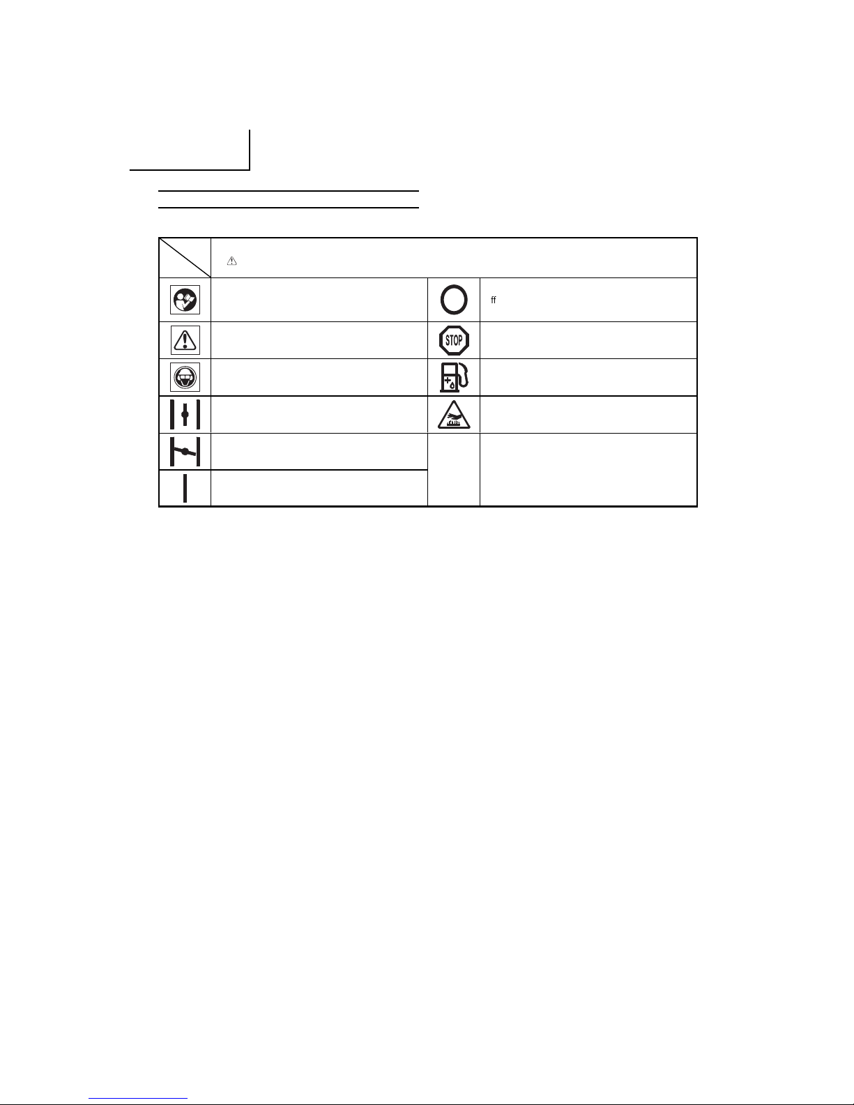
MEANINGS OF SYMBOLS
NOTE: Some units do not carry them.
Symb ols
WARNIN G
The foll owing show symbols used for the machin e. Be sure that you understa nd their meaning before us e.
It is important that you read, fully understand and
obser ve the followi ng safety precautions and
warnings. Careless or improper use of the unit may
cause serious or fatal injury.
O /Stop
Read, understand and follow all warnings and
instructions in this manual and on the unit.
Emergency stop
Always wear eye, hea d and e ar protectors when using
this uni t.
Fuel and o il mixture
Choke - Run position (Open) Hot sur face
Choke - Choked position (Closed)
Befo re using your ma chine
• Read the manual carefully.
• Check that the cut ting equipme nt is correctly
assembled and adjusted.
• Star t the unit and check the carburetor adjustment.
See “MA INTENANCE”.
On/St art
Conten ts
WHAT IS WHAT? ..............................................................................5
WARNINGS AND SAFETY INSTRUCTIONS ..................................6
SPECIFICATIONS ............................................................................ 7
OPERATING PROCEDURES ........................................................... 7
MAINTENANCE ................................................................................8
TROUBLESHOOTING ...................................................................... 9
Page 5
5
English
5
8
12
9
1
2
15
4
6
3
11
16
14
10
7
13
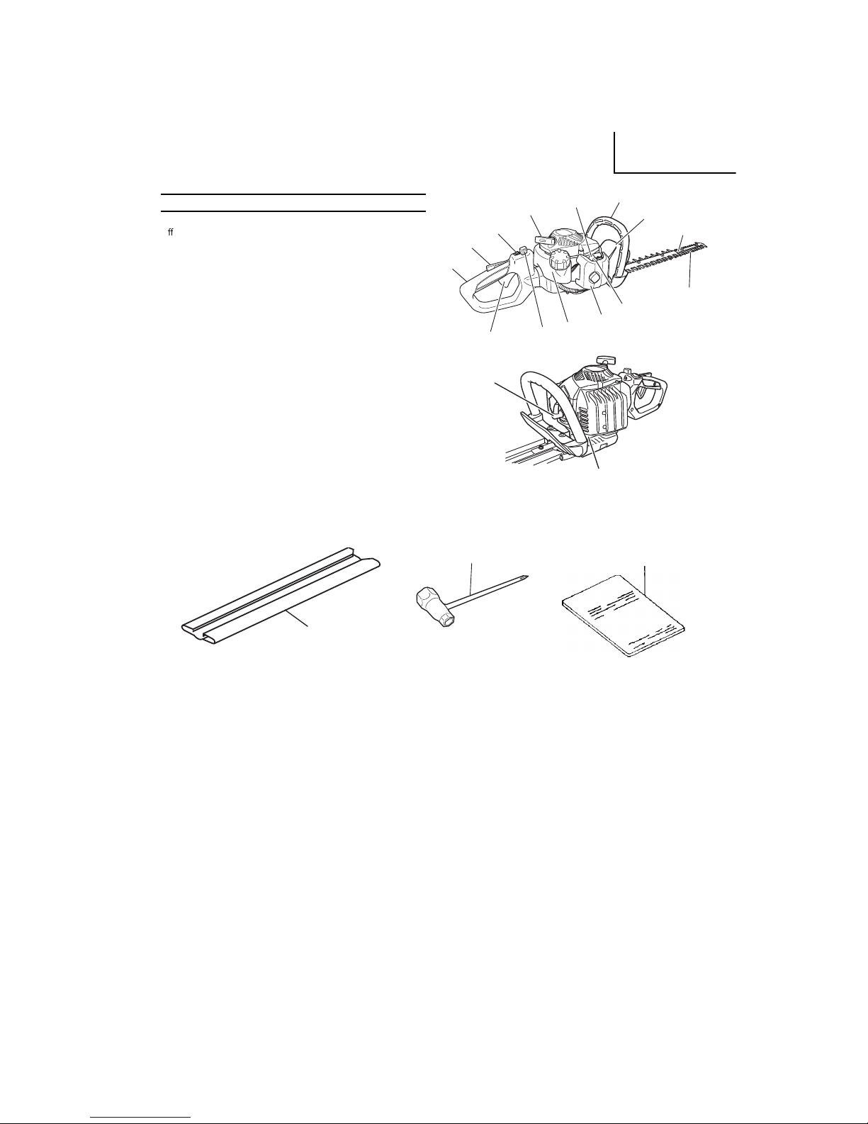
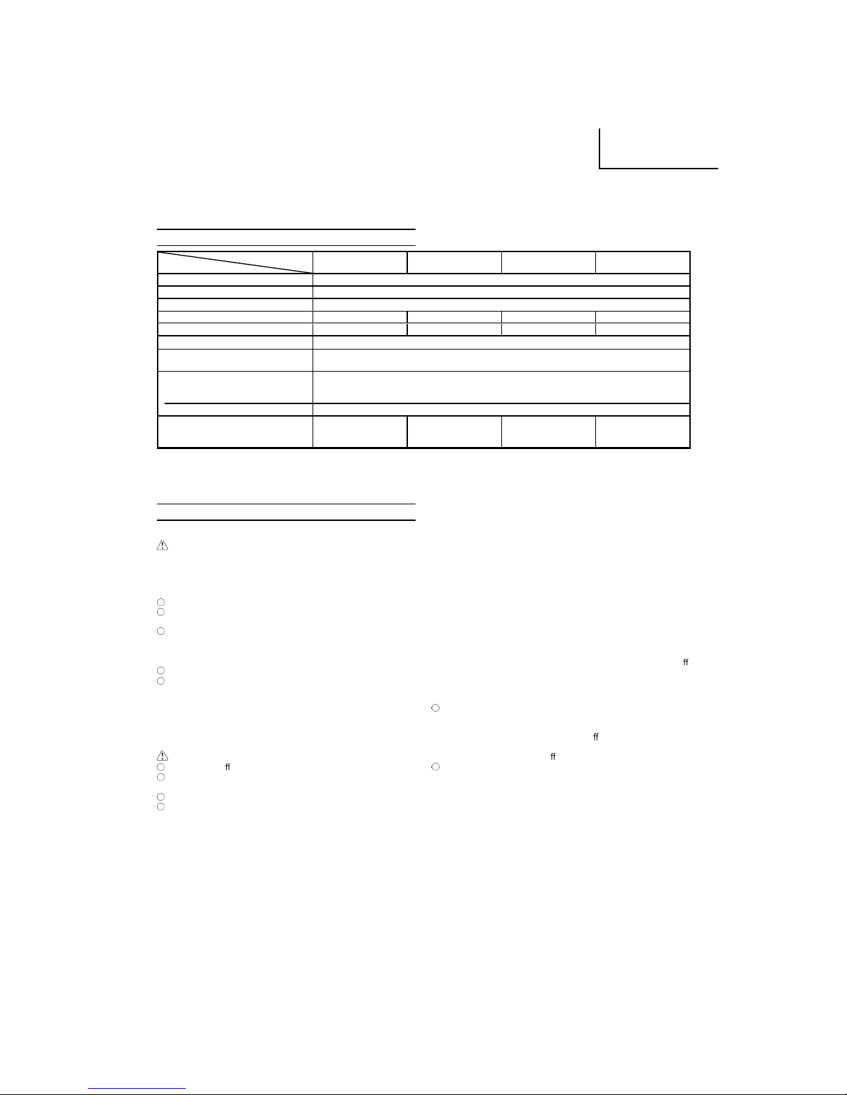
WHAT IS WHAT?
Since thi s manual covers several m odels, there may be some
di eren ce between these illustrations and your unit. Use the
instructions that apply to your unit.
1. Re coil starter
2. Fuel tank
3. Th rottle lever lockout
4. Th rottle lever
5. Front handle
6. Rea r handle
7. Spark plug
8. Hand guard
9. Cu tting blade
10. Air cleaner
11. Stop switch
12. Blade guide
13. Gear case
14. Choke lever
15. Lock lever
16. Primi ng pump
17. Blade case
18. Combi box spanner
19. Handling instr uctions
17
18
19
CH 22EAP2 (50ST), CH 22EA2 (50ST )
CH 22EBP2 (62ST), CH 22EB2 (62ST)
CH 22ECP2 (62ST), CH 22EC2 (6 2ST)
CH 22ECP2 (78ST), CH 22EC2 (78ST)
Page 6

6
English
WARNINGS AND SAFETY INSTRUCTIONS
Keep fo r future refe rence.
THIS HEDGE TRIMMER CAN CAUSE SERIOUS INJURIES. Rea d
the instructions carefully for the correct ha ndling, preparation,
maintenance, starting and stopping of the hedge tr immer. Become
familiar with all controls and the proper use of the hedge tri mmer.
Oper ator safe ty
Always wear a safety face shield or goggles.
Always wea r heavy, long pants, boots and gloves. Do not wear
loose clothi ng, jewelry, short pants, sanda ls or go barefo ot.
Secure hair so it is above shoul der length.
Do not operate this tool when you are tired, ill or under the
infl uence of alcohol, dru gs or medicati on.
Never let a child or inexperienced person operate the machine.
Beware of overh ead power lines.
Wea r hearing protection.
Never start or run the en gine inside a closed room or building.
Breath ing exhaust fumes can kill.
Keep handles free of oil and fuel.
Keep hands away from cutting equipment.
Do not grab or hold the unit by the cutting equipment.
When the unit is turned o , make sure the cutting attachment
has stopped befor e the unit is set down.
When operation is prolon ged, take a break from time to time
so that yo u may avoid possible Hand-Arm Vibration Syndrome
(HAVS) which is caused by vibration.
If the cutting mechanis m strikes any foreign object or the
hedge trimmer starts making any unusual noise or vibration,
shut o the power source and allow the hedg e trimmer to stop.
Disconnect th e spark pl ug wire from the spark plu g and take the
followi ng steps:
Inspect for damage;
Check for, and tighten, any loose parts;
Have any damaged parts replaced or repaired with parts
having equivalen t specifi cations.
WARNING
Antivibration systems do not guar antee that you will not sustain
Hand-Arm Vibration S yndrome or c arpal tunnel syndr ome.
Therefore, continual and regular users should monitor closely
the condition of their hands and fi nger s. If any sy mptoms of th e
above appear, seek medical advice immediately.
If you are using any medica l electri c/electroni c devices such
as a pacemaker, consult your physician as well a s the device
manufacturer pr ior to operating any power equipment.
When a fore ign obje ct is caught in the bla de, turn o the
engine, and remove the foreign obje ct carefully using a plier
etc., af ter the hedge trimmer has been cooled down. Be careful
when removin g the foreign object, since the blade may move
because of the back lash.
Unit /machine safety
Inspect the entire un it/machine before e ach u se. Re place
damaged parts. Check for fuel le aks and make sure all
fasten ers are in place and securely tightened.
Rep lace parts that are cracked, chippe d or damaged in any way
before using the uni t/machine .
Keep others away when making carburetor adjustments.
Use only accessorie s as rec ommended for this unit /machine by
the manu facturer.
WARNING
Never modify the unit /machine in an y way. Do not u se your unit/
machine for any job except that for which it is intended.
Fuel sa fety
Mix and pour fuel outdoors and where there are no sparks or
fl ames.
Use a contain er approved for fuel.
Never remove the fuel cap or add fuel with the power source
runni ng. Allow engine and exhaust compone nts to cool down
before refuellin g.
Do not smoke or allow smokin g near fuel or the unit/m achine or
while using the unit/mach ine.
Never refuel in doors.
Wipe up all fuel spills before starting engine.
Move at least 3 m away from fueling site befo re starting engine.
Stop engine before removing fuel cap.
Empty the fuel tank before storing the unit/machi ne. It i s
recommended that the fuel be emptied af ter each use. If fuel is
left in the tank, store so fuel will not leak.
Store unit/mach ine and f uel in ar ea where fuel vapors cannot
reach sparks or open fl ames from water heaters, electric motors
or switches, furnaces, etc.
WARNING
Fuel is easy to ignite or get explosion or inhale fumes, so tha t
pay special atten tion when handling or fi lling fuel.
Cutti ng safet y
Do not cut any material other than plant hedge.
Inspect the area to be cut before each use. Remove objects
which can be thrown or become entangled.
For respiratory protec tion, wear an aerosol protection mask
when cutting the grass after insecticide is scattered.
Keep others including ch ildren, ani mals, bystanders and
helper s o utside the 15 m hazard zone. Stop t he engine
immedi ately if you are approached.
Hold the unit /machine fi rmly with both hands.
Keep fi rm footing and balance. Do not over-reach.
Keep all parts of your body away from the mu er and cutting
attachment when the engin e is running.
Keep cuttin g tool below shoulder level. NEVER operate uni t
from a ladder, while in a tree or from an y unstab le support.
When relocating to a new work area, be sure to shut o the
machine and ensure that all cutting attachme nts are stopped.
Never place the machine on the groun d when ru nning.
Always carry a fi rst-aid kit when operating any power
equipment.
Never st art or run the engine inside a closed room or buil ding
and/or near the infl ammable liquid. Breathi ng exhaust fumes
can kill.
Mainte nance sa fety
Maintain the unit/mach ine accordi ng to r ecommended
procedures.
Di sconnect t he spa rk plu g before performing mainten ance
except for carburetor adjustments.
Keep others away when making carburetor adjustments.
Use only genuine Hitachi replacement pa rts as reco mmended
by the man ufacturer.
When the h edge trimmer is stopped for servicing, inspection or
storage, shut o the power source, disconn ect the spark pl ug
wire from t he spark plug and make sure all moving parts have
come to a stop.
Allow the hedge trimmer to cool before maki ng any inspecti on,
adjustments, etc .
Transpor t and stora ge
Car ry the unit/mac hine by ha nd wi th th e eng ine stopped and
the mu er away from your body.
Allow the engine to c ool, empty the fuel tank, and secure the
unit /machin e before storin g or transporti ng in a vehicle.
Empty the fuel tank before storing the unit/machi ne. It i s
recommended that the fuel be emptied af ter each use. If fuel is
left in the tank, store so fuel will not leak.
Store unit /machin e out of the reach of children.
Cl ean and maintenance the unit carefully an d store it in a dry
place.
Make sure engine switch is o when transporting or storing.
When trans porting in a vehic le or storage, co ver blade with
blade cover.
If situations occur which are not covered in this manual, take care
and use common sense. Contact your Hitachi deale r if you need
assistance. Pay special attention to stateme nts preceded by the
followi ng words:
WARNING
Indicates a strong possibilit y of severe personal injur y or loss of
life, if in structions are not followed.
CAUTIO N
Indicates a possibility of per sonal inju ry or equ ipment damage,
if instruction s are not followed.
Page 7
7
English
NOTE
Helpful information for correct function and use.
SPECIFICATIONS
MODEL
CH22EAP2 (50ST)
CH22EA2 (50ST)
CH22EBP2 (62ST)
CH22EB2 (62ST)
CH22ECP2 (62ST)
CH22EC2 (62ST)
CH22ECP2 (78ST)
CH22EC2 (78ST)
Engine Size (ml) 21.1
Spark Pl ug NGK BMR 7A (Europ e and Australia) or Champion CJ 6 (other regions)
Fuel Tank Capac ity (l) 0.30
Dry Weight (kg) 4.3 4.7 5.0 5.2
Overall blade length (mm) 500 620 620 780
Blade t ype
Double-sided
Sound pressure level
LpA (dB(A)) (ISO 10517) 97
Sound power level
Lw measured (dB (A))
(2000/14/EC, ISO 10517)
102
LwA (dB (A)) 104
Vibration level (m/s2) (ISO 10517)
Front handle
Rear han dle
7.0
7.5
9.1
9.1
2.8
3.4
2.8
2.8
NOTE
Equi valent noise level/vibration level are calculated as the time-we ighted energy total for noi se/vibration levels under var ious working
condit ions with the fo llowing time distribution : ISO 10517.....1/5 idle, 4/5 rac ing. 2000/14/EC.....only racing .
* All data subjec t to change with out notice.
OPERATING PROCEDURES
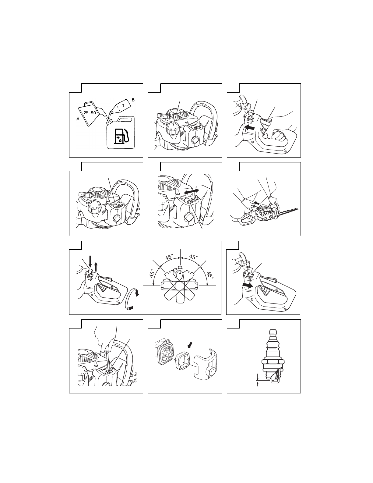
Fuel (Fig . 1)
WARNIN G
The hedge tri mmer is equipped wi th a two- stroke engine.
Always run the engin e on fuel, mixed with oil.
Provide good ventilation, when fueling or handling fuel.
Fuel
Always use branded 89 octane unleaded gasoline.
Use genuine two-cycle oil or use a mix be tween 25:1 to 50:1,
please consult the oil bot tle for the ratio or Hitachi dealer.
If genuine oil is not available, use an anti -oxidant added qua lity
oil expressly labeled for air-cooled 2-cycle engine use (JASO
FC GR ADE OIL or ISO EGC GRADE ). Do not use BIA or TCW
(2-stroke water-cooling type) mixed oil.
Never use mult i-grade oil (10W/30) or waste oil.
Always mix fuel and oil in a se parate cl ean containe r.
Always start by fi lling half the amount of fuel, which is to be used.
Then add the whole amount of oil. Mix (shake) the fuel mixture. Add
the rema ining amount of fuel.
Mix (shake) the fuel-mix thoroughly before fi l ling the fuel ta nk.
Fueling
WARNIN G (Fig. 2)
Always shut o the engine before refue ling.
Slowly open the fuel ta nk (1), wh en fi lling up with fuel, so that
possi ble over-pressure disappears.
Ti ghten the fuel ca p carefully, after fueling .
Always move the unit at lea st 3 m from the fueling area before
starting.
Before fu eling, clean t he tank cap area ca refully, to ensur e that
no dirt falls into the tank. Make sure th at the fuel is wel l mixed by
shaking the cont ainer, before fueling.
Star ting
CAUTIO N
Before starting, make sure the cutting attachment does not
touch anything.
1. Set stop sw itch (2) to ON position (A). (Fig. 3)
* Push priming pump (4) severa l times so that fuel fl ows through
the pump or return pipe. (Fig. 4)
CAUTIO N
Do not dis assemble the recoil starter. you may get a possibili ty
of personal injury with recoil spring.
2. Set choke l ever (5) to CLOSED position (B). (Fig. 5)
3. Pull recoil s tarter briskly, taking ca re to keep the handle in your
grasp and not allowing it to snap back. (Fig. 6)
4. When you hear the e ngine attempts to start, ret urn choke lever
to RUN position (open) (C). Then pull re coil starter briskly
again.
NOTE
If engine does not start, repeat pro cedures from 2 to 4.
5. After st arting engine, allow the engine about 2-3 minute s to
warm up before subjecting it to any load.
Cutti ng
When cutting, operate engine at full throttle as this maintains proper
blade speed. When trimming top of hedge, hold trimmer so blades
are between 15 an d 30 degrees fr om a horizont al position and
swing t rimmer in an arc toward edge of hedge to sweep cut tings o .
When trimming sides of hedge, hold blade vertically and swing unit
in an arc.
NOTE
Multi-position twist handle (Fig. 7)
The rear control handle turns 90 degre es to provide
comfortable use while accommodating a variety of cutting
angles. The handle allows for fi ve di er ent locking positions.
Before attempti ng to adjust rear handle, make sure the machine
is at idle or engine is shut o .
Th e throttle lever cannot be engaged i f t he handle i s n ot
secured (the lock lever is pressed).
To rotate the handle; push the lock lever (6) allowing the handl e
to turn. Rotate the handle to the desired 0°, 4 5° or 90° locking
posit ion and release the lock lever (6) to lock the handle in
place.
D: LOCK
E: UNLOCK
Stopp ing (Fig. 8)
Decrea se engine speed, and push stop switch to stop position (F).
NOTE
If the engi ne does not stop, it can be forced to stop by r otating
the choke lever to the choked position.
Before restar ting the engine, ask Hitachi Au thorized Service
Centers for repairs.
Page 8

8
English
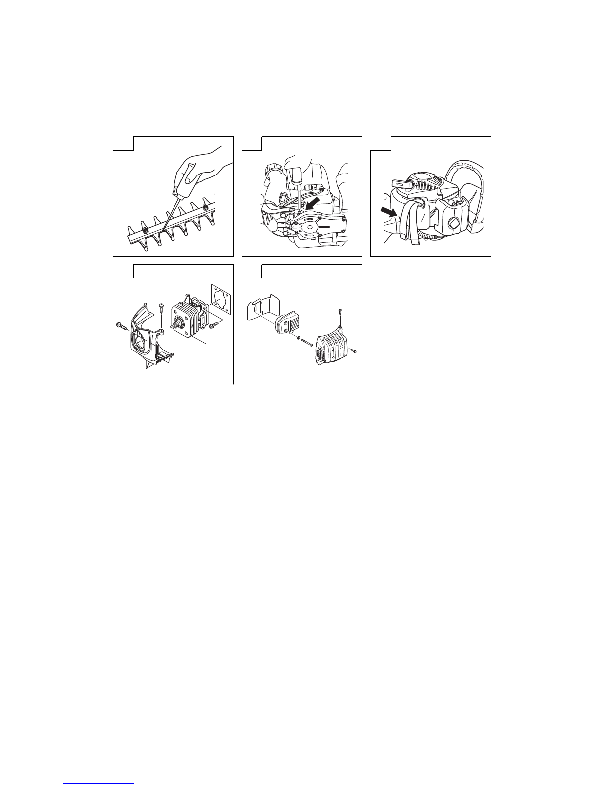
Lubri cating th e blade (Fig.12)
During trimming, sap adhering to the blade edge will increase load.
Use machine o il (or bicycl e oil or the like) to lubricate the blade and
wipe the blade with a cloth. To prevent the blade from rusting, be
sure to lubricate the blade after use and when it will not be used for
an exten ded period of time before placing it in the blade case.
Gear c ase (Fig. 13)
Apply a good quality lithium base d greas e throu gh the grease fi t ting
until a small amount co mes out between the cutting blades and the
gear case. Lubricate the grease from th e grease nipple (indicated
by an arrow) next to the gear case using a commercia lly available
cartridge grease gun.
NOTE
Lubricatio n should be applied 3g at 20 hour interval s and more
freque ntly with heav y use.
Fuel fi lter (Fig. 14)
Remove the fuel fi lter from the fu el tank and thoroughly wash it i n
solvent. After that, push the fi l ter into th e tank co mpletely.
NOTE
If the fi lter is hard due to dust and dirt, repl ace it.
Clea ning the cyli nder fi n s (Fig. 15)
When leaves get ca ught bet ween cylinder fi ns (7), the engine may
overhea t, resulting in lower output. To avoid th is, always keep
cylinder fi ns and cylinder cover clean.
Every 100 operating hours, or once a year (more often if conditions
require), clean fi ns an d external surfaces of eng ine of dust, dirt and
oil depo sits which ca n contribute to improper cooling.
Clea ning the mu er (Fig. 16)
Remove the mu er and spark arrestor (if so equipped), and clean
out any excess ca rbon from the exhaust port or mu er inlet every
100 hours of operati on.
For lon g-term s torage
Drain all fuel from the fuel tank . Start and let engine run until it stops.
Repair any damage which has resulted from use. Clean the unit with
a clea n rag, or high pressure air hose. Put a few drops of two-cycle
engine oil into the cylinder through the spark plug h ole, and spin t he
engine over several times to distribute oil. Cover the unit and store
it in a dry area.
Mainte nance sch edule
Below you will fi nd some general maintenance instructions. For
further inform ation please contact yo ur Hitachi dealer.
Daily maintenanc e
Cl ean the exterior of the hedge trimmer.
Ch eck the blade guide for damage or cr acks. Change the guard
in case of impacts or cracks.
Ch eck that the blade is sharp, and without cracks.
Ch eck that the blade nut is su ciently tightened.
Make sure that the blade blu nt guard is undamaged and that it
can be securely fi tted.
Ch eck that nuts and screws are su ciently tightened.
Weekl y maintena nce
Ch eck the starter, especia lly cord and retu rn spring.
Cl ean the exterior of the spar k plug.
Rem ove it and check the electrode gap. Adjust it to 0.6 mm, or
change the spark plug.
Cl ean t he cooling fi ns on the cylinder and check that the air
intake at the starter is not clo gged.
Ch eck gear case is fi lled with gre ase.
Cl ean the air fi lter.
Mont hly mainte nance
Rinse the fuel tank with gasoline.
Cl ean the exterior of the car buretor and the space around it.
Cl ean the fan and the space arou nd it.
MAINTENANCE
MAINTENANCE, REPLACEMENT OR REPAIR OF THE EMISSION
CONTROL DEV ICES AND SYSTEM MAY BE PERFORMED
BY ANY NONROAD ENGINE REPAIR ESTABLISHMENT OR
INDIVIDUAL.
Carbu retor adjus tment (Fig . 9)
WARNING
Th e cutting attachment may be spinning during car buretor
adjustments.
Never start the eng ine without the complete cleaner cover.
Other wise t he clutch can come loose and cause personal
injuries.
In the carburetor, fu el is mixed with air. When the engine is tes t run
at the factory, th e carburetor is adjusted. A further adjustment may
be required, according to climate and altitude. The ca rburetor has
one adjustment possibility:
T = Idle s peed adjus tment scr ew.
Idle s peed adjus tment (T)
Check that the air fi lter is clean. Wh en the idle speed is corr ect, the
cutting attachment will not r otate. If adjustment is required, close
(clock wise) the T-screw, with the engine running, until the cutting
attachment starts to rotate. Open (cou nter-clock wise) the screw
until th e cutting attachment stops. You have reached the co rrect idle
speed when the engine run s smoothly in all positions well below the
rpm when the cutting attachment starts to rotate.
If the cutting attachment still rotates after idle speed adjustme nt,
contac t Hitachi dealer.
Air fi lter (Fig . 10)
The air fi lter must be cleaned from dust and dir t in order to avoid:
Car buretor malfunction s.
Starting problems.
En gine power reduction.
Unn ecessary wear on the engine par ts.
Abnormal fuel consu mption.
Clean the air fi lter daily or more often if working in exceptionally
dusty areas.
Clea ning the air fi lt er
Remove th e cleaner cover and the fi lter. Rinse it in warm soa p suds.
Check that the fi lter is dry before reassembly. An air fi lter that has
been used for some time cannot be cleaned completely. Therefore,
it must regularly be rep laced by a new one. A damaged fi lter must
always be replaced.
NOTE
Saturate the ele ment in 2-cycle oil or the e quivalent. Squeeze
the element to distribute the oil completely and to remove any
excess oil.
Spar k plug (Fig. 11)
The spark plug con dition is infl uenced by:
An incorrec t carburetor s etting.
Wrong fuel mix ture (too much oil in the gasoline).
A dirty air fi lter.
Ha rd running conditions (such as cold weather).
These factors cause deposits on the spark plug electrodes, which
may result in mal function and star ting di culties. If t he engine
is low on power, di cult to start or runs poorly at idling speed,
always check the spark plug fi r st. If the spark pl ug is dirty, clean it
and check the electrode gap. Readju st i f nece ssary. The correct
gap is 0.6 mm. Th e spark plug should be replaced after about 100
operation hours or earlie r i f the electrodes are badly erode d.
NOTE
In some areas, local law requires using a resistor spark plug
to suppress ignition sign als. If this machine was originally
equipped with resistor spark plug, use the same type of spar k
plug for replacem ent.
Page 9

9
English
TROUBLESHOOTING
Use the inspe ctions in the table below if the tool does not operate n ormally. If this does not remedy the problem, c onsult your dealer or th e
Hitachi Authorized Service Center.
Symptom Possible cause Remedy
Tool Does not operate. Foreign matter is lodged in th e blade. When there is foreign matter in the blade, use a
pair of tongs or similar tool to remove it.
Take great care since the tool may start
operating when the foreign matter has been
removed.
Sap or rust may also prevent the blade from
operating. Use a wi re brus h or similar tool to
remove sap or rust.
The tool does not tri m well. The blade stopped because it was used to cut
a branch whose width exceede d the blade’s
cutting capaci ty.
NOTE
Work that will repeatedly cause the bla de to
stop wil l e ve ntually damag e the tool.
Some garden trees have wood tha t is very
hard and may be beyond the capaci ty of the
tool even if it is of a width that is within normal
capacity. Use a pair of pruning shear to remo ve
thick branches before starting work.
An oblique cut may also exceed the capacit y of
the tool since the le ngth of the cut increases.
Be sure to trim thick branche s at right angles.
Page 10

CH22EA2 (50ST)
74
Page 11

CH22EA2 (50ST)
Item
No.
Part Name Q’TY
1 COVER FIXING BOLT COMP. 1
2 CLEANER C OVER 1
3 CLEANER SPONGE 1
4 CHOKE VALVE 1
5
MACHINE SCREW
(W/WASHERS) M5×60
2
6 CLEANER BO DY 1
7 CHOKE HANDL E 1
8
TAPPING SCREW (W/FL ANGE)
D4×12
1
9
THROTTLE ADJUST SCREW
(TAS)
1
10 SE T SCREW (B) 3
11 SE T SCREW (D) 4
12 SYR INGE 1
13 PRI MER BASE 1
14 PUMP G ASKET 1
15 PUMP DIAPHRAGM 1
16 ST RAINER 1
17 GUI DE PIN ROLLER 1
18 SYR INGE RETAINER 1
19 SE T SCREW (E) 1
20 BALL PLUG RETAINER 1
21
ADJUSTING SC REW
(MAIN MIXTUR E)
1
22 METERING L EVER SPRING 1
23 PIN 1
24 METERING DIAPHRAGM 1
25 METERING COVER 1
26 SET SCREW (C) 3
27 POST 1
28 ROTOR COVER 1
29
RETAINING RING (E-TYPE) FOR
D2.5 SHAFT
1
30 O-RING 1
31 INLET NEEDLE VALVE 1
32 SET SCREW (A) 1
33 METERING L EVER 1
34 METERING GA SKET 1
35
CARBURETOR ASS 'Y
(INCLUD.9-3 4)
1
36 LOCK NUT M6 1
37 CARBURETOR INSU LATOR 1
38 INTAKE PACKING 1
39 GLASS WASHER 4
40 CARBURETOR PACKING 1
41
SEAL LOCK HEX . SOCKET
BOLT (W/WASHERS)M5×25
2
42
HEX. SOCKET HD. BOLT
(W/WASHERS) M4×18
2
43 CORD 1
44
SEAL LOCK HEX . SOCKET HD.
BOLT M4×12
1
45 CYLINDER COVER 1
46 METAL OF PLUG CAP (60) (B) 1
47 PLUG CAP 1
48 CORD INSUL ATION TUBE 1
49 IGNITION COIL 1
50 SPARK PLUG 1
51 CYLI NDER 1
52 COVER PACKING 2
53 INTAKE COVER (A) 1
54 SEAL LOCK SCRE W M 4×10 4
55 HEAT PROTECTION PANEL 1
56 MUFFLER 1
57 BOLT WASHER M6 2
58 HEX. SOCKET HD. BOLT M6×55 2
Item
No.
Part Name Q’TY
59 INTAKE COVER (B) 1
60 PISTON PIN 1
61 PISTON 1
62
HEX. SOCKET HD. BOLT
(W/SP.WAS HER) M5×18
8
63 CYLINDER PACKING 1
64 PISTON RING 1
65 CIR CLIP 2
66 FLYWHEEL NUT M7 1
67 BOLT WASHER D7 1
68 STARTER PAWL 2
69 STARTER PAWL SPRING 2
70 MAGNETO ROTOR 1
71 RETAINING RING D4 2
72
CRANK CASE (B) ASS'Y
(INCLUD.73,74)
1
73 OIL SEAL TB 12227 2
74 BALL BE ARING 6001C3 2
75 SHIM T0.2 1
76 SHIM T0.3 1
77 CRANK SHAF T 1
78
CRANK CASE (A) ASS'Y
(INCLUD.73,74,80)
1
79 CRANK CASE PACKING 1
80 KNOCK PIN 4×12 2
81 CLUTCH ASS'Y (B) 1
82 CLUTCH DRUM 1
83 BALL BEARIN G 6002ZC3 2
84
RETAINING RING FOR D15
SHAFT
1
85 GREASE NIPPLE COMP. 1
86
TAPPING SCREW (W/FL ANGE)
D5X20
1
87 MUFFLER PROTECTOR 1
88
MACHINE SCREW
(W/SP.WAS HERS) M5×16
1
89 HEX. HOLE B OLT 6×18/S 4
90
HEX. SOCKET HD. BOLT
(W/BUTTON) M5×20
2
91 FIXATION PLATE (A) 1
92 FIXATION PLATE (B) 1
93 TAIL PIPE (A) 1
94 EXHAUST COVER 1
95 HITACHI LABEL 1
96 TAPPING SCREW D4.5×16 1
97 PLATE 1
98 STARTER KNOB 1
99 STARTER ROPE 1
100
HEX. SOCKET HD. BOLT
(W/BUTTON) M5×20
3
101 RECOIL SPRING 1
102 STARTER ROPE REEL 1
103 DAMPER SPRING 1
104 CAM PLATE 1
105 SET SCREW 1
106
RECOIL STARTER ASS'Y
(INCLUD.97-99,101-10 5)
1
107 AIR DEFLECTOR 1
108
FUEL TANK CAP ASS'Y
(INCLUD.109)
1
109 TANK CAP CHAIN 1
110 F UEL GROMMET 1
111 FUEL PIPE 1
112 F UEL PIPE (PINK) 1
113 R ETURN GROMMET 1
114 C LIP 1
115 P UMP FILTER 1
Item
No.
Part Name Q’TY
116 C USHION RUBBER 4
117 TANK 1
141 NAME PLATE 1
142 HANDLE 1
143
SEAL LOCK HEX . SOCKET HD.
BOLT M5×40
2
144 SPRING WASHER M5 2
145 BRAKE AXI S WASH ER 2
146 HANDLE A 1
147 CAUTION LABEL 1
148 SPRING (A) 1
149 LOCK LEVER 1
150 THROTTLE LEV ER 1
151 TRIGGER LOCKOUT 1
152 THROTTLE LEV ER SPRING 1
153 STOP SWITCH 1
154 HANDLE B 1
155
TAPPING SCREW (W/FL ANGE)
D4×16
4
156 THROTTLE WIRE 1
157 PROTECTION TUBE 1
158 STOP SWITCH CORD 1
159 STOP SWITCH CORD (B) 1
160 FIXATION PLATE (B) 1
161 NYLON NUT M5 2
162 SMALL WASHER 5 2
163 SPACER 1
164
HEX. SOCKET HD. BOLT
(W/BUTTON) M5×25
2
165 U-NUT M5 5
166 WASHER (B) 5
167 WASHER M7 5
168
SHOULDER BUTTON BOLT
M5×25
5
169 BLADE ASS'Y (INCLUD.164-16 8) 1
170 BLADE CASE (A) 1
171 HANDLE BRACKET 1
172 CLIP 1
173 BOLT WASHER D5 3
174
SEAL LOCK HEX . SOCKET
BOLT (W/WASHERS) M5×16
3
175
GEAR CASE (A) ASS'Y
(INCLUD.176)
1
176 GUIDE PLATE (C) 1
177 GEAR 2 1
178 GUIDE PLATE (A) 1
179 FELT PA CKING (A) 1
180 GEAR CASE PACKING 1
181 GEAR CASE COVER 1
182
HEX. SOCKET HD. BOLT
(W/SP.WAS HER) M5×12
6
501 BOX WRENCH 10/19MM 1
75
Page 12

CH22EBP2 (62ST)
76
Page 13

Item
No.
Part Name Q’TY
1 COVER FIXING BOLT COMP. 1
2 CLEANER C OVER 1
3 CLEANER SPONGE 1
4 CHOKE VALVE 1
5
MACHINE SCREW
(W/WASHERS) M5×60
2
6 CLEANER BO DY 1
7 CHOKE HANDL E 1
8
TAPPING SCREW (W/FL ANGE)
D4×12
1
9
THROTTLE ADJUST SCREW
(TAS)
1
10 SE T SCREW (B) 3
11 SE T SCREW (D) 4
12 SYR INGE 1
13 PRI MER BASE 1
14 PUMP G ASKET 1
15 PUMP DIAPHRAGM 1
16 ST RAINER 1
17 GUI DE PIN ROLLER 1
18 SYR INGE RETAINER 1
19 SE T SCREW (E) 1
20 BALL PLUG RETAINER 1
21
ADJUSTING SC REW
(MAIN MIXTUR E)
1
22 METERING L EVER SPRING 1
23 PIN 1
24 METERING DIAPHRAGM 1
25 METERING COVER 1
26 SET SCREW (C) 3
27 POST 1
28 ROTOR COVER 1
29
RETAINING RING (E-TYPE) FOR
D2.5 SHAFT
1
30 O-RING 1
31 INLET NEEDLE VALVE 1
32 SET SCREW (A) 1
33 METERING L EVER 1
34 METERING GA SKET 1
35
CARBURETOR ASS 'Y
(INCLUD.9-3 4)
1
36 LOCK NUT M6 1
37 CARBURETOR INSU LATOR 1
38 INTAKE PACKING 1
39 GLASS WASHER 4
40 CARBURETOR PACKING 1
41
SEAL LOCK HEX . SOCKET
BOLT (W/WASHERS)M5×25
2
42
HEX. SOCKET HD. BOLT
(W/WASHERS) M4×18
2
43 CORD 1
44
SEAL LOCK HEX . SOCKET HD.
BOLT M4×12
1
45 CYLINDER COVER 1
46 METAL OF PLUG CAP (60) (B) 1
47 PLUG CAP 1
48 CORD INSUL ATION TUBE 1
49 IGNITION COIL 1
50 SPARK PLUG 1
51 CYLI NDER 1
52 COVER PACKING 2
53 INTAKE COVER (A) 1
54 SEAL LOCK SCRE W M 4×10 4
55 HEAT PROTECTION PANEL 1
56 MUFFLER 1
57 BOLT WASHER M6 2
58 HEX. SOCKET HD. BOLT M6×55 2
59 INTAKE COVER (B) 1
Item
No.
Part Name Q’TY
60 PISTON PIN 1
61 PISTON 1
62
HEX. SOCKET HD. BOLT
(W/SP.WAS HER) M5×18
8
63 CYLINDER PACKING 1
64 PISTON RING 1
65 CIR CLIP 2
66 FLYWHEEL NUT M7 1
67 BOLT WASHER D7 1
68 STARTER PAWL 2
69 STARTER PAWL SPRING 2
70 MAGNETO ROTOR 1
71 RETAINING RING D4 2
72
CRANK CASE (B) ASS'Y
(INCLUD.73,74)
1
73 OIL SEAL TB 12227 2
74 BALL BE ARING 6001C3 2
75 SHIM T0.2 1
76 SHIM T0.3 1
77 CRANK SHAF T 1
78
CRANK CASE (A) ASS'Y
(INCLUD.73,74,80)
1
79 CRANK CASE PACKING 1
80 KNOCK PIN 4×12 2
81 CLUTCH ASS'Y (B) 1
82 CLUTCH DRUM 1
83 BALL BEARIN G 6002ZC3 2
84
RETAINING RING FOR D15
SHAFT
1
85 GREASE NIPPLE COMP. 1
86
TAPPING SCREW (W/FL ANGE)
D5×20
1
87 MUFFLER PROTECTOR 1
88
MACHINE SCREW
(W/SP.WAS HERS) M5×16
1
89 HEX. HOLE B OLT 6×18/S 4
90
HEX. SOCKET HD. BOLT
(W/BUTTON) M5×20
2
91 FIXATION PLATE (A) 1
92 FIXATION PLATE (B) 1
93 TAIL PIPE (A) 1
94 EXHAUST COVER 1
95 HITACHI LABEL 1
96 TAPPING SCREW D4.5×16 1
97 PLATE 1
98 STARTER KNOB 1
99 STARTER ROPE 1
100
HEX. SOCKET HD. BOLT
(W/BUTTON) M5×20
3
101 RECOIL SPRING 1
102 STARTER ROPE REEL 1
103 DAMPER SPRING 1
104 CAM PLATE 1
105 SET SCREW 1
106
RECOIL STARTER ASS'Y
(INCLUD.97-99,101-10 5)
1
107 AIR DEFLECTOR 1
108
FUEL TANK CAP ASS'Y
(INCLUD.109)
1
109 TANK CAP CHAIN 1
110 F UEL GROMMET 1
111 FUEL PIPE 1
112 F UEL PIPE (PINK) 1
113 R ETURN GROMMET 1
114 C LIP 1
115 P UMP FILTER 1
116 C USHION RUBBER 4
117 TANK 1
Item
No.
Part Name Q’TY
118 CAUTION LABEL 1
141 NAME PLATE 1
142 HANDLE 1
143
SEAL LOCK HEX . SOCKET HD.
BOLT M5×40
2
144 SPRING WASHER M5 2
145 BRAKE AXI S WASH ER 2
146 HANDLE A 1
147 CAUTION LABEL 1
148 SPRING (A) 1
149 LOCK LEVER 1
150 THROTTLE LEV ER 1
151 TRIGGER LOCKOUT 1
152 THROTTLE LEV ER SPRING 1
153 STOP SWITCH 1
154 HANDLE B 1
155
TAPPING SCREW (W/FL ANGE)
D4×16
4
156 THROTTLE WIRE 1
157 PROTECTION TUBE 1
158 STOP SWITCH CORD 1
159 STOP SWITCH CORD (B) 1
160 FIXATION PLATE (B) 1
161 NYLON NUT M6 2
162 BOLT WASHER 6 2
163 U-NUT M5 5
164 WASHER (A) 2
165 RUBBER WASHER 2
166 COLLER 1
167 SUPPORT PLATE 1
168 BOLT WASHER D6 2
169
BLADE ASS' Y
(INCLUD.163,172-173)
1
170
HEX. SOCKET HD. BOLT
(W/FLANGE) M5×8
1
171 GUARD PLATE 1
172
HEX. SOCKET HD. BOLT
(W/BUTTON) M6×25
1
173 WASHER (A) 5
174 WASH ER M7 5
175
SHOULDER BUTTON BOLT
M5×25
4
176
SHOULDER BUTTON BOLT
M5×31
1
177 BLADE CASE 1
178 HANDLE BRACKE T 1
179 CLIP 1
180 BOLT WASHER D5 3
181
SEAL LOCK HEX . SOCKET
BOLT (W/WASHERS) M5×16
3
182
GEAR CASE (A) ASS'Y
(INCLUD.183)
1
183 BALL BEARING 608ZZC3 2
184
HEX. SOCKET HD. BOLT
(W/BUTTON) M6×25
1
185 GUIDE PLATE (B) 2
186 CAM ROD 2
187 GEAR 2 1
188 FELT PACKING (B) 2
189 FELT PACKING (C) 1
190 GEAR CASE PACKING 1
191
GEAR CASE (B) ASS'Y
(INCLUD.183)
1
192
HEX. SOCKET HD. BOLT
(W/SP.WAS HER) M5×14
6
501 BOX WRENCH 10/19MM 1
CH22EBP2 (62ST)
77
Page 14

CH22EB2 (62ST)
78
Page 15

CH22EB2 (62ST)
Item
No.
Part Name Q’TY
1 COVER FIXING BOLT COMP. 1
2 CLEANER C OVER 1
3 CLEANER SPONGE 1
4 CHOKE VALVE 1
5
MACHINE SCREW
(W/WASHERS) M5×60
2
6 CLEANER BO DY 1
7 CHOKE HANDL E 1
8
TAPPING SCREW (W/FL ANGE)
D4×12
1
9
THROTTLE ADJUST SCREW
(TAS)
1
10 SE T SCREW (B) 3
11 SE T SCREW (D) 4
12 SYR INGE 1
13 PRI MER BASE 1
14 PUMP G ASKET 1
15 PUMP DIAPHRAGM 1
16 ST RAINER 1
17 GUI DE PIN ROLLER 1
18 SYR INGE RETAINER 1
19 SE T SCREW (E) 1
20 BALL PLUG RETAINER 1
21
ADJUSTING SC REW
(MAIN MIXTUR E)
1
22 METERING L EVER SPRING 1
23 PIN 1
24 METERING DIAPHRAGM 1
25 METERING COVER 1
26 SET SCREW (C) 3
27 POST 1
28 ROTOR COVER 1
29
RETAINING RING (E-TYPE) FOR
D2.5 SHAFT
1
30 O-RING 1
31 INLET NEEDLE VALVE 1
32 SET SCREW (A) 1
33 METERING L EVER 1
34 METERING GA SKET 1
35
CARBURETOR ASS 'Y
(INCLUD.9-3 4)
1
36 LOCK NUT M6 1
37 CARBURETOR INSU LATOR 1
38 INTAKE PACKING 1
39 GLASS WASHER 4
40 CARBURETOR PACKING 1
41
SEAL LOCK HEX . SOCKET
BOLT (W/WASHERS)M5×25
2
42
HEX. SOCKET HD. BOLT
(W/WASHERS) M4×18
2
43 CORD 1
44
SEAL LOCK HEX . SOCKET HD.
BOLT M4×12
1
45 CYLINDER COVER 1
46 METAL OF PLUG CAP (60) (B) 1
47 PLUG CAP 1
48 CORD INSUL ATION TUBE 1
49 IGNITION COIL 1
50 SPARK PLUG 1
51 CYLI NDER 1
52 COVER PACKING 2
53 INTAKE COVER (A) 1
54 SEAL LOCK SCRE W M 4×10 4
55 HEAT PROTECTION PANEL 1
56 MUFFLER 1
57 BOLT WASHER M6 2
58 HEX. SOCKET HD. BOLT M6×55 2
59 INTAKE COVER (B) 1
Item
No.
Part Name Q’TY
60 PISTON PIN 1
61 PISTON 1
62
HEX. SOCKET HD. BOLT
(W/SP.WAS HER) M5×18
8
63 CYLINDER PACKING 1
64 PISTON RING 1
65 CIR CLIP 2
66 FLYWHEEL NUT M7 1
67 BOLT WASHER D7 1
68 STARTER PAWL 2
69 STARTER PAWL SPRING 2
70 MAGNETO ROTOR 1
71 RETAINING RING D4 2
72
CRANK CASE (B) ASS'Y
(INCLUD.73,74)
1
73 OIL SEAL TB 12227 2
74 BALL BE ARING 6001C3 2
75 SHIM T0.2 1
76 SHIM T0.3 1
77 CRANK SHAF T 1
78
CRANK CASE (A) ASS'Y
(INCLUD.73,74,80)
1
79 CRANK CASE PACKING 1
80 KNOCK PIN 4×12 2
81 CLUTCH ASS'Y (B) 1
82 CLUTCH DRUM 1
83 BALL BEARIN G 6002ZC3 2
84
RETAINING RING FOR D15
SHAFT
1
85 GREASE NIPPLE COMP. 1
86
TAPPING SCREW (W/FL ANGE)
D5×20
1
87 MUFFLER PROTECTOR 1
88
MACHINE SCREW
(W/SP.WAS HERS) M5×16
1
89 HEX. HOLE B OLT 6×18/S 4
90
HEX. SOCKET HD. BOLT
(W/BUTTON) M5×20
2
91 FIXATION PLATE (A) 1
92 FIXATION PLATE (B) 1
93 TAIL PIPE (A) 1
94 EXHAUST COVER 1
95 HITACHI LABEL 1
96 TAPPING SCREW D4.5×16 1
97 PLATE 1
98 STARTER KNOB 1
99 STARTER ROPE 1
100
HEX. SOCKET HD. BOLT (W/
BUTTON) M5×20
3
101 RECOIL SPRING 1
102 STARTER ROPE REEL 1
103 DAMPER SPRING 1
104 CAM PLATE 1
105 SET SCREW 1
106
RECOIL STARTER ASS'Y
(INCLUD.97-99,101-10 5)
1
107 AIR DEFLECTOR 1
108
FUEL TANK CAP ASS'Y
(INCLUD.109)
1
109 TANK CAP CHAIN 1
110 F UEL GROMMET 1
111 FUEL PIPE 1
112 F UEL PIPE (PINK) 1
113 R ETURN GROMMET 1
114 C LIP 1
115 P UMP FILTER 1
116 C USHION RUBBER 4
117 TANK 1
Item
No.
Part Name Q’TY
141 NAME PLATE 1
142 HANDLE 1
143
SEAL LOCK HEX . SOCKET HD.
BOLT M5×40
2
144 SPRING WASHER M5 2
145 BRAKE AXI S WASH ER 2
146 HANDLE A 1
147 CAUTION LABEL 1
148 SPRING (A) 1
149 LOCK LEVER 1
150 THROTTLE LEV ER 1
151 TRIGGER LOCKOUT 1
152 THROTTLE LEV ER SPRING 1
153 STOP SWITCH 1
154 HANDLE B 1
155
TAPPING SCREW (W/FL ANGE)
D4×16
4
156 THROTTLE WIRE 1
157 PROTECTION TUBE 1
158 STOP SWITCH CORD 1
159 STOP SWITCH CORD (B) 1
160 FIXATION PLATE (B) 1
161 NYLON NUT M6 2
162 BOLT WASHER 6 2
163 U-NUT M5 5
164 WASHER (A) 2
165 RUBBER WASHER 2
166 COLLER 1
167 SUPPORT PLATE 1
168 BOLT WASHER D6 2
169
BLADE ASS' Y
(INCLUD.163,172-173)
1
170
HEX. SOCKET HD. BOLT
(W/FLANGE) M5×8
1
171 GUARD PLATE 1
172
HEX. SOCKET HD. BOLT
(W/BUTTON) M6×25
1
173 WASHER (A) 5
174 WASH ER M7 5
175
SHOULDER BUTTON BOLT
M5×25
4
176
SHOULDER BUTTON BOLT
M5×31
1
177 BLADE CASE 1
178 HANDLE BRACKE T 1
179 CLIP 1
180 BOLT WASHER D5 3
181
SEAL LOCK HEX . SOCKET
BOLT (W/WASHERS) M5×16
3
182
GEAR CASE (A) ASS'Y
(INCLUD.183)
1
183 BALL BEARING 608ZZC3 2
184
HEX. SOCKET HD. BOLT
(W/BUTTON) M6×25
1
185 GUIDE PLATE (B) 2
186 CAM ROD 2
187 GEAR 2 1
188 FELT PACKING (B) 2
189 FELT PACKING (C) 1
190 GEAR CASE PACKING 1
191
GEAR CASE (B) ASS'Y
(INCLUD.183)
1
192
HEX. SOCKET HD. BOLT
(W/SP.WAS HER) M5×14
6
501 BOX WRENCH 10/19MM 1
79
Page 16

CH22ECP2 (62ST) / CH22ECP2 (78ST)
80
Page 17

CH22ECP2 (62ST) / CH22ECP2 (78ST)
Item
No.
Part Name Q’TY
1 COVER FIXING BOLT COMP. 1
2 CLEANER C OVER 1
3 CLEANER SPONGE 1
4 CHOKE VALVE 1
5
MACHINE SCREW
(W/WASHERS) M5×60
2
6 CLEANER BO DY 1
7 CHOKE HANDL E 1
8
TAPPING SCREW (W/FL ANGE)
D4×12
1
9
THROTTLE ADJUST SCREW
(TAS)
1
10 SE T SCREW (B) 3
11 SE T SCREW (D) 4
12 SYR INGE 1
13 PRI MER BASE 1
14 PUMP G ASKET 1
15 PUMP DIAPHRAGM 1
16 ST RAINER 1
17 GUI DE PIN ROLLER 1
18 SYR INGE RETAINER 1
19 SE T SCREW (E) 1
20 BALL PLUG RETAINER 1
21
ADJUSTING SC REW
(MAIN MIXTUR E)
1
22 METERING L EVER SPRING 1
23 PIN 1
24 METERING DIAPHRAGM 1
25 METERING COVER 1
26 SET SCREW (C) 3
27 POST 1
28 ROTOR COVER 1
29
RETAINING RING (E-TYPE)
FOR D2.5 SHAF T
1
30 O-RING 1
31 INLET NEEDLE VALVE 1
32 SET SCREW (A) 1
33 METERING L EVER 1
34 METERING GA SKET 1
35
CARBURETOR ASS 'Y
(INCLUD.9-3 4)
1
36 LOCK NUT M6 1
37 CARBURETOR INSU LATOR 1
38 INTAKE PACKING 1
39 GLASS WASHER 4
40 CARBURETOR PACKING 1
41
SEAL LOCK HEX . SOCKET
BOLT (W/WASHERS)M5×25
2
42
HEX. SOCKET HD. BOLT
(W/WASHERS) M4×18
2
43 CORD 1
44
SEAL LOCK HEX . SOCKET HD.
BOLT M4×12
1
45 CYLINDER COVER 1
46 METAL OF PLUG CAP (60) (B) 1
47 PLUG CAP 1
48 CORD INSUL ATION TUBE 1
49 IGNITION COIL 1
50 SPARK PLUG 1
51 CYLI NDER 1
52 COVER PACKING 2
53 INTAKE COVER (A) 1
54 SEAL LOCK SCRE W M 4×10 4
55 HEAT PROTECTION PANEL 1
56 MUFFLER 1
57 BOLT WASHER M6 2
58
HEX. SOCKET HD. BOLT
M6×55
2
Item
No.
Part Name Q’TY
59 INTAKE COVER (B) 1
60 PISTON PIN 1
61 PISTON 1
62
HEX. SOCKET HD. BOLT
(W/SP.WAS HER) M5×18
8
63 CYLINDER PACKING 1
64 PISTON RING 1
65 CIR CLIP 2
66 FLYWHEEL NUT M7 1
67 BOLT WASHER D7 1
68 STARTER PAWL 2
69 STARTER PAWL SPRING 2
70 MAGNETO ROTOR 1
71 RETAINING RING D4 2
72
CRANK CASE (B) ASS'Y
(INCLUD.73,74)
1
73 OIL SEAL TB 12227 2
74 BALL BE ARING 6001C3 2
75 SHIM T0.2 1
76 SHIM T0.3 1
77 CRANK SHAF T 1
78
CRANK CASE (A) ASS'Y
(INCLUD.73,74,80)
1
79 CRANK CASE PACKING 1
80 KNOCK PIN 4X12 2
81 CLUTCH ASS'Y (B) 1
82 CLUTCH DRUM 1
83 BALL BEARIN G 6002ZC3 2
84
RETAINING RING FOR D15
SHAFT
1
85 GREASE NIPPLE COMP. 1
86
TAPPING SCREW (W/FL ANGE)
D5×20
1
87 MUFFLER PROTECTOR 1
88
MACHINE SCREW
(W/SP.WAS HERS) M5×16
1
89 TAIL PIPE 1
90 FIXATION PLATE (A) 1
91
MACHINE SCREW
(W/WASHERS) M4×10
1
92 FIXATION PLATE (B) 1
93 HEX. HOLE BOLT 6×18/S 4
94 HITACHI LABEL 1
95 TAPPING SCREW D4.5×16 1
96 PLATE 1
97 STARTER KNOB 1
98 STARTER ROPE 1
99
HEX. SOCKET HD. BOLT
(W/BUTTON) M5×20
3
100 RECOIL SPRING 1
101 STARTER ROPE REEL 1
102 DAMPER SPRING 1
103 CAM PLATE 1
104 SET SCREW 1
105
RECOIL STARTER ASS'Y
(INCLUD.97-99,101-10 5)
1
106 AIR DEFLECTOR 1
107
FUEL TANK CAP ASS'Y
(INCLUD.109)
1
108 TANK CAP CHAIN 1
109 FUEL GROMMET 1
110 F UEL PIPE 1
111 FUEL PIPE (PINK) 1
112 R ETURN GROMMET 1
113 C LIP 1
114 P UMP FILTER 1
115 C USHION RUBBER 4
116 TANK 1
Item
No.
Part Name Q’TY
117 CAUTION LABEL 1
141
HEX. SOCKET HD. BOLT
(W/FLANGE) M6×32
4
142 FRONT HANDLE 1
143 CAUTION LABEL 1
144 FRAME 1
145 NAME PLATE 1
146 DAMPER 1
147 HANDLE A 1
148 FLEXIBLE GRO MMET 1
149 SPRING (A) 1
150 LOCK LEVER 1
151 THROTTLE LEVE R 1
152 TRIGGER LOCKOUT 1
153 THROTTLE LEV ER SPRING 1
154 STOP SWITCH 1
155 HANDLE B 1
156
TAPPING SCREW (W/FL ANGE)
D4×16 (BLACK)
4
157 THROTTLE WIRE 1
158 PROTECTION TUBE 1
159 STOP SWITCH CORD 1
160 STOP SWITCH CORD (B) 1
161
HEX. SOCKET HD. BOLT
(W/FLANGE) M6×22
4
162 CLIP 1
163 NYLON NUT M6 2
164 BOLT WASHER 6 2
165 U-NUT M5 5
166 WASHER (A) (FOR 620MM) 2
167
RUBBER WASHER
(FOR 620MM)
2
168 COLLAR (FOR 620 MM) 1
169 SUPPORT PLATE 1
171 SPRING HOLDER 4
172
HEX. SOCKET HD. BOLT
(W/FLANGE) M5×10
4
173 ANTIVIBR ATION SPR ING 4
174
BLADE ASS' Y
(INCLUD.165,177-181)
1
175
HEX. SOCKET HD. BOLT
(W/FLANGE) M5×8
1
176 GUARD PLATE 1
177
HEX. SOCKET HD. BOLT
(W/BUTTON) M6×25
1
178 WASHER (A) 5
179 WASHER M7 5
180
SHOULDER BUTTON BOLT
M5×25
4
181
SHOULDER BUTTON BOLT
M5×31
1
182 BLADE CASE 1
183
GEAR CASE (A) ASS'Y
(INCLUD.184)
1
184 BALL BEARIN G 608ZZC3 2
185
HEX. SOCKET HD. BOLT
(W/BUTTON) M6×25
1
186 GUIDE PLATE (B) 2
187 CAM ROD 2
188 GEAR 2 1
189 FELT PACKING (B) 2
190 FELT PACKING (C) 1
191 GEAR CASE PACKING 1
192
GEAR CASE (B) ASS'Y
(INCLUD.184)
1
193
HEX. SOCKET HD. BOLT
(W/SP.WAS HER) M5×14
6
501 BOX WRENCH 10/19MM 1
81
Page 18

CH22EC2 (62ST) / CH22EC2 (78ST)
82
Page 19

CH22EC2 (62ST) / CH22EC2 (78ST)
Item
No.
Part Name Q’TY
1 COVER FIXING BOLT COMP. 1
2 CLEANER C OVER 1
3 CLEANER SPONGE 1
4 CHOKE VALVE 1
5
MACHINE SCREW
(W/WASHERS) M5×60
2
6 CLEANER BO DY 1
7 CHOKE HANDL E 1
8
TAPPING SCREW (W/FL ANGE)
D4X12
1
9
THROTTLE ADJUST SCREW
(TAS)
1
10 SE T SCREW (B) 3
11 SE T SCREW (D) 4
12 SYR INGE 1
13 PRI MER BASE 1
14 PUMP G ASKET 1
15 PUMP DIAPHRAGM 1
16 ST RAINER 1
17 GUI DE PIN ROLLER 1
18 SYR INGE RETAINER 1
19 SE T SCREW (E) 1
20 BALL PLUG RETAINER 1
21
ADJUSTING SC REW
(MAIN MIXTUR E)
1
22 METERING L EVER SPRING 1
23 PIN 1
24 METERING DIAPHRAGM 1
25 METERING COVER 1
26 SET SCREW (C) 3
27 POST 1
28 ROTOR COVER 1
29
RETAINING RING (E-TYPE) FOR
D2.5 SHAFT
1
30 O-RING 1
31 INLET NEEDLE VALVE 1
32 SET SCREW (A) 1
33 METERING L EVER 1
34 METERING GA SKET 1
35
CARBURETOR ASS 'Y
(INCLUD.9-3 4)
1
36 LOCK NUT M6 1
37 CARBURETOR INSU LATOR 1
38 INTAKE PACKING 1
39 GLASS WASHER 4
40 CARBURETOR PACKING 1
41
SEAL LOCK HEX . SOCKET
BOLT (W/WASHERS)M5×25
2
42
HEX. SOCKET HD. BOLT
(W/WASHERS) M4×18
2
43 CORD 1
44
SEAL LOCK HEX . SOCKET HD.
BOLT M4×12
1
45 CYLINDER COVER 1
46 METAL OF PLUG CAP (60) (B) 1
47 PLUG CAP 1
48 CORD INSUL ATION TUBE 1
49 IGNITION COIL 1
50 SPARK PLUG 1
51 CYLI NDER 1
52 COVER PACKING 2
53 INTAKE COVER (A) 1
54 SEAL LOCK SCRE W M 4×10 4
55 HEAT PROTECTION PANEL 1
56 MUFFLER 1
57 BOLT WASHER M6 2
58 HEX. SOCKET HD. BOLT M6×55 2
59 INTAKE COVER (B) 1
Item
No.
Part Name Q’TY
60 PISTON PIN 1
61 PISTON 1
62
HEX. SOCKET HD. BOLT
(W/SP.WAS HER) M5×18
8
63 CYLINDER PACKING 1
64 PISTON RING 1
65 CIR CLIP 2
66 FLYWHEEL NUT M7 1
67 BOLT WASHER D7 1
68 STARTER PAWL 2
69 STARTER PAWL SPRING 2
70 MAGNETO ROTOR 1
71 RETAINING RING D4 2
72
CRANK CASE (B) ASS'Y
(INCLUD.73,74)
1
73 OIL SEAL TB 12227 2
74 BALL BE ARING 6001C3 2
75 SHIM T0.2 1
76 SHIM T0.3 1
77 CRANK SHAF T 1
78
CRANK CASE (A) ASS'Y
(INCLUD.73,74,80)
1
79 CRANK CASE PACKING 1
80 KNOCK PIN 4×12 2
81 CLUTCH ASS'Y (B) 1
82 CLUTCH DRUM 1
83 BALL BEARIN G 6002ZC3 2
84
RETAINING RING FOR D15
SHAFT
1
85 GREASE NIPPLE COMP. 1
86
TAPPING SCREW (W/FL ANGE)
D5X20
1
87 MUFFLER PROTECTOR 1
88
MACHINE SCREW
(W/SP.WAS HERS) M5×16
1
89 TAIL PIPE 1
90 FIXATION PLATE (A) 1
91
MACHINE SCREW
(W/WASHERS) M4×10
1
92 FIXATION PLATE (B) 2
93 HEX. HOLE BOLT 6×18/S 4
94 HITACHI LABEL 1
95 TAPPING SCREW D4.5×16 1
96 PLATE 1
97 STARTER KNOB 1
98 STARTER ROPE 1
99
HEX. SOCKET HD. BOLT
(W/BUTTON) M5×20
3
100 RECOIL SPRING 1
101 STARTER ROPE REEL 1
102 DAMPER SPRING 1
103 CAM PLATE 1
104 SET SCREW 1
105
RECOIL STARTER ASS'Y
(INCLUD.97-99,101-10 5)
1
106 AIR DEFLECTOR 1
107
FUEL TANK CAP ASS'Y
(INCLUD.109)
1
108 TANK CAP CHAIN 1
109 FUEL GROMMET 1
110 F UEL PIPE 1
111 FUEL PIPE (PINK) 1
112 R ETURN GROMMET 1
113 C LIP 1
114 P UMP FILTER 1
115 C USHION RUBBER 4
116 TANK 1
Item
No.
Part Name Q’TY
141
HEX. SOCKET HD. BOLT
(W/FLANGE) M6×32
4
142 FRONT HANDLE 1
143 CAUTION LABEL 1
144 FRAME 1
145 NAME PLATE 1
146 DAMPER 1
147 HANDLE A 1
148 FLEXIBLE GRO MMET 1
149 SPRING (A) 1
150 LOCK LEVER 1
151 THROTTLE LEVE R 1
152 TRIGGER LOCKOUT 1
153 THROTTLE LEV ER SPRING 1
154 STOP SWITCH 1
155 HANDLE B 1
156
TAPPING SCREW (W/FL ANGE)
D4×16 (BLACK)
4
157 THROTTLE WIRE 1
158 PROTECTION TUBE 1
159 STOP SWITCH CORD 1
160 STOP SWITCH CORD (B) 1
161
HEX. SOCKET HD. BOLT
(W/FLANGE) M6×22
4
162 CLIP 1
163 NYLON NUT M6 2
164 BOLT WASHER 6 2
165 U-NUT M5 5
166 WASHER (A) (FOR 620MM) 2
167
RUBBER WASHER
(FOR 620MM)
2
168 COLLAR (FOR 620 MM) 1
169 SUPPORT PLATE 1
171 SPRING HOLDER 4
172
HEX. SOCKET HD. BOLT
(W/FLANGE) M5×10
4
173 ANTIVIBR ATION SPR ING 4
174
BLADE ASS' Y
(INCLUD.165,177-181)
1
175
HEX. SOCKET HD. BOLT
(W/FLANGE) M5×8
1
176 GUARD PLATE 1
177
HEX. SOCKET HD. BOLT
(W/BUTTON) M6×25
1
178 WASHER (A) 5
179 WASHER M7 5
180
SHOULDER BUTTON BOLT
M5×25
4
181
SHOULDER BUTTON BOLT
M5×31
1
182 BLADE CASE 1
183
GEAR CASE (A) ASS'Y
(INCLUD.184)
1
184 BALL BEARIN G 608ZZC3 2
185
HEX. SOCKET HD. BOLT
(W/BUTTON) M6×25
1
186 GUIDE PLATE (B) 2
187 CAM ROD 2
188 GEAR 2 1
189 FELT PACKING (B) 2
190 FELT PACKING (C) 1
191 GEAR CASE PACKING 1
192
GEAR CASE (B) ASS'Y
(INCLUD.184)
1
193
HEX. SOCKET HD. BOLT
(W/SP.WAS HER) M5×14
6
501 BOX WRENCH 10/19MM 1A
83
Page 20

84
Page 21

85
Page 22

86
Page 23

Englis h Nederlands
Object of declaration: Hitachi Hedge Trimmer CH22EAP2, CH22EBP2, CH22ECP2
EC DECLARATION OF CONFORMITY
(Applies to Europe only)
We declare under our sole responsibility that this product is in conformity with Directive
2006/42 /EC, 2004/108/EC and 2000/14/EC. The following standards have been taken
into consideration.
ISO 10517, EN55012
Annex V (2000/14/EC):
Measured sound power level: 102 dB
Guaranteed sound power level: 104 dB
The European Standards Manager at Hitachi Koki Europe Ltd. i s authorized to compil e
the technical fi le.
This declaration is applicable to the product a xed CE marking.
Onderwerp van verklaring: Hitachi Motor heggenschaar CH22EAP2, CH22EBP2, C H22ECP2
EC VERKLARING VAN CONFORMITEIT
(Geldt alleen voor Euro pa)
Wij verklaren onder ei gen verantwoordelijkheid dat dit product voldoet aan de richtlijn
2006/42 /EC, 2004/108/EC en 2000/14/EC. De volgende standaards zijn toegepast .
ISO 10517, EN55012
Aanvulling V (2000/14/EC):
Gemeten geluidsdruk: 102 dB
Gegarandeerde geluidsdruk: 104 dB
De manager voor Europese normen van Hitachi Koki Europe Ltd. heeft de bevoegdheid
tot het samenstellen van het technische bestand.
Deze verklaring is van toepassing op produkten voorzien van de CE-markeringen.
Deuts ch Españo l
Gegenstand der Erklärung: Hitachi Heckenschere CH22EAP2, CH22EBP2, CH22ECP2
EG-KONFORMITÄTSERKLÄRUNG
(Gilt nur für Europa)
Wir erklären eigenverantwortlich, dass dieses Produkt den Bestimmungen der Ri chtlinien
2006/42 /EG, 2004/108/EG und 2000/14/EG des Europäischen Rates entspricht. Die
nachfol genden Standards wurden in Betracht gezogen.
ISO 10517, EN55012
Anhang V (2000/14/EG):
Gemessener Schallleistungspegel: 102 dB
Garantierter Schallleistungspegel: 104 dB
Der Manager für europäische Standard s be i der Hitachi Koki Europe Ltd. ist zum Verfassen
der technischen Datei befugt.
Diese Erklärung gilt für Produkte, die die CE-Markierung tragen.
Objeto de declaración: Hitachi Cortasetos CH22EAP2, CH22EBP2, CH22ECP2
DECLARACIÓN DE CONFORMIDAD DE LA CE
(De aplicación sólo en Eu ropa)
Declaramos bajo nuestra exclusiva responsabilidad que este producto es conforme con
las Direct ivas 2006/42/CE, 2004/108/CE y 2000/14/CE. Se han teni do en consideración
las siguientes normas.
ISO 10517, EN55012
Anexo V (2000/14/CE):
Nivel de potencia acústica medida: 102 dB
Nivel de potencia acústica garantizada: 104 dB
El Jefe de Normas Europeas de Hitachi Koki Europe Ltd. está autorizado para recopilar
archivos técnicos.
Esta declaración se aplica a los productos con marcas de la CE.
França is
Português
Objet de la déclaration: Hitachi Taille-Haies CH22EAP2, CH22EBP2, CH22ECP2
DECLARATION DE CONFORMITE CE
(Concerne l’Euro pe uniquement)
Nous déclarons sur la foi de notre seule responsabilité que ce produit est conforme aux
dispositions des Directives du Conseil de l'Union européenne 2006/42/EC, 2004/108/EC
et 2000/14/EC. Les nonnes suivantes ont été prises en considération.
ISO 10517, EN55012
Annexe V (2000/14/EC):
Niveau de puissance sonore mesuré: 102 dB
Niveau de puissance sonore garanti: 104 dB
Le responsable des normes européennes d’Hitac hi Koki Europe Ltd. est au torisé à compi ler
les données techniques.
Cette déclaration s’applique aux produits désignés CE.
Objeto de declaração: Hi tachi Corta-sebes CH22EAP2, CH22EBP2, CH22ECP2
DECLARAÇÃO DE CONFORMIDADE CE
(Aplica-se apena s à Europa)
Declaramos para os devidos efeitos que este produto cumpre os requisitos das directivas
comunitárias 2006/42/CE, 2004/108/CE e 2000/14/CE. As seguintes normas harmonizadas
foram aplicadas.
ISO 10517, EN55012
Anexo V (2000/14/CE):
Nível medido de potência de som: 102 dB
Nível garantido de potência de som: 104 dB
O Gestor de Normas Europeias da Hitachi Koki Europe Ltd. está autorizado a compilar
o fi cheiro técnico.
Esta declaração se aplica aos produtos designados CE.
Italia no
Oggetto della dichiarazione: Hitachi Tosasiepi CH22EAP2, CH22EBP2, CH22ECP2
DICHIARAZIONE DI CONFORMITÀ CE
(Si applica solo all ’Europa)
Dichiariamo sotto la nostra esclusiva responsabilit à che questo prodotto è conforme
alle Direttive del Consiglio 2006/42 /CE, 2004/108/CE e 2000/14/CE. Sono stati presi in
considerazione i seguenti standard.
ISO 10517, EN55012
Allegato V (2000/14/CE):
Livello di potenza sonora misurato: 102 dB
Livello di potenza sonora garantito: 104 dB
Il Responsabil e dell e Norme Europee di Hitachi Koki Ltd. è autorizzato a compilare la
scheda tecnica.
Questa dichiarazione è applicabile ai prodotti cui sono applicati i marchi CE.
Hitachi Koki Europe Ltd.
Clonshaugh Business & Technology Park, Dublin 17, lreland
Representative o ce in Europe
Hitachi Power Tools Europe GmbH
Siemensring 34, 47877 Willich 1, F. R. Germany
Head o ce in Japan
Hitachi Koki Co., Ltd.
Shinagawa Intercity Tower A, 15-1, Konan 2-chome,
Minato-ku, Tokyo, Japan
28. 4. 2013
Mr. John de Loughry
European Standards and
Compliance Manager
28. 4. 2013
F. Tashimo
Vice-President & Director
Page 24

304
Code No. E99252872 NA
Printed in China
Svenska Norsk
Objekt för deklaration: Hitachi Häcksax CH22EAP2, CH22EBP2, CH22ECP2
EF-DEKLARATION BETRÄFFANDE LIKFORMIGHET
(Gäller endast Europa)
Vi int ygar under ensamt ansvar, att denna produkt motsvarar bestämmelserna i direktiven
2006/42 /EF, 2004/108/EF och 2000/14/EF.
Vi har tagit hänsyn till följande standards.
ISO 10517, EN55012
Bilaga V (2000/14/EF):
Uppmätt ljudstyrkenivå: 102 dB
Garanterad ljudstyrkenivå: 104 dB
Den europeiska standardan svarige på Hi tachi Koki Europe Ltd. är a uktoriserad att utarbeta
den tekniska fi len.
Denna deklaration gäller för CE-märkningen pà produkten.
Erklæringens objekt: Hitachi Hekksaks CH22EAP2, CH22EBP2, CH22ECP2
EF’S ERKLÆRING OM OVERENSSTEMMELSE
(Gjelder bare for Europa)
Vi erklærer med vårt eneansvar at dette produktet er i overensstemmelse med EU direktiv
2006/42 /EF, 2004/108/EF og 2000/14/EF.
Det er tatt hensyn ti l følgende standarder.
ISO 10517, EN55012
Anneks V (2000/14/EF):
Målt lyde ektnivå: 102 dB
Garantert lyde ektnivå: 104 dB
Lederen for europeiske standarder ved Hitachi Koki Europe Ltd. har fullmakt til å utarbeide
det tekniske dokumentet.
Denne erklæringen gjelder produktets påklistrede CE-merking.
Dansk Suomi
Genstand for erklæring: Hitachi Hækkeklipper CH22EAP2, CH22EBP2, CH22ECP2
EF-OVERENSS TEMMELSESERKLÆRING
(Gælder kun for Europa)
Vi erklærer som eneansvarlige, at dette produkt er i overensstemmelse med Rådsdirektiv
2006/42 /EF, 2004/108/EF og 2000/14/EF.
De følgende standarder har været iagttaget.
ISO 10517, EN55012
Appendiks V (2000/14/EF):
Målt lydstyrkeniveau: 102 dB
Garanteret lydstyrkeniveau: 104 dB
Chefen for e uropæiske sta ndarder hos Hitachi Koki Europe Ltd. er autoriseret til at kompilere
den tekniske fi l.
Denne erklæring qælder produkter, der er mærket med CE.
Ilmoituksen kohde: Hitachi Pensasl eikkuri CH22EAP2, CH22EBP2, CH22ECP2
EY-ILMOITUS YHDENMUKAISUUDESTA
(Koskee vain Eurooppaa)
Ilmoitamme yksinomaisella vastuullamme, että tämä tuote on direktiivien 2006/42/EY,
2004/108/EY ja 2000/14/EY vaatimusten mukainen.
Seuraavat standardit on huomioitu.
ISO 10517, EN55012
Liite V (2000/14/EY):
Mitattu äänenpainetaso: 102 dB
Taat tu äämempanetaso: 104 dB
Hitachi Koki Europe Ltd.:n eurooppalaisten standardien johtaja on valtuutettu laatimaan
tekniset asiakirjat.
Tämä ilmoitus sovelletaan tuotekohtaiseen CE-merkintään.
Hitachi Koki Europe Ltd.
Clonshaugh Business & Technology Park, Dublin 17, lreland
Representative o ce in Europe
Hitachi Power Tools Europe GmbH
Siemensring 34, 47877 Willich 1, F. R. Germany
Head o ce in Japan
Hitachi Koki Co., Ltd.
Shinagawa Intercity Tower A, 15-1, Konan 2-chome,
Minato-ku, Tokyo, Japan
28. 4. 2013
Mr. John de Loughry
European Standards and
Compliance Manager
28. 4. 2013
F. Tashimo
Vice-President & Director
 Loading...