

Page 1
Backpack Brush Cutter
Desbrozadora de mochila
Roçadora dorsal
CG 40EBF (L)
Read the manual carefully before operating this machine.
Antes de utilizar esta máquina, lea cuidadosamente el manual.
Leia o manual atentamente antes de operar esta máquina.
Handling instructions
Instrucciones de manejo
Instruções de uso
Page 2
123
10
8
1
5
2
6
7
3
4
5
2
9
10
456
16
11
12
14
13
15
78
2
Page 3
910
11 12 13
A
B
17
14 15 16
B
C
A
17 18 19
19
T
A
B
20
18
3
Page 4
20 21 22
23
4
Page 5
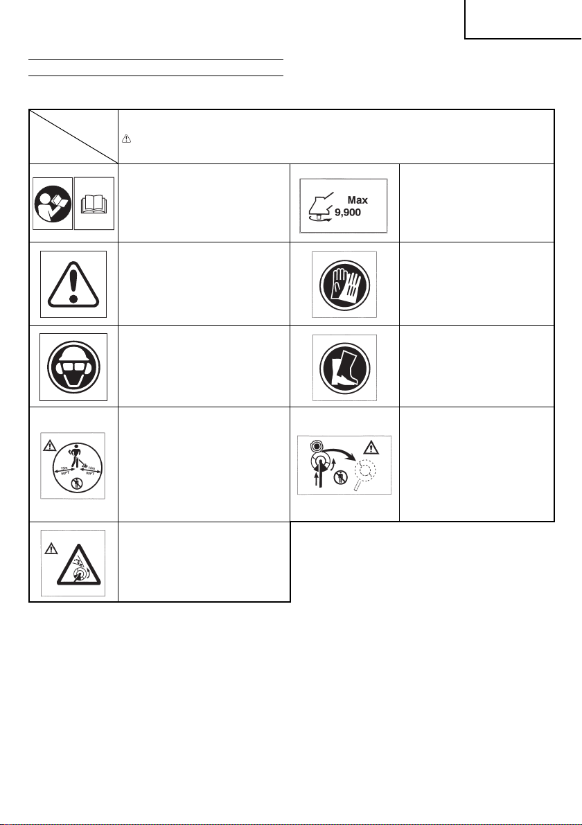
MEANINGS OF SYMBOLS
NOTE: Some units do not c arry them.
Symbols
WARNING
The foll owing show symbols used for the machine. B e sure that you understand their meaning before use.
It is important that you read, fully
understand and observe the following
safety precautions and warnings.
Carele ss or improper use of the unit may
cause serious or fatal injur y.
min
Shows ma ximum shaft s peed. Do not
use the cutting attachment whose max
-1
speed is below th e shaft speed.
English
Read, understand and follow all warnin gs
and instructions in this manual and on
the unit.
Always wear eye, head and ear protectors
when using this unit.
Keep all children, bystanders and helpers
15 m away from the unit. If anyone
approaches you, stop the engine and
cutting attachment immediately.
Be careful of thrown obje cts.
Contents
WHAT IS WHAT .................................................................................6
WARNINGS AND SAFET Y INSTRUCTIONS ...................................7
SPECIFICATIONS .............................................................................8
ASSEMBLY PROCEDURES ..............................................................8
OPERATING PROCEDURES ............................................................8
MAINTEN AN CE .................................................................................9
Gloves should be worn when
necessary, e.g., when assembling
cutting equipment.
Use anti-slip and sturdy foot wear.
Blade thrust may occur when the
spinning blade contacts a solid obje ct
in the critical area. A dangerous
reaction may occur causing the entire
unit and operator to be thrust violently.
This reaction is called blade thrust. As
a result, the operator may lose control
of the unit which may cause serious or
fatal injury. Blade thrust is more likely
to occur in areas where it is diffi cult to
see the material to be cut.
5
Page 6

English
WHAT IS WHAT
Since this manual covers several models, there may be some
diff erence between pictures and your unit. Use the instructions that
apply to your unit.
1. Fuel ca p
2. Throttle lever
3. Ignition switch
4. Blade guard
5. Cutting attachment
6. Dr ive shaft tube
7. H a n d l e
8. Harness
9. Clutch case
10. Starter handle
11. Fuel cock
12. Choke lever
13. Engine
14. Angle transmission
15. Combi b ox spanner
16. Handling instructions
514
7
6
4
2
12
1
13
9
15
3
16
8
11
10
6
Page 7

English
WARNINGS AND SAFETY INSTRUCTIONS
Operator safety
○ Always wear a safet y face shield or goggles.
○ Always wear heavy, long pants, boots and gloves. Do not wear
loose clothing, jewelry, short pants, sandals or go barefoot.
Secure hair so it is above sh oulder length.
○ Do not operate this tool when you are tired, ill or under the
infl uence of alcohol, dr ugs or medication.
○ Never let a c hild or inexperienced person operate the machine.
○ Wear hearing protection. Pay attention to your surroundings.
Be aware of any bystanders who may be signaling a problem.
Remove safety equipment immediately upon shutting off
engine.
○ Wear head protection.
○ Never start or run the engine inside a closed room or building.
Breath ing exhaust fumes can kill.
○ Keep handles free of oil and fuel.
○ Keep hands away from cutting equipment.
○ Do not gra b or hold the unit by the cut ting equipme nt.
○ When the unit is turned off , make sure the cut ting at tachment
has stopped before the unit is set down.
○ When operation is prolonged, take a break from time to time
so that you may avoid possible Hand-Arm Vibration Syndrome
(HAVS) which is c aused by vibrat ion.
WARNING
○ Antivibration systems do not guarantee that you will not sustain
Hand-Arm Vibration Syndrome or carpal tunnel syndrome.
Therefore, continual and regular users should monitor closely
the condition of their hands and fi ngers. If any symptoms of the
above appear, seek medical advic e immediately.
○ If you are using any medical electric/electronic devices such
as a pacemaker, consult your physician as well as the device
manufacturer prior to operat ing any power equipment .
Unit/machine safety
○ Inspect the entire unit/machine before each use. Replace
damaged parts. Check for fuel leaks and make sure all
fasteners are in place and securely tightened.
○ Replace parts that ar e cracked, chipped or damaged in any way
before using the unit/machi ne.
○ Make sure t he safety guard is properly at tached.
○ Keep others away when making carburetor adjustments.
○ Use only accessories as recommended for this unit/machine by
the manufacturer.
WARNING
Never modify the unit /machine in any way. Do not use your unit/
machine for any job except that for which it is intended.
Fuel safety
○ Mix and pour fuel outdoors and where there are no sparks or
fl ames.
○ Use a container approved for fuel.
○ Do not smoke or allow smoking near fuel or the unit/machine or
while using the unit/machine.
○ Wipe up all fuel spills before starting engine.
○ Move at lea st 3 m away from fueling site before starting engine.
○ Stop engine before removing fuel cap.
○ Empty the fuel tank before storing the unit/machine. It is
recommended that the fuel be emptied after each use. If fuel is
left in t he tank, store so fuel will not leak.
○ Store unit/machine and fuel in area where fuel vapors cannot
reach sparks or open fl ames from water heaters, electric motors
or switches, furnaces, etc.
WARNING
Fuel is easy to ignite or get explosion or inhale fumes, so that
pay special attention when handling or fi lling fuel.
Cutting safety
○ Do not cut any material other than grass and brush.
○ Do not perform any operations which may infl uence an
enorm ous shock on the cutting att achment.
Other wise, the fl ex ible shaft may risk to be damage d.
○ Inspect the area to be cut before each use. Remove objects
which can be thrown or become ent angled.
○ For respiratory protection, wear an aerosol protection mask
when cutting the grass after insecticide is scattered.
○ Keep others including children, animals, bystanders and
helpers outside the 15 m hazard zone. Stop the engine
immediately if you are approached.
○ Always keep the driver shaf t tube on the right side of your body.
○ Hold the unit/machine fi rmly with both hands.
○ Keep fi rm footing and balance. Do not over-reach.
○ Keep all parts of your body away from the muffl er and cutting
attac hment when the engine is running.
○ Keep cut ting attachment below waist level.
○ When relocating to a new work area, be sure to shut off the
machine and ensure that all cut ting attach ments are stopped.
○ Never place the machine on the ground when running.
○ Always ensure that the engine is shut off and any cutting
attachments have completely stopped before clearing debris or
removing gras s from the cutting attachment.
○ Always carry a fi rst-aid kit when operating any power
equipment.
○ Never start or run the engine inside a closed room or building
and/or near infl ammable liquids. Breathing exhaust fumes can
kill.
Maintenance safety
○ Maintain the unit/machine according to recommended
procedures.
○ Disconnect the spark plug before performing maintenance
except for carburetor adjustments.
○ Keep others away when making carburetor adjustments.
○ Use only genuine Hitachi replacement par ts as recommended
by the man ufacturer.
Transpor t and storage
○ Carry the unit/machine by hand with the engine stopped and
the muffl er away from your body.
○ Allow the engine to cool, empty the fuel tank, and secure the
unit/machine before storing or transpor ting in a vehicl e.
○ Empty the fuel tank before storing the unit/machine. It is
recommended that the fuel be emptied after each use. If fuel is
left in t he tank, store so fuel will not leak.
○ Store unit/machine out of the reach of children.
○ Clean and maint ain the unit carefully and store it in a dry place.
○ Make sure engine switch is off when transporting or storing.
○ When transporting in a vehic le, cover blade with blade cover.
If situations occur which are not covered in this manual, take care
and use common sense. Contact your Hitachi dealer if you need
assistance. Pay special attention to statements preceded by the
following words:
WARNING
Indicates a strong possibility of severe personal injury or loss of
life, if instructions are not followed.
CAUTION
Indicates a possibility of personal injury or equipment damage,
if instructions are not followed.
NOTE
Helpful information for correct function and use.
CAUTION
Do not disassemble the recoil starter. You may get a possibilit y
of personal injury with recoil spring.
7
Page 8
English
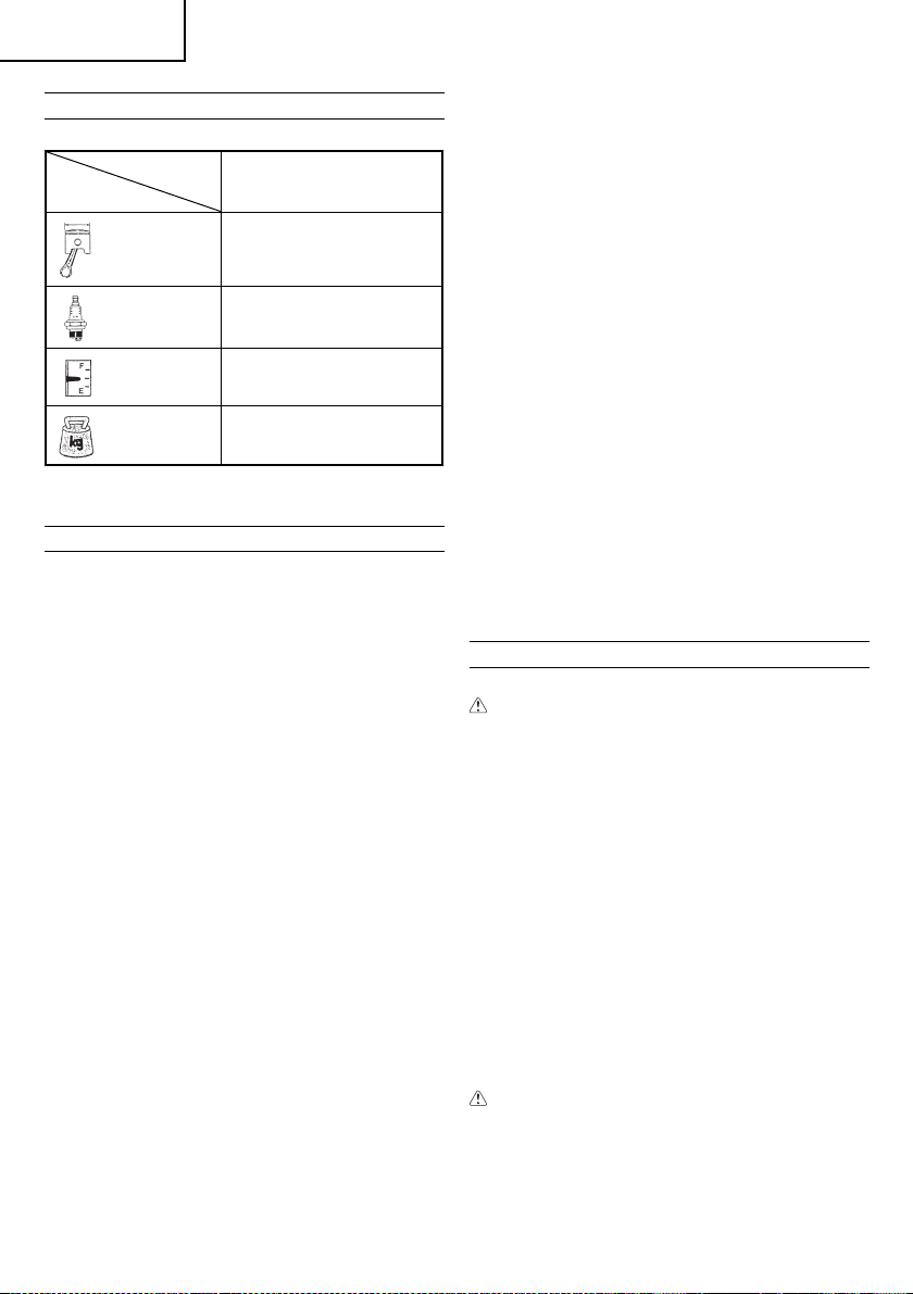
SPECIFICATIONS
Model CG40EBF (L)
Engine Size (ml) 39.8
Spark Plug NGK BPMR6A
Fuel Tank
Capacity (l)
Dry Weight (kg) 9.6
NOTE
* All data is subject to change without notice.
1.2 0
ASSEMBLY PROCEDURES
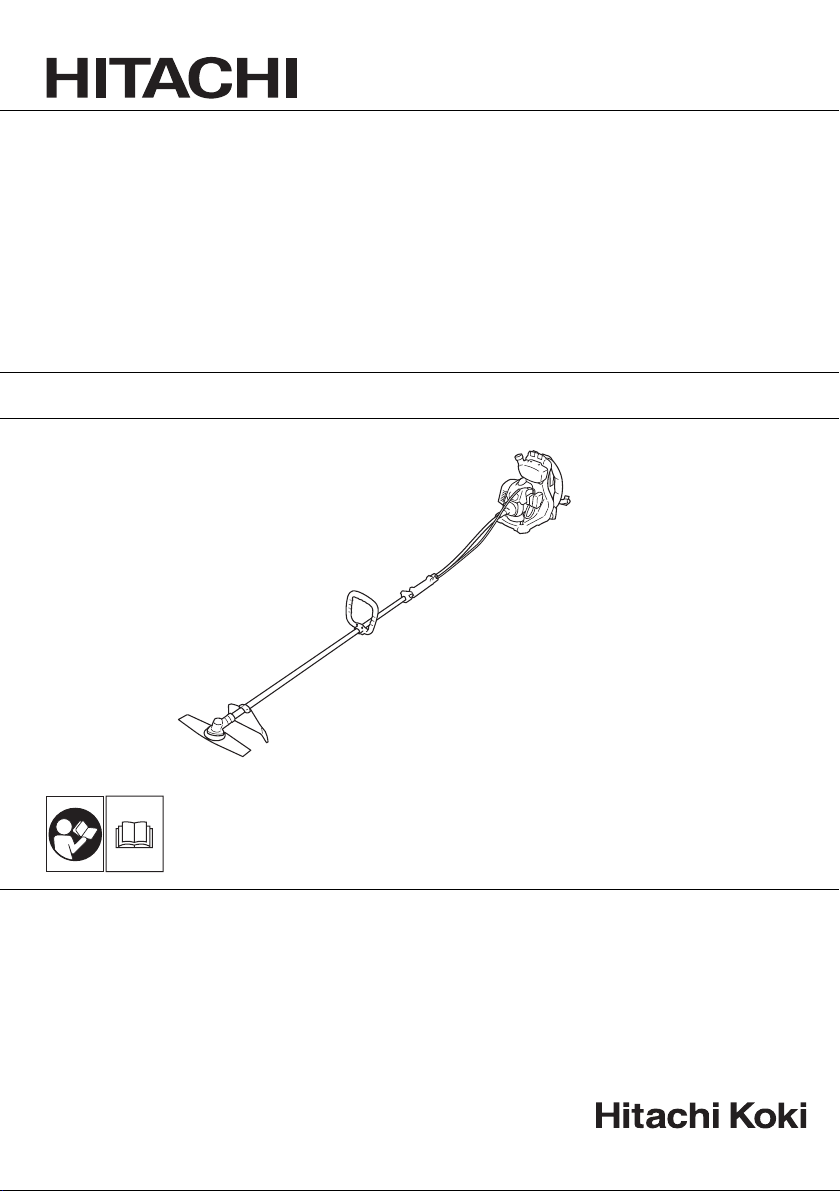
Drive shaft to fl exible shaft (Fig. 1)
Remove joint pipe bolt (1),
Insert the fl exible shaft (2) into the joint pipe (3) of Drive Shaft to the
end and tighten the joint pipe bolt (1) by engaging the bolt to the slot
(4) of fl exible shaft.
NOTE
Make sure to align square end of fl exible inner shaft (5) with
square hole of drive shaft by slightly rotating drive shaft, so that
they are connec ted fi rmly.
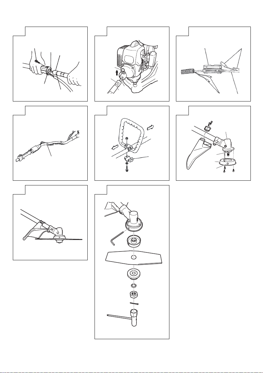
Flexible shaf t to engine (Fig. 2)
Lift fl exible-shaft lock pin (6) .
Insert fl exible shaft (2) into clutch case to the end by inserting
square end of fl exible inner shaft (3) into square hole of adaptor in
clutch case.
Release the lock pin to lock the fl exible shaft by lining up the lock
pin and the hole (7) of fl exible shaft.
Throttle cable and stop cord (Fig. 3)
Connect throttle cables (8) by hooking each cut end of the cables
and clamp the jointed part with connector case (9) which locks.
Connect each end of stop c ords (10).
NOTE
○ When removing connector case, insert coin or minus driver in
slot in th e middle and twist it.
○ Fix protection tube on drive shaft or handle using cord clamps
(11). (Fig. 4)
○ Check that the carburetor throttle returns to the idle position
and also that it can be opened wide by operating the throttle
lever.
Installation of handle (Fig. 5)
Remove the handle bracket (12).
Set the handle on, and attach the handle bracket (12) with two
screws slightly. And adjust position of the handle according to your
working style. Then fi x it fi rmly with the screws.
Installation of blade guard (Fig. 6)
Align the notch hole (14) of the gear case with the hole (15) of the
gear case cover (13) to install the gear case cover with 3 screws.
Install the blade guard on drive shaft tube against angle
transmission (16). Tighten the guard bracket fi rmly so that the blade
guard does not swing or move down during operation.
Install the gear case and blade guard so that blade guard contacts
the gear case. (Fig. 7)
8
CAUTION
The blade guard must be in place when operating.
If the blade guard is not in place when operating, you may get
the serious injury.
Installation of cutting blade (Fig. 8)
When installing a cutting blade, make sure that there are no cracks
or any damage in it and that the cutting edges are facing the correct
direction.
Align the notch hole of the cutter holder with the hole on the gear
case cover and insert the Allen wrench to stop turning. Turn the
fi xing nut clockwise and remove the fi xing nut, cutter holder cap,
and toothed lock washers.
The installation of the cutting blade is as follows: insert the Allen
wrench into the notch hole of the cutter holder and the hole on
the gear case. Then, install the cutting blade (check the installing
direction, as referring to Fig. 10), the cutter holder cap and toothed
lock washers onto the cutter holder in this order. Finally, tighten the
fi xing nut securely by turning counterclockwise with the Combi box
spanner. (Fig. 8)
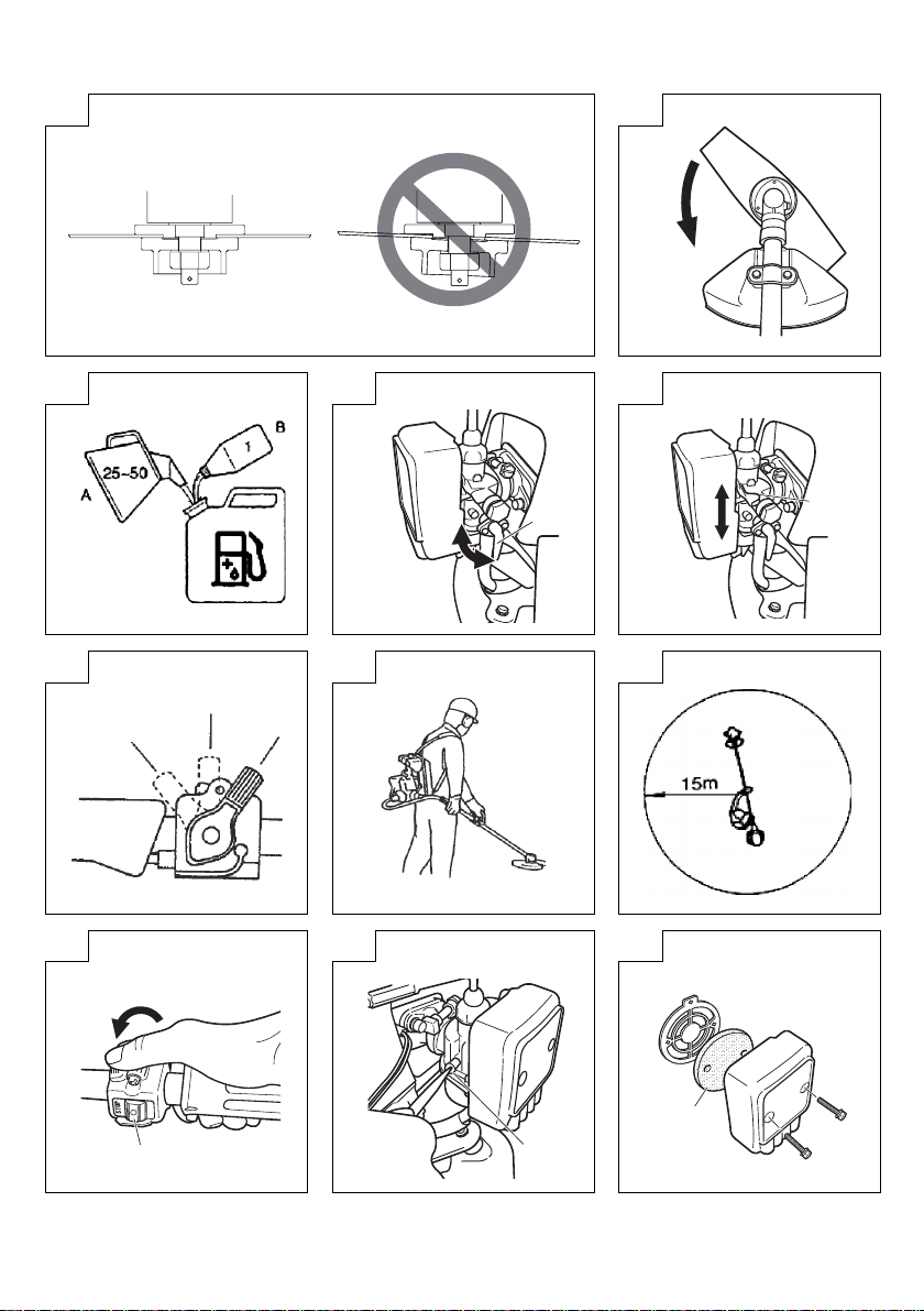
CAUTION
○ When installing the cutting blade, set its center hole to the
convex part of the cutter holder and hold it with the concave
surface of the cutter holder cap. Then, tighten the fi xing nut to
prevent the cutting blade from being eccentric. (Fig. 9)
After installing the cutting blade, be sure to remove the Allen
wrench and Combi box spanner.
○ Before operation, make sure the blade has been properly
installed.
○ Before operation, check the cut ter holder cap under the cutting
blade for wear or cracks. If any damage or wear is found,
replace it, as it is an article of consumption.
NOTE
The blade must be retained with a new cotter pin each time
installed. (Fig. 8)
OPERATING PROCEDURES
Fuel (Fig. 11)
WARNING
○ The backpack brush cutter is equipped with a two-stroke
engine. Always run the engine on fuel, which is mixed with oi l.
Provide good ventilation, when fueling or handling fuel.
○ Fuel is highly fl ammable and toxic and can result in serious
injur y if it is inhaled or comes into contact with your skin. Always
handle fuel with care. Always have good ventilation when
handling fuel inside building.
Fuel
○ Always use branded 89 oct ane unleaded gasoline.
○ Use genuine two -cycle oil or use a mix between 25:1 to 50:1,
please consult the oil bottle for the ratio or Hi tachi dealer.
○ If genuine oil is not available, use an anti-oxidant added qualit y
oil expressly labeled for air-cooled 2-cycle engine use (JASO
FC GRADE OIL or ISO EGC GRADE). Do not use BIA or TCW
(2-stroke water-cooling type) mixed oil.
○ Never use multi-grad e oil (10 W/30) or wa ste oil.
○ Always mix fuel and oil in a separate clean container.
Always start by fi ling half the amount of fuel, which is to be used.
Then add the whole amount of oil. Mix (shake) the fuel mixture. Add
the remaining amount of fuel.
Mix (shake) the fuel-mix thoroughly before fi lling the fuel tank.
Fueling
WARNING
○ Always shut off the engine before refueling.
○ Slowly open the fuel tank, when fi lling up with fuel, so that
possible over-pressure disappears.
○ Tighte n the fuel cap carefully, after fue ling.
○ Always move the backpack brush cutter at least 3 m from the
fueling area before starting.
○ Always wash any spilled fuel from clothing immediately with
soap.
○ Be sure to check for any fuel leakage after refueling.
Page 9

English
Before fueling, clean the tank cap area carefully, to ensure that
no dirt falls into the tank. Make sure that the fuel is well mixed by
shaking the container, before fueling.
Starting
Open the fuel cock (17). (Fig. 12-B)
Move the throttle lever to start p osition A. (Fig. 14)
NOTE
Starting with full throttle causes sudden high revolution of
Blade, which is dangerous, so please avoid it.
Set the choke lever (18) to CLOSED position. (Fig. 13-A)
Pull the recoil starter briskly, TAKING CARE TO KEEP THE
HANDLE in your grasp, while not allowing it to snap back.
When you hear combustible sounds a couple of times, move the
choke lever to OPEN position. Then pull the recoil starter briskly
again.
After starting the engine, allow it about 2 - 3 minutes to warm up
before subjecting it to any load.
CAUTION
Blade may turn and fl exible shaft may swing as engine starts.
Do not let the blade touch any object when engine starts.
After starting the engine, wear the backpack.
Cutting (Fig. 15, 16)
○ When cutting, operate engine at over 6500 min
time of use at low rpm may wear ou t the clutch prematurely.
○ Cut grass from right to left.
○ When working on a slope, the blade should allow the contour
from top to bottom, with th e operator looking down to the left.
○ Blade thrust may occur when the spinning blade contacts a
solid object in the critical area.
A dangerous reaction may occur causing the entire unit and
operator to be thrust violently. This reaction is called blade
thrust. As a result, the operator may lose control of the unit
which may cause serious or fatal injury. Blade thrust is more
likely to occur in areas where it is diffi cult to see the material to
be cut.
○ The blade turns counter-clockwise, therefore, be advised to
operate the unit from right to lef t for effi cient cutting. Keep
onlookers out of working area at least 15 m.
WARNING
○ If the cut ting attachment should strike stones or other debris,
stop the engine and make sure that the attachment and related
parts are undamaged. When grass or vines wrap around
attac hment, stop engine and attachment and remove them.
Stopping (Fig. 17)
Decrease engine speed and run at an idle for a few minutes, then
turn off ignition switch (19).
After stoppin g the engine, close the fuel cock (17). (Fig. 12-A)
WARNING
A cutting attachment can injure while it continues to spin after
the engine is stopped or power control is released. When the
unit is turned off , make sure the cutting attachment has stopped
before the unit is set down.
-1
. Extended
MAINTENANCE
MAINTENANCE, REPLACEMENT OR REPAIR OF THE EMISSION
CONTROL DEVICES AND SYSTEMS MAY BE PERFORMED
BY ANY NON-ROAD ENGINE REPAIR ESTABLISHMENT OR
INDIVIDUAL.
Carburetor adjustment (Fig. 18)
WARNING
○ The cutting attachment may be spinning during carburetor
adjustments.
○ Never start the engine without the complete clutch cover and
tube assembled! Otherwise the clutch can come loose and
cause personal injuries.
In the carburetor, fuel is mixed with air. When the engine is test
run at the factor y, the carburetor is basically adjusted. A further
adjustment may be required, according to climate and altitude. The
carburetor has one adjustment possibility:
T = Idle speed adjustment screw.
Idle speed adjustment (T)
Check that the air fi lter is clean. When the idle speed is correct, the
cutting attachment will not rotate. If adjustment is required, close
(clockwise) the T-screw, with the engine running, until the cutting
attachment starts to rotate. Open (counter-clockwise) the screw
until the cutting attachment stops. You have reached the correct
idle speed when the engine runs smoothly in all positions well
below th e rpm when the cutting attachment starts to rotate.
If the cutting attachment still rotates after idle speed adjustment,
contact your Hitachi dealer.
NOTE
Standard Idle rpm is 2500– 3000 min
WARNING
When the engine is idling the cutting attachment must under no
circumstances rotate.
Air fi lter (Fig. 19)
The air fi lter must be cleaned from dust and dirt in order to avoid:
○ Carburetor malfunctions
○ Starting problems
○ Engine power reduction
○ Unnecessar y wear on the engine parts
○ Abnormal fuel consumption
Clean the air fi lter daily or more often if working in exceptionally
dusty areas.
Cleaning the air fi lter
Remove the air fi lter cover and the fi lter (20). Rinse it in warm soap
suds. Check that the fi lter is dry before reassembly. An air fi lter
that has been used for some time cannot be cleaned completely.
Therefore, it must regularly be replaced with a new one. A damaged
fi lter must always be repl aced.
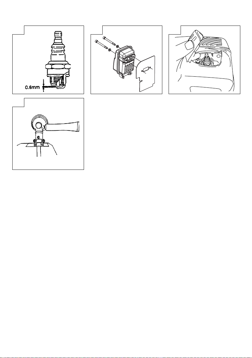
Spark plug (Fig. 20)
The spark plug condition is infl uenced by:
○ An incorrect carburetor setting
○ Wrong fuel mixture (too much oil in the gasoline)
○ A dirt y air fi lter
○ Hard running conditions (such a s cold weather)
These factors cause deposits on the spark plug electrodes, which
may result in malfunction and starting diffi culties. If the engine
is low on power, diffi cult to start or runs poorly at idling speed,
always check the spark plug fi rst. If the spark plug is dirty, clean it
and check the electrode gap. Re-adjust if necessar y. The correct
gap is 0.6 mm. The spark plug should be replaced after about 100
operation hours or earlier if the electrodes are badly eroded.
Muffl er (Fig. 21)
Remove the muffl er and clean out any excess carbon from the
exhaust port or muffl er inlet every 100 hours of operation.
Cylinder (Engine cooling) (Fig. 22)
The engine is air cooled, and air must circulate freely around engine
and over cooling fi ns on cylinder head to prevent overheating.
Every 100 operating hours, or once a year (more often if conditions
require), clean fi ns and external surfaces of engine of dust, dirt and
oil deposits which can contribute to improper cooling.
NOTE
Do not operate engine with engine shroud or muffl er guard
removed as this will cause overheating and engine damage.
Angle transmission (Fig. 23)
Check angle transmission or angle gear for grease level about
every 50 hours of operation by removing the grease fi ller plug on
the side of angle transmission.
If no grease can be seen on the fl anks of the gears, fi ll the
transmission with quality lithium based multipurpose grease up to
3/4. Do not completely fi ll the transmission.
Flexible shaft
When lubricating fl exible shaft, apply grease in the fl exible pipe of
clutch case side. (It is recommended to apply grease after every 1520 hours of use.)
-1
.
9
Page 10

English
Blade
WARNING
○ Use a sharp blade. A dull blade is more likely to snag and
thrust. Replace the fastening nut if it is damaged and hard to
tighten.
○ When replacing blade, purchase one recommended by Hitachi,
with a 25.4 m m (one inch) fi tting hole.
○ When installing a saw blade, always face the stamped side up.
In the case of a 2 tooth blade, it can be used on either side.
○ Use the correct blade for the type of work.
○ When replacin g blades, use appropriate tools.
○ When cutting edges become dull, re-sharpen or fi le as shown
in the illustration. Incorrect sharpening may cause excessive
vibration.
○ Discard blades that are bent, warped, cracked, broken or
damaged in any way.
NOTE
When sharpening blade it is important to maintain an original
shape of radius at the base of the tooth to avoid c racking.
Maintenance schedule
Below you will fi nd some general maintenance instructions. For
further information please contact your Hitachi dealer.
Daily maintenance
○ Clean the exter ior of the unit.
○ Check that the harness is undamaged.
○ Check the blade guard fo r damage or cracks. Change the guard
in case of impacts or cracks.
○ Check that the cut ting attachment is properly centred, sharp,
and without cracks. An off -centre cutting at tachment induces
heavy v ibrations that may damage the unit.
○ Check that the cuttin g attachment nut is suffi ciently tightened.
○ Make sure that the blade transport guard is undamaged and
that it can be securely fi tted.
○ Check that nuts and screws are suffi ciently tightened.
Weekl y maintenance
○ Check the star ter, especially the cord and return spring.
○ Clean the exter ior of the spark plug.
○ Remove it and check the electrode gap. Adjust it to 0.6 mm, or
change the spark plug.
○ Clean the cooling fi ns on the cylinder and check that the air
intake at t he starter is not clogged.
○ Check that the angle gear is fi lled with grease up to 3/4.
○ Clean the air fi lter.
Monthly maintenance
○ Rinse the fuel tank with gasoline.
○ Clean the exter ior of the carburetor and the space around it.
○ Clean the fan and the space around it.
10
Page 11

SIGNIFICADO DE LOS SÍMBOLOS
NOTA: Algunos aparatos no están prov istos de ellos.
Símbolos
ADVERTENCIA
A continuación se muestran lo s símbolos usados para la máquina. Asegúrese de comprender su signifi cado
antes del uso.
Español
Es importante que usted lea, entienda
totalmente y observe las siguientes
precauciones y advertencias de seguridad.
El uso des cuidado o incorrecto del aparato
podrá causarle lesiones serias o fatales.
Lea, comprenda y siga todas las
advertencias y demás instrucciones de
este manual y las q ue se muestran en el
aparato.
Utilice siempre protecciones para los ojos,
la cabeza y los oídos cuando utilice este
aparato.
Haga que los niños, sus ayudantes o
cualquier otr a persona se mantengan a una
distancia de 15 m del aparato. Si alguien
se acerca a usted, detenga el motor y el
mecanismo de corte de inmediato.
min
Muestra la velocidad máxima del eje.
No utilice mecanismos de cor te cuyas
velocidad máximas sean inferiores a
-1
las velo cidad del eje.
Deben utilzarse guantes siempre que
sea necesario, por ejemplo, cuando se
monten equipos de corte.
Utilice calzado antideslizante y
resistente.
Puede producirse una sacudida
de la cuchilla si al encontrarse en
movimiento ésta entra en contacto
con un objeto sólido en la zona crítica.
Puede producirse una reacción
peligrosa que sacuda violentamente el
aparato y al usuario. Esta reacción se
conoce como sacudida de la cuchilla.
Como consecuencia , el usuario
podría perder e l control de la unidad
y ocasionar lesiones graves e incluso
mortales. E xisten más probabilidades
de que se produzcan sacudidas de la
cuchilla en zonas en las que es difícil
ver el material que se está cortando.
Tenga cuidado con los objeto s que puedan
salir despedidos.
Contenido
¿QUÉ ES QUÉ? ...............................................................................12
ADVERTENCIAS E INSTRUCCIONES DE SEGURIDAD ..............13
ESPECIFI CACIONES ...................................................................... 14
PROCEDIMIENTOS DE M ONTAJE ................................................14
PROCEDIMIENTOS DE OPERACIÓN ............................................15
MANTENI MI ENTO ........................................................................... 15
11
Page 12

Español
¿QU É ES QUÉ?
Puesto que este manual cubre varios modelos, puede que existan
diferencias entre los dibujos y su unidad. Utilice las instrucciones
que se refi eran a su unidad.
1. Tapa del depósito de combustible
2. Mango del acelerador
3. Llave de ignición
4. Protector de la cuchilla
5. Mecanismo de cor te
6. Eje de transmisión
7. A s i d e ro
8. Arnés
9. Carcasa del embrague
10. Mango del arrancador
11. Llave de combustible
12. Palanca del estárter
13. Motor
14. Transmisión en ángulo
15. Llave combinada de cubo
16. Instr ucciones de manejo
514
6
4
2
7
12
1
13
9
15
3
16
8
11
10
12
Page 13

Español
ADVERTENCIAS E INSTRUCCIONES DE
SEGURIDAD
Seguridad del usuario
○ Utilice siempre protecciones como caretas o gafas de
seguridad.
○ Utilice siempre pantalones largos, botas y guantes de tejidos
resistentes. No utilice prendas sueltas, joyas, pantalones
cortos o sandalias, y nunca trabaje descalzo. Recójase el pelo
de forma que quede por enc ima del hombro.
○ No opere este aparato si está cansado, enfermo o bajo la
infl uencia del alcohol, drogas o medicamentos.
○ No deje qu e niños o person as inexpertas operen el aparato.
○ Utilice protección para los oídos. Preste atención a su entorno.
Esté atento a personas que pudieran estar avisándole de un
problema. Quítese el equipo de seguridad inmediatamente
después de detener el motor.
○ Utilice casco protector.
○ Nunca encienda el motor o haga funcionar el aparato dentro de
una sala cerrada o un edifi cio. La inhalación de los gases de
escape puede ser mortal.
○ Mantenga los asideros libres de aceite y combustible.
○ Mantenga las manos alejadas del equipo de cor te.
○ No agarre o sostenga el aparato por el equipo de cor te.
○ Cuando el aparato esté apagado, asegúrese de que el
mecanismo de corte se ha detenido antes de apoyarlo sobre el
suelo.
○ Durante periodos de operación prolongados, se recomienda
descansar de vez en cuando para evitar el posible síndrome
de vibración de manos y brazos (HAVS) causado por las
vibraciones.
ADVERTENCIA
○ Los sistemas antivibratorios no garantizan que pudiera verse
afectado por síndrome de vibración de manos y brazos o el
síndrome del túnel carpiano. Por lo tanto, los usuarios que
utilicen el aparato asiduamente o con regularidad deberán
vigilar con atención el estado de sus manos y dedos. Si
aparece cualquiera de los síntomas citados, deberá acudirse a
un médico de inmediato.
○ Si utiliza algún dispositivo médico eléctrico o electrónico,
como por ejemplo un marcapasos, consulte a su médico y al
fabricante del dispositivo antes de operar cualquier equipo
motorizado.
Seguridad del aparato
○ Inspeccione siempre el aparato antes de utilizarlo.
Reemplace las piezas dañadas. Compruebe que no hay
fugas de combustible y asegúrese de que todas las piezas se
encuentran en su sitio y han sido apretadas cor rectamente.
○ Reemplace cualquier pieza agrietada, rota o deteriorada antes
de poner en march a el aparato.
○ Asegúrese de que la protección de seguridad está acoplada
correctamente.
○ No permita que se acerquen personas mientras ajusta el
carburador.
○ Utilice únicamente los accesorios que el fabricante recomiende
para este dispositivo.
ADVERTENCIA
No intente modifi car el aparato en forma alguna. No utilice este
aparato para otras tareas para las que no esté indicado.
Seguridad del combustible
○ Mezcle y llene el combustible al aire libre, en lugares donde no
se produzcan chispas ni llamas.
○ Utilice un recipiente homologado para combustible.
○ No fume ni deje fumar a otras personas en las proximidades
del combustible o del aparato mientras éste se encuentre en
marcha.
○ Limpie los restos de combustible antes de arrancar el m otor.
○ Antes de arrancar el motor, desplácese al menos 3 metros
respecto del lu gar en el que ha llenado el combustible.
○ Detenga el motor antes de quitar la tapa del depósito de
combustible.
○ Vacíe el depósito de combustible antes de guardar el aparato.
Se recomienda vaciar el depósito de combustible cada vez
que termine de utilizar el aparato. Si deja combustible en el
depósito, asegúrese de que no van a producirse escapes.
○ Guarde el aparato y el combustible en un lugar donde los
vapores del combustible no puedan entrar en contacto con
chispas o llamas de calentadores de agua, motores eléctricos,
interruptores, hornos, etc.
ADVERTENCIA
El combustible puede infl amarse, explotar o emitir gases con
facilidad. Por lo tanto, debe prestar especial atención cuando
manipule o recargue el combustible.
Seguridad durante el corte
○ No corte ningún material que no sea hierba o maleza.
○ No realice operaciones que puedan dar lugar a un fuerte
impacto en el accesorio de cor te.
Si no se cumple esta indicació n el eje podría resultar dañado.
○ Inspeccione siempre la zona sobre la que va a cortar antes de
comenzar. Retire cualquier objeto que pueda salir despedido o
enredarse.
○ Para proteger las vías respiratorias, utilice una máscara de
protección contra aerosoles cuando corte hierba tras haber
fumigado con insecticidas.
○ Mantenga a otras personas, niños, animales y ayudantes
a una distancia de 15 m de la zona de riesgo. Detenga
inmediatamente el motor si se le acerca alguna persona.
○ Mantenga el eje de transmisión en el lado derecho respecto de
su cuerpo en todo momento.
○ Sostenga el aparato fi rmemente con ambas manos.
○ Apoye sus pies con fi rmeza y mantenga el equilibrio. No estire
demasiado el cuerpo.
○ Mantenga su cuerpo apar tado del silenciador y del mecanismo
de corte mientras el motor se encuentra en marc ha.
○ Mantenga el mecanismo de corte por debajo del nivel de la
cintura.
○ Cuando cambie de zona de trabajo, asegúrese de detener el
aparato y de que el mecanismo de corte se ha detenido.
○ Nunca deposite el aparato sobre el suelo mientras éste se
encuentra en marcha.
○ Asegúrese siempre de que el motor está apagado y de que
el mecanismo de corte se ha detenido por completo antes de
eliminar resi duos o hierba del mecan ismo de corte.
○ Lleve siempre un botiquín de primeros auxilios consigo cuando
opere cualquier equipo motorizado.
○ Nunca encienda el motor o haga funcionar el aparato dentro de
una sala cerrada o un edifi cio o en las proximidades de líquidos
infl amables. La inhalación de los gases de escape puede ser
mortal.
Seguridad durante el mantenimiento
○ Realice el mantenimiento del aparato siguiendo los
procedimientos recomendados.
○ Antes de realizar el mantenimiento, desconecte la bujía (salvo
si va a ajustar el carburador).
○ No permita que se acerquen personas mientras ajusta el
carburador.
○ Utilice únicamente los repuestos y accesorios originales de
Hitachi recomendados.
Transporte y almacenamiento
○ Transporte el aparato con el motor y el silenciador a una
distancia segura del cuerpo.
○ Antes de almacenar o transportar el aparato en un vehículo,
espere a que se haya enfriado el motor, vacíe el depósito de
combustible y asegúrelo correctamente.
○ Vacíe el depósito de combustible antes de guardar el aparato.
Se recomienda vaciar el depósito de combustible cada vez
que termine de utilizar el aparato. Si deja combustible en el
depósito, asegúrese de que no van a producirse escapes.
○ Guarde el aparato lejos d el alcance de niños.
○ Limpie y lleve a cabo el mantenimiento del aparato con cuidado
y guárdelo en un lugar seco.
○ Asegúrese de que la llave de encendido del motor esté
desconectada cuando transporte o guarde el aparato.
○ Cuando transporte el aparato en un vehículo o lo guarde, cubra
la cuchilla con una cubierta.
13
Page 14

Español
Si se producen situaciones no previstas en este manual, utilice el
sentido común. Póngase en contacto con su distribuidor de Hitachi
si necesita ayuda. Dedique especial atención a los apartados
introducidos por las siguientes palabras:
ADVERTENCIA
Indica un riesgo signifi cativo de que se produzcan daños
personales graves e incluso la muerte si no se siguen las
instrucciones.
PRECAUCIÓN
Indica la posibilidad de que se produzcan daños personales o
materiales si no se siguen las instrucciones.
NOTA
Indica información útil para el uso y correcto funcionamiento
del aparato.
PRECAUCIÓN
No desmonte el arrancador de retroceso. El resorte del
arrancador puede ocasionarle lesiones personales graves.
ESPECIFICACIONES
Modelo CG40EBF (L)
Tamaño del motor
(ml)
Bujía NGK BPMR6A
Capacidad del
depósito de
combustible (l)
Peso en seco (kg) 9,6
NOTA
* Todos los datos están sujeto s a cambios sin previo aviso.
39,8
1,2 0
PROCEDIMIENTOS DE MONTAJE
Eje de distribución a eje fl exible (Fig. 1)
Retire el tornillo del tubo conector (1),
introduzca completamente el eje fl exible (2) en el tubo conector
(3) del eje de distribución y apriete el tornillo del tubo conector (1)
encajando el tornill o en la ranura (4) del eje fl exible.
NOTA
Asegúrese de confrontar el ex tremo cuadrado del eje interior
fl exible (5) con el orifi cio cuadrado del eje de distribución
girando ligeramente el eje de distribución, de modo que
queden fi rmemente conectados.
Eje fl exible a motor (Fig. 2)
Levante el pasador de bloqueo del eje fl exible (6).
Introduzca completamente el eje fl exible (2) en la carcasa del
embrague introduciendo el extremo cuadrado del eje interior
fl exible (3) en el orifi cio cuadrado del adaptador de la carcasa del
embrague.
Libere el pasador de bloqueo para bloquear el eje fl exible haciendo
coincidir el pasador de bloqueo y el orifi cio (7) del eje fl exible.
Cable de aceleración y cordón de parada (Fig. 3)
Conectar los cables de aceleración (8) enganchando todos los
extremos cor tados de los cables y apretar la parte unida con la caja
del conector (9) que se bloquea. Conectar todos los extremos de
los cordones de parada (10).
NOTA
○ Al quitar la caja de conectores, insértese una moneda o un
atomillador con punta derecha en la ranura del medio y hagase
girar.
○ Fijar tubo de proteccion en maneja shaft o handle que utilizan
abraz aderas de cuerda (11). (Fig. 4)
○ Asegúrese de que el acelerador del carburador vuelve a la
posición de ralentí y que se puede abrirse completamente
mediante la palanca del acelerador.
Instalación del asidero (Fig. 5)
Retire la abrazadera del asidero (12).
Coloque el asidero y acople la abrazadera del asidero (12)
ajustándola suavemente con dos tornillos. Ajuste la abrazadera en
la posición adecuada. A continuación apriétela con los tor nillos.
Instalación del protector de la cuchilla (Fig. 6)
Alinee el orifi cio de la entalladura (14) de la cubier ta del engranaje
con el orifi cio (15) de la tapa de la cubierta del engranaje (13) para
instalar la cubierta del engranaje con 3 tornillo s.
Acople l a cubierta del engranaje con los tres tornillos.
Instale el protector de la cuchilla en el tubo del eje de distribución
y contra la transmisión en ángulo (16). Ajuste fi rmemente la
abrazadera del protector de manera que el protector de la
cuchilla no se mueva hacia los lados o hacia abajo durante el
funcionamiento del aparato.
Instale el engranaje y el protector de la cuchilla de modo que el
protector de la cuchilla entre en contacto con el engranaje. (Fig. 7)
PRECAUCIÓN
El protector de la cuchilla debe estar bien instalado durante la
operación.
Si el protector de la cuchilla no estuviera bien instalado durante
la operación, p odría sufrir una lesión grave.
Instalación de la cuchilla cortante (Fig. 8)
Cuando instale una cuchilla, asegúrese de que no presenta
grietas o daños y de que los fi los cor tantes apuntan en la dirección
correcta.
Confronte el agujero de la entalladura del soporte de la cuchilla
con el agujero en la cubierta del engranaje (parte superior del
engranaje) e inserte la llave Allen para evitar que gire. Gire la tuerca
de fi jación hacia la derecha y retire la tuerca de fi jación, la tapa del
sopor te de la cuchill a y los cierres de tuerca dentados.
Instale la cuchilla cortante de la siguiente manera: Inserte la llave
Allen en el agujero de la entalladura del sopor te de la cuchilla y
en el agujero del engranaje. A continuación, instale la cuchilla
cortante (compruebe la dirección de instalación, como se indica en
la Fig. 10), la tapa del soporte de la cuchilla y los cierres de tuerca
dentados en el soporte de la cuchilla en este orden. Por último,
apriete bien la tuerca de fi jación girándola hacia la izquierda con la
llave combinada de cubo. (Fig. 8)
PRECAUCIÓN
○ Cuando instale la cuchilla cortante, coloque el agujero central
en la parte convexa del soporte de la cuchilla y asegúrelo a la
superfi cie cóncava de la tapa del sopor te de la cuchilla. Luego
apriete la tuerca de fi jación para evitar que la cuchilla cortante
se descentre. (Fig. 9)
Tras instalar la cuchilla cortante, asegúrese de retirar la llave
Allen y la llave com binada de cubo.
○ Antes de poner el aparato en funcionamiento, asegúrese de
que la cuchilla se ha instalado correctamente.
○ Antes de poner el aparato en funcionamiento, compruebe
que la tapa del soporte de la cuchilla ubicada bajo la cuchilla
no esté gastada o rota. Si se encuentra algún daño o rotura,
deberá sustituirla, ya que se trata de un artíc ulo consumible.
NOTA
La cuchilla debe sujetarse con un pasador nuevo cada vez que
se instale. (Fig. 8)
14
Page 15

Español
PROCEDIMIENTOS DE OPERACIÓN
Combustible (Fig. 11)
ADVERTENCIA
○ La desbrozadora de mochila está equipada con un motor de
dos tiempos. El motor debe funcionar siempre con combustible
mezclado con aceite.
Asegúrese siempre de que existe una buena ventilación en los
lugares de manipulación o recarga del combustible.
○ El combustible es altamente infl amable y tóxico y puede
ocasionar lesiones graves si se inhala o entra en contacto con
la piel. E xtreme el cuidado cuando maneje el combustible.
Asegure siempre una buena ventilación cuando maneje el
combustible dentro d e un edifi cio.
Combustible
○ Utilice siempre gasolina sin plomo de marca de 89 octanos.
○ Utilice el aceite de dos tiempos del fabricante original o utilice
una mezcla en proporciones de 25:1 a 50:1. Consulte el
recipiente o a un distribuidor Hitachi para obtener la proporción
de aceite correcta.
○ Si no es posible obtener el aceite del fabricante original, utilice
un aceite con antioxidantes de calidad que esté expresamente
indicado para motores de dos tiempos refrigerados por aire
(JASO FC GRADE OIL o ISO EGC GRADE). No utilice aceite
mezclado BIA o TCW (para 2 tiem pos refrigerado por ag ua).
○ No utilice nunca aceites para distintas temperaturas (10 W/30)
ni aceites usados.
○ Mezcle siempre el combustible y el aceite en un recipiente
limpio y destinado a este fi n.
Comience siempre por llenar la mitad del combustible que va
a utilizar. Luego, agregue todo el aceite. Agite la mezcla de
combustible. Añada el resto de la gasolina.
Antes de llenar el depósito de combustible, agi te bien la mezcla .
Recarga de combustible
ADVERTENCIA
○ Apague siempre el motor antes de recargar el combustible.
○ Para llenar el depósito de combustible, abra lentamente la
tapa del depósito para que desaparezca la sobrepresión que
pudiera existir.
○ Después de llenarlo, cierre y apriete bien la tapa.
○ Antes de arrancar la desbrozadora de mochila, deberá alejarse
al menos 3 m del área de recarga de combustible.
○ Lave siempre inmediat amente con jabón cualquier combustible
verti do sobre la ropa.
○ Asegúrese de verifi car si existe alguna fuga de combustible
después del llenado.
Antes de llenar el combustible, limpie cuidadosamente la zona
de la tapa del depósito para garantizar que no entra suciedad en
el depósito. Asegúrese de que el combustible está bien mezclado
agitando el recipiente antes de llenar el depósito.
Arranque
Abra la llave de combustible (17). (Fig. 12-B)
Mueva el mango del acelerador a la posición A de funcionamiento.
(Fig. 14)
NOTA
Si arranca habiendo girado completamente el acelerador, la
cuchilla comenzará a girar a gran velocidad de repente, lo que
resulta peligroso y debe evitarse.
Lleve la palanca del estárter (18) a la posición CLOSED (cerrado).
(Fig. 13-A)
Tire enérgicamente del arrancador de retroceso. TOME LA
PRECAUCIÓN DE MANTENER EL ASIDERO bien sujeto para
evitar que se escape de la mano.
Cuando escuche el amago de arranque del motor, devuelva la
palanca del estárter a la posición OPEN (abier to). A continuación
vuelva a tirar en érgicamente del arrancador de retroceso.
Una vez encendido el motor, deje que se caliente durante 2-3
minuto s antes de someterlo a ninguna presión.
PRECAUCIÓN
La cuchilla puede girar y el eje fl exible puede moverse hacia
los lados cuando arranque el motor. No permita que la cuchilla
toque ningún objeto al ar rancar el motor.
Tras arrancar el motor, colóquese la mochila.
Corte (Fig. 15, 16)
○ Cuando corte, haga funcionar el motor a más de 6500 min
utilización prolongada a pocas rpm podría dañar el embrague
prematuramente.
○ Corte la hierba de derecha a izqu ierda.
○ Si trabaja en pendiente, la cuchilla debe permitir que el
contorno suba y baje, con el usuario mirando hacia abajo y
hacia la izquierda.
○ Puede producirse una sacudida de la cuchilla si al encontrarse
en movimiento ésta entra en contacto con un objeto sólido en la
zona crítica.
Puede producirse una reacción peligrosa que sacuda
violentamente el aparato y al usuario. Esta reacción se conoce
como sacudida de la cuchilla. Como consecuencia, el usuario
podría perder el control de la unidad y provocarse lesiones
graves e incluso mortales. Existen más probabilidades de que
se produzcan sacudidas de la cuchilla en zonas en las que es
difíci l ver el material que se está cort ando.
○ La cuchilla gira en sentido contrario a las agujas del reloj. Por
tanto, para una mayor efi cacia de corte, proceda siempre de
derecha a izquierda. Haga que cualquier persona se sitúe a
una distancia de al menos 15 m.
ADVERTENCIA
○ Si el mecanismo de corte choca contra piedras u otros
obstáculos, detenga el motor y asegúrese de que el
mecanismo de corte y las piezas asociadas se encuentran
en buen estado. Cuando se enreden hierba o ramas en el
mecanismo, detenga el motor y el mecanismo y retírelas antes
de continuar.
Parada (Fig. 17)
Reduzca la velocidad del motor y déjelo permanecer al ralentí
durante unos minutos. A continuación apague la llave de ignición
(19).
Tras detener el motor, cierre la llave de combustible (17). (Fig. 12-
A)
ADVERTENCIA
El mecanismo de corte puede provocar lesiones mientras gira
tras haber detenido el motor o haber apagado el control de la
alimentación. Cuando el aparato esté apagado, asegúrese de
que el mecanismo de corte se ha detenido antes de apoyarlo
sobre el suelo.
-1
. La
MANTENIMIENTO
EL MANTENIMIENTO, SUSTITUCIÓN O REPARACIÓN DE LOS
DISPOSITIVOS Y SISTEMAS DE CONTROL DE EMISIONES
PUEDEN REALIZARSE EN CUALQUIER TALLER O A CARGO DE
CUALQUIER TÉCNICO DE REPARACIONES MECÁNICAS NO
DESTINADAS AL TRANSPORTE .
Ajuste del carburador (Fig. 18)
ADVERTENCIA
○ El mecanismo de cor te podría estar girando mientras ajusta el
carburador.
○ Nunca arranque el motor sin que la cubierta y el tubo del
embrague estén montados. De lo contrario, el embrague podría
soltarse y provocar lesiones personales.
En el carburador, el combustible se mezcla con aire. El carburador
se ajusta durante la prueba del motor en la fábrica. Sin embargo,
puede que sea necesario reajustarlo con arreglo al clima y a la
altitud. El carburador tiene una opción de ajuste:
T = Tornillo de ajuste de la velocidad de ralentí.
15
Page 16

Español
Ajuste de la velocidad de ralentí (T)
Compruebe que el fi ltro de aire está limpio. Cuando la velocidad
de ralentí sea la correcta, el mecanismo de corte no girará. Si es
necesario ajustarlo, cierre el tornillo T (en el sentido de las agujas
del reloj) con el motor en marcha hasta que el mecanismo de
corte empiece a girar. Abra el tornillo T (en el sentido contrario a
las agujas del reloj) hasta que el mecanismo de corte se detenga.
Habrá obtenido la velocidad de ralentí correcta cuando el motor
funcione con suavidad en cualquier posición encontrándose muy
por debajo de las rpm necesarias para que el mecanismo de corte
empiece a girar.
Si el mecanismo de corte sigue girando tras ajustar la velocidad de
ralentí, póngase en contacto con un distribuidor Hitachi.
NOTA
Las rpm normales al ralentí se encuentran entre las 2500–3000
-1
.
min
ADVERTENCIA
Mientras el motor está al ralentí, el mecanismo de corte no
debería girar en ningún caso.
Filtro de aire (Fig. 19)
Limpie el polvo y la suciedad del fi ltro de aire para evitar:
○ Fallos de funcionamie nto del carburador
○ Problemas de arranque
○ Pérdidas de potencia
○ Desgaste inne cesario de las piezas del motor
○ Consumo excesivo de combustible
Limpie el fi ltro de aire diariamente o con mayor frecuencia cuando
trabaje en zonas con gran cantidad de polvo.
Limpieza del fi ltro de aire
Extraiga la cubierta del fi ltro de aire y el fi ltro (20). Lave los
fi ltros con agua caliente y jabón. Antes de volver a montar el
fi ltro, compruebe que éste esté seco. Un fi ltro de aire que ha
sido utilizado durante mucho tiempo, nunca podrá quedar
completamente limpio. Por tanto, los fi ltros deben reemplazarse
por otros nuevos en intervalos regulares. Reemplace los fi ltros que
estén dañados.
Bujía (Fig. 20)
El estado de la bujía se ve afec tado por:
○ Mal ajuste del carburador
○ Mezcla incorrecta de combustible y aceite (exceso de aceite en
la gasolina)
○ Suciedad en el fi ltro de aire
○ Condiciones de funcionamiento extremas (por ejemplo climas
fríos)
Todos estos factores dan lugar a la formación de sedimentos en
los electrodos, los cuales pueden provocar perturbaciones en el
funcionamiento y difi cultades en el arranque. Si el motor tiene poca
potencia, tiene difi cultades para arrancar el aparato o el ralentí se
muestra inestable, verifi que siempre la bujía en primer lugar. Si
la bujía está muy sucia, límpiela y verifi que la distancia entre los
electrodos. Reajústela si es necesario. La distancia correcta es
de 0,6 mm. Se debe reemplazar la bujía tras unas 100 horas de
funcionamiento o antes si los electrodos están muy gastados.
Silenciador (Fig. 21)
Quite el silenciador y limpie cualquier exceso de carbono de la
salida del escape o la entrada del silenciador cada 100 horas de
funcionamiento.
Cilindro (refrigeración del motor) (Fig. 22)
El motor se refrigera por aire. Por tanto, el aire debe circular
libremente en torno al motor y las aletas de refrigeración del
cabezal del cilindro para evitar que se sobrecalienten.
Cada 100 horas de funcionamiento, o una vez al año (o con más
frecuencia cuando sea necesario), limpie las aletas y la superfi cie
exterior del motor, eliminando los sedimentos de polvo, la suciedad
y el aceite que pudieran obstaculizar una refrigeración adecuada .
NOTA
No haga funcionar el motor sin el carenaje o el protector del
silenciador, ya que esto podría causar un sobrecalentamiento y
provocar daños en el motor.
16
Transmisión en ángulo (Fig. 23)
Compruebe el nivel de lubricante de la transmisión o el engranaje
en ángulo cada 50 horas de funcionamiento extrayendo el tapón
del depósito de lubric ante del lateral de la transmisión en ángulo.
Si no se aprecia lubricante en los fl ancos de los engranajes, llene la
transmisión a 3/4 con lubricante universal de litio de buena calidad.
No llene la transmisión por completo.
Eje fl exible
Al lubricar el eje fl exible, aplique lubricante en el tubo fl exible
del lado de la carcasa del embrague. (Se recomienda aplicar
lubricante cada 15-20 horas de uso).
Cuchilla
ADVERTENCIA
○ Utilice una cuchilla afi lada. Una cuchilla roma presenta
más probabilidades de atacarse y dar sacudidas. Sustituya
la tuerca de ajuste si se encuentra dañada o encuentra
difi cultades al apretarla.
○ Cuando sustituya la cuchilla, adquiera una que esté
recomendada por Hitachi y equipada con un orifi cio de 25,4
mm (1 plg).
○ Cuando instale un disco de corte, coloque siempre la parte
impresa hacia arriba. En el caso de las cuchillas de 2 dientes,
pueden colocarse en ambas direcciones.
○ Utilice la cuchilla correcta para cada tipo de trabajo.
○ Cuando sustituya las cuchillas, utilice las herramientas
adecuadas.
○ Cuando los fi los se emboten, afílelos o límelos tal y como se
muestra en la ilustración. Un afi lado incorrecto podría provocar
vibraciones excesivas.
○ Deseche cualquier cuchilla doblada, combada, agrietada, rota
o dañada de cualquier otra forma.
NOTA
Cuando afi le las cuchillas es importante mantener la forma
original del radio en la base de los dientes para evitar
agrietamientos.
Esquema de mantenimiento
A continuación se proporcionan algunas instrucciones generales
de mantenimiento. Para obtener información adicional, póngase en
contacto con un distribuidor de Hitachi.
Mantenimiento diario
○ Limpie el exterior del aparato.
○ Compruebe que el arnés se encuentra en buen estado.
○ Compruebe que no existen daños o grietas en el protector de la
cuchilla. En caso de impactos o grieta s, sustituya el protector.
○ Compruebe que el mecanismo de corte está debidamente
centrado, afi lado y libre de grietas. Si el mecanismo de corte
no está centrado, puede provocar fuertes vibraciones y dañar
el aparato.
○ Compruebe que la tuerca del mecanismo de corte está
sufi cientemente apretada.
○ Aseg úrese de qu e la protec ción para el tra nsporte de la cuchi lla
no está dañada y puede fi jarse con fi rmeza.
○ Comp ruebe que la s tuercas y los t ornillos es tán sufi cientemente
apretados.
Mantenimiento semanal
○ Compruebe el sistema de arranque, en especial la cuerda y el
muelle de retroceso.
○ Limpie el exterior de la bujía.
○ Extraiga la bujía y compruebe la distancia entre los electrodos.
Ajústela hast a 0,6 mm o sustituya la bujía.
○ Limpie las aletas de refrigeración del cilindro y compruebe que
la admisión de aire no se encuentra obstruida.
○ Compruebe que el engranaje en á ngulo está lleno de lubricante
a 3/4 de su capacidad.
○ Limpie el fi ltro de aire.
Mantenimiento mensual
○ Lave el depósito de combustible con gasolina.
○ Limpie el exter ior del carbur ador y los alrededores del mismo.
○ Limpie el ventilador y sus alred edores.
Page 17

SIGNIFICADO DOS SÍMBOLOS
NOTA: Os símbolos referidos não se encontram em todos os
modelos.
Símbolos
ADVERTÊNCIA
A seguir aparec em os símbolos utilizados pela máquina. Assimile bem seus signifi cado s antes do uso.
É impor tante que você leia, compreenda
integralmente e obser ve as seguintes
precauções e advertências de segurança .
O uso descuidado ou incorreto da
ferram enta pode caus ar lesões graves ou
até fatais.
min
Mostra a velocidade má xima do eixo.
Não use um m ecanismo de corte com
-1
velocidade má ximas inferiores às
velocidade do eixo.
Português
Leia, compreenda e siga todas as
advertências e instruçõe s contidas neste
manual e na ferra menta.
Sempre use protetores pa ra os olhos,
cabeça e ouvidos durante o uso desta
ferramenta.
Mantenha todas as crianças, curiosos
e ajudantes a 15 metro s de distância da
ferram enta. Se alguém se aprox imar, pare
imediatamente o motor e o mecani smo
de corte.
Tome cuidado com objetos arremessados.
Sumário
DESCRIÇÃO DE CADA COMPONENTE ........................................18
ADVERTÊNCIAS E INSTRUÇÕES DE SEGURANÇA ...................19
ESPECIFI CAÇÕE S ..........................................................................20
PROCEDIMENTOS DE MONTAGEM .............................................20
PROCEDIMENTOS DE OPERAÇÃO ..............................................20
MANUTENÇÃO ...............................................................................21
Você deve usar luvas quando
necessário, p or exemplo, ao mont ar o
equipamento de corte.
Use calçados robustos e
antiderrapantes.
Pode gerar-se uma força de
compressão na lâmina se a lâmin a
em rotaç ão entrar em contato com um
objeto sólido na área crítica. Isso, por
sua vez, pode provocar uma reação
perigosa na forma de um contra-golpe
violento na ferramenta e no operador.
Esta reação é denominada contragolpe da lâmina. Em conseqüên cia,
o operador pode perder o c ontrole
da ferra menta, o que pode causa r
ferime ntos graves ou fatais. O
contra-golpe da lâmina tem maior
probabilidade de ocorrência onde é
difícil ver o material a ser cortado.
17
Page 18

Português
DESCRIÇÃO DE CADA COMPONENTE
Como este manual cobre vários modelos, podem existir algumas
diferenças entre as ilustrações e a sua ferramenta. Use as
instruções que se aplicam à sua ferramenta.
1. Tampa do tanque de combustível
2. Alavanca do acelerador
3. Interruptor de ignição
4. Protetor da lâmina
5. Mecanismo de cor te
6. Tubo do eixo de transmissão
7. C a b o
8. Alça
9 Caixa da em breagem
10. Cabo de arranque
11. Torneira do combustível
12. Alavanca do afogador
13. Motor
14. Transmissão angular
15. Chave combinada
16. Manual de instruçõe s
514
7
6
4
2
12
1
13
9
15
3
16
8
11
10
18
Page 19

Português
ADVERTÊNCIAS E INSTRUÇÕES DE
SEGURANÇA
Segurança do operador
○ Sempre use uma máscara ou óculos de proteção.
○ Sempre use calças pesadas e compridas, botas e luvas. Não
use roupas folgadas, jóias e bijuteria, calções, sandálias e
nunca trabalhe descalço. Prenda o cabelo para que ele não
caia por cima dos ombros.
○ Não use esta ferramenta quando estiver cansado, doente ou
sob efeitos de álcool, drogas ou m edicamentos.
○ Nunca deixe uma criança ou uma pessoa inexperiente operar
esta ferramenta.
○ Use uma proteção para os ouvidos. Preste atenção ao
arredores. Fique atento a quaisquer observadores que
possam apresentar algum problema. Retire o equipamento de
segurança imediatamente depois de apagar o motor.
○ Use um capacete.
○ Nunca arranque nem deixe o motor funcionando no interior de
um quarto ou prédio. A inalação dos gases de escape pode
provocar a morte.
○ Mantenha os cabos livres de óleo e gasolina.
○ Mantenha as mãos afastadas do mecanismo de corte.
○ Não agar re nem segure a ferramenta pelo mecanismo de corte.
○ Depois de desligar a ferramenta, certifi que-se de que o
mecanismo de corte tenha parado antes de deixá-la em algum
lugar.
○ Durante trabalhos prolongados, faça pausas de vez em quando
para prevenir a síndrome de vibração das mãos e braços
(HAVS) causada pela vibração.
ADVERTÊNCIA
○ Sistemas anti-vibratórios não garantem que o operador não
sofra da síndrome de vibração das mãos e braços ou da
síndrome do túnel cardal. Portanto, os usuários freqüentes
e contínuos devem estar sempre atentos ao estado das suas
mãos e dedos. Se você perceber qualquer um dos sintomas
mencionados acima, consulte um médico imediatamente.
○ Se você estiver usando um dispositivo médico elétrico/
eletrônico como, por exemplo, um marcapasso, consulte o
seu médico e o fabricante do aparelho antes de trabalhar com
equipamentos motorizados.
Segurança da ferramenta
○ Inspecione toda a ferramenta antes de cada uso. Substitua
as peças danifi cadas. Verifi que se existem vazamentos de
combustível e certifi que -se de que todos os parafusos e porcas
estejam instalados e apertados corretamente.
○ Substitua todas as peças que estiverem rachadas, lascadas ou
danifi cadas antes de usar a ferramenta.
○ Certifi que-se de que o protetor de segurança esteja instalado
corretamente.
○ Mantenha outras pessoas afastadas ao fazer ajustes no
carburador.
○ Use somente os acessórios recomendados pelo fabricante
para esta ferramenta.
ADVERTÊNCIA
Nunca modifi que a ferramenta de qualquer maneira. Não use a
ferramenta para qualquer outra fi nalidade que não tenha sido
concebida para a mesma.
Segurança do combustível
○ Misture e abasteça o combustível ao ar livre e num local onde
não haja faíscas ou chamas.
○ Use um rec ipiente aprovado para combustível.
○ Não fume e proíba o fumo nas proximidades do combustível
ou da ferramenta e, acima de tudo, durante o trabalho com a
ferramenta.
○ Limpe qualquer combustível derramado antes de arrancar o
motor.
○ Afaste-se pelo menos 3 m do local de abastecimento antes de
arrancar o motor.
○ Apague o motor antes de retirar a tampa do tanque de
combustível.
○ Esvazie o tanque de combustível antes de guardar a
ferramenta. É recomendável esvaziar o tanque de combustível
após cada uso. Se tiver que deixar o combustível no tanque,
guarde a ferramenta de forma que não haja vazamento de
combustível.
○ Guar de a ferrament a num local on de os vapores do c ombustível
não possam entrar em contato com faíscas ou chamas abertas
de aquecedores de água, motores ou interruptores elétricos,
fornos, etc.
ADVERTÊNCIA
O combustível é facilmente infl amável e altamente explosivo,
bem como pode provocar a inalação de fumos e, portanto,
tome mui to cuidado ao manipular ou abastecer o combustível.
Segurança durante o corte
○ Não cor te nenhum mater ial que não seja relva e mato.
○ Não execute nenhuma operação que possa causar um choque
enorme no anexo de c orte.
Do contrário, o eixo fl exível corre o risco de ser danifi cado.
○ Inspecione a área a ser cortada antes de cada uso. Retire
coisas que possam ser lançadas ou fi car emaranhadas.
○ Para a proteção das vias respiratórias após uma aplicação de
inseticidas, use uma m áscara de proteção contra aerossóis.
○ Mantenha outras pessoas, incluindo crianças, animais,
curiosos ou ajudantes fora da zona de perigo de 15 metros.
Apague o motor imediata mente se alguém se aproximar.
○ Mantenha sempre o tubo do eixo de transmissão lado direito do
corpo.
○ Segure a ferramenta fi rmemente com ambas as mãos.
○ Mantenha o equilíbrio e olhe onde anda. Não exceda o seu raio
de alcance.
○ Quando o motor estiver em funcionamento, mantenha todas as
partes do corpo afastadas do silenciador e do mecanismo de
corte.
○ Mantenha o mecanismo de corte abaixo do nível da cintura.
○ Quando se deslocar para outra área de trabalho, apague o
motor e certifi que-se de que o mecanismo de corte esteja
parado.
○ Nunca coloque a ferramenta em funcionamento no solo.
○ Antes de remover resíduos ou relva do mecanismo de corte,
certifi que-se de que o motor esteja apagado e de que o
mecanismo de corte esteja completamente parado.
○ Sempre tenha um estojo de primeiros socorros por perto
quando trabalhar com e quipamentos m otorizados.
○ Nunca arranque nem deixe o motor funcionando em locais
fechados e/ou nas proximidades de líquidos infl amáveis. A
inalação dos gases de escape pode provo car a morte.
Segurança durante a manutenção
○ Faça a manutenção da ferramenta de acordo com os
procedimentos recomendados.
○ Desconecte a vela de ignição antes de iniciar a manutenção,
exceto se tiver que fazer ajustes no c arburador.
○ Mantenha outras pessoas afastadas ao fazer ajustes no
carburador.
○ Use somente peças sobressalentes genuínas da Hitachi, tal
como recomendado pelo fabri cante.
Transporte e armazenamento
○ Transpor te a ferramenta com as mãos, com o motor parado e
com o silenciador afastado do corpo.
○ Deixe o motor esfriar, esvazie o tanque de combustível,
e sujeite a ferramenta fi rmemente antes de guardá-la ou
transportá-la num veículo.
○ Esvazie o tanque de combustível antes de guardar a
ferramenta. É recomendável esvaziar o tanque de combustível
após cada uso. Se tiver que deixar o combustível no tanque,
guarde a ferramenta de forma que não haja vazamento de
combustível.
○ Guarde a ferramenta fora do alcance de crianç as.
○ Limpe a ferramenta e realize a sua manutenção
cuidadosamente antes de guardá-la num local seco.
○ Certifi que-se de que o interruptor de ignição esteja desligado
quando transportar ou guardar a ferramenta.
○ Para transportar a ferramenta num veículo, cubra a lâmina com
a respectiva proteção.
19
Page 20

Português
Se ocorrer algo que não estiver coberto neste manual, seja
cauteloso e atue com o senso comum. Contate o seu revendedor
Hitachi quando precisar de assistência técnica. Preste especial
atenção aos textos precedidos pelos seguintes termos:
ADVERTÊNCIA
Indica uma forte possibilidade de sofrer ferimentos pessoais ou
de perder a vida, se as instruções não forem observadas.
PRECAUÇÃO
Indica uma possibilidade de ferimentos pessoais ou danos
materiais, se as instruções não forem obser vadas.
NOTA
Informações úteis sobre o funcionamento e uso correto.
PRECAUÇÃO
Não desmonte o acionador de arranque de recuo. Você pode
sofrer ferimentos pessoais com a mola de recuo.
ESPECIFICAÇÕES
Modelo CG40EBF (L)
Cilindrada (ml) 39,8
Vela de ignição NGK BPMR6A
Capacidade
do tanque de
combustível (l)
Peso a seco (kg) 9,6
NOTA
* Todos os dados estão sujeitos a modifi c a ç õ e s s e m a v i s o
prévio.
1,2 0
PROCEDIMENTOS DE MONTAGEM
Eixo de transmissão para eixo fl exívelo motor (Fig. 1)
Remova o parafuso do tubo de união (1),
Insira completamente o eixo fl exível (2) no tubo de união (3) do
Eixo de Transmissão e aperte o parafuso do tubo de união (1)
introduzindo o parafuso na ranhura (4) do eixo fl exível.
NOTA
Alinhe a extremidade quadrada do eixo interno fl exível (5)
com o orifício quadrado do eixo de transmissão rodando
ligeiramente o eixo de transmissão, para que fi quem
correctamente ligados.
Eixo fl exível para o motor (Fig. 2)
Levante o pino de bloqueio do eixo fl exível (6)
Insira completamente o eixo fl exível (2) na caixa de embraiagem
introduzindo a extremidade quadrada do eixo interno fl exível (3) no
orifício quadrado do adaptador na cai xa de embraiagem.
Liberte o pino de bloqueio para bloquear o eixo fl exível alinhando o
pino de bloqueio com o orifício (7) do eixo fl exível.
Cabo do acelerador e cabo de paragem (Fig. 3)
Ligar os cabos do acelerador (8) curvando cada extremo dos cabos
em forma de gancho e apertando as paries articuladas na caixa de
uniao (9) que os trava.
Ligar as pontas dos cabos de paragem (10).
20
NOTA
○ Para remover a caixa de união, insira uma moeda ou uma
chave de fenda no entalhe do centra e gire-a.
○ Prenda a manga de protecção no eixo de accionamento ou na
pega usando as braçadeiras para fi xar o cabo(11). (Fig. 4)
○ Certifi que-se de que o acelerador do carburador retorne à
posição de ralenti e de que possa ser aberto amplamente ao
operar a alavanca do acelerador.
Instalação do cabo (Fig. 5)
Remova o suporte do cabo (12).
Coloque o cabo e fi xe ligeiramente o suporte (12) com dois
parafusos. Ajuste a posição do cabo para se adequar ao seu estilo
de trabalho. Em seguida fi xe-o fi rmemente com os parafusos.
Instalação do protetor da lâmina (Fig. 6)
Alinhe o orifício do entalhe (14) da caixa de engrenagem com o
orifício (15) da tampa da caixa de engrenagem (13) para apertar a
tampa da caixa de engrenagem co m os 3 parafusos.
Instale o protector da lamina no tudo do eixo de transmissão
contra a transmissão angular (16). Aperte fi rmemente o suporte
do protector para que o protector da lâmina não se desloque para
baixo durante o funcionamento.
Instale a caixa de engrenagem e o protector da lâmina de forma
a que o protector da lâmina esteja em contacto com a caixa de
engrenagem. (Fig.7)
PRECAUÇÃO
O protector da lâmina deve estar colocado durante o
funcionamento.
Se o protector da lâmina não estiver colocado durante o
funcionamento, poderão ocorrer ferimentos graves.
Instalação da lâmina de corte (Fig. 8)
Ao instalar uma lâmina de corte, certifi que-se de que a mesma
não contenha rachaduras ou danos e de que os bordos de corte
estejam virados para a direção correta.
Alinhe o orifício do entalhe do suporte do cor tador com o orifício
na tampa da caixa de engrenagens (parte superior da caixa de
engrenagens) e, em seguida, introduza a chave Allen para deter a
rotação. Gire a porca de fi xação no sentido horário, retire a porca
de fi xação, tampa do suporte do cortador e arruelas de pressão
dentadas.
Instale a lâmina de cor te da seguinte maneira: introduza a chave
Allen no orifício de entalhe do suporte do cor tador e no orifício na
caixa de engrenagens. Logo, instale a lâmina de corte (conferindo
a direção de instalação na Fig. 10), a tampa do suporte do cortador
e arruelas de pressão dentadas no suporte do cortador, nessa
ordem. Finalmente, aperte a porca de fi xação fi rmemente girando-a
no sentido anti-horário com a chave combinada. (Fig. 8)
PRECAUÇÃO
○ Quando instalar a lâmina de corte, coloque o seu orifício
central na parte convexa do suporte do cortador e fi xe-a com
a super fície côncava da tampa do suporte do cortador. Logo,
aperte a porca de fi xação para evitar que a lâmina de corte
fi que excêntrica. (Fig. 9)
Após instalar a lâmina de corte, certifi que-se de retirar a chave
Allen e a chave combinada .
○ Antes de usar a fer ramenta, certifi que-se de que a lâmina tenha
sido instalada corretamente.
○ Antes de operar a ferramenta, verifi que a tampa do suporte
do cortador debaixo da lâmina de corte para ver se não há
desga ste ou fendas. Se h ouver danos ou d esgaste, sub stitua-a,
já que a mesma é uma peça consumível.
NOTA
A lâmina deve ser retida com um contrapino novo sempre que
for inst alada. (Fig. 8)
PROCEDIMENTOS DE OPERAÇÃO
Combustível (Fig. 11)
ADVERTÊNCIA
○ A roçadeira de mochila estáé equipada com um motor de
dois tempos. Sempre opere o motor com combustível, que é
misturado com ó leo.
Providencie uma boa ventilação quando manusear ou
abaste cer o combustível.
Page 21

Português
○ O combustível é altamente infl amável e tóxico e pode provocar
ferimentos graves se for inalado ou se entrar em contacto com
a pele. Sempre manuseie o combustível com cuidado. Sempre
providencie uma boa ventilação quando tiver que manusear o
combustível no interi or de um prédio.
Combustível
○ Sempre use gasolina sem chumbo de 89 octanas como o
combustível.
○ Use óleo genuíno para motores de 2 tempos ou use uma
mistura de 25:1 a 50:1. Consulte as instruções do óleo ou o
revendedor Hit achi para saber a relação de mist ura exata.
○ Se não conseguir encontrar óleo genuíno, use um óleo
de qualidade com aditivos antioxidantes, que indique
expressamente a sua compatibilidade com motores de 2
tempos refrigerados por ar (JASO FC GR ADE OIL ou ISO
EGC GRADE). Não use óleo misturado BIA ou TCW (tipo
refrigeração por água de 2 tempos).
○ Nunca use óleo multi- grau (10 W/30) ou óleo usado.
○ Sempre misture o combustível e o óleo num recipiente limpo
separado.
Comece sempre enchendo a metade da quantidade necessária de
combustível. Logo, adicione a quantidade inteira de óleo. Misture
(agite) a mistura de combustível. Finalmente, adi cione a quantidade
restante de combustível.
Misture (agite) bem a mistura de combustível antes de abastecê-la
no tanque de combustível da ferrament a.
Abastecimento de combustível
ADVERTÊNCIA
○ Sempre apague o motor antes de abastecer o combustível.
○ Quando abastecer o combustível, abra lentamente a tampa
do tanque de combustível para aliviar qualquer sobrepressão
existente.
○ Após o abastecimento, aperte a tampa do tanque de
combustível cuidadosamente.
○ Afaste a roçadeira de mochila pelo menos 3 m da zona de
abastecimento antes de arrancar o motor.
○ Sempre lave qualquer combustível derramado na roupa
imediatamente com água e sabão.
○ Certifi que-se de verifi car se há qualquer fuga de combustível
após o abastecimento.
Antes de a bastecer o com bustível, lim pe a área da tampa d o tanque
com cuidado, para evitar que nenhuma sujeira entre no tanque.
Certifi que-se de que o combustível esteja bem misturado antes de
abaste cer, agitando o recipiente para isso.
Arranque
Abra a tor neira do combu stível (17). (Fig. 12-B)
Coloque a alavanca do acelerador na posição A de arranque. (Fig.
14)
NOTA
O arranque com o acelerador completamente pressionado
causará a súbita rotação elevada da lâmina, o que é perigoso,
por isso deve ser evitado.
Coloque a alavanca do afogador (18) na posição CLOSED
(Fechado). (Fig. 13-A)
Puxe o cabo de arranque com força. SEGURE SEMPRE NA PEGA
DO CABO e não permit a que este salte br uscamente.
Quando ouvir o motor a tentar arrancar, coloque a alavanca do
afogador na posição OPEN (Aberto). Em seguida, puxe novamente
o cabo de arranque com força.
Após o arranque do motor, deixe que este aqueça durante cerca de
2-3 minu tos antes de o sujeitar a qualquer carga.
PRECAUÇÃO
A lâmina poderá rodar e o eixo fl exível poderá balançar quando
o motor arrancar. Não deixe que a lâmina toque em qualquer
objecto quando o motor arrancar.
Depois de arrancar o motor, utilize a mochila.
Corte (Fig. 15, 16)
○ Quando cortar, opere o motor acima de 6500 min
prolongado a baixas rotações pode desgastar a embreagem
prematuramente.
○ Corte a relva da direita para a esquerda.
○ Quando estiver a trabalhar num declive, deverá cortar de
cima para baixo e deverá movimentar-se para baixo e para a
esquerda.
○ Pode gerar-se uma força de compressão na lâmina se a lâmina
em rotação entrar em contato com um objeto sólido na área
crítica.
Isso, por sua vez, pode provocar uma reação perigosa
na forma de um contra-golpe violento na ferramenta e no
operador. Esta reação é denominada contra-golpe da lâmina.
Em conseqüência, o operador pode perder o controle da
ferramenta, o que pode causar ferimentos graves ou fatais. O
contra-golpe da lâmina tem maior probabilidade de ocorrência
onde é difícil ver o material a ser cortado.
○ A lâmina gira no sentido anti-horário e, portanto, recomenda-
se operar a ferramenta da direita para a esquerda para um
corte efi caz. Mantenha as pessoas fora da zona de trabalho, a
pelo menos 15 m de dist ância.
ADVERTÊNCIA
○ Se o mecanismo de corte bater contra pedras ou outros
detritos, pare o motor e confi ra se o mecanismo e as peças
relacionadas não tenham sofrido danos. Quando a relva ou
plantas trepadeiras se enrolarem no mecanismo de corte, pare
o motor e o mecanismo e remova os detritos.
Parada (Fig. 17)
Diminua a velocidade do motor e deixe-o funcionar em marcha
lenta durante alguns minutos e, em seguida, desligue o interruptor
da igni ção (19).
Depois de parar o motor, feche a torneira de combustível (17). (Fig.
12-A )
ADVERTÊNCIA
O mecanismo de corte pode ferir as pessoas se continuar a
girar depois que o motor parar ou se o controle de potência
for liberado. Depois de desligar a ferramenta, certifi que-se de
que o mecanismo de corte tenha parado antes de deixá-la em
algum lugar.
-1
. O uso
MANUTENÇÃO
A MANUTENÇÃO, SUBSTITUIÇÃO OU REPARO DO SISTEMA E
DOS DISPOSITIVOS DE CONTROLE DE EMISSÕES DEVEM SER
REALIZ ADOS POR UMA OFICINA OU TÉCNICO DE SERVIÇO DE
MOTORES NÃO RODOVIÁRIOS.
Ajuste do carburador (Fig. 18)
ADVERTÊNCIA
○ O mecanismo de corte pode girar durante os ajustes do
carburador.
○ Nunca arranque o motor sem a tampa completa da embreagem
e o tubo montado! Caso contrário, a embreagem pode soltar-se
e causar ferimentos.
No carburador, o combustível é misturado com ar. O carburador
é regulado na fábrica durante o teste de funcionamento do motor.
Mais ajustes podem ser necessários de acordo com o clima e a
altitude. O carburador oferece uma possibilidade de ajuste:
T = Parafuso de ajuste da velocidade de ralenti.
Ajuste da velocidade de ralenti (T)
Veri fi que se o fi ltro de ar está limpo. Se a velocidade de ralenti
estiver correta, o mecanismo de corte não girará. Se for preciso
ajustar, feche o parafuso T (sentido horário), com o motor em
funcionamento, até que o mecanismo de corte comece a girar.
Abra o parafuso (sentido anti-horário) até que o mecanismo de
corte pare. A velocidade de ralenti estará correta quando o motor
funcionar suavemente em todas as posições bem abaixo das
revoluções quando o mecanismo de cor te começar a girar.
21
Page 22

Português
Se o mecanismo de corte continuar a girar mesmo após o ajuste
da velocidade de ralenti, entre em contato com o seu revendedor
Hitachi.
NOTA
As rotações normais ao ralenti são de 2 50 0–3 000 min
ADVERTÊNCIA
Quando o motor está em ralenti, o mecanismo de corte não
deve girar em nenhuma circunstância.
Filtro de ar (Fig. 19)
O fi ltro de ar deve ser limpo de poeira e sujeira para evitar:
○ Falhas do carburador
○ Problemas de arranque
○ Redução da potência do motor
○ Desgaste desnecessário das peças do motor
○ Consumo de combustível anormal
Limpe o fi ltro de ar diariamente ou com mais freqüência quando
trabalhar em áreas muito poeirentas.
Limpeza do fi ltro de ar
Retire a tampa do fi ltro de ar e o fi ltro (20). Lave-o em água de
sabão morna. Verifi que se o fi ltro está seco antes de montá-lo
novamente. Um fi ltro de ar que tenha sido usado por algum tempo
nunca poderá fi car totalmente limpo. Portanto, o mesmo deve ser
substituído periodicamente por um novo. Um fi ltro danifi cado deve
ser substituído sempre.
Vela de ignição (Fig. 20)
O estado da vela de ignição é infl uenciado por:
○ Um ajuste incorreto do carburador
○ Mistura de combustível errada (demasiado óleo na gasolina)
○ Um fi ltro de ar sujo
○ Condições de funcionamento duras (tempo fr io, por exemplo)
Estes fatores provocam depósitos nos elétrodos da vela de ignição,
que podem provocar falhas de funcionamento e difi culdades de
arranque. Se o motor esti ver com pouca potência, difíc il de arrancar
ou trabalhar a soluços em ralenti, verifi que a vela de ignição antes
de mais nada. Se a vela de ignição estiver suja, limpe-a e verifi que
a folga entre os elétrodos. Reajuste, se necessário. A folga
correta é de 0,6 mm. A vela de ignição deve ser substituída após
aproximadamente 100 horas de funcionamento, ou mais cedo se
os elétrodos estiverem muito corroídos.
Silenciador (Fig. 21)
Retire o silenciador e limpe o excesso de carvão na abertura de
escape e no silenciador após cada 100 horas de funcionamento.
Cilindro (refrigeração do motor) (Fig. 22)
O motor é refrigerado a ar, e o ar deve circular livremente em torno
do motor e por cima das aletas de refrigeração na cabeça do
cilindro, para evitar o sobreaquecimento.
Após cada 100 horas de funcionamento, ou uma vez por ano
(ou com mais freqüência se as condições de funcionamento o
requerem), limpe as aletas e as superfícies exteriores do motor
removendo a poeira, sujeira e depósitos de óleo que podem
contribuir para uma refrigeração inadequada.
NOTA
Não use o motor com a blindagem do motor ou o
protetor do silenciador removidos, pois isso causaria um
sobreaquecimento ou danos no motor.
Transmissão angular (Fig. 23)
Veri fi que a transmissão angular ou engrenagem angular para o
nível de graxa a aproximadamente cada 50 horas de uso, retirando
o bujão de enchimento de graxa na parte lateral da transmissão
angular.
Se não existir graxa nas partes laterais das engrenagens, encha
a transmissão com gra xa de qualidade à base de lítio até 3/4. Não
encha completamente a transmissão.
Eixo fl exivel
Para lubrifi car o eixo fl exível, aplique lubrifi cante no tubo fl exível
do lado da caixa de embraiagem. (É recomendado que aplique
lubrifi cante após cada 15-20 horas de utilização).
-1
.
Lâmina
ADVERTÊNCIA
○ Use uma lâmina afi ada. Uma lâmina desafi ada pode encravar e
provocar contra-golpes. Substitua a porca de aperto se estiver
danifi cada e difícil de aper tar.
○ Quando substituir a lâmina, adquira uma recomendada pela
Hitachi, com um orifício de fi xação de 25,4 mm.
○ Quando instalar uma lâmina de serra, coloque sempre o lado
estampado virado para cima. Em caso de uma lâmina de 2
dentes, a mesma pode ser usada de qualque r lado.
○ Use a lâmina correta para o tipo de trabalho.
○ Quando substituir lâminas, use as ferramentas adequadas.
○ Quando as extremidades de corte fi carem desafi adas, afi e
ou lime de novo como mostrado na ilustração. Uma afi ação
incorreta pode provocar vibrações excessivas.
○ Elimine lâminas que estão curvadas, empenadas, rachadas,
quebradas ou danifi cadas de alguma forma.
NOTA
Quando afi ar a lâmina, é importante manter o formato original
de raio na base do dente, para evitar rachad uras.
Programa de manutenção
A seguir você encontrará algumas instruções gerais de
manutenção. Para maiores informações, contate o seu revendedor
Hitachi.
Manutenção diária
○ Limpe o ex terior da ferramenta.
○ Veri fi que se a alça não está danifi cada.
○ Veri fi que o protetor da lâmina para ver se não há danos ou
rachaduras. Mude o protetor em ca so de danos ou rachaduras.
○ Veri fi que se o mecanismo de corte está bem centrado, afi ado e
sem rac haduras. Um me canismo de co rte descent rado provoca
vibrações pesadas que podem danifi car a fer ramenta.
○ Veri fi que se a porca do mecanismo de corte está bem
apertada.
○ Certifi que-se de que o protetor de transporte da lâmina não
esteja danifi cado e qu e possa ser inst alado fi rmemente.
○ Veri fi que se as porcas e os parafusos estão apertados
sufi cientemente.
Manutenção semanal
○ Veri fi que o sistema de arranque, em particular o cabo e a mola
de retorno.
○ Limpe o ex terior da vela de i gnição.
○ Retire-a e verifi
necessário, a 0,6 mm ou substitua a vela.
○ Limpe as aletas de refrigeração do cilindro e verifi que se a
admissão de ar no sistema de arranque não está obstruída.
○ Veri fi que se a engrenagem angular tem gra xa até 3/4.
○ Limpe o fi ltro de ar.
Manutenção mensal
○ Lave o tanque de combustível com g asolina.
○ Limpe o ex terior do carburado r e o espaço ao redor dele.
○ Limpe o ventilador e o espaço ao redor dele.
que a folga entre os elétrodos. Ajuste, se
22
Page 23

91
90
89
17
16
15
14
5
4
7
6
1
2
21
20
19
18
13
12
11
10
9
8
29
3
27
26
25
24
23
22
69
68
68
67
67
66
65
64
32
31
30
28
40
39
38
88
87
86
85
84
83
82
58
63
62
61
44
60
414243
37
36
35
34
46
44
45
60
59
58
57
56
55
54
54
33
81
73
74
72
71
53
52
51
50
75
70
49
48
46
47
95
96
94
92
77
76
92
93
79
80
78
23
Page 24

153
156
155
157
165
159
154
158
144
143
141
131
130
129
128
127
126
124
142
141
140
139
125
164
163
159
138
137
166
169
168
164
136
135
162
167
161
160
147
146
145
148
5
4
149
151
173 174
172
171
170
134
123
102
103
104
105
107
106
101
108
109
112
110
111
133
132
108
118
116
115
113
114
117
120
119
175
121
122
24
Page 25

252627
Page 26

Page 27

Page 28

Issued by
.
Hitachi Koki Co., Ltd
Shinagawa Intercity Tower A, 15-1, Konan 2-chome,
Minato-ku, Tokyo 108-6020, Japan
Distributed by
Francisco Petrarca No. 239 Local A
Col. Chapultepec Morales C. P. 11570
Mexico, D. F.
Avenida Balboa, Edif. BBVA,
Piso 21 B-1, Panamá, Rep. de Panamá
911
Code No. E99005941 A
Printed in China
 Loading...