

Page 1
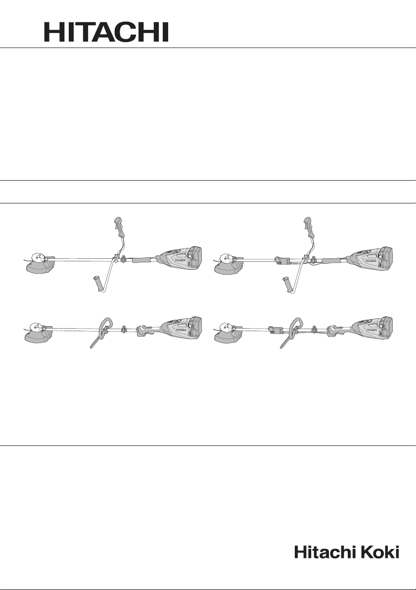
Cordless Grass Trimmer
Akku-Rasentrimmer
Coupe bordure à batterie
Tagliabordi a batteria
Snoerloze graskantenmaaier
Cortaseto a batería
Corta - relva a batería
CG 36DL • CG 36DL(L) • CG 36DAL • CG 36DAL(L)
CG36DL
CG36DL(L)
Read through carefully and understand these instructions before use.
Diese Anleitung vor Benutzung des Werkzeugs sorgfältig durchlesen und verstehen.
Lire soigneusement et bien assimiler ces instructions avant usage.
Prima dell’uso leggere attentamente e comprendere queste instruzioni.
Deze gebruiksaanwijzing s.v.p. voor gebruik zorgvuldig doorlezen.
Leer cuidadosamente y comprender estas instrucciones antes del uso.
Antes de usar, leia com cuidado para assimilar estas instruções.
CG36DAL
CG36DAL(L)
Handling instructions
Bedienungsanleitung
Mode d’emploi
Istruzioni per l’uso
Gebruiksaanwijzing
Instrucciones de manejo
Instruções de uso
Page 2
1234
1
5
4
3
8
1
0
7
2
6
9
1
2
5678
!
@
NOMAL
HIGH
%
*
$
w
#
&
9101112
s
d
a
a
^
q
g
f
î
#
e
Å
∏
)
(
#
u
p
r
∏
y
t
i
o
Î
Ø
h
13 14 15 16
˝
BL36200
Ï
#
î
Å
∏
Ø
Î
∏
7
Í
7
Í
#
Â
7
◊ı
17 18 19 20
j
k
l
2
Ó
Ô
Ò
Ú
¸
˛
Ç
p
p
;
Ô
Ó
;
Ú
Ò
˜
Â
Page 3
21 22 23 24
a
v
1.68 mm
2.38 mm
c
z
x
b
n
/
c
;
c
,
m
/
¡
.
25 26 27 28
™
¢
¶
•
∞
§
£
150 m m
§
29 30 31
º
b
⁄
§
10-15 cm
¤
32 33 34 35
fi
‡
fl
‡
!
NOMAL
HIGH
!
NOMAL
HIGH
‚
¶
¶
‹
·
ª
›
·
‚
36 37 38 39
NOMAL
HIGH
·
Œ
‚
·
‚
3
Page 4
40 41 42
#
´
Ô
b
„
43 44 45
‰
ˇ
Á
4 mm
10 mm
Ü
ˇ
4
Page 5

English Deutsch Français Italiano
Rechargeable battery Akkumulator Batterie rechargeable Batteria ricaricabile
1
Latch Schnapper Loquet Fermo
2
Battery cover Akkumulatorabdeckung Couvercle de la batterie Coperchio della batteria
3
Terminals Anschlüsse Bornes Terminali
4
Ventilation holes Belüftungslöcher Orifi ces de ventilation Fori di ventilazione
5
Push Drücken Pousser Spingere
6
Insert Einsatz Insérer Inserire
7
Pull out Herausziehen Tirer Estrarre
8
Pilot lamp Kontrollampe Lampe témoin Spia
9
Line Leitung Ligne Linea
0
Power button Einschalttaste Bouton d'alimentation Pulsante di alimentazione
!
Remaining battery
@
indicator lamp
Main pipe Hauptrohr Tuyau principal Tubo principale
#
Housing side Gehäuseseite Côté bâti Lato alloggiamento
$
Loop handle Bügelgriff Poignée Impugnatura ad anello
%
Handle fi xture Griff einbau Fixation pour poignée
^
M6×43 bolts M6×43-Schrauben 43 boulons M6 Bulloni M6×43
&
M6 nuts M6-Muttern Ecrous M6 Dadi M6
*
Handle right Griff rechts Poignée droite Impugnatura destra
(
Lever Hebel Levier Leva
)
Handle left Griff links Poignée gauche Impugnatura sinistra
q
Handle fi xture Griff einbau Fixation de la poignée
w
M5 × 25 hex. Socket bolts
e
Locking lever Verriegelungshebel Levier de blocage Leva di bloccaggio
r
Release Lösen Relâcher Rilascio
t
Extend Verlängern Étendre Estensione
y
Holder case Halterungsgehäuse Support du boîtier Scatola di alloggiamento
u
Lock Sperren Verrou Blocco
i
Projection of locking lever
o
Hole Loch Orifi ce Foro
p
Cover Abdeckung Capot Coperchio
a
Knife Messer Lame Coltello
s
D5 tapping screw D5-Blechschraube Vis autotaraudeuse D5 Vite autofi lettante D5
d
Cover bracket Schutzhalter Support du capot Staff a del coperchio
f
M6×25 hex. socket button
g
bolts
Cover holder Abdeckungshalterung
h
Flange ass’y Flanschbaueinheit Bride d’assemblage Gruppo fl angia
j
Wing Flügel Ailette Ala
k
Motor case Motorgehäuse Carter de moteur Scatola del motore
l
Hex. bar wrench 4 mm
;
LadezustandKontrollleuchte
M5 x 25
Innensechskantschrauben
Vorsprung des
Verriegelungshebels
M6×25-InnensechskantRundkopfschrauben
4-mm-SechskantInbusschlüssel
Témoin lumineux de
puissance batterie résiduelle
25 x boulons à tête
hexagonale M5
Projection du levier de
verrouillage
Boulons à tête creuse
hexagonale M6×25
Dispositif de retenue du
capot
Clé à barre hex. de 4mm
Spia luminosa batteria
restante
Dispositivo di fi ssaggio
dell’impugnatura
Dispositivo di fi ssaggio
dell’impugnatura
Bulloni con testa esagonale
incassata M5 x 25
Sporgenza della leva di
bloccaggio
Bulloni con testa esagonale
incassata M6
Supporto del coperchio
Chiave a barra esagonale
da 4 mm
×
25
5
Page 6

English Deutsch Français Italiano
Threaded fastener of the
z
motor case
Hole Loch Trou
x
Nylon head Nylonkopf Tête du fi l de nylon Testa di nylon
c
Screw (left rotation) Schraube (Linksgewinde)
v
Nylon line Nylonfaden Fil nylon Filo di nylon
b
Tap Kl op fe n Tap ote r F il et ta tor e
n
Button Knopf Bouton Pulsante
m
Tap/release Tippen/Verlängern Appuyez/Relâchez Tocco/rilascio
,
Wear limit mark (2 marks)
.
Extends in 30 mm
/
increments
Appropriate length 90 –
¡
110 mm
Cover Abdeckung Capot Coperchio
™
Case Gehäuse
£
Hook Haken Crochet Gancio
¢
Press tabs (2 areas)
∞
Reel Rolle Bobine Bobina
§
Groove Nut Rainure Scanalatura
¶
Fold back the middle part
•
Direction to wind nylon
ª
cord
Secure in the stopper Im Stopper sichern Fixez dans l'arrêt Fissare nel tappo
º
Stopper Stopper L'arrêt Tappo
⁄
Eyelet line guide Fadenführungsöse L'œillet du guide-fi l. Linea guida occhiello
¤
While holding the reel
‹
String the line through the
›
eyelet line guide
Locking holes of cover
fi
(2 holes)
Tabs of case (2 tabs)
fl
Power lamp Betriebsleuchte Témoin d’alimentation Spia di alimentazione
‡
Handle Griff Poignée Impugnatura
°
Lock lever Verriegelungshebel Levier de verrouillage Leva di bloccaggio
·
Lever Hebel Levier Leva
‚
Speed dial
Œ
Projection of locking lever
„
Wear limit Verschleißgrenze Limite d’usure Limite di usura
´
Brush cap Motorsensenaufsatz Bouchon de porte-balai Coperchio della spazzola
‰
Nail of carbon brush Klaue der Kohlebürste Clou de balai en carbone
ˇ
Protrusion of carbon
Á
brush
6
Schraubgewinde im
Motorgehäuse
Verschleißgrenzenmarke
(2 Marken)
Verlängerung à 30 mm
Ungefähre Länge 90 – 110 mmLongueur appropriée 90
Drucklaschen
(2 Bereiche)
Den mittleren Teil
zurückklappen
Wickelrichtung des
Nylonfadens
Während die Rolle
gehalten wird
Faden durch die
Fadenführungsöse führen
Rastlöcher in der
Abdeckung (2 Löcher)
Laschen am Gehäuse
(2 Laschen)
Geschwindigkeitswählschalter
Verriegelungshebelvo rspr ung
Krempe der Kohlebürste Saillie de balai en carbone
Élément de fi xation fi leté
du carter moteur
Vis (rotation vers la
gauche)
Marque de limite d'usure
(2 marques)
Extensions par segments
de 30 mm
à 110 mm
Châssis
Appuyez sur les
languettes (2 zones)
Replier la partie centrale Ripiegare la parte centrale
Direction pour enrouler du
cordon en nylon
Tenant la bobine Mentre si tiene la bobina
Enfi lez le fi l à travers
l'œillet du guide-fi l.
Trous de verrouillage du
couvercle (2 trous)
Languettes du châssis
(2 languettes)
Cadran des vitesses Regolatore di velocità
Projection du levier de
verrouillage
Dispositivo di fi ssaggio
fi lettato della scatola
motore
Foro
Vite (rotazione a sinistra)
Contrassegno limite di
usura (2)
Si estende in incrementi
di 30 mm
Lunghezza appropriata
90 – 110 mm
Tes ti na
Pressione linguette
(2 aree)
Direzione di avvolgimento
cavo di nylon
Inserire il fi lo attraverso la
linea guida dell’occhiello
Fori di bloccaggio del
coperchio (2)
Linguette testina (2)
Sporgenza della leva di
bloccaggio
Chiodo di spazzola di
carbone
Sporgenza di spazzola di
carbone
Page 7

English Deutsch Français Italiano
Contact portion of brush
Ü
tube
Pull Ziehen Tirer Tirare
î
Hanger Hänger Suspension Dispositivo di aggancio
Ø
Bracket Bügel Support Staff a
∏
Quick-release belt Schnelllöseriemen
Å
Hook Haken Crochet Gancio
Í
Quick-release bracket Schnelllösebügel
Î
Press Drücken Appuyer Premere
Ï
Release mechanism Lösemechanismus
˝
Box spanner Steckschlüssel Clé à douilles Chiave a tubo
Ó
Tighten Festziehen Serrer Serrare
Ô
Loosen Lockern Desserrer Allentare
Nut cover Mutterabdeckung Cache écrou Copridado
Ò
Cutting blade Schneideklinge Lame de coupe Lama di taglio
Ú
Flange assy Flanschbaueinheit Bride Assieme fl angia
¸
Motor case Motorgehäuse Carter de moteur Scatola del motore
˛
Cutting blade cover Klingenschutz
Ç
to detach Abnehmen détacher per staccare
◊
to attach Anbringen attacher per fi ssare
ı
Left side M10 installation
Ñ
nut
Projection of fl ange assy
Â
Kontaktfl äche des
Bürstenrohrs
Linke M10Installationsmutter
Vorsprung der
Flanschbaueinheit
Partie de contact du tube
de balai
Courroie à déverrouillage
rapide
Support à déverrouillage
rapide
Mécanisme de
déverrouillage
Capot de la lame de
coupe
Écrou d’installation M10
côté gauche
Projection de la bride
Parte di contatto del tubo
della spazzola
Cinghia a rilascio rapido
Staff a a rilascio rapido
Meccanismo di rilascio
Coprilama
Dado di installazione M10
lato sinistro
Sporgenza dell’assieme
fl angia
7
Page 8

Nederlands Español Português
Oplaadbare batterij Batería recargable Bateria de recarregável
1
Vergrendeling Enganche Lingüeta
2
Batterijdeksel Cubierta de batería Tampa da bateria
3
Aansluitpunten Terminales Terminais
4
Vent ilat ieopeningen Orifi cios de ventilación Orifícios de ventilação
5
Indrukken Empujar Empurrar
6
Insteken Insertar Inserir
7
Uittrekken Sacar Retirar
8
Controlelampje Lámpara piloto Lâmpada piloto
9
Lijn Línea Linha
0
Aan/uit-knop Botón de alimentación Botão de alimentação
!
Indicatielampje
@
resterende acculading
Hoofdpijp Tubo principal Tubo principal
#
Zijkant behuizing Lado de la carcasa Lado da carcaça
$
Lushandvat Empuñadura de bucle Pega de olhal
%
Bevestiging van handvat Soporte de mango Fixador do punho
^
M6×43 bouten Pernos M6x43 Parafusos M6×43
&
M6 moeren tuercas M6 Porcas M6
*
Handvatstang rechts Asidero derecho Pega direita
(
Hendel Palanca Alavanca
)
Handvatstang links Asidero izquierdo Pega esquerda
q
Verbindingsbeugel voor
w
handvatstangen
M5 x 25 zeskantige
e
inbusbouten
Blokkeerhendel Palanca de fi jación Alavanca de bloqueio
r
Ontgrendelen Soltar Libertação
t
Uittrekken Extender Abrir
y
Houderbehuizing Carcasa de soporte Caixa do suporte
u
Vergrendelen Bloquear Bloqueio
i
Uitsteeksel van
o
blokkeerhendel
Gat Orifi cio Orifício
p
Deksel Cubierta Tampa
a
Mes Cuchillo Lâmina
s
D5 tapschroef Tornillo de rosca D5 Parafuso roscante D5
d
Dekselsteun Abrazadera de cubierta Suporte da tampa
f
M6×25 bolkop
g
inbusbouten
Dekselhouder Soporte de cubierta Suporte da tampa
h
Toebehoren van fl ens Conjunto de brida Prato
j
Vleugel Pestaña Asa
k
Motorbehuizing Carcasa de motor Caixa do motor
l
Inbussleutel 4 mm
;
Bevestiging met
schroefdraad voor
z
motorhuis
8
Indicador luminoso de
batería restante
Accesorio del asidero Fixador da pega
25 pernos Allen M5
Proyección de la palanca
de fi jación
Pernos inferiores de
cabeza hexagonal M6x25
Llave de barra hexagonal
de 4 mm
Cierre roscado de la
carcasa del motor
Luz de indicação da
autonomia da pilha
Parafusos sextavados
interiores M5 x 25
Projecção da alavanca de
bloqueio
Parafusos M6×25
de cabeça cilíndrica
sextavados
Chave hexagonal 4 mm
Rosca de aperto da caixa
do motor
Page 9

Nederlands Español Português
Gaatje Agujero Orifício
x
Nylon kop Cabezal de nailon Cabeça de nylon
c
Schroef (linksdraaiend) Tornillo (giro a izquierdas)
v
Nylondraad Cuerda de nylon Linha de nylon
b
Kloppen Llave Bater
n
Knop Botón Botão
m
Tap/ontgrendeling
,
Limietmarkering slijtage (2
.
markeringen)
Verlengt in stappen van
/
30 mm
Geschikte lengte 90 – 110 mmLongitud apropiada 90 –
¡
Deksel Cubierta Tampa
™
Behuizing Carcasa Caixa
£
Haak Gancho Gancho
¢
Tabs indrukken
∞
(2 gebieden)
Spoel Rollo Bobina
§
Groef Muesca Ranhura
¶
Klap het middelste
•
gedeelte terug
Richting voor oprollen
ª
nylondraad
Steek de stop er goed in Asegurar en el tapón Fixar no tampão
º
Stop Tapón Tampão
⁄
Draadgeleidingsoog Guía de la línea del orifi cio Ilhó guia de fi o
¤
Terwijl u de spoel
‹
vasthoudt
Steek de lijn door het
›
draadgeleidingsoog
Afsluitgaten van kap
fi
(2 gaten)
Tabs van behuizing
fl
(2 tabs)
Aan/uit lampje Lámpara de encendido Luz de alimentação
‡
Handvat Empuñadura Pega
°
Vergrendelhendel Palanca de bloqueo Alavanca de bloqueio
·
Hendel Palanca Alavanca
‚
Snelheidsregelaar Selector de velocidad Selector de velocidade
Œ
Uitsteeksel van
„
blokkeerhendel
Slijtagegrens Límite de uso Limite de desgaste
´
Borstelkap Tapa del cepillo Tampa da roçadora
‰
Nagel van koolborstel
ˇ
Uitsteeksel van
Á
koolborstel
Sacar/Liberar Bater/libertar
Marca de límite de
desgaste (2 marcas)
Se extiende en
incrementos de 30 mm
110 mm
Presionar las pestañas
(2 áreas)
Plegar la parte central Rebater a parte central
Dirección para el
bobinado el cable de
nailon
Mientras se sujeta el rollo
Haga pasar la línea a
través de la guía de línea
del orifi cio
Agujeros de bloqueo de la
cubierta (2 agujeros)
Pestañas de la carcasa
(2 pestañas)
Proyección de la palanca
de fi jación
Uña de escobilla de
carbón
Saliente de escobilla de
carbón
Parafuso (rotação para a
esquerda)
Marca de limite de
desgaste (2 marcas)
Estende em incrementos
de 30 mm
Comprimento apropriado
90 – 110 mm
Abas de pressão (2 áreas)
Direcção para enrolar o fi o
de nylon
Enquanto segura na
bobina
Passe o fi o pelo ilhó guia
de fi o
Orifícios de fi xação da
tampa (2 orifícios)
Abas da caixa (2 abas)
Projecção da alavanca de
bloqueio
Prego da escova de
carvão
Saliência da escova de
carvão
9
Page 10

Nederlands Español Português
Contactgedeelte van
Ü
borstelbuis
Tre kk en T ir ar Pu xar
î
Hanger Colgador Suporte
Ø
Beugel Abrazadera Apoio
∏
Snelontgrendelingsriem
Å
Haak Gancho Gancho
Í
Snelontgrendelingsbeugel
Î
Drukken Presionar Premir
Ï
Ontgrendelingsmechanisme
˝
Pijpsleutel Llave tubular Chave de caixa
Ó
Vastdr aaien Apret ar A pert ar
Ô
Losdraaien Afl ojar Desapertar
Moerafdekking Cubierta de la tuerca Tampa da porca
Ò
Snijmes Cuchilla de corte Lâmina de corte
Ú
Flens Ensamble de la brida Conjunto da fl ange
¸
Motorbehuizing Carcasa del motor Caixa do motor
˛
Afdekking van snijmes
Ç
losmaken para desinstalar para desengatar
◊
bevestigen para instalar para engatar
ı
Linker M10
Ñ
bevestigingsmoer
Uitsteeksel van fl ens
Â
Parte de contacto del tubo
de escobilla
Correa de desenganche
rápido
Abrazadera de
desenganche rápido
Mecanismo de
desenganche
Funda de la cuchilla de
corte
Tuerca de instalación M10
de lateral izquierdo
Proyección de ensamble
de la brida
Secção de contacto do
tubo da escova
Alça de libertação rápida
Suporte de libertação
rápida
Mecanismo de libertação
Tampa da lâmina de corte
Porca de instalação M10
lado esquerdo
Projecção do conjunto da
fl ange
10
Page 11
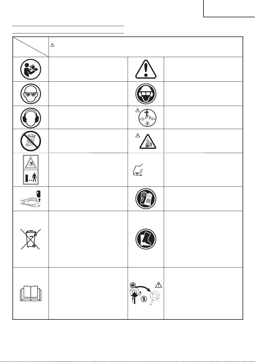
MEANINGS OF SYMBOLS
Symbols
WARNING
The following show symbols used for the machine. Be sure that you understand their meaning before
use.
Read all safety warnings and all
instructions.
Failure to follow the warnings and
instructions may result in electric shock,
fi re and/or serious injury.
(Original instructions)
English
Read, understand and follow all
warnings and instructions in this manual
and on the unit.
Always wear eye protection.
Always wear hearing protection.
Always wear eye, head and ear
protectors when using this unit.
Keep all children, bystanders and
helpers 15 m away from the unit. If
anyone approaches you, stop the unit
and cutting attachment immediately.
Do not expose to moisture. Be careful of thrown objects.
Shows maximum shaft speed. Do not
Max
Keep bystanders away.
Remove battery before adjusting or
cleaning and before leaving the machine
unattended for any period.
Only for EU countries
Do not dispose of electric tools together
with household waste material!
In observance of European Directive
2002/96/EC on waste electrical
and electronic equipment and its
implementation in accordance with
national law, electric tools that have
reached the end of their life must be
collected separately and returned to an
environmentally compatible recycling
facility.
It is important that you read, fully
understand and observe the following
safety precautions and warnings.
Careless or improper use of the unit may
cause serious or fatal injury.
8,000 min
use the cutting attachment whose max
-1
rpm is below the shaft rpm.
Gloves should be worn when necessary,
e.g., when assembling cutting
equipment.
Use anti-slip and sturdy footwear.
Blade thrust may occur when the
spinning blade contacts a solid object in
the critical area. A dangerous reaction
may occur causing the entire unit and
operator to be thrust violently. This
reaction is called blade thrust. As a
result, the operator may lose control
of the unit which may cause serious or
fatal injury. Blade thrust is more likely to
occur in areas where it is diffi cult to see
the material to be cut.
11
Page 12

English
WHAT IS WHAT?
1. Lever: Trigger for activating the unit.
2. Lock lever: Lever that prevents the accidental operation
of the trigger.
3. Motor: Battery-driven, disk-shaped motor.
4. Cover: Protects operator from fl ying debris.
5. Battery: Power source to drive the unit.
6. Power button: Button for switching the units power unit's
power ON or OFF.
7. Speed dial: Dial for adjusting the speed of the motor.
8. Handle right: Handle with lever located on the right side
of the unit.
9. Handle left: Handle located on the left side of the unit.
10. Handle fi xture: Secures the handle to the unit.
11. Hang: Used for attaching a shoulder or hanger belt to the
unit.
12. Shoulder belt: Harness with release mechanism for
combined use with battery.
13. Hanger belt: Harness with release mechanism for
combined use with back pack power supply.
14. Blade (Optional accessories): Metal blade cutting tool.
15. Nut cover (Optional accessories): Holds down the blade.
16. Left side M10 installation nut (Optional accessories):
Secures the blade to the unit.
17. Charger: For charging the battery.
1
3
4
9
2
8
6
11
10
CG36DL
1212
13
5
7
14
15
12
16
17
Page 13

English
GENERAL POWER TOOL SAFETY WARNINGS
WARNING
Read all safety warnings and all instructions.
Failure to follow the warnings and instructions may result in
electric shock, fi re and/or serious injury.
Save all warnings and instructions for future reference.
The term “power tool” in the warnings refers to your mainsoperated (corded) power tool or battery-operated (cordless)
power tool.
1) Work area safety
a) Keep work area clean and well lit.
Cluttered or dark areas invite accidents.
b) Do not operate power tools in explosive
atmospheres, such as in the presence of
fl ammable liquids, gases or dust.
Power tools create sparks which may ignite the dust
or fumes.
c) Keep children and bystanders away while
operating a power tool.
Distractions can cause you to lose control.
2) Electrical safety
a) Power tool plugs must match the outlet.
Never modify the plug in any way.
Do not use any adapter plugs with earthed
(grounded) power tools.
Unmodifi ed plugs and matching outlets will reduce
risk of electric shock.
b) Avoid body contact with earthed or grounded
surfaces, such as pipes, radiators, ranges and
refrigerators.
There is an increased risk of electric shock if your
body is earthed or grounded.
c) Do not expose power tools to rain or wet
conditions.
Water entering a power tool will increase the risk of
electric shock.
d) Do not abuse the cord. Never use the cord for
carrying, pulling or unplugging the power tool.
Keep cord away from heat, oil, sharp edges or
moving parts.
Damaged or entangled cords increase the risk of
electric shock.
e) When operating a power tool outdoors, use an
extension cord suitable for outdoor use.
Use of a cord suitable for outdoor use reduces the
risk of electric shock.
f) If operating a power tool in a damp location
is unavoidable, use a residual current device
(RCD) protected supply.
Use of an RCD reduces the risk of electric shock.
3) Personal safety
a) Stay alert, watch what you are doing and use
common sense when operating a power tool.
Do not use a power tool while you are tired
or under the infl uence of drugs, alcohol or
medication.
A moment of inattention while operating power tools
may result in serious personal injury.
b) Use personal protective equipment. Always
wear eye protection.
Protective equipment such as dust mask, non-skid
safety shoes, hard hat, or hearing protection used for
appropriate conditions will reduce personal injuries.
c) Prevent unintentional starting. Ensure the
switch is in the off position before connecting to
power source and/or battery pack, picking up or
carrying the tool.
Carrying power tools with your fi nger on the switch or
energising power tools that have the switch on invites
accidents.
d) Remove any adjusting key or wrench before
turning the power tool on.
A wrench or a key left attached to a rotating part of the
power tool may result in personal injury.
e) Do not overreach. Keep proper footing and
balance at all times.
This enables better control of the power tool in
unexpected situations.
f) Dress properly. Do not wear loose clothing or
jewellery. Keep your hair, clothing and gloves
away from moving parts.
Loose clothes, jewellery or long hair can be caught in
moving parts.
g) If devices are provided for the connection of
dust extraction and collection facilities, ensure
these are connected and properly used.
Use of dust collection can reduce dust related
hazards.
4) Power tool use and care
a) Do not force the power tool. Use the correct
power tool for your application.
The correct power tool will do the job better and safer
at the rate for which it was designed.
b) Do not use the power tool if the switch does not
turn it on and off .
Any power tool that cannot be controlled with the
switch is dangerous and must be repaired.
c) Disconnect the plug from the power source and/
or the battery pack from the power tool before
making any adjustments, changing accessories,
or storing power tools.
Such preventive safety measures reduce the risk of
starting the power tool accidentally.
d) Store idle power tools out of the reach of children
and do not allow persons unfamiliar with the
power tool or these instructions to operate the
power tool.
Power tools are dangerous in the hands of untrained
users.
e) Maintain power tools. Check for misalignment or
binding of moving parts, breakage of parts and
any other condition that may aff ect the power
toolsʼ operation.
If damaged, have the power tool repaired before
use.
Many accidents are caused by poorly maintained
power tools.
f) Keep cutting tools sharp and clean.
Properly maintained cutting tools with sharp cutting
edges are less likely to bind and are easier to control.
g) Use the power tool, accessories and tool bits
etc. in accordance with these instructions,
taking into account the working conditions and
the work to be performed.
Use of the power tool for operations diff erent from
those intended could result in a hazardous situation.
5) Battery tool use and care
a) Recharge only with the charger specifi ed by the
manufacturer.
A charger that is suitable for one type of battery pack
may create a risk of fi re when used with another
battery pack.
b) Use power tools only with specifi cally designated
battery packs.
Use of any other battery packs may create a risk of
injury and fi re.
13
Page 14

English
c) When battery pack is not in use, keep it away
from other metal objects like paper clips, coins,
keys, nails, screws, or other small metal objects
that can make a connection from one terminal to
another.
Shorting the battery terminals together may cause
burns or a fi re.
d) Under abusive conditions, liquid may be ejected
from the battery; avoid contact. If contact
accidentally occurs, fl ush with water. If liquid
contacts eyes, additionally seek medical help.
Liquid ejected from the battery may cause irritation or
burns.
6) Service
a) Have your power tool serviced by a qualifi ed
repair person using only identical replacement
parts.
This will ensure that the safety of the power tool is
maintained.
PRECAUTION
Keep children and infi rm persons away.
When not in use, tools should be stored out of reach of
children and infi rm persons.
GRASS TRIMMER SAFETY WARNINGS
IMPORTANT
READ CAREFULLY BEFORE USE
KEEP FOR FUTURE REFERENCE
Safe operation practices
● Training
a) Read the instructions carefully. Be familiar with the
controls and the proper use of the machine.
b) Never allow people unfamiliar with these instructions
or children to use the machine. Local regulations can
restrict the age of the operator.
c) Keep in mind that the operator or user is responsible for
accidents or hazards occurring to other people or their
property.
● Preparation
a) Never operate the machine while people, especially
children, or pets are nearby.
b) Wear eye protection, gloves and stout shoes at all times
while operating the machine.
● Operation
a) Use the machine only in daylight or good artifi cial light.
b) Never operate the machine with damaged cover or
without cover in place.
c) Switch on the motor only when the hands and feet are
away from the cutting means.
d) Always disconnect the machine from the power supply
(i.e. remove the plug from the mains or remove the
disabling device)
– whenever leaving the machine unattended;
– before clearing a blockage;
– before checking, cleaning or working on the machine;
– after striking a foreign object;
– whenever the machine starts vibrating abnormally.
e) Take care against injury to feet and hands from the
cutting means.
f) Always ensure that the ventilation openings are kept
clear of debris.
g) Never modify the unit/machine in any way. Do not use
your unit/machine for any job except that for which it is
intended.
14
● Maintenance, transport and storage
a) Disconnect the machine from the power supply (i.e.
remove the plug from the mains or remove the disabling
device) before carrying out maintenance or cleaning
work.
b) Use only the manufacturer’s recommended
replacement parts and accessories.
c) Inspect and maintain the machine regularly. Have the
machine repaired only by an authorized repairer.
d) When not in use, store the machine out of the reach of
children.
e) When transporting in a vehicle or storage, cover blade
with blade cover.
PRECAUTIONS FOR CORDLESS GRASS
TRIMMER
WARNING
1. Exercise patience in all work with the tool. And dress
properly to keep warm.
2. Plan all work ahead to prevent accidents.
3. Do not operate the tool at night or under bad weather
conditions when visibility is poor. And do not operate the
tool when it is raining or right after it has been raining.
Working on slippery ground could lead to an accident if
you lose your balance.
4. Inspect the nylon head before starting work.
Do not use the tool if the nylon head is cracked, scarred
or bent.
Make sure the nylon head is properly attached. A nylon
head that falls apart or comes loose during operation
could cause an accident.
5. Be sure to attach the cover before starting work.
Operating the tool without this parts could lead to injury.
6. Be sure to attach the loop handle before starting work.
Make sure it is not loose but properly attached before
starting work. Hold the loop handle fi rmly during work and
do not swing the tool around, but use the correct posture
and maintain your balance.
Losing your balance during work could lead to an injury.
7. Take care when starting the motor.
Place the tool on level ground.
Do not operate the tool within 15 m of people or animals.
Make sure that the nylon head does not come into
contact with the ground or trees and plants.
A careless start could lead to injury.
8. Do not secure the lock lever.
Accidentally pulling back the lever could lead to
unexpected injury.
9. Before leaving the tool, press the power button to turn it
off .
10. Operate the tool with care near electric cables, gas pipes
and similar installations.
11. Look out for and remove empty cans, wire, stones or
other obstacles before starting work. And do not work
near tree roots or rocks.
Working in such areas could damage the nylon head or
lead to injury.
12. Never touch the nylon head during operation.
Also make sure it does not come into contact with your
hair, clothes, etc.
13. In the following situations, turn off the motor and check
that the nylon head has stopped rotating.
To move to another work area.
To remove rubbish or grass that has become stuck in the
tool.
To remove from the work area obstacles or the rubbish,
grass and chips generated by trimming.
To lay down the tool.
Doing this with the nylon head still rotating could lead to
unexpected accidents.
Page 15

English
14. Do not use the tool within 15 m of another person.
When you work with someone else, maintain a distance
of more than 15 m.
Flying chips could lead to unexpected accidents.
When working on unstable surfaces like slopes, make
sure that your co-worker is not exposed to any hazards.
Use whistles or other means for calling the attention of
your co-workers.
15. When grass and other objects become entangled in the
nylon head, turn off the motor and make sure the nylon
head has stopped rotating before removing them.
Removing objects from the nylon head when it is still
rotating will lead to injury.
Continuing operation when foreign matter is stuck in the
nylon head may lead to damage.
16. If the tool is operating poorly and produces strange noise
or vibrations, turn off the motor immediately and ask your
dealer to have it inspected and repaired.
Continued use under these conditions could lead to
injury or tool damage.
17. If you drop or bump the tool, inspect it carefully to check
there is no damage, cracks or deformation.
Using a tool that is damaged, cracked or deformed could
result in injury.
18. Secure the tool during vehicle transport to ensure that it
lies still.
Failure to heed this warning may result in an accident.
19. This product contains a strong permanent magnet in the
motor.
Observe the following precautions regarding adhering of
chips to the tool and the eff ect of the permanent magnet
on electronic devices.
CAUTION
◯ Do not place the tool on a workbench or work area where
metal chips are present.
The chips may adhere to the tool, resulting in injury or
malfunction.
◯ If chips have adhered to the tool, do not touch it. Remove
the chips with a brush.
Failure to do so may result in injury.
◯ If you use a pacemaker or other electronic medical
device, do not operate or approach the tool.
Operation of the electronic device may be aff ected.
◯ Do not use the tool in the vicinity of precision devices
such as cell phones, magnetic cards or electronic
memory media.
Doing so may lead to misoperation, malfunction or loss of
data.
CAUTION
1. Do not turn on the nylon head for cutting objects other
than grass. Do not operate the tool in water puddles and
make sure that soil does not come into contact with the
nylon head.
2. The tool contains precision parts and should not be
dropped, exposed to strong impact or water.
The tool could be damaged or malfunction.
3. When the tool is to be stored after use or be transported,
remove the nylon head.
4. Do not expose the tool to insecticide and other chemicals.
Such chemicals could cause cracking and other damage.
5. Replace warning labels with new labels when they
become diffi cult to recognize or illegible and when they
start to peel.
Ask your dealer to provide the warning labels.
6. Do not touch the motor immediately after use since it may
be very hot.
PRECAUTIONS FOR BATTERY AND CHARGER
1. Always charge the battery at a temperature of 0°C –
40°C. A temperature of less than 0°C will result in over
charging which is dangerous. The battery cannot be
charged at a temperature higher than 40°C.
The most suitable temperature for charging is that of
20°C – 25°C.
2. When one charging is completed, leave the charger for
about 15 minutes before the next charging of battery.
Do not charge more than two batteries consecutively.
3. Do not allow foreign matter to enter the hole for
connecting the rechargeable battery.
4. Do not insert object into the air ventilation slots of the
charger.
Inserting metal objects or infl ammables into the charger
air ventilation slots will result in electrical shock hazard or
damaged charger.
5. Using an exhausted battery will damage the charger.
6. Bring the battery to the shop from which it was purchased
as soon as the post-charging battery life becomes too
short for practical use. Do not dispose of the exhausted
battery.
7. Never disassemble the rechargeable battery and
charger.
8. Never short-circuit the rechargeable battery. Shortcircuiting the battery will cause a great electric current
and overheat. It results in burn or damage to the battery.
9. Do not dispose of the battery in fi re. If the battery is burnt,
it may explode.
CAUTION ON LITHIUM-ION BATTERY
To extend the lifetime, the lithium-ion battery equips with the
protection function to stop the output.
In the cases of 1 to 3 described below, when using this
product, even if you are pulling the switch, the motor may
stop. This is not the trouble but the result of protection
function.
1. When the battery power remaining runs out, the motor
stops.
In such case, charge it up immediately.
2. If the tool is overloaded, the motor may stop. In this
case, release the switch of tool and eliminate causes of
overloading. After that, you can use it again.
3. If the battery is overheated under overload work, the
battery power may stop.
In this case, stop using the battery and let the battery
cool. After that, you can use it again.
Furthermore, please heed the following warning and caution.
WARNING
In order to prevent any battery leakage, heat generation,
smoke emission, explosion and ignition beforehand, please
be sure to heed the following precautions.
1. Make sure that swarf and dust do not collect on the
battery.
◯ During work make sure that swarf and dust do not fall on
the battery.
◯ Make sure that any swarf and dust falling on the power
tool during work do not collect on the battery.
◯ Do not store an unused battery in a location exposed to
swarf and dust.
◯ Before storing a battery, remove any swarf and dust that
may adhere to it and do not store it together with metal
parts (screws, nails, etc.).
2. Do not pierce battery with a sharp object such as a
nail, strike with a hammer, step on, throw or subject the
battery to severe physical shock.
3. Do not use an apparently damaged or deformed battery.
15
Page 16
English
4. Do not use the battery in reverse polarity.
5. Do not connect directly to an electrical outlets or car
cigarette lighter sockets.
6. Do not use the battery for a purpose other than those
specifi ed.
7. If the battery charging fails to complete even when a
specifi ed recharging time has elapsed, immediately stop
further recharging.
8. Do not put or subject the battery to high temperatures or
high pressure such as into a microwave oven, dryer, or
high pressure container.
9. Keep away from fi re immediately when leakage or foul
odor are detected.
10. Do not use in a location where strong static electricity
generates.
11. If there is battery leakage, foul odor, heat generated,
discolored or deformed, or in any way appears abnormal
during use, recharging or storage, immediately remove it
from the equipment or battery charger, and stop use.
CAUTION
1. If liquid leaking from the battery gets into your eyes, do not
rub your eyes and wash them well with fresh clean water
such as tap water and contact a doctor immediately.
If left untreated, the liquid may cause eye-problems.
2. If liquid leaks onto your skin or clothes, wash well with
clean water such as tap water immediately.
There is a possibility that this can cause skin irritation.
3. If you fi nd rust, foul odor, overheating, discolor,
deformation, and/or other irregularities when using the
battery for the fi rst time, do not use and return it to your
supplier or vendor.
WARNING
If an electrically conductive foreign object enters the terminals
of the lithium ion battery, a short-circuit may occur resulting
in the risk of fi re. Please observe the following matters when
storing the battery.
◯ Do not place electrically conductive cuttings, nails,
steel wire, copper wire or other wire in the storage
case.
◯ Either install the battery in the power tool or store
by securely pressing into the battery cover until the
ventilation holes are concealed to prevent shortcircuits (See Fig. 1).
SPECIFICATIONS
POWER TOOL
Model CG36DL CG36DL(L) CG36DAL CG36DAL(L)
Pole type Straight type Extendable type
Cutting capacity diameter 310 mm
Rotation direction Counterclockwise as seen from above
No-load speed 5800 – 7000 min
BSL3620
Operating time on one charge*
(When supplied rechargeable battery is fully
charged)
Battery BSL3620: Li-ion 36 V (2.0 Ah 10 cells)
Weight (with nylon head, rechargeable
battery, shoulder belt and cover)
The data in the above table is provided only as an example. Since type of grass, ambient temperature, rechargeable
*
battery characteristics, work methods, etc. can vary widely the above should only be used as a rough guideline.
Conditions: Outer diameter of nylon head 310 mm, speed dial set to Normal or High. (lever left ON all the time)
35 min (Normal)
15 min (High)
BL36200
5.5 h (Normal)
2.5 h (High)
5.7 kg 5.5 kg 6.0 kg 5.8 kg
-1
CHARGER
Model UC36YRSL
Charging voltage 14.4 V – 36 V
Weight 0.7 kg
16
STANDARD ACCESSORIES
1 Battery (BSL3620) ................................ 1
2 Charger (UC36YRSL) .......................... 1
3 Nylon head ........................................... 1
4 Cover .................................................... 1
CG36DL
(LBR)
5 Hex. bar wrench 4 mm ......................... 1
6 17×19 Combi box wrench..................... 1
7 Protective glass .................................... 1
8 Shoulder belt ........................................ 1
9 Hanger belt ........................................... 1
0 Battery cover ........................................ 1
Page 17
English
1 Nylon head ............................................1
2 Cover ....................................................1
CG36DL
(NN)
CG36DL(L)
(LBR)
CG36DL(L)
(NN)
CG36DAL
CG36DAL(L)
(LBR)
CG36DAL
CG36DAL(L)
(NN)
Standard accessories are subject to change without notice.
3 Hex. bar wrench 4 mm ..........................1
4 17×19 Combi box wrench .....................1
5 Protective glass ....................................1
6 Shoulder belt ........................................1
7 Hanger belt ...........................................1
1 Battery (BSL3620) ................................1
2 Charger (UC36YRSL) ...........................1
3 Nylon head ............................................1
4 Cover ....................................................1
5 Hex. bar wrench 4 mm ..........................1
6 17×19 Combi box wrench .....................1
7 Protective glass ....................................1
8 Shoulder belt ........................................1
9 Hanger belt ...........................................1
0 Battery cover ........................................1
1 Nylon head ............................................1
2 Cover ....................................................1
3 Hex. bar wrench 4 mm ..........................1
4 17×19 Combi box wrench .....................1
5 Protective glass ....................................1
6 Shoulder belt ........................................1
7 Hanger belt ...........................................1
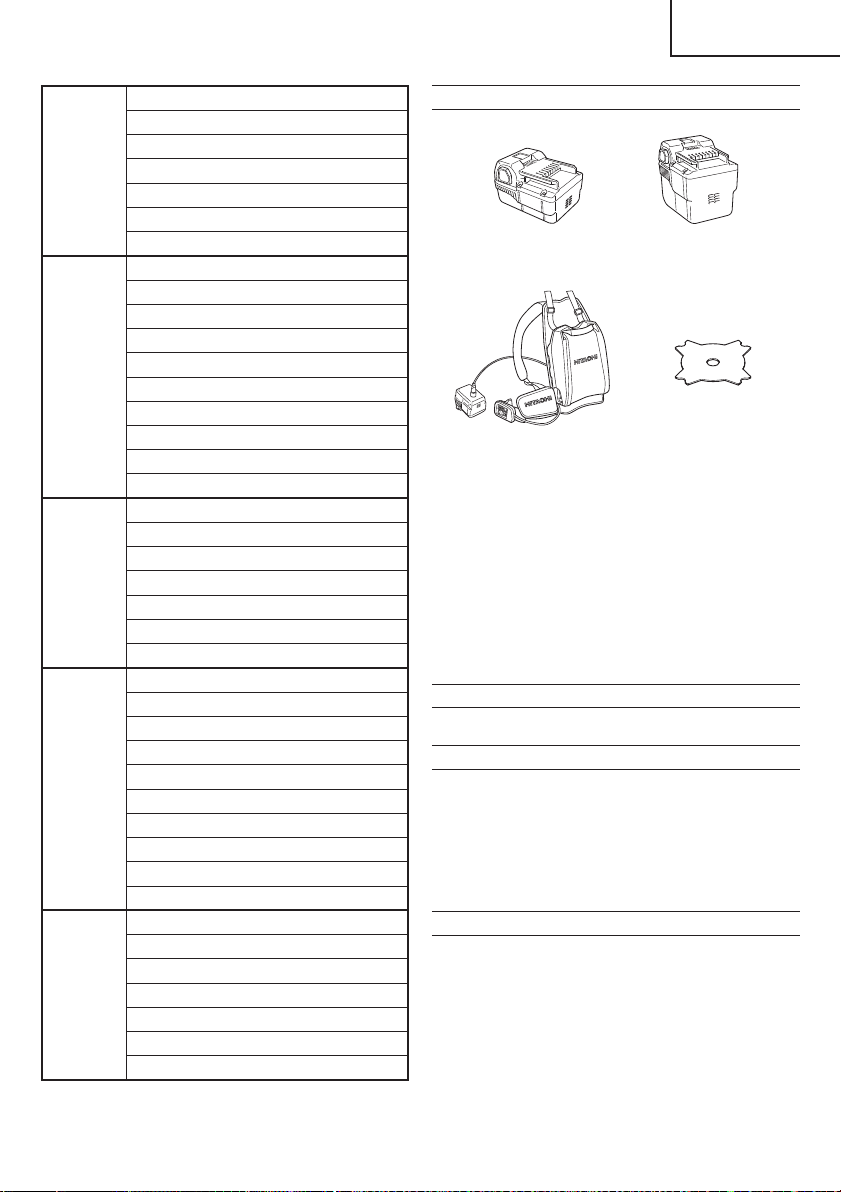
OPTIONAL ACCESSORIES (sold separately)
◯ Battery
(BSL3620) (BSL3626)
◯ Back pack power supply ○ Cutting blade
(CG36DL only)
(BL36200)
NOTE
For details of the operations, please see the BL36200
instruction manual.
When using the Cutting blade, have the Nut cover, Left
side M10 installation nut and Counter weight set ready for
installation.
◯ Nut cover (CG36DL only)
◯ Left side M10 installation nut (CG36DL only)
◯ Counter weight set (CG36DL only)
NOTE
For details of the operations, please see the Counter
weight set instruction manual.
Optional accessories are subject to change without notice.
APPLICATIONS
Trimming, scaling and mowing of weed.
BATTERY REMOVAL/INSTALLATION
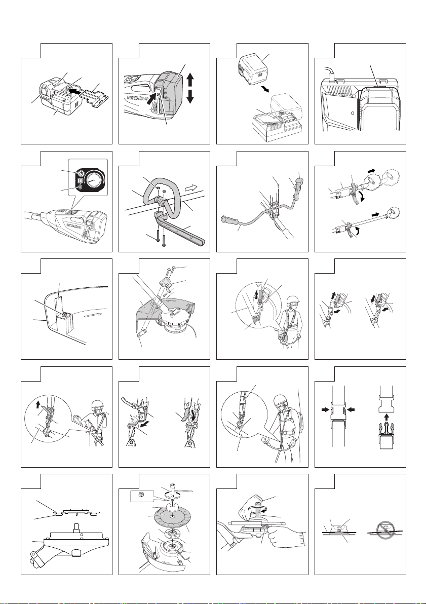
1. Battery removal
Hold the housing tightly and push the battery latches to
remove the battery (see Fig. 2).
CAUTION
Never short-circuit the battery.
2. Battery installation
Insert the battery while observing its polarities (see Fig.
2).
CHARGING
Before using the power tool, charge the battery as follows.
1. Connect the charger’s power cord to a receptacle.
When the power cord is connected, the charger’s pilot
lamp will blink in red. (At 1-second intervals)
2. Insert the battery into the charger.
Firmly insert the battery into the charger until the line is
visible, as shown in Fig. 3 and 4.
3. Charging
When inserting a battery in the charger, charging will
commence and the pilot lamp will light continuously in
red.
When the battery becomes fully recharged, the pilot lamp
will blink in red. (At 1-second intervals) (See Table 1)
17
Page 18
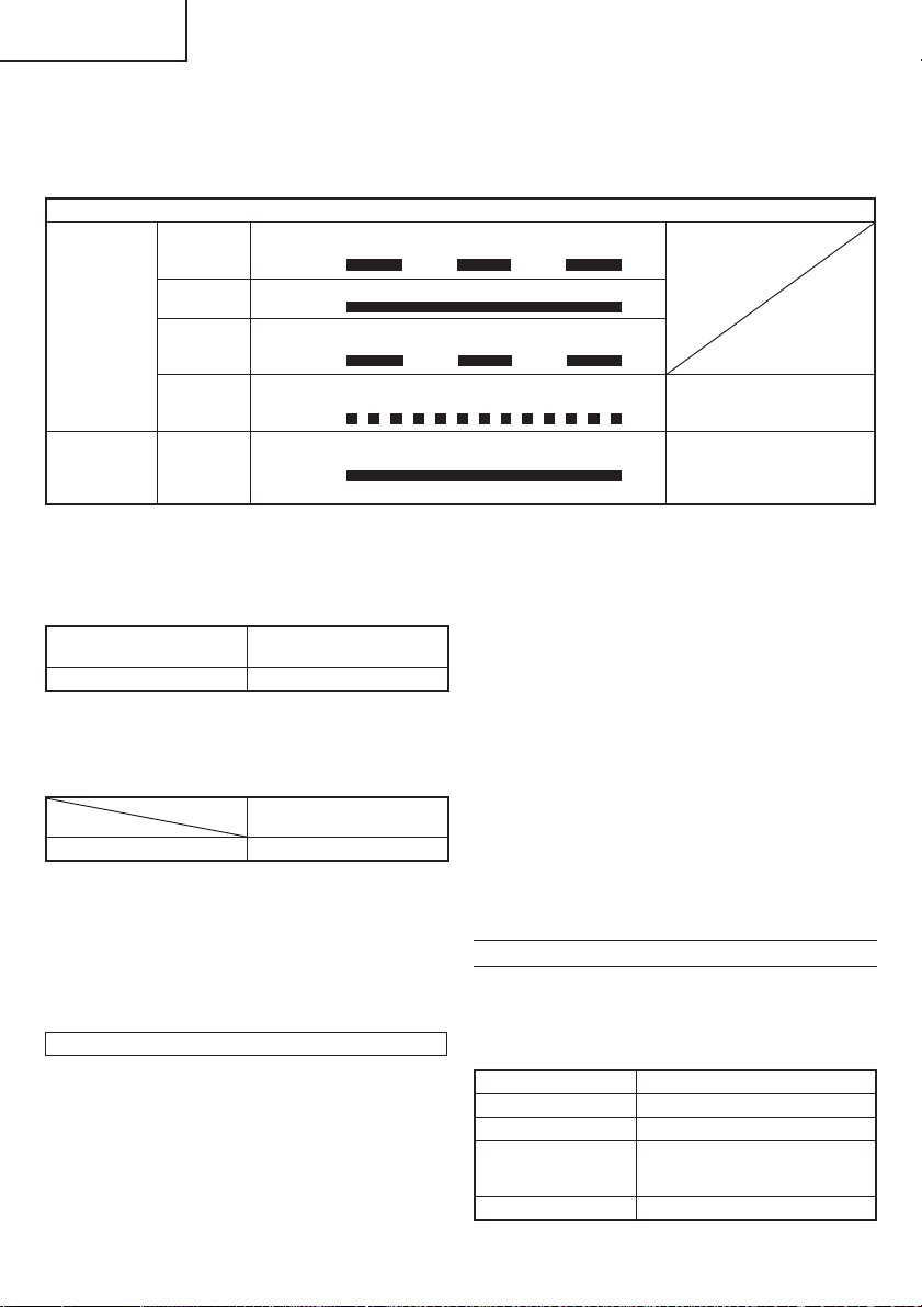
English
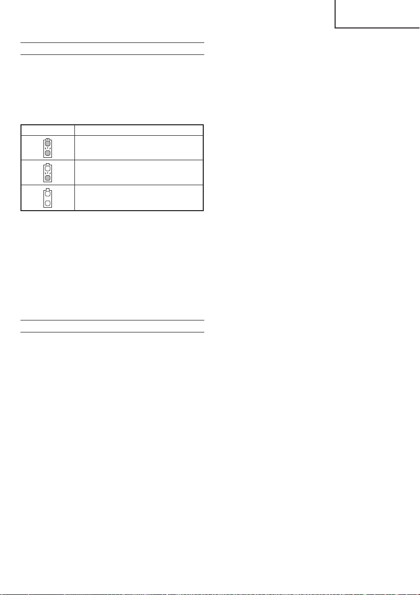
(1) Pilot lamp indication
The indications of the pilot lamp will be as shown in
Table 1, according to the condition of the charger or the
rechargeable battery.
Table 1
Indications of the pilot lamp
Lights for 0.5 seconds. Does not light for 0.5
seconds. (off for 0.5 seconds)
Lights continuously
Lights for 0.5 seconds. Does not light for 0.5
seconds. (off for 0.5 seconds)
Lights for 0.1 seconds. Does not light for 0.1
seconds. (off for 0.1 seconds)
Lights continuously
The pilot lamp
lights or blinks
in red.
The pilot lamp
lights in green.
Before
charging
While
charging
Charging
complete
Charging
impossible
Overheat
standby
Blinks
Lights
Blinks
Flickers
Lights
Malfunction in the
battery or the charger
Battery overheated.
Unable to charge
(Charging will commence
when battery cools).
(2) Regarding the temperatures of the rechargeable battery
The temperatures for rechargeable batteries are as
shown in Table 2, and batteries that have become hot
should be cooled for a while before being recharged.
Table 2 Recharging ranges of batteries
Rechargeable batteries
BSL3620 0°C – 50°C
(3) Regarding recharging time
Depending on the combination of the charger and
batteries, the charging time will become as shown in
Table 3.
Table 3 Charging time (At 20°C)
Battery
BSL3620 Approx. 60 min.
NOTE
The charging time may vary according to temperature
and power source voltage.
4. Disconnect the charger’s power cord from the
receptacle.
5. Hold the charger fi rmly and pull out the battery.
NOTE
After operation, pull out batteries from the charger fi rst,
and then keep the batteries properly.
How to make the batteries perform longer
(1) Recharge the batteries before they become completely
exhausted.
When you feel that the power of the tool becomes
weaker, stop using the tool and recharge its battery. If
you continue to use the tool and exhaust the electric
current, the battery may be damaged and its life will
become shorter.
Charger
Temperatures at which the
battery can be recharged
UC36YRSL
(2) Avoid recharging at high temperatures.
A rechargeable battery will be hot immediately after use.
If such a battery is recharged immediately after use, its
internal chemical substance will deteriorate, and the
battery life will be shortened. Leave the battery and
recharge it after it has cooled for a while.
CAUTION
◯ If the battery is charged while it is heated because it has
been left for a long time in a location subject to direct
sunlight or because the battery has just been used, the
pilot lamp of the charger lights up green. In such a case,
fi rst let the battery cool, then start charging.
◯ When the pilot lamp fl ickers in red (at 0.2-seconds
intervals), check for and take out any foreign objects in
the charger’s battery connector. If there are no foreign
objects, it is probable that the battery or charger is
malfunctioning. Take it to your authorized Service
Center.
◯ Since the built-in micro computer takes about 3
seconds to confi rm that the battery being charged with
UC36YRSL is taken out, wait for a minimum of 3 seconds
before reinserting it to continue charging. If the battery
is reinserted within 3 seconds, the battery may not be
properly charged.
ABOUT POWER LAMP
The power lamp indicates various statuses for the tool.
(Fig. 5)
Table 4 shows the various statuses indicated by the power
lamp.
Table 4
State of lamp Status of Tool
Off Power OFF
Red Power ON
Blinking red
Quickly blinking red The tool is operating abnormally.
The lever is being pressed while
the overload protection circuit of
the tool is operating.
18
Page 19
English
ABOUT REMAINING BATTERY INDICATOR
When pressing the remaining battery indicator switch, the
remaining battery indicator lamp lights and the battery
remaining power can be checked. (Fig. 5) When releasing
your fi nger from the remaining battery indicator switch, the
remaining battery indicator lamp goes off . The Table 5
shows the state of remaining battery indicator lamp and the
battery remaining power.
Table 5
State of lamp Battery Remaining Power
The battery remaining power is enough.
The battery remaining power is a half.
The battery remaining power is nearly
empty.
Re-charge the battery soonest possible.
As the remaining battery indicator shows somewhat
diff erently depending on ambient temperature and battery
characteristics, read it as a reference.
NOTE
◯ Do not give a strong shock to the switch panel or break it.
It may lead to a trouble.
◯ To save the battery power consumption, the remaining
battery indicator lamp lights while pressing the remaining
battery indicator switch.
◯ When using a back pack power supply (BL36200),
please check the battery level on the battery level display
of the back pack power battery.
For details, please see the BL36200 instruction manual.
PRIOR TO OPERATION
CAUTION
Pull out battery before doing any assembly.
1. Installing the loop handle (Fig. 6) (CG36DL (L),
CG36DAL (L) only)
(1) Remove the M6 × 43 bolts (2 pcs.).
(2) Install the loop handle on the main pipe so that it leans
against the housing.
(3) Place the handle fi xture at the lower end of the main pipe
and secure it fi rmly using M6 × 43 bolts (2 pcs.) and M6
nuts (2 pcs.).
NOTE
Secure the loop handle in a location that provides a good
grip.
CAUTION
Install the loop handle properly and securely as instructed
in the handling instructions.
If not attached properly or securely, it may come off and
cause injury.
2. Installing the bicycle-style handlebars (Fig. 7)
(1) Using the 4 mm hex wrench that is included, remove
the four bolts that have been temporarily secured to the
handle brace (A).
(2) Attach the right-hand side handgrip that has the lever and
the left-hand side handgrip, and then carefully secure the
handle brace (A) using the four bolts.
NOTE
Secure the left and right handgrips in a position that
provides a good grip.
CAUTION
Install the left and right handgrips properly and securely
as instructed in the handling instructions.
If not attached properly or securely, it may come off and
cause injury.
3. Extending the main pipe (Fig. 8)
(1) Release the locking lever to allow the main pipe to be
extended.
(2) Extend the main pipe as far as it will go, making sure that
you hear it click.
NOTE
The motor will not operate unless the main pipe is fully
extended.
When you push the power button, the red power light will
fl ash rapidly.
(3) After extending the main pipe until it clicks, check that
the hole of the holder case is aligned with the hole of the
main pipe and lock the locking lever to fi x the main pipe
securely.
4. Installing cover (See Fig. 9 and 10)
WARNING
Be sure to install the cover in its designated location.
Failure to heed this warning may result in injury from
fl ying stones.
NOTE
Use the supplied hex. bar wrench 4 mm for installation.
(1) Use the supplied D5 tapping screw to install the knife in
the cover. (Fig. 9)
(2) Align the two holes in the cover bracket and the cover
and insert two M6 × 25 hex. socket button bolts. (The
cover bracket is installed in the motor case.)
(3) Place the cover holder on the underside of the cover and
use the supplied hex. bar wrench 4 mm to alternately
tighten the two M6 × 25 hex. socket button bolts until they
are properly tightened.
CAUTION
◯ Take care to avoid cutting yourself on the knife inside the
cover.
◯ Install the cover and knife properly and securely as
instructed in the handling instructions.
If not attached properly or securely, they may come off
and cause injury.
5. Installing the cutting blade (optional accessory)
(CG36DL only)
WARNING
◯ Before installing the cutting blade, be sure to attach
the blade cover, wear thick gloves and take any other
necessary precautions to protect yourself.
◯ Before installing the cutting blade, check carefully and
make sure that it is not cracked, deformed or in any other
way damaged.
◯ When installing the cutting blade, fi rst attach the cutting
blade cover, securing the hole in the middle of the cutting
blade to the fl ange assy projection so that the cutting
blade fi ts into the nut cover and the center part of the
cutting blade does not slip. (See Fig. 20)
◯ After installing the cutting blade, don’t forget to remove
the hex wrench and box spanner.
◯ If the left side M10 installation nut or the nut cover shows
signs of wear or abrasion, replace with a new installation
nut or nut cover.
(1) Insert the fl ange assy into the motor case. At this time,
the wing of the fl ange assy should face the motor case
side. (
(2) To install the cutting blade, insert the supplied hex. bar
Install the cutting blade by rotating in the direction
Fig. 17)
wrench into the holes in the fl ange assy and the motor
case, and, in order, attach the cutting blade and nut
cover. (Fig. 18)
indicated by the arrow.
19
Page 20

English
NOTE
After tightening securely, adjust so that the left side M10
installation nut can be fastened and loosened.
Failure to do so can cause deformation of the fl ange assy
or baffl e failure.
(3) Position the rounded side of the left side M10 installation
nut so that it faces the box spanner side and then fasten
securely. (Fig. 19)
(4) Check and make sure that the cutting blade has been
properly installed. (Fig. 20)
6. Installing the shoulder belt
Use in combination with a BSL3620 battery.
WARNING
◯ Be sure to attach the shoulder belt so that the grass
trimmer can be carried correctly.
◯ If you get the feeling the tool is not operating normally,
turn off the motor immediately, remove the quick-release
bracket of the shoulder belt and remove the tool.
CAUTION
◯ If you do not support the tool when you pull the quick-
release belt, it may fall causing injury or damage.
Hold the main pipe with one hand while you pull with the
other hand.
◯ Make sure the quick-release function operates normally
before you start working.
(1) Place the shoulder belt on the shoulder as shown in Fig.
11 (For use outside of Europe, see Fig. 13) and engage
it with the hanger on the tool. Adjust the shoulder belt to
suitable length.
(2) To remove the tool from the shoulder belt, support the
tool by holding the main pipe with one hand and use the
other hand to pull the quick-release belt as shown in Fig.
11 (For use outside of Europe, see Fig. 13) to free it from
the bracket.
(3) To strap on the tool, insert the bracket in the hook and
insert the quick-release bracket over the hook and into
the wide opening of the bracket. (Fig. 12) (For use
outside of Europe, see Fig. 14)
Gently pull the shoulder belt to make sure that it is
properly attached.
7. Installing the hanger belt
Use in combination with a BL36200 battery.
WARNING
◯ Be sure to attach the hanger belt so that the grass
trimmer can be carried correctly.
◯ If you get the feeling the tool is not operating normally,
turn off the motor immediately, press the release
mechanism of the hanger belt and remove the tool.
CAUTION
◯ If you do n ot support th e tool when you pre ss the release
mechanism, it may fall causing injury or damage.
Hold the main pipe with one hand while you push with
the other hand.
◯ Make sure the release function operates normally
before you start working.
(1) Hook the hanger belt to the BL36200 harness (two
places) as shown in Fig. 15. Then hook the belt to the
hanger of the main pipe (one place). Adjust the hanger
belt to a suitable length.
(2) To detach the tool from the hanger belt, hold the main
pipe with one hand and press the release mechanism of
the hanger belt from both sides as shown in Fig. 16.
To attach the tool, insert from below, making sure that is
it properly attached.
NYLON HEAD
Installation of semi-auto nylon head
1. Function
Automatically feeds more nylon cutting line when it is
tapped.
Specifi cations
Code No.
335234
Applicable nylon cord
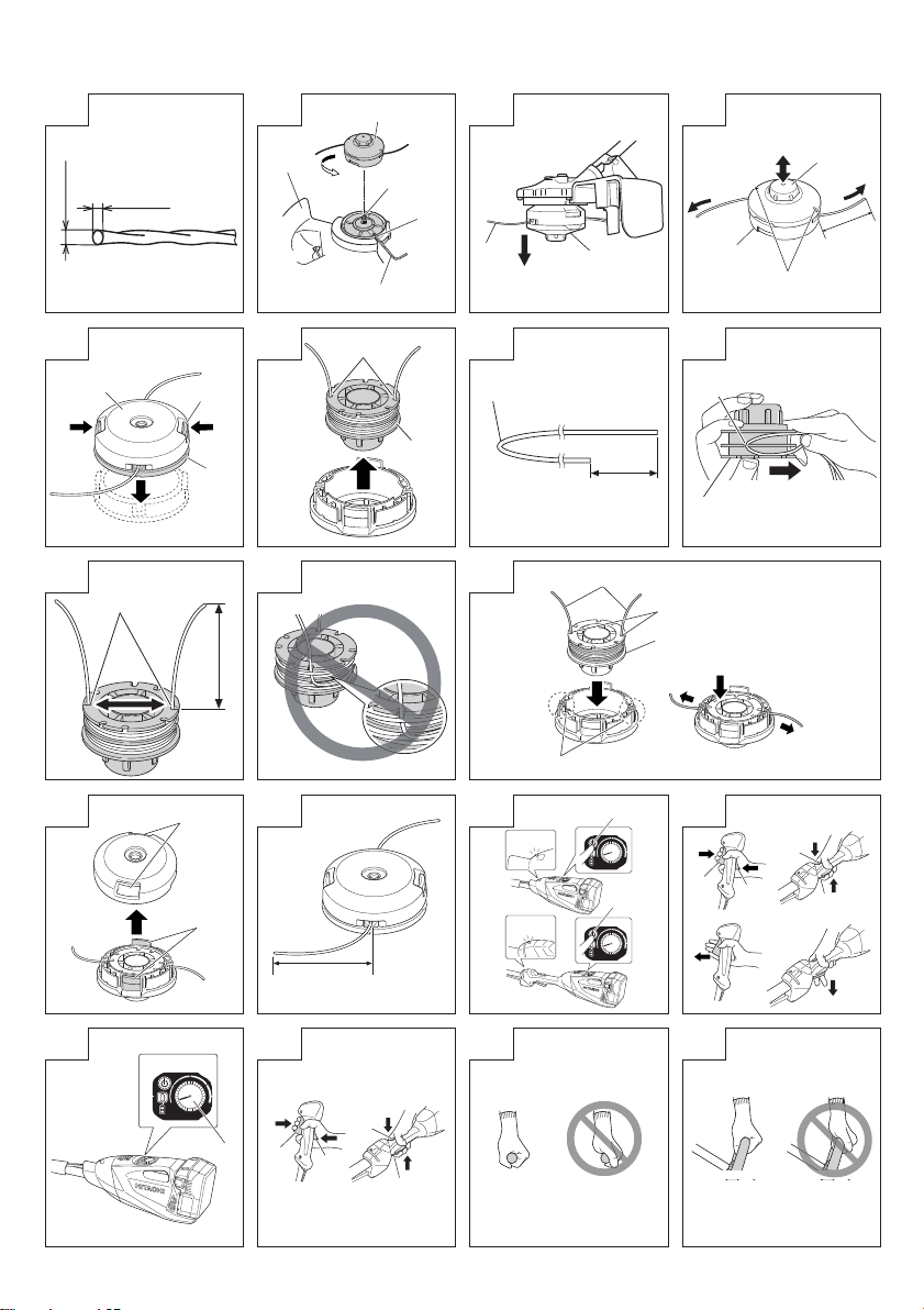
Cord diameter: Fig. 21
Length: 4 m
CAUTION
◯ The case must be securely attached to the cover.
◯ Check the cover, case and other components for cracks
◯ Check the case and button for wear.
If the wear limit mark on the case is no longer visible or
◯ The nylon head must be securely mounted to the
◯ For outstanding performance and reliability, always
◯ If the nylon head does not feed cutting line properly,
2. Installation (Fig. 17 and 22)
(1) Insert the fl ange assy into the motor case. At this time,
(2) Screw the nylon head directly to the threaded fastener of
The mounting nut of nylon head is left-hand-threaded.
CAUTION
Install the nylon head properly and securely as instructed
If not attached properly or securely, it may come off and
3. Adjustment of line length
Rotate and tap the nylon head on the ground. Nylon line
Also, you can extend nylon line with hands. This time the
Confi rm the line extends in 30 mm increments by
◯ Appropriate Length of Nylon Line
The appropriate length of the line when the tool is in use
4. Nylon line replacement
(1) Prepare 4m of genuine nylon line in Fig. 21. (Code No.
(2) Press the opposing tabs, and then remove the cover
(3) Remove the reel from the case. (Fig. 26)
◯ If there is nylon line remaining, hook the line in the groves,
Type of
attaching
screw
Female
screw
or other damage.
there is a hole in the bottom of the button, change the
new parts immediately. (Fig. 24)
threaded fastener of the motor case.
use Hitachi nylon cutting line. Never use wire or other
materials that could become a dangerous projectile.
check that the nylon line and all components are properly
installed. Contact your Hitachi dealer if you need
assistance.
the wing of the fl ange assy should face the motor case
side. Next, align the holes of the fl ange assy and the
motor case, insert the hex. bar wrench 4 mm, and then
turn to tighten the fl ange assy.
the motor case.
Turn clockwise to loosen/ counterclockwise to tighten.
in the handling instructions.
cause injury.
is drawn out abt, 30 mm by one tapping. (Fig. 23)
motor must be completely stopped.
“tapping” and “releasing” the bottom button while pulling
the line ends of the nylon head. (Fig. 24)
is 90 – 110 mm. Extend the line to the appropriate length.
335235)
from the case. (Fig. 25)
and then remove the reel.
Direction of rotation
Counterclockwise
Size of
attaching
screw
M10×
P1.25-LH
20
Page 21

English
◯ If the nylon line does not extend when there is enough
nylon line remaining, or when replacing the nylon
line (Code No. 335235), wind the nylon line using the
following procedure.
(4) Release about 150 mm of the nylon cord from both ends,
fold the middle part and attach to the hook on the spool.
Next, wind the cord on the spool in the direction shown by
the arrow, being careful not to crisscross it (Fig. 27, 28).
(5) Leave about 100 mm – 150 mm nylon cord unwound,
hook and secure the line in the stopper. (Fig. 29)
NOTE
Do not cross the nylon line when securing the line in the
stopper. (Fig. 30)
(6) Align the position of the stopper and eyelet line guide,
and then insert the button through the case.
Release the line from the stopper while holding the reel
lightly, and then string the line through the eyelet line
guide. (Fig. 31)
(7) Press and snap the tabs of the case in the locking holes
of the cover. (Fig. 32)
WARNING
Check to make sure the tabs are fi rmly snapped into the
locking holes.
Operating the tool while the parts are not fi rmly snapped
together may results in accidents or injury from fl ying
part.
(8) Pull the line taught so there is no slack, and then cut
the line to an extended length of 90 mm – 110 mm with
scissors. (Fig. 33)
OPERATION
Trimming grass
WARNING
◯ Do not operate the tool at night or under bad weather
conditions when visibility is poor.
◯ Do not operate the tool when it is raining or right after it
has been raining.
◯ Wear proper footwear to prevent slipping that could
cause you to lose your balance and fall.
◯ Do not use the tool on steep slopes.
When trimming grass on slopes that are not so steep,
trim by moving towards the ridge.
◯ Place the right hand on the handle and the left hand on
the loop handle and hold it fi rmly.
◯ Take care not to move the nylon head too close to your
feet.
◯ Do not raise the nylon head above your knee during
cutting.
◯ Do not use the tool where the nylon head may come into
contact with stones, tree and other obstacles.
◯ A nylon head can injure while it continues to spin after the
motor is stopped. When the unit is turned off , make sure
the nylon head has stopped before the unit is set down.
◯ Do not use the tool within 15 m of another person. When
you work with someone else, maintain a distance of more
than 15 m.
◯ Blade thrust may occur when the spinning blade contacts
a solid object in the critical area.
A dangerous reaction may occur causing the entire unit
and operator to be thrust violently. This reaction is called
blade thrust. As a result, the operator may lose control
of the unit which may cause serious or fatal injury. Blade
thrust is more likely to occur in areas where it is diffi cult to
see the material to be cut.
1. Insert the battery while observing its polarities.
2. Turn on the tool. (Fig. 34)
◯ Press the power button on the housing, the power goes
on and the power lamp on the handle lights red.
◯ Pressing the power button a second time turns the power
off and the red lamp on the handle goes off .
[Auto power off ]
When the power is turned on but the lever is not used for
one minute, the tool is automatically turned off . To turn
the tool on again, press the power button a second time.
WARNING
Never leave the tool with the power on. This could result
in an accident.
3. Lever operation and brake (Fig. 35)
To start rotation of the cutting blade, with the power
turned on, pull the lever while pressing the locking lever.
When you release the lever, the brake engages in 1 – 3
seconds, stopping rotation of the cutting blade.
Make sure that the brake operates normally before using
the tool.
4. Speed dial (Fig. 36)
A speed dial for changing the rotational speed in the
range of 5800 – 7000 min
Turn the dial clockwise to increase the speed and
counterclockwise to reduce the speed.
5. Trimming grass
◯ Grip the handle from above, press the locking lever and
pull the lever to start cutting head rotation. (Fig. 37)
◯ Release the lever when you fi nish trimming and stop the
motor.
◯ Place your thumb on the handle and grip the handle with
your other fi ngers. (Fig. 38) (CG36DL, CG36DAL only)
◯ Place your thumb on the loop handle and grip the handle
with your other fi ngers. (Fig. 39) (CG36DL (L), CG36DAL
(L) only)
◯ Take a posture that makes it easy to move.
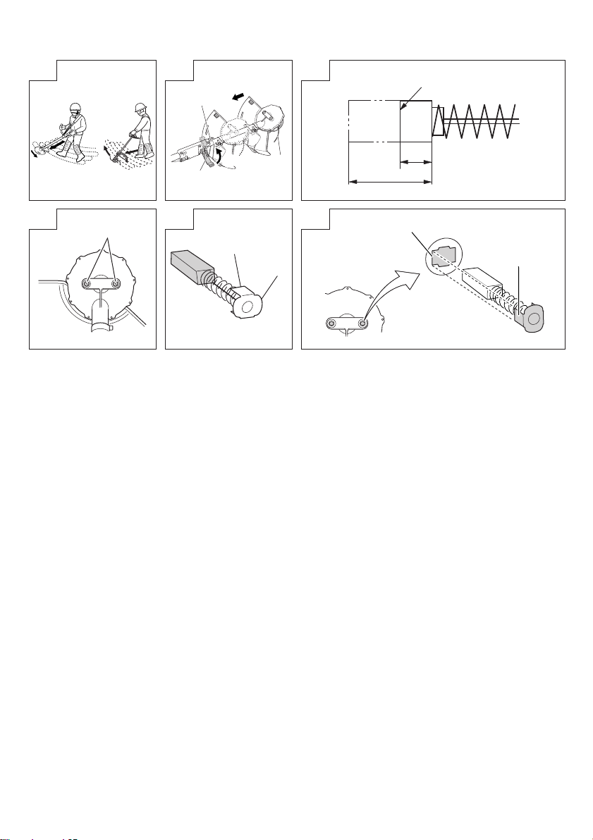
[Grass trimming techniques]
Do not swing the pipe, but use the hips to move the nylon
head horizontally from right to left in an arc while going
forward and use the left side of the nylon head for cutting
grass. (Fig. 40)
-1
is provided on the housing.
OPERATIONAL CAUTIONS
Continuous work
This tool comes with an over-heat protection circuit that
protects the electronic parts that control the rechargeable
battery. In continuous trimming work, tool temperature
will rise and eventually trigger the over-heat protection
circuit, which will shut down the tool.
If this happens, let the tool cool for a length of time. When
the temperature drops, it will again become possible to
use the tool. When the rechargeable battery has to be
exchanged during continuous operation, let the tool rest
for about 15 minutes.
Overload Protection
This tool comes with an overload protection circuit
to protect the electronic parts controlling the tool. In
continuous overload during trimming work (locking the
nylon head, etc.), the overload protection circuit shuts
down the motor. If this happens, turn OFF the power, and
then resolve the problem causing the overload.
The power lamp blinks if the lever is pressed after the
motor has stopped (see page 18, “ABOUT POWER
LAMP”). The power automatically turns OFF if the power
lamp blinks longer than 5 seconds. If this happens,
resolve the problem causing the overload, and then
switch the power button ON to resume using the tool.
Carrying the tool (Fig. 41)
CAUTION
◯ Remove the storage battery and use the cutting blade
cover to protect the cutting blade when carrying the tool.
Carrying the tool without fi rst putting the cutting blade
cover in place exposes the human body to the blade,
which can result in injury.
◯ Carry the tool holding with hands and keeping the cutting
blade away from the body.
21
Page 22

English
◯ When retracting the main pipe, be careful of the
pointed end and take care not get your fi ngers caught.
(CG36DAL, CG36DAL (L) only)
Release the locking lever and retract the main pipe. Lock
the locking lever until the projection hits the main pipe. This
procedure allows you to reduce the tool to a compact size.
The main pipe can be retracted to any position. Choose
a suitable length for carrying and storage. (CG36DAL,
CG36DAL (L) only)
MAINTENANCE AND INSPECTION
CAUTION
Pull out battery before doing any inspection or
maintenance.
1. Checking the condition of the nylon head
The nylon head should be checked regularly. If worn or
broken nylon head can slip or decrease the effi ciency of
the motor and burn it out.
Replace worn nylon head with new ones.
CAUTION
If you use a nylon head of which point is worn or broken,
it will be dangerous. So replace it with a new one.
2. Check the Screws
Loose screws are dangerous. Regularly inspect them
and make sure they are tight.
CAUTION
Using this power tool with loosened screws is extremely
dangerous.
3. Inspecting the carbon brushes (Fig. 42)
The motor employs carbon brushes which are
consumable parts. Since and excessively worn carbon
brush can result in motor trouble, replace the carbon
brush with new ones when it becomes worn to or near
the “wear limit”. In addition, always keep carbon brushes
clean and ensure that they slide freely within the brush
holders.
NOTE
When replacing the carbon brush with a new one, be sure
to use the Hitachi Carbon Brush Code No. 999015.
4. Replacing carbon brushes
Take out the carbon brush by fi rst removing the brush cap
and then hooking the protrusion of the carbon brush with
a slotted head screw driver, etc., as shown in Fig. 43.
When installing the carbon brush, choose the direction
so that the nail of the carbon brush (see Fig. 44) agrees
with the contact portion of brush tube. Then push it in with
a fi nger as illustrated in Fig. 45. Lastly, install the brush
cap.
CAUTION
◯ Be absolutely sure to insert the nail of the carbon brush
into the contact portion of brush tube. (You can insert
whichever one of the two nails provided.)
◯ Caution must be exercised since any error in this
operation can result in the deformed nail of the carbon
brush and may cause motor trouble at an early stage.
5. Cleaning of the outside
When the grass trimmer is stained, wipe with a soft dry
cloth or a cloth moistened with soapy water. Do not use
chloric solvents, gasoline or paint thinner, as they melt
plastics.
6. Storage
Store grass trimmer in a place in which the temperature is
less than 40°C and out of reach of children.
NOTE
Make sure that the battery is fully charged when stored
for a long period (3 months or more). The battery with
smaller capacity may not be able to be charged when
used, if stored for a long period.
NOTE
Storing Lithium-ion Batteries
Make sure the lithium-ion batteries have been fully
charged before storing them.
Prolonged storage of batteries with a low charge may
result in performance deterioration, signifi cantly reducing
battery usage time or rendering the batteries incapable of
holding a charge.
However, signifi cantly reduced battery usage time may
be recovered by repeatedly charging and using the
batteries two to fi ve times.
If the battery usage time is extremely short despite
repeated charging and use, consider the batteries dead
and purchase new batteries.
7. Service parts list
CAUTION
Repair, modifi cation and inspection of Hitachi Power
Tools must be carried out by a Hitachi Authorized Service
Center.
This Parts List will be helpful if presented with the tool to
the Hitachi Authorized Service Center when requesting
repair or other maintenance.
In the operation and maintenance of power tools, the
safety regulations and standards prescribed in each
country must be observed.
MODIFICATIONS
Hitachi Power Tools are constantly being improved
and modifi ed to incorporate the latest technological
advancements.
Accordingly, some parts may be changed without prior
notice.
Important notice on the batteries for the Hitachi
cordless power tools
Please always use one of our designated genuine
batteries. We cannot guarantee the safety and
performance of our cordless power tool when used with
batteries other than these designated by us, or when
the battery is disassembled and modifi ed (such as
disassembly and replacement of cells or other internal
parts).
22
Page 23

TROUBLESHOOTING
Use the inspections in the table below if the tool does not
operate normally. If this does not remedy the problem,
consult your dealer or the Hitachi Authorized Service Center.
Symptom Possible cause Remedy
Charger The Charge lamp does
Tool Does not operate. The rechargeable battery is depleted. Charge the rechargeable battery.
not go on.
Goes on, but soon
stops.
The power plug is not connected to an
AC outlet.
The battery is not properly connected to
the charger.
The battery or charger electrodes are
soiled.
The battery is extremely hot. Allow the battery to properly cool before
The rechargeable battery has not been
properly installed.
The power has not been turned on. Press the power button on the housing
The main pipe is not fully extended
(The red light blinks rapidly) (CG36DAL,
CG36DAL (L) only)
The lock lever was not pressed when the
lever was pulled back.
The tool pulls in large volumes of grass
that are caught between the cover and
the nylon head, the tool is overloaded.
The rechargeable battery power is low. Charge the rechargeable battery.
The rechargeable battery is overheated. Stop using the rechargeable battery,
The locking lever is not locked, causing
the main pipe to shorten up during work.
(The red light blinks rapidly) (CG36DAL,
CG36DAL (L) only)
Connect the power plug to an AC outlet.
Insert the battery so that it is properly
seated in the charger.
Use a cotton swab or other tool to clean
the electrodes.
charging.
Remove the rechargeable battery from
the battery compartment in the tool and
check for and remove any foreign matter.
Also check the battery electrodes for
soiling, water or other foreign matter. Use
a cotton swab for cleaning. Make sure
that the rechargeable battery is pressed
in until it clicks into place.
to start the tool. This tool comes with an
auto power off function. The power is
automatically turned off if nobody pulls
the lever during a one minute period after
power on. To turn the tool on again, press
the power button a second time.
Pressing the power button a second time
turns the power off .
To prevent accidents due to malfunction,
the tool is designed so that the motor will
not operate unless the main pipe is fully
extended.
Extend the main pipe fully until it clicks.
To prevent accidents from incorrect
operation, the lock lever must be pressed
while the lever is pulled back to start the
motor.
Hold the handle from above and press
the lock lever while pulling the handle.
This is the eff ect of a function that
protects the rechargeable battery by
turning off the motor when the tool is
exposed to an excessive load. Turn off
the tool and remove the cause of the
overload. Press the power button once
again to continue operation.
remove it from the tool and let it cool in
a well-ventilated location not exposed to
sunlight.
Lock the locking lever.
English
23
Page 24

English
Symptom Possible cause Remedy
Tool Strong vibrations. The loop handle is not properly attached
The brake fails to
engage 1-3 seconds
after the lever is
released.
GUARANTEE
We guarantee Hitachi Power Tools in accordance with
statutory/country specifi c regulation. This guarantee does
not cover defects or damage due to misuse, abuse, or normal
wear and tear. In case of complaint, please send the Power
Tool, undismantled, with the GUARANTEE CERTIFICATE
found at the end of this Handling instruction, to a Hitachi
Authorized Service Center.
NOTE
Due to HITACHI’s continuing program of research and
development, the specifi cations herein are subject to
change without prior notice.
Information concerning airborne noise and vibration
The measured values were determined according to
IEC60335 and declared in accordance with ISO 4871.
Measured A-weighted sound power level: 85 dB (A).
Measured A-weighted sound pressure level: 76 dB (A).
Uncertainty KpA: 3 dB (A).
Wear hearing protection.
Vibration total values (triax vector sum) determined
according to IEC60335.
Vibration emission value
ah. w = 4 m/s
to the main pipe.
The cover is not been properly attached
to the main pipe.
This may be due to a malfunction of the
tool.
2
Secure properly.
Secure properly.
Contact the store where you purchased
the tool or your nearest Hitachi
Authorized Service Center.
The declared vibration total value has been measured in
accordance with a standard test method and may be used
for comparing one tool with another.
It may also be used in a preliminary assessment of exposure.
WARNING
◯ The vibration emission during actual use of the power
tool can diff er from the declared total value depending on
the ways in which the tool is used.
◯ Identify safety measures to protect the operator that
are based on an estimation of exposure in the actual
conditions of use (taking account of all parts of the
operating cycle such as the times when the tool is
switched off and when it is running idle in addition to the
trigger time).
24
Page 25
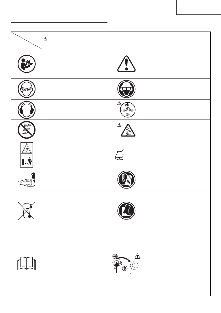
SYMBOLBEDEUTUNGEN
Symbole
WARNUNG
Die folgenden Symbole werden für diese Maschine verwendet. Achten Sie darauf, diese vor der
Verwendung zu verstehen.
Lesen Sie sämtliche
Sicherheitshinweise und
Anweisungen durch.
Wenn die Warnungen und Anweisungen
nicht befolgt werden, kann es zu
Stromschlag, Brand und/oder
ernsthaften Verletzungen kommen.
Tragen Sie immer einen Augenschutz.
Stets Gehörschutz tragen.
(Übersetzung der Original-Gebrauchsanweisung)
Lesen, verstehen und befolgen Sie alle
Warnungen und Anweisungen in dieser
Anleitung und am Gerät selbst.
Bei Gebrauch des Geräts immer
Gesichts-, Kopf- und Gehörschutz
tragen.
Kinder und Zuschauer in einem Abstand
von 15 m vom Gerät halten. Stoppen Sie
das Gerät und die Schneideinheit sofort,
wenn sich Ihnen jemand nähert.
Deutsch
Keiner Feuchtigkeit aussetzen.
Achten Sie darauf, dass keine
unbeteiligten Personen in der Nähe sind.
Entfernen Sie die Batterie vor dem
Einstellen und der Reinigung sowie
dann, wenn das Gerät unbeaufsichtigt
ist.
Nur für EU-Länder
Werfen Sie Elektrowerkzeuge nicht in
den Hausmüll!
Gemäss Europäischer Richtlinie
2002/96/EG über Elektro- und
Elektronik- Altgeräte und Umsetzung in
nationales Recht müssen verbrauchte
Elektrowerkzeuge getrennt gesammelt
und einer umweltgerechaten
Wiederververtung zugeführt werden.
Es ist wichtig, dass Sie sich mit den
nachfolgenden Vorsichtsmaßnahmen
und Warnungen vertraut machen und
diese befolgen. Unvorsichtige oder
unsachgemäße Handhabung des
Geräts kann schwere oder tödliche
Verletzungen zur Folge haben.
Max
8,000 min
Auf hochgeschleuderte Gegenstände
achten.
Zeigt die maximale Drehzahl
der Welle an. Verwenden Sie
kein Schneidzubehör, dessen
-1
Maximaldrehzahl unter diesem Wert
liegt.
Handschuhe sind dann zu tragen, wenn
dies notwendig ist, z.B. bei der Montage
der Schneidausrüstung.
Rutschfestes Schuhwerk tragen, das
guten Halt bietet.
Ein Messerstoß ist möglich, wenn das
rotierende Messer im kritischen Bereich
mit einem massiven Gegenstand in
Berührung kommt. In diesem Fall kann
es zu einer gefährlichen Reaktion
kommen, bei der das gesamte Gerät
und der Bediener einem heftigen Stoß
ausgesetzt werden. Diese Reaktion
wird als Messerstoß bezeichnet. Das
Resultat ist u.U., dass der Bediener
die Kontrolle über das Gerät verliert
und schwere oder lebensgefährliche
Verletzungen davonträgt. Messerstöße
sind in Arbeitsbereichen, wo das zu
schneidende Vegetationsmaterial nur
schwer einsehbar ist, wahrscheinlicher.
25
Page 26
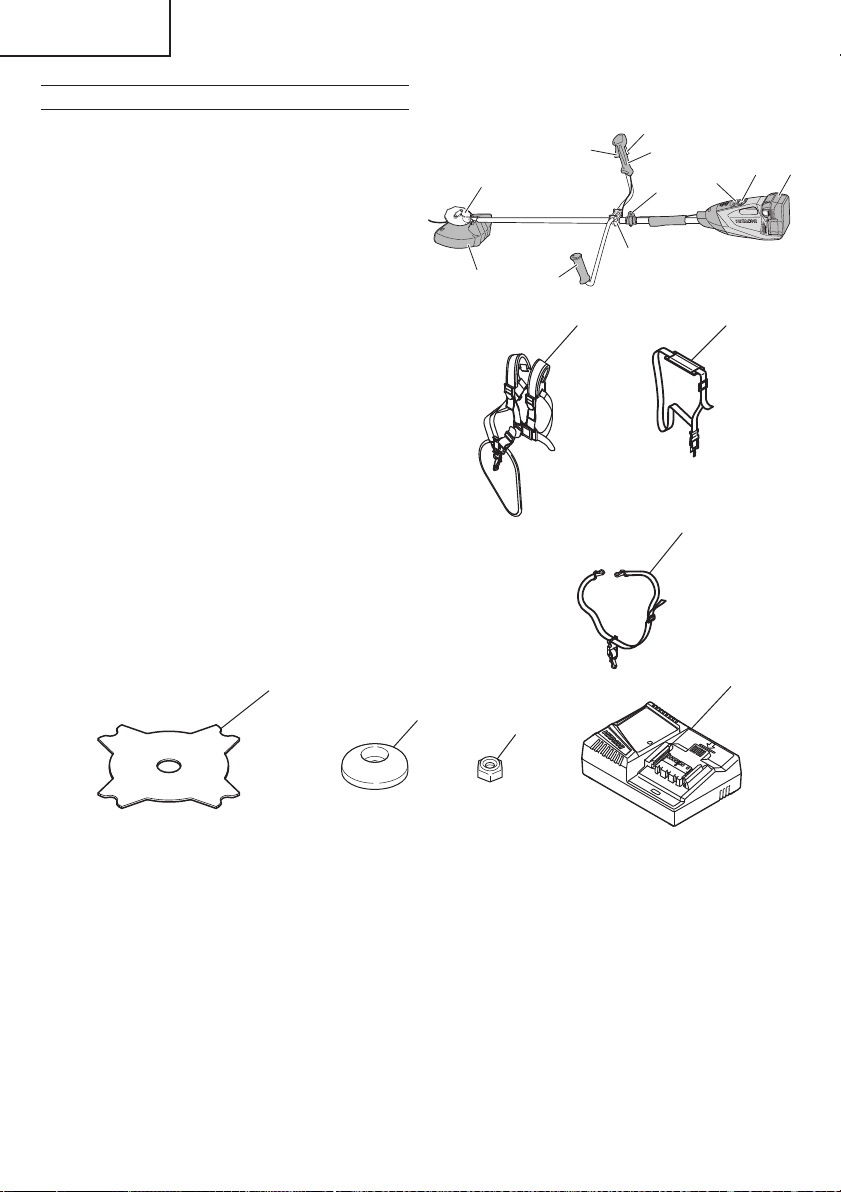
Deutsch
TEILEBEZEICHNUNGEN
1. Hebel: Auslöser zum Aktivieren des Gerätes.
2. Verriegelungshebel: Hebel, der ein unbeabsichtigtes
Betätigen des Auslösers verhindert.
3. Motor: Batteriebetriebener, scheibenförmiger Motor.
4. Abdeckung: Schützt den Bediener vor herumfl iegenden
Trümmern.
5. Batterie: Energiequelle für den Antrieb des Gerätes.
6. Einschalttaste: Taste zum Ein-/Ausschalten des Gerätes.
7. Geschwindigkeitswählschalter: Wählschalter zum
Einstellen der Motordrehzahl.
8. Griff rechts: Griff mit Hebel an der rechten Seite des
Gerätes.
9. Griff links: Griff an der rechten Seite des Gerätes.
10. Griff einbau: Befestigung des Griff s am Gerät.
11. Hänger: Zum Anbringen eines Schulter- oder
Hängeriemens am Gerät.
12. Schulterriemen: Gurtzeug mit Lösemechanismus zur
Benutzung zusammen mit einer Batterie.
13. Hängeriemen: Gurtzeug mit Lösemechanismus
zur Benutzung zusammen mit rückentragbarer
Spannungsversorgung.
14. Klinge (optionale Zubehöre): Metallklingen-
Schneidewerkzeug
15. Mutterabdeckung (optionale Zubehöre): Hält die Klinge
nach unten.
16. Linke M10 Installationsmutter (optionale Zubehöre): Zum
Befestigen der Klinge am Gerät.
17. Ladegerät: Zum Aufl aden der Batterie.
1
3
4
9
2
8
6
11
10
CG36DL
1212
13
5
7
14
15
26
16
17
Page 27

Deutsch
ALLGEMEINE SICHERHEITSHINWEISE FÜR
ELEKTROGERÄTE
WARNUNG
Lesen Sie sämtliche Sicherheitshinweise und
Anweisungen durch.
Wenn die Warnungen und Anweisungen nicht befolgt
werden, kann es zu Stromschlag, Brand und/oder
ernsthaften Verletzungen kommen.
Bitte bewahren Sie alle Warnhinweise und Anweisungen
zum späteren Nachschlagen auf.
er Begriff „Elektrowerkzeug“ bezieht sich in den
Warnhinweisen auf Elektrowerkzeuge mit Netz(schnurgebunden) oder Akkubetrieb (schnurlos).
1) Sicherheit im Arbeitsbereich
a) Sorgen Sie für einen sauberen und gut
ausgeleuchteten Arbeitsbereich.
Zugestellte oder dunkle Bereiche ziehen Unfälle
förmlich an.
b) Verwenden Sie Elektrowerkzeuge niemals an
Orten, an denen Explosionsgefahr besteht – zum
Beispiel in der Nähe von leicht entfl ammbaren
Flüssigkeiten, Gasen oder Stäuben.
Bei der Arbeit mit Elektrowerkzeugen kann es zu
Funkenbildung kommen, wodurch sich Stäube oder
Dämpfe entzünden können.
c) Sorgen Sie bei der Arbeit mit Elektrowerkzeugen
dafür, dass sich keine Zuschauer (insbesondere
Kinder) in der Nähe befi nden.
Wenn Sie abgelenkt werden, können Sie die
Kontrolle über das Werkzeug verlieren.
2) Elektrische Sicherheit
a) Elektrowerkzeuge müssen mit passender
Stromversorgung betrieben werden.
Nehmen Sie niemals irgendwelche Änderungen
am Anschlussstecker vor.
Verwenden Sie bei Elektrowerkzeugen
mit Schutzkontakt (geerdet) niemals
Adapterstecker.
Stecker im Originalzustand und passende
Steckdosen reduzieren das Stromschlagrisiko.
b) Vermeiden Sie Körperkontakt mit geerdeten
Gegenständen wie Rohrleitungen, Heizungen,
Herden oder Kühlschränken.
Bei Körperkontakt mit geerdeten Gegenständen
besteht ein erhöhtes Stromschlagrisiko.
c) Setzen Sie Elektrowerkzeuge niemals Regen
oder sonstiger Feuchtigkeit aus.
Wenn Flüssigkeiten in ein Elektrowerkzeug
eindringen, erhöht sich das Stromschlagrisiko.
d) Verwenden Sie das Anschlusskabel
nicht missbräuchlich. Tragen Sie
das Elektrowerkzeug niemals an der
Anschlussschnur, ziehen Sie es nicht damit
heran und ziehen Sie den Stecker nicht an der
Anschlussschnur aus der Steckdose.
Halten Sie die Anschlussschnur von Hitzequellen,
Öl, scharfen Kanten und beweglichen Teilen
fern.
Beschädigte oder verdrehte Anschlussschnüre
erhöhen das Stromschlagrisiko.
e) Wenn Sie ein Elektrowerkzeug im Freien
benutzen, verwenden Sie ein für den
Außeneinsatz geeignetes Verlängerungskabel.
Ein für den Außeneinsatz geeignetes Kabel
vermindert das Stromschlagrisiko.
f) Falls sich der Betrieb des Elektrowerkzeuges
in feuchter Umgebung nicht vermeiden lässt,
verwenden Sie eine Stromversorgung mit
Fehlerstromschutzeinrichtung (Residual
Current Device, RCD).
Durch den Einsatz einer Fehlerstromschutzeinrichtung
wird das Risiko eines elektrischen Schlages
reduziert.
3) Persönliche Sicherheit
a) Bleiben Sie wachsam, achten Sie auf das, was
Sie tun, und setzen Sie Ihren Verstand ein, wenn
Sie mit Elektrowerkzeugen arbeiten.
Benutzen Sie keine Elektrowerkzeuge, wenn
Sie müde sind oder unter Einfl uss von Drogen,
Alkohol oder Medikamenten stehen.
Bei der Arbeit mit Elektrowerkzeugen können bereits
kurze Phasen der Unaufmerksamkeit zu schweren
Verletzungen führen.
b) Benutzen Sie eine persönliche
Schutzausrüstung. Tragen Sie immer einen
Augenschutz.
Schutzausrüstung wie Staubmaske, rutschsichere
Sicherheitsschuhe, Schutzhelm und Gehörschutz
senken das Verletzungsrisiko bei angemessenem
Einsatz.
c) Vermeiden Sie unbeabsichtigtes Einschalten.
Achten Sie darauf, dass sich der Schalter
in der Aus- (Off -) Position befi ndet, ehe Sie
das Gerät mit der Stromversorgung und/
oder Batteriestromversorgung verbinden, es
aufheben oder herumtragen.
Das Herumtragen von Elektrowerkzeugen mit
dem Finger am Schalter oder das Herstellen der
Stromversorgung bei betätigtem Schalter zieht
Unfälle regelrecht an.
d) Entfernen Sie sämtliche Einstellwerkzeuge
(Einstellschlüssel), ehe Sie das
Elektrowerkzeug einschalten.
Ein an einem beweglichen Teil des Elektrowerkzeugs
angebrachter Schlüssel kann zu Verletzungen
führen.
e) Sorgen Sie für einen festen Stand. Achten Sie
jederzeit darauf, sicher zu stehen und das
Gleichgewicht zu bewahren.
Dadurch haben Sie das Elektrowerkzeug in
unerwarteten Situationen besser im Griff .
f) Kleiden Sie sich richtig. Tragen Sie keine lose
Kleidung oder Schmuck. Halten Sie Haar,
Kleidung und Handschuhe von beweglichen
Teilen fern.
Lose Kleidung, Schmuck oder langes Haar kann von
beweglichen Teilen erfasst werden.
g) Wenn Anschlüsse für Staubabsaug- und -
sammelvorrichtungen vorhanden sind, sorgen
Sie dafür, dass diese richtig angeschlossen und
eingesetzt werden.
Durch Entfernen des Staubes können staubbezogene
Gefahren vermindert werden.
4) Einsatz und Pfl ege von Elektrowerkzeugen
a) Überanspruchen Sie Elektrowerkzeuge nicht.
Benutzen Sie das richtige Elektrowerkzeug für
Ihren Einsatzzweck.
Das richtige Elektrowerkzeug erledigt seine Arbeit bei
bestimmungsgemäßem Einsatz besser und sicherer.
b) Benutzen Sie das Elektrowerkzeug nicht, wenn
es sich nicht am Schalter ein- und ausschalten
lässt.
Jedes Elektrowerkzeug, das nicht mit dem Schalter
betätigt werden kann, stellt eine Gefahr dar und muss
repariert werden.
27
Page 28

Deutsch
c) Stecken Sie den Stecker der Stromversorgung
oder Batteriestromversorgung vom Gerät ab, ehe
Sie Einstellarbeiten vornehmen, Zubehörteile
tauschen oder das Elektrowerkzeug verstauen.
Solche präventiven Sicherheitsmaßnahmen
verhindern den unbeabsichtigten Anlauf des
Elektrowerkzeugs und die damit verbundenen
Gefahren.
d) Lagern Sie nicht benutzte Elektrowerkzeuge
außerhalb der Reichweite von Kindern, lassen
Sie nicht zu, dass Personen das Elektrowerkzeug
bedienen, die nicht mit dem Werkzeug selbst
und/oder diesen Anweisungen vertraut sind.
Elektrowerkzeuge in ungeschulten Händen sind
gefährlich.
e) Halten Sie Elektrowerkzeuge in Stand. Prüfen
Sie auf Fehlausrichtungen, sicheren Halt
und Leichtgängigkeit beweglicher Teile,
Beschädigungen von Teilen und auf jegliche
andere Zustände, die sich auf den Betrieb des
Elektrowerkzeugs auswirken können.
Bei Beschädigungen lassen Sie das
Elektrowerkzeug reparieren, ehe Sie es
benutzen.
Viele Unfälle mit Elektrowerkzeugen sind auf
schlechte Wartung zurückzuführen.
f) Halten Sie Schneidwerkzeuge scharf und
sauber.
Richtig gewartete Schneidwerkzeuge mit scharfen
Schneidkanten bleiben weniger häufi g hängen und
sind einfacher zu beherrschen.
g) Benutzen Sie Elektrowerkzeuge,
Zubehör, Werkzeugspitzen und Ähnliches
in Übereinstimmung mit diesen
Anweisungen – beachten Sie dabei die jeweiligen
Arbeitsbedingungen und die Art und Weise der
auszuführenden Arbeiten.
Der Gebrauch des Elektrowerkzeuges für andere
als die vorgesehenen Anwendungen kann zu
gefährlichen Situationen führen.
5) Verwendung und Pfl ege der Batterie
a) Laden Sie das Gerät nur mit dem vom Hersteller
empfohlenen Ladegerät auf.
Ein Ladegerät für einen speziellen Batterietyp kann
bei Verwendung mit anderen Batterien zu Gefahren
führen.
b) Verwenden Sie für das Gerät nur die speziell
empfohlenen Batterien.
Eine Verwendung von anderen Batterien kann zu
Verletzungen und Bränden führen.
c) Ist die Batterie nicht in Gebrauch, achten
Sie darauf, dass sie nicht mit metallischen
Gegenständen, beispielsweise Büroklammern,
Münzen, Schlüssel, Nägel, Schrauben in
Kontakt kommt, da diese Gegenstände einen
Kurzschluss der Anschlüsse verursachen
könnten.
Ein Kurzschluss der Batterieanschlüsse kann zu
Verbrennungen oder Bränden führen.
d) Im Falle von Störungen, kann Flüssigkeit aus der
Batterie austreten. Vermeiden Sie in diesem Fall
jeglichen Kontakt. Sollten Sie dennoch mit der
Batterie in Berührung kommen, waschen Sie die
betroff ene Stelle gründlich mit Wasser ab. Ist die
Flüssigkeit ins Auge geraten, suchen Sie einen
Arzt auf.
Ausgetretene Batteriefl üssigkeiten können zu
Reizungen oder Verbrennungen führen.
6) Service
a) Lassen Sie Elektrowerkzeuge durch qualifi zierte
Fachkräfte und unter Einsatz passender,
zugelassener Originalteile warten.
Dies sorgt dafür, dass die Sicherheit des
Elektrowerkzeugs nicht beeinträchtigt wird.
VORSICHT
Von Kindern und gebrechlichen Personen fernhalten.
Werkzeuge sollten bei Nichtgebrauch außerhalb der
Reichweite von Kindern und gebrechlichen Personen
aufbewahrt werden.
RASENTRIMMER-SICHERHEITSHINWEISE
WICHTIG
VOR VERWENDUNG SORGFÄLTIG LESEN
FÜR KÜNFTIGE BEZUGNAHME AUFBEWAHREN
Maßnahmen zur sicheren Bedienung
● Vertrautmachen
a) Lesen Sie die Anleitung sorgfältig durch. Machen Sie sich
mit den Steuerelementen und der korrekten Bedienung
des Geräts vertraut.
b) Gestatten Sie Personen, die nicht mit dieser Anleitung
vertraut sind oder Kindern nie die Bedienung des Geräts.
Das Mindestalter zur Bedienung des Geräts kann durch
örtliche Vorschriften festgelegt sein.
c) Bedenken Sie, dass der Bediener oder Benutzer des
Geräts für Unfälle oder Verletzungen anderer Personen
oder Beschädigung von deren Eigentum verantwortlich
ist.
● Vorbereitung
a) Betätigen Sie das Gerät nie, wenn sich Personen,
insbesondere Kinder, oder Tiere in der Nähe befi nden.
b) Tragen Sie beim Betreiben der Maschine immer
Schutzbrille, Handschuhe und festes Schuhwerk.
● Betrieb
a) Verwenden Sie das Gerät ausschließlich bei Tageslicht
oder ausreichender künstlicher Beleuchtung.
b) Betätigen Sie das Gerät nie mit beschädigten oder nicht
angebrachten Abdeckungen oder Schutzvorrichtungen.
c) Schalten Sie den Motor nur ein, wenn sich Hände
und Füße nicht in der Nähe der Schneidevorrichtung
befi nden.
d) Unterbrechen Sie immer die Stromversorgung des Geräts
(d. h. ziehen Sie den Stecker aus der Netzsteckdose
oder entfernen Sie die Sperrvorrichtung)
– wenn Sie das Gerät unbeaufsichtigt lassen;
– bevor Sie eingeklemmtes Material entfernen;
– bevor Sie das Gerät inspizieren, reinigen oder
Arbeiten am Gerät vornehmen;
– nach Kontakt mit einem Fremdkörper;
– wenn das Gerät ungewöhnlich stark zu vibrieren
beginnt.
e) Schützen Sie sich vor Verletzungen der Füße und Hände
durch die Schneidevorrichtung.
f) Vergewissern Sie sicher, dass die Lüftungsöff nungen
stets frei von Rückständen sind.
g) Keinesfalls das Gerät in irgendeiner Weise abändern.
Das Schneidwerkzeug nur für die Zwecke verwenden,
für die es bestimmt ist.
● Wartung, Transport und Lagerung
a) Unterbrechen Sie immer die Stromversorgung des Geräts
(d. h. ziehen Sie den Stecker aus der Netzsteckdose
oder entfernen Sie die Sperrvorrichtung), bevor Sie
Wartungs- oder Reinigungsarbeiten durchführen.
b) Verwenden Sie ausschließlich die durch den Hersteller
empfohlenen Ersatz- und Zubehörteile.
28
Page 29

Deutsch
c) Führen Sie in regelmäßigen Abständen Inspektions-
und Wartungsarbeiten durch. Lassen Sie Reparaturen
des Geräts ausschließlich durch eine Vertragswerkstatt
durchführen.
d) Bewahren Sie das Gerät, wenn es nicht verwendet wird,
außerhalb der Reichweite von Kindern auf.
e) Schützen sie die Klinge mit einem Klingenschutz beim
Transport in einem Fahrzeug bzw. zum Lagern.
VORSICHTSMASSNAHMEN BEIM AKKURASENTRIMMER
WARNUNG
1. Bei der Arbeit mit dem Gerät stets gelassen bleiben.
Zum Schutz vor Kälte angemessene Kleidung tragen.
2. Vorausschauend arbeiten, um Unfälle zu vermeiden.
3. Das Gerät nicht bei Nacht oder schlechten
Witterungsverhältnissen mit eingeschränkter Sicht
bedienen. Das Gerät zudem nicht bei Regen oder kurz
nach einem Regenschauer betätigen.
Arbeit auf rutschigem Untergrund kann zu Unfällen
führen, wenn Sie das Gleichgewicht verlieren.
4. Den Nylonkopf vor Inbetriebnahme des Geräts
inspizieren.
Das Gerät nicht verwenden, wenn der Nylonkopf Risse,
Schrammen oder Verbiegungen aufweist.
Es ist darauf zu achten, dass der Nylonkopf
ordnungsgemäß angebracht ist. Ein während der Arbeit
auseinanderfallender oder sich lösender Nylonkopf kann
zu Unfällen führen.
5. Vor Arbeitsbeginn sicherstellen, dass die Abdeckung
angebracht ist.
6. Es ist darauf zu achten, dass der Bügelgriff vor
Arbeitsbeginn angebracht ist. Vor Inbetriebnahme
des Geräts sicherstellen, dass er nicht locker sitzt und
ordnungsgemäß angebracht ist. Das Gerät während
der Arbeit fest am Bügelgriff halten und das Gerät nicht
umherschwenken, sondern bei festem Stand die korrekte
Körperhaltung einnehmen.
Ein Gleichgewichtsverlust während der Arbeit kann zu
Verletzungen führen.
7. Beim Starten des Motors entsprechende Vorsicht walten
lassen.
Das Gerät auf ebenem Untergrund ablegen.
Bei der Betätigung des Geräts einen Mindestabstand
von 15 m zu anderen Personen oder Tieren einhalten.
Es ist darauf zu achten, dass der Nylonkopf nicht mit dem
Boden oder Bäumen und Pfl anzen in Berührung kommt.
Ein unachtsames Starten des Geräts kann zu
Verletzungen führen.
8. Den Verriegelungshebel nicht fi xieren.
Ein versehentliches Zurückziehen des Hebels kann zu
Verletzungen führen.
9. Vor dem Verlassen des Geräts dieses durch Betätigung
des Einschaltknopfs ausschalten.
10. Bei der Betätigung des Geräts in der Nähe von
Stromkabeln, Gasleitungen und ähnlichen Installationen
mit äußerster Vorsicht vorgehen.
11. Vor Arbeitsbeginn leere Dosen, Draht, Steine und
andere Hindernissen entfernen. Nicht in der Nähe großer
Wurzeln oder Felsen arbeiten.
Das Arbeiten in solchen Bereichen kann zur
Beschädigung des Nylonkopfes führen und Verletzungen
zur Folge haben.
12. Den Nylonkopf während des Betriebs niemals anfassen.
Zudem ist darauf zu achten, dass er nicht mit Haar,
Kleidung etc. in Berührung kommt.
13. In den folgenden Situationen den Motor abstellen und
kontrollieren, ob der Nylonkopf aufgehört hat, sich zu
drehen.
Um zu einem neuen Arbeitsbereich zu wechseln.
Um Fremdkörper oder Gras zu entfernen, die sich im
Gerät verfangen haben.
Um Hindernisse oder durch die Arbeit angefallene
Schnittabfälle, Grass oder Späne aus dem Arbeitsbereich
zu entfernen.
Um das Gerät abzulegen.
Die Durchführung dieser Tätigkeiten bei rotierendem
Nylonkopf kann zu Unfällen führen.
14. Bei der Betätigung des Geräts einen Mindestabstand
von 15 m zu anderen Personen einhalten.
Bei gemeinsamer Arbeit mit einer anderen Person einen
Mindestabstand von mehr als 15 m einhalten.
Hochgeschleuderte Späne können zu Unfällen führen.
Bei der Arbeit auf unebenen Untergründen wie an
Hängen ist darauf zu achten, dass die mit Ihnen
arbeitende Person keinen Gefahren ausgesetzt wird.
Mitarbeiter mit Hilfe von Pfeifen oder anderen Mitteln auf
mögliche Gefahren aufmerksam machen.
15. Wenn sich Gras oder andere Fremdkörper im Nylonkopf
verfangen haben, den Motor abstellen und sichergehen,
dass sich der Nylonkopf nicht mehr dreht, bevor diese
entfernt werden.
Das Entfernen von Fremdkörpern aus einem rotierenden
Nylonkopf führt zu Verletzungen.
Das Fortsetzen der Arbeit, wenn sich Fremdkörper im
Nylonkopf verfangen haben, kann zur Beschädigung des
Geräts führen.
16. Bei schwacher Geräteleistung oder seltsamen
Geräuschen oder Vibrationen des Geräts den Motor
sofort abstellen und das Gerät durch Ihren Fachhändler
inspizieren und reparieren lassen.
Eine weitere Verwendung in diesem Zustand kann zu
Verletzungen oder der Beschädigung des Geräts führen.
17. Das Gerät nach versehentlichem Fallenlassen oder
Anstoßen sorgfältig inspizieren, um sicherzustellen, dass
keine Schäden, Risse oder Verformungen aufgetreten
sind.
Die Verwendung eines beschädigten, rissigen oder
deformierten Geräts kann Verletzungen zur Folge haben.
18. Das Gerät beim Transport in einem Fahrzeug sichern,
um ein Umherrutschen zu vermeiden.
Das Nichtbefolgen dieser Warnung kann zu Unfällen
führen.
19. Im Motor dieses Produkts befi ndet sich ein starker
Dauermagnet.
Beachten Sie die folgenden Vorsichtsmaßnahmen
hinsichtlich Anhaftung von Spänen am Werkzeug und
die Auswirkung des Dauermagneten auf elektronische
Geräte.
VORSICHT
◯ Legen Sie das Werkzeug nicht auf eine Werkbank oder
in einen Bereich, wo Metallspäne vorhanden sind.
Die Späne können am Werkzeug anhaften und
Verletzungen oder Geräteausfall verursachen.
◯ Wenn Späne am Werkzeug anhaften, dürfen Sie es nicht
anfassen.
Entfernen Sie die Späne mit einer Bürste.
Andernfalls können Verletzungen erfolgen.
◯ Verwenden Sie einen Herzschrittmacher oder ein
anderes elektronisches Medizinprodukt, dürfen Sie sich
dem Werkzeug nicht nähern oder es gar bedienen.
Der Betrieb des Elektronikgeräts kann beeinträchtigt
werden.
◯ Verwenden Sie das Werkzeug nicht in der Nähe von
Präzisionsgeräten, z. B. Handys, Magnetkarten oder
elektronischen Speichermedien.
Andernfalls kann dies zu Fehlfunktionen, Geräteausfall
oder Datenverlust führen.
29
Page 30

Deutsch
VORSICHT
1. Den Nylonkopf ausschließlich zum Schneiden von Gras
verwenden. Das Gerät nicht in Pfützen verwenden
und sicherstellen, dass der Nylonkopf nicht mit Erde in
Berührung kommt.
2. Das Gerät enthält Präzisionsteile und sollte nicht
fallengelassen oder heftigen Stößen oder Wasser
ausgesetzt werden.
Anderenfalls können Schäden oder Funktionsstörungen
des Geräts auftreten.
3. Bei der Lagerung nach der Verwendung oder dem
Transport des Geräts den Nylonkopf entfernen.
4. Das Gerät nicht mit Insektenvernichtungsmitteln oder
anderen Chemikalien in Berührung bringen.
Solche Chemikalien können zu Rissbildung und anderen
Schäden führen.
5. Warnhinweise durch neue ersetzen, wenn sie undeutlich
oder unlesbar werden oder sich abzulösen beginnen.
Warnhinweisetiketten erhalten Sie bei Ihrem
Fachhändler.
6. Sie dürfen den Motor nicht gleich nach dem Betrieb
anfassen, da er sehr heiß werden kann.
VORSICHTSMASSNAHMEN FÜR BATTERIE
UND LADEGERÄT
1. Die Batterie immer bei einer Temperatur von 0°C –
40°C laden. Laden bei einer Temperatur, die nied riger
als 0°C ist, wird gefährliche Überladung ver ursachen.
die Batterie kann nicht bei einer Tem peratur über 40°C
geladen werden. Die beste Temperatur zum Laden wäre
von 20°C – 25°C.
2. Nach Beendung einer Ladung, lassen Sie das
Ladegerät ungefähr 15 Minuten ruhen bevor die nächste
Batterieladung unternommen wird.
Nicht mehr als zwei Batterien hintereinander laden.
3. Keine Fremdkörper durch das Anschlußloch der Batterie
eindringen lassen.
4. Darauf achten, daß keine Gegenstände durch
Belüftungsschlitze das Ladegeräts in das Gerät
eindringen. Wenn Metallobjekte oder entzündliche
Gegenstände durch die Belüftungsschlitze des
Ladegeräts eindringen, kann dies zu elektrischen
Schlägen führen oder das Ladegerät beschädigen.
5. Das Benutzen einer leeren Batterie beschädigt das
Ladegerät.
6. Bringen Sie die Batterie zum Geschäft, wo Sie sie
gekauft haben, sobald die Lebensdauer der Batterie zur
Neige geht. Die leere Batterie nicht wegwerfen.
7. Niemals die Batterie und das Ladegerät auseinandernehmen.
8. Niemals die Batterie kurzschließen. Kurzschluß der
Batterie verursacht eine zu große Stromzufuhr und
überhitzung, wodurch Durch brennen oder Schaden
beider Batterie entsteht.
9. Die Batterie nicht ins Feuer werfen. Sie könnte dabei
explodieren.
WARNUNG ZUM LITHIUM-IONEN-AKKU
Um die Lebensdauer des Lithium-Ionen-Akkus zu
verlängern, ist dieser mit einer Schutzfunktion zum Stoppen
der Leistungsabgabe ausgestattet.
In den unten beschriebenen Fällen 1 bis 3 kann bei der
Benutzung dieses Produkts der Motor abschalten, selbst
wenn Sie den Schalter drücken. Dies ist kein Defekt sondern
das Resultat der Schutzfunktion.
1. Wenn die verbleibende Akkuleistung nicht mehr
ausreicht, schaltet der Motor ab.
Laden Sie in einem solchen Fall den Akku umgehend
auf.
30
2. Wenn das Werkzeug überlastet ist, kann es zum
Abschalten des Motors kommen. Lassen Sie in diesem
Fall den Schalter des Geräts los und beseitigen Sie die
Ursache der Überlastung. Danach können Sie das Gerät
wieder verwenden.
3. Kommt es während des Betriebs zu einer Erhitzung der
Batterie, wird das Gerät unter Umständen angehalten.
Unterbrechen Sie in diesem Fall Ihre Arbeit und lassen
Sie die Batterie abkühlen. Anschließend können Sie das
Gerät wieder normal verwenden.
Bitte beachten Sie die folgenden Warnhinweise.
WARNUNG
Zur Vermeidung einer ausgelaufenen Batterie, Erwärmung,
Rauchentwicklung, Explosionen und vorzeitiger Zündung
beachten Sie bitte die folgenden Vorsichtsmaßnahmen.
1. Stellen Sie sicher, dass sich Späne und Staub nicht auf
der Batterie ansammeln.
◯ Stellen Sie während der Arbeit sicher, dass Späne und
Staub nicht auf die Batterie fallen.
◯ Stellen Sie sicher, dass Staub und Späne, die während
der Bearbeitung auf das Elektrowerkzeug fallen, nicht in
die Batterie gelangen.
◯ Lagern Sie ungebrauchte Batterien nicht an Plätzen, an
denen Staub oder Späne anfallen.
◯ Vor dem Einlagern einer Batterie sind sämtlicher Staub
und Späne zu entfernen. Weiterhin ist zu berücksichtigen,
dass die Batterie nicht gemeinsam mit Metallteilen
(Schrauben, Nägel, usw.) zu lagern ist.
2. Achten Sie darauf, dass die Batterie nicht durch einen
spitzen Gegenstand, beispielsweise einen Nagel,
beschädigt wird. Vermeiden Sie Schläge mit dem
Hammer. Treten Sie nicht gegen die Batterie, werfen Sie
diese nicht, und vermeiden Sie Stöße.
3. Beschädigte oder verformte Batterien dürfen nicht weiter
verwendet werden.
4. Achten Sie auf den richtigen Anschluss der Pole.
5. Schließen Sie die Batterie nicht direkt an elektrische
Ausgänge oder Zigarettenanzünder im Auto an.
6. Verwenden Sie die Batterie nur für den angegebenen
Zweck.
7. Falls die Batterie nach Verstreichen der angegebenen
Ladezeit nicht vollständig aufgeladen ist, brechen Sie
den Ladevorgang unverzüglich ab.
8. Vermeiden Sie hohe Temperaturen und hohen Druck,
wie er beispielsweise in der Mikrowelle, einem Trockner
oder einem Hochdruckbehälter auftritt.
9. Wenn Sie ein Leck oder Rußgeruch feststellen,
vermeiden Sie jeglichen Kontakt mit Feuerstellen.
10. Vermeiden Sie eine Verwendung an Orten, an denen
starke statische Elektrizität erzeugt wird.
11. Werden ein Leck, Rußgeruch, Erwärmung, Verfärbungen,
Verformungen oder sonstige Anomalitäten während
der Verwendung, des Aufl adens oder der Lagerung
festgestellt, entfernen Sie die Batterie unverzüglich
vom Gerät oder dem Ladegerät und beenden Sie die
Anwendung.
VORSICHT
1. Tritt die auslaufende Flüssigkeit in Kontakt mit Ihren
Augen, reiben Sie diese nicht, sondern waschen Sie sie
mit sauberem (Leitungs-) Wasser gut aus und suchen
Sie unverzüglich einen Arzt auf.
Ohne sachgemäße Behandlung können
Augenverletzungen auftreten.
2. Wenn die ausgelaufene Flüssigkeit auf Haut oder
Kleidung triff t, waschen Sie diese unverzüglich mit
sauberem Wasser ab.
Es besteht die Gefahr von Hautreizungen.
Page 31

Deutsch
3. Beim Auftreten von Rost, Rußgeruch, Erwärmung,
Verfärbungen, Verformungen oder sonstigen
Anomalitäten während der ersten Verwendung der
Batterie, ist diese nicht weiter zu verwenden. Bringen Sie
die Batterie zum Händler oder Verkäufer zurück.
WARNUNG
Wenn ein elektrischer Fremdkörper an die Anschlüsse des
Lithium-Ionen-Akkus gelangt, kann es zu einem Kurzschluss
und der Gefahr eines Feuers kommen. Beachten Sie
folgende Vorsichtsmaßnahmen bei der Aufbewahrung des
Akkus.
◯ Legen Sie keine elektrisch leitenden Späne, Nägel,
Stahldraht, Kupferdraht oder anderen Draht in den
Aufbewahrungskoff er.
◯ Setzen Sie den Akku entweder in das Gerät
ein oder lagern Sie ihn, um Kurzschlüsse zu
vermeiden, indem Sie ihn in die Batterieabdeckung
hineindrücken, bis die Belüftungslöcher verdeckt
sind. (Siehe Abb. 1)
TECHNISCHE DATEN
ELEKTRO-WERKZEUG
Modell CG36DL CG36DL(L) CG36DAL CG36DAL(L)
Stangentyp Gerader Typ Verlängerbarer Typ
Schneiddurchmesser 310 mm
Rotationsrichtung Vom oben aus gesehen gegen den Uhrzeigersinn
Leerlaufdrehzahl 5800 – 7000 min-1
BSL3620
Betriebszeit bei einer Akkuladung*
(Bei vollständiger Ladung des
mitgelieferten Akkus)
Akkumulator BSL3620: Li-Ionen 36 V (2,0 Ah 10 Zellen)
Gewicht (mit Nylonkopf, aufl adbarer
Batterie, Schulterriemen und
Abdeckung)
* Die in der obigen Tabelle angegebenen Daten dienen lediglich als Beispiel. Da Grasart, Umgebungstemperatur,
Eigenschaften des Akkumulators, Arbeitsmethoden etc. extrem variieren können, sollten obige Angaben nur als grobe
Richtlinie verwendet werden.
Bedingungen: Außendurchmesser des Nylonkopfs 310 mm, Geschwindigkeitswählschalter auf Normal oder Hoch
Geschwindigkeit eingestellt. (Hebel die ganze Zeit auf ON gelassen)
LADEGERÄT
Model UC36YRSL
Ladespannung 14,4 V – 36 V
Gewicht 0,7 kg
STANDARDZUBEHÖR
1 Akkumulator (BSL3620) .................... 1
2 Ladegerät (UC36YRSL) .................... 1
3 Nylonkopf .......................................... 1
4 Abdeckung ........................................ 1
CG36DL
(LBR)
5 Sechskantinnenschlüssel 4 mm ........ 1
6 17×19 Kombi-Schlüssel .................... 1
7 Schutzbrille ........................................ 1
8 Schulterriemen .................................. 1
9 Hängerriemen ................................... 1
0 Akkumulatorabdeckung ..................... 1
35 Min. (Normal)
15 Min. (Hoch)
BL36200
5,5 Std. (Normal)
2,5 Std. (Hoch)
5,7 kg 5,5 kg 6,0 kg 5,8 kg
1 Nylonkopf .......................................... 1
2 Abdeckung ........................................ 1
CG36DL
(NN)
CG36DL(L)
(LBR)
3 Sechskantinnenschlüssel 4 mm ........ 1
4 17×19 Kombi-Schlüssel .................... 1
5 Schutzbrille ........................................ 1
6 Schulterriemen .................................. 1
7 Hängerriemen ................................... 1
1 Akkumulator (BSL3620) .................... 1
2 Ladegerät (UC36YRSL) .................... 1
3 Nylonkopf .......................................... 1
4 Abdeckung ........................................ 1
5 Sechskantinnenschlüssel 4 mm ........ 1
6 17×19 Kombi-Schlüssel .................... 1
7 Schutzbrille ........................................ 1
8 Schulterriemen .................................. 1
9 Hängerriemen ................................... 1
0 Akkumulatorabdeckung ..................... 1
31
Page 32

Deutsch
1 Nylonkopf .......................................... 1
2 Abdeckung ........................................ 1
CG36DL(L)
(NN)
CG36DAL
CG36DAL(L)
(LBR)
CG36DAL
CG36DAL(L)
(NN)
Das Standardzubehör kann ohne vorherige Bekanntmachung
jederzeit geändert werden.
3 Sechskantinnenschlüssel 4 mm ........ 1
4 17×19 Kombi-Schlüssel .................... 1
5 Schutzbrille ........................................ 1
6 Schulterriemen .................................. 1
7 Hängerriemen ................................... 1
1 Akkumulator (BSL3620) .................... 1
2 Ladegerät (UC36YRSL) .................... 1
3 Nylonkopf .......................................... 1
4 Abdeckung ........................................ 1
5 Sechskantinnenschlüssel 4 mm ........ 1
6 17×19 Kombi-Schlüssel .................... 1
7 Schutzbrille ........................................ 1
8 Schulterriemen .................................. 1
9 Hängerriemen ................................... 1
0 Akkumulatorabdeckung ..................... 1
1 Nylonkopf .......................................... 1
2 Abdeckung ........................................ 1
3 Sechskantinnenschlüssel 4 mm ........ 1
4 17×19 Kombi-Schlüssel .................... 1
5 Schutzbrille ........................................ 1
6 Schulterriemen .................................. 1
7 Hängerriemen ................................... 1
SONDERZUBEHÖR (separat zu beziehen)
◯ Batterie
(BSL3620) (BSL3626)
◯ Akkubatterie ○ Schneideklinge
(nur CG36DL)
HINWEIS
Details zum Betrieb entnehmen Sie bitte der
Gebrauchsanleitung für BL36200.
Halten Sie bei Benutzung der Schneidklinge die
Mutterabdeckung, die linke M10-Installationsmutter und das
Gegengewichtset zur Installation bereit.
◯ Mutterabdeckung (nur CG36DL)
◯ Linke M10-Installationsmutter (nur CG36DL)
◯ Gegengewichtset (nur CG36DL)
HINWEIS
Details zum Betrieb entnehmen Sie bitte der
Gebrauchsanleitung für BL36200.
Details zum Betrieb fi nden Sie bitte in der
Gebrauchsanleitung für das Gegengewichtset.
VERWENDUNG
Trimmen, Kürzen und Mähen von Gras.
HERAUSNEHMEN/EINSETZEN DER BATTERIE
1. Herausnehmen der Batterie
Das Gehäuse gut festhalten und auf die
Akkumulatorverriegelungen drücken, um den Akku zu
entfernen (siehe Abb. 2).
VORSICHT
Die Kontakte des Batterie niemals kurzschließen.
2. Einsetzen des Batterie
Den Batterie unter Beachtung der richtigen Richtung in
das Gerät einsetzen (siehe Abb. 2).
LADEN
Vor Gebrauch des Elektrowerkzeugs die Akkumulator wie
folgt laden.
1. Den Netzstecker des Ladegerätes in eine Steckdose
einstecken.
Beim Anschluß des Ladegeräts an eine Netzsteckdose
blinkt die Kontrollampe in Rot auf. (In Sekundenabständen)
2. Eine Batterie in das Ladegerät einlegen.
Setzen Sie den Akkumulator so in das Ladegerät ein,
dass die Linie sichtbar ist, wie in Abb. 3 und 4 gezeigt.
3. Anzeigelämpchen
Beim Einlegen einer Batterie in das Ladegerät wird der
Ladevorgang fortgesetzt, und leuchtet das Kontrollampe
kontinuierlich in Rot auf.
Wenn die Batterie voll aufgeladen ist, blinkt das
Kontrollampe in Rot. (In Sekundenabständen) (Seihe
Tafel 1)
(1) Anzeigelämpchen
Das Kontrollampe leuchtet auf, wie in Tafel 1 gezeigt,
entsprechend dem Zustand des verwendeten
Ladegeräts für die Akkubatterie.
(BL36200)
32
Page 33

Die Bereitschaftsanzeige
leuchtet oder
blinkt rot.
Die Bereitschaftsanzeige
leuchtet grün.
Vor dem
Laden
Beim Laden Leuchtet
Laden
durchgeführt
Laden
unmöglich
Wegen
Überhitzung
angehalten
Blinkt
Blinkt
Flackert
Leuchtet
Tafel 1
Anzeigen der Kontrollampe
Leuchtet für 0,5 Sekunden. Erlischt für 0,5
Sekunden. (Aus für 0,5 Sekunden)
Leuchtet kontinuierlich
Leuchtet für 0,5 Sekunden. Erlischt für 0,5
Sekunden. (Aus für 0,5 Sekunden)
Leuchtet für 0,1 Sekunden. Erlischt für 0,1
Sekunden. (Aus für 0,1 Sekunden)
Leuchtet kontinuierlich
Deutsch
Betriebsstörung in der
Batterie oder im Ladegerät
Akku überhitzt.
Laden nicht möglich
(Ladevorgang wird nach
Abkühlen des Akkus
gestartet).
(2) Über die Temperatur der Akkubatterie
Die Temperaturen für Akkus sind in Tafel 2 gezeigt.
Erhitzte Batterien vor dem Laden abkühlen lassen.
Tafel 2 Aufl adebereiche für Batterie
Akkubatterien
BSL3620 0°C – 50°C
(3) Über die Aufl adezeit
Je nach Kombination von Ladegerät und Batterien wird
die Aufl adezeit wie in Tafel 3 gezeigt.
Tafel 3 Aufl adezeit (bei 20°C)
Batterie
BSL3620 Etwa. 60 min.
HINWEIS
Die Aufl adezeit kann je nach Temperatur und
Ladespannung unterschiedlich sein.
4. Den Netzstecker des Ladegeräts aus der Steckdose
ziehen.
5. Das Ladegerät festhalten und die Batterie
herausziehen.
HINWEIS
Nach dem Betrieb zuerst die Batterien aus dem
Ladegerät nehmen und dann die Batterien angemessen
aufbewahren.
Verlängerung der Lebensdauer von Batterien
(1) Die Batterien aufl aden, bevor sie völlig erschöpft sind.
Wenn festgestellt wird, daß die Leistung des Werkzeugs
nachläßt, mit der Arbeit aufhören und die Batterie
aufl aden.
Wenn das Werkzeug weiter verwendet wird und
die Batterie völlig erschöpft wird, kann die Batterie
beschädigt und ihre Lebensdauer verkürzt werden.
(2) Nicht bei hohen Temperaturen aufl aden.
Eine Akkubatterie erhitzt sich bei der Verwendung.
Wenn solch eine Batterie sofort nach der Verwendung
Ladegerät
Temperaturen, bei
denen die Batterie
geladen werden kann
UC36YRSL
aufgeladen wird, werden die Batteriechemikalien
beeinträchtigt, und die Batterielebensdauer nimmt ab.
Die Batterie etwas stehen lassen und erst aufl aden,
wenn sie sich abgekühlt hat.
VORSICHT
○ Wenn der Akku geladen wird, während er heiß ist, weil
er längere Zeit direkter Sonneneinstrahlung ausgesetzt
gewesen ist, oder die Batterie eben erst in Gebrauch
gewesen ist, leuchtet die Ladungsstatuslampe grün
auf. Lassen Sie in einem solchen Fall zuerst die Batterie
abkühlen und beginnen Sie erst dann mit dem Aufl aden.
○ Wenn die Ladungsstatuslampe rot fl ackert (in Intervallen
von 0,2 Sekunden), den Batterieanschluss des
Ladegerätes auf Fremdkörper kontrollieren und diese
ggf. entfernen. Wenn keine Fremdkörper vorhanden sind,
liegt wahrscheinlich eine Fehlfunktion bei der Batterie
oder beim Ladegerät vor. Die Teile vom autorisierten
Kundendienst prüfen lassen.
○ Da der eingebaute Mikrocomputer etwa 3 Sekunden
braucht, um zu bestätigen, dass die Batterie, die mit dem
UC36YRSL geladen wird, herausgenommen wurde,
mindestens 3 Sekunden warten, bevor Sie sie wieder
einlegen, um den Ladevorgang fortzusetzen. Wird die
Batterie innerhalb von 3 Sekunden wieder eingelegt,
kann es sein, dass sie nicht richtig aufgeladen wird.
INFO ZUR NETZLEUCHTE
Die Netzleuchte zeigt die verschiedenen Zustände des
Werkzeugs an (Abb. 5).
Tafel 4 zeigt die Zustände, wie sie von der Netzleuchte
angezeigt werden.
Tafel 4
Status der Leuchte Werkzeugstatus
Aus Netz aus
Rot Netz ein
Rot blinkend
Rot blinkend, schnell Funktionsstörung.
Der Hebel wurde betätigt,
während der Überhitzungsschutz
des Werkzeugs aktiviert war.
33
Page 34

Deutsch
ZUR RESTLADUNGSANZEIGE
Beim Drücken des Restladungsanzeigeschalters leuchtet
die Restladungsanzeigeleuchte auf und die verbleibende
Akkuladung kann abgelesen werden. (Abb. 5) Beim
Loslassen des Restladungsanzeigeschalters erlischt die
Restladungsanzeigeleuchte. In Tafel 5 sind der Status
der Restladungsanzeigeleuchte und die verbleibende
Akkuladung dargestellt.
Tafel 5
Status der
Leuchte
Die Restladungsanzeige kann abhängig von
Umgebungstemperatur und Akkueigenschaften etwas
variieren und sollte daher als Richtwert verstanden werden.
HINWEIS
○ Starke Erschütterungen oder ein Zerbrechen der
Schalttafel ist zu vermeiden. Dies kann zu Störungen
führen.
○ Um den Akkuverbrauch zu speichern, drücken Sie
den Restladungsanzeigeschalter bei aufl euchtender
Restladungsanzeigeleuchte.
○ Bitte prüfen Sie bei Verwendung einer
Akkubatterie (BL36200) den Batteriestand auf der
Batteriestandsanzeige der Akkubatterie.
Details dazu entnehmen Sie bitte der Gebrauchsanleitung
für BL36200.
Verbleibende Akkuladung
Die verbleibende Akkuladung ist
ausreichend.
Es verbleibt die Hälfte der Akkuladung.
Der Akku ist fast leer.
Den Akku schnellstmöglich wieder
aufl aden.
VOR INBETRIEBNAHME
VORSICHT
Akku vor Anbringung von Komponenten entnehmen.
1. Anbringen des Bügelgriff s (Abb. 6) (nur CG36DL
(L), CG36DAL (L))
(1) Die M6 × 43-Schrauben (2 Stück) entfernen.
(2) Den Bügelgriff so auf dem Hauptrohr anbringen, dass er
am Motorgehäuse anliegt.
(3) Die Griff befestigung am unteren Ende des Hauptrohrs
anbringen und mit Hilfe der M6 × 43-Schrauben (2 Stück)
und M6-Muttern (2 Stück) sicher befestigen.
HINWEIS
Den Bügelgriff in einer Position befestigen, die eine gute
Handhabung ermöglicht.
VORSICHT
Montieren Sie den Bügelgriff sachgemäß und sicher, wie
in den Handhabungshinweisen aufgeführt ist.
Ist er nicht sachgemäß oder sicher befestigt, kann er sich
lösen und Verletzungen verursachen.
2. Installieren der lenkstangenähnlichen Griff stangen
(Abb. 7)
(1) Mit dem beiliegenden 4 mm Sechskantschlüssel die
vier Schrauben entfernen, die an der Griff halterung (A)
provisorisch eingeschraubt wurden.
(2) Den rechten Handgriff , der den Hebel hat, und den
linken Handgriff anbringen und dann sorgfältig die
Griff halterung (A) mit den vier Schrauben festschrauben.
34
HINWEIS
Den linken und den rechten Handgriff in einer Stellung
festschrauben, die einen guten Griff bietet.
VORSICHT
Installieren Sie den linken und den rechten Handgriff
richtig und sicher nach den Anweisungen in der
Gebrauchsanleitung.
Wenn der Handgriff nicht richtig bzw. sicher angebracht
ist, kann er sich lösen und Verletzungen verursachen.
3. Verlängern des Hauptrohrs (Abb. 8)
(1) Den Verriegelungshebel lösen, damit das Hauptrohr
verlängert werden kann.
(2) Das Hauptrohr bis zum Anschlag ausziehen und darauf
achten, dass Sie das Klicken hören, wenn es einrastet.
HINWEIS
Der Motor funktioniert erst, wenn das Hauptrohr ganz
ausgezogen ist.
Wenn Sie den Einschaltknopf betätigen, blinkt die rote
Stromanzeigelampe in rascher Folge.
(3) Nachdem Sie das Hauptrohr ausgezogen haben,
bis es geklickt hat, prüfen Sie, ob das Loch des
Halterungsgehäuses auf das Loch des Hauptrohrs
ausgerichtet ist und stellen Sie den Verriegelungshebel
fest, um das Hauptrohr sicher zu fi xieren.
4. Anbringen der Abdeckung (siehe Abb. 9 und 10)
WARNUNG
Die Abdeckung unbedingt in der vorgesehenen Position
montieren.
Das Nichtbefolgen dieser Warnung kann zu Verletzungen
durch hochgeschleuderte Steine führen.
HINWEIS
Den mitgelieferten 4-mm-Sechskant-Inbusschlüssel für
die Montage verwenden.
(1) Die im Lieferumfang enthaltene D5-Blechschraube
zur Anbringung des Messers in der Abdeckung (B)
verwenden. (Abb. 9)
(2) Die Bohrung im Schutzhalter an der der Abdeckung
ausrichten und die zwei M6 × 25-InnensechskantRundkopfschrauben einführen. (Der Schutzhalter wird
im Motorgehäuse angebracht.)
(3) Die Abdeckungshalterung auf der Unterseite
der Abdeckung platzieren und die zwei M6 ×
25-Innensechskant-Rundkopfschrauben mit Hilfe
des mitgelieferten 4-mm-Sechskant-Inbusschlüssels
abwechselnd anziehen, bis sie richtig festgezogen sind.
VORSICHT
○ Entsprechende Vorsicht walten lassen, um
Schnittverletzungen durch das Messer unter der
Abdeckung zu vermeiden.
○ Montieren Sie die Abdeckung und das Messer sachgemäß
und sicher, wie in den Handhabungshinweisen aufgeführt
ist.
Sind sie nicht sachgemäß oder sicher befestigt, können
sie sich lösen und Verletzungen verursachen.
5. Installieren der Schneideklinge (Sonderzubehör)
(nur CG36DL)
WARNUNG
◯ Bringen Sie vor dem Installieren der Schneidklinge
unbedingt die Klingenabdeckung an, tragen Sie dicke
Handschuhe und treff en Sie andere notwendige
Vorsichtsmaßnahmen, um sich zu schützen.
◯ Vor dem Installieren der Schneideklinge diese sorgfältig
überprüfen und sich vergewissern, dass sie keine Risse
aufweist und nicht verformt oder anderweitig beschädigt
ist.
◯
Beim Installieren der Schneideklinge zuerst den
Klingenschutz anbringen, dann das Loch in der Mitte der
Schneideklinge am Vorsprung der Flanschbaueinheit
sichern, so dass die Schneideklinge in die
Mutterabdeckung hinein passt und der mittlere Teil der
Schneideklinge nicht verrutscht. (Siehe Abb. 20)
Page 35

Deutsch
◯ Nach der Anbringung der Schneideklinge nicht
vergessen, den Sechskantschlüssel und den
Steckschlüssel zu entfernen.
◯ Wenn die linke M10-Installationsmutter oder die
Mutterabdeckung Anzeichen von Abnutzung bzw. von
Abrieb zeigt, gegen eine neue Installationsmutter bzw.
Abdeckung austauschen.
(1) Die Flanschbaueinheit in das Motorgehäuse einschieben.
Dabei sollte der Flügel der Flanschbaueinheit zur Seite
des Motorgehäuses gerichtet sein. (Abb. 17)
(2) Zum Installieren der Schneideklinge den mitgelieferten
Sechskant-Inbusschlüssel in die Löcher in der
Flanschbaueinheit und im Motorgehäuse einschieben
und nacheinander die Schneideklinge und dann die
Mutterabdeckung anbringen. (Abb. 18)
Die Schneideklinge durch Drehen in Pfeilrichtung
installieren.
HINWEIS
Nachdem Sie sie fest angezogen haben, stellen Sie
die linke M10-Installationsmutter so ein, dass sie sich
festziehen und lockern lässt.
Wird das nicht getan, kann dies eine Verformung der
Flanschbaueinheit oder einen Bruch des Prallblechs
verursachen.
(3) Die abgerundete Seite der linken M10-Installationsmutter
so positionieren, dass sie zur Seite des Steckschlüssels
hinzeigt, und dann diese ganz festziehen. (Abb. 19)
(4) Prüfen und sich vergewissern, dass die Schneideklinge
richtig installiert ist. (Abb. 20)
6. Anbringen des Schultergurts
Zusammen mit einer Batterie BSL3620 verwenden.
WARNUNG
○ Sicherstellen, dass der Schultergurt angebracht ist,
sodass der Rasentrimmer ordnungsgemäß getragen
werden kann.
○ Bei Anzeichen von Betriebsstörungen des Geräts den
Motor sofort abstellen, die Schnelllösehalterung des
Schultergurts lösen und das Gerät entfernen.
VORSICHT
○ Wenn das Gerät beim Lösen des Schnelllösegurts nicht
gehalten wird, kann es zu Boden fallen und Verletzungen
oder Schäden verursachen.
Das Hauptrohr mit einer Hand halten und gleichzeitig mit
der anderen am Gurt ziehen.
○ Vor Arbeitsbeginn sicherstellen, dass die
Schnelllösefunktion ordnungsgemäß funktioniert.
(1) Den Schultergurt wie in Abb. 11 (Für Verwendung
außerhalb Europas siehe Abb. 13) gezeigt über die
Schulter legen und mit der Einhängöse am Gerät
befestigen. Den Schultergurt auf die geeignete Länge
einstellen.
(2) Um das Gerät vom Schultergurt zu trennen, das Gerät
mit einer Hand am Hauptrohr halten und mit der anderen,
wie in Abb. 11 (Für Verwendung außerhalb Europas
siehe Abb. 13) gezeigt, am Schnelllösegurt ziehen, um
ihn aus der Halterung zu befreien.
(3) Um das Gerät zu befestigen, die Halterung in den Haken
einführen und die Schnelllösehalterung über dem Haken
und in der breiten Öff nung der Halterung anbringen.
(Abb. 12) (Für Verwendung außerhalb Europas siehe
Abb. 14)
Vorsichtig am Schultergurt ziehen, um sicherzustellen,
dass er ordnungsgemäß angebracht ist.
7. Installieren des Hängerriemens
Zusammen mit einer Batterie BL36200 verwenden.
WARNUNG
○ Den Hängerriemen unbedingt so anbringen, dass der
Rasentrimmer korrekt getragen werden kann.
○ Wenn Sie das Gefühl haben, dass das Werkzeug nicht
normal funktioniert, den Motor sofort ausschalten, den
Lösemechanismus des Hängerriemens drücken und das
Werkzeug entfernen.
VORSICHT
○ Wenn Sie beim Drücken des Lösemechanismus das
Werkzeug nicht halten, kann es zu Boden fallen und
Verletzungen oder einen Schaden verursachen.
Halten Sie das Hauptrohr mit einer Hand, während Sie
mit der anderen Hand drücken.
○ Vergewissern Sie sich, bevor Sie mit der Arbeit beginnen,
dass die Lösefunktion normal funktioniert.
(1) Haken Sie den Hängerriemen in das Geschirr BL36200
(zwei Plätze) ein, wie in Abb. 15. gezeigt. Dann haken
Sie den Riemen in den Hänger des Hauptrohrs (ein Platz)
ein. Stellen Sie den Hängerriemen auf eine passende
Länge ein.
(2) Zum Lösen des Werkzeugs vom Hängerriemen halten
Sie das Hauptrohr mit einer Hand und drücken den
Lösemechanismus des Hängerriemens von beiden
Seiten wie in Abb. 16 gezeigt.
Zum Anbringen des Werkzeugs dieses von unten
einschieben und sich vergewissern, dass es richtig
befestigt ist.
NYLONKOPF
Anbringung des halbautomatischen Nylonkopf
1. Funktion
Durch Tippen des Schneidkopfs auf den Boden wird
der zur Verfügung stehende Nylonfaden automatisch
verlängert.
Technische Daten
Artikelnr.
335234
Verwendbarer Nylonfaden
Fadendurchmesser: Abb. 21
Länge: 4 m
VORSICHT
○ Das Gehäuse muss fest an der Abdeckung angebracht
○ Abdeckung, Gehäuse und andere Komponenten auf
○ Gehäuse und Knopf auf Verschleiß überprüfen.
Wenn die Verschleißgrenzenmarkierung auf dem
○ Der Nylonkopf muss fest in das Schraubgewinde im
○ Um erstklassige Leistung und Zurverlässigkeit zu
○ Wenn die Schneidfadenbereitstellung durch den
2. Installation (siehe Abb. 17 und 22)
(1) Setzen Sie die Flanscheinheit in das Motorgehäuse
Befestigungsschraubentyp
Hohlschraube
sein.
Risse oder andere Beschädigungen überprüfen.
Gehäuse nicht mehr sichtbar ist oder sich im Knopfboden
ein Loch befi ndet, sind die Teile unverzüglich gegen
neue auszutauschen. (Abb. 24)
Motorgehäuse gedreht werden.
gewährleisten, stets Nylonfäden von Hitachi verwenden.
Niemals Draht oder andere Materialien verwenden, die
zu gefährlichen Geschossen werden können.
Nylonkopf nicht ordnungsgemäß funktioniert, die korrekte
Anbringung des Nylonfadens und aller Komponenten
kontrollieren. Sollten Sie Hilfe benötigen, wenden Sie
sich an Ihren Hitachi-Fachhändler.
ein. Zu diesem Zeitpunkt sollte der Flügel der
Flaschbaueinheit zur Seite des Motorgehäuses weisen.
Richten Sie dann die Löcher in der Flanscheinheit an
den Löchern im Motorgehäuse aus und ziehen Sie die
Flanscheinheit mit dem 4-mm-Sechskant-Inbusschlüssel
fest.
Drehrichtung
Gegen den
Uhrzeigersinn
Befestigungsschraubengröße
M10×P1,25-LH
35
Page 36

Deutsch
(2) Drehen Sie den Nylonkopf in das Schraubgewinde im
Motorgehäuse ein.
Die Montagemutter des Nylonkopfs hat ein Linksgewinde.
Drehen Sie sie nach rechts, um sie zu lösen bzw. nach
links, um sie festzuziehen.
VORSICHT
Montieren Sie den Nylonkopf sachgemäß und sicher, wie
in den Handhabungshinweisen aufgeführt ist.
Ist er nicht sachgemäß oder sicher befestigt, kann er sich
lösen und Verletzungen verursachen.
3. Einstellung der Fadenlänge
Drehen und tippen Sie den Nylonkopf leicht auf den
Boden. Der Nylonfaden wird pro Tippen um ca. 30 mm
verlängert (Abb. 23).
Der Nylonfaden kann auch mit der Hand herausgezogen
werden. Allerdings muss hierfür der Motor angehalten
werden.
Verlängern Sie den Faden schrittweise um 30 mm,
indem Sie die untere Taste antippen und lösen, während
Sie mit der Hand das Fadenende aus dem Nylonkopf
herausziehen (Abb. 24).
○ Korrekte Fadenlänge
Die korrekte Fadenlänge bei Gebrauch des Werkzeugs
beträgt 90 – 110 mm. Verlängern Sie den Faden auf die
entsprechende Länge.
4. Austausch des Nylonfadens
(1) 4 m echte Nylonschnur vorbereiten, wie in Abb. 21
gezeigt. (Art.-Nr. 335235).
(2) Drücken Sie auf die beiden gegenüberliegenden
Laschen und nehmen Sie die Abdeckung vom Gehäuse
ab (Abb. 25).
(3) Nehmen Sie die Rolle aus dem Gehäuse (Abb. 26).
○ Klemmen Sie einen etwaigen Fadenrest in die Nuten und
entfernen Sie dann die Rolle.
○ Wenn sich der Nylonfaden nicht herausziehen lässt,
obwohl genug Faden vorhanden ist oder wenn die Rolle
gewechselt wird (Art.-Nr. 335235), wickeln Sie den
Nylonfaden wie folgt auf.
(4) Etwa 150 mm der Nylonschnur an beiden Enden
freigeben, den mittleren Teil falten und am Haken auf der
Spule anbringen. Als nächstes die Schnur auf der Spule
in Pfeilrichtung aufwickeln, wobei darauf zu achten ist,
nicht im Zickzack zu wickeln (Abb. 27, 28).
(5) Lassen Sie ca. 100 mm – 150 mm Nylonfaden lose und
klemmen Sie den Faden zur Sicherung in den Stopper
(Abb. 29).
HINWEIS
Der im Stopper befestigte Faden darf nicht überkreuzt
werden (Abb. 30).
(6) Richten Sie die Position des Stoppers an der
Fadenführungsöse aus und stecken Sie den Knopf dann
durch das Gehäuse.
Lösen Sie den Faden aus dem Stopper, während Sie die
Rolle halten und führen Sie den Faden dann durch die
Fadenführungsöse (Abb. 31).
(7) Drücken Sie auf die Laschen und lassen Sie die Laschen
am Gehäuse in den Rastöff nungen in der Abdeckung
einrasten (Abb. 32).
WARNUNG
Versichern Sie sich, dass die Laschen richtig eingerastet
sind.
Wenn die Teile nicht richtig eingerastet sind, besteht
die Beschädigungs- und Verletzungsgefahr durch
wegfl iegende Teile, wenn das Gerät eingeschaltet wird.
(8) Ziehen Sie den Faden stramm und kürzen Sie ihn dann
mit einer Schere auf die benötigte Länge von 90 mm –
110 mm (Abb. 33)
36
BETRIEB
Rasen trimmen
WARNUNG
○ Das Gerät nicht bei Nacht oder schlechten
Witterungsverhältnissen mit eingeschränkter Sicht
bedienen.
○ Das Gerät nicht bei Regen oder kurz nach einem
Regenschauer betätigen.
○ Geeignetes Schuhwerk tragen, um Ausrutschen zu
verhindern, was zum Verlust des Gleichgewichts und
einem Sturz führen kann.
○ Das Gerät nicht an steilen Hängen verwenden.
Gras an weniger steilen Hängen von unten nach oben
trimmen.
○ Die rechte Hand auf den Griff und die linke auf den
Bügelgriff legen und das Gerät fest halten.
○ Es ist darauf zu achten, immer ausreichend Abstand
zwischen Nylonkopf und Füßen zu halten.
○ Den Nylonkopf während der Arbeit nicht über Kniehöhe
anheben.
○ Das Gerät nicht an Stellen verwenden, an denen
der Nylonkopf mit Steinen, Bäumen und anderen
Hindernissen in Berührung kommen kann.
○ Der Nylonkopf kann auch nach Abschalten des
Motors Verletzungen verursachen, solange sie nicht
zum Stillstand gekommen ist. Das Gerät nach dem
Ausschalten des Motors erst am Boden abstellen, wenn
der Nylonkopf zum Stillstand gekommen ist.
○ Bei der Betätigung des Geräts einen Mindestabstand von
15 m zu anderen Personen einhalten. Bei gemeinsamer
Arbeit mit einer anderen Person einen Mindestabstand
von mehr als 15 m einhalten.
○ Ein Messerstoß ist möglich, wenn das rotierende Messer
im kritischen Bereich mit einem massiven Gegenstand in
Berührung kommt.
In diesem Fall kann es zu einer gefährlichen Reaktion
kommen, bei der das gesamte Gerät und der Bediener
einem heftigen Stoß ausgesetzt werden. Diese Reaktion
wird als Messerstoß bezeichnet. Das Resultat ist u.U.,
dass der Bediener die Kontrolle über das Gerät verliert
und schwere oder lebensgefährliche Verletzungen
davonträgt. Messerstöße sind in Arbeitsbereichen, wo
das zu schneidende Vegetationsmaterial nur schwer
einsehbar ist, wahrscheinlicher.
1. Den Akku unter Berücksichtigung der Polarität
einsetzen.
2. Das Gerät einschalten. (Abb. 34)
○ Beim Drücken des Einschaltknopfs auf dem Gehäuse
wird das Gerät eingeschaltet und die Betriebsleuchte am
Griff leuchtet rot.
○ Durch nochmaliges Drücken des Einschaltknopfs wird
das Gerät ausgeschaltet und die rote Leuchte am Griff
erlischt.
[Automatische Ausschaltfunktion]
Wenn das Gerät eingeschaltet ist, der Hebel jedoch
mehr als eine Minute nicht betätigt wurde, schaltet
sich das Gerät automatisch aus. Um das Gerät wieder
einzuschalten, den Einschaltknopfs erneut drücken.
WARNUNG
Das Gerät niemals eingeschaltet liegen lassen. Dies
kann zu Unfällen führen.
3. Bedienung von Hebel und Bremse (Abb. 35)
Zum Starten der Drehung der Schneideklinge ziehen Sie
bei eingeschaltetem Strom den Hebel, während Sie den
Verriegelungshebel gedrückt halten.
Wenn Sie den Hebel loslassen, greift die Bremse in 1-3
Sekunden und stoppt die Drehung der Schneideklinge.
Vergewissern Sie sich vor der Benutzung des
Werkzeugs, dass die Bremse normal funktioniert.
Page 37

Deutsch
4. Geschwindigkeitswählschalter (Abb. 36)
Im Gehäuse ist ein Geschwindigkeitswählschalter zum
Ändern der Drehgeschwindigkeit im Bereich von 58007000 min-1. vorgesehen. Durch Drehen des Schalters
im Uhrzeigersinn wird die Geschwindigkeit erhöht und
gegen den Uhrzeigersinn wird sie verringert.
5. Rasen trimmen
○ Greifen Sie den Griff von oben, drücken Sie den
Verriegelungshebel und ziehen Sie den Hebel, um die
Drehung des Schneidekopfes zu starten. (Abb. 37)
○ Den Hebel nach Beenden der Trimmarbeiten loslassen
und den Motor ausschalten.
○ Legen Sie den Daumen auf den Griff und greifen Sie
den Griff dann mit den übrigen Fingern. (Abb. 38) (nur
CG36DL, CG36DAL)
○ Den Daumen auf dem Bügelgriff platzieren und den
Griff mit den anderen Fingern umfassen. (Abb. 39) (nur
CG36DL(L), CG36DAL(L))
○ Eine Körperhaltung einnehmen, die ungehinderte
Bewegung ermöglicht.
[Rasentrimmtechniken]
Nicht das Rohr hin- und herschwingen sondern beim
Vorwärtsgehen mit Hilfe der Hüften den Nylonkopf
horizontal in einem Bogen von rechts nach links bewegen
und die linke Seite des Nylonkopfes zum Schneiden von
Gras verwenden. (Abb. 40)
WARNHINWEISE ZUM BETRIEB DES GERÄTS
Dauerbetrieb
Dieses Gerät ist mit einer Überhitzungsschutzschaltung
zum Schutz der Elektronikkomponenten ausgestattet,
die den Akkumulator steuern. Bei länger anhaltender
Trimmarbeit steigt die Gerätetemperatur an, bis
schließlich die Überhitzungsschutzschaltung aktiviert
und das Gerät ausgeschaltet wird.
Falls dies geschieht, das Gerät eine Zeit lang abkühlen
lassen. Wenn das Gerät abgekühlt ist, kann es wieder
verwendet werden. Wenn ein Auswechseln des Akkus
während einer länger andauernden Betätigung des
Geräts erforderlich ist, das Gerät ca. 15 Minuten ruhen
lassen.
Überlastschutz
Das Werkzeug ist mit einem Überlastschutzkreis
ausgestattet, der die elektronischen Steuerelemente
des Werkzeugs schützt. Bei andauernder Überlastung
(verklemmter Nylonkopf usw.) schaltet der
Überlastschutz den Motor aus. In diesem Fall schalten
Sie das Gerät aus und beseitigen die Ursache für die
Überlastung.
Die Netzleuchte blinkt, wenn der Hebel bei aktiviertem
Überlastschutz betätigt wird (siehe Seite 33, „INFO ZUR
NETZLEUCHTE“). Das Gerät schaltet sich automatisch
ab, wenn die Leuchte länger als 5 Sekunden blinkt.
In diesem Fall beseitigen Sie die Ursache für die
Überlastung und schalten das Gerät dann wieder ein, um
den Gebrauch des Werkzeugs fortzusetzen.
Tragen des Werkzeugs (Abb. 41)
VORSICHT
○ Nehmen Sie zum Tragen des Werkzeugs die
Speicherbatterie heraus und benutzen Sie den
Klingenschutz zum Schutz der Schneideklinge.
Wenn das Werkzeug getragen wird, ohne dass zuerst
der Klingenschutz angebracht wird, ist der menschliche
Körper der Klinge ausgesetzt, was zu Verletzungen
führen kann.
○ Tragen Sie das Werkzeug, indem Sie es mit den Händen
halten und die Schneidklinge vom Körper weg halten.
○ Achten Sie beim Einziehen des Hauptrohrs auf das
spitze Ende und seien Sie vorsichtig, damit sich Ihre
Finger nicht verfangen. (Nur CG36DAL, CG36DAL (L))
Lösen Sie den Verriegelungshebel und ziehen Sie das
Hauptrohr ein. Sperren Sie den Verriegelungshebel bis der
Vorsprung auf das Hauptrohr triff t. Dadurch können Sie das
Werkzeug auf eine kompakte Größe reduzieren.
Das Hauptrohr lässt sich auf jede beliebige Stellung
einziehen. Wählen Sie eine passende Länge zum Tragen
und zum Verstauen. (Nur CG36DAL, CG36DAL (L))
WARTUNG UND INSPEKTION
VORSICHT
Vor der Durchführung von Inspektions- oder
Wartungsarbeiten den Akku entfernen.
1. Den Zustand des Nylonkopfs kontrollieren
Der Nylonkopf sollte regelmäßig kontrolliert werden.
Ein abgenutzter oder gebrochener Nylonkopf kann
abrutschen oder die Motorleistung verringern und zu
Motorschäden führen.
Einen abgenutzten Nylonkopf durch einen neuen
ersetzen.
VORSICHT
Die Verwendung eines Nylonkopfs mit abgenutzter oder
gebrochener Spitze ist gefährlich. Daher sollte er durch
einen neuen ersetzt werden.
2. Schrauben kontrollieren
Lockere Schrauben stellen eine Gefahr dar. Sie
sollten daher regelmäßig kontrolliert und ihr fester Sitz
sichergestellt werden.
VORSICHT
Die Verwendung dieses Elektrowerkzeugs mit lockeren
Schrauben ist äußerst gefährlich.
3. Inspektion der Kohlebürsten (Abb. 42)
Im Motor sind Kohlebürsten verwendet, die
Verbrauchsteile sind. Da übermäßig abgenutzte
Kohlebürsten Motorstörungen verursachen können,
ersetzen Sie die Kohlebürsten durch neue, wenn sie bis
zur „Verschleißgrenze“ oder in deren Nähe abgenutzt
worden sind. Darüber hinaus müssen die Kohlebürsten
immer sauber gehalten werden und müssen sich in der
Halterung frei bewegen können.
HINWEIS
Beim Ersetzen der Kohlebürste durch eine neue, eine
Hitachi-Kohlebürste mit der Kodenummer 999015
verwenden.
4. Austausch einer Kohlebürste
Die Kohlebürste nach Abnehmen der Bürstenkappe
entfernen, indem die Krempe der Kohlebürste wie in
Abb. 43 gezeigt mit einem fl achen Schraubenzieher o.ä.
erfaßt wird.
Beim Installieren der Kohlebürste die Richtung so
wählen, dass die Klaue der Kohlebürste (siehe Abb. 44)
mit der Kontaktfl äche des Bürstenrohrs übereinstimmt.
Dann die Bürste wie in Abb. 45 gezeigt mit dem
Finger einschieben und schließlich die Bürstenkappe
anbringen.
VORSICHT
○ Stellen Sie unbedingt sicher, dass der Kabelschuh
der Kohlebürste in den Kontaktteil außerhalb des
Bürstenrohrs eingeschoben wird. (Einer der beiden
vorhandenen Kabelschuhe muß eingeschoben werden.)
○ Vorsicht ist erforderlich, da Fehler bei dieser Tätigkeit
zu einem verformten Kabelschuh der Kohlebürste und
frühzeitigen Motorstörungen führen können.
37
Page 38

Deutsch
5. Außenreinigung
Wenn der Rasentrimmer schmutzig ist, mit einem
weichen trockenen Tuch oder einem mit Seifenwasser
befeuchteten Tuch abwischen. Kein Chlorlösungsmittel,
Benzin oder Farblösungsmittel verwenden, da sie
Kunststoff e aufweichen.
6. Lagern
Den Rasentrimmer bei einer Temperatur von unter 40°C
und außerhalb der Reichweite von Kindern lagern.
HINWEIS
Vergewissern Sie sich, dass die Batterie nach einer
längeren Lagerung (3 Monate oder mehr) voll aufgeladen
ist. Eine Batterie mit geringerer Kapazität könnte sich
nach längerer Lagerung eventuell nicht mehr aufl aden
lassen.
HINWEIS
Aufbewahren von Lithium-Ionen Akkus
Vergewissern Sie sich, dass die Lithium-Ionen Akkus voll
aufgeladen sind, bevor Sie sie lagern.
Das Lagern der Akkus über längere Zeit mit einem
niedrigen Ladestand kann zu einer Leistungsminderung
führen, welche die Nutzungszeit der Akkus deutlich
verkürzt oder mit sich bringt, dass die Akkus keine
Ladung mehr halten können.
Eine deutliche Verkürzung der Nutzungszeit kann jedoch
durch wiederholtes zwei- bis fünfmaliges Aufl aden und
Benutzen der Akkus wieder behoben werden.
Sollte die Nutzungszeit trotz wiederholtem Aufl aden und
Benutzung extrem kurz sein, betrachten Sie die Akkus
als tot und kaufen Sie neue Akkus.
7. Liste der Wartungsteile
VORSICHT
Reparatur, Modifi kation und Inspektion von Hitachi-
Elektrowerkzeugen müssen durch ein autorisiertes
Hitachi-Kundendienstzentrum durchgeführt werden.
Diese Teileliste ist hilfreich, wenn sie dem autorisierten
Hitachi-Kundendienstzentrum zusammen mit dem
Werkzeug für Reparatur oder Wartung ausgehändigt
wird.
Bei Betrieb und Wartung von Elektrowerkzeugen müssen
die Sicherheitsvorschriften und Normen beachtet
werden.
MODIFIKATIONEN
Hitachi-Elektrowerkzeuge werden fortwährend verbessert
und modifi ziert, um die neuesten technischen Fortschritte
einzubauen.
Dementsprechend ist es möglich, daß einige Teile ohne
vorherige Benachrichtigung geändert werden.
Wichtiger Hinweis zu den Batterien für Akku-Geräte
von Hitachi
Verwenden Sie immer unsere angegebenen
Originalbatterien. Wir können die Sicherheit und die
Leistung unseres Akku-Gerätes nicht gewährleisten,
wenn andere als die von uns angegebenen Batterien
verwendet werden, oder wenn die Batterie zerlegt und
verändert wird (etwa durch Zerlegen und Ersetzung von
Zellen oder anderen innen gelegenen Teilen).
38
Page 39

FEHLERSUCHE UND -BESEITIGUNG
Führen Sie die in der folgenden Tabelle aufgeführten
Inspektionen durch, wenn das Gerät nicht ordnungsgemäß
funktioniert. Kann das Problem dadurch nicht behoben
werden, wenden Sie sich an Ihren Händler oder ein
autorisiertes Hitachi-Kundendienstzentrum.
Symptom Mögliche Ursache Abhilfe
Ladegerät
Gerät Funktioniert nicht. Der Akku ist leer. Den Akku wiederaufl aden.
Die Ladeleuchte
leuchtet nicht.
Der Netzstecker ist nicht mit einer
Wechselstromquelle verbunden.
Die Batterie ist nicht korrekt an das
Ladegerät angeschlossen.
Die Elektroden von Batterie oder
Ladegerät sind verschmutzt.
Die Batterie ist extrem heiß. Lassen Sie die Batterie vor dem Aufl aden
Der Akku wurde nicht korrekt eingesetzt. Den Akku aus dem Akkufach des Geräts
Das Gerät wurde nicht eingeschaltet. Den Einschaltknopfs am Gerätegehäuse
Das Hauptrohr ist nicht ganz
ausgezogen.
(Das rote Licht blinkt rasch) (nur
CG36DAL, CG36DAL (L))
Der Verriegelungshebel wurde beim
Zurückziehen des Hebels nicht gedrückt.
Das Gerät zieht große Mengen Gras ein,
das sich zwischen der Abdeckung und
dem Nylonkopf verfängt, das Gerät ist
überlastet.
Schließen Sie den Netzstecker an eine
Wechselstromquelle an.
Legen Sie die Batterie korrekt in das
Ladegerät ein.
Reinigen Sie die Elektroden mit einem
Wattebausch oder einem anderen
Hilfsmittel.
richtig abkühlen.
entfernen, beide auf Fremdkörper
untersuchen und diese gegebenenfalls
entfernen. Zudem die Elektroden des
Akkus auf Verschmutzung, Wasser
oder andere Fremdkörper untersuchen.
Zur Reinigung einen Wattebausch
verwenden. Es ist darauf zu achten, dass
der Akku im Akkufach einrastet.
drücken, um das Gerät zu starten.
Dieses Gerät ist mit einer automatischen
Ausschaltfunktion ausgestattet. Das
Gerät schaltet sich automatisch aus,
wenn der Hebel nach dem Einschalten
länger als eine Minute nicht betätigt wird.
Um das Gerät wieder einzuschalten, den
Einschaltknopfs erneut drücken.
Durch erneutes Drücken des
Einschaltknopfs wird das Gerät
ausgeschaltet.
Zur Verhinderung von Unfällen durch
Fehlfunktionen ist das Werkzeug
so ausgelegt, dass der Motor nicht
funktioniert, wenn das Hauptrohr nicht
ganz ausgezogen ist.
Ziehen Sie das Hauptrohr ganz aus, bis
es hörbar einrastet.
Um Unfälle durch falsche Handhabung zu
vermeiden, muss der Verriegelungshebel
gedrückt gehalten werden, während
der Hebel zum Starten des Motors
zurückgezogen wird.
Den Griff von oben greifen, den
Verriegelungshebel gedrückt halten und
gleichzeitig den Hebel ziehen.
Das ist auf eine Akkuschutzfunktion
zurückzuführen, die den Motor
ausschaltet, wenn das Gerät
übermäßigen Belastungen ausgesetzt
wird. Das Gerät ausschalten und die
Ursache der Überlastung entfernen. Den
Einschaltknopfs erneut drücken, um mit
der Arbeit fortzufahren.
Deutsch
39
Page 40

Deutsch
Symptom Mögliche Ursache Abhilfe
Gerät Läuft an, stoppt aber
kurz darauf.
Starke Vibrationen. Der Bügelgriff ist nicht korrekt am
Die Bremse greift
nicht innerhalb von 1-3
Sekunden nach dem
Loslassen des Hebels.
Die Akkuladung ist niedrig. Den Akku wiederaufl aden.
Der Akku ist überhitzt. Die Verwendung des Akkus unterbrechen,
Der Verriegelungshebel ist nicht gesperrt,
wodurch sich das Hauptrohr bei der
Arbeit verkürzt.
(Das rote Licht blinkt rasch) (nur
CG36DAL, CG36DAL (L))
Hauptrohr angebracht.
Die Abdeckung ist nicht korrekt am
Hauptrohr angebracht.
Das kann durch eine Fehlfunktion des
Werkzeugs bedingt sein.
den Akku aus dem Gerät entfernen und
an einem gut belüfteten Ort ohne direkte
Sonneneinstrahlung abkühlen lassen.
Sperren Sie den Verriegelungshebel.
Korrekt befestigen.
Korrekt befestigen.
Wenden Sie sich an das Geschäft, wo Sie
das Werkzeug gekauft haben, oder an Ihr
nächstgelegenes von Hitachi autorisiertes
Kundendienstzentrum.
GARANTIE
Auf Hitachi-Elektrowerkzeuge gewähren wir eine Garantie
unter Zugrundelegung der jeweils geltenden gesetzlichen
und landesspezifi schen Bedingungen. Dieses Garantie
erstreckt sich nicht auf Gehäusedefekte und nicht auf
Schäden, die auf Missbrauch, bestimmungswidrigen
Einsatz oder normalen Verschleiß zurückzuführen sind. Im
Schadensfall senden Sie das nicht zerlegte Elektrowerkzeug
zusammen mit dem GARANTIESCHEIN, den Sie am
Ende der Bedienungsanleitung fi nden, an ein von Hitachi
autorisiertes Servicecenter.
HINWEIS
Aufgrund des ständigen Forschungs und Entwicklung
sprogramms von HITACHI sind änderungen der hierin
gemachten technischen Angaben vorbehalten.
Information über Betriebslärm und Vibration
Die gemessenen Werte wurden entsprechend IEC60335
bestimmt und in Übereinstimmung mit ISO 4871
ausgewiesen.
Gemessener A-gewichteter Schallpegel: 85 dB (A).
Gemessener A-gewichteter Schalldruck: 76 dB (A).
Messunsicherheit KpA: 3 dB (A).
Gehörschutz tragen.
Gesamtvibrationswerte (3-Achsen-Vektorsumme), bestimmt
gemäß IEC60335.
Vibrationsemissionswert ah. w = 4 m/s
Die angegebenen Gesamtvibrationswerte wurden
entsprechend einem standardisierten Testverfahren
gemessen und können dazu verwendet werden, Werkzeuge
miteinander zu vergleichen.
Außerdem können sie zur vorbereitenden
Expositionseinschätzung verwendet werden.
2
WARNUNG
◯ Der Vibrationsemissionswert während der tatsächlichen
Benutzung des Elektrowerkzeugs kann von dem
deklarierten Gesamtwert abweichen, abhängig davon,
wie das Werkzeug verwendet wird.
◯ Legen Sie Sicherheitsmaßnahmen zum Schutz des
Bedieners fest, die auf einer Expositionseinschätzung
unter den tatsächlichen Benutzungsbedingungen
beruhen (unter Berücksichtigung aller Bereiche des
Betriebszyklus, darunter neben der Triggerzeit auch die
Zeiten, in denen das Werkzeug ausgeschaltet ist oder im
Leerlaufbetrieb läuft).
40
Page 41

SIGNIFICATION DES SYMBOLES
Symboles
ATTENTION
Les symboles suivants sont utilisés pour l’outil. Bien se familiariser avec leur signifi cation avant
d’utiliser l’outil.
Lire tous les avertissements de
sécurité et toutes les instructions.
Tout manquement à observer ces
avertissements et instructions peut
engendrer des chocs électriques, des
incendies et/ou des blessures graves.
Toujours porter des verres de
protection.
Porter des protections anti-bruit en
permanence.
(Traduction des instructions d’origine)
Français
Lisez attentivement et respectez
toutes les instructions et tous les
avertissements donnés dans ce
manuel et sur le produit.
Utilisez toujours des lunettes de
protection ainsi qu’un casque et des
protections d’oreilles lorsque vous
utilisez ce produit.
Maintenez les enfants, spectateurs et
aides à plus de 15 m de l’appareil. Si
quelqu’un s’approche de vous, coupez
immédiatement l’appareil et arrêtez
l’outil de coupe.
Ne pas exposer à l’humidité.
Empêchez la présence de toute
personne dans la zone de travail.
Ôtez la batterie avant de procéder
au réglage de lʼappareil, avant de le
nettoyer ou de lʼentreposer pendant
une période prolongée.
Pour les pays européens uniquement
Ne pas jeter les appareils électriques
dans les ordures ménagères!
Conformément à la directive
européenne 2002/96/EG relative aux
déchets d’équipements électriques
ou électroniques (DEEE), et à sa
transposition dans la législation
nationale, les appareils électriques
doivent être collectés à part et être
soumis à un recyclage respectueux de
l’environnement.
Il est essentiel de lire et de comprendre
parfaitement les consignes de sécurité
et autres avertissements suivants.
Vous devez les observer strictement.
L’utilisation inattentive ou inadéquate
de cette machine risque de provoquer
des blessures graves ou fatales.
Max
8,000 min
Faites attention aux projections
d’objets.
Indique la vitesse maximale de l’arbre.
N’utilisez pas d’outil de coupe dont la
vitesse de rotation (nombre de tours/
-1
minute) est inférieure à la vitesse de
rotation de l’arbre.
Au besoin, utilisez des gants,
notamment lors du montage de
l’équipement de coupe.
Utilisez des chaussures antidérapantes
et solides.
Une réaction de poussée de la lame
peut survenir lorsque la lame en
rotation entre en contact avec un
objet solide dans la zone critique.
Une réaction dangereuse peut alors
survenir, provoquant un mouvement
incontrôlé et violent de toute la
machine et de l’utilisateur. Cette
réaction est appelée rebond. Elle peut
faire perdre le contrôle de la machine et
être à l’origine de blessures sérieuses,
voire fatales. Cette réaction incontrôlée
de la lame risque davantage de
survenir lorsque l’opérateur ne peut
voir le matériau à couper.
41
Page 42

Français
DESCRIPTION
1. Levier : Gâchette pour activer l’appareil.
2. Levier de verrouillage : Levier empêchant une
manipulation accidentelle de la gâchette.
3. Moteur : Moteur en forme de disque alimenté par
batterie.
4. Capot : Protège l’opérateur des débris volants.
5. Batterie : Source d’alimentation de l’appareil.
6. Bouton d’alimentation : Bouton permettant de mettre
l’appareil sous tension (ON) ou hors tension (OFF).
7. Cadran des vitesses : Cadran permettant d’ajuster la
vitesse du moteur.
8. Poignée droite : Poignée dotée d’un levier, située sur le
côté droit de l’appareil.
9. Poignée gauche : Poignée dotée d’un levier, située sur
le côté gauche de l’appareil.
10. Fixation de la poignée : Fixe la poignée sur l’appareil.
11. Suspension : Permet de fi xer une bandoulière ou une
ceinture sur l’apparei.
12. Bandoulière : Harnais doté d’un mécanisme de
verrouillage de la batterie.
13. Alimentation pour sac à dos : Harnais doté d'un
mécanisme de verrouillage de la batterie.
14. Lame (accessoires en option) : Lame métallique
servant d’outil de coupe.
15. Cache écrou (accessoires en option) : Sert à maintenir
la lame.
16. Écrou d’installation M10 côté gauche (accessoires en
option) : Fixe la lame sur l’appareil.
17. Chargeur : Pour charger la batterie.
1
3
4
9
2
8
6
11
10
CG36DL
1212
13
5
7
14
15
42
16
17
Page 43

Français
AVERTISSEMENTS DE SÉCURITÉ GÉNÉRAUX
POUR L’OUTIL
AVERTISSEMENT
Lire tous les avertissements de sécurité et toutes les
instructions.
Ne pas suivre les avertissements et instructions peut
donner lieu à un choc électrique, un incendie et/ou une
blessure sérieuse.
Conserver tous les avertissements et toutes les
instructions pour pouvoir s'y reporter ultérieurement.
Le terme «outil» dans les avertissements fait référence à
votre outil électrique alimenté par le secteur (avec cordon
d’alimentation) ou votre outil fonctionnant s ur batterie (sans
cordon d’alimentation).
1) Sécurité de la zone de travail
a) Conserver la zone de travail propre et bien
éclairée.
Les zones en désordre ou sombres sont propices
aux accidents.
b) Ne pas faire fonctionner les outils électriques
en atmosphère explosive, par exemple en
présence de liquides infl ammables, de gaz ou
de poussières.
Les outils électriques produisent des étincelles qui
peuvent enfl ammer les poussières ou les fumées.
c) Maintenir les enfants et les personnes
présentes à l’écart pendant l’utilisation de
l’outil.
Les distractions peuvent vous faire perdre le
contrôle de l’outil.
2) Sécurité électrique
a) Il faut que les fi ches de l’outil électrique soient
adaptées au socle. Ne jamais modifi er la fi che
de quelque façon que ce soit. Ne pas utiliser
d’adaptateurs avec des outils à branchement
de terre.
Des fi ches non modifi ées et des socles adaptés
réduiront le risque de choc électrique.
b) Eviter tout contact du corps avec des surfaces
reliées à la terre telles que les tuyaux, les
radiateurs, les cuisinières et les réfrigérateurs.
Il existe un risque accru de choc électrique si votre
corps est relié à la terre.
c) Ne pas exposer les outils à la pluie ou à des
conditions humides.
La pénétration d‘eau à l’intérieur d’un outil
augmentera le risque de choc électrique.
d) Ne pas maltraiter le cordon. Ne jamais utiliser
le cordon pour porter, tirer ou débrancher
l’outil. Maintenir le cordon à l’écart de la
chaleur, du lubrifi ant, des arêtes ou des parties
en mouvement.
Des cordons endommagés ou emmêlés
augmentent le risque de choc électrique.
e) Lorsqu’on utilise un outil à l’extérieur,
utiliser un prolongateur adapté à l’utilisation
extérieure.
L’utilisation d’un cordon adapté à l’utilisation
extérieure réduit le risque de choc électrique.
f) Si l'usage d'un outil dans un emplacement
humide est inévitable, utiliser une alimentation
protégée par un dispositif à courant diff érentiel
résiduel (RCD).
L'usage d'un RCD réduit le risque de choc
électrique.
3) Sécurité des personnes
a) Rester vigilant, regarder ce que vous êtes en
train de faire et faire preuve de bon sens dans
votre utilisation de l’outil.
Ne pas utiliser un outil lorsque vous êtes
fatigué ou sous l’emprise de drogues, d’alcool
ou de médicaments.
Un moment d’inattention en cours d’utilisation
d’un outil peut entraîner des blessures graves des
personnes.
b) Utiliser un équipement de sécurité. Toujours
porter une protection pour les yeux.
Les équipements de sécurité tels que les masques
contre les poussières, les chaussures de sécurité
antidérapantes, les casques ou les protections
acous tiques util isés pour le s condition s approprié es
réduiront les blessures de personnes.
c) Eviter tout démarrage intempestif. S’assurer
que l’interrupteur est en position arrêt avant
de brancher l’outil au secteur et/ou au bloc de
batteries, de le ramasser ou de le porter.
Porter les outils en ayant le doigt sur l’interrupteur
ou brancher des outils dont l’interrupteur est en
position marche est source d’accidents.
d) Retirer toute clé de réglage avant de mettre
l’outil en marche.
Une clé laissée fi xée sur une partie tournante
de l’outil peut donner lieu à des blessures de
personnes.
e) Ne pas se précipiter. Garder une position et un
équilibre adaptés à tout moment.
Cela permet un meilleur contrôle de l’outil dans des
situations inattendues.
f) S’habiller de manière adaptée. Ne pas porter
de vêtements amples ou de bijoux. Garder les
cheveux, les vêtements et les gants à distance
des parties en mouvement.
Des vêtements amples, des bijoux ou les cheveux
longs peuvent être pris dans des parties en
mouvement.
g) Si des dispositifs sont fournis pour le
raccordement d’équipements pour l’extraction
et la récupération des poussières, s’assurer
qu’ils sont connectés et correctement utilisés.
Utiliser des collecteurs de poussière peut réduire
les risques dus aux poussières.
4) Utilisation et entretien de l’outil
a) Ne pas forcer l’outil. Utiliser l’outil adapté à
votre application.
L’outil adapté réa lisera mieux le travail et de m anière
plus sûre au régime pour lequel il a été construit.
b) Ne pas utiliser l’outil si l’interrupteur ne permet
pas de passer de l’état de marche à arrêt et vice
versa.
Tout outil qui ne peut pas être commandé par
l’interrupteur est dangereux et il faut le réparer.
c) Débrancher la fi che de la source d’aliment ation
en courant et/ou le bloc de batteries de l’outil
avant tout réglage, changement d’accessoires
ou avant de ranger l’outil.
De telles mesures de sécurité préventives réduisent
le risque de démarrage accidentel de l’outil.
d) Conserver les outils à l’arrêt hors de la
portée des enfants et ne pas permettre à des
personnes ne connaissant pas l’outil ou les
présentes instructions de le faire fonctionner.
Les outils sont dangereux entre les mains
d’utilisateurs novices.
43
Page 44

Français
e) Observer la maintenance de l’outil. Vérifi er
qu’il n’y a pas de mauvais alignement ou
de blocage des parties mobiles, des pièces
cassées ou toute autre condition pouvant
aff ecter le fonctionnement de l’outil. En cas
de dommages, faire réparer l’outil avant de
l’utiliser.
De nombreux accidents sont dus à des outils mal
entretenus.
f) Garder aff ûtés et propres les outils permettant
de couper.
Des outils destinés à couper correctement
entretenus avec des pièces coupantes tranchantes
sont moins susceptibles de bloquer et sont plus
faciles à contrôler.
g) Utiliser l’outil, les accessoires et les lames etc.,
conformément à ces instructions, en tenant
compte des conditions de travail et du travail à
réaliser.
L’utilisation de l’outil pour des opérations diff érentes
de celles prévues pourrait donner lieu à des
situations dangereuses.
5) Utilisation des outils fonctionnant sur batteries et
précautions d’emploi
a) Ne recharger qu’avec le chargeur spécifi é par le
fabricant.
Un chargeur qui est adapté à un type de bloc de
batteries peut créer un risque de feu lorsqu’il est
utilisé avec un autre type de bloc de batteries.
b) N’utiliser les outils qu’avec des blocs de
batteries spécifi quement désignés.
L’utilisation de tout autre bloc de batteries peut
créer un risque de blessure et de feu.
c) Lorsqu’un bloc de batteries n’est pas utilisé,
le maintenir à l’écart de tout autre objet
métallique, par exemple trombones, pièces
de monnaie, clés, clous, vis ou autres objets
de petite taille qui peuvent donner lieu à une
connexion d’une borne à une autre.
Le court-circuitage des bornes d’une batterie entre
elles peut causer des brûlures ou un feu.
d) Dans de mauvaises conditions, du liquide peut
être éjecté de la batterie; éviter tout contact.
En cas de contact accidentel, nettoyer à l’eau.
Si le liquide entre en contact avec les yeux,
rechercher en plus une aide médicale.
Le liquide éjecté des batteries peut causer des
irritations ou des brûlures.
6) Maintenance et entretien
a) Faire entretenir l’outil par un répar ateur qualifi é
utilisant uniquement des pièces de rechange
identiques.
Cela assurera le maintien de la sécurité de l’outil.
PRECAUTIONS
Maintenir les enfants et les personnes infi rmes
éloignés.
Lorsque les outils ne sont pas utilisés, ils doivent être
rangés hors de portée des enfants et des personnes
infi rmes.
AVERTISSEMENTS DE SÉCURITÉ RELATIFS
AU COUPE-BORDURE
IMPORTANTE
À LIRE ATTENTIVEMENT AVANT UTILISATION
À CONSERVER POUR CONSULTATION ULTÉRIEURE
Consignes à respecter pour assurer la sécurité
● Instructions
a) Lisez soigneusement les instructions. Familiarisez-
vous avec les commandes et apprenez à utiliser
correctement la machine.
b) Interdisez à toute personne qui n’a pas lu ces
consignes ou aux enfants d’utiliser la machine. Une
réglementation locale peut limiter l’âge de l’opérateur.
c) Rappelez-vous que l’opérateur ou l’utilisateur est
respon sable des acc idents ou des r isques occa sionnés
à d’autres personnes ou à leurs biens.
● Préparation
a) Ne faites jamais fonctionner l’appareil quand des
personnes, en particulier des enfants, ou des animaux
domestiques sont à proximité.
b) Portez des protections oculaires, des gants et des
chaussures de sécurité dès lors que vous utilisez la
machine.
● Fonctionnement
a) Utilisez l’appareil uniquement de jour ou avec une
bonne lumière artifi cielle.
b) Ne faites jamais fonctionner la machine si le capot est
endommagé ou s’il n’est pas en place.
c) Ne démarrez le moteur que quand vos mains et vos
pieds sont éloignés des lames.
d) Déconnectez toujours la machine de l’alimentation
(c’est-à-dire en débranchant la prise du secteur ou en
enlevant le dispositif de neutralisation)
– dès que vous laissez l’appareil sans surveillance;
– avant d’enlever une matière qui l’obstrue;
– avant de vérifi er la machine, de la nettoyer ou
d’intervenir sur celle-ci;
– après avoir heurté un corps étranger;
– dès que la machine commence à vibrer de manière
anormale.
e) Faites attention aux lames afi n d’éviter de blesser vos
pieds et vos mains.
f) Vérifi ez toujours que des débris ne bouchent pas les
orifi ces de ventilation.
g) Ne modifi ez en aucun cas la machine. N’utilisez jamais
la tronçonneuse pour un autre usage que celui pour
lequel elle est prévue.
● Maintenance, transport et rangement
a) Déconnectez l’appareil de l’alimentation électrique
(en débranchant la prise du secteur ou en enlevant
le dispositif de neutralisation) avant d’eff ectuer la
maintenance de l’appareil ou de le nettoyer.
b) Utilisez uniquement les pièces détachées et les
accessoires recommandés par le fabricant.
c) Vérifi ez et entretenez régulièrement la machine. Faites-
la réparer uniquement par un réparateur agréé.
d) Lorsqu’elle n’est pas utilisée, stockez la machine hors
de portée des enfants.
e) Lors des transports en véhicule ou des remisages,
recouvrez la lame avec le couvre-lame.
PRÉCAUTIONS RELATIVES AU COUPEBORDURE SANS FIL
AVERTISSEMENT
1. L’utilisati on de cet outil né cessite une c ertaine pa tience.
Couvrez-vous suffi samment pour ne pas avoir froid.
44
Page 45

Français
2. Planifi ez vos travaux pour éviter les accidents.
3. N’utilisez pas l’outil la nuit, par mauvais temps ou en
cas de mauvaise visibilité. N’utilisez pas l’outil sous la
pluie ou après une averse.
Le terrain est alors glissant. Une perte d’équilibre
pourrait provoquer un accident.
4. Contrôlez la tête du fi l de nylon avant de démarrer les
travaux.
N’utilisez pas l’outil si la tête du fi l de nylon est fendue,
abîmée ou tordue.
Vérifi ez que la tête du fi l d e nylon est fi xée correctement.
Si elle venait à tomber ou à se desserrer pendant les
travaux, elle risquerait de provoquer un accident.
5. N’oubliez pas de fi xer le couvercle avant de démarrer
les travaux.
L’utilisation de l’outil sans cette pièce peut entraîner un
risque de blessure.
6. N’oubliez pas de fi xer la poignée en U avant de
dé marr er l es tr avau x. La poig née ne do it pr ése nter aucu n
jeu et être correctement fi xée avant le début des travaux.
Maintenez fermement la poignée en U pendant les
tr ava ux. Ne f ait es p as b asc uler l’ou ti l. Pl ac ez-v ous d ans
une position correcte en maintenant votre équilibre.
Une perte d’équilibre entraîne un risque de blessure.
7. Soyez vigilant lors du démarrage du moteur.
Posez l’outil sur le sol, à un endroit plat.
N’utilisez pas l’outil à moins de 15 m de personnes ou
d’animaux.
Veillez à ce que la tête du fi l de nylon n’entre pas en
contact avec le sol, des arbres ou des plantes.
Le non-respect de ces précautions au démarrage peut
entraîner une blessure.
8. Ne bloquez pas le levier de verrouillage.
En repoussant le levier par inadvertance, vous vous
exposez à un risque de blessure.
9. Avant de vous éloigner de l’outil, appuyez sur le bouton
d’alimentation pour l’éteindre.
10. Utilisez l’outil avec précaution à proximité de câbles
électriques, de canalisations de gaz ou d’installations
similaires.
11. Ramassez les boîtes de conserve vides, les câbles,
pierres ou autres obstacles au sol avant de démarrer
les travaux. Ne travaillez pas à proximité de souches ou
de cailloux.
Vous risqueriez de détériorer la tête du fi l de ny lon ou de
vous blesser.
12. Ne touchez jamais la tête du fi l de nylon pendant que
l’outil est en marche.
Veillez également à ce qu’elle n’entre pas en contact
avec vos cheveux, vêtements etc.
13. Dans les situations suivantes, coupez le moteur et
vérifi ez que la tête du fi l de nylon ne tourne plus.
Lors du passage vers une autre zone de travail.
Avant d’ôter une ordure ou des herbes coincées dans
l’outil.
Pour ramasser les obstacles, les ordures, l’herbe et les
éclats générés par la débroussailleuse.
Avant de poser l’outil sur le sol.
En laissant la tête du fi l de nylon ces opérations, vous
risquez de provoquer un accident inattendu.
14. N’utilisez pas l’outil à moins de 15 m d’une autre
personne.
Si vous travaillez à deux, restez séparés d’une distance
minimum de 15 m.
Les éclats projetés peuvent entraîner des accidents.
Si vous travaillez sur des surfaces instables (pentes),
vérifi ez que vous ne risquez pas de blesser votre
partenaire.
Utilisez des siffl ets ou autre procédé similaire pour
attirer l’attention de vos collaborateurs.
15. Si la tête est bloquée par de l’herbe ou un autre objet,
coupez le moteur et attendez que la tête soit arrêtée
avant de retirer l’obstruction.
Vous risquez de vous blesser si vous n’attendez pas
l’immobilisation de la tête.
Vous risquez d’endommager l’outil si vous continuez à
l’utiliser lorsque la tête est bloquée par des objets.
16. Si l’outil fonctionne mal et produit des bruits ou des
vibrations, coupez immédiatement le moteur et faites
contrôler/réparer l’outil par votre concessionnaire.
Une utilisation prolongée entraîne un risque de
blessure ou de détérioration de l’outil.
17. En cas de chute ou de choc, contrôlez soigneusement
l’outil pour véri
ou de déformation.
L’utilisation d’un outil détérioré, fi ssuré ou déformé peut
entraîner un risque de blessure.
18. Si vous devez transporter l’outil à l’intérieur d’un
véhicule, fi xez-le pour éviter qu’il ne soit ballotté.
Le non-respect de cet avertissement entraîne un risque
d’accident.
19. Le moteur de cet appareil intègre un puissant aimant
permanent.
Respectez les précautions suivantes concernant
l’adhérence des copeaux à l’outil et l’eff et de l’aimant
permanent sur les appareils électroniques.
ATT ENT ION
○ Ne placez jamais l’outil sur un établi ou un plan de
travail sur lequel se trouvent des copeaux métalliques.
Les copeaux pourraient se coller à l’outil et provoquer
un accident ou un dysfonctionnement.
○ Si des copeaux se sont collés à l’outil, ne les touchez
pas.
Retirez les copeaux à l’aide d’une brosse.
Vous risqueriez autrement de vous blesser.
○ Si vous portez un pacemaker ou autre type d’appareil
médical électronique, n’utilisez en aucun cas cet outil
et ne vous en approchez pas.
Le fonctionnement de l’appareil électronique pourrait
être aff ecté.
○ N’utilisez pas l’outil à proximité d’appareils de
précision tels que des téléphones cellulaires, des
cartes magnétiques ou des supports de mémoire
électroniques.
Vous risqueriez une corruption, un dysfonctionnement
ou une perte des données.
ATT ENT ION
1. N’utilisez pas la tête du fi l de nylon pour découper des
objets autres que de l’herbe. N’utilisez pas l’outil dans
des fl aques d’eau et évitez de mettre en contact la tête
du fi l de nylon avec de la saleté.
2. Cet outil contient des pièces de précision. Il ne doit
donc pas être exposé à des chutes, à des impacts
violents ou à des liquides.
L’outil risquerait d’être détérioré ou de présenter un
dysfonctionnement.
3. Ôtez la tête du fi l de nylon si vous devez stocker l’outil
ou le transporter après l’avoir utilisé.
4. N’exposez pas l’outil à des insecticides ou des produits
chimiques.
Ces derniers risquent de provoquer une fi ssure ou des
détériorations.
5. Si les étiquettes d’avertissement deviennent illisibles
ou s’écail lent, rempla cez-les par de s étiquettes neuves.
Vous pouvez vous procurer des étiquettes neuves
auprès de votre revendeur.
6. Ne touchez jamais le moteur immédiatement après
avoir utilisé l’outil – vous risqueriez de vous brûler.
fi er l’absence de détérioration, de fi ssure
45
Page 46

Français
PRÉCAUTIONS A RESPECTER POUR LA
BATTERIE ET LE CHARGEUR
1. Chargez toujours la batterie à une te mpérature de 0°C –
40°C. Une température inférieure à 0°C entrainera une
surcharge dangereuse. La batterie ne peut pas être
chargée à une température supérieure à 40°C.
La température la plus appropriée serait de 20°C –
25°C.
2. Quand une charge a été eff ectuée, laissez le chargeur
au repos pendant environ 15 minutes avant de
commencer la prochaine charge de batterie.
Ne pas recharger consécutivement plus de deux
batteries.
3. Ne laissez pas de corps étrangers pénétrer par le trou
de raccord de la batterie rechargeable.
4. Ne pas introduire d’objets métalliques ou des produits
infl ammables dans les fentes d’aération du chargeur,
cela provoquera un choc électrique ou endommagera
le chargeur.
5. L’utilisaiton d’une batterie usagée endommagera le
chargeur.
6. Appor tez la bat terie au magasin où vous l’avez achetée
dès que la durée de vie de post-charge de la batterie
devient trop courte pour une utilisation pratique. Ne
jetez pas de batterie usagée.
7. Ne désassemblez jamais la batterie rechargeable et le
chargeur.
8. Ne court-circuitez jamais la batterie rechargeable. Le
fait de court-circuiter la batterie génèrera un courant
électrique élevé et une surchauff e, ce qui entrainera la
brûlure ou l’endommagement de la batterie.
9. Ne jetez pas la batterie au feu.
Elle pourrait exploser.
PRÉCAUTIONS RELATIVES A LA BATTERIE AU
LITHIUM ION
Pour prolonger sa durée de vie, la batterie lithium-ion
est équipée d’une fonction de protection qui coupe
automatiquement l’alimentation.
Dans les cas 1 à 3 décrits ci-dessous, il est possible que
le moteur s’arrête lorsque vous utilisez ce produit, même
si vous actionnez le commutateur. Il ne s’agit pas d’un
dysfonctionnement, mais du fonctionnement normal de la
protection.
1. Lorsque la charge restante de la batterie diminue, le
moteur s’arrête.
Dans ce cas de fi gure, chargez immédiatement la
batterie.
2. En cas de surch arge de l’outi l, actionn ez le commut ateur
de l’outil et éliminez les causes de la surcharge. Vous
pouvez ensuite recommencer à utiliser l’outil.
3. En cas de surchauff e due à un travail trop intensif,
l’alimentation de la batterie peut se couper.
Dans ce cas, arrêtez toute utilisation de la batterie et
laissez-la refroidir. Vous pouvez ensuite recommencer
à l’utiliser.
En outre, respectez la précaution et l’avertissement
suivants.
AVERTISSEMENT
Afi n d’éviter toute f uite de la batter ie, génératio n de chaleur,
émission de fumée, explosion et infl ammation, respectez
scrupuleusement les précautions suivantes :
1. Assurez-vous que les copeaux et la poussière ne
s’accumulent pas sur la batterie.
○ Lorsque vous travaillez, assurez-vous que les copeaux
et la poussière ne tombent pas sur la batterie.
○ Assurez-vous que les copeaux et la poussière
qui tombent sur l’outil lorsque vous travaillez ne
s’accumulent pas sur la batterie.
○ Ne conservez pas une batterie inutilisée dans un
endroit qui est exposé aux copeaux et à la poussière.
○ Avant de stocker une batterie, retirez tous les copeaux
et la poussière qui ont pu y adhérer et ne la conservez
pas avec des pièces métalliques (vis, clous, etc.).
2. Ne percez pas la batterie à l’aide d’un objet pointu tel qu’un
clou. Ne la frappez pas à l’aide d’un marteau. Ne marchez
pas dessus, ne la lancez pas et ne la soumettez pas un à
choc physique important.
3. N’utilisez pas une batterie dont l’extérieur est déformé
ou laisse penser qu’elle est défectueuse.
4. N’insérez pas la batterie à l’envers (pôles inversés).
5. Ne raccordez pas directement la batterie à une prise
électrique ou à un allume-cigare.
6. N’utilisez pas la batterie à d’autres fi ns que celle
spécifi ée.
7. En cas d’échec du chargement d’une batterie, même
après un certain délai, arrêtez immédiatement le
rechargement.
8. N’exposez pas la batterie à des températures ou à
une pression élevées (four à micro-ondes, séchoir,
conteneur sous haute pression).
9. Maintenez à la batterie à l’écart de toute fl amme en cas
de détection d’une fuite ou d’une mauvaise odeur.
10. Ne pas utiliser à proximité d’une source puissante
d’électricité statique.
11. En cas de fuite de la batterie, de mauvaise odeur, de
génération de chaleur, de décoloration, de déformation
ou d’anomalie en cours d’utilisation, de rechargement
ou d’entreposage, ôtez immédiatement la batterie de
l’équipement ou du chargeur de batterie et ne l’utilisez
plus.
ATT ENT ION
1. En cas de projection dans les yeux de liquide ayant fuit
de la batterie, ne vous frottez pas les yeux, rincez-les à
l’eau claire et contactez immédiatement un médecin.
En l’absence de traitement, le liquide peut détériorer
l’oeil.
2. En cas de projection de liquide ayant fuit de la batterie sur
votre peau ou vos vêtements, rincez immédiatement ces
derniers à l’eau claire (au robinet).
Le liquide peut provoquer une irritation de la peau.
3. En cas de détection de rouille, de mauvaise odeur,
de surchauff e, de décoloration, de déformation et/ou
autres anomalies lors de la première utilisation de la
batterie, n’utilisez pas cette dernière et renvoyez-la au
fournisseur ou au fabricant.
AVERTISSEMENT
Un co ur t- c ir cu it r is qu e d e s e p ro du ir e et ca us er un in ce nd ie ,
si un corps étranger conducteur d’électricité passe dans
les bornes de la pile au lithium-ion. Veuillez respecter les
consignes suivantes pour le rangement de la pile.
○ Ne pas mettre d’objet conducteur d’électricité, tels
que clous, fi l d’acier, de cuivre ou autre fi l dans la
mallette de rangement.
○ Soit ranger le bloc de pile avec l’outil électrique
ou de manière sécuritaire en l’enfonçant dans le
couvercle jusqu’à ce que les orifi ces de ventilation
soient dissimulés afi n d’éviter les courts-circuits.
(Voir la Fig. 1)
46
Page 47

Français
SPECIFICATIONS
OUTIL ELECTRIQUE
Modèle CG36DL CG36DL(L) CG36DAL CG36DAL(L)
Débroussailleuse à bras Type droit Type à rallonge
Diamètre de coupe 310 mm
Direction de rotation Dans le sens inverse des aiguilles d’une montre vu du dessus
Vitesse à vide 5800 – 7000 min
BSL3620
Autonomie de la batterie *
(Lorsque la batterie rechargeable
fournie est complètement chargée)
Batterie BSL3620: Lithium-ion 36 V (2,0 Ah 10 celllules)
Poids (avec tête en nylon, batterie
rechargeable, sangle et capot).
* Les données du tableau précédant sont fournies à titre d’exemple uniquement. Le type de végétation, la température
ambian te, les caractéristiques de la batteri e rechargeable, les mét hodes de travail et c. pouvant être trè s diff érents, ces
données doivent uniquement être utilisées à titre indicatif.
Conditions : Diamètre externe de la tête en nylon 310 mm. Cadran des vitesses Normal ou Haut (levier en position ON
en permanence)
5,7 kg 5,5 kg 6,0 kg 5,8 kg
35 min (Normal)
15 min (Haut)
BL36200
5,5 h (Normal)
2,5 h (Haut)
-1
CHARGEUR
Modèle UC36YRSL
Tension de charge 14,4 V – 36 V
Poids 0,7 kg
ACCESSOIRES STANDARD
1 Batterie (BSL3620) ...............................1
2 Chargeur (UC36YRSL) .........................1
3 Tête en nylon ........................................1
4 Capot ....................................................1
CG36DL
(LBR)
CG36DL
(NN)
5 Clé à barre hexagonale 4 mm...............1
6 Clé polygonale Combi 17×19
7 Lunettes de protection ..........................1
8 Sangl e ...................................................1
9 Courroie de la suspension....................1
0 Couvercle de la batterie .......................1
1 Tête en nylon ........................................1
2 Capot ....................................................1
3 Clé à barre hexagonale 4 mm...............1
4 Clé polygonale Combi 17×19 ................1
5 Lunettes de protection ..........................1
6 Sangl e ...................................................1
7 Courroie de la suspension....................1
.................
1
CG36DL(L)
(LBR)
CG36DL(L)
(NN)
1 Batterie (BSL3620) ...............................1
2 Chargeur (UC36YRSL) .........................1
3 Tête en nylon ........................................1
4 Capot ....................................................1
5 Clé à barre hexagonale 4 mm...............1
6 Clé polygonale Combi 17×19 ................1
7 Lunettes de protection ..........................1
8 Sangl e ...................................................1
9 Courroie de la suspension....................1
0 Couvercle de la batterie .......................1
1 Tête en nylon ........................................1
2 Capot ....................................................1
3 Clé à barre hexagonale 4 mm...............1
4 Clé polygonale Combi 17×19 ................1
5 Lunettes de protection ..........................1
6 Sangl e ...................................................1
7 Courroie de la suspension....................1
47
Page 48

Français
1 Batterie (BSL3620) ...............................1
2 Chargeur (UC36YRSL) .........................1
3 Tête en nylon ........................................1
4 Capot ....................................................1
CG36DAL
CG36DAL(L)
(LBR)
CG36DAL
CG36DAL(L)
(NN)
Les accessoires standard sont sujets à changement sans
préavis.
5 Clé à barre hexagonale 4 mm...............1
6 Clé polygonale Combi 17×19 ................1
7 Lunettes de protection ..........................1
8 Sangl e ...................................................1
9 Courroie de la suspension....................1
0 Couvercle de la batterie .......................1
1 Tête en nylon ........................................1
2 Capot ....................................................1
3 Clé à barre hexagonale 4 mm...............1
4 Clé polygonale Combi 17×19 ................1
5 Lunettes de protection ..........................1
6 Sangl e ...................................................1
7 Courroie de la suspension....................1
ACCESSOIRES SUR OPTION
(vendus séparément)
○ Batterie
(BSL3620) (BSL3626)
○ Alimentation pour sac à dos ○ Lame de coupe
(CG36DL uniquement)
REMARQUE
Reportez-vous au manuel d’utilisation du contrepoids
pour le détail des opérations.
Les accessoires à option sont sujets à changement sans
préavis.
APPLICATIONS
Débroussaillage et tonte des herbes.
EXTRACTION ET INSTALLATION DE LA
BATTERIE
1. Retrait de la batterie
Maintenez fermement le boîtier et poussez sur les
attaches de la batterie pour ôter cette dernière (voir la
Fig. 2).
ATT ENT ION
Ne jamais court-circuiter la batterie.
2. Mise en place de la batterie
Insérer la batterie tout en respectant la polarité (voir
Fig. 2).
CHARGE
Avant d’utiliser l’outil électrique, chargez la pile comme
suit.
1. B rancher le cordo n d’alime ntati on du ch argeur sur
une prise secteur.
Quand vous raccordez la fi che du chargeur à une
prise murale, la lampe témoin clignote en rouge. (À
intervalles d’une seconde)
2. Insérer la batterie dans le chargeur.
Insérez fermement la batterie dans le chargeur, jusqu’à
ce que la ligne soit visible, comme cela est indiqué
dans la Fig. 3 et 4.
3. Recharge
Quand vous insérez une batterie dans le chargeur, la
recharge commence et la lampe témoin s’allume en
rouge.
Quand la batterie est complètement chargée, la lampe
témoin clignote en rouge. (À intervalles d’une seconde)
(Voir Tableau 1)
(1) Indication de la lampe témoin
Les indications de la lampe témoin sont expliquées
dans le Tableau 1, selon la condition du chargeur ou
de la batterie rechargeable.
(BL36200)
REMARQUE
Pour de plus amples informations sur le fonctionnement,
se reporter au manuel d’instructions BL36200.
Avant d’utiliser la lame de coupe, préparez le cache écrou,
l’écrou d’installation M10 gauche et le contrepoids.
○ Cache écrou (CG36DL uniquement)
○ Écrou d’installation M10 gauche (CG3 6DL uniquement)
○ Contrepoids (CG36DL uniquement)
48
Page 49

La lampe
témoin
s’allume
ou clignote
en rouge.
Avant la
recharge
Pendant la
recharge
Recharge
terminée
Tableau 1
Indications de la lampe témoin
Clignote S’allume pendant 0,5 seconde. Ne s’allume pas
S’allume S’allume sans interruption
Clignote S’allume pendant 0,5 seconde. Ne s’allume pas
pendant 0,5 seconde. (Eteint pendant 0,5 seconde)
pendant 0,5 seconde. (Eteint pendant 0,5 seconde)
Français
Recharge
impossible
La lampe
témoin
s’allume
en vert.
(2) Au sujet de la température de la batterie rechargeable
Les p lages de tempé rature des bat teries recha rgeables
sont ind iquées dans le Tableau 2 ; en outre, vous de vez
laisser refroidir les batteries avant de les recharger.
Tableau 2 Plage de recharge des batteries
Batteries rechargeables
BSL3620 0°C – 50°C
(3) Au sujet du temps de recharge
Suivant le type de chargeur et de batterie, le temps de
recharge indiqué sur le Tableau 3 varie comme suit:
Tableau 3 Temps de recharge (à 20°C)
Batterie
BSL3620 Env. 60 min.
REMARQUE
Le temps de recharge peut varier selon la température
et la tension de la source.
4. Débrancher le cordon d’alimentation secteur de la
prise secteur.
5. Tenir fermement le chargeur et dé gager la batterie.
REMARQUE
Après l’utilisation, commencer par sortir les batteries
du charg eur, puis conser ver les batteri es correcteme nt.
Comment prolonger la durée de vie des batteries
(1) Recharger les batteries avant qu’elles ne soient
complètement épuisées.
Quand la puissance de l’outil utilisé faiblit, l’éteindre
et recharger la batterie. Si l’outil continue d’être utilisé
jusqu’à épuisement du courant électrique, la batterie
risque d’être endommagée et sa durée de vie se
raccourcira.
(2) Eviter d’eff ectuer la recharge sous des températures
élevées.
Une batterie est toujours chaude immédiatement
après son utilisation. Si la batterie est rechargée
immédiatement après utilisation, les substances
chimiques internes risquent de se détériorer et la durée
de vie de la batterie se raccourcira. Laisser la batterie
refroidir un moment avant de l’utiliser.
Veille en
surchauff e
Clignote S’allume pendant 0,1 seconde. Ne s’allume pas
S’allume S’allume sans interruption
Chargeur
pendant 0,1 seconde. (Eteint pendant 0,1 seconde)
Tem pér atu res de
recharge de la batterie
UC36YRSL
Anomalie de la batterie
ou du chargeur
Batterie en surchauff e.
Chargement impossible
(le chargement
commencera une fois
que la batterie sera
froide).
ATT ENT ION
○ Si la batterie est chargée alors qu’elle est encore
chaude parce qu’elle a été laissée longtemps dans
un endroit exposé à la lumière directe du soleil ou
qu’elle vient d’être utilisée, le voyant pilote du chargeur
s’allume en vert. Dans ce cas, commencez par laisser
la batterie refroidir avant de démarrer le chargement.
○ Lorsque le voyant pilote clignote en rouge (à intervalles
de 0,2 seconde), vérifi ez la présence de corps
étrangers dans le connecteur de batterie du chargeur.
En l’absence de corps étrangers, il s’agit probablement
d’un dysfonctionnement de la batterie ou du chargeur.
Confi ez-le à un centre de maintenance agréé.
○ Le micro-ordinateur intégré nécessitant environ 3
secondes pour confi rmer le chargement de la batterie
lorsque l’UC36YRSL est retiré, attendez au moins
3 secondes avant de le réinsérer pour poursuivre le
chargement. Si la batterie est réinsérée sous un délai
de 3 secondes, elle n’est peut-être pas correctement
chargée.
À PROPOS DU TÉMOIN D'ALIMENTATION
Le témoin d'alimentation indique diff érents états de l'outil.
(Fig. 5)
Le Tableau 4 montre les diff érents états indiqués par le
témoin d'alimentation.
Etat de la lampe État de l'outil
Off Alimentation éteinte
Rouge Alimentation allumée
Rouge clignotant
Clignote rapidement
en rouge
Tableau 4
Le levier est enfoncé alors que
le circuit de protection contre
les surcharges de l'outil est en
marche.
L'outil fonctionne de manière
anormale.
49
Page 50

Français
A PROPOS DE L’INDICATEUR DE PUISSANCE
RÉSIDUELLE DE LA BATTERIE
Lorsque vous appuyez sur le commutateur de puissance
résiduelle de la batterie, le témoin lumineux de puissance
batterie s’allume et vous pouvez vérifi er la puissance
résiduelle. (Fig. 5) Lorsque vous relâchez le commutateur
d’indication de puissance batterie, le témoin de puissance
batterie résiduelle s’éteint. Le Tableau 5 présente les
conditions d’illumination du témoin et l’état de puissance
de la batterie.
Etat de la
lampe
Le témoin lumineux de puissance batterie résiduelle peut
s’allumer diff éremment selon la température ambiante et
les caractéristiques de la batterie. Utilisez donc ce tableau
comme référence.
REMARQUE
○ Ne donnez pas de choc violent au panneau de
commutation et ne le cassez pas. Cela peut provoquer
des défaillances.
○ Pour limiter la consommation de puissance de la
batterie, le témoin de puissance résiduelle de la batterie
ne s’allume que pendant l’activation du commutateur
d’indication de puissance résiduelle.
○ Lors de l’utilisation d’une alimentation pour sac à
dos (BL36200), vérifi er le niveau de la batterie sur
l’affi chage correspondant.
Pour de plus amples informations, consulter le manuel
d’instructions BL36200.
Tableau 5
La puissance résiduelle de la batterie
La puissance résiduelle de la batterie
est suffi sante.
La puissance résiduelle de la batterie
est à la moitié.
La puissance résiduelle de la batterie
est presque nulle. Rechargez la
batterie le plus vite possible.
AVANT D’UTILISER L’OUTIL
ATT ENT ION
Ôtez la batterie avant de procéder au montage de
l’outil.
1. Installation de la poignée en U (Fig. 6) (CG36DL (L),
CG36DAL (L) uniquement)
(1) Ôtez les boulons M6 × 43 (2 pièces).
(2) Installez la poignée en U sur le tuyau principal de
manière à ce qu’elle repose contre le bâti.
(3) Placez le dispositif de serrage de la poignée sur
l’extrémité inférieure du tuyau principal et fi xez-le à
l’aide des boulons M6 × 43 (2 pièces) et des écrous M6
(2 pièces).
REMARQUE
inférieure du tuyau principal et fi xez-le à l’aide des b
Fixez la poignée en U à un emplacement permettant
une bonne prise en main.
ATT ENT ION
Installez correctement et soigneusement la poignée
ouverte en respectant les instructions de manipulation.
En cas de fi xation incorrecte ou défectueuse, elle
pourrait se détacher et provoquer un accident.
2. Installation des poignées de type guidon (Fig. 7)
(1) À l’aide de la clé hexagonale 4 mm incluse, retirez les
quatre boulons temporairement fi xés sur le tirant de la
poignée (A).
50
(2) Fixez la poignée antidérapante droite équipée du
levier et la poignée antidérapante gauche, puis fi xez
soigneusement le tirant (A) à l’aide des quatre boulons.
REMARQUE
Fixez les poignées antidérapantes gauche et droite
dans une position off rant un bon maintien.
ATT ENT ION
Installez correctement les poignées antidérapantes
gauche et droite et fi xez-les conformément aux
instructions de manipulation.
Si elles ne sont pas correctement fi xées, elles risquent
de se détacher et de provoquer une blessure.
3. Déploiement du tuyau principal (Fig. 8)
(1) Déverrouillez le levier de blocage pour permettre le
déploiement du tuyau principal.
(2) Déployez autant que possible le tuyau principal jusqu’à
audition d’un clic.
REMARQUE
Le moteur ne se mettra pas en marche si le tuyau
principal n’est pas complètement déployé.
Si vous appuyez sur le bouton de mise en marche, le
voyant d’alimentation rouge clignote rapidement.
(3) Une fois le tuyau principal déployé jusqu’à audition d’un
clic, vérifi ez que l’orifi ce du boîtier du support est aligné
avec l’orifi ce du tuyau principal et verrouillez le levier de
verrouillage pour fi xer correctement le tuyau principal.
4. Installation du capot (voir Fig. 9 et 10)
AVERTISSEMENT
N’oubl iez pas d’insta ller le capot à l’emp lacement prév u
à cette fi n.
Le non-respect de cette précaution peut entraîner une
blessure due aux projections de cailloux.
REMARQUE
Utilisez la clé à barre hex. de 4mm fournie pour
l’installation.
(1) Utilisez la vis autotaraudeuse D5 fournie pour installer
la lame dans le capot. (Fig. 9)
(2) Alignez les deux orifi ces du support du couvercle et du
capot et i nsérez deux bou lons à tête creus e hexagonale
M6 × 25. (Le support du couvercle est placé à l’intérieur
du carter du moteur).
(3) Placez le profi lé de maintien sur le côté inférieur du
capot et utilisez la clé à barre hex. de 4 mm fournie pour
serrer alternativement les deux boulons M6 × 25 à tête
hexagonale jusqu’à ce qu’ils soient correctement fi xés.
ATT ENT ION
○ Le couteau à l’intérieur du capot est tranchant et doit
être manipulé avec précaution.
○ Installez correctement et soigneusement la capot et la
lame en respectant les instructions de manipulation.
En cas de fi xation incorrecte ou défectueuse, elles
pourraient se détacher et provoquer un accident.
5. Installation de la lame de coupe (accessoire sur
option) (CG36DL uniquement)
AVERTISSEMENT
○ Avant d'installer la lame, véri
portez des gants épais et prenez toutes les précautions
nécessaires pour votre protection.
○ Avant d’installer la lame de coupe, vérifi ez
soigneusement qu’elle n’est pas fendue, déformée ni
détériorée.
○ Lors de l’installation de la lame de coupe, commencez
par fi xer le capot de la lame en fi xant l’orifi ce au centre
de la lame de coupe sur la projection de la bride de
manière à ce que la lame soit calée dans le capot de
l’écrou et à ce que la partie centrale de la lame de
coupe ne glisse pas. (Voir la Fig. 20)
○ Après l'installation de la lame de coupe, veillez à retirer
la clé hexagonale et la clé à douille multiple.
○ Si l’écrou d’installation M10 gauche ou le cache écrou
présente des signes d'usure ou d'abrasion, remplacezle par un nouvel écrou ou un nouveau cache écrou.
fi ez que le capot est fi xé,
Page 51

Français
(1) Insérez la bride dans le carter du moteur. L’ailette de la
bride doit être face au côté du carter moteur. (Fig. 17)
(2) Pour installer la lame de coupe, insérez la clé à barre
hex. de fournie dans les orifi ces de la bride et le carter
et fi xez d’abord la lame de coupe puis le cache-écrou.
(Fig. 18)
Installez la lame de coupe en la tournant dans la
direction indiquée par la fl èche.
REMARQUE
Une fois la lame serrée, ajustez-la de manière à ce que
l’écrou d’installation M10 gauche puisse être serré et
desserré.
Sinon, la bride peut être déformée et le défl ecteur peut
se briser.
(3) Positionnez le côté arrondi de l’écrou d’installation M10
gauche de manière à ce qu'il soit face au côté de la clé
à douille, puis fi xez-le. (Fig. 19)
(4) Vérifi ez que la lame de coupe est correctement
installée. (Fig. 20)
6. Installation de la bandoulière
Utiliser conjointement avec une batterie BSL3620.
AVERTISSEMENT
○ N’oubliez pas de fi xer la bandoulière qui permet de
porter correctement la débroussailleuse.
○ Si vous avez l’impression que l’outil ne fonctionne pas
normalement, coupez immédiatement le moteur, ôtez
le raccord rapide de la bandoulière et ôtez l’outil.
ATT ENT ION
○ Soutenez l’outil lors du retrait de la bandoulière
pour éviter qu’il ne tombe et nous vous blesse ou se
détériore.
M aintenez le tu yau princi pal tout en tir ant la bandou lière.
○ Vérifi ez que le raccord rapide fonctionne correctement
avant de commencer à travailler.
(1) Placez la bandoulière sur l’épaule comme indiqué sur
la Fig. 11 (Pour une utilisation hors Europe, voir la Fig.
13) et passez-la dans le crochet sur l’outil. Réglez la
longueur de la bandoulière.
(2) Pour dégager l’outil de la bandoulière, soutenez l’outil
au niveau du tuyau principal et, de l’autre main, tirez
la bandoulière pour la dégager du support, comme
indiqué sur la Fig. 11.(Pour une utilisation hors Europe,
voir la Fig. 13)
(3) Pour porter l’outil en bandoulière, insérez le support
dans le crochet et insérez le raccord rapide par-dessus
le crochet dans l’ouverture large pratiquée dans le
support. (Fig. 12)(Pour une utilisation hors Europe, voir
la Fig. 14)
Tirez doucement sur la bandoulière pour vérifi er qu’elle
est bien fi xée.
7. Installation de la courroie de suspension
Utiliser conjointement avec une batterie BL36200.
AVERTISSEMENT
○ Veillez à fi xer la courroie de suspension de manière à
pouvoir porter correctement le coupe-bordure.
○ Si vous avez l’impression que l’outil ne fonctionne
pas correctement, coupez immédiatement le moteur,
appuyez sur le mécanisme de déverrouillage de la
courroie et retirez l’outil.
ATT ENT ION
○ Si vous ne soutenez pas l’outil lorsque vous appuyez
sur le mécanisme de déverrouillage, il risque de tomber
en provoquant une blessure ou une détérioration.
Maintenez le tuyau principal d’une main tout en
poussant de l’autre main.
○ Vérifi ez que la fonction de déverrouillage fonctionne
correctement avant de commencer à travailler.
(1) Accrochez la courroie de la suspension au harnais
BL36200 (en deux points) comme cela est indiqué sur
la Fig. 15
du tuyau principal (un point). Ajustez la longueur de la
courroie de la suspension.
puis accrochez la courroie à la suspension
(2) Pour détacher l'outil de la courroie de suspension,
maintenez le tuyau principal d'une main et appuyez sur
les deux côtés du mécanisme de dé’errouillage comme
indiqué sur la Fig. 16.
Pour fi xer l’outil, insérez-le par le dessous en vérifi ant
qu’il est correctement fi xé.
TÊTE DU FIL DE NYLON
Montage de la tête du fi l de nylon semi-automatique
1. Fonction
Fait avancer automatiquement le fi l de coupe en nylon
lorsqu’elle est tapotée.
Caractéristiques
N° de
code
335234 Vis creuse Sens antihoraire
Cordon de nylon applicable
Diamètre du cordon : Fig. 21
Longueur : 4 m
ATT ENT ION
○ Le boîtier doit être attaché solidement au couvercle.
○ Vérifi ez s’il y a des fi ssures ou d’autres dommages sur
○ Vérifi ez si le boîtier et le bouton sont usés.
Si la marque de limite d’usure sur le boîtier n’est plus
○ La tête du fi l de nylon doit être solidement fi xée à
○ Pour bénéfi cier d’un rendement et d’une fi abilité
○ Si le fi l de coupe n’avance pas bien dans la tête du fi l de
2. Installation (Fig. 17 et 22)
(1) Insérez l'assemblage de la bride dans le châssis du
(2) Vissez la tête du fi l de nylon directement sur l'attache
L’écrou de montage de la tête du fi l de nylon est muni
ATT ENT ION
Instal lez correctement et soigneusement la tête du fi l de
En cas de fi xation incorrecte ou défectueuse, elle
3. Ajustage de la longueur du fi l
Tapotez la tête du fi l de nylon contre le sol. Le fi l de nylon
Vous pouvez également rallonger le fi l de nylon à la
Vérifi ez que le fi l de nylon sort par incréments de (30
Type de vis
de fi xation
le couvercle, le boîtier et les autres composants.
visible ou qu’il y a un trou au bas du bouton, changez
immédiatement les nouvelles pièces. (Fig. 24)
l'attache fi letée du châssis du moteur.
remarquables, utilisez toujours du fi l de coupe en nylon
Hitachi. N’utilisez jamais de fi l métallique ou d’autres
matériaux qui pourraient constituer de dangereux
projectiles.
nylon, vérifi ez si le fi l nylon et tous les composants sont
bien installés. Contactez un concessionnaire Hitachi
pour toute assistance.
moteur. À ce stade, l’ailette de la bride d’assemblage
devrait être tournée du côté du carter du moteur.
Ensuite, alignez les trous de la bride avec ceux du
châssis du moteur, puis insérez la clé à barre hex. de 4
mm et tournez pour serrer la bride.
fi letée du châssis du moteur.
d’un fi let à gauche. Tournez dans le sens des aiguilles
d’une montre pour desserrer et dans le sens inverse
pour serrer.
nylon en respectant les instructions de manipulation.
pourrait se détacher et provoquer un accident.
est étiré d'environ (30 mm) à chaque petit coup. (Fig. 23)
main; le moteur doit alors être complètement coupé.
mm) en "tapant" et en "relâchant" le bouton inférieur
tout en tirant sur l'extrémité du fi l de nylon sortant de la
tête. (Fig. 24)
Sens de la rotation
Taille de vis
de fi xation
M10×
P1,25-LH
51
Page 52

Français
○ Longueur appropriée du fi l de nylon
La longueur appropriée du fi l de nylon lorsque l'outil est
en cours d'utilisation est de 90 à 110 mm.
Tirez le fi l de nylon à la longueur appropriée.
4. Remplacement du fi l de nylon
(1) Préparez 4 m de fi l de nylon véritable conformément à
la Fig. 21. (Code no. 335235).
(2) Appuyez sur les languettes opposées, puis retirez le
couvercle du châssis. (Fig. 25)
(3) Déposer la bobine du châssis. (Fig. 26)
○ S'il reste du fi l de nylon, accrochez le fi l dans les
rainures, puis retirez la bobine.
○ Si le fi l de nylon ne sort pas alors qu'il y a assez de
fi l de nylon, ou lorsque vous remplacez le fi l de nylon
(Code no. 335235), rembobinez le fi l de nylon selon la
procédure suivante.
(4) Dégagez environ 150 mm de chaque côté du fi l de
nylon, pliez la partie centrale et fi xez-la sur le crochet
de la bobine. Enroulez ensuite le fi l sur la bobine, dans
la direction indiquée par la fl èche, en faisant attention à
ne pas le croiser (Fig. 27, 28).
(5) Laissez de 100 mm à 150 mm de fi l de nylon déroulé,
puis accrochez et fi xez le fi l dans l'arrêt. (Fig. 29)
REMARQUE
Ne pas croiser le fi l de nylon lorsque vous le fi xez dans
l'arrêt. (Fig. 30)
(6) Alignez l'emplacement de l'arrêt avec l'œillet du guide-
fi l, puis insérez le bouton à travers le châssis.
Relâchez le fi l de l'arrêt tout en tenant légèrement la
bobine, puis enfi lez le fi l à travers l'œillet du guide-fi l.
(Fig. 31)
(7) Appuyez sur les languettes du châssis pour les
enclencher dans les trous de verrouillage du couvercle.
(Fig. 32)
AVERTISSEMENT
Assurez-vous que les languettes sont fermement
enclenchées dans les trous de verrouillage.
L'utilisation de l'outil avec des pièces mal enclenchées
peut provoquer des accidents ou des blessures à
cause des pièces susceptibles d'être projetées.
(8) Tirez sur le fi l de sorte qu'il soit bien tendu, puis coupez
le fi l à une longueur de 90 mm à 110 mm avec des
ciseaux. (Fig. 33)
UTILISATION
Débroussaillage
AVERTISSEMENT
○ N’utilisez pas l’outil la nuit, par mauvais temps ou en
cas de mauvaise visibilité.
○ N’utilisez pas l’outil sous la pluie ou après une averse.
○ Portez des chaussures adaptées non glissantes. En
cas de perte d’équilibre, vous risquez de tomber et de
vous blesser.
○ N’utilisez pas l’outil sur des pentes abruptes.
Pour débroussailler des pentes douces, procédez en
remontant vers le sommet.
○ Placez votre main droite sur la poignée et la main
gauche sur la poignée en U. Maintenez fermement
l’outil.
○ Veillez à ne pas trop approcher la tête du fi l de nylon de
vos pieds.
○ Ne soulevez pas la tête au-dessus de vos genoux.
○ N’utilisez pas l’outil lorsque la tête du fi l de nylon risque
d’entrer en contact avec des pierres, des arbres ou
autres obstacles.
○ Les têtes en nylon sont susceptibles de provoquer des
blessures car ils continuent à tourner une fois le moteur
arrêté. Après l’arrêt de la machine, attendez l’arrêt
complet de la tête en nylon avant de poser la machine.
52
○ N’utilisez pas l’outil à moins de 15 m d’une autre
personne. Si vous travaillez à deux, restez séparés
d’une distance minimum de 15 m.
○ Une réaction de poussée de la lame peut survenir
lorsque la lame en rotation entre en contact avec un
objet solide dans la zone critique.
Une réaction dangereuse peut alors survenir
provoquant un mouvement incontrôlé et violent de toute
la machine et de l’utilisateur. Cette réaction est appelée
rebond de la lame. Elle peut faire perdre le contrôle de
la machine et être à l’origine de blessures sérieuses,
voire fatales. Cette réaction incontrôlée de la lame
risque davantage de survenir lorsque l’opérateur ne
peut voir le matériau à couper.
1. Insérez la batterie en respectant les polarités.
2. Mettez l’outil en marche. (Fig. 34)
○ Appuyez su r le bouton marche/arrêt du boîtier : l’outil se
met en route et le témoin d’alimentation sur la poignée
s’allume en rouge.
○ Pour éteindre l’outil, appuyez une seconde fois sur le
bouton marche/arrêt : le témoin rouge sur la poignée
s’éteint.
[Extinction automatique]
Si l’outil est mis en marche mais que le levier n’est
pas utilisé pendant une minute, l’outil s’éteint
automatiquement. Pour rallumer l’outil, appuyez une
seconde fois sur le bouton marche/arrêt.
AVERTISSEMENT
Ne vous éloignez jamais de l’outil quand il est allumé.
Vous risqueriez de provoquer un accident.
3. Fonctionnement du levier et frein (Fig. 35)
Pour lancer la rotation de la lame de découpe avec le
moteur en marche, tirez sur le levier tout en appuyant
sur le levier de verrouillage.
Lorsque vous débloquez le levier, le frein s’engage
en 1-3 secondes en arrêtant la rotation de la lame de
coupe.
Vérifi ez que le frein fonctionne correctement avant
d’utiliser l’outil.
4. Cadran des vitesses (Fig. 36)
Sur le boîtier se trouve un cadran des vitesses
permettant de modifi er la vitesse de rotation dans une
plage comprise entre 5800 et 7000 min
cadran dans le sens des aiguilles d’une montre pour
augmenter la vitesse, et dans le sens inverse pour la
réduire.
5. Débroussaillage
○ Tenez la poigné e par le dessus, ap puyez sur le levie r de
verrouillage et tirez sur le levier pour lancer la rotation
de la tête de coupe. (Fig. 37)
○ Relâchez le levier une fois le débroussaillage terminé
et coupez le moteur.
○ Posez le pouce sur la poignée et attrapez la poignée
avec vos autres doigts. (Fig. 38) (CG36DL, CG36DAL
uniquement)
○ Placez votre pouce sur la poignée en U et saisissez la
poignée à l’aide des autres doigts. (Fig. 39) (CG36DL
(L), CG36DAL (L) uniquement)
○ Adoptez une position facilitant les déplacements.
[Techniques de débroussaillage]
Ne faites pas basculer le tuyau. Utilisez plutôt vos
hanches pour déplacer horizontalement la tête du fi l
de nylon de droite à gauche en arc de cercle tout en
avançant. Utilisez le côté gauche de la tête du fi l de
nylon pour débroussailler. (Fig. 40)
-1
. Tournez le
PRÉCAUTIONS D’UTILISATION
Trava il p rol ongé
L’outil est équipé d’un circuit de protection contre
la surchauff e qui protège les pièces électroniques
contrôlant la batterie rechargeable. Quand l’outil est
Page 53

Français
utilisé de manière prolongée, sa température augmente
et fi nit par déclencher le circuit de protection qui coupe
automatiquement l’outil.
Dans ce cas, laissez l’outil refroidir pendant un
moment. Quand la température a redescendu, l’outil
est à nouveau utilisable. Si vous devez remplacer la
batterie rechargeable après une utilisation prolongée,
laissez l’outil refroidir pendant 15 minutes environ.
Protection contre les surcharges
Cet outil est livré avec un circuit de protection contre
les surcharges pour protéger les composants
électroniques contrôlant l’outil. Lors d’une surcharge
continue en cours de travail (blocage de la tête du
fi l de nylon, etc.), le circuit de protection contre les
surcharges arrête le moteur. Dans ce cas, coupez
l’alimentation, puis réglez le problème qui cause la
surcharge.
Le témoin d’alimentation clignote si le levier est
enfoncé après l’arrêt du moteur (voir page 49, “À
PROPOS DU TÉMOIN D’ALIMENTATION”). L’appareil
se met automatiquement hors tension si le témoin
d’alimentation clignote plus de 5 secondes. Dans
ce cas, vous devez résoudre le problème à l’origine
de la surcharge, puis vous pouvez mettre le bouton
d’alimentation en position ON pour recommencer à
utiliser l’outil.
Transport de l’outil (Fig. 41)
ATT ENT ION
○ Retirez la batterie et utilisez le capot de la lame de
coupe pour protéger la lame pendant le transport de
l’outil.
Si l’outil est transporté sans le capot, la lame est
exposée et risque de provoquer une blessure.
○ Pour transporter l’outil, tenez-le à la main et maintenez
la lame loin du corps.
○ Pour rétracter le tuyau principal, prenez garde à
l’extrémité pointue et veillez à ne pas vous coincer les
doigts. (CG36DAL, CG36DAL (L) uniquement)
Libérez le levier de blocage et rétractez le tuyau principal.
Verrouillez le levier de blocage jusqu’à ce que la projection
soit en contact avec le tuyau principal. Cette procédure
permet de réduire la taille de l’outil jusqu’à obtention de
dimensions compactes.
Le tuyau principal peut être rétracté en n’importe quelle
position. Choisissez une longueur adaptée au transport et
au stockage. (CG36DAL, CG36DAL (L) uniquement)
ENTRETIEN ET VERIFICATION
ATT ENT ION
Sortir la batterie avant toute opération d’inspection ou
d’entretien.
1. Vérifi cation de l’état de la tête du fi l de nylon
La tête du fi l de nylon doit être vérifi ée régulièrement.
Si elle est usée ou cassée, la tête du fi l de nylon risque
de g lisse r ou de rédu ire l e rende ment du moteur e t de l e
brûler.
Si la tête du fi l de nylon est usée, remplacez-la par une
tête neuve.
ATT ENT ION
L’utilisation d’une tête du fi l de nylon dont la pointe est
usée ou cassée présente un danger. La remplacer par
une neuve.
2. Vérifi er les vis
Des vis mal serrées sont dangereuses. Les inspecter
régulièrement et vérifi er qu’elles sont serrées à fond.
ATT ENT ION
L’utilisation de l’outil électrique avec des vis desserrées
serait extrêmement dangereuse.
3. Contrôle des balais en carbone (Fig. 42)
Le moteur utilise des balais en carbone qui sont des
pièces qui s’usent. Comme un balai en carbone trop
usé peut détériorer le moteur, remplacer les balais en
carbone par des neufs lorsqu’ils sont usés ou près de la
“limite d’usure”. En outre, toujours maintenir les balais
en carbone propres et veiller à ce qu’ils coulissent
librement dans les supports.
REMARQUE
Lors du remplacement des balais en carbone par des
neufs, bien utiliser des balais en carbone Hitachi, No.
de code 999015.
4. Remplacement d’un balai en carbone
Pour sortir le balai en carbone, commencer par retirer
le capuchon du balai, puis décrocher la saillie du balai
en carbone avec un tournevis à tête plate, etc., comme
indiqué sur la Fig. 43.
Lors de l’installation du balai en carbone, choisissez la
direction de manière à ce que la pointe du balai (voir
Fig. 44) corresponde à la partie de contact du tube
du balai. Puis l’enfoncer du doigt comme indiqué à la
Fig. 45. Enfi n, remettre le capuchon du balai en place.
ATT ENT ION
○ Bien veiller impérativement à insérer le clou du balai en
carbone dans la section de contact du tube de balai.
(On pourra insérer n’importe lequel des deux clous
fournis.)
○ Procéder avec précaution, car une erreur dans cette
opération risque de déformer le clou du balai en
carbone et d’endommager précocement le moteur.
5. Nettoyage de l’extérieur
Si le coupe-bordure est sale, essuyez-le à l’aide d’un
chiff on doux et sec ou d’un chiff on imprégné d’eau
savonneuse. N’utilisez pas de solvant au chlore,
d’essence ou de diluant, car ils font fondre les matières
plastiques.
6. Rangement
Stockez le coupe-bordure à une température ambiante
inférieure à 40°C et hors de portée des enfants.
REMARQUE
Si vo us pensez ne pas avo ir à utiliser la p ile pendant un e
longue période (3 mois ou plus), veillez à ce qu’elle soit
entièrement chargée avant de la ranger. Une pile moins
chargée pourrait ne plus se recharger correctement
après une longue période de stockage.
REMARQUE
Stockage des batteries au lithium-ion
Assurez-vous que les batteries au lithium-ion ont été
entièrement chargées avant de les stocker.
Le stockage prolongé de batteries faiblement chargées
peut entraîner une détérioration des performances,
réduisant considérablement la durée d’autonomie des
batteries alors incapables de tenir une charge.
Il est cependant possible de recouvrer la capacité
d’autonomie d’une batterie considérablement
endommagée en alternant deux à cinq fois charge et
utilisation.
Si la durée d’autonomie de la batterie reste extrêmement
courte malgré les charges et utilisations consécutives,
considérez la batterie en fi n de vie et procurez-vous en
une neuve.
7. Liste des pièces de rechange
ATT ENT ION
Les réparations, modifi cations et inspections des outils
électriques Hitachi doivent être confi ées à un service
après-vente Hitachi agréé.
Il sera utile de présenter cette liste de pièces au service
après-vente Hitachi agréé lorsqu’on apporte un outil
nécessitant des réparations ou tout autre entretien.
Lo rs de l ’util isat ion et de l ’entr etien d’un outil él ectr ique,
respecter les règlements et les normes de sécurité en
vigueur dans le pays en question.
53
Page 54

Français
MODIFICATIONS
Les outils électriques Hitachi sont constamment
améliorés et modifi és afi n d’incorporer les tous derniers
progrès technologiques.
En conséquence, il est possible que certaines pièces
soient modifi ées sans avis préalable.
Avis important sur les batteries pour outils
électriques sans fi l Hitachi
Toujours utiliser une de nos batteries originales
spécifi ées. Nous ne saurions garantir la sécurité et
la performance de notre outil électrique sans fi l s’il
est utilisé avec une batterie autre que celle que nous
avons spécifi é, ou encore si la batter ie est démontée et
modifi ée (par exemple, le démontage et remplacement
des cellules ou autres composants internes).
DÉPANNAGE
Consulter le tableau d’inspection ci-après si l’outil ne
fonctionne pas correctement. Si le problème n’est pas
réglé, veuillez vous adresser au concessionnaire ou à un
centre de réparations Hitachi.
Symptôme Cause possible Solution
Chargeur Le témoin de charge
Outil Ne fonctionne pas. La batterie rechargeable est déchargée. Chargez la batterie rechargeable.
ne s’allume pas.
La fi che d’alimentation n’est pas branchée
dans une prise de courant.
L’accumulateur n’est pas bien connecté
au chargeur.
Les électrodes de l’accumulateur ou du
chargeur sont sales.
L’accumulateur est très chaud. Accorder suffi samment de temps pour
La batterie rechargeable n’est pas
installée correctement.
L’outil ne se met pas sous tension. Appuyez sur le bouton marche/arrêt
Le tuyau principal n’est pas
complètement déployé.
(Le voyant rouge clignote rapidement)
(CG36DAL, CG36DAL (L) uniquement)
Brancher la fi che dans une prise de
courant.
Insérer l’accumulateur de manière à
bien l’asseoir dans le chargeur.
Nettoyer les électrodes à l’aide d’une
tige de coton ou d’un autre outil de
nettoyage.
le refroidissement de l’accumulateur
avant de le charger.
Sortez la batterie rechargeable de son
compartiment et vérifi ez l’absence de
corps étranger. Vérifi ez également que
les électrodes de la batterie ne sont pas
sales, mouillées, ou bloquées par un
corps étranger. Utilisez un tampon en
coton pour le nettoyage. Appuyez sur la
batterie rechargeable pour la mettre en
place, jusqu’à l’obtention d’un déclic.
sur le carter pour démarrer l’outil.
Cet outil est équipé d’une fonction
d’extinction automatique ; L’outil s’éteint
automatiquement si le levier n’est pas
enclenché au bout d’une minute une
fois l’appareil mis sous tension. Pour
rallumer l’outil, appuyez une seconde
fois sur le bouton marche/arrêt.
Pour éteindre l’outil, appuyez une
seconde fois sur le bouton marche/arrêt.
Pour éviter les accidents dus à un
dysfonctionnement, le moteur ne peut
pas démarrer si le tuyau principal n’est
pas complètement déployé.
Déployez complètement le tuyau
principal jusqu’à audition d’un clic.
Vous n’avez pas appuyé sur le levier
de verrouillage après avoir repoussé le
levier.
54
Pour éviter tout accident résultant
d’une utilisation incorrecte, démarrez
le moteur en appuyant sur le levier de
verrouillage une fois le levier repoussé.
Saisissez la poignée par le dessus et
appuyez sur le levier de verrouillage tout
en tirant sur la poignée.
Page 55

Symptôme Cause possible Solution
Outil Ne fonctionne pas. L’appareil charrie de gros volumes
S’allume mais s’arrête
rapidement.
d’herbes qui se coincent entre le capot
et la tête en nylon. L’outil est surchargé.
La batterie rechargeable est déchargée. Chargez la batterie rechargeable.
La batterie rechargeable a surchauff é. Arrêtez toute utilisation de la batterie
Le levier de verrouillage n’étant pas
verrouillé, le tuyau principal se rétracte
pendant l’utilisation.
(Le voyant rouge clignote rapidement)
(CG36DAL, CG36DAL (L) uniquement)
Français
Ceci est dû à une fonction de protection
de la batterie rechargeable qui coupe
le moteur lorsque l’outil est exposé à
une charge excessive. Coupez l’outil
et éliminez la cause de la surcharge.
Appuyez à nouveau sur le bouton
marche/arrêt pour continuer à utiliser
l’outil.
rechargeable, sortez-la de l’outil et
laissez-la refroidir dans un endroit bien
ventilé non exposé à la lumière du soleil.
Verrouillez le levier de verrouillage.
Vibrations fortes. La poignée en U n’est pas correctement
Le frein ne s’engage
pas sous 1-3
secondes une fois le
levier déverrouillé.
fi xée au tuyau principal.
Le capot n’est pas correctement fi xé au
tuyau principal.
Il peut s’agir d’un dysfonctionnement
de l’outil.
GARANTIE
Nous garantissons que l’ensemble des Outils électriques
Hitachi sont conformes aux réglementations spécifi ques
statutaires/nationales. Cette garantie ne couvre pas
les défauts ni les dommages inhérents à une mauvaise
utilisation, une utilisation abusive ou l’usure et les
dommages normaux. En cas de réclamation, veuillez
envoyer l’Outil électrique, en l’état, accompagné du
CERTIFICAT DE GARANTIE qui se trouve à la fi n du Mode
d’emploi, dans un service d’entretien autorisé.
REMARQUE
Par suite du programme permanent de recherche et de
développement HITACHI, ces spécifi c ations peuvent faire
l’objet de modifi cations sans avis préalable.
Au sujet du bruit et des vibrations
Les valeurs mesurées ont été déterminées en fonction de
la norme IEC60335 et déclarées conforme à ISO 4871.
Niveau de puissance sonore pondérée A: 85 dB (A)
Niveau de pression acoustique pondérée A: 76 dB (A)
Incertitude KpA: 3 dB (A)
Porter des protections anti-bruit.
Valeurs totales des vibration (somme vectorielle triaxiale)
déterminée conformément à IEC60335.
Valeur d’émission de vibration
ah. w = 4 m/s
2
Fixez-le correctement.
Fixez-le correctement.
Contactez la boutique dans laquelle
vous avez acheté l’outil ou le centre
de maintenance Hitachi agréé le plus
proche.
La valeur totale des vibrations a été mesurée par une
méthode d’fessai standard et peut être utilisée pour
comparer un outil à un autre.
Elle peut également être utilisée pour une évaluation
préliminaire du niveau d’fexposition.
AVERTISSEMENT
◯ La valeur d’fémission de vibration en fonctionnement
de l’foutil électrique peut être diff érente de la valeur
totale déclarée, en fonction des utilisations de l’foutil.
◯ Identifi cation les mesures de protection de l’futilisateur
fondées sur une estimation de l’fexposition en
conditions d’fuitilisation (tenant compte de tous les
aspects du cycle d’futilisation, tels que les moments où
l’foutil est mis hors tension ou lorsqu’fi l tourne à vide en
plus des temps de déclenchements).
55
Page 56

Italiano
SIGNIFICATI DEI SIMBOLI
Simboli
ATTENZIONE
Di seguito mostriamo i simboli usati per la macchina. Assicurarsi di comprenderne il signifi cato
prima dell’uso.
Leggere tutti gli avvertimenti di
sicurezza e tutte le istruzioni.
La mancata osservanza degli
avvertimenti e delle istruzioni potrebbe
essere causa di scosse elettriche,
incendi e/o gravi lesioni.
Indossate sempre le protezioni oculari.
Indossare sempre i dispositivi di
protezione acustica.
(Traduzione delle istruzioni originali)
Leggere, comprendere a fondo e
osservare tutte le avvertenze e le
istruzioni riportate nelle presenti
istruzioni per l’uso e sull’unità.
Indossare sempre protezioni per gli
occhi, il capo e le orecchie durante
l’uso di questa unità.
Tenere tutti i bambini, gli estranei e gli
aiutanti a 15 m di distanza dall’unità.
Se qualcuno si avvicina, spegnere
l’unità e fermare il dispositivo di taglio
immediatamente.
Non esporre all’umidità.
Tenere lontani i passanti.
Rimuovere la batteria prima di regolare
o pulire e prima di lasciare la macchina
incustodita per qualsiasi periodo.
Solo per Paesi UE
Non gettare le apparecchiature
elettriche tra i rifi uti domestici.
Secondo la Direttiva Europea 2002/96/
CE sui rifi uti di apparecchiature
elettriche ed elettroniche e la sua
attuazione in conformità alle norme
nazionali, le apparecchiature elettriche
esauste devono essere raccolte
separatamente, al fi ne di essere
reimpiegate in modo eco-compatibile.
È importante leggere, comprendere
a fondo e osservare le precauzioni di
sicurezza e le avvertenze di seguito
riportate. Disattenzione e l’uso
improprio dell’unità possono divenire
causa di lesioni gravi o anche fatali.
Max
8,000 min
Fare attenzione a oggetti lanciati a
distanza.
Indica la velocità massima dell’albero.
Non usare dispositivi di taglio i cui
valori massimi di giri al minuto sono
-1
inferiori al valore di giri al minuto
dell’albero.
Se è necessario, mettere i guanti:
per esempio, quando si smonta un
accessorio da taglio.
Far uso di scarpe antisdrucciolevoli e
solide.
La spinta della lama può verifi carsi
quando la lama rotante tocca un
oggetto solido nell’area critica. Può
avvenire una reazione pericolosa
a causa della quale l’intera unità e
l’operatore possono subire una violenta
spinta. Questa reazione è detta spinta
della lama. Come risultato di ciò,
l’operatore può perdere il controllo
dell’unità, il che può causare lesioni
gravi o fatali. La spinta della lama può
verifi carsi con maggiore probabilità in
aree in cui è diffi cile vedere il materiale
da tagliare.
56
Page 57

DESCRIZIONE
1. Leva: Comando di accensione per l’attivazione
dell’unità.
2. Leva di bloccaggio: Leva che impedisce l’azionamento
accidentale del comando di accensione.
3. Motore: Motore a disco azionato da batteria.
4. Coperchio: Protegge l’operatore da frammenti volanti.
5. Batteria: Fonte di alimentazione per il funzionamento
dell’unità.
6. Pulsante di alimentazione: Pulsante per l’accensione e
lo spegnimento dell’unità.
7. Regolatore di velocità: Dispositivo per la regolazione
della velocità del motore.
8. Impugnatura destra: Impugnatura con leva posta sul
lato destro dell’unità.
9. Impugnatura sinistra: Impugnatura con leva posta sul
lato sinistro dell’unità.
10. Dispositivo di fi ssaggio dell’impugnatura: Assicura
l’impugnatura all’unità.
11. Dispositivo di aggancio: Consente di fi ssare all’unità
una tracolla o una cinghia di sospensione.
12. Tracolla: Cinghia con meccanismo di rilascio per l’uso
combinato con la batteria.
13. Cinghia di sospensione: Cinghia con meccanismo di
rilascio per l ’uso combinato con l’alimentatore da zaino.
14. Lama (accessori opzionali): Strumento di taglio con
lama in metallo.
15. Copridado (accessori opzionali): Blocca la lama in
posizione.
16. Dado di installazione M10 lato sinistro (accessori
opzionali): Assicura la lama all’unità.
17. Caricatore: Per caricare la batteria.
Italiano
1
3
4
9
2
8
6
11
10
CG36DL
1212
13
5
7
14
15
16
17
57
Page 58

Italiano
AVVERTIMENTI GENERALI DI SICUREZZA
SUGLI UTENSILI ELETTRICI
AVVER TENZA
Leggere tutti gli avvertimenti di sicurezza e tutte le
istruzioni.
La mancata osser vanza degli avver timenti e delle istruzio ni
potrebbe essere causa di scosse elettriche, incendi e/o
gravi lesioni.
Salvare tutti gli avvertimenti e le istruzioni per
riferimenti futuri.
Il termine “elettroutensili” riportato nelle avvertenze si
riferisce agli elettroutensili azionati con alimentazione di
rete (via cavi) o a batterie (senza cavi).
1) Sicurezza dell’area operativa
a) Mantenere l’area operativa pulita e ordinata.
Aree operative sporche o disordinate possono
favorire gli infortuni.
b) Non utilizzare gli elettroutensili in atmosfere
esplosive, ad es. in presenza di liquidi , gas o
polveri infi ammabili.
Gli elettroutensili generano delle scintille che
potrebbero accendere la polvere o i fumi.
c) Tenere lontani bambini e astanti durante
l’utilizzo degli elettroutensili.
Qualsiasi distrazione può essere causa di perdita di
controllo.
2) Sicurezza elettrica
a) Le spine degli elettroutensili devono essere
idonee alle prese disponibili.
Non modifi care mai le prese.
Con gli elettroutensili a massa (messi a terra),
non utilizzare alcun adattatore.
L’utilizzo di spine intatte e corrispondenti alle prese
disponibili ridurrà il rischio di scosse elettriche.
b) Evitare qualsiasi contatto con le superfi ci a
massa o a terra, quali tubi, radiatori, fornelli e
frigoriferi.
In cas o di messa a terra o ma ssa del corpo, sussiste
un maggior rischio di scosse elettriche.
c) Non esporre gli elettroutensili alla pioggia o
all’umidità.
La penetrazione di acqua negli elettroutensili
aumenterà il rischio di scosse elettriche.
d) Non tir are il cavo. Non u tilizza rlo per il tra sporto,
o per tirare o scollegare l’elettroutensile.
Tenere il cavo lontano da fonti di calore, oli,
bordi appuntiti o parti in movimento.
Cavi danneggiati o attorcigliati possono aumentare
il rischio di scosse elettriche.
e) Durante l’uso degli elettroutensili all’esterno,
utilizzare una prolunga idonea per usi esterni.
L’utilizzo di cavi per esterno riduce il rischio di
scosse elettriche.
f) Se è impossibile evitare l’impiego di un
utensile elettrico in un luogo umido, utilizzare
l’alimentazione protetta da un dispositivo a
corrente residua (RCD).
L’uso di un RCD riduce il ris chio di scosse elettriche.
3) Sicurezza personale
a) Durante l’uso degli elettroutensili, state
all’erta, verifi cate ciò che state eseguendo e
adottate sempre il buon senso.
Non utilizzate gli elettroutensili qualora siate
stanchi, sotto l’infl uenza di farmaci, alcol o
cure mediche.
58
Anche un attimo di disattenzione durante l’uso
degli elettroutensili potrebbe essere causa di gravi
lesioni personali.
b) Indossate l’attrezzatura di protezione
personale. Indossate sempre le protezioni
oculari.
L’attrezzatura protettiva, quali maschera facciale,
calzature antiscivolo, caschi o protezioni oculari
ridurrà il rischio di lesioni personali.
c) Impedite le accensioni involontarie. Prima del
collegamento a una sorgente di alimentazione
e/o pacco batteria e prima di raccogliere
o trasportare l’utensile, verifi cate che
l’interruttore sia posizionato su OFF.
Il trasporto degli elettroutensili tenendo le dita
sull’i nterruttore o l ’attiva zione elettrica deg li utensile
che hanno l’interruttore su ON, implica il rischio di
incidenti.
d) Prima di attivare l’elettroutensile, rimuovete
qualsiasi chiave di regolazione.
Lasciando la chiave in un componente in rotazione
dell’elettroutensile, sussiste il rischio di lesioni
personali.
e) Mantenersi in equilibrio. Mantenersi sempre su
due piedi, in equilibrio stabile.
Ciò consente di controllare al meglio l’elettroutensile
in caso di situazioni impreviste.
f) Vestirsi in modo adeguato. Non indossare abiti
larghi o gioielli. Tenere i capelli, gli abiti e i
guanti lontano dalle parti in movimento.
Abiti allentati, gioielli e capelli lunghi potrebbero
impigliarsi nelle parti in movimento.
g) In caso di dispositivi provvisti di collegamento
ad apparecchiature di rimozione e raccolta
polveri, verifi care che queste siano collegate e
utilizzate in modo adeguato.
L’utilizzo della raccolta della polvere può ridurre i
rischi connessi alle polveri.
4) Utilizzo e manutenzione degli elettroutensili
a) Non utilizzare elettroutensili non idonei.
Utilizzare l’elettroutensile idoneo alla propria
applicazione.
Utilizzando l’elettroutensile corretto, si garantirà
un’esecuzione migliore e più sicura del lavoro, alla
velocità di progetto.
b) Non utilizzare l’elettroutensile qualora non
sia possibile accenderlo/spegnerlo tramite
l’interruttore.
É pericoloso utilizzare elettroutensili che non
possano essere azionati dall’interruttore.
Provvedere alla relativa riparazione.
c) Prima di eff ettuare qualsiasi regolazione,
sostituire gli accessori o depositare gli
elettroutensili, scollegare la spina dalla presa
elettrica e/o il pacco batteria dall’utensile
elettrico.
Queste misure di sicurezza preventive riducono il
rischio di avvio involontario dell’elettroutensile.
d) Depositare gli elettroutensili non utilizzati
lontano dalla portata dei bambini ed evitare che
persone non esperte di elettroutensili o non a
conoscenza di quanto riportato sulle presenti
istruzioni azionino l’elettroutensile.
É pericoloso consentire che utenti non esperti
utilizzino gli elettroutensili.
e) Manutenzione degli elettroutensili. Verifi care
che non vi siano componenti in movimento
disallineati o bloccati, componenti
rotti o altre condizioni che potrebbero
infl uenzare negativamente il funzionamento
dell’elettroutensile.
Page 59

Italiano
In caso di guasti, provvedere alla riparazione
dell’elettroutensile prima di riutilizzarlo.
Molti incidenti sono causati da una scarsa
manutenzione.
f) Mantenere gli strumenti di taglio affi lati e
puliti.
Gli strumenti di taglio in condizioni di manutenzione
adeguata, con bordi affi lati, sono meno soggetti al
bloccaggio e sono più facilmente controllabili.
g) Utilizzare l’elettroutensile, gli accessori, le
barrette, ecc. in conformità a quanto riportato
nelle presenti istruzioni, tenendo in debita
considerazione le condizioni operative e il tipo
di lavoro da eseguire.
L’uso dell’utensile elettrico per operazioni diverse
da quelle previste potrebbe causare una situazione
pericolosa.
5) Utilizzo e cura dell’utensile batteria
a) Ricaricare solo con il caricatore specifi cato dal
produttore.
Un caricatore adatto per un tipo di gruppo batteria
può creare un rischio di incendio quando viene
utilizzato con un altro gruppo batteria.
b) Usare utensili elettrici con gruppi batteria
specifi catamente designati.
L’utilizzo di qualsiasi altro gruppo batteria può
creare un rischio di lesioni e incendi.
c) Quando il gruppo batteria non viene utilizzato,
tenerlo lontano da altri oggetti metallici come
graff ette, monete, chiavi, chiodi, viti, o altri
piccoli oggetti metallici che possono creare
una connessione da un terminale a un altro.
Cortocircuitare i terminali della batteria insieme può
causare ustioni o incendi.
d) In condizioni abusive, del liquido può
fuoriuscire dalla batteria; evitare il contatto.
Se il contatto si verifi ca accidentalmente,
sciacquare con acqua. Se il liquido entra a
contatto con gli occhi, richiedere assistenza
medica.
Il liquido che fuoriesce dalla batteria può causare
irritazioni o ustioni.
6) Assistenza
a) Affi date le riparazioni dell’elettroutensile a
persone qualifi cate che utilizzino solamente
parti di ricambio identiche.
Ciò garantirà il mantenimento della sicurezza
dell’elettroutensile.
PRECAUZIONI
Tenere lontano dalla portata di bambini e invalidi.
Quando non utilizzati, gli strumenti dovranno essere
deposti lontano dalla portata di bambini e invalidi.
AVVERTIMENTI DI SICUREZZA DEL
TAGLIABORDI A BATTERIA
IMPORTANTE
LEGGERE ATTENTAMENTE PRIMA DELL’USO
CONSERVARE PER CONSULTAZIONI FUTURE
Procedure di funzionamento sicuro
● Addestramento
a) Leggere attentamente le istruzioni. Prendere familiarità
con i comandi e l’uso corretto dell’apparecchio.
b) Non permettere mai a bambini o a persone inesperte
di usare l’apparecchio. Le normative locali possono
limitare l’età dell’operatore.
c) Tenere pr esente che l’ope ratore o utente è re sponsabil e
per gli incidenti o rischi causati ad altre persone o alla
loro proprietà.
● Preparazione
a) Mai usare l’apparecchio quando nei pressi vi sono
persone, specialmente bambini o animali domestici.
b) Durante l’uso della macchina, indossare sempre
protezioni oculari, guanti e calzature robuste.
● Funzionamento
a) Usare la macchina solo alla luce del giorno o con una
buona luce artifi ciale.
b) Non utilizzare mai la macchina con il coperchio
danneggiato o senza il coperchio di protezione in
posizione.
c) Accendere il motore solo quando le mani e i piedi si
trovano ben lontani dai mezzi di taglio.
d) Scollegare sempre la macchina dall’alimentazione
elettrica (es. rimuovere la spina dalla corrente o
rimuovere il dispositivo di disattivazione)
– quando si lascia la macchina incustodita;
– prima di sturare un blocco;
– prima di controllare, pulire o lavorare con
l’apparecchio;
– dopo aver colpito un oggetto estraneo;
– quando la macchina inizia a vibrare in modo
anomalo.
e) Fare attenzione a non ferir si i piedi e le mani con i mezzi
di taglio.
f) Assicurarsi sempre le aperture di ventilazione siano
prive di detriti.
g) Non modifi cate mai l’unità/macchina in nessun modo.
Non usate l’unità/macchina di taglio per lavori diversi
da quelli ai quali è destinata.
● Manutenzione, trasporto e conservazione
a) Scollegare la macchina dall’alimentazione elettrica
(es. rimuovere la spina dalla corrente o rimuovere
il dispositivo di disattivazione) prima di eseguire la
manutenzione o la pulizia.
b) Usare solo parti di ricambio e accessori consigliati dal
produttore.
c) Esaminare ed eseguire la manutenzione della
macchina regolarmente. Far riparare la macchina solo
da un agente autorizzato.
d) Quando non è in uso, tenere la macchina lontano dalla
portata dei bambini.
e) Proteggere la lama con una protezione per lama
durante il trasporto veicoli o per la conservazione.
PRECAUZIONI PER IL TAGLIABORDI A
BATTERIA
AVVER TENZ A
1. Esercitare la massima pazienza in tutti i lavori con
l’utensile. E vestirsi adeguatamente per tenersi caldi.
2. Pianifi care tutti i lavori in anticipo per prevenire
incidenti.
3. Non utilizzare l’utensile di notte o in condizioni
atmosferiche avverse quando la visibilità è scarsa. E
non utilizzare l’utensile quando piove o subito dopo che
ha piovuto.
Lavorare su un terreno scivoloso potrebbe causare un
incidente se si perde l’equilibrio.
4. Esaminare la testa di nylon prima di cominciare il
lavoro.
Non utilizzare l’utensile se la testa di nylon è
incrinata,graffi ata o piegata.
Accertarsi che la testa di nylon sia correttamente
fi ssata. Se la testa di nylon va a pezzi o si allenta
durante l’uso potrebbe verifi carsi un incidente.
5. Assicurarsi di fi ssare il coperchio prima di iniziare il
lavoro.
L’uso dell’utensile senza questo componente potrebbe
causare delle lesioni.
59
Page 60

Italiano
6. Assicurarsi di fi ssare l’impugnatura ad anello prima di
iniziare il lavoro. Assicurarsi che non sia allentata ma
fi ssata correttamente prima di iniziare il lavoro. Tenere
saldamente l’impugnatura ad anello durante il lavoro
e non far oscillare l’utensile, ma mantenere la postura
corretta e l’equilibrio.
La perdita di equilibrio durante il lavoro potrebbe
provocare lesioni.
7. Fare attenzione quando si avvia il motore.
Riporre l’utensile su una superfi cie piana.
Non utilizzare l’utensile entro un raggio di 15 m da
persone o animali.
Assicurarsi che la testa di nylon non venga a contatto
con il terreno o con gli alberi e le piante.
Un avviamento imprudente potrebbe provocare lesioni.
8. Non fi ssare la leva di bloccaggio.
Se la leva viene tirata indietro accidentalmente,
potrebbe causare lesioni improvvise.
9. Prima di lasciare l’utensile, premere il pulsante di
alimentazione per spegnerlo.
10. Util izzare l’uten sile con atten zione vicino a c avi elettri ci,
tubi del gas e impianti simili.
11. Fare attenzione e rimuovere recipienti vuoti, fi li, pietre
o altri ostacoli prima di iniziare il lavoro. E non lavorare
vicino alle radici degli alberi o alle rocce.
Lavorare in tali zone potrebbe danneggiare la testa di
nylon o provocare lesioni.
12. Non toccare mai la testa di nylon durante l’uso.
Inoltre, assicurarsi che non venga a contatto con i
propri capelli, indumenti, ecc.
13. Nelle seguenti situazioni, spegnere il motore e
controllare che la testa di nylon abbia smesso di
ruotare.
Per spostarsi a un’altra zona di lavoro.
Per rimuovere scarti o erba che sono rimasti incastrati
nell’utensile.
Per rimuovere dalla zona di lavoro ostacoli o scarti,
erba e trucioli generati dall’operazione di taglio.
Per posare l’utensile.
Se queste operazioni vengono eff ettuate mentre la
testa di nylon sta ancora ruotando, si potrebbero
verifi carsi incidenti improvvisi.
14. Non utilizzare l’utensile entro un raggio di 15 m da
un’altra persona.
Quando si lavora con qualcun altro, mantenere una
distanza di oltre 15 m.
I trucioli volanti potrebbero causare incidenti
inaspettati.
Quando si lavora su superfi ci instabili, per es. su
dei pendii, assicurarsi che il proprio collega non sia
esposto a nessun pericolo.
Utilizzare fi schietti o altri mezzi per richiamare
l’attenzione dei propri colleghi.
15. Se l’erba o altri oggetti rimangono incastrati nella testa
di nylon, spegnere il motore e assicurarsi che la testa di
nylon abbia smesso di ruotare prima di rimuoverli.
Se gli oggetti vengono rimossi dalla testa di nylon
quando sta ancora ruotando, si provocheranno delle
lesioni.
L’utilizzo continuo quando delle sostanze estranee
sono incastrate nella testa di nylon potrebbe provocare
dei danni.
16. Se l’u tensile funz iona male e prod uce degli str ani rumori
o delle vibrazioni, spegnere immediatamente il motore
e rivolgersi al proprio rivenditore per farlo esaminare e
riparare.
L’utilizzo continuo in queste condizioni potrebbe
provocare lesioni o danni all’utensile.
60
17. Se si fa cadere o si urta l’utensile, esaminarlo
attentamente per controllare che non vi siano danni,
crepe o deformazioni.
L’utilizzo di un utensile danneggiato, incrinato o
deformato potrebbe provocare lesioni.
18. Fissare l’utensile durante il traspor to con un veicolo per
assicurarsi che rimanga fermo.
La mancata osservanza di questo avvertimento
potrebbe provocare incidenti.
19. Questo prodotto contiene un magnete forte e
permanente nel motore.
Osservare le precauzioni che seguono riguardo
all’aderenza di frammenti all’attrezzo ed agli eff etti del
magnete permanente sui dispositivi elettronici.
ATT ENZ IONE
◯ Non collocare l’attrezzo su tavoli o aree di lavoro dove
sono presenti limature metalliche.
Le limature possono aderire all’attrezzo, provocando
lesioni o guasti.
◯ Se i frammenti aderiscono all’attrezzo, non toccarle.
Rimuovere i frammenti con un pennello.
Diversamente si possono subire lesioni.
◯ Se l’utente è portatore di pacemaker o altri dispositivi
medici elettronici, non deve usare né avvicinarsi
all’attrezzo.
Il funzionamento del dispositivo medico elettronico può
essere compromesso.
◯ Non usare l’attrezzo nella vicinanza di dispositivi di
precisione come telefoni cellulari, carte magnetiche o
supporti d’archiviazione elettronici.
Diversamente si possono provocare problemi di
funzionamento, guasti o perdita di dati.
ATT ENZ IONE
1. Non attivare la testa di nylon per tagliare oggetti diversi
dall’erba. Non utilizzare l’utensile nelle pozze d’acqua
e assicurarsi che il terreno non venga a contatto con la
testa di nylon.
2. L’utensile contiene componenti di precisione e non
deve essere fatto cadere, né esposto a urti forti o
all’acqua.
L’utensile potrebbe danneggiarsi o subire
malfunzionamenti.
3. Quando si deve ritirare l’utensile dopo l’uso o
trasportarlo, rimuovere la testa di nylon.
4. Non esporre l’utensile a insetticidi e altri agenti chimici.
Tali agenti chimici potre bbero causare incrinature e altri
danni.
5. Sostituire le etichette di avvertenza con etichet te nuove
quando diventano diffi cili da riconoscere o illegibili e
quando iniziano a staccarsi.
Rivolgersi al proprio rivenditore per procurarsi le
etichette di avvertenza.
6. Non toccare il motore immediatamente dopo l’uso
perché può essere molto caldo.
PRECAUZIONI PER L’USO DELLA BATTERIA E
DEL CARICATORE
1. Caricare la batteria ad una temperatura di 0°C –
40°C. Una temperatura minore di 0°C può provocare
sovraccarico, il che è pericoloso. La batteria non può
essere ricar icata ad una temperatu ra superiore a i 40°C.
La temperatura ideale è compresa 20°C – 25°C gradi.
2. Quando un’operazione di caricatura è terminata, prima
di iniziarne una seconda, lasciare che il caricatore
riposi per 15 minuti.
Non caricare più di 2 batterie consecutivamente.
3. Non permettere che sostanze estranee entrino nel foro
di collegamento della batteria ricaricabile.
4. Non inserire nessun oggetto nelle fessure di
ventilazione del caricatore.
Page 61

Italiano
Inserendo oggetti metallici o infi ammabili nelle fessure
di ventilazione, si possono causare facilmente delle
scosse electtriche, o si può danneggiare il caricatore.
5. Usando una batteria scarica, il caricatore può venir
danneggiato.
6. Non appena la vita della batteria dopo le operazioni di
ricaricatura diventa troppo breve per fi ni pratici, si porti
la batteria al negozio dove è stata acquistata. Non la si
getti mai via.
7. Non smontare mai la batteria ricaricabile e il caricatore.
8. Non provocare assolutamente mai dei corto-circuiti
alla batteria ricaricabile. Il fenomeno provoca
surriscaldamento e grande corrente elettrica. Può
quindi causare bruciature o danni alla batteria.
9. Non gettare la batteria nel fuoco. Può esplodere.
PRECAUZIONI SULLA BATTERIA AGLI IONI DI
LITIO
Per estendere la durata, la batteria agli ioni di litio è munita
di una funzione di protezione per arrestarne l’uscita.
Nei casi da 1 a 3 descritti di seguito, durante l’utilizzo del
prodotto, anche se state premendo l’interruttore, il motore
potrebbe arrestarsi. Ciò non indica un malfunzionamento
ma è il risultato della funzione di protezione.
1. Quando la rimanente alimentazione della batteria si
esaurisce, il motore si arresta.
In tal caso, ricaricarla immediatamente.
2. Se l’utensile è sovraccarico, il motore potrebbe
arrestarsi. In tal caso, rilasciare l’interruttore
dell’utensile ed eliminare le cause del sovraccarico.
Dopo ciò, sarà possibile riutilizzarlo.
3. Se la batteria si surriscalda in lavori di sovraccarico,
l’alimentazione della batteria potrebbe arrestarsi.
In tal caso, interrompere l’uso della batteria e lasciarla
raff reddare. Dopo di ciò, è possibile riutilizzarla.
Inoltre, si prega di prestare attenzione al seguente
avvertimento e cautela.
AVVER TENZ A
Per prevenire qualsiasi perdita delle batterie, generazione
di calore, emissione di fumi, esplosione e accensione,
assicurarsi di prestare attenzione alle seguenti precauzioni.
1. Assicurarsi che la polvere e i detriti non si accumulino
sulla batteria.
◯ Durante la lavorazione, assicurarsi che la polvere e i
detriti non si depositino sulla batteria.
◯ Assicurarsi che qualsiasi polvere e detriti che si
depositano sull’utensile elettrico durante la lavorazione
non si accumulino sulla batteria.
◯ Non conservare una batteria inutilizzata in un luogo
esposto a polvere e detriti.
◯ Prima di ritirare una batteria, rimuovere la polvere
e i detriti che si sono depositati su di essa e non
conservarla insieme a parti metalliche (viti, chiodi,
ecc.).
2. Non forare la batteria con un oggetto appuntito come
un chiodo, non colpire con un martello, calpestare,
lanciare o sottoporre la batterie a violenti urti fi sici.
3. Non usare batterie apparentemente danneggiate o
deformate.
4. Non usare batterie con la polarità invertita.
5. Non collegare direttamente a prese elettriche o prese
per caricabatteria da auto.
6. Non usare la batteria per uno scopo diverso da quelli
specifi cati.
7. Se la ricarica della batteria non si completa anche
quando è passato un tempo di ricarica specifi cato,
interrompere immediatamente la ricarica.
8. Non mettere o sottoporre la batteria a temperature
elevate o ad a lta pressio ne come in un forno m icroonde,
essicatore o contenitore ad alta pressione.
9. Tenere immediatamente lontano dal fuoco quando si
rilevano perdite o maleodore.
10. Non usare in un luogo dove viene generata forte
elettricità statica.
11. S e si verifi ca la perdita delle batterie, maleodore,
generazione di calore, scolorimento o deformazione,
o se appaiono anormalità di qualsiasi natura durante
l’uso, la ricarica o la conservazione, rimuoverla
immediatamente dall’apparecchio o carica batteria, e
interrompere l’uso.
ATT ENZ IONE
1. Se il liquido che fuoriesce dalla batteria entra negli
occhi, non sfregare gli occhi e lavarli bene con acqua
fresca e pulita come acqua di rubinetto e contattare
immediatamente un medico.
Se non viene trattato, il liquido può causare problemi
agli occhi.
2. Se il liquido fuoriesce sulla pelle o gli abiti, lavare
bene con acqua pulita come l’acqua del rubinetto
immediatamente.
C’è una possibilità che possa causare irritazione alla
pelle.
3. Se trovate ruggine, maleodore, surriscaldamento,
scolorimento, deformazione, e/o altre irregolarità
quando si utilizza la batteria per prima volta, non usarla
e restituirla al fornitore o venditore.
AVVER TENZ A
Se un oggetto estraneo conduttivo di elettricità entra nei
terminali della batteria agli ioni di litio, potrebbe verifi carsi un
corto circuito causando il rischio di un incendio. Osservate
le seguenti precauzioni quando ritirate labatteria.
◯ Non posizionate trucioli, chiodi, cavi in
acciaio,rame o altri cavi conduttivi di elettricità
nella custodia.
◯ Installate la batteria nell’utensile elettrico
oconservatela premendola contro il coperchio
per labatteria fi nché i fori di ventilazione vengono
copertiper impedire corto-circuiti. (Vedere Fig. 1)
61
Page 62

Italiano
CARATTERISTICHE
UTENSILE ELETTRICO
Modello CG36DL CG36DL(L) CG36DAL CG36DAL(L)
Tipo di asta Tipo dritto Tipo estensibile
Diametro capacità di taglio 310 mm
Direzione di rotazione In senso anti-orario come si vede in precedenza
Velocità a vuoto 5800 – 7000 min
Tempo di funzionamento su
una ricarica
(Ove in dotazione, la batteria
ricaricabile è completamente
carica)
Batteria BSL3620: Ioni di litio 36 V (2,0 Ah 10 batterie)
Peso (con testa di nylon,
batteria ricaricabile, cinghia
tracolla e coperchio)
* I dati della tabella di cui sopra sono forniti solo a titolo di esempio. Siccome il tipo di erba, temperatura ambiente,
caratteristiche della batteria ricaricabile, metodi di lavorazione, ecc. possono variare enormemente, i dati di cui sopra
devono essere utilizzati solamente come linea guida indicativa.
Condizioni: Diametro esterno della testa di nylon 310 mm, regolatore di velocità su Normale o Alta. (La leva sempre
lasciata a ON)
CARICATORE
Modello UC36YRSL
Votaggio di carica 14,4 V – 36 V
Peso 0,7 kg
*
5,7 kg 5,5 kg 6,0 kg 5,8 kg
ACCESSORI STANDARD
1 Batteria (BSL3620) ...............................1
2 Caricatore (UC36YRSL) .......................1
3 Testa di nylon ........................................1
4 Coper chio .............................................1
CG36DL
(LBR)
CG36DL
(NN)
5 Chiave a barra esagonale 4 mm ...........1
6 Chiave a tubo combinata da 17×19 ......1
7 Occhiali protettivi ..................................1
8 Cinghia tracolla .....................................1
9 Cinghia di sospensione ........................1
0 Coperchio della batteria .......................1
1 Testa di nylon ........................................1
2 Coper chio .............................................1
3 Chiave a barra esagonale 4 mm ...........1
4 Chiave a tubo combinata da 17×19 ......1
5 Occhiali protettivi ..................................1
6 Cinghia tracolla .....................................1
7 Cinghia di sospensione ........................1
BSL3620
35 min (Velocità normale)
15 min (Alta velocità)
BL36200
5,5 h (Velocità normale)
2,5 h (Alta velocità)
CG36DL(L)
(LBR)
CG36DL(L)
(NN)
-1
1 Batteria (BSL3620) ...............................1
2 Caricatore (UC36YRSL) .......................1
3 Testa di nylon ........................................1
4 Coper chio .............................................1
5 Chiave a barra esagonale 4 mm ...........1
6 Chiave a tubo combinata da 17×19 ......1
7 Occhiali protettivi ..................................1
8 Cinghia tracolla .....................................1
9 Cinghia di sospensione ........................1
0 Coperchio della batteria .......................1
1 Testa di nylon ........................................1
2 Coper chio .............................................1
3 Chiave a barra esagonale 4 mm ...........1
4 Chiave a tubo combinata da 17×19 ......1
5 Occhiali protettivi ..................................1
6 Cinghia tracolla .....................................1
7 Cinghia di sospensione ........................1
62
Page 63

Italiano
1 Batteria (BSL3620) ...............................1
2 Caricatore (UC36YRSL) .......................1
3 Testa di nylon ........................................1
4 Coper chio .............................................1
CG36DAL
CG36DAL(L)
(LBR)
CG36DAL
CG36DAL(L)
(NN)
Gli accessori standard possono essere cambiati senza
preavviso.
5 Chiave a barra esagonale 4 mm ...........1
6 Chiave a tubo combinata da 17×19 ......1
7 Occhiali protettivi ..................................1
8 Cinghia tracolla .....................................1
9 Cinghia di sospensione ........................1
0 Coperchio della batteria .......................1
1 Testa di nylon ........................................1
2 Coper chio .............................................1
3 Chiave a barra esagonale 4 mm ...........1
4 Chiave a tubo combinata da 17×19 ......1
5 Occhiali protettivi ..................................1
6 Cinghia tracolla .....................................1
7 Cinghia di sospensione ........................1
ACCESSORI FACOLTATIVI (venduti a parte)
○ Batteria
(BSL3620) (BSL3626)
○ Alimentatore da zaino ○ Lama di taglio
(solo CG36DL)
NOTA
Per maggiori informazioni sul funzionamento,
consultare il manuale di istruzioni del set contrappeso.
Gli accessori disponibili a richiesta possono essere
cambiati senza preavviso.
APPLICAZIONI
Potatura, rimozione e falciatura delle erbacce.
RIMOZIONE E INSTALLAZIONE DELLA
BATTERIA
1. Smontaggio della batteria
Tenere saldamente l’alloggiamento e spingere le
chiusure a scatto della batteria per rimuoverla (vedere
Fig. 2).
ATT ENZ IONE
Non mettere la batteria in corto circuito.
2. Montaggio della batteria
Inserire la batteria facendo attenzione alla corretta
collocazione delle polarità (ved. Fig. 2).
RICARICA
Prima di utilizzare l’utensile elettrico, caricare la batteria
nel seguente modo.
1. Collegare il cavo di alimentazione del caricatore a
una presa CA.
Quando si collega la spina del caricatore ad una presa
a muro, la spia lampeggia in rosso. (A intervalli di un
secondo)
2. Inserire la batteria nel caricatore.
Inserire saldamente la batteria nel caricatore fi nché la
linea è visibile, come nella Fig. 3 e 4.
3. Carica
Quando si inserisce una batteria nel caricatore, la
carica inizia e la spia si illumina stabilmente in rosso.
Quando la batteria è completamente carica, la spia
lam peggi a in ros so. (A intervalli di un sec ondo) ( Vedere
le Tabella 1)
(1) Indicazioni della spia
Le indicazioni della spia sono come indicato nella
Tabella 1, a seconda delle condiz ioni del caric abatterie
o della batteria ricaricabile.
(BL36200)
NOTA
Per maggiori informazioni sul funzionamento,
consultare il manuale di istruzioni di BL36200.
Per l’uso della lama di taglio, tenere a portata di mano per
l’installazione il copridado, il dado di installazione M10 lato
sinistro e il set di contrappeso.
○ Copridado (solo CG36DL)
○ Dado di installazione M10 lato sinistro (solo CG36DL)
○ Set contrappeso (solo CG36DL)
63
Page 64

Italiano
La spia si
illumina o
lampeggia
rosso.
Prima della
carica
Durante la
carica
Carica
completa
Tabella 1
Indicazioni della spie
Lampeggia Si illumina per 0,5 secondi. Non si illumina
Si illumina Si illumina stabilmente
Lampeggia Si illumina per 0,5 secondi. Non si illumina
per 0,5 secondi. (Spento per 0,5 secondi)
per 0,5 secondi. (Spento per 0,5 secondi)
Carica
inpossibile
La spia si
illumina
di colore
verde.
(2) Temperatura della batteria ricaricabile
Le temperature delle batterie ricaricabili sono indicate
nella Tabella 2. Prima di ricaricare batterie che si sono
surriscaldate è necessario farle raff reddare.
Tabella 2 Gamma di temperature per la ricarica delle
Batterie ricaricabili
BSL3620 0°C – 50°C
(3) Tempo di carica necessario
A seconda della combinazione di caricatore e batterie,
il tempo di carica è come indicato nella Tabella 3.
Tabella 3 Tempo di carica (a 20°C)
Batteria
BSL3620 Circa. 60 min.
NOTA
Il tempo di carica può variare a seconda della
temperatura e della tensione della fonte di
alimentazione.
4. Scollegare il cavo di alimentazione del caricatore
dalla presa CA.
5. Tenere saldamente il caricatore e estrarre la
batteria.
NOTA
Dopo l’uso, innanzittutto estrarre le batterie dal
caricatore e quindi conservare correttamente le
batterie.
Come mantenere più lunga la durata delle batterie
(1) Ricaricare le batterie prima che si scarichino
completamente.
Quando si sente che la potenza dell’attrezzo si
indebolisce, interrompere l’uso e ricaricare la batteria.
Se si continua l’uso e si fi nisce la corrente elettrica,
la batteria può essere danneggiata e la sua durata
abbreviarsi.
(2) Evitare di raggiungere alte temperature.
Una batteria ricaricabile si riscalda subito dopo l’uso.
Se si ricarica una batteria subito dopo averla usata, la
Standby di
surriscaldamento
batterie
Caricatore
Lampeggia Si illumina per 0,1 secondi. Non si illumina
Si illumina Si illumina stabilmente
per 0,1 secondi. (Spento per 0,1 secondi)
Tem pe ra tu re
di carica per le
batterie
UC36YRSL
Malfunzionamento della
batteria o del caricatore
Batteria surriscaldata.
Impossibile ricaricare (la
ricarica comincerà quando
la batteria si raff redda).
sostanza chimica interna viene deteriorata e la durata
della batteria abbreviata. Consentire alla batteria di
raff reddarsi per un po’e quindi ricaricarla.
ATT ENZ IONE
○ Se la batteria viene caricata mentre è calda perché
rimasta esposta a lungo ai raggi solari o perché
immediatamente dopo l’uso della batteria, la spia
del caricatore si accende in verde. In questo caso,
prima lasciar raff reddare la batteria e poi eseguire
l’operazione di carica.
○ Quando la spia lampeggia velocemente the in rosso
(a intervalli di 0,2 secondi), controllare che non siano
presenti oggetti estranei nel connettore della batteria
del caricatore ed eventualmente rimuoverli. Se non
sono presenti oggetti estranei, è probabile che la
batteria o il caricatore non funzionino bene. Rivolgersi
a un Centro di assistenza autorizzato.
○ Poiché il micro computer incorporato impiega circa 3
secondi per confermare che la batteria caricata con
l’UC36YRSL sia stata estratta, attendere almeno
3 secondi prima di reinserirla per continuare il
caricamento. Se la batteria viene reinserita entro 3
secondi, potrebbe non venire caricata correttamente.
SPIA DI ALIMENTAZIONE
La spia di alimentazione indica vari stati dell’utensile.
(Fig. 5)
La Tabella 4 mostra I vari stati indicato dalla spia di
alimentazione.
Stato della spia Stato dell’utensile
Off Spento
Rossa Acceso
Lampeggiante in
rosso
Lampeggiante
rapidamente in rosso
Tabella 4
Si è premuta la leva con il
circuito di protezione da
surriscaldamento dell’utensile è
in funzione.
Funzionamento anomalo
dell’utensile.
64
Page 65

Italiano
INFORMAZIONI SULL’INDICATORE DELLA
BATTERIA RESTANTE
Quando si preme l’interruttore dell’indicatore della batteria
restante, la spia dell’indicatore della batteria restante si
illumina ed è possibile verifi care la carica della batteria
restante. (Fig. 5) Quando si toglie il dito dall’interruttore
dell’indicatore della batteria restante, la spia dell’indicatore
della batteria restante si spegne. La Tabella 5 mostra lo
stato della spia dell’indicatore della batteria restante e la
carica della batteria restante.
Stato della
spia
Siccome l’indicatore della batteria restante viene
visualizzato in maniera alquanto diversa a seconda della
temperatura ambiente e delle caratteristiche della batteria,
prenderlo come riferimento.
NOTA
○ Non urtare violentemente né spaccare il pannello
dell’interruttore. Si potrebbero verifi care dei guasti.
○ Per risparmiare il consumo della batteria, la spia
dell’indicatore della batteria restante si illumina mentre
si preme l’interruttore dell’indicatore della batteria
restante.
○ Se si utilizza un alimentatore da zaino (BL36200),
controllare il livello della batteria sull’indicatore del
livello della batteria che si trova sulla batteria da zaino.
Per maggiori informazioni, consultare il manuale di
istruzioni di BL36200.
Tabella 5
Carica della batteria restante
La carica della batteria restante è
suffi ciente.
La carica della batteria restante è a
metà.
La carica della batteria restante è
quasi vuota.
Ricaricare la batteria il prima possibile.
PRIMA DELL’USO
ATT ENZ IONE
Estrarre la batteria prima di eff ettuare qualsiasi
montaggio.
1. Installazione dell’impugnatura ad anello (Fig. 6)
(solo CG36DL (L), CG36DAL (L))
(1) Rimuovere i bulloni M6 × 43 (2 pezzi).
(2) Installare l’impugnatura ad anello sul tubo principale in
modo che sia appoggiata contro l’alloggiamento.
(3) Posizionare il supporto dell’impugnatura sull’estremità
inferiore del tubo principale e fi ssarlo saldamente con i
bulloni M6 × 43 (2 pezzi) e i dadi M6 (2 pezzi).
NOTA
Fissare l’impugnatura ad anello in una posizione che
permetta una buona presa.
ATT ENZ IONE
Installare in modo appropriato l’impugnatura ad anello
come spiegato nelle istruzioni.
Se non è installata in modo appropriato o in sicurezza,
può staccarsi e provocare lesioni.
2. Installazione delle impugnature tipo bicicletta
(Fig. 7)
(1) Usando la chiave esagonale da 4 mm in dotazione,
rimuovere i quattro bulloni che sono stati
temporaneamente fi ssati al supporto dell’impugnatura
(A).
(2) Montare l’impugnatura destra con la leva e
l’impugnatura sinistra, quindi fi ssare attentamente il
supporto dell’impugnatura (A) usando i quattro bulloni.
NOTA
Fissare le impugnature sinistra e destra in una
posizione che permetta una buona presa.
ATT ENZ IONE
Installare correttamente e saldamente le impugnature
sinistra e destra, come spiegato nelle istruzioni.
Se non sono installate correttamente o saldamente,
possono staccarsi e provocare lesioni.
3. Estensione del tubo principale (Fig. 8)
(1) Rilasciare la leva di bloccaggio per consentire
l’estensione del tubo principale.
(2) Estendere completamente il tubo principale,
assicurandosi di sentirlo scattare.
NOTA
Il motore non funziona se il tubo principale non è esteso
completamente.
Alla pressione del pulsante di alimentazione, la spia di
alimentazione rossa lampeggia rapidamente.
(3) Dopo aver esteso il tubo principale fi no allo scatto,
controllare che il foro della scatola di alloggiamento sia
alline ato con il foro del tu bo principal e e bloccare la leva
di bloccaggio per fi ssare saldamente il tubo principale.
4. Installazione del coperchio (Vedere Fig. 9 e 10)
AVVER TENZ A
Assicurarsi di installare il coperchio nella sua apposita
posizione.
La mancata osservanza di questo avvertimento
potrebbe comportare lesioni provocate dalle pietre
volanti.
NOTA
Utilizzare la chiave a barra esagonale da 4 mm in
dotazione per l’installazione.
(1) Utilizzare la vite autofi lettante D5 in dotazione per
installare il coltello nel coperchio. (Fig. 9)
(2) Allineare i due fori nella staff a del coperchio e nel
coperchio e inserire i due bulloni con testa esagonale
incassata M6 × 25. (La staff a del coperchio è installata
nella scatola del motore).
(3) Posizionare il supporto del coperchio sulla parte
inferiore del coperchio e utilizzare la chiave a barra
esagonale da 4 mm in dotazione per serrare in maniera
alternata i due bulloni con testa esagonale incassata
M6 × 25 fi nché non sono ben serrati.
ATT ENZ IONE
○ Fare attenzione a non tagliarsi con il coltello all’interno
del coperchio.
○ Installare in modo appropriato la copertura e la coltello
come spiegato nelle istruzioni.
Se non sono installate in modo appropriato o in
sicurezza, può staccarsi e provocare lesioni.
5. Installazione della lama di taglio (accessorio
facoltativo) (solo CG36DL)
AVVER TENZ A
○ Prima di installare la lama di taglio, assicurarsi di
montare il coprilama, indossare guanti spessi e
prendere tutte le precauzioni necessarie per la propria
protezione.
○ Prima di installare la lama di taglio, controllare
attentamente che non sia incrinata, deformata o
danneggiata in altro modo.
○ Quando si installa la lama di taglio, montare prima
il coprilama, fi ssando il foro al centro della lama di
taglio alla sporgenza dell’assieme fl angia in modo che
la lama di taglio si inserisca nel copridado e che la
parte centrale della lama di taglio non scivoli. (Vedere
Fig. 20)
65
Page 66

Italiano
○ Dopo aver installato la lama di taglio, non dimenticare di
rimuovere la chiave esagonale e la chiave a tubo.
○ Se il dad o di installa zione M10 lato sinis tro o il coprid ado
presenta segni di usura o abrasione, sostituirli con un
dado di installazione o un copridado nuovi.
(1) Inserire l’assieme fl angia nella scatola del motore. A
questo punto l’ala dell’assieme fl angia deve essere
rivolta verso il lato della scatola del motore. (Fig. 17)
(2) Per installare la lama di taglio, inserire la chiave a barra
esagonale in dotazione nei fori dell’assieme fl angia e
della scatola del motore, e fi ssare nell’ordine la lama di
taglio e il copridado. (Fig. 18)
Installare la lama di taglio ruotando nella direzione
indicata dalla freccia.
NOTA
Dopo aver serrato saldamente, regolare in modo che
il dado di installazione M10 lato sinistro possa essere
serrato e allentato.
La mancata osservanza di questo punto potrebbe
causare la deformazione dell’assieme fl angia o il
danneggiamento del defl ettore.
(3) Posizionare il lato arrotondato del dado di installazione
M10 lato sinistro in modo che sia rivolto verso il
lato della chiave a tubo, quindi serrare saldamente.
(Fig. 19)
(4) Controllare la lama per verifi care che sia stata installata
correttamente. (Fig. 20)
6. Installazione della cinghia di sicurezza
Uso in combinazione con una batteria BSL3620.
AVVER TENZ A
○ Assicurarsi di fi ssare la cin ghia di sicur ezza in modo c he
sia possibile trasportare correttamente il tagliabordi a
batteria.
○ Se si ha la sensazione che l’utensile funzioni in
modo anomalo, spegnere immediatamente il motore,
rimuovere la staff a a rilascio rapido della cinghia di
sicurezza e togliere l’utensile.
ATT ENZ IONE
○ Se non si sostiene l’utensile quando si tira la cinghia
a rilascio rapido, questo potrebbe cadere causando
lesioni o danni.
Tenere il tubo principale con una mano mentre si tira
con l’altra mano.
○ Assicurarsi che la funzione a rilascio rapido funzioni
normalmente prima di iniziare la lavorazione.
(1) Posizionare la cinghia di sicurezza sulla spalla come
indicato in Fig. 11 (Per l’uso al di fuori dell’Europa,
vedere la Fig. 13) e fi ssarla con il supporto pendente
sull’utensile. Regolare la cinghia di sicurezza a una
lunghezza adatta.
(2) Per rimuovere l’utensile dalla cinghia di sicurezza,
sostenere l’utensile tenendo il tubo principale con una
mano e usare l’altra mano per tirare la cinghia a rilascio
rapido come indicato in Fig. 11 (Per l’uso al di fuori
dell’Europa, vedere la Fig. 13) per liberarlo dalla staff a.
(3) Per legare l’utensile, inserire la staff a nel gancio
e inserire la staff a a rilascio rapido sul gancio e
nell’apertura della staff a. (Fig. 12) (Per l’uso al di fuori
dell’Europa, vedere la Fig. 14)
Tirare delicatamente la cinghia di sicurezza per
assicurarsi che sia correttamente fi
7. Installazione della cinghia di sospensione
Uso in combinazione con una batteria BL36200.
AVVER TENZ A
○ Assicurarsi di fi ssare la cinghia di sospensione in modo
da poter trasportare correttamente il tagliabordi.
○ Se si dovesse avere la sensazione che l’utensile non
funziona in modo normale, spegnere immediatamente
il motore, premere il meccanismo di rilascio della
cinghia di sospensione e rimuovere l’utensile.
66
ssata.
ATT ENZ IONE
○ Se non si sostiene l’utensile mentre si preme il
meccanismo di rilascio, l’utensile potrebbe cadere
causando lesioni o danni.
Reggere il tubo principale con una mano mentre di
preme con l’altra.
○ Accertare il corretto funzionamento della funzione di
rilascio prima di iniziare il lavoro.
(1) Agganciare la cinghia di sospensione alla bretella
del BL36200 (in due punti) come illustrato nella
Fig. 15. Agganciare quindi la cinghia al dispositivo di
sospensione del tubo principale (in un punto). Regolare
la cinghia di sospensione a una lunghezza adeguata.
(2) Per staccare l’utensile dalla cinghia di sospensione,
reggere il tubo principale con una mano e premere il
meccanismo di rilascio della cinghia di sospensione da
entrambi i lati, come illustrato nella Fig. 16.
Per fi ssare l’utensile, inserire da sotto, accertando che
sia fi ssato correttamente.
TESTA DI NYLON
Installazione della testina di nylon semi-automatica
1. Fun zione
Alimenta automaticamente più fi lo di taglio di nylon
quando viene toccata.
Specifi che
Codice N.Tipo di vite
335234
Cavo di nylon applicabile
Diametro del cavo: Fig. 21
Lunghezza: 4 m
ATT ENZ IONE
○ Il carter deve essere fi ssato saldamente al coperchio.
○ Controllare il coperchio, il carter e gli altri componenti
○ Controllare il carter e il pulsante per l’usura.
Se il segno del limite di usura sul carter non è più
○ La testina di nylon deve essere montata saldamente
○ Per prestazioni e un’affi dabilità ottimali, utilizzare
○ Se la testina di nylon non alimenta correttamente
2. Installazione (Fig. 17 e 22)
(1) Inserire l'assieme fl angia nella scatola del motore.
(2) Avvitare la testa di nylon direttamente al dispositivo di
Il dado di fi ssaggio della testa di nylon ha fi lettatura a
ATT ENZ IONE
Installare in modo appropriato il testa di nylon come
di fi ssaggio
Vite
femmina
per eventuali incrinature o altri danni.
visibile o c’è un foro sul fondo del pulsante, sostituire
immediatamente le parti nuove. (Fig. 24)
al dispositivo di fi ssaggio fi lettato della scatola del
motore.
sempre fi li di taglio di nylon HITACHI. Non utilizzare
mai fi li o altri materiali che potrebbero diventare dei
missili pericolosi.
la linea di taglio, verifi care che il fi lo di nylon e tutti i
componenti siano installati correttamente. In caso di
assistenza, rivolgersi al proprio rivenditore Hitachi.
A questo punto l’ala del gruppo della fl angia deve
essere rivolta verso il lato della scatola motore. Quindi,
allineare i fori dell'assieme fl angi e della scatola del
motore, inserire la chiave a barra esagonale da 4 mm,
quindi girare per serrare l'assieme fl angia.
fi ssaggio fi lettato della scatola del motore.
sinistra. Girare in senso orario per allentare/in senso
antiorario per stringere.
spiegato nelle istruzioni.
Direzione di
rotazione
In senso antiorario
Dimensioni della
vite di fi ssaggio
M10×
P1,25-LH
Page 67

Italiano
Se non è installato in modo appropriato o in sicurezza,
può staccarsi e provocare lesioni.
3. Regolazione della lunghezza del fi lo
Ruotare e toccare la testa di nylon sul pavimento. Il fi lo
di nylon viene estratto di circa 30 mm con un tocco.
(Fig. 23)
Inoltre, è possibile estendere il fi lo di nylon con le mani.
Questa volta il motore deve essere completamente
fermo.
Controllare che il fi lo si estenda in incrementi di 30 mm
“toc cando” e “rila sciando” il pulsante inferiore mentre si
tira l'estremità del fi lo della testa di nylon. (Fig. 24)
○ Lunghezza appropriate del fi lo di nylon
La lunghezza appropriata del fi lo con l'utensile in uso è
di 90 – 110 mm.
Estendere il fi lo alla lunghezza appropriata.
4. Sostituzione del fi lo di nylon
(1) Preparare 4 m di fi lo di nylon originale nella Fig.21.
(articolo 335235)
(2) Premere le linguette opposte, quindi rimuovere il
coperchio dalla testina. (Fig. 25)
(3) Rimuovere la bobina dalla testina. (Fig. 26)
○ Se rimane del fi lo in nylon, agganciare il fi lo alle
scanalature, quindi rimuovere la bobina.
○ Se il fi lo di nylon non si estende quando rimane
abbastanza fi lo di nylon o quando si sostituisce il fi lo di
nylon (articolo 335235), avvolgere il fi lo di nylon con la
seguente procedura.
(4) Rilasciare circa 150 mm di cavo di nylon da entrambe
le estremità, ripiegare la parte centrale e fi ssarla al
gancio sul rocchetto. Avvolgere quindi il cavo sul
rocchetto nella direzione indicat a dalla frecci a, facendo
attenzione a non incrociarlo (Fig. 27, 28).
(5) Lasciare circa 100 mm – 150 mm di cavo di nylon
srotolato, agganciare e fi ssare il fi lo nel tappo. (Fig. 29)
NOTA
Non far accavallare il fi lo di nylon quando si fi ssa il fi lo
nel tappo. (Fig. 30)
(6) Allineare la posizione del tappo e della linea guida
dell’occhiello, quindi inserire il pulsante atttraverso la
testina.
RIlasciare il fi lo dal tappo mentre si tiene delicatamente
la bobina, quindi inserire il
dell’occhiello. (Fig. 31)
(7) Premere e far scattare le linguette della testina nei fori
di bloccaggio del coperchio. (Fig. 32)
AVVER TENZ A
Assicurarsi che le linguette siano scattate
completamente nei fori di bloccaggio.
L'azionamento dell'utensile con le parti non
completamente scattate in posizione potrebbe causare
incidenti o lesioni dovute alle parti che volano.
(8) Tirare con forza il fi lo per evitare che vi sia gioco, quindi
tagliare il fi lo ad una lunghezza estesa di 90 mm – 110 mm
con le forbici. (Fig. 33)
fi lo nella linea guida
FUNZIONAMENTO
Taglio de ll’erba
AVVER TENZ A
○ Non utilizzare l’utensile di notte o in condizioni
atmosferiche avverse quando la visibilità è scarsa.
○ Non util izzare l’utensile qua ndo piove o subito d opo che
ha piovuto.
○ Indossare scarpe adatte per evitare di scivolare, che
potrebbe causare la perdita di equilibrio e la caduta.
○ Non utilizzare l’utensile su pendii ripidi.
Quando si taglia l’erba su pendii non troppo ripidi,
tagliare spostandosi verso lo spigolo.
○ Mettere la mano destra sull’impugnatura e la
mano sinistra sull’impugnatura ad anello e tenerla
saldamente.
○ Fare attenzione a non spostare la testa di nylon troppo
vicino ai piedi.
○ Non sollevare la testa di nylon sopra il ginocchio
durante il taglio.
○ Non utilizzare l’utensile laddove la testa di nylon
potrebbe venire a contatto con pietre, alberi e altri
ostacoli.
○ Una testa di nylon può provocare lesioni mentre
conti nua a girare dopo l ’arre sto del motore. Non a ppena
si spegne l’unità, prima di deporla ci si deve accertare
che la testa di nylon si sia eff ettivamente arrestata.
○ Non utilizzare l’utensile entro un raggio di 15 m da
un’altra persona. Quando si lavora con qualcun altro,
mantenere una distanza di oltre 15 m.
○ La spinta della lama può verifi carsi quando la lama
rotante tocca un oggetto solido nell’area critica.
Può avvenire una reazione pericolosa a causa della
quale l’intera unità e l’operatore possono subire una
violenta spinta. Questa reazione è detta spinta della
lama. Come risultato di ciò, l’operatore può perdere il
controllo dell’unità, il che può causare lesioni gravi o
fatali. La spinta della lama può verifi carsi con maggiore
probabilità in aree in cui è diffi cile vedere il materiale da
tagliare.
1. Inserire la batteria osservando le polarità.
2. Accendere l’utensile. (Fig. 34)
○ Premere il pulsante di alimentazione sull’alloggiamento,
l’utensile si accende e la spia di alimentazione
sull’impugnatura si illumina di rosso.
○ Premendo il pulsante di alimentazione una
seconda volta, l’utensile si spegne e la spia rossa
sull’impugnatura si spegne.
[Spegnimento automatico]
Quando l’utensile viene acceso ma la leva non
viene utilizzata per un minuto, l’utensile si spegne
automaticamente. Per riaccendere l’utensile, premere
il pulsante di alimentazione una seconda volta.
AVVER TENZ A
Non lasciare mai l’utensile acceso. Potrebbe provocare
un incidente
3. Funzionamento leva e freno (Fig.35)
Per avviare la rotazione della lama di taglio, con
l’alimentazione inserita, tirare la leva premendo la leva
di bloccaggio.
Al rilascio della leva, il freno si innesta in 1-3 secondi,
arrestando la rotazione della lama di taglio.
Accertare il corretto funzionamento del freno prima di
utilizzare l’utensile.
4. Regolatore di velocità (Fig. 36)
Sull’alloggiamento è presente un regolatore di velocità
che consente di regolare la velocità di rotazione tra
5800 e 7000 min
per aumentare la velocità e in senso antiorario per
ridurla.
5. Taglio dell’erba
○ Aff errare l’impugnatura dall’alto, premere la leva di
bloccaggio e tirarla per avviare la rotazione della testa
di taglio. (Fig. 37)
○ Rilasciare la leva quando si fi nisce di tagliare e
arrestare il motore.
○ Posizionare il pollice sull’impugnatura e aff errare
l’impugnatura con le altre dita. (Fig. 38) (solo G36DL,
CG36DAL)
○ Posizionare il pollice sull’impugnatura ad anello e
aff errare l’impugnatura con le altre dita. (Fig. 39) (solo
CG36DL (L), CG36DAL (L))
○ Mantenere una postura che faciliti i movimenti.
-1
. Ruotare il regolatore in senso orario
67
Page 68

Italiano
[Tecniche di taglio dell’erba]
Non far oscillare il tubo, ma usare i fi anchi per spostare
la testa di nylon in orizzontale da destra a sinistra in
un arco mentre si va avanti e usare il lato sinistro della
testa di nylon per tagliare l’erba. (Fig. 40)
AVVERTENZE OPERATIVE
Lavoro continuo
Questo utensile è dotato di un circuito di protezione
contro il surriscaldamento che protegge i componenti
elettronici che controllano la batteria ricaricabile. Nel
lavoro di potatura continuo, la temperatura dell’utensile
si alzerà e alla fi ne azionerà il circuito di protezione
contro i l surriscaldamento, che farà s pegnere l’uten sile.
Se si dovesse verifi care, lasciar raff reddare l’utensile
per un certo periodo. Quando la temperatura si
abbassa, sarà nuovamente possibile utilizzare
l’utensile. Quando è necessario cambiare la batteria
ricaricabile durante il funzionamento continuo, lasciare
l’utensile a riposo per circa 15 minuti.
Protezione da sovraccarico
Questo utensile è dotato di un circuito di protezione
da sovraccarico per proteggere le parti elettroniche
che controllano lo strumento. In continuo sovraccarico
durante l’operazione di taglio (blocco della testa di
nylon, ecc.), il circuito di protezione da sovraccarico
spegne il motore. In tal caso, spegnere l’alimentazione,
quindi risolvere il problema che causa il sovraccarico.
La spia di alimentazione lampeggia se si preme la
leva dopo aver fermato il motore (vedere a pagina
64 “SPIA DI ALIMENTAZIONE”). L’alimentazione si
spegne automaticamente se la spia di alimentazione
lampeggia per oltre 5 secondi. In tal caso, risolvere il
problema che causa il sovraccarico, quindi accendere
l’alimentazione per azionare nuovamente l’utensile.
Trasporto dell’utensile (Fig. 41)
ATT ENZ IONE
○ Per trasportare l’utensile, rimuovere la batteria e usare
il coprilama per proteggere la lama di taglio.
Trasportando l’utensile senza il coprilama in posizione,
si espone il corpo alla lama, e ciò può causare lesioni.
○ Trasport are l’utensil e reggendol o con le mani e tene ndo
la lama di taglio lontano dal corpo.
○ Nel ritrarre il tubo principale, prestare attenzione
all’estremità appuntita e assicurarsi di non rimanere
con le dita incastrate. (solo CG36DAL, CG36DAL (L))
Rilasciare la leva di bloccaggio e ritrarre il tubo principale.
Bloccare la leva di bloccaggio fi nché la sporgenza non
colpisce il tubo principale. Questa procedura consente di
ridurre l’utensile a una misura compatta.
Il tubo principale può essere ritratto in qualsiasi posizione.
Scegliere una lunghezza adatta per il trasporto e la
conservazione. (solo CG36DAL, CG36DAL (L))
MANUTENZIONE ED ISPEZIONE
ATT ENZ IONE
Estrarre la batteria prima di eseguire qualsiasi
ispezione o manutenzione.
1. Controllo della condizione della testa di nylon
È necessario ispezionare regolarmente la testa di
nylon. Se usurata o rotta, la testa di nylon potrebbe
scivolare o diminuire l’effi cienza del motore e bruciarlo.
Sostituire le teste di nylon usurate con teste di nylon
nuove.
ATT ENZ IONE
Se si utilizza una testa di nylon la cui punta è usurata
o rotta, essa costituirà un pericolo. Sostituirla con una
nuova.
68
2. Ispezionare le viti
Le viti allentate sono pericolose. Ispezionarle
regolarmente e accertarsi che siano serrate.
ATT ENZ IONE
L’utilizzo di questo utensile elettrico con le viti allentate
è estremamente pericoloso.
3. Controllo delle spazzole di carbone (Fig. 42)
Il motore impiega spazzole di carbone che sono
materiali di consumo. Poiché una spazzola di carbone
troppo usurata può creare fastidi al motore, sostituire
le spazzole di carbone con altre nuove quando
diventano logore o vicine al “limite usura”. Inoltre tenere
sempre pulite le spazzole e assicurarsi che scorrano
liberamente nei portaspazzola.
NOTA
Quando si sostituisce la spazzola di carbone con
un’altra nuova, assicurarsi di usare la spazzola di
carbone Hitachi a numero di codice 999015.
4. Sostituzione di una spazzola di carbone
Estrarre la spazzola di carbone rimuovendo prima il
coperchio spazzola e quindi agganciando la sporgenza
della spazzola di carbone con un cacciavite a lama
piatta, ecc. come mostrato nella Fig. 43.
Durante l’installazione della spazzola di carbone,
selezionare la direzione in modo che il chiodo della
spazzola di carbone (vedere Fig. 44) combaci con la
porzione di contatto del tubo della spazzola. Quindi
spingerla in dentro con un dito come mostrato nella
Fig. 45. Infi ne installare il coperchio spazzola.
ATT ENZ IONE
○ Essere assolutamente sicuri di aver inserito il chiodo
della spazzola di carbone nella parte di contatto del
tubo spazzola. (Si può inserire uno qualsiasi dei due
chiodi forniti.)
○ Fare attenzione perché qualsiasi errore in questa
operazione può risultare in deformazioni del chiodo
della spazzola di carbone e può creare problemi al
motore anticipatamente.
5. Pulizia della carcassa dell’utensile
Se il tagliabordi a batteria è sporco, pulirlo con un
panno morbido e asciutto o con un panno inumidito con
acqua e sapone. Non usare solventi cloridrici, benzina
o diluenti per benzina, in quanto potrebbero deformare
la plastica.
6. Conservazione
Conservare il tagliabordi a batteria in un luogo dove la
temperatura sia inferiore a 40°C e lontano dalla portata
dei bambini.
NOTA
Assicurarsi che la batteria sia completamente carica
quando viene conservata per un lungo periodo (3 mesi
o più). Una batteria con minore capacità potrebbe
non essere in grado di essere caricata quando viene
utilizzata, se conservata per un lungo periodo.
NOTA
Conser vazione delle batterie agli ioni di litio
Prima di riporre le batterie agli ioni di litio, assicurarsi di
averle caricate completamente.
Riporre le batterie per periodi prolungati con un basso
livello di carica ne può provocare il deterioramento
delle prestazioni o la signifi cativa riduzione del tempo
di utilizzo delle batterie, e potrebbe anche rendere le
batterie incapaci di mantenere la carica.
Tuttavia, la signifi cativa riduzione del tempo di utilizzo
delle batterie può essere risolta caricando e utilizzando
le batterie ripetutamente da due a cinque volte.
Se il tempo di utilizzo delle batterie rimane
estremamente ridotto nonostante le ricariche ripetute,
considerare le batterie inutilizzabili e acquistarne di
nuove.
Page 69

Italiano
7. Lista dei pezzi di ricambio
ATT ENZ IONE
Riparazioni, modifi che e ispezioni di utensili elettrici
Hitachi devono essere eseguite da un centro assistenza
Hitachi autorizzato.
Questa lista dei pezzi torna utile se viene presentata
con l’utensile al centro assistenza Hitachi autorizzato
quando si richiedono riparazioni o altri interventi di
manutenzione.
Nell’uso e nella manutenzione degli utensili elettrici
devono essere osservate le normative di sicurezza e i
criteri prescritti in ciascun paese.
MODIFICHE
Gli utensili elettrici Hitachi vengono continuamente
migliorati e modifi cati per includere le più recenti
innovazioni tecnologiche.
Di conseguenza, alcuni pezzi possono essere
modifi cati senza preavviso.
Avviso importante sulle batterie per gli utensili
elettrici a batteria Hitachi
Utilizzare sempre una delle nostre batterie originali.
Non possiamo garantire la sicurezza e le prestazioni
dell’utensile elettrico a batteria quando esso viene
utilizzato con batterie diverse da quelle da noi
designate, o quando la batteria viene smontata e
modifi cata (per esempio lo smontaggio e la sostituzione
di pile o altre parti interne).
RISOLUZIONE DEI GUASTI
Usare le ispezioni nella tabella di seguito se l’utensile non
funziona normalmente. Se questo non risolve il problema,
consultare il proprio rivenditore o Centro di Assistenza
Autorizzato Hitachi.
Sintomo Causa probabile Rimedio
Caricatore
Utensile Non funziona. La batteria ricaricabile è scarica. Caricare la batteria ricaricabile.
La spia di
caricamento non si
accende.
La spina di alimentazione non è
collegata ad una presa CA.
La batteria non è collegata
correttamente al caricatore.
La batteria o gli elettrodi del caricatore
sono sporchi.
La batteria è estremamente calda. Permettere alla batteria di raff reddarsi
La batteria ricaricabile non è stata
installata correttamente.
L’utensile non è stato acceso. Premere il pulsante di alimentazione
Il tubo principale non è completamente
esteso
(La spia rossa lampeggia rapidamente)
(solo CG36DAL, CG36DAL (L))
Collegare la spina di alimentazione ad
una presa CA.
Inserire la batteria in modo che sia
correttamente alloggiata nel caricatore.
Usare uno strofi naccio di cotone o altro
utensile per pulire gli elettrodi.
adeguatamente prima della carica.
Rimuovere la batteria ricaricabile
dallo scomparto batteria nell’utensile
e controllare e rimuovere qualsiasi
sostanza estranea. Controllare
inoltre gli elettrodi della batteria per
la presenza di sporco, acqua o altre
sostanze estranee. Usare un tampone
di cotone per la pulizia. Assicurarsi
che la batteria ricaricabile sia premuta
all’interno fi nché non scatta in
posizione.
sull’alloggiamento per avviare l’utensile.
Questo utensile è munito di una
funzione di spegnimento automatico.
L’utensile si spegne automaticamente se
nessuno tira la leva per un minuto dopo
l’accensione. Per riaccendere l’utensile,
premere il pulsante di alimentazione
una seconda volta.
La pressione del pulsante di
alimentazione una seconda volta
spegne l’utensile.
Per prevenire incidenti causati dal
malfunzionamento, l’utensile è
progettato in modo che il motore non
funzioni fi nché il tubo principale non è
completamente esteso.
Estendere il tubo principale fi no allo
scatto.
69
Page 70

Italiano
Sintomo Causa probabile Rimedio
Utensile Non funziona. La leva di bloccaggio non è stata
Va avanti, ma si ferma
subito.
Vibrazioni forti. L’impugnatura ad anello non è ben
Il freno non si innesta
1-3 secondi dopo il
rilascio della leva.
premuta quando la leva era tirata
indietro.
L’utensile attira grandi quantità di
erba che vengono impigliate tra il
coperchio e la testa di nylon, l’utensile è
sovraccarico.
La batteria ricaricabile è scarica. Caricare la batteria ricaricabile.
La batteria ricaricabile è surriscaldata. Smettere di usare la batteria
La leva di bloccaggio non è bloccata,
causando la ritrazione del tubo principale
durante il funzionamento.
(La spia rossa lampeggia rapidamente)
(solo CG36DAL, CG36DAL (L))
fi ssata al tubo principale.
Il coperchio non è ben fi ssato al tubo
principale.
Ciò potrebbe dipendere dal
malfunzionamento dell’utensile.
Per impedire incidenti dovuti a un
utilizzo improprio, è necessario premere
la leva di bloccaggio mentre la leva
viene tirata indietro per avviare il
motore.
Tenere l’impugnatura dall’alto e premere
la leva di bloccaggio mentre si tira
l’impugnatura.
Questo è l’eff etto di una funzione
che protegge la batteria ricaricabile
spegnendo il motore quando l’utensile
è esposto a un carico eccessivo.
Spegnere l’utensile e rimuovere la
causa del sovraccarico. Premere
nuovamente il pulsante di alimentazione
per continuare l’operazione.
ricaricabile, rimuoverla dall’utensile e
lasciarla raff reddare in un luogo ben
ventilato e non esposto alla luce solare.
Bloccare la leva di bloccaggio.
Fissarla correttamente.
Fissarlo correttamente.
Rivolgersi al negozio presso il quale è
stato acquistato l’utensile oppure a un
Centro di assistenza autorizzato Hitachi.
GARANZIA
Garantiamo gli Utensili Elettrici Hitachi in conformità alle
specifi che normative imposte dalla legge e dai paesi.
Questa garanzia non copre difetti o danni dovuti a uso
erroneo, abuso o normale usura. In caso di lamentele, si
prega di inviare l’Utensile Elettrico, non smontato, insieme
al CERTIFICATO DI GARANZIA che si trova al termine
di queste Istruzioni per l’uso, ad un Centro di Assistenza
Autorizzato Hitachi.
NOTA
A causa del continuo programma di ricerche e sviluppo
della HITACHI, le caratteristiche riportate in questo
foglio sono soggette cambiamenti senza preventiva
comunicazione.
70
Informazioni riguardanti i rumori trasmessi dall’aria
e le vibrazioni
I valori misurati sono stati determinati in conformitá a
IEC603 35 e descrit ti in conformi tà alla normat iva ISO 4871.
Livello misurato di potenza sonora pesato A: 85 dB (A).
Livello misurato di pressione sonora pesato A: 76 dB (A).
KpA incertezza: 3 dB (A).
Indossare i dispositivi di protezione acustica.
Valori totali di vibrazione (somma vettori triass.) determinati
secondo la norma IEC60335.
Valore di emissione vibrazioni ah. w = 4 m/s
Il valore totale di emissione vibrazioni dichiarato è stato
misurato in base al metodo di test standard e può essere
utilizzato per confrontare un utensile con un altro.
Può essere inoltre utilizzato per la stima preliminare
dell’fesposizione.
2
Page 71

AVVER TENZ A
◯ Il valore di emissione vibrazioni durante l’fuso eff ettivo
dell’futensile può essere diverso dal valore totale
dichiarato in base alle modalità di utilizzo dell’futensile
stesso.
◯ Identifi care le misure di sicurezza per la protezione
dell’foperatore basate su stima dell’fesposizione
nelle eff ettive condizioni di utilizzo (prendendo in
considerazione tutte le parti del ciclo di funzionamento
come i tempi in cui l’futensile resta spento e quando
funziona senza essere utilizzato in aggiunta al tempo di
avvio).
Italiano
71
Page 72

Nederlands
(Vertaling van de oorspronkelijke aanwijzingen)
BETEKENIS VAN DE SYMBOLEM
Symbolen
WAARSCHUWING
Hieronder staan symbolen afgebeeld die van toepassing zijn op deze machine. U moet de
betekenis hiervan begrijpen voor gebruik.
Lees alle waarschuwingen en
instructies aandachtig door.
Nalating om de waarschuwingen en
instructies op te volgen kan in een
elektrische schok, brand en/of ernstig
letsel resulteren.
Draag altijd oogbescherming.
Draag altijd gehoorbescherming.
Lees alle waarschuwingen
en aanwijzingen in deze
gebruiksaanwijzing en op de machine
zelf, zorg ervoor dat u ze begrijpt en
volg ze stipt op.
Draag altijd oog-, hoofd- en
gehoorbescherming wanneer u deze
machine gebruikt.
Houd kinderen, omstanders en helpers
15 meter van de machine vandaan.
Als iemand dichterbij komt, zet de
machine en het snijgereedschap dan
onmiddellijk stop.
Niet blootstellen aan vocht.
Houd omstanders op volgende afstand.
Verwijder de accu voordat u het
gereedschap afstelt of schoonmaakt
en wanneer u het gereedschap zonder
toezicht achterlaat.
Alleen voor EU-landen
Geef elektrisch gereedschap niet met
het huisvuil mee!
Volgens de Europese richtlijn
2002/96/EG inzake oude elektrische
en elektronische apparaten en
de toepassing daarvan binnen de
nationale wetgeving, dient gebruikt
elektrisch gereedschap gescheiden
te worden ingezameld en te worden
afgevoerd naar een recycle bedrijf dat
voldoet aan de geldende milieu-eisen.
Het is belangrijk dat u de volgende
veiligheidsaanwijzingen en
waarschuwingen leest, goed begrijpt
en opvolgt. Nalatig of onjuist gebruik
van de machine kan ernstig of zelfs
dodelijk letsel veroorzaken.
Max
8,000 min
Pas op voor voorwerpen die
weggeslingerd kunnen worden.
Geeft de maximale assnelheid aan.
Gebruik geen snijgereedschap met een
-1
lagere assnelheid dan de aangegeven
snelheid (rpm).
Draag indien nodig handschoenen,
bijv. bij het monteren van het
snijgereedschap.
Gebruik glijvaste en stevige laarzen.
Als het draaiende mes tegen een hard
voorwerp botst, kan het plotseling
wegspringen. Hierdoor kan een
gevaarlijke situatie ontstaan waardoor
de machine en ook de bediener
weggeslingerd kunnen worden.
Deze reactie heet “messlingering”.
De bediener kan de controle over de
machine verliezen met ernstig of zelfs
fataal letsel tot gevolg. Messlingering
komt meestal voor op plaatsen waar
het te snijden materiaal moeilijk te
zien is.
72
Page 73

WAT IS WAT?
1. Hendel: Startschakelaar voor het activeren van de
machine.
2. Vergrendelhendel: Hendel om per ongeluk bedienen
van de startschakelaar te voorkomen.
3. Motor: Accu-aangestuurde, schijfvormige motor.
4. Deksel: Beschermt de gebruiker tegen rondvliegend
vuil.
5. Accu: Voedingsbron voor de machine.
6. Aan/uit-knop: Knop voor het in- en uitschakelen van de
stroom van de machine.
7. Snelheidsregelaar: Regelaar voor het instellen van het
toerental van de motor.
8. Handvatstang rechts: Handvat met hendel aan de
rechterkant van de machine.
9. Handvatstang links: Handvat aan de linkerkant van de
machine.
10. Verbindingsbeugel: Hiermee wordt het handvat aan de
machine bevestigd.
11. Hanger: Wordt gebruikt om een schouder- of
draaggordel aan de machine vast te maken.
12. Schoudergordel: Tuigage met ontgrendelmechanisme
voor gecombineerd gebruik met de accu.
13. Draaggordel: Tuigage met ontgrendelmechanisme
voor gecombineerd gebruik met de rugzakvoeding.
14. Snijmes (extra toebehoren): Snijgereedschap met
metalen snijmes.
15. Moerafdekking (extra toebehoren): Hiermee wordt het
snijmes omlaag gehouden.
16. Linker M10 bevestigingsmoer (extra toebehoren):
Hiermee wordt het snijmes aan het gereedschap
bevestigd.
17. Acculader: Voor het opladen van de accu.
Nederlands
1
3
4
9
2
8
6
11
10
CG36DL
1212
13
5
7
14
15
16
17
73
Page 74

Nederlands
ALGEMENE VEILIGHEIDSWAARSCHUWINGEN
VOOR ELEKTRISCH GEREEDSCHAP
WAARSCHUWING
Lees alle waarschuwingen en instructies aandachtig
door.
Nalating om de waarschuwingen en instructies op te
volgen kan in een elektrische schok, brand en/of ernstig
letsel resulteren.
Bewaar alle waarschuwingen en aanwijzingen voor
eventuele naslag in de toekomst.
De term „elektrisch gereedschap” heeft zowel betrekking
op elektrisch gereedschap dat via de netvoeding van
stroom wordt voorzien als gereedschap dat via een accu
(snoerloos) van stroom wordt voorzien.
1) Veiligheid van de werkplek
a) Zorg voor een schone en goed verlichte
werkplek.
Een rommelige of donkere werkplek verhoogt de
kans op ongelukken.
b) Gebruik het elektrisch gereedschap niet in
een omgeving met ontplofbare vloeistoff en,
gassen of stof.
Elektrisch gereedschap kan vonken afgeven.
Deze vonkjes kunnen stofdeeltjes of gassen doen
ontbranden.
c) Houd kinderen en andere toeschouwers tijdens
het gebruik van elektrische gereedschap uit de
buurt.
Afl eidingen kunnen gevaarlijk zijn.
2) Elektrische veiligheid
a) De stekker op het elektrische gereedschap
moet geschikt zijn voor aansluiting op de
wandcontactdoos.
De stekker mag op geen enkele manier
gemodifi ceerd worden.
Gebruik geen verloopstekker met geaard
elektrisch gereedschap.
Deugdelijke stekkers en geschikte
wandcontactdozen verminderen het risico op een
elektrische schok.
b) Vermijd lichamelijk contact met geaarde
oppervlakken zoals leidingen, radiatoren,
fornuizen en koelkasten.
Wanneer uw lichaam in contact staat met geaarde
oppervlakken loopt u een groter risico op een
elektrische schok.
c) Stel het elektrisch gereedschap niet bloot aan
regen of vochtige omstandigheden.
Het risico op een elektrische schok wordt vergroot
wanneer er water in het elektrisch gereedschap
terechtkomt.
d) Behandel het snoer voorzichtig. Draag het
gereedschap nooit door dit bij het snoer vast te
houden. Trek niet aan het snoer wanneer u de
stekker uit het stopcontact wilt halen.
H oud het sno er uit de buu rt van warm tebronn en,
olie, s cherpe ran den of beweg ende onder delen.
Een beschadigd of verward snoer verhoogt het
risico op een elektrische schok.
e) Gebruik buitenshuis een verlengsnoer dat
specifi ek geschikt is voor het gebruik buiten.
Het gebruik van een snoer dat specifi ek geschikt is
voor gebruik buitenshuis vermindert het risico op
een elektrische schok.
f) Als het elektrisch gereedschap in een vochtige
omgeving gebruikt moet worden, dient een
voeding met RCD (reststroom-apparaat)
beveiliging te worden gebruikt.
Gebruik van een RCD vermindert de kans op een
elektrische schok.
3) Persoonlijke veiligheid
a) Blijf waakzaam, let voortdurend op uw werk
en gebruik uw gezond verstand wanneer u
elektrisch gereedschap gebruikt.
Gebruik geen elektrisch gereedschap wanneer
u moe bent of onder invloed van drugs, alcohol
of medicijnen.
Eén moment van onoplettendheid kan in ernstig
lichamelijk letsel resulteren.
b) Gebruik persoonlijke beschermingsmiddelen.
Draag altijd oogbescherming.
Beschermingsmiddelen zoals stofmaskers, niet-
glijdende veiligheidsschoenen, een helm of
oorbescherming vermindert het risico op lichamelijk
letsel.
c) Voorkom dat het gereedschap per ongeluk
kan starten. Controleer of de schakelaar in de
uit stand staat voordat u de voeding en/of de
accu aansluit, het gereedschap oppakt of gaat
dragen.
Zorg ervoor dat u tijdens het verplaatsen van het
elektrisch gereedschap uw vingers uit de buurt van
de schakelaar houdt en sluit de stroombron niet aan
terwijl de schakelaar op aan staat om ongelukken te
vermijden.
d) Verwijder sleutels en moersleutels uit
het gereedschap voordat u het elektrisch
gereedschap aanzet.
Een (moer-)sleutel die op een bewegend onderdeel
van het elektrisch gereedschap bevestigd is kan in
lichamelijk letsel resulteren.
e) Reik niet te ver. Zorg ervoor dat u te allen tijde
stevig staat en uw evenwicht behoudt.
Op deze manier heeft u tijdens een onverwachte
situatie meer controle over het elektrisch
gereedschap.
f) Draag geen loszittende kleding of sieraden.
Houd uw haar, kleding en handschoenen uit de
buurt van bewegende onderdelen.
Loszittende kleding, sieraden en lang haar kunnen
in de bewegende onderdelen verstrikt raken.
g) Indien het elektrisch gereedschap van een
aansluiting voor stofafzuiging is voorzien dan
dient u ervoor te zorgen dat de stofafzuiging
aangesloten en op de juiste manier gebruikt
wordt.
Het gebruik van stofafzuiging vermindert eventuele
stofgerelateerde risico’s.
4) Bediening en onderhoud van elektrisch
gereedschap
a) Het elektrisch gereedschap mag niet
geforceerd worden. Gebruik het juiste
gereedschap voor het karwei.
U kunt de klus beter en veiliger uitvoeren wanneer u
het juiste elektrische gereedschap gebruikt.
b) Gebruik het elektrisch gereedschap niet als de
schakelaar niet goed werkt.
Elektrisch gereedschap dat niet via de schakelaar
bediend kan worden is gevaarlijk en moet
onmiddellijk gerepareerd worden.
74
Page 75

Nederlands
c) Haal de stekker uit het stopcontact voordat u
de voeding en/of de accu van het elektrisch
gereedschap losmaakt, afstellingen verricht,
accessoires verwisselt of voordat u het
elektrisch gereedschap opbergt.
Dergelijke preventieve veiligheidsmaatregelen
verminderen het risico dat het elektrisch
gereedschap per ongeluk opstart.
d) Berg elektrisch gereedschap buiten het bereik
van kinderen op en sta niet toe dat personen
die niet bekend zijn met het juiste gebruik van
het gereedschap of deze voorschriften dit
elektrisch gereedschap gebruiken.
Eletrisch gereedschap is gevaarlijk in onbevoegde
handen.
e) Het elektrisch gereedschap moet regelmatig
onderhouden worden. Controleer het
gereedschap op een foutieve uitlijning,
vastgelopen of defecte bewegende onderdelen
en andere problemen die van invloed zijn op de
juiste werking van het gereedschap.
Indien het gereedschap defect of beschadigd
is moet het gerepareerd worden voordat u het
gereedschap opnieuw gebruikt.
Slecht onderhouden elektrisch gereedschap is
verantwoordelijk voor een groot aantal doe-het-zelf
ongelukken.
f) Houd snijwerktuigen scherp en schoon.
Goed onderhouden snijwerktuigen met scherpe
snijranden lopen minder snel vast en zijn
gemakkelijker in het gebruik.
g) Elektrisch gereedschap, toebehoren, bits
enz. moeten in overeenstemming met
deze instructies worden gebruikt waarbij
de werkomstandigheden en het werk in
overweging moeten worden genomen.
Gebruik van het elektrisch gereedschap voor
andere doeleinden dan waarvoor het is bedoelt, kan
resulteren in een gevaarlijke situatie.
5) Gebruik van gereedschap en onderhoud van de
batterij
a) H erlaad enke l met de lader di e door de fabrik ant
wordt gespecifi ceerd.
Een lader die geschikt is voor één bepaald type
batterijgroep kan brandgevaar veroorzaken bij een
andere batterijgroep.
b) Gebruik de apparaten enkel met specifi ek
ontworpen batterijgroepen.
Het gebruik van andere batterijgroepen kan letsels
of brand veroorzaken.
c) Wanneer de batterijgroep niet in gebruik is,
houdt u ze verwijderd van andere metalen
voorwerpen zoals papierclips, munten,
sleutels, spijkers , schroeven of andere metalen
voorwerpen die een verbindingen van de ene
terminal met de andere kunnen maken.
De bat terijterminals kortsluiten kan brandwonden of
brand veroorzaken.
d) Bij een verkeerd gebruik kan er vloeistof uit
de batterij lekken; vermijd elk contact. Indien
er toevallig contact ontstaat, goed met water
spoelen. Indien de vloeistof in contact met de
ogen komt, ook medische hulp inroepen.
Vloeistof die uit de batterij lekt kan irritatie en
brandwonden veroorzaken.
6) Onderhoudsbeurt
a) H et gereeds chap mag uits luitend doo r bevoegd
onderhoudspersoneel worden onderhouden
die authentieke onderdelen gebruikt.
Hierdoor kunt u erop aan dat de veiligheid van het
elektrisch gereedschap behouden blijft.
VOORZORGMAATREGELEN
Houd kinderen en kwetsbare personen op een
afstand.
Het gereedschap moet na gebruik buiten het bereik
van kinderen en andere kwetsbare personen worden
opgeborgen.
VEILIGHEIDSINSTRUCTIES VOOR DE
GRASKANTENMAAIER
BELANGRIJK
VOOR GEBRUIK ZORGVULDIG LEZEN
BEWAREN VOOR TOEKOMSTIGE NASLAG
Veilige gebruiksmethoden
● Oefening
a) Lees de instructies nauwkeurig. Maak uzelf vertrouwd
met de bedieningsorganen en het juiste gebruik van het
apparaat.
b) Laat nooit personen die niet vertrouwd zijn met deze
instr ucties of kind eren gebruik m aken van het appar aat.
Plaatselijke bepalingen kunnen beperkingen opleggen
aan de leeftijd van de gebruiker.
c) Houd er rekening mee dat de operator of gebruiker
verantwoordelijk is voor ongevallen of risico's die zich
voordoen ten aanzien van andere personen of hun
eigendom.
● Voorbereiding
a) Gebruik het apparaat nooit als er zich personen, vooral
kinderen of huisdieren in de buurt bevinden.
b) Draag altijd oogbescherming, handschoenen en
stevige schoenen bij het werken met de machine.
● Bediening
a) Gebruik het apparaat enkel bij daglicht of helder
kunstlicht.
b) Gebruik het apparaat nooit met beschad igde deksels of
zonder dat de deksels op hun plaats zijn aangebracht.
c) Schakel de motor enkel in wanneer handen en voeten
uit de buurt van de knipmessen zijn.
d) Maak het apparaat altijd los van de stroomtoevoer
(d.w.z. haal de stekker uit het stopcontact of verwijder
de uitschakelinrichting)
– telkens wanneer u het apparaat onbeheerd
achterlaat;
– alvorens een blokkade te verwijderen;
– alvorens het apparaat te controleren, te reinigen of
er werk aan uit te voeren;
– na het stoten tegen een vreemd voorwerp;
– telkens wanneer het apparaat abnormaal begint te
trillen.
e) Wees voorzichtig om letsel aan voeten en handen door
de knipmessen te voorkomen.
f) Zorg er altijd voor dat de ventilatieopeningen vrij blijven
van afval.
g) Breng geen wijzigingen aan de machine aan. Gebruik
de machine nooit voor werkzaamheden waar hij niet
voor is geconstrueerd.
● Onderhoud, vervoer en opslag
a) Maak het apparaat los van de stroomtoevoer (d.w.z.
haal de stekker uit het stopcontact of verwijder de
uitschakelinrichting) alvorens onderhoud aan het
apparaat uit te voeren of dit te reinigen.
b) Gebruik uitsluitend de vervangingsonderdelen en
accessoires die door de fabrikant zijn aanbevolen.
c) Voer regelmatig inspecties en onderhoud aan het
apparaat uit. Laat het apparaat enkel door een erkende
reparateur repareren.
d) Wanneer het apparaat niet wordt gebruikt, dit buiten het
bereik van kinderen bewaren.
75
Page 76

Nederlands
e) Als u de machine in een voertuig transporteert of
opbergt, dek de messen dan af met een mesafdekking.
VOORZORGSMAATREGELEN BIJ GEBRUIK
VAN DE SNOERLOZE GRASKANTENMAAIER
WAARSCHUWING
1. Ga bij alle gebruik van het gereedschap rustig te werk.
Zorg ervoor dat u warm gekleed bent.
2. Plan alle werk tevoren om ongelukken te voorkomen.
3. Gebruik het gereedschap niet in het donker of bij
ongunstige weersomstandigheden wanneer het zicht
slecht is. Gebruik het gereedschap ook niet wanneer
het regent of nadat het juist heeft geregend.
Werken op een gladde ondergrond kan ongelukken
veroorzaken als u uw evenwicht verliest.
4. Inspecteer de nylon kop alvorens met het werk te
beginnen.
Gebruik het gereedschap niet wanneer de nylon kop
gebarsten, beschadigd of verbogen is.
Controleer of de nylon kop correct is bevestigd. Een
nylon kop die tijdens het werk uiteen valt of los komt te
zitten kan ongelukken veroorzaken.
5. Bevestig het deksel alvorens met het werk te beginnen.
Gebruik van het gereedschap zonder dit onderdeel kan
tot letsel leiden.
6. Bevestig het lushandvat alvorens met het werk te
beginnen. Zorg ervoor dat dit niet loszit maar correct
bevestigd is alvorens met het werk te beginnen. Houd
het lush andvat stevig vast tijdens het wer k en zwaai niet
met het gereedschap in het rond, maar neem de juiste
houding aan en houd uw evenwicht.
Wanneer u tijdens het werk uw evenwicht verliest kan
dit letsel veroorzaken.
7. Wees voorzichtig bij het starten van de motor.
Plaats het gereedschap op een horizontale ondergrond.
Gebruik het gereedschap niet binnen 15 m van mensen
of dieren.
Zorg er voor dat de nylon kop niet in aanraking komt met
de grond of met bomen en planten.
Onvoorzichtig starten kan letsel veroorzaken.
8. Zet de vergrendelhendel niet vast.
Wanneer de hendel per ongeluk naar achteren wordt
getrokken kan dit onvoorzien letsel veroorzaken.
9. Alvorens u het gereedschap achterlaat, de aan/uitknop indrukken om het uit te schakelen.
10. Wees voorzichtig bij het gebruik van het gereedschap
nabij elektrische kabels, gasleidingen en soortgelijke
installaties.
11. Kijk uit voor lege blikjes en verwijder deze, alsmede
draad, steentjes of andere obstakels alvorens met het
werk te beginnen. Werk eveneens niet in de buurt van
boomwortels of stenen.
Werken op dergelijke plaatsen kan de nylon kop
beschadigen of letsel veroorzaken.
12. Raak tijdens gebruik de nylon kop nooit aan.
Laat deze eveneens niet in aanraking komen met uw
haar, kleding, enz.
13. Zet in de volgende situaties de motor uit en controleer
dat de nylon kop met draaien gestopt is.
Wanneer u naar een andere werkplek gaat.
Bij het verwijderen van afval of gras dat in het
gereedschap vast is geraakt.
Bij het verwijderen van de werkplek van obstakels
of afval, gras of snippers die door het maaien zijn
voortgebracht.
Wanneer u het gereedschap neerlegt.
Wanneer u dit doet terwijl de nylon kop nog draait kan
dit tot onvoorziene ongelukken leiden.
76
14. Gebruik het gereedschap niet binnen 15 m van een
andere persoon vandaan.
Wanneer u met iemand anders werkt, een afstand
aanhouden van meer dan 15 m.
Rondvliegende snippers kunnen tot onvoorziene
ongelukken leiden.
Zorg ervoor tijdens het werken op een onstabiele
ondergrond zoals een helling dat uw collega niet aan
gevaar wordt blootgesteld.
Gebruik fl uitjes of een andere manier om de aandacht
van uw collega's te trekken.
15. Wanneer gras en overige voorwerpen zijn vast komen te
zitten in de nylon kop, de motor uitzetten en controleren
dat de nylon kop met draaien gestopt is alvorens het
materiaal te verwijderen.
Het verwijderen van voorwerpen van de nylon kop
terwijl deze nog draait veroorzaakt letsel.
Wanneer u doorgaat met het gebruik van de maaier
wanneer er vreemde bestanddelen in de nylon kop vast
zijn geraakt, kan dit beschadiging veroorzaken.
16. Als het gereedschap niet goed werkt en een vreemd
geluid of trillingen produceert, de motor onmiddellijk
uitzetten en uw dealer vragen het gereedschap te
controleren en te repareren.
Doorgaan m et het gebruik onder deze o mstandighe den
kan letsel of beschadiging van het gereedschap
veroorzaken.
17. Als u het gereedschap heeft laten vallen of ergens
tegen heeft gestoten, dit nauwkeurig controleren op
beschadiging, barsten of vervorming.
Gebruik van een gereedschap dat beschadigd,
gebarsten of vervormd is kan letsel veroorzaken.
18. Zet het gereeds chap tijdens vervoer g oed vast zodat dit
stil ligt.
Wanneer deze waarschuwing niet in acht wordt
genomen kan dit ongelukken veroorzaken.
19. Dit product heeft een sterke permanente magneet in de
motor.
Let op de volgende aanwijzingen betreff ende het
vastkleven van metaaldeeltjes en het eff ect van de
permanente magneet op elektronische apparaten.
LET OP
○ Gebruik de machine niet op een werkbank of tafel waar
metaaldeeltjes zijn.
Het metaal kan aan de machine vastkleven, met
verwondingen of storingen tot gevolg.
○ Kleven er metaaldeeltjes aan de machine, raak hem
dan niet aan.
Verwijder de deeltjes mt een borstel.
Een verkeerde werkwjize kan tot verwondingen leiden.
○ Hebt u een pacemaker of ander elektronisch medisch
apparaat, gebruik de machine dan niet, kom ook niet in
de buurt.
U zou de werking van het elektronische apparaat
kunnen beïnvloeden.
○ Gebruik de machine niet in de buurt van
precisieapparaten zoals mobiele telefoons,
magnetische kaarten en elektronische geheugen.
Het zou tot storingen en verlies van gegevens kunnen
leiden.
LET OP
1. Schakel de nylon kop niet in voor het snijden van ander
materiaal dan gras. Gebruik het gereedschap niet in
waterplassen en zorg ervoor dat aarde niet aanraking
komt met de nylon kop.
2. Het gereedschap bevat precisieonderdelen, dus
niet laten vallen, of aan het sterke schokken of water
blootstellen.
Het gereedschap kan beschadigd of defect raken.
3. Wanneer het gereedschap na gebruik wordt
opgeborgen of vervoerd, de nylon kop verwijderen.
Page 77

Nederlands
4. Stel het gereedschap niet bloot aan
insectenverdelgingsmiddelen en andere chemicaliën.
Dergelijke chemicaliën kunnen barsten en andere
beschadiging veroorzaken.
5. Vervang waarschuwingslabels door nieuwe labels
wanneer deze moeilijk herkenbaar of onleesbaar
worden en wanneer deze beginnen af te bladderen.
Vraag uw dealer om nieuwe waarschuwingslabels.
6. Raak de motor niet direct na gebruik aan. Hij kan zeer
heet zijn.
VOORZORGSMAATREGELEN VOOR ACCU EN
LADER
1. Laad de batterij bij een temperatuur van 0°C – 40°C.
Een temperatuur van onder 0°C kan overlading
veroorzaken, hetgeen gevaarlijk kan zijn. de batterij kan
niet bij een temperatuur van boven de 40°C geladen
worden.
De meest geschikte temperatuur is tussen de 20°C –
25°C.
2. Wacht ongeveer 15 minuten voordat met het laden van
een andere batterij begonnen wordt.
Laad nooit meer dan twee accu’s tegelijk op.
3. Voorkom dat stof of vuil in de aansluitopening van de
batterijterecht komt.
4. Steek nooit een voorwerp in de ventilatie-openingen
van de lader.
Als een voorwerp of ontylambaar materiaal in
de ventilatie-openingen van de acculader wordt
gestoken, kan dit resulteren in een elektrische schok of
beschadiging aan de acculader.
5. Het gebruik van een uitgeputte batterij zal de acculader
beschadigen.
6. Breng de batterij naar de dealer waar deze gekocht
werd, nadat deze na oplading onvoldoende kracht
heeft voor praktisch gebruik. Gooi een ultgewerkte
batterij niet weg.
7 Demonteer de oplaadbare batterij of acculader niet.
8. Voorkom kortsluiting van de oplaadbare batterij.
Kortsluiting kan resulteren in oververhitting. Dit kan
schade of brandgevaar opleveren.
9. Gooi de batterij niet in het vuur. Een brandende batterij
kan ontploff en.
OPMERKINGEN BIJ GEBRUIK LITHIUM-ION
BATTERIJ
De lithium-ion batterij is voorzien van een
beschermingsfunctie di e volledige ontlading van de batterij
voorkomt waardoor de levensduur wordt verlengd.
In geval 1 tot 3 hieronder kan de motor tijdens het gebruik
van het product tot stilstand komen, zelfs wanneer u de
schakelaar ingedrukt houdt. Dit geeft geen probleem
met het product aan maar wordt veroorzaakt door de
beschermingsfunctie.
1. De motor komt tot stilstand wanneer de batterij leeg is.
De batterij moet in dit geval onmiddellijk opgeladen
worden.
2. De motor kan tot stilstand komen wanneer het
gereedschap overbelast is. Laat de schakelaar
onmiddellijk los en zoek naar de oorzaak van de
overbelasting. Wanneer u het probleem verholpen
heeft kunt u het gereedschap opnieuw gebruiken.
3. Wanneer de batterij oververhit is door overbelasting,
kan het zijn dat de batterij stopt. In dit geval gebruikt u
de batterij niet verder en laat u ze afkoelen. Daarna kunt
u haar opnieuw gebruiken.
Gelieve eveneens aandacht te schenken aan volgende
waarschuwing en aandachtspunt.
WAARSCHUWING
Om acculekken, het opwekken van warmte, rookemissie,
explosie en ontsteking bijtijds te vermijden, moet u
ervoor zorgen volgende voorzorgsmaatregelen onder de
aandacht te brengen.
1. Zorg ervoor dat er geen spaanders en stof op de batterij
ophopen.
◯ Zorg er tijdens de werkzaamheden voor dat er geen
spaanders en stof op de batterij kunnen vallen.
◯ Zorg ervoor dat de spaanders en stof die tijdens het
werk op het elektrisch gereedschap vallen zich niet op
de batterij ophopen.
◯ Bewaar een ongebruikte batterij niet op een plaats
waar het aan spaanders en stof wordt blootgesteld.
◯ Verwijder alle spaanders en stof van een batterij
voordat u hem opbergt en bewaar de batterij niet op
dezelfde plek als metalen onderdelen (schroeven,
spijkers, enz.).
2. Doorboor de batterij niet met een scherp voorwerp,
zoals een nagel, klop er niet op met een hamer, stap
niet op de batterij of gooi er niet mee of stel hem niet
bloot aan ernstige fysieke schokken.
3.
Gebruik geen zichtbare beschadigde of vervormde accu.
4. Gebruik de batterij niet met een omgekeerde polariteit.
5. Slu it hem niet rec htstreeks a an op elekt rische toes tellen
of fi ttingen van sigarettenaanstekers in wagens.
6. Gebruik de batterij niet voor andere doeleinden dan
deze die gespecifi ceerd werden.
7. Wanneer de batterij niet kan worden opgeladen, zelfs
nadat de specifi eke oplaadtijd verstreken is, stopt u
onmiddellijk met het opladen.
8. Breng de batterij niet op hoge temperaturen of drukken
of stel ze er niet aan bloot, zoals in een microgolfoven,
droger of een hogedrukcontainer.
9. Blijf uit de buurt van vuur onmiddellijk nadat een lek of
vieze geur werd vastgesteld.
10. Gebruik hem niet in een plaats waar een grote statische
elektriciteit wordt opgewekt.
11. In geva l van een accul ek, vieze geu r, warmt eopwekkin g,
verkleuring of vervorming, of iets abnormaals tijdens het
gebru ik, het oplade n of de opslag, ha alt u hem onmid dellijk
uit de uitrusting of de lader en stopt u het gebruik.
LET OP
1. Wanneer u de lekkende vloeistof uit de batterij in de
ogen krijgt, wrijf dan niet in de ogen, en was ze goed uit
met vers proper water, zoals kraantjeswater en roep er
onmiddellijk een dokter bij.
Indien u geen behandeling krijgt, kan de vloeistof
oogproblemen veroorzaken.
2. Wanneer de vloeistof lekt op uw huid of kleding,
was ze onmiddellijk goed af met proper water, zoals
kraantjeswater.
De kans bestaat dat dit huidirritatie veroorzaakt.
3. Wanneer u roest, een vieze geur, oververhitting,
verkleuring, vervorming en/of andere
onregelmatigheden vaststelt wanneer u de batterij voor
de eerste maal gebruikt, gebruik ze dan niet verder en
stuur ze terug naar de leverancier of de verkoper.
WAARSCHUWING
Als een elektrisch geleidend vreemd voorwerp in de
aansluitpunten van de lithium-ion accu terechtkomt, kan er
kortsluiting ontstaan met het risico van brand als gevolg.
Let bij het opbergen van de accu op de volgende punten.
○ Plaats geen elektrisch geleidend zaagsel,
spijkers, ijzerdraad, koperdraad of andere draad
in de opbergdoos.
○ Plaats de accu in het elektrisch gereedschap
of bewaar de batterij door deze stevig in
het batterijdeksel te drukken totdat de
ventilatieopeningen afgesloten zijn om kortsluiting
te voorkomen. (Zie Afb. 1)
77
Page 78

Nederlands
TECHNISCHE GEGEVENS
BOORMACHINE
Model CG36DL CG36DL(L) CG36DAL CG36DAL(L)
Paaltype Recht type Uittrekbaar type
Diameter snijcapaciteit 310 mm
Draairichting Linksom zoals gezien van bovenaf
Onbelast toerental 5800 – 7000 min
BSL3620
Gebruikstijd met één lading *
(Wanneer de meegeleverde
oplaadbare accu volledig geladen is)
Batterij BSL3620: Li-ion 36 V (2,0 Ah 10 cellen)
Gewicht (met nylon kop, accu,
schouderriem en afdekking)
* De gegevens in bovenstaande tabel dienen enkel als voor beeld. Aangezien het soort gras, de omgevingstemperatuur,
de kenmerken van de oplaadbare accu en de werkmethoden in hoge mate kunnen variëren, dient bovenstaande enkel
als globale richtlijn gebruikt te worden.
Condities: Buitendiameter van nylon kop 310 mm, snelheidsregelaar ingesteld op Normaal of Hoog. (hendel
voortdurend op ON)
LADER
Model UC36YRSL
Oplaadspanning 14,4 V – 36 V
Gewicht 0,7 kg
5,7 kg 5,5 kg 6,0 kg 5,8 kg
STANDAARD TOEBEHOREN
1 Batterij (BSL3620) ................................1
2 Lader (UC36YRSL) ...............................1
3 Nylon kop ..............................................1
4 Deksel ...................................................1
CG36DL
(LBR)
CG36DL
(NN)
5 Inbussleutel 4 mm.................................1
6 17×19 Combinatiesleutel ......................1
7 Beschermbril ........................................1
8 Schou derrie m .......................................1
9 Hange rri em ...........................................1
0 Batte ri j de ks e l ........................................1
1 Nylon kop ..............................................1
2 Deksel ...................................................1
3 Inbussleutel 4 mm.................................1
4 17×19 Combinatiesleutel ......................1
5 Beschermbril ........................................1
6 Schou derrie m .......................................1
7 Hange rri em ...........................................1
35 min. (Normaal)
15 min. (Hoog)
BL36200
5,5 uur (Normaal)
2,5 uur (Hoog)
CG36DL(L)
(LBR)
CG36DL(L)
(NN)
1 Batterij (BSL3620) ................................1
2 Lader (UC36YRSL) ...............................1
3 Nylon kop ..............................................1
4 Deksel ...................................................1
5 Inbussleutel 4 mm.................................1
6 17×19 Combinatiesleutel ......................1
7 Beschermbril ........................................1
8 Schou derrie m .......................................1
9 Hange rri em ...........................................1
0 Batte ri j de ks e l ........................................1
1 Nylon kop ..............................................1
2 Deksel ...................................................1
3 Inbussleutel 4 mm.................................1
4 17×19 Combinatiesleutel ......................1
5 Beschermbril ........................................1
6 Schou derrie m .......................................1
7 Hange rri em ...........................................1
-1
78
Page 79

Nederlands
1 Batterij (BSL3620) ................................1
2 Lader (UC36YRSL) ...............................1
3 Nylon kop ..............................................1
4 Deksel ...................................................1
CG36DAL
CG36DAL(L)
(LBR)
CG36DAL
CG36DAL(L)
(NN)
De standaard toebehoren kunnen zonder nadere
aankondiging gewijzigd worden.
5 Inbussleutel 4 mm.................................1
6 17×19 Combinatiesleutel ......................1
7 Beschermbril ........................................1
8 Schou derrie m .......................................1
9 Hange rri em ...........................................1
0 Batte ri j de ks e l ........................................1
1 Nylon kop ..............................................1
2 Deksel ...................................................1
3 Inbussleutel 4 mm.................................1
4 17×19 Combinatiesleutel ......................1
5 Beschermbril ........................................1
6 Schou derrie m .......................................1
7 Hange rri em ...........................................1
EXTRA TOEBEHOREN (los verkrijgbaar)
○ Batterij
(BSL3620) (BSL3626)
○ Rugzakvoeding ○ Snijmes
(Alleen CG36DL)
OPMERKING
Raadpleeg de handleiding van de balansgewichtset
voor verdere informatie over het gebruik.
De extra toebehoren kunnen zonder nadere aankondiging
gewijzigd worden.
TOEPASSINGEN
Knippen, verwijderen en maaien van onkruid.
INLEGGEN EN UITNEMEN VAN DE BATTERIJ
1. Verwijderen van de batterijl
Houd de behuizing stevig vast en duw de
vergrendelingen van de accu in om de accu te
verwijderen (zie Afb. 2).
LET OP
Sluit de batterij nooit kort.
2. Aanbrengen van de batterij
Plaats de batterij met de polen juist aangebracht (zie
Afb. 2).
OPLADEN
Voor het gebruik van het elektrisch gereedschap dient de
accu als volgt opgeladen te worden.
1. Sluit het netsnoer van het oplaadapparaat op het
stopkontakt aan.
Wanneer de stekker van de acculader in het stop-
kontakt wordt gestoken, zal het controlelampje in rood
knipperen. (Met tusserpozen van 1 sekonde)
2. Steek de batterij in het acculader.
Plaats de batterij in de oplader totdat de lijn zichtbaar
wordt, zoals afgebeeld op Afb. 3 en 4.
3. Opladen
Wanneer een batterij in de acculader wordt
aangebracht, blijft het controlelampje kontinu rood
branden.
Wanneer de batterij volledig is opgeladen, gaat het
controlelampje in rood knipperen. (Met tussenpozen
van 1 sekonde) (Zie Tabel 1)
(1) Aanduiding van de controlelampje
De aanduidingen van het controlelampje zijn zoals
aangegeven in Tabel 1, al naar gelang de toestand van
de oplaadbare batterij of het acculader.
(BL36200)
OPMERKING
Raadpleeg de gebruiksaanwijzing van de BL36200
voor verdere informatie over het gebruik.
Bij gebruik van het snijmes moet u de moerafdekking,
de linker M10 bevestigingsmoer en de balansgewichtset
gereed houden voor montage.
○ Moerafdekking (alleen CG36DL)
○ Linker M10 bevestigingsmoer (alleen CG36DL)
○ Balansgewichtset (alleen CG36DL)
79
Page 80

Nederlands
Het
controlelampje
licht rood op of
knippert rood.
Tabel 1
Aanduidingen van het controlelampje
Voor het
laden
Tijdens
opladen
Na opladen Knippert Brandt ongeveer 0,5 sekonde. Brandt
Knippert Brandt ongeveer 0,5 sekonde. Brandt
Brandt Blift branden
ongeveer 0,5 sekonde niet. (Uit voor 0,5
seconde)
ongeveer 0,5 sekonde niet. (Uit voor 0,5
sekonde)
Opladen
onmogelijk
Het
controlelampje
licht groen op.
(2) Batreff ende de temperatuur van de oplaadbare batterij
De temperaturen voor herlaadbare batterijen worden
weergegeven in Tabel 2. Oververhitte batterijen
moeten een tijdje afkoelen voordat ze worden herladen.
Tabel 2 Temperatuur voor opladen van baterijen
Oplaadbare batterijen
BSL3620 0°C – 50°C
(3) Tijd die benodigd is voor het opladen
De oplaadtijden in de onderstaande Tabel 3 zijn
afhankelijk van de kombinatie van ac culader en batterij.
Tabel 3 Oplaadtijden (bij 20°C)
Batterij
BSL3620 Circa. 60 min.
OPMERKING
De tijd voor het opladen verschilt afhankelijk van de
omgevingstemperatuur en het spanningsvoltage.
4. Trek de stekker van het oplaadapparaat uit het
stopkontakt.
5. Houd het oplaadapparaat stevig vast en trek de
batterij er uit.
OPMERKING
Verwijder na gebruik eerst de batterijen uit de lader en
bewaar de batterijen op de juiste manier.
Om langdurig gebruik van de batterij te bevorderen
(1) Laad batterij op vóórdat ze volledig uitgeput zijn.
Merkt u dat de gevoede apparatuur minder krachtig
gaat werken, onderbreek dan het gebruik en laad de
batterij op. Als u apparatuur op batterijvoeding te lang
blijft gebruiken, kan dit leiden tot teruglopen van de
batterijwerking en eventueel zelfs beschadiging ervan.
(2) Verricht het opladen niet bij hoge temperatuur.
Een oplaadbare batterij zal onmiddellijk na gebruik
gewoonlijk erg warm zijn. Als u een dergelijke batterij
onmiddellijk gaat opladen, zal de chemische balans in
Oververhitting
standby
Acculader
Knippert Brandt ongeveer 0,1 sekonde. Brandt
Brandt Blift branden
Geschikte temperatuur
voor het opladen
ongeveer 0,1 sekonde niet. (Uit voor 0,1
sekonde)
UC36YRSL
Er is iets mis met de
accu of met het oplaadapparaaat
De batterij is oververhit. De
batterij kan niet opgeladen
worden (het opladen wordt
hervat wanneer de batterij
is afgekoeld).
het inwendige verstord worden en zal de levensduur
van de batterij afnemen. Laat de batterij daarom even
afkoelen, voor u met opladen begint.
LET OP
○ Als de accu wordt opgeladen terwijl deze warm is
omdat de accu langere tijd op een plaats lag die was
blootgesteld aan direct zonlicht of omdat de accu
zojuist is gebruikt, kan het controlelampje van de
oplader groen oplichten. In dat geval laat u de accu
eerst afkoelen voordat u met opladen begint.
○ Wanneer het controlelampje rood knippert (vijfmaal
per seconde), controleer dan op verontreinigingen in
de accu-aansluiting van de oplader en verwijder deze.
Als er geen verontreinigingen zi jn, is het mogelijk dat de
accu of de oplader defect is. Breng deze dan naar een
offi cieel servicecentrum.
○ Aangezien de ingebouwde microcomputer ongeveer 3
seconden nodig heeft om vast te stellen dat de accu die
met de UC36YRSL wordt opgeladen eruit is genomen,
moet u minimaal 3 seconden wachten voordat u de
accu opnieuw plaatst om het opladen te hervatten. Als
u de accu plaatst voordat 3 seconden zijn verstreken, is
het mogelijk dat de accu niet juist wordt opgeladen.
OVER DE VOEDINGSLAMP
De voedingslamp geeft verschillende statussen voor het
gereedschap aan. (Afb. 5)
Tabel 4 toont de verschillende statussen die de
voedingslamp aangeeft.
Status van lampje Status van gereedschap
Uit Uitgeschakeld
Rood Voeding AAN
Knipperend rood
Snel knipperend rood Het gereedschap werkt onjuist.
Tabel 4
De hendel wordt ingedrukt
terwijl de bescherming
tegen overbelasting van het
gereedschap actief is.
80
Page 81

Nederlands
OVER HET INDICATIELAMPJE VOOR DE
RESTERENDE BATTERIJCAPACITEIT
Wanneer de schakelaar voor het resterende
accucapaciteit-indicatielampje wordt ingedrukt, gaat het
resterende accucapaciteit-indicatielampje branden en
kan de resterende accucapaciteit gecontroleerd worden.
(Afb. 5) Wanneer u uw vinger van de schakelaar voor het
resterende accucapaciteit-indicatielampje afneemt, gaat
het resterende accucapaciteit-indicatielampje uit. De
Tabel 5 toont de status van het resterende accucapaciteitindicatielampje en de resterende accucapaciteit.
Status van
lampje
Aangezien de aanduiding van het resterende
accucapaciteit-indicatielampje enigszins kan afwijken
afhankelijk van de omgevingstemperatuur en de
kenmerken van de accu, geldt dit enkel als richtlijn.
OPMERKING
○ Stel het schakelaarpaneel niet bloot aan krachtige
stoten om te voorkomen dat dit stuk gaat. Dit kan
defecten veroorzaken.
○ Om het stroomverbruik van de accu te sparen,
gaat het resterende accucapaciteit-indicatielampje
branden wanneer de schakelaar voor het resterende
accucapaciteit-indicatielampje wordt ingedrukt.
○ Wanneer een rugzakvoeding (BL36200) wordt
gebruikt, controleert u het accuniveau op het display
voor het accuniveau van de rugzakvoeding.
Raadpleeg de gebruiksaanwijzing van de BL36200
voor verdere informatie.
Tabel 5
Resterende accucapaciteit
De resterende accucapaciteit is
voldoende.
De resterende accucapaciteit is
gehalveerd.
De resterende accucapaciteit is
nagenoeg uitgeput.
Laad de accu zo spoedig mogelijk.
ALVORENS IN GEBRUIK TE NEMEN
LET OP
Verwijder de accu alvorens onderdelen te monteren.
1. Monteren van het lushandvat (Afb. 6) (Alleen
CG36DL (L) en CG36DAL (L))
(1) Verwijder de M6 × 43 bouten (2 stuks).
(2) Monteer het lushandvat op de hoofdpijp zodat dit tegen
de behuizing leunt.
(3) Plaats de handvathouder aan het onderste uiteinde van
de hoofdpijp en zet deze stevig vast met de M6 × 43
bouten (2 stuks) en M6 moeren (2 stuks).
OPMERKING
Zet het lushandvat vast in een positie die een goed
houvast geeft.
LET OP
Monteer het lushandvat correct en stevig, zoals
beschreven in de gebruiksaanwijzing.
Als het niet goed stevig bevestigd is, kan het losraken
en verwondingen veroorzaken.
2. Monteren van de fi etsstuur-type stangen (Afb. 7)
(1) Gebruik de bijgeleverde 4 mm inbussleutel om
de vier bouten te verwijderen die tijdelijk aan de
verbindingsbeugel (A) zijn bevestigd.
(2) Bevestig de rechter handvatstang waaraan de hendel
zit en de linker handvatstang, en maak dan voorzichtig
de verbindingsbeugel (A) met de vier bouten vast.
OPMERKING
Maak de linker en rechter handvatstang vast op een
plaats waarbij u een goede greep heeft.
LET OP
Monteer de linker en rechter handvatstang correct en
stevig zoals aangegeven in de aanwijzingen.
Als deze niet juist en stevig worden bevestigd, kunnen
ze loskomen en letsel veroorzaken.
3. Uittrekken van de hoofdpijp (Afb. 8)
(1) Ontgrendel de blokkeerhendel zodat de hoofdpijp kan
worden uitgetrokken.
(2) Trek de hoofdpijp zo ver mogelijk uit totdat u een
klikgeluid hoort.
OPMERKING
De motor werkt niet tenzij de hoofdpijp volledig is
uitgetrokken.
Wanneer u op de aan/uit-knop drukt, gaat het rode aan/
uit-lampje snel knipperen.
(3) Nadat de hoofdpijp tot de klikstand is uitgetrokken,
controleert u of het gat van de houderbehuizing is
uitgelijnd met het gat van de hoofdpijp en vergrendelt
dan de blokkeerhendel om de hoofdpijp stevig vast te
zetten.
4. Monteren van het deksel (zie Afb. 9 en 10)
WAARSCHUWING
Monteer het deksel op de daarvoor bestemde plaats.
Wanneer deze waarschuwing niet in acht wordt
genomen kan dit letsel veroorzaken als gevolg van
rondvliegende stenen.
OPMERKING
Gebruik voor het monteren de meegeleverde 4 mm
inbussleutel.
(1) Gebruik de meegeleverde D5 tapschroef om het mes in
het deksel te monteren. (Afb. 9)
(2) Lijn de twee gaten in de dekselsteun en het deksel met
elkaar uit en steek twee M6 × 25 bolkop inbusbouten
naar binnen. (De dekselsteun is gemonteerd in het
motorhuis.)
(3) Plaats de dekselhouder aan de onderzijde van het
deksel en gebruik de meegeleverde 4 mm. inbussleutel
om de twee M6 × 25 bolkop inbusbouten beurtelings
vast te zetten totdat deze correct zijn vastgedraaid.
LET OP
○ Wees voorzichtig uzelf niet te verwonden aan het mes
binnen in het deksel.
○ Monteer de deksel en het mes correct en stevig, zoals
beschreven in de gebruiksaanwijzing.
Als ze niet goed stevig bevestigd zijn, kunnen ze
losraken en verwondingen veroorzaken.
5. Monteren van het snijmes (extra toebehoren)
(Alleen CG36DL)
WAARSCHUWING
○ Alvorens het snijmes te monteren, dient de afdekking
van het snijmes te worden aangebracht waarbij u
dikke handschoenen moet dragen en de vereiste
voorzorgsmaatregelen in acht moet nemen om uzelf te
beschermen.
○ Controleer alvorens het snijmes te monteren of dit niet
gebarsten, vervormd of op andere wijze beschadigd is.
○ Wanneer het snijmes wordt gemonteerd, eerst de
afdekking van het snijmes aanbrengen met het gat
in het midden van het snijmes vastgemaakt aan
het uitsteeksel van de fl ens zodat het snijmes in de
moerafdekking past en het middelste gedeelte van het
snijmes niet slipt. (Zie Afb. 20)
○ Na het monteren van het snijmes niet vergeten om de
inbussleutel en de pijpsleutel te verwijderen.
81
Page 82

Nederlands
○ Als de linker M10 bevestigingsmoer of de moerafdekking
tekenen van slijtage of afschuring vertoont, moet deze
door een nieuwe bevestigingsmoer of moerafdekking
worden vervangen.
(1) Steek de fl ens in de motorbehuizing. De vleugel van
de fl ens moet naar de kant van de motorbehuizing zijn
gekeerd. (Afb. 17)
(2) Om het snijmes te monteren, steekt u de bijgeleverde
inbussleutel in de gaten van de fl ens en de
motorbehuizing en bevestigt dan het snijmes en de
moerafdekking. (Afb. 18)
Monteer het snijmes door de sleutel in de richting van
de pijl te draaien.
OPMERKING
Na stevig vastdraaien zodanig afstellen dat de linker
M10 bevestigingsmoer kan worden vastgedraaid en
losgedraaid.
Indien dit niet wordt gedaan, kan de fl ens worden
vervormd of raakt de keerplaat defect.
(3) Pla ats de ron de kant van de l inker M10 bevestig ingsmo er
zodanig dat deze naar de pijpsleutelzijde is gericht en
maak de moer dan stevig vast. (Afb. 19)
(4) Controleer zorgvuldig of het snijmes correct is
aangebracht. (Afb. 20)
6. Monteren van de schouderriem
Gebruik in combinatie met een BSL3620 accu.
WAARSCHUWING
○ Monteer de schouderrriem zodanig dat de
graskantenmaaier correct gedragen kan worden.
○ Als u het gevoel heeft dat het gereedschap niet
normaal werkt, de motor onmiddellijk uitzetten, de
snelontgrendelsteun van de schouderriem verwijderen
en het gereedschap verwijderen.
LET OP
○ Als u het gereedschap niet ondersteunt wanneer u aan
de snelontgrendelriem trekt, kan dit komen te vallen en
letsel of beschadiging veroorzaken.
Houd de hoofdpijp vast met één hand terwijl u met de
andere hand trekt.
○ Zorg ervoor dat de snelontgrendelfunctie normaal
werkt alvorens met het werk te beginnen.
(1) Plaa ts de schou derriem ov er de schoud er zoals geto ond
in Afb. 11 (Zie Afb. 13 voor gebruik buiten Europa.) en
haak deze aan de hanger op het gereedschap. Stel de
schouderrriem af op een geschikte lengte.
(2) Voor het verwijderen van het gereedschap uit de
schouderriem, het gereedschap ondersteunen door de
hoofdpijp met één hand vast te houden en de andere
hand te gebruiken om aan de snelontgrendelriem te
trekken zoals getoond in Afb. 11 (Zie Afb. 13 voor
gebruik buiten Europa.) om deze uit de steun los te
maken.
(3) Voor het aangespen van het gereedschap, de steun
in de haak steken en de snelontgrendelsteun over
de haak in de brede opening van de steun steken.
(Afb. 12) (Zie Afb. 14 voor gebruik buiten Europa.)
Trek de schouderriem voorzichtig aan om te zien of
deze goed bevestigd is.
7. Monteren van de hangerriem
Gebruik in combinatie met een BL36200 accu.
WAARSCHUWING
○ Bevestig de hangerriem zodanig dat de
graskantenmaaier juist kan worden gedragen.
○ Als u het gevoel heeft dat het gereedschap niet normaal
werkt, schakelt u de motor meteen uit, drukt dan op het
ontgrendelingsmechanisme van de hangerriem en
verwijdert dan het gereedschap.
LET OP
○ Als u het gereedschap niet ondersteunt bij het
drukken op het ontgrendelingsmechanisme, kan
het gereedschap vallen en letsel of beschadiging
veroorzaken.
Houd de hoofdpijp met een hand vast terwijl u met de
andere hand duwt.
○ Controleer of de ontgrendelingsfunctie normaal werkt
voordat u met het werk begint.
(1) Haak de hangerriem aan de kabelbundel van de
BL36200 (op twee plaatsen) zoals aangegeven in
Afb. 15. Haak de riem dan aan de hanger van de
hoofdpijp (op één plaats). Stel de hangerriem op de
gewenste lengte af.
(2) Om het gereedschap van de hangerriem los te maken,
pakt u de hoofdpijp met een hand vast en drukt dan op
beide zijden van het ontgrendelingsmechanisme van
de hangerriem zoals aangegeven in Afb. 16.
Om het gereedschap te bevestigen, dit vanaf beneden
naar binnen steken en erop letten dat het juist bevestigd
is.
NYLON KOP
Montage van de semi-automatische nylon kop
1. Fun ctie
Automatisch toevoeren van meer nylon snijdraad
wanneer tegen de snijkop wordt geklopt.
Specifi caties
Codenummer
335234
Geschikte nylondraad
Draaddiameter: Afb. 21
Lengte: 4 m
LET OP
○ De be hui zi ng m oe t st ev ig a an de k ap wor de n be ves ti gd .
○ Controleer de kap, de behuizing en de andere
○ Controleer de behuizng en de knop op slijtage.
Als de slijtagegrens-markering op de behuizing niet
○ De nylon kop dient stevig aan de draadaansluiting van
○ Voor een opti male prestat ie en betrouwba arheid dient u
○ Als de nylon kop de snijdraad niet juist aanvoert,
2. Installatie (Afb. 17 en 22)
(1) Steek het fl enssamenstel in het motorhuis. Op dit
(2) Schroef de nylon kop rechtstreeks op de van een
De moer van de nylon kop draait naar links. Draai deze
Typ e
bevestigingsschroef
Vrouwelijke schroef
onderdelen op barsten en andere beschadigingen.
meer zichtbaar is of als er een gat in de onderkant
van de knop is, moet u de nieuwe onderdelen meteen
vervangen. (Afb. 24)
het motorhuis te worden bevestigd.
altijd een Hitachi nylon snijdraad te gebruiken. Gebruik
nooit een ander soort draad of materialen want deze
kunnen losraken en een gevaarlijk projectiel worden.
controleer dan of de nylondraad en alle onderdelen
stevig gemonteerd zijn. Neem contact op met uw
Hitachi dealer als u hulp nodig heeft.
moment bevindt de vleugel van de fl ens zich tegen de
rand van de motorbehuizing. LIjn vervolgens de gaten
van het fl enssamenstel en het motorhuis uit, en draai
aan met de 4 mm inbussleutel om het fl enssamenstel
stevig vast te zetten.
schroefdraad voorziene houder op het motorhuis.
naar rechts om los te draaien of naar links om aan te
draaien.
Draairichting
Tegen de
klok in
Maat
bevestigingsschroef
M10 × P1,25-LH
82
Page 83

Nederlands
LET OP
Monteer de nylon kop correct en stevig, zoals
beschreven in de gebruiksaanwijzing.
Als hij niet goed stevig bevestigd is, kan hij losraken en
verwondingen veroorzaken.
3. Lijnlengte instellen
Draai de nylon kop en tik er op als deze op de grond
ligt. De nylon draad wordt ongeveer 30 mm naar buiten
getrokken met één tik. (Afb. 23)
U kunt de lijn ook met de hand naar buiten trekken. De
motor moet zijn uitgeschakeld.
Controleer of de lijn in stappen van 30 mm naar buiten
komt door op de onderste knop te "tikken" en deze "te
ontgrendelen" terwijl u het uiteinde van de lijn van de
nylon kop trekt. (Afb. 24)
○ Juiste lengte van de nylon lijn
De juiste lengte van de lijn bij het gebruik van het
gereed schap is 90 – 110 mm. Trek de lijn ver geno eg uit.
4. Nylon lijn vervangen
(1) Maak 4 meter origineel nylon draad klaar zoals
aangegeven in Afb. 21. (Code Nr. 335235).
(2) Dr uk op de tegenover e lkaar liggend e tabs en verwijder
het deksel van de behuizing. (Afb. 25)
(3) Verwijder de spoel van de behuizing. (Afb. 26)
○ Als er nog nylon over is, haakt u de lijn in de groeven en
verwijdert u de spoel.
○ Als de nylon lijn niet naar buiten komt terwijl er nog
genoeg lijn over is, of als u de nylon lijn vervangt (code
Nr. 335235), spoelt u de lijn met de volgende procedure
op.
(4) Maak ongeveer 150 mm nylon draad vrij aan beide
uiteinden, vouw het middelste gedeelte en bevestig
aan de haak op de spoel. Wikkel vervolgens de draad
op de spoel in de richting aangegeven door de pijl,
waarbij u erop let dat u de draad niet kruiselings legt
(Afb. 27, 28).
(5) Laat ongeveer 100 mm – 150 mm nylon draad
ongewonden, haak de lijn vast in de stop en druk deze
aan. (Afb. 29)
OPMERKING
Kruis de nylon lijn niet bij het vastzetten in de stop.
(Afb. 30)
(6) Lijn de stop en het draadgeleideroog uit en steek de
knop door de behuizing.
Maak de lijn van de stop los terwijl u de spoel losjes
vasthoudt en steek de lijn door het draadgeleideroog.
(Afb. 31)
(7) Druk de tabs van de behuizing in de gaten van het
deksel. (Afb. 32)
WAARSCHUWING
Controleer of de tabs stevig vast zitten.
Het gereedschap gebruiken terwijl de onderdelen niet
stevig tegen elkaar zijn geklikt, kan ongelukken of letsel
door rondvliegende onderdelen veroorzaken.
(8) Trek de lijn strak zodat er geen vrije ruimte over is en
knip de lijn af zodat een lengte van 90 mm – 110 mm
blijft uitsteken. (Afb. 33)
GEBRUIK
Maaien van gras
WAARSCHUWING
○ Gebruik het gereedschap niet in het donker of bij
ongunstige weersomstandigheden wanneer het zicht
slecht is.
○ Gebruik het gereedschap ook niet wanneer het regent
of nadat het juist heeft geregend.
○ Draag goed schoeisel om uitglijden te voorkomen dat
tot gevolg kan hebben dat u uw evenwicht verlies en
valt.
○ Gebruik het gereedschap niet op steile hellingen.
Bij het maaien van gras op hellingen die niet al te steil
zijn, van beneden naar boven werken.
○ Plaats uw rechterhand op het handvat en de linkerhand
op het lushandvat en houd het stevig vast.
○ Wees voorzichtig de nylon kop niet te dicht bij uw
voeten te brengen.
○ Tijdens het snijden de nylon kop niet boven uw knie
optillen.
○ Gebruik het gereedschap niet op plaatsen waar de
nylon kop in aanraking kan komen met stenen, bomen
en andere obstakels.
○ Een nylon kop kan letsel toebrengen wanneer dit blijft
doordraaien nadat de motor is stopgezet. Wanneer het
gereedschap wordt uitgezet, moet u controleren of de
nylon kop inderdaad helemaal gestopt is voor u het
gereedschap neerzet.
○ Gebruik het gereedschap niet binnen 15 m van een
andere persoon vandaan. Wanneer u met iemand
anders werkt, een afstand aanhouden van meer dan
15 m.
○ Als het draaiende mes tegen een hard voorwerp botst,
kan het plotseling wegspringen.
Hierdoor kan een gevaarlijke situatie ontstaan waardoor
de machine en ook de bediener weggeslingerd kunnen
worden. Deze reactie heet “messlingering”. De bediener
kan de controle over de machine verliezen met ernstig
of zelfs fataal letsel tot gevolg. Messlingering komt
meestal voor op plaatsen waar het te snijden materiaal
moeilijk te zien is.
1. Let bij het plaatsen van de batterij op de polariteit
ervan.
2. Zet het gereedschap aan. (Afb. 34)
○ Druk op de aan/uit-knop op de behuizing, het
gereedschap wordt ingeschakeld en het aan/uit lampje
op het handvat licht rood op.
○ Door de aan/uit-knop voor een tweede maal in te
drukken, wordt het gereedschap uitgeschakeld en gaat
het rode lampje op het handvat uit.
[Automatische uitschakeling]
Wanneer het gereedschap is ingeschakeld, maar de
hendel gedurende 1 minuut niet wordt gebruikt, wordt
het gereedschap automatisch uitgeschakeld. Druk de
aan/uit-knop een tweede maal in om het gereedschap
weer in te schakelen.
WAARSCHUWING
Laat het gereedschap nooit achter wanneer dit
ingeschakeld is. Dit kan ongelukken veroorzaken.
3. Bediening van de hendel en rem (Afb. 35)
Om het ronddraaien van het snijmes te starten, trekt u
bij ingeschakelde stroom aan de hendel terwijl u op de
blokkeerhendel drukt.
Wanneer u de hendel loslaat, treedt de rem na 1 - 3
seconden in werking om het ronddraaien van het
snijmes te stoppen.
Controleer of de rem normaal werkt voordat u het
gereedschap gebruikt.
4. Snelheidsregelaar (Afb. 36)
Op de behuizing is een snelheidsregelaar
waarmee u de draaisnelheid kunt instellen tussen
5800 - 7000 min
snelheid te verhogen en naar links om de snelheid te
verlagen.
5. Maaien van gras
○ Pak het handvat aan de bovenkant vast, druk op
de blokkeerhendel en trek aan de hendel om het
ronddraaien van de snijkop te starten. (Afb. 37)
○ Laat de hendel los wanneer u klaar bent met maaien en
zet de motor stop.
-1
. Draai de regelaar naar rechts om de
83
Page 84

Nederlands
○ Plaats uw duim op het handvat en pak het handvat met
de andere vingers vast. (Afb. 38) (Alleen CG36DL en
CG36DAL)
○ Plaats uw duim op het lushandvat en pak het handvat
met uw overige vingers vast. (Afb. 39) (Alleen CG36DL
(L) en CG36DAL (L))
○ Neem een houding aan waarbij u gemakkelijk kunt
bewegen.
[Grasmaaitechnieken]
Zwaai de pijp niet heen en weer, echter gebruik de
heupen om de nylon kop horizontaal van rechts naar
links in een boog te bewegen terwijl u vooruit loopt en
gebruik de linkerzijde van de nylon kop voor het maaien
van gras. (Afb. 40)
VOORZORGSMAATREGELEN BIJ GEBRUIK
Continu gebruik
Dit gereeds chap is uitgeru st met een beveilig ingscircuit
voor oververhitting dat de elektronische onderdelen die
de oplaadbare accu regelen beschermt. Bij langdurig
achtereen maaien loopt de temperatuur van het
gereedschap op en zal uiteindelijk het beveiligingscircuit
voor oververhitting in werking gesteld worden waardoor
het gereedschap uitgeschakeld zal worden.
Laat in dit geval het gereedschap gedurende enige
tijd afkoelen. Wanneer de temperatuur is afgenomen,
kan het gereedschap weer opnieuw gebruikt worden.
Wanneer de oplaadbare accu tijdens langdurig gebruik
verwisseld moet worden, het gereedschap gedurende
ongeveer 15 minuten laten afkoelen.
Overbelastingsbeveiliging
Dit gereedschap is voorzien van een
overbelastingsbeveiliging ter bescherming van
de besturingselektronica. Bij een doorlopende
overbelasting tijdens het trimmen (blokkeren van de
nylon kop enz.) sluit de overbelastingsbeveiliging de
motor af. Als dit gebeurt, moet u de motor uitschakelen
en het probleem oplossen dat de overbelasting
veroorzaakt.
Het voedingslampje knoppert als de hendel wordt
ingedrukt nadat de motor is gestopt (zie pagina 80,
“OVER DE VOEDINGSLAMP”) De motor schakelt
automatisch uit als het lampje langer dan 5 seconden
knippert. Als dat gebeurt, moet u de oorzaak van de
overbelasting opheff en en de motor weer inschakelen
zodat u verder kunt werken.
Dragen van het gereedschap (Afb. 41)
LET OP
○ Verwijder de accu en gebruik de afdekking van het
snijmes om het snijmes te beschermen wanneer u het
gereedschap draagt.
Wanneer u het gereedschap draagt zonder dat de
afdekking van het snijmes is aangebracht, bestaat de
kans dat u zich verwondt aan het snijmes.
○ Draag het gereedschap met twee handen en houd het
snijmes uit de buurt van uw lichaam.
○ Wanneer de hoofdpijp wordt ingetrokken, moet u
voorzichtig zijn met het spitse uiteinde en er op letten
dat uw vingers niet klem komen te zitten. (Alleen
CG36DAL en CG36DAL (L) )
Ontgrendel de blokkeerhendel en schuif de hoofdpijp in.
Vergrendel de blokkeerhendel wanneer het uitsteeksel
tegen de hoofdpijp stoot. Met deze procedure kunt u het
gereedschap tot een compact formaat terugbrengen.
De hoofdpijp kan tot iedere positie worden ingeschoven.
Kies een geschikte lengte voor dragen en opbergen.
(Alleen CG36DAL en CG36DAL (L) )
ONDERHOUD EN INSPECTIE
LET OP
Alvorens inspectie of onderhoud uit te voeren de accu
verwijderen.
1. Controleren van de toestand van de nylon kop
De nylon kop moet regelmatig gecontroleerd worden.
Als de nylon kop versleten of stuk is, kan deze
gaan slippen of de effi ciënte werking van de motor
verminderen en deze doen doorbranden.
Vervang een versleten nylon kop door een nieuwe.
LET OP
Het is gevaarlijk als u een nylon kop gebruikt waarvan
de punt versleten of afgebroken is. Vervang deze dus
door een nieuwe.
2. Controleer de schroeven.
Loszittende schroeven zijn gevaarlijk. Inspecteer deze
regelmatig en let er op dat ze goed vastzitten.
LET OP
Gebruik van dit elektrisch gereedschap met loszittende
schroeven is uiterst gevaarlijk.
3. Inspectie van de koolborstels (Afb. 42)
In de motor zijn koolborstels gebruikt, die onderhevig
zijn aan slijtage. Omdat een te ver versleten koolborstel
kan leiden tot problemen met de motor, dient u de
koolborstel te vervangen door een nieuwe wanneer
deze tot aan of tot bij de „slijtagelimiet” versleten is.
Bovendien moeten de koolborstels altijd schoon zijn en
zich vrij in de borstelhouders kunnen bewegen.
OPMERKING
Verzeker u ervan dat u de Hitachi koolborstel code no.
999015 gebruikt, wanneer u de koolborstel vervangt.
4. Het wisselen van de koolborstel
Ne em de koolbor stel uit door ee rst de kap van de b orstel
te verwijderen en vervolgens een schroevendraaier of
iets dergelijks in het uitsteeksel van de koolborstel te
haken, zoals te zien is in Afb. 43.
Bij het monteren van de koolborstel moet u de
richting zo kiezen dat de nagel van de koolborstel (zie
Afb. 44) overeenkomt met het contactgedeelte van
de borstelbuis. Duw de koolborstel vervolgens naar
binnen met uw vinger, zoals te zien is in Afb. 45. Doe
vervolgens de kap van de borstel weer terug.
LET OP
○ U moet echt de nagel van de koolborstel in het
contactgedeelte van de borstelbuis passen. (U mag
om het even welk van de twee meegeleverde nagels
gebruiken.)
○ U moet hier goed op letten, want een eventuele fout
hiermee kan resulteren in een vervorming van de
nagel van de koolborstel en kan in een vroeg stadium
problemen met de motor veroorzaken.
5. Reiningen van de behuizing
Wanneer de graskantenmaaier vuil is, veegt u deze af
met een zachte, droge doek of een doek bevochtigd
met een zeepsopje. Gebruik geen vloeistoff en zoals
verdunner of bezine om te voorkomen dat de afwerking
beschadigd.
6. Opbergen
Bewaar de graskantenmaaier op een plaats met een
temperatuur van minder dan 40°C en buiten het bereik
van kinderen.
OPMERKING
Controleer of de batterij volledig is geladen als deze
gedurende langere tijd is opgeslagen (3 maanden of
langer). Een batterij met een kleinere capaciteit kan
tijdens het gebruik mogelijk niet worden opgeladen als
hij langdurig is opgeslagen.
84
Page 85

Nederlands
OPMERKING
Opbergen van lithium-ion batterijen
Z o rg da t de li t hi u m- i on ba t te r ij e n v ol l ed i g z ij n op g el ad e n
voordat u deze opbergt.
Langdurig opbergen van de batterijen met een lage
lading kan resulteren in een slechtere prestatie, een
sterke afname van de gebruiksduur van de batterijen
en ook is het mogelijk dat de batterijen niet meer
opgeladen kunnen worden.
Een sterke afname van de gebruiksduur van de
batterijen kan soms wel weer verholpen worden door
de batterijen herhaaldelijk van twee- tot vijfmaal op te
laden en te gebruiken.
Als de gebruiksduur van de batterijen zeer kort blijft
nadat de ze meerdere ma len zijn opgel aden en gebru ikt,
zijn de batterijen versleten en dient u nieuwe batterijen
aan te schaff en.
7. Lijst vervangingsonderdelen
LET OP
Reparatie, modifi catie en inspectie van Hitachi
elektrisch gereedschap dient te worden uitgevoerd
door een erkend Hitachi Service-centrum.
Deze Onderdelenlijst komt van pas wanneer u deze
samen met het gereedschap aanbiedt bij het erkende
Hitachi Service-centrum wanneer u om reparatie of
ander onderhoud verzoekt.
Bij gebruik en onderhoud van elektrisch gereedschap
dienen de in het land waar u zich bevindt geldende
veiligheidsregelgeving en veiligheidsstandaarden stipt
te worden opgevolgd.
OPLOSSEN VAN PROBLEMEN
Voer de inspecties in onderstaande tabel uit als het
gereedschap niet normaal werkt. Als dit het probleem niet
oplost, contact opnemen met uw dealer of het erkende
Hitachi onderhoudscentrum.
Probleem Mogelijke oorzaak Oplossing
Lader Het laadlampje gaat
Gereedschap
niet branden.
Werkt niet. De oplaadbare batterij is uitgeput. Laad de oplaadbare accu.
De stekker is niet een stopcontact
gestoken.
De batterij is niet goed op de lader
aangesloten.
De elektroden van de batterij of de lader
zijn verontreinigd.
De batterij is uiterst heet. Laat de batterij goed afkoelen alvorens
De oplaadbare batterij is niet correct
geplaatst.
MODIFICATIES
Hitachi elektrisch gereedschap wordt voortdurend
verbeterd en gewijzigd teneinde gebruik te kunnen
maken van de nieuwste technische ontwikkelingen.
Daarom is mogelijk dat sommige onderdelen zonder
voorafgaande kennisgeving gewijzigd worden.
Belangrijke informatie voor batterijen van Hitachi
snoerloos elektrisch gereedschap
Gebruik altijd een van onze voorgeschreven originele
batterijen. Wij kunnen de veiligheid en prestatie van
ons snoerloos elektrisch gereedschap niet garanderen
bij gebruik van andere dan de voorgeschreven
batterijen, of als de batterij gedemonteerd of gewijzigd
is (zoals demontage of vervanging van batterijcellen of
andere inwendige onderdelen).
Steek de stekker in een stopcontact.
Steek de accu zodanig in dat deze
correct in de lader komt te zitten.
Gebruik een wattenstaafje of ander
gereedschap om de elektroden te reinigen.
deze te laden.
Verwijder de oplaadbare batterij uit de
batterijhouder in het gereedschap en
controleer op vreemde bestanddelen
en verwijder deze. Controleer ook de
batterij-elektroden op verontreiniging,
aanwezigheid van water of andere
vreemde bestanddelen. Gebruik voor
het reinigen een wattenstaafje. Druk de
oplaadbare batterij naar binnen totdat
deze op zijn plaats klikt.
85
Page 86

Nederlands
Gereedschap
Werkt niet. Het gereedschap is niet ingeschakeld. Druk op de aan/uit-knop op de behuizing
Gaat aan, maar stopt
spoedig.
Sterke trillingen. Het lushandvat is niet goed aan de
De rem treedt niet in
werking binnen 1 - 3
seconden nadat de
hendel is losgelaten.
Probleem Mogelijke oorzaak Oplossing
om het gereedschap te starten. Dit
gereedschap is uitgerust met een
automatische uitschakelfunctie. Het
gereedschap wordt automatisch
uitgeschakeld als gedurende de periode
van één minuut na het inschakelen door
niemand aan de hendel wordt getrokken.
Druk de aan/uit-knop een tweede maal in
om het gereedschap weer in te schakelen.
Wanneer de aan/uit-knop een tweede
maal wordt ingedrukt wordt het
gereedschap uitgeschakeld.
De hoofdpijp is niet volledig
uitgetrokken.
(Het rode lampje knippert snel.) (Alleen
CG36DAL en CG36DAL (L))
De vergrendelhendel werd niet
ingedrukt toen de hendel naar achteren
werd getrokken.
Het gereedschap trekt een grote
hoeveelheid gras naar binnen dat
klem komt te zitten tussen het deksel
en de nylon kop, het gereedschap is
overbelast.
De capaciteit van de oplaadbare accu
is laag.
De oplaadbare accu is oververhit. Stop met het gebruik van de oplaadbare
De blokkeerhendel is niet vergrendeld,
waardoor de hoofdpijp tijdens het werk
korter kan worden.
(Het rode lampje knippert snel.) (Alleen
CG36DAL en CG36DAL (L))
hoofdpijp bevestigd.
Het deksel is niet goed aan de hoofdpijp
bevestigd.
Dit kan als gevolg van een defect van
het gereedschap.
Om ongelukken als gevolg van een foutieve
werking te voorkomen, is het gereedschap
zo ontworpen dat de motor niet draait tenzij
de hoofdpijp volledig is uitgetrokken.
Trek de hoofdpijp uit totdat deze vastklik t.
Om ongelukken als gevolg van een
verkeerde bediening te voorkomen,
moet de vergrendelhendel ingedrukt
worden terwijl de hendel naar achteren
wordt getrokken om de motor te starten.
Houd de handgreep aan de bovenkant
vast en druk op de vergrendelhendel
terwijl u aan het handgreep trekt.
Dit is het eff ect van een functie die de
oplaadbare accu beschermt door het
uitschakelen van de motor wanneer
het gereedschap aan een te grote
belasting wordt blootgesteld. Schakel
het gereedschap uit en verwijder de
oorzaak van de overbelasting. Druk
nogmaals op de aan/uit-knop om het
gereedschap weer in te schakelen.
Laad de oplaadbare batterij.
batterij, verwijder deze uit het
gereedschap en laat deze op een
goed geventileerde plaats die niet is
blootgesteld aan zonlicht afkoelen.
Vergrendel de blokkeerhendel.
Zet dit goed vast.
Zet dit goed vast.
Neem contact op met de winkel waar
u het gereedschap hebt gekocht of
uw dichtstbijzijnde offi ciële Hitachi
servicecentrum.
86
Page 87

GARANTIE
De garantie op het elektrisch gereedschap van Hitachi
is in overeenstemming met de wettelijke/landspecifi eke
richtlijnen. Deze garantie dekt geen defecten of schade
als gevolg van foutief gebruik, misbruik of normale slijtage.
In geval van klachten verzoeken wij u het elektrisch
gereedschap samen met het GARANTIECERTIFICAAT
dat u achterin deze handleiding aantreft naar een erkend
servicecentrum van Hitachi te sturen. Indien door de
gebruiker de machine wordt gedemonteerd vervalt de
aanspraak op garantie.
OPMERKING
Op grond van het voortdurende research en ont
wikkeli ngsprogra mma van HITACHI zijn verand eringen van
de hierin genoemde technische opgaven voorbehouden.
Informatie betreff ende luchtgeluid en trillingen
De gemeten waarden zijn verkregen overeenkomstig
IEC60335 en voldoen aan de eisen van ISO 4871.
Gemeten A-gewogen geluidsniveau: 85 dB (A).
Gemeten A-gewogen geluidsdrukniveau: 76 dB (A).
Onzekerheid KpA: 3 dB (A).
Draag gehoorbescherming.
Totale trillingswaarden (triax vector som) bepaald
overeenkomstig IEC60335.
Trillingsemissiewaarde
ah. w = 4 m/s
2
Nederlands
De totale bepaalde trillingswaarde is gemeten in
overeenstemming met een standaardtestmethode en is
bruikbaar om meerdere gereedschappen met elkaar te
vergelijken.
U kunt dit ook als beoordeling vooraf aan de blootstelling
gebruiken.
WAARSCHUWING
◯ De trillingsemissiewaarde tijdens het feitelijke gebruik
van het elektrisch gereedschap kan afwijken van de
opgegeven totale waarde afhankelijk van de manieren
waarop het gereedschap wordt gebruikt.
◯ Neem kennis van de veiligheidsmaatregelen voor
de bescherming van de gebruiker die gebaseerd
zijn op een schatting van blootstelling onder feitelijke
gebruiksomstandigheden (rekening houdend met alle
onderdelen van de gebruikscyclus, zoals de tijd dat het
gereedschap is uitgeschakeld en wanneer dit onbelast
draait inclusief de triggertijd).
87
Page 88

Español
(Traducción de las instrucciones originales)
SIGNIFICADO DE LOS SÍMBOLOS
Símbolos
ADVERTENCIA
A continuación se muestran los símbolos usados para la máquina. Asegúrese de comprender su
signifi cado antes del uso.
Lea todas las instrucciones y
advertencias de seguridad.
Si no se siguen las advertencias e
instrucciones, podría producirse una
descarga eléctrica, un incendio y/o
daños graves.
Utilice siempre una protección ocular.
Utilice siempre protecciones
auriculares.
Lea, comprenda y siga todas las
advertencias y demás instrucciones de
este manual y las que se muestran en
el aparato.
Utilice siempre protecciones para los
ojos, la cabeza y los oídos cuando
utilice este aparato.
Haga que los niños, sus ayudantes o
cualquier otra persona se mantengan
a una distancia de 15 m del aparato.
Si se acerca alguna persona, detenga
la unidad y el mecanismo de corte
inmediatamente.
No exponga a la humedad.
Mantenga a las personas alejadas del
lugar.
Extraiga la batería antes de ajustar
o limpiar el aparato y antes de dejar
la máquina desatendida durante un
periodo de tiempo.
Sólo para países de la Unión Europea
¡No deseche los aparatos eléctricos
junto con los residuos domésticos!
De conformidad con la Directiva
Europea 2002/96/CE sobre residuos
de aparatos eléctricos y electrónicos
y su aplicación de acuerdo con la
legislación nacional, las herramientas
eléctricas cuya vida útil haya llegado a
su fi n se deberán recoger por separado
y trasladar a una planta de reciclaje
que cumpla con las exigencias
ecológicas.
Es importante que usted lea, entienda
totalmente y observe las siguientes
precauciones y advertencias de
seguridad. El uso descuidado o
incorrecto del aparato podrá causarle
lesiones serias o fatales.
8,000 min
Tenga cuidado con los objetos que
puedan salir despedidos.
Muestra la velocidad máxima del eje.
Max
No utilice mecanismos de corte cuyas
-1
rpm máximas sean inferiores a las rpm
del eje.
Deben utilzarse guantes siempre que
sea necesario, por ejemplo, cuando se
monten equipos de corte.
Utilice calzado antideslizante y
resistente.
Puede producirse una sacudida
de la cuchilla si al encontrarse en
movimiento ésta entra en contacto
con un objeto sólido en la zona crítica.
Puede producirse una reacción
peligrosa que sacuda violentamente el
aparato y al usuario. Esta reacción se
conoce como sacudida de la cuchilla.
Como consecuencia, el usuario
podría perder el control de la unidad y
provocarse lesiones graves e incluso
mortales. Existen más probabilidades
de que se produzcan sacudidas de la
cuchilla en zonas en las que es dífi cil
ver el material que se está cortando.
88
Page 89

¿QUÉ ES QUÉ?
1. Palanca: Gatillo para activar la unidad.
2. Palanca de bloqueo: Palanca que evita que el gatillo se
ponga en marcha accidentalmente.
3. Motor: Motor con forma de disco a batería.
4. Cubierta: Protege al operador de los escombros que
salen despedidos.
5. Batería: Fuente energética para operar la unidad.
6. Botón de alimentación: Botón para encender y apagar
la unidad.
7. Selector de velocidad: Selector para ajustar la
velocidad del motor.
8. Asidero derecho: Asidero con palanca ubicado a la
derecha de la unidad.
9. Asidero izquierdo: Asidero ubicado a la izquierda de la
unidad.
10. Accesorio del asidero: Fija el asidero a la unidad.
11. Colgador: Se utiliza para colocar una correa para
hombro o una correa para colgar.
12. Co rrea para col gar: Arnés co n mecanism o de liberaci ón
para usar en combinación con la batería.
13. Co rrea para col gar: Arnés co n mecanism o de liberaci ón
para usar en combinación con la alimentación de
respaldo.
14. Cuchilla (accesorio opcional): Herramienta de corte de
cuchilla metálica.
15. Cubierta de la tuerca (accesorio opcional): Mantiene la
cuchilla abajo.
16. Tuerca de instalación M10 izquierda (accesorio
opcional): Fija la cuchilla a la unidad.
17. Cargador: Para cargar la batería.
Español
1
3
4
9
2
8
6
11
10
CG36DL
1212
13
5
7
14
15
16
17
89
Page 90

Español
ADVERTENCIAS DE SEGURIDAD GENERAL DE
LA HERRAMIENTA ELÉCTRICA
ADVERTENCIA
Lea todas las instrucciones y advertencias de
seguridad.
Si no se siguen las advertencias e instrucciones, podría
producirse una descarga eléctrica, un incendio y/o daños
graves.
Guarde todas las advertencias e instrucciones para
futura referencia.
El término “herramienta eléctrica” en las advertencias hace
referencia a la herramienta eléctrica que funciona con la
red de suministro (con cable) o a la herramienta eléctrica
que funciona con pilas (sin cable).
1) Seguridad del área de trabajo
a) Mantenga la zona de trabajo limpia y bien
iluminada.
Las zonas desordenadas u oscuras pueden
provocar accidentes.
b) No utilice las herramientas eléctricas en
entornos explosivos como, por ejemplo, en
presencia de líquidos infl amables, gases o
polvo.
Las herramientas eléctricas crean chispas que
pueden infl amar el polvo o los humos.
c) Mantenga a los niños y transeúntes alejados
cuando utilice una herramienta eléctrica.
Las distracciones pueden hacer que pierda el
control.
2) Seguridad eléctrica
a) Los enchufes de las herramientas eléctricas
tienen que ser adecuados a la toma de
corriente.
No modifi que el enchufe.
No utilice enchufes adaptadores con
herramientas eléctricas conectadas a tierra.
Si no se modifi can los enchufes y se utilizan tomas
de corriente adecuadas se reducirá el riesgo de
descarga eléctrica.
b) Evite el contacto corporal con superfi cies
conectadas a tierra como tuberías, radiadores
y frigorífi cos.
Hay mayor riesgo de descarga eléctrica si su
cuerpo está en contacto con el suelo.
c) No exponga las herramientas eléctricas a la
lluvia o a la humedad.
La entrada de agua en una herramienta eléctrica
aumentará el riesgo de descarga eléctrica.
d) No utilice el cable incorrectamente. No utilice el
cable para transportar, tirar de la herramienta
eléctrica o desenchufarla.
Mantenga el cable alejado del calor, del aceite,
de bordes afi lados o piezas móviles.
Los cables dañados o enredados aumentan el
riesgo de descarga eléctrica.
e) Cuando utilice una herramienta eléctrica al aire
libre, utilice un cable prolongador adecuado
para utilizarse al aire libre.
La utilización de un cable adecuado para usarse al
aire libre reduce el riesgo de descarga eléctrica.
f) Si no se puede evitar el uso de una herramienta
eléctrica en un lugar húmedo, utilice un
suministro protegido mediante un dispositivo
de corriente residual (RCD).
El uso de un RCD reduce el riesgo de descarga
eléctrica.
90
3) Seguridad personal
a) Esté atento, preste atención a lo que hace y
utilice el sentido común cuando utilice una
herramienta eléctrica.
No utilice una herramienta eléctrica cuando
esté cansado o esté bajo la infl uencia de
drogas, alcohol o medicación.
La distracción momentánea cuando utiliza
herramientas eléctricas puede dar lugar a
importantes daños personales.
b) Utilice un equipo de protección. Utilice siempre
una protección ocular.
El equipo de protección como máscara para el
polvo, zapatos de seguridad antideslizantes, casco
o protección para oídos utilizado para condiciones
adecuadas reducirá los daños personales.
c) Evite un inicio involuntario. Asegúrese de que
el interruptor está en “off ” antes de conectar la
herramienta a una fuente de alimentación y/o
batería, cogerla o transportarla.
E l t ran sp or te de her ra mi en ta s el éc tr ic as c on el de do
en el interruptor o el encendido de herramientas
eléctricas con el interruptor encendido puede
provocar accidentes.
d) Retire las llaves de ajuste antes de encender la
herramienta eléctrica.
Si se deja una llave en una pieza giratoria de la
herramienta eléctrica podrían producirse daños
personales.
e) No se extralimite. Mantenga un equilibrio
adecuado en todo momento.
Esto permite un mayor control de la herramienta
eléctrica en situaciones inesperadas.
f) Vístase adecuadamente. No lleve prendas
sueltas o joyas. Mantenga el pelo, la ropa y los
guantes alejados de las piezas móviles.
La ropa suelta, las joyas y el pelo largo pueden
pillarse en las piezas móviles.
g) Si se proporcionan dispositivos para
la conexión de extracción de polvo e
instalaciones de recogida, asegúrese de que
están conec tados y se util izan adecu adamente.
La utilización de un sistema de recogida de polvo
puede reducir los riesgos relacionados con el
polvo.
4) Utilización y mantenimiento de las herramientas
eléctricas
a) No fuerce la herramienta eléctrica. Utilice
la herramienta eléctrica correcta para su
aplicación.
La herramienta eléctrica correcta trabajará mejor y
de forma más segura si se util iza a la velocidad para
la que fue diseñada.
b) No utilice la herramienta eléctrica si el
interruptor no la enciende y apaga.
Las herramientas eléctricas que no pueden
controlarse con el interruptor son peligrosas y
deben repararse.
c) Desconecte el enchufe de la fuente eléctrica
y/o la batería de la herramienta eléctrica
antes de hacer ajustes, cambiar accesorios o
almacenar herramientas eléctricas.
Estas medidas de seguridad preventivas reducen el
riesgo de que la herramienta eléctrica se ponga en
marcha accidentalmente.
d) Guarde las herramientas eléctricas que no
se utilicen para que no las cojan los niños
y no permita que utilicen las herramientas
eléctricas personas no familiarizadas con las
mismas o con estas instrucciones.
Page 91

Español
Las herramientas eléctricas son peligrosas si son
utilizadas por usuarios sin formación.
e) Mantenimiento de las herramientas eléctricas.
Compruebe si las piezas móviles están mal
alineadas o unidas, si hay alguna pieza
rota u otra condición que pudiera afectar al
funcionamiento de las herramientas eléctricas.
Si la herramienta eléctrica está dañada, llévela
a reparar antes de utilizarla.
Se producen muchos accidentes por no realizar
un mantenimiento correcto de las herramientas
eléctricas.
f) Mantenga las herramientas de corte afi ladas y
limpias.
Las herramientas de corte correctamente
mantenidas con los bordes de corte afi lados son
más fáciles de controlar.
g) Utilice la herramienta eléctrica, los accesorios
y las brocas de la herramienta, etc. de acuerdo
con estas instrucciones, teniendo en cuenta
las condiciones laborales y el trabajo que se va
a realizar.
La utilización de la herramienta eléctrica para
operaciones diferentes a aquellas pretendidas
podría dar lugar a una situación peligrosa.
5) Utilización y mantenimiento de las herramientas a
batería
a) Recargue sólo con el cargador especifi cado
por el fabricante.
Un cargador adecuado para un tipo de batería
podría c rear peligro de i ncendio si se utiliza con otra
batería.
b) Utilice herramientas eléctricas sólo con
baterías designadas específi camente.
La utilización de otras baterías podría crear peligro
de daños e incendio.
c) Cuando no se utilice la batería, manténgala
alejada de otros objetos metálicos como clips
de papel, monedas, llaves, clavos, tornillos u
otros objetos metálicos pequeños que puedan
hacer una conexión de un terminal a otro.
Si se acortan y acercan los terminales de las
baterías, podrían producirse quemaduras o un
incendio.
d) Bajo condiciones abusivas, podría salir líquido
de la bat erí a; ev ite to do c ont acto. Si se p rod uce
un contacto accidentalmente, aclare con agua.
Si entra líquido en los ojos, busque ayuda
médica.
El líquido de la batería podría causar irritación o
quemaduras.
6) Revisión
a) Lleve su herramienta a que la revise un experto
cualifi cado que utilice sólo piezas de repuesto
idénticas.
Esto garantizará el mantenimiento de la seguridad
de la herramienta eléctrica.
PRECAUCIÓN
Mantenga a los niños y a las personas enfermas
alejadas.
Cuando no se utilicen, las herramientas deben
almacenarse fuera del alcance de los niños y de las
personas enfermas.
ADVERTENCIAS DE SEGURIDAD DEL
CORTASETOS
IMPORTANTE
LEA ATENTAMENTE ANTES DE USAR LA MÁQUINA
GUARDE PARA FUTURAS CONSULTAS
Prácticas de funcionamiento seguro
● Formación
a) Lea atentamente las instrucciones. Familiarícese con
los controles y el uso adecuado de la máquina.
b) No permita que use la máquina nadie que no esté
familiarizado con estas instrucciones ni niños. El
reglamento local puede restringir la edad del operador.
c) Recuerde que el operador o usuario es responsable
de los accidentes o riesgos de otras personas o de la
propiedad.
● Preparación
a) No utilice la máquina mientras haya gente,
especialmente niños, o mascotas cerca.
b) Utilice protección ocular, guantes y zapatos de
seguridad en todo momento cuando utilice la máquina.
● Funcionamiento
a) Use la máquina sólo de día o con una buena luz
artifi cial.
b) No utilic e la máquina con la cubier ta dañada o sin dicha
cubierta y las protecciones en su sitio.
c) Encienda el motor tras comprobar que tiene las manos
y los pies lejos de las piezas cortantes.
d) Desconecte siempre la máquina de la fuente de
alimentación (es decir, desenchufe el cable de la
corriente o retire el dispositivo de desactivación)
– cuando deje la máquina desatendida;
– antes de eliminar un atasco;
– antes de comprobar, limpiar o trabajar en la
máquina;
– tras chocar con un objeto extraño;
– cuando la máquina empiece a vibrar de forma
extraña.
e) Tenga cuidado de no lesionarse los pies y las manos
con las piezas cortantes.
f) Asegúrese siempre de que las aberturas de ventilación
están libres de cualquier desecho.
g) No deberá modifi carse de ninguna manera la maquina.
No usar su máquina de corte para otra tarea más que
para la cual se ha destinado.
● Mantenimiento, transporte y almacenamiento
a) Desconecte la máquina del suministro eléctrico (es
decir, desenchufe el cable de la corriente o retire el
dispositivo de desactivación) antes de llevar a cabo
tareas de mantenimiento o limpieza.
b) Utilice únicamente las piezas y accesorios
recomendados por el fabricante.
c) Inspeccione y mantenga la máquina regularmente.
La máquina sólo debe ser reparada por un técnico
autorizado.
d) Cuando no la esté utilizando, guarde la máquina lejos
del alcance de los niños.
e) Si se transporta en un vehículo o se almacena, cubra la
cuchilla con una cubierta de cuchilla.
PRECAUCIONES PARA CORTASETOS
INALÁMBRICO
ADVERTENCIA
1. Tenga paciencia al manipular esta herramienta y
vístase adecuadamente para no enfriarse.
2. Planifi que el trabajo con antelación para evitar
accidentes.
91
Page 92

Español
3. No encienda la herramienta durante la noche o con
condiciones meteorológicas adversas con poca
visibilidad. No encienda la herramienta con lluvia o tras
haber llovido.
Si trabaja en un terreno resbaladizo podría sufrir un
accidente al perder el equilibrio.
4. Inspeccione el cabezal de nailon antes de comenzar a
trabajar.
No utilice la herramienta si el cabezal de nailon está
roto, arañado o torcido.
Asegúrese de que el cabezal de nailon está
correctamente montado. Si el cabezal de nailon se
desprendiera o se afl ojara durante su funcionamiento
podría provocar un accidente.
5. Asegure la cubierta antes de comenzar a trabajar.
Si enciende la herramienta sin esta parte, podría
provocar una lesión.
6. Asegúrese de instalar el asa del arco antes de
comenzar a trabajar. Asegúrese de que no está suelta
y que está correctamente fi jada antes de comenzar a
trabajar. Sujete el asa del arco fi rmemente durante los
trabajos y no balancee la herramienta hacia los lados.
Mantenga la posición adecuada y el equilibrio.
Si perdiera el equilibrio mientras trabaja con esta
herramienta podría sufrir una lesión.
7. Tenga cuidado al encender el motor.
Coloque la herramienta en terreno llano.
Opere la herramienta dejando una distancia de
15 m hasta personas o animales.
Asegúrese de que el cabezal de nailon no entra en
contacto con el suelo, árboles o plantas.
Si no tiene precaución al encender la herramienta
podría producir lesiones.
8. No bloquee la palanca de cierre.
Si retira la palanca accidentalmente podría provocar
lesiones imprevistas.
9. Antes de dejar la herramienta en el suelo pulse el botón
de alimentación para apagarla.
10. Si trabaja cerca de cables eléctricos, conductos de gas
o instalaciones similares extreme las precauciones.
11. Localice y retire las latas vacías, cables, piedras y otros
obstáculos antes de comenzar a trabajar y no trabaje
cerca de raíces de árboles o rocas.
Si trabaja en zon as con estas característica s el cabezal
podría resultar dañado o podría provocar lesiones.
12. Nunca toque el cabezal de nailon durante la operación.
Asimismo, asegúrese de que no entra en contacto con
su pelo, ropa, etc.
13. En las siguientes situaciones, apague el motor y
compruebe que el cabezal de nailon ha dejado de girar.
Para cambiar a otra zona de trabajo.
Para retirar basura o hierba atrapadas en la
herramienta.
Para retirar de la zona de trabajo obstáculos o basura,
hierba o briznas producidas por la segadora.
Para dejar la herramienta en el suelo.
Si realiza cualquiera de las acciones anteriores con el
cabezal de nailon en funcionamiento podría provocar
un accidente inesperado.
14. Deje una distancia de 15 m entre la herramienta y las
personas de su alrededor.
Si trabaja con alguien más, mantenga una distancia
superior a los 15 m.
Las briznas despedidas podrían ocasionar accidentes
inesperados.
Si trabaja en superfi cies no estables como rampas,
asegúrese de que su compañero de trabajo no está
expuesto a ningún riesgo.
Aler te y llame la atención de sus compañeros mediante
silbidos o cualquier otro método.
92
15. Cuan do se enreden hi erba u otros obje tos en el cabezal
de nailon, apague el motor y asegúrese de que el
cabezal de nailon ha dejado de girar antes de retirarlos.
Si retira los objetos con el cabezal de nailon en
operación provocará lesiones.
Si continúa trabajando con objetos extraños atrapados
en el cabezal de nailon podrá provocar daños en la
máquina.
16. Si la herramienta funciona mal y produce un ruido o
vibraciones extraños, apague el motor inmediatamente
y llévela a su proveedor para su inspección y
reparación.
Si continúa usándola en estas circunstancias, podría
provocar lesiones o dañar la herramienta.
17. Si deja caer o golpea la herramienta, inspecciónela
cuidadosamente para comprobar que no se ha dañado,
roto o deformado.
El uso de una herramienta dañada, rota o deformada
podría producir lesiones.
18. Asegure bien la herramienta si la transporta en un
vehículo para garantizar que se mantiene en una
posición correcta.
Si no sigue esta recomendación podría provocar un
accidente.
19. Este producto incorpora un potente imán permanente
en el motor.
Observe las siguientes precauciones acerca de la
adherencia de virutas a la herramienta y el efecto del
imán permanente sobre dispositivos electrónicos.
PRECAUCIÓN
○ No coloque la herramienta en un banco o superfi cie de
trabajo en la presencia de virutas de metal.
Las virutas pueden adherirse a la herramienta,
provocando lesiones o averías.
○ Si las virutas se han adherido a la herramienta, no la
toque.
Elimine las virutas con un cepillo.
Si no lo hace, pueden provocar daños personales.
○ Si utiliza un marcapasos u otro dispositivo medico, no
opere ni acerque a esta herramienta.
El funcionamiento del dispositivo electrónico puede
verse afectado.
○
No utilice la herramienta cerca de dispositivos de
precisión, como teléfonos móviles, tarjetas magnéticas
o medios de memoria electrónica.
Si lo hace, puede provocar fallos, averías o la pérdida
de datos.
PRECAUCIÓN
1. No utilice el cabezal de nailon para cortar otros objetos
que no sean hierba. No utilice la herramienta en
charc os y asegúrese d e que el cabezal n o toca el suelo.
2. La herramienta contiene partes de precisión que no
deberán sufrir golpes o exponerse a impactos fuertes
o al agua.
Esto podría dañar la herramienta o producir un mal
funcionamiento.
3. Cuando almacene la herramienta tras su uso o cuando
la transporte, retire el cabezal de nailon.
4. No exponga la herramienta a insecticidas u otros
químicos.
Estos químicos podrían romper o dañar la herramienta.
5. Sust ituya las etiquetas de adverte ncia por otras nuevas
cuando estén muy dañadas o sean ilegibles y cuando
comiencen a desprenderse.
Solicite las etiquetas de advertencia a su proveedor.
6. No toque el motor inmediatamente después de su uso,
ya que puede estar muy caliente.
Page 93

Español
PRECAUCIONES PARA LA BATERÍA Y EL
CARGADOR
1. Siempre cargar la batería a una temperatura
comprendida 0°C – 40°C. Una temperatura inferior
a 0°C causa una sobrecarga, lo que es peligroso. No
puede cargarse la batería a una temperatura mayor de
40°C.
La temperatura más apropiada para cargar es la de
20°C – 25°C.
2. Cuando se completa la carga, dejar descansar el
cargador por 15 minutos antes de proseguir con la
carga siguiente.
No realice la carg durante más de dos horas
consecutivas.
3. No dejar que entre suciedad por el orifi cio de conexión
de la batería recargable.
4. No insertar objetos en las ranuras de ventilación del
cargador.
La inserción de objetos metálicos o infl amables en
dichas ranuras puede provocar descargas eléctricas o
dañar el cargador.
5. El uso de una batería descargada dañará el cargador.
6. L lev ar l a bat erí a al si tio de com pra ori gin al e n el c aso de
que la dur ación de la batería recar gable sea reducida al
usarse. No tirar la batería descargada.
7. Nunca desarmar la batería recargable ni el cargador.
8. Nunca poner en cortocircuito la batería recargable.
Poner en cortocircuito la batería produce una corriente
eléctrica enorme y el consecuente recalentamiento,
pudiendo quemar o deteriorar la batería.
9. No ti rar la batería al f uego. Si se quema la bater ía puede
explotar.
ADVERTENCIA DE LA BATERÍA DE LITIO
Para ampliar su duración, la batería de litio está equipada
con la función de protección para detener la salida.
En los casos 1 a 3 descritos más abajo, cuando utilice
este producto, incluso si tira del interruptor, el motor puede
detenerse. No es un problema, sino el resultado de la
función de protección.
1. Cuando la batería restante se agota, el motor se detiene.
En este caso, cárguela inmediatamente.
2. Si la herramienta se sobrecarga, el motor puede
detenerse. En este caso, suelte el interruptor de la
herramienta y elimine las causas de la sobrecarga. A
continuación, puede volverla a utilizar.
3. Si la batería se calienta excesivamente al realizar un
trabajo de sobrecarga, la potencia de la batería podría
pararse.
En este caso, deje de utilizar la batería y deje que se
enfríe. Posteriormente puede utilizarla de nuevo.
Asimismo, preste atención a las siguientes advertencias y
precauciones.
ADVERTENCIA
Pa r a e vi ta r f u ga s d e l a b at e rí a, ge ne r ac ió n d e c a lo r, em is ió n
de humo, explosiones e igniciones, preste atención a las
siguientes precauciones.
1. Asegúrese de que no entran virutas o polvo en la
batería.
○ Durante el trabajo, asegúrese de que no caen virutas o
polvo en la batería.
○ Asegúrese de que las virutas o el polvo que caen sobre
la herramienta eléctrica durante el trabajo no entran en
la batería.
○ No almacene una batería sin utilizar en un lugar
expuesto a virutas y polvo.
○ Antes de almacenar una batería, retire las virutas y el
polvo que se haya adherido y no la almacene junto a
piezas metálicas (tornillos, clavos, etc.).
2. No agujeree la batería con un objeto afi lado como un
clavo, no la golpee con un martillo, la pise, la tire o la
exponga a fuertes impactos físicos.
3. No utilice una batería que pudiera estar dañada o
deformada.
4. No utilice la batería con las polaridades cambiadas.
5. No conecte la batería directamente a salidas eléctricas
o a los encendedores de cigarros de los coches.
6. No utilice la batería para un fi n diferente a los
especifi cados.
7. Si la carga de la batería no fi naliza incluso cuando
ha transcurrido un determinado tiempo de recarga,
detenga inmediatamente la recarga.
8. No coloque o exponga la batería a temperaturas
elevadas o alta presión como en un microondas, una
secadora o un contenedor de gran presión.
9. Aléjela del fuego inmediatamente cuando se detecte
una fuga o un olor raro.
10. No la utilice en un lugar donde se genere gran
electricidad estática.
11. Si hay una fuga de la batería, mal olor, se genera
color, está descolorida o deformada, o de algún modo
funciona de forma anormal durante su utilización,
recarga o almacenamiento, retírela inmediatamente
del equipo o del cargador de la batería y detenga su
utilización.
PRECAUCIÓN
1. Si el líquido de fuga de la batería entra en contacto
con los ojos, no se los frote y lávelos bien con agua
limpia como, por ejemplo, agua del grifo y póngase en
contacto con un médico inmediatamente.
Si no se trata, el líquido podría causar problemas de
visión.
2. Si el líquido de fuga entra en contacto con la piel o la
ropa, lávela bien con agua limpia como, por ejemplo,
agua del grifo inmediatamente.
Podría producir irritación de la piel.
3. Si observa óxido, mal olor, recalentamiento,
decoloración, deformación y/u otras irregularidades
al utilizar la batería por primera vez, no la utilice y
devuélvasela a su proveedor o distribuidor.
ADVERTENCIA
Si un objeto extraño conductor de electricidad entra en
los terminales de la batería de litio, podría producirse un
cortacircuito, resultando en un riesgo de incendio. Por
favor, respete los siguientes consejos cuando almacene
la batería.
○ No coloque cortes conductivos, clavos, cables de
acero, cables de cobre u otros cables en la caja de
almacenamiento.
○ Instale el paquete de baterías en la herramienta
eléctrica o almacénelo presionando la tapa de
baterías hasta que se oculten los orifi cios de
ventilación para evitar cortacircuitos. (Ver Fig. 1)
93
Page 94

Español
ESPECIFICACIONES
HERRAMIENTA MOTORIZADA
Modelo CG36DL CG36DL(L) CG36DAL CG36DAL(L)
Tipo de polo Tipo estrecho Tipo extensible
Reducir la capacidad de diámetro 310 mm
Dirección de la rotación Hacia la izquierda tal como se muestra desde arriba
Velocidad de no carga 5800 – 7000 min
BSL3620
Tiempo de operación en una carga *
(Cuando la batería recargable
suministrada está cargada
completamente)
Batería BSL3620: Li-ion 36 V (2,0 Ah 10 células)
Peso (con cabezal de nylon, batería
recargable, correa para hombro y cubierta)
* Los datos de la tabla anterior sirven a modo de ejemplo únicamente. Sólo se usarán a modo de orientación ya que
el tipo de césped, la temperatura ambiente, las características de la batería recargable, el método de trabajo, etc.
pueden variar.
Condiciones: Diámetro exterior de cabezal de nylon 310 mm, se lector de velocidad ajustado a Normal o Alta. (Palanca
en ON todo el tiempo)
5,7 kg 5,5 kg 6,0 kg 5,8 kg
35 min (Normal)
15 min (Alta)
BL36200
5,5 h (Normal)
2,5 h (Alta)
-1
CARGADOR
Modelo UC36YRSL
Tensión de carga 14,4 V – 36 V
Peso 0,7 kg
ACCESSORIOS ESTÁNDAR
1 Batería (BSL3620) ................................1
2 Cargador (UC36YRSL) .........................1
3 Cabezal de nylon ..................................1
4 Cubier ta ................................................1
CG36DL
(LBR)
CG36DL
(NN)
5 Llave de barra hexagonal 4 mm ...........1
6 17×19 Llave fi ja combinada ..................1
7 Cristales protectores ............................1
8 Correa para hombro .............................1
9 Correa para colgar ................................1
0 Cubierta de batería ...............................1
1 Cabezal de nylon ..................................1
2 Cubier ta ................................................1
3 Llave de barra hexagonal 4 mm ...........1
4 17×19 Llave fi ja combinada ..................1
5 Cristales protectores ............................1
6 Correa para hombro .............................1
7 Correa para colgar ................................1
CG36DL(L)
(LBR)
CG36DL(L)
(NN)
1 Batería (BSL3620) ................................1
2 Cargador (UC36YRSL) .........................1
3 Cabezal de nylon ..................................1
4 Cubier ta ................................................1
5 Llave de barra hexagonal 4 mm ...........1
6 17×19 Llave fi ja combinada ..................1
7 Cristales protectores ............................1
8 Correa para hombro .............................1
9 Correa para colgar ................................1
0 Cubierta de batería ...............................1
1 Cabezal de nylon ..................................1
2 Cubier ta ................................................1
3 Llave de barra hexagonal 4 mm ...........1
4 17×19 Llave fi ja combinada ..................1
5 Cristales protectores ............................1
6 Correa para hombro .............................1
7 Correa para colgar ................................1
94
Page 95

Español
1 Batería (BSL3620) ................................1
2 Cargador (UC36YRSL) .........................1
3 Cabezal de nylon ..................................1
4 Cubier ta ................................................1
CG36DAL
CG36DAL(L)
(LBR)
CG36DAL
CG36DAL(L)
(NN)
Los accesorios estándar están sujetos a cambio sin previo
aviso.
5 Llave de barra hexagonal 4 mm ...........1
6 17×19 Llave fi ja combinada ..................1
7 Cristales protectores ............................1
8 Correa para hombro .............................1
9 Correa para colgar ................................1
0 Cubierta de batería ...............................1
1 Cabezal de nylon ..................................1
2 Cubier ta ................................................1
3 Llave de barra hexagonal 4 mm ...........1
4 17×19 Llave fi ja combinada ..................1
5 Cristales protectores ............................1
6 Correa para hombro .............................1
7 Correa para colgar ................................1
ACCESORIOS OPCIONALES
(de venta por separado)
○ Batería
(BSL3620) (BSL3626)
○ Alimentación de respaldo ○ Cuchilla de corte
(CG36DL sólo)
NOTA
Para más información sobre las operaciones,
consulte el manual de instrucciones del conjunto de
contrapesos.
Lo accesorios facultativos están sujetos a cambio sin
previo aviso.
APLICACIÓN
Cortar, recortar y podar malas hierbas.
DESMONTAJE E INSTALACIÓN DE LA
BATERÍA
1. Desmontaje de la batería
Sujete el alojamiento fi rmemente y empuje los seguros
de la batería para retirar la batería (consulte la Fig. 2).
PRECAUCIÓN
No cortocircuitar nunca la batería.
2. Instalación de la batería
Insertar la batería observando sus polaridades (ver la
Fig. 2).
CARGA
Antes de utilizar la herramienta eléctrica, cargue la batería
de la siguiente manera.
1. Enchufe el cable de alimentación del cargador a
un tomacorriente de CA.
Cuando haya conectado el enchufe del cargador a una
toma de l a red , la l ámpa ra pi loto se en cendr á en rojo. ( A
intervalos de 1 segundo)
2. Inserte la batería en el cargador
Introduzca la batería fírmemente en el cargador hasta
que la línea esté visible, tal y como se indica en la Fig.
3 y 4.
3. Carga
Cuando inserte una batería en el cargador, la
carga comenzará la lámpara piloto permanecerá
continuamente encendida en rojo.
Cuando la bateria se haya cargado completamente, la
lámpara piloto parpadeará en rojo. (A intervalos de 1
segundo) (Vea la Tabla 1)
(1) Indicaciones de la lámpara piloto
Las indicaciones de la lámpara piloto mostradas en la
Tabla 1, se producirán de acuerdo con la condición del
cargador o de la batería.
(BL36200)
NOTA
Para más información sobe las operaciones, consulte
el manual de instrucciones BL36200.
Cu ando util ice l a cuch illa de co rte, prep are l a cubi ert a de la
tuerca, la tuerca de instalación M10 izquierda y el juego de
contrapesos para su instalación.
○ Cubierta de la tuerca (CG36DL sólo)
○ Tuerca de instalación M10 izquierda (CG36DL sólo)
○ Conjunto de contrapesos (CG36DL sólo)
95
Page 96

Español
El
indicador
luminoso
piloto se
ilumina o
parpadea
en rojo.
Antes de la
carga
Durante la
carga
Carga
completa
Tabla 1
Indicaciones de la lámpara piloto
Parpadeo Se encenderá durante 0,5 segundos. No se
Iluminación Iluminación permanente
Parpadeo Se encenderá durante 0,5 segundos. No se
encenderá durante 0,5 segundos. (Apagada
durante 0,5 segundos)
encenderá durante 0,5 segundos. (Apagada
durante 0,5 segundos)
Carga
imposible
El
indicador
luminoso
piloto se
ilumina en
verde.
(2) Temperatura de las baterías
Las temperaturas para las baterías recargables se
muestran en la Tabla 2; las baterías calientes deben
dejarse enfriar antes de volver a cargarlas.
Tabla 2 Márgenes de carga de las baterías
Baterías
BSL3620 0°C – 50°C
(3) Tiempo de recarga
Dependiendo de la combinación del cargador y las
baterías, el tiempo de carga será como se muestra en
la Tabla 3.
Tabla 3 Tiempo de carga (a 20°C)
Batería
BSL3620 Aprox. 60 min.
NOTA
El tiempo de carga puede variar de acuerdo con la
temperatura y la tensión de la fuente de alimentación.
4. Desenchufe el cable de alimentación del cargador
del tomacorriente de CA.
5. Sostenga el cargador fi rmemente y saque la
batería.
NOTA
Después de la operación, extraiga en primer lugar
las baterías del cargador, y después guárdelas
adecuadamente.
Forma de hacer que las baterías duren más
(1) Recarque las baterías antes de que se hayan agotado
completamente.
Si siente que la potencia de la herramienta eléctrica
se debilita, deje de utilizarla y recargue su batería.
Si continuase utilizando la herramienta hasta agotar
la capacidad de la batería, ésta podría dañarse y su
duración útil podría acortarse.
Espera por
recalentamiento
Cargador
Destello Se encenderá durante 0,1 segundos. No se
Iluminación Illuminación permanente
Temperatura con la que
podrá cargarse la batería
encenderá durante 0,1 segundos. (Apagada
durante 0,1 segundos)
UC36YRSL
Mal funcionamento de la
batería o del cargador
Batería recalentada.
No puede cargarse (la
carga comenzará cuando
la batería se enfríe).
(2) Evite realizar la recarga a altas temperaturas.
Una batería se calentará inmediatamente después
de haberla utilizado. Si recargase tal batería
inmediatamente después de haberla utilizado, su
substancia química interna se deterioraría, y la
duración útil de la batería se acortaría. Deje la batería
y recárguela después de que se haya enfriado durante
cierto tiempo.
PRECAUCIÓN
○ Si la batería se carga cuando está caliente porque se
ha dejado durante mucho tiempo en un lugar expuesto
a la luz directa del sol o porque la batería acaba de
utilizarse, la lámpara piloto del cargador se enciende
en verde. En ese caso, deje primero que se enfríe la
batería y, a continuación, inicie la carga.
○ Cua ndo l a lám para piloto par pade a en rojo (a i nterv alos
de 0,2 segundos), compruebe si hay objetos extraños
en el conector de la batería del cargador y retírelos. Si
no hay objetos extraños, es probable que la batería o
el cargador funcionen incorrectamente. Llévelo a su
Centro de servicio técnico autorizado.
○ Como el microordenador incorporado tarda unos 3
segundos en confi rmar que la batería que se está
cargando con UC36YRSL se ha retirado, espere como
mínimo 3 segundos antes de volverla a introducir para
seguir cargando. Si la batería vuelve a introducirse
antes de que transcurran 3 segundos, puede que no se
cargue correctamente.
ACERCA DE LA LÁMPARA INDICADORA DE
FUNCIONAMIENTO
La lámpara indicadora de funcionamiento indica los
diferentes estados de la herramienta. (Fig. 5)
La Tabla 4 muestra los diferentes estados que muestra la
lámpara indicadora de funcionamiento.
96
Page 97

Español
Tabla 4
Estado del indicador Estado de la herramienta
Apagado Herramienta apagada
Rojo Herramienta encendida
Parpadeando de
color rojo
Parpadeando rápido
de color rojo
Se está presionando la palanca
con el circuito de protección de
sobrecargas activado.
La herramienta está
funcionando de forma anormal.
ACERCA DEL INDICADOR DE BATERÍA
RESTANTE
Al pulsar el interruptor del indicador de batería restante,
se ilumina el indicador luminoso de batería restante y
puede comprobarse la potencia restante. (Fig. 5) Al retirar
el dedo de dicho interruptor, el indicador luminoso de
batería restante se apaga. La Tabla 5 muestra el estado
del indicador luminoso de batería restante y la potencia de
batería restante.
Estado del
indicador
Dado que el indicador de batería restante muestra
resultados ligeramente diferentes según la temperatura
ambiental y las características de la batería, utilice su
lectura como referencia.
NOTA
○ No golpee con fuerza ni rompa el panel de interruptores.
Pueden producirse problemas.
○ Para reducir el consume de la potencia de batería,
el indicador luminoso de batería restante se ilumina
mientras se mantiene presionado el interruptor del
indicador de batería restante.
○ Cuando utilice la alimentación de respaldo (BL36200),
compruebe el nivel de batería del visualizador del nivel
de batería de la alimentación de respaldo.
Para más información, consulte el manual de
instrucciones BL36200.
Tabla 5
Potencia de batería restante
La potencia restante de la batería es
sufi ciente.
La potencia restante de la batería se
encuentra a la mitad.
La potencia restante de la batería está
prácticamente agotada.
Recargue la batería cuanto antes.
ANTES DE LA OPERACIÓN
PRECAUCIÓN
Retire la batería antes de realizar cualquier montaje.
1. Instalación del asa del arco (Fig. 6) (CG36DL (L),
CG36DAL (L) sólo)
(1) Retire los pernos M6 × 43 (2 unidades).
(2) Instale el asa del arco en el tubo principal de manera
que descanse contra la carcasa.
(3) Coloque la fi jación del asa en el extremo inferior del
tubo principal y asegúrelo bien con los tornillos M6 × 43
(2 unidades) y las tuercas M6 (2 unidades).
NOTA
Utilice la llave de barra hexagonal suministrada para la
instalación.
PRECAUCIÓN
Instale el asa del arco adecuadamente y de forma
segura, según se explica en las instrucciones de
operación.
Si no se conecta adecuadamente y de forma segura,
puede desprenderse, provocando daños personales.
2. Instalación de los manillares estilo bicicleta
(Fig. 7)
(1) Con la llave hexagonal de 4 mm incluida, retire los
cuatro pernos fi jados temporalmente al tirante del
manillar (A).
(2) Instale el mango derecho que tiene la palanca y el
mango izquierdo y, con cuidado, fi je el tirante del
manillar (A) con cuatro tornillos.
NOTA
Fije los mangos izquierdo y derecho en una posición
que proporcione un buen agarre.
PRECAUCIÓN
Instale los mangos izquierdo y derecho correctamente
y d e m ane ra se gu ra c om o s e in di ca en l as in str uc ci on es
de manejo.
Si no se coloca correctamente o de manera segura,
podría soltarse y provocar lesiones.
3. Extensión del tubo principal (Fig. 8)
(1) Suelte la palanca de fi jación para que el tubo principal
pueda extenderse.
(2) Extienda el tubo principal lo máximo posible hasta que
oiga un clic.
NOTA
El motor no funcionará a menos que el tubo principal
esté completamente extendido.
Cuando presione el botón de encendido, la luz roja
parpadeará rápidamente.
(3) Una vez extendido el tubo principal hasta que haga
clic, compruebe que el orifi cio de la carcasa de sopor te
está a line ado co n el or ifi cio del tubo principal y bloquee
la palanca de fi jación para fi jar el tubo principal de
manera segura.
4. Instalación de la cubierta (Ver Fig. 9 y 10)
ADVERTENCIA
Asegúrese de instalar la cubierta en la posición
correcta.
Si no sigue esta recomendación podría provocar una
lesión como consecuencia de las piedras despedidas.
NOTA
Ut ilice la llave de b arra hexagon al de 4 mm sumini strada
para la instalación.
(1) Utilice el tornillo de rosca D5 proporcionado para
instalar el cuchillo en la cubierta. (Fig. 9)
(2) Confronte los dos orifi cios del soporte de la cubierta
y de la cubierta e inserte dos tornillos de cabeza
hexagonal M6 × 25. (El soporte de la cubierta se
encuentra en la cubierta del motor.)
(3) Coloque el soporte de la cubierta en la parte inferior de
la cubierta y utilice la llave de barra hexagonal de 4 mm
suministrada para apretar los dos tornillos de cabeza
hexagonal M6 × 25 alternativamente hasta que estén
totalmente ajustados.
PRECAUCIÓN
○ Tenga cuidado para evitar cortarse con las cuchillas
interiores de la cubierta.
○ Instal e la cubiert a y cuchilla ade cuadamente y de forma
segura, tal y como se explica en las instrucciones de
operación.
Si no se conecta adec uadamente y de for ma segura, se
pueden desprender y provocar daños personales.
97
Page 98

Español
5. Instalación de la cuchilla de corte (accesorio
opcional) (CG36DL sólo)
ADVERTENCIA
○ Antes de instalar la cuchilla de corte, coloque la funda
de la cuchilla de corte, póngase guantes gruesos y
tome las precauciones necesarias para protegerse.
○ Antes de instalar la cuchilla de corte, compruebe
detenidamente que no está agrietada, deformada o
dañada.
○ Cuando instale la cuchilla de corte, coloque primero la
funda de la cuchilla de corte, fi jando el orifi cio ubicado
en el centro de la cuchilla de corte en la proyección del
ensamble de la brida, de forma que la cuchilla de corte
encaje en l a cubiert a de la tu erca y la pa rte c entral d e la
cuchilla de corte no se deslice. (Ver Fig. 20)
○ Una vez instalada la cuchilla de corte, no olvide retirar
la llave hexagonal y la llave tubular.
○ Si la tuerca de instalación M10 del lateral izquierdo o
la cubierta de la tuerca muestra signos de desgaste
o abrasión, sustitúyala por una nueva tuerca de
instalación o cubierta de la tuerca.
(1) Introduzca el ensamble de la brida en la carcasa del
mo tor. En e ste mom ent o, e l al a de l en sam bl e de l a br id a
deberá mirar hacia el lado de la carcasa del motor.
(Fig. 17)
(2) Para instalar la cuchilla de corte, introduzca la llave de
barra hexagonal facilitada en los orifi cios del ensamble
de la brida y la carcasa del motor y, por orden, coloque
la cuchilla de corte y la cubierta de la tuerca. (Fig. 18)
Instale la cuchilla de corte girando en la dirección
indicada por la fl echa.
NOTA
Una vez apretada correctamente, ajústela de manera
que la tuerca de instalación M10 del lateral izquierdo
pueda apretarse y afl ojarse.
De lo contrario el ensamble de la brida podría
deformarse o podría producirse confusión.
(3) Coloque el lateral redondeado de la tuerca de
instalación M10 del lateral izquierdo de manera que
quede mi rando a la llave tubu lar y apriete bien. (Fig. 19)
(4) Compruebe que la cuchilla de corte se ha instalado
correctamente. (Fig. 20)
6. Instalación de la cinta de sujeción
Utilizar en combinación con una batería BSL3620.
ADVERTENCIA
○ Asegure bien la cinta de sujeción para garantiz ar que la
segadora se puede transportar correctamente.
○ Si sospecha que la herramienta no funciona
correctamente, apague el motor inmediatamente, abra
el cierre de la cinta de sujeción y retire la herramienta.
PRECAUCIÓN
○ Si al abrir el cierre de la cinta de sujeción no sujeta la
herramienta correctamente, podrá caer y provocar una
lesión o dañarse.
Sujete el tubo principal con una mano mientras tira con
la otra.
○ Asegúrese de que el cierre funciona correctamente
antes de comenzar a trabajar.
(1) Colóquese la cinta de sujeción sobre los hombros tal
y como se muestra en la Fig. 11 (Para utilizar fuera de
Europa, ver Fig. 13) y únala a la herramienta a través
del gancho. Ajuste la cinta a la medida correcta.
(2) Para retirar la herramienta de la cinta de sujeción,
sujete la herramienta por el tubo con una mano y use la
otra para abrir el cierre de la cinta tal y co mo se muestra
en la Fig. 11. (Para utilizar fuera de Europa, ver Fig. 13)
(3) Para volver a unirla a la herramienta inserte el
soporte en la arandela e inserte el cierre en la
arandela y páselo por la abertura del soporte.
(Fig. 12) (Para utilizar fuera de Europa, ver Fig. 14)
98
Tire suavemente de la cinta de sujeción para
asegurarse de que está correctamente sujeta.
7. Instalación de la correa para colgar
Utilizar en combinación con una batería BL36200.
ADVERTENCIA
○ Asegúrese de colocar la correa para colgar de manera
que el cortasetos pueda transportarse correctamente.
○ Si tiene la sensación de que la herramienta no funciona
con normalidad, apague el motor inmediatamente,
presione el mecanismo de desenganche de la correa
para colgar y retire la herramienta.
PRECAUCIÓN
○ Si no sujeta la herramienta cuando presiona el
mecanismo de desenganche, podría caerse, causando
lesiones o daños.
Sujete el tubo principal con una mano mientras
presiona con la otra mano.
○ Compruebe que la función de desenganche funciona
correctamente antes de empezar a trabajar.
(1) Enganche la correa para colgar en el arnés BL36200
(dos lugares) como se muestra en la Fig. 15. A
continuación, enganche la correa en el colgador del
tubo principal (un lugar). Ajuste la correa para colgar a
una longitud adecuada.
(2) Para retirar la herramienta de la correa para colgar,
sujete el tubo principal con una mano y presione el
mecanismo de desenganche de la correa para colgar
desde ambos lados como se muestra en la Fig. 16.
Para colocar la herramienta, introdúzcala desde abajo,
asegurándose de que se instala correctamente.
CABEZAL DE NAILON
Instalación del cabezal de nailon semiautomático
1. Fun ción
Alimenta automáticamente más líneas de corte de
nailon cuando se lo golpea.
Especifi caciones
No de
código.
335234
Cable de nylon aplicable
Diámetro del cable: Fig. 21
Longitud: 4 m
PRECAUCIÓN
○ La caja debe fi jarse bien a la cubierta.
○ Compruebe si l cubierta, la caja y otros componentes
○ Compruebe el desgaste de la caja y el botón.
Si la marca del límite de desgaste en la caja ya no se ve
○ Se de ber á in sta lar e l ca bez al d e nai lon de fo rma seg ura
○ Para un rendimiento y una fi abilidad excelentes, utilice
○ Si el cabezal de nailon no alimenta bien la línea de
2. Instalación (Fig. 17 y 22)
(1) Inserte el conjunto de la brida en la carcasa del motor.
Tipo de
tornillo de
sujeción
Tornillo
hembra
tiene grietas u otros daños.
o hay un agujero en la parte inferior del botón, cambie
las piezas nuevas inmediatamente. (Fig. 24)
en el sujetador roscado de la carcasa del motor.
siempre la línea de corte de nylon de Hitachi. No utilice
alambre u otro material que pueda ser un proyectil
peligroso.
corte, compruebe que la línea de nylon y todos los
componentes están bien instalados. Póngase en
contacto con su distribuidor de Hitachi si necesita
ayuda.
En este momento, la pestaña del conjunto de brida
Dirección de giro
Dirección contraria a
las agujas del reloj
Tam añ o
de tornillo
de
sujeción
M10×
P1,25-LH
Page 99

Español
debería estar encarada hacia el lado de la carcasa del
motor. A continuación, alinee los orifi cios del conjunto
de la brida con la carcasa del motor, inserte la llave de
barra hexagona l de 4 mm y gire para apr etar el conjunto
de la brida.
(2) Atornille el cabezal de nailon directamente en el
sujetador roscado de la carcasa del motor.
La tuerca de montaje del cabezal de nailon se enrosca
hacia la izquierda. Gire en dirección de las agujas del
reloj para afl ojar y en dirección contraria para apretar.
PRECAUCIÓN
Instale el cabezal de nailon adecuadamente y de forma
segura, tal y como se explica en las instrucciones de
operación.
Si no se conecta adec uadamente y de for ma segura, se
pueden desprender y provocar daños personales.
3. Ajuste de la largura de la cuerda
G ir e y g ol pe e e l ca be za l d e na il on en e l s ue lo. La cu er da
de nailon se prolonga de 30 mm aproximadamente
mediante un golpecito. (Fig. 23)
Asimismo, podrá extender la cuerda de nylon
manualmente. En este caso, el motor deberá estar
totalmente parado.
Confi rme que la línea se extienda en aumentos de (30
mm) "golpeando" y "soltando" el botón inferior al mismo
tiempo que se tiran de los extremos de la línea del
cabezal de nailon. (Fig. 24)
○ Longitud apropiada de la línea de nailon
La longitud apropiada de la línea cuando se utiliza
la herramienta es 90 – 110 mm.Extienda la línea a la
longitud apropiada.
4 Reemplazo de la línea de nailon
(1) Prepare 4 metros de cuerda de nylon auténtica, Fig. 21
(núm. de código 335235).
(2) Presione los salientes opuestos y, a continuación,
extraiga la cubierta de la carcasa. (Fig. 25)
(3) Extraiga el riel de la carcasa. (Fig. 26)
○ Si existe línea de nailon restante, enganche la línea en
las ranuras y, a continuación, extraiga el riel.
○ Si la línea de nailon no se extiende cuando existe línea
restante o al reemplazar la línea de nailon (núm. de
código 335235), bobine la línea de nailon utilizando el
siguiente procedimiento.
(4) Suelte unos 150 mm de cuerda de nylon de ambos
extremos, doble por la parte central y colóquela en el
gancho del carrete. A continuación, bobine la cuerda
en el carrete en la dirección mostrada por la fl echa, con
cuidado de que no se cruce (Fig. 27, 28).
(5) Deje desenrollada aproximadamente 100 mm – 150
mm de la línea de nailon y asegure la línea en el tope.
(Fig. 29)
NOTA
No cruce la línea de nailon al asegurarla en el tope.
(Fig. 30)
(6) Alinee la posición del tope y la guía de línea del ojal y, a
continuación, inserte el botón a través de la carcasa.
Suelte la línea del tope mientras sostiene levemente el
riel. A continuación, inserte la línea a través de la guía
de línea del ojal. (Fig. 31)
(7) Presione y enganche los salientes de la carcasa en los
orifi cios de bloqueo de la cubierta. (Fig. 32)
ADVERTENCIA
Comprueb e para asegura rse de que los sal ientes estén
insertados de forma fi rme en los orifi cios de bloqueo.
La utilización de la herramienta con las piezas no
instaladas de forma fi rme podría causar accidentes o
lesiones por desprendimientos.
(8) Tire fi rmemente de la línea a fi n de que no exista
ninguna holgura. A continuación, corte la línea a una
longitud extendida de 90 mm – 110 mm con una tijera.
(Fig. 33)
OPERACIÓN
Cortar césped
ADVERTENCIA
○ No encienda la herramienta durante la noche o con
condiciones meteorológicas adversas con poca
visibilidad.
○ No encienda la herramienta con lluvia o tras haber
llovido.
○ Ut ilice un ca lza do ad ecu ado pa ra ev ita r re sbal ar y a que
podría perder el equilibrio y caerse.
○ No utilice la herramienta en pendientes muy inclinad as.
Si utiliza la herramienta para cortar césped en
pendientes no muy pronunciadas, muévala hacia la
pendiente.
○ Coloque la mano derecha en el asa y la izquierda en el
asa del arco y sujétela fi rmemente.
○ Procure no mover el cabezal de nailon cerca de sus
pies.
○ No levante el cabezal de nailon por encima de la rodilla
mientras corta.
○ No use la herramienta en lugares donde el cabezal de
nailon pudiera entrar en contacto con piedras, árboles
u otros obstáculos.
○ Un cabezal de nailon puede causar lesiones si sigue
girando una vez detenido el motor. Cuando el aparato
esté apagado, asegúrese de que el cabezal de nailon
se ha detenido antes de apoyarlo sobre el suelo.
○ Deje una distancia de 15 m entre la herramienta y las
personas de su alrededor. Si trabaja con alguien más,
mantenga una distancia superior a los 15 m.
○ Puede producirse una sacudida de la cuchilla si al
encontrarse en movimiento ésta entra en contacto con
un objeto sólido en la zona crítica.
Puede producirse una reacción peligrosa que sacuda
violentamente el aparato y al usuario. Esta reacción
se conoce como sacudida de la cuchilla. Como
consecuencia, el usuario podría perder el control
de la unidad y provocarse lesiones graves e incluso
mortales. Existen más probabilidades de que se
produzc an sacudidas de la cuchilla en zon as en las que
es difícil ver el material que se está cortando.
1. Inserte la batería según la polaridad.
2. Encienda la herramienta. (Fig. 34)
○ Al pulsar el botón de alimentación de la carcasa, la
herramienta recibe alimentación y la luz roja de aviso
de encendido se ilumina.
○ Al pulsar el botón de alimentación de nuevo la
alimentación se suspenderá y la luz roja se apagará.
[Apagado automático]
Cuando la alimentación está conectada pero no se
acciona la palanca en un minuto, la herramienta se
apaga automáticamente. Para volver a encenderla
pulse el botón de alimentación por segunda vez.
ADVERTENCIA
Nunca deje la herramienta con la alimentación
encendida. Esto podría provocar un accidente.
3. Operación de palanca y freno (Fig. 35)
Para iniciar la rotación de la cuchilla de corte, con
el aparato encendido, tire de la palanca mientras
presiona la palanca de fi jación.
Cuando suelta la palanca, el freno se activa 1-3
segundos, deteniendo el giro de la cuchilla de corte.
Compruebe que el freno funciona con normalidad
antes de utilizar la herramienta.
4. Selector de velocidad (Fig. 36)
El alojamiento cuenta con un selector de velocidad
para cambiar la velocidad de giro en el rango de
5800-7000 min
para aumentar la velocidad y hacia la izquierda para
reducirla.
-1
. Gire el selector hacia la derecha
99
Page 100

Español
5. Cortar césped
○ Agarre el asidero desde arriba, presione la palanca de
fi jación y tire de la palanca para iniciar la rotación del
cabezal de corte. (Fig. 37)
○ Suelte la palanca cuando termine de cortar y pare el
motor.
○ Coloque su pulgar en el asidero y agarre el asidero con
sus otros dedos. (Fig. 38) (CG36DL, CG36DAL sólo)
○ Coloque el pulgar en el asa del arco y agarre el asa con
los otros dedos. (Fig. 39) (CG36DL (L), CG36DAL (L)
sólo)
○ Adopte una posición que le facilite el movimiento.
[Técnicas para cortar césped]
No balancee el tubo, sino que gire las caderas para
mover el cabezal de nailon horizontalmente de
izquierda a derecha en arco a la vez que avanza y
utilice la parte izquierda del cabezal de nailon para
cortar el césped. (Fig. 40)
PRECAUCIONES DE OPERACIÓN
Trabajo continuado
Esta herramienta viene equipada con un circuito de
protección contra sobrecalentamientos que protege
los componentes electrónicos que rigen la batería
recargable. Si trabaja durante un largo periodo,
la temperatura de la herramienta aumentará y
fi nalmente se activará el circuito de protección contra
sobrecalentamientos que apagará automáticamente la
herramienta.
Si ello sucede, deje enfriar la herramienta durante un
periodo de tiempo. Cuando descienda la temperatura,
podrá volver a usar la herramienta. Cuando tenga
que cambiar la batería recargable después de haber
utilizado la herramienta durante mucho tiempo, déjela
reposar durante al menos 15 minutos.
Protección contra sobrecargas
Esta herramienta incluye un circuito de protección
contra sobrecargas para proteger las piezas
electrónicas que controlan la herramienta. En el caso
de una sobrecarga continua durante el trabajo de
recorte (bloqueo del cabezal de nailon, etc.), el circuito
de protección contra sobrecargas apagará el motor. Si
éste es el caso, apague la alimentación y resuelva el
problema que causa la sobrecarga.
La lámpara indicadora de funcionamiento parpadeará
si se presiona el gatillo luego de que se haya detenido
el motor (consulte la página 96, “ACERCA DE LA
LÁMPARA INDICADORA DE FUNCIONAMIENTO”).
La alimentación se apagará de forma automática si la
lámpara indicadora de alimentación parpadea durante
más de 5 segundos. Si éste es el caso, resuelva el
problema que causa la sobrecarga y, a continuación,
coloque el botón de encendido/apagado en la posición
ON (encendido) para reanudar la utilización de la
herramienta.
Transporte de la herramienta (Fig. 41)
PRECAUCIÓN
○ Retire la batería de almacenamiento y utilice la funda
de la cuchilla de corte para proteger la cuchilla de cor te
cuando transporte la herramienta.
Si se transporta la herramienta sin colocar primero la
funda de l a cuchilla de co rte, el cuerpo e staría expuesto
a la cuchilla, pudiéndose producir lesiones.
○ Transporte la herramienta sujetándola con las manos y
manteniendo la cuchilla de corte alejada del cuerpo.
○ Cuando retraiga el tubo principal, tenga cuidado de no
cortarse los dedos con el extremo afi lado. (CG36DAL,
CG36DAL (L) sólo)
100
Suelte la palanca de fi jación y retraiga el tubo principal.
Bloquee la palanca de fi jación hasta que la proyección
golpee el tubo principal. Este procedimiento le permite
reducir la herramienta a un tamaño compacto.
El tubo principal puede retraerse a cualquier posición.
Seleccione una longitud adecuada para transportar y
almacenar. (CG36DAL, CG36DAL (L) sólo)
MANTENIMIENTO E INSPECCIÓN
PRECAUCIÓN
Extraiga la batería antes de realizar cualquier trabajo
de inspección o de mantenimiento.
1. Comprobar el estado del cabezal de nailon
Debe comprobar el estado del cabezal de nailon
regularmente. Un cabezal de nailon gastado o roto
puede resbalar y disminuir la efi cacia del motor e
incluso quemarlo.
Sustituya los cabezales gastados por otros nuevos.
PRECAUCIÓN
Utilizar un c abezal de nail on con la punta ga stada o rota
puede resultar peligroso. Por lo tanto reemplácela por
otra nueva.
2. Comprobación de los tornillos
Los tornillos son peligrosos. Inspecciónelos
regularmente y cerciórese de que estén bien apretados.
PRECAUCIÓN
La u tilización d e esta herram ienta eléct rica con torn illos
fl ojos es extremadamente peligroso.
3. Inspección de las escobillas de carbón (Fig. 42)
El motor emplea escobillas de carbón que son piezas
consumibles. Como una escobilla excesivamente
desgastada podría dar problemas al motor,
reemplácelas por otras nuevas cuando se hayan
desgastado o estén cerca del “límite de desgaste”.
Además, mantenga siempre limpias las escobillas de
carbón y compruebe si se mueven libremente dentro de
sus portaescobillas.
NOTA
Cuando reemplace las escobillas de carbón por otras
nuevas, u tilice escobillas H itachi con número de có digo
999015.
4. Reemplazar el carbón de contacto
Extraiga la escobilla de carbón quitando primero la
tapa y después enganchando el saliente de la escobilla
de carbón con un destornillador de punta plana, etc.,
como se muestra en la Fig. 43.
Cuando instale la escobilla de carbón, elija la dirección
de forma que la uña de la escobilla de carbón (véase
la Fig. 44) coincida con la parte de contacto del tubo
de escobilla. Después empuje la escobilla de carbón
con un dedo, como se m uestra en la Fig. 45. Por último,
instale la tapa de la escobilla de carbón.
PRECAUCIÓN
○ Cerciórese de insertar la uña de la escobilla de
carbón en el tubo la parte de contacto de la misma.
(Usted podrá insertar cualquiera de las dos uñas
suministradas.)
○ Tenga cuidado, porque un error en esta operación
podría deformar la uña de la escobilla y dañar
prematuramente el motor.
5. Limpieza en el exterior
Cuando el cortaseto esté sucio, límpielo con un trapo
seco y suave o con un paño humedecido en agua
jabonosa. No utilizar disolventes clóricos, gasolina
o disolventes parapinturas ya que éstos funden los
materiales plásticos.
6. Almacenamiento
Guarde el cortasetos en un lugar en el que la
temperatura sea inferior a 40 oC y fuera del alcance de
los niños.
 Loading...