

Page 1

CG 22EAS (SLP)
CG 22EAS (SL)
CG 22EAS (S)
CG 22EAD (SLP)
CG 22EAD (SL)
Grass Tri m me r/ Br u sh Cutter
Coupe-Herbes/Débroussailleuse
Motoguadañas/Desbrozadoras
CG 22EAB (SLP)
CG22EAS (SLP)
CG 22EAB (L)
SAFETY INSTRUCTIONS AND INSTRUCTION MANUAL
WARNING
IMPROPER OR UNSAFE use of this power tool can result in death or serious bodily injury!
This manual contains important information about product safety. Please read and understand this manual
BEFORE operating the power tool. Please keep this manual available for other users and owners before they
use the power tool. This manual should be stored in safe place.
WARRANTY: CG22EAB(SLP),
CG22EAB(L) are NOT intended for commercial use, and therefore, NO warranty is provided to their
commercial applications and rental applications.
INSTRUCTIONS DE SECURITE ET MODE D’EMPLOI
AVERTISSEMENT
Une utilisation INCORRECTE OU DANGEREUSE de cet outil motorisé peut entraîner la mort ou de
sérieuses blessures corporelles !
Ce mode d’emploi contient d’importantes informations à propos de la sécurité de ce produit. Prière de
lire et de comprendre ce mode d’emploi AVANT d’utiliser l’outil motorisé. Garder ce mode d’emploi à la
disponibilité des autres utilisateurs et propriétaires avant qu’ils utilisent l’outil motorisé. Ce mode d’emploi
doit être conservé dans un endroit sûr.
GARANTIE : Les modèles CG22EAB(SLP) et
CG22EAB(L) NE sont PAS destinés à un usage commercial, par conséquent, AUCUNE garantie n’est
fournie concernant toute utilisation commerciale ou locative.
INSTRUCCIONES DE SEGURIDAD Y MANUAL DE INSTRUCCIONES
ADVERTENCIA
¡La utilización INAPROPIADA O PELIGROSA de esta herramienta eléctrica puede provocar lesiones
graves o la muerte!
Este manual contiene información importante sobre la seguridad del producto. Lea y comprenda este manual
ANTES de utilizar la herramienta eléctrica. Guarde este manual para que puedan leerlo otras personas
antes de utilizar la herramienta eléctrica. Este manual debe ser guardado en un lugar seguro.
GARANTÍA: CG22EAB(SLP),
LOS CG22EAB(L) no están destinados a uso comercial y, por lo tanto, NO se garantizan sus aplicaciones
comerciales y aplicaciones de alquiler.
Page 2

English
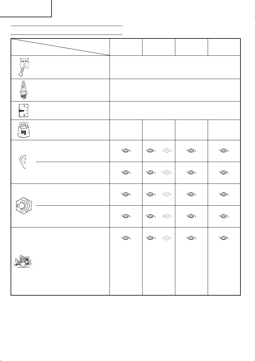
MEANINGS OF SYMBOLS
NOTE: Some units do not carry them.
Symbols
WARNING
The following show symbols used for the machine. Be sure that you understand
their meaning before use.
It is important that you read, fully
understand and observe the
following safety precautions and
warnings. Careless or improper
use of the unit may cause
serious or fatal injury.
Shows maximum shaft
speed. Do not use the cutting
attachment whose max rpm
is below the shaft rpm.
Read, understand and follow all
warnings and instructions in this
manual and on the unit.
Always wear eye, head and ear
protectors when using this unit.
Do not use metal/rigid blades
when this sign is shown on the
unit.
Keep all children, bystanders
and helpers 50 ft (15 m)
away from the unit. If anyone
approaches you, stop the
engine and cutting attachment
immediately.
Be careful of thrown objects.
Before using your machine
• Read the manual carefully.
• Check that the cutting equipment is correctly assembled and adjusted.
• Start the unit and check the carburetor adjustment. See “MAINTENANCE”.
Contents
WHAT IS WHAT ....................................................3
WARNINGS AND SAFETY INSTRUCTIONS ........ 4
WARRANTY .......................................................... 5
2
SPECIFICATIONS ................................................. 6
ASSEMBLY PROCEDURES .................................7
OPERATING PROCEDURES .............................. 11
MAINTENANCE .................................................. 14
Gloves should be worn
when necessary, e.g.,
when assembling cutting
equipment.
Use anti-slip and sturdy
footwear.
Blade thrust may occur when
the spinning blade contacts
a solid object in the critical
area. A dangerous reaction
may occur causing the entire
unit and operator to be thrust
violently. This reaction is
called blade thrust. As a result,
the operator may lose control
of the unit which may cause
serious or fatal injury. Blade
thrust is more likely to occur in
areas where it is diffi cult to see
the material to be cut.
Indicate handle location. Do
not attach handle above this
point.
Indicates blade guard
location for a trimmer head or
semi-auto cutting head.
Page 3
English
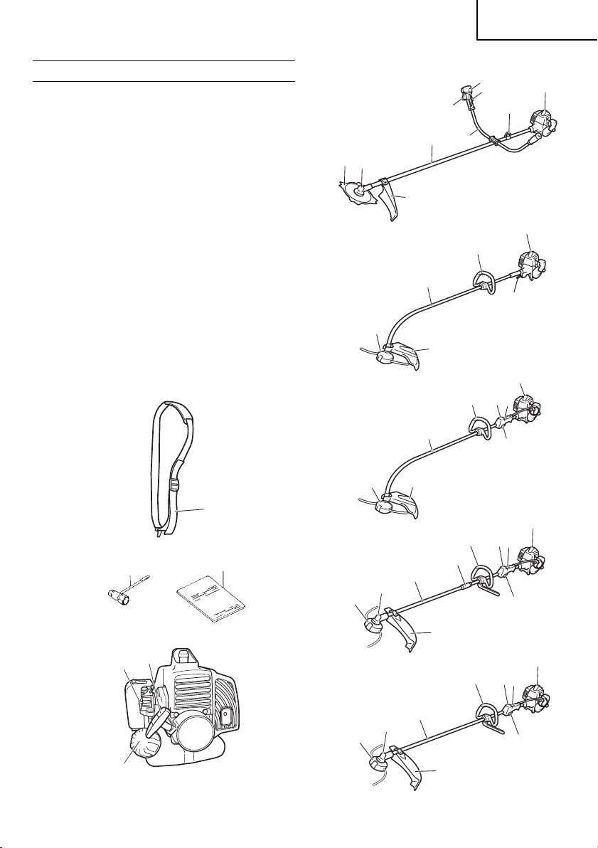
WHAT IS WHAT
Since this manual covers several models, there may
be some diff erence between pictures and your unit.
Use the instructions that apply to your unit.
1. Fuel cap
2. Throttle trigger
3. Starter handle
4. Blade guard
5. Cutting attachment
6. Drive shaft tube
7. Handle
8. Suspension eyelet
9. Ignition switch
10. Harness
11. Throttle trigger lockout
12. Choke lever
13. Engine
14. Angle transmission
15. Joint case
16. Combi box spanner
17. Handling instructions
9
11
2
7
6
5
14
4
7
6
5
4
9
7
6
5
4
13
8
13
2
13
11
2
12
10
13
9
7
11
16
3
1
17
14
5
14
5
15
6
2
4
13
7
9
11
6
2
4
3
Page 4

English
WARNINGS AND SAFETY
INSTRUCTIONS
Operator safety
○ Always wear a safety face shield or goggles.
○ Always wear heavy, long pants, boots and
gloves. Do not wear loose clothing, jewelry, short
pants, sandals or go barefoot. Secure hair so it is
above shoulder length.
○ Do not operate this tool when you are tired,
ill or under the infl uence of alcohol, drugs or
medication.
○ Never let a child or inexperienced person operate
the machine.
○ Wear hearing protection. Pay attention to your
surroundings. Be aware of any bystanders who
may be signaling a problem. Remove safety
equipment immediately upon shutting off engine.
○ Wear head protection.
○ Never start or run the engine inside a closed
room or building. Breathing exhaust fumes can
kill.
○ Keep handles free of oil and fuel.
○ Keep hands away from cutting equipment.
○ Do not grab or hold the unit by the cutting
equipment.
○ When the unit is turned off , make sure the cutting
attachment has stopped before the unit is set
down.
○ When operation is prolonged, take a break from
time to time so that you may avoid possible
Hand-Arm Vibration Syndrome (HAVS) which is
caused by vibration.
WARNING
● Antivibration systems do not guarantee that
you will not sustain Hand-Arm Vibration
Syndrome or carpal tunnel syndrome.
Therefore, continual and regular users
should monitor closely the condition of
their hands and fi ngers. If any symptoms
of the above appear, seek medical advice
immediately.
● If you are using any medical electric/
electronic devices such as a pacemaker,
consult your physician as well as the device
manufacturer prior to operating any power
equipment.
Unit/machine safety
○ Inspect the entire unit/machine before each use.
Replace damaged parts. Check for fuel leaks and
make sure all fasteners are in place and securely
tightened.
○ Replace parts that are cracked, chipped or
damaged in any way before using the unit/
machine.
○ Make sure the safety guard is properly attached.
○ Keep others away when making carburetor
adjustments.
○ Use only accessories as recommended for this
unit/machine by the manufacturer.
WARNING
Never modify the unit/machine in any way.
Do not use your unit/machine for any job
except that for which it is intended.
Fuel safety
○ Mix and pour fuel outdoors and where there are
no sparks or fl ames.
○ Use a container approved for fuel.
○ Do not smoke or allow smoking near fuel or the
unit/machine or while using the unit/machine.
○ Wipe up all fuel spills before starting engine.
○ Move at least 10 ft (3 m) away from fueling site
before starting engine.
○ Stop engine before removing fuel cap.
○ Empty the fuel tank before storing the unit/
machine. It is recommended that the fuel be
emptied after each use. If fuel is left in the tank,
store so fuel will not leak.
○ Store unit/machine and fuel in area where fuel
vapors cannot reach sparks or open fl ames
from water heaters, electric motors or switches,
furnaces. etc.
WARNING
Fuel is easy to ignite or get explosion or
inhale fumes, so that pay special attention
when handling or fi lling fuel.
Cutting safety
○ Do not cut any material other than grass and
brush.
○ Inspect the area to be cut before each use.
Remove objects which can be thrown or become
entangled.
○ For respiratory protection, wear an aerosol
protection mask when cutting the grass after
insecticide is scattered.
○ Keep others including children, animals,
bystanders and helpers outside the 50 ft (15 m)
hazard zone. Stop the engine immediately if you
are approached.
○ Always keep the engine on the right side of your
body.
○ Hold the unit/machine fi rmly with both hands.
○ Keep fi rm footing and balance. Do not over-
reach.
4
Page 5

English
○ Keep all parts of your body away from the muffl er
and cutting attachment when the engine is
running.
○ Keep cutting attachment below waist level.
○ When relocating to a new work area, be sure to
shut off the machine and ensure that all cutting
attachments are stopped.
○ Never place the machine on the ground when
running.
○ Always ensure that the engine is shut off and any
cutting attachments have completely stopped
before clearing debris or removing grass from the
cutting attachment.
○ Always carry a fi rst-aid kit when operating any
power equipment.
○ Never start or run the engine inside a closed
room or building and/or near infl ammable liquids.
Breathing exhaust fumes can kill.
Maintenance safety
○ Maintain the unit/machine according to
recommended procedures.
○ Disconnect the spark plug before performing
maintenance except for carburetor adjustments.
○ Keep others away when making carburetor
adjustments.
○ Use only genuine Hitachi replacement parts as
recommended by the manufacturer.
Transport and storage
○ Carry the unit/machine by hand with the engine
stopped and the muffl er away from your body.
○ Allow the engine to cool, empty the fuel tank,
and secure the unit/machine before storing or
transporting in a vehicle.
○ Empty the fuel tank before storing the unit/
machine. It is recommended that the fuel be
emptied after each use. If fuel is left in the tank,
store so fuel will not leak.
○ Store unit/machine out of the reach of children.
○ Clean and maintain the unit carefully and store it
in a dry place.
○ Make sure engine switch is off when transporting
or storing.
○ When transporting in a vehicle, cover blade with
blade cover.
WARNING
Indicates a strong possibility of severe
personal injury or loss of life, if instructions
are not followed.
CAUTION
Indicates a possibility of personal injury or
equipment damage, if instructions are not
followed.
NOTE
Helpful information for correct function and use.
CAUTION
Do not disassemble the recoil starter. You
may get a possibility of personal injury with
recoil spring.
WARRANTY
The warranties provided by Hitachi Koki U.S.A., Ltd.
are explained in the warranty card enclosed with this
product titled “Hitachi Outdoor Power Equipment
Limited Warranty”.
Models CG22EAB(SLP) and CG22EAB(L) are NOT
intended for commercial use, and therefore, NO
warranty is provided to their commercial applications
and rental applications. Therefore, the two year
warranty for “the fi rst commercial end user” and one
year warranty for “rental applications” mentioned in
the warranty card are provided on CG22EAS(SLP),
CG22EAS(SL), CG22EAS(S), CG22EAD(SLP) and
CG22EAD(SL), but NOT on CG22EAB(SLP) and
CG22EAB(L).
If situations occur which are not covered in this
manual, take care and use common sense. Contact
your Hitachi dealer if you need assistance. Pay
special attention to statements preceded by the
following words:
5
Page 6
English
SPECIFICATIONS
CG22EAS (SLP)
Model
Engine Size (cu. in.) 1.27 (21.1 ml)
Spark Plug Champion CJ6 or equivalent
Fuel Tank Capacity (fl . oz) 14.9 (0.44 l)
Dry Weight (Ibs) 9.7 (4.4 kg) 10.4 (4.7 kg) 10.4 (4.7 kg)
Sound pressure
level LpA (dB (A))
(EN27917)
Measured sound
power level LwA
(dB (A))
Measured sound
power level LwA
(dB (A))
Guaranteed
sound power
level LwA (dB (A))
Equivalent
(ISO10884)
Equivalent
(2000/14/EC)
Racing
(2000/14/EC)
Racing
CG22EAS (SL)
90 89 91 90 90
104 104 103 104 104
107 107 106 107 107
108 109 108 108 109
CG22EAS (S)
CG22EAD (SLP)
CG22EAD (SL)
CG22EAB (SLP)
CG22EAB (L)
8.8 (4.0 kg)
8.6 (3.9 kg)
Vibration level (m/s2)
(ISO7916)
Equivalent (Front / Left handle)
Equivalent (Rear / Right handle)
Idling (Front / Left handle)
Idling (Rear / Right handle)
Racing (Front / Left handle)
Racing (Rear / Right handle)
NOTE
Equivalent noise level/vibration level are calculated as the time-weighted energy total for noise/vibration
levels under various working conditions with the following time distribution: 1/2 Idle, 1/2 racing.
* All data subject to change without notice.
6
6.7
4.1
4.9
3.3
8.0
4.7
4.5
4.8
2.7
3.4
5.8
5.9
4.7
4.3
2.7
3.4
6.1
5.1
7.7
4.7
4.1
3.7
10.1
5.5
6.5
6.9
5.3
3.8
7.6
8.9
Page 7

English
ASSEMBLY PROCEDURES
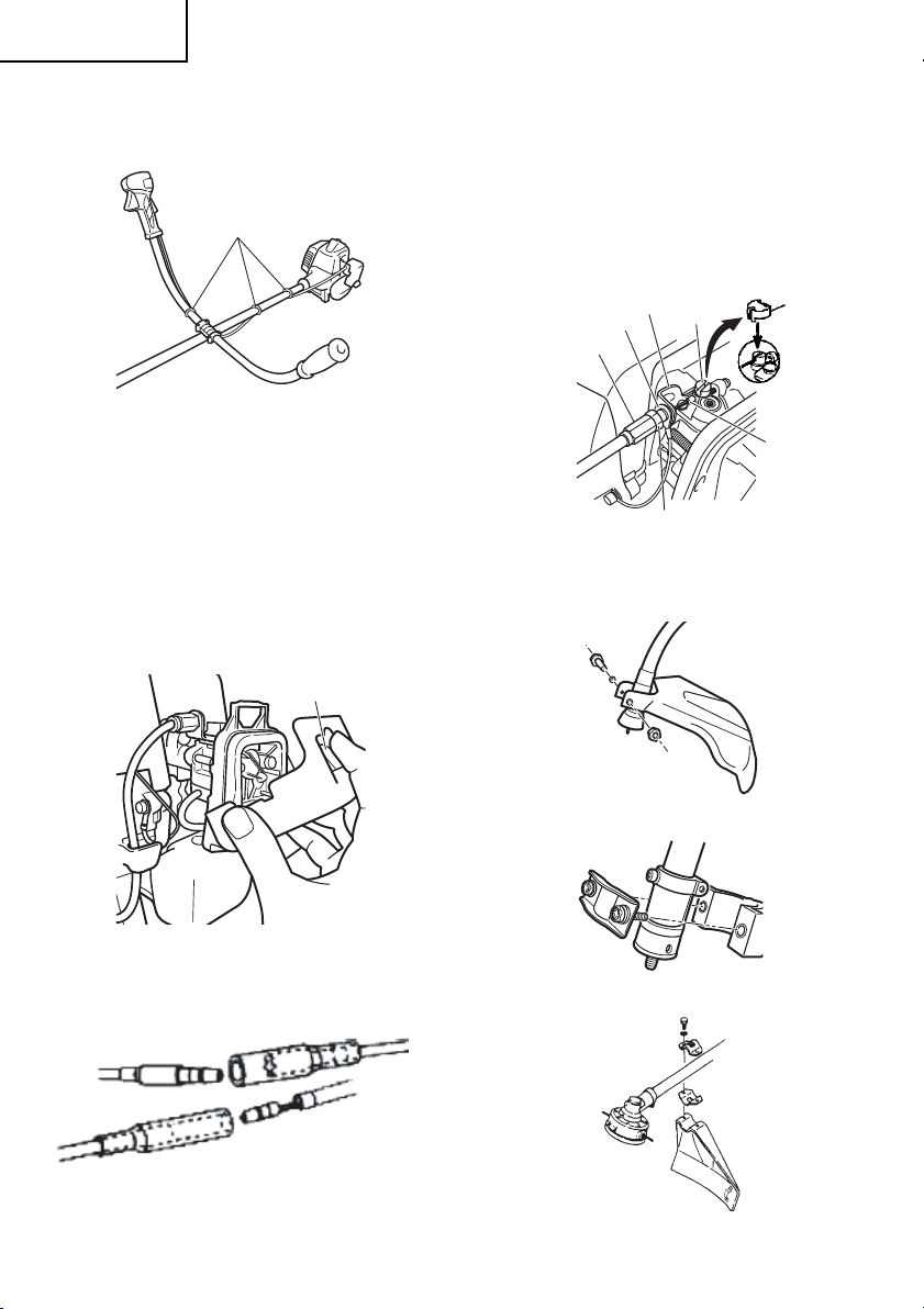
Drive shaft to engine (Fig. 1)
Loosen tube locking bolt (1) about ten turns so that
the bolt point will not obstruct drive shaft tube to be
inserted. When inserting drive shaft tube, hold the
tube locking bolt outward preventing inside fi tting
from obstructing as well.
Insert the drive shaft into the clutch case of the
engine properly until the marked position (2) on the
drive shaft tube meets the clutch case.
Some models may come with the drive shaft already
installed.
1
2
Fig. 1
NOTE
When it is hard to insert drive shaft up to the
marked position on the drive shaft tube, turn
drive shaft by the cutter mounting end clockwise
or counter-clockwise. Tighten tube locking bolt
lining up the hole in the shaft tube. Then tighten
clamp bolt securely.
Installation of attachment
1. Join the attachment in place of it.
2. Make sure the lock pin (3) fi ts in the location hole
(4) of tube and that the tube will not come off .
(Fig. 2)
3. Tighten the knob nut (5) securely. (Fig. 2)
1
2
Installation of handle
WARNING
When you use steel/rigid blades on straight
shaft trimmers or brush cutters, always use
a barrier bar (6) and shoulder harness with
the loop handle. (Fig. 3)
6
Fig. 3
Attach the handle to the drive shaft tube with the
angle towards the engine.
Adjust the location to the most comfortable position
before operation.
NOTE
If your unit has handle location label on drive
shaft tube, follow the illustration.
Remove the handle bracket (7) from the assembly.
(Fig. 4)
Place the handles and attach the handle bracket with
four bolts lightly. Adjust to appropriate position. Then
attach it fi rmly with the bolts.
7
3
5
4
Fig. 4
Fig. 2
7
Page 8
English
Attach the protection tube to the drive shaft or handle
using cord clamps (8). (Fig. 5)
8
Fig. 5
NOTE
If the protection tube is set apart from the handle
or pipe, it will be caught by something during
operation and it may cause serious injury. Do not
set the protection tube apart from the handle or
pipe.
Throttle wire / stop cord
Press the upper tab (9) and open the air cleaner
cover. (Fig. 6)
9
If the throttle outer end (10) is threaded on your unit,
screw it and the earth terminal (11) (if so equipped)
into the cable adjuster stay (12) all the way, and then
tighten this cable end using the adjuster nut (13)
against the cable adjuster stay (12).
Connect throttle wire end (14) to carburetor (15)
and install swivel cap (16) (if so equipped) where is
included in tool bag, onto swivel (15) (Fig. 8).
Some models may come with the parts installed.
12
11
10
Installation of blade guard (Fig. 9, 10, 10-1, 11)
15
13
Fig. 8
16
14
Fig. 6
Connect stop cords. (Fig. 7)
Fig. 7
8
Fig. 9
Fig. 10
Fig. 10-1
Page 9

Fig. 11
NOTE
The guard bracket may come already mounted to
the gear case on some models.
Install the blade guard on drive shaft tube against
angle transmission. Tighten the guard bracket fi rmly
so that the blade guard does not swing or move
down during operation.
English
NOTE
○ When attaching the guard extension to the blade
guard, the sharp line limiter must be removed
from the blade guard, (if so installed).
○ If your unit has guard location label on drive shaft
tube, follow the indication.
○ To remove the guard extension, refer to the
drawings. Wear gloves as the extension has a
sharp line limiter, then push the four square tabs
on the guard one by one in order. (Fig. 13)
Install the blade guard to the guard bracket, which
also secures the guard to the gear case using the
two guard mounting screws.
CAUTION
Some blade guards are equipped with sharp
line limiters. Be careful with handling it.
When using a trimmer head with two piece type
blade guard, attach the guard extension to the blade
guard. (Fig. 12)
Fig. 12
Fig. 13
Installation of semi-auto cutting head
1. Function
Automatically feeds more nylon cutting line
when it is tapped at low rpm (not greater than
4,500 rpm).
9
Page 10

English
Specifi cations
Code No.
6696454
6696597
Applicable nylon cord
2. Precautions
○ The case must be securely attached to the cover.
○ Check the cover, case and other components for
○ Check the case and button for wear.
If the wear limit mark (17) on the case is no longer
Type of
attaching
screw
Female
screw
Female
screw
Cord diameter: 1/8˝ (Φ3.0 mm) Length: 6.5 ft (2 m)
Cord diameter: 3/22˝ (Φ2.4 mm) Length: 13 ft (4 m)
cracks or other damage.
visible or there is a hole in the bottom (18) of the
button, change the new parts immediately. (Fig.
14)
17
Direction of
rotation
Counterclockwise
Clockwise
18
Size of
attaching
screw
M10×P1.25LH
M8×P1.25RH
19
Fig. 15
For curved shaft models, the mounting nut is righthand-threaded. Turn counterclockwise to loosen/
clockwise to tighten.
NOTE
○ Since the cutter holder cap is not used here, keep
it for when a metal blade is used, if so equipped.
○ Insert Allen wrench (19) into the hole of the gear
case in order to lock the cutter holder.
4. Adjusting line length
○ Set the engine speed as low as possible and tap
the head on the ground. The nylon line will be
drawn out about 1-3/16˝ (3 cm) with each tap.
(Fig. 16)
Fig. 14
○ The cutting head must be securely mounted to
the unit’s gear case.
○ For outstanding performance and reliability,
always use Hitachi nylon cutting line. Never
use wire or other materials that could become a
dangerous projectile.
○ If the cutting head does not feed cutting line
properly, check that the nylon line and all
components are properly installed. Contact your
Hitachi dealer if you need assistance.
3. Installation (Fig. 15)
○ Install cutting head on gear case of grass
trimmers/brush cutters. The mounting nut is
left-hand-threaded. Turn clockwise to loosen/
counterclockwise to tighten.
10
Fig. 16
Also, you can extend the nylon line by hand but
the engine must be completely stopped. (Fig. 17)
Fig. 17
○ Adjust the nylon line to the proper length
of 4-11/32˝–5-1/2˝ (11–14) cm before each
operation.
Page 11

English
Installation of cutting blade (Fig. 18)
(If so equipped)
When installing a cutting blade, make sure that there
are no cracks or any damage in it and that the cutting
edges are facing the correct direction.
19
21
20
22
23
Fig. 18
NOTE
○ When installing cutter holder cap (20), be sure to
set concave side upward.
○ Insert the alien wrench (19) into the hole of the
angle transmission in order to lock the cutter
holder (21). Please note that the cutter fi xing bolt
or nut (22) has left-handed threads, (clockwise to
loosen/ counter-clockwise to tighten). Tighten the
fi xing bolt or nut with the box wrench.
○ If your unit is of a nut securing type and equipped
with a cotter pin, the blade must be retained with
a new pin (23) each time installed. (Fig. 19)
23
Fig. 19
CAUTION
● Before operation, make sure the blade has
been properly installed.
● If your unit is equipped with protection cover
under a cutting blade, check it for wear or
cracks before operation. If any damage or
wear is found, replace it, as it is an article of
consumption.
WARNING
For Hitachi heads, use only fl exible,
non-metallic line recommended by the
manufacturer. Never use wire or wire ropes.
They can break off and become a dangerous
projectile.
OPERATING PROCEDURES
Fuel (Fig. 20)
Fig. 20
WARNING
● The trimmer is equipped with a two-stroke
engine. Always run the engine on fuel, which
is mixed with oil.
Provide good ventilation, when fueling or
handling fuel.
● Fuel contains highly fl ammable and it is
possible to get the serious personal injury
when inhaling or spilling on your body.
Always pay attention when handling fuel.
Always have good ventilation when handling
fuel inside building.
Fuel
○ Always use branded 89 octane unleaded
gasoline.
○ Use genuine two-cycle oil or use a mix between
25:1 to 50:1, please consult the oil bottle for the
ratio or Hitachi dealer.
○ If genuine oil is not available, use an anti-oxidant
added quality oil expressly labeled for air-cooled
2-cycle engine use (JASO FC GRADE OIL or ISO
EGC GRADE). Do not use BIA or TCW (2-stroke
water-cooling type) mixed oil.
○ Never use multi-grade oil (10 W/30) or waste oil.
○ Always mix fuel and oil in a separate clean
container.
Always start by fi ling half the amount of fuel, which
is to be used. Then add the whole amount of oil. Mix
(shake) the fuel mixture. Add the remaining amount
of fuel.
Mix (shake) the fuel-mix thoroughly before fi lling the
fuel tank.
11
Page 12
English
Fueling
WARNING
● Always shut off the engine before refueling.
● Slowly open the fuel tank, when fi lling up
with fuel, so that possible over-pressure
disappears.
● Tighten the fuel cap carefully, after fueling.
● Always move the trimmer at least 10 ft (3 m)
from the fueling area before starting.
● Always wash any spilled fuel from clothing
immediately with soap.
● Be sure to check for any fuel leakage after
refueling.
Before fueling, clean the tank cap area carefully,
to ensure that no dirt falls into the tank. Make sure
that the fuel is well mixed by shaking the container,
before fueling.
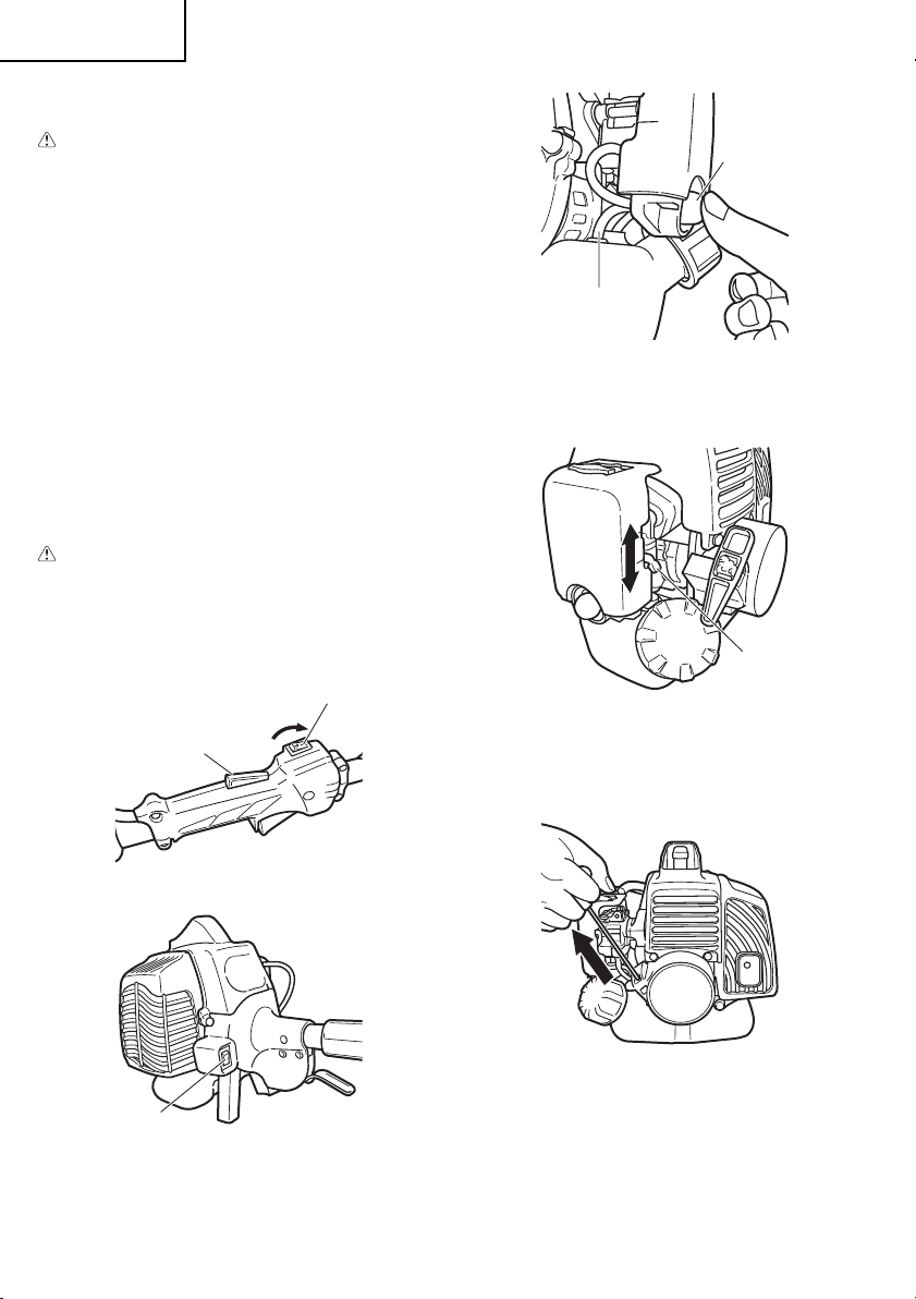
Starting
CAUTION
Before starting, make sure the cutting
attachment does not touch anything.
1. Set ignition switch (24) to ON position. (Fig. 21,
22)
24
26
25
39
Fig. 23
2. Set choke lever (27) to CLOSED position (A).
(Fig. 24)
B
A
27
Fig. 24
3. Pull recoil starter briskly, taking care to keep the
handle in your grasp and not allowing it to snap
back. (Fig. 25)
Fig. 21
24
Fig. 22
* Push priming bulb (25) several times so that fuel
fl ows through return pipe (39). (Fig. 23)
12
Fig. 25
Page 13

4. When you hear the engine want to start, return
choke lever to RUN position (open) (B). Then pull
recoil starter briskly again.
NOTE
If engine does not start, repeat procedures from
2 to 5.
5. Then allow the engine about 2–3 minutes to warm
up before subjecting it to any load.
English
Cutting (Fig. 26, 27, 28)
○ When cutting, operate engine at over 6,500 rpm.
Extended time of use at low rpm may wear out
the clutch prematurely.
○ Cut grass from right to left.
○ Cut grass from left to right (only curve shaft
model).
○ Blade thrust may occur when the spinning blade
contacts a solid object in the critical area.
A dangerous reaction may occur causing the
entire unit and operator to be thrust violently. This
reaction is called blade thrust. As a result, the
operator may lose control of the unit which may
cause serious or fatal injury. Blade thrust is more
likely to occur in areas where it is diffi cult to see
the material to be cut.
○ Wear the harness as shown in the fi gure (if so
equipped). The blade turns counter-clockwise,
therefore, be advised to operate the unit from
right to left for effi cient cutting. Keep onlookers
out of working area at least 50 ft (15 m).
Fig. 27
50 ft
(15 m)
Fig. 28
WARNING
If cutting attachment should strike against
stones or other debris, stop the engine and
make sure that the attachment and related
parts are undamaged. When grass or vines
wrap around attachment, stop engine and
attachment and remove them.
Stopping (Fig. 29, 30)
Decrease engine speed and run at an idle for a few
minutes, then turn off ignition switch (24).
24
26
Fig. 26
Fig. 29
13
Page 14

English
Carburetor adjustment (Fig. 31)
24
Fig. 30
For models with an engine ignition switch, keep the
ignition switch pressed until the engine comes to a
complete stop.
WARNING
A cutting attachment can injure while it
continues to spin after the engine is stopped
or power control is released. When the unit is
turned off , make sure the cutting attachment
has stopped before the unit is set down.
Semi-auto cutting head
○ When cutting, operate engine at over 6,500 rpm.
Extended time of use at low rpm may wear out
the clutch prematurely.
○ Cut grass from right to left.
○ Cut grass from left to right (only curve shaft
model).
WARNING
A cutting attachment can injure while it
continues to spin after the engine is stopped
or power control is released. When the unit is
turned off , make sure the cutting attachment
has stopped before the unit is set down.
Automatically feeds more nylon cutting line when it is
tapped at low rpm (not greater than 4,500 rpm).
MAINTENANCE
MAINTENANCE, REPLACEMENT OR REPAIR
OF THE EMISSION CONTROL DEVICES AND
SYSTEMS MAY BE PERFORMED BY ANY NONROAD ENGINE REPAIR ESTABLISHMENT OR
INDIVIDUAL.
Fig. 31
WARNING
● The cutting attachment may be spinning
during carburetor adjustments.
● Never start the engine without the complete
clutch cover and tube assembled! Otherwise
the clutch can come loose and cause
personal injuries.
In the carburetor, fuel is mixed with air. When the
engine is test run at the factory, the carburetor is
basically adjusted. A further adjustment may be
required, according to climate and altitude. The
carburetor has one adjustment possibility:
T = Idle speed adjustment screw.
Idle speed adjustment (T)
Check that the air fi lter is clean. When the idle
speed is correct, the cutting attachment will not
rotate. If adjustment is required, close (clockwise)
the T-screw, with the engine running, until the
cutting attachment starts to rotate. Open (counterclockwise) the screw until the cutting attachment
stops. You have reached the correct idle speed
when the engine runs smoothly in all positions well
below the rpm when the cutting attachment starts to
rotate.
If the cutting attachment still rotates after idle speed
adjustment, contact your Hitachi dealer.
NOTE
Standard Idle rpm is 2,800 – 3,200 rpm.
WARNING
When the engine is idling the cutting
attachment must under no circumstances
rotate.
14
Page 15

English
Air fi lter (Fig. 32)
The air fi lter must be cleaned from dust and dirt in
order to avoid:
○ Carburetor malfunctions
○ Starting problems
○ Engine power reduction
○ Unnecessary wear on the engine parts
○ Abnormal fuel consumption
Clean the air fi lter daily or more often if working in
exceptionally dusty areas.
28
Fig. 32
Cleaning the air fi lter
Open the air fi lter cover and the fi lter (28). Rinse it in
warm soap suds. Check that the fi lter is dry before
reassembly. An air fi lter that has been used for some
time cannot be cleaned completely. Therefore,
it must regularly be replaced with a new one. A
damaged fi lter must always be replaced.
Fuel fi lter (Fig. 33)
Drain all fuel from fuel tank and pull fuel fi lter line
from tank. Pull fi lter element out of holder assembly
and rinse element in warm water with detergent.
Rinse thoroughly until all traces of detergent are
eliminated. Squeeze, do not wring, away excess
water and allow element to air dry.
NOTE
If element is hard due to excessive dirt buildup,
replace it.
Spark plug (Fig. 34)
The spark plug condition is infl uenced by:
○ An incorrect carburetor setting
○ Wrong fuel mixture (too much oil in the gasoline)
○ A dirty air fi lter
○ Hard running conditions (such as cold weather)
These factors cause deposits on the spark plug
electrodes, which may result in malfunction and
starting diffi culties. If the engine is low on power,
diffi cult to start or runs poorly at idling speed, always
check the spark plug fi rst. If the spark plug is dirty,
clean it and check the electrode gap. Re-adjust
if necessary. The correct gap is 0.024˝ (0.6 mm).
The spark plug should be replaced after about 100
operation hours or earlier if the electrodes are badly
eroded.
0.024˝
(0.6 mm)
Fig. 34
NOTE
In some areas, local law requires using a resistor
spark plug to suppress ignition signals. If this
machine was originally equipped with resistor
spark plug, use same type of spark plug for
replacement.
Flexible drive shaft (Fig. 35)
Flexible drive shaft should be removed and
lubricated with good quality lithium grease every
20 hours. To remove the fl exible shaft, fi rst remove
screw (29), loosen bolt (30) and remove the gear
case then pull the shaft out of the drive shaft pipe.
Clean the shaft off and apply a generous coat of
lithium grease to it and insert if back into the drive
shaft pipe, turn it unit it drops into place then install
the gear case, install & tighten screw (29) and screw
(30).
Fig. 33
15
Page 16

English
Wind both halves of the line on the reel in the
same direction, keeping each half of the line on
its own side of the partition. (Fig. 38)
30
29
Fig. 35
Angle transmission (Fig. 36)
Check angle transmission or angle gear for
grease level about every 50 hours of operation by
removing the grease fi ller plug on the side of angle
transmission.
If no grease can be seen on the fl anks of the gears,
fi ll the transmission with quality lithium based
multipurpose grease up to 3/4. Do not completely fi ll
the transmission.
Fig. 36
Semi-auto cutting head
4˝ (10 cm)
32
Fig. 38
(4) Push each line into the stopper holes (33),
leaving the loose ends approx. 4˝ (10 cm) in
length. (Fig. 39)
4˝ (10 cm)
33
4˝ (10 cm)
Fig. 39
(5) Insert both loose ends of the line through the cord
guide (34) when placing the reel in the case. (Fig.
40)
33
Nylon line replacement
(1) Remove the case (31) by fi rmly pushing inward
the locking tabs with your thumbs as shown in
Fig. 37.
31
Fig. 37
(2) After removing the case, take out the reel and
discard the remaining line.
(3) Fold the new nylon line unevenly in half as shown
in picture.
Hook the U-shaped end of the nylon line into the
groove (32) on the center partition of the reel.
16
34
Fig. 40
NOTE
When placing a reel in the case, try to line up the
stopper holes (33) with the cord guide (34) for
easier line release later.
Page 17

English
(6) Place the cover over the case so that the cap
locking tabs (35) on the case meet the long holes
(36) on the cover. Then push the case securely
until it clicks into place. (Fig. 41)
36
35
Fig. 41
(7) The initial cutting line length should be approx.
4-11/32˝–5-1/2˝ (11–14 cm) and should be equal
on both sides. (Fig. 42)
4-11/32˝–5-1/2˝
(11-14 cm)
Fig. 42
4-11/32˝–5-1/2˝
(11-14 cm)
○ When replacing blade, purchase one
recommended by Hitachi, with a 25.4 mm (one
inch) fi tting hole.
○ When installing a saw blade (38), always face
the stamped side up. In the case of a 3 or 4 tooth
blade (37), it can be used on either side.
○ Use the correct blade for the type of work.
○ When replacing blades, use appropriate tools.
○ When cutting edges become dull, re-sharpen
or fi le as shown in the illustration. Incorrect
sharpening may cause excessive vibration.
○ Discard blades that are bent, warped, cracked,
broken or damaged in any way.
NOTE
When sharpening blade it is important to maintain
an original shape of radius at the base of the
tooth to avoid cracking.
Maintenance schedule
Below you will fi nd some general maintenance
instructions. For further information please contact
your Hitachi dealer.
Daily maintenance
○ Clean the exterior of the unit.
○ Check that the harness is undamaged.
○ Check the blade guard for damage or cracks.
Change the guard in case of impacts or cracks.
○ Check that the cutting attachment is properly
centred, sharp, and without cracks. An off -centre
cutting attachment induces heavy vibrations that
may damage the unit.
○ Check that the cutting attachment nut is
suffi ciently tightened.
○ Make sure that the blade transport guard is
undamaged and that it can be securely fi tted.
○ Check that nuts and screws are suffi ciently
tightened.
Blade (Fig. 43)
WARNING
Wear protective gloves when handling or
performing maintenance on the blade.
37
○ Use a sharp blade. A dull blade is more likely to
snag and thrust. Replace the fastening nut if it is
damaged and hard to tighten.
38
Fig. 43
Weekly maintenance
○ Check the starter, especially the cord and return
spring.
○ Clean the exterior of the spark plug.
○ Remove it and check the electrode gap. Adjust it
to 0.024˝ (0.6 mm), or change the spark plug.
○ Check that the angle gear is fi lled with grease up
to 3/4.
○ Clean the air fi lter.
Monthly maintenance
○ Rinse the fuel tank with gasoline.
○ Clean the exterior of the carburetor and the space
around it.
○ Clean the fan and the space around it.
17
Page 18

Français
SIGNIFICATION DES SYMBOLES
REMARQUE:
Certains appareils n’en sont pas pourvus.
Symboles
ATTENTION
Les symboles suivants sont utilisés pour l’outil. Bien se familiariser avec leur
signifi cation avant d’utiliser l’outil.
Il est essentiel de lire et de comprendre
parfaitement les consignes de sécurité
et autres avertissements suivants.
Vous devez les observer strictement.
L’utilisation inattentive ou inadéquate
de cette machine risque de provoquer
des blessures graves ou fatales.
Indique la vitesse maximale de l’arbre.
N’utilisez pas d’outil de coupe dont la
vitesse de rotation (nombre de tours/
minute) est inférieure à la vitesse
de rotation de l’arbre.
Lisez attentivement et respectez toutes les
instructions et tous les avertissements donnés
dans ce manuel et sur le produit.
Utilisez toujours des lunettes de protection
ainsi qu’un casque et des protections
d’oreilles lorsque vous utilisez ce
produit.
N’utilisez pas de lames métalliques/
rigides lorsque ce signe apparaît sur
la machine.
Maintenez les enfants, spectateurs
et aides à plus de 50 pieds (15 m) de
l’appareil. Si quelqu’un s’approche de
vous, coupez immédiatemment le moteur
et arrêtez l’outil de coupe.
Faites attention aux projections
d’objets.
Avant l’utilisation de votre nouvelle machine
• Lisez attentivement le manuel d’utilisation.
• Vérifi ez que l’équipement de coupe est monté et réglé correctement.
• Démarrez la machine et vérifi ez le réglage du carburateur. Voir la section “ENTRETIEN”.
Sommaire
DESCRIPTION ..................................................... 19
PRÉCAUTIONS ET CONSIGNES DE SÉCURITÉ
GARANTIE ........................................................... 21
18
CARACTÉRISTIQUES ......................................... 22
... 20
MONTAGE ........................................................... 23
UTILISATION ........................................................ 27
ENTRETIEN ......................................................... 30
Au besoin, utilisez des gants,
notamment lors du montage de
l’équipement de coupe.
Utilisez des chaussures antidérapantes
et solides.
Une réaction de poussée de la lame peut
survenir lorsque la lame en rotation entre
en contact avec un objet solide dans la
zone critique. Une réaction dangereuse
peut alors survenir, provoquant un
mouvement incontrôlé et violent de
toute la machine et de l’utilisateur.
Cette réaction est appelée rebond.
Elle peut faire perdre le contrôle de la
machine et être à l’origine de blessures
sérieuses, voire fatales. Cette réaction
incontrôlée de la lame risque davantage
de survenir lorsque l’opérateur ne peut
voir le matériau à couper.
Indique l’emplacement de la poignée.
Ne positionnez pas la poignée audessus de ce point.
Indique l’emplacement du protègelame pour un coupe-herbe ou une tête
de coupe semi-automatique.
Page 19

Français
DESCRIPTION
Ce manuel étant commun à plusieurs modèles, vous
constaterez peut-être certaines diff érences entre
les images et votre appareil. Suivez les instructions
relatives à votre modèle.
1. Bouchon du réservoir de carburant
2. Commande des gaz
3. Poignée du lanceur
4. Protège-lame
5. Outil de coupe
6. Tube de transmission
7. Poignée
8. Œillet d’accrochage
9. Interrupteur marche-arrêt
10. Harnais
11. Levier accélérateur bloqué
12. Levier d’étranglement
13. Moteur
14. Boîtier de renvoi d’angle
15. Boîtier de raccordement
16. Clé à douille multiple
17. Mode d’emploi
9
11
2
7
6
5
14
4
7
6
5
4
9
7
6
5
4
13
8
13
2
13
11
2
12
10
13
9
7
11
16
3
1
17
14
5
14
5
15
6
2
4
13
7
9
11
6
2
4
19
Page 20

Français
PRÉCAUTIONS ET CONSIGNES
DE SÉCURITÉ
Sécurité de l’utilisateur
○ Portez toujours une visière et des lunettes de
protection.
○ Portez toujours un pantalon, des chaussures
et des gants de sécurité. Évitez les vêtements
amples, les shorts, les sandales et les pieds nus.
Veillez à ce que vos cheveux ne descendent pas
au-dessous des épaules.
○ Utilisez cette machine uniquement si vous êtes
en pleine possession de vos moyens physiques.
Évitez strictement la consommation d’alcool, de
drogue ou de médicaments.
○ Ne laissez jamais un enfant ou une personne
inexpérimentée se servir de ces machines.
○ Portez un dispositif de protection auditive
contre le bruit. Restez vigilant à tout ce qui vous
entoure. Restez attentif dans l’éventualité où une
personne située à proximité vous signalerait un
problème. Retirez les équipements de sécurité
immédiatement après avoir coupé le moteur de
l’appareil.
○ Protégez-vous la tête.
○ Ne mettez jamais le moteur en marche dans un
local clos, les gaz d’échappement étant toxiques.
○ Nettoyez les poignées de toute trace d’huile ou de
carburant.
○ N’approchez jamais les mains du guide-chaîne et
de la chaîne.
○ N’attrapez jamais et ne tenez jamais la machine
par l’extrémité du guide-chaîne.
○ Après l’arrêt de la machine, attendez l’arrêt
complet de l’outil de coupe avant de poser la
machine.
○ Lors d’une utilisation prolongée, veillez à pratiquer
des pauses régulières afi n d’éviter des troubles
éventuels provoqués par les vibrations.
ATTENTION
● Les systèmes anti-vibrations ne préviennent
pas de la maladie des doigts blancs, ni du
syndrome du canal carpien. Par conséquent,
en cas d’utilisation régulière et continue de
votre machine, surveillez soigneusement
l’état de vos mains et de vos doigts. Si l’un
des symptômes ci-dessus venait à apparaître,
il serait indispensable de vous faire examiner
immédiatement par votre médecin.
● Si vous êtes équipé d’un appareillage médical
électrique/électronique tel qu’un stimulateur
cardiaque, consultez votre médecin et le
fabricant de cet appareillage avant d’utiliser
tout appareil électrique.
Règles de sécurité concernant l’utilisation de la
machine.
○ Contrôlez entièrement votre machine avant
chaque utilisation. Remplacez les pièces
endommagées. Vérifi ez l’absence de fuites de
carburant et assurez-vous que tous les dispositifs
de fi xation sont en place et solidement fi xés.
○ Remplacez les éléments Hitachi de la machine
qui présentent des fi ssures, des ébréchures ou
toute autre avarie.
○ Vérifi ez que les systèmes de sécurité sont
fonctionnels.
○ Ne laissez personne s’approcher lorsque vous
réglez le carburateur.
○ Utilisez uniquement les accessoires recommandés
par le constructeur pour cette machine.
ATTENTION
Ne modifi ez en aucun cas la machine.
N’utilisez jamais la débroussailleuse pour
un autre usage que celui pour lequel elle est
prévue.
Sécurité au niveau du carburant
○ Faites le mélange et le plein à l’air libre, à distance
de toute étincelle ou fl amme.
○ Utilisez un récipient agréé pour l’essence.
○ Ne fumez pas et ne laissez personne fumer
à proximité du carburant ou de la machine, ni
lorsque vous utilisez la machine.
○ Essuyez soigneusement toutes les traces de
carburant avant de mettre le moteur en marche.
○ Pour démarrer la débroussailleuse, écartez-vous
d’au moins 10 pieds (3 mètres) de l’endroit où
vous avez fait le plein.
○ Arrêtez le moteur avant de dévisser les bouchons
des réservoirs de carburant ou d’huile.
○ Vidangez le réservoir de carburant avant de ranger
la machine. Cette opération est recommandée
après chaque utilisation. Si le réservoir n’est pas
vide, rangez alors la machine dans une position
empêchant toute fuite de carburant.
○ Rangez la machine et le carburant dans un endroit
où les vapeurs d’essence ne risquent pas d’entrer
en contact avec des étincelles ou une fl amme
en provenance d’un chauff e-eau, d’un moteur
électrique, d’un commutateur, d’une chaudière,
etc.
ATTENTION
Le carburant peut s’enfl ammer facilement ou
exploser et l’inhalation de ses vapeurs est
dangereuse. Faites particulièrement attention
lorsque vous manipulez le carburant ou faites
l’appoint du réservoir.
20
Page 21

Français
Sécurité au niveau de la coupe
○ Ne coupez rien d’autre que de l’herbe et des
broussailles.
○ Examinez la zone de coupe avant chaque
utilisation. Enlevez tout objet pouvant être projeté
ou s’emmêler dans la machine.
○ Pour la protection des voies respiratoires, portez
un masque de protection contre les aérosols lors
de la coupe d’une végétation traitée avec des
insecticides.
○ Veillez à ce que personne (enfants, animaux,
spectateurs ou aides) ne se tienne à l’intérieur d’un
périmètre de sécurité de 50 pieds (15 mètres).
Arrêtez immédiatement le moteur si quelqu’un
s’approche de vous.
○ Tenez toujours le moteur à votre droite.
○ Maintenez fermement la machine des deux
mains.
○ Tenez-vous bien en équilibre sur les deux jambes.
Ne travaillez jamais en porte-à-faux.
○ Restez toujours éloigné du silencieux
d’échappement et de l’ensemble de coupe
lorsque le moteur est en marche.
○ Maintenez l’outil de coupe en-dessous de la
taille.
○ Quand vous déplacez l’appareil d’un lieu à un
autre, vérifi ez qu’il est complètement arrêté et que
tous les accessoires de coupe sont à l’arrêt.
○ Ne posez jamais l’appareil sur le sol lorsque le
moteur tourne.
○ Assurez-vous toujours que le moteur est
arrêté et que tous les accessoires de coupe
sont complètement à l’arrêt avant de nettoyer
l’accessoire principal de coupe de tout débris ou
amas d’herbe.
○ Lors de l’utilisation de n’importe quel appareil
électrique/thermique, emportez toujours avec
vous une trousse de premiers soins.
○ Ne démarrez jamais le moteur de l’appareil, et ne
l’utilisez jamais dans un local clos et/ou à proximité
de produits infl ammables, les gaz d’échappement
étant toxiques.
Sécurité au niveau de l’entretien
○ Entretenez votre machine selon les
recommandations du constructeur.
○ Débranchez la bougie avant toute intervention
d’entretien, à l’exception des opérations de
réglages du carburateur.
○ Ne laissez personne s’approcher lorsque vous
réglez le carburateur.
○ Utilisez uniquement les pièces de rechange
d’origine Hitachi.
Transport et rangement
○ Portez la machine avec moteur arrêté et silencieux
orienté vers l’extérieur.
○
Laissez le moteur refroidir, videz le réservoir de
carburant et veillez à la stabilité de la machine lors du
rangement ou du chargement à bord d’un véhicule.
○ Vidangez le réservoir de carburant avant de ranger
la machine. Cette opération est recommandée
après chaque utilisation. Si le réservoir n’est pas
vide, rangez alors la machine dans une position
empêchant toute fuite de carburant.
○ Rangez la machine hors de portée des enfants.
○ Nettoyez soigneusement la machine avant de
l’entreposer dans un endroit sec.
○ Assurez-vous que le commutateur d’arrêt du
moteur est bien sur la position « stop » lors du
transport ou du rangement de la machine.
○ Lors du transport en véhicule, recouvrez la lame
avec le couvre-lame.
Dans l’éventualité de situations qui ne seraient pas
prises en compte par le présent manuel, redoublez
d’attention et usez de bon sens. Contactez un
concessionnaire Hitachi pour toute assistance. Faites
particulièrement attention aux stipulations introduites
par les mots ci-dessous.
ATTENTION
Information de première importance pour éviter
des dommages corporels graves ou mortels.
IMPORTANT
Information importante afi n d’éviter des
dommages corporels ou matériels.
REMARQUE
Information utile pour une utilisation et un
fonctionnement corrects de la machine.
IMPORTANT
Ne démontez pas le lanceur à retour
automatique. Vous pourriez vous blesser à
cause du ressort de recul.
GARANTIE
Les garanties fournies par Hitachi Koki U.S.A., Ltd.
sont indiquées sur le bon de garantie accompagnant
ce produit intitulé “Garantie limitée applicable aux
appareils électriques extérieurs Hitachi”.
Les modèles CG22EAB(SLP) et CG22EAB(L)
NE sont PAS destinés à un usage commercial,
par conséquent, AUCUNE garantie n’est fournie
concernant toute utilisation commerciale ou locative.
Ainsi, la garantie de deux ans accordée au “premier
utilisateur fi nal du produit à des fi ns commerciales”
et la garantie d’un an concernant la “location”,
mentionnées sur le bon de garantie, s’appliquent
aux modèles CG22EAS(SLP), CG22EAS(SL),
CG22EAS(S), CG22EAD(SLP) et CG22EAD(SL),
mais PAS aux modèles CG22EAB(SLP) et
CG22EAB(L).
21
Page 22

Français
CARACTÉRISTIQUES
Modèle
Taille du moteur
(cu. in.)
Bougie d’allumage Champion CJ6 ou équivalent
Contenance du réservoir de
carburant (fl . oz)
Poids à sec (livre) 9.7 (4.4 kg) 10.4 (4.7 kg) 10.4 (4.7 kg)
Niveau de pression
acoustique
LpA (dB (A)) (EN27917)
Niveau de puissance
acoustique mesuré
LwA (dB (A))
Niveau de puissance
acoustique mesuré
LwA (dB (A))
Niveau de puissance
acoustique garanti
LwA (dB (A))
Équivalent
(ISO10884)
Équivalent
(2000/14/CE)
Vitesse de
course
(2000/14/CE)
Vitesse de
course
CG22EAS (SLP)
CG22EAS (SL)
90 89 91 90 90
104 104 103 104 104
107 107 106 107 107
108 109 108 108 109
CG22EAS (S)
CG22EAD (SLP)
CG22EAD (SL)
1.27 (21.1 ml)
14.9 (0.44 l)
CG22EAB (SLP)
CG22EAB (L)
8.8 (4.0 kg)
8.6 (3.9 kg)
Niveau de vibrations (m/s2)
(ISO7916)
Équivalent (Poignée avant / gauche)
Équivalent (Poignée avant / droite)
Ralenti (Poignée avant / gauche)
Ralenti (Poignée avant / droite)
Vitesse de course
(Poignée avant / gauche)
Vitesse de course
(Poignée avant / droite)
REMARQUE
Les niveaux de bruit/vibrations équivalents sont calculés comme total d’énergie pondérée en fonction du
temps pour les niveaux de bruit/vibrations dans diverses conditions de travail avec la répartition temporelle
suivante : 1/2 ralenti, 1/2 vitesse de course.
* Toutes les données sont susceptibles d’être modifi ées sans préavis.
22
6.7
4.1
4.9
3.3
8.0
4.7
4.5
4.8
2.7
3.4
5.8
5.9
4.7
4.3
2.7
3.4
6.1
5.1
7.7
4.7
4.1
3.7
10.1
5.5
6.5
6.9
5.3
3.8
7.6
8.9
Page 23

Français
MONTAGE
Arbre d’entraînement du moteur (Fig. 1)
Desserrez la vis de blocage du tube (1) de dix tours
environ pour que la pointe de la vis n’entrave pas
le tube de protection de l’arbre de transmission à
insérer. Lors de l’insertion du tube, maintenez la
vis de blocage de ce dernier vers l’extérieur pour
empêcher que la garniture intérieure ne devienne un
obstacle.
Insérez correctement l’arbre de transmission dans
le carter d’embrayage du moteur jusqu’à ce que
la position marquée (2) sur le tube de l’arbre de
transmission touche le carter d’embrayage.
Sur certains modèles, l’arbre de transmission peut
être déjà installé.
1
2
Fig. 1
REMARQUE
Lorsque l’insertion de l’arbre de transmission
jusqu’à la position marquée sur le tube est
diffi cile, faites tourner l’arbre de transmission
autour de l’embout d’entraînement de l’outil de
coupe dans le sens des aiguilles d’une montre ou
inversement. Resserez la vis de blocage du tube
tout en alignant l’orifi ce sur le tube de l’arbre de
transmission. Ensuite, resserez fermement la vis
de blocage.
1
2
Montage de la poignée
ATTENTION
Utilisez toujours une barre de protection (6)
et un harnais de sécurité avec la poignée
lors de l’utilisation de lames en acier/rigides
montées sur un coupe-herbes ou une
débroussailleuse à arbre droit. (Fig. 3)
6
Fig. 3
Fixez la poignée au tube de transmission orientée
vers le moteur.
Choisissez la position la plus pratique avant la mise
en marche.
REMARQUE
Si le tube de l’arbre moteur comporte une étiquette
indiquant la position de la poignée, suivez les
indications fournies.
Démontez le support de poignée (7). (Fig. 4)
Ajustez les poignées puis serrez légèrement le
support de poignée à l’aide des quatre vis. Réglez
selon la position appropriée. Fixez ensuite fermement
au moyen des vis.
Montage de l’accessoire de coupe
1. Mettez le nouvel accessoire à la place du
précédent.
2. Assurez-vous que la cheville de blocage (3)
pénètre bien dans l’orifi ce de blocage (4) du tube
et que le tube ne se détache pas. (Fig. 2)
3. Serrez fermement l’écrou de blocage (5). (Fig. 2)
3
5
4
Fig. 2
7
Fig. 4
Fixez le tube de protection au tube de transmission
ou à la poignée à l’aide des colliers de cordon (8).
(Fig. 5)
23
Page 24

Français
8
Fig. 5
REMARQUE
Le tube de protection, s’il est détaché de la
poignée ou du tuyau, risque de rester accroché
pendant l’utilisation et entraîner des blessures
graves. Ne séparez pas le tube de protection de
la poignée ou du tuyau.
Câble de commande des gaz / câble de marchearrêt
Appuyez sur l’onglet supérieur (9) et ouvrez le
couvercle du fi ltre à air. (Fig. 6)
9
Si, sur votre appareil, l’extrémité externe du papillon
des gaz (10) est fi letée et que la prise de terre (11) (si
l’appareil en est équipé) est introduite à fond dans le
support d’ajustage de câble (12), serrez l’extrémité
de ce câble à l’aide de l’écrou d’ajustage (13) au
support d’ajustage de câble (12).
Connectez l’extrémité du câble de commande des
gaz (14) au carburateur (15) et installez le chapeau
tournant (16) (le cas échéant) qui se trouve dans la
trousse à outils sur le pivot (15) (Fig. 8)
Sur certains modèles, certaines parties peuvent être
déjà installées.
12
11
10
Montage du protège-lame (Fig. 9, 10, 10-1, 11)
15
13
Fig. 8
16
14
Fig. 6
Reliez les câbles de marche-arrêt. (Fig. 7)
Fig. 7
24
Fig. 9
Fig. 10
Fig. 10-1
Page 25

Fig. 11
REMARQUE
Sur certains modèles, le crochet de garde peut
déjà être installé sur le boîtier d’engrenages.
Installez le protège-lame sur le tube de l’arbre
de transmission contre le renvoi d’angle. Serrez
fermement le crochet de garde afi n que le protège-
lame ne puisse pas osciller ou bouger pendant
l’utilisation de la machine.
Français
REMARQUE
○ Lorsque vous attachez l’extension de protection
au protège-lame, le limiteur aiguisé doit être
enlevé du protège-lame (le cas échéant).
○ Si le tube de l’arbre moteur comporte une étiquette
indiquant la position de la protection, suivez les
indications fournies.
○ Pour enlever l’extension de protection, référez-
vous aux illustrations. Portez des gants, l’extension
possédant un limiteur aiguisé, puis poussez les
quatre attaches carrées sur le protège-lame l’une
après l’autre dans l’ordre. (Fig. 13)
Montez le protège-lame sur le crochet de garde, qui
stabilise également la protection au niveau du boîtier
d’engrenage à l’aide des deux vis de garde.
IMPORTANT
Certains protège-lames sont équipés d’un
limiteur aiguisé. Prenez garde lorsque vous
le maniez.
Lors de l’utilisation d’un coupe-herbes avec un
protège-lame en deux parties, attachez l’extension
de protection au protège-lame. (Fig. 12)
Fig. 12
Fig. 13
25
Page 26

Français
Montage de la tête de coupe semi-automatique
1. Fonction
Fait avancer automatiquement le fi l de coupe en
nylon lorsqu’elle est tapotée à bas régime (au plus
4,500 tr/min).
Caractéristiques
N° de
code
6696454 Vis creuse
6696597 Vis creuse
Cordon de nylon applicable
Diamètre du cordon :
Diamètre du cordon :
2. Précautions
○ Le boîtier doit être attaché solidement au
○ Vérifi ez s’il y a des fi ssures ou d’autres
○ Vérifi ez si le boîtier et le bouton sont usés.
Si la marque de limite d’usure (17) sur le boîtier
Type de
vis de
fi xation
couvercle.
dommages sur le couvercle, le boîtier et les autres
composants.
n’est plus visible ou qu’il y a un trou au bas (18)
du bouton, changez immédiatement les nouvelles
pièces. (Fig. 14)
17
Sens de la
rotation
Sens
antihoraire
Dans le sens
des aiguilles
d’une montre
1/8˝ (Φ3.0 mm)
Longueur
3/22˝ (Φ2.4 mm)
Longueur :
: 6.5 pieds (2 m)
13 pieds (4 m)
18
Taille de vis
de fi xation
M10×P1.25LH
M8×P1.25RH
d’autres matériaux qui pourraient constituer de
dangereux projectiles.
○ Si le fi l de coupe n’avance pas bien dans la tête de
coupe, vérifi ez si le fi l nylon et tous les composants
sont bien installés. Contactez un concessionnaire
Hitachi pour toute assistance.
3. Installation (Fig. 15)
○ Installez la tête de coupe sur le boîtier
d’engrenages du coupe-herbes ou de la
débroussailleuse. L’écrou de montage est muni
d’un fi let à gauche. Tournez dans le sens des
aiguilles d’une montre pour desserrer et dans le
sens inverse pour serrer.
19
Fig. 15
Pour les modèles à arbre courbe, l’écrou de montage
est muni d’un fi letage à droite. Tournez dans le sens
inverse des aiguilles d’une montre pour desserrer et
dans le sens des aiguilles d’une montre pour serrer.
REMARQUE
○ Puisque le capuchon de porte-lame n’est pas
utilisé ici, conservez-le en vue d’une utilisation
ultérieure d’une lame métallique, le cas échéant.
○ Insérez la clé Allen (19) dans le trou du boîtier
d’engrenages afi n de bloquer le porte-lame.
Fig. 14
○ La tête de coupe doit être montée solidement sur
le boîtier d’engrenages de l’appareil.
○ Pour bénéfi cier d’un rendement et d’une fi abilité
remarquables, utilisez toujours du fi l de coupe en
nylon Hitachi. N’utilisez jamais de fi l métallique ou
26
4. Ajustement de la longueur du fi l
○ Réglez le moteur sur la vitesse la plus faible
possible et tapotez la tête de coupe contre le sol.
Le fi l nylon avancera d’environ 1-3/16˝ (3 cm) pour
chaque coup donné. (Fig. 16)
Fig. 16
Page 27

Français
Vous pouvez également étendre le fi l nylon à la
main, mais uniquement après l’arrêt complet du
moteur. (Fig. 17)
Fig. 17
○ Ajustez le fi l nylon à une longueur comprise entre
4-11/32˝–5-1/2˝ (11 et 14 cm) avant chaque
utilisation.
Montage de la lame de coupe (Fig. 18)
(le cas échéant)
Lors de l’installation d’une lame de coupe,
assurez-vous que celle-ci ne possède ni fi ssure ni
dommage et que ses bords tranchants sont tournés
correctement.
19
21
20
22
23
23
Fig. 19
IMPORTANT
● Avant utilisation, assurez-vous que la lame a
été bien installée.
● Si votre machine est équipée d’une couverture
de protection sous la lame de coupe, assurezvous qu’elle ne présente aucune usure
excessive ou fi ssure avant utilisation. En cas
de dommage ou d’usure, remplacez-la.
ATTENTION
Utilisez uniquement des fi ls non métalliques
recommandés par le fabricant pour les têtes
Hitachi. N’utilisez jamais de fi l de fer ou de
câble métallique. Ils peuvent se rompre et
devenir de dangereux projectiles.
UTILISATION
Carburant (Fig. 20)
Fig. 18
REMARQUE
○ Lors de l’installation du capuchon du porte-lame
(20), veillez à ce que le côté concave soit tourné
vers le haut.
○ Insérez la clé de serrage (19) dans le trou du
boîtier de renvoi d’angle afi n de bloquer le porte-
lame (21). Remarquez que la vis ou l’écrou de
fi xation (22) possède un fi letage pour gauchers,
(desserrez dans le sens des aiguilles d’une
montre / serrez dans le sens inverse). Serrez la
vis ou l’écrou de fi xation avec la clé à douille.
○ Si votre appareil est pourvu d’une fi xation par
écrou et équipé d’une clavette, la lame doit être
fi xée à l’aide d’une nouvelle clavette (23) lors de
chaque installation. (Fig. 19)
Fig. 20
ATTENTION
● La débroussailleuse est équipée d’un moteur
deux temps. Veillez à toujours l’alimenter en
mélange essence/huile.
Veillez à une bonne aération pendant
l’opération de remplissage du réservoir.
● Le carburant contient des substances
hautement infl ammables. Vous risquez des
blessures sévères en cas d’inhalation de
vapeurs ou d’éclaboussure accidentelle
du produit sur votre corps. Faites toujours
très attention lorsque vous manipulez le
carburant. Si vous prévoyez de manipuler le
carburant en intérieur, faites-le dans un local
bien ventilé.
27
Page 28

Français
Essence
○ Utilisez toujours de l’essence sans plomb avec un
indice d’octane de 89.
○ Utilisez une huile pour moteur à deux temps ou un
mélange variant de 25:1 à 50:1. Veuillez consulter
le réservoir d’huile pour la proportion du mélange
ou contacter un concessionnaire Hitachi.
○ Si vous n’utilisez pas une huile d’origine, utilisez
une huile de qualité contenant un antioxydant
recommandé pour être utilisé avec un moteur à
deux temps refroidi à l’air (JASO FC GRADE OIL
ou ISO EGC GRADE). N’utilisez jamais d’huiles
mélangées BIA ou TCW (pour les moteurs à
essence 2 temps à refroidissement par eau).
○ N’utilisez jamais d’huile Multigrade (10 W/30), ni
d’huile usagée.
○ Eff ectuez toujours le mélange dans un récipient
propre.
Commencez toujours par verser la moitié de
l’essence à mélanger. Versez ensuite la totalité de
l’huile. Mélangez en agitant le récipient. Ajoutez le
reste de l’essence.
Puis agitez le récipient afi n de mélanger
soigneusement le carburant avant de faire le plein.
Faire le plein
ATTENTION
● Éteignez toujours le moteur avant de faire le
plein.
● Desserrez lentement le bouchon du réservoir
de carburant pour eff ectuer le remplissage
afi n d’évacuer une éventuelle surpression.
● Serrez le bouchon soigneusement après
avoir rempli le réservoir de carburant.
● Avant de redémarrer le moteur, éloignezvous toujours d’au moins 10 pieds (3 mètres)
de l’endroit où vous avez fait le plein de
carburant.
● En cas de projection accidentelle de carburant
sur vos vêtements, lavez immédiatement ces
derniers avec du savon.
● Après chaque appoint de carburant, vérifi ez
toujours l’absence de fuite.
Démarrage
IMPORTANT
Avant le démarrage, vérifi ez que la lame n’est
en contact avec aucun objet.
1. Placez l’interrupteur de marche/arrêt (24) en
position “marche” (ON). (Fig. 21, 22)
24
26
Fig. 21
24
Fig. 22
* Pressez la poire de la pompe d’amorçage (25) à
plusieurs reprises pour que le carburant puisse
s’écouler par le tuyau de retour (39). (Fig. 23)
25
Avant le remplissage, essuyez autour du bouchon
du réservoir afi n d’éviter que des corps étrangers ne
pénètrent dans le réservoir. Veillez à l’homogénéité
du mélange en agitant à intervalle régulier le récipient
avant et pendant le remplissage.
28
39
Fig. 23
Page 29

Français
2. Réglez le starter (27) sur la position FERMÉE (A).
(Fig. 24)
B
A
27
Fig. 24
3. Tirez vivement sur la corde du lanceur en
accompagnant son retour, sans relâcher
brusquement la poignée. (Fig. 25)
○ Coupez l’herbe de la droite vers la gauche.
○ Coupez l’herbe de gauche à droite (uniquement
sur le modèle à arbre courbe).
○ Une réaction de poussée de la lame peut survenir
lorsque la lame en rotation entre en contact avec
un objet solide dans la zone critique.
Une réaction dangereuse peut alors survenir
provoquant un mouvement incontrôlé et violent de
toute la machine et de l’utilisateur. Cette réaction
est appelée rebond de la lame. Elle peut faire
perdre le contrôle de la machine et être à l’origine
de blessures sérieuses, voire fatales. Cette
réaction incontrôlée de la lame risque davantage
de survenir lorsque l’opérateur ne peut voir le
matériau à couper.
○ Portez le harnais comme indiqué sur l’illustration
(si la machine en est munie). La lame tourne dans
le sens inverse des aiguilles d’une montre. Par
conséquent, il est préférable d’utiliser la machine
de la droite vers la gauche pour assurer un
débroussaillage effi cace. Éloignez les personnes
se trouvant à proximité de la zone de travail d’une
distance d’au moins 50 pieds (15 m).
Fig. 25
4. Dès les premiers soubresauts du moteur,
ramenez le starter en position ouverte (B). Puis
tirez à nouveau vivement sur le lanceur.
REMARQUE
Si le moteur ne démarre pas, répétez la procédure
décrite entre les points 2 et 5.
5. Laissez ensuite le moteur chauff er pendant
2 à 3 minutes avant de le soumettre à un eff ort
quelconque.
Débroussaillage (Fig. 26, 27, 28)
○ Faites fonctionner le moteur à un régime supérieur
à 6,500 tours par minute lors du débroussaillage.
L’utilisation prolongée de la machine au ralenti peut
aboutir à une usure prématurée de l’embrayage.
Fig. 26
Fig. 27
29
Page 30

Français
50 pieds
(15 m)
Fig. 28
ATTENTION
Si l’outil de coupe bute contre des pierres ou
autres débris, arrêtez le moteur et assurezvous que l’outil et ses pièces connexes ne
sont pas endommagés. Lorsque des herbes
ou des plantes grimpantes s’enroulent autour
de l’outil de coupe, arrêtez le moteur, attendez
que la lame s’arrête de tourner et retirez les
herbes et plantes grimpantes.
Arrêt de la débroussailleuse (Fig. 29, 30)
Ralentissez le moteur et faites-le fonctionner au
ralenti quelques minutes puis mettez l’interrupteur de
marche-arrêt (24) sur la position “stop”.
24
ATTENTION
L’outil de coupe peut blesser lorsqu’il
continue de tourner après l’arrêt du moteur
ou lorsque l’on déclenche la commande
d’alimentation du moteur. Après l’arrêt de la
machine, attendez l’arrêt complet de l’outil de
coupe avant de poser la machine.
Tête de coupe semi-automatique
○ Faites fonctionner le moteur à un régime supérieur
à 6,500 tr/min lors du débroussaillage. L’utilisation
prolongée de la machine au ralenti peut aboutir à
une usure prématurée de l’embrayage.
○ Coupez l’herbe de la droite vers la gauche.
○ Coupez l’herbe de gauche à droite (uniquement
sur le modèle à arbre courbe).
ATTENTION
L’outil de coupe peut blesser lorsqu’il
continue de tourner après l’arrêt du moteur
ou lorsque l’on déclenche la commande
d’alimentation du moteur. Après l’arrêt de la
machine, attendez l’arrêt complet de l’outil de
coupe avant de poser la machine.
Fait avancer automatiquement le fi l de coupe en
nylon lorsqu’elle est tapotée à bas régime (au plus
4,500 tr/min).
26
Fig. 29
24
Fig. 30
Sur les modèles équipés d’un interrupteur de marche/
arrêt, maintenez ce dernier enfoncé jusqu’à ce que le
moteur s’arrête complètement.
30
ENTRETIEN
L’ENTRETIEN, LE REMPLACEMENT OU LA
RÉPARATION DES DISPOSITIFS ET SYSTÈMES
DE CONTRÔLE DE L’ÉCHAPPEMENT PEUVENT
ÊTRE EFFECTUÉS PAR N’IMPORTE QUEL
ATELIER DE RÉPARATION OU MÉCANICIEN DE
MOTEUR NON AUTOMOBILE.
Réglage du carburateur (Fig. 31)
Fig. 31
Page 31

ATTENTION
● La lame peut entrer en mouvement pendant
le réglage du carburateur.
● N’essayez jamais de démarrer le moteur tant
que le carter de protection de l’embrayage
et le tube ne sont pas parfaitement en place.
Dans le cas contraire, l’embrayage risquerait
de se détacher, entraînant des blessures
corporelles.
Dans la carburateur, l’air est mélangé au carburant.
Le carburateur est réglé pendant les essais en usine.
Ce réglage peut nécessiter des modifi cations selon
les conditions climatiques et l’altitude. Le carburateur
présente une possibilité de réglage:
T = Vis de réglage du ralenti.
Réglage du ralenti (T)
Commencez par vérifi er la propreté du fi ltre à air.
Lorsque le ralenti est correct, la chaîne ne doit pas
tourner. Si un réglage s’avère nécessaire, vissez,
dans le sens des aiguilles d’une montre, avec le
moteur en marche, jusqu’à ce que la lame commence
à tourner. Dévissez alors en sens contraire (sens
inverse des aiguilles d’une montre) jusqu’à ce que
la chaîne s’immobilise à nouveau. Un ralenti correct
permet au moteur de tourner sans variation de régime
dans toutes les positions, ce qui assure une marge
de sécurité avant la mise en rotation de la chaîne.
Si le dispositif de coupe tourne encore après le réglage
du régime de ralenti, contactez un concessionnaire
Hitachi.
REMARQUE
Le nombre normal de tours par minute au ralenti est de
2,800 – 3,200 tr/mn.
ATTENTION
L’outil de coupe doit être absolument
immobile lorsque le moteur tourne au ralenti.
Français
28
Fig. 32
Nettoyage du fi ltre à air
Ouvrez le couvercle du fi ltre à air et le fi ltre (28).
Lavez-les à l’eau savonneuse chaude. Veillez ensuite
à ce que le fi ltre soit bien sec avant de le remonter.
Un fi ltre à air ayant servi longtemps ne peut être
complètement nettoyé. Par conséquent, il doit être
remplacé régulièrement par un fi ltre neuf. Remplacez
toujours le fi ltre s’il est endommagé.
Filtre à carburant (Fig. 33)
Purgez tout le carburant se trouvant dans le réservoir
et retirez la durite du fi ltre à carburant du réservoir.
Démontez la cartouche du fi ltre et rincez-la dans de
l’eau chaude contenant un produit détergent.
Rincez soigneusement jusqu’à élimination de toute
trace de détergent. Pressez la cartouche sans la
tordre afi n d’éliminer l’excès d’eau et laissez-la
sécher à l’air libre.
REMARQUE
Si le fi ltre a durci à cause des impuretés contenues
dans le carburant, il convient de le remplacer.
Filtre à air (Fig. 32)
Nettoyez le fi ltre à air régulièrement pour éviter :
○ les troubles de fonctionnement du carburateur
○ les problèmes de démarrage
○ les pertes de puissance
○ l’usure prématurée des organes du moteur
○ une consommation anormalement élevée
Nettoyez le fi ltre à air quotidiennement ou plus
fréquemment en milieu poussiéreux.
Fig. 33
Bougie (Fig. 34)
L’état de la bougie est infl uencé par :
○ Un mauvais réglage du carburateur
○ Un mélange incorrect (trop riche en huile)
○ Un fi ltre à air sale
○ Des conditions d’utilisation diffi ciles (par temps
froid par exemple)
31
Page 32

Français
Ces facteurs contribuent à la formation de dépôts
sur les électrodes de la bougie et peuvent entraîner
des troubles de fonctionnement et des diffi cultés
de démarrage. Si la débroussailleuse manque de
puissance, si elle démarre mal ou si son ralenti est
irrégulier, commencez toujours par vérifi er l’état de
la bougie. Si la bougie est encrassée, nettoyez-la
et vérifi ez l’écartement des électrodes. Ajustez-
le si nécessaire. Il doit être de 0.024˝ (0.6 mm). La
bougie devra être remplacée après une centaine
d’heures d’utilisation, ou plus tôt si les électrodes
sont endommagées.
0.024˝
(0.6 mm)
Fig. 34
REMARQUE
Dans certaines régions, la réglementation locale
exige l’utilisation d’une bougie équipée d’une
résistance d’antiparasitage afi n d’éliminer les
signaux d’allumage. Si cette machine était
équipée à l’origine d’une bougie avec résistance
d’antiparasitage, utilisez le même type de bougie
lorsque vous la remplacez.
Arbre d’entraînement fl exible (Fig. 35)
L’arbre d’entraînement fl exible doit être démonté
et lubrifi é avec de la graisse au lithium de bonne
qualité toutes les 20 heures de service. Pour
démonter l’arbre fl exible, commencez par retirer la
vis (29), desserrer le boulon (30) puis démonter le
boîtier d’engrenages pour sortir l’arbre de son tube.
Nettoyez l’arbre et appliquez une couche généreuse
de graisse au lithium. Insérez-le dans son tube puis
tournez l’unité jusqu’à ce qu’elle se remette en place
avant d’installer le boîtier d’engrenage. Installez la vis
(29) et la vis (30) puis serrez-les.
30
29
Fig. 35
Boîtier de renvoi d’angle (Fig. 36)
Vérifi ez le niveau de graisse du boîtier de renvoi
d’angle ou de l’engrenage d’angle à intervalles de
50 heures d’utilisation, en dévissant le bouchon sur
le côté du boîtier de renvoi d’angle.
Si aucune graisse n’est visible sur les fl ancs des
engrenages, remplissez jusqu’aux 3/4 le renvoi
de graisse multi-fonction à base de lithium. Ne
remplissez pas totalement le boîtier.
Fig. 36
Tête de coupe semi-automatique
Remplacement du fi l nylon
(1) Retirez le boîtier (31) en poussant fermement
les attaches de blocage vers l’intérieur avec les
pouces comme l’illustre la Fig. 37.
31
Fig. 37
(2) Après avoir retiré le boîtier, extrayez la bobine et
jetez le fi l restant.
(3) Pliez le nouveau fi l nylon inégalement en deux
comme dans l’illustration.
32
Page 33

Français
Accrochez le bout en U du fi l nylon dans la rainure
(32) du séparateur central de la bobine.
Enroulez les deux moitiés du fi l sur la bobine dans
le même sens en gardant chaque moitié de son
côté du séparateur. (Fig. 38)
4˝ (10 cm)
32
Fig. 38
(4) Poussez chaque fi l dans les trous d’arrêt (33) en
laissant des bouts libres d’environ 4˝ (10 cm).
(Fig. 39)
4˝ (10 cm)
33
4˝ (10 cm)
Fig. 39
REMARQUE
Lors de la mise en place d’une bobine dans le
boîtier, essayez d’aligner les trous d’arrêt (33) sur
le guide-cordon (34) pour faciliter le dégagement
ultérieur du fi l.
(6) Placez le couvercle sur le boîtier de façon à ce
que les attaches de blocage (35) sur le boîtier
rencontrent les longs trous (36) sur le couvercle.
Ensuite, appuyez bien sur le boîtier jusqu’à ce
qu’il s’enclenche. (Fig. 41)
36
35
Fig. 41
(5) Insérez les deux bouts libres du fi l dans le guide-
cordon (34) lorsque vous placez la bobine dans le
boîtier. (Fig. 40)
33
34
Fig. 40
(7) La longueur initiale du fi l de coupe devrait être
d’environ 4-11/32˝–5-1/2˝ (11 à 14 cm), égale des
deux côtés. (Fig. 42)
4-11/32˝–5-1/2˝
(11-14 cm)
Fig. 42
Lame (Fig. 43)
ATTENTION
Portez des gants de protection pour manipuler
la lame ou eff ectuer sa maintenance.
4-11/32˝–5-1/2˝
(11-14 cm)
33
Page 34

Français
37
○ Utilisez une lame aiguisée. Une lame émoussée
est plus susceptible de se bloquer et de provoquer
un rebond. Remplacez l’écrou de serrage s’il est
détérioré et dur à serrer.
○ Pour remplacer la lame, utilisez un modèle
recommandé par Hitachi dotée d’un orifi ce de
montage de 25.4 mm.
○ Les lames de scie (38) doivent toujours être
installée avec le côté poinçonné tourné vers le
haut. Les lames à 3 ou 4 dents (37) peuvent être
utilisées des deux côtés.
○ Utilisez une lame adaptée à la tâche à
entreprendre.
○ Utilisez des outils adaptés pour remplacer les
lames.
○ Lorsque les rebords tranchants sont émoussés,
aiguisez-les en vous reportant à l’illustration. Un
mauvais aiguisage peut provoquer des vibrations
excessives.
○ N’utilisez pas de lames tordues, courbées,
fi ssurées, cassées ou autrement détériorées.
38
Fig. 43
○ Assurez-vous que le protecteur de transport de
la lame n’est pas endommagé et qu’il peut être
installé rapidement et fi xé solidement.
○ Vérifi ez le serrage de tous les écrous et vis.
Entretien hebdomadaire
○ Contrôlez le lanceur, sa corde et son ressort de
rappel.
○ Nettoyez extérieurement la bougie.
○ Démontez-la et vérifi ez l’écartement des
électrodes. Il doit être de 0.024˝ (0.6 mm). Sinon,
remplacez la bougie.
○ Vérifi ez que le boîtier de renvoi d’angle est rempli
de graisse aux 3/4.
○ Nettoyez le fi ltre à air.
Entretien mensuel
○ Rincez le réservoir de carburant avec du gasoil.
○ Nettoyez extérieurement le carburateur et son
logement.
○ Nettoyez le volant magnétique (turbine) et son
logement.
REMARQUE
Lors de l’aiguisage de la lame, il est important de
conserver le rayon à la base de la dent pour éviter
les fi ssurations.
Entretien
Vous trouverez ci-dessous quelques conseils d’ordre
général pour l’entretien de votre tronçonneuse.
Pour plus d’informations, veuillez contactez un
concessionnaire Hitachi.
Entretien quotidien
○ Nettoyez l’extérieur de la machine.
○ Vérifi ez que le harnais n’est pas endommagé.
○ Vérifi ez que le protège-lame n’est pas fi ssuré. S’il
l’est ou a subi des chocs, remplacez-le.
○ Vérifi ez que l’accessoire de coupe est bien centré,
aiguisé et exempt de fi ssures. Un outil de coupe
décentré provoque d’importantes vibrations
susceptibles d’endommager la machine.
○ Vérifi ez que l’écrou du guide-chaîne est
suffi samment serré.
34
Page 35

SIGNIFICADO DE LOS SÍMBOLOS
NOTA: Algunos aparatos no están provistos de ellos.
Símbolos
ADVERTENCIA
A continuación se muestran los símbolos usados para la máquina. Asegúrese de
comprender su signifi cado antes del uso.
Es importante que usted lea, entienda
totalmente y observe las siguientes
precauciones y advertencias de
seguridad. El uso descuidado o
incorrecto del aparato podrá causarle
lesiones serias o fatales.
Español
Muestra la velocidad máxima del
eje. No utilice mecanismos de
corte cuyas rpm máximas sean
inferiores a las rpm del eje.
Lea, comprenda y siga todas las
advertencias y demás instrucciones
de este manual y las que se
muestran en el aparato.
Utilice siempre protecciones para los
ojos, la cabeza y los oídos cuando
utilice este aparato.
No utilice cuchillas rígidas/de metal si
el aparato muestra el símbolo.
Haga que los niños, sus ayudantes o
cualquier otra persona se mantengan
a una distancia de 50 pies (15 m)
del aparato. Si alguien se acerca
a usted, detenga el motor y el
mecanismo de corte de inmediato.
Tenga cuidado con los objetos que
puedan salir despedidos.
Antes de utilizar su dispositivo
• Lea detenidamente el manual.
• Compruebe que el equipo de corte se encuentra acoplado y ajustado correctamente.
• Arranque el aparato y compruebe el ajuste del carburador. Consulte “MANTENIMIENTO”.
Contenido
¿QUÉ ES QUÉ? .................................................... 36
ADVERTENCIAS E INSTRUCCIONES DE
SEGURIDAD ................................................... 37
GARANTÍA ........................................................... 38
ESPECIFICACIONES ........................................... 39
PROCEDIMIENTOS DE MONTAJE ..................... 40
PROCEDIMIENTOS DE OPERACIÓN ................. 44
MANTENIMIENTO ............................................... 47
Deben utilzarse guantes siempre
que sea necesario, por ejemplo,
cuando se monten equipos de
corte.
Utilice calzado antideslizante y
resistente.
Puede producirse una sacudida de la
cuchilla si al encontrarse en movimiento
ésta entra en contacto con un objeto
sólido en la zona crítica. Puede
producirse una reacción peligrosa
que sacuda violentamente el aparato
y al usuario. Esta reacción se conoce
como sacudida de la cuchilla. Como
consecuencia, el usuario podría perder
el control de la unidad y provocarse
lesiones graves e incluso mortales.
Existen más probabilidades de que se
produzcan sacudidas de la cuchilla en
zonas en las que es dífi cil ver el material
que se está cortando.
Indica la ubicación del asidero.
No acople el asidero por encima
de este punto.
Indica la ubicación del protector
de la cuchilla para un cabezal
de desbrozadora o un cabezal
de corte.
35
Page 36

Español
¿QUÉ ES QUÉ?
Puesto que este manual cubre varios modelos,
puede que existan diferencias entre los dibujos y su
unidad. Utilice las instrucciones que se refi eran a su
unidad.
1. Tapa del depósito de combustible
2. Gatillo del acelerador
3. Mango del arrancador
4. Protector de la cuchilla
5. Mecanismo de corte
6. Tubo del eje de transmisión
7. Manillar
8. Ojal de la suspensión
9. Llave de ignición
10. Arnés
11. Tope del gatillo del acele
12. Palanca del estárter
13. Motor
14. Transmisión en ángulo
15. Carcasa de unión
16. Llave combinada de cubo
17. Instrucciones de manejo
9
11
2
7
6
5
14
4
7
6
5
4
9
7
13
8
13
2
13
11
6
14
4
15
6
4
6
14
4
5
10
16
3
12
1
36
17
5
5
2
13
9
7
11
2
13
7
9
11
2
Page 37

Español
ADVERTENCIAS E
INSTRUCCIONES DE SEGURIDAD
Seguridad del usuario
○ Utilice siempre protecciones como caretas o
gafas de seguridad.
○ Utilice siempre pantalones largos, botas y guantes
de tejidos resistentes. No utilice prendas sueltas,
joyas, pantalones cortos o sandalias, y nunca
trabaje descalzo. Recójase el pelo de forma que
quede por encima del hombro.
○ No opere este aparato si está cansado, enfermo
o bajo la infl uencia del alcohol, drogas o
medicamentos.
○ No deje que niños o personas inexpertas operen
el aparato.
○ Utilice protección para los oídos. Preste atención
a su entorno. Esté atento a personas que pudieran
estar avisándole de un problema. Quítese el
equipo de seguridad inmediatamente después de
detener el motor.
○ Utilice casco protector.
○ Nunca encienda el motor o haga funcionar el
aparato dentro de una sala cerrada o un edifi cio.
La inhalación de los gases de escape puede ser
mortal.
○ Mantenga los asideros libres de aceite y
combustible.
○ Mantenga las manos alejadas del equipo de
corte.
○ No agarre o sostenga el aparato por el equipo de
corte.
○ Cuando el aparato esté apagado, asegúrese de
que el mecanismo de corte se ha detenido antes
de apoyarlo sobre el suelo.
○ Durante periodos de operación prolongados, se
recomienda descansar de vez en cuando para
evitar el posible síndrome de vibración de manos
y brazos (HAVS) causado por las vibraciones.
ADVERTENCIA
● Los sistemas antivibratorios no garantizan
que pudiera verse afectado por síndrome de
vibración de manos y brazos o el síndrome
del túnel carpiano. Por lo tanto, los usuarios
que utilicen el aparato asiduamente o con
regularidad deberán vigilar con atención el
estado de sus manos y dedos. Si aparece
cualquiera de los síntomas citados, deberá
acudirse a un médico de inmediato.
● Si utiliza algún dispositivo médico eléctrico
o electrónico, como por ejemplo un
marcapasos, consulte a su médico y al
fabricante del dispositivo antes de operar
cualquier equipo motorizado.
Seguridad del aparato
○ Inspeccione siempre el aparato antes de utilizarlo.
Reemplace las piezas dañadas. Compruebe que
no hay fugas de combustible y asegúrese de que
todas las piezas se encuentran en su sitio y han
sido apretadas correctamente.
○ Reemplace cualquier pieza agrietada, rota
o deteriorada antes de poner en marcha el
aparato.
○ Asegúrese de que la protección de seguridad
está acoplada correctamente.
○ No permita que se acerquen personas mientras
ajusta el carburador.
○ Utilice únicamente los accesorios que el fabricante
recomiende para este dispositivo.
ADVERTENCIA
No intente modifi car el aparato en forma
alguna. No utilice este aparato para otras
tareas para las que no esté indicado.
Seguridad del combustible
○ Mezcle y llene el combustible al aire libre, en
lugares donde no se produzcan chispas ni
llamas.
○ Utilice un recipiente homologado para
combustible.
○ No fume ni deje fumar a otras personas en las
proximidades del combustible o del aparato
mientras éste se encuentre en marcha.
○ Limpie los restos de combustible antes de
arrancar el motor.
○ Antes de arrancar el motor, desplácese al menos
10 pies (3 metros) respecto del lugar en el que ha
llenado el combustible.
○ Detenga el motor antes de quitar la tapa del
depósito de combustible.
○ Vacíe el depósito de combustible antes de guardar
el aparato. Se recomienda vaciar el depósito
de combustible cada vez que termine de utilizar
el aparato. Si deja combustible en el depósito,
asegúrese de que no van a producirse escapes.
○ Guarde el aparato y el combustible en un lugar
donde los vapores del combustible no puedan
entrar en contacto con chispas o llamas de
calentadores de agua, motores eléctricos,
interruptores, hornos, etc.
ADVERTENCIA
El combustible puede infl amarse, explotar o
emitir gases con facilidad. Por lo tanto, debe
prestar especial atención cuando manipule o
recargue el combustible.
Seguridad durante el corte
○ No corte ningún material que no sea hierba o
maleza.
37
Page 38

Español
○ Inspeccione siempre la zona sobre la que va a
cortar antes de comenzar. Retire cualquier objeto
que pueda salir despedido o enredarse.
○ Para proteger las vías respiratorias, utilice
una máscara de protección contra aerosoles
cuando corte hierba tras haber fumigado con
insecticidas.
○ Mantenga a otras personas, niños, animales y
ayudantes a una distancia de 50 pies (15 m) de
la zona de riesgo. Detenga inmediatamente el
motor si se le acerca alguna persona.
○ Mantenga el motor en el lado derecho respecto
de su cuerpo en todo momento.
○ Sostenga el aparato fi rmemente con ambas
manos.
○ Apoye sus pies con fi rmeza y mantenga el
equilibrio. No estire demasiado el cuerpo.
○ Mantenga su cuerpo apartado del silenciador
y del mecanismo de corte mientras el motor se
encuentra en marcha.
○ Mantenga el mecanismo de corte por debajo del
nivel de la cintura.
○ Cuando cambie de zona de trabajo, asegúrese
de detener el aparato y de que el mecanismo de
corte se ha detenido.
○ Nunca deposite el aparato sobre el suelo mientras
esté se encuentra en marcha.
○ Asegúrese siempre de que el motor está apagado
y de que el mecanismo de corte se ha detenido
por completo antes de eliminar residuos o hierba
del mecanismo de corte.
○ Lleve siempre un botiquín de primeros auxilios
consigo cuando opere cualquier equipo
motorizado.
○ Nunca encienda el motor o haga funcionar el
aparato dentro de una sala cerrada o un edifi cio
o en las proximidades de líquidos infl amables.
La inhalación de los gases de escape puede ser
mortal.
Seguridad durante el mantenimiento
○ Realice el mantenimiento del aparato siguiendo
los pricedimientos recomendados.
○ Antes de realizar el mantenimiento, desconecte la
bujía (salvo si va a ajustar el carburador).
○ No permita que se acerquen personas mientras
ajusta el carburador.
○ Utilice únicamente los repuestos y accesorios
originales de Hitachi recomendados.
Transporte y almacenamiento
○ Transporte el aparato con el motor y el silenciador
a una distancia segura del cuerpo.
○ Antes de almacenar o transportar el aparato en un
vehículo, espere a que se haya enfriado el motor,
vacíe el depósito de combustible y asegúrelo
correctamente.
38
○ Vacíe el depósito de combustible antes de guardar
el aparato. Se recomienda vaciar el depósito
de combustible cada vez que termine de utilizar
el aparato. Si deja combustible en el depósito,
asegúrese de que no van a producirse escapes.
○ Guarde el aparato lejos del alcance de niños.
○ Limpie y lleve a cabo el mantenimiento del aparato
con cuidado y guárdelo en un lugar seco.
○ Asegúrese de que la llave de encendido del motor
esté desconectada cuando transporte o guarde el
aparato.
○ Cuando transporte el aparato en un vehículo o lo
guarde, cubra la cuchilla con una cubierta.
Si se producen situaciones no previstas en este
manual, utilice el sentido común. Póngase en
contacto con su distribuidor de Hitachi si necesita
ayuda. Dedique especial atención a los apartados
introducidos por las siguientes palabras:
ADVERTENCIA
Indica un riesgo signifi cativo de que se
produzcan daños personales graves e incluso
la muerte si no se siguen las instrucciones.
PRECAUCIÓN
Indica la posibilidad de que se produzcan
daños personales o materiales si no se
siguen las instrucciones.
NOTA
Indica información útil para el uso y correcto
funcionamiento del aparato.
PRECAUCIÓN
No desmonte el arrancador de retroceso.
Podría provocarse lesiones con el resorte del
arrancador.
GARANTÍA
Las garantías ofrecidas por Hitachi Koki U.S.A., Ltd.
se explican en la tarjeta de garantía adjunta con este
producto titulada “Hitachi Outdoor Power Equipment
Limited Warranty” (Garantía limitada del equipo
eléctrico para exteriores Hitachi).
LOS CG22EAB(SLP) y CG22EAB(L) no están
destinados a uso comercial y, por lo tanto, NO
se garantizan sus aplicaciones comerciales y
aplicaciones de alquiler. Por lo tanto, a los modelos
CG22EAS(SLP), CG22EAS(SL), CG22EAS(S),
CG22EAD(SLP) y CG22EAD(SL) se aplica una
garantía de dos años para “el usuario con fi nes
comerciales” y una garantía de un año para
“aplicaciones de alquiler” mencionadas en la tarjeta de
garantía, pero no para los modelos CG22EAB(SLP)
y CG22EAB(L).
Page 39

ESPECIFICACIONES
Español
Modelo
Tamaño del motor (cu. in.) 1,27 (21,1 ml)
Bujía Champion CJ6 o equivalente
Capacidad del depósito de
combustible (fl . oz)
Peso en seco (libras) 9,7 (4,4 kg) 10,4 (4,7 kg) 10,4 (4,7 kg)
Nivel de presión
sonora LpA (dB (A))
(EN27917)
Nivel de potencia
correcta medida
LwA (dB (A))
Nivel de potencia
correcta medida
LwA (dB (A))
Nivel de potencia
correcta garantizada
LwA (dB (A))
Equivalente
(ISO10884)
Equivalente
(2000/14/CE)
Potencia
(2000/14/CE)
Potencia
CG22EAS (SLP)
CG22EAS (SL)
90 89 91 90 90
104 104 103 104 104
107 107 106 107 107
108 109 108 108 109
CG22EAS (S)
CG22EAD (SLP)
CG22EAD (SL)
14,9 (0,44 l)
CG22EAB (SLP)
CG22EAB (L)
8,8 (4,0 kg)
8,6 (3,9 kg)
Nivel vibratorio
(m/s2) (ISO7916)
Equivalente (Asidero delantero /
izquierdo)
Equivalente (Asidero trasero / derecho)
Ralentí (Asidero delantero / izquierdo)
Ralentí (Asidero trasero / derecho)
Potencia (Asidero delantero /
izquierdo)
Potencia (Asidero trasero / derecho)
NOTA
Los niveles de ruido/vibración equivalentes se calculan como la energía ponderada en base al tiempo en
distintas condiciones de trabajo con la siguiente distribución de tiempo: 1/2 ralentí, 1/2 a potencia.
* Todos los datos están sujetos a cambios sin previo aviso.
6,7
4,1
4,9
3,3
8,0
4,7
4,5
4,8
2,7
3,4
5,8
5,9
4,7
4,3
2,7
3,4
6,1
5,1
7,7
4,7
4,1
3,7
10,1
5,5
6,5
6,9
5,3
3,8
7,6
8,9
39
Page 40

Español
PROCEDIMIENTOS DE MONTAJE
Eje de distribución a motor (Fig. 1)
Afl oje el tornillo de bloqueo del tubo (1)
aproximadamente diez vueltas de manera que el
punto del tornillo no impida que pueda insertarse
el tubo del eje de distribución. Cuando inserte el
tubo del eje de distribución, mantenga el tornillo de
bloqueo del tubo fuera para evitar que obstruya su
entrada.
Inserte correctamente el eje de distribución en la
carcasa del embrague del motor hasta que la marca
de posición (2) del tubo del eje de distribución
coincida con la de la carcasa del embrague.
Algunos modelos pueden incorporar el eje de
distribución ya instalado.
1
2
Fig. 1
NOTA
Cuando encuentre difi cultades para insertar el eje
de distribución hasta la marca de posición del tubo
del eje de distribución, gire el eje de distribución
por el extremo del soporte de la cuchilla en
ambos sentidos. Ajuste el tornillo de bloqueo del
tubo haciéndolo coincidir con el orifi cio situado
en el tubo del eje de distribución. A continuación
asegure el tornillo fi jador.
1
2
Instalación del asidero
ADVERTENCIA
Cuando utilice cuchillas rígidas/de acero en
desbrozadoras o segadoras de eje recto,
utilice siempre una barra de barrera (6) y un
arnés de hombro con el asa del arco. (Fig. 3)
6
Fig. 3
Acople el asidero al tubo del eje de distribución en
ángulo con el motor.
Ajuste su posición de la manera que le resulte más
cómoda antes de ponerlo en funcionamiento.
NOTA
Si su aparato tiene una etiqueta que muestre
la ubicación del asidero en el tubo del eje de
distribución, siga su ilustración.
Retire la abrazadera del asidero (7) del conjunto.
(Fig. 4)
Coloque los asideros y acople la abrazadera del
asidero ajustándola suavemente con cuatro tornillos.
Ajústela en la posición adecuada. A continuación
apriétela con los tornillos.
Instalación del mecanismo
1. Ensamble el mecanismo en su posición.
2. Asegúrese de que el pasador (3) se introduce
adecuadamente el orifi cio (4) del tubo y de que
éste no se suelta. (Fig. 2)
3. Ajuste la tuerca del asa (5) fi rmemente. (Fig. 2)
3
5
4
Fig. 2
40
7
Fig. 4
Acople el tubo de protección al eje de distribución o al
asidero mediante las fi jaciones de cable (8). (Fig. 5)
Page 41

8
Fig. 5
NOTA
Si el tubo de protección se separase del
asidero o del cuerpo de la desbrozadora, podría
engancharse con algún objeto y podría causar
una lesión grave. No separe el tubo de protección
del asidero ni del cuerpo principal.
Cable del acelerador / cable de parada
Pulse la pestaña superior (9) y abra la cubierta del
fi ltro de aire. (Fig. 6)
9
Español
Si el extremo exterior del acelerador de su aparato
(10) es roscado, atorníllelo y atornille el terminal de
tierra (11) (si lo tiene) hasta el tope del ajustador del
cable (12). A continuación ajuste el cable apretando
la tuerca del ajustador (13) contra el ajustador del
cable (12).
Conecte el extremo del cable del acelerador (14) al
carburador (15) e instale la tapa del cabezal (16), que
encontrará en la bolsa de herramientas (si el aparato
la incorpora), en el cabezal (15) (Fig. 8).
Algunos modelos pueden venir con las piezas
instaladas.
12
11
10
Instalación del protector de la cuchilla (Fig. 9,
10, 10-1, 11)
15
13
Fig. 8
16
14
Fig. 6
Conecte los cables de parada. (Fig. 7)
Fig. 7
Fig. 9
Fig. 10
Fig. 10-1
41
Page 42

Español
Fig. 11
NOTA
En algunos modelos la abrazadera del protector
ya viene montada en el engranaje.
Instale el protector de la cuchilla en el tubo del eje de
distribución y contra la transmisión en ángulo. Ajuste
fi rmemente la abrazadera del protector de manera
que el protector de la cuchilla no se mueva hacia los
lados o hacia abajo durante el funcionamiento del
aparato.
NOTA
○ Cuando acople la extensión del protector al
protector de la cuchilla, el limitador de línea
afi lado deberá retirarse del protector de la cuchilla
(si éste está instalado).
○ Si su aparato tiene una etiqueta que muestre
la ubicación del protector en el tubo del eje de
distribución, siga sus indicaciones.
○ Para retirar la extensión del protector siga los
diagramas. Utilice guantes siempre que la
extensión esté equipada con un limitador de
línea afi lado. A continuación presione las cuatro
pestañas cuadradas del protector una por una y
siguiendo un orden. (Fig. 13)
Acople el protector de la cuchilla a la abrazadera del
protector y fíjelo también al engranaje utilizando los
dos tornillos destinados a este fi n.
PRECAUCIÓN
Algunos protectores de la chuchilla están
equipados con limitadores de línea afi lados.
Tenga cuidado al manipularlos.
Cuando utilice un cabezal de desbrozadora con
protector de cuchilla
extensión al protector de la cuchilla. (Fig. 12)
42
de dos piezas, acople la
Fig. 12
Fig. 13
Page 43

Español
Instalación del cabezal de corte semiautomático
1. Función
Alimenta automáticamente más líneas de corte
de nylon a menos rpm (no más de 4 500 rpm).
Especifi caciones
No de
código.
6696454
6696597
Cable de nylon aplicable
Diámetro del cable:
Diámetro del cable:
2. Precauciones
○ La caja debe fi jarse bien a la cubierta.
○ Compruebe si l cubierta, la caja y otros
componentes tiene grietas u otros daños.
○ Compruebe el desgaste de la caja y el botón.
Si la marca del límite de desgaste (17) en la
caja ya no se ve o hay un agujero en la parte
inferior (18) del botón, cambie las piezas nuevas
inmediatamente. (Fig. 14)
Tipo de
tornillo de
sujeción
Tornillo
hembra
Tornillo
hembra
17
Dirección de
giro
Dirección
contraria a
las agujas
del reloj
Dirección de
las agujas
del reloj
1/8˝ (Φ3,0 mm)
Longitud:
3/22˝ (Φ2,4 mm)
Longitud:
18
Tamaño de
tornillo de
sujeción
M10×P1,25LH
M8×P1,25RH
6,5 pies (2 m)
13
pies
(4 m)
○ Si el cabezal de corte no alimenta bien la línea de
corte, compruebe que la línea de nylon y todos los
componentes están bien instalados. Póngase en
contacto con su distribuidor de Hitachi si necesita
ayuda.
3. Instalación (Fig. 15)
○ Instale el cabezal de corte en la caja de engranajes
del montaguadañas/desbrozadora. La tuerca de
montje se enrosca hacia la izquierda. Gire en
dirección de las agujas del reloj para afl ojar y en
dirección contraria para apretar.
19
Fig. 15
Para los modelos con el eje curvo, la tuerca de
montaje está enroscada hacia la derecha. Gire en
dirección contraria a las agujas del reloj para afl ojar y
en dirección de las agujas del reloj para apretar.
NOTA
○ Como la tapa del soporte de la cuchilla no se
utiliza aquí, guárdela para cuando se utilice una
cuchilla de metal, si se proporciona.
○ Introduzca la llave Allen (19) en el orifi cio de la
caja de engranajes para bloquear el soporte de la
cortadora.
Fig. 14
○ El cabezal de corte debe montarse bien en la caja
de engranajes de la unidad.
○ Para un rendimiento y una fi abilidad excelentes,
utilice siempre la línea de corte de nylon de
Hitachi. No utilice alambre u otro material que
pueda ser un proyectil peligroso.
4. Ajuste de la longitud de línea
○ Opere el motor a una velocidad baja y golpee el
cabezal contra el suelo. La línea de nylon saldrá
unos 1-3/16˝ (3 cm) con cada golpe. (Fig. 16)
Fig. 16
43
Page 44

Español
Además, puede extender las líneas de nylon
manualmente pero el motor debe estar
completamente parado. (Fig. 17)
Fig. 17
○ Ajuste la línea de nylon a una longitud de
4-11/32˝–5-1/2˝ (11-14 cm) antes de cada
funcionamiento.
Instalación de la cuchilla (Fig. 18)
(si el aparato la incorpora)
Cuando instale una cuchilla, asegúrese de que no
presenta grietas o daños y de que los fi los cortantes
apuntan en la dirección correcta.
19
21
20
22
23
23
Fig. 19
PRECAUCIÓN
● Antes de poner el aparato en funcionamiento,
asegúrese de que la cuchilla se ha instalado
correctamente.
● Si su aparato está equipado con una cubierta
de protección bajo la cuchilla, asegúrese de
que ésta no presenta roturas o grietas antes
de ponerlo en funcionamiento. Si se encuentra
algún daño o rotura, deberá sustituirla, ya
que se trata de un artículo consumible.
ADVERTENCIA
Para los cabezales Hitache, utilice sólo cables
fl exibles no metálicos recomendados por el
fabricante. No utilice nunca cables o cables
metálicos. Éstos podrían romperse y actuar
como proyectiles peligrosos.
PROCEDIMIENTOS DE
OPERACIÓN
Combustible (Fig. 20)
Fig. 18
NOTA
○ Cuando instale la tapa de soporte de la cuchilla
(20), asegúrese de colocar la parte cóncava hacia
arriba.
○ Inserte la llave Allen (19) en el orifi co de la
transmisión en ángulo para bloquear el soporte de
la cuchilla (21). Tenga en cuenta que el tornillo o
tuerca de fi jación de la cuchilla (22) está roscado
a izquierdas (se afl oja en el sentido de las agujas
del reloj y se aprieta en el sentido contrario).
Apriete el tornillo o tuerca de fi jación con la llave
de vaso.
○ Si la unidad cuenta con una tuerca de fi jación y
está equipada con un pasador, la cuchilla debe
retenerse con un pasador nuevo (23) cada vez
que se instale. (Fig. 19)
44
Fig. 20
ADVERTENCIA
● La segadora está equipada con un motor de
dos tiempos. El motor debe funcionar siempre
con combustible mezclado con aceite.
Asegúrese siempre de que existe una buena
ventilación en los lugares de manipulación o
recarga del combustible.
Page 45

Español
● El combustible contiene sustancias altamente
infl amables, existiendo la posibilidad de
graves lesiones por inhalación o por derrame
sobre su cuerpo. Preste siempre atención
cuando maneje el combustible. Asegure
siempre una buena ventilación cuando
maneje el combustible dentro de un edifi cio.
Combustible
○ Utilice siempre gasolina sin plomo de marca de
89 octanos.
○ Utilice el aceite de dos tiempos del fabricante
original o utilice una mezcla en proporciones
de 25:1 a 50:1. Consulte el recipiente o a un
distribuidor Hitachi para obtener la proporción de
aceite correcta.
○ Si no es posible obtener el aceite del fabricante
original, utilice un aceite con antioxidantes de
calidad que esté expresamente indicado para
motores de dos tiempos refrigerados por aire
(JASO FC GRADE OIL o ISO EGC GRADE).
No utilice aceite mezclado BIA o TCW (para 2
tiempos refrigerado por agua).
○ No utilice nunca aceites para distintas
temperaturas (10 W/30) ni aceites usados.
○
Mezcle siempre el combustible y el aceite en un
recipiente limpio y destinado a este fi n.
Comience siempre por llenar la mitad del combustible
que va a utilizar. Luego, agregue todo el aceite.
Agite la mezcla de combustible. Añada el resto de
la gasolina.
Antes de llenar el depósito de combustible, agite
bien la mezcla.
Antes de llenar el combustible, limpie cuidadosamente
la zona de la tapa del depósito para garantizar que
no entra suciedad en el depósito. Asegúrese de
que el combustible está bien mezclado agitando el
recipiente antes de llenar el depósito.
Arranque
PRECAUCIÓN
Antes de arrancar el aparato, asegúrese de
que el mecanismo de corte no se encuentra
en contacto con ningún objeto o superfi cie.
1. Lleve la llave de ignición (24) a la posición ON
(encendido). (Fig. 21, 22)
24
26
Fig. 21
Recarga de combustible
ADVERTENCIA
● Apague siempre el motor antes de recargar el
combustible.
● Para llenar el depósito de combustible, abra
lentamente la tapa del depósito para que
desaparezca la sobrepresión que pudiera
existir.
● Después de llenarlo, cierre y apriete bien la
tapa.
● Antes de arrancar el aparato, deberá alejarse
al menos 10 pies (3 m) del área de recarga de
combustible.
● Lave siempre inmediatamente con jabón
cualquier combustible vertido sobre la ropa.
● Asegúrese de verifi car si existe alguna fuga
de combustible después del llenado.
24
Fig. 22
* Presione el cebador (25) repetidamente para
que el combustible fl uya por el tubo de retorno
(39). (Fig. 23)
25
39
Fig. 23
45
Page 46

Español
2. Lleve la palanca del estárter (27) a la posición
CLOSED (cerrado) (A). (Fig. 24)
B
A
27
Fig. 24
3. Tire enérgicamente del arrancador de retroceso,
tomando la precaución de mantener el asidero
bien sujeto para evitar que se escape de la mano.
(Fig. 25)
Corte (Fig. 26, 27, 28)
○ Cuando corte, haga funcionar el motor a más de
6 500 rpm. La utilización prolongada a pocas rpm
podría dañar el embrague prematuramente.
○ Corte la hierba de derecha a izquierda.
○ Corte el césped de izquierda a derecha (sólo
modelo de eje curvo).
○ Puede producirse una sacudida de la cuchilla si al
encontrarse en movimiento ésta entra en contacto
con un objeto sólido en la zona crítica.
Puede producirse una reacción peligrosa que
sacuda violentamente el aparato y al usuario. Esta
reacción se conoce como sacudida de la cuchilla.
Como consecuencia, el usuario podría perder el
control de la unidad y provocarse lesiones graves
e incluso mortales. Existen más probabilidades
de que se produzcan sacudidas de la cuchilla en
zonas en las que es difícil ver el material que se
está cortando.
○ Utilice el arnés tal y como se muestra en la
fi gura (si el aparato lo incorpora). La cuchilla gira
en sentido contrario a las agujas del reloj. Por
tanto, para una mayor efi cacia de corte, proceda
siempre de derecha a izquierda. Haga que
cualquier persona se sitúe a una distancia de al
menos 50 pies (15 m).
Fig. 25
4. Cuando escuche el amago de arranque del motor,
devuelva la palanca del estárter a la posición
RUN (abierto) (B). A continuación vuelva a tirar
enérgicamente del arrancador de retroceso.
NOTA
Si el motor no arranca, repita los pasos 2 a 5.
5. A continuación, deje que el motor se caliente
durante 2-3 minutos antes de someterlo a ninguna
presión.
46
Fig. 26
Fig. 27
Page 47

50 pies
(15 m)
Español
ADVERTENCIA
El mecanismo de corte puede provocar
lesiones mientras gira tras haber detenido
el motor o haber apagado el control de
la alimentación. Cuando el aparato esté
apagado, asegúrese de que el mecanismo de
corte se ha detenido antes de apoyarlo sobre
el suelo.
Fig. 28
ADVERTENCIA
Si el mecanismo de corte choca contra
piedras u otros obstáculos, detenga el motor
y asegúrese de que el mecanismo de corte
y las piezas asociadas se encuentran en
buen estado. Cuando se enreden hierba o
ramas en el mecanismo, detenga el motor y
el mecanismo y retírelas antes de continuar.
Parada (Fig. 29, 30)
Reduzca la velocidad del motor y déjelo permanecer
al ralentí durante unos minutos. A continuación
apague la llave de ignición (24).
24
26
Fig. 29
Cabezal de corte semiautomático
○ Cuando corte, haga funcionar el motor a más de
6 500 rpm. La utilización prolongada a pocas rpm
podría dañar el embrague prematuramente.
○ Corte la hierba de derecha a izquierda.
Corte el césped de izquierda a derecha (sólo
○
modelo de eje curvo).
ADVERTENCIA
El mecanismo de corte puede provocar
lesiones mientras gira una vez detenido el
motor o apagado el control de la alimentación.
Cuando el aparato esté apagado, asegúrese
de que el mecanismo de corte se ha detenido
antes de apoyarlo sobre el suelo.
Alimenta automáticamente más líneas de corte de
nylon a menos rpm (no más de 4 500 rpm).
MANTENIMIENTO
EL MANTENIMIENTO, SUSTITUCIÓN O
REPARACIÓN DE LOS DISPOSITIVOS Y
SISTEMAS DE CONTROL DE EMISIONES PUEDEN
REALIZARSE EN CUALQUIER TALLER O A CARGO
DE CUALQUIER TÉCNICO DE REPARACIONES
MECÁNICAS NO DESTINADAS AL TRANSPORTE.
Ajuste del carburador (Fig. 31)
24
Fig. 30
Para los modelos con una llave de ignición del motor,
mantenga la llave de ignición pulsada hasta que el
motor se detenga completamente.
Fig. 31
47
Page 48

Español
ADVERTENCIA
● El mecanismo de corte podría estar girando
mientras ajusta el carburador.
● Nunca arranque el motor sin que la cubierta
y el tubo del embrague estén montados. De
lo contrario, el embrague podría soltarse y
provocar lesiones personales.
En el carburador, el combustible se mezcla con aire.
El carburador se ajusta durante la prueba del motor
en la fábrica. Sin embargo, puede que sea necesario
reajustarlo con arreglo al clima y a la altitud. El
carburador tiene una opción de ajuste:
T = Tornillo de ajuste de la velocidad de ralentí.
Ajuste de la velocidad de ralentí (T)
Compruebe que el fi ltro de aire está limpio. Cuando
la velocidad de ralentí sea la correcta, el mecanismo
de corte no girará. Si es necesario ajustarlo, cierre
el tornillo T (en el sentido de las agujas del reloj)
con el motor en marcha hasta que el mecanismo
de corte empiece a girar. Abra el tornillo T (en el
sentido contrario a las agujas del reloj) hasta que el
mecanismo de corte se detenga. Habrá obtenido la
velocidad de ralentí correcta cuando el motor funcione
con suavidad en cualquier posición encontrándose
muy por debajo de las rpm necesarias para que el
mecanismo de corte empiece a girar.
Si el mecanismo de corte sigue girando tras ajustar
la velocidad de ralentí, póngase en contacto con un
distribuidor Hitachi.
NOTA
Las rpm normales al ralentí se encuentran entre
las 2 800 – 3 200 rpm.
ADVERTENCIA
Mientras el motor está al ralentí, el mecanismo
de corte no debería girar en ningún caso.
28
Fig. 32
Limpieza del fi ltro de aire
Abra la cubierta del fi ltro de aire y el fi ltro (28). Lave
los fi ltros con agua caliente y jabón. Antes de volver
a montar el fi ltro, compruebe que éste esté seco.
Un fi ltro de aire que ha sido utilizado durante mucho
tiempo, nunca podrá quedar completamente limpio.
Por tanto, los fi ltros deben reemplazarse por otros
nuevos en intervalos regulares. Reemplace los fi ltros
que estén dañados.
Filtro de combustible (Fig. 33)
Drene todo el combustible del depósito y extraiga la
línea del fi ltro de combustible del depósito. Extraiga
el elemento de fi ltrado del soporte y lávelo con agua
caliente y detergente.
Lávelo bien hasta eliminar cualquier resto de
combustible. Escúrralo sin retorcerlo y deje que se
seque al aire.
NOTA
Si el elemento está obstruido debido al polvo y a
la suciedad, reemplácelo.
Filtro de aire (Fig. 32)
Limpie el polvo y la suciedad del fi ltro de aire para
evitar:
○ Fallos de funcionamiento del carburador
○ Problemas de arranque
○ Pérdidas de potencia
○ Desgaste innecesario de las piezas del motor
○ Consumo excesivo de combustible
Limpie el fi ltro de aire diariamente o con mayor
frecuencia cuando trabaje en zonas con gran
cantidad de polvo.
48
Fig. 33
Bujía (Fig. 34)
El estado de la bujía se ve afectado por:
○ Mal ajuste del carburador
○ Mezcla incorrecta de combustible y aceite (exceso
de aceite en la gasolina)
○ Suciedad en el fi ltro de aire
○ Condiciones de funcionamiento extremas (por
ejemplo climas fríos)
Page 49

Español
Todos estos factores dan lugar a la formación de
sedimentos en los electrodos, los cuales pueden
provocar perturbaciones en el funcionamiento y
difi cultades en el arranque. Si el motor tiene poca
potencia, tiene difi cultades para arrancar el aparato
o el ralentí se muestra inestable, verifi que siempre
la bujía en primer lugar. Si la bujía está muy sucia,
límpiela y verifi que la distancia entre los electrodos.
Reajústela si es necesario. La distancia correcta es
de 0,024˝ (0,6 mm). Se debe reemplazar la bujía tras
unas 100 horas de funcionamiento o antes si los
electrodos están muy gastados.
0,024˝
(0,6 mm)
Fig. 34
NOTA
En algunas zonas, las normativas locales
requieren el uso de una bujía de resistencia para
eliminar cualquier señal de ignición. En el caso de
que este aparato estuviese equipado de fábrica
con una bujía de resistencia, utilice el mismo tipo
de bujía de resistencia para sustituirla.
Transmisión en ángulo (Fig. 36)
Compruebe el nivel de lubricante de la transmisión
o el engranaje en ángulo cada 50 horas de
funcionamiento extrayendo el tapón del depósito de
lubricante del lateral de la transmisión en ángulo.
Si no se aprecia lubricante en los fl ancos de los
engranajes, llene la transmisión a 3/4 con lubricante
universal de litio de buena calidad. No llene la
transmisión por completo.
Fig. 36
Cabezal de corte semiautomático
Sustitución de la línea de nylon
(1) Retire la caja (31) pulsando fi rmemente
hacia dentro las pestañas de bloqueo con
los pulgares, tal y como se muestra en la
Fig. 37.
Eje de distribución fl exible (Fig. 35)
Debe extraerse el eje de distribución y lubricarse con
grasa de litio de buena calidad cada 20 horas. Para
extraer el eje fl exible, retire primero el tornillo (29),
afl oje el perno (30) y retire la caja de engranajes; a
continuación, saque el tubo del eje de distribución.
Limpie el eje y aplique una buena capa de grasa
de litio. Vuelva a introducirlo en el tubo del eje de
distribución. Gírelo hasta que se ajuste en su lugar
e instale la caja de engranajes; instale y apriete el
tornillo (29) y el tornillo (30).
30
29
Fig. 35
31
Fig. 37
(2) Tras retirar la caja, saque el rollo y deseche la
línea restante.
(3) Doble la nueva línea de nylon por la mitad tal y
como se muestra en la imagen.
Enganche el extremo en forma de U de la línea de
nylon en la ranura (32) de la división central del
rollo.
Bobine ambas mitades de la línea en el rollo en
la misma dirección, manteniendo cada mitad de
la línea en su propio lado de la separación. (Fig.
38)
49
Page 50

Español
4˝ (10 cm)
32
Fig. 38
(4) Pulse cada línea en los orifi cios del tope (33),
dejando los extremos sueltos aprox. 4˝ (10 cm)
de largo. (Fig. 39)
4˝ (10 cm)
33
4˝ (10 cm)
Fig. 39
(5) Introduzca ambos extremos sueltos de la línea a
través de la guía de cuerda (34) cuando coloque
el rollo en la caja. (Fig. 40)
33
(6) Coloque la cubierta sobre la caja de forma que
las pestañas de bloqueo de la tapa (35) en la caja
coincidan con los orifi cios grandes (36) de la tapa.
A continuación, empuje la caja hasta que se oiga
un clic. (Fig. 41)
36
35
Fig. 41
(7) La longitud inicial de la línea de corte deberá ser
de 4-11/32˝–5-1/2˝ (11–14 cm) aproximadamente
e igual a ambos lados. (Fig. 42)
34
Fig. 40
NOTA
Cuando coloque un rollo en la caja, intente alinear
los orifi cios del tope (33) con la guía del cable
(34) para poder soltar luego la línea de corte más
facilmente.
50
4-11/32˝–5-1/2˝
(11-14 cm)
Fig. 42
Cuchilla (Fig. 43)
ADVERTENCIA
Utilice guantes protectores cuando manipule
la cuchilla o lleve a cabo su mantenimiento.
37
38
Fig. 43
4-11/32˝–5-1/2˝
(11-14 cm)
Page 51

Español
○ Utilice una cuchilla afi lada. Una cuchilla roma
presenta más probabilidades de atacarse y dar
sacudidas. Sustituya la tuerca de ajuste si se
encuentra dañada o encuentra difi cultades al
apretarla.
○ Cuando sustituya la cuchilla, adquiera una que
esté recomendada por Hitachi y equipada con un
orifi cio de 25,4 mm (1 plg).
○ Cuando instale un disco de corte (38), coloque
siempre la parte impresa hacia arriba. En el caso
de las cuchillas de 3 o 4 dientes (37), pueden
colocarse en ambas direcciones.
○ Utilice la cuchilla correcta para cada tipo de
trabajo.
○ Cuando sustituya las cuchillas, utilice las
herramientas adecuadas.
○ Cuando los fi los se emboten, afílelos o límelos
tal y como se muestra en la ilustración. Un
afi lado incorrecto podría provocar vibraciones
excesivas.
○ Deseche cualquier cuchilla doblada, combada,
agrietada, rota o dañada de cualquier otra forma.
NOTA
Cuando afi le las cuchillas es importante mantener
la forma original del radio en la base de los dientes
para evitar agrietamientos.
Esquema de mantenimiento
A continuación se proporcionan algunas
instrucciones generales de mantenimiento. Para
obtener información adicional, póngase en contacto
con un distribuidor de Hitachi.
Mantenimiento semanal
○ Compruebe el sistema de arranque, en especial
la cuerda y el muelle de retroceso.
○ Limpie el exterior de la bujía.
○ Extraiga la bujía y compruebe la distancia entre
los electrodos. Ajústela hasta 0,024˝ (0,6 mm) o
sustituya la bujía.
○ Compruebe que el engranaje en ángulo está lleno
de lubricante a 3/4 de su capacidad.
○ Limpie el fi ltro de aire.
Mantenimiento
○ Lave el depósito de combustible con gasolina.
○ Limpie el exterior del carburador y los alrededores
del mismo.
○ Limpie el ventilador y sus alrededores.
mensual
Mantenimiento diario
○ Limpie el exterior del aparato.
○ Compruebe que el arnés se encuentra en buen
estado.
○ Compruebe que no existen daños o grietas en
protector de la cuchilla. En caso de impactos o
grietas, sustituya el protector.
○ Compruebe que el mecanismo de corte está
debidamente centrado, afi lado y libre de grietas.
Si el mecanismo de corte no está centrado puede
provocar fuertes vibraciones y dañar el aparato.
○ Compruebe que la tuerca del mecanismo de corte
está sufi cientemente apretada.
○ Asegúrese de que la protección para el transporte
de la cuchilla no está dañada y puede fi jarse con
fi rmeza.
○ Compruebe que las tuercas y los tornillos están
sufi cientemente apretados.
51
Page 52

CG22EAS
52
Page 53

CG22EAS CG22EAD
53
Page 54

CG22EAD
54
Page 55

CG22EAB
55
Page 56

CG22EAB
56
Page 57

57
Page 58

58
Page 59

59
Page 60

WARNING:
Some dust created by power sanding, sawing, grinding, drilling, and other construction activities contains
chemicals known to the State of California to cause cancer, birth defects or other reproductive harm.
Some examples of these chemicals are:
• Lead from lead-based paints,
• Crystalline silica from bricks and cement and other masonry products, and
• Arsenic and chromium from chemically-treated lumber.
Your risk from these exposures varies, depending on how often you do this type of work. To reduce your
exposure to these chemicals: work in a well ventilated area, and work with approved safety equipment,
such as those dust masks that are specially designed to fi lter out microscopic particles.
AVERTISSEMENT:
La poussière résultant d’un ponçage, d’un sciage, d’un meulage, d’un perçage ou de toute autre activité
de construction renferme des produits chimiques qui sont connus par l’Etat de Californie pour causer
des cancers, des défauts de naissance et autres anomalies de reproduction. Nous énumérons ci-dessus
certains de ces produits chimiques:
• Plomb des peintres à base de plomb,
• Silice cristalline des briques et du ciment et autres matériaux de maçonnerie, et
• Arsenic et chrome du bois d’oeuvre traité chimiquement.
Le risque d’exposition à ces substances varie en fonction de la fréquence d’exécution de ce genre de
travail. Pour réduire l’exposition à ces produits chimiques, travailler dans un lieu bien ventilé, et porter un
équipement de protection agréé, par exemple un masque anti-poussière spécialement conçu pour fi lter
les particules microscopiques.
ADVERTENCIA:
Algunos polvos creados por el lijado mecánico, el aserrado, el esmerilado, el taladrado y otras actividades
de construcción contienen sustancias químicas conocidas por le Estado de California como agentes
cancerígenos, defectos congénitos y otros daños reproductores. Algunos ejemplos de estas sustancias
químicas son:
• El plomo de las pinturas a base de plomo,
• El sílice cristalino de los ladrillos y cemento y otros productos de mampostería, y
• El arsénico y el cromo de la madera tratada químicamente.
El riesgo resultante de la exposición varía según la frecuencia con que se realiza este tipo de trabajo. Para
reducir la exposicíon a esta sustancias químicas: trabaje en un lugar bien ventilado y realice el trabajo
utilizando el equipamiento apropiado, tal como las máscaras para el polvo especialmente diseñados
para eliminar las partículas minúsculas.
Issued by
Hitachi Koki Co., Ltd.
Shinagawa Intercity Tower A, 15-1, Konan 2-chome,
Minato-ku, Tokyo 108-6020, Japan
Distributed by
Hitachi Koki U.S.A., Ltd.
3950 Steve Reynolds Blvd.
Norcross, GA 30093
Hitachi Koki Canada Co.
450 Export Blvd. Unit B,
Mississauga ON L5T 2A4
Francisco Petrarca No. 239 Local A
Col. Chapultepec Morales C. P. 11570
Mexico, D. F.
002
Code No. E99005361 G
Printed in China
 Loading...