

Page 1
Cut-Off Machine
Tronzadora
Cortadora de disco abrasivo
CC 14ST ・ CC 14STD
CC14ST CC14STD
Read through carefully and understand these instructions before use.
Leer cuidadosamente y comprender estas instrucciones antes del uso.
Antes de usar, leia com cuidado para assimilar estas instruções.
Handling instructions
Instrucciones de manejo
Instruções de uso
Page 2
12
4
3
9
8
4
5
7
r
h
t
2
e
u
1
6
w
3
8
345
u
e
r
t
7
w
q
@
#
$
%
!
(
7
$
&
#
*
^
!
)
(
#
678
w
e
r
(
w
(
200 mm
165 mm
235 mm
w
q
u
t
e
91011
d
e
o
w
y
i
1
u
i
a
p
s
Page 3
12 13 14
f
6
5
g
h
j
18 mm
k
6 mm
2
Page 4

English Español Português
1
Wheel cover Cubierta del disco Protetor do disco
2
Lower guard (A) Protector inferior (A) Protetor inferior (A)
3
Handle Mango Cabo
4
D-type Handle Mango en "D" Cabo em D
5
Carrying handle Mango de transporte Cabo de transporte
6
Spark chute Parachispas Protetor contra fagulhas
7
Hex. bar wrench Llave de barra hexagonal Chave de barra sextavada
8
Switch Interruptor Gatilho
9
Switch lock Bloqueador de interruptor Trava do gatilho
0
Motor Motor Motor
!
Cut-off wheel Rueda cortadora Disco abrasivo
@
Stopper Retenedor Detentor
#
Wheel washer Arandela del disco Arruela do disco
$
Stopper pin Pasador retenedor Pino de trava
%
Hole of wheel washer Orifi cio de la arandela de la rueda Orifício da arruela do disco
^
Cut-off wheel spindle Eje de la rueda cortadora Eixo do disco abrasivo
&
Sleeve Manguito Eixo
*
O-ring Junta tórica Anel em ‘O’
(
10 mm bolts Pernos de 10 mm Parafusos de 10 mm
)
Washer (A) Arandela (A) Arruela (A)
q
Workpiece material Material de la pieza de trabajo Peça a trabalhar
w
Vise (B) Tornillo de banco (B) Torno (B)
e
Vise (A) Tornillo de banco (A) Torno (A)
r
Clutch Embrague Embreagem
t
Screw handle Empuñadura roscada Alavanca do parafuso
y
Long workpiece material Material de trabajo largo Suporte para peças longas
u
Base Base Base
i
Block Bloque Bloco
o
Dimension of workpiece to be cut
p
Square block Bloque cuadrado Bloco quadrado
a
Dimension of square block Dimensiones del bloque cuadrado Dimensão do bloco quadrado
s
Lock nut Tuerca de seguridad Porca de travamento
d
Stopper bolt Perno retenedor Pino de travamento
f
Screw Tornillo Parafuso
g
Chain hook Gancho para cadena Gancho da corrente
h
Chain Cadena Corrente
j
Carbon brush Escobilla de carbón Escova de carvão
k
Wear limit Límite de desgaste Limite de desgaste
Dimensiones de la pieza de trabajo
por cortar
Dimensão da peça a ser cortada
3
Page 5

English
GENERAL OPERATIONAL PRECAUTIONS
WARNING! When using electric tools, basic safety
precautions should always be followed to reduce the risk
of fi re, electric shock and personal injury, including the
following.
Read all these instructions before operating this product and
save these instructions.
For safe operations:
1. Keep work area clean. Cluttered areas and benches
invite injuries.
2. Consider work area environment. Do not expose power
tools to rain. Do not use power tools in damp or wet
locations. Keep work area well lit.
Do not use power tools where there is risk to cause fi re or
explosion.
3. Guard against electric shock. Avoid body contact with
earthed or grounded surfaces. (e.g. pipes, radiators,
ranges, refrigerators).
4. Keep children away. Do not let visitors touch the tool or
extension cord. All visitors should be kept away from
work area.
5. Store idle tools. When not in use, tools should be stored
in a dry, high or locked up place, out of reach of children.
6. Do not force the tool. It will do the job better and safer at
the rate for which it was intended.
7. Use the right tool. Do not force small tools or attachments
to do the job of a heavy duty tool. Do not use tools for
purposes not intended; for example, do not use circular
saw to cut tree limbs or logs.
8. Dress properly. Do not wear loose clothing or jewellery,
they can be caught in moving parts. Rubber gloves and
non-skid footwear are recommended when working
outdoors. Wear protecting hair covering to contain long
hair.
9. Use eye protection. Also use face or dust mask if the
cutting operation is dusty.
10. Connect dust extraction equipment.
If devices are provided for the connection of dust
extraction and collection facilities ensure these are
connected and properly used.
11. Do not abuse the cord. Never carry the tool by the cord or
yank it to disconnect it from the receptacle. Keep the cord
away from heat, oil and sharp edges.
12. Secure work. Use clamps or a vise to hold the work. It
is safer than using your hand and it frees both hands to
operate tool.
13. Do not overreach. Keep proper footing and balance at all
times.
14. Maintain tools with care. Keep cutting tools sharp
and clean for better and safer performance. Follow
instructions for lubrication and changing accessories.
Inspect tool cords periodically and if damaged, have it
repaired by authorized service center. Inspect extension
cords periodically and replace, if damaged. Keep handles
dry, clean, and free from oil and grease.
15. Disconnect tools. When not in use, before servicing, and
when changing accessories such as blades, bits and
cutters.
16. Remove adjusting keys and wrenches. Form the habit
of checking to see that keys and adjusting wrenches are
removed from the tool before turning it on.
17. Avoid unintentional starting. Do not carry a plugged-in
tool with a fi nger on the switch. Ensure switch is off when
plugging in.
18. Use outdoor extension leads. When tool is used
outdoors, use only extension cords intended for outdoor
use.
19. Stay alert. Watch what you are doing. Use common
sense. Do not operate tool when you are tired.
20. Check damaged parts. Before further use of the tool, a
guard or other part that is damaged should be carefully
checked to determine that it will operate properly and
perform its intended function. Check for alignment of
moving parts, free running of moving parts, breakage
of parts, mounting and any other conditions that may
aff ect its operation. A guard or other part that is damaged
should be properly repaired or replaced by an authorized
service center unless otherwise indicated in this handling
instructions. Have defective switches replaced by an
authorized service center. Do not use the tool if the
switch does not turn it on and off .
21. Warning
The use of any accessory or attachment, other than those
recommended in this handling instructions, may present
a risk of personal injury.
22. Have your tool repaired by a qualifi ed person.
This electric tool is in accordance with the relevant safety
requirements. Repairs should only be carried out by
qualifi ed persons using original spare parts. Otherwise
this may result in considerable danger to the user.
PRECAUTIONS ON USING CUT-OFF MACHINE
1. Inspect the cutting wheel before use, do not use chipped
or otherwise defect cutting wheels. Always make a trial
run before use to confi rm that the Cut-off Machine does
not involve abnormalities.
2. Use the normal cut-off wheel on its normal working
surface.
3. Guard against cut-off sparks.
4. Properly replace the cut-off wheel.
5. Always pay attention that the cut-off wheel clamping parts
are never impaired. Defective parts will cause damage to
the cut-off wheel.
6. Ensure that the workpiece is free of foreign matter such
as nails.
7. Use only cutting wheels recommended by the
manufacturer which have a marked speed equal to or
greater than the speed marked on the nameplate of the
machine.
8. Abrasive wheels shall be stored and handled with care in
accordance with manufacturer’s instructions.
9. Ensure that mounted wheel are fi tted in accordance with
the manufacture’s instructions.
10. Do never use the machine without the guard in place.
11. Do not saw blade.
12. Do not use the machine in explosive atmospheres and
environments where sparks could fi re, explosion etc.
13. This product is not a toy. Do not allow children to play
with it.
4
Page 6

English
SPECIFICATIONS
Voltage (by areas)*
Power Input*
Max. cutting
dimensions*
Height × width
Cut-off wheel ø355 × ø25.4 × 4 mm (Reinforced resinoid cut-off wheel)
No-load speed 3800 / min
Max. working peripheral speed 4800 m / min
Weight (Only main body) 17.0 kg
*1 Be sure to check the nameplate on product as it is subject to change by areas.
*2 The maximum cutting dimensions are the permissible cutting dimensions when the cut-off wheel is not remarkably worn by
cutting material.
1
1
Shape of material
to be cut
2
A
(120 V, 127 V, 220 V, 230 V, 240 V)
2000 W (127 V), 2200 W
A
A
B
A
A × B
Cutting angle 0° 130 mm 120 mm 95 mm × 200 mm 137 mm
Cutting angle 45° 115 mm 104 mm 115 mm × 104 mm 100 mm
A
A
STANDARD ACCESSORIES
(1) Cut-off wheel ................................................................1
(2) Hex. bar wrench ...........................................................1
APPLICATION
Cutting of various metallic materials such as pipes, round
bars and shaped steel.
PRIOR TO OPERATION
1. Power source
Ensure that the power source to be utilized conforms
to the power requirements specifi ed on the product
nameplate.
2. Power switch
Ensure that the power switch is in the OFF position. If the
plug is connected to a receptacle while the power switch
is in the ON position, the power tool will start operating
immediately, which could cause a serious accident.
3. Extension cord
When the work area is removed from the power source,
use an extension cord of suffi cient thickness and rated
capacity. The extension cord should be kept as short as
practicable.
4. Install the machine on a level fl at place, and keep it in
a stable condition. Prior to shipping, the equipment is
subjected to a rigid factory inspection to prevent electric
shocks during operation.
5. Since movable portions are secured by tension of a chain
while in transit, remove the chain from the chain hook by
slightly depressing the switch handle.
6. Ascertain that all cut-off wheels are in perfect condition,
and do not display scars and cracks.
7. Although they have been fully clamped at the factory
prior to delivery, reclamp the clamping nuts securely for
safety.
8. Possible accidents such as a cracked cut-off wheel
is prevented by this protective cover (wheel cover).
Although it has been fully clamped at the factory prior
to delivery, securely reclamp the mounting screws for
safety.
9. When replacing the cut-off wheel, ensure that the
replacement cutting wheel has a designed circumferential
speed in excess of 4800 m/min.
10. Ensure that the bar spanner used for tightening or
removing the cut-off wheel is not attached to the machine.
11. Check that the work piece is properly supported. Ensure
that the material is securely fastened with the vise. If it is
not, a serious accident could be caused if the material
comes loose or the cut-off wheel breaks during operation.
12. Ensure that the abrasive wheel is correctly fi tted and
tightened before use and run the machine at no-load for
30 second in safe position, stop immediately if there is
a considerable vibration or if other defects are detected.
If this condition occurs, check the machine to determine
the cause.
13. Rotate the cut-off wheel to inspect any facial defl ection.
A heavy defl ection will cause the cut-off wheel to shift.
14. Ensure that ventilation openings are kept clear when
working in dusty conditions. If it should become
necessary to clear dust, fi rst disconnect the machine
from the mains supply.
CUTTING PROCEDURES
CAUTION
It is dangerous to remove or install the workpiece while
the cut-off wheel turning.
1. Operating the switch
Switch operations diff er in accordance with the region.
Power will be turned on when the switch is pulled, and
turned off when released. (Fig.2)
<Lock-on Switch Operations>
For models equipped with a switch lock, press the switch
lock when the switch is being pulled to enable operations
to be continued ever after the switch is released. (Fig.2)
2. Cutting
(1) Rotate the cut-off wheel, gently press down the handle,
and bring the cut-off wheel close to the cutting material.
(2) When the cut-off wheel contacts the cutting material,
gently press down the handle further and start cutting.
(3) When cutting (or designated slotting) is completed, raise
the handle and restore it to its original position.
5
Page 7

English
(4) At the termination of each cutting process, turn OFF the
switch to stop rotation and proceed with the subsequent
cutting job.
CAUTION
It does not necessarily cut rapidly when putting more
force on the handle.
Too much force on the handle will put excessive pressure
on the motor and reduce its capacity.
Do not fail to switch OFF the switch after operation is
completed and pull the plug out.
MOUNTING AND DISMOUNTING THE CUT-OFF
WHEEL
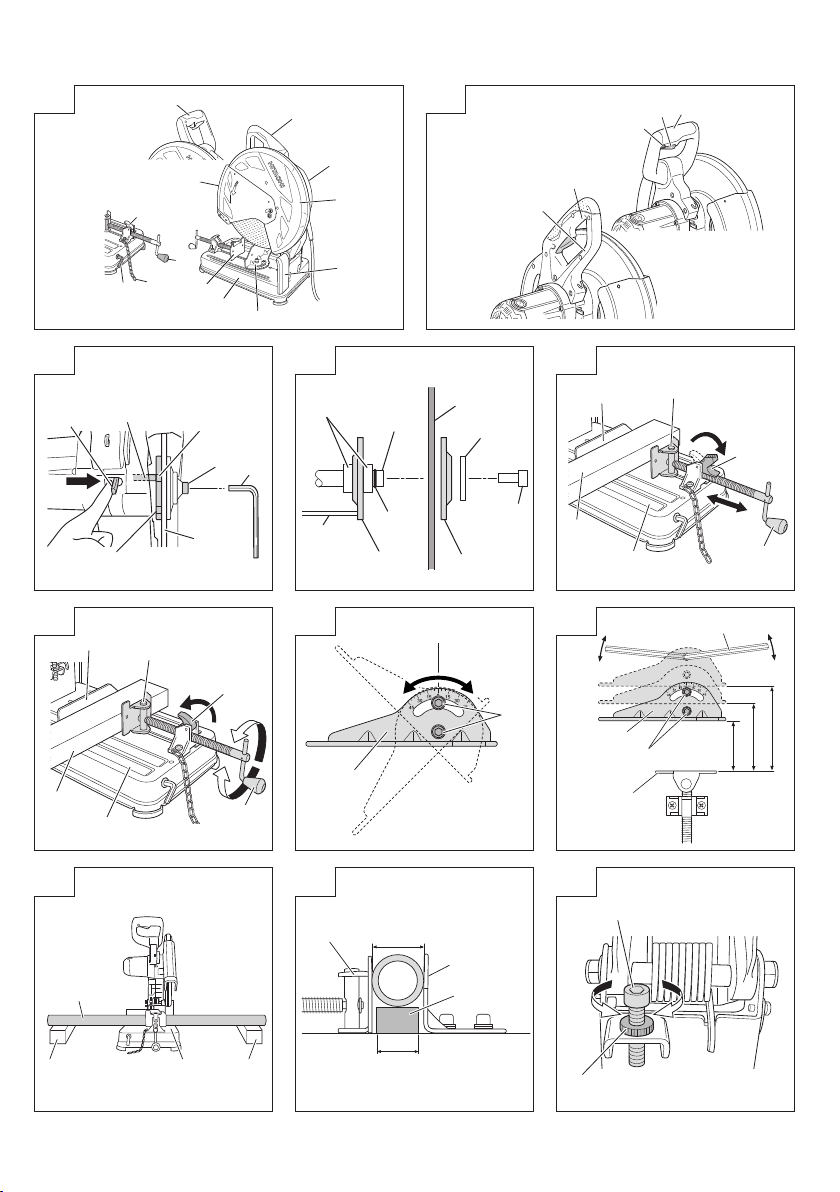
1. Dismounting the cut-off wheel (Fig. 3 and 4)
(1) Raise lower gurd (A) .
Press down on the stopper pin to bring it into contact with
the wheel washer.
Rotate the cut-off wheel, pass the stopper pin through the
hole on the wheel washer, and then remove the M10 bolt
with the hexagonal bar wrench supplied.
(2) Remove the bolt, washer (A), and the wheel washer and
detach the cut-off wheel. (Fig. 4)
CAUTION
Do not remove the O-ring or sleeve from the cut-off wheel
spindle.
2. Mounting the cut-off wheel
Throughly remove dust from the wheel washers and
bolt then mount the wheel by following the dismounting
procedures in reverse order. Return lower gurd (A) to its
original position.
CAUTION
Confi rm that the stopper which was used for installation
and removal of the cut-off wheel has returned to the
retract position.
HOW TO OPERATE
1. Procedure for fi xing the cutting material (Fig. 5
and 6)
Place the workpiece material between vise (A) and vise
(B), raise the clutch and push the screw handle to bring
vise (A) lightly into contact with the workpiece material,
as shown in Fig. 5.
Then, turn the clutch down, and securely fi x the
workpiece material in position by turning the screw
handle. When the cutting job is completed, turn the
screw handle 2 or 3 times to loosen the vise (A),
and remove the workpiece material, as shown in
Fig. 6.
CAUTION
Never remove or install a workpiece material while the
cut-off wheel is rotating, to avoid personal injury.
2. Cutting at angles (Fig. 7)
(1) The machine permits cutting at angles of 0° – 45°.
(2) Loosen the two M10 hexagon socket head bolts on the
vice (B), then set the working surface on the vice-jaw at
any angles of 0°, 30°, or 45° . Upon completion of setting,
securely tighten the two 10 mm bolts.
3. Moving the stationary vise-jaw (Fig. 8)
The vise opening is set at the maximum of
165 mm when shipped from the factory. In case an
opening of more than 165 mm is required, move the vise
to the position shown by the chain line after unscrewing
the two bolts. The maximum opening can be set in two
steps 200 mm and 235 mm. When the cutting material
is excessively wide, the vise can be eff ectively used by
repositioning the stationary side of the vise-jaws.
4. Cutting Long Workpiece Materials (Fig.9)
Make sure you place both ends of long workpiece
materials on blocks that are the same height as the base
to stabilize it prior to beginning work.
5. How to use square block (Fig. 10)
When the cut-off wheel has a reduced outer diameter,
insert between the vise (A) and (B) a square block slightly
smaller than the dimension of workpiece being cut to use
the cut-off wheel economically.
6. Adjusting the Cutting Depth (Fig. 11)
When the cut-off wheel has a reduced outer diameter,
change the height of the stopper bolt to adjust the cutting
depth. Adjustments are made by loosening the lock nut
and rotating the stopper bolt. When fi nished, retighten
the lock nut to fi x the stopper bolt in place.
It is possible to eradicate splinters depending on the
material.
CAUTION
○ Make sure the height of the stopper bolt is readjusted
when the cut-off wheel is replaced.
○ If the stopper bolt is too low, there is a chance that the
cut-off wheel will cut into the base.
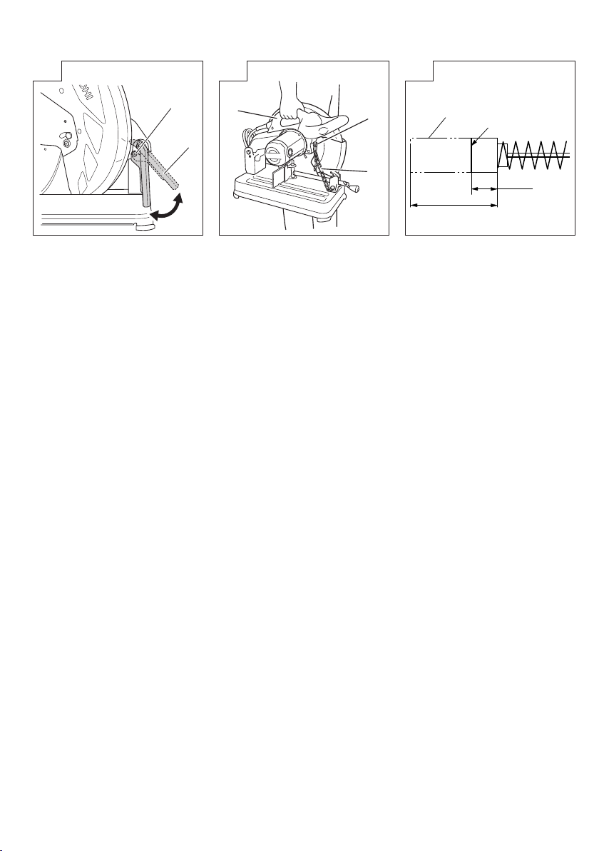
7. Adjusting the Spark Sheet (Fig.12)
Loosen the screw holding the spark sheet in place with a
Phillips screwdriver to adjust the angle.
Change the angle in accordance with the prevalent
environment and the work required to adjust the direction
in which the sparks fl y.
8. Transporting the Unit (Fig.13)
When moving the unit, attach the chain hook onto the
chain and grip the carrying handle to carry it.
MAINTENANCE AND INSPECTION
CAUTION
Be sure to switch off and pull off the plug from the power
outlet before inspection and maintenance.
1. Replacing a cut-off wheel
When the cut-off wheel has already become dull while
continually using, the unnecessary load is got from the
motor. Consequently, redress or replace a dull cut-off
wheel to ensure grinding effi ciency.
2. Inspecting the carbon brushes (Fig. 14)
The Motor employs carbon brushes which are
consumable parts. When they become worn to or near
the “wear limit”, it could result in motor trouble. When an
auto-stop carbon brush is equipped, the motor will stop
automatically. At that time, replace both carbon brushes
with new ones shown in the fi gure. In addition, always
keep carbon brushes clean and ensure that they slide
freely within the brush holders.
3. Inspecting the mounting screws
Regularly inspect all mounting screws and ensure that
they are properly tightened. Should any of the screws be
loose, retighten them immediately. Failure to do so could
result in serious hazard.
4. Replacing supply cord
If the replacement of the supply cord is necessary, this
has to be done by Hitachi Authorized Service Center in
order to avoid a safety hazard.
5. Lubrication
Supply oil in the following oil supply points once a month
so as to keep the machine workable for a long time.
Oil supply points
○ Rotary part of shaft
○ Rotary part of vise
○ Slide way of vise (A)
6
Page 8

English
6. Cleaning
Wipe off chip and waste adhered to the machine with a
cloth or the like time to time. Be careful not to make the
motor portion wet with oil or water.
7. Service parts list
CAUTION
Repair, modifi cation and inspection of Hitachi Power
Tools must be carried out by a Hitachi Authorized Service
Center.
This Parts List will be helpful if presented with the tool to
the Hitachi Authorized Service Center when requesting
repair or other maintenance.
In the operation and maintenance of power tools, the
safety regulations and standards prescribed in each
country must be observed.
MODIFICATIONS
Hitachi Power Tools are constantly being improved
and modifi ed to incorporate the latest technological
advancements.
Accordingly, some parts may be changed without prior
notice.
NOTE:
Due to HITACHI’s continuing program of research and
development, the specifi cations herein are subject to change
without prior notice.
7
Page 9

Español
PRECAUCIONES GENERALES PARA LA
OPERACIÓN
¡ADVERTENCIA! Cuando utilice herramientas eléctricas,
tome las medidas de seguridad básicas para reducir el riesgo
de incendios, descargas eléctricas, y lesiones, incluyendo
lo siguiente. Lea todas estas instrucciones antes de utilizar
este producto y guárdelas.
Para realizar operaciones seguras:
1. Mantener el área de trabajo limpia, áreas y bancos de
trabajo desordenados son causa de daños personales.
2. Considerar el medio ambiente del área de trabajo. No
exponer las herramientas eléctricas a la lluvia. No usar
herramientas eléctricas en lugares moja dos o húmedos.
Mantener el área de trabajo bien iluminada.
No utilice herramientas eléctricas cuando exista el riesgo
de incendios o de explosión.
3. Protegerse contra descargas eléctricas. Evitar el
contacto del cuerpo con las superfi cies puestas a
tierra. (p. ej., tubos, radiadores, hornos de microondas,
o refrigeradores.)
4. Mantener a los niños alejados. No dejar que los visitantes
toquen las herramientas ni los cables de extensión.
Todos los visitantes deberán mantenerse alejados del
área de trabajo.
5. Guardar las herramientas que no se usen y ponerlos en
lugares secos, altos o cerrados, fuera del alcance de los
niños.
6. No forzar las herramientas, éstas trabajarán más
y con mayor seguridad cuando cumplan con las
especifi caciones para las cuales fueron diseñadas.
7. Usar las herramientas apropiadas. No forzar pequeñas
herramientas o accesorios a realizar el trabajo de
herramientas de mayor potencia. No utilizar herramientas
para otros propósitos para los cuales no fueron
diseñadas, por ejemplo, no utilizar sierras circulares para
cortar ramas de árboles o troncos.
8. Vestir apropiadamente. No ponerse ropas que queden
fl ojas ni tampoco joyas. Estas podrian quedar atrapadas
en las partes móviles de las herramientas. Cuando se
trabaje en exteriores, se recomienda el uso de guantes
de goma y calzado que no resbale.
9. Utilice protección para los ojos. También utilice una
máscara facial o contra el polvo si la operación de corte
es polvorienta.
10. Conecte un equipo colector de polvo.
Si existen dispositivos para la conexión de equipos de
extracción y recolección de polvo, cerciórese de que
éstos estén conectados adecuadamente, y de utilizarlos
en la forma correcta.
11. Cuidar del cable. Nunca lleve las herramientas colgando
del cable, tampoco tire del cable para efectuar la
desconexión de las herramientas. Mantener el cable
alejado del calor, aceite y bordes agudos.
12. Asegurar la pieza de trabajo usando para ello
abrazaderas o un tornillo. Esto es más seguro que usar
las manos, además, ambas manos quedan libres para
operar la herramienta.
13. No extenderse excesivamente para efectuar un trabajo.
Mantener en todo momento un buen balance y base de
apoyo.
14. Mantener cuidadosamente las herramientas. Tenerlas
siempre limpias y afi ladas para obtener un mejor
rendimiento y un funcionamiento más seguro. Seguir
siempre las instrucciones para la lubricación y el cambio
de accesorios. Inspeccionar periódicamente los cables
de las herramientas y si estuviesen danãdos, hacer
que los reparen técnicos o expertos. Inspeccionar
periódicamente los cables de extensión y cambiarlos
si estuviesen dañados. Mantener los mangos secos,
limpios, y libres de aceite y grasa.
15. Desconectar las herramientas cuando no se usen, antes
de repararlas, y cuando se cambien accesorios como
por ejemplo, cuchillas, brocas, cortadores, etc.
16. Quitar las cuñas y las llaves de tuercas. Acostumbrarse
a comprobar si se han quitado las cuñas y las llaves
de tuercas antes de poner las herramientas en
funcionamiento.
17. Evitar puestas en funcionamiento sin fi n alguno. No
llevar las herramientas con los dedos en los inerruptores
mientras que éstas están conectadas. Cuando se
conecten las herramientas, cerciorarse de que los
interruptores estén en la posición de desconectados.
18. Para usos en exteriores usar cables de extensión. Cuando
las herramientas vayan a ser usadas en exteriores,
usar solamente cables de extensión diseñados para tal
propósito.
19. Estar siempre alerta y poner atención a lo que se está
haciendo, usar el sentido común y no operar con la
herramienta cuando se esté cansado.
20. Comprobar las piezas dañadas. Antes de seguir con
el funcionamiento de las herramientas, las piezas que
estén dañadas deberán comprobarse cuidadosamente
para determinar si pueden funcionar apropiadamente y
cumplir con la función para las que fueron diseñadas.
Comprobar el alineamiento y agarrotamiento de piezas
móviles, rotura de piezas, montura, y cualquier otra
anomalía que pudiese afectar al rendimiento de la
herramienta. Cualquier pieza que estuviese dañada
deberá repararse apropiadamente o cambiarse en un
centro de reparaciones autorizado, al menos que se
indique, lo contrario en este manual de instrucciones.
Procurar que los interruptores defectuosos los cambie
un centro de reparaciones autorizado.
No usar las herramientas si sus interruptores no
funcionasen apropiadamente.
21. Advertencia
La utilización de cualquier accesorio o aditivo no
recomendado en este manual de instrucciones puede
conducir al riesgo de lesiones.
22. En caso de avería, haga que su herramienta sea reparada
por un técnico cualifi cado.
Esta herramienta eléctrica está de acuerdo con los
requisitos de seguridad pertinentes. Las reparaciones
solamente deberán realizarlas técnicos cualifi cados
utilizando piezas de repuesto originales. De lo contrario,
el usuario podría lesionarse.
PRECAUCIONES SOBRE EL USO DE LA
TRONZADORA
1. Inspeccionar la rueda cortadora antes del uso. No utilizar
ruedas cortadoras rajadas o defectuosas. Antes de
usarla, efectúe una prueba para asegurarse de que la
máquina cortadora no tenga problemas.
2. Utilizar la rueda cortadora normal con su superfi cie de
trabajo normal.
3. Portegerse de las chispas.
4. Reemplazar la rueda cortadora cuando sea necesario.
5. Tener especial cuidado de que las piezas de sujeción
de la rueda cortadora no estén dañadas. Las piezas
defectuosas pueden danãr la rueda cortadora.
6. Asegurarse de que la pieza de trabajo esté libre de
cuerpos extraños tales como clavos.
7. Utilizar únicamente las ruedas cortadoras recomendadas
por el fabricante que lleven una marca de velocidad igual
o mayor que la indicada en la placa de identifi cación de
la máquina.
8
Page 10

Español
8. Las ruedas abrasivas se deben guardar y manejar con
cuidado de acuerdo con las instrucciones del fabricante.
9. Asegurarse de que la rueda se encuentre instalada de
conformidad con las instrucciones del fabricante.
10. Nunca utilizar la máquina sin el protector en su lugar.
11. No utilizar la hoja de sierra.
12. No utilizar la máquina en atmósferas ni entornos
explosivos o sea, en lugares donde las chispas puedan
causar incendio, explosión, etc.
13. Este producto no es un juguete, no deje que niños
jueguen con él.
ESPECIFICACIONES
Voltaje (por áreas)*
Acometida*
Dimensiones
máx. de corte*
Altura × Anchura
Rueda cortadora ø355 × ø25,4 × 4 mm (Rueda cortadora de resinoide reforzado)
Velocidad sin carga 3 800 / min
Velocidad periférica de trabajo máxima
Peso (Cuerpo principal solamente) 17,0 kg
*1
Verifi car indefectiblemente los datos de la placa de características de la máquina, pues varían de acuerdo al país de destino.
*2 Las dimensiones máximas de corte son las dimensiones de corte permitidas mientras la rueda cortadora no esté notablemente
gastada por el material de corte.
ACCESORIOS ESTÁNDAR
(1) Rueda cortadora .......................................................... 1
(2) Llave de barra hexagonal ............................................. 1
APLICACIÓN
Corte de diversos materiales metálicos, como tubos, barras,
acero perfi lado.
ANTES DE LA PUESTA EN MARCHA
1. Alimentación
Asegurarse de que la alimentación de red que ha de
ser utilizada responda a las exigencias de corriente
especifi cadas en la placa de características del
producto.
2. Conmutador de alimentación
Asegurarse de que el conmutador de alimentación esté
en la posición OFF (desconectado). Si la clavija está
conectada en la caja del enchufe mientras el conmutador
de alimentación esté en posición ON (conectado)
las herramientas eléctricas empezarán a trabajar
inmediatamente, provocando un serio accidente.
3. Cable de prolongación
Cuando está alejada el área de trabajo de la red de
alimentación, usar un cable de prolongación de un grosor
y potencia nominal sufi ciente. El cable de prolongación
debe ser mantenido lo más corto posible.
4. Instale la máquina sobre una superfi cie plana y nivelada,
y manténgala en condiciones de estabilidad. Antes
del envío, la máquina ha sido sometida a una rigurosa
inspección en fábrica para evitar descargas eléctricas
durante la operación.
5. Como las partes móviles están aseguradas por la tensión
de una cadena durante el transporte, extraiga dicha
cadena de su gancho empujando ligeramente el asa.
9
1
1
Forma del material
por cortar
2
A
(120 V, 127 V, 220 V, 230 V, 240 V)
2 000 W (127 V), 2 200 W
A
A
B
A
A × B
Ángulo de corte 0° 130 mm 120 mm 95 mm × 200 mm 137 mm
Ángulo de corte 45° 115 mm 104 mm 115 mm × 104 mm 100 mm
4 800 m / min
6. Asegúrese de que todas las ruedas cortadoras estén en
perfectas condiciones y que no tengan rebabas y rajas.
7. Aunque las tuercas de fi jación se han apretado
completamente en fábrica antes del envío, vuelva a
apretarlas para mayor seguridad.
8. La cubierta de esta máquina (cubierta de la rueda
cortadora) evita posibles accidentes debido a la rotura de
la rueda cortadora, etc. Aunque los tornillos de montaje
se han apretado completamente en fábrica antes del
envío, vuelva a apretarlos para mayor seguridad.
9. Cuando reemplace la rueda cortadora, asegúrese de
utilizar otra que haya sido diseñada para una velocidad
circunferencial superior a 4 800 m/min.
10. Asegúrese de que la llave de barra utilizada para apretar
o extraer la rueda cortadora no quede colocada en la
máquina.
11. Verifi que que la pieza de trabajo se encuentre
correctamente soportada. Asegúrese de que el material
esté fi rmemente apretado con el tornillo de banco. Si
no, se podrían producir serios accidentes al afl ojarse el
material, o la rueda cortadora podría romperse durante la
operación.
12. Antes del uso, asegúrese de que la rueda abrasiva se
encuentre correctamente instalada y apretada, y haga
funcionar la máquina sin carga durante 30 segundos en
condiciones de seguridad. Deténgala inmediatamente si
hay vibraciones considerables u otros defectos. En tal
caso, inspeccione la máquina para localizar la causa.
13. Gire la rueda cortadora para inspeccionar cualquier
defl exión facial. Una defl exión pronunciada causará el
desplazamiento de la rueda cortadora.
14. Cuando trabaje en condiciones polvorientas, asegúrese
de que no se obstruyan las rejillas de ventilación. En
caso de que sea necesario eliminar el polvo, primero
desconecte la máquina de la fuente de alimentación de
la red.
A
A
Page 11

Español
PROCEDIMIENTOS DE CORTE
PRECAUCIÓN
Es muy peligroso extraer o instalar la pieza de trabajo
con la máquina cortadora en funcionamiento.
1. Accionamiento del interruptor
Los usos del interruptor varían de acuerdo a la región.
La herramienta se encenderá cuando se accione el
interruptor y se apagará cuando se lo libere. (Fig. 2)
<Usos del interruptor de encendido/bloqueo>
En modelos equipados con un bloqueador de interruptor,
pulse el bloqueador de interruptor cuando el interruptor
se accione para permitir que las operaciones continúen
después de soltar el interruptor. (Fig. 2)
2. Corte
(1) Gire la rueda cortadora presionando ligeramente el asa,
y acérquela al material que desee cortar.
(2) Cuando la rueda cortadora entre en contacto con el
material, presione ligeramente hacia abajo el asa para
iniciar el corte.
(3) Cuando fi nalice el corte (o el ranurado diseñado), levante
el asa y devuélvala a la posición original.
(4) Al terminar cada proceso de corte, ponga el interruptor
en OFF a fi n de parar la rotación y efectúe el trabajo de
corte siguiente.
PRECAUCIÓN
La aplicación de más fuerza al asa no signifi ca
necesariamente un corte más rápido. Si aplica demasiada
fuerza sobre el asa el motor recibirá demasiada presión
y se reducirá su capacidad. No se olvide de poner
el interruptor en OFF, ni de desconectar el cable de
alimentación, después de haber fi nalizado la operación
de corte.
MONTAJE Y DESMONTAJE DE LA RUEDA
CORTADORA
1. Desmontaje de la rueda cortadora (Figs. 3 y 4)
(1) Levantar el protector inferior (A).
Presione el perno retenedor para que entre en contacto
con la arandela de la rueda.
Gire la rueda cortadora, pase el perno retenedor por
el orifi cio de la arandela de la rueda y, a continuación,
quite el perno M10 con la llave de barra hexagonal
suministrada.
(2) Extraiga el perno, la arandela (A), y la arandela de la
rueda cortadora, y desmonte ésta. (Fig. 4)
PRECAUCIÓN
No quite la junta tórica ni el manguito del eje de la rueda
cortadora.
2. Montaje de la rueda cortadora
Limpie cuidadosamente el polvo de las arandelas y el
perno de la rueda cortadora, y monte ésta siguiendo los
procedimientos anteriores en orden inverso. Vuelva a
colocar el protector inferior (A) en su posición original.
PRECAUCIÓN
Confi rme que el retenedor utilizado para el montaje y
desmontaje de la rueda cortadora esté replegado.
UTILIZACIÓN
1. Procedimiento de fi jación del material de corte
(Figs. 5 y 6)
Coloque el material de la pieza de trabajo entre el
tornillo de banco (A) y el tornillo de banco (B), levante el
embrague y empuje la empuñadura roscada hasta que
el tornillo de banco (A) haga un contacto ligero con el
material de la pieza de trabajo, tal como se observa en la
Fig. 5.
Luego, gire el embrague hacia abajo y fi je fi rmemente
el material de la pieza de trabajo en su lugar girando
la empuñadura roscada. Al terminar de cortar, gire la
empuñadura roscada 2 ó 3 veces para afl ojar el tornillo
de banco (A), y retire el material de la pieza de trabajo, tal
como se muestra en la Fig. 6.
PRECAUCIÓN
Para evitar lesiones personales, no retire ni instale el
material de la pieza de trabajo mientras está girando la
rueda de corte.
2. Corte en ángulo (Fig. 7)
(1) La máquina permite cortar en ángulos de 0° – 45°.
(2) Afl oje los dos pernos de cabeza hueca hexagonales M10
en el tornillo de banco (B) y, a continuación, coloque la
superfi cie de trabajo en la mordaza del tornillo de banco,
en cualquier ángulo de 0°, 30° o 45°. Después del ajuste,
apriete fi rmemente los dos pernos de 10 mm.
3. Movimiento de la mordaza estacionaria del tornillo
de banco (Fig. 8)
La abertura de las mordazas se ha ajustado en fábrica
a un máximo de 165 mm. En caso de requerirse una
abertura de más de 165 mm, mueva el tornillo de
banco hasta la posición mostrada mediante la línea de
la cadena después de desatornillar los dos pernos de
cabeza hexagonal. La abertura máxima podrá ajustarse
en dos pasos a 200 mm y 235 mm. Cuando el material
que desee cortar sea demasiado ancho, el tornillo de
banco podrá utilizarse efectivamente cambiando la
posición del lado estacionario de las mordazas del
tornillo.
4. Corte de materiales de trabajo largos (Fig. 9)
Asegúrese de colocar ambos extremos de los materiales
de trabajo largos sobre bloques de la misma altura,
utilizados como base para estabilizar la pieza de trabajo
antes de comenzar a trabajar.
5. Cómo utilizar un bloque cuadrado (Fig. 10)
Cuando el disco de corte tiene un diámetro exterior
reducido, coloque entre los tornillos de banco (A) y (B)
un bloque cuadrado apenas más pequeño que la pieza
de trabajo que se cortará, a fi n de utilizar el disco de corte
de forma económica.
6. Ajustar la profundidad de corte (Fig. 11)
Cuando el disco de corte tiene un diámetro exterior
reducido, cambie la altura del perno retenedor para
regular la profundidad del corte. Los ajustes se realizan
afl ojando la tuerca de seguridad y girando el perno
retenedor. Cuando termine, vuelva a ajustar la tuerca de
seguridad para colocar el perno retenedor en su lugar.
Es posible erradicar las astillas dependiendo del
material.
PRECAUCIÓN
○ Corrobore que se reajuste la altura del perno retenedor
cuando se cambie la rueda cortadora.
○ Si el perno retenedor está muy bajo, existe la posibilidad
de que la rueda cortadora corte hacia la base.
7. Ajuste de la hoja parachispas (Fig.12)
Afl oje el tornillo, sujetando la hoja parachispas en su
lugar, con un destornillador Phillips para regular el
ángulo.
Cambie el ángulo de acuerdo con el ambiente prevalente
y el trabajo requerido para ajustar la dirección en que
salen despedidas las chispas.
8. Transporte de la unidad (Fig.13)
Al mover la unidad, fi je el gancho para cadena en
la cadena y sujete el mango de transporte para
transportarla.
10
Page 12

Español
MANTENIMIENTO E INSPECCION
PRECAUCIÓN
Antes de inspeccionar la máquina cortadora y efectuar
su mantenimiento, asegúrese de poner el interruptor en
OFF y desconectar el enchufe del cable de alimentación
de la toma de la red.
1. Reemplazo de la rueda cortadora
Cuando se utilice continuamente una rueda cortadora
sin fi lo, el motor recibirá una carga innecesaria.
Consecuentemente, rectifi que o reemplace dicha rueda
para asegurar la máxima efi cacia de corte.
2. Inspeccionar los carbones de contacto (Fig. 14)
El motor emplea escobillas de carbón que son partes
consumibles. Cuando se gastan o están cerca del “limite
de desgaste” pueden causar problemas al motor.
Al equiparse la escobilla de carbón de parada automática,
el motor se detendrá automáticamente en ese momento
hay que proceder a cambiar ambas escobillas de
carbón por la nuevas, que tienen los mismos números
de escobillas de carbón como se muestra en la fi gura.
Además siempre hay que mantener las escobillas
de carbón limpias y asegurarse de que se muevan
libremente en sus porta-escobillas.
3. Inspeccionar los tornillos de montaje
Regularmente inspeccionar todos los tornillos de montaje
y asegurarse de que estén apretados fi rmemente. Si
cualquier tornillo estuviera suelto, volver a apretarlo
inmediatamente. El no hacer esto provocaría un riesgo
serio.
4. Sustitución del cable de alimentación
La sustitución del cable de alimentación deberá ser
realizada por un Centro de servicio autorizado de Hitachi
para evitar riesgos de seguridad.
5. Lubricación
Aplique aceite a los puntos de engrase una vez al mes
a fi n de mantener la máquina en buenas condiciones
durante mucho tiempo.
Puntos de engrase
○ Parte giratoria del eje
○ Parte giratoria del tornillo de banco
○ Parte deslizante del tornillo de banco (A)
6. Limpieza
Limpie de vez en cuando las virutas y el polvo de la
máquina utilizando un paño o algo por el estilo. Tenga
cuidado para que el motor no se moje con aceite o
agua.
7. Lista de repuestos
PRECAUCIÓN
La reparación, modifi cación e inspección de las
herramientas eléctricas Hitachi deben ser realizadas por
un Centro de Servicio Autorizado de Hitachi.
Esta lista de repuestos será de utilidad si es presentada
junto con la herramienta al Centro de Servicio Autorizado
de Hitachi, para solicitar la reparación o cualquier otro
tipo de mantenimiento.
En el manejo y el mantenimiento de las herramientas
eléctricas, se deberán observar las normas y reglamentos
vigentes en cada país.
MODIFICACIONES
Hitachi Power Tools introduce constantemente mejoras
y modifi caciones para incorporar los últimos avances
tecnológicos.
Por consiguiente, algunas partes pueden ser modifi cadas
sin previo aviso.
NOTA
Debido al programa continuo de investigación y desarrollo
de HITACHI estas especifi caciones están sujetas a cambio
sin previo aviso.
11
Page 13

Português
PRECAUÇÕES GERAIS QUANTO À OPERAÇÃO
PRECAUÇÃO! Ao usar ferramentas elétricas, observe as
precauções básicas de segurança para evitar o risco de
incêndio, choques elétricos e acidentes pessoais, inclusive
o seguinte.
Leia todas estas instruções antes de usar este equipamento,
e guarde-as em um lugar seguro.
Para operações seguras:
1. Mantenha o local de trabalho arrumado. A desordem no
local de trabalho pode ser motivo de acidentes.
2. Leve em consideração o ambiente que o rodeia. Não
exponha as ferramentas elétricas à chuva. Não use
ferramentas elétricas em locais úmidos ou molhados.
Trabalhe em um local bem iluminado.
Não use ferramentas elétricas em locais onde haja risco
de incêndios ou explosões.
3. Evite choques elétricos. Evite o contato com superfícies
conectadas à terra. (p. ex. tubos, radiadores, fogões,
refrigeradores).
4. Mantenha as crianças afastadas. Não deixe que terceiros
toquem na ferramenta ou no cabo elétrico. Não permita
que crianças permaneçam no local de trabalho.
5. Guarde as ferramentas que não estão sendo usadas.
As ferramentas que não estão sendo usadas devem ser
guardadas em um local seco, alto ou fechado, fora do
alcance de crianças.
6. Não sobrecarregue a ferramenta. O trabalho será melhor
e mais seguro se forem observados os limites indicados
para cada ferramenta.
7. Use ferramentas apropriadas. Não use ferramentas ou
acessórios pequenos para executar o trabalho de uma
ferramenta de serviço pesado. Não use ferramentas para
fi nalidades para as quais tais ferramentas não sejam
destinadas; não use, por exemplo, uma serra circular
manual para cortar galhos ou troncos de árvores.
8. Escolha o vestuário apropriado para o trabalho.
Não use roupas largas ou jóias, pois podem prender-
se em alguma peça móvel. Nos trabalhos externos,
aconselha-se o uso de luvas de borracha e sapatos que
não escorreguem. Se tiver cabelo comprido, prenda-os
com algo apropriado.
9. Use equipamentos de proteção para os olhos e mascara
facial ou de proteção contra poeira se usar este
equipamento em locais empoeirados.
10. Conecte equipamento de remoção de poeira. Se forem
fornecidos dispositivos para a conexão de equipamentos
de remoção de poeira e aspirador de pó, certifi que-se de
que sejam conectados e usados de maneira apropriada.
11. Não force o cabo elétrico. Nunca transporte a ferramenta
pelo cabo e não o puxe para desconectar o plugue da
tomada. Proteja o cabo contra o calor e evite o seu
contato com óleo e objetos cortantes.
12. Mantenha fi xa a peça a trabalhar. Use dispositivos de
fi xação ou uma morsa para prender a peça a trabalhar. É
mais seguro do que a fi xação manual e permite manejar
a ferramenta com ambas as mãos.
13. Controle sua posição. Escolha uma posição segura e
mantenha sempre o equilíbrio.
14. Realize uma manutenção cuidadosa das ferramentas.
Tenha as ferramentas sempre afi adas e limpas para que
possa trabalhar bem e em segurança. Siga as instruções
para lubrifi cação e troca de acessórios. Inspecione
periodicamente os cabos elétricos da ferramenta e,
se estiverem danifi cados, mande-os para conserto
nas ofi cinas autorizadas. Mantenha as empunhaduras
secas, limpas e livres de óleo e graxa.
15. Não mantenha a ferramenta conectada à rede elétrica.
Quando não estiver em uso ou ao trocar de acessório
como, por exemplo, cortadores, brocas e lâminas,
mantenha a máquina desconectada da rede elétrica.
16. Retire as chaves de ajuste. Habitue-se a verifi car se as
chaves de ajuste foram retiradas da ferramenta antes de
ligá-la.
17. Evite ligações involuntárias. Não transporte ferramentas
conectadas à rede elétrica com o dedo colocado no
interruptor de comando. Antes de conectar a ferramenta
à rede elétrica, certifi que-se de que o interruptor de
comando esteja desligado.
18. Use cabos de extensão para uso externo.
Ao ar livre, use apenas um cabo de extensão adequado
para este fi m.
19. Mantenha-se sempre alerta. Ao sentir-se cansado, não
use a ferramenta.
20. Verifi que se as peças apresentam danos. Antes de
continuar a usar a ferramenta, verifi que cuidadosamente
se os dispositivos de proteção e peças que apresentam
pequenos danos estão operacionais. Verifi que se as
peças móveis estão alinhadas, movimentando-se
com fl uência, se existem peças danifi cadas, se estão
perfeitamente montadas ou se existem quaisquer outros
problemas que possam afetar sua operação. Todas
as peças e dispositivos de proteção que não estejam
funcionando perfeitamente devem ser consertados ou
substituídos numa ofi cina autorizada, a menos que haja
indicações contrárias nestas instruções de uso. Não use
a ferramenta se o interruptor não ligar nem desligar.
21. Advertência
O uso de quaisquer acessórios ou aparelhos adicionais
que não se encontrem nestas instruções de uso podem
apresentar riscos de acidentes pessoais.
22. Use os serviços de pessoas qualifi cadas. Esta ferramenta
elétrica está de acordo com os requisitos de segurança
relevantes. Os consertos devem ser realizados apenas
por pessoal qualifi cado, usando peças sobressalentes
originais. Caso contrário, o usuário pode correr um risco
considerável.
PRECAUÇÕES AO USAR A CORTADORA DE
DISCO ABRASIVO
1. Inspecione o esmeril antes de usar, não utilize esmeris
lascados ou com outros tipos de defeitos. Sempre faça
um teste de funcionamento antes de usar para verifi car
se a cortadora de disco abrasivo não possui nenhuma
anormalidade.
2. Use o disco abrasivo normal em sua superfície de
trabalho normal.
3. Proteja-se contra as faíscas provocadas pela operação.
4. Substitua corretamente o disco abrasivo.
5. Esteja sempre atento para que as peças de retenção
do disco abrasivo não fi quem nunca defeituosas. Peças
com defeito causam danos ao disco abrasivo.
6. Certifi que-se de que a peça a trabalhar esteja livre de
corpos estranhos como pregos.
7. Use apenas esmeris recomentados pelo fabricante que
possuam uma velocidade marcada igual ou maior que a
velocidade marcada na placa de identifi cação da máquina.
8. Discos abrasivos devem ser armazenados e manuseados
com cuidado, de acordo com as instruções do fabricante.
9. Certifi que-se de que o disco montado foi ajustado
conforme as instruções do fabricante.
10. Não utilize nunca a máquina sem a proteção no lugar.
11. Não utilize a lâmina de serra.
12. Não utilize a máquina em atmosferas e ambientes
infl amáveis onde faíscas podem provocar incêndios,
explosões, etc.
13. Este produto não é um brinquedo, não deixe que
crianças brinquem com ele.
12
Page 14

Português
ESPECIFICAÇÕES
Voltagem (por áreas)*
Potência de entrada*
Dimensões
máximas de
2
corte*
Altura × Largura
Disco abrasivo ø355 × ø25,4 × 4 mm (Esmeris resinóides reforçados)
Rotação sem carga 3 800 / min
Velocidade máxima periférica de
trabalho
Peso (Somente do corpo principal) 17,0 kg
*1 Certifi que-se de verifi car a voltagem na placa de identifi cação no produto, pois ela está sujeita a alterações conforme a área.
*2 As dimensões de corte máximas são possíveis apenas se o disco abrasivo não estiver muito desgastado pelo uso.
1
1
Formato do material
a ser cortado
A
(120 V, 127 V, 220 V, 230 V, 240 V)
2 000 W (127 V), 2 200 W
A
A
B
A
A
A × B
Ângulo de corte 0° 130 mm 120 mm 95 mm × 200 mm 137 mm
Ângulo de corte 45° 115 mm 104 mm 115 mm × 104 mm 100 mm
4 800 m / min
A
ACESSÓRIOS PADRÕES
(1) Disco abrasivo .............................................................1
(2) Chave de barra sextavada ........................................... 1
APLICAÇÕES
Corte de vários materiais metálicos como tubos, barras
redondas e aço perfi lado.
ANTES DA OPERAÇÃO
1. Fonte de energia
Certifi que-se de que a fonte de energia que será usada
satisfaça as exigências especifi cadas na placa de
identifi cação do produto.
2. Interruptor de alimentação
Certifi que-se de que o interruptor de alimentação
esteja na posição de desligado (OFF). Se o plugue for
conectado a uma tomada elétrica com o interruptor na
posição de ligado (ON), a ferramenta elétrica começará
a funcionar imediatamente, podendo provocar um grave
acidente.
3. Cabo de extensão
Quando o local de trabalho não possuir uma fonte de
energia, use um cabo de extensão de espessura e de
potência nominal sufi cientes. A extensão deve ser
mantida o mais curta possível.
4. Instale a máquina num local nivelado e mantenha-a
em condições estáveis. Antes de sair da fábrica, o
equipamento é sujeito a uma inspeção rígida para evitar
choques elétricos durante a operação.
5. Como as peças móveis são presas pela tensão de
uma corrente durante o transporte, retire a corrente do
gancho apertando levemente o cabo do interruptor.
6. Certifi que-se de que os discos abrasivos estejam em
perfeitas condições e sem marcas e rachaduras.
7. Embora as porcas de retenção tenham sido totalmente
apertadas na fábrica antes da entrega, por medida
de segurança, reaperte-as bem antes de usar o
equipamento.
8. Possíveis acidentes como um disco abrasivo rachado
são evitados pela tampa protetora (protetor do disco).
Embora ela tenha sido totalmente presa na fábrica antes
da entrega, por medida de segurança, reaperte bem os
parafusos de fi xação.
9. Ao substituir o disco abrasivo, certifi que-se de que o
disco de corte substituto tenha uma velocidade periférica
designada acima de 4 800 m/min.
10. Certifi que-se de que a chave de barra usada para apertar
ou retirar o disco abrasivo não esteja presa na máquina.
11. Verifi que se o local do trabalho está apoiado de maneira
correta. Certifi que-se de que o material está bem preso
com o torno. Se não estiver, um acidente grave pode
acontecer caso o material se solte ou o disco abrasivo se
quebre durante a operação.
12. Antes de colocar a máquina sem carga para trinta em
funcionamento, certifi que-se de que o esmeril está
ajustado e apertado corretamente em posição segura;
se houver vibração considerável ou se outros defeitos
forem detectados pare imediatamente o funcionamento.
Caso isto ocorra, proceda a uma verifi cação na máquina
para descobrir a causa do defeito.
13. Gire o disco abrasivo para inspecionar quaisquer desvios
da face. Um grande desvio provoca deslocamento do
disco abrasivo.
14. Certifi que-se de que os orifícios de ventilação estão
desobstruídos em ambientes empoeirados. Se for
necessário limpar a poeira, desconecte primeiramente a
máquina da fonte de alimentação.
PROCEDIMENTOS DE CORTE
PRECAUÇÃO
É perigoso retirar ou instalar a peça a trabalhar enquanto
o disco abrasivo estiver girando.
1. Operação do interruptor
O uso do gatilho desligar varia de acordo com a região.
A ferramenta é acionada quando o gatilho é puxado e
desligada quando ele é solto (Fig. 2).
<Lock-on Switch Operations>
Em modelos com trava, pressione a trava com o gatilho
puxado para a ferramenta continuar funcionando depois
que o gatilho for solto. (Fig.2)
13
Page 15

Português
2. Corte
(1) Gire o disco abrasivo, pressione gentilmente o cabo
e leve o disco abrasivo para perto do material a ser
cortado.
(2) Quando o disco abrasivo entrar em contato com o
material a ser cortado, pressione ligeiramente um pouco
mais o cabo e comece a cortar.
(3) Quando o corte (ou o entalhamento designado) tiver sido
completado, levante o cabo e coloque-o na sua posição
original.
(4) Ao fi nal de cada processo de corte, desligue o interruptor
para parar a rotação e prossiga com o trabalho seguinte
de corte.
PRECAUÇÃO
Exercer mais força no cabo não corta mais rápido
necessariamente.
Força demasiada no cabo coloca uma pressão excessiva
no motor e reduz sua capacidade.
Ao terminar uma operação, certifi que-se de desligar
o interruptor e de desconectar o plugue da tomada
elétrica.
MONTAGEM E DESMONTAGEM DO DISCO
ABRASIVO
1. Desmontagem do disco abrasivo (Fig. 3 e 4)
(1) Levante o protetor inferior (A).
Pressione o pino de trava para baixo para colocá-lo em
contato com a arruela do disco.
Gire o disco abrasivo, introduza o pino de trava pelo
orifício na arruela do disco e retire o parafuso M10
usando a chave de barra hexagonal fornecida com o
equipamento.
(2) Retire o parafuso, arruela (A) e a arruela do disco e, em
seguida, desprenda o disco abrasivo. (Fig. 4)
PRECAUÇÃO
Nunca retire o anel em ‘O’ ou a manga do eixo do disco
abrasivo.
2. Montagem do disco abrasivo
Retire minuciosamente a poeira das arruelas do disco
e do parafuso e, em seguida, monte o disco seguindo
os procedimentos de desmontagem na ordem inversa.
Coloque o protetor inferior (A) de volta na posição inicial.
PRECAUÇÃO
Confi ra se o detentor usado para a instalação e remoção
do disco abrasivo voltou à sua posição retraída.
MODO DE OPERAÇÃO
1. Procedimento para prender o material de corte
(Fig. 5 e 6)
Coloque a peça a trabalhar entre o torno (A) e o torno (B),
levante a embreagem e empurre a alavanca do parafuso
para colocar o torno (A) levemente em contato com a
peça a trabalhar, como mostrado na Fig. 5.
Depois, vire a embreagem para baixo e prenda bem
a peça a trabalhar em posição, girando a alavanca do
parafuso. Quando o trabalho de corte tiver terminado,
gire a alavanca do parafuso duas ou três vezes para
desapertar o torno (A) e retire a peça, como mostrado na
Fig. 6.
PRECAUÇÃO
Para evitar ferimentos pessoais, nunca retire nem instale
a peça a trabalhar enquanto o disco abrasivo estiver
girando.
2. Corte em ângulos (Fig. 7)
(1) A máquina permite cortar em ângulos de 0° – 45°.
(2) Solte os dois parafusos hexagonais M10 no torno (B) e
posicione a superfície a ser trabalhada no torno em um
ângulo de 0°, 30° ou 45°. Depois de completar o ajuste,
aperte bem os dois parafusos de 10 mm.
3. Movimento do mordente do torno estacionário
(Fig. 8)
A abertura do torno é ajustada para o máximo de 165
mm ao sair da fábrica. No caso de se necessitar de
uma abertura de mais de 165 mm, mova o torno para
a posição mostrada pela linha da corrente depois de
desapertar os dois parafusos. A abertura máxima pode
ser ajustada em dois passos de 200 mm e 235 mm.
Ao cortar um material excessivamente largo, o torno
pode ser usado efi cazmente reposicionando-se o lado
estacionário dos mordentes do torno.
4. Corte de peças longas (Fig.9)
Antes de começar a trabalhar com peças longas,
coloque as duas extremidades da peça em blocos da
mesma altura que a base para estabilizá-la.
5. Como usar blocos quadrados (Fig. 10)
Se o disco abrasivo tiver diâmetro externo reduzido,
coloque um bloco quadrado ligeiramente menor que a
peça a ser cortada entre as mandíbulas (A) e (B) do torno
para usar o disco abrasivo de forma mais econômica.
6. Ajuste da profundidade do corte (Fig. 11)
Se o disco de corte tiver diâmetro externo reduzido,
ajuste a altura do pino de travamento para modifi car
a profundidade do corte. Para ajustar, solte a porca
de travamento, gire o pino de travamento e, quando
terminar, aperte novamente a porca para fi xar a posição
do pino.
Dependendo do material, é possível eliminar a produção
de lascas.
PRECAUÇÃO
○ Ajuste a altura do pino de travamento quando trocar o
disco abrasivo.
○ Se o pino de travamento estiver em posição baixa
demais, o disco abrasivo pode cortar a base.
7. Ajuste do protetor contra fagulhas (Fig.12)
Solte o parafuso fi xador do protetor com uma chave de
fenda para ajustar o ângulo.
Mude o ângulo de acordo com ambiente de uso e o
trabalho a ser realizado para modifi car a direção em que
as fagulhas voam.
8. Transporte da ferramenta (Fig.13)
Ao transportar a ferramenta, coloque o gancho da
corrente na corrente e segure a ferramenta pelo cabo.
MANUTENÇÃO E INSPEÇÃO
PRECAUÇÃO
Certifi que-se de desligar o interruptor de alimentação e
de desconectar o plugue da tomada elétrica antes de
realizar a inspeção e manutenção.
1. Substituição do disco abrasivo
Depois que o disco abrasivo fi car desafi ado durante o
uso continuado, há uma carga desnecessária ao motor.
Em conseqüência, retifi que ou substitua o disco abrasivo
desafi ado para assegurar a efi cácia do esmerilhamento.
2. Inspeção das escovas de carvão (Fig. 14)
O motor emprega escovas de carvão que são peças
de consumo. Quando elas estiverem gastas ou quase
chegando ao “limite de uso”, podem causar problemas
no motor. Quando o motor estiver equipado com uma
escova de carvão de parada automática, ele pára
automaticamente. Nesse momento, troque ambas as
escovas de carvão por novas que possuam o mesmo
número mostrado na ilustração. Além disso, mantenha
sempre limpas as escovas de carvão e certifi que-se de
que elas deslizem livremente nos suportes de escova.
14
Page 16

Português
3. Inspeção dos parafusos de montagem
Inspecione regularmente todos os parafusos de
montagem e certifi que-se de que estejam apertados
corretamente. Se algum deles estiver frouxo, reaperte-o
imediatamente. Deixar de fazer isso pode resultar em
graves perigos.
4. Substituir o cabo de alimentação
Se for necessária a substituição do cabo de alimentação,
esta tem de ser efectuada por um centro de assistência
autorizado da Hitachi de modo a evitar um perigo de
segurança.
5. Lubrifi cação
Coloque óleo uma vez por mês nos seguintes pontos
de suprimento para manter a máquina trabalhando por
muito tempo.
Pontos de suprimento de óleo
○ Parte giratória do eixo
○ Parte giratória do torno
○ Guia corrediça do torno (A)
6. Limpeza
Limpe de vez em quando os fragmentos e detritos que
aderiram à máquina com um pano ou algo similar. Tome
cuidado para não molhar com óleo ou com água a parte
do motor.
7. Lista de peças para conserto
PRECAUÇÃO
Os consertos, modifi cações e inspeções das
Ferramentas Elétricas da Hitachi devem ser realizados
por uma Ofi cina Autorizada da Hitachi.
Esta lista de peças pode ser útil se for apresentada com
a ferramenta na Ofi cina Autorizada da Hitachi ao solicitar
conserto ou manutenção.
Na operação e na manutenção das ferramentas
elétricas, devem-se observar as normas de segurança e
os padrões estabelecidos por cada país.
MODIFICAÇÕES
As Ferramentas Elétricas da Hitachi estão sempre sendo
aperfeiçoadas e modifi cadas para incorporar os mais
recentes avanços tecnológicos.
Dessa forma, algumas peças (isto é, números de código
e/ ou design) podem sofrer modifi cações sem aviso
prévio.
NOTA:
Devido ao contínuo programa de pesquisa e desenvolvimento
da HITACHI, as especifi cações aqui contidas estão sujeitas
a modifi cações sem aviso prévio.
15
Page 17

16
Page 18

CC14ST
1
8
7
13
16
15
14
33
32
31
61
35
A
2
4
3
11
10
9
12
18
17
34
37
36
62
39
38
64
63
5
5
6
20
22
5
19
18
16
30
29
43
42
41
40
60
77
78
80
81
65
66
67
68
69
70
71
72
73
74
75
76
79
82
83
21
25
24
23
46
45
47
49
56
57
58
59
84
85
65
88
89
28
27
26
49
50
48
49
51
53
54
55
86
87
74
73
30
A
90
17
Page 19

CC14ST
Item
No.
1 LOWER GUARD SET 1
2 LOWER GUARD SET 1
3 LOWER GUARD PAD 1
4 LOWER GUARD 1
5 RUBBER PAD 4
6 M5 NUT 1
7 M5X10 FLANGE SCREW 1
8 SUB COVER 1
9 RUBBER PAD 1
10 M6X15 FLANGE SCREW 1
11 PLATE WASHER 1
12 M5X10 FLANGE SCREW 1
13 WHEEL 1
14 M10 HEX. SOKET BOLT 1
15 FLANGE WASHER 1
16 WHEEL WASHER 2
17 O-RING 1
18 SHAFT SLEEVE 2
19 M5X25 SCREW 4
20 WHEEL COVER 1
21 GEAR SET 1
22 BALL BEARING 1
23 BEARING HOLDER 1
24 O-RING 1
25 GEAR 1
26 SPINDLE 1
27 KEY 1
28 BALL BEARING 1
29 M5 NUT 1
30 M6 NUT 2
31 SPRING 1
32 PIN SLEEVE 1
33 STOPPER PIN 1
34 ARMATURE SET 1
35 BALL BEARING 1
36 RUBBER PIN 1
37 ARMATURE 1
38 BALL BEARING 1
39 FAN GUIDE 1
40 STATOR 1
41 RUBBER SLEEVE 1
42 HOUSING 1
43 M5X55 SCREW 4
45 SWITCH 1
46 D4X10 TAPPING SCREW 1
47 HOOK 1
48 NEEDLE ROLLER 1
49 D4X16 TAPPING SCREW 10
50 M5X45 SCREW 3
51 CORD CLIP 1
53 CORD ARMOR 1
54 CORD 1
55 HANDLE SET 1
56 TAIL COVER 1
57 BRUSH HOLDER 2
58 CARBON BRUSH 2
Part Name Q’TY
Item
No.
59 BRUSH CAP 2
60 M5X8 HEX. SOKET SCREW 2
61 GEAR CASE 1
62 HINGE SHAFT 1
63 TORSION SPRING 1
64 D5X80 TAPPING SCREW 2
65 D8 RETAINER RING 2
66 VISE HANDLE 1
67 VISE SCREW 1
68 SCREW HOLDER 1
69 HEX. BAR WRENCH 1
70 WRENCH HOLDER 1
71 BASE 1
72 BASE RUBBER 4
73 D10 WASHER 2
74 M10 NUT 2
75 M6X12 SCREW 1
76 SPARK SHOOT 1
77 VISE SET 1
78 M8X30 HEX. SOKET BOLT 2
79 CHAIN 1
80 VISE NUT 1
81 ROLL PIN 1
82 D16 RETAINER RING 1
83 MOVING VISE 1
84 VISE SHAFT 1
85 D8 WASHER 1
86 M10X20 HEX. SOKET BOLT 2
87 FIXED VISE 1
88 M10X45 HEX. SOKET BOLT 1
89 M10 STOP Nut 1
90 M6X12 HEX. SOKET BOLT 1
Part Name Q’TY
18
Page 20

CC14STD
19
Page 21

Item
No.
1 Lower Guard Set 1
2 Lower Guard Pad 1
3 Lower Guard 1
4 Rubber Pad 4
5 M5×10 Flange Screw 1
6 M6×15 Flange Screw 1
7 Plate Washer 1
8 Wheel 1
9 M10×20 Hex. Soket Bolt 1
10 Flange Washer 1
11 Wheel Clamp Washer 2
12 O-ring 1
13 Shaft Sleeve 2
14 M5×25 Screw 4
15 Wheel Guard 1
16 Gear-Spindle Set 1
17 Ball Bearing 6203Z MX 1
18 Bearing Holder 1
19 O-ring 1
20 Gear 1
21 Spindle 1
22 Key 1
23 Ball Bearing 6000Z MX 1
24 M5 Nut 1
25 M6 Nut 2
26 Switch with lock 1
27 D4×10 Tapping Screw 1
28 D4×14 Tapping Screw 8
29 H Handle Set light green 1
30 Carry Handle Set 1
31 D6 Tapping Screw 2
32 Locking Spring 1
33 Pin Sleeve 1
34 Locking Pin 1
35 Armature Set 1
36 Ball Bearing 1
37 Rubber Pin 1
38 Armature 1
39 Ball Bearing 629RZ C&U 1
40 Fan Guide 1
41 Stator 1
42 Handle frame 1
43 Rubber Sleeve 1
44 Housing lignt green 1
45 M5×55 Screw 4
46 Hook 1
47 Pin 1
48 M5×45 Screw 3
49 D4×16 Tapping Screw 4
50 Cord Clip 1
51 Cord Armor 1
52 Cord 1
53 Tail Cover 1
54 Brush Holder 2
55 Carbon Brush 2
56 Brush Cap 2
57 M5×8 Hex. Soket Screw 2
Part Name Q'TY
CC14STD
Item
No.
58 Gear Case 1
59 Hinge Shaft 1
60 Torsion Spring 1
61 D5×80 Tapping Screw 2
62 D8 Retainer Ring 2
63 Vise Handle 1
64 Vise Screw Bar 1
65 Screw Bar Seat 1
66 Hex. Bar Wrench 1
67 Wrench Holder 1
68 Base 1
69 Base Rubber Foot 4
70 D10 Washer 2
71 M10 Nut 2
72 M6×12 Screw 1
73 Spark Guard 1
74 Vise Set 1
75 M8×30 Hex. Soket Bolt 2
76 Chain 1
77 Vise Nut 1
78 Roll Pin 1
79 D16 Retainer Ring 1
80 Moving Vise 1
81 Vise Shaft 1
82 D8 Washer 1
83 M10×20 Hex. Soket Bolt 2
84 Miter Fence 1
85 M10×45 Hex. Soket Bolt 1
86 M10 Stop Nut 1
87 M6×12 Hex. Soket Bolt 1
Part Name Q'TY
20
Page 22

21
Page 23

22
Page 24

Issued by
Shinagawa Intercity Tower A, 15-1, Konan 2-chome,
Minato-ku, Tokyo 108-6020, Japan
Distributed by
Avenida Isaac Newton No.286, Piso 2, Colonia Polanco Sección V,
Delegación Miguel Hidalgo, C. P. 11560
México, D. F.
Code No. C99208844 A
Printed in China
501
 Loading...