

Page 1
en
de
C 8FSHE • C 8FSHE (S) • C 8FSE • C 8FSE (S)
C8FSHE
fr
it
nl
es
pt
sv
da
no
fi
el
tr
en
Handling instructions
de
Bedienungsanleitung
fr
Mode d’emploi
it
Istruzioni per l’uso
nl
Gebruiksaanwijzing
es
Instrucciones de manejo
pt
Instruções de uso
sv
Bruksanvisning
da
Brugsanvisning
no
Bruksanvisning
fi
Käyttöohjeet
el
Οδηγίες χειρισμού
tr
Kullanım talimatları
Page 2
12
2
1
7
8
!
6
r
3
4
e
5
@
w
q
9
a
5
y
u
t
l
k
j
0
)
#
$
(
*
f
g
d
s
^
&
34
1
l
5–13/16" (148mm)
3 – ø9 mm
11–21/32" (296mm)
s
9–19/32" (244mm)
Ô
5
Ò
;
d
Ó
2
Page 3
6
2
1
7
0
f
w
Ú
a
8
¸
c
7
4
f
b
9
¢
¢
£
£
10
$
#
1
a
8
Ü
z
q
11
§
∞
¤
⁄
ª
¶
º
3
z
Page 4

12
13
15
˛
˛
#
z
z
◊
Ç
@
@
(
(
%
$
14
t
‹
16
‹
›
k
4
Page 5
17
18
‹
19
20
ª
v
i
x
j
2
p
21
7
h
7
8
ÏÏ
1
1
3
z
22 23
1
1
3
2
z
5
fl
)
&
(
^
Page 6
24
0
fi
f
8
g
25
m
,
b
n
/
.
26 27
z
¡
n
,
™
.
28
‡
29
§
¤
ª
º
Œ
·‚
30
b
°
‡
‚
b
·
›
‰
u
ⓑ
•
6
Page 7
31
ˆ
6
32
∏
Å
Í
Î
Ï
˝
î
33
„
Ø
w
o
´
s
e
r
ı
´
o
@
Á
ee
34
12mm
Â
5mm
˜
¯
¯
110V 21
230V 01
7
Page 8

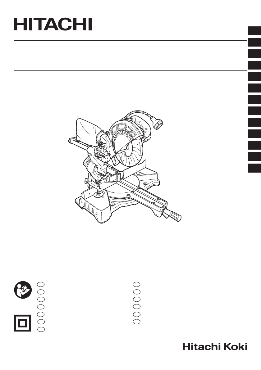
1
Handle Griff Poignée
2
Lock Lever Sperrhebel Levier de verrouillage
3
Motor Head Motorkopf Tête de moteur
4
Gear Case Getriebegehäuse Réducteur
5
Motor Motor Moteur
6
Dust Bag Staubbeutel Bacquet de réception des copeaux
7
Hinge Scharnier Charnière
8
Holder (A) Halter (A) Support (A)
Light (Only C8FSHE and
9
C8FSHE(S))
0
Indicator (For bevel scale) Anzeige (Für Fasenskala) Indicateur (Pour l’échelle de biseau)
Laser Marker
!
(Only C8FSHE and C8FSHE(S))
@
Saw Blade Sägeblatt Lame de scie
#
Vise Assembly Schraubstocksatz Ensemble d’étau
$
Fence (B) Gitter (B) Guide (B)
%
Sub Fence Hilfsführung Guide auxiliaire
^
Lever Hebel Levier
&
Side Handle Seitengriff Poignée latérale
*
Turntable Drehbühne Plaque tournante
(
Table Insert Tischeinsatz Plaque d’insertion
)
Indicator (For miter scale) Zeiger (Für Gehrungsskala) Indicateur (Pour l’échelle d’onglet)
q
Fence (A) Gitter (A) Guide (A)
w
Lower Guard Unterer Schutz Guide inférieur
e
Washer (D) Unterlegscheibe (D) Rondelle (D)
r
Spindle Cover Spindelabdeckung Couvercle de l’arbre
Switch (For laser marker)
t
(Only C8FSHE and C8FSHE(S))
y
Trigger Switch Auslöserschalter Interrupteur à détente
Switch (For light)
u
(Only C8FSHE and C8FSHE(S))
i
Marking (Pre-marked) Markierung (vormarkiert) Marquage (pré-marqué)
o
Spindle Lock Spindelhebel Verrou en fuseau
p
6 mm Flat Head Screw 6 mm Flachkopfschraube Vis à tête plate de 6 mm
a
Guard Schutz Protection
s
Base Grundplatte Socle
d
Holder Halter Support
f
Set pin Fixierstift Goupille de réglage
g
Clamp Lever Klemmhebel Levier de serrage
h
6 mm Depth Adjustment Bolt 6 mm Tiefenstellschraube
j
Slide Securing Knob Führungssicherungsknopf Bouton de fi
Adjuster (For laser marker)
k
(Only C8FSHE and C8FSHE(S))
l
Locking Pin Verriegelungsstift Goupille de verrouillage
;
6 mm Bolt 6-mm-Schraube Boulon 6 mm
z
Workpiece Werkstück Pièce
x
Auxiliary Board Hilfsbrett Carte auxiliaire
c
8 mm Depth Adjustment Bolt 8 mm Tiefenstellschraube
v
6 mm Nut 6 mm Schraubenmutter Ecrou de 6 mm
6 mm Knob Bolt
b
(Optional accessory)
n
Holder (Optional accessory) Halter (Sonderzubehör) Support (Accessoire en option)
m
Steel Square Stahlwinkel Equerre en acier
6 mm Wing Nut
,
(Optional accessory)
Height Adjustment Bolt 6 mm
.
(Optional accessory)
/
Base Surface Grundfl äche Surface du socle
English Deutsch Français
Licht (Nur C8FSHE und C8FSHE(S))
Lasermarkierer
(Nur C8FSHE und C8FSHE(S))
Schalter (Für Lasermarkierer)
(Nur C8FSHE und C8FSHE(S))
Lichtschalter
(Nur C8FSHE und C8FSHE(S))
Einstellung(Für Lasermarkierer)
(Nur C8FSHE und C8FSHE(S))
Knopfschraube, 6 mm
(Sonderzubehör)
Flügelschraube, 6 mm
(Sonderzubehör)
Höheneinstellschraube, 6 mm
(Sonderzubehör)
8
Lumière
(C8FSHE et C8FSHE(S) seulement)
Marqueur à laser
(C8FSHE et C8FSHE(S) seulement)
Interrupteur (Pour marqueur à laser)
(C8FSHE et C8FSHE(S) seulement)
Interrupteur (Pour la lumière)
(C8FSHE et C8FSHE(S) seulement)
Boulon de réglage de la profondeur
de 6 mm
Ajusteur (Pour marqueur à laser)
(C8FSHE et C8FSHE(S) seulement)
Boulon de réglage de profondeur
de 8 mm
Vis moletée de 6 mm
(Accessoire en option)
Ecrou à ailettes de 6 mm
(Accessoire en option)
Boulon de réglage de la hauteur de
6 mm (Accessoire en option)
xation du chariot
Page 9

¡
Stopper (Optional accessory) Anschlag (Sonderzubehör) Butée (Accessoire en option)
6 mm Knob Bolt
™
(Optional accessory)
£
Line Linie Ligne
¢
Warning Sign Warnzeichen Panneau de signalisation
∞
Screw Holder Schraubenhalter Support de vis
§
6 mm Wing Bolt (B) 6-mm-Flügelschraube (B) Boulon à oreilles de 6 mm (B)
¶
Vise Shaft Schraubstockachse Arbre d’étau
•
Light lens Lichtlinse Lentille lumineuse
ª
Fence Gitter Guide
º
6 mm Wing Bolt (A) 6-mm-Flügelschraube (A) Boulon à oreilles de 6 mm (A)
⁄
Vise Plate Schraubstockbacke Talon
¤
Knob Knopf Bouton
‹
Laser line Laserlinie Raie laser
›
Groove Nut Rainure
fi
Bevel Scale Schrägschnittskala Echelle de biseau
fl
Miter Scale Gehrungsskala Echelle d’onglet
Crown molding Vise Ass’y
‡
(Optional accessory)
6 mm Wing Nut
°
(Optional accessory)
Crown molding Stopper (L)
·
(Optional accessory)
Crown molding Stopper (R)
‚
(Optional accessory)
Œ
Crown molding Kronenform Corniche à courbe complexe
„
10 mm Box Wrench 10 mm Steckschüssel Clé à écrous de 10 mm
´
Bolt Schraube Boulon
‰
Light Licht Lumière
ˇ
Wear limit line Verschleißgrenze Repère de limite d’usure
Á
Collar (A) Manschette (A) Collier (A)
¨
6 mm Knob Bolt Knopfschraube, 6 mm Vis moletée de 6 mm
î
Duct Kanal Conduit
Ø
Right angle Rechter Winkel Angle droit
∏
Dust extractor Staub-Absaugung Extracteur de poussière
Å
Hose (id 38 mm × 3 m long) Schlauch (id 38 mm × 3 m lang) Tuyau (38 mm id × 3 m de long)
Adapter (Dust extractor's standard
Í
accessory)
Î
Joint (Optional accessory) Gelenk (Sonderzubehör) Joint (accessoire en option)
Dust collection adapter
Ï
(Optional accessory)
˝
Hose band (Optional accessory) Schlauchschelle (Sonderzubehör)
Ó
Work bench Werkbank Établi
Ô
8 mm Bolt 8-mm-Schraube Boulon 8 mm
8 mm Nut 8 mm Schraubenmutter Ecrou de 8 mm
Ò
25 mm thick bench 25 mm dicke Sitzbank 25 mm d’épaisseur de banc
8 mm Bolt (B)
Ú
(Stopper for left 45° bevel angle)
¸
8 mm Bolt (A) (Stopper for 0°) 8 mm Bolzen (A) (Stopper für 0°) Boulon 8 mm (A) (Butée pour 0°)
˛
6 mm Machine screw 6 mm Maschinenschraube Vis d'assemblage 6 mm
Ç
Right angle cutting Rechter Winkel Schneiden Coupe angle droit
◊
Left bevel angle cutting
ı
6 mm Bolt 6-mm-Schraube Boulon 6 mm
˜
Brush cap Bürstenkappe Capuchon de balais
Â
Wear limit Verschleißgrenze Limite d’usure
¯
No. of carbon brush Nr. der Kohlebürste No. du balai en carbone
English Deutsch Français
Knopfschraube, 6 mm
(Sonderzubehör)
Schraubstocksatz für Kronenform
(Sonderzubehör)
Flügelmutter, 6 mm (Sonderzubehör)
Kronenformanschlag (L)
(Sonderzubehör)
Kronenformanschlag (R)
(Sonderzubehör)
Adapter (Staub-Absaugung
Standard-Zubehör)
Staubsammler-Adapter
(Sonderzubehör)
8 mm Bolzen (B) (Stopper für linken
45° abgeschrägten Winkel)
Linker abgeschrägter Winkel
Schneiden
9
Vis moletée de 6 mm
(Accessoire en option)
Ensemble d’étau de corniche à
courbe complexe
(Accessoire en option)
Ecrou à ailettes de 6 mm
(Accessoire en option)
Butée de corniche à courbe
complexe (L) (Accessoire en option)
Butée de corniche à courbe
complexe (R) (Accessoire en option)
Adaptateur (accessoire standard
d'extracteur de poussière)
Adaptateur de collecte de poussière
(accessoire en option)
Collier de serrage de tuyau
(accessoire en option)
Boulon 8 mm (B)
(Butée pour un angle de biseau
gauche de 45°)
Coupe en biseau de l'angle gauche
Page 10

1
Manico Greep Empuñaradura
2
Leva di blocco Vergrendelgreep Palanca de bloqueo
3
Testa motore Motorkop Cabezal del motor
4
Cassa ingranaggi Tandwielkast Caja de engranajes
5
Motore Motor Motor
6
Raccoglipolvere Stofzak Bolsa para el polvo
7
Cardine Scharnier Bisagra
8
Supporto (A) Houder (A) Soporte (A)
9
Luce (Solo C8FSHE e C8FSHE(S))
0
Indicatore (Per scala di smussatura) Indicator (Voor afschuiningsschaal) Indicador (Para escala de bisel)
Marcatore laser
!
(Solo C8FSHE e C8FSHE(S))
@
Lama sega Zaagblad Cuchilla de sierra
#
Gruppo morsa Bankschroef Conjunto del tornillo de carpintero
$
Guida de appoggio (B) Geleider (B) Protección (B)
%
Guida secondaria Sub-geleider Tope-guía secundario
^
Leva Hendel Palanca
&
Manico laterale Zijgreep Asa lateral
*
Piatto girevole Draaitafel Plataforma
(
Inserimento tavola Tafel-inzetstuk Inserto de mesa
)
Indicatore (Per la scala di quartabuono)
q
Guida de appoggio (A) Geleider (A) Protección (A)
w
Protezione inferiore Onderste afscherming Protector inferior
e
Rondella (D) Sluitring (D) Arandela (D)
r
Coperchio dell’alberino Drijfas-afdekking Cubierta de husillo
Interruttore (Per marcatore laser)
t
(Solo C8FSHE e C8FSHE(S))
y
Interruttore a grilletto Startschakelaar Gatillo
Interruttore (Per luce)
u
(Solo C8FSHE e C8FSHE(S))
i
Marcatura (pre-contrassegnato) Markering (voorgemarkeerd) Marcaje (pre-marcado)
o
Fermo dell’alberino Spilvergrendeling Seguro del eje
p
Vite a testa piatta 6 mm 6 mm schroef met platte kop Tornillo de cabeza plana 6 mm
a
Schermo protettivo Bescherming Protector
s
Base Basis Base
d
Supporto Houder Soporte
f
Perno di impostazione Instelpen Pasador de fi jación
g
Leva morsetto Klemhendel Palanca de fi jación
Bullone di regolazione della
h
profondità 6 mm
j
Manopola di fi ssaggio slitta Schuifvastzetknop
Regolatore (Per marcatore laser)
k
(Solo C8FSHE e C8FSHE(S))
l
Perno di blocco Vergrendelpen Pasador de bloqueo
;
Bullone da 6 mm 6 mm bout Perno de 6 mm
z
Pezzo da lavorare Werkstuk Pieza de trabajo
x
Pannello ausiliario Hulpplaat Panel auxiliar
Bullone di regolazione profondità
c
da 8 mm
v
Dado 6 mm 6 mm moer Tuerca 6 mm
Bullone a manopola da 6 mm
b
(Accessorio opzionale)
n
Supporto (Accessori opzionali) Houder (Optionele toebehoren) Soporte (Accessorio opcionales)
m
Quadrato di acciaio Stalen winkelhaak Escuadra de acero
Dado ad alette da 6 mm
,
(Accessorio opzionale)
Bullone di regolazione altezza da 6
.
mm (Accessorio opzionale)
Italiano Nederlands Español
Lamp (Alleen C8FSHE en C8FSHE(S))
Lasermarkeerinrichting
(Alleen C8FSHE en C8FSHE(S))
Indicator (Voor verstekschaal) Indicador (Para escala de ingletes)
Schakelaar
(Voor lasermarkeerinrichting)
(Alleen C8FSHE en C8FSHE(S))
Schakelaar (Voor lamp)
(Alleen C8FSHE en C8FSHE(S))
6 mm diepte-afstelbout Perno de ajuste de profundidad 6mm
Afsteller (Voor lasermarkeerinrichting)
(Alleen C8FSHE en C8FSHE(S))
8 mm diepte-stelbout
6 mm knopbout
(Optioneel toebehoren)
6 mm vleugelmoer
(Optioneel toebehoren)
Hoogte-afstelbout 6 mm
(Optioneel toebehoren)
10
Luz (Sólo C8FSHE y C8FSHE(S))
Marcador láser
(Sólo C8FSHE y C8FSHE(S))
Interruptor (Para marcador láser)
(Sólo C8FSHE y C8FSHE(S))
Interruptor (Para luz)
(Sólo C8FSHE y C8FSHE(S))
Perilla de inmovilización de
deslizamiento
Ajustador (Para marcador láser)
(Sólo C8FSHE y C8FSHE(S))
Perno de ajuste de profundidad de
8 mm
Perno de perilla de 6 mm
(Accesorio opcional)
Tuerca de aletas de 6 mm
(Accesorio opcional)
Perno de ajuste de altura de 6 mm
(Accesorio opcional)
Page 11

/
Superfi cie della base Voetplaat Superfi cie de la base
¡
Fermo (Accessori opzionali) Aanslag (Optionele toebehoren) Retén (Accessorio opcionales)
Bullone a manopola da 6 mm
™
(Accessorio opzionale)
£
Riga Streep Cuerda
¢
Segnale di avvertimento Waarschuwingssymbool Signo de advertencia
∞
Portavite Schroefhouder Sujetador de rosca
§
6 mm vite ad alette (B) 6 mm vleugelbout (B) 6 mm perno de ala (B)
¶
Albero della morsa Bankschroefas Eje de tornillo de banco
•
Lente della luce Lamplens Lente de luz
ª
Guida di appoggio Geleider Protrección
º
6 mm vite ad alette (A) 6 mm vleugelbout (A) 6 mm perno de ala (A)
⁄
Piastra morsa Klemplaat Placa de tornillo
¤
Manopola Knop Perilla
‹
Linea laser Laserstreep Línea de láser
›
Scanalatura Groef Ranura
fi
Scala di smussatura Afschuinschaal Escala en bisel
fl
Scala di quartabuono Verstekschaal Escala de ingletes
Gruppo morsa di modanatura a
‡
corona (Accessorio opzionale)
Dado ad alette da 6 mm
°
(Accessorio opzionale)
Fermo per modanatura a corona (L)
·
(Accessorio opzionale)
Fermo per modanatura a corona (R)
‚
(Accessorio opzionale)
Œ
Modanatura a corona Kroonvorm Moldura en vértice
„
Chiave chisa de 10 mm 10 mm naafbussleutel Lllave de tubo de 10 mm
´
Bullone Schroef Perno
‰
Luce Lamp Luz
ˇ
Riga di limite usura Slijtagegrens Línea de límite de desgaste
Á
Collarino (A) Kraag (A) Casquillo (A)
¨
Bullone a manopola da 6 mm 6 mm knopbout Perno de perilla de 6 mm
î
Dotto Leiding Conducto
Ø
Angolo destro Juiste hoek Ángulo recto
∏
Estrattore polvere Stofafzuiger Extractor de polvo
Tubo fl essibile
Å
(38 mm × 3 m di lunghezza)
Adattatore (accessorio standard
Í
dell’estrattore polvere)
Î
Giunto (accessorio opzionale) Verbinding (Optioneel toebehoren) Acople (Accesorio opcional)
Adattatore raccolta polvere
Ï
(accessorio opzionale)
Fascetta stringitubo
˝
(accessorio opzionale)
Ó
Banco di lavoro Werkbank Banco de trabajo
Ô
Bullone da 8 mm 8 mm bout Perno de 8 mm
Dado 8mm 8 mm moer Tuerca 8 mm
Ò
Banco da 25 mm di spessore 25 mm dikke bank Banco de 25 mm de grosor
Bullone da 8 mm (B) (fermo per
Ú
angolo di smussatura sinistro a 45°)
¸
Bullone da 8 mm (A) (fermo per 0°) 8 mm bout (A) (stopper voor 0°) Perno de 8 mm (A) (Tope para 0°)
˛
Vite da macchina da 6 mm 6 mm machineschroef Tornillo de la máquina de 6 mm
Ç
Taglio angolo destro Juiste hoek snijden Corte de ángulo recto
◊
Taglio angolo di smussatura sinistro Linkse hellingshoeksnijden
ı
Bullone da 6 mm 6 mm bout Perno de 6 mm
˜
Tappo della spazzola Borstelkap Protección de cepillo
Â
Limite di usura Slijtagegrens Límite de uso
¯
N. della spazzola di carbone Nr. van de koolborstel No. de carbón de contacto
Italiano Nederlands Español
6 mm knopbout
(Optioneel toebehoren)
Kroonvormklem
(Optioneel toebehoren)
6 mm vleugelmoer
(Optioneel toebehoren)
Kroonvormstopper (L)
(Optioneel toebehoren)
Kroonvormstopper (R)
(Optioneel toebehoren)
Slang (id 38 mm × 3 m lang)
Adapter (standaardaccessoire
stofafzuigunit)
Stofverzameladapter
(Optioneel toebehoren)
Slangband (Optioneel toebehoren) Abrazadera (Accesorio opcional)
8 mm bout (B)
(Stopper voor links 45° hellingshoek)
Perno de perilla de 6 mm
(Accesorio opcional)
Conj. de tornillo de carpintero para
moldura en vértice (Accesorio opcional)
Tuerca de aletas de 6 mm
(Accesorio opcional)
Retén de moldura en vértice (L)
(Accesorio opcional)
Retén de moldura en vértice (R)
(Accesorio opcional)
Manguera
(id 38 mm × 3 m de longitud)
Adaptador (accesorio estándar del
extractor de polvo)
Adaptador de recolección de polvo
(Accesorio opcional)
Perno de 8 mm (B) (Tope para el
ángulo de biselado izquierdo de 45°)
Corte en ángulo de biselado izquierdo
11
Page 12

1
Empunhadeira Handtag Håndtag
2
Alavanca de bloqueio Låsarm Låsearm
3
Cabeça do motor Motorhuvud Motorhoved
4
Caixa de engrenagens Växelhus Gearkasse
5
Motor Motor Motor
6
Coletor de poeira Dammpåse Støvpose
7
Dobradiça Gångjärn Hængsel
8
Empunhadeira (A) Hållare (A) Holder (A)
9
Luz (Apenas C8FSHE e C8FSHE(S))
0
Indicador (Para escala de bisel) Indikator (För vinkelskala) Indikator (For geringsskala)
Marcador a laser
!
(Apenas C8FSHE e C8FSHE(S))
@
Lâmina de serra Sågklinga Savklinge
#
Conjunto de morsa Skruvstycke Skruestik
$
Guia (B) Staket (B) Bakke (B)
%
Subguia Understaket Under-anlægsfl ade
^
Alavanca Spak Arm
&
Empunhadeira lateral Sidohandtag Sidehåndtag
*
Mesa rotatória Roterande skiva Drejebord
(
Calço de mesa Bordsinlägg Maskinbordsindsats
)
Indicador (Para régua de entalhe) Indikator (För gerskala) Indikator (For geringsskala)
q
Guia (A) Staket (A) Bakke (A)
w
Guarda da lâmina inferior Undre skydd Nedre skærmplade
e
Arruela (D) Bricka (D) Spændeskive (D)
r
Protetor da haste Spindelkåpa Spindeldæksel
Interruptor (Para marcador a laser)
t
(Apenas C8FSHE e C8FSHE(S))
y
Gatilho do interruptor Avtryckare Trykkerkontakt
Interruptor (Para luz)
u
(Apenas C8FSHE e C8FSHE(S))
i
Marca (pré-marcada) Markering (Markerad i förväg) Markering (Forudmarkeret)
o
Trava da haste Spindellås Drejeaksellås
p
Parafuso de cabeça plana de 6 mm 6 mm platthuvad skruv 6 mm fl adhovedet skrue
a
Guarda Skydd Skærmplade
s
Base Basplatta Grundplade
d
Alça Hållare Holder
f
Pino de fi xação Fästsprint Fastgørelsesstift
g
Alavanca de aperto Spännstång Klemmehåndtag
Parafuso de ajuste de profundidade
h
de 6 mm
j
Botão bloqueador do deslizamento Låsratt släde Glidesikringsgreb
Ajustador (Para o marcador a laser)
k
(Apenas C8FSHE e C8FSHE(S))
l
Pino de travamento Låsbult Låsestift
;
Parafuso de 6 mm Bult 6mm 6 mm-bolt
z
Peça de trabalho Arbetsstycke Arbejdsstykke
x
Quadro Auxiliar Hjälpbord Hjælpebræt
Parafuso de ajuste de profundidade
c
de 8 mm
v
Porca de 6 mm 6 mm mutter 6 mm møtrik
Parafuso de botão de 6 mm
b
(Acessório opcional)
n
Alça (Acessório opcional) Hållare (Valfria tillbehör) Holder (Ekstratilbehør)
m
Régua de aço Stålvinkelhake Stålfi rkant
Porca de asas de 6 mm
,
(Acessório opcional)
Parafuso de ajuste de altura de 6 mm
.
(Acessório opcional)
/
Superfície de base Basyta Grundpladefl ade
Português Svenska Dansk
Ljus (Endast C8FSHE och C8FSHE(S))
Lasermarkör
(Endast C8FSHE och C8FSHE(S))
Strömbrytare (För lasermarkör)
(Endast C8FSHE och C8FSHE(S))
Kontakt (För ljus)
(Endast C8FSHE och C8FSHE(S))
6mm djupjusteringsbult 6 mm dybdejusteringsbolt
Justering (För lasermarkör)
(Endast C8FSHE och C8FSHE(S))
8 mm djupjusteringsskruv 8 mm dybdejusteringskrue
6 mm rattbult (Tillval) 6 mm-knopbolt (Valgfrit tilbehør)
6 mm vingmutter (Tillval) 6 mm-vingeskrue (Valgfrit tilbehør)
Höjdjusteringsbult 6 mm (Tillval)
12
Lampe (Kun C8FSHE og C8FSHE(S))
Laserindikator
(Kun C8FSHE og C8FSHE(S))
Kontakt (Til laserindikator)
(Kun C8FSHE og C8FSHE(S))
Kontakt (Til lampe)
(Kun C8FSHE og C8FSHE(S))
Justeringsknap (Til laserindikator)
(Kun C8FSHE og C8FSHE(S))
Højdejusteri ngsbolt 6 mm
(Valgfrit tilbehør)
Page 13

¡
Trava (Acessório opcional) Stoppare (Valfria tillbehör) Stopper (Ekstratilbehør)
Parafuso de botão de 6 mm
™
(Acessório opcional)
£
Linha Linje Linje
¢
Sinal de aviso Varningstecken Advarselssignal
∞
Suporte do parafuso Skruvhållare Skrueholder
§
Parafuso de Borboleta de 6 mm (B) 6 mm Vingbult (B) 6 mm Vingebolt (B)
¶
Veio do torno Skruvstycke Tvingestang
•
Lente de luz Ljuslins Lampelinse
ª
Guia Staket Bakke
º
Parafuso de Borboleta de 6 mm (A) 6 mm Vingbult (A) 6 mm Vingebolt (A)
⁄
Placa da morsa Tvingplatta Skruetvingeplade
¤
Botão Ratt Håndtag
‹
Linha a laser Laserlinje Laserlinje
›
Sulco Spår Not
fi
Régua de inclinação Vinkelskala Skråningsskala
fl
Régua de entalhe Gerskala Geringsskala
Conjunto de morsa de moldura da
‡
coroa (Acessório opcional)
Porca de asas de 6 mm
°
(Acessório opcional)
Obturador de moldura da coroa (L)
·
(Acessório opcional)
Obturador de moldura da coroa (R)
‚
(Acessório opcional)
Œ
Moldura da coroa List Kroneform
„
Chave de caixa de 10 mm 10 mm Hysnyckel 10 mm topnøgle
´
Parafuso Bult Bolt
‰
Luz Ljus Lampe
ˇ
Linha de limite de desgaste Förslitningsgräns Slidgrænse
Á
Colar (A) Stoppring (A) Manchet (A)
¨
Parafuso de botão de 6 mm 6 mm rattbult 6 mm-knopbolt
î
Conduta Trumma Kanal
Ø
Ângulo reto Rät vinkel Højre vinkel
∏
Extrator de pó Industridammsugare Støvsuger
Mangueira (id 38 mm × 3 m de
Å
comprimento)
Adaptador (Acessório padrão do
Í
extrator de pó)
Î
Junta (Acessório opcional) Fog (Tillval) Samleled (Valgfrit tilbehør)
Adaptador de recolha de pó
Ï
(Acessório opcional)
Banda da mangueira (Acessório
˝
opcional)
Ó
Bancada de trabalho Arbetsbänk Arbejdsbænk
Ô
Parafuso de 8 mm Bult 8 mm 8 mm-bolt
Porca de 8 mm 8 mm mutter 8 mm møtrik
Ò
Bancada com 25 mm de espessura 25 mm tjock bänk 25 mm tyk bænk
Parafuso de 8 mm (B)
Ú
(Bujão para o ângulo de inclinação
para a esquerda de 45°)
¸
Parafuso de 8 mm (A) (Bujão para 0°)
˛
Parafuso de 6 mm para máquina 6 mm maskinskruv 6 mm maskinskrue
Ç
Corte em ângulo reto Höger vinkelkapning Skæring af ret vinkel
Corte de ângulo de inclinação para
◊
a esquerda
ı
Parafuso de 6 mm Bult 6mm 6 mm-bolt
˜
Tampa da escova Borsthätta Børstehætte
Â
Limite de desgaste Avnötningsgräns Slidgrænse
¯
N° de escova de carvão Nr. på kolborste Kul nr.
Português Svenska Dansk
6 mm rattbult (Tillval) 6 mm-knopbolt (Valgfrit tilbehør)
Listhållare (Tillval) Kroneformtvinge (Valgfrit tilbehør)
6 mm vingmutter (Tillval) 6 mm-vingeskrue (Valgfrit tilbehør)
Liststopp (L) (Tillval)
Liststopp (R) (Tillval)
Slang (id 38 mm x 3 m lång) Slange (id 38 mm x 3 m lang)
Adapter (standardtillbehör
industridammsugare)
Adapter till damminsamling (Tillval) Støvsamleradapter (Valgfrit tilbehør)
Slangband (Tillval) Slangebånd (Valgfrit tilbehør)
8 mm bult (B)
(Stoppare för vänster 45° fasvinkel)
8 mm bult (B) (stoppare för 0°) 8 mm bolt (B) (stopper for 0°)
Vänster fasvinkelkapning Skæring af venstre skrå vinkel
13
Kroneformstopper (L) (Valgfrit
tilbehør)
Kroneformstopper (R)
(Valgfrit tilbehør)
Adapter (standardtilbehør til
støvsuger)
8 mm bolt (B)
(stopper for 45° skrå vinkel mod
venstre)
Page 14

1
Håndtak Kahva Χερούλι
2
Låse spak Lukkovipu Μοχλός ασφάλισης
3
Motorenhet Moottoripää Κεφαλή Μοτέρ
4
Girkasse Vaihdelaatikko Θήκη Ταχυτήτων
5
Motor Mootori Μοτέρ
6
Støvpose Pölypussi Σακούλα Σκόνης
7
Gangjern Sarana Μεντεσές
8
Holder (A) Pidin (A) Στήριγμα (A)
Lampe
9
(Bare C8FSHE og C8FSHE(S))
0
Indikator (For fasskala) Osoitin (Viistoasteikolle) Δείκτης (Για την κλίμακα κλίσης)
Lasermarkør
!
(Bare C8FSHE og C8FSHE(S))
@
Sagblad Sahanterä Πριονωτή Λάμα
#
Skruestik Ruuvipuristin Συγκρότημα Μέγγενης
$
Vern (B) Ohjauslaite (B) Οδηγός (Β)
%
Hjelpevern Sivusuoja Δευτερεύον Οδηγός
^
Hendel Vipu Μoχλός
&
Sidehåndtak Sivukahva Πλευρικό Χερούλι
*
Dreieskive Tasauspöytä Περιστροφική Πλάκα
(
Bordinnsats Pöydän pisto-osa Τεμάχιο τροφοδοσίας
)
Indikator (For gjæringsskala) Merkkivalo (Viistekulma-asteikolle) Δείκτης (Για την κλίμακα λοξοτομής)
q
Vern (A) Ohjauslaite (A) Οδηγός (Α)
w
Nedre vern Alempi suojus Κάτω προφυλακτήρας
e
Underlagsskive (D) Välilevy (D) Ροδέλα (D)
r
Spindeldeksel Karan suojus Κάλυμμα Άξονα
Bryter (For lasermarkør)
t
(Bare C8FSHE og C8FSHE(S))
y
Startbryter Liipaisukytkin Σκανδάλη Διακόπτης
Bryter (For lampen)
u
(Bare C8FSHE og C8FSHE(S))
i
Merking (Pre-markert) Merkintä (Esimerkitty) Σημάδι (προσημειωμένο)
o
Spindellås Akselin lukko Ασφάλεια Άξονα
p
6 mm Flathodet Skrue 6mm:n tasapäinen ruuvi 6 mm Βίδα με επίπεδη κεφαλή
a
Vern Suojus Προφυλακτήρας
s
Fot Runko Βάση
d
Holder Pidin Στήριγμα
f
Sette pinne Asetustappi Περόνη ρύθμισης
g
Strekkspak Kiristimen vipu Μοχλός Σύσφιξης
h
6mm Dybdejusteringsbolt 6mm:n syvyyden säätöpultti 6 mm Μπουλόνι ρύθμισης βάθους
j
Skyvelåseknapp Liukukiinnitysnuppi Κουμπί αναστολής ολίσθησης
Justering (For lasermarkør)
k
(Bare C8FSHE og C8FSHE(S))
l
Låsestift Lukitustappi Περόνη Ασφαλείας
;
6 mm bolt 6 mm pultti 6 mm Μπουλόνι
z
Arbeidsemne Työstökappale Αντικείμενο εργασίας
x
Hjelpe Planke Apulevy Βοηθητικός πάγκος
c
8 mm dybdejusteringsskrue 8 mm syvyyden säätöruuvi Μπουλόνι ρύθμισης βάθους 8 mm
v
6mm Mutter 6mm:n mutteri 6 mm παξιμαδι
b
6 mm fi ngerbolt (Tilleggsutstyr)
n
Holder (Ekstrautstyr) Pidike (Lisävaruste) Στήριγμα (Προαιρετικό εξάρτημα)
m
Stålvinkel Teräsneliö Ατσαλένιος Γνώμονας
,
6 mm vingemutter (Tilleggsutstyr)
Høydejusteri ngsbolt 6 mm
.
(Tilleggsutstyr)
/
Verktøysfotens overfl ate Alustan pinta Επιφάνεια Βάσης
¡
Stopper (Ekstrautstyr) Pysäytin (Lisävaruste) Αναστολέας (Προαιρετικό εξάρτημα)
Norsk Suomi Ελληνικά
Lamppu
(Vain C8FSHE ja C8FSHE(S))
Lasermerkki
(Vain C8FSHE ja C8FSHE(S))
Kytkin (Lasermerkille)
(Vain C8FSHE ja C8FSHE(S))
Katkaisija (Lampulle)
(Vain C8FSHE ja C8FSHE(S))
Säädin (Lasermerkille)
(Vain C8FSHE ja C8FSHE(S))
6 mm nuppipultti
(Erillinen lisävaruste)
6 mm siipimutteri
(Erillinen lisävaruste)
Korkeuden säätöpultti 6 mm
(Erillinen lisävaruste)
14
Λυχνία
(Μόνο στο C8FSHE και C8FSHE (S))
Δείκτης λέιζερ
(Mόvo yα το C8FSHE και C8FSHE (S))
Διακόπτης (Για το δείκτη λέιζερ)
(Μόνο για το C8FSHE και C8FSHE (S))
Διακόπτης (για τη λυχνία)
(Mόvo yα το C8FSHE και C8FSHE (S))
Ρυθμιστής (Για το δείκτη λέιζερ)
(Mόvo yα το C8FSHE και C8FSHE (S))
6 mm Φτερωτό μπουλόνι
(Προαιρετικό εξάρτημα)
6 mm Φτερωτό Παξιμάδι
(Προαιρετικό εξάρτημα)
Μπουλόνι Ρύθμισης Ύψους
6 mm (Προαιρετικό εξάρτημα)
Page 15

Norsk Suomi Ελληνικά
™
6 mm fi ngerbolt (Tilleggsutstyr)
£
Linje Linja Γραμμή
¢
Fareskilt Varoitusmerkki Προειδοποιητικό σήμα
∞
Skrueholder Ruuvinpidin Στήριγμα Βίδας
§
6 mm Vinge Bolt (B) 6 mm Siipipultti (B) 6 mm Φτερωτό μπουλόνι (Β)
¶
Skrustikke aksel Ruuvipenkin akseli Άξονας μέγγενης
•
Lampens linseglass Lampun linssi Φακός λυχνίας
ª
Vern Ohjauslaite Οδηγός
º
6 mm Vinge Bolt (A) 6 mm Siipipultti (A) 6 mm Φτερωτό Μπουλόνι (A)
⁄
Skruestikkeplate Ruuvipenkin levy Πλάκα Μέγγενης
¤
Knott Nuppi Κουμπί
‹
Laserlinje Laserlinja Γραμμή λέιζερ
›
Spor Vako Αυλάκωση
fi
Fasskala Viistoasteikko Κλίμακα κλίσης
fl
Gjæringsskala Viistekulma-asteikko Κλίμακα Λοξοτομής
Krone med tvingeenhet
‡
(Tilleggsutstyr)
°
6 mm vingemutter (Tilleggsutstyr)
·
Kronestopper (L) (Tilleggsutstyr)
‚
Kronestopper (R) (Tilleggsutstyr)
Œ
Krone Kruununvalu Διαμόρφωση Κορνίζας
„
10 mm Pipenøkkel 10 mm Holkkiavain 10 mm Κοίλο Κλειδί
´
Bolt Pultti Μπουλόνι
‰
Lampe Lamppu Λυχνία
ˇ
Slitasjegrense Kulumaraja Όριο φθοράς
Á
Ring (A) Laipparengas (A) Στεφάνη (A)
¨
6 mm fi ngerbolt 6 mm nuppipultti 6 mm Φτερωτό μπουλόνι
î
Kanal Putki
Ø
Rett vinkel Oikea kulma
∏
Støvavtrekk Pölynpoistaja
Å
Slange (innv. diam. 38 mm x 3 m lengde)
Adapter
Í
(standardutstyr til støvavtrekk)
Î
Ledd (Tilleggsutstyr) Nivel (Erillinen lisävaruste)
Støvoppsamlingsadapter
Ï
(Tilleggsutstyr)
˝
Slangeklemme (Tilleggsutstyr) Letkuhihna (Erillinen lisävaruste)
Ó
Arbeidsbenk Työstöpöytä
Ô
8 mm bolt 8 mm pultti 8 mm Μπουλόνι
8 mm Mutter 8 mm:n mutteri 8 mm παξιμαδι
Ò
25 mm tykk benk 25 mm paksu penkki
8 mm bolt (B) (Stopper for venstre
Ú
45° gjæringsvinkel)
¸
8 mm bolt (B) (Stopper for 0°) 8 mm Pultti (B) (Pysäytin 0°)
˛
6 mm maskinskrue 6 mm Koneruuvi
Ç
Høyre skjærevinkel Oikean kulman leikkaus
◊
Venstreskjær gjæringsvinkel Vasen viistokulmaleikkaus
ı
6 mm bolt 6 mm pultti 6 mm Μπουλόνι
˜
Børstelokk Tulppa Κάλυμμα καρβουvακίου
Â
Slitasjegrense Kulutusraja Όριο φθοράς
¯
Kullbørstens nr. Hiiliharjan numero Αρ. Καρβουvακιού
6 mm nuppipultti
(Erillinen lisävaruste)
Kruunuvaluvinssitarvikkeet
(Erillinen lisävaruste)
6 mm siipimutteri
(Erillinen lisävaruste)
Kruununvalupidin (L)
(Erillinen lisävaruste)
Kruununvalupidin (R)
(Erillinen lisävaruste)
Letku (halk. 38 mm x 3 m pituus)
Sovitin (pölynpoistajan vakiovaruste)
Pölynkerääjän sovitin
(Erillinen lisävaruste)
8 mm Pultti (B) (Pysäytin vasemmalle
45° viistokulma)
Μπουλόνι-Κουμπί 6 mm
(Προαιρετικό εξάρτημα)
Συγκρότημα Μέγγενης για τη
Διαμόρφωση Κορνίζας
(Προαιρετικό
6 mm Φτερωτό Παξιμάδι
(Προαιρετικό εξάρτημα)
Αναστολέας Διαμόρφωσης Κορνίζας (L)
(Προαιρετικό εξάρτημα)
Αναστολέας Διαμόρφωσης Κορνίζας (R)
(Προαιρετικό εξάρτημα)
Αγωγός
Δεξιά γωνία
Εξάρτημα εξαγωγής σκόνης
Σωλήνας (μήκους 38 mm × 3 m)
Προσαρμογέας (Βασικό εξάρτημα
εξαγωγής σκόνης)
Συναρμογή (Προαιρετικό εξάρτημα)
Προσαρμογέας συλλογής σκόνης
(Προαιρετικό εξάρτημα)
Ιμάντας σωλήνα (Προαιρετικό εξάρτημα)
Πάγκος εργασίας
Πάγκος πάχους 25 mm
Μπουλόνι 8 mm (B) (Αναστολέας
για την αριστερή γωνία κλίσης 45°)
Μπουλόνι 8 mm (Α) (Αναστολέας για 0°)
Μηχανική βίδα 6 mm
Κοπή δεξιάς γωνίας
Κοπή αριστερής γωνίας κλίσης
εξάρτημα)
15
Page 16

Türkçe Türkçe Türkçe
Sap
1
Kilit kolu
2
Motor Başlığı
3
Dişli kutusu
4
Motor
5
Toz Torbası
6
Menteşe
7
Tutamaç (A)
8
Lamba
9
(Sadece C8FSHE ve C8FSHE(S))
Gösterge (Eğim ölçeği için)
0
Lazer İşaretleyici
!
(Sadece C8FSHE ve C8FSHE(S))
Testere bıçağı
@
Mengene Takımı
#
Siper (B)
$
Alt Siper
%
Kol
^
Yan Sap
&
Döner Taban
*
Masa Eklemesi
(
Gösterge (Şev ölçeğine göre)
)
Siper (A)
q
Alt Koruyucu
w
Rondela (D)
e
Mil kapağı
r
Anahtar (Lazer iş
t
(Sadece C8FSHE ve C8FSHE(S))
Açma/Kapama Anahtarı
y
Düğme (Lamba için)
u
(Sadece C8FSHE ve C8FSHE(S))
İşaretleme (ön-işaretli)
i
Kilit iğnesi
o
6 mm düz Başlı Vida
p
Koruyucu
a
Taban/Alt kısım
s
Tutamaç
d
Ayar pimi
f
Mengene kolu
g
6 mm derinlik Ayar Cıvatası
h
Sürgü sıkıştırma tokmağı (A)
j
Ayarlayıcı (Lazer işaretleyici için)
k
(Sadece C8FSHE ve C8FSHE(S))
Kilit İğnesi
l
6 mm Cıvata
;
İş parçası
z
Yardımcı Levha
x
8 mm'lik Derinlik ayarlama cıvatası
c
6 mm Somun
v
aretleyici için)
6 mm Kelebek Cıvata
b
(İsteğe bağlı gelen aksesuar)
Tutamaç
n
(İsteğe bağlı gelen aksesuar)
Çelik Kare
m
6 mm Kelebek Cıvata
,
(İsteğe bağlı gelen aksesuar)
Yükseklik Ayar Cıvatası 6 mm
.
(İsteğe bağlı gelen aksesuar)
Taban Yüzey
/
Durdurucu
¡
(İsteğe bağlı gelen aksesuar)
6 mm'lik Tokmak cıvata
™
(İsteğe bağlı aksesuar)
Çizgi
£
Uyarı işareti
¢
Vida Tutamacı
∞
6 mm Kelebek Cı
§
Mengene Mili
¶
Lamba merceği
•
Siper
ª
6 mm Kelebek Cıvata (A)
º
Mengene Tabanı
⁄
Kontrol Düğmesi
¤
Lazer çizgisi
‹
Oluk
›
Eğim Ölçeği
fi
Şev Ölçeği
fl
Taç Kalıp Mengene Takımı
‡
(İsteğe bağlı gelen aksesuar)
6 mm Kelebek Cıvata
°
(İsteğe bağlı gelen aksesuar)
Taç Kalıp Durdurucu (L)
·
(İsteğe bağlı gelen aksesuar)
Taç Kalıp Durdurucu (R)
‚
(İsteğe bağlı gelen aksesuar)
Taç kalıp
Œ
10 mm Lokma Anahtarı
„
Cıvata
´
Lamba
‰
Yıpranma limiti çizgisi
ˇ
Á
Halka (A)
¨
6 mm Kelebek Cıvata
î
Kanal
Ø
Dik açı
∏
Toz emici
Å
Hortum (iç 38 mm × 3 m uzunluk)
Adaptör
Í
(Toz emicinin standart aksesuarı)
Î
Bağlantı (Opsiyonel aksesuar)
Toz toplama adaptörü
Ï
(Opsiyonel aksesuar)
Hortum bandı
˝
(Opsiyonel aksesuar)
Ó
İş tezgahı
Ô
8 mm Cıvata
8 mm Somun
vata (B)
16
Ò
25 mm kalınlığında tezgah
8 mm Cıvata (B)
Ú
(Sola 45° eğik açı için stoper)
¸
8 mm Cıvata (A) (0° için stoper)
˛
6 mm Makine vidası
Ç
Dik açıyla kesme
◊
Sola eğik açıyla kesme
ı
6 mm Cıvata
˜
Fırça kapağı
Â
Aşınma sınırı
Karbon fırça sayısı
¯
Page 17

(Original instructions)
GENERAL OPERATIONAL
PRECAUTIONS
WARNING! When using electric tools, basic safety
precautions should always be followed to reduce the risk
of fi re, electric shock and personal injury, including the
following.
Read all these instructions before operating this product and
save these instructions.
For safe operations:
1. Keep work area clean. Cluttered areas and benches
invite injuries.
2. Consider work area environment. Do not expose power
tools to rain. Do not use power tools in damp or wet
locations. Keep work area well lit.
Do not use power tools where there is risk to cause fi re or
explosion.
3. Guard against electric shock. Avoid body contact with
earthed or grounded surfaces (e.g. pipes, radiators,
ranges, refrigerators).
4. Keep children and infi rm persons away. Do not let
visitors touch the tool or extension cord. All visitors
should be kept away from work area.
5. Store idle tools. When not in use, tools should be stored
in a dry, high or locked up place, out of reach of children
and infi rm persons.
6. Do not force the tool. It will do the job better and safer at
the rate for which it was intended.
7. Use the right tool. Do not force small tools or attachments
to do the job of a heavy duty tool. Do not use tools for
purposes not intended; for example, do not use circular
saw to cut tree limbs or logs.
8. Dress properly. Do not wear loose clothing or jewelry,
they can be caught in moving parts. Rubber gloves and
non-skid footwear are recommended when working
outdoors. Wear protecting hair covering to contain long
hair.
9. Use eye protection. Also use face or dust mask if the
cutting operation is dusty.
10. Connect dust extraction equipment.
Cutting operation by this compound saw may produce
considerable amount of dust from extraction duct on
fi xed guard.
(Dust material: Wood or Aluminium)
If devices are provided for the connection of dust
extraction and collection facilities ensure these are
connected and properly used.
11. Do not abuse the cord. Never carry the tool by the cord
or yank it to disconnect it from the receptacle. Keep the
cord away from heat, oil and sharp edges.
12. Secure work. Use clamps or a vise to hold the work. It
is safer than using your hand and it frees both hands to
operate tool.
13. Do not overreach. Keep proper footing and balance at all
times.
14. Maintain tools with care. Keep cutting tools sharp
and clean for better and safer performance. Follow
instructions for lubricating and changing accessories.
Inspect tool cords periodically and if damaged, have it
repaired by authorized service center. Inspect extension
cords periodically and replace, if damaged. Keep
handles dry, clean, and free from oil and grease.
15. Disconnect tools. When not in use, before servicing, and
when changing accessories such as blades, bits and
cutters.
16. Remove adjusting keys and wrenches. Form the habit
of checking to see that keys and adjusting wrenches are
removed from the tool before turning it on.
17. Avoid unintentional starting. Do not carry a plugged-in
tool with a fi nger on the switch. Ensure switch is off when
plugging in.
English
18. Use outdoor extension leads. When tool is used
outdoors, use only extension cords intended for outdoor
use.
19. Stay alert. Watch what you are doing. Use common
sense. Do not operate tool when you are tired.
20. Check damaged parts. Before further use of the tool, a
guard or other part that is damaged should be carefully
checked to determine that it will operate properly and
perform its intended function. Check for alignment of
moving parts, free running of moving parts, breakage of
parts, mounting and any other conditions that may aff ect
its operation. A guard or other part that is damaged
should be properly repaired or replaced by an authorized
service center unless otherwise indicated in this
handling instructions. Have defective switches replaced
by an authorized service center. Do not use the tool if the
switch does not turn it on and off .
21. Warning
The use of any accessory or attachment, other than
those recommended in this handling instructions, may
present a risk of personal injury.
22. Have your tool repaired by a qualifi ed person.
This electric tool is in accordance with the relevant safety
requirements. Repairs should only be carried out by
qualifi ed persons using original spare parts. Otherwise
this may result in considerable danger to the user.
PRECAUTIONS ON USING SLIDE
COMPOUND MITER SAW
1. Keep the fl oor area around the machine level. Well
maintained and free of loose materials e.g. chips and
cut-off s.
2. Provide adequate general or localized lighting.
3. Do not use power tools for applications other than those
specifi ed in the handling instructions.
4. Repairing must be done only by authorized service
facility. Manufacturer is not responsible for any damages
and injuries due to the repair by the unauthorized
persons as well as the mishandling of the tool.
5. To ensure the designed operational integrity of power
tools, do not remove installed covers or screws.
6. Do not touch movable parts or accessories unless the
power source has been disconnected.
7. Use your tool at lower input than specifi ed on the
nameplate; otherwise, the fi nish may be spoiled and
working effi ciency reduced due to motor overload.
8. Do not wipe plastic parts with solvent. Solvents such as
gasoline, thinner, benzine, carbon tetrachloride, alcohol,
may damage and crack plastic parts. Do not wipe them
with such solvent. Clean plastic parts with a soft cloth
lightly dampened with soapy water.
9. Use only original HITACHI replacement parts.
10. This tool should only be disassembled for replacement
of carbon brushes.
11. The exploded assembly drawing on this handling
instructions should be used only for authorized service
facility.
12. Never cut ferrous metals or masonry.
13. Adequate general or localized lighting is provided.
Stock and fi nished workpieces are located close to the
operators normal working position.
14. Wear suitable personal protective equipment when
necessary, this could include:
Hearing protection to reduce the risk of induced hearing
loss.
Eye protection to reduce the risk of injuring an eye.
Respiratory protection to reduce the risk of inhalation of
harmful dust.
17
Page 18
English
Gloves for handling saw blades (saw blades shall be
carried in a holder wherever practicable) and rough
material.
15. The operator is adequately trained in the use, adjustment
and operation of the machine.
16. Refrain from removing any cut-off s or other parts of the
workpiece from the cutting area whilst the machine is
running and the saw head is not in the rest position.
17. Never use the slide compound miter saw with its lower
guard locked in the open position.
18. Ensure that the lower guard moves smoothly.
19. Do not use the saw without guards in position, in good
working order and properly maintained.
20. Use correctly sharpened saw blades. Observe the
maximum speed marked on the saw blade.
21. Do not use saw blades which are damaged or deformed.
22. Do not use saw blades manufactured from high speed
steel.
23. Use only saw blades recommended by HITACHI.
Use of saw blade comply with EN847-1.
24. The saw blades should be 216 mm external diameter.
25. Select the correct saw blade for the material to be cut.
26. Never operate the slide compound miter saw with the
saw blade turned upward or to the side.
27. Ensure that the workpiece is free of foreign matter such
as nails.
28. Replace the table insert when worn.
29. Do not use the saw to cut other than aluminium, wood or
similar materials.
30. Do not use the saw to cut other materials than those
recommended by the manufacturer.
31. Blade replacement procedure, including the method for
repositioning and a warning that this must be carried out
correctly.
32. Connect the slide compound miter saw to a dust
collecting device when sawing wood.
33. Take care when slotting.
34. When transporting or carrying the tool, do not grasp the
holder. Grasp the handle instead of the holder.
35. Start cutting only after motor revolution reaches
maximum speed.
36. Promptly cut OFF the switch when abnormality observed.
37. Shut off power and wait for saw blade to stop before
servicing or adjusting tool.
38. During a miter or bevel cut the blade should not be lifted
until it has stopped rotation completely.
39. During slide cutting operation, the saw must be pushed
and slided away from the operator.
40. Take all the possibility of residual risks in cutting
operation into your consideration, such as the laser
radiation to your eyes, the inadvertent access to moving
parts on slide mechanical parts on machine and so on.
41. Ensure before each cut that the machine is stable.
Use only saw blades whose maximum permitted speed
is higher than the no-load speed of the power tool.
Always ensure to use collar (A) when mounting the saw
blade.
Do not replace the laser or LED with a diff erent type.
42. Do not stand in a line with the saw blade In front of the
machine. Always stand aside of the saw blade. This
protects your body against possible kickback. Keep
hands, fi ngers and arms away from the rotating saw
blade.
Do not cross your arms when operating the tool arm.
43. If the saw blade should become jammed, switch the
machine off and hold the workpiece until the saw blade
comes to a complete stop. To prevent kickback, the
workpiece may not be moved until after the machine has
come to a complete stop.
Correct the cause for the jamming of the saw blade
before restarting the machine.
SYMBOLS
WARNING
The following show symbols used for the machine.
Be sure that you understand their meaning before
use.
C8FSHE / C8FSHE(S) / C8FSE / C8FSE(S):
Slide Compound Miter Saw
To reduce the risk of injury, user must read
instruction manual.
Always wear eye protection.
Always wear hearing protection.
Only for EU countries
Do not dispose of electric tools together with
household waste material!
In observance of European Directive 2002/96/
EC on waste electrical and electronic equipment
and its implementation in accordance with
national law, electric tools that have reached
the end of their life must be collected separately
and returned to an environmentally compatible
recycling facility.
18
Page 19
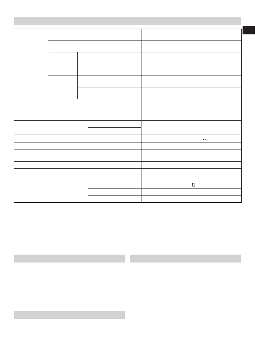
SPECIFICATIONS
English
0°
Miter 45°
Max. Cutting
Capacity
Height × Width
Saw Blade Dimensions (oD × iD × Thickness) 216 mm × 30 mm × 2 mm
Miter Cutting Angle Right 0° – 57°, Left 0° – 45°
Bevel Cutting Angle Right 0° – 5°, Left 0° – 48°
Compound Cutting Angle
Voltage (by areas)*
Power Input* 1050 W
No-Load Speed
Machine Dimensions (Width × Depth × Height) 555 mm × 790 mm × 485 mm
Weight (Net)
Laser Marker
(Only Model C8FSHE / C8FSHE(S))
* Be sure to check the nameplate on product as it is subject to change by areas.
When cutting the workpiece which has the dimension of “**” there might be some possibility of the lower end of the circular
saw to touch with the workpiece, even if the motor head is located at the lower limit position. Pay attention when cutting the
workpiece. For further details, refer to “PRACTICAL APPLICATIONS”. Mount the auxiliary board on the fence surface (Refer
( ) the thickness of auxiliary board). Refer to “10. Cutting large workpieces” (Fig. 20, 21).
1. Minimum size of the workpiece.
All workpieces that can be clamped left or right from the saw blade with the supplied vise assembly.
Model C8FSHE • C8FSHE(S) • C8FSE • C8FSE(S): 245 × 90mm (length × width)
2. Maximum cutting depth.
Model C8FSHE • C8FSHE(S) • C8FSE • C8FSE(S): 65mm (Miter 0° × Bevel 0°)
Bevel
Bevel (Left) 45° + Miter 45°
Compound
Bevel (Right) 5° + Miter 45°
Left 45°
Right 5°
Bevel (Left) 0° – 45°
Bevel (Right) 0° – 5°
Maximum output
(Iambda) 654 nm
Laser medium Laser Diode
**75 mm × 262 mm with aux. board (30 mm)
**75 mm × 185 mm with aux. board (20 mm)
**50 mm × 252 mm with aux. board (30 mm)
**70 mm × 252 mm with aux. board (30 mm)
**50 mm × 170 mm with aux. board (30 mm)
**70 mm × 170 mm with aux. board (30 mm)
C8FSHE(S) • C8FSE(S): 4100 min
65 mm × 312 mm
65 mm × 220 mm
45 mm × 312 mm
60 mm × 312 mm
45 mm × 220 mm
60 mm × 220 mm
Miter (Right and Left) 0° – 45°
(110 V, 230 V)
C8FSHE • C8FSE: 5500 min
14.5 kg (C8FSHE • C8FSHE(S)) /
14 kg (C8FSE • C8FSE(S))
Po<3 mW Class
Laser Product
–1
–1
: with Soft Start
STANDARD ACCESSORIES
○ 216 mm TCT Saw blade (mounted on tool) ...................1
○ Dust bag .......................................................................1
○ 10 mm Box wrench .......................................................1
○ Vise Assembly ..............................................................1
○ Holder ...........................................................................1
○ Side Handle ..................................................................1
○ Sub Fence (mounted on tool) ........................................1
Standard accessories are subject to change without notice.
APPLICATION
Cutting various types of aluminium sash and wood.
PRIOR TO OPERATION
CAUTION
Make all necessary adjustments before inserting the
plug in the power source.
1. Power source
Ensure that the power source to be utilized conforms
to the power requirements specifi ed on the product
nameplate.
Do not use with direct current, or transformers such as
boosters. Doing so may result in damage or accidents.
2. Power switch
Ensure that the power switch is in the OFF position. If the
plug is connected to a receptacle while the trigger switch
is in the ON position, the power tool will start operating
immediately, inviting serious accident.
3. Extention cord
When the work area is removed from the power source,
use an extension cord of suffi cient thickness and rated
capacity. The extension cord should be kept as short as
practicable.
19
Page 20

English
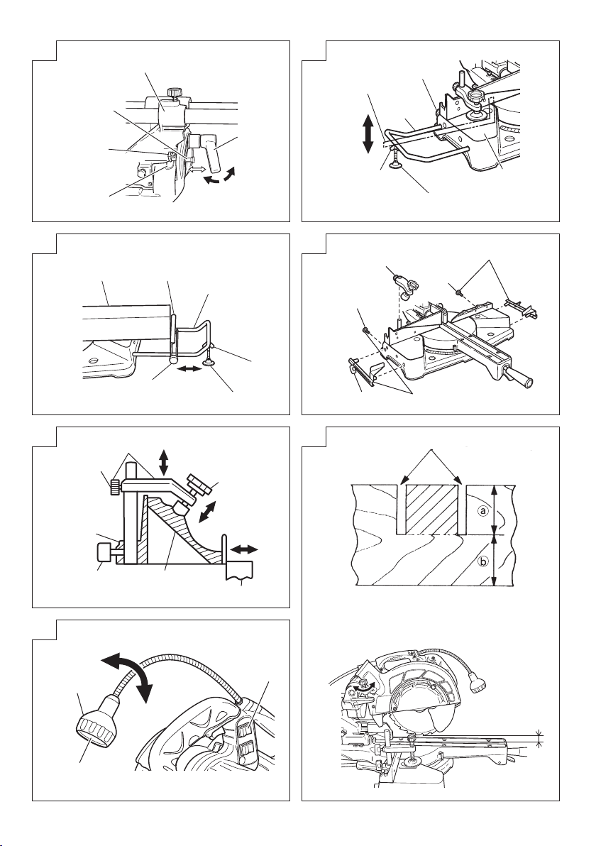
4. Releasing the locking pin (Fig. 3)
When the power tool is prepared for shipping, its main
parts are secured by a locking pin.
Move the handle slightly so that the locking pin can be
disengaged.
During transport, lock the locking pin into the gear case.
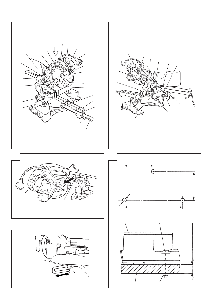
5. Attach the dust bag to the main unit (Fig. 1)
6. Installation (Fig. 4)
Ensure that the machine is always fi xed to bench.
Attach the power tool to a level, horizontal work bench.
Select 8 mm diameter bolts suitable in length for the
thickness of the work bench.
Bolt length should be at least 25 mm plus the thickness
of the work bench.
For example, use 8 mm × 65 mm bolts for a 25 mm thick
work bench.
7. Base holder adjustment (Fig. 5)
Loosen the 6 mm bolt with the supplied 10 mm box
wrench. Adjust the base holder until its bottom surface
contacts the bench or the fl oor surface.
After adjustment, fi rmly tighten the 6 mm bolt.
8. Check to see that the lower guard operates
smoothly
CAUTION
○ This slide compound miter saw is equipped with a saw
head lock as safety device.
○ To lower the saw head to cut, the lock must be released
by pressing the lock lever with your thumb.
(1) When you push down the handle while pushing the lock
lever, check that the lower guard revolves smoothly
(Fig. 6).
(2) Next, check that the lower guard returns to the original
position when the handle is raised.
9. Oblique angle
Before the power tool is shipped from the factory, it is
adjusted for 0°, right angle, left 45° bevel cutting angle
with the 8 mm bolt (A) and 8 mm bolt (B).
When changing the adjustment, change the height of the
8 mm bolt (A) or 8 mm bolt (B) by turning them.
When changing the bevel angle to the left 45° and over,
pull the set pin on the direction shown in Fig. 7-a and
incline the motor head to the left.
When changing the bevel angle to the right, pull the set
pin on the direction shown in Fig. 7-a and incline the
motor head to the right.
When adjusting the motor head to 0°, always return the set
pin to its initial position as shown in
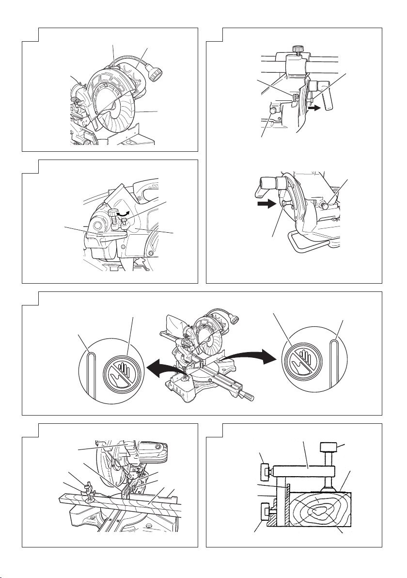
10. Checking the saw blade lower limit position
Check that the saw blade can be lowered 10 mm to 11
mm below the table insert.
When you replace a saw blade with a new one, adjust
the lower limit position so that the saw blade will not cut
the turntable or complete cutting cannot be done.
To adjust the lower limit position of the saw blade, follow
the procedure (1) indicated below. (Fig. 8)
Furthermore, when changing the position of a 8 mm
depth adjustment bolt that serves as a lower limit position
stopper of the saw blade.
(1) Turn the 8 mm depth adjustment bolt, change the height
where the bolt head and the hinge contacts, and adjust
the lower limit position of the saw blade.
NOTE
Confi rm that the saw blade is adjusted so that it will not
cut into the turntable.
Fig. 7-b
.
PRIOR TO CUTTING
1. Cutting a groove on the guard
Holder (A) has a guard (see Fig. 10) into which a groove
must be cut when using the tool for the fi rst time. Loosen
the 6 mm knob bolt to retract the guard slightly.
After placing a suitable wooden piece to sit on the
fence and the table surfaces, fi x it with the vise. Slide
the motor head backwards to the end. Then tighten the
slide securing knob. After the switch has been turned on
and the saw blade has reached maximum speed, slowly
lower the handle to cut a groove on the guard. (See
Fig. 19)
CAUTION
Do not cut the groove too quickly; otherwise the guard
might become damaged.
Do not use slide cutting for grooving tasks.
PRACTICAL APPLICATIONS
WARNING
○ To avoid personal injury, never remove or place a
workpiece on the table while the tool is being operated.
○ Never place your limbs inside of the line next to warning
sign while the tool is being operated (see Fig. 9). This
may cause hazardous conditions.
CAUTION
○ It is dangerous to remove or install the workpiece while
the saw blade is turning.
○ When sawing, clean off the shavings from the turntable.
○ If the shavings accumulate too much, the saw blade from
the cutting material will be exposed. Never subject your
hand or anything else to go near the exposed blade.
1. Switch operation
Pulling the trigger turns the switch on. Releasing the
trigger turns the switch off .
2. Using the Vise Assembly (Standard accessory)
(Fig. 11)
(1) The vise assembly can be mounted on either the left
fence {Fence (B)} or the right fence {Fence (A)} by
loosening the 6 mm wing bolt (A).
(2) The screw holder can be raised or lowered according to
the height of the workpiece by loosening the 6 mm wing
bolt (B). After the adjustment, fi rmly tighten the 6 mm
wing bolt (B) and fi x the screw holder.
(3) Turn the upper knob and securely fi x the workpiece in
position.
WARNING
Always fi rmly clamp or vise to secure the workpiece to
the fence; otherwise the workpiece might be thrust from
the table and cause bodily harm.
CAUTION
Always confi rm that the motor head does not contact the
vise assembly when it is lowered for cutting. If there is
any danger that it may do so, loosen the 6 mm wing bolt
and move the vise assembly to a position where it will not
contact the saw blade.
3. Positioning the table insert (Fig. 12)
Table inserts are installed on the turntable. When
shipping the tool from the factory, the table inserts are
so fi xed that the saw blade does not contact them. The
burr of the bottom surface of the workpiece is remarkably
reduced, if the table insert is fi xed so that the gap
between the side surface of the table insert and the saw
blade will be minimum. Before using the tool, eliminate
this gap in accordance with the following procedure.
(1) Right angle cutting
Loosen the three 6 mm machine screws, then secure
the left side table insert and temporarily tighten the 6
mm machine screws of both ends. Then fi x a workpiece
(about 200 mm wide) with the vise assembly and cut it
off . After aligning the cutting surface with the edge of the
table insert, securely tighten the 6 mm machine screws
of both ends. Remove the workpiece and securely
tighten the 6 mm center machine screw. Adjust the right
hand table insert in the same way.
(2) Left and right bevel angle cutting
Adjust the table insert in the manner same procedure for
right angle cutting.
20
Page 21

English
CAUTION
After adjusting the table insert for right angle cutting, the
table insert will be cut to some extent if it is used for bevel
angle cutting.
When bevel cutting operation is required, adjust the
table insert for bevel angle cutting.
4. Confi rmation for use of sub fence (Fig. 13)
This slide compound miter saw is equipped with a sub
fence. In the case of direct angle cutting and right bevel
angle cutting, use the sub fence. Then, you can do Left
bevel angle cutting, Right bevel angle cutting and Direct
angle cutting and realize stable cutting of the material
with a wide back face.
WARNING
In the case of left bevel cutting, turn the sub fence
counterclockwise (Fig. 13). Unless it is turned
counterclockwise, the main body or saw blade may
contact the sub fence, resulting in an injury.
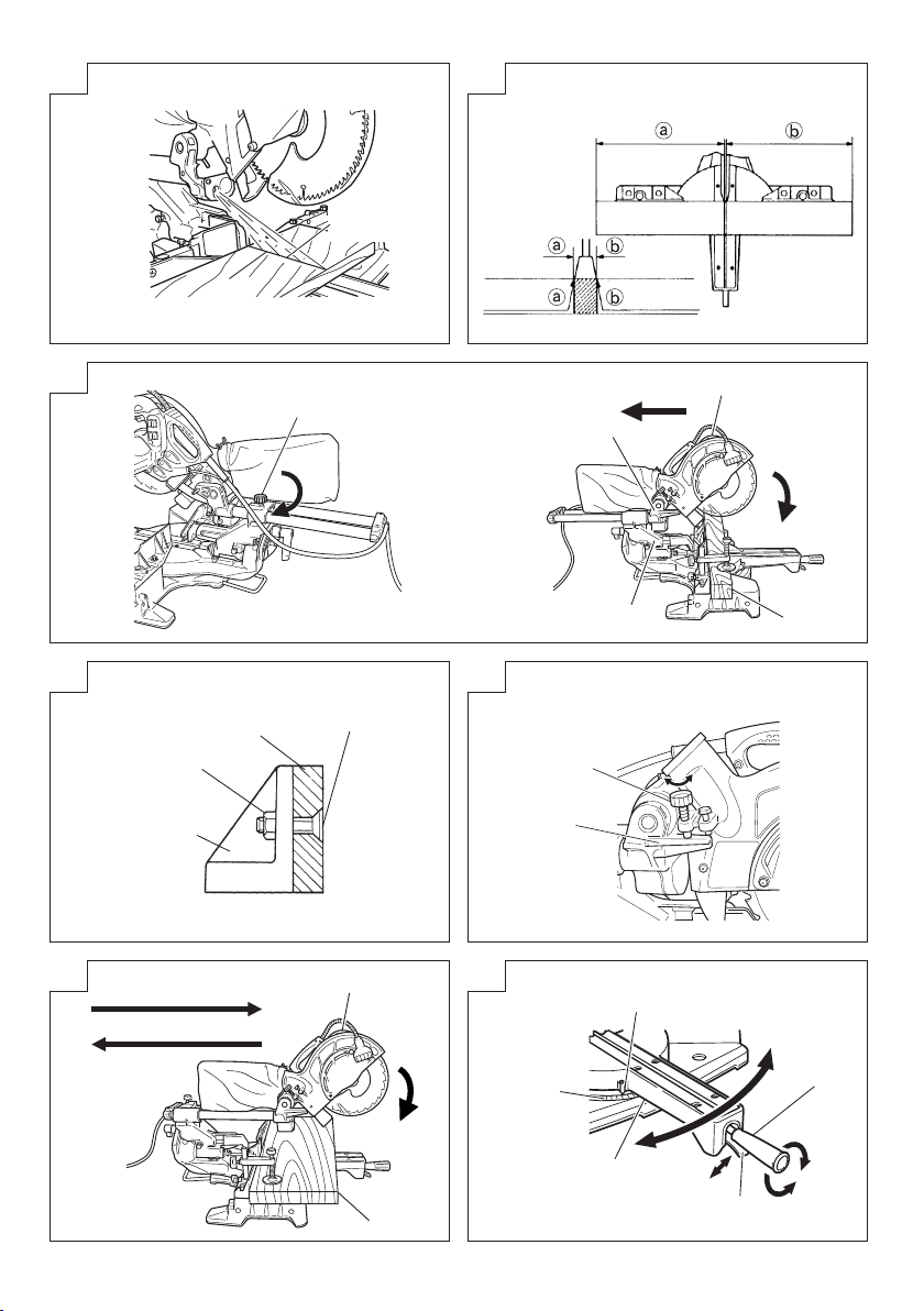
5. Using an ink line (Adjusting the guard)
(1) Right angle cutting
Loosen the 6 mm knob bolt and contact the tip of the
guard with the workpiece.
Aligning the ink line on the workpiece with the groove of
the guard, the workpiece is cut on the ink line.
(2) Miter cutting and compound cutting (Miter cutting +
bevel cutting)
Upon lowering the motor section, the lower guard is
raised and the saw blade appears.
Align the ink line with the saw blade.
CAUTION
In some arrangements when the turntable is rotated, the
guard projects from the fence surface. Loosen the 6 mm
knob bolt and push the guard to the retracted position.
Never lift the lower guard while the saw blade is rotating.
When cutting at an angle of 45° to the right or more,
please slide the guard to the rear.
The guard and sub-fence will not only make contact and
adversely aff ect cutting accuracy, this could also result in
damage to the guard.
6. Install the side handle (Fig. 1)
Install the side handle that came enclosed with this unit.
7. Position adjustment of laser line (Only Model
C8FSHE / C8FSHE(S))
Ink lining can be easily made on this tool to the laser
marker. A switch lights up the laser marker (Fig. 14).
Depending upon your cutting choice, the laser line can
be aligned with the left side of the cutting width (saw
blade) or the ink line on the right side.
The laser line is adjusted to the width of the saw blade at
the time of factory shipment. Adjust the positions of the
saw blade and the laser line taking the following steps to
suit the use of your choice.
(1) Light up the laser marker and make a groove of about 5
mm deep on the workpiece that is about 20 mm in height
and 150 mm in width. Hold the grooved workpiece by
vise as it is and do not move it. For grooving work, refer
to “19. Groove cutting procedures”.
(2) Then, turn the adjuster and shift the laser line. (If you turn
the adjuster clockwise, the laser line will shift to the right
and if you turn it counterclockwise, the laser line will shift
to the left.) When you work with the ink line aligned with
the left side of the saw blade, align the laser line with the
left end of the groove (Fig. 15). When you align it with
the right side of the saw blade, align the laser line with
the right side of the groove.
(3) After adjusting the position of the laser line, draw a right-
angle ink line on the workpiece and align the ink line
with the laser line. When aligning the ink line, slide the
workpiece little by little and secure it by vise at a position
where the laser line overlaps with the ink line. Work on
the grooving again and check the position of the laser
line. If you wish to change the laser line’s position, make
adjustments again following the steps from (1) to (3).
WARNING
○ Make sure before plugging the power plug into the
receptacle that the main body and the laser marker are
turned off .
○ Exercise utmost caution in handling a switch trigger for
the position adjustment of the laser line, as the power
plug is plugged into the receptacle during operation.
If the switch trigger is pulled inadvertently, the saw blade
can rotate and result in unexpected accidents.
○ Do not remove the laser marker to be used for other
purposes.
CAUTION (Fig. 16)
○ Laser radiation - Do not stare into beam.
○ Laser radiation on work table. Do not stare into beam. If
your eye is exposed directly to the laser beam, it can be
hurt.
○ Do not dismantle it.
○ Do not give strong impact to the laser marker (main body
of tool); otherwise, the position of a laser line can go out
of order, resulting in the damage of the laser marker as
well as a shortened service life.
○ Keep the laser marker lit only during a cutting operation.
Prolonged lighting of the laser marker can result in a
shortened service life.
○ Use of controls or adjustments or performance of
procedures other than those specifi ed herein may result
in hazardous radiation exposure.
NOTE
○ Perform cutting by overlapping the ink line with the laser
line.
○ When the ink line and the laser line are overlapped, the
strength and weakness of light will change, resulting in a
stable cutting operation because you can easily discern
the conformity of lines. This ensures the minimum cutting
errors.
○ In outdoor or near-the-window operations, it may
become diffi cult to observe the laser line due to the
sunlight. Under such circumstances, move to a place
that is not directly under the sunlight and engage in the
operation.
○ Check and make sure on a periodic basis if the position
of the laser line is in order. As regards the checking
method, draw a right-angle ink line on the workpiece with
the height of about 20 mm and the width of 150 mm, and
check that the laser line is in line with the ink line [The
deviation between the ink line and the laser line should
be less than the ink line width (0.5 mm)]. (Fig. 17)
8. Cutting operation
(1) As shown in Fig. 18
width of the cut. Therefore, slide the workpiece to the
right (viewed from the operator’s position) when length
is desired, or to the left when length is desired.
If a laser marker is used, align the laser line with the left
side of the saw blade, and then align the ink line with the
laser line.
(2) After turning on the switch and checking that the saw
blade is rotating at maximum speed, slowly push down
the handle while holding down the lock lever and bring
the saw blade in the vicinity of the material to be cut.
(3) Once the saw blade contacts the workpiece, push the
handle down gradually to cut into the workpiece.
(4) After cutting the workpiece to the desired depth, turn the
power tool OFF and let the saw blade stop completely
before raising the handle from the workpiece to return it
to the full retract position.
CAUTION
○ For maximum dimensions for cutting, refer to
“SPECIFICATIONS” table.
○ Increased pressure on the handle will not increase the
cutting speed. On the contrary, too much pressure may
result in overload of the motor and/or decreased cutting
effi ciency.
21
the width of the saw blade is the
Page 22

English
○ Confi rm that the trigger switch is turned OFF and the
power plug has been removed from the receptacle
whenever the tool is not in use.
○ Always turn the power off and let the saw blade stop
completely before raising the handle from the workpiece.
If the handle is raised while the saw blade is still rotating,
the cut-off piece may become jammed against the saw
blade causing fragments to scatter about dangerously.
○ Every time one cutting of deep-cutting operation is
fi nished, turn the switch off , and check that the saw
blade has stopped. Then raise the handle, and return it
to the full retract position.
○ Be absolutely sure to remove the cut material from the
top of the turntable, and then proceed to the next step.
9. Cutting narrow workpieces (Press cutting) (Fig. 19)
Slide the hinge down to holder (A), then tighten the
slide securing knob (Fig. 2). Lower the handle to cut
the workpiece. Using the power tool this way will permit
cutting of workpieces of up to 65 mm square.
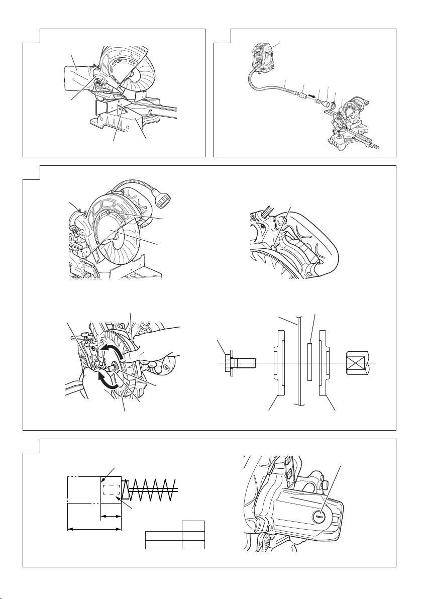
10. Cutting large workpieces (Fig. 20, 21)
There may be case when a complete cutting cannot be
done depending on the height of workpiece. In this case,
mount an auxiliary board with the 6 mm fl at head screws
and the 6 mm nuts using the 7 mm holes on the fence
surface (two holes on each side). (Fig. 20)
Refer to “SPECIFICATIONS” for the thickness of the
auxiliary board.
NOTE
When cutting a workpiece exceeding 65 mm in height in
right-angle cutting or 60 mm in left bevel angle cutting or
45 mm in right bevel angle cutting, adjust the lower limit
position so that the base of the motor head will not come
in contact with the workpiece.
To adjust the lower limit position of the saw blade, follow the
procedure (1) shown in Fig. 21.
(1) Lower the motor head, and turn the 6 mm depth
adjustment bolt and make adjustments so that there can
be a clearance of 2 mm to 3 mm between the lower limit
position of the motor head and the top of the workpiece
at the saw blade's lower limit position where the head of
the 6 mm depth adjustment bolt contacts the hinge.
11. Cutting wide workpieces (Slide cutting) (Fig. 22)
Loosen the slide securing knob (Fig. 2), grip the handle
and slide the saw blade forward. Then press down
on the handle and slide the saw blade back to cut the
workpiece. This facilitates cutting of workpieces of up to
312 mm in width.
WARNING
Never put your hand on the side handle during the
cutting operation because the saw blade comes close to
the side handle when the motor head is lowered.
12. Miter cutting procedures
(1) Loosen the side handle and pull up the lever for angle
stoppers. Then, adjust the turntable until the indicator
aligns with desired setting on the miter scale (Fig. 23).
(2) Re-tighten the side handle to secure the turntable in the
desired position.
(3) The miter scale indicates both the cutting angle on the
angle scale and the gradient on the grade scale.
(4) The gradient, which is the ratio of the height to the base
of the triangular section to be removed, may be used
for setting the miter scale instead of the cutting angle, if
desired.
Therefore, to cut a workpiece at a grade of 2/10, set the
indicator to position.
NOTE
○ Positive stops are provided at the right and left of the 0°
center setting, at 15°, 22.5°, 31.6° and 45° settings.
Check that the miter scale and the tip of the indicator are
properly aligned.
○ Operation of the saw with the miter scale and indicator
out of alignment, or with the side handle not properly
tightened, will result in poor cutting precision.
13. Bevel cutting procedures (Fig. 24)
(1) Loosen the clamp lever and bevel the saw blade to the
left or to the right. When tilting the motor head to the right
pull the set pin towards the rear.
NOTE
Loosen the clamp lever, tilt the main unit to the left and
then pull the set pin to enable 48-degree cuts.
Loosen the clamp lever and slant to the left a little at a
time while pushing the set pin into the main unit. At this
time, the set pin will enter one step and fi t into the 30° left
slant and 33.9° left slant setting slots.
With the set pin in the slot as described above, setting
to the 30° left slant position is possible by pushing to the
right side.
Also, with the set pin in the slot as described above,
setting to the 33.9° left slant position is possible by
pushing to the left side.
(2) Adjust the bevel angle to the desired setting
while watching the bevel angle scale and indicator,
then secure the clamp lever.
WARNING
When the workpiece is secured on the left or right side
of the blade, the short cut-off portion will come to rest
on the right or left side of the saw blade. Always turn the
power off and let the saw blade stop completely before
raising the handle from the workpiece.
If the handle is raised while the saw blade is still rotating,
the cut-off piece may become jammed against the saw
blade causing fragments to scatter about dangerously.
When stopping the bevel cutting operation halfway, start
cutting after pulling back the motor head to the initial
position.
Starting from halfway, without pulling back, causes the
lower guard to be caught in the cutting groove of the
workpiece and to contact the saw blade.
14. Compound cutting procedures
Compound cutting can be performed by following the
instructions in 13 and 14 above. For maximum dimensions
for compound cutting, refer to “SPECIFICATIONS” table.
CAUTION
Always secure the workpiece with the right or left
hand and cut it by sliding the round portion of the saw
backwards with the left hand.
It is very dangerous to rotate the turntable to the left
during compound cutting because the saw blade may
come into contact with the hand that is securing the
workpiece.
In case of compound cutting (angle + bevel) by
left bevel, turn the sub-fence (optional accessory)
counterclockwise, and engage in the cutting operation.
15. Cutting long materials
When cutting long materials, use an auxiliary platform
which is the same height as the holder (optional
accessory) and base of the special auxiliary equipment.
Capacity: wooden material (W × H × L)
16. Installing the holders … (Optional accessory)
The holders help keep longer workpieces stable and in
place during the cutting operation.
(1) As indicated in Fig. 25, use a steel square for aligning
the upper edge of the holders with the base surface.
Loosen the 6 mm wing nut. Turn a height adjustment bolt
6 mm, and adjust the height of the holder.
(2) After adjustment, fi rmly tighten the wing nut and fasten
the holder with the 6 mm knob bolt (optional accessory). If
the length of Height Adjustment Bolt 6 mm is insuffi cient,
spread a thin plate beneath. Make sure the end of Height
Adjustment Bolt 6 mm does not protrude from the holder.
22
300 mm × 45 mm × 1050 mm, or
180 mm × 25 mm × 1600 mm
Page 23

English
CAUTION
○ When transporting or carrying the tool, do not grasp the
holder.
○ There is the danger of the holder slipping out of the base.
Grasp the handle instead of the holder.
17. Stopper for precision cutting … (Stopper and
holder are optional accessory)
The stopper facilitates continuous precision cutting in
lengths of 280 mm to 450 mm.
To install the stopper, attach it to the holder with the 6
mm knob bolt as shown in Fig. 26.
18. Confi rmation for use Crown molding vise, Crown
molding Stopper (L) and (R) (Optional accessory)
(1) Crown molding Stopper (L) and (R) (optional
accessories) allow easier cuts of crown molding without
tilting the saw blade. lnstall them in the base both-sides
side to be shown in Fig. 27. After inserting tighten the
6 mm knob bolts to secure the Crown molding Stoppers.
(2) The crown molding vise (B) (Optional accessory) can be
mounted on either the left fence (Fence (B)) or the right
fence (Fence (A)). lt can unite with the slope of the crown
molding and vice can be pressed down.
Then turn the upper knob, as necessary, to securely
attach the crown molding in position. To raise or lower
the vise assembly, fi rst loosen the 6 mm knob bolt.
After adjusting the height, fi rmly tighten the 6 mm wing
bolt; then turn the upper knob, as necessary, to securely
attach the the crown molding in position (Fig. 28).
Position crown molding with its WALL CONTACT EDGE
against the guide fence and its CEILING CONTACT
EDGE against the Crown molding Stoppers as shown in
Fig. 28. Adjust the Crown molding Stoppers according
to the size of the crown molding.
Tighten the 6 mm wing bolt to secure the Crown molding
Stoppers.
WARNING
Always fi rmly clamp or vise to secure the crown molding
to the fence; otherwise the crown molding might be
thrust from the table and cause bodily harm.
Do not bevel cutting. The main body or saw blade may
contact the sub fence, resulting in an injury.
CAUTION
Always confi rm that the motor head does not contact the
crown molding vise ass’y when it is lowered for cutting.
If there is any danger that it may do so, loosen the 6 mm
knob bolt and move the crown molding vise ass’y to a
position where it will not contact the saw blade.
19. Groove cutting procedures
Grooves in the workpiece can be cut by adjusting the
6 mm depth adjustment bolt (Fig. 29).
(1) Lower the motor head, and turn the 6 mm depth
adjustment bolt by hand. (Where the head of the 6 mm
depth adjustment bolt contacts the hinge.)
(2) Adjust to the desired cutting depth by setting the
distance between the saw blade and the surface of the
base. (Fig. 29)
NOTE
When cutting a single groove at either end of the
workpiece, remove the unneeded portion with a chisel.
20. Using the Light (Only Model C8FSHE / C8FSHE(S))
WARNING
○ Check to ascertain that the main unit and light are off
before plugging the cord into the power socket.
○ The light lens reaches high temperatures during and
immediately after use and should not be touched under
any circumstances.
Failure to observe this may result in burns.
CAUTION
○ Do not subject the light to strong impact.
Failure to observe this may result in damage to the light
or a reduced life span.
○ Only switch the light on when cutting.
○ Do not shine the light continuously into the eyes.
Failure to observe this may result in damage to the eyes.
○ Wipe all dirt that adheres to the light lens with a soft cloth
gently so that the light is not scratched or damaged.
Scratches on the light lens may result in less luminance.
○ The light switch is fi tted with an anti-dust cover. Make
sure that the switch cover is not scratched or otherwise
damaged.
○ There are cases in which shavings may enter the switch
and prevent the light from functioning.
(1) Insert the plug on the main unit into a power socket.
(2) Set the light switch into the upper position (ON) to light
it, and into the lower position (OFF) to switch it off . (See
Fig. 30)
(3) Move the light fi tting to the right and left to adjust the
lighting position.
21. Using the dust bag (Standard accessory) (Fig. 31)
(1) Connect the dust bag with the duct of power tool.
(2) When the dust bag has become full of sawdust, dust will
be blown out of the dust bag when the saw blade rotates.
Check the dust bag periodically and empty it before it
becomes full.
(3) During bevel and compound cutting, attach the dust bag
at the right angle to the base surface.
22. Connecting the dust extractor (Sold separately)
(Fig. 32)
Do not inhale the harmful dusts generated in cutting
operation.
The dust can endanger the health of yourself and
bystanders.
Use of dust extractor can reduce dust related hazards.
By connecting with dust extractor through adapter,
joint and dust collection adapter, most of dust can be
collected.
Connect the dust extractor with adapter.
(1) Connect in order of hose (id 38 mm × 3 m long) and
adapter (Dust extractor’s Standard accessory) joint
(Optional accessory) and dust collection adapter
(Optional accessory) with the duct of power tool.
Connection is done by pressing in the direction of the
arrow. (Fig. 32)
The dust collection adapter (Optional accessory) is fi xed
to the duct by a hose band. (Optional accessory)
MOUNTING AND DISMOUNTING SAW
BLADE
WARNING
To prevent an accident or personal injury, always turn off
the trigger switch and disconnect the power plug from
the receptacle before removing or installing a blade.
1. Mounting the saw blade (Fig. 33)
(1) Use the accessory 10 mm box wrench to loosen the 6
mm bolt fastening the spindle cover and then rotate the
spindle cover.
(2) Press in spindle lock and loosen bolt with 10 mm box
wrench.
Since the bolt is left-hand threaded, loosen by turning it
to the right.
NOTE
If the spindle lock cannot be easily pressed in to lock
the spindle, turn the bolt with 10 mm box wrench while
applying pressure on the spindle lock.
The saw blade spindle is locked when the spindle lock is
pressed inward.
(3) Remove the bolt and washer (D).
(4) Lift the lower guard and mount the saw blade.
WARNING
When mounting the saw blade, confi rm that the rotation
indicator mark on the saw blade and the rotation direction
of the gear case are properly matched.
23
Page 24

English
(5) Thoroughly clean washer (D) and the bolt, and install
them onto the saw blade spindle.
(6) Press in the spindle lock and tighten the bolt by turning it
to the left by 10 mm box wrench.
(7) Rotate the spindle cover unitl hook in spindle cover is in
the original position. Then tighten the 6 mm bolt.
CAUTION
○ Confi rm that the spindle lock has returned to the retract
position after installing or removing the saw blade.
○ Tighten the bolt so it does not come loose during
operation.
○ Confi rm that the bolt has been properly tightened before
the power tool is started.
○ Confi rm that the lower guard has closed position.
2. Dismounting the saw blade
Dismount the saw blade by reversing the mounting
procedures described in paragraph 1 above.
The saw blade can easily be removed after lifting the
lower guard.
CAUTION
Never attempt to install saw blades except
216 mm in diameter.
MAINTENANCE AND INSPECTION
WARNING
To avoid an accident or personal injury, always confi rm
the trigger switch is turned OFF and that the power
plug has been disconnected from the receptacle before
performing any maintenance or inspection of this tool.
Report to qualifi ed person as soon as possible, if you
discover the fault of machine including guards or blade
saw.
1. Inspecting the saw blade
Always replace the saw blade immediately upon the fi rst
sign of deterioration or damage.
A damaged saw blade can cause personal injury and
a worn saw blade can cause ineff ective operation and
possible overload to the motor.
CAUTION
Never use a dull saw blade. When a saw blade is dull,
its resistance to the hand pressure applied by the tool
handle tends to increase, making it unsafe to operate the
power tool.
2. Inspecting the mounting screws
Regularly inspect all mounting screws and ensure that
they are properly tightened. Should any of the screws
be loose, re-tighten them immediately. Failure to do so
could result in serious hazard.
3. Inspecting the carbon brushes (Fig. 34)
The motor employs carbon brushes which are
consumable parts. Since an excessively worn carbon
brush can result in motor trouble, replace the carbon
brushes with new ones having the same carbon brush
No. shown in the fi gure when it becomes worn to or near
the “wear limit”. In addition, always keep carbon brushes
clean and ensure that they slide freely within the brush
holders.
4. Replacing a carbon brushes (Fig. 34)
Disassemble the brush cap with a slotted-head
screwdriver. The carbon brushes can then be easily
removed.
5. Maintenance of the motor
The motor unit winding is the very “heart” of the power
tool. Exercise due care to ensure the winding does not
become damaged and/or wet with oil or water.
6. Inspecting the lower guard for proper operation
Before each use of the tool, test the lower guard (Fig.
6) to assure that it is in good condition and that it moves
smoothly.
Never use the tool unless the lower guard operates
properly and it is in good mechanical condition.
24
7. Storage
After operation of the tool has been completed, check
that the following has been performed:
(1) Trigger switch is in OFF position,
(2) Power plug has been removed from the receptacle,
When the tool is not in use, keep it stored in a dry place
out of the reach of children.
8. Lubrication
Lubricate the following sliding surfaces once a month
to keep the power tool in good operating condition for a
long time.
Use of machine oil is recommended.
Oil supply points:
* Rotary portion of hinge
* Rotary portion of holder (A)
* Rotary portion of vise assembly
9. Cleaning
Periodically remove chips and other waste material
from the surface of the power tool with a damp, soapy
cloth. To avoid a malfunction of the motor, protect it from
contact with oil or water.
(Only Model C8FSHE / C8FSHE(S))
If the laser line becomes invisible due to chips and the
like adhered onto the window of the laser marker's light-
emitting section, wipe and clean the window with a dry
cloth or a soft cloth moistened with soapy water, etc.
SELECTING ACCESSORIES
The accessories of this machine are listed on page 141.
CAUTION
Repair, modifi cation and inspection of Hitachi Power
Tools must be carried out by a Hitachi Authorized
Service Center.
Especially laser or LED device should be maintained by
the authorized agent by laser or LED manufacturer.
Always assign the repair of laser or LED device to Hitach
Authorized Service Center.
In the operation and maintenance of power tools, the
safety regulations and standards prescribed in each
country must be observed.
GUARANTEE
We guarantee Hitachi Power Tools in accordance with
statutory/country specifi c regulation. This guarantee does
not cover defects or damage due to misuse, abuse, or
normal wear and tear. In case of complaint, please send
the Power Tool, undismantled, with the GUARANTEE
CERTIFICATE found at the end of this Handling instruction,
to a Hitachi Authorized Service Center.
NOTE
Due to HITACHI’s continuing program of research and
development the specifi cations herein are subject to change
without prior notice.
Page 25

Information concerning airborne noise and vibration
The measured values were determined according to
EN61029 and declared in accordance with ISO 4871.
Measured A-weighted sound power level: 105 dB (A).
Measured A-weighted sound pressure level: 96 dB (A).
Uncertainty K: 3 dB (A).
Wear hearing protection.
Vibration total values (triax vector sum) determined
according to EN61029.
Cutting wood:
Vibration emission value a
Uncertainty K = 1.5 m/s
The declared vibration total value has been measured in
accordance with a standard test method and may be used
for comparing one tool with another.
It may also be used in a preliminary assessment of exposure.
WARNING
○ The vibration emission during actual use of the power
tool can diff er from the declared total value depending in
the ways in which the tool is used.
○ Identify safety measures to protect the operator that
are based on an estimation of exposure in the actual
conditions of use (taking account of all parts of the
operating cycle such as the times when the tool is
switched off and when it is running idle in addition to the
trigger time).
Information for power supply system to be used with
electric tools provided with rated voltage 230 V~
Switching operations of electric apparatus cause voltage
fl uctuations.
The operation of this electric tool under unfavorable mains
conditions can have adverse eff ects to the operation of other
electric apparatus.
With a mains impedance equal or less than 0.29 Ohms there
will probably be no negative eff ects.
Usually, the maximum permissible mains impedance will
not be exceeded when the branch to the power outlet is fed
from a junction box with a service capacity of 25 ampere or
higher.
In case of power failure, or when the power plug is pulled
out, immediately return the switch to OFF position. This
prevents an uncontrolled restart.
2
= 1.3 m/s
h
2
English
25
Page 26

Deutsch
(Übersetzung der Original-Gebrauchsanweisung)
ALLGEMEINE
VORSICHTSMASSNAHMEN
WARNUNG! Bei der Verwendung von Elektrowerkzeugen
müssen immer die grundlegenden Vorsichtsmaßnahmen
befolgt werden, um das Risiko von Feuer, elektrischem
Schlag und persönlicher Verletzung und den nachfolgenden
Punkten zu vermeiden.
Lesen Sie diese Anweisungen völlig, bevor Sie dieses Erzeugnis
verwenden, und bewahren Sie diese Anweisungen auf.
Für sicheren Betrieb:
1. Der Arbeitsplatz sollte sauber gehalten werden.
Unaufgeräumte Arbeitsplätze und Werkbänke erhöhen
die Unfallgefahr.
2. Die Betriebsbedingungen beachten. Elektrowerkzeuge
sollten nicht dem Regen ausgesetzt werden. Ebenfalls
sollten Sie nicht an feuchten oder nassen Plätzen
gebraucht werden. Der Arbeitsplatz sollte gut beleuchtet
sein.
Verwenden Sie Elektrowerkzeuge nicht an Orten, an
denen die Gefahr von Feuer oder Explosion besteht.
3. Schutzmaß nahmen gegen elektrische Schläge treff en.
Darauf achten, daß das Gehäuse nicht in Kontakt mit
geerdeten Flachen kommt (z.B. Rohre, Radiatoren,
Elektroherde, Kühlschränke).
4. Kinder und gebrechliche Personen sollten vom Gerät
ferngehalten werden. Andere Personen nicht mit dem
Werkzeug oder dem Verlängerungskabel in Kontakt
kommen lassen. Besucher sollten vom Arbeitsbereich
ferngehalten werden.
5. Nicht benutzte Werkzeuge sollten sicher aufbewahrt
werden. Sie sollten an einem trockenen und
hochgelegenen oder verschließbaren Ort aufbewahrt
werden, außerhalb der Reichweite von Kindern und
gebrechlichen Personen.
6. Werkzeuge sollten nicht mit übermäßiger Gewalt
verwendet werden. Ihre Leistung ist besser und sicherer,
wenn sie mit der vorgeschriebenen Geschwindigkeit
verwendet werden.
7. Nur die korrekten Werkzeuge verwenden. Niemals
ein kleineres Werkzeug oder Zusatzgerat für Arbeiten
verwenden, die Hochleistungsgerate erfordern. Nur
Werkzeuge verwenden, die dem Verwendungszweck
entsprechen, d.h. niemals eine Kreissäge zum Sägen
von Ästen oder Baum-stämmen verwenden.
8. Die richtige Kleidung tragen. Keine lose Kleidung oder
Schmuck tragen, da sich lose Kleidungsstücke in den
bewegenden Teilen verfangen können. Bei Arbeiten
im Freien sollten Gummihandschuhe und rutschfeste
Schuhe getragen werden. Tragen Sie eine schützende
Haarabdeckung, um langes Haar zurückzuhalten.
9. Es sollte eine Sicherheitsbrille getragen werden. Bei
Arbeiten mit Staubentwicklung sollte eine Gesichtsoder
Staubmaske getragen werden.
10. Schließen Sie eine Staubabsaugvorrichtung an.
Sägen mit dieser Verbundsäge kann eine beträchtliche
Menge Staub aus dem Auslass am fi xierten Schutz
verursachen.
(Staubmaterial: Holz oder Aluminium)
Wenn Vorrichtungen für den Anschluß von Staubabsaug-
und -sammelvorrichtungen vorhanden sind, so stellen
Sie sicher, daß diese angeschlossen sind und richtig
verwendet werden.
11. Niemals das Kabel mißbrauchen. Ein Werkzeug niemals
am Kabel tragen oder bei Abtrennung von der Steckdose
das Kabel harausreißen. Das Kabel sollte gegen Hitze,
Öl und scharfe Kanten geschützt werden.
12. Den Arbeitsplatz gut absichern. Zwingen oder einen
Schraubstock zur Befestigung des Werkstücks
verwenden. Das ist sicherer als die Benutzung der
Hände und macht beide Hände zur Bedienung des
Werkzeugs frei.
13. Sich niemals weit überbeugen. Immer einen festen
Stand und ein sicheres Gleichgewicht bewahren.
14. Die Werkzeuge sollten sorgfältig behandelt werden.
Für einen einwandfreien und sicheren Betrieb sollten
sie stets scharf sein und saubergehalten werden.
Die Anleitungen für schmierung und Austausch des
Zuehörs unbedingt einhalten. Die Kabel der Geräte
regelmäßig überprüfen und bei Beschädigung durch
eine autorisierte Kundendienststelle reparieren lassen.
Ebenfalls die Verlägerungskabel regelmäßig überprüfen
und bei Beschadigung auswechseln. Die Handgriff e
sollten stets trocken und sauber sein, sowie keine Öloder Schmierfett stellen aufweisen.
15. Werkzeuge vom Netz trennen, wenn sie nicht benutzt
werden, vor Wartungsarbeiten und beim Austausch von
Zubehörteilen wie z.B. Blätter, Bohrer und Messer.
16. Alle Stellkeile und Schraubenschlüssel entfernen. Vor
Einschaltung des Gerätes darauf achten, daß alle
Stellkeile und Schraubenschlüssel entfernt worden sind.
17. Ein unbeabsichtigtes Einschalten sollte vermieden
werden. Niemals ein angeschlossenes Werkzeug
mit dem Finger am Schalter tragen. Vor Anschluß
überprüfen, ob das Gerät ausgeschaltet ist.
18. Im Freien ein Verlängerungskabel verwenden. Nur ein
Verlängerungskabel verwenden, das für die Verwendung
im Freien markiert ist.
19. Den Arbeitsvorgang immer unter Kontrolle haben.
Das Gerät niemals in einem abgespannten Zustand
verwenden.
20. Beschädigte Teile überprüfen. Vor Benutzung
des Werkzeugs sollten beschädigte Teile oder
Schutzvorrichtungen sorgfältig überprüft werden,
um festzustellen, ob sie einwandfrei funktionieren
und die vorgesehene Funktion erfüllen, Ausrichtung,
Verbindungen sowie Anbringung sich bewegender Teile
überprüfen. Ebenfalls uberprufen, ob Teile gebrochen
sind. Teile oder Schutzvorrichtungen, die beschädigt
sind, sollten, wenn in dieser Bedienungsanleitung
nichts anderes erwähnt ist, durch eine autorisierte
Kundendienststelle ausge wechselt oder repariert
werden. Dasselbe gilt für defekte Schalter. Wenn sich das
Werkzeug nicht mit dem Schalter einoder ausschalten
läßt, sollte das Werkzeug nicht verwendet werden.
21. Warnung
Die Verwendung von anderem Zubehör oder anderen
Zusätzen als in dieser Bedienungs-anleitung empfohlen
kann das Risiko einer Körperverletzung einschließen.
22. Lassen Sie Ihr Werkzeug durch qualifi ziertes Personal
reparieren.
Dieses Elektrowerkzeug entspricht den zutreff enden
Sicherheitsanforderungen. Reparaturen sollten nur
von qualifi ziertem Personal unter Verwendung von
Originalersatzteilen durchgeführt werden, da sonst
beträchtliche Gefahr für den Benutzer auftreten kann.
VORSICHTSHINWEISE ZUR
VERWENDUNG DER PANEELSÄGE
1. Halten Sie den Boden um die Maschine herum eben, gut
gewartet und frei von losem Material wie z.B. Sägespäne
und abgesägten Stücken.
2. Sorgen Sie für ausreichende allgemeine und örtliche
Beleuchtung.
3. Elektrowerkzeuge nur für die in der Bedienungsanleitung angeführten Anwendungen verwenden.
4. Reparaturen dürfen nur durch autorisierte
Wartungseinrichtungen durchgeführt werden. Der
Hersteller ist nicht verantwortlich für Beschädigungen
oder Verletzungen, die durch Reparatur durch nicht
autorisierte Personen oder durch Mißbrauch des
Werkzeugs verursacht werden.
26
Page 27

Deutsch
5. Zur Sicherstellung der Betriebsintegrität von
Elektrowerkzeugen niemals installierte Abdeckungen
oder Schrauben entfernen.
6. Bewegliche Teile und Zubehör nur berühren, wenn das
Werkzeug nicht an die Stromversorgung angeschlossen
ist.
7. Das Werkzeug mit einer geringeren Leistungs-aufnahme
als auf dem Typenschild angezeigt verwenden, da
sonst durch Überlastung die Qualität der bearbeiteten
Oberfl äche bzw. der Wirkungsgrad beeinträchtigt
werden kann.
8. Plastikteile nicht mit Lösungsmittel abwischen.
Lösungsmittel wie Benzin, Verdünner,
Kohlenstoff tetrachlorid oder Alkohol können
Plastikmaterial beschädigen oder Risse verursachen.
Nie mit Lösungsmittel abwischen. Plastikteile mit einem
mit Seifenwasser angefeuchteten weichen Lappen
reinigen.
9. Nur Originalersatzteile von HITACHI verwenden.
10. Dieses Werkzeug sollte nur zum Auswechseln der
Kohlebürsten zerlegt werden.
11.
Die Explosionszeichnung in dieser Bedienungsanleitung ist
nur für autorisierte Wartungseinrichtungen gedacht.
12. Sägen Sie niemals Metall oder Mauerwerk.
13. Ausreichende allgemeine oder lokalisierte Beleuchtung
ist vorgesehen. Vorrat und fertige Werkstücke befi nden
sich in der Nähe der normalen Arbeitsposition der
Bedienung.
14.
Tragen Sie ausreichende persönliche Schutzausrüstung,
wenn erforderlich. Dies kann z.B. einschließen:
Gehörschutz zur Verringerung des Risikos von
induziertem Gehörverlust.
Augenschutz zur Verringerung des Risikos von
Augenverletzungen.
Atemschutz zur Verringerung des Risikos von Einatmen
von schädlichem Staub.
Handschuhe zur Handhabung von Sägeblättern
(Sägeblätter sollten möglichst in einem Halter
transportiert werden) und grobem Material.
15. Die Bedienung ist angemessen in Verwendung,
Einstellung und Betrieb der Maschine geschult.
16. Vermeiden Sie es, abgeschnittene oder andere Teile
des Werkstücks aus dem Schneidbereich zu entfernen,
während die Maschine läuft und der Sägekopf nicht in
der Ruheposition ist.
17. Verwenden Sie die Paneelsäge niemals mit den unteren
Schutz in off ener Position verriegelt.
18. Stellen Sie sicher, dass sich der untere Schutz glatt
bewegt.
19. Verwenden Sie die Säge nur in gutem Betriebszustand,
angemessen geartet und mit den Schutzvorrichtungen
in Position.
20. Verwenden Sie korrekt geschärfte Sägeblätter. Beachten
Sie die auf dem Sägeblatt angegebene maximale
Drehzahl.
21. Verwenden Sie keine beschädigten oder verformten
Sägeblätter.
22. Verwenden Sie keine aus Hochschnellstahl hergestellten
Sägeblätter.
23. Verwenden Sie nur von HITACHI empfohlene
Sägeblätter.
Das verwendete Sägeblatt muss EN847-1 entsprechen.
24. Die Sägeblätter sollten einen Außendurch-messer von
216 mm haben.
25. Wählen Sie das korrekte Sägeblatt für das zu sägende
Material.
26. Betreiben Sie die Paneelsäge niemals mit dem Sägeblatt
zur Seite oder nach oben hin.
27. Stellen Sie sicher, dass das Werkstück frei ist von
Fremdkörpern wie Nägel usw.
28. Wechseln Sie den Tischeinsatz aus, wenn er abgenutzt
ist.
27
29. Verwenden Sie die Säge nur zum Sägen von Aluminium,
Holz oder ähnlichen Materialien.
30. Verwenden Sie Säge nur zum Sägen von durch den
Hersteller empfohlenen Materialien.
31. Das Verfahren zum Auswechseln des Sägeblatts muss
korrekt durchgeführt werden, einschließlich der Methode
für die Neupositionierung und der Warnung.
32. Schließen Sie die Paneelsäge beim Sägen von Holz an
einen Staubsammler an.
33. Lassen Sie beim Schlitzen Vorsicht walten.
34. Halten Sie das Werkzeug beim Transport bzw. zum
Tragen nicht am Halter. Halten Sie das Werkzeug am
Handgriff anstatt am Halter.
35. Beginnen Sie mit dem Sägen, nachdem der Motor die
maximale Drehzahl erreicht hat.
36. Drücken Sie sofort den Ausschalter (OFF), wenn Sie
eine Störung bemerken.
37. Schalten Sie die Stromversorgung aus und warten
Sie, bis das Sägeblatt angehalten hat, bevor Sie das
Werkzeug warten oder einstellen.
38. Während Sägen einer Gehrung oder eines
Schrägschnitts sollte das Sägeblatt nicht angehoben
werden, bis es vollkommen angehalten hat.
39. Beim Sägebetrieb muss die Paneelsäge in der Richtung
von der Bedienung weg bewegt werden.
40. Beachten Sie beim Sägebetrieb alle restlichen Risiken,
wie Laserstrahlung zu Ihren Augen, ungewollter Zugriff
zu sich bewegenden Teilen am Schlittenmechanismus
der Maschine usw.
41. Achten Sie vor jedem Schnitt darauf, dass die Maschine
stabil ist.
Verwenden Sie nur Sägeblätter, deren maximale
zulässige Geschwindigkeit höher als die Leerlaufdrehzahl
des Werkzeugs ist.
Achten Sie darauf, immer die Manschette (A) zu
verwenden, wenn Sie das Sägeblatt montieren.
Ersetzen Sie den Laser oder die LED nicht durch einen
anderen Typ.
42. Stehen Sie niemals in einer Reihe mit dem Sägeblatt vor
der Maschine. Stehen Sie immer seitlich des Sägeblatts.
Dies schützt Ihren Körper gegen den möglichen
Rückschlag. Halten Sie die Hände, Finger und Arme fern
vom rotierenden Sägeblatt.
Überkreuzen Sie nicht Ihre Arme, wenn Sie den
Werkzeugarm bedienen.
43. Wenn das Sägeblatt blockiert ist, schalten Sie die
Maschine aus und halten Sie das Werkstück fest, bis
das Sägeblatt vollständig zum Stillstand gekommen ist.
Um den Rückschlag zu vermeiden, darf das Werkstück
nicht bewegt werden, bis die Maschine vollständig zum
Stillstand gekommen ist.
Beheben Sie die Ursache der Blockierung des
Sägeblatts, bevor Sie die Maschine neu starten.
SYMBOLE
WARNUNG
Die folgenden Symbole werden für diese Maschine
verwendet. Achten Sie darauf, diese vor der
Verwendung zu verstehen.
C8FSHE / C8FSHE(S) / C8FSE / C8FSE(S):
Paneelsäge
Der Anwender muss die Bedienungsanleitung
lesen, um das Risiko einer Verletzung zu
verringern.
Tragen Sie immer einen Augenschutz.
Page 28
Deutsch
Tragen Sie immer einen Gehörschutz.
Nur für EU-Länder
Werfen Sie Elektrowerkzeuge nicht in den Hausmüll!
Gemäß der Europäischen Richtlinie 2002/96/
EG über Elektro- und Elektronik-Altgeräte und
ihrer Umsetzung in nationales Recht müssen
verbrauchte Elektrowerkzeuge getrennt
gesammelt und einer umweltgerechten
Wiederverwertung zugeführt werden.
TECHNISCHE DATEN
0°
45° Gehrung
Maximale
Sägekapazität
Höhe × Breite
Sägeblattabmessungen (AD × ID × Dicke) 216 mm × 30 mm × 2 mm
Gehrungssägewinkel Rechts 0° bis 57°, Links 0° bis 45°
Schrägschnittwinkel Rechts 0° bis 5°, Links 0° bis 48°
Kombinationssägewinkel
Spannung (nach Gebiet)*
Leistungsaufnahme* 1050 W
Leerlaufdrehzahl
Maschinenabmessungen (Breite × Tiefe × Höhe) 555 mm × 790 mm × 485 mm
Gewicht (Netto)
Lasermarkierer
(Nur Modell C8FSHE / C8FSHE(S))
* Überprüfen Sie die Angaben auf dem Typenschild, da sich diese je nach dem Verkaufsgebiet ändern.
Beim Schneiden von Werkstücken mit einer Abmessung von “**” kann es passieren, dass das untere Ende der Kreissäge
das Werkstück auch dann berührt, wenn der Motorkopf in der untersten Stellung ist. Bitte achten Sie beim Schneiden des
Werkstücks darauf. Weitere Details fi nden Sie in „PRAKTISCHE ANWENDUNGEN“. Montieren Sie das Hilfsbrett am Gitter
(siehe ( ) bezüglich der Stärke des Hilfsbrettes). Siehe „10. Schneiden von großen Werkstücken“ (Abb. 20, 21).
1. Minimale Größe des Werkstücks.
Alle Werkstücke können links oder rechts vom Sägeblatt mit dem mitgelieferten Schraubstocksatz verklemmt werden.
Modell C8FSHE • C8FSHE(S) • C8FSE • C8FSE(S): 245 × 90 mm (Länge × Breite)
2. Maximale Schnitttiefe.
Modell C8FSHE • C8FSHE(S) • C8FSE • C8FSE(S): 65 mm (Gehrung 0 ° × Abgeschrägt 0 °)
Schrägschnitt
Kombination
45° Schrägschnitt(Links) + 45°
45° Schrägschnitt (Rechts) + 5°
45° links
5° rechts
Gehrung
Gehrung
Schrägschnitt (Links)
0° – 45°
Schrägschnitt (Rechts)
0° – 5°
Maximale
Ausgangsleistung
(Lambda) 654 nm
Lasermedium Laserdiode
**75 mm × 262 mm Mit Hilfsbrett (30 mm)
**75 mm × 185 mm Mit Hilfsbrett (20 mm)
**50 mm × 252 mm Mit Hilfsbrett (30 mm)
**70 mm × 252 mm Mit Hilfsbrett (30 mm)
**50 mm × 170 mm Mit Hilfsbrett (30 mm)
**70 mm × 170 mm Mit Hilfsbrett (30 mm)
Gehrung (Rechts und Links) 0° bis 45°
C8FSHE(S) • C8FSE(S): 4100 min
65 mm × 312 mm
65 mm × 220 mm
45 mm × 312 mm
60 mm × 312 mm
45 mm × 220 mm
60 mm × 220 mm
(110 V, 230 V)
C8FSHE • C8FSE: 5500 min
14,5 kg (C8FSHE • C8FSHE(S)) /
14 kg (C8FSE • C8FSE(S))
Po<3 mW Lasererzeugnis Klasse
–1
: mit Soft-Start
–1
28
Page 29

Deutsch
STANDARDZUBEHÖR
○ 216 mm TCT-Sägeblat (am Werkzeug angebracht) .......1
○ Staubbeutel ...................................................................1
○ 10 mm Steckschlüssel ..................................................1
○ Schraubstocksatz .........................................................1
○ Halter ............................................................................1
○ Seitengriff ......................................................................1
○ Hilfsführung (am Werkzeug montiert) ............................1
Änderungen des Standardzubehörs bleiben jederzeit
vorbehalten.
ANWENDUNG
Sägen von Aluminiumfensterrahmen und verschiedenen
Holzarten.
VOR DER VERWENDUNG
VORSICHT
Alle Einstellungen vor Anschluß des Steckers an die
Steckdose durchführen.
1. Stromversorgung
Sicherstellen, daß die zu verwendende Stromversorgung
den Angaben auf dem Typenschild entspricht.
Nicht mit direktem Stromfl uss verwenden oder
Transformatoren wie Boostern. Dadurch kann es zu
Beschädigungen oder Unfällen kommen.
2. Netzschalter
Sicherstellen, daß der Netzschalter ausgeschaltet
ist. Wenn der Stecker bei eingeschaltetem Schalter
an eine Steckdose angeschlossen wird, fängt das
Elektrowerkzeug sofort an zu laufen, und es kann zu
einem schweren Unfall kommen.
3. Verlängerungskabel
Bei Arbeit entfernt von einer Steckdose ein
Verlängerungskabel ausreichender Dicke und
Nennkapazität verwenden. Das Verlängerungskabel so
kurz wie möglich halten.
4. Lösen des Sperrstifts. (Abb. 3)
Bei der Vorbereitung des Elektrowerkzeugs Werden die
Hauptteile durch einen Verriegelungsstift gesichert.
Bewegen Sie den Handgriff etwas, so daß der
Verriegelungsstift entfernt werden kann.
Verriegeln Sie den Verriegelungsstift beim Transport mit
dem Getriebegehäuse.
5. Den Staubbeutel am Gerät anbringen (Abb. 1)
6. Installation (Abb. 4)
Stellen Sie sicher, dass die Maschine immer an der
Werkbank fi xiert ist.
Bringen Sie das Elektrowerkzeug auf einer ebenen,
horizontalen Werkbank an. Verwenden Sie Schrauben mit
einem Durchmesser von 8 mm mit einer angemessenen
Länge entsprechend der Dicke der Werkbank.
Die Schrauben sollten mindestens 25 mm länger als die
Dicke der Werkbank sein.
Verwenden Sie z.B. Schrauben von 8 mm × 65 mm für
eine 25 mm dicke Werkbank.
7. Grundplatteneinstellung (Abb. 5)
Die 6-mm-Schraube mit dem mitgelieferten 10-mm-
Steckschlüssel lösen. Die Grundplatte so einstellen, daß
die untere Oberfl äche die Werkbank oder den Boden
berührt.
Nach der Einstellung, ist die 6-mm-Schraube fest
anzuziehen.
8. Überprüfen Sie den unteren Schutz auf glatten
Betrieb
VORSICHT
○ Diese Paneelsäge hat als Sicherheitsvorrichtung eine
Sägekopfverriegelung.
29
○ Zum Absenken des Sägekopfs für den Schnitt muss die
Verriegelung gelöst werden, indem Sie den Sperrhebel
mit dem Daumen nach unten drücken.
(1) Wenn Sie den Griff gleichzeitig mit dem Sperrhebel nach
unten drücken, müssen Sie über-prüfen, ob sich die
untere Schutzabdeckung glatt dreht (Abb. 6).
(2) Überprüfen Sie dann, dass der untere Schutz zu seiner
Ausgangsposition zurückkehrt, wenn der Handgriff
angehoben wird.
9. Schräger Winkel
Bevor das Elektrowerkzeug von der Fabrik ausgeliefert
wird, ist es für 0°, rechter Winkel und linker 45°
abgeschrägter Schneidwinkel mit dem 8 mm Bolzen (A)
und 8 mm Bolzen (B) ausgerichtet.
Wenn Sie die Einstellung ändern, ändern Sie die Höhe
des 8 mm Bolzen (A) oder 8 mm Bolzen (B) durch
Drehen der Bolzen.
Wenn Sie den abgeschrägten Winkel nach links auf 45°
oder mehr ändern, ziehen Sie den Einstellstift in die
Richtung, die in Abb. 7-a gezeigt ist und neigen Sie den
Motorkopf nach links.
Wenn Sie den abgeschrägten Winkel nach rechts
ändern, ziehen Sie den Einstellstift in die Richtung, die in
Abb. 7-a gezeigt ist und neigen Sie den Motorkopf nach
rechts.
Wenn Sie den Motorkopf auf 0° einstellen, stellen Sie
den Einstellstift immer in seine ursprüngliche Position,
wie in Abb. 7-b gezeigt.
10. Überprüfen der untersten Position des Sägeblatts
Überprüfen Sie, daß das Sägeblatt 10 mm bis 11 mm
unter den Tischeinsatz abgesenkt werden kann.
Wenn Sie das Sägeblatt durch ein neues ersetzen,
passen Sie die untere Grenzposition an, um zu
vermeiden, dass das Sägeblatt nicht in die Drehbühne
schneidet oder der Schneidvorgang nicht ausgeführt
werden kann.
Beachten Sie zur Anpassung der unteren Grenzposition
des Sägeblatts das nachfolgende Verfahren (1). (Abb. 8)
Dieses Verfahren ist ebenfalls zu beachten, wenn die
Position einer 8-mm-Tiefeneinstellschraube geändert
wird, die als unterer Anschlag für das Sägeblatt dient.
(1) Drehen Sie die 8-mm-Tiefeneinstellschraube, um die
Höhe zu ändern, an der es zu einem Kontakt zwischen
dem Schraubenkopf und dem Scharnier kommt, und
stellen Sie die untere Grenzposition für das Sägeblatt
ein.
HINWEIS
Stellen Sie sicher, dass das Sägeblatt so ausgerichtet
wird, dass es nicht in die Drehbühne schneidet.
VOR DEM SCHNEIDEN
1. Schneiden einer Nut am Schutz
Halter (A) hat einen Schutz (siehe Abb. 10), in den eine
Nut geschnitten werden muss, wenn das Werkzeug
zum ersten Mal benutzt wird. Die 6-mm-Knopfschraube
etwas lösen, um den Schutz etwas einziehen.
Ein passendes Stück Holz auf die Führung und die
Tischoberfl äche legen und mit dem Schraubstock
einspannen. Schieben Sie den Motorkopf nach
hinten bis zum Ende. Ziehen Sie dann den
Schlittensicherungsknopf fest. Wenn das Sägeblatt
nach Einschalten des Schalters die maximale Drehzahl
erreicht hat, den Handgriff langsam absenken, um eine
Nut in den Schutz zu schneiden. (Siehe Abb. 19)
VORSICHT
Die Nut nicht zu schnell schneiden, da sonst der Schutz
beschädigt werden kann.
Verwenden Sie das Schiebeschneiden nicht für
Nutarbeiten.
Page 30

Deutsch
PRAKTISCHE ANWENDUNGEN
WARNUNG
○ Um Verletzungen zu vermeiden, platzieren Sie niemals
ein Werkstück auf dem Tisch oder nehmen es herunter,
wenn das Werkzeug in Betrieb ist.
○ Lassen Sie niemals Arme oder Beine in den Bereich
der Linie neben dem Warnsymbol gelangen, wenn das
Werkzeug in Betrieb ist (siehe Abb. 9). Dies kann extrem
gefährlich sein.
VORSICHT
○ Es ist gefährlich, das Werkstück anzubringen oder zu
entfernen, während sich das Sägeblatt dreht.
○ Beim Sägen die Sägespäne vom Drehtisch entfernen.
○ Wenn sich zu viele Sägespäne ansammeln, steht
das Sägeblatt aus dem zu sägenden Material heraus.
Niemals die Hände oder Gegenstände in die Nähe des
freiliegenden Sägeblattes bringen.
1. Schalterbedienung
Durch Ziehen am Auslöser wird der Schalter
eingeschaltet. Durch Loslassen des Auslösers wird der
Schalter ausgeschaltet.
2. Verwendung des Schraubstocksatzes
(Standardzubehör) (Abb. 11)
(1) Der Schraubstocksatz kann durch Lösen der 6 mm-
Flügelschraube (A) entweder an der linken Führung
{Führung (B)} oder an der rechten Führung {Führung (A)}
angebracht werden.
(2) Der Schraubenhalter kann nach Lösen der 6 mm-
Flügelschraube (B) an die Höhe des Werkstücks
angepasst werden. Nach der Justage ziehen Sie die
6 mm-Flügelschraube (B) fest an und fi xieren den
Schraubenhalter.
(3) Drehen Sie den oberen Knopf und fi xieren Sie das
Werkstück unverrückbar an seiner Position.
WARNUNG
Klemmen oder spannen Sie das Werkstück immer fest
an der Führung, da es sonst vom Tisch geschoben
werden und Verletzungen verursachen kann.
VORSICHT
Stellen Sie immer sicher, daß der Motorkopf nicht
mit der Schraubstockmontage in Berührung kommt,
wenn er zum Sägen abgesenkt wird. Wenn die
Gefahr besteht, daß dies der Fall ist, so lösen Sie die
6-mm-Flügelschraube und bewegen Sie die Schraubstockmontage zu einer Position, an der sie nicht mit dem
Sägeblatt in Kontakt kommt.
3. Positionieren der Tischeinsätze (Abb. 12)
Tischeinsätze werden auf der Drehbühne installiert. Beim
Versand des Werkzeugs ab Werk sind die Tischeinsätze
so fi xiert, dass sie nicht in Kontakt mit dem Sägeblatt
kommen. Der Grat an der unteren Oberseite des
Werkstücks wird bemerkenswert verringert, wenn der
Spalt zwischen der Seitenoberfl äche des Tischeinsatzes
und dem Sägeblatt so klein wie möglich ist. Verringern
Sie vor der Verwendung des Werkzeugs diesen Spalt
entsprechend dem folgenden Verfahren.
(1) Rechtswinkliger Schnitt
Lösen Sie die drei 6-mm-Maschinenschrauben, sichern
Sie die linke Seite des Tischeinsatzes und ziehen Sie die
6-mm-Maschinenschrauben an beiden Enden vorläufi g
an. Fixieren Sie dann ein Werkstück (mit einer Breite von
etwa 200 mm) mit dem Schraubstocksatz und sägen Sie
es ab. Ziehen Sie die 6-mm-Maschinenschrauben an
beiden Enden fest an, nachdem Sie die Schnittfl äche
auf die Kante des Tischeinsatzes ausgerichtet haben.
Entfernen Sie das Werkstück und ziehen Sie die 6-mmMaschinen-schraube in der Mitte fest an. Stellen Sie den
rechten Tischeinsatz auf die gleiche Weise ein.
(2) Linker und rechter Schrägschnitt
Passen Sie den Tischeinsatz gemäß des Verfahrens für
den rechten Schrägschnitt an.
VORSICHT
Nach Einstellen des Tischeinsatzes für Sägen im rechten
Wenn Sägen in einem Winkel erforderlich ist, so stellen
4. Bestätigung für Verwendung der Hilfsführung
Diese Paneel-Gehrungssäge ist mit einer Hilfsführung
WARNUNG
Drehen Sie den Hilfsanschlag bei linkem Gehrungsschnitt
5. Verwendung einer Tintelinie (Einstellen des
(1) Sägen in einem rechten Winkel
Lösen Sie die 6-mm-Knopfschraube und bringen Sie die
Richten Sie die Tintelinie auf dem Werkstück auf die Nut
(2) Gehrungssägen und Kombinationssägen (Gehrungssägen +
Nach Absenken des Motorabschnitts wird der untere
Richten Sie die Tintelinie auf das Sägeblatt aus.
VORSICHT
Bei einigen Anordnungen steht der Schutz über die
Kontakt zwischen dem Schutz und der Hilfsführung
6. Montieren Sie den Seitengriff (Abb. 1)
Installieren Sie den Seitengriff , der mit diesem Gerät
7. Positionseinstellung für die Laserlinie (Nur Modell
Tintelinien können an diesem Werkzeug einfach auf den
Je nach Schnittwahl kann die Laserlinie mit der linken
Die Laserlinie ist bei Versand ab Werk auf die Breite
(1) Schalten Sie den Lasermarkierer ein und sägen Sie
30
Winkel wird der Tischeinsatz bei Sägen in einem Winkel
etwas abgesägt.
Sie die Tischeinsätze für Sägen in einem Winkel ein.
(Abb. 13)
ausgestattet. Verwenden Sie die Hilfsführung für direkten
Winkelschnitt und für Sägen von linken Schrägschnitten.
Sie können dann linke Schrägschnitte, rechte
Schrägschnitte und rechtwinklig sägen mit stabilem
Sägen des Materials mit einer breiten Rückseite.
gegen den Uhrzeigersinn (Abb. 13). Wenn sie nicht
gegen den Uhrzeigersinn gedreht wird, kann der
Maschinenkörper oder das Sägeblatt in Kontakt mit der
Hilfsführung kommen, wodurch Verletzungen verursacht
werden können.
Schutzes)
Spitze des Schutzes in Kontakt mit dem Werkstück.
im Schutz aus, um das Werkstück an der Tintelinie zu
sägen.
Schrägschnitt)
Schutz angehoben und das Sägeblatt erscheint.
Oberfl äche des Anschlags hervor. Lösen Sie die
6-mm-Knopfschraube und drücken Sie den Schutz
zur zurückgezogenen Position. Heben Sie den unteren
Schutz niemals an, während sich das Sägeblatt dreht.
Bei Sägen mit einem Winkel von 45° oder mehr nach
rechts schieben Sie bitte den Schutz nach hinten.
verschlechtert nicht nur die Schnittgenauigkeit, sondern
kann au Beschädigung des Schutzes verursachen.
mitgeliefert wurde.
C8FSHE / C8FSHE(S))
Lasermarkierer ausgerichtet werden. Der Lasermarkierer
wird durch einen Schalter eingeschaltet (Abb. 14).
Seite der Schnittbahn (Sägeblatt) oder der Tintenlinie
auf der rechten Seite ausgerichtet werden.
des Sägeblatts eingestellt. Stellen Sie die Position
des Sägeblatts und der Laserlinie mit den folgenden
Schritten ein, um Ihrer gewünschten Verwendung zu
entsprechen.
eine Nut mit einer Tiefe von etwa 5 mm in ein Werkstück
mit einer Höhe von etwa 20 mm und einer Breite von
150 mm. Halten Sie das genutete Werkstück mit dem
Schraubstock in seiner Position und bewegen Sie es
nicht. Beziehen Sie sich für das Nuten auf „19. Verfahren
zum Sägen von Nuten”.
Page 31

Deutsch
(2) Drehen Sie dann die Einstellung und Verschieben
Sie die Laserlinie. (Durch Drehen der Einstellung
im Uhrzeigersinn wird die Laserlinie nach rechts
verschoben, und durch Drehen gegen den Uhrzeigersinn
wird die Laserlinie nach links verschoben.) Wenn Sie mit
einer auf die linke Seite des Sägeblatts ausgerichteten
Tintelinie arbeiten, so richten Sie die Laserlinie auf die
linke Kante der Nut aus (Abb. 15).
Wenn Sie mit einer auf die rechte Seite ausgerichteten
Tintelinie arbeiten, so richten Sie die Laserlinie auf die
rechte Kante aus.
(3) Ziehen Sie nach Einstellung der Position der Laserlinie
eine rechtwinklige Tintelinie auf dem Werkstück
und richten Sie die Tintelinie auf die Laserlinie aus.
Verschieben Sie das Werkstück beim Ausrichten der
Tintelinie in kleinen Schritten und ziehen Sie den
Schraubstock fest an, wenn die Laserlinie genau auf der
Tintelinie liegt. Führen Sie erneut Sägen einer Nut durch
und überprüfen Sie die Position der Laserlinie. Wenn Sie
die Position der Laserlinie ändern wollen, so stellen Sie
erneut entsprechend den Schritten (1) bis (3) ein.
WARNUNG
○ Stellen Sie sicher, dass die Säge und der Lasermarkierer
ausgeschaltet sind, bevor Sie den Stecker an eine
Steckdose anschließen.
○ Lassen Sie bei der Positionseinstellung für die Laserlinie
äußerste Sorgfalt in Bezug auf den Auslöserschalter
walten, da hierbei der Stecker an eine Steckdose
angeschlossen ist.
Wenn der Auslöserschalter versehentlich durchgezogen
wird, kann es durch Drehung des Sägeblatts zu
unerwarteten Unfällen kommen.
○ Entfernen Sie den Lasermarkierer nicht, um ihn für
andere Zwecke zu verwenden.
VORSICHT (Abb. 16)
○ Laserstrahlung - Nicht in den Laserstrahl sehen.
○ Laserstrahlung auf der Werkbank. Nicht in den
Laserstrahl sehen. Wenn ein Auge direkt einem
Laserstrahl ausgesetzt wird, kann es zu Verletzung des
Auges kommen.
○ Nicht zerlegen.
○ Den Lasermarkierer (Werkzeugkörper) nicht starken
Stößen aussetzen, da sonst die Positionierung der
Laserlinie gestört werden kann und es zu Beschädigung
des Lasermarkierers und verringerter Lebensdauer
kommen kann.
○ Lassen Sie den Lasermarkierer nur während des Sägens
eingeschaltet. Längeres Leuchten des Lasermarkierers
kann zu verkürzter Verwendungsdauer führen.
○ Durch Verwendung anderer Regelungen oder
Einstellungen oder durch Durchführung anderer als der
hier angeführten Verfahren kann Aussetzen gegenüber
schädlicher Strahlung verursachen.
HINWEIS
○ Führen Sie Schnitte aus, indem Sie die Tintenlinie mit
der Laserlinie in Deckung bringen.
○ Wenn Tinten- und Laserlinie in Deckung gebracht
sind, ändert sich die Lichtintensität. Dadurch können
Sie präzise Schnitte ausführen, da Sie Abweichungen
anhand der Linien bemerken. Auf diese Weise erreichen
Sie nur minimale Schnittabweichungen.
○ Bei Verwendung im Freien oder in der Nähe eines
Fensters kann es wegen Sonnenlicht schwierig sein, die
Laserlinie zu sehen. Bringen Sie das Werkstück und das
Werkzeug in einem solchen Fall an einen Platz, der nicht
direktem Sonnenlicht ausgesetzt ist, und führen Sie die
Arbeit dort durch.
31
○ Überprüfen Sie die richtige Position der Laserlinie in
regelmäßigen Abständen. Zur Überprüfung zeichnen
Sie eine rechtwinklige Tintenlinie von etwa 20 mm Länge
und 150 mm Breite auf das Werkstück und vergewissern
sich, dass die Laserlinie in Flucht mit der Tintenlinie
liegt [Die Abweichung zwischen Tinten- und Laserlinie
sollte unterhalb der Tintenlinienbreite (0,5 mm) liegen.]
(Abb. 17).
8. Sägebetrieb
(1) Wie in Abb. 18 gezeigt, stimmt die Breite des
Sägeblattes mit der Schnittbreite überein. Schieben
Sie das Werkstück daher – vom Bediener aus gesehen
– nach rechts, wenn Länge
links, wenn Länge
Wenn der Lasermarkierer eingesetzt wird, richten Sie die
Laserlinie an der linken Seite des Sägeblattes, danach
die Tintenlinie an der Laserlinie aus.
(2) Nachdem Sie den Schalter auf AN gedreht und überprüft
haben, ob sich das Sägeblatt mit Höchstgeschwindigkeit
dreht, drücken Sie den Griff langsam nach unten,
während Sie dabei den Sperrhebel gedrückt halten, und
bringen dann das Sägeblatt in die Nähe des Materials,
das geschnitten werden soll.
(3) Drücken Sie den Griff allmählich nach unten, wenn das
Sägeblatt in Kontakt mit dem Werkstück kommt, um das
Werkstück zu sägen.
(4) Schalten Sie nach Sägen auf die gewünschte Tiefe das
Werkzeug aus und lassen Sie das Sägeblatt vollkommen
anhalten, bevor Sie den Griff vom Werkstück anheben,
um zur vollen Rückzugposition zurückzukehren.
VORSICHT
○ Beziehen Sie sich für die maximalen Schneid-
abmessungen auf „Technische Daten” für den Tisch.
○ Stärkerer Druck auf den Griff verursacht nicht schnelleres
Sägen. Zu starker Druck verursacht im Gegenteil
eine Überlastung des Motors und/oder verringert die
Wirksamkeit.
○ Überzeugen Sie sich, dass der Auslöserschalter
ausgeschaltet ist und der Stecker aus der Steckdose
gezogen ist, wenn das Werkzeug nicht verwendet wird.
○ Schalten Sie immer die Stromversorgung aus und lassen
Sie das Sägeblatt vollkommen anhalten, bevor Sie den
Griff vom Werkstück anheben. Wenn der Griff bei sich
drehendem Sägeblatt angehoben wird, kann sich das
abgesägte Stück gegen das Sägeblatt verklemmen, und
Fragmente können gefährlich durch die Gegend fl iegen.
○ Schalten Sie nach Beendigung jedes Sägeschnitts oder
Nutschnitts die Stromversorgung aus und überzeugen
Sie sich davon, dass das Sägeblatt angehalten hat.
Heben Sie dann den Griff an und kehren Sie zur vollen
Rückzugposition zurück.
○ Achten Sie unbedingt darauf, das abgesägte Material
von der Oberseite des Drehtisches zu entfernen, und
schreiten Sie dann zum nächsten Schritt fort.
9. Schneiden schmaler Werkstücke (Drucksägen)
(Abb. 19)
Schieben Sie das Gelenk nach unten zum Halter (A) und
ziehen Sie dann den Schlittensicherungsknopf an (Abb.
2). Senken Sie dann den Griff ab, um das Werkstück zu
sägen. Durch Verwendung der Säge auf diese Weise
können Werkstücke bis zu 65 mm × 65 mm gesägt
werden.
10. Schneiden von großen Werkstücken (Abb. 20, 21)
Je nach der Höhe des Werkstücks kann es vorkommen,
dass kein durchgehender Schnitt ausgeführt werden
kann. In einem solchen Fall montieren Sie ein Hilfsbrett
mit den 6 mm Flachkopfschrauben und den 6 mm
Muttern am Gitter, indem Sie die am Gitter angebrachten
7 mm – Löcher benutzen (zwei Löcher an jeder Seite).
(Abb. 20).
Hinweise für die Stärke des Hilfsbrettes fi n-den Sie in
„SPEZIFIZIERUNGEN“.
gewünscht ist oder nach
gewünscht ist.
Page 32

Deutsch
HINWEIS
Wenn Sie ein Werkstück mit einer Höhe größer 65 mm
rechtswinklig schneiden, oder einen linken 60 mm oder
rechten 45 mm Schrägschnitt ausführen, passen Sie die
untere Grenzposition an, damit die Basis des Motorkopfs
nicht mit dem Werkstück in Berührung kommt.
Beachten Sie zur Anpassung der unteren Grenzposition des
Sägeblatts das in Abb. 21 dargestellte Verfahren (1).
(1) Senken Sie den Motorkopf, und drehen Sie die 6-mm-
Tiefeneinstellschraube, damit zwischen der unteren
Grenzposition des Motorkopfs und dem oberen Teil des
Werkstücks an der unteren Grenzposition des Sägeblatts
ein Abstand von 2 - 3 mm besteht. Dies ist die Stelle, an
welcher sich der Kopf der 6-mm-Tiefeneinstellschraube
und das Scharnier berühren.
11. Sägen breiter Werkstücke (Gleitsägen) (Abb. 22)
Lösen Sie den Schlittensicherungsknopf (Abb. 2),
ergreifen Sie den Griff , und schieben Sie die Säge nach
vorn. Drücken Sie dann auf den Griff und ziehen Sie das
Sägeblatt zurück, um das Werkstück zu sägen. Dies
erleichtert das Sägen von Werkstücken mit einer Breite
bis zu 312 mm.
WARNUNG
Legen Sie Ihre Hand beim Sägen niemals auf den
Seitengriff , da das Sägeblatt beim Absenken des
Motorkopfes nahe an den Seitengriff kommt.
12. Verfahren zum Sägen von Gehrungen
(1) Lösen Sie den Seitengriff und ziehen Sie den Hebel für
die Winkelanschläge an. Stellen Sie dann die Drehbühne
so ein, dass der Zeiger auf die gewünschte Einstellung
auf der Gehrungsskala zeigt (Abb. 23).
(2) Ziehen Sie den Seitengriff wieder an, um die Drehbühne
in der gewünschten Position zu sichern.
(3) Die Gehrungsskala zeigt den Sägewinkel auf der
Winkelskala und die Neigung auf der Neigungsskala an.
(4) Die Neigung, das Verhältnis der Höhe zur Grundlinie
des zu entfernenden dreieckigen Abschnitts, kann statt
des Schneidwinkels zum Einstellen der Gehrungsskala
verwendet werden, wenn dies gewünscht wird.
Stellen Sie deshalb zum Schneiden eines Werkstücks
mit einer Neigung von 2/10 den Zeiger auf diese Position.
HINWEIS
○ Positive Anschläge sind rechts und links von der
0°-Mittelstellung bei 15°, 22,5°, 31,6° und 45° vorhanden.
Überprüfen Sie, dass die Gehrungsskala und die
Zeigerspitze richtig ausgerichtet sind.
○ Betrieb der Säge mit schlechter Ausrichtung von
Gehrungsskala und Zeiger oder mit nicht fest
angezogenem Seitengriff verursacht schlechte
Sägegenauigkeit.
13. Verfahren zum Sägen von Schrägschnitten
(Abb. 24)
(1) Lösen Sie den den Klemmhebel und stellen Sie dann
das Sägeblatt nach links oder nach rechts schräg. Wenn
Sie den Motorkopf nach rechts neigen, ziehen Sie den
Fixierstift nach hinten.
HINWEIS
Lösen Sie den Klemmhebel und neigen Sie das Gerät
nach links und ziehen Sie dann den Fixier-stift heraus,
um Schnitte in einem Winkel von 48 Grad zu ermöglichen.
Lösen Sie den Klemmhebel und neigen Sie das Gerät
jeweils etwas nach links, während Sie den Fixierstift in
das Gerät hineindrücken. Dabei wird der Fixierstift um
einen Schritt ein-rasten und sich in die Stellschlitze für
30° Neigung bzw. 33,9° Neigung einfügen.
Wenn der Fixierstift wie oben beschrieben im Schlitz ist,
kann man eine Neigung um 30° er-reichen, indem man
das Gerät nach rechts schiebt.
Wenn der Fixierstift wie oben beschrieben im Schlitz
ist, kann man ebenso eine Neigung um 33,9° erreichen,
indem man das Gerät nach links schiebt.
32
(2) Stellen Sie den Neigungswinkel wie gewünscht ein,
während Sie auf die Schrägschnittwinkelskala und den
Zeiger sehen, und ziehen Sie dann den Klemmhebel an.
WARNUNG
Wenn das Werkstück auf der linken oder der rechten
Seite des Sägeblatts fi xiert ist, liegt das abgesägte
kurze Stück auf der rechten oder der linken Seite des
Sägeblatts auf. Schalten Sie immer die Stromversorgung
aus und lassen Sie das Sägeblatt vollkommen anhalten,
bevor Sie den Griff vom Werkstück anheben.
Wenn der Griff angehoben wird, während sich das
Sägeblatt noch dreht, kann sich das abgesägte Stück
gegen das Sägeblatt verklemmen, und Fragmente
können gefährlich durch die Gegend fl iegen.
Wenn Sie einen Schrägschnitt unterbrechen, setzen Sie
den Schnitt erst dann fort, wenn Sie den Motorkopf in die
Ausgangsposition zurückgezogen haben.
Wenn Sie mitten im Schnitt ohne Rückstellung
in die Ausgangsposition fortfahren, bleibt die
Sicherheitsabdeckung in der Schnittfuge des
Werkstücks hängen und berührt das Sägeblatt.
14. Verfahren für Kombinationssägen
Kombinationssägen kann durch Befolgen der in den
obigen Punkten 13 und 14 gegebenen Anweisungen
durchgeführt werden. Beziehen Sie sich für die
maximalen Abmessungen für Kombinationssägen auf
die Tabelle „TECHNISCHE DATEN”.
VORSICHT
Sichern Sie das Werkstück immer mit der rechten oder
der linken Hand und sägen Sie, indem Sie den runden
Teil der Säge mit der anderen Hand zurückziehen.
Während Kombinationssägen ist es sehr gefährlich, die
Drehbühne nach links zu drehen, da das Sägeblatt mit
der das Werkstück sichernden Hand in Kontakt kommen
kann.
Im Fall eines zusammengesetzten Schnittes (Winkel +
Abfasen) mit Fase nach links drehen Sie die Hilfsführung
(optionales Zubehör) gegen den Uhrzeigersinn und
lassen sie in der Schnitt-stellung einrasten.
15. Sägen von langem Material
Verwenden Sie beim Sägen von langem Material
einen Hilfstisch mit der gleichen Höhe wie der Halter
(Sonderzubehör) und die Grundplatte der besonderen
Zusatzausrüstung.
Kapazität: Holzmaterial (B × H × L)
16. Installieren der Halter… (Sonderzubehör)
Die Halter helfen dabei, längere Werkstücke beim Sägen
stabil und an ihrem Platz zu halten.
(1) Verwenden Sie wie in Abb. 25 gezeigt einen Stahlwinkel,
um die Oberkante der Halter auf die Höhe der
Grundplatte auszurichten.
Lösen Sie die 6-mm-Flügelschraube. Drehen Sie die
6-mm-Höheneinstellschraube und stellen Sie die Höhe
des Halters ein.
(2) Ziehen Sie nach der Einstellung die Flügelmutter fest an
und fi xieren Sie den Halter mit der 6-mm-Knopfschraube
(Sonderzubehör). Wenn die Länge der 6-mmHöheneinstellschraube nicht ausreicht, so legen Sie ein
dünnes Blech unter. Stellen Sie sicher, dass das Ende
der 6-mm-Höheneinstellschraube nicht über den Halter
hervorsteht.
VORSICHT
○ Halten Sie das Werkzeug bei Transport oder Tragen nicht
am Halter.
○ Es besteht die Gefahr, daß der Halter aus der Basis
herausrutscht. Halten Sie den Handgriff anstatt des
Halters.
300 mm × 45 mm × 1050 mm oder
180 mm × 25 mm × 1600 mm
Page 33

Deutsch
17. Anschlag für Präzisionssägen… (Anschlag und
Halter sind Sonderzubehör)
Der Anschlag erleichtert kontinuierliches
Präzisionssägen von Längen von 280 bis 450 mm.
Bringen Sie zum Installieren des Anschlags den Halter
mit der 6-mm-Knopfschraube wie in Abb. 26 gezeigt an.
18. Bestätigung für Verwendung von
Kronenformschraubstock, Kronenformanschlag (L)
und Kronenformanschlag (R) (Sonderzubehör)
(1) Kronenformanschlag (L) und (R) (Sonderzubehör)
ermöglichen einfacheres Sägen von Kronenformen
ohne Neigen des Sägeblatts. Installieren Sie diese
auf beiden Seiten auf der Grundplatte wie in Abb. 27
gezeigt. Ziehen Sie nach dem Einschieben die 6-mmKnopfschrauben an, um die Kronenformanschläge zu
sichern.
(2) Der Kronenformschraubstock (B) (Sonderzubehör) kann
am linken Gitter (Gitter (B)) oder am rechten Gitter (Gitter
(A)) angebracht werden. Er kann sich mit der Neigung
der Kronenform vereinigen und der Schraubstock kann
nach unten gedrückt werden.
Drehen Sie dann den oberen Knopf wie erforderlich,
um die Kronenform sicher an ihrem Platz zu befestigen.
Lösen Sie zum Anheben oder Absenken des
Schraubstocksatzes zuerst die 6-mm-Knopfschraube.
Ziehen Sie nach Einstellung der Höhe die 6-mm-
Flügelschraube fest an, und drehen Sie dann den
oberen Knopf wie erforderlich, um die Kronenform sicher
in ihrer Position zu halten (Abb. 28).
Positionieren Sie die Kronenform mit der
WANDKONTAKTKANTE gegen das Führungsgitter
und mit der DECKENKONTAKTKANTE gegen die
Kronenformanschläge, wie in Abb. 28 gezeigt. Stellen
Sie die Kronenformanschläge entsprechend der
Grüße der Kronenform ein. Ziehen Sie die 6-mmFlügelschraube an, um die Kronenformanschläge zu
sichern.
WARNUNG
Achten Sie immer darauf, dass die Kronenform fest am
Gitter angeklemmt ist, da die Kronenform sonst vom
Tisch geschoben werden und Verletzungen verursachen
kann. Führen Sie keinen Schrägschnitt durch, da sonst
das Sägeblatt mit der Hilfsführung in Kontakt kommen
und Verletzungen verursachen kann.
VORSICHT
Vergewissern Sie sich immer, dass der Motorkopf
nicht den Schraubstocksatz für Kronenform berührt,
wenn er zum Schneiden abgesenkt wird. Falls die
Gefahr bestehen sollte, dass dies geschieht, lösen
Sie die 6 mm-Rändelschraube und verschieben den
Schraubstocksatz an eine Position, an der er nicht mit
dem Sägeblatt in Berührung kommen kann.
19. Verfahren zum Sägen von Nuten
Durch Einstellen der 6-mm-Tiefeneinstellschraube
können Nuten im Werkstück geschnitten werden
(Abb. 29).
(1) Senken Sie den Motorkopf, und drehen Sie die 6-mm-
Tiefeneinstellschraube manuell. (An der Kontaktstelle
zwischen der 6-mm-Tiefeneinstellschraube und dem
Scharnier.)
(2) Stellen Sie die gewünschte Nutentiefe durch Einstellen
des Abstands zwischen dem Sägeblatt und der
Oberfl äche der Grundplatte ein. (Abb. 29)
HINWEIS
Entfernen Sie beim Sägen einer einzelnen Nut an einem
Ende des Werkstücks den nicht erforderlichen Teil mit
einem Meißel.
20. Benutzen des Lichts (Nur Modell C8FSHE /
C8FSHE(S))
WARNUNG
○ Vergewissern Sie sich, dass das Gerät und das
○ Die Linse des Lichts erreicht während und unmittelbar
Wird dies nicht beachtet, kann das zu Verbrennungen
VORSICHT
○ Setzen Sie das Licht keinen starken Stößen aus.
Wird dies nicht beachtet, kann das Licht beschädigt bzw.
○ Schalten Sie das Licht nur beim Schneiden ein.
○ Leuchten Sie mit dem Licht nicht ständig in die Augen.
Wird dies nicht beachtet, kann das zu Augenschäden
○ Wischen Sie allen Schmutz vorsichtig mit einem Tuch
Kratzer auf der Lichtlinse können zu verminderter
○ Der Lichtschalter hat eine Staubschutzabdeckung.
Es kann vorkommen, dass Sägespäne in den Schalter
○ Es kann vorkommen, dass Sägespäne in den Schalter
(1) Stecken Sie den Stecker des Geräts an einer Steckdose
(2) Stellen Sie den Lichtschalter auf die obere Stellung (AN)
(3) Bewegen Sie zum Einstellen der Beleuchtungsstellung
21. Verwendung des Staubbeutels (Standard Zubehör)
(1) Schließen Sie den Staubbeutel an den Kanal des
(2) Wenn der Staubbeutel voll mit Sägemehl ist, wird
Überprüfen Sie den Staubbeutel regelmäßig und leeren
(3) Während des abgeschrägten und Paneel-Schneidens
22. Anschluss der Staub-Absaugung (Separat
Atmen Sie die gesundheitsschädlichen Stäube nicht ein,
Der Staub kann Ihre Gesundheit und die Gesundheit
Verwendung der Staub-Absaugung kann Gefahren im
Durch Anschluss der Staub-Absaugung über Adapter,
Schließen Sie die Staub-Absaugung mit dem Adapter
(1) Schließen Sie in der Reihenfolge Schlauch (id 38
Der Anschluss erfolgt durch Drücken in Pfeilrichtung.
Der Staubsammeladapter (Optionales Zubehör) wird mit
Licht ausgeschaltet sind, bevor Sie den Stecker des
Stromkabels in die Steckdose stecken.
nach der Benutzung hohe Temperaturen und sollte
daher unter keinen Umständen berührt werden.
führen.
seine Lebensdauer verkürzt werden.
führen.
von der Linse des Lichts ab, so dass diese nicht verkratzt
oder beschädigt wird.
Leuchtkraft führen.
Achten Sie darauf, dass die Schalterabdeckung nicht
verkratzt oder sonst irgendwie beschädigt wird.
gelangen und das Licht deshalb nicht funktioniert.
gelangen und das Licht deshalb nicht funktioniert.
an.
zum Einschalten des Lichtes und auf die untere Stellung
(AUS) zum Ausschalten. (Siehe Abb. 30)
die Halterung des Lichts nach rechts bzw. links.
(Abb. 31)
Elektrowerkzeugs an.
der Staub aus dem Staubbeutel geblasen, wenn das
Sägeblatt rotiert.
Sie ihn, bevor er voll wird.
befestigen Sie den Staubbeutel im rechten Winkel zur
Basisoberfl äche.
erhältlich) (Abb. 32)
die während des Schneidens entstehen.
umstehender Personen gefährden.
Zusammenhang mit Staub vermindern.
Gelenk- und Staubsammeladapter kann der meiste
Staub gesammelt werden.
an.
mm × 3 m lang) und Adapter (Staub-Absaugung
Standard-Zubehör) Gelenk (Optionales Zubehör) und
Staubsammeladapter (Optionales Zubehör) an den
Kanal des Elektrowerkzeugs an.
(Abb. 32)
einer Schlauchschelle am Kanal befestigt. (Optionales
Zubehör)
33
Page 34

Deutsch
ANBRINGEN UND ENTFERNEN DES
SÄGEBLATTES
WARNUNG
Zur Verhütung von Unfällen und Körperverletzungen
immer erst den Schalter ausschalten und den Stecker
aus der Steckdose ziehen, bevor ein Sägeblatt entfernt
oder angebracht wird.
1. Anbringen des Sägeblattes (Abb. 33)
(1) Verwenden Sie den 10-mm-Steckschlüssel des
Zubehörs, um die 6-mm-Schraube der Spindelabdeckung zu lösen, und drehen Sie dann die
Spindelabdeckung.
(2) Drücken Sie die Spindelverriegelung und lösen Sie die
Schraube mit dem 10-mm-Steckschlüssel.
Da die Schraube ein Linksgewinde hat, muß sie durch
Rechtsdrehung gelöst werden.
HINWEIS
Wenn die Spindelverriegelung zum Verriegeln der Spindel
nicht einfach eingedrückt werden kann, so drehen Sie
die Schraube mit dem 10-mm-Steckschlüssel, während
Sie auf die Spindelverriegelung drücken.
Die Sägeblattspindel ist verriegelt wenn die
Spindelverriegelung eingedrückt ist.
(3) Entfernen Sie die Schraube und die Beilegscheibe (D).
(4) Heben Sie den unteren Schutz an und bringen Sie das
Sägeblatt an.
WARNUNG
Beim Anbringen des Sägeblattes sicherstellen, daß
die Drehrichtungsanzeige auf dem Sägeblatt mit der
Drehrichtung auf dem Getriebegehäuse übereinstimmt.
(5) Die Beilegscheibe (D) und die Schraube gründlich
reinigen und sie auf der Sägeblattespindel anbringen.
(6) Drücken Sie die Spindelverriegelung ein und ziehen
Sie die Schraube mit dem 10-mm-Steckschlüssel durch
Drehen gegen den Uhrzeigersinn an.
(7) Drehen Sie die Spindelabdeckung, bis der Haken in der
Spindelabdeckung in seiner ursprünglichen Position ist.
Ziehen Sie dann die 6-mm-Schraube an.
VORSICHT
○ Bestätigen Sie nach Anbringen oder Ausbau des
Sägeblatts, dass die Spindelverriegelung in die
zurückgezogene Position zurückgekehrt ist.
○ Die Schraube so fest anziehen, daß sie sich beim
Betrieb nicht lockert.
○ Vor dem Einschalten des Werkzeugs sicherstellen, daß
die Schraube richtig angezogen worden ist.
○ Bestätigen Sie, dass der untere Schutz in geschlossener
Stellung ist.
2. Ausbau des Sägeblatts
Führen Sie Ausbau des Sägeblatts durch Umkehren
des im obigen Paragraphen 1 beschriebenen Verfahrens
durch.
Nach Anheben des unteren Schutzes kann das
Sägeblatt leicht entfernt werden.
VORSICHT
Versuchen Sie niemals, ein Sägeblatt mit einem anderen
Durchmesser als 216 mm zu installieren.
WARTUNG UND INSPEKTION
WARNUNG
Zur Verhütung von Unfällen und Körperverletzungen
immer erst den Schalter ausschalten und den Stecker
aus der Steckdose ziehen, bevor Wartung oder
Inspektion dieses Werkzeugs durchgeführt wird.
Wenn Ihnen eine Störung der Maschine auff ällt,
einschließlich Schutzvorrichtungen und Sägeblatt,
so wenden Sie sich bitte so bald wie möglich an eine
qualifi zierte Person.
34
1. Inspektion des Sägeblattes
Wechseln Sie das Sägeblatt bei auch nur geringstem
Verschleiß oder minimalen Beschädigungen sofort aus.
Ein beschädigtes Sägeblatt kann zu Verletzungen führen,
ein verschlissenes Sägeblatt wirkt sich negativ auf die
Sägeleistung aus und kann den Motor überlasten.
VORSICHT
Arbeiten Sie niemals mit einem stumpfen Sägeblatt. Ein
stumpfes Sägeblatt erzwingt einen stärkeren Andruck
am Werkzeuggriff und macht das Arbeiten mit dem
Werkzeug gefährlich.
2. Inspektion der Befestigungsschrauben
Alle Befestigungsschrauben regelmäßig inspizieren
und sicherstellen, daß sie richtig angezogen sind.
Sollten sich Schrauben gelockert haben, sind diese
sofort wieder fest anzuziehen, da es sonst zu schweren
Unfällen kommen kann.
3. Inspektion der Kohlebürsten (Abb. 34)
Der Motor verwendet Kohlebürsten, die Verschleißteile
sind. Da eine übermäßig abgenutzte Kohlebürste
Motorstörungen verursachen kann, sollten die
Kohlebürsten durch neue Bürsten mit derselben
Bürstennummer wie in der Abbildung gezeigt ersetzt
werden, wenn sie bis zur „Verschleißgrenze” oder bis in
die Nähe dieser Grenze abgenutzt sind. Halten Sie die
Kohlebürsten außerdem immer sauber und stellen Sie
sicher, dass die Büsten frei in den Bürstenhaltern gleiten.
4. Auswechseln der Kohlebürsten (Abb. 34)
Entfernen Sie die Bürstenkappe mit einem normalen
Schraubenzieher. Die Kohlebürste kann dann einfach
entfernt werden.
5. Wartung des Motors
Die Motorwicklung ist das „Herz” des Werkzeugs. Immer
darauf achten, daß die Wicklung nicht beschädigt wird und
daß sie nicht durch Wasser oder Öl angefeuchtet wird.
6. Überprüfung des unteren Schutzes auf einwandfreie
Funktion
Prüfen Sie vor jedem Einsatz des Werkzeuges den
Zustand des unteren Schutzes (Abb. 6) und seine
reibungslose Funktion.
Benutzen Sie das Werkzeug niemals, wenn der untere
Schutz nicht richtig arbeitet oder sich mechanisch nicht
in perfektem Zustand befi ndet.
7. Lagerung
Wenn Sie Ihre Arbeit mit dem Werkzeug beendet haben,
achten Sie darauf, dass Folgendes durchgeführt wird:
(1) Der Auslöseschalter befi ndet sich in der OFF-Position
(AUS).
(2) Der Netzstecker wurde gezogen.
Wenn das Werkzeug nicht genutzt wird, lagern Sie es
an einem trockenen Ort außerhalb der Reichweite von
Kindern.
8. Schmierung
Die folgenden gleitenden Oberfl ächen einmal im Monat
schmieren, um das Elektrowerkzeug lange Zeit in gutem
Betriebszustand zu halten.
Die Verwendung von Maschinenöl wird empfohlen.
Zu schmierende Punkte:
* Draaiend gedeelte scharnier
* Drehteil von Halter (A)
* Draaiend gedeelte klem-montage
9. Reinigung
Sägespäne und sonstige Abfälle regelmäßig mit einem
mit Seifenwasser angefeuchteten Lappen entfernen.
Den Motor zur Verhütung von Störungen vor Kontakt mit
Öl oder Wasser schützen.
(Nur Modell C8FSHE / C8FSHE(S))
Wenn die Laserlinie nicht mehr zu sehen sein sollte,
weil Späne oder andere Verschmutzungen das
Lichtaustrittsfenster blockieren, reinigen Sie das Fenster
mit einem weichen, mit Seifenwasser angefeuchteten
Lappen.
Page 35

Deutsch
AUSWAHL VON ZUBEHÖREN
Die Zubehöre dieser Maschine sind auf Seite 141 aufgelistet.
VORSICHT
Reparatur, Modifi kation und Inspektion von Hitachi-
Elektrowerkzeugen müssen durch ein Autorisiertes
Hitachi-Wartungszentrum durchgeführt werden.
Insbesondere Laser- oder LED-Geräte sollten durch
vom Laser- oder LED-Hersteller autorisierten Händler
gewartet werden.
Überlassen Sie die Reparatur von Laser- oder LED-
Geräten dem von Hitachi autorisierten Servicecenter.
Bei Betrieb und Wartung von Elektrowerkzeugen
müssen die Sicherheitsvorschriften und Normen
beachtet werden.
GARANTIE
Auf Hitachi-Elektrowerkzeuge gewähren wir eine
Garantie unter Zugrundelegung der jeweils geltenden
gesetzlichen und landesspezifi schen Bedingungen.
Dieses Garantie erstreckt sich nicht auf Schäden, die auf
Missbrauch, bestimmungswidrigen Einsatz oder normalen
Verschleiß zurückzuführen sind. Im Schadensfall senden
Sie das nicht zerlegte Elektrowerkzeug zusammen mit
dem GARANTIESCHEIN, den Sie am Ende dieser
Bedienungsanleitung fi nden, an ein von Hitachi autorisiertes
Servicezentrum.
HINWEIS
Aufgrund des ständigen Forschungs- und Entwicklungsprogramms von HITACHI bleiben Änderungen der hierin
gemachten technischen Angaben vorbehalten.
○ Legen Sie Sicherheitsmaßnahmen zum Schutz des
Bedieners fest, die auf einer Expositionseinschätzung
unter den tatsächlichen Benutzungsbedingungen
beruhen (unter Berücksichtigung aller Bereiche des
Betriebszyklus, darunter neben der Triggerzeit auch die
Zeiten, in denen das Werkzeug ausgeschaltet ist oder im
Leerlaufbetrieb läuft).
Informationen für das zu verwendende
Stromversorgungssystem für Elektrowerkzeuge mit
einer Nennspannung von 230 V~
Der Schaltbetrieb für elektrische Geräte verursacht
Spannungsschwankungen.
Der Betrieb dieses Elektrowerkzeugs unter ungünstigen
Netzbedingungen kann einen nachteiligen Einfl uß auf den
Betrieb anderer elektrischer Geräte ausüben.
Mit einer Netzimpedanz von 0,29 Ohm oder weniger kommt
es wahrscheinlich nicht zu negativen Eff ekten.
Normalerweise wird die maximal zulässige Netzimpedanz
nicht überschritten, wenn die Zweigleitung zum Anschluß
von einem Verteilerkasten mit einer Versorgungskapazität
von 25 Ampere oder mehr gespeist wird.
Bei Ausfall der Stromversorgung oder bei Herausziehen des
Steckers sofort den Schalter auf OFF (AUS) stellen. Dies
verhindert einen unkontrollierten Neustart.
Information über Betriebslärm und Vibration
Die gemessenen Werte wurden entsprechend EN61029
bestimmt und in Übereinstimmung mit ISO 4871
ausgewiesen.
Gemessener A-gewichteter Schallpegel: 105 dB (A).
Gemessener A-gewichteter Schalldruck: 96 dB (A).
Messunsicherheit K: 3 dB (A).
Gehörschutz tragen.
Gesamtvibrationswerte (3-Achsen-Vektorsumme), bestimmt
gemäß EN61029.
Schneiden von Holz:
Vibrationsemissionswert
Messunsicherheit K = 1,5 m/s
Der angegebene Vibrationsgesamtwert wurde nach einer
Standardtestmethode gemessen und kann zum Vergleich
zwischen verschiedenen Werkzeugen dienen.
Er kann auch für eine Vorbeurteilung der Aussetzung
verwendet werden.
WARNUNG
○ Der Vibrationsemissionswert während der tatsächlichen
Benutzung des Elektrowerkzeugs kann von dem
deklarierten Gesamtwert abweichen, abhängig davon,
wie das Werkzeug verwendet wird.
= 1,3 m/s
a
h
2
2
35
Page 36

Français
(Traduction des instructions d’origine)
PRECAUTIONS GENERALES DE
TRAVAIL
AVERTISSEMENT ! Lors de l’utilisation d’un outillage
électrique, les précautions de base doivent être respectées
de manière à réduire les risques d’incendie, de secousse
électrique et de blessure corporelle, y compris les
précautions suivantes.
Lire ces instructions avant d’utiliser le produit et conserver
ces instructions pour référence.
Pour assurer un fonctionnement sûr :
1. Maintenir l’aire de travail propre. Des ateliers ou des
établis en désordre risquent de provoquer des accidents.
2. Tenir compte de l’environnement de l’aire de tra vail. Ne
pas exposer les outils électriques à la pluie. Ne pas les
utiliser dans des endroits humides. Travailler dans un
endroit bien éclairé.
Ne pas utiliser d’outillage électrique s’il existe un risque
d’incendie ou d’explosion.
3. Protection contre une décharge électrique. Eviter
tout contact corporel avec des surfaces de mise à la
terre telles que les tuyaux, radiateurs, cuisinières et
réfrigérateurs.
4. Tenir les enfants et les personnes infi rmes éloignés.
Ne pas laisser les visiteurs toucher l’outil ni son cordon
d’alimentation. Il est préférable de tenir les visiteurs et les
personnes infi rmes à l’écart de l’aire de travail.
5. Ranger les outils non utilisés. Quand on ne les utilise
pas, il est recommandé de ranger les outils dans un
endroit sec, verrouillé ou hors de portée des enfants et
des personnes infi rmes.
6. Ne pas forcer l’outil. Il fonctionnera mieux et plus
sûrement à la vitesse pour laquelle il a été con cu.
7. Utiliser l’outil approprié. Ne pas essayer de faire avec
un petit outil le travail prevu pour un outil plus important.
Toujours utiliser l’outil adéquat; par exemple, ne pas se
servir d’une scie circulaire pour couper des branches
d’arbres ou des billots de bois.
8. Porter des vêtements appropriés. Ne pas mettre de
vêtements fl ottants ou de bijoux qui risquent d’être pris
dans les pièces mobiles. Si l’on travaille à l’extérieur, il
est recommandé de porter des gants de caoutchouc
et des chaussures à semelles antidérapantes. Veiller à
s’attacher les cheveux ou à mettre un bonnet si on a les
cheveux longs.
9. Porter des lunettes protectrices. Mettre un masque si
l’opération de coupe crée de la poussière.
10. Relier l’équipement d’extraction de poussière.
L'opération de coupe avec cette scie à coupe mixte peut
produire une quantité considérable de poussière par le
conduit d'évacuation de la protection fi xe.
(Matériau des poussières : bois ou aluminium)
Si des dispositifs sont prévus pour le raccordement
d’installations d’extraction et de collection de poussière,
s’assurer qu’ils sont correctement raccordés et utilisés.
11. Prendre soin du fi l. Ne jamais transporter l’outil en le
tenant par le fi l et ne pas le débrancher en tirant sur le fi l
d’un coup sec. Tenir le fi l à l’abri de la chaleur, l’éloigner
de l’huile ou de bords tranchants.
12. Fixer fermement la piêce à travailler. Utiliser des agrafes
ou un étau pour la maintenir. C’est plus sûr que d’utiliser
ses mains et cela les libêre pour faire fonctionner l’outil.
13. Ne pas présumer de ses forces. Essayer de garder son
équilibre en toute circonstance.
14. Entretenir les outils avec soin. Les conserver bien
aiguisés et les nettoyer afi n d’en obtenir les meilleures
performances et de pouvoir les utiliser sans danger.
Suivre les instructions pour le graissage et le
changement des accessoires. Vérifi er régulièrement les
fi ls et cordons et s’ils sont endommagés, les faire réparer
par une personne compétente. Vérifi er régulièrement les
rallonges et les remplacer si elles sont endommagées.
Veiller à ce que les poignées soient toujours sèches et
propres, sans huile ni graisse.
15. Debrancher les outils lorsqu’on ne les utilise pas, avant
toute opération d’entretien et lors du changement
d’accessoire; comme par exemple quand on change les
lames, les forets, le fraises, etc.
16. Retirer les clés de réglage. Prendre l’habitude de toujours
vérifi er que les clés de réglage sont bien retirées de
l’appareil avant de le mettre en marche.
17. Eviter toute mise en marche accidentelle. Ne pas
transporter l’outil branché avec un doigt sur l’interrupteur.
S’assurer que l’interrupteur est sur la position d’arrêt
quand on branche l’outil.
18. Utilisation de rallonges à l’extérieur. Quand on utilise
l’outil à l’extérieur, ne se servir que des rallonges prévues
pour l’extérieur et portant une marque distinctive.
19. Soyez vigilant. Regardez bien ce que vous faites. Faites
appel à votre bon sens. N’utilisez pas l’outil quand vous
êtes fatigué.
20. Vérifi er les pièces endommagées. Avant d’utiliser
davantage l’outil, vérifi er attentivement toute pièce
endommagée afi n de déterminer si l’outil peut fonctionner
correctement et eff ectuer le travail pour lequel il est prévu.
Vérifi er l’alignement et la fl exion des piêces mobiles, la
cassure des pièces, le montage et toute autre condition
risquant d’aff ecter le bon fonctionnement de l’outil. Un
protecteur ou toute autre pièce endommagée devra
être correctement réparé ou remplacé par un service
d’entretien autorisé, sauf autre indication dans ce mode
d’emploi. Faire remplacer les interrupteurs défectueux
par un service d’entretien autorisé. Ne pas utiliser l’outil
si l’interrupteur ne permet pas de le mettre en marche ou
de l’arrêter.
21. Précaution
L’utilisation d’un accessoire ou dispositif annexe autre
que ceux conseillés dans ce mode d’emploi peut
entraîner un risque de blessure corporelle.
22. Confi er la réparation d’un outil à un technicien qualifi é.
Cet outil électrique a été conçu conformément aux
règles de sécurité en usage. Les réparations doivent être
eff ectuées par du personnel qualifi é utilisant des pièces
d’origine. Dans le cas contraire, l’utilisateur s’expose à
des risques graves.
PRECAUTIONS D'UTILISATION
POUR LA SCIE RADIALE À COUPE
D'ONGLET
1. Maintenir le sol autour de la machine de niveau, bien
entretenu et sans objets qui traînent, par ex. des copeaux
ou des déchets de coupe.
2. Prévoir un bon éclairage général ou localisé.
3. Utiliser les outils électriques exclusivement pour les
applications spécifi ées dans le mode d’emploi.
4. Confi er les réparations exclusivement à un service après-
vente agréé. Le fabricant ne saurait être responsable des
dommages ou des blessures résultant d'une réparation
eff ectuée par des personnes non agréées ou par une
manutention inadéquate de l'outil.
36
Page 37

Français
5. S’assurer de l’intégrité de fonctionnement des outils
électriques; ne pas en retirer les capots ou vis montés.
6. Ne pas toucher les pièces mobiles ni les accessoires si
la source d'alimentation n'est pas débranchée.
7. Utiliser l’outil à une puissance inférieure à celle indiquée
sur la plaque d’identifi cation; autrement on risque
d’endommager la fi nition et de réduire la capacité de
travail en raison d’une surcharge du moteur.
8. Ne pas essuyer les pièces en plastique avec du solvant.
Les solvants contenant des ingrédients abrasifs comme
l’essence, le diluant, la benzine, le tétrachlorure de
carbone, l’alcool, l’amoniaque et l’huile ne doivent pas
être utilisés pour le nettoyage des pièces en plastique
qui risqueraient des dégâts divers tels que des fi ssures.
Nettoyer les pièces en plastique avec un linge doux
légèrement humecté d’eau savonneuse.
9. N’utiliser que des pièces de rechange HITACHI d’origine.
10. Cet outil ne devra être démonté que pour le
remplacement des balais carbone.
11. La vue d’ensemble explosée de ce mode d’emploi est
exclusivement réservée au centre de réparation agréé.
Ne jamais couper de métaux ferreux ni de maçonnerie.
12.
13. Prévoir un éclairage général ou localisé approprié.
Disposer les stocks et les pièces fi nies à proximité de
l’opérateur en position de travail normale.
14. Porter un équipement de protection individuel approprié,
qui comprendra:
Une protection anti-bruit pour réduire les risques de
perte de l’ouïe.
Lunettes de protection pour éviter de se blesser les yeux.
Une protection respiratoire pour réduire les risques
d’inhalation de poussières dangereuses.
Des gants pour manipuler les lames de scie (porter
les lames dans un support chaque fois que cela est
possible) et les matériaux bruts.
L’opérateur doit être suffi samment familiarisé avec
15.
l’utilisation, le réglage et le fonctionnement de l’outil.
16. Ne pas retirer les morceaux tronçonnés et autres
morceaux de la pièce de la zone de coupe pendant que
l’outil fonctionne et que la lame de scie ne se trouve pas
sur sa position de repos.
17. Ne jamais utiliser la scie radiale à coupe d’onglet avec sa
protection inférieure verrouillée en position d’ouverture.
18. Veiller à ce que la protection inférieure se déplace
régulièrement.
19. Ne pas utiliser la scie sans ses protections en place, en
bon ordre de marche et correctement entretenues.
20. Utiliser des lames de scie bien aff ûtées. Respecter la
vitesse maximale inscrite sur la lame de scie.
21. Ne pas utiliser de lames de scie endommagées ou
déformées.
22. Ne pas utiliser de lames de scie fabriquées dans un acier
à coupe rapide.
23. Utiliser exclusivement les lames de scie recommandées
par HITACHI.
Utilisez une lame de scie respectant la spécifi cation
EN847-1.
24. Les lames de scie doivent avoir un diamètre extérieur de
216 mm.
25. Sélectionner la lame de scie qui convient pour le
matériau à couper.
26. Ne jamais faire fonctionner la scie radiale à coupe
d’onglet avec la lame tournée vers le haut ou sur le côté.
27. S'assurer que la pièce est exempte de corps étrangers,
par exemple des clous.
28. Remplacer la plaque d'insertion lorsqu'elle est usée.
29. Ne pas utiliser la scie pour couper des matériaux autres
que l'aluminium, le bois et autres matériaux similaires.
30. Ne pas utiliser la scie pour couper des matériaux autres
que ceux qui sont recommandés par le fabricant.
31. Eff ectuer la procédure de remplacement et de
réinstallation de la lame correctement.
32. Raccorder la scie radiale à coupe d’onglet à un
conteneur de récupération des poussières pendant la
découpe de bois.
33. Faire attention lors d'une taille d'encoche.
34. Pour transporter ou déplacer l'outil, ne pas le tenir par le
support, mais saisir la poignée du support.
35. Commencer la coupe seulement une fois que le moteur
a atteint sa vitesse maximum.
36. Couper immédiatement l'interrupteur lorsqu'il se produit
une anomalie.
37. Eteindre l'outil et attendre que la lame se soit
complètement arrêtée avant de procéder à un entretien
ou à un réglage.
38. Lors d'une coupe d'onglet ou de biseau, ne pas relever la
lame tant qu'elle n'a pas complètement cessé de tourner.
39. Lors d'une coupe avec chariot, pousser la lame et
l'éloigner de l'opérateur.
40. Tenir compte de toutes les possibilités de risques
résiduelles lors d'une opération de coupe, par exemple
le rayonnement laser dans les yeux, l'accès inopiné
aux pièces mobiles sur les pièces de coulissement
mécanique de l'outil, etc.
41. Assurez-vous que la machine soit stable avant chaque
coupe.
N’utilisez que des lames de scie dont la vitesse maximale
permise est supérieure à la vitesse de rotation à vide de
l’outil électrique.
Veillez à toujours utiliser le collier (A) lors du montage de
la lame de scie.
Ne pas remplacer le laser ou DEL avec un autre type.
42. Ne vous tenez pas debout dans une ligne avec la lame
de scie à l'avant de la machine. Tenez-vous toujours à
côté de la lame de scie. Cela protège votre corps contre
les risques de recul. N'approchez jamais vos mains, vos
doigts et vos bras de la lame de scie.
Ne croisez pas vos bras lors de l’utilisation du bras de
l'outil.
43. Si la lame de scie se coince, mettez la machine hors
tension et maintenez la pièce jusqu'à ce que la lame
de scie s'arrête complètement. Pour éviter tout recul, la
pièce ne peut être déplacée qu'après l'arrêt complet de
machine.
Remédiez à la cause du problème du blocage de la lame
de scie avant de redémarrer la machine.
SYMBOLES
AVERTISSEMENT
Les symboles suivants sont utilisés pour l’outil.
Bien se familiariser avec leur signifi cation avant
d’utiliser l’outil.
C8FSHE / C8FSHE(S) / C8FSE / C8FSE(S):
Scie radiale à coupe d'onglet
Pour réduire les risques de blessures,
l’utilisateur doit lire le manuel d’utilisation.
Toujours porter des lunettes de sécurité.
Toujours porter un dispositif de protection
auditive contre le bruit.
37
Page 38

Français
Uniquement pour les pays européens
Ne pas jeter les appareils électriques dans les
ordures ménagères !
Conformément à la directive européenne
2002/96/CE relative aux déchets d’équipements
électriques ou électroniques (DEEE), et à sa
transposition dans la législation nationale, les
appareils électriques doivent être collectés à
part et être soumis à un recyclage respectueux
de l’environnement.
CARACTÉRISTIQUES
0°
Onglet 45°
Capacité de
coupe maximale
Hauteur ×
largeur
Dimensions de lame de scie (Dia. ex. × Dia. in. × Épaisseur) 216 mm × 30 mm × 2 mm
Angle de coupe d’onglet Droite 0° – 57°, Gauche 0° – 45°
Angle de coupe de biseau Droite 0° – 5°, Gauche 0° – 48°
Angle de coupe mixte
Tension (par région)*
Courant d'entrée* 1050 W
Vitesse à vide
Dimensions de la machine (Largeur × Profondeur × Hauteur) 555 mm × 790 mm × 485 mm
Poids (net)
Marqueur à laser
(Modèle C8FSHE / C8FSHE(S)
seulement)
* Bien vérifi er la plaque signalétique du produit car il est sujet à modifi cation selon les régions.
Lors de la coupe d’une pièce d’une dimension de “**”, il est possible que l’extrémité inférieure de la scie circulaire touche la
pièce, même si la tête du moteur se trouve située à la limite supérieure. Faire attention lors de la coupe. Pour les détails, voir
“APPLICATIONS PRATIQUES”. Monter la planche auxiliaire sur la surface de la garde (Voir ( ) pour l’épaisseur de la planche
auxiliaire). Voir la section “10. Coupe de pièces volumineuses” (Fig. 20, 21).
1. Taille minimale de la pièce.
Toutes les pièces pouvant être serrées à gauche ou à droite de la lame de scie avec l'étau équipé.
Modèle C8FSHE • C8FSHE(S) • C8FSE • C8FSE(S) : 245 × 90 mm (longueur × largeur)
2. Profondeur de coupe maximale.
Modèle C8FSHE • C8FSHE(S) • C8FSE • C8FSE(S) : 65 mm (Onglet 0° × Biseau 0°)
Biseau
Biseau (Gauche) 45°+ Onglet 45°
Mixte
45° à gauche
5° à droite
Biseau (Droite) 5° + Onglet 45°
Biseau (Gauche) 0° – 45°
Biseau (Droite) 0° – 5°
Sortie maximum
(Lambda) 654 nm
Support de laser Diode laser
**75 mm × 262 mm Avec carte aux. (30 mm)
**75 mm × 185 mm Avec carte aux.(20 mm)
**50 mm × 252 mm Avec carte aux. (30 mm)
**70 mm × 252 mm Avec carte aux. (30 mm)
**50 mm × 170 mm Avec carte aux. (30 mm)
**70 mm × 170 mm Avec carte aux. (30 mm)
C8FSHE(S) • C8FSE(S): 4100 min
65 mm × 312 mm
65 mm × 220 mm
45 mm × 312 mm
60 mm × 312 mm
45 mm × 220 mm
60 mm × 220 mm
Onglet (Droite et gauche) 0° – 45°
(110 V, 230 V)
C8FSHE • C8FSE: 5500 min
avec démarrage progressif
14,5 kg (C8FSHE • C8FSHE(S)) /
14 kg (C8FSE • C8FSE(S))
Produit laser de classe
Po<3 mW
–1
–1
:
ACCESSOIRES STANDARD
○ Lame de scie de 216 mm TCT (montée sur l'outil) ........1
○ Baquet de réception des copeaux ................................1
○ Clé à écrous de 10 mm .................................................1
○ Ensemble d’étau ...........................................................1
○ Support .........................................................................1
○ Poignée latérale ............................................................1
○ Barrière de sécurité (montée sur l’outil).........................1
Les accessoires standard sont sujets à modifi cation sans
préavis.
38
Page 39

Français
UTILISATION
Coupe de divers types de cadres d’aluminium et de bois.
AVANT L’UTILISATION
ATTENTION
Eff ectuer tous les réglages nécessaires avant de
brancher la fi che du cordon d’alimentation dans la prise
électrique.
1. Alimentation
S’assurer que la source d’alimentation correspond aux
normes spécifi ées sur la plaque signalétique de l’outil.
Ne pas utiliser avec un courant en continu, ou avec des
transformateurs tels que des survolteurs. Le non-respect
de cette consigne peut causer des dommages ou des
accidents.
2. Interrupteur d’alimentation
S’assurer que l’interrupteur d’alimentation est bien à la
position OFF. Si l’on branche le cordon d’alimentation
dans une prise secteur alors que l’interrupteur
d’alimentation est sur la position ON, l’outil se mettra
immédiatement en marche, ce qui pourrait provoquer un
grave accident.
3. Câble de rallonge
Si l’aire de travail est éloignée de la source d’alimentation,
utiliser un câble de rallonge d’une épaisseur suffi sante et
de la capacité nominale. Le câble de rallonge devra être
le plus court possible.
4. Déblocage de la goupille de verrouillage. (Fig. 3)
Lorsque l’outil électrique quitte nos usines, les
pièces principales sont immobilisées par une tige de
verrouillage.
Déplacer légèrement la poignée de façon que la tige de
verrouillage se dégage.
Pendant le transport, verrouiller la tige de verrouillage
dans le réducteur.
5. Fixer le baquet de réception des copeaux sur la scie
(Fig. 1)
6. Installation (Fig. 4)
Toujours fi xer l'outil à un établi.
Fixer l’outil électrique sur un établi horizontal et de
niveau.
Sélectionner des boulons de 8 mm de diamètre et d’une
longueur adaptée à l’épaisseur de l’établi.
Les boulons devront avoir une longueur d’au moins 25
mm, plus l’épaisseur de l’établi.
Par exemple, utiliser des boulons de 8 mm × 65 mm avec
un établi d’une épaisseur de 25 mm.
7. Réglage du porte-socle (Fig. 5)
Desserrer la vis moletée de 6 mm avec la clé à écrou
de 10 mm fournie. Régler le porte-socle de façon que sa
surface touche l’établi ou la surface du plancher.
Après l’ajustement, resserrez bien le boulon de 6 mm.
8. Vérifi er si la protection inférieure fonctionne
correctement
ATTENTION
○ Cette scie radiale à coupe d’onglet est équipée d’un
verrou de tête de scie par mesure de sécurité.
○ Pour abaisser la tête de scie en vue d’une coupe, il faut
libérer le verrou en appuyant sur le levier de verrouillage
avec le pouce.
(1) Quand on abaisse la poignée tout en appuyant sur le
levier de verrouillage, vérifi er que la protection inférieure
tourne régulièrement (Fig. 6).
(2) Ensuite, vérifi er que la protection inférieure revient à sa
position d'origine quand on relève la poignée.
9. Angle oblique
Avant que l’outil à moteur soit expédié de l’usine, il est
ajusté pour 0°, angle droit, un angle de coupe en biseau
gauche de 45° avec le boulon (A) de 8 mm et le boulon
de 8 mm (B).
Lorsque vous changez le réglage, modifi ez la hauteur du
boulon de 8 mm (A) ou du boulon de 8 mm (B) en les
tournant.
Lors du changement de l’angle biseau vers la gauche
de 45° et plus, tirez sur la goupille de réglage dans la
direction indiquée dans Fig. 7-a et incliner la tête du
moteur vers la gauche.
Lors du changement de l’angle biseau vers la droite,
tirez sur la goupille de réglage dans la direction indiquée
dans Fig. 7-a moteur et inclinez la tête du moteur vers la
droite.
Lors de l'ajustement de la tête du moteur à 0°, toujours
ramener la goupille de réglage à sa position initiale
comme indiqué dans Fig. 7-b.
10. Vérifi cation de la position limite de la lame de scie
Vérifi er que la lame de scie s’abaisse jusqu’à 10 à 11
mm en-dessous de la plaque d’insertion.
Lors du remplacement d’une lame de scie, régler la
position limite inférieure de manière à ce que la lame
de scie ne coupe pas la plaque tournante ou qu’une
découpe complète ne soit pas possible.
Pour régler la position limite de la lame de scie, suivre la
procédure (1) indiquée ci-après (Fig. 8).
En outre, lors du changement de position d’un boulon de
réglage de profondeur de 8 mm faisant offi ce de position
limite inférieure de la butée de la lame de scie.
(1) Tourner le boulon de réglage de profondeur de 8 mm,
changer la hauteur de la tête du boulon et des contacts
de la charnière, et régler la position limite inférieure de
la lame de scie.
REMARQUE
Vérifi er que la lame de scie est réglée de manière à ce
qu’elle ne coupe pas la plaque tournante.
AVANT LA COUPE
1. Découpe d’une rainure dans la protection
Le support (A) a une protection (voir Fig. 10) dans
laquelle une rainure doit être coupée lors de l’utilisation
de l’outil pour la première fois. Desserrer la vis moletée de
6 mm de façon à ce que la protection rentre légèrement.
Puis, placer un morceau de bois approprié sur la surface
du guide et de la plaque et le fi xer dans l’ensemble d’étau.
Faites glisser la tête du moteur vers l’arrière jusqu’au
bout. Puis serrez le bouton de fi xation de coulissement.
Enclencher l’interrupteur et attendre que la lame atteigne
son plein régime, puis abaisser lentement la poignée
pour découper une rainure dans la protection. (Voir
Fig. 19)
ATTENTION
Ne pas découper la rainure trop rapidement; l’on pourrait
endommager la protection.
N’utilisez pas de coupe avec chariot pour les tâches de
rainurage.
APPLICATIONS PRATIQUES
AVERTISSEMENT
○ Pour éviter tout risque de blessure, ne jamais retirer
ni installer la pièce sur la table pendant que l’outil
fonctionne.
○ Ne jamais amener les membres à l’intérieur de la ligne
à côté du signe d’avertissement pendant que l’outil
fonctionne (Voir Fig. 9). Cela pourrait être dangereux.
ATTENTION
○ Il serait très dangereux d’installer ou d’ôter la pièce
pendant que la scie fonctionne.
○ Pour scier, retirer les copeaux de la plaque tournante.
○ Si l’accumulation de copeaux est excessive, la lame sera
découverte en raison du bourrage. Ne jamais approcher
la main ni aucun objet de la lame ainsi exposée.
39
Page 40

Français
1. Utilisation de l’interrupteur
L’alimentation électrique est commandée par la détente:
appuyer pour mettre en marche, et relâcher pour arrêter.
2. Utilisation de l’ensemble d’étau (Accessoire
standard) (Fig. 11)
(1) L’ensemble d’étau se monte soit sur la garde gauche
(garde (B)), soit sur la garde droite (garde (A)), en
desserrant le boulon à ailettes de 6 mm.
(2) Le support de vis se relève ou s’abaisse en fonction de
la hauteur de la pièce en desserrant le boulon à ailettes
de 6 mm (B). Après le réglage, resserrer fermement le
boulon à ailettes de 6 mm (B) et fi xer le support de vis.
(3) Tourner le bouton supérieur et fi xer solidement la pièce
en place.
AVERTISSEMENT
Toujours serrer la pièce à fond ou la fi xer sur le guide
avec l’étau ; sinon, la pièce risque d’être projetée de la
plaque et de provoquer des blessures.
ATTENTION
Toujours s’assurer que la tête du moteur n’est pas en
contact avec l’ensemble d’étau lorsqu’on l’abaisse pour
la coupe. Si elle risque de toucher l’étau, desserrer le
boulon à ailettes de 6 mm (B) et déplacer l’ensemble
d’étau sur une position où il n’entrera pas en contact
avec la lame de scie.
3. Installation de la plaque d’insertion (Fig. 12)
Les plaques d’insertion se montent sur la plaque
tournante. Lorsque l’outil quitte nos usines, les plaques
d’insertion sont fi xées de façon que la lame de scie
n’entre pas en contact avec elles. Le morfi l de la surface
inférieure de la pièce sera considérablement réduit si la
plaque d’insertion est fi xée de façon que le jeu entre la
surface latérale de la plaque d’insertion et la lame de
scie soit minimum. Avant d'utiliser l’outil, supprimer ce
jeu en procédant de la façon suivante.
(1) Découpe à angle droit
Desserrer les trois vis à métaux de 6 mm, puis
fi xer la plaque d’insertion du côté gauche et serrer
provisoirement les vis à métaux de 6 mm aux deux
extrémités. Ensuite, fi xer la pièce (200 mm de large
environ) avec l’ensemble d'étau et la couper. Après
avoir aligné la surface de coupe sur le bord de la plaque
d’insertion, serrer à fond les vis à métaux de 6 mm aux
deux extrémités. Retirer la pièce et fi xer solidement la vis
à métaux de 6 mm centrale. Régler la plaque d’insertion
du côté droit de la même façon.
(2) Découpe à angle de biseau à gauche et à droite Régler
la plaque d’insertion de la même manière que pour la
découpe à angle droit.
ATTENTION
Après avoir réglé la plaque d’insertion pour la coupe
à angle direct, la plaque d’insertion sera légèrement
coupée si on l’utilise pour une coupe à angle de biseau.
Si l’on doit eff ectuer une coupe à angle de biseau, régler
la plaque d’insertion pour une coupe à angle de biseau.
4. Vérifi cation pour l’utilisation du guide auxiliaire
(Fig. 13)
Cette lame de scie à onglets est équipée d’une barrière
de sécurité. Pour eff ectuer une coupe à angle direct ou
une coupe à angle de biseau à droite, utiliser le guide
auxiliaire. Ensuite, on pourra eff ectuer une coupe à
angle de biseau à gauche, une coupe à angle de biseau
à droite, une coupe à angle direct du matériau en toute
stabilité, avec une large face de dépouille.
AVERTISSEMENT
Dans le cas d’une coupe oblique à gauche, tourner le
guide auxiliaire dans le sens inverse des aiguilles d’une
montre (Fig. 13), sinon le corps de l’outil ou la lame de
scie risquent d’entrer en contact avec le guide auxiliaire,
ce qui pourrait provoquer des blessures.
5. Utilisation d’un trait à l’encre (Réglage de la garde)
(1) Coupe à angle droit
Desserrer la vis moletée de 6 mm et toucher l’extrémité
de la protection avec la pièce.
En alignant le trait à l’encre sur la pièce avec la rainure
de la protection, la pièce sera coupée suivant le trait à
l’encre.
(2) Coupe d’onglet et coupe mixte (Coupe d’onglet + coupe
de biseau)
Lorsqu’on abaisse la section du moteur, la protection
inférieure se soulève et la lame de scie apparaît. Aligner
le trait à l’encre sur la lame de scie.
ATTENTION
A certaines positions de la plaque tournante lorsqu’on la
tourne, la protection dépasse de la surface du guide.
Desserrer la vis moletée de 6 mm et repousser la
protection en position rentrée. Ne jamais soulever la
protection inférieure pendant que la lame de scie tourne.
Lors d’une coupe à un angle de 45° vers la droite ou plus,
glisser la protection vers l’arrière.
Non seulement la protection et le guide auxiliaire
entreront en contact l’une avec l’autre, ce qui aff ectera
la précision de coupe, mais cela pourrait également
endommager la protection.
6. Installer la poignée latérale (Fig. 1)
Installez la poignée latérale fournie avec cette unite.
7. Réglage de la position de la raie laser (Modèle
C8FSHE / C8FSHE(S) seulement)
Avec cet outil, il est facile de tracer des traits à l'encre sur
le marqueur à laser (Fig. 14).
Selon le choix de la coupe, la ligne laser peut être
alignée avec le côté gauche de la coupe (lame de scie)
ou le côté droit de la coupe.
Quand l'outil quitte nos usines, la raie laser est réglée
à la largeur de la lame de scie. Régler la position de la
lame de scie et celle de la raie laser en eff ectuant les
opérations suivantes en fonction de l'usage prévu.
(1) Allumer le marqueur au laser et découper une rainure
d'environ 5 mm de profondeur sur une pièce mesurant
environ 20 mm de haut et 150 mm de large. Tenir la
pièce portant la rainure avec l'étau dans la position où
elle se trouve et ne pas la bouger. Pour le découpage de
rainures, voir “19. Procédure de coupe de rainures”.
(2) Ensuite, tourner l'ajusteur et déplacer la raie laser. (Si l'on
tourne l'ajusteur dans le sens des aiguilles d'une montre,
la raie laser se déplacera vers la droite, et si on le tourne
dans le sens inverse des aiguilles d'une montre, la raie
laser se déplacera vers la gauche.) Lorsqu'on travaille
avec le trait à l'encre aligné sur le côté gauche de la lame
de scie, aligner la raie laser sur l'extrémité gauche de la
rainure (Fig. 15). Lorsqu'on l'aligne sur le côté droit de la
lame de scie, aligner la raie laser sur le côté droit de la
rainure.
(3) Après avoir réglé la position de la raie laser, tracer
un trait à l'encre à angle droit sur la pièce et aligner
le trait à l'encre sur la raie laser. Pour aligner le trait à
l'encre, glisser la pièce petit à petit et la fi xer avec l'étau
à la position où la raie laser recouvre le trait à l'encre.
Recommencer le travail de rainurage et vérifi er la
position de la raie laser. Si l'on désire modifi er la position
de la raie laser, recommencer le réglage en eff ectuant
les opérations (1) à (3).
AVERTISSEMENT
○ Avant de brancher la fi che d'alimentation dans la prise,
bien vérifi er que le corps de l'outil et le marqueur au laser
sont hors tension.
○ Faire extrêmement attention avec le maniement de la
gâchette lors du réglage de la position de la raie laser,
car la fi che d'alimentation est branchée dans la prise
pendant cette opération.
Si l'on appuie par inadvertance sur la gâchette, la lame
de scie risque de se mettre à tourner et de provoquer des
accidents.
40
Page 41

Français
○ Ne pas retirer le marqueur au laser pour l'utiliser à
d'autres fi ns.
ATTENTION (Fig. 16)
○ Rayonnement laser. Ne pas regarder le faisceau.
○ Rayonnement laser sur la plaque. Ne pas regarder
le faisceau. Si l'on dirige les yeux directement sur le
faisceau laser, car on risque de s'abîmer les yeux.
○ Ne pas démonter.
○ Ne pas secouer fortement le marqueur au laser (corps
principal de l'outil) ; cela pourrait décaler la position de la
raie laser et endommager le marqueur au laser ainsi que
raccourcir sa durée de service.
○ Ne laisser le marqueur à laser allumé que pendant
l'opération de coupe. Un allumage prolongé du marqueur
à laser peut raccourcir sa durée de service.
○ L'utilisation de commandes ou le réglage ou l'exécution
d'opérations autres que ceux qui sont spécifi és ici
risquent d'entraîner une exposition à un rayonnement
dangereux.
REMARQUE
○ Eff ectuer la coupe en faisant chevaucher le ligne tracée
à l'encre et la ligne laser.
○ Si la ligne tracée à l'encre et la ligne laser se
chevauchent, la puissance et la faiblesse de la lumière
sont modifi ées, ce qui permet une coupe stable car on
peut alors discerner la superposition des lignes. Cela
garantit les plus petites erreurs de coupe.
○ Pendant un travail à l'extérieur ou près d'une fenêtre, il
est parfois diffi cile de voir la raie laser à cause du soleil.
Dans ce cas, aller dans un endroit non directement
exposé au soleil pour eff ectuer le travail.
○ Vérifi er et s'assurer périodiquement que la position de la
ligne laser est convenable. Pour eff ectuer la vérifi cation,
tracer à l'encre une ligne perpendiculaire sur la pièce de
20 mm de hauteur et de 150 mm de largeur et s'assurer
que que la ligne laser est alignée sur la ligne tracée à
l'encre. [L'écart entre la ligne tracée à l'encre et la ligne
laser doit être inférieure à l'épaisseur de la ligne tracée à
l'encre (0,5 mm)] (Fig. 17).
8. Opération de coupe
(1) Comme indiqué à la Fig. 18, la largeur de la lame est la
largeur de coupe. En conséquence, glisser la pièce vers
la droite (vue de la position de l’opérateur) pour obtenir la
longueur
Si le marqueur laser est utilisé, aligner la ligne laser sur
le côté gauche de la lame de scie, puis aligner la ligne
tracée à l'encre sur la ligne laser.
(2) Après avoir enclenché l’interrupteur et vérifi é que la lame
de scie tourney à plein régime, abaisser lentement la
poignée en exerçant une pression continue sur le levier
de verrouillage et approcher la lame de scie de la pièce
à découper.
(3) Une fois que la lame de scie est entrée en contact avec
la pièce, abaisser progressivement la poignée pour
couper la pièce.
(4) Après avoir coupé la pièce à la profondeur voulue, mettre
l'outil hors tension et laisser la lame de scie s'arrêter
complètement avant de relever la poignée de la pièce
pour la ramener en position complètement rentrée.
ATTENTION
○ Pour les dimensions de coupe maximales, voir le tableau
des “CARACTÉRISTIQUES”.
○ Une pression accrue sur la poignée n'augmente pas la
vitesse de coupe. Au contraire, une pression excessive
risque d'entraîner une surchauff e du moteur et/ou
d'amoindrir le rendement.
○ Vérifi er que la gâchette est réglée sur OFF et que la fi che
d'alimentation est débranchée de la prise chaque fois
qu'on ne se sert pas de l'outil.
, et sur la gauche pour obtenir la longueur .
○ Toujours mettre l'outil hors tension et attendre que la
lame de scie se soit complètement arrêtée avant de
relever la poignée de l'outil. Si on relève la poignée alors
que la lame de scie tourne encore, la pièce tronçonnée
risque de se coincer contre la lame de scie et d'envoyer
dangereusement voler des fragments de matériau.
○ Chaque fois qu'on termine une opération de coupe ou
de sciage par trait haut, mettre l'outil hors tension et
vérifi er que la lame a cessé de tourner. Ensuite, relever la
poignée et la ramener en position complètement rentrée.
○ Retirer sans faute le morceau coupé du dessus de la
plaque tournante, puis aller à l'étape suivante.
9. Coupe de pièces étroites (Coupe verticale) (Fig. 19)
Abaisser la charnière sur le support (A), puis serrer le
bouton de fi xation du chariot (Fig. 2). Abaisser la poignée
pour couper la pièce. En utilisant l'outil électrique de
cette façon, on pourra eff ectuer des coupes de pièces
allant jusqu'à 65 mm carrés.
10. Coupe de pièces volumineuses (Fig. 20, 21)
Il peut arriver que la coupe ne puisse pas s’eff ectuer
complètement en fonction de la hauteur de la pièce.
Dans ce cas, monter une planche auxiliaire à l’aide
des vis à tête plate de 6mm et des écrous de 6mm en
utilisant les orifi ces de 7mm de la surface de la garde
(deux orifi ces de chaque côté). (Fig. 20)
Pour l’épaisseur de la planche auxiliaire, voir
“SPÉCIFICATIONS”.
REMARQUE
Lors de la découpe d’une pièce de plus de 65 mm de
hauteur à angle droit ou de 60 mm à angle de biseau à
gauche ou 45 mm à angle de biseau à droite, régler la
position limite inférieure de manière à ce que la base de
la tête du moteur ne soit pas en contact avec la pièce.
Pour régler la position limite inférieure de la lame de scie,
suivre la procédure (1) indiquée dans la Fig. 21.
(1) Baisser la tête du moteur et tourner le boulon de réglage
de profondeur de 6 mm et procéder aux réglages
de manière à laisser un espace de 2 à 3 mm entre la
position limite inférieure et le haut de la pièce au niveau
de la position limite inférieure, où la tête du boulon de
réglage de profondeur de 6 mm entre en contact avec la
charnière.
11. Coupe de pièces larges (Coupe avec chariot)
(Fig. 22)
Desserrer le bouton de fi xation du chariot (Fig. 2), saisir
la poignée et glisser la lame de scie vers l'avant. Ensuite,
appuyer sur la poignée et ramener la lame de scie vers
l'arrière pour couper la pièce. Ceci facilitera la coupe de
pièces d'une largeur allant jusqu'à 312 mm.
AVERTISSEMENT
Ne jamais mettre la main sur la poignée latérale pendant
une opération de coupe car la lame de scie passe tout
près de la poignée latérale lorsqu'on abaisse la tête du
moteur.
12. Procédure de coupe d'onglet
(1) Desserrer la poignée latérale et relever le levier des
butées d'angle. Ensuite, régler la plaque tournante
jusqu'à ce que l'indicateur soit aligné sur la valeur voulue
de l'échelle d'onglet (Fig. 23).
(2) Resserrer la poignée latérale pour fi xer la plaque
tournante à la position voulue.
(3) L'échelle d'onglet indique à la fois l'angle de coupe de
l'échelle d'angle et le gradient de l'échelle de degré.
(4) On pourra utiliser le gradient, qui est le rapport de la
hauteur sur la base de la section triangulaire à retirer,
pour régler l'échelle d'onglet au lieu de l'angle de coupe,
si on le souhaite.
En conséquence, pour couper une pièce à un degré de
2/10, régler l'indicateur sur la position.
41
Page 42

Français
REMARQUE
○ L'outil est équipé de crans positifs à droite et à gauche
du réglage central de 0°, à 15°, 22,5°, 31,6° et 45°.
Vérifi er que l'échelle d'onglet et la pointe de l'indicateur
sont alignés correctement.
○ Une utilisation de la scie avec l'échelle d'onglet et
l'indicateur incorrectement alignés, ou avec la poignée
latérale incorrectement serrée, entraînera une mauvaise
précision de coupe.
13. Procédure de coupe de biseau (Fig. 24)
(1) Desserrer le levier de serrage et incliner la lame de scie
vers la gauche ou la droite. Pour incliner la tête du moteur
vers la droite, tirer la goupille de réglage vers l’arrière.
ATTENTION
Desserrez le levier de serrage, inclinez l’unité vers la
gauche puis tirez la goupille de réglage pour permettre
les découpes à 48 degrés.
Desserrer le levier de serrage et incliner vers la gauche
un peu à la fois tout en enfonçant la goupille de
réglage dans l’appareil principal. A ce moment, la tige
de fi xation pénètre d’un cran et elle s’insère dans les
fentes de réglage d’inclinaison de 30° vers la gauche ou
d’inclinaison de 33,9° vers la gauche.
La goupille de réglage étant dans la fente comme
indiqué ci-dessus, il est possible de régler la position
d’inclinaison de 30° vers la gauche en poussant vers la
droite.
De même, la goupille de réglage étant dans la fente
comme indiqué ci-dessus, il est possible de régler
la position d’inclinaison de 33,9° vers la gauche en
poussant vers la gauche.
(2) Régler l'angle de biseau à la valeur voulue tout en
regardant l'échelle et l'indicateur d'angle de biseau, puis
fi xer le levier de serrage.
AVERTISSEMENT
Lorsqu'on fi xe la pièce sur la côté gauche ou sur le
côté droit de la lame, la section tronçonnée courte vient
reposer sur le côté droit ou le côté gauche de la lame.
Toujours mettre l'outil hors tension et attendre que la
lame de scie se soit complètement arrêtée avant de
relever la poignée de la pièce.
Si on relève la poignée alors que la lame de scie tourne
encore, la pièce tronçonnée risque de se coincer contre
la lame de scie et d'envoyer dangereusement voler des
fragments de matériau.
Si l’on interrompt la coupe de biseau à mi-chemin,
recommencer la coupe après avoir ramené la tête du
moteur à sa position d’origine.
Si l’on commence à mi-chemin sans avoir ramené la
tête, le carter de sécurité se coincera dans l’encoche de
coupe de la pièce et il touchera la lame.
14. Procédure de coupe mixte
La coupe mixte s'eff ectue en suivant les instructions des
sections 13 et 14 ci-dessus. Pour obtenir les dimensions
maximales de la coupe mixte, voir le tableau des
“CARACTÉRISTIQUES”.
ATTENTION
Toujours tenir la pièce de la main droite ou de la main
gauche et la couper en déplaçant la section ronde de la
scie vers l'arrière de la main gauche.
Il serait très dangereux de tourner la plaque tournante
vers la gauche pendant une coupe mixte car la lame de
scie risque d'entrer en contact avec la main qui tient la
pièce.
Dans le cas d’une coupe mixte (angle + biseau) par
biseau à gauche, tourner le guide auxiliaire dans le
sens inverse des aiguilles d’une montre, puis procéder
à l’opération de coupe.
15. Coupe de pièces longues
Pour la coupe de pièces longues, utiliser une plate-forme
auxiliaire de la même hauteur que le support (accessoire
en option) et le socle de l'équipement auxiliaire spécial.
Capacité : Bois (l × H × L)
16. Installation des supports … (Accessoires en
option)
Les supports sont utiles pour maintenir les pièces
longues stables et en position pendant l'opération de
coupe.
(1) Comme indiqué à la Fig. 25, utiliser une équerre en
acier pour aligner le bord supérieur des supports sur la
surface du socle.
Desserrer l'écrou à ailettes de 6 mm. Tourner le boulon
de réglage de la hauteur de 6 mm, et régler la hauteur du
support.
(2) Après le réglage, serrer l'écrou à ailettes à fond et fi xer
le support avec la vis moletée de 6 mm (accessoire en
option). Si la longueur du boulon de réglage de la hauteur
de 6 mm est insuffi sante, mettre une planche mince
dessous. S'assurer que la pointe du boulon de réglage
de la hauteur de 6 mm ne dépasse pas du support.
ATTENTION
○ Lors du transport ou du déplacement de l’outil, ne pas
tenir l’outil par le support.
○ Le support risque de sortir du socle. Saisir la poignée et
non le support.
17. Butée pour coupe de précision … (La butée et le
support sont des accessoires en option)
La butée facilite l'exécution d'une coupe de précision
continue sur des longueurs allant de 280 mm à 450 mm.
Pour installer la butée, la fi xer au support avec la vis
moletée de 6 mm comme indiqué à la Fig. 26.
18. Vérifi cation pour l'utilisation de l'étau de corniche
à courbe complexe, et des butées de corniche à
courbe complexe (L) et (R) (Accessoire en option)
(1) Les butées de corniche à courbe complexe (L) et (R)
(accessoires en option) permettent d'exécuter une
coupe de corniche à courbe complexe en toute facilité
sans qu'il soit nécessaire d'incliner la lame. Les installer
des deux côtés du socle comme indiqué à la Fig. 27.
Après l'insertion, serrer les vis moletées de 6 mm
pour fi xer solidement les butées de corniche à courbe
complexe.
(2) L'étau pour corniche à courbe complexe (B) (accessoire
en option) se monte soit sur le guide gauche (guide
(B)) soit sur le guide droit (guide (A)). Il se combine à la
pente de la corniche à courbe complexe et il est possible
d'appuyer sur l'étau.
Ensuite, tourner le bouton supérieur selon les besoins
pour
en position. Pour relever ou abaisser l'ensemble d'étau,
commencer par desserrer la vis moletée de 6 mm.
Après avoir réglé la hauteur, serrer le boulon à ailettes
de 6 mm à fond, puis tourner le bouton supérieur selon
les besoins pour fi xer solidement la corniche à courbe
complexe en position (Voir la Fig. 28).
Placer la corniche à courbe complexe avec son BORD EN
CONTACT AVEC LE MUR contre la garde de guidage, et
son BORD EN CONTACT AVEC LE PLAFOND contre
les butées de corniche à courbe complexe comme
indiqué à la Fig. 28. Régler les butées de corniche à
courbe complexe en fonction de la taille de la corniche
à courbe complexe. Serrer le boulon à ailettes de 6 mm
pour fi xer les butées de corniche à courbe complexe.
AVERTISSEMENT
Toujours serrer fermement l'étau pour fi xer la corniche
à courbe complexe au guide ; sinon, la corniche à
courbe complexe risque d'être projetée de la table et de
provoquer des blessures.
42
300 mm × 46 mm × 1050 mm ou
180 mm × 25 mm × 1600 mm
fi xer solidement la corniche à courbe complexe
Page 43

Français
Ne pas eff ectuer de coupe de biseau. Le corps principal
ou la lame de scie risquent d'entrer en contact avec le
guide auxiliaire et de provoquer des blessures.
ATTENTION
Toujours s’assurer que la tête du moteur n’est pas en
contact avec l’ensemble d’étau lorsqu’on l’abaisse pour
la coupe. Si elle risque de toucher l’étau, desserrer le
boulon à ailettes de 6 mm et déplacer l’ensemble d’étau
sur une position où il n’entrera pas en contact avec la
lame de scie.
19. Procédure de coupe de rainures
Il est possible de découper des rainures dans la pièce en
réglant le boulon de réglage de la profondeur de 8 mm
(Fig. 29).
(1) Abaisser la tête du moteur et tourner le boulon de
réglage de profondeur de 6 mm manuellement (où la
tête du boulon de réglage de profondeur de 6 mm est en
contact avec la charnière).
(2) Régler la profondeur de coupe voulue en réglant la
distance entre la lame de scie et la surface du socle
(Fig. 29).
REMARQUE
Pour découper une seule rainure à une extrémité de la
pièce, retirer la section inutile avec un ciseau.
20. Utilisation de la lumière (Modèle C8FSHE /
C8FSHE(S) uniquement)
AVERTISSEMENT
○ Vérifi ez que l’unité et la lumière sont éteintes avant de
raccorder le cordon à la prise d’alimentation.
○ La lentille lumineuse atteint des températures très
élevées pendant et immédiatement après son utilisation.
Vous ne devez la toucher en aucun cas.
Vous risquez sinon de vous brûler.
ATTENTION
○ Ne soumettez pas la lumière à un choc important.
Vous risquez sinon d’endommager la lumière ou de
réduire sa durée de vie.
○ Allumez seulement la lumière pendant la découpe.
○ Ne dirigez pas la lumière vers les yeux pendant une
longue période, sous peine de détériorer la vue.
○ Essuyer toute trace de saleté collant à la lentille
lumineuse à l’aide d’un chiff on doux en évitant d’érafl er
ou de détériorer la lentille.
Les érafl ures de la lentille peuvent aff ecter sa luminosité.
○ L’interrupteur de la lumière est équipé d’un couvercle
anti-poussière. Eviter de l’érafl er ou de le détériorer.
○ Dans certains cas, des copeaux de bois peuvent
pénétrer à l’intérieur de l’interrupteur et empêcher le
fonctionnement de la lumière.
(1) Insérez la prise de l’unité dans une fi che d’alimentation.
(2) Placez l’interrupteur en position supérieure (ON) pour
allumer la lumière, et en position inférieure (OFF) pour
l’éteindre (Voir Fig. 30).
(3) Déplacez la lumière vers la droite et la gauche pour
régler la position d’éclairage.
21. À l'aide du sac de poussière (accessoires
standard) (Fig. 31)
(1) Connectez le sac de poussière avec le conduit de l’outil
à moteur.
(2) Lorsque que le sac est rempli de sciures, de la
poussière jaillit du sac de poussière lorsque la lame de
scie tourne.
Vérifi ez régulièrement le sac de poussière et videz-le
avant qu'il ne soit plein.
(3) Pendant la coupe en biseau et combinée, fi xez le sac
de poussière perpendiculaire à la surface de base.
22. Connexion de l'extracteur de poussière (vendu
séparément) (Fig. 32)
N'inhalez pas les poussières dangereuses générées
lors de l'opération de coupe.
La poussière peut mettre en danger votre santé et celle
des passants.
L'utilisation d'extracteurs de poussière peut réduire les
risques dus aux poussières.
En connectant l'extracteur de poussière à l'adaptateur,
le joint et l'adaptateur du collecteur de poussière, la
majorité de la poussière peut être collectée.
Connectez l'extracteur de poussière à l’adaptateur.
(1) Connectez dans l’ordre de tuyau (38 mm ID × 3 m de
long) et d'adaptateur (accessoire standard d'extracteur
de poussière) joint (en option) et l'adaptateur du
collecteur de poussière (accessoire en option) avec le
conduit de l’outil à moteur.
La connexion est eff ectuée en appuyant dans la
direction de la fl èche. (Fig. 32)
L'adaptateur du collecteur de poussière (accessoire en
option) est fi xé sur le conduit par un collier de serrage.
(Accessoire en option)
MONTAGE ET DÉMONTAGE DE LA
LAME DE SCIE
AVERTISSEMENT
Pour éviter tout risque d’accident ou de blessure,
toujours couper l’interrupteur à détente et débrancher la
fi che d’alimentation de la prise secteur avant de monter
ou de démonter la lame.
1. Mise en place de la lame de scie (Fig. 33)
(1) Utiliser la clé à écrous de 10 mm fournie en accessoire
pour desserrer le boulon de 6 mm qui fi xe le couvercle
d'axe, puis tourner le couvercle d'axe.
(2) Appuyer sur le verrou d'axe et desserrer le boulon avec
la clé à écrous de 10 mm.
Le boulon étant fi leté à gauche, desserrer en tournant
vers la droite.
REMARQUE
Si l'on a du mal à appuyer sur le verrou d'axe pour
verrouiller l'axe, tourner le boulon avec la clé à écrous de
10 mm tout en appuyant sur le verrou d'axe.
L'axe de la lame de scie se verrouille quand en enfonce
le verrou d'axe.
(3) Retirer le boulon et la rondelle (D).
(4) Relever la protection inférieure et fi xer la lame de scie.
AVERTISSEMENT
Lors de la mise en place de la lame de scie, veiller à
ce que le repère de rotation de la lame corresponde au
sens de rotation du réducteur.
(5) Nettoyer à fond la rondelle (D) et le boulon, puis les
installer sur l’axe de montage de la lame de scie.
(6) Enfoncer le verrou d'axe et serrer le boulon en le tournant
vers la gauche avec la clé à écrous de 10 mm.
(7) Tourner le couvercle de l'axe jusqu'à ce que le crochet
du couvercle de l'axe se trouve à sa position d'origine.
Ensuite, serrer le boulon de 6 mm.
ATTENTION
○ S'assurer que le verrou d'axe est bien revenu sur sa
position rentrée après l'installation ou le retrait de la lame
de scie.
○ Serrer le boulon de façon qu’il ne puisse pas se desserrer
pendant le fonctionnement.
○ Vérifi er que le boulon est correctement serré avant de
mettre l’outil en marche.
○ S'assurer que la protection inférieure est en position de
fermeture.
2. Retrait de la lame de scie
Retirer la lame de scie en procédant dans l'ordre inverse
de l'installation décrite au paragraphe 1 ci-dessus.
Soulever la protection inférieure, et la lame de scie se
retirera en toute facilité.
ATTENTION
Ne jamais installer de lames de scie mesurant plus de
216 mm de diamètre.
43
Page 44

Français
ENTRETIEN ET VÉRIFICATION
AVERTISSEMENT
Pour éviter tout risque d’accident ou de blessure, toujours
vérifi er que l’interrupteur à détente est sur la position
OFF et que la fi che d’alimentation est débranchée de
la prise secteur avant d’eff ectuer un entretien ou une
vérifi cation.
Si l'on constate une défaillance de l'outil, y compris des
protections et de la lame de scie, contacter un personnel
qualifi é sans tarder.
1. Vérifi cation de la lame
Toujours remplacer la lame dès qu’elle présente des
signes d’usure ou de dommage.
Une lame endommagée risque de provoquer des
blessures, et une lame usée peut réduire le rendement
et provoquer une surcharge du moteur.
ATTENTION
Ne jamais utiliser de lame émoussée. Si la lame est
émoussée, sa résistance à la pression de la main
appliquée par la poignée de l’outil a tendance à
augmenter, ce qui rend le fonctionnement de l’outil
électrique peu sûr.
2. Vérifi cation des vis de montage
Vérifi er régulièrement les vis de montage et s’assurer
qu’elles sont bien serrées. Au cas où une vis serait
desserrée, la resserrer immédiatement, car une telle
négligence pourrait provoquer un grave accident.
3. Inspection des balais en carbone (Fig. 34)
Le moteur utilise des balais en carbone qui sont
des pièces consommables. Un balai en carbone
excessivement usé pouvant entraîner une anomalie du
moteur, remplacer les balais en carbone par des neufs
ayant le même no. de balai en carbone que celui indiqué
sur la fi gure lorsqu'ils sont usés ou qu'ils sont arrivés à
la “limite d'usure”. De plus, toujours maintenir les balais
en carbone propres et s'assurer qu'ils coulissent en
douceur dans les supports de balai.
4. Remplacement des balais en carbone (Fig. 34)
Démonter le bouchon de charbon avec un tournevis à
tête plate. Les balais en carbone se retireront en toute
facilité.
5. Entretien du moteur
Le bobinage du moteur est véritablement le “cœur”
de cet outil. Dès lors, l’entretenir régulièrement pour
s’assurer que le bobinage ne subit pas de dommages et/
ou est mouillé par de l’huile ou de l’eau.
6. Inspection du bon fonctionnement de la protection
inférieure
Avant chaque utilisation, faire un essai de la protection
inférieure (Fig. 6) pour s'assurer qu'elle est en bon état
et qu'elle se déplace en douceur.
Ne jamais utiliser l'outil si la protection inférieure ne
fonctionne pas correctement et qu'elle n'est pas en bon
état mécanique.
7. Remisage
Quand le travail est terminé, vérifi er que l’on a bien
eff ectué toutes les opérations suivantes :
(1) Interrupteur à gâchette en position OFF,
(2) Fiche d’alimentation débranchée de la prise secteur,
Si l’on ne prévoit pas de se servir de l’outil, le ranger
dans un lieu sec et hors de portée des enfants.
8. Graissage
Graisser les surfaces de frottement suivantes une
fois par mois pour maintenir l’outil en bon état de
fonctionnement pendant longtemps.
Il est recommandé d’utiliser de l’huile de machine.
Points de graissage :
* Section rotative de la charnière
* Section rotative du guide (A)
* Section rotative de l’ensemble d’étau
9. Nettoyage
Retirer périodiquement les copeaux et autres déchets de
la surface de l’outil avec un chiff on humide et savonneux.
Pour éviter tout mauvais fonctionnement, protéger l’outil
de tout contact avec de l’huile ou de l’eau.
(Uniquement le modèle C8FSHE / C8FSHE(S))
Si la ligne laser devient invisible en raison des copeaux
et autres débris adhérant à la fenêtre de la section
d'émission du marqueur laser, essuyer et nettoyer la
fenêtre avec un chiff on sec ou un chiff on doux humecté
d'une solution d'eau savonneuse, etc.
SÉLECTION DES ACCESSOIRES
Les accessoires de cet outil sont énumérés à la page 141.
ATTENTION
Les réparations, modifi cations et inspections des outils
électriques Hitachi doivent être confi ées à un service
après-vente Hitachi agréé.
En particulier le laser ou le dispositif DEL devraient être
entretenus par l'agent autorisé par le fabricant du laser
ou de la DEL.
Toujours attribuer la réparation de laser ou de dispositif
DEL à un centre d'entretien agréé Hitachi.
Lors de l’utilisation et de l’entretien d’un outil électrique,
respecter les règlements et les normes de sécurité en
vigueur dans le pays en question.
GARANTIE
Nous garantissons que l’ensemble des outils électriques
Hitachi sont conformes aux réglementations spécifi ques
statutaires/nationales. Cette garantie ne couvre pas
les défauts ni les dommages inhérents à une mauvaise
utilisation, une utilisation abusive ou l’usure et les dommages
normaux. En cas de réclamation, veuillez envoyer l’outil
électrique, en l’état, accompagné du CERTIFICAT DE
GARANTIE qui se trouve à la fi n du mode d’emploi, dans un
service après-vente Hitachi agréé.
REMARQUE
En raison du programme de recherche et de développment
permanent de HITACHI, les spécifi cations de ce mode
d’emploi sont sujettes à modifi cations sans préavis.
Au sujet du bruit et des vibrations
Les valeurs mesurées ont été déterminées en fonction de la
norme EN61029 et déclarées conformes à ISO 4871.
Niveau de puissance sonore pondérée A : 105 dB (A)
Niveau de pression acoustique pondérée A : 96 dB (A)
Incertitude K : 3 dB (A).
Porter des protections anti-bruit.
Valeurs totales des vibrations (somme vectorielle triaxiale)
déterminées conformément à EN61029.
Coupe de bois :
Valeur d’émission de vibration a
Incertitude K = 1,5 m/s
2
h
= 1,3 m/s
2
44
Page 45

La valeur totale des vibrations a été mesurée par une
méthode d’essai standard et peut être utilisée pour comparer
un outil à un autre.
Elle peut également être utilisée pour une évaluation
préliminaire du niveau d’exposition.
AVERTISSEMENT
○ La valeur d’émission de vibrations en fonctionnement de
l’outil électrique peut être diff érente de la valeur totale
déclarée, en fonction des utilisations de l’outil.
○ Identifi er les mesures de protection de l’utilisateur
fondées sur une estimation de l’exposition en conditions
d’utilisation (tenant compte de tous les aspects du cycle
d’utilisation, tels que les moments où l’outil est mis hors
tension ou lorsqu’il tourne à vide en plus des temps
dedéclenchements).
Information sur le système d’alimentation à utiliser
avec les outils électriques d’une tensions nominal de
230 V~
Les mises sous et hors tension d’un appareil électrique
provoquent des fl uctuations de tension.
Le fonctionnement de cet outil électrique dans des conditions
du secteur défavorables risque d’avoir des eff ets néfastes
sur le fonctionnement d’un autre appareil électrique.
Si l’impédance du secteur est égale ou supérieure à 0,29
ohms, il n’y aura probablement pas d’eff ets négatifs.
Généralement, l’impédance maximale admissible du
secteur ne doit pas être dépassée lorsque la distribution
électrique intérieure vers la prise secteur est alimentée par
une boîte de jonction ayant une capacité de service de 25
ampères ou plus.
En cas de panne de courant, ou si la fi che d’alimentation est
débranchée, ramener immédiatement le commutateur sur la
position OFF, afi n d’éviter tout redémarrage incontrôlé.
Français
45
Page 46

Italiano
(Traduzione delle istruzioni originali)
PRECAUZIONI GENERALI
AVVERTIMENTO! Quando si usano elettroutensili, bisogna
sempre seguire le precauzioni basilari di sicurezza per
ridurre il rischio di incendi, scosse elettriche e lesioni alle
persone, tra cui quanto segue.
Leggere tutte queste istruzioni prima di usare questo
prodotto e conservare le istruzioni.
Per un funzionamento sicuro:
1. Mantenere sempre pulita l’area dove si lavora. Un’area di
lavoro sempre pulita aiuta ad evitare incidenti.
2. Tenere nella dovuta considerazione le condizioni dell’
ambiente di lavoro. Non esporre gli elettroutensili alla
pioggia. Non usare gli elettroutensili in luoghi molto umidi
o bagnati. Mantenere ben illuminata l’area di lavoro.
Non usare elettroutentsili dove ci sia il rischio di causare
incendi o esplosioni.
3. Fare attenzione alle scosse elettriche. Evitare il contatto
del corpo con superfi ci collegate a terra (p.es. tubi,
caloriferi, fornelli, frigoriferi).
4. Tenere lontani i bambini e gli infermi. Non permettere che
persone estranee ai lavori tocchino gli elettroutensili o i
cavi della corrente elettrica. Le persone non addette al
lavoro non dovrebbero nemmeno avvicinarvisi.
5. Riporre gli elettroutensili in un luogo adatto. Quando
non utilizzati, gli elettroutensili vanno tenuti in un luogo
asciutto, chiuso a chiave o in alto, al di fuori della portata
di bambini.
6. Non forzare mai gli elettroutensili. Qualsiasi lavoro viene
eseguito meglio e più velocemente alla velocità per la
quale l’elettroutensile è stato formulato.
7. Scegliere sempre l’utensile elettrico adatto. Non forzare
un piccolo elettroutensile o un accessorio a fare un
lavoro di un utensile o accessorio più grande. Non usare
gli elettroutensili per dei lavori per i quali non sono stati
formulati (non usare, per esempio, una sega circolare
per tagliare grossi tronchi).
8. Vestirsi in modo adatto. Non portare abiti larghi o gioielli,
che potrebbero impigliarsi nelle parti in movimento degli
elettroutensili. Lavorando all'e-ster-no, si raccomanda
l’uso di guanti di gomma e di scarpe antisdrucciolo. Chi
porta capelli lunghi dovrebbe utilizzare un’apposita cuffi a
protettiva.
9. Usare occhiali protettivi. Esegundo dei lavori di taglio che
producono molta polvere, usare anche una mascherina
antipolvere.
10. Collegare apparecchiature di rimozione della polvere.
Le operazioni di taglio con questa sega possono produrre
grandi quantità di polvere dal dotto di estrazione sulla
protezione fi ssa.
(Materiale polvere: legno o alluminio)
Se sono forniti dispositivi per il collegamento di
apparecchiature di rimozione e raccolta della polvere,
assicurarsi che siano collegati e usati correttamente.
11. Non maltrattare il cavo della corrente elettrica. Non
trasportare gli elettroutensili prendendoli per il cavo della
corrente e non scollegarli dalla presa in tal modo. Tenere
il cavo della corrente lontano dal calore, olio ed oggetti
taglienti.
12. Lavorare su oggetti fermi. Fissare saldamente l’oggetto
in una morsa. Èpiù sicuro che non tenendolo fermo con le
mani, che restano libere per maneggiare l’elettroutensile.
13. Non squilibrare il corpo durante l’esecuzione di un lavoro.
Stare sempre su due piedi, in equilibrio stabile.
14.
Trattare gli utensili elettrici con cura. Tenerli sempre puliti ed
affi lati per un funzionamento migliore e più sicuro. Seguire
le istruzioni date per la lubrifi cazione e la sostituzione
degli accessori. Controllare periodicamente le condizioni
del cavo della corrente. Se dovesse essere rovinato, farlo
sostituire presso un Centro Assistenza. Non usare cavi
di prolungamento rovinati. Mantenere le impugnature
sempre pulite, libere soprattutto da olio e grasso.
15. Quando non si usa, prima di eseguire una qualsiasi
operazione di manutenzione e prima di intraprendere
qualsiasi sostituzione di accessori (lama, punte, ecc.),
scollegare sempre l’elettroutensile.
16. Togliere sempre le chiavi di regolazione dall’attrezzo.
E’buona abitudine controllare siste maticamente
che nessuna chiave di regolazione sia più attaccata
all’elettroutensile, prima di metterlo in funzione.
17. Evitare che l’elettroutensile possa inavvertitamente
essere messo in funzione. Non trasportare gli elet
troutensili mantenendo il dito sull’interruttore, mentre
sono collegati alla rete. Prima di collegarli, controllare
che l’interruttore sia in posizione di spento.
18. Fare uso di cavi di prolungamento per esterni. In
questo caso, controllare che il cavo sia adatto per l’uso
all’esterno.
19. Stare sempre attenti. Guardare sempre nel punto in cui
si esegue il lavoro. Non usare utensili elettrici se si è
stanchi.
20. Controllare qualsiasi parte che sembra danneggiata.
Prima di riprendere l’uso degli elettroutensili, controllare
attentamente che la parte apparentemente danneggiata
possa ancora essere usata in modo da assolvere la
sua funzione. Controllare che le parti mobili siano nella
loro posizione corretta, che nessun pezzo sia rotto, che
tutti i pezzi siano montati correttamente, e controllare
altri punti importanti per il funzionamento dell’ utensile
elettrico. Qualsiasi pezzo danneggiato deve essere ripa
rato o sostituito da un Centro Assistenza autorizzato, a
meno che dettagliate istruzioni in proposito siano date
nel presente manuale. Fare sostituire gli interruttori
difettosi presso un Centro Assistenza autorizzato.
Non usare l’elettroutensile se non può e acceso o spento
per mezzo del suo interruttore.
21. Attenzione
L’uso di qualsiasi accessorio o attacco diverso da quelli
citati nel presente manuale di istruzioni può presentare il
rischio di lesioni alle persone.
22. Far riparare l’elettroutensile da personale qualifi cato.
Questo elettroutensile è in conformità con le relative
norme di sicurezza. Le riparazioni devono essere
eseguite solo da personale qualifi cato usando ricambi
originali, altrimenti ne possono derivare considerevoli
rischi per l’utilizzatore.
PRECAUZIONI PER L'USO DELLA
TRONCATRICE DA LEGNO A TAGLIO
ASSIALE E RADIALE
1. Tenere il pavimento nei pressi della macchina in piano,
ben pulito e privo di materiali sparsi, come trucioli e pezzi
tagliati.
2. Fornire un'illuminazione generale o localizzata adeguata.
3. Non usare utensili elettrici per applicazioni diverse da
quelle specifi cate nelle istruzioni per l’uso.
4. Le riparazioni devono essere eseguite solo presso
un centro assistenza autorizzato. Il fabbricante non
è responsabile per qualsiasi danno o ferite dovute a
riparazioni eseguite da persone non autorizzate nonché
da un uso improprio dell’utensile.
5. Per assicurare l’integrità operativa progettata per gli
utensili elettrici, non rimuovere alcuna copertura o vite.
6. Non toccare le parti mobili o gli accessori se non quando
la fonte di alimentazione è stata scollegata.
7. Usare l’utensile ad un ingresso inferiore a quello
specifi cato sulla piastrina, altrimenti la fi nitura può
essere rovinata e l’effi cienza di lavoro può essere ridotta
a causa del sovraccarico del motore.
46
Page 47

Italiano
8. Non pulire le parti in plastica con solvente. I solventi
come benzina, acquaragia, benzene, tetracloruro di
carbonio, alcool, possono danneggiare e incrinare le
parti in plastica. Non passarle con tali solventi. Pulire
le parti in plastica con un panno morbido leggermente
inumidito con acqua saponata.
9. Usare solo pezzi di ricambio originali HITACHI.
10. Questo utensile deve essere smontato solo per la
sostituzione delle spazzole di carbone.
11. Il diagramma in vista esplosa in queste istruzioni per
l’uso deve essere usato solo dal centro assistenza
autorizzato.
Non tagliare mai materiali ferrosi o pareti in mattoni.
12.
13. Deve essere fornita illuminazione generale o localizzata
adeguata. I pezzi da lavorare e quelli fi niti devono trovarsi
vicino alle normali posizioni di lavoro degli operatori.
14. Indossare indumenti protettivi adeguati quando
necessario, come ad esempio:
Protezione per le orecchie per ridurre il rischio di perdita
indotta dell’udito.
Protezione per gli occhi per ridurre il rischio di ferite agli
occhi.
Protezione per le vie respiratorie per ridurre il rischio di
inalazione di polveri nocive.
Guanti per il maneggio delle lame sega (le lame sega
devono essere trasportate in un contenitore per quanto
possibile) e materiali grezzi.
15. L’operatore deve essere adeguatamente addestrato
nell’uso, nella regolazione e nel funzionamento della
macchina.
16. Evitare di rimuovere qualsiasi ritaglio o altra parte del
pezzo da lavorare dall’area di taglio mentre la macchina
è in funzione e la testata sega non è nella posizione di
riposo.
17. Non usare mai la troncatrice da legno a taglio assiale
e radiale con la protezione inferiore bloccata nella
posizione aperta.
18. Verifi care che la protezione inferiore si muova
liberamente.
19. Non usare la trocantrice senza le protezioni in posizione,
in buone condizioni di funzionamento e ben mantenute.
20. Usare lame sega affi late correttamente. Osservare la
velocità massima indicata sulla lama sega.
21. Non usare lame sega danneggiate o deformate.
22. Non usare lame sega in acciaio ad alta velocità.
23. Usare solo le lame sega raccomandate da HITACHI.
Uso della lama sega conforme a EN847-1.
24. Le lame sega devono avere un diametro esterno di 216
mm.
25. Selezionare le lame sega corrette per il materiale da
tagliare.
26. Non usare mai la troncatrice da legno a taglio assiale e
radiale con la lama sega girata verso l'alto o di lato.
27. Verifi care che il pezzo da lavorare non contenga materiali
estranei come chiodi.
28. Sostituire l'inserimento tavola quando è usurato.
29. Non usare la troncatrice per tagliare materiali diversi da
alluminio, legno e simili.
30. Non usare la troncatrice per tagliare materiali diversi da
quelli consigliati dal fabbricante.
31. Il procedimento di sostituzione della lama include il
metodo di riposizionamento e un avvertimento che
questa operazione va eseguita correttamente.
32. Collegare la troncatrice da legno a taglio assiale e
radiale ad un dispositivo raccoglipolvere quando si taglia
legno.
33. Fare attenzione quando si creano fessure.
34. Quando si trasporta o si sposta l'utensile, non aff errare il
supporto. Tenere la maniglia invece del supporto.
35. Inizare a tagliare solo dopo che i giri del motore hanno
raggiunto la velocità massima.
36. Spegnere immediatamente l'interruttore quando si
notano anomalie.
37. Spegnere e attendere che la lama sega si fermi prima
di eseguire operazioni di manutenzione o regolazione
dell'utensile.
38. Durante un taglio a smusso o a quartabuono la lama
non deve essere alzata fi no a che non ha cessato
completamente di ruotare.
39. Durante le operazioni di taglio a slitta, la sega deve
essere spinta e slittata in direzione opposta all'operatore.
40. Tenere in considerazioni tutte le possibilità di eventuali
rischi durante le operazioni di taglio, come danni alla
vista dovuti ai raggi laser, l'accesso accidentale a parti
mobili sulle parti meccaniche slittanti e così via.
41. Assicurarsi prima di ciascun taglio che la macchina sia
stabile.
Utilizzare solo le lame sega la cui velocità massima
consentita sia più alta della velocità senza carico
dell’utensile elettrico.
Assicurarsi sempre di utilizzare il collarino (A) quando si
monta la lama sega.
Non sostituire il laser o LED con un tipo diverso.
42. Non stare in linea con la lama di fronte alla macchina.
Posizionarsi sempre a lato della lama. Questo protegge
il corpo da possibili contraccolpi. Tenere mani, dita e
braccia lontano dalla lama rotante.
Non incrociare le braccia quando si aziona il braccio
dell'utensile.
43. Se la lama dovesse rimanere incastrata, spegnere
la macchina e bloccare il pezzo in lavorazione fi no a
quando la lama non arriva a un arresto completo. Per
evitare contraccolpi, il pezzo in lavorazione non può
essere spostato fi no a dopo che la macchina è arrivata a
un arresto completo.
Correggere la causa dell’inceppamento della lama prima
di riavviare la macchina.
SIMBOLI
ATTENZIONE
Di seguito mostriamo i simboli usati per la
macchina. Assicurarsi di comprenderne il
signifi cato prima dell’uso.
C8FSHE / C8FSHE(S) / C8FSE / C8FSE(S):
Troncatrice da legno a taglio assiale e radiale
Per ridurre il rischio di lesioni, l’utente deve
leggere il manuale delle istruzioni.
Indossate sempre le protezioni oculari.
Indossare sempre protezioni per l’udito.
Solo per Paesi UE
Non gettare le apparecchiature elettriche tra i
rifi uti domestici!
Secondo la Direttiva Europea 2002/96/CE
sui rifi uti di apparecchiature elettriche ed
elettroniche e la sua attuazione in conformità
alle norme nazionali, le apparecchiature
elettriche esauste devono essere raccolte
separatamente, al fi ne di essere reimpiegate in
modo eco-compatibile.
47
Page 48

Italiano
DATI TECNICI
0°
Quartabuono 45°
Capacità di
taglio massima
Altezza ×
Larghezza
Dimensioni lama sega (Dia. est. × Dia. int. × Spessore) 216 mm × 30 mm × 2 mm
Angolo di taglio quartabuono Destra 0° – 57°, Sinistra 0° – 45°
Angolo di taglio smussatura Destra 0° – 5°, Sinistra 0° – 48°
Angolo di taglio composto
Tensione (per area)*
Potenza in ingresso* 1050 W
Velocità a vuoto
Dimensioni utensile (Larghezza × Profondità × Altezza) 555 mm × 790 mm × 485 mm
Peso (Netto)
Marcatore laser
(Solo C8FSHE / C8FSHE(S))
* Assicurarsi di controllare la piastrina sul prodotto perché diff erisce a seconda delle zone.
Quando si taglia il pezzo da lavorare che ha la dimensione di “**” potrebbe esserci la possibilità che l’estremità inferiore
della sega circolare tocchi il pezzo da lavorare, anche se la testa del motore è situata nella posizione di limite inferiore. Fare
attenzione quando si taglia il pezzo da lavorare. Per ulteriori dettagli, si rimanda a “APPLICAZIONI PRATICHE”. Montare
il pannello ausiliario sulla superfi cie della guida di appoggio (Si rimanda a ( ) per lo spessore del pannello ausiliario). Si
rimanda a "10. Taglio di pezzi da lavorare di grandi dimensioni" (Fig. 20, 21).
1. Dimensione minima del pezzo in lavorazione.
Tutti i pezzi in lavorazione che possono essere bloccati a sinistra o a destra dalla lama sega con il gruppo morsa in
dotazione.
Modello C8FSHE • C8FSHE(S) • C8FSE • C8FSE(S): 245 × 90 mm (lunghezza × larghezza)
2. Massima profondità di taglio.
Modello C8FSHE • C8FSHE(S) • C8FSE • C8FSE(S): 65 mm (quartabuono 0° × smussatura 0°)
Smussatura
Composto
Sinistro 45°
Destro 5°
Smussatura (Sinistra) 45° +
Quartabuono 45°
Smussatura (Destra) 5° +
Quartabuono 45°
Smussatura (Sinistra) 0° – 45°
Smussatura (Destra) 0° – 5°
Uscita massima
(lambda) 654 nm
Supporto laser Diode laser
**75 mm × 262 mm Con pannello ausiliario (30 mm)
**75 mm × 185 mm Con pannello ausiliario (20 mm)
**50 mm × 252 mm Con pannello ausiliario (30 mm)
**70 mm × 252 mm Con pannello ausiliario (30 mm)
**50 mm × 170 mm Con pannello ausiliario (30 mm)
**70 mm × 170 mm Con pannello ausiliario (30 mm)
Quartabuono (Destra e sinistra) 0° – 45°
C8FSHE(S) • C8FSE(S): 4.100 min–1: con avvio morbido
65 mm × 312 mm
65 mm × 220 mm
45 mm × 312 mm
60 mm × 312 mm
45 mm × 220 mm
60 mm × 220 mm
(110 V, 230 V)
C8FSHE • C8FSE: 5500 min
14,5 kg (C8FSHE • C8FSHE(S)) /
14 kg (C8FSE • C8FSE(S))
Po<3 mW Prodotto laser classe
–1
ACCESSORI STANDARD
○ Lama sega TCT da 216 mm (montata sull'utensile) ......1
○ Sacca per la polvere .....................................................1
○ Chiave chiusa da 10 mm ...............................................1
○ Gruppo morsa ...............................................................1
○ Supporto .......................................................................1
○ Manico laterale .............................................................1
○ Guida secondaria (montata sull’utensile) ......................1
Gli accessori standard sono soggetti a modifi che senza
preavviso.
APPLICAZIONI
Taglio di vari tipi di lamiera di alluminio e legno.
PRIMA DELL’USO
ATTENZIONE
Eseguire tutte le modifi che necessarie prima di inserire
la spina nella presa di corrente.
1. Fonte di alimentazione
Assicurarsi che la fonte di alimentazione da impiegare
sia conforme ai requisiti di alimentazione riportati sulla
piastrina del nome.
Non utilizzare con corrente diretta o con trasformatori
come ad esempio i booster. Ciò potrebbe causare danni
o incidenti.
2. Interruttore di accensione
Assicurarsi che l’interruttore sia sulla posizione OFF.
Se la spina viene collegata ad una presa di corrente
mentre il grilletto è nella posizione ON, l’utensile inizia
a funzionare immediatamente, creando il rischio di seri
48
incidenti.
Page 49

Italiano
3. Prolunga
Se l’area di lavoro è lontana dalla presa di corrente,
usare una prolunga di spessore e capacità suffi ciente.
La prolunga deve essere il più corta possibile.
4. Rilasciare il perno di bloccaggio. (Fig. 3)
Quando l’utensile elettrico viene preparato per la
spedizione, le sue parti principali sono fi ssate da un
perno di blocco.
Spostare leggermente la maniglia per sganciare il perno
di blocco.
Durante il trasporto, fi ssare il perno di blocco nella cassa
ingranaggi.
5. Applicare la sacca per la polvere all’utensile (Fig. 1)
6. Installzione (Fig. 4)
Assicurarsi che la macchina sia sempre fi ssata al tavolo.
Applicare l’utensile elettrico ad un piano di lavoro
orizzontale e in piano.
Selezionare bulloni da 8 mm di diametro di lunghezza
appropriata allo spessore del piano di lavoro.
La lunghezza dei bulloni deve essere di almeno 25 mm
più lo spessore del piano di lavoro.
Per esempio, usare bulloni da 8 mm × 65 mm per un
piano di lavoro dello spessore di 25 mm.
7. Regolazione del portabase (Fig. 5)
Allentare il bullone da 6 mm con la chiave chiusa de 10
mm in dotazione. Regolare il portabase in modo che la
sua superfi cie inferiore sia in contatto con il tavolo di
lavoro o il pavimento.
Dopo la regolazione, serrare saldamente il bullone da
6 mm.
8. Controllare che la protezione inferiore si muova
liberamente.
ATTENZIONE
○ Questa troncatrice da legno a taglio assiale e radiale
è dotata di un blocco testa sega come dispositivo di
sicurezza.
○ Per abbassare la testa sega per tagliare, il blocco deve
essere rilasciato premendo la leva di blocco con il pollice.
(1) Quando si abbassa la maniglia premendo la leva
di blocco, controllare che la protezione inferiore giri
liberamente (Fig. 6).
(2) Poi controllare che la protezione inferiore torni alla
posizione originale quando si solleva la maniglia.
9. Angolo obliquo
Prima della spedizione dell’utensile elettrico dalla
fabbrica, questo viene regolato per 0°, angolo destro,
angolo taglio smussatura sinistro 45° con il bullone (A)
da 8 mm e con il bullone (B) da 8 mm.
Quando si cambia la regolazione, cambiare l’altezza del
bullone (A) da 8 mm o del bullone (B) da 8 mm, ruotandoli.
Quando si modifi ca l’angolo smussatura verso sinistra
a 45° e oltre, tirare il perno di fi ssaggio nella direzione
indicata in Fig. 7-a e inclinare la testa del motore verso
sinistra.
Quando si modifi ca l’angolo smussatura a destra, tirare
il perno di fi ssaggio nella direzione indicata in Fig. 7-a e
inclinare la testa del motore verso destra.
Quando si regola la testa del motore a 0°, riportare
sempre il perno di fi ssaggio alla sua posizione iniziale
come indicato in Fig. 7-b.
10. Controllo della posizione di limite inferiore della
lama sega
Controllare che la lama sega possa essere abbassata da
10 mm a 11 mm al di sotto dell’inserimento tavola.
Quando sostituite una lama sega con una nuova, regolate
la posizione di limite inferiore in modo che la lama sega
non tagli il piatto girevole o sarà impossibile eseguire tagli
completi.
Per regolare la posizione di limite inferiore della lama sega,
seguite la procedura (1) indicata di seguito. (Fig. 8)
Inoltre, quando cambiate la posizione di un bullone di
regolazione della profondità da 8 mm che serve da fermo
della posizione di limite inferiore della lama sega.
(1) Girate il bullone di regolazione della profondità da 8 mm,
modifi cate l’altezza dove la testa del bullone e il cardine
vengono in contatto, e regolate la posizione di limite
inferiore della lama sega.
NOTA
Verifi cate che la lama sega sia regolata in modo tale da
non tagliare il piatto girevole.
PRIMA DEL TAGLIO
1. Taglio di una scanalatura sulla protezione
Il supporto (A) ha una protezione (vedere Fig. 10)
all’interno della quale va tagliata una scanalatura
quando si utilizza l’utensile per la prima volta. Allentare
il bullone manopola da 6 mm per ritrarre leggermente la
protezione.
Dopo aver collocato un pezzo di legno adatto sulla
barriera e la superfi cie del tavolo, fi ssarlo con una morsa.
Far scorrere la testa del motore all’indietro fi no alla fi ne.
Quindi serrare la manopola scorrevole di fi ssaggio.
Dopo che si è acceso l’utensile e la lama della sega ha
raggiunto la velocità massima, abbassare lentamente
l’impugnatura per tagliare la scanalatura sulla protezione.
(Vedere Fig. 19)
ATTENZIONE
Non tagliare la scanalatura troppo rapidamente altrimenti
la protezione potrebbe essere danneggiata.
Non utilizzare il taglio scorrevole per lavori di scanalatura.
APPLICAZIONI PRATICHE
ATTENZIONE
○ Per evitare lesioni, non rimuovere mai o posizionare
il pezzo da lavorare sul banco mentre l’utensile è in
funzione.
○ Non posizionare mai gli arti dentro la riga accanto al
segnale di avvertimento mentre l’utensile è in funzione
(vedere Fig. 9). Ciò potrebbe causare condizioni pericolose.
ATTENZIONE
○ È pericoloso rimuovere o installare il pezzo di lavoro
mentre la lama della sega sta girando.
○ Durante la segatura, elimininare i trucioli dal piatto
girevole.
○ Se si accumulano troppi trucioli, la lama della sega viene
esposta dal materiale da tagliare. Non permettere mai
che le mani o qualsiasi altra cosa si avvicinino alla lama
esposta.
1. Accendere l’utensile
Tirando il grilletto l’utensile si accende. Rilasciando il
grilletto l’utensile si spegne.
2. Uso del gruppo morsa (Accessorio standard)
(Fig. 11)
(1) Il gruppo morsa può essere montato sulla guida sinistra
{Guida (B)} o sulla guida destra {Guida (A)} allentando la
vite ad alette da 6mm (A).
(2)
Il portavite può essere alzato o abbassato in base all’altezza
del pezzo da lavorare allentando la vite ad alette da 6 mm
(B). Dopo aver regolato l’altezza, serrare saldamente la vite
ad alette da 6 mm (B) e fi ssare il portavite.
(3) Girare la manopola superiore e fi ssare saldamente il
pezzo in posizione.
ATTENZIONE
Fissare sempre saldamente il pezzo da lavorare alla
guida con morsetto o morsa; altrimenti il pezzo da
lavorare può essere spinto via dal tavolo e causare ferite.
ATTENZIONE
Verifi care sempre che la testata del motore non venga in
contatto con il gruppo morsa quando viene abbassata per
tagliare. Se esiste il rischio di contatto, allentare il bullone ad
aletta da 6 mm e spostare il gruppo morsa ad una posizione
dove non venga in contatto con la lama della sega.
49
Page 50

Italiano
3. Posizionamento dell’inserimento tavola (Fig. 12)
Gli inserimenti tavola sono installati sul piatto girevole.
All
’
uscita dalla fabbrica, gli inserimenti tavola sono fi ssati
in modo che la lama sega non li tocchi. L
lato inferiore del pezzo da lavorare viene notevolmente
ridotta se l
spazio tra la superfi cie laterale dell
e la lama sega sia minimo. Prima di usare l
eliminare questo spazio con il seguente procedimento.
(1) Taglio di angoli retti
Allentare le tre viti da macchina da 6 mm, poi fi ssare
l'inserimento tavola sinistro e serrare temporaneamente
le due viti da macchina da 6 mm alle due estremità.
Poi fi ssare un pezzo da lavorare (di circa 200 mm
di larghezza) con il gruppo morsa e tagliarlo. Dopo
aver allineato la superfi cie di taglio con il bordo
dell'inserimento tavola, fi ssare saldamente le viti da
macchina da 6 mm ad entrambe le estremità. Rimuovere
il pezzo da lavorare e serrare saldamente la vite da
macchina da 6 mm centrale. Regolare l'inserimento
tavola destro nello stesso modo.
(2) Taglio a smussatura sinistro e destro
Regolate l’inserimento tavola nella stessa procedura per
il taglio di angoli retti.
ATTENZIONE
Dopo aver regolato l’inserimento tavola per il taglio
di angoli retti, l’inserimento tavola viene tagliato
parzialmente se viene usato per tagliare angoli a
smussatura.
Quando si tagliano angoli a smussatura, regolare
l’inserimento tavola per il taglio di angoli a smussatura.
4. Verifi ca per l’uso della guida secondaria (Fig. 13)
Questa troncatrice da legno a taglio assiale è dotata
di una guida secondaria. Per il taglio di angoli diretti e
il taglio di angoli a smussatura destri, usare la guida
secondaria. Questo rende possibile eseguire in modo
stabile il taglio di angoli a smussatura sinistri, taglio di
angoli a smussatura destri, taglio di angoli diretti su
materiali con un lato posteriore largo.
ATTENZIONE
Nel caso di taglio a smussatura sinistro, girare la guida
secondaria in senso antiorario (Fig. 13). Se non viene
girata in senso antiorario, il corpo principale o la lama
sega possono venire in contatto con la guida secondaria,
con il rischio di ferite.
5. Uso di una riga inchiostrata (Regolazione della
protezione)
(1) Taglio di angoli retti
Allentare il bullone a manopola da 6 mm e porre la punta
della protezione in contatto con il pezzo da lavorare.
Allineare la riga inchiostrata sul pezzo con la scanalatura
sulla protezione e il pezzo sarà tagliato lungo la riga
inchiostrata.
(2) Taglio a quartabuono e taglio composto (Taglio a
quartabuono + taglio a smussatura)
Se si abbassa la sezione motore, la protezione inferiore
si alza e la lama sega è visibile.
Allineare la riga inchiostrata con la lama sega.
ATTENZIONE
In alcune situazioni, quando il piatto girevole ruota la
protezione sporge dalla superfi cie della guida. Allentare
il bullone a manopola da 6 mm e spingere la protezione
nella posizione ritratta. Non sollevare mai la protezione
inferiore mentre la lama sega ruota. Quando si taglio ad
un angolo di 45° a destra o più, spostare la protezione
verso il retro.
Se la protezione e la guida secondaria vengono in
contatto si hanno eff etti negativi sull’accuratezza del
taglio ed esiste inoltre il rischio di danni alla protezione.
6. Installare il manico laterale (Fig. 1)
Installare il manico laterale in dotazione con questa
unità.
’
inserimento tavola è fi ssato in modo che lo
’
arricciatura sul
’
inserimento tavola
’
utensile,
7. Regolazione della posizione della riga laser (Solo
modello C8FSHE / C8FSHE(S))
È possibile creare facilmente righe inchiostrate con
questo utensile usando il marcatore laser. Un interruttore
attiva il marcatore laser (Fig. 14).
A seconda delle proprie esigenze di taglio, la riga laser
può essere allineata con il lato sinistro della larghezza di
taglio (lama sega) o la riga inchiostrata a destra.
La riga laser è stata regolata in fabbica sulla larghezza
della lama sega. Regolare le posizioni della lama sega e
della riga laser con il seguente procedimento a seconda
delle proprie esigenze.
(1)
Attivare il marcatore laser e creare una scanalatura profonda
circa 5 mm in un pezzo di circa 20 mm di altezza e 150
mm di larghezza. Tenere il pezzo con la scanalatura in una
morsa senza muoverlo. Per come eseguire la scanalatura
vedere “19. Procedimento di taglio scanalature”.
(2) Poi girare il regolatore e spostare la riga laser. (Se si
gira il regolatore in senso orario, la riga laser si sposta
verso destra e se si gira in senso antiorario la riga laser si
sposta verso sinistra.) Se si lavora con la riga inchiostrata
sulla sinistra della lama sega, allineare la riga laser con
il bordo sinistro della scanalatura (Fig. 15). Se si lavora
con la riga sulla destra della lama sega, allineare la riga
laser con il bordo destro della scanalatura.
(3) Dopo aver regolato la posizione della riga laser, tracciare
una riga inchiostrata ad angolo retto sul pezzo e allineare
la riga inchiostrata con la riga laser. Quando si allinea
la riga inchiostrata, spostare il pezzo poco per volta e
fi ssarlo con una morsa alla posizione dove la riga laser
combacia con la riga inchiostrata. Eseguire di nuovo la
scanalatura e controllare la posizione della riga laser. Se
si vuole cambiare la posizione della riga laser, eseguire di
nuovo la regolazione come descritto ai punti da (1) a (3).
ATTENZIONE
○ Prima di collegare la spina ad una presa di corrente,
assicurarsi che il corpo principale e il marcatore laser
siano disattivati.
○ Fare la massima attenzione con l’interruttore a grilletto
durante la regolazione della posizione della riga laser,
perché la spina è collegata alla presa di corrente durante
questa operazione.
Se si tira l’interruttore a grilletto per errore, la lama sega
può ruotare e causare incidenti imprevisti.
○ Non rimuovere il marcatore laser per usarlo ad altri scopi.
ATTENZIONE (Fig. 16)
○ Radiazione laser – Non fi ssare il raggio.
○ Radiazione laser sul tavolo di lavoro. Non fi ssare il
raggio. Se l’occhio viene esposto direttamente al raggio
laser, può subire danni.
○ Non smontare.
○ Non sottoporre a forti urti il marcatore laser (corpo
principale dell’utensile); altrimenti la posizione della riga
laser può spostarsi, con danni al marcatore laser e una
riduzione della vita utile.
○ Tenere acceso il marcatore laser solo durante le
operazioni di taglio. Un’accensione prolungata del
marcatore laser può ridurre la sua vita utile.
○ L’uso di comandi o regolazioni e l’esecuzione di
procedimenti diversi da quelli qui specifi cati può causare
pericolose esposizioni a radiazioni.
NOTA
○ Eseguire il taglio sovrapponendo la riga inchiostrata con
la riga laser.
○ Quando la riga inchiostrata e la riga laser sono
sovrapposte, la forza e la debolezza della luce varieranno,
risultando in un’operazione di taglio stabile perchè è
possibile distinguere facilmente la conformazione delle
righe. Ciò riduce al minimo gli errori di taglio.
○ Quando si lavora in esterni o vicino a fi nestre, la riga
laser può essere poco visibile a causa della luce solare.
In tali casi, spostarsi dove non batte direttamente il sole
per eseguire le operazioni.
50
Page 51

Italiano
○ Controllare periodicamente e assicurarsi che la posizione
della riga laser sia in ordine. Per quanto riguarda il metodo
di controllo, disegnare una riga inchiostrata di angolo
retto sul pezzo da lavorare con altezza di circa 20 mm e
larghezza di 150 mm, quindi controllare che la riga laser
sia allineata con la riga inchiostrata [La deviazione tra la
linea inchiostrata e la linea laser deve essere inferiore alla
larghezza della linea inchiostrata (0,5 mm)] (Fig. 17).
8. Operazione di taglio
(1) Come mostrato in Fig. 18 la larghezza della lama
sega è la larghezza del taglio. Pertanto, far scivolare il
pezzo da lavorare verso destra (visto dalla posizione
dell’operatore) quando si desidera la lunghezza
verso sinistra quando si desidera la lunghezza
Se viene utilizzato un marcatore laser, allineare la riga
laser con il lato sinistro della lama sega, e poi allineare la
riga inchiostrata con la riga laser.
(2) Dopo aver girato l’interruttore e aver controllato che la
lama della sega giri alla velocità massima, abbassare
lentamente la maniglia tenendo premuta la leva di
blocco e portare la lama della sega vicino al materiale da
tagliare.
(3) Quando la lama sega tocca il pezzo, spingere
gradualmente in basso la maniglia per tagliare il pezzo.
(4) Dopo aver tagliato il pezzo alla profondità desiderata,
spegnere l’utensile e attendere che la lama sega si fermi
completamente prima di sollevare la maniglia dal pezzo
per tornare alla posizione completamente ritratta.
ATTENZIONE
○ Per le dimensioni massime di taglio, fare riferimento alla
tabella “DATI TECNICI”.
○ Una maggiore pressione sulla maniglia non aumenta la
velocità di taglio. Al contrario, una pressione eccessiva
può causare sovraccarichi del motore e/o una
diminuzione dell’effi cienza di taglio.
○ Verifi care che l’interruttore a grilletto sia disattivato e
che la spina sia stata scollegata dalla presa di corrente
quando non si usa l’utensile.
○ Spegnere sempre l’utensile e attendere che la lama sega
si fermi completamente prima di sollevare la maniglia
dal pezzo. Se si solleva la maniglia mentre la lama sega
sta ancora ruotando, il pezzo tagliato può incepparsi
contro la lama sega e lanciare schegge intorno in modo
pericoloso.
○ Ogni volta che si fi nisce un’operazione di taglio o taglio
profondo, disattivare l’interruttore e verifi care che la lama
sega si sia fermata. Poi sollevare la maniglia e riportarla
alla posizione completamente ritratta.
○ Assicurarsi di aver completamente rimosso il materiale
tagliato dal piatto girevole e quindi procedere al punto
successivo.
9. Taglio di pezzi stretti (Taglio a pressione) (Fig. 19)
Spostare il cardine in basso sul supporto (A), poi serrare
la manopola di fi ssaggio slitta (Fig. 2). Abbassare la
maniglia per tagliare il pezzo. Usando l'utensile in questo
modo è possibile tagliare pezzi di fi no a 65 mm quadrati.
10. Taglio di pezzi da lavorare di grandi dimensioni
(Fig. 20, 21)
Vi sono casi in cui non è possibile eff ettuare un taglio
completo a seconda dell’altezza del pezzo da lavorare.
In questo caso, montare un pannello ausiliario con le viti
a testa piatta da 6mm e i dadi da 6mm usando i fori da
7mm sulla superfi cie della guida di appoggio (due fori su
ciascun lato). (Fig. 20)
Si rimanda a "SPECIFICHE" per lo spessore del pannello
ausiliario.
NOTA
Quando si taglia un pezzo da lavorare che supera 65
mm di altezza nel taglio di angoli retti o 60 mm nel taglio
a smussatura sinistro o 45 mm nel taglio a smussatura
destro, regolate la posizione di limite inferiore in modo
che la base della testa motore non venga a contatto con
il pezzo da lavorare.
, o
.
Per regolare la posizione di limite inferiore della lama sega,
seguite la procedura (1) indicata in Fig. 21.
(1) Abbassate la testa motore, e ruotate il bullone di
regolazione della profondità da 6 mm ed eff ettuate delle
regolazioni in modo che vi sia uno spazio di 2-3 mm tra
la posizione di limite inferiore della testa motore e la
parte superiore del pezzo da lavorare nella posizione di
limite inferiore della lama sega dove la testa del bullone
di regolazione della profondità da 6 mm viene a contatto
con il cardine.
11. Taglio di pezzi larghi (Taglio a slitta) (Fig. 22)
Allentare la manopola di fi ssaggio slitta (Fig. 2), aff errare
la maniglia e spostare la lama sega in avanti. Poi premere
in basso la maniglia e far scorrrere la lama sega indietro
per tagliare il pezzo. Questo facilita il taglio di pezzi di
larghezza fi no a 312 mm.
ATTENZIONE
Non tenere mai la mano sulla maniglia laterale durante
l’operazione di taglio perché la lama sega si avvicina alla
maniglia laterale quando si abbassa la testa motore.
12. Procedimento di taglio a quartabuono
(1) Allentare la maniglia laterale e sollevare la leva dei
fermi angolari. Poi regolare il piatto girevole fi no a che
l’indicatore si allinea con l’impostazione desiderata sulla
scala di quartabuono (Fig. 23).
(2) Riserrare la maniglia laterale per fi ssare il piatto girevole
nella posizione desiderata.
(3) La scala di quartabuono indica sia l’angolo di taglio sulla
scala angolare che il gradiente sulla scala gradienti.
(4) Il gradiente, che è il rapporto tra l’altezza e la base del
triangolo da rimuovere, può essere usato per impostare
la scala di quartabuono invece dell’angolo di taglio, se si
desidera.
Per esempio, per tagliare un pezzo ad un gradiente di
2/10, regolare l'indicatore sulla posizione.
NOTA
○ Sono presenti arresti positivi a destra e sinistra
dell’impostazione centrale di 0°, alle posizioni per 15°,
22,5°, 31,6° e 45°.
Controllare che la scala di quartabuono e la punta
dell’indicatore siano allineate correttamente.
○ Se si usa la sega con la scala di quartabuono e
l’indicatore non ben allineati o con la maniglia laterale
non ben serrata, la precisione di taglio sarà scadente.
13. Procedimento di taglio a smussatura (Fig. 24)
(1) Allentare la leva morsetto e inclinare la lama sega a
sinistra o a destra. Quando si inclina la testa motore a
destra tirare il perno di impostazione verso il retro.
NOTA
Allentare la leva della morsa, inclinare l’unità principale
a sinistra e quindi tirare il perno di impostazione per
rendere possibili tagli di 48°.
Allentare la leva della morsa e inclinarla a sinistra un
po’ alla volta spingendo il perno di fi ssaggio nell’unità
principale. A questo punto, il perno di impostazione
entrerà di un passo e si inserirà nell’angolazione sinistra
di 30° e negli slot di impostazione dell’angolazione
sinistra di 33,9°.
Con il perno di impostazione nello slot come descritto
di sopra, è possibile l’impostazione nella posizione
dell’angolazione sinistra di 30° premendo sul lato destro.
Inoltre, con il perno di impostazione nello slot come descritto
di sopra, l’impostazione nella posizione dell’angolazione
sinistra di 33,9° è possibile spingendo sul lato sinistro.
(2) Regolare l’angolo di smussatura sull'impostazione
desiderata osservando la scala di angolo di smussatura
e l'indicatore, poi fi ssare la leva morsetto.
ATTENZIONE
Quando il pezzo di lavoro è fi ssato sul lato sinistro o
destro della lama, la parte tagliata corta fi nisce contro
il lato destro o sinistro della lama sega. Spegnere
sempre l’utensile e attendere che la lama sega si fermi
completamente prima di sollevare la maniglia dal pezzo.
51
Page 52

Italiano
Se si solleva la maniglia mentre la lama sega sta ancora
ruotando, il pezzo tagliato può incepparsi contro la lama
sega e lanciare schegge intorno in modo pericoloso.
Quando si interrompe a metà l’operazione di taglio a
smussatura, iniziare a tagliare dopo aver rimesso la testa
del motore nella posizione inziale.
Inziando a metà, senza riposizionare la testa del motore,
fa impigliare il coperchio di sicurezza nella scanalatura di
taglio del pezzo da lavorare, provocando il contatto della
lama della sega.
14. Procedimento di taglio composto
Il taglio composto può essere eseguito seguendo le
istruzioni di 13 e 14 sopra. Per le dimensioni massime
del taglio composto, fare riferimento alla tabella “DATI
TECNICI”.
ATTENZIONE
Trattenere sempre il pezzo con la mano destra o sinistra
e tagliarlo facendo scorrere la parte rotonda della sega
indietro con la mano sinistra.
È molto pericoloso far ruotare il piatto girevole verso
sinistra durante il taglio composto perché la lama sega
può venire in contatto con la mano che trattiene il pezzo.
Nel caso di taglio composto (angolo + smussatura) con
smussatura sinistra, girare la guida secondaria in senso
antiorario e procedere con l'operazione di taglio.
15. Taglio di materiali lunghi
Quando si tagliano materiali lunghi, usare una
piattaforma ausiliaria della stessa altezza del supporto
(accessorio opzionale) e la base dell'apparecchio
ausiliario speciale.
Capacità: materiale di legno (La × A × Lu)
16. Installazione dei supporti...(Accessori opzionali)
I supporti servono a stabilizzare i pezzi più lunghi per
tenerli fermi durante le operazioni di taglio.
(1) Come indicato nella Fig. 25, usare un quadrato di
acciaio per allineare il bordo superiore dei supporti con
la superfi cie della base.
Allentare il dado ad alette da 6 mm. Girare il bullone di
regolazione altezza da 6 mm e regolare l'altezza del
supporto.
(2) Dopo la regolazione, serrare saldamente il dado ad alette
e fi ssare il supporto con il bullone a manopola da 6 mm
(accessorio opzionale). Se la lunghezza del bullone di
regolazione altezza da 6 mm è insuffi ciente, stendere una
piastra sottile sotto. Assicurarsi che l'estremità del bullone
di regolazione altezza da 6 mm non sporga dal supporto.
ATTENZIONE
○ Quando si trasporta o si muove l’utensile, non aff errare il
supporto.
○ Esiste il rischio che il supporto fuoriesca dalla base.
Aff errare la maniglia invece del supporto.
17. Fermo per tagli di precisione...(Il fermo e il supporto
sono accessori opzionali)
Il fermo facilita l'esecuzione di tagli di precisione continui
di lunghezza da 280 mm a 450 mm.
Per installare il fermo, applicarlo al supporto con il bullone
a manopola da 6 mm come mostrato nella Fig. 26.
18. Verifi ca per l'uso della morsa per modanatura a
corona, fermo per modanatura a corona (L) e fermo
per modanatura a corona (R) (accessori opzionali)
(1) I fermi per modanatura a corona (L) e (R) (accessori
opzionali) permettono di tagliare più facilmente
modanature a corona senza inclinare la lama sega.
Installarli nella base su entrambi lati come mostrato nella
Fig. 27. Dopo averli inseriti, serrare i bulloni a manopola
da 6 mm per fi ssare i fermi per modanatura a corona.
(2) La morsa per modanatura a corona (B) (accessorio
opzionale) può essere montata sulla guida sinistra
(guida (B)) o sulla guida destra (guida (A)). Può essere
unita all'inclinazione della modanatura a corona e la
morsa può essere premuta in basso.
300 mm × 45 mm × 1050 mm o
180 mm × 25 mm × 1600 mm
Poi girare la manopola superiore, come necessario, per
fi ssare saldamente in posizione la modanatura a corona.
Per alzare o abbassare il gruppo morsa, prima allentare
il bullone a manopola da 6 mm.
Dopo aver regolato l'altezza, serrare saldamente il
bullone ad alette da 6 mm; poi girare la manopola
superiore, come necessario, per fi ssare saldamente la
modanatura a corona in posizione (Fig. 28).
Posizionare la modanatura a corona con il suo BORDO
DI CONTATTO MURO contro la guida e il suo BORDO DI
CONTATTO SOFFITTO contro i fermi della modanatura
a corona come mostrato nella Fig. 28. Regolare i fermi
della modanatura a corona secondo le dimensioni della
modanatura a corona. Serrare il bullone ad alette da 6
mm per fi ssare i fermi della modanatura a corona.
ATTENZIONE
Fissare sempre saldamente la modanatura a corona con
un morsetto o morsa alla guida, altrimenti la modanatura
a corona può essere spinta via dalla tavola e causare
ferite.
Non eseguire tagli a smussatura. Il corpo principale o
la lama sega può venire in contatto con la lama sega,
causando ferite.
ATTENZIONE
Verifi care sempre che la testa del motore non venga in
contatto con il gruppo morsa della modanatura a corona
quando viene abbassata per tagliare. Se esiste il rischio
di contatto, allentare la vite ad alette da 6 mm e spostare
il gruppo morsa della modanatura a corona ad una
posizione dove non venga a contatto con la lama della
sega.
19. Procedimento di taglio scanalature
Le scanalature nel pezzo possono essere tagliate
regolando il bullone di regolazione profondità da 6 mm
(Fig. 29).
(1) Abbassate la testa motore, e girate il bullone di
regolazione della profondità da 6 mm con la mano. (Dove
la testa del bullone di regolazione della profondità da
6 mm viene a contatto con il cardine.)
(2) Regolare la profondità di taglio desiderata impostando
la distanza tra la lama sega e la super
(Fig. 29).
NOTA
Quando si taglia una singola scanalatura ad un capo
del pezzo, rimuovere la parte non necessaria con uno
scalpello.
20. Uso della luce (Solo modello C8FSHE / C8FSHE(S))
ATTENZIONE
○ Verifi care per assicurarsi che l’unità principale e la luce
siano spente prima di inserire il cavo nella presa di
alimentazione.
○ La lente della luce raggiunge temperature elevate
durante e immediatamente dopo l’uso e non deve essere
toccata per nessuna ragione.
La mancata osservanza di tale precauzione potrebbe
provocare ustioni.
ATTENZIONE
○ Non sottoporre la luce a urti forti.
La mancata osservanza di questa precauzione potrebbe
provocare danni alla luce o una durata di servizio ridotta.
○ Accendere la luce solo durante il taglio.
○ Non far emettere la luce continuamente negli occhi.
La mancata osservanza di questa precauzione potrebbe
causare danni agli occhi.
○ Pulire tutto lo sporco che si attacca alla lente della luce
con un panno morbido delicatamente in modo che la
luce non venga graffi ata o danneggiata.
I graffi sulla lente della luce possono causare una
luminosità inferiore.
○ L’interruttore della luce è installato con un coperchio
antipolvere. Assicurarsi che il coperchio dell’interruttore
non sia graffi ato o altrimenti danneggiato.
52
fi cie della base
Page 53

Italiano
○ Vi sono casi in cui dei trucioli potrebbero entrare
nell’interruttore e impedire il funzionamento della luce.
(1) Inserire la spina sull’unità principale in una presa di
alimentazione.
(2) Impostare l’interruttore della luce nella posizione
superiore (ON) per accenderlo, e nella posizione
inferiore (OFF) per spegnerlo. (Vedere Fig. 30)
(3) Move the light fi tting to the right and left to adjust the
lighting position.
21. Utilizzo della sacca per la polvere (accessorio
standard) (Fig. 31)
(1) Collegare la sacca per la polvere con il dotto dell’utensile
elettrico.
(2) Quando la sacca per la polvere è piena di segatura, la
polvere verrà espulsa dalla sacca per la polvere quando
la lama sega ruota.
Controllare la sacca per la polvere periodicamente e
svuotarla prima che diventi piena.
(3) Durante la smussatura e il taglio composto, attaccare
la sacca per la polvere ad angolo retto rispetto alla
superfi cie di base.
22. Collegamento dell’estrattore per la polvere
(venduto separatamente) (Fig. 32)
Non inalare le polveri dannose generate durante
l’operazione di taglio.
La polvere può mettere a rischio la salute propria e delle
persone circostanti.
L’utilizzo dell’estrattore per la polvere può ridurre i rischi
connessi alla polvere.
Attraverso il collegamento con l’estrattore per la polvere
tramite l’adattatore, il giunto e l’adattatore per la raccolta
della polvere, sarà possibile raccogliere la maggior parte
della polvere.
Collegare l’estrattore della polvere con l’adattatore.
(1) Collegare nell’ordine il tubo fl essibile (38 mm ×
3 m lunghezza) e l’adattatore (accessorio
standarddell’estrattore della polvere), il giunto
(accessorio opzionale) e l’adattatore per la raccolta della
polvere (accessorio opzionale) con il dotto dell’utensile
elettrico.
Il collegamento si eff ettua premendo nella direzione
della freccia. (Fig. 32)
L’adattatore per la raccolta della polvere (accessorio
opzionale) è fi ssato al dotto da una fascetta stringitubo.
(Accessorio opzionale)
MONTAGGIO E SMONTAGGIO DELLA
LAMA DELLA SEGA
ATTENZIONE
Per evitare incidenti o lesioni, spegnere sempre il grilletto
e scollegare la spina del cavo dalla presa di corrente
prima di rimuovere o installare una lama.
1. Montaggio della lama della sega (Fig. 33)
(1) Usare la chiave chiusa da 10 mm accessoria per
allentare il bullone da 6 mm che trattiene il coperchio
alberino e quindi ruotare il coperchio alberino.
(2) Premere in dentro il blocco alberino e allentare il bullone
con la chiave chiusa da 10 mm.
Poiché il bullone è a fi lettatura sinistra, allentarlo
girandolo verso destra.
NOTA
Se il blocco alberino non può essere spinto in dentro
facilmente per bloccare l'alberino, girare il bullone con la
chiave chiusa da 10 mm applicando pressione al blocco
alberino.
L'alberino della lama sega è bloccato quando il blocco
alberino è premuto in dentro.
(3) Rimuovere il bullone e la rondella (D).
(4) Sollevare la protezione inferiore e montare la lama sega.
ATTENZIONE
Quando si monta la lama della sega, verifi care che il
segno di indicatore di rotazione sulla lama della sega
e la direzione di rotazione della cassa ingranaggi siano
corretti.
(5) Pulire accuratamente la rondella (D), e il bullone e
installarli sull’alberino della lama della sega.
(6) Premere in dentro il blocco alberino e serrare il bullone
girandolo verso sinistra con la chiave chiusa da 10 mm.
(7) Ruotare il coperchio alberino fi no a che il gancio sul
coperchio alberino è nella posizione originale. Poi
serrare il bullone da 6 mm.
ATTENZIONE
○ Verifi care che il blcoco alberino sia tornato alla posizione
ritratta dopo aver installato o rimosso la lama sega.
○ Serrare il bullone in modo che non si allenti durante
l’operazione.
○ Verifi care che il bullone sia stato serrato correttamente
prima di avviare l’utensile.
○ Verifi care che la protezione inferiore sia nella posizione
chiusa.
2. Smotnaggio della lama sega
Smontare la lama sega seguendo in ordine inverso il
procedimento di montaggio descritto al paragrafo 1
sopra.
La lama sega può essere rimossa facilmente doo aver
sollevato la protezione inferiore.
ATTENZIONE
Non tentare mai di installare lame sega di diametri
diversi da 216 mm.
MANUTENZIONE E ISPEZIONE
ATTENZIONE
Per evitare incidenti o lesioni, verifi care sempre che il
grilletto sia spento e che la spina del cavo sia scollegata
dalla presa di corrente prima di eseguire manutenzione
o ispezione di questo utensile.
Riferire ad una persona qualifi cata il prima possibile se
si notano difetti della macchina relativi alle protezione o
alla lama della sega.
1. Ispezione della lama della sega
Sostituire immediatamente la lama della sega ai primi
segni di usura o danneggiamento.
Una lama della sega danneggiata può causare lesioni
e una lama usurata può provocare un funzionamento
ineffi cace e un possibile sovraccarico del motore.
ATTENZIONE
Non usare mai una lama non affi lata. Quando una lama
non è affi lata, la sua resistenza alla pressione della mano
applicata dalla leva dell’utensile tende ad aumentare,
rendendo pericoloso l’utilizzo dell’utensile elettrico.
2. Ispezione delle viti di montaggio
Ispezionare regolarmente tutte le viti di montaggio e
assicurarsi che siano ben serrate. Se una vite fosse
allentata, serrarla immediatamente. Altrimenti ne
potrebbero derivare seri pericoli.
3. Ispezione delle spazzole di carbone (Fig. 34)
Il motore impiega spazzole di carbone che sono parti
soggette ad usura. Poiché una spazzola di carbone
eccessivamente usurata può causare problemi al
motore, sostituire la spazzola di carbone con una nuova
con lo stesso numero di spazzola di carbone indicato in
fi gura, quando diventa usurata o vicina al “limite usura”.
Inoltre, tenere sempre pulite le spazzole di carbone
e assicurarsi che possano scorrere liberamente nei
portaspazzola.
4. Sostituzione delle spazzole di carbone (Fig. 34)
Smontare il coperchio spazzola con un cacciavite a testa
piatta. Le spazzole di carbone possono essere rimosse
facilmente.
53
Page 54

Italiano
5. Manutenzione del motore
L’avvolgimento dell’unità motore è il “cuore” dell’utensile.
Fare la massima attenzione a che l’avvolgimento non si
danneggiato e/o bagnato con olio o acqua.
6. Ispezione della protezione inferiore per un corretto
funzionamento
Prima di ciascun uso dell’utensile, collaudare la
protezione inferiore (Fig. 6) per accertarsi che sia in
buone condizioni e che si muova fl uidamente.
Non usare mai l’utensile a meno che la protezione
inferiore funzioni adeguatamente e sia in buone
condizioni meccaniche.
7. Immagazzinaggio
Dopo aver completato l’uso dell’utensile, controllare che
i seguenti procedimenti siano stati eseguiti:
(1) L’interruttore a grilletto sia in posizione SPENTO,
(2) La spina di alimentazione sia stata rimossa dal
ricettacolo, Quando l’utensile non viene utilizzato,
conservarlo in un luogo asciutto lontano dalla portata dei
bambini.
8. Lubrifi cazione
Lubrifi care le seguenti parti scorrevoli una volta al
mese per mantenere l’utensile in buone condizioni di
funzionamento per lungo tempo.
Si raccomanda di usare olio da macchina.
Punti da lubrifi care:
*Parte rotante del cardine
*Parte rotante del supporto (A)
*Parte rotante del gruppo morsa
9. Pulizia
Rimuovere periodicamente trucioli e altri rifi uti dalla
superfi cie dell’utensile con un panno umido insaponato.
Per evitare malfunzionamenti del motore, proteggerlo dal
contatto con olio o acqua.
(Solo Modello C8FSHE / C8FSHE(S))
Se la riga laser diventa invisibile per via dei trucioli
attaccati alla lente della sezione emittente luce del
marcatore laser, pulire la lente con un panno asciutto o
un panno umido imbevuto di acqua e sapone, ecc.
SELEZIONE DEGLI ACCESSORI
Gli accessori di questa macchina sono elencati a pagina
141.
NOTA
A causa del programma HITACHI di continua ricerca e
miglioramento, le specifi che qui riportate sono sosggette a
modifi che senza preavviso.
Informazioni riguardanti i rumori trasmessi dall’aria e
le vibrazioni
I valori misurati sono stati determinati in conformità a
EN61029 e descritti in conformità alla normativa ISO 4871.
Livello misurato di potenza sonora pesato A: 105 dB (A).
Livello misurato di pressione sonora pesato A: 96 dB (A).
Incertezza K: 3 dB (A).
Indossare i dispositivi di protezione acustica.
Valori totali di vibrazione (somma vettori triass.) determinati
secondo la norma EN61029.
Taglio di legno:
Valore di emissione vibrazioni
Incertezza K = 1,5 m/s
Il valore totale di emissione vibrazioni dichiarato è stato
misurato in base al metodo di test standard e può essere
utilizzato per confrontare un utensile con un altro.
Può essere inoltre utilizzato per la stima preliminare
dell’esposizione.
ATTENZIONE
○ Il valore di emissione vibrazioni durante l’uso eff ettivo
dell’utensile può essere diverso dal valore totale
dichiarato in base alle modalità di utilizzo dell’utensile
stesso.
○ Identifi care le misure di sicurezza per la protezione
dell’operatore basate su stima dell’esposizione
nelle eff ettive condizioni di utilizzo (prendendo in
considerazione tutte le parti del ciclo di funzionamento
come i tempi in cui l’utensile resta spento e quando
funziona senza essere utilizzato in aggiunta al tempo di
avvio).
a
h
2
= 1,3 m/s
2
ATTENZIONE
Riparazioni, modifi che e ispezioni di utensili elettrici
Hitachi devono essere eseguite da un centro assistenza
Hitachi autorizzato.
Specialmente il dispositivo laser o LED deve essere
mantenuto dall’agente autorizzato dal produttore del
laser o del LED.
Assegnare sempre le riparazioni del dispositivo laser o
LED a un centro di assistenza autorizzato Hitachi.
Nell’uso e nella manutenzione degli utensili elettrici
devono essere osservate le normative di sicurezza e i
criteri prescritti in ciascun paese.
GARANZIA
Garantiamo gli Utensili Elettrici Hitachi in conformità alle
specifi che normative imposte dalla legge e dai paesi.
Questa garanzia non copre difetti o danni dovuti a uso
erroneo, abuso o normale usura. In caso di lamentele, si
prega di inviare l’Utensile Elettrico, non smontato, insieme
al CERTIFICATO DI GARANZIA che si trova al termine di
queste Istruzioni per l’uso, ad un Centro di Assistenza
Autorizzato Hitachi.
Informazioni sul sistema di alimentazione da usare con
utensili elettrici a tensione nominale di 230 V~
Le operazioni di commutazione dell’apparato elettrico
causano fl uttuazioni di tensione.
Il funzionamento di questo utensile elettrico in condizioni
di alimentazione sfavorevoli può avere eff etti negativi sul
funzionamento di altre apparecchiature elettriche.
Con un’impedenza di alimentazione uguale a o inferiore a
0,29 ohm probabilmente non si avranno eff etti negativi.
Normalmente, l’impedenza di alimentazione massima
consentita non viene ecceduta quando la diramazione alla
presa di corrente è alimentata da una scatola di giunzione
con una capacità di servizio di 25 ampere o più.
In caso di interruzioni di corrente, o quando la spina del cavo
di alimentazione viene scollegata, riportare immediatamente
l’interruttore alla posizione OFF. Questo evita un riavvio
incontrollato.
54
Page 55

(Vertaling van de oorspronkelijke instructies)
ALGEMENE
VOORZORGMAATREGELEN
WAARSCHUWING! Bij gebruik van elektrisch gereedschap
moet u altijd de normale basisvoorzorgen voor de veiligheid
in acht nemen om de kans op brand, elektrische schokken
en letsel te verminderen. Let tevens op de volgende punten.
Lees al de aanwijzingen door alvorens het gereedschap in
gebruik te nemen. Bewaar deze aanwijzingen.
Voor een veilige werking:
1. Houd de plaats waar gewerkt wordt schoon. Niet
opgeruimde werkplaatsen en werkbanken verhogen het
gevaar van ongelukken.
2. Kies een geschikte omgeving om te werken. Stel
electrisch gereedschap niet aan regen bloot. Gebruik
electrisch gereedschap niet op vochtige of natte
plaatsen. Zorg dat de werkplaats goed verlicht is.
Gebruik elektrisch gereedschap niet op plaatsen waar
brand- of explosiegevaar is.
3. Vermijd een electrische schok. Let er daarom op dat er
geen contact is met geaarde oppervlakken zoals pijpen,
radiators, keukenfornuis of ijskast.
4. Houd kinderen en onbevoegden uit de buurt. Laat
bezoekers het gereedschap of snoer niet aanraken. Alle
bezoekers moeten een veilige afstand tot de werkplaats
aanhouden.
5. Ruim overbodig gereedschap op. Gereedschap dat
niet gebruikt wordt moet op een droge, hooggelegen
of af te sluiten plaats buiten bereik van kinderen en
onbevoegden opgeborgen worden.
6. Forceer het gereedschap niet. Het levert een betere
en veiligere prestatie op de snelheid waarvoor zij werd
ontworpen.
7. Gebruik het juiste gereedschap. Gebruik een klein
gereedschap of hulpstuk niet voor werkzaamheden
waarvoor een apparaat met groot vermogen vereist
is. Gebruik het gereedschap niet voor doeleinden
waarvoor dit niet bestemd is (bijvoorbeeld gebruik van
de cirkelzaag voor het zagen van bomen).
8. Draag de juiste kleding. Draag geen loszittende kleren
of armbanden e.d. daar deze in de bewegende delen
verstrikt kunnen raken. Bij het werken buitenshuis wordt
het gebruik van rubber handschoenen en stevige, niet
glijdende schoenen aanbevolen. Draag een haarnetje
wanneer u lang haar hebt.
9. Draag een veiligheidsbril. Ontstaat er veel stof tijdens het
werken, draag dan eveneens een gezichtsbeschermer
en/of stofmasker.
10. Sluit apparatuur voor het verzamelen van stof aan.
Bij het zagen met deze machine kunnen aanzienlijke
hoeveelheden stof geproduceerd worden, hetgeen
wordt afgevoerd via de afvoer bevestigd aan de vaste
afscherming.
(Materiaal stof: hout of aluminium)
Indien apparatuur voor het verzamelen van stof is
bijgeleverd, moet u deze apparatuur op de vereiste wijze
verbinden en gebruiken zoals wordt beschreven.
11. Behandel het snoer voorzichtig. Draag het gereed schap
nooit door dit bij het snoer vast te houden. Bescherm het
snoer tegen hitte, olie en scherpe hoeken.
12. Neem de uiterste veiligheid in acht. Gebruik klemmen
of een bankschroef om het werkstuk vast te zetten.
Hierdoor heeft u uw handen vrij om het gereedschap te
bedienen.
13. Buig u nooit te ver naar voren. Kies een goede plaats en
behoud altijd uw evenwicht.
Nederlands
14. Behandel het gereedschap voorzichtig. Zorg ervoor dat
het gereedschap scherp en schoon is zodat een goed
en veilig prestatievermogen wordt verkregen. Volg de
gebruiksaanwijzing voor het smeren en het verwisselen
van toebehoren. Inspecteer de snoeren regelmatig op
beschadiging en laat deze zonodig door een erkend
servicecenter repareren. Controleer de verlengsnoeren
ook regelmatig en vervang deze bij beschadiging. Houd
alle handgrepen droog en schoon en vrij van olie en vet.
15. Trek de stekker uit het stopcontact als het gereed schap
niet wordt gebruikt en ook bij onderhoudsbeurten,
het verwisselen van toebehoren zoals bladen, boren,
messen e.d.
16. Verwijder sleutels en moersleutels. Maak er een
gewoonte van voor het inschakelen te controleren of alle
sleutels en moersleutels verwijderd zijn.
17. Schakel het gereedschap niet onverwacht in. Draag
geen aangesloten gereedschap met de vinger op
de schakelaar. Controleer altijd of het gereedschap
uitgeschakeld staat alvorens dit aan te sluiten.
18. Bij het werken buitenshuis dient een verlengsnoer te
worden gebruikt. Gebruik dan alleen verlengsnoeren
die geschikt zijn voor het werken buitenshuis en
desbetreff end gemerkt zijn.
19. Let altijd goed op tijdens het werken. Kijk uit wat u doet
en gebruik het gereedschap niet als u moe bent.
20. Bij beschadiging van een van de onderdelen dient dit
nauwkeurig te worden nagekeken en gerepa reerd
alvorens het gereedschap opnieuw in gebruik wordt
genomen. Let erop dat het betreff ende on derdeel
zijn functie goed vervult. Controleer of de bewegende
delen goed zijn gemonteerd en vrij kunnen bewegen.
Dit om een foutief functioneren van het gereedschap te
voorkomen. Bij de beschadiging van een onderdeel dient
de reparatie altijd te worden overgelaten aan een erkend
ser vice-center, tenzij in deze gebruiksaanwijzing an ders
wordt voorgeschreven. Laat ook defekte schakelaars
vervangen door een erkend service-center. Gebruik het
gereedschap niet als de aan/uit-schakelaar niet werkt.
21. Waarschuwing
Het gebruik van toebehoren of verlengstukken
waarvan het gebruik niet in deze gebruiksaanwijzing is
aangegeven, veroorzaakt mogelijk letsel.
22. Laat het elektrisch gereedschap door een vakman
repararen.
Dit elektrisch gereedschap voldoet aan de vereiste
eisen voor de veiligheid. Voorkom mogelijk zeer ernstige
ongelukken en laat derhalve reparatie over aan een
erkend vakman die de originele reserve-onderdelen
gebruikt.
VOORZORGSMAATREGELEN
BIJ HET GEBRUIK VAN DE
AFKORTZAAGMACHINE MET
TELESCOPISCH ZAAGARM
1. Werk op een vlakke, horizontale ondergrond die schoon
en goed opgeruimd is, dus zonder splinters en ander
afvalmateriaal.
2. Zorg voor een degelijke verlichting van de werkplek.
3.
Gebruik elektrisch gereedschap niet voor andere
doeleinden dan in de gebruiksaanwijzing beschreven.
4. Laat reparatie uitsluitend door een erkende
onderhoudsfaciliteit uitvoeren. De fabrikant is niet
verantwoordelijk voor beschadigingen en letsel
veroorzaakt door een onjuiste reparatie door een
niet-erkende instantie of een onjuist gebruik van het
gereedschap.
55
Page 56

Nederlands
5. Voor een veilige werking van elektrisch gereedschap
mogen de geplaatste afdekkingen, kappen en schroeven
nooit worden verwijderd.
6. Raak beweegbare onderdelen of toebehoren niet
direct aan tenzij het netsnoer van het gereedschap is
ontkoppeld.
7. Gebruik het gereedschap met een lager
ingangsvermogen dan op het naamplaatje aangegeven;
de afwerking zou anders kunnen worden aangetast en
de effi ciëntie worden verminderd door een overbelaste
motor.
8. Reinig plastic onderdelen nooit met oplosmiddelen.
Oplosmiddelen als bijvoorbeeld benzine, thinner,
petroleum, koolstof tetrachloride en alcohol kunnen
de plastic onderdelen beschadigen of veroorzaken
barsten. Veeg plastic onderdelen dus nooit met doeken
die met deze middelen zijn bevochtigd af. Reinig plastic
onderdelen met een zachte doek die licht met een
oplossing van water en een neutraal schoonmaakmiddel
is bevochtigd.
9. Gebruik uitsluitend de gespecifi ceerde oorspronkelijke
HITACHI onderdelen voor het vervangen van onderdelen.
10.
Dit gereedschap mag uitsluitend worden gedemonteerd voor
het vervangen van de koolborstels.
11. De gedetailleerde tekeningen van de montage in deze
gebruiksaanwijzing dienen uitsluitend voor gebruik door
een erkende onderhoudsfaciliteit.
12. Probeer in geen geval metaal of steen te zagen.
13.
Er dient te worden gezorgd voor voldoende algemene of
plaatselijke verlichting. Benodigdheden en afgewerkte
werkstukken dienen zich in de nabijheid van de normale
werkplek van de gebruiker te bevinden.
14. Draag indien nodig geschikte beschermende
kledingsstukken, zoals:
Gehoorbescherming om het risico van beschadiging van
uw gehoor tegen te gaan.
Oogbescherming om de kans op oogletsel te voorkomen.
Gezichtsmasker om het risico van het inademen van
schadelijke stofdeeltjes tegen te gaan.
Handschoenen voor het hanteren van zaagbladen
(zaagbladen dienen indien mogelijk in een houder
vervoerd te worden) en ruwe materialen.
15.
De gebruiker dient voldoende getraind te zijn in het gebruik,
de afstelling en de bediening van de machine.
16. U mag in geen geval afgezaagde delen of andere
onderdelen van het werkstuk verwijderen terwijl de
machine nog loopt en de zaagkop nog niet in de
ruststand is teruggekeerd.
17. Gebruik de afkortzaagmachine nooit met de onderste
afscherming vergrendeld in de geopende stand.
18. Zorg dat de onderste afscherming soepel beweegt.
19. Gebruik de zaag niet wanneer de afschermingen niet
juist zijn aangebracht, wanneer deze niet goed werken
of als ze niet in degelijke staat zijn.
20. Gebruik scherpe zaagbladen. Neem het maximale
toerental in acht dat op het zaagblad staat.
21. Gebruik geen zaagbladen die beschadigd of vervormd
zijn.
22. Gebruik geen zaagbladen die gemaakt zijn van staal.
23. Gebruik uitsluitend zaagbladen die door HITACHI
worden aanbevolen.
Gebruik zaagblad overeenkomstig EN847-1.
24. De zaagbladen moeten een buitendiameter hebben van
216 mm.
25. Gebruik het juiste zaagblad voor het materiaal dat
gezaagd wordt.
26. Gebruik de afkortzaagmachine nooit met het zaagblad
naar boven of naar de zijkant gekeerd.
27. Zorg dat er geen vreemde bestanddelen zoals nagels in
het werkstuk zitten.
28. Vervang het tafel-inzetstuk wanneer dit versleten is.
29. Gebruik de zaag enkel voor het zagen van hout,
aluminium en dergelijke.
30. Gebruik de zaag niet voor het snijden van andere
materialen dan die door de fabrikant worden aanbevolen.
31. Zorg dat het vervangen en positioneren van het za
agblad juist wordt uitgevoerd en alle waarschuwingen en
instructies in acht worden genomen.
32. Sluit de afkortzaagmachine op een stofopvanginrichting
aan wanneer hout gezaagd wordt.
33. Wees voorzichtig bij het maken van gleuven.
34. Pak niet de houder vast wanneer u het gereedschap
draagt. Draag het gereedschap altijd aan de handgreep.
35. Begin pas met zagen wanneer het motortoerental de
maximumsnelheid heeft bereikt.
36. Schakel het gereedschap onmiddellijk uit wanneer dit
niet normaal werkt.
37. Schakel het gereedschap uit en wacht totdat het
zaagblad tot stilstand is gekomen voordat u begint met
onderhoud of afstellingen.
38. Bij afschuinen of verstekzagen mag het zaagblad pas
omhooggehaald worden nadat dit volledig tot stilstand is
gekomen.
39. Bij het snijden van schijven moet de zaag weg van de
bediener worden geduwd.
40. Houd rekening met alle mogelijke gevaren bij het zagen,
met name het weerkaatsen van laserstralen in uw ogen,
het onbedoeld aanraken van bewegende onderdelen
van de machine enzovoort.
41. Zorg er voor dat bij elk gebruik de machine stabiel is.
Gebruik alleen zaagbladen waarvan de maximaal
toegestane snelheid hoger is dan de no-load-snelheid
van het elektrische gereedschap.
Gebruik altijd kraag (A) bij het bevestigen van het
zaagblad.
Vervang de laser of LED niet door een ander type.
42. Sta niet in een lijn met het zaagblad voor de machine.
Altijd naast het zaagblad staan. Dit beschermt uw lichaam
tegen mogelijke terugslag. Houd handen, vingers en
armen uit de buurt van het draaiende zaagblad.
Kruis uw armen niet tijdens het bedienen van de
gereedschapsarm.
43. Als het zaagblad vastloopt, schakel het apparaat dan uit
en houd het werkstuk vast totdat het zaagblad volledig
tot stilstand komt. Om tegenslag te voorkomen, mag het
werkstuk niet bewogen worden tot nadat de machine
volledig tot stilstand is gekomen.
Corrigeer de oorzaak van het vastlopen van het zaagblad
voor het herstarten van het apparaat.
SYMBOLEN
WAARSCHUWING
Hieronder staan symbolen afgebeeld die van
toepassing zijn op deze machine. U moet de
betekenis hiervan begrijpen voor u de machine gaat
gebruiken.
C8FSHE / C8FSHE(S) / C8FSE / C8FSE(S):
Afkortzaagmachine met telescopisch zaagarm
Om het risico op verwondingen te verminderen,
moet de gebruiker de instructiehandleiding
lezen.
Draag altijd oogbescherming.
Draag altijd gehoorbescherming.
56
Page 57

Alleen voor EU-landen
Geef elektrisch gereedschap niet met het
huisvuil mee!
Volgens de Europese richtlijn 2002/96/EG
inzake oude elektrische en elektronische
apparaten en de toepassing daarvan binnen de
nationale wetgeving, dient gebruikt elektrisch
gereedschap gescheiden te worden ingezameld
en te worden afgevoerd naar een recyclebedrijf
dat voldoet aan de geldende milieu-eisen.
SPECIFICATIES
Nederlands
0°
Verstek 45°
Max.
snijcapaciteit
Hoogte ×
Breedte
Zaagbladafmetingen (Buitendiam. × Binnendiam. × Dikte) 216 mm × 30 mm × 2 mm
Verstekhoek Rechts 0° – 57°; Links 0° – 45°
Afschuinhoek Rechts 0° – 5°; Links 0° – 48°
Samengestelde snijhoek
Spanning (afhankelijk van land van verkoop)*
Stroomverbruik* 1050 W
Onbelast toerental
Afmetingen machine (Breedte × Diepte × Hoogte) 555 mm × 790 mm × 485 mm
Gewicht (Netto)
Lasermarkeerinrichting
(Alleen voor model C8FSHE /
C8FSHE(S))
* Controleer de waarde op het naamplaatje van de cirkelzaagmachine daar het vermogen per gebied mogelijk ver s
chillend is.
Bij het zagen van een werkstuk met een afmeting van “**” is het mogelijk dat het ondereind van de cirkelzaag het werkstuk
raakt, zelfs als de motorkop in de onderste stand staat. Let hier goed op bij het zagen van het werkstuk. Zie voor verdere
informatie “PRACTISCHE TOEPASSINGEN”. Monteer de hulpplaat op het afschermingsvlak (zie () voor de dikte van de
hulpplaat). Zie “10. Zagen van grote werkstukken” (Afb. 20, 21).
1. Minimale formaat van het werkstuk.
Alle werkstukken die kunnen worden geklemd links of rechts van het zaagblad met de meegeleverde bankschroef.
Model C8FSHE • C8FSHE(S) • C8FSE • C8FSE(S): 245 × 90 mm (lengte × breedte)
2. Maximale zaagdiepte.
Model C8FSHE • C8FSHE(S) • C8FSE • C8FSE(S): 65 mm (verstek 0° × helling 0°)
Afschuining
Afschuining (Links) 45° + verstek 45°
Samengesteld
Afschuining (Rechts) 5° + verstek 45°
Links 45°
Rechts 5°
Afschuining (Links) 0° – 45°
Afschuining (Rechts) 0° – 5°
Maximaal uitgangsvermogen
(Golfl engte) 654 nm
Lasermedium Laserdiode
**75 mm × 262 mm Met hulpplaat (30 mm)
**75 mm × 185 mm Met hulpplaat (20 mm)
**50 mm × 252 mm Met hulpplaat (30 mm)
**70 mm × 252 mm Met hulpplaat (30 mm)
**50 mm × 170 mm Met hulpplaat (30 mm)
**70 mm × 170 mm Met hulpplaat (30 mm)
C8FSHE(S) • C8FSE(S): 4100 min–1: met zachte start
65 mm × 312 mm
65 mm × 220 mm
45 mm × 312 mm
60 mm × 312 mm
45 mm × 220 mm
60 mm × 220 mm
Verstek (Rechts en links) 0° – 45°
(110 V, 230 V)
C8FSHE • C8FSE: 5500 min
14,5 kg (C8FSHE • C8FSHE(S)) /
14 kg (C8FSE • C8FSE(S))
Po<3 mW klasse
laserproduct
–1
STANDAARDTOEBEHOREN
○ 216 mm TCT zaagblad (gemonteerd op gereedschap) 1
○ Stofzak ..........................................................................1
○ 10 mm naafbussleutel ...................................................1
○ Bankschroefmontage ....................................................1
○ Houder ..........................................................................1
○ Zijgreep ........................................................................ 1
○ Subgeleider (bevestigd op het gereedschap) ...............1
Standaardtoebehoren zijn zonder voorafgaande
kennisgeving wijzigbaar.
57
Page 58

Nederlands
TOEPASSING
Zagen van diverse soorten hout en aluminium kozijnen.
VOOR GEBRUIK
LET OP
Maak alle nodige afstellingen alvorens de stekker van
het netsnoer in een stopcontact te steken.
1. Spanningsbron
Controleer dat de te gebruiken spanningsbron aan
de spanningsvereisten die op het naamplaatje zijn
aangegeven voldoet.
Niet gebruiken met directe spanning, of transformators
zoals boosters. Dit kan resulteren in schade of
ongelukken.
2. Spanningsschakelaar
Controleer dat de spanningsschakelaar (oftewel
startschakelaar) in de uit-stand (OFF) is gedrukt. Indien
u de stekker van het netsnoer in een stopcontact steekt
met deze schakelaar op ON gedrukt, zal het elektrische
gereedschap direct in werking treden en mogelijk ernstig
letsel of ongelukken veroorzaken.
3. Verlengsnoer
Gebruik een verlengsnoer dat dik genoeg is en de
aanbevolen capaciteit heeft indien er geen stopcontact
in de buurt van de uit te voeren klus is. Houd het
verlengsnoer zo kort als mogelijk.
4. Vrijgeven van de borgpen. (Afb. 3)
Bij het klaarmaken voor vervoer van het elektrisch
gereedschap zijn de belangrijkste onderdelen vastgezet
met een grendelpen.
Verplaats de hendel een stukje zodat u de grendelpen
los kunt maken.
Als het gereedschap vervoerd moet worden, dient u met
de grendelpen de tandwielkast te vergrendelen.
5. Bevestig de stofzak aan het gereedschap (Afb. 1)
6. Installatie (Afb. 4)
Zorg ervoor dat de machine altijd goed bevestigd is aan
de werkbank.
Bevestig het elektrische gereedschap op een vlakke,
horizontale werkbank. Gebruik 8 mm bouten met een
geschikte lengte voor de dikte van de werkbank.
De lengte van de bouten moet tenminste 25 mm plus de
dikte van de werkbank bedragen.
Gebruik bijvoorbeeld 8 × 65 mm bouten voor een
werkbank van 25 mm dik.
7. Instellen van de basishouder (Afb. 5)
Los de 6 mm bout met de bijgeleverde 10 mm
naafbussleutel. Stel de basishouder in zodat de
onderkant contact met de werkbank of het oppervlak van
de vloer maakt.
Na de afstelling zet u de 6 mm bout goed vast.
8. Controlexer of de onderste afscherming soepel
werkt
LET OP
○ Deze afkortzaagmachine is uitgerust met een
zaagkopvergrendeling als veiligheidsvoorziening.
○ Om de zaagkop te laten zakken zodat deze kan zagen,
moet u de vergrendeling vrijzetten door met uw duim op
de vergrendelgreep te drukken.
(1) Wanneer u op de handgreep drukt terwijl u op de
vergrendelgreep duwt, dient u te controleren of de
onderste afscherming soepel draait (Afb. 6).
(2) Controleer of de onderste afscherming naar de
oorspronkelijke positie terugkeert wanneer de handgreep
omhoog wordt gehaald.
9. Stompe hoek
Voordat het elektrische gereedschap wordt verstuurd
vanuit de fabriek, wordt deze afgesteld voor 0°, rechter
hoek, linker 45° zaaghellingshoek met de 8 mm bout (A)
en 8 mm bout (B).
Bij het wijzigen van de afstelling, wijzig de hoogte van de
8 mm bout (A) of 8 mm bout (B) door hieraan te draaien.
Bij het wijzigen van de hellingshoek naar links 45° en
meer, trek de instelpen in de richting getoond in Afb. 7-a
en tilt de motorkop naar links.
Bij het wijzigen van de hellingshoek naar rechts, trek
de instelpen in de richting getoond in Afb. 7-a en tilt de
motorkop naar rechts.
Bij het afstellen van de motorkop naar 0°, plaats de
instelpen dan altijd terug in de initiële positie zoals
getoond in Afb. 7-b.
10. Controleren van de onderste begrenzing van het
zaagblad
Controleer of het zaagblad inderdaad tot 10 mm a 11
mm onder het tafel-inzetstuk gebracht kan worden.
Wanneer u een zaagblad door een nieuw vervangt, regelt
u de onderste limietpositie zodanig dat het zaagblad niet
in de draaitafel snijdt of dat er niet volledig verzaagd kan
worden.
Om de onderste limietpositie van het zaagblad in te
stellen volgt u de procedure (1) die hieronder wordt
uitgelegd. (Afb. 8)
Ook bij het veranderen van de positie van een 8 mm
diepte-afstelbout die dienst doet als een stopper van de
onderste limietpositie van het zaagblad.
(1) Draai de 8 mm diepte-afstelbout los, pas de hoogte
aan waar de boutkop en het scharnier met mekaar in
contact komen en regel de onderste limietpositie van
het zaagblad.
OPMERKING
Bevestig dat het zaagblad werd afgesteld zodat het niet
in de draaitafel snijdt.
VOOR HET SNIJDEN
1. Snijden van een groef in de bescherming
Houder (A) heeft een bescherming (zie Afb. 10)
waarin een groef moet worden gesneden wanneer het
gereedschap voor de eerste keer wordt gebruikt. Los de
6 mm bout om de bescherming iets in te trekken.
Plaats een geschikt stuk hout op de aanslag en
het tafeloppervlak en bevestig vervolgens met een
bankschroef. Schuif de motorkop naar achteren richting
het uiteinde. Draai vervolgens de schuifvegrendelknop
vast. Start de werking en wacht totdat het zaagblad de
maximale snelheid heeft bereikt. Verlaag vervolgens de
greep om een groef in de bescherming te maken. (Zie
Afb. 19)
LET OP
Snijd de groef niet te snel daar anders de bescherming
mogelijk wordt beschadigd.
Gebruik geen schuifsnijden voor groeftaken.
PRACTISCHE TOEPASSINGEN
WAARSCHUWING
○ Om lichamelijk letsel te voorkomen moet u het werkstuk
nooit verwijderen of plaatsen op de tafel terwijl het
apparaat wordt bediend.
○ Plaats tijdens de bediening van het apparaat nooit
uw ledematen binnen het gebied dat de lijn naast het
waarschuwingssymbool aangeeft (Afb. 9). Dit kan
gevaarlijke gevolgen hebben.
LET OP
○ Het is uitermate gevaarlijk om onderdelen te verwijderen
of te installeren wanneer het zaagblad nog draait.
○ Verwijder zaagsel van de draaitafel tijdens het zagen.
○ Indien er te veel zaagsel is opgehoopt, zal het zaagblad
van het te zagen materiaal te zien zijn. Houd uw hand uit
de buurt van het blad.
58
Page 59

Nederlands
1. Bediening van de schakelaar
De werking wordt gestart door de startschakelaar in te
drukken. Laat de schakelaar los om de werking te stoppen.
2. Gebruik van de klem (standaard toebehoren)
(Afb. 11)
(1) De bankschroef kan worden bevestigd aan de linker
geleider {Geleider (B)} of aan de rechter geleider
{Geleider (A)} door de 6 mm bout (A) los te draaien.
(2) De schroefhouder kan worden verhoogd of verlaagd
overeenkomstig de hoogte van het werkstuk door de
6 mm vleugelbout (B) los te draaien. Draai de 6 mm
vleugelbout (B) na verstelling weer strak aan zodat de
schroefhouder wordt gefi xeerd.
(3) Draai de bovenknop vast om het werkstuk stevig op zijn
plaats te bevestigen.
WAARSCHUWING
U moet het werkstuk altijd stevig aan de geleider
vastmaken of klemmen; anders kan het werkstuk van de
tafel geworpen worden en persoonlijk letsel veroorzaken.
LET OP
Let er altijd op dat de motorkop de klem niet kan raken
wanneer u deze omlaag brengt om te zagen. Als er de
kans bestaat dat dit gebeurt, dient u de 6 mm vleugelbout
los te draaien en de klem te verplaatsen naar een plek
waar deze het zaagblad en dergelijke niet kan raken.
3. Positioneren van het tafel-inzetstuk (Afb. 12)
Op de draaitafel zijn tafel-inzetstukken gemonteerd. Bij
het verlaten van de fabriek zijn de tafel-inzetstukken
zo vastgemaakt dat deze geen contact maken met het
zaagblad. Het braam aan de onderkant van het werkstuk
wordt aanzienlijk verminderd als het tafel-inzetstuk
zodanig bevestigd wordt dat de spleet tussen het zijvlak
van het tafel-inzetstuk en het zaagblad minimaal is.
Voordat u het gereedschap gebruikt, dient u deze spleet
als volgt te elimineren.
(1) Afzagen in een rechte hoek
Draai de drie 6 mm machineschroeven los, maak
vervolgens het linker tafel-inzetstuk los en draai tijdelijk
de 6 mm machineschroeven aan beide uiteinden vast.
Bevestig daarna een werkstuk (ongeveer 200 mm breed)
in de klem en snijd het af. Nadat het snij-oppervlak met
de rand van het tafel-inzetstuk is uitgelijnd, draait u de
6 mm machineschroeven aan beide uiteinden stevig
vast. Verwijder het werkstuk en draai de middelste 6
mm machineschroef stevig vast. Stel het rechter tafelinzetstuk op dezelfde wijze af.
(2) Linkse en rechtse afschuiningen
Regel het tafelinzetstuk volgens dezelfde procedure als
voor het versnijden van een rechte hoek.
LET OP
Nadat het tafel-inzetstuk is afgesteld voor het snijden
van rechte hoeken, zal het tafel-inzetstuk een klein stukje
ingesneden worden wanneer het voor het snijden van
afschuinhoeken wordt gebruikt.
Indien u een afschuinhoek wilt maken, dient u het tafel-
inzetstuk voor het maken van afschuinhoeken af te
stellen.
4. Controle bij gebruik van de subgeleider (Afb. 13)
Deze afkortzaagmachine is uitgerust met een
subgeleider. Gebruik de subgeleider bij het snijden
van een directe hoek of een afschuinhoek. U kunt
dan bij het snijden van een linker afschuinhoek, een
rechter afschuinhoek of een directe hoek een stabiele
snijbewerking van het materiaal met een breed
achtervlak verkrijgen.
WAARSCHUWING
Bij links afschuinen dient u de veiligheidskap tegen de
klok in te draaien (Afb. 13). Wanneer de subgeleider
rechtsom wordt gedraaid, kan het gereedschap of het
zaagblad in contact komen met de subgeleider, met
letsel tot gevolg.
5. Gebruik van een inktstreep (Afstellen van de
bescherming)
(1) Snijden van een rechte hoek
Draai de 6 mm knopbout los en breng het uiteinde van de
afscherming in contact met het werkstuk.
Lijn de inktstreep op het werkstuk uit met de groef in
de afscherming om het werkstuk langs de inktstreep te
snijden.
(2) Versteksnijden en samengesteld snijden (Versteksnijden
+ Afschuiningssnijden)
Wanneer u het motorgedeelte laat zakken, komt
de onderste afscherming omhoog en verschijnt het
zaagblad.
Lijn de inkstreep uit met het zaagblad.
LET OP
Wanneer de draaitafel bij sommige opstellingen wordt
rondgedraaid, zal de afscherming bij de geleider naar
buiten steken. Draai de 6 mm knopbout los en duw de
afscherming naar de ingetrokken positie. Til nooit de
onderste afscherming omhoog terwijl het zaagblad
ronddraait. Bij het snijden naar rechts onder een hoek
van 45° of meer moet de afscherming naar achteren
worden geschoven.
De afscherming en geleider kunnen anders contact
maken en de snijprestatie nadelig beïnvloeden, en
tevens kan dit resulteren in beschadiging van de
afscherming.
6. Het installeren van de zijgreep (Afb. 1)
Installeer de zijgreep die bij het gereedschap wordt
geleverd.
7. Positie van de laserstreep afstellen (alleen voor
model C8FSHE / C8FSHE(S))
De inktstreep kan gemakkelijk aan de
lasermarkeerinrichting worden gekoppeld. De
lasermarkeerinrichting wordt met een schakelaar
ingeschakeld (Afb. 14).
Afhankelijk van uw snijkeuze kan de laserlijn worden
uitgelijnd met de linkerkant van de snijwijdte (zaagblad),
of de inktstreep aan de rechterkant.
Bij het verlaten van de fabriek wordt de laserstreep
afgesteld op de breedte van het zaagblad. Stel de positie
van het zaagblad en de laserstreep af overeenkomstig
de hierna volgende instructies.
(1) Laat de lasermarkeerinrichting oplichten en maak een
groef van ongeveer 5 mm diep in het werkstuk dat 20
mm hoog en 150 mm breed is. Houd het gegroefde
werkstuk dan in de klem vast en beweeg het niet. Zie
“19. Procedure voor het zagen van groeven” voor details
betreff ende het maken van groeven.
(2) Draai aan de afsteller en verschuif de laserstreep. (Als
u de afsteller naar rechts draait, schuift de laserstreep
naar rechts; als u de afsteller naar links draait, schuift
de laserstreep naar links.) Wanneer u werkt met de
inktstreep uitgelijnd met de linkerkant van het zaagblad,
dient de laserstreep met het linker eind van de groef te
worden uitgelijnd (Afb. 15).
Wanneer u uitlijnt op de rechterkant van het zaagblad,
breng de laserstreep dan in lijn met de rechterkant van
de groef.
(3) Nadat de positie van de laserstreep is uitgelijnd, trekt u
een haakse inktstreep op het werkstuk en lijnt dan de
inktstreep uit met de laserstreep. Bij het uitlijnen van
de inktstreep schuift u het werkstuk steeds een klein
stukje en bevestigt het dan met behulp van de klem op
de plaats waar de laserstreep de inktstreep overlapt.
Werk opnieuw aan de groef en controleer de positie van
de laserstreep. Als u de positie van de laserstreep wilt
veranderen, moet u de afstellingen beschreven in de
stappen (1) t/m (3) opnieuw maken.
WAARSCHUWING
○ Zorg dat het hoofdapparaat en de lasermarkeerinrichting
zijn uitgeschakeld voordat u de stekker in het stopcontact
steekt.
59
Page 60

Nederlands
○ Let erop dat u de trekschakelaar niet bedient tijdens het
afstellen van de laserstreep, want de stekker zit in het
stopcontact tijdens het maken van deze afstelling.
Als u de trekschakelaar per ongeluk bedient, kan het
zaagblad gaan draaien, met mogelijk letsel tot gevolg.
○ Verwijder de lasermarkeerinrichting niet om deze voor
andere doeleinden te gebruiken.
LET OP (Afb. 16)
○ Laserstraling – Kijk niet in de straal.
○ Laserstraling op de werktafel. Kijk niet in de straal.
Als u rechtstreeks in de straal kijkt, kan dit oogletsel
veroorzaken.
○ Probeer de laser niet te demonteren.
○ Stel de lasermarkeerinrichting (hoofdblok van het
gereedschap) niet aan harde schokken bloot. De positie
van de laserstreep kan namelijk verstoord worden en de
laserinrichting kan beschadigd raken.
○ Laat de laser alleen oplichten tijdens het snijden.
Onnodig oplichten van de laser kan resulteren in een
kortere levensduur.
○ Het gebruik van regelaars of het maken van afstellingen
die niet in deze handleiding staan beschreven, kan
resulteren in blootstelling aan gevaarlijke laserstraling.
OPMERKING
○ Zagen als de inktlijn overlapt met laserlijn.
○ Indien de inktlijn en de laserlijn elkaar overlappen, zal de
intensiteit van het licht veranderen, hetgeen zal resulteren
in een stabiele snijoperatie omdat de eenduidigheid van
de lijnen gemakkelijk te onderscheiden is. Dit leidt tot
een minimum aan zaagfouten.
○ Bij gebruik buitenshuis of in de buurt van een raam is het
mogelijk dat u de laserstreep niet goed ziet als gevolg
van het zonlicht. Werk in dat geval op een plaats die niet
in de zon is zodat u de laserstreep duidelijk kunt zien.
○ Controleer regelmatig of de positie van de laserlijn in
orde is. Om dit controleren tekent u op een werkstuk een
rechthoek met een hoogte van 20 mm en een breedte
van 150 mm, waarna u controleert of de laserlijn gelijk
loopt aan de inktlijn [Het verschil tussen de inktlijn en
laserlijn dient minder te zijn dan de breedte van inktlijn
(0,5mm)] (Afb. 17).
8. Zagen
(1) De breedte van het zaagblad is tevens de breedte van
de zaagsnede (zie Afb. 18). Als gevolg hiervan, schuift
u het werkstuk naar rechts (bezien vanuit de bediener)
wanneer lengte
lengte is
Indien een lasermarkering wordt gebruikt, lijn dan de
laserlijn uit met de linkerzijde van het zaagblad, en
vervolgens lijnt u de inktlijn uit met de laserlijn.
(2) Nadat de stroom is ingeschakeld en het zaagblad op het
maximum toerental is gekomen, dient u de handgreep
langzaam naar beneden te brengen terwijl u de
vergrendelgreep ingedrukt houdt en het zaagblad in de
buurt van het te zagen materiaal brengen.
(3) Wanneer het zaagblad contact maakt met het werkstuk,
duwt u de handgreep geleidelijk naar beneden om in het
werkstuk te snijden.
(4) Wanneer het werkstuk tot de gewenste diepte is
gesneden, schakelt u het gereedschap uit en laat het
zaagblad dan volledig tot stilstand komen voordat u de
handgreep omhooghaalt van het werkstuk om deze weer
in de volledig ingetrokken positie te zetten.
LET OP
○ Raadpleeg de tabel met “SPECIFICATIES” voor de
maximale zaagcapaciteit.
○ Een hogere druk op de handgreep resulteert niet in een
hogere snijsnelheid. Integendeel, bij een te hoge druk
kan de motor overbelast worden en/of het snijrendement
afnemen.
○ Zorg dat de trekschakelaar in de OFF stand staat en
de stekker uit het stopcontact is gehaald wanneer het
gereedschap niet wordt gebruikt.
is verlangd, of naar links, wanneer
is verlangd.
○ Schakel het gereedschap altijd uit en laat het zaagblad
volledig tot stilstand komen voordat u de handgreep
vanaf het werkstuk omhooghaalt. Als de handgreep
omhooggehaald wordt terwijl het zaagblad nog
ronddraait, kan het afgesneden stuk materiaal vast
komen te zitten tegen het zaagblad waardoor er
gevaarlijke splinters kunnen rondvliegen.
○ Telkens wanneer een normale of een diepe snijbewerking
is voltooid, zet u de schakelaar uit en controleert dan
of het zaagblad volledig tot stilstand is gekomen. Haal
daarna de handgreep omhoog en zet deze weer in de
volledig teruggetrokken stand.
○ U moet absoluut eerst het gezaagde materiaal van de
bovenkant van de draaitafel verwijderen voor u doorgaat
naar de volgende stap.
9. Snijden van smalle werkstukken (Pers-snijden)
(Afb. 19)
Schuif de scharnier omlaag naar de houder (A) en
draai dan de schuifvastzetknop vast (Afb. 2). Laat de
handgreep zakken om het werkstuk te snijden. U kunt nu
werkstukken snijden met een afmeting van 65 mm in het
vierkant.
10. Zagen van grote werkstukken (Afb. 20, 21)
Het is mogelijk dat een volledige zaagbewerking niet
mogelijk is afhankelijk van de hoogte van het werkstuk.
In dit geval bevestigt u via de 7 mm gaten in het
afschermingsvlak een hulpplaat met de 6 mm schroeven
met platte kop en de 6 mm moeren (er zijn twee gaten
aan beide kanten). (Afb. 20)
Zie “SPECIFICATIES” voor de dikte van de hulpplaat.
OPMERKING
Bij het snijden in een rechte hoek van een werkstuk dat
langer dan 65 mm is of 60 mm in een links afgeschuinde
hoek of 45 mm in een rechts afgeschuinde hoek, past
u de onderste limietpositie aan zodat de basis van de
motorkop niet in contact komt met het werkstuk.
Om de onderste limietpositie van het zaagblad af te stellen,
volgt u de procedure (1) getoond in Fig. 21.
(1) Laat de motorkop zakken en draai de 6 mm diepte-
afstelbout los en stel ze af zodat er een ruimte van 2 tot 3
mm zit tussen de onderste limietpositie van de motorkop
en de bovenkant van het werkstuk aan de onderste
limietpositie van het zaagblad waar de kop van de 6 mm
diepte-afstelbout in contact komt met het scharnier.
11. Snijden van brede werkstukken (Afb. 22)
Draai de schuifvastzetknop los (Afb. 2), pak de
handgreep vast en schuif het zaagblad naar voren. Druk
op de handgreep en schuif het zaagblad terug om het
werkstuk te snijden. U kunt nu werkstukken snijden met
een breedte van 312 mm.
WAARSCHUWING
Leg nooit uw hand op de zijgreep tijdens het snijden
want het zaagblad komt dicht bij de zijgreep wanneer de
motorkop zakt.
12. Procedure voor verstekzagen
(1) Draai de zijgreep los en trek de hendel omhoog voor
hoekstoppers. Stel daarna de draaitafel af totdat de
indicator is uitgelijnd met de gewenste instelling op de
verstekschaal (Afb. 23).
(2) Draai de zijgreep weer vast om de draaitafel in de
gewenste positie te vergrendelen.
(3) De verstekschaal geeft de snijhoek op de hoekschaal en
de gradiënt op de graadschaal aan.
(4) De gradiënt, dit is de verhouding tussen de hoogte en de
basis van het driehoekige gedeelte dat verwijderd wordt,
kan indien gewenst gebruikt worden voor de instelling
van de verstekschaal in plaats van de snijhoek.
Om dus een werkstuk met een gradiënt van 2/10 te
snijden, zet u de indicator op deze positie.
60
Page 61

Nederlands
OPMERKING
○ Er zijn positieve stops aan de rechter- en linkerkant
van de middelste 0° instelling, op de plaats van de 15°,
22,5°, 31,6° en 45° instellingen.
Zorg dat de verstekschaal en het uiteinde van de
indicator juist zijn uitgelijnd.
○ Wanneer de zaag wordt gebruikt terwijl de verstekschaal
en de indicator niet juist zijn uitgelijnd, of wanneer de
zijhandgreep niet juist is vastgedraaid, kan dit resulteren
in een slechte snijprestatie.
13. Procedure voor afschuinen (Afb. 24)
(1) Draai de klemhendel los en draai het zaagblad naar de
linker of rechter afschuinpositie. Bij het kantelen van de
motorkop naar rechts trekt u de instelpen naar achteren.
OPMERKING
Draai de klemhendel los, kantel het gereedschap naar
links en trek dan aan de instelpen voor het zagen van
hoeken van 48 graden.
Draai de klemhendel los en kantel het gereedschap
een stukje naar links terwijl u de bevestigingspen in het
gereedschap duwt. De instelpen zal nu een stukje verder
naar binnen gaan en in de 30° linker en 33,9° linker
afschuining-instelgleuf vallen.
Met de instelpen in de gleuf zoals hierboven beschreven,
kunt u de 30° linker afschuinpositie instellen door naar
de rechterkant te duwen.
Ook, met de instelpen in de gleuf zoals hierboven
beschreven, kan de 33,9° linker afschuinpositie worden
ingesteld door naar de linkerkant te duwen.
(2) Stel de gewenste afschuinhoek in terwijl u naar de
afschuinhoekschaal en de indicator kijkt en zet dan de
klemhendel vast.
WAARSCHUWING
Wanneer het werkstuk aan de linker- of rechterkant van
het zaagblad is vastgezet, zal het korte afsnijgedeelte
op de rechter- of linkerkant van het zaagblad rusten.
Schakel de stroom altijd uit en laat het zaagblad volledig
tot stilstand komt voordat u de handgreep van het
werkstuk omhooghaalt.
Als de handgreep omhooggehaald wordt terwijl het
zaagblad nog ronddraait, kan het afgesneden stuk
materiaal vast komen te zitten tegen het zaagblad
waardoor er gevaarlijke splinters kunnen rondvliegen.
Wanneer een afschuinzaagoperatie halverwege is
gestaakt, en u wilt deze operatie afmaken, start dan
vanuit de beginpositie, met de motorkop geheel omhoog.
Begint u halverwege, zonder de motorkop eerst geheel
naar boven te brengen, dan kan de veiligheidskap
vast raken in de zaaggroef en contact maken met het
zaagblad.
14. Procedure voor samengesteld snijden
Samengesteld snijden doet u door de aanwijzingen in
13 en 14 hiervoor uit te voeren. Zie de “SPECIFICATIES”
voor de maximale afmetingen die mogelijk zijn bij
samengesteld snijden.
LET OP
Houd het werkstuk altijd met de rechter- of linkerhand
vast en snijd door het ronde gedeelte van de zaag met
de linkerhand naar achteren te schuiven.
Het is erg gevaarlijk wanneer u de draaitafel tijdens
samengesteld snijden naar rechts draait want het
zaagblad kan dan in contact komen met de hand die het
werkstuk vasthoudt.
Bij samengesteld snijden (hoek + afschuinen) via
links afschuinen, draait u de subgeleider (optioneel
toebehoren) naar links terwijl u de snijbewerking uitvoert.
15. Snijden van lange materialen
Bij het snijden van lange materialen moet een extra
plateau worden gebruikt dat dezelfde hoogte heeft als
de houder (optioneel toebehoren) en de basis van de
speciale extra uitrusting.
Capaciteit: hout (b × h × l)
16. Montage van de houders...(Optioneel toebehoren)
Met de houders kunnen lange werkstukken stabiel op de
plaats worden gehouden tijdens het snijden.
(1) Gebruik een stalen tekenhaak om de bovenrand van de
houders uit te lijnen met het basisvlak zoals aangegeven
in Afb. 25.
Draai de 6 mm vleugelmoer los. Draai de hoogte-stelbout
6 mm en stel de hoogte van de houder af.
(2) Draai na het afstellen de vleugelmoer stevig vast en
maak de houder vast met de 6 mm knopbout (optioneel
toebehoren). Als de lengte van de 6 mm hoogte-stelbout
onvoldoende is, leg er dan een dunne plaat onder. Zorg
dat het uiteinde van de 6 mm hoogte-stelbout niet uit de
houder steekt.
LET OP
○ Houd de machine niet aan de steunen vast wanneer u de
machine verplaatst of vervoert.
○ Het gevaar bestaat dat de steunen los komen. Houd
daarom de handgreep vast in plaats van de steun.
17. Stopper voor precisiewerk… (Stopper en houder
los verkrijgbaar)
De stopper maakt het mogelijk doorlopend zeer precies
te zagen in lengten van 280 mm t/m 450 mm.
Om de stopper te installeren, dient u deze te bevestigen
aan de houder met de 6 mm knopbout zoals aangegeven
op Afb. 26.
18. Benodigdheden voor de kroonlijstklem: Kroonlijststopper (L) en (R) (los verkrijgbaar)
(1) De kroonlijst-stoppers (L) en (R) (los verkrijgbaar) maken
het zagen van kroon- of koofl ijsten makkelijker zonder
het zaagblad te kantelen. Installeer ze in de basis, aan
beide zijden, zoals u kunt zien op Afb. 27. Draai nadat
u ze ingebracht heeft de 6 mm knopbouten aan om de
kroonlijst-stoppers vast te zetten.
(2) De kroonlijstklem (B) (los verkrijgbaar) kan op de linker
(B) of de rechter (A) afscherming worden gemonteerd.
Hij kan worden aangepast aan de hoek van de kroonlijst
voor deze wordt vastgezet.
Draai vervolgens de bovenste knop aan voorzover nodig
om de kroonlijst in de juiste stand vast te zetten. Om de
klem-assemblage hoger of lager te zetten, moet u eerst
de 6 mm knopbout los maken.
Nadat u de hoogte heeft ingesteld, dient u de 6 mm
vleugelbout vast te draaien; verdraai vervolgens de
bovenste knop voorzover nodig om de kroonlijst in de
juiste stand vast te zetten (Afb. 28).
Plaats de kroon- of koofl ijst met de MUURKANT tegen
de geleider en de PLAFONDKANT tegen de kroonlijststoppers, zoals u kunt zien op Afb. 28. Stel de kroonlijst-
stoppers in op de maten van de kroonlijst.
Draai de 6 mm vleugelbout aan om de kroonlijst-stoppers
vast te zetten.
WAARSCHUWING
Zorg ervoor dat de kroonlijst altijd goed vast zit tegen
de afscherming, want anders kan deze los springen en
letsel veroorzaken.
Niet afschuinen. De behuizing of het zaagblad kan hierbij
de sub-afscherming raken, hetgeen kan leiden tot letsel.
LET OP
Controleer altijd dat wanneer de motorkop naar
beneden wordt gebracht, deze geen contact maakt
met de kroonvormklem. Indien er enige kans is dat
dit zal gebeuren, maak dan de 6 mm knopbout los en
herpositioneer de kroonvormklem zodanig dat het geen
contact zal maken met het zaagblad.
19. Procedure voor het zagen van groeven
U kunt een groef zagen in een werkstuk door de 6 mm
diepte-stelbout te verdraaien (Afb. 29).
300 mm × 45 mm × 1050 mm of
180 mm × 25 mm × 1600 mm
61
Page 62

Nederlands
(1) Laat de motorkop naar beneden en draai de 6 mm
diepte-afstelbout met de hand. (Waar de kop van de 6
mm diepte-afstelbout in contact komt met het scharnier.)
(2) Stel de gewenste zaagdiepte in door de afstand tussen
het zaagblad en het oppervlak van de basis in te stellen.
(Afb. 29)
OPMERKING
Wanneer u een enkele groef zaagt aan één van de
uiteinden van het werkstuk, kunt u wat over is verwijderen
met een beitel.
20. Gebruik de lamp (Alleen model C8FSHE /
C8FSHE(S))
WAARSCHUWING
○ Controleer of het gereedschap en de lamp uit zijn
voordat u de stekker in het stopcontact steekt.
○ De lamplens kan nog zeer heet zijn meteen na gebruik
en mag onder geen enkele omstandigheid worden
aangeraakt.
Dit om brandwonden te voorkomen.
LET OP
○ Stel de lamp niet aan harde schokken bloot.
Dit om beschadiging van de lamp of een kortere
levensduur van de lamp te voorkomen.
○ Gebruik de lamp alleen bij het zagen.
○ Laat de lamp niet langdurig in de ogen schijnen.
Dit om oogbeschadiging te voorkomen.
○ Gebruik een zacht doekje om vuil van de lamplens te
verwijderen, om krassen of andere beschadigingen te
voorkomen.
Krassen op de lamplens kunnen resulteren in minder
verlichting.
○ Over de lampschakelaar heen zit een anti-stofkapje.
Zorg dat dit kapje niet bekrast wordt of op andere wijze
beschadigt.
○ Het kan gebeuren dat er zaagsel in de schakelaar
terechtkomt waardoor de lamp niet meer juist werkt.
(1) Steek de stekker van het gereedschap in een stopcontact.
(2) Zet de lampschakelaar in de bovenste stand (ON) om de
lamp in te schakelen en in de onderste stand (OFF) om
de lamp uit te schakelen. (Zie Afb. 30)
(3) Beweeg de lamparmatuur naar rechts en links om de
gewenste positie te bepalen.
21. Gebruik van de stofzak (standaardaccessoire)
(Afb. 31)
(1) Verbind de stofzak met de leiding van het elektrische
gereedschap.
(2) Wanneer de stofzak vol is geraakt met zaagstof zal stof
uit de stofzak geblazen worden wanneer het zaagblad
draait.
Controleer de stofzak periodiek en leeg deze voordat
deze vol raakt.
(3) Tijdens afschuinen en afkorten, bevestig de stofzak dan
bij de juiste hoek naar het basisoppervlak.
22. Aansluiten van de stofafzuigunit (los verkrijgbaar)
(Afb. 32)
Inhaleer de schadelijk stoff en die worden gegenereerd
tijdens het zagen niet.
Het stof kan uw gezondheid en die van omstanders
schaden.
Het gebruik van stofafzuigunit kan stofgerelateerde
risico’s verminderen.
Door aansluiten van de adapter, verbinding en
stofverzameladapter van de stofafzuigunit, kan de
meeste stof worden verzameld.
Verbind de stofafzuigunit met de adapter.
(1) Verbind in de volgorde van slang (id 38 mm × 3 m lang) en
adapter (standaardaccessoire stofafzuigunit) verbinding
(optionele accessoire) en stofverzameladapter
(optionele accessoire) met de leiding van het elektrische
gereedschap.
Verbinding wordt gemaakt door te drukken in de richting
van de pijl. (Afb. 32)
De stofverzameladapter (optionele accessoire) wordt
vastgezet op de leiding met een slangband. (Optionele
accessoire)
BEVESTIGEN EN VERWIJDEREN VAN
HET ZAAGBLAD
WAARSCHUWING
Voorkom ongelukken en letsel en schakel het
gereedschap derhalve altijd uit en trek de stekker van
het netsnoer uit het stopcontact alvorens een zaagblad
te bevestigen of te verwijderen.
1. Bevestigen van het zaagblad (Afb. 33)
(1) Gebruik de meegeleverde 10 mm pijpsleutel om de 6
mm bout waarmee de asafdekking vast zit los te maken
en verdraai de vervolgens de asafdekking.
(2) Druk de drijfas-vergrendeling naar binnen en draai de
bout los met de 10 mm ringsleutel.
De bout heeft een linkse schroefdraad en wordt derhalve
losgedraaid door naar rechts te draaien.
OPMERKING
Als de drijfas-vergrendeling niet gemakkelijk naar binnen
gedrukt kan worden om de drijfas te vergrendelen, draait
u de bout met de 10 mm ringsleutel terwijl u op de drijfasvergrendeling drukt.
De drijfas van het zaagblad wordt vergrendeld wanneer
de drijfas-vergrendeling naar binnen wordt gedrukt.
(3) Verwijder de bout en de sluitring (D).
(4) Til de onderste afscherming omhoog en monteer het
zaagblad.
WAARSCHUWING
Bij het bevestigen van het zaagblad moet u controleren
of de draai-indicatiemarkering op het zaagblad en de
draairichting op de tandwielkast juist overeenkomen.
(5) Reinig sluitring (D), en de bout en plaats deze op de
zaagbladdrijfas.
(6) Druk de drijfas-vergrendeling naar binnen en haal de
bout aan door deze met de 10 mm ringsleutel naar links
te draaien.
(7) Draai aan de drijfas-afdekking totdat de haak in de
drijfas-afdekking in de oorspronkelijke positie is. Draai
vervolgens de 6 mm bout vast.
LET OP
○ Controleer of de drijfas-vergrendeling naar de
teruggetrokken positie is teruggekeerd nadat u het
zaagblad aangebracht of verwijderd hebt.
○ Draai de bout goed vast zodat deze tijdens de werking
van het gereedschap niet los kan schieten.
○ Controleer dat de bout goed is vastgedraaid alvorens de
werking van het elektrische gereedschap te starten.
○ Controleer of de onderste afscherming in de gesloten
stand is.
2. Verwijderen van het zaagblad
Maak het zaagblad los door de bevestigingsprocedure
in bovenstaande paragraaf 1 in de omgekeerde volgorde
uit te voeren.
Het zaagblad kan gemakkelijk verwijderd worden nadat
de onderste afscherming is opgetild.
LET OP
Gebruik uitsluitend zaagbladen met een diameter van
216 mm.
ONDERHOUD EN INSPECTIE
WAARSCHUWING
Voorkom ongelukken en letsel en controleer derhalve
altijd dat het gereedschap met de startschakelaar is
uitgeschakeld (OFF) en de stekker van het netsnoer uit
het stopcontact is getrokken alvorens onderhoud uit te
voeren of het gereedschap te inspecteren.
62
Page 63

Nederlands
Meld een eventueel door u geconstateerd gebrek aan
de afschermingen of het zaagblad onmiddellijk aan de
bevoegde persoon.
1. Inspecteren van het zaagblad
Vervang het zaagblad onmiddelijk bij de eerste tekenen
van botheid of schade.
Een beschadigd zaagblad kan leiden tot persoonlijk
letsel en een bot zaagblad levert slechte prestaties en
overbelas mogelijk de motor.
LET OP
Gebruik nooit een bot zaagblad. Een bot zaagblad leidt
meestal tot een grotere druk op de zaaghendel en maakt
het gebruik van de electrische machine onveilig.
2. Inspecteren van de bevestigingsschroeven
Inspecteer alle schroeven regelmatig en controleer dat
ze goed zijn vastgedraaid. Draai losse schroeven direct
vast. Dit nalaten kan namelijk ernstige ongelukken
veroorzaken.
3. Inspecteren van de koolborstels (Afb. 34)
In de motor zijn koolborstels toegepast die aan slijtage
onderhevig zijn. Overmatig versleten koolborstels
kunnen motorstoringen veroorzaken. Wanneer de
koolborstels tot in de buurt van de “slijtagegrens”
zijn versleten, moeten deze door nieuwe borstels
met hetzelfde borstelnummer als aangegeven in de
afbeelding worden vervangen. Zorg er tevens voor dat
de koolborstels altijd schoon zijn en dat deze soepel in
de borstelhouders heen en weer schuiven.
4. Vervangen van de koolborstels (Afb. 34)
Demonteer de borstelkap met een
kruiskopschroevendraaier. De koolborstels kunnen dan
gemakkelijk naar buiten worden genomen.
5. Onderhoud van de motor
De motorspoelwikkel is het “hart” van het elektrische
gereedschap. Wees voorzichtig zodat de spoel niet wordt
beschadigd en/of in aanraking met olie of water komt.
6. Inspecteren van de onderste afscherming voor
correct gebruik
Controleer voor elk gebruik of de onderste afscherming
(Afb. 6) soepel heen en weer kan bewegen.
Gebruik het gereedschap alleen wanneer de onderste
afscherming correct functioneert en in goede
mechanische conditie verkeert.
7. Opslag
Controleer of na gebruik de volgende stappen zijn
ondernomen:
(1) De aan/uitknop staat op 'OFF',
(2) De stekker van het netsnoer is uit het stopcontact
gehaald,
Bewaar de machine op een droge plek buiten het bereik
van kinderen.
8. Smeren
Smeer de volgende oppervlakken éénmaal per maand
zodat het elektrische gereedschap langdurig uitermate
goed blijft functioneren.
Gebruik bij voorkeur machine-olie.
Te smeren punten:
* Draaiend gedeelte scharnier
* Draaiend gedeelte houder (A)
* Draaiend gedeelte klem-montage
9. Reinigen
Verwijder deeltjes en ander afval of verontreiniging
van tijd tot tijd met een met water en een neutraal
schoonmaakmiddel bevochtigde doek van het elektrische
gereedschap. Voorkom een onjuiste werking van de
motor en zorg derhalve dat de motor niet in contact komt
met water of olie.
(Alleen bij Model C8FSHE / C8FSHE(S))
Indien de laserstraal onzichtbaar wordt wegens zaagsel
en dergelijke op het venster van de zender van de
laserstraal, maak dit venster dan schoon met een droge
doek of met een in sop gedrenkte vochtige doek.
SELECTEREN VAN ACCESSOIRES
De accessoires van deze machine staan vermeld op
bladzijde 141.
LET OP
Reparatie, modifi catie en inspectie van Hitachi elektrisch
Vooral laser of LED-apparaat moeten worden
Laat de reparatie van laser- of LED-apparaat altijd over
Bij gebruik en onderhoud van elektrisch gereedschap
GARANTIE
De garantie op het elektrisch gereedschap van Hitachi
is in overeenstemming met de wettelijke/landspecifi eke
richtlijnen. Deze garantie dekt geen defecten of schade
als gevolg van foutief gebruik, misbruik of normale slijtage.
In geval van klachten verzoeken wij u het elektrisch
gereedschap samen met het GARANTIECERTIFICAAT
dat u achterin deze handleiding aantreft naar een erkend
servicecentrum van Hitachi te sturen.
OPMERKING
HITACHI volgt continu een research-en
ontwikkelingsprogramma. De hier gegeven specifi caties zijn
derhalve zonder voorafgaande kennisgeving wijzigbaar.
Informatie betreff ende lawaai en trillingen
De gemeten waarden zijn verkregen overeenkomstig
EN61029 en voldoen aan de eisen van ISO 4871.
Gemeten A-gewogen geluidsniveau: 105 dB (A).
Gemeten A-gewogen geluidsdrukniveau: 96 dB (A).
Onzekerheid K: 3 dB (A).
Draag gehoorbescherming.
Totale trillingswaarden (triax vector som) bepaald
overeenkomstig EN61029.
Het zagen van hout:
Trillingsemissiewaarde a
Onzekerheid K = 1,5 m/s
De totale bepaalde trillingswaarde is gemeten in
overeenstemming met een standaard testmethode en kan
worden gebruikt om meerdere gereedschappen met elkaar
te vergelijken.
U kunt dit ook vooraf gebruiken als beoordeling van de
blootstelling.
63
gereedschap dient te worden uitgevoerd door een
erkend Hitachi Service-centrum.
onderhouden door de geautoriseerde vertegenwoordiger
van laser- of LED-fabrikant.
aan Hitachi erkend onderhoudscentrum.
dienen de in het land waar u zich bevindt geldende
veiligheidsregelgeving en veiligheidsstandaarden stipt
te worden opgevolgd.
= 1,3 m/s
h
2
2
Page 64

Nederlands
WAARSCHUWING
○ De trillingsemissiewaarde tijdens het feitelijke gebruik
van het elektrisch gereedschap kan afwijken van de
opgegeven totale waarde afhankelijk van de manieren
waarop het gereedschap wordt gebruikt.
○ Neem kennis van de veiligheidsmaatregelen voorde
bescherming van de gebruiker die gebaseerd zijn
op een schatting van de blootstelling onder feitelijke
gebruiksomstandigheden (rekening houdend met alle
onderdelen van de gebruikscyclus, zoals de tijd dat het
gereedschap is uitgeschakeld en wanneer dit onbelast
draait inclusief de triggertijd).
Informatie omtrent de te gebruiken stroomvoorziening
met elektrisch gereedschap met een opgegeven
voltage van 230 V~
In- en uitschakelen van elektrische apparatuur kan fl uctuaties
in de spanning teweeg brengen.
Gebruik van dit elektrische gereedschap op een stroomnet
in twijfelachtige toestand kan een negatief eff ect hebben op
de werking van andere elektrische apparatuur.
Wanneer de impedantie van de stroomvoorziening gelijk is
aan of minder dan 0,29 Ohm, zullen zich waarschijnlijk geen
negatieve eff ecten voordoen.
Normaal gesproken wordt de maximaal toelaatbare
impedantie van de stroomvoorziening niet overschreden
wanneer de betreff ende groep waar het gebruikte
stopcontact toe behoort gevoed wordt via een verdeeldoos
met een opgegeven belaste stroomsterkte van 25 Ampère,
of hoger.
Als de stroom uitvalt of als de stekker uit het stopcontact
wordt getrokken, dient u de schakelaar onmiddellijk uit
(OFF) te zetten. Zo voorkomt u dat het apparaat per ongeluk
weer begint te werken wanneer de stroomvoorziening
hersteld wordt.
64
Page 65

(Traducción de las instrucciones originales)
PRECAUCIONES GENERALES PARA
OPERACIÓN
¡ADVERTENCIA! Cuando utilice herramientas eléctricas,
tome las medidas de ˙seguridad básicas para reducir el
riesgo de incendios, descargas eléctricas, y lesiones,
incluyendo lo siguiente.
Lea todas todas estas instrucciones antes de utilizar este
producto y guárdelas.
Para realiza roperaciones seguras:
1. Mantener el área de trabajo limpia, áreas y bancos de
trabajo desordenados son causa de da ños personales.
2. Considerar el medio ambiente del área de trabajo. No
exponer las herramientas eléctricas a la lluvia. No usar
herramientas eléctricas en lugares mojados o húmedos.
Mantener el área de trabajo bien iluminada.
No utilice herramientas eléctricas cuando exista el
riesgo de incendios o de explosión.
3. Protegerse contra descargas eléctricas. Evitar el
contacto del cuerpo con las superfi cies puestas a tierra
(p. ej., tubos, radiadores, hornos de microondas, o
refrigeradores).
4. Mantener a los ni ños alejados. No dejar que los
visitantes toquen las herramientas ni los cables de
extensión. Todos los visitantes deberán mantenerse
alejados del área de trabajo.
5. Guardar las herramientas que no se usen y ponerlos en
lugares secos, altos o cerrados, fuera del alcance de los
ni ños.
6. No forzar las herramientas, éstas trabajarán más
y con mayor seguridad cuando cumplan con las
especifi caciones para las cuales fueron diseñadas.
7. Usar las herramientas apropiadas. No forzar pequeñas
herramientas o accesorios a realizar el trabajo de
herramientas de mayor potencia. No utilizar herramientas
para otros propósitos para los cuales no fueron dise
ñadas, por ejemplo, no utilizar sierras circulares para
cortar ramas de árboles o troncos.
8. Vestir apropiadamente. No ponerse ropas que queden
fl ojas ni tampoco joyas. Estas podrian quedar atrapadas
en las partes móviles de las herramientas. Cuando se
trabaje en exteriores, se recomienda el uso de guantes
de goma y calzado que no resbale.
9. Usar gafas de protección. Usar también mascarillas
contra el polvo si las condiciones de corte fuesen
polvorientas.
10. Conecte un equipo colector de polvo.
La operación de corte de esta sierra compuesta puede
producir una cantidad considerable de polvo procedente
del conducto de extracción que hay en la cubierta fi ja.
(Material del polvo: madera o aluminio)
Si existen dispositivos para la conexión de equipos
de extracción y recolección de polvo, cerciórese de
queéstos estén conectados adecuadamente, y de
utilizarlos en la forma correcta.
11. Cuidar del cable. Nunca lleve las herramientas colgando
del cable, tampoco tire del cable para efectuar la
desconexión de las herramientas. Mantener el cable
alejado del calor, aceite y bordes agudos.
12. Asegurar la pieza de trabajo usando para ello
abrazaderas o un tornillo. Esto es más seguro que usar
las manos, ademas, ambas manos quedan libres para
operar la herramienta.
13. No extenderse excesivamente para efectuar un trabajo.
Mantener en todo momento un buen balance y base de
apoyo.
Español
14. Mantener cuidadosamente las herramientas. Tener
las siempre limpias y afi ladas para obtener un mejor
rendimiento y un funcionamiento más seguro. Seguir
siempre las instrucciones para la lubricación y el cambio
de accesorios. Inspeccionar periódicamente los cables
de las herramientas y si estuviesen da nãdos, hacer
que los reparen técnicos ó expertos. Inspeccionar
periodicamente los cables de extensión y cambiarlos
si estuviesen da ñados. Mantener los mangos secos,
limpios, y libres de aceite y grasa.
15. Desconectar las herramientas cuando no se usen, antes
de repararlas, y cuando se cambien accesorios como
por ejemplo, cuchillas, brocas, cortadores, etc.
16. Quitar las cuñas y las llaves de tuercas. Acostumbrarse
a comprobar si se han quitado las cu ñas y las llaves
de tuercas antes de poner las harramientas en
funcionamiento.
17. Evitar puestas en funcionamiento sin fi n alguno. No
llevar las herramientas con los dedos en los inerruptores
mientras que éstas cstán conectadas. Cuando se
conecten las herramientas, cerciorarse de que los
interruptores esten en la posición de desconectados.
18. Para usos en exteriores usar cables de extensión.
Cuando las herramientas vayan a ser usadas en
exteriores, usar solamente cables de extensión
diseñados para tal propósito.
19. Estar siempre alerta y poner atención a lo que se está
haciendo, usar el sentido común y no operar con la
herramienta cuando se esté cansado.
20. Comprobar las piezas dañadas. Antes de seguir con
el funcionamiento de las herramientas, las piezas que
estén dañadas deberán comprobarse cuidadosamente
para determinar si pueden funcionar apropiadamente y
cumplir con la función para las que fueron dise ñadas.
Comprobar el alineamiento y agarrotamiento de piezas
móviles, rotura de piezas, montura, y cualiquier otra
anomalia que pudiese afectar al rendimiento de la
herramienta. Cualquier pieza que estuviese da ñada
deberá repararse apropiadamente o cambiarse en un
centro de reparaciones autorizado, al menos que se
indique, lo contrario en este manual de instrucciones.
Procurar que los interruptores defectuosos los cambie
un centro de reparaciones autorizado. No usar las
herramientas si sus interruptores no funcionasen
apropiadamente.
21. Advertencia
La utilización de cualquier accesorio o aditivo no
recomendado en este manual de instrucciones puede
conducir al riesgo de lesiones.
22. En caso de avería, haga que su herramienta sea
reparada por un técnico cualifi cado.
Esta herramienta eléctrica está de acuerfdo
con los requisitos de seguridad pertinentes. Las
reparaciones solamente deberán realizarlas técnicos
cualifi cadosutilizando piezas de repuesto originales. De
lo contrario, el usuario podría lesionarse.
PRECAUCIONES SOBRE EL USO DE
LA INGLETADORA TELESCOPICA
1. Apoye la máquina sobre un piso nivelado, en buenas
condiciones de limpieza y libre de materiales sueltos
como por ejemplo, astillas y recortes.
2. Provea una iluminación adecuada, general o localizada.
3. No utilice las herramientas eléctricas para aplicaciones
que no estén especifi cadas en este manual de
instrucciones.
4. La reparación deberá realizarse en un centro de
reparaciones autorizado. El fabricante no se hará
responsable de ningún daño ni lesión debido a la
reparación realizada por personas no autorizadas, ni a
la mala utilización de la herramienta.
65
Page 66

Español
5. Para asegurar la integridad operacional de las
herramientas eléctricas, no quite las cubiertas ni los
tornillos instalados.
6. No toque las piezas ni los accesorios móviles a no ser
que haya desconectado la alimentación.
7. Utilice su herramienta con una tensión de entrada
inferior a la especifi cada en la placa de características,
ya que de lo contrario el acabado podría estropearse
y la efi cacia de trabajo podría reducirse debido a la
sobrecarga del motor.
8. No limpie las partes de plástico con disolvente. Los
disolventes, tales como gasolina, diluidor de pintura,
bencina, tetracloruro de carbono, y alcohol, podrían
dañar y rajar tales partes de plástico. No las limpie
con tales disolventes. Límpielas con un paño suave
ligeramente humedecido en agua jabonosa.
9. Utilice solamente piezas de repuesto originales de
HITACHI.
10. Esta herramienta solamente deberá desmontarse para
cambiar las escobillas.
11. El despiece ofrecido en este manual de instrucciones
solamente deberá ser utilizado por personal de
reparación autorizado.
12. Nunca corte metales ferrosos ni mampostería.
13. Se deberá contar con una iluminación adecuada general
o local. Las piezas de trabajo en stock o acabadas se
colocarán cerca de la posición normal de trabajo de los
operadores.
14. Cuando sea necesario, se deberá utilizar un equipo de
protección personal adecuado, como los mencionados
abajo:
Protecciones auriculares para evitar el riesgo de
pérdidas auditivas.
Utilice protección ocular para evitar lesiones en los ojos.
Protección respiratoria para reducir el riesgo de
inhalación de polvos nocivos.
Guantes para la manipulación de cuchillas de sierra (las
cuchillas de sierra se deberán transportar en lo posible
dentro de sus soportes) y material rugoso.
15. El operador debe recibir entrenamiento adecuado en
cuanto al uso, al ajuste y la operación de la máquina.
16. Evite quitar del área de corte los recortes y otras
partes de la pieza de trabajo mientras la máquina esté
funcionando y la cabeza de la sierra no se encuentre en
la posición de reposo.
17. No utilice nunca la ingletadora telescopica con su
protector inferior bloqueado en posición abierta.
18. Cerciórese de que el protector inferior se mueva
suavemente.
19. No utilice la tronzadora sin los protectores en su
posición, en buenas condiciones de uso y sometidos a
un correcto mantenimiento.
20. Mantenga las cuchillas de sierra correctamente afi ladas.
Observe la velocidad máxima indicada en la cuchilla.
21. No utilice cuchillas de sierra dañadas ni deformadas.
22. No utilice cuchillas de sierra hechas de acero de corte
rápido.
23. Utilice solamente cuchillas de sierra recomendadas por
HITACHI.
Utilice una hoja de sierra que cumpla con EN847-1.
24. El diámetro exterior de las cuchillas de sierra debe ser
de 216 mm.
25. Seleccione correctamente la cuchilla de sierra, de
acuerdo con el material que se va a cortar.
26. No haga funcionar nunca la ingletadora telescopica con
la cuchilla hacia arriba o hacia el costado.
27. Cerciórese de que la pieza de trabajo esté libre de
cuerpos extraños, como por ejemplo, clavos.
28. Reemplace el inserto de mesa cuando se desgaste.
29. No utilice la tronzadora para cortar aluminio, madera, o
materiales similares.
30. No utilice la tronzadora para cortar otros materiales que
no sean los recomendados por el fabricante.
31. El procedimiento de reemplazo de la cuchilla, incluyendo
el método de reposicionamiento y la advertencia deben
realizarse correctamente.
32. Conecte la ingletadora telescopica a un dispositivo
colector de polvo mientras corta madera.
33. Tenga cuidado cuando ranure.
34. Cuando transporte o traslade la herramienta, no la
sujete por el soporte. Sujete la empuñadura en lugar del
soporte.
35. Comience a cortar sólo después de que las revoluciones
del motor alcancen la velocidad máxima.
36. Si observa alguna anormalidad, ponga inmediatamente
el interruptor en OFF.
37. Antes de realizar el trabajo de mantenimiento o de
ajustar la herramienta, desconecte la alimentación
y espere hasta que la cuchilla esté completamente
detenida.
38. Durante el corte de inglete o de bisel, la tronzadora no
deberá levantarse hasta que la rotación haya cesado
completamente.
39. Durante la operación de corte deslizante, la cuchilla
debe empujarse y alejarse del operador.
40. Tenga en cuenta todos los riesgos residuales posibles
en la operación de corte, como la radiación láser en los
ojos, el acceso involuntario a piezas móviles en partes
mecánicas de deslizamiento de la máquina, etc.
41. Asegúrese antes de cada corte que la máquina esté
estable.
Utilice solamente cuchillas de sierra cuya máxima
velocidad permitida sea superior a la velocidad de las
herramientas eléctricas en vacío.
Asegúrese siempre de usar un casquillo (A) al montar la
cuchilla de sierra.
No sustituya el láser o LED con un tipo diferente.
42. No se coloque alineado con la hoja de la sierra delante
de la máquina. Colóquese siempre a un lado de la
hoja de la sierra. De esta manera su cuerpo quedará
protegido de un posible retroceso. Mantenga las manos,
dedos y brazos alejados de la hoja de la sierra mientras
la hoja esté girando.
No cruce sus brazos al operar el brazo de la herramienta.
43. Si la hoja de la sierra se atasca, desconecte la máquina
y sostenga la pieza hasta que la hoja de la sierra se
detenga por completo. Para evitar retrocesos, la pieza
no podrá moverse hasta después de que la máquina se
haya detenido completamente.
Corrija la causa del atasco de la hoja de la sierra antes
de volver a encender la máquina.
SÍMBOLOS
ADVERTENCIA
A continuación se muestran los símbolos usados
para la máquina. Asegúrese de comprender su
signifi cado antes del uso.
C8FSHE / C8FSHE(S) / C8FSE / C8FSE(S):
Ingletadora telescopica
Para reducir el riesgo de lesiones, el usuario
deberá leer el manual de instrucciones.
Utilice siempre una protección ocular.
Utilice siempre una protección auditiva.
66
Page 67

Solo para países de la Unión Europea
No deseche los aparatos eléctricos junto con
los residuos domésticos.
De conformidad con la Directiva Europea
2002/96/CE sobre residuos de aparatos
eléctricos y electrónicos y su aplicación
de acuerdo con la legislación nacional, las
herramientas eléctricas cuya vida útil haya
llegado a su fi n se deberán recoger por
separado y trasladar a una planta de reciclaje
que cumpla con las exigencias ecológicas.
ESPECIFICACIONES
Español
0°
Angular 45°
Capacidad máx.
de corte
Altura ×
Anchura
Dimensiones de la cuchilla de sierra (D.E. × D.I. × Espesor) 216 mm × 30 mm × 2 mm
Angulo de corte de ingletes Der. 0° – 57°; Izq. 0° – 45°
Angulo de corte en bisel Der. 0° – 5°; izq. 0° – 48°
Angulo de corte compuesto
Voltaje (por área)*
Entrada de potencia* 1050 W
Velocidad sin carga
Dimensiones de la máquina (Anchura × Fondo × Altura) 555 mm × 790 mm × 485 mm
Peso (Neto)
Marcador láser
(Sólo modelo C8FSHE / C8FSHE(S))
* Cerciórese de comprobar la placa de características del producto, ya que éstas pueden variar de acuerdo con el
lugar de destino.
Cuando corte la pieza de trabajo con las dimensiones de “ **” puede existir la posibilidad de que el extremo inferior de la
sierra circular toque la pieza de trabajo, incluso aunque la cabeza del motor se encuentre en la posición del límite superior.
Preste atención cuando corte la pieza de trabajo. Para más detalles, consulte “APLICACIONES PRÁCTICAS”. Monte la
tabla auxiliar sobre la superfi cie de la escuadra de guía (Refi érase a ( ) sobre el espesor de la tabla auxiliar). Refi érase a “10.
Corte de piezas de trabajo grandes” (Fig. 20, 21).
1. Tamaño mínimo de la pieza de trabajo.
Todas las piezas de trabajo se pueden sujetar a la izquierda o derecha de la cuchilla de sierra con el tornillo de banco
suministrado.
Modelo C8FSHE • C8FSHE(S) • C8FSE • C8FSE(S): 245 × 90 mm (longitud × ancho)
2. Profundidad de corte máxima.
Modelo C8FSHE • C8FSHE(S) • C8FSE • C8FSE(S): 65 mm (Inglete 0° × Bisel 0° )
Bisel
Compuesto
Izquierdo 45°
Derecho 5°
Bisel (Izq.) 45° + Angular 45°
Bisel (Der.) 5° + Angular 45°
Bisel (Izq.) 0° – 45°
Bisel (Der.) 0° – 5°
Salida máxima
(lambda) 654 nm
Medio de láser Diodo láser
**75 mm × 262 mm Con panel aux. (30 mm)
**75 mm × 185 mm Con panel aux. (20 mm)
**50 mm × 252 mm Con panel aux. (30 mm)
**70 mm × 252 mm Con panel aux. (30 mm)
**50 mm × 170 mm Con panel aux. (30 mm)
**70 mm × 170 mm Con panel aux. (30 mm)
C8FSHE(S) • C8FSE(S): 4100 min–1: con arranque suave
65 mm × 312 mm
65 mm × 220 mm
45 mm × 312 mm
60 mm × 312 mm
45 mm × 220 mm
60 mm × 220 mm
Angular (Der. e izq.) 0° – 45°
(110 V, 230 V)
C8FSHE • C8FSE: 5500 min
14.5 kg (C8FSHE • C8FSHE(S)) /
14 kg (C8FSE • C8FSE(S))
Producto láser Po<3 mW Clase
–1
67
Page 68

Español
ACCESORIOS ESTÁNDAR
○ Cuchilla de sierra TCT de 216 mm (montado
en la herramienta) .........................................................1
○ Bolsa para el polvo........................................................1
○ Llave de tubo de 10 mm ................................................1
○ Conjunto de tornillo de carpintero .................................1
○ Soporte .........................................................................1
○ Asa lateral .....................................................................1
○ Tope guía secundario (montado en la herramienta) ......1
Los accesorios estándar están sujetos a cambio sin previo
aviso.
APLICACIÓN
Corte de varios tipos de perfi les de aluminio y madera.
ANTES DE LA OPERACIÓN
PRECAUCIÓN
Realice todos los ajustes necesarios antes de insertar el
enchufe en un tomacorriente de la red.
1. Fuente de alimentación
Cerciórese de que la fuente de alimentación que vaya
a utilizar cumpla los requisitos indicados en la placa de
características.
No utilizar con corriente continua o con transformadores
como refuerzos. Si lo hace, podrían producirse daños o
accidentes.
2. Interruptor de alimentación
Cerciórese de que el interruptor de alimentación esté en
la posición OFF. Si enchufase el cable de alimentación
en un tomacorriente de la red con el interruptor en
ON, la herramienta eléctrica comenzaría a funcionar
inmediatamente, lo que podría provocar serios
accidentes.
3. Cable prolongador
Cuando el área de trabajo esté alejada de la fuente de
alimentación, utilice un cable prolongador de sufi ciente
grosor y con la capacidad nominal. El cable prolongador
deberá mantenerse lo más corto posible.
4. Liberar el pasador de bloqueo. (Fig. 3)
Las piezas principales de la herramienta principal han
sido aseguradas mediante un pasador de seguridad
antes del embarque.
Mueva ligeramente la empuñadura para poder extraer el
pasador de seguridad.
Durante el transporte, bloquee el pasador de seguridad
en la caja de engranajes.
5. Coloque la bolsa para el polvo en la unidad
principal. (Fig. 1)
6. Instalación (Fig. 4)
Asegúrese de que la máquina esté siempre sujeta en el
banco.
Fije la herramienta eléctrica sobre un banco de trabajo
nivelado y horizontal.
Seleccione pernos de 8 mm de diámetro de un largo
adecuado para el espesor del banco de trabajo.
El perno deberá ser por lo menos 25 mm más largo que
el espesor del banco de trabajo.
Por ejemplo, utilice pernos de 8 mm × 65 mm para un
banco de trabajo de 25 mm de espesor.
7. Ajuste el soporte de la base (Fig. 5)
Afl oje el perno de 6 mm con la llave de cubo de 10 mm
suministrada. Ajuste el soporte de la base hasta que su
superfi cie inferior entre en contacto con el banco o la
superfi cie del piso.
Luego del ajuste, asegure con fi rmeza el perno de 6 mm.
8. Cerciórese de que el protector inferior opere
suavemente
PRECAUCIÓN
○ Como medida de seguridad, esta ingletadora
telescopica se encuentra equipada con un dispositivo
de seguridad para la cabeza.
○ Para bajar el cabezal de la sierra para cortar, deberá
sacar el dispositivo de bloqueo presionando la palanca
de bloqueo con el pulgar.
(1) Empujando hacia abajo la empuñadura mientras empuja
la palanca de bloqueo, compruebe que el protector
inferior gira suavemente (Fig. 6).
(2) Seguidamente, compruebe que el protector inferior
vuelve a su posición original cuando se levanta la
empuñadura.
9. Ángulo oblicuo
Antes de que la herramienta eléctrica se envíe desde la
fábrica, está regulada en 0° para el ángulo recto, corte
en bisel a la izquierda de 45° con el perno de 8 mm (A) y
el perno de 8 mm(B).
Al cambiar el ajuste, cambiar la altura del perno de 8 mm
(A) o del perno de 8 mm (B) girándolos.
Al cambiar el ángulo de biselado hacia la izquierda 45°
o más, tire de la clavija de fi jación en la dirección que se
muestra en Fig. 7-a e incline el cabezal del motor hacia
la izquierda.
Al cambiar el ángulo de bisel hacia la derecha, tire de la
clavija de fi jación en la dirección que se muestra en Fig.
7-a e incline el cabezal del motor hacia la derecha.
Al ajustar el cabezal del motor en 0°, vuelva a poner
siempre la clavija de fi jación en su posición inicial tal y
como se muestra en Fig. 7-b.
10. Verifi cación de la posición de límite inferior de la
hoja de sierra
Verifi que que es posible bajar la hoja de sierra 10 mm a
11 mm por debajo del inserto de la mesa.
Cuando reemplace una cuchilla de sierra por una
nueva, ajuste la posición de límite inferior de modo que
la cuchilla de sierra no corte la plataforma o el corte
completo no se puede realizar.
Para ajustar la posición de límite inferior de la cuchilla de
sierra, siga el procedimiento (1) indicado abajo (Fig. 8).
Además, cuando cambie la posición de un perno de
ajuste de 8 mm de profundidad que sirve como retén de
posición de límite inferior de la cuchilla de sierra.
(1) Gire el perno de ajuste de 8 mm de profundidad, cambia
la altura donde la cabeza del perno y la bisagra se
contactan, y ajuste la posición de límite inferior de la
cuchilla de sierra.
NOTA
Confi rme que la cuchilla de sierra se ajuste de modo que
no corte la plataforma.
ANTES DEL CORTE
1. Corte una ranura en el protector
El soporte (A) posee un protector (consulte Fig. 10) en el
que habrá que cortar una ranura al utilizar la herramienta
por primera vez. Afl oje el perno de perilla de 6 mm para
retraer ligeramente el protector.
Después de haber colocado una pieza de madera
adecuada en las superfi cies de la escuadra de guía
y la mesa, fíjela con el tornillo de carpintero. Deslice
el cabezal del motor hacia atrás hasta el fi nal. A
continuación, apriete la perilla de inmovilización de
deslizamiento. Después de haber cerrado el interruptor y
de que la cuchilla haya alcanzado la velocidad máxima,
baje lentamente la empuñadura para cortar una ranura
en el protector. (Consulte la Fig. 19)
PRECAUCIÓN
No ranure demasiado rápidamente ya que de lo contrario
podría dañar el protector.
No utilice el corte deslizante para tareas de ranurado.
68
Page 69

Español
APLICACIONES PRÁCTICAS
ADVERTENCIA
○ Para evitar lesiones, no quite ni remplace nunca la pieza
de trabajo sobre la mesa mientras la herramienta esté en
funcionamiento.
○ No coloque nunca sus miembros dentro de la línea
cerca del signo de advertencia mientras esté utilizando
la herramienta (consulte la Fig. 9). Esto podría resultar
peligroso.
PRECAUCIÓN
○ Es muy peligroso extraer o colocar maderas mientras la
sierra esté girando.
○ Cuando sierre, limpie las virutas de la plataforma.
○ Si se acumulasen demasiadas virutas, la hoja de sierra
quedaría al descubierto del material que estuviese
serrando. No acerque nunca su mano ni ninguna otra
cosa a la hoja de sierra al descubierto.
1. Accione el interruptor
Al apretar el gatillo, el interruptor se cerrará. Cuando lo
suelte, se abrirá.
2. Utilización del conjunto de tornillo de carpintero
(Accesorio estándar) (Fig. 11)
(1) El conjunto de tornillo de carpintero puede montarse en
la escuadra de guía izquierda (escuadra de guía (B)) o
bien en la escuadra de guía derecha (escuadra de guía
(A)) afl ojando el perno de orejas de 6mm (A).
(2) El portatornillo puede elevarse o bajarse de acuerdo
con la altura de la pieza de trabajo afl ojando el perno
de orejas de 6mm (B). Después del ajuste, apriete
fi rmemente el perno de orejas de 6 mm (B) y fi je el
portatornillo.
(3) Gire la perilla superior y fi je fi rmemente la pieza de
trabajo en su lugar.
ADVERTENCIA
Siempre asegure fi rmemente la pieza de trabajo al
tope-guía. De lo contrario, la pieza de trabajo podría ser
arrojada con fuerza de la mesa y causar lesiones.
PRECAUCIÓN
Siempre compruebe que la cabeza del motor no haga
contacto con el conjunto del tornillo de banco cuando lo
baje para realizar el corte. Si existe el riesgo de que esto
suceda, afl oje el perno de aletas de 6 mm y mueva el
conjunto de tornillo de banco a una posición en que no
haga contacto con la hoja de sierra.
3. Posicionamiento del inserto de mesa (Fig. 12)
Los insertos de mesa se instalan en la mesa giratoria.
La herramienta se expide de fábrica con los insertos
de mesa fi jados de manera tal que la cuchilla de sierra
no haga contacto con los mismos. Las rebabas de la
superfi cie inferior de la pieza de trabajo se reducen
considerablemente si se fi ja el inserto de mesa de
manera tal que el huelgo entre la superfi cie lateral del
inserto de mesa y la cuchilla de sierra sea mínimo.
Antes de utilizar la herramienta, elimine este huelgo de
acuerdo con el siguiente procedimiento.
(1) Corte de ángulo derecho
Afl oje los tres tornillos para metales de 6 mm y, a
continuación, asegure el inserto de mesa del lado
izquierdo y apriete temporalmente los tornillos para
metales de 6 mm de ambos extremos. Seguidamente,
fi je una pieza de trabajo (de aproximadamente 200
mm de ancho) con el conjunto del tornillo de carpintero
y efectúe el corte. Después de alinear la superfi cie
de corte con el borde del inserto de mesa, apriete
fi rmemente los tornillos para metales de 6 mm de ambos
extremos. Retire la pieza de trabajo y apriete fi rmemente
el tornillo para metales central de 6 mm. Ajuste de la
misma manera el inserto de mesa del lado derecho.
(2) Corte de ángulo en bisel izquierdo y derecho
Ajuste el inserto de mesa realizando el mismo
procedimiento que para el corte de ángulo derecho.
PRECAUCIÓN
Si después de ajustar el inserto de mesa para el corte en
ángulo recto, lo utiliza para el corte en ángulos de bisel,
dicho inserto se cortará hasta un cierto grado.
Cuando se requiera la operación de corte en bisel,
ajuste el inserto de mesa para dicho corte.
4. Confi rmación sobre el uso del tope-guía secundario
(Fig. 13)
Esta ingletadora telescópica se encuentra equipada con
un tope guía secundario. En el caso de corte en ángulo
directo y de corte de ángulo en bisel derecho, utilice el
tope-guía secundario. Esto le permitirá realizar un corte
estable del material con una cara trasera ancha, ya se
trate de corte de ángulo en bisel izquierdo, corte de
ángulo en bisel derecho, o corte en ángulo directo.
ADVERTENCIA
En caso de realizar un corte de bisel a la izquierda, gire
la subcerca en el sentido contrario a las agujas del reloj
(Fig. 13). De no girarlo en el sentido indicado, el cuerpo
principal o la cuchilla de sierra podría entrar en contacto
con el tope-guía secundario y producir lesiones.
5. Utilización de la línea de tinta (Ajuste el protector)
(1) Corte en ángulo recto
Afl oje el perno de perilla de 6 mm y ponga en contacto la
punta del protector con la pieza de trabajo.
Haga coincidir la línea de tinta de la pieza de trabajo con
la ranura del protector, y la pieza se trabajo se cortará
sobre la línea de tinta.
(2) Corte de ingletes y corte compuesto (Corte de ingletes +
corte en bisel)
Al bajar la sección del motor, el protector se eleva y
aparece la cuchilla de sierra.
Haga coincidir la línea de tinta con la cuchilla de sierra.
PRECAUCIÓN
En algunos casos, al girar la mesa giratoria, podría
suceder que el protector sobresalga de la superfi cie del
tope-guía. Afl oje el perno de perilla de 6 mm y empuje el
protector hacia la posición de retracción. Nunca permita
que el protector inferior se eleve mientras está girando la
cuchilla de sierra. Cuando corte a un ángulo de 45˚ hacia
la derecha o más, deslice el protector hacia atrás.
De lo contrario, el protector y el tope-guía secundario no
sólo entrarán en contacto y evitará un corte preciso, sino
que podría dañarse el protector.
6. Instale el asa lateral (Fig. 1)
Instale el asa lateral proporcionada con esta unidad.
7. Ajuste de posición de la línea de láser (Sólo modelo
C8FSHE / C8FSHE(S))
La línea de tinta puede ser realizada fácilmente en
esta herramienta para el marcador láser. Un interruptor
enciende el marcador láser (Fig. 14).
Dependiendo del corte a realizar, se podrá alinear la
línea de láser con el lado izquierdo del ancho de corte
(hoja de sierra) o con la línea de tinta del lado derecho.
Antes de expedirse de fábrica, la línea de láser se ajusta
al ancho de la cuchilla de sierra. Realice los siguientes
pasos para ajustar las posiciones de la cuchilla de sierra
y de la línea de láser según sus preferencias.
(1) Encienda el marcador láser y efectúe un ranura de
aproximadamente 5 mm de profundidad en una pieza
de trabajo de aproximadamente 20 mm de alto y 150
mm de ancho. Sostenga la pieza de trabajo ranurada
mediante el tornillo de carpintero tal como está, y no
la mueva. Para el trabajo de ranurado, refi érase a “19.
Procedimiento de corte de ranuras”.
(2) Luego, gire el ajustador y desplace la línea de láser.
(Si gira el ajustador en el sentido de las agujas del
reloj, la línea de láser se desplazará hacia la derecha,
y si lo gira en el sentido contrario a las agujas del reloj,
se desplazará hacia la izquierda.) Cuando trabaje con
la línea de tinta alineada con el lado izquierdo de la
cuchilla de sierra, alinee la línea de láser con el extremo
izquierdo de la ranura (Fig. 15).
69
Page 70

Español
Cuando la alinee con el lado derecho de la cuchilla de
sierra, alinee la línea de láser con el lado derecho de la
ranura.
(3) Tras ajustar la posición de la línea de láser, trace una
línea de tinta en ángulo recto sobre la pieza de trabajo
y alinee la línea de tinta con la línea de láser. Cuando
alinee la línea de tinta, deslice poco a poco la pieza de
trabajo y asegúrela mediante el tornillo de carpintero
en una posición en que la línea de láser coincida con
la línea de tinta. Trabaje de nuevo en el ranurado y fi je
la posición de la línea de láser. Si desea cambiar la
posición de la línea de láser, vuelva a realizar los ajustes
desde los pasos (1) a (3).
ADVERTENCIA
○ Antes de enchufar la clavija de alimentación en el
tomacorriente siempre compruebe que el cuerpo
principal y el marcador láser se encuentren apagados.
○ Durante el ajuste de posición de la línea de láser, preste
suma atención en el manejo del gatillo, ya que la clavija
de alimentación se encuentra enchufada durante la
operación.
Una activación involuntaria del interruptor de gatillo hará
girar la cuchilla de sierra, lo cual podrá ocasionar a su
vez un accidente imprevisto.
○ No utilice el marcador láser para otros fi nes que no sean
los indicados.
PRECAUCIÓN (Fig. 16)
○ Radiación láser. No mire fi jamente el haz.
○ Radiación láser sobre la mesa de trabajo. No mire
fi jamente el haz.
Evite la exposición de los ojos a radiación directa, pues
podría sufrir lesiones.
○ No lo desmonte.
○ No aplique un impacto fuerte al marcador láser (cuerpo
principal de la herramienta); de lo contrario, no sólo
se alterará la posición de la línea de láser, sino que se
producirán daños en el marcador láser y se acortará su
vida de servicio.
○ Mantenga el marcador láser encendido sólo durante la
operación de corte. Una iluminación prolongada hará
que se acorte su vida de servicio.
○ La utilización de controles, ajustes o de procedimientos
distintos de los especifi cados en la presente podría
signifi car una exposición peligrosa a la radiación.
NOTA
○ Efectúe el corte haciendo coincidir la línea de tinta con la
línea de láser.
○ Cuando la línea de tinta y la línea de láser se encuentran
superpuestas, la intensidad y la tenuidad de la luz
cambian, permitiendo una operación de corte estable
debido a que será posible determinar fácilmente la
coincidencia de las líneas. Esto permitirá reducir al
mínimo los errores de corte.
○ En operaciones en exteriores o cerca de ventanas, la
línea de láser podría ser difícil de ver debido a la luz del
sol. En tales casos, trasládese a un sitio protegido de la
luz del sol.
○ Compruebe sobre una base periódica que la posición de
la línea de láser sea la correcta. Con respecto al método
de verifi cación, trace una línea de tinta en ángulo recto
sobre una pieza de trabajo de aproximadamente 20 mm
de alto y 150 mm de ancho, y compruebe que la línea de
láser coincide con la línea de tinta. [La desviación entre
la línea de tinta y la línea de láser debe ser inferior al
ancho de la línea de tinta (0,5 mm)] (Fig. 17).
8. Operación de corte
(1) Como se muestra en la Fig. 18, la anchura de la hoja
de sierra es la de corte. Por lo tanto, deslice la pieza
de trabajo hacia la derecha (vista desde la posición
del operador) cuando desee la longitud
izquierda cuando desee la longitud
.
, o hacia la
Si se utiliza un marcador láser, alinee la línea de láser
con el lado izquierdo de la hoja de sierra, y luego alinee
la línea de tinta con la línea de láser.
(2) Después de haber conectado el interruptor y de haber
comprobado que la hoja de sierra está girando a la
velocidad máxima, empuje lentamente la empuñadura
hacia abajo manteniendo hacia abajo la palanca de
bloqueo y aproxime la hoja de sierra al material que se
vaya a cortar.
(3) Una vez que la cuchilla de sierra entre en contacto con la
pieza de trabajo, empuje gradualmente la empuñadura
hacia abajo para cortar dicha pieza.
(4) Después de haber cortado la pieza de trabajo hasta la
profundidad deseada, desconecte la alimentación de la
herramienta eléctrica y deje que la cuchilla de sierra se
pare completamente antes de levantar la empuñadura
de la pieza de trabajo para volverla a colocar en la
posición completamente retraída.
PRECAUCIÓN
○ Para saber las dimensiones máximas para cortar,
consulte la tabla “ESPECIFICACIONES”.
○ Un aumento de presión sobre la empuñadura no
aumentará la velocidad de corte. Al contrario, una fuerza
excesiva puede resultar en sobrecarga del motor y/o
disminución de la efi ciencia de corte.
○ Cuando no se va a utilizar la herramienta, confi rme que
el interruptor de gatillo esté en OFF y que la clavija de
alimentación esté desconectada del tomacorriente.
○ Siempre desconecte la alimentación y deje que la cuchilla
de sierra se detenga completamente antes de levantar
la empuñadura de la pieza de trabajo. Si se levantara
la empuñadura mientras está girando la cuchilla de
sierra, la pieza de corte podrá quedar atascada contra la
cuchilla de sierra, y los fragmentos del material podrían
salir despedidos, con el consiguiente peligro.
○ Cada vez que fi naliza una operación de corte o de corte
de profundidad, desconecte el interruptor, y compruebe
que la cuchilla de sierra se encuentre detenida. Luego
levante la empuñadura, y vuélvala a poner en la posición
de retracción total.
○ Antes de realizar el siguiente paso, asegúrese de retirar
el material de corte de la mesa giratoria.
9. Corte de piezas de trabajo estrechas (Corte a
presión) (Fig. 19)
Deslice la bisagra debajo del soporte (A), y luego apriete
la perilla de inmovilización de deslizamiento (Fig. 2).
Baje la empuñadura para cortar la pieza de trabajo. El
uso de la herramienta de esta manera le permitirá cortar
piezas de trabajo de hasta 65 mm cuadrados.
10. Corte de piezas de trabajo grandes (Fig. 20, 21)
Dependiendo de la altura de la pieza de trabajo, puede
suceder que no se pueda realizar un corte completo. En
este caso, monte una tabla auxiliar con los tornillos de
cabeza plana de 6mm y las tuercas de 6mm utilizando
los orifi cios de 7mm de la superfi cie de la escuadra de
guía (dos orifi cios de cada lado). (Fig. 20)
Con respecto al espesor de la tabla auxiliar, refi érase
“ESPECIFICACIONES”.
NOTA
Cuando corte una pieza de trabajo que exceda los 65
mm de alto en corte de ángulo derecho ó 60 mm en corte
de ángulo en bisel izquierdo ó 45 mm en corte de ángulo
en bisel derecho, ajuste la posición de límite inferior de
manera que la base de el cabezal del motor no entre en
contacto con la pieza de trabajo.
Para ajustar la posición de límite inferior de la cuchilla de sierra,
siga el procedimiento (1) que se muestra en la Fig. 21.
70
Page 71

Español
(1) Baje el cabezal del motor, y gire el perno de ajuste de
6 mm de profundidad y realice ajustes de manera que
pueda haber una luz de 2 a 3 mm entre la posición de
el cabezal del motor y la parte superior de la pieza de
trabajo en la posición de límite inferior de la cuchilla de
sierra, donde la cabeza del perno de ajuste de 6 mm
contacta la bisagra.
11. Corte de piezas de trabajo anchas (Corte con
deslizamiento) (Fig. 22)
Afl oje la perilla de inmovilización de deslizamiento (Fig.
2), sujete la empuñadura y deslice la cuchilla de sierra
hacia adelante. Seguidamente presione la empuñadura
hacia abajo y deslice la cuchilla de sierra hacia atrás
para cortar la pieza de trabajo. Esto le permitirá cortar
piezas de trabajo de hasta 312 mm de ancho.
ADVERTENCIA
No coloque nunca su mano sobre la empuñadura lateral
durante la operación de corte debido a que la cuchilla de
sierra quedará cerca de la empuñadura lateral cuando
se baje el cabezal del motor.
12. Procedimientos de corte de ingletes
(1) Afl oje la empuñadura lateral y tire hacia arriba de la
palanca para los retenes de ángulo. Luego, ajuste la
mesa giratoria hasta que el indicador se alinee con
el ajuste deseado de la escala de ángulos de inglete
(Fig. 23).
(2) Reapriete la empuñadura lateral para que la mesa
giratoria quede asegurada en la posición deseada.
(3) La escala de ingletes indica tanto el ángulo de corte de
la escala de ángulos como el gradiente en la escala de
ángulos.
(4) El gradiente, que es la proporción de la altura hasta
la base de la sección triangular a extraerse, puede
utilizarse para el ajuste de la escala de ingletes en lugar
del ángulo de corte, si así se desea.
Por lo tanto, para cortar una pieza de trabajo a un grado
de 2/10, ajuste el indicador a la posición indicada.
NOTA
○ Se proveen paradas positivas a la derecha y la izquierda
del ajuste central de 0˚, en los ajustes de 15˚, 22,5˚,
31,6˚ y 45˚.
Compruebe que la escala de ingletes y la punta del
indicador se encuentren correctamente alineadas.
○ La operación de la tronzadora con la escala de ingletes
y el indicador desalineados, o con la empuñadura lateral
sin apretar correctamente, resultará en una precisión de
corte defectuosa.
13. Procedimientos de corte en bisel (Fig. 24)
PRECAUCIÓN
(1) Afl oje la palanca de fi jación y bisele la cuchilla de la
sierra a la izquierda o la derecha. Cuando incline el
cabezal del motor hacia la derecha, tire del pasador de
fi jación hacia atrás.
NOTA
Afl oje la palanca de fi jación, incline la unidad principal
a la izquierda y tire del pasador de fi jación para permitir
cortes de 48 grados.
Afl oje la palanca de fi jación e incline gradualmente
hacia la izquierda mientras empuja el pasador de
fi jación dentro de la unidad principal. En este momento,
el pasador de fi jación penetra un paso y se fi ja en las
ranuras de ajuste de inclinación izquierda de 30° y de
33,9°.
Con el pasador de fi jación introducido en la ranura
de la manera descrita anteriormente, el ajuste en la
posición de inclinación izquierda de 30° será posible
empujándolo hacia el lado derecho.
Asimismo, con el pasador de fi jación introducido en la
ranura de la manera describa anteriormente, el ajuste en
la posición de inclinación izquierda de 33,9° será posible
empujándolo hacia el lado izquierdo.
(2) Ajuste el ángulo de bisel al ajuste deseado mientras
observa la escala de ángulos de bisel y el indicador, y
luego asegure la palanca de fi jación.
ADVERTENCIA
Cuando la pieza de trabajo esté asegurada en la parte
izquierda o derecha de la cuchilla, la parte de corte corto
se apoyará sobre el lado derecho o izquierdo de la
cuchilla de sierra. Desconecte siempre la alimentación
y deje que la cuchilla de sierra se pare completamente
antes de levantar la empuñadura de la pieza de trabajo.
Si se levantara la empuñadura mientras está girando
la cuchilla de sierra, la pieza de corte podrá quedar
atascada contra la cuchilla de sierra, y los fragmentos del
material podrían salir despedidos, con el consiguiente
peligro.
Cuando pare en la mitad la operación de corte en bisel,
comience a cortar después de haber devuelto la cabeza
del motor hasta la posición inicial.
Si comenzase en el medio, sin haber tirado hacia atrás,
la cubierta de seguridad podría quedar enganchada
en la ranura de corte de la pieza de trabajo y entrar en
contacto con la pieza de trabajo.
14. Procedimientos de corte compuesto
El corte compuesto podrá realizarse siguiendo las
instrucciones de 13 y 14 de arriba. Con respecto a las
dimensiones máximas del corte compuesto, refi érase a
la tabla de “ESPECIFICACIONES”.
PRECAUCIÓN
Asegure siempre la pieza de trabajo con la mano derecha
o izquierda y córtela deslizando la parte izquierda de la
sierra hacia atrás con la mano izquierda.
Es muy peligroso girar la mesa giratoria hacia la
izquierda durante el corte compuesto debido a que la
cuchilla de sierra podría entrar en contacto con la mano
que está sujetando la pieza de trabajo.
En el caso de corte compuesto (ángulo + bisel) mediante
bisel izquierdo, gire la subvalla (accesorio opcional) en
el sentido contrario a las agujas del reloj y realice la
operación de corte.
15. Corte de materiales de trabajo largos
Cuando corte materiales largos, utilice una plataforma
auxiliar que sea de la misma altura que el soporte
(accesorio opcional) y la base del equipo auxiliar
especial.
Capacidad : material de madera (an × al × l)
16. Instalación de los soportes ... (Accesorio opcional)
Los soportes ayudan a mantener estables y en posición,
las piezas de trabajo largas durante la operación de
corte.
(1) Tal como se indica en la Fig. 25, utilice una escuadra de
acero para alinear el borde superior de los soportes con
la superfi cie de base.
Afl oje la tuerca de aletas de 6 mm. Gire el perno de
ajuste de altura de 6 mm, y ajuste la altura del soporte.
(2) Después del ajuste, apriete fi rmemente la tuerca de
aletas y sujete el soporte con el perno de perilla de 6
mm (accesorio opcional), si el largo del perno de ajuste
de altura de 6 mm es insufi ciente, coloque debajo una
placa delgada. Asegúrese de que el extremo del perno
de ajuste de altura de 6 mm no sobresalga del soporte.
PRECAUCIÓN
○ Cuando transporte o lleve la herramienta a otro sitio, no
la tome por el sujetador.
○ El sujetador podría desprenderse de la base. Sujete la
empuñadura en lugar del sujetador.
17. Retén para precisión de corte … (El retén y el
soporte son accesorios opcionales)
El retén facilita la precisión del corte continuo en
longitudes de 280 mm a 450 mm. Para instalar el retén,
fíjelo al soporte con el perno de perilla de 6 mm, tal como
se muestra en la Fig. 26.
71
300 mm × 45 mm × 1050 mm ó
180 mm × 25 mm × 1600 mm
Page 72

Español
18. Confi rmación sobre el uso del tornillo de carpintero
de la moldura en vértice, retenes de la moldura en
vértice (L.) y (R.) (Accesorio opcional)
(1) Los retenes de la moldura en vértice (L.) y (R.)
(accesorios opcionales) permiten facilitar los cortes de
la moldura en vértice, sin inclinar la cuchilla de sierra.
Instálelos en ambos lados de la base, tal como se
muestra en la Fig. 27. Después de la inserción, apriete
los pernos de perilla de 6 mm para asegurar los retenes
de la moldura en vértice.
(2) El tornillo de carpintero (B) de la moldura en vértice
(accesorio opcional) puede montarse tanto en el topeguía izquierdo (tope-guía (B)) como en el tope-guía
derecho (tope-guía (A)). Es posible enlazarse con
la inclinación de la moldura en vértice, pudiéndose
presionar el tornillo de carpintero hacia abajo.
Luego gire la perilla superior, según se requiera, para
que la moldura en vértice quede fi rmemente fi jada en
su lugar. Para levantar o bajar el conjunto de tornillo de
carpintero, primero afl oje el perno de perilla de 6 mm.
Después de ajustar la altura, apriete fi rmemente la
tuerca de aletas de 6 mm, luego gire la perilla superior
según sea necesario, para fi jar fi rmemente la pieza de
trabajo en su posición (Fig. 28).
Posicione la moldura en vértice con su BORDE EN
CONTACTO CON LA PARED contra el tope-guía y su
BORDE EN CONTACTO CON EL TECHO contra los
retenes de la moldura en vértice, tal como se muestra en
la Fig. 28. Ajuste los retenes de la moldura en vértice de
acuerdo con el tamaño de la moldura en vértice. Apriete
el perno de aletas de 6 mm para asegurar los retenes de
la moldura en vértice.
ADVERTENCIA
Siempre asegure fi rmemente la moldura en vértice al
tope-guía pues de lo contrario, la moldura en vértice
podrá zafarse de la mesa y producir lesiones.
No efectúe el corte en bisel. El cuerpo principal o la
cuchilla de sierra podría entrar en contacto con el topeguía secundario, y producir lesiones.
PRECAUCIÓN
Siempre compruebe que la cabeza del motor no haga
contacto con el conjunto de la moldura en vértice
cuando lo baje para realizar el corte. Si existe riesgo de
que esto suceda, afl oje el perno de aletas de 6 mm y
mueva el conjunto de moldura en vértice a una posición
en la que no haga contacto con la cuchilla de sierra.
19. Procedimiento de corte de ranuras
Las ranuras podrán cortarse en la pieza de trabajo
regulando el perno de ajuste de profundidad de 6 mm
(Fig. 29).
(1) Baje el cabezal del motor, y gire el perno de ajuste de 6
mm a mano. (Donde la cabeza del perno de ajuste de 6
mm hace contacto con la bisagra.)
(2) Ajuste a la profundidad de corte deseada regulando la
distancia entre la cuchilla de sierra y la superfi cie de la
base (Fig. 29).
NOTA
Cuando corte una sola ranura en uno u otro extremo
de la pieza de trabajo, elimine la parte innecesaria con
un cincel.
20. Utilización de la luz (Modelo C8FSHE / C8FSHE(S)
Sólo)
ADVERTENCIA
○ Compruebe para determinar que la unidad principal y
la luz están apagados antes de enchufar el cable en el
enchufe.
○ La lente de la luz alcanza temperaturas elevadas durante
e inmediatamente después del uso y no debe tocarse
bajo ninguna circunstancia.
De lo contrario, podrían producirse quemaduras.
PRECAUCIÓN
○ No someta la luz a un fuerte impacto.
De lo contrario podría dañarse la luz o reducirse su vida.
○ Encienda la luz sólo cuando corte.
○ No enfoque la luz continuamente a los ojos.
De lo contrario podrían producirse daños en los ojos.
○ Limpie toda la suciedad que se adhiere a la lente de la
luz con un trapo suave, de forma que la luz no se arañe o
dañe.
Los arañazos en la lente de la luz pueden producir una
luminosidad inferior.
○ El interruptor de la luz se ajusta con una tapa anti polvo.
Asegúrese de que la tapa del interruptor no está arañada
o dañada.
○ Hay casos en los que las virutas pueden entrar en el
interruptor y hacer que la luz no funcione.
(1) Introduzca el enchufe de la unidad principal en una toma.
(2) Ajuste el interruptor de luz en la posición superior (ON)
para que lo ilumine y en la posición inferior (OFF) para
que lo apague. (Ver Fig. 30)
(3) Mueva el ajuste de la luz a la derecha y la izquierda para
ajustar la posición de iluminación.
21. Utilizando el saco de polvo (Accesorio estándar)
(Fig. 31)
(1) Conecte el saco de polvo con el conducto de la
herramienta eléctrica.
(2) Cuando el saco de polvo se ha llenado de aserrín, el
polvo se expulsa del saco de polvo cuando la cuchilla de
sierra gira.
Compruebe el saco de polvo periódicamente y vacíelo
antes de que se llene.
(3) Durante el biselado y el corte compuesto, coloque
el saco de polvo en ángulo recto con respecto a la
superfi cie de la base.
22. Conectar el extractor de polvo (se vende por
separado) (Fig. 32)
No inhale los polvos perjudiciales generados durante el
proceso de corte.
El polvo puede poner en peligro su salud y la de las
personas que se encuentran cerca.
La utilización de un extractor de polvo puede reducir los
riesgos relacionados con el polvo.
Mediante la conexión del extractor de polvo a través del
adaptador, y la unión del adaptador de recolección de
polvo, se puede recoger la mayoría de polvo.
Conecte el extractor de polvo con el adaptador.
(1) Conecte en orden la manguera (id 38 mm × 3 m de
longitud) y el adaptador (Accesorio estándar del
extractor de polvo) acoplado (accesorio opcional) y el
adaptador de recolección de polvo (accesorio opcional)
con el conducto de la herramienta eléctrica.
La conexión se realiza pulsando en la dirección de la
fl echa. (Fig. 32)
El adaptador de recolección de polvo (accesorio
opcional) se fi ja en el conducto con la abrazadera.
(Accesorio opcional)
MONTAJE Y DESMONTAJE DE LA
HOJA DE SIERRA
ADVERTENCIA
Para evitar accidentes o lesiones, antes de montar
o desmontar una hoja de sierra ponga en OFF el
disparador y desenchufe el cable de alimentación del
tomacorriente de la red.
1. Montaje de la hoja de sierra (Figs. 33)
(1) Utilice la llave de tubo de 10 mm para afl ojar el perno de
6 mm que sujeta a la cubierta de husillo y seguidamente,
gire dicha cubierta.
(2) Presione el bloqueo del husillo y afl oje el perno con una
llave de cubo de 10 mm.
72
Page 73

Español
Como el perno es de rosca a izquierdas, afl ójelo girando
hacia la derecha.
NOTA
Si no consigue presionar fácilmente el bloqueo del
husillo para enclavar el husillo, gire el perno con una
llave de cubo de 10 mm mientras aplica presión sobre el
bloqueo del husillo.
El husillo de la cuchilla de sierra se bloquea cuando
se presiona hacia adentro el bloqueo del husillo.
(3) Quite el perno y la arandela (D).
(4) Levante el protector inferior y monte la cuchilla de sierra.
ADVERTENCIA
Cuando monte la hoja de sierra, confi rme que la marca
del indicador de rotación de la hoja de sierra y la
dirección de rotación de la caja de engranajes coincidan
correctamente.
(5) Limpie bien la arandela (D) y el perno, e instálelos en el
husillo de la hoja de sierra.
(6) Presione el bloqueo de husillo hacia adentro, y apriete el
perno girándolo hacia la izquierda con una llave de cubo
de 10 mm.
(7) Gire la cubierta de husillo hasta que el gancho
de la misma se encuentre en la posición original.
Seguidamente apriete el perno de 6mm.
PRECAUCIÓN
○ Después de instalar o de remover la cuchilla de sierra,
confi rme que el bloqueo del husillo haya vuelto a su
posición de retracción.
○ Apriete el perno de forma que no se afl oje durante la
operación.
○ Antes de poner en funcionamiento la herramienta,
confi rme que el perno haya quedado correctamente
apretado.
○ Confi rme que el protector inferior se encuentre en la
posición de cierre.
2. Desmontaje de la cuchilla de sierra
Desmonte la cuchilla de sierra invirtiendo
los procedimientos de montaje descritos en el apartado
1 de arriba.
La cuchilla de sierra se desmonta fácilmente después
de levantar el protector inferior.
PRECAUCIÓN
No intente instalar cuchillas de sierra que no tengan
un diámetro de 216 mm.
MANTENIMIENTO E INSPECCIÓN
ADVERTENCIA
Para evitar accidentes o lesiones, antes de realizar el
mantenimiento o la inspección de esta herramienta,
ponga en OFF el disparador y desenchufe el cable de
alimentación del tomacorriente de la red.
Si detecta alguna avería en la máquina, incluidas
las cubiertas o la hoja de la sierra, comuníquelo
inmediatamente a una persona cualifi cada.
1. Inspección de la hoja de sierra
Reemplace la hoja de sierra inmediatamente después
de haber notado cualquier signo de deterioro o daño.
Una hoja de sierra dañada puede causar lesiones, y otra
desgastada puede causar la operación inefectiva o la
posible sobrecarga del motor.
PRECAUCIÓN
No utilice nunca una hoja de sierra mellada. Cuando la
hoja de sierra esté mellada, su resistencia a la presión de
la mano aplicada por la empuñadura de la herramienta
tiende a aumenta, haciendo que la herramienta eléctrica
funcione de forma insegura.
2. Inspección de los tornillos de montaje
Inspeccione regularmente los tornillos de montaje y
cerciórese de que estén correctamente apretados. Si
hay alguno fl ojo, apriételo inmediatamente. Si no lo
hiciese, se podría producir accidentes graves.
73
3. Inspección de las escobillas de carbón (Fig. 34)
El motor utiliza escobillas de carbón, que son piezas
descartables. Como unas escobillas excesivamente
gastadas podrían producir averías en el motor, cuando
lleguen al “límite de desgaste” reemplácelas por otras
que tenga el mismo número de escobilla de carbón que
el indicado en la fi gura. Asimismo, manténgalas siempre
limpias y asegúrese de que se deslicen libremente
dentro de los portaescobillas.
4. Reemplazo de las escobillas de carbón (Fig. 34)
Extraiga la tapa de la escobilla con un destornillador
para tornillos de cabeza ranurada. Las escobillas de
carbón pueden extraerse fácilmente.
5. Mantenimiento del motor
El bobinado del motor es el “corazón” de las herramientas
eléctricas. Tenga cuidado para que dicho bobinado no
se dañe ni humedezca con agua o aceite.
6. Inspección del funcionamiento del revestimiento de
protección inferior
Antes de utilizar la herramienta, pruebe el revestimiento
de protección inferior (Fig. 6) para asegurarse de
que esté en buenas condiciones, y de que se mueva
uniformemente.
No utilice nunca la herramienta a menos que el
revestimiento de protección inferior funcione de forma
adecuada y esté en buenas condiciones mecánicas.
7. Almacenamiento
Después de haber utilizado la herramienta eléctrica,
compruebe si:
(1) El interruptor de disparo está en la posición OFF,
(2) El enchufe del cable de alimentación está desconectado
del tomacorriente de CA,
Cuando no vaya a utilizar la herramienta, guárdela en un
lugar seco fuera del alcance de niños.
8. Lubricación
Lubrique las piezas deslizantes siguientes una vez
al mes a fi n de mantener la herramienta eléctrica en
buenas condiciones de funcionamiento durante mucho
tiempo.
Se recomienda el uso de aceite para máquinas.
Puntos de lubricación:
* Parte giratoria de la bisagra
* Parte rotativa de soporte (A)
* Parte giratoria del conjunto del tornillo de carpintero
9. Limpieza
Elimine periódicamente las virutas y demás materiales
sobrantes de la superfi cie de la herramienta eléctrica
con un paño humedecido en agua jabonosa. Para evitar
el mal funcionamiento del motor, evite que entre en
contacto con el agua y con el aceite.
(Sólo modelo C8FSHE / C8FSHE(S))
Si la línea de láser se volviera invisible debido a astillas
u otras impurezas adheridas en la ventana de la sección
de emisión de luz del marcador láser, limpie la ventana
con un paño suave o humedecido con agua jabonosa,
etc.
SELECCIÓN DE LOS ACCESORIOS
Los accesorios de esta máquina aparecen indicados en la
página 141.
PRECAUCIÓN
La reparación, modifi cación e inspección de las
herramientas eléctricas Hitachi deben ser realizadas por
un Centro de Servicio Autorizado de Hitachi.
Especialmente, el dispositivo láser o LED debería ser
revisado por el agente autorizado de láser o el fabricante
de LED.
Page 74

Español
Asigne siempre la reparación del dispositivo láser o LED
al Centro de Servicio Autorizado de Hitach.
En el manejo y el mantenimiento de las herramientas
eléctricas, se deberán observar las normas y
reglamentos vigentes en cada país.
GARANTÍA
Las herramientas eléctricas de Hitachi incluyen una garantía
conforme al reglamento específi co legal/nacional. Esta
garantía no cubre los defectos o daños debidos al uso
incorrecto, el uso excesivo ni tampoco los provocados
por el desgaste normal. En caso de reclamación, envíe la
herramienta eléctrica, sin desmontar y con el CERTIFICADO
DE GARANTÍA que aparece al fi nal de estas instrucciones
de uso, al Centro de servicio autorizado de Hitachi.
NOTA
Debido al programa de investigación y desarrollo continuos
de HITACHI, las especifi caciones indicadas aquí pueden
estar sometidas a cambios sin previo aviso.
Información sobre el ruido propagado por el aire y la
vibración
Los valores medidos se determinaron de acuerdo con la
norma EN61029 y se declaran de conformidad con la norma
ISO 4871.
Nivel de potencia acústica ponderada A: 105 dB (A)
Nivel de presión acústica ponderada A: 96 dB (A)
Incertidumbre K: 3 dB (A).
Utilice protecciones auditivas.
Valores totales de la vibración (suma de vectores triax.)
determinados de acuerdo con la norma EN61029.
Corte de madera:
Valor de emisión de vibración
Incertidumbre K = 1,5 m/s
2
= 1,3 m/s
a
h
2
Información sobre el sistema de fuente de alimentación
a utilizar con herramientas eléctricas de una tensión
nominal de 230V~
Las operaciones de conmutación de los aparatos eléctricos
causan fl uctuaciones de voltaje.
El uso de esta herramienta eléctrica bajo condiciones
desfavorables de la red eléctrica puede tener efectos
adversos en el funcionamiento de otros aparatos eléctricos.
Probablemente no se producirán efectos negativos con una
impedancia de la red igual o inferior a 0,29 ohms.
Normalmente, la impedancia de la red máxima permisible no
será excedida cuando la derivación hacia el tomacorriente se
alimente desde una caja de empalmes con una capacidad
útil de 25 amperios o superior.
En el caso de que ocurra una falla de alimentación
o se extraiga el enchufe del tomacorriente, regrese
inmediatamente el interruptor a la posición OFF. Esto evitará
un rearranque no controlado.
El valor total de vibración declarado se ha medido según
un método de prueba estándar, y permite comparar unas
herramientas con otras.
También resulta útil para llevar a cabo evaluaciones
preliminares de exposición.
ADVERTENCIA
○ La emisión de vibración durante la utilización real de la
herramienta eléctrica puede ser diferente del valor total
declarado en función de las formas de utilización de la
herramienta.
○ Identifi que las medidas de seguridad para proteger al
operador basadas en una estimación de exposición en
condiciones reales de uso (teniendo en cuenta todas
las partes del ciclo de funcionamiento, como tiempos
durante los que la herramienta está apagada y durante
los que funciona lentamente, además del tiempo de
activación).
74
Page 75

(Tradução das instruções originais)
PRECAUÇÕES GERAIS QUANTO À
OPERAÇÃO
ADVERTÊNCIA! Ao utillizar ferramentas elétricas, observe
determinadas medidas básicas de segurança, para se evitar
o risco de incêndio, choques elétricos e acidentes pessoais,
inclusive os que se seguem.
Leia todas estas instruções antes de utilizar este
equipamento, conservando-as depois em seu poder.
Para operações seguras:
1. Mantenha o local de trabalho arrumado. A desordem no
local de trabalho pode ser motivo de acidente.
2. Leve em consideração o ambiente que o rodeia. Não
exponha as ferramentas elétricas à chuva. Não utilize
ferramentas elétricas em locais úmidos ou molhados.
Trabalhe em local bem iluminado.
Não utilize ferramentas elétricas em locais onde haja
risco de incêndios ou explosões.
3. Evite choques elétricos. Evite o contato com superfícies
ligadas à terra (p.ex. tubos, radiadores, fogões,
refrigeradores).
4. Mantenha crianças e enfermos afastados. Não deixe
que terceiros toquem na ferramenta ou no cabo elétrico.
Não permita que estranhos permaneçam no local de
trabalho.
5. Guarde as ferramentas que não estão sendo utilizadas.
As ferramentas que não estão sendo utilizadas devem
ser guardadas em local seco, alto ou fechado, fora do
alcance de crianças e enfermos.
6. Não sobrecarregue a ferramenta. O trabalho será melhor
e mais seguro se forem observados os limites indicados
para cada ferramenta.
7. Utilize ferramentas apropriadas. Não use ferramentas
pequenas ou acessórios para trabalhos pesados. Não
empregue ferramentas em trabalhos e para fi ns a que
não se destinam; não se sirva, por exemplo, de uma
serra circular manual para cortar galhos ou troncos de
árvores.
8. Escolha vestuário apropriado para o trabalho. Não use
roupas largas ou jóias, pois podem prender-se em
alguma peça móvel. Nos trabalhos externos aconselhase o uso de luvas de borracha e sapatos que não
escorreguem. Se tiver cabelo comprido, prenda-os com
uma rede.
9. Utilize óculos de proteção. Coloque também máscara
para o rosto ou contra a poeira durante os trabalhos que
propiciam a formação de pó.
10. Conecte equipamento de extração de poeira.
A operacao de corte desta serra telescopica pode
produzir uma quantidade consideravel de residuos do
tubo de extracao na guia fi xa. (Materiais dos residuos:
Madeira ou Aluminio)
Se forem fornecidos dispositivos para a conexão de
equipamentos de extração de poeira e aspirador de
pó certifi que-se de que estão conectados e usados de
maneira apropriada
11. Não force o cabo elétrico. Nunca transporte a ferramenta
pelo cabo e não o puxe para tirar o plugue da tomada.
Proteja o cabo contra o calor e evite o seu contato com
óleo e objetos cortantes.
12. Mantenha fi xa a peça a trabalhar. Utilize dispositivos de
fi xação ou uma morsa para prender a peça a trabalhar. É
mais seguro do que a fi xação manual e permite manejar
a ferramenta com ambas as mãos.
13. Controle sua posição. Escolha uma posição segura e
mantenha sempre o equilíbrio.
Português
14. Efetue uma manutenção cuidadosa das ferramentas.
Tenha as ferramentas sempre afi adas e limpas para que
possa trabalhar bem e em segurança. Siga as instruções
para lubrifi cação e troca de acessórios. Inspecione
periodicamente os cabos elétricos da ferramenta e,
se estiverem danifi cados, mande-os para conserto
nas ofi cinas autorizadas. Inspecione periodicamente a
extensão dos fi os elétricos e substitua-a, caso esteja
danifi cada. Mantenha as empunhadeiras secas, limpas
e livres de óleo e graxa.
15. Não mantenha a ferramenta ligada à rede. Quando não
estiver em uso ou ao trocar de acessório como, por
exemplo, cortadores, brocas e lâminas, mantenha a
máquina desligada da rede.
16. Retire as chaves de ajuste. Habitue-se a verifi car se as
chaves de ajuste foram retiradas da ferramenta antes de
fazer a ligação.
17. Evite ligações despropositadas. Não transporte
ferramentas ligadas à corrente com o dedo colocado no
interruptor de comando. Antes de ligar a ferramenta à
rede, certifi que-se de que o interruptor de comando está
desligado.
18. Utilize cabos de extensão para uso externo. Ao ar livre,
utilize apenas um cabo de extensão próprio para este
fi m.
19. Fique alerta. Preste atenção no que está fazendo.
Use o bom senso. Ao sentir-se cansado, não utilize a
ferramenta.
20. Verifi que se as peças apresentam danos. Antes
de continuar a utilizar a ferramenta, verifi que
cuidadosamente se os dispositivos de proteção
e peças que apresentam pequenos danos estão
operacionais. Veja se as peças móveis estão alinhadas,
se movimentando com fl uência, se existem peças
danifi cadas, se estão perfeitamente montadas ou se
existem quaisquer outros problemas que possam afetar
sua operação. Todas as peças e dispositivos de proteção
que não estejam funcionando perfeitamente devem ser
consertados ou substituídos numa ofi cina autorizada, a
menos que haja indicações contrárias nestas instruções
de uso. Não utilize a ferramenta se o interruptor não ligar
nem desligar.
21. Atenção
A utilização de quaisquer acessórios ou aparelhos
adicionais que não se encontrem nestas instruções de
uso podem apresentar riscos de acidentes pessoais.
22. Utilize os serviços de pessoas qualifi cadas.
Esta ferramenta elétrica está de acordo com os requisitos
de segurança apropriados. Os consertos devem ser
apenas realizados por pessoal qualifi cado, utilizando
peças sobressalentes originais. Caso contrário, o
usuário pode estar correndo um risco considerável.
PRECAUÇÕES NO USO DA SERRA
TELESCÓPICA
1. Mantenha o chão em volta do nível da máquina bem
arrumado e livre de materiais espalhados.
2. Providencie iluminação geral ou localizada adequada.
3. Não use ferramentas elétricas para aplicações diferentes
das especifi cadas no manual de instruções.
4. Consertos devem ser feitos apenas pelas ofi cinas
autorizadas. O fabricante não se responsabiliza por
quaisquer danos e ferimentos causados pelo conserto
feito por pessoas não autorizadas assim como falhas no
manuseio da ferramenta.
75
Page 76

Português
5. Para garantir a integridade operacional projetada das
ferramentas elétricas, não retire os protetores nem os
parafusos instalados.
6. Não toque nas peças móveis nem nos acessórios sem
que a fonte de alimentação esteja desconectada.
7. Use sua ferramenta numa potência menor que a
especifi cada na placa de identifi cação, do contrário,
pode se estragar o acabamento e reduzir a efi cácia do
trabalho devido à sobrecarga do motor.
8. Não limpe peças de plásticos com solventes. Gasolina,
tíner, benzina, tetracloreto de carbono, álcool são alguns
dos solventes que podem danifi car e rachar peças de
plástico. Não os utilize para limpar essas peças. Elas
devem ser limpas com um pano macio umedecido com
água com sabão.
9. Use apenas peças de reposição originais da HITACHI.
10. Esta ferramenta só deve ser desmontada para a troca de
escovas de carvão.
11. O desenho pormenorizado do conjunto contido neste
manual de instruções deve ser usado somente pela
ofi cina autorizada.
12. Não corte nunca metais ferrosos nem alvenaria.
13. É preciso que haja uma iluminação geral e localizada
adequada. As peças de trabalho acabadas e estocadas
devem fi car próximas ao local onde os operadores
normalmente trabalham.
14. Quando necessário, use equipamentos de proteção
pessoal adequados, que devem incluir:
Protetores de ouvido para reduzir o risco de perda de
audição induzida.
Protetores dos olhos para reduzir o risco de machucar
um olho.
Máscaras de proteção das vias respiratórias para
reduzir o risco de inalar poeira nociva.
Luvas para manusear lâminas de serra (sempre que
possível as lâminas de serra devem ser carregadas com
um suporte) e material áspero.
15. O operador deve ser treinado corretamente no uso,
ajuste e operação da máquina.
16. Abstenha-se de retirar da área de corte quaisquer
recortes ou outras partes da peça de trabalho enquanto
a máquina estiver funcionando e a cabeça da serra não
estiver na posição de descanso.
17. Não use nunca a serra telescópica com sua guarda de
lâmina inferior travada na posição aberta.
18. Certifi que-se de que a guarda de lâmina inferior se
movimenta facilmente.
19. Não use a serra sem as guardas de lâmina nas
devidas posições, sem estar em perfeito estado de
funcionamento e bem conservada.
20. Use lâminas de serra corretamente afi adas. Observe a
velocidade máxima marcada na lâmina de serra.
21. Não utilize lâminas de serra danifi cadas ou deformadas.
22. Não utilize lâminas de serra fabricadas com aço rápido.
23. Utilize somente lâminas de serra recomendadas pela
HITACHI.
Ouso da lâmina de serra está conforme EN847-1.
24. As lâminas de serra devem estar num intervalo de
diâmetro externo entre 216 mm.
25. Selecione a lâmina de serra correta para o material que
vai ser cortado.
26. Nunca opere a serra telescópica com a lâmina de serra
virada para cima ou para o lado.
27. Certifi que-se de que a peça a ser trabalhada não possui
nela matérias estranhas como pregos.
28. Substitua o calço da mesa quando estiver desgastado.
29. Não utilize a serra para cortar materiais que não sejam
alumínio, madeira ou similares.
30. Não utilize a serra para cortar outros materiais não
recomendados pelo fabricante.
31. O processo de troca de lâmina inclui o método de
reposicionamento e uma advertência para que isto seja
feito corretamente.
32. Conecte a serra telescópica ao dispositivo de coleta de
poeira quando for serrar madeira.
33. Tome cuidado ao fazer fendas.
34. Ao transportar ou carregar a ferramenta, não segure
pela alça. Segure pela empunhadeira em vez de pela
alça.
35. Comece a cortar somente depois que a rotação do
motor atingir a velocidade máxima.
36. Desligue prontamente o interruptor quando observar
alguma anormalidade.
37. Desligue a máquina e espere que a lâmina de serra pare
antes de manusear ou ajustar a ferramenta.
38. Durante o corte de entalhe ou inclinado, a lâmina deve
ser levantada até que a rotação pare completamente.
39. Durante a operação de corte radial, a serra deve ser
empurrada e deslizada para longe do operador.
40. Leve em consideracao todas as possibilidades de riscos
residuais na operacao de corte, tais como a radiacao de
laser nos seus olhos, o acesso imprevidente a pecas
moveis da partes mecanicas deslizantes da maquina e
assim por diante.
41. Certifi que-se de que a máquina está estável antes de
cada corte.
Utilize apenas lâminas de serra cuja velocidade máxima
permitida é mais alta que a velocidade sem carga da
ferramenta elétrica.
Utilize sempre o colar (A) ao montar a lâmina da serra.
Não substitua o laser ou o LED por um de tipo diferente.
42. Não fi que em linha com a lâmina de serra em frente
à máquina. Fique sempre ao lado da lâmina de serra.
Isto protege o seu corpo contra um possível ressalto.
Mantenhas as mãos, dedos e braços longe da lâmina de
serra rotativa.
Não cruze os braços ao operar o braço da ferramenta.
43. Se a lâmina de serra se encravar, desligue a máquina
e segure a peça de trabalho até que a lâmina de serra
pare completamente. Para prevenir o ressalto, a peça de
trabalho não pode ser movida até que a máquina tenha
parado completamente.
Corrija a causa do encravamento da lâmina de serra
antes de reiniciar a máquina.
SÍMBOLOS
AVISO
De seguida, são apresentados os símbolos
utilizados para a máquina. Assimile bem seus
signifi cados antes da utilização.
C8FSHE / C8FSHE(S) / C8FSE / C8FSE(S):
Serra telescópica
Para reduzir o risco de lesão, o utilizador deve
ler o manual de instruções.
Utilize sempre proteção para os olhos.
Utilize sempre proteção para os ouvidos.
76
Page 77

Apenas para países da UE
Não deixe ferramentas elétricas no lixo doméstico!
De acordo com a diretiva europeia 2002/96/CE
sobre ferramentas elétricas e eletrónicas usadas
e a implementação de acordo com a lei nacional,
as ferramentas elétricas no fi nal da vida útil devem
ser recolhidas em separado e encaminhadas a
uma instalação de reciclagem ecológica.
ESPECIFICAÇÕES
Português
0°
Entalhe 45°
Capacidade
máx.
de corte
Altura × Largura
Dimensões da lâmina de serra (oP × oP × Espessura) 216 mm × 30 mm × 2 mm
Ângulo de entalhe de corte Direita 0° – 57°; Esquerda 0° – 45°
Ângulo obllíquo de corte Direita 0° – 5°; Esquerda 0° – 48°
Ângulo radial de corte
Voltagem (por áreas)*
Entrada de corrente elétrica * 1050 W
Velocidade sem carga
Dimensões da máquina (Largura × Profundidade × Altura) 555 mm × 790 mm × 485 mm
Peso (líquido)
Marcador a laser
(Somente no modelo C8FSHE /
C8FSHE(S))
* Não deixe de verifi car a placa de identifi cação do produto, pois pode haver mudanças conforme a área.
Ao cortar a peça de trabalho que tem a dimensão de “**”, a extremidade inferior da serra circular poderá entrar em contacto
com a peça de trabalho, mesmo que a cabeça do motor esteja situada na posição de limite inferior. Preste atenção ao cortar
a peça de trabalho. Para mais detalhes, consulte “APLICAÇÕES PRÁTICAS”. Monte o quadro auxiliar na superfície do guia
(Consulte ( ) a espessura do quadro auxiliar). Consulte "10. Cortar peças de trabalho de grandes dimensões" (Fig. 20, 21).
1. Tamanho mínimo da peça de trabalho.
Todas as peças de trabalho podem ser presas pela esquerda ou direita da lâmina da serra com o conjunto de torno
fornecido.
Modelo C8FSHE • C8FSHE(S) • C8FSE • C8FSE(S): 245 × 90 mm (comprimento × largura)
2. Profundidade de corte máximo.
Modelo C8FSHE • C8FSHE(S) • C8FSE • C8FSE(S): 65 mm (Esquadria 0° × Inclinação 0°)
Inclinação
Radial
Esquerda 45°
Direita 5°
Inclinação (Esquerda) 45° +
Entalhe 45°
Inclinação (Direita) 5° +
Entalhe 45°
Inclinação (Esquerda)
0° – 45°
Inclinação (Direita) 0° – 5°
Capacidade máxima
(lambda) 654 nm
Meio do laser Diodo a laser
ACESSÓRIOS PADRÃO
○ Lâmina de serra TCT de 216 mm
(montado na ferramenta) ..............................................1
○ Coletor de poeira ..........................................................1
○ Chave de caixa de 10 mm.............................................1
77
**75 mm × 262 mm Com placa auxiliar (30 mm)
**75 mm × 185 mm Com placa auxiliar (20 mm)
**50 mm × 252 mm Com placa auxiliar (30 mm)
**70 mm × 252 mm Com placa auxiliar (30 mm)
**50 mm × 170 mm Com placa auxiliar (30 mm)
**70 mm × 170 mm Com placa auxiliar (30 mm)
C8FSHE(S) • C8FSE(S): 4100 min
○ Conjunto de morsa ........................................................1
○ Suporte ........................................................................1
○ Empunhadeira lateral ....................................................1
○ Subguia (instalada na ferramenta) ................................1
Os acessórios padrão estão sujeitos a mudanças sem aviso
prévio.
65 mm × 312 mm
65 mm × 220 mm
45 mm × 312 mm
60 mm × 312 mm
45 mm × 220 mm
60 mm × 220 mm
Entalhe (Direito e Esquerdo) 0° – 45°
(110 V, 230 V)
–1
C8FSHE • C8FSE: 5500 min
14,5 kg (C8FSHE • C8FSHE(S)) /
14 kg (C8FSE • C8FSE(S))
Po<3 mW Class
Produto de Laser
–1
: com Início Suave
Page 78

Português
APLICAÇÃO
Corte de vários tipos de faixas de alumínio e madeira.
ANTES DA OPERAÇÃO
PRECAUÇÃO
Faça os ajustes necessários antes de inserir o plugue na
fonte de alimentação.
1. Fonte de alimentação
Certifi que-se de que a fonte de alimentação utilizada
está em conformidade com os requisitos especifi cados
sobre a energia na placa de identifi cação do produto.
Não utilize com corrente direta ou transformadores tais
como transformadores de reforço. Fazê-lo pode resultar
em danos ou acidentes.
2. Interruptor de energia
Certifi que-se de que o interruptor de energia está na
posição desligada (OFF). Se o plugue estiver conectado
a uma tomada enquanto o gatilho do interruptor estiver
na posição ligada (ON), a ferramenta elétrica vai iniciar o
funcionamento imediatamente, podendo provocar com
isso um grave acidente.
3. Cabo de extensão
Quando a área de trabalho estiver afastada de uma
fonte de alimentação, utilize uma extensão de espessura
e potência nominal sufi cientes. A extensão odeve ser
mantida tão curta quanto possível.
4. Libertar o pino de bloqueio. (Fig. 3)
Quando a ferramenta elétrica estiver preparada para
envio, suas peças principais são presas com um pino de
segurança.
Movimente ligeiramente o cabo de maneira que o pino
de segurança pode ser liberado.
Durante o transporte, trave o pino de segurança na caixa
de engrenagens.
5. Prenda o coletor de poeira na unidade principal
(Fig. 1)
6. Instalacao(Fig. 4)
Certifi que-se de que a maquina esta sempre presa a
bancada.
Prenda a ferramenta elétrica numa bancada de trabalho
nivelada horizontalmente.
Selecione parafusos de diâmetro de 8 mm adequados
no comprimento para a espessura da bancada de
trabalho.
O comprimento do parafuso deve ser pelo menos 25 mm
maior que a espessura da bancada de trabalho.
Por exemplo, use parafusos de 8 mm × 65 mm para uma
bancada de trabalho de espessura de 25 mm.
7. Ajuste do suporte da base (Fig. 5)
Desaperte o parafuso de 6 mm com a chave de caixa de
10 mm fornecida. Ajuste o suporte da base até que sua
superfície inferior entre em contato com a bancada ou a
superfície do chão.
Após o ajuste, aperte fi rmemente o parafuso de 6 mm.
8. Verifi que se a guarda da lâmina inferior opera com
facilidade
PRECAUÇÃO
○ Esta serra telescópica está equipada com uma trava da
cabeça de serra como dispositivo de segurança.
○ Para baixar a cabeça da serra para cortar, deve soltar o
dispositivo de bloqueio ao pressionar a alavanca com o
seu polegar.
(1) Ao empurrar a empunhadeira para baixo, puxando a
alavanca do dispositivo de bloqueio, certifi que-se de que
a protecção inferior gira suavemente (Fig. 6).
(2) A seguir, verifi que se a guarda da lâmina inferior retorne à
posição original quando a empunhadeira é levantada.
9. Ângulo oblíquo
Antes de a ferramenta elétrica sair da fábrica, esta está
ajustada para 0°, ângulo reto, ângulo de corte inclinado
para a esquerda de 45° com o parafuso de 8 mm (A) e
com o parafuso de 8 mm (B).
Ao alterar o ajuste, altere a altura do parafuso de 8 mm
(A) ou do parafuso de 8 mm (B) rodando-os.
Ao alterar o ângulo de inclinação para a esquerda de 45°
ou mais, puxe o pino de ajuste na direção mostrada Fig.
7-a e incline a cabeça do motor para a esquerda.
Ao alterar o ângulo de inclinação para a direita, puxe o
pino de ajuste na direção mostrada Fig. 7-a e incline a
cabeça do motor para a direita.
Ao ajustar a cabeça do motor para 0°, devolva sempre
o pino de ajuste para a sua posição inicial mostrada na
Fig. 7-b.
10. Verifi cação da posição do limite inferior da lâmina
de serra
Verifi que se a lâmina de serra pode ser baixada de 10
mm a 11 mm abaixo do calço da mesa.
Quando substituir uma lâmina de serra por uma nova,
ajuste a posição do limite inferior de modo a que a
lâmina de serra não corte a mesa rotatória ou não seja
possível realizar um corte completo.
Para ajustar a posição do limite inferior da lâmina de
serra, siga o procedimento (1) indicado abaixo. (Fig. 8)
Para alterar a posição de um parafuso de ajuste de
profundidade de 8 mm que funcione como retentor da
posição do limite inferior da lâmina de serra.
(1) Rode o parafuso de ajuste de profundidade de 8
mm, mude a altura em que a cabeça do parafuso e a
dobradiça entram em contato e ajuste a posição do
limite inferior da lâmina de serra.
NOTA
Confi rme se a lâmina de serra está ajustada de modo a
não cortar a mesa rotatória.
ANTES DE CORTAR
1. Corte de uma ranhura na guarda
O suporte (A) possui uma proteção (consulte a Fig. 10)
na qual se deve fazer uma ranhura quando se usar a
ferramenta pela primeira vez. Desaperte o parafuso de
botão de 6 mm para retrair ligeiramente a guarda.
Depois de colocar uma peça apropriada de madeira
para assentar sobre as superfícies da guia e da mesa,
prenda-a com uma morsa. Deslize a cabeça do motor
para trás até ao fi m. De seguida aperte a alavanca
bloqueadora de deslizamento. Depois que o interruptor
tiver ligado e a lâmina de serra tiver alcançado a
velocidade máxima, abaixe lentamente a empunhadeira
para fazer uma ranhura na guia. (Ver Fig. 19)
PRECAUÇÃO
Não faça a ranhura muito rapidamente; do contrário a
guia pode se danifi car.
Não use o corte por deslizamento para tarefas de
entalhamento.
APLICAÇÕES PRÁTICAS
AVISO
○ Para evitar ferimentos pessoais, nunca remova ou
coloque uma peça de trabalho na mesa enquanto a
ferramenta estiver a funcionar.
○ Nunca coloque membros do corpo no interior da linha
ao lado do sinal de aviso enquanto a ferramenta estiver
a funcionar (Ver a Fig. 9). Isto poderá causar situações
perigosas.
PRECAUÇÃO
○ É perigoso retirar ou instalar a peça de trabalho enquanto
a lâmina de serra estiver girando.
○ Ao serrar, limpe as aparas da mesa rotatória.
78
Page 79

Português
○ Se as aparas do material se acumularem demais, a
lâmina de serra fi cará exposta. Nunca deixe sua mão ou
qualquer outra coisa chegar perto da lâmina exposta.
1. Operação de ligar a máquina
O interruptor se liga quando se puxa o gatilho. Para
desligar, solte o gatilho.
2. Utilização do conjunto de morsa (Acessório
padrão) (Fig. 11)
(1) O conjunto da morsa pode ser montado na guia esquerda
{Guia (B)} ou a guia direita {Guia (A)} desapertando o
parafuso de borboleta de 6 mm (A).
(2) O suporte do parafuso pode ser elevado de acordo com
a altura da peça de trabalho desapertando o parafuso
de borboleta de 6 mm (B). Após o ajuste, aperte bem o
parafuso de borboleta de 6 mm (B) e fi xe o suporte do
parafuso.
(3) Rode o manípulo superior e fi xe bem a peça de trabalho.
AVISO
Grampeie sempre fi rmemente ou prenda com morsa
a peça de trabalho à guia; do contrário, ela pode ser
empurrada para fora da mesa e causar assim uma lesão
corporal.
PRECAUÇÃO
Confi rme sempre que a cabeça do motor não entra em
contato com o conjunto de morsa quando for baixado
para o corte. Se houver qualquer perigo de que isso
aconteça, desaperte o parafuso de asas de 6 mm e
mova o conjunto de morsa para a posição em que ele
não entre em contato com a lâmina de serra.
3. Colocação do calço da mesa (Fig. 12)
Os calços da mesa são instalados na mesa rotatória.
Quando a fábrica envia a ferramenta, os calços de mesa
devem ser fi xados de maneira que a lâmina de serra
não entre em contato com eles. A rebarba da superfície
inferior da peça de trabalho é extraordinariamente
reduzida, se o calço da mesa estiver preso de maneira
que a brecha entre a superfície lateral do calço da
mesa e a lâmina de serra seja mínima. Antes de usar
a ferramenta, elimine esta brecha de acordo com
os procedimentos seguintes.
(1) Corte em ângulo recto
Afrouxe os três parafusos de fenda de 6 mm, e depois
prenda o calço de mesa do lado esquerdo e aperte
provisoriamente os parafusos de fenda de 6 mm em
ambos os lados. Depois prenda uma peça de trabalho
(cerca de 200 mm de largura) com o conjuto de morsa
e corte-a. Depois de alinhar a superfície de corte com a
borda do calço de mesa, aperte bem os parafusos de
fenda de 6 mm em cada lado. Retire a peça de trabalho e
aperte bem o parafuso de fenda central de 6 mm. Ajuste
o calço de mesa do lado direito da mesma forma.
(2) Corte em ângulo oblíquo esquerdo e direito Ajuste o
calço da mesa de acordo com o procedimento para o
corte em ângulo recto.
PRECAUÇÃO
Depois de ajustar o calço de mesa para o corte do
ângulo reto, o calço de mesa será cortado até certo
ponto se for usado para o corte de ângulo oblíquo.
Quando for necessária a operação de corte oblíquo,
ajuste o calço de mesa para o corte de ângulo oblíquo.
4. Confi rmação para uso de subguia (Fig. 13)
Esta serra de esquadria composta deslizante está
equipada com uma subguia. No caso de corte em ângulo
reto e corte de ângulo oblíquo direito, use a subguia.
Então, pode-se fazer cortes de ângulos oblíquos da
esquerda e da direita, de ângulo reto e realizar cortes
estáveis do material com a face traseira larga.
AVISO
Em caso de corte de inclinação à esquerda, gire a
subguia no sentido anti-horário (Fig. 13). Caso ela não
esteja virada no sentido anti-horário, o corpo principal
ou a lâmina de serra podem entrar em contato com a
subguia, causando ferimentos.
5. Uso de uma linha de tinta (Ajustar a guarda)
(1) Corte em ângulo reto
Afrouxe o parafuso de botão de 6 mm e coloque em
contato a ponta da guia com a peça de trabalho.
Alinhando a linha de tinta da peça de trabalho com o
sulco da guia,ela será cortada na linha de tinta.
(2) Corte de entalhe e corte radial (Corte de entalhe + corte
de ângulo oblíquo)
Ao abaixar a seção do motor, a guia de lâmina inferior é
levantada e a lâmina de serra aparece.
Alinhe a linha de tinta com a lâmina de serra.
PRECAUÇÃO
Em alguns arranjos quando a mesa rotatória é girada,
a guia se projeta da superfície. Afrouxe o parfuso de
botão de 6 mm e empurre a guia para posição retraída.
Não levante nunca a guia de lâmina inferior enquanto a
lâmina de serra estiver girando. Ao cortar num ângulo de
45° para a direita ou mais, deslize a guia para trás.
A guia e a subguia não apenas entrarão em contato e
afetarão de maneira desfavorável a precisão do corte,
mas também pode-se causar danos à guia.
6. Instale a alavanca lateral (Fig. 1)
Remova o parafuso M10 e instale a empunhadeira
lateral fornecida com esta unidade.
7. Ajuste de posição da linha a laser (Somente para o
modelo C8FSHE / C8FSHE(S))
Neste modelo, a linha de tinta pode ser feita facilmente
com o marcador a laser. Um interruptor acende o
marcador a laser (Fig. 14).
Consoante a escolha de corte, a linha de laser pode
ser alinhada com o lado esquerdo da largura de corte
(lâmina da serra) ou a linha de tinta no lado direito.
A linha a laser é ajustada com a largura da lâmina de
serra quando do envio de fábrica. Ajuste as posições da
lâmina de serra e da linha a laser seguindo os passos
que convém para o seu caso.
(1) Ligue o marcador a laser e faça um sulco de cerca de
5 mm de profundidade na peça de trabalho que tenha
cerca de 20 mm de altura e 150 mm de largura. Prenda a
peça que tem o sulco na morsa da maneira que ela está
e não a movimente. Para o trabalho de sulcos, consulte
“19. Processos de corte de ranhuras”
(2) Então, gire o ajustador e mude a linha a laser de posição.
(Se girar o ajustador no sentido horário, a linha a laser
vai mudar para a direita e se girar no sentido anti-horário,
a linha a laser vai mudar para a esquerda.) Quando
trabalhar com uma linha de tinta alinhada para o lado
esquerdo da lâmina de serra, alinhe a linha a laser com
a ponta esquerda do sulco (Fig. 15).
Quando alinhá-la com o lado direito da lâmina de serra,
alinhe a linha a laser com a ponta direita do sulco.
(3) Depois de ajustar a posição da linha a laser, desenhe
uma linha de tinta em ângulo reto na peça de trabalho
e alinhe essa linha de tinta com a linha a laser. Quando
alinhar a linha de tinta, deslize a peça de trabalho pouco
a pouco e prenda-a com a morsa numa posição onde a
linha a laser se sobrepõe com a linha de tinta. Trabalhe
fazendo sulcos novamente e verifi que a posição da linha
a laser. Se desejar mudar a posição da linha a laser, faça
ajustes novamente seguindo os passos de (1) a (3).
AVISO
○ Certifi que-se antes de colocar o plugue na tomada de
que o corpo principal do marcador a laser está desligado.
○ Tome o maior cuidado ao manusear o gatilho do
interruptor para o ajuste de posição da linha a laser, pois
o plugue estará na tomada durante a operação.
Se o gatilho do interruptor for puxado inadvertidamente,
a lâmina de serra pode girar e causar acidentes
inesperados.
○ Não retire o marcador a laser para ser usado para outros
propósitos.
79
Page 80

Português
PRECAUÇÃO (Fig. 16)
○ Radiação a laser – Não olhe fi xamente para o feixe de
laser.
○
Radiação a laser na mesa de trabalho. Não olhe fi xamente
para o feixe de laser. Se for exposto diretamente ao feixe
de laser, seu olho pode sofrer lesões.
○ Não o desmonte.
○ Evite impactos fortes sobre o marcador a laser (corpo
principal da ferramenta), caso contrário, a posição da
linha a laser pode não funcionar, provocando danos ao
marcador a laser assim como reduzindo a vida útil do
dispositivo.
○ Mantenha o marcador a laser aceso apenas durante
uma operação de corte. A iluminação prolongada do
marcador a laser pode reduzir a vida útil do dispositivo.
○ O uso de controles ou ajustes ou desempenho de
procedimentos diferentes dos especifi cados neste
manual pode resultar em exposição perigosa à radiação.
NOTA
○ Efectue o corte sobrepondo a linha de tinta com a linha
de laser.
○ Quando a linha de tinta e a linha de laser são sobrepostas,
a força e a fraqueza da luz mudará, resultando numa
operação de corte estável, uma vez que pode facilmente
discernir a conformidade das linhas. Isto garante um
número mínimo de erros de corte.
○ Em operações ao ar livre ou perto de janelas, pode-se
tornar difícil observar a linha a laser devido à claridade.
Nestas circunstâncias, mude para um local que
não esteja diretamente sob a luz do sol e coloque a
ferramenta em funcionamento.
○ Verifi que e certifi que-se periodicamente se a posição
da linha de laser está correcta. No que toca ao método
de verifi cação, desenhe linha de tinta de ângulo recto
na peça de trabalho com a altura de cerca de 20 mm e
largura de 150 mm e verifi que se a linha de laser está de
acordo com a linha de tinta [O desvio entre a linha de
tinta e a linha de laser deve ser inferior à largura da linha
de tinta (0,5 mm)] (Fig. 17).
8. Operação de corte
(1) Tal como indicado na Fig. 18, a largura da lâmina da
serra é a largura do corte. Assim, deslize a peça de
trabalho para a direita (visto da posição do operador)
quando o comprimento
esquerda quando o comprimento
Se for utilizado um marcador de laser, alinhe a linha de
laser com o lado esquerdo a lâmina da serra e alinhe a
linha de tinta com a linha de laser.
(2) Depois de ligar o interruptor e de verifi car que a lâmina
de serra está a rodar à velocidade máxima, empurre,
lentamente, a empunhadeira para baixo mantendo
a alavanca em baixo e aproxime a lâmina de serra do
material a ser cortado.
(3) Uma vez que a lâmina de serra entre em contato
com a peça de trabalho, empurre gradualmente a
empunhadeira para baixo para cortar a peça.
(4) Depois de cortar a peça na profundidade desejada,
desligue a ferramenta e deixe a lâmina de serra parar
completamente antes de levantar a empunhadiera
da peça de trabalho para que ela retorne à posição
completamente retrátil.
PRECAUÇÃO
○ Para dimensoes maximas de corte, consulte a tabela de
“ESPECIFICAÇÕES”.
○ Um aumento de pressão na empunhadeira não vai
aumentar a velocidade de corte. Ao contrário, pressão
demasiada pode resultar em sobrecarga do motor e/ou
efi cácia de corte diminuída.
○ Sempre que a ferramenta não estiver sendo usada,
confi rme que o gatilho do interruptor está na posição
OFF e que o plugue foi retirado da tomada.
for pretendido ou para a
for pretendido.
○ Desligue sempre a ferramenta e deixa que a lâmina
de serra pare completamente antes de levantar a
empunhadeira da peça de trabalho. Se a empunhadeira
for levantada enquanto a lâmina de serra estiver ainda
girando, a peça cortada pode fi car emperrada contra
a lâmina de serra fazendo com que fragmentos se
espalhem perigosamente.
○ Ao fi nalizar cada operação de corte ou de corte
profundo, desligue a ferramenta e verifi que se a lâmina
de serra parou de girar. Levante, então, a empunhadeira
e retorne-a na posição completamente retrátil.
○ Esteja absolutamente seguro de retirar o material
cortado da parte de cima da mesa rotatória antes de
prosseguir para o passo seguinte.
9. Corte de peças estreitas (Corte de pressão)
(Fig. 19)
Deslize a dobradiça para baixo até o suporte (A), então
aperte o botão bloqueador do deslizamento (Fig. 2).
Abaixe a empunhadeira para cortar a peça de trabalho.
Usando a ferramenta elétrica desta forma permite o
corte de peças de até 65 mm quadrados.
10. Cortar peças de trabalho de grandes dimensões
(Fig. 20, 21)
Poderá acontecer que não possa fazer um corte total,
em certas situações, dependendo da altura da peça
de trabalho. Neste caso, monte no quadro auxiliar com
parafusos de cabeça plana de 6 mm e porcas de 6 mm
usando os orifícios de 7 mm na superfície do guia (dois
orifícios em cada lado). (Fig. 20)
Consulte "ESPECIFICAÇÕES" para a espessura do
quadro auxiliar.
NOTA
Ao cortar uma peça de trabalho que exceda os 65 mm
de altura em ângulo recto ou 60 mm em ângulo oblíquo
esquerdo ou 45 mm em ângulo oblíquo direito, ajuste
a posição do limite inferior de modo a que a base da
cabeça do motor não entre em contato com a peça de
trabalho.
Para ajustar a posição do limite inferior da serra de lâmina,
siga o procedimento (1) indicado na Fig. 21.
(1) Baixe a cabeça do motor e rode o parafuso de ajuste
de profundidade de 6 mm e faça ajustes de modo a que
exista uma folga de 2 mm a 3 mm entre a posição do
limite inferior da cabeça do motor e o topo da peça de
trabalho na posição do limite inferior da lâmina de serra
onde a cabeça do parafuso de profundidade
entra em contato com a dobradiça.
11. Corte de peças largas (Corte por deslizamento)
(Fig. 22)
Afrouxe o botão bloqueador do deslizamento (Fig. 2),
agarre a empunhadeira e deslize a lâmina de serra para
frente. Depois pressione a empunhadeira para baixo e
deslize a lâmina de serra para trás para cortar a peça de
trabalho. Isto facilita o corte de peças de trabalho de até
312 mm de largura.
AVISO
Nunca coloque sua mão na empunhadeira lateral
durante a operação de corte porque a lâmina de serra
fi ca perto da empunhadeira lateral quando o topo do
motor está abaixado.
12. Processo de corte de entalhe
(1) Afrouxe a empunhadeira lateral e puxe para cima a
alavanca para bloqueadores de ângulo. Depois, ajuste
a mesa rotatória até que o indicador se alinhe com o
ajuste desejado na régua de entalhe (Fig. 23).
(2) Reaperte a empunhadura lateral para prender a mesa
rotatória na posição desejada.
(3) A régua de entalhe indica tanto o ângulo de corte na
régula de ângulo como a inclinação na escala de graus.
de 6 mm
80
Page 81

Português
(4) A inclinação, que é a razão entre a altura e a base da
seção triangular a ser removida, pode ser usada para
ajustar a régua de entalhe em vez do ângulo de corte, se
desejado.
Portanto, para cortar uma peça de trabalho num grau de
2/10, ajuste o indicador para esta posição.
NOTA
○ São fornecidas paradas positivas à direita e à esquerda
do ajuste central de 0°, em ajustes de 15°, 22,5°, 31,6°
e 45°. Verifi que se a régua de entalhe e a ponta do
indicador estão corretamente alinhadas.
○ A operação da serra com a régua de entalhe e o
indicador for a de alinhamento, ou com a empunhadura
lateral não apertada adequadamente vai resultar em
pouca precisão de corte.
13. Processo de corte oblíquo (Fig. 24)
(1) Solte a alavanca de aperto e incline a lâmina de serra
para a esquerda ou para a direita. Ao inclinar a cabeça
do motor para a direita, puxe o pino de fi xação para a
traseira.
NOTA
Solte a alavanca de aperto, incline a unidade principal
para a esquerda e depois puxe o pino de fi xação para
permitir cortes de 48 degraus.
Solte a alavanca de aperto e incline-a para a esquerda
um pouco de cada vez enquanto empurra o pino de
fi xação para a unidade principal. Neste ponto, o pino de
fi xação entrará num passo e instalar-se-á nas ranhuras
que fi xam o declive esquerdo de 30° e o declive
esquerdo de 33,9°.
Com o pino de fi xação na ranhura tal como descrito
acima, é possível fi xar na posição de declive esquerdo
de 30º ao empurrar para o lado direito.
Além disso, com o pino de fi xação na ranhura tal como
descrito acima, é possível fi xar na posição de declive
esquerdo de 33,9º ao empurrar para o lado esquerdo.
(2) Ajuste o ângulo de inclinação até o ajuste desejado
enquanto observa a régua de ângulo oblíquo e o
indicador, depois prenda o grampo da alavanca.
AVISO
Quando a peça de trabalho estiver presa na lado
esquerdo ou direito da lâmina, o pedaço cortado curto
vai permanecer no lado direito ou esquerdo da lâmina
de serra. Desligue sempre a corrente e deixe que a
lâmina de serra pare completamente antes de levantar
a empunhadeira da peça de trabalho.
Se a empunhadeira estiver levantada enquanto a lâmina
de serra estiver ainda girando, o pedaço cortado pode
emperrar contra a lâmina de serra fazendo com que
fragmentos se espalhem perigosamente.
Quando parar a operação de corte de bisel, inicie o corte
após puxar a cabeça do motor para a posição inicial.
A começar do meio, sem puxar para trás, faz com que a
tampa de segurança seja apanhada na ranhura de corte
da peça de trabalho e entrar em contacto com a lâmina
de serra.
14. Processos de corte radial
Corte radial pode ser feito seguindo-se as instruções 13
e 14 acima. Para dimensões máximas de corte radial,
consulte a tabela de “ESPECIFICAÇÕES”.
PRECAUÇÃO
Prenda sempre a peça de trabalho com a mão direita ou
esquerda e corte-a deslizando a parte redonda da serra
para trás com a mão esquerda.
É muito perigoso girar a mesa rotatória para a esquerda
durante o corte radial porque a lâmina de serra pode
entrar em contato com a mão que está prendendo a
peça de trabalho.
No caso de cortes compostos, (ângulo + bisel) pelo
bisel esquerdo, gire o sub-guia (acessório opcional) no
sentido contrário aos ponteiros do relógio, e comece a
cortar.
15. Corte de materiais compridos
Ao cortar materiais compridos, use uma plataforma
auxiliar que tenha a mesma altura do suporte (acessório
opcional) e a base do equipamento auxiliar especial.
Capacidade: Material de madeira (L × A × C)
16. Instalação dos suportes … (Acessório opcional)
Os suportes ajudam a manter estáveis as peças mais
compridas e no lugar durante a operação de corte.
(1) Como indicado na Fig. 25, use um esquadro de aço para
alinhar a borda superior dos suportes com a superfície
da base.
Afrouxe a porca de asas de 6 mm. Gire o parafuso de
ajuste de altura de 6 mm e ajuste a altura do suporte.
(2) Depois do ajuste, aperte fi rmemente a porca de asas
e prenda o suporte com o parafuso de botão de 6 mm
(acessório opcional). Se o comprimento do parafuso de
ajuste de altura de 6 mm for insufi ciente, coloque uma
placa fi na embaixo. Certifi que-se de que a ponta do
parafuso de ajuste de altura de 6 mm não se projeta no
suporte.
PRECAUÇÃO
○ Ao transportar ou carregar a ferramenta, não segure
pela alça.
○ Existe o perigo de que a alça deslize para fora da base.
Em vez disso, segure pela empunhadeira.
17. Obturador para corte de precisão … (Obturador e
suporte são acessórios opcionais)
O obturador facilita a precisão contínua de corte em
comprimentos de 280 mm a 450 mm.
Para instalar um obturador, prenda-o no suporte com um
parafuso de botão de 6 mm como mostra a
18. Confi rmação do uso da morsa de moldura da
coroa, obturador de moldura da coroa (L) e (R)
(Acessórios opcionais)
(1) Os obturadores de moldura da coroa (L) e (R) (acessórios
opcionais) permitem cortar com mais facilidade de
moldura da coroa sem inclinar a lâmina de serra. Instaleos na base em ambos os lados, como mostra a Fig. 27.
Depois de inseri-los, aperte os parafusos de botão de 6
mm para prender os obturadores de moldura da coroa.
(2) A morsa de moldura da coroa (B) (acessório opcional)
pode ser montada seja na guia esquerda (Guia (B))
ou na guia direita (Guia (A)). Ela pode fi car junto da
inclinação da moldura da coroa e o torno pode ser
pressionado para baixo.
Gire o botão superior, como necessário, para prender
fi rmemente a moldura da coroa na posição. Para levantar
ou descer o conjunto de morsa, primeiro desaperte o
parafuso de botão de 6 mm.
Depois de ajustar a altura, aperte fi rmemente o parafuso
de asas de 6 mm; depois gire o botão superior, como
necessário, para prender a moldura da coroa na posição
(Fig. 28).
Posicione a moldura da coroa om sua BORDA DE
CONTATO COM A PAREDEcontra a guia e sua BORDA
DE CONTATO COM O TETO contra os obturadores
de moldura da coroa, como mostra a Fig.28. Aperte o
parafuso de asas de 6 mm para prender os obturadores
de moldura da coroa.
AVISO
Sempre grampeie ou prenda com a morsa fi rmemente
para fi xar a moldura da coroa na guia; do contrário, a
moldura da coroa pode se lançar da mesa e provocar
lesões corporais. Não faça cortes oblíquos. O corpo
principal da lâmina de serra pode entrar em contato com
a subguia resultando em um ferimento.
81
300 mm × 45 mm × 1050 mm ou
180 mm × 25 mm × 1600 mm
Fig. 26.
Page 82

Português
PRECAUÇÃO
Confi rme sempre se a cabeça do motor não entra em
contacto com o conjunto da morsa do molde da coroa
quando é baixado para corte. Se existir qualquer perigo
que isso possa acontecer, desaperte o parafuso de
botão de 6 mm e mova o conjunto da morsa do molde da
coroa para uma posição em que não entre em contacto
com a lâmina da serra.
19. Processos de corte de ranhuras
As ranhuras na peça de trabalho podem ser cortadas
ajustando-se o parafuso de ajuste de profundidade de 6
mm (Fig. 29).
(1) Baixe a cabeça do motor e gire o parafuso de ajuste de
profundidade de 6 mm com a mão. (Onde a cabeça do
parafuso de ajuste de profundidade de 6 mm entre em
contato com a dobradiça.)
(2) Ajuste a profundidade de corte desejada defi nindo a
distância entre a lâmina de serra e a superfície da base
(Fig. 29).
NOTA
Ao cortar uma ranhura simples em uma das pontas da
peça de trabalho, retire o pedaço desnecessário com
um cinzel.
20. Utilização da Luz (Apenas Modelo C8FSHE /
C8FSHE(S))
AVISO
○ Certifi que-se de que a unidade principal e a luz estão
desligadas antes de ligar o fi o à tomada.
○ Esta lente de luz atinge altas temperaturas durante e
imediatamente após a utilização e não deve ser tocada
sob quaisquer circunstâncias.
Se o fi zer poderá sofrer queimaduras.
PRECAUÇÃO
○ Não submeta a luz a um impacto forte.
Se o fi zer poderá estar a danifi car a luz ou a reduzir o seu
tempo de vida.
○ Ligue a luz apenas quando estiver a cortar.
○ Não exponha os olhos à luz durante períodos
prolongados de tempo.
Se o fi zer poderá ferir os olhos.
○ Limpe, com cuidado, toda a sujidade que adira à lente
de luz com um pano suave para que a luz não seja
riscada ou danifi cada.
Riscos na lente de luz poderão resultar em redução da
radiação de luz.
○ O interruptor da luz inclui uma tampa de protecção
contra pó. Certifi que-se de que a tampa do interruptor
não está riscada nem danifi cada.
○ Por vezes, rebarbas poderão penetrar no interruptor e
impedir a luz de funcionar.
(1) Introduza a fi cha na unidade principal na tomada.
(2) Fixe o interruptor de luz na posição superior (ON) para
o ligar, e na posição inferior (OFF) para o desligar. (Ver
Fig. 30)
(3) Mova o aparelho de luz para a direita e esquerda e
ajuste a posição da iluminação.
21. Utilizar o saco do pó (Acessório padrão) (Fig. 31)
(1) Conecte o saco do pó à conduta da ferramenta elétrica.
(2) Quando o saco do pó fi car cheio de serradura, o pó será
soprado para fora do saco de pó quando a lâmina da
serra rodar.
Verifi que o saco de pó periodicamente e esvazie-o antes
de este fi car cheio.
(3) Durante o corte inclinado e composto, monte o saco do
pó em ângulo reto à superfície de base.
22. Conectar o extrator de pó (Vendido separadamente)
(Fig. 32)
Não inale as poeiras nocivas geradas pela operação de
corte.
A poeira pode pôr em perigo a sua saúde e das pessoas
presentes.
A utilização de um extrator de pó pode reduzir os perigos
relacionados com o pó.
A maior para do pó pode ser recolhida conectando
o extrator de pó através do adaptador, da junta e do
adaptador de recolha do pó.
Conecte o extrator de pó com o adaptador.
(1) Conecte por ordem a mangueira (id 38 mm × 3 m
de comprimento) e o adaptador (Acessório padrão
do Extrator de pó), a junta (Acessório opcional) e o
adaptador de recolha de pó (Acessório opcional) com a
conduta da ferramenta elétrica.
A conexão é feita premindo na direção da seta. (Fig. 32)
O adaptador de recolha do pó (Acessório opcional)
está fi xo na conduta por uma banda de mangueira.
(Acessório opcional)
MONTAGEM E DESMONTAGEM DA
LÂMINA DE SERRA
AVISO
Para evitar acidentes ou lesões corporais, desligue
sempre o gatilho do interuptor e desconecte o plugue da
tomada antes de retirar ou instalar a lâmina.
1. Montagem da lâmina de serra (Fig. 33)
(1) Use o acessório chave de caixa de 10 mm para afrouxar
o parafuso de 6 mm de fi xação do protetor de haste e
depois gire o protetor de haste.
(2) Pressione a trava da haste e desaperte o parafuso com
a chave de caixa de 10 mm.
Como o parafuso tem sulcos para o lado esquerdo,
desaperte-lo girando para a direita.
NOTA
Se a trava da haste não puder ser pressionada
facilmente para travar a haste, gire o parafuco com uma
chave de caixa de 10 mm enquanto aplica pressão na
trava da haste.
A haste da lâmina de serra está travada quando a trava
da haste for pressionada para dentro.
(3) Retire o parafuso e arruela (D).
(4) Levante a guarda da lâmina inferior e monte a lâmina de
serra.
AVISO
Ao montar a lâmina de serra, confi rme que a marca
indicadora de rotação na lâmina de serra e a direção
da rotação da caixa de engrenagens correspondem
corretamente.
(5) Limpe minuciosamente a arruela (D) e o parafuso e
instale-os na haste da lâmina de serra.
(6) Pressione a trava do eixo e aperte o parafuso girando-o
para a esquerda com a chave de caixa de 10 mm.
(7) Gire a unidade de proteção do eixo e enganche o
protetor do eixo na sua posição original. Então aperte o
parafuso de 6 mm.
PRECAUÇÃO
○ Confi rme que a trava da haste retornou para sua posição
retraída depois de instalar ou retirar a lâmina de serra.
○ Aperte o parafuso de maneira que ele não se afrouxe
durante a operação.
○ Confi rme que o parafuso está corretamente apertado
antes de ligar a ferramenta elétrica.
○ Confi rme que a guarda da lâmina inferior está na posição
fechada.
2. Desmontagem da lâmina de serra
Desmonte a lâmina de serra invertendo os
procedimentos de montagem descritos no parágrafo 1
acima.
A lâmina de serra pode ser facilemente retirada depois
de levantar a guarda da lâmina inferior.
PRECAUÇÃO
Não tente nunca instalar as lâminas de serra exceto as
de 216 mm de diâmetro.
82
Page 83

Português
MANUTENÇÃO E INSPEÇÃO
AVISO
Para evitar um acidente ou lesão pessoal, confi rme
sempre que o gatilho do interruptor está desligado e que
o plugue foi desconectado da tomada antes de executar
qualquer manutenção ou inspeção nesta ferramenta.
Se encontrar um defeito na maquina, inclusive nas
guardas e na lamina de serra, informe a pessoa
qualifi cada assim que possivel.
1. Inspeção da lâmina de serra
Substitua sempre a lâmina da serra imediatamente
aquando dos primeiros sinais de deterioração ou danos.
Uma lâmina da serra danifi cada pode provocar
ferimentos e uma lâmina da serra pode provocar um
funcionamento incorrecto e possível sobrecarga do
motor.
PRECAUÇÃO
Nunca utilize uma lâmina de serra gasta. Quando uma
lâmina de serra está gasta, a sua resistência à pressão
da mão aplicada pela pega da ferramenta tende a
aumentar, tornando-a insegura.
2. Inspeção dos parafusos de montagem
Inspecione regularmente todos os parafusos de
montagem e certifi que-se de que estão corretamente
apertados. Caso algum dos parafusos se afrouxem,
aperte-o imediatamente. Se isto não for feito, um
problema sério pode ocorrer.
3. Inspeção das escovas de carvão (Fig. 34)
O motor emprega escovas de carvão que são
peças consumíveis. Como uma escova de carvão
excessivamente desgastada pode causar problemas
no motor, substitua as escovas de carvão por novas,
com o mesmo número mostrado na fi gura, quando
estiverem gastas ou quase chegando ao “limite de uso”.
Além disso, limpe-as e certifi que-se de que deslizam
livremente nos suportes de escova.
4. Sustituição da escova de carvão (Fig. 34)
Desmonte a tampa da escova com uma chave-de-fenda.
A escova de carvão pode ser retirada facilmente.
5. Manutenção do motor
A bobina do motor é o “coração” da ferramenta elétrica.
Tome todo o cuidado possível para garantir que a bobina
não se danifi que e/ou fi que molhada com óleo ou com
água.
6. Inspeccionar a protecção inferior para o
funcionamento correcto
Antes de utilizar a ferramenta, teste a protecção inferior
(Fig. 6) para verifi car se está em bom estado e que se
move suavemente.
Nunca utilize a ferramenta a não ser que a protecção
inferior funciona correctamente e está em bom estado
mecânico.
7. Armazenamento
Após o funcionamento da ferramenta tiver terminado,
verifi que se aconteceu o seguinte:
(1) O interruptor está na posição OFF.
(2) A fi cha de alimentação foi removida da tomada.
Quando a ferramenta não estiver a ser utilizada,
mantenha-a guardada num local seco, afastada das
crianças.
8. Lubrifi cação
Lubrifi que as seguintes superfícies deslizantes uma
vez por mês para manter a ferramenta elétrica em boas
condições de funcionamento por um longo tempo.
Recomenda-se o uso de óleo de máquina.
Pontos de suprimento de óleo:
* Parte giratória da dobradiça
* Parte rotativa do suporte (A)
* Parte giratória do conjunto de morsa
9. Limpeza
Retire periodicamente lascas e outros materiais do tipo
da superfície da ferramenta elétrica com um pano úmido
e ensaboado. Para evitar um mau funcionamento do
motor, proteja-o do contato com óleo ou água.
(Apenas para o modelo C8FSHE / C8FSHE(S))
Se a linha de laser fi car invisível devido a resíduos e
detritos semelhantes colados à janela da secção de
emissão de luz do laser, limpe a janela com um pano
seco ou um pano suave humedecido com água com
sabão, etc.
SELECIONAR ACESSÓRIOS
Os acessórios desta máquina estão listados na página 141.
PRECAUÇÃO
O conserto, as modifi cações e a inspeção das
Ferramentas Elétricas Hitachi devem ser feitos por uma
Ofi cina Autorizada da Hitachi.
A manutenção do laser ou LED especial deve ser feita
pelo agente autorizado do fabricante do laser ou LED.
Atribua sempre a reparação do laser ou LED ao Centro
de Assistência Autorizado da Hitachi.
Na operação e manutenção de ferramentas elétricas,
devem ser observados tanto as normas de segurança
como os regulamentos prescritos em cada país.
GARANTIA
Garantimos que a Hitachi Power Tools obedece às normas
legislativas de cada país. Esta garantia não cobre avarias
ou danos derivados de má utilização, abuso ou desgaste
normal. Em caso de queixa, envie a Ferramenta elétrica,
não desmontada, juntamente com o CERTIFICADO DE
GARANTIA que se encontra no fundo destas instruções
de utilização, para um centro de assistência autorizado da
Hitachi.
NOTA
Devido ao contínuo programa de pesquisa e desenvolvimento
da HITACHI, as especifi cações aqui contidas estão sujeitas
a mudanças sem aviso prévio.
Informação a respeito de ruídos e vibração do ar
Os valores medidos foram determinados de acordo com a
EN61029 e declarados em conformidade com a ISO 4871.
Nível de potência sonora ponderado A medido: 105 dB (A)
Nível de pressão sonora ponderado A medido: 96 dB (A)
Incerteza K: 3 dB (A).
Use proteção auditiva.
Os valores totais da vibração (soma do vector triax) são
determinados de acordo com a norma EN61029.
Cortar madeira:
Valor de emissão de vibrações a
Incerteza K = 1,5 m/s
2
= 1,3 m/s
h
2
83
Page 84

Português
O valor total de vibração declarado foi medido de acordo
com um método de teste padrão e pode ser utilizado para
comparar ferramentas.
Pode também ser utilizado numa avaliação preliminar de
exposição.
AVISO
○ O valor de emissão de vibrações durante a utilização
da ferramenta elétrica pode ser diferente do valor
total declarado, consoante as formas de utilização da
ferramenta.
○ Identifi car as medidas de segurança para proteger
o operador, que são baseadas numa estimativa de
exposição nas atuais condições de utilização (tendo
em conta todas as partes do ciclo de funcionamento,
tais como os tempos em que a ferramenta é desligada
e quando está a funcionar ao ralenti, além do tempo de
acionamento do gatilho).
Informação sobre o sistema de fornecimento de
energia a ser usada com as ferramentas elétricas
supridas com a voltagem nominal de 230 V~
As operações de comutação de aparelhos elétricos causam
fl utuações de voltagem.
A operação desta ferramenta elétrica sob condições
desfavoráveis da rede pode ter efeitos adversos na
operação de outros aparelhos elétricos.
Com a impedância da rede igual ou menor que 0,29 Ohms
não haverá provavelmente nenhum efeito negativo.
Normalmente, a impedância máxima permitida da rede não
será ultrapassada quando o ramal da tomada elétrica for
alimentado por uma caixa de junção com uma capacidade
de serviço de 25 ou mais amperes.
No caso de pane de eletricidade, ou quando o plugue for
puxado para fora, retorne o comutador imediatamente para
a posição OFF (desligado). Esta ação evita um reinício não
controlado.
84
Page 85

(Översättning av originalinstruktionerna)
SÄKERHETSFÖRESKRIFTER FÖR
ELVERKTYG
VARNING! Vid användning av elektriska verktyg måste
grundläggande säkerhetsföreskrifter, inklusive de följande,
alltid följas för att minska risken för brand, elektriska stötar
och personskador.
Läs igenom samtliga anvisningar nedan innan denna
produkt tas i bruk. Spara anvisningarna.
För säker användning:
1. Håll arbetsplatsen ren och i ordning. Oordning och skräp
på arbetsplatsen medför risk för olycksfall.
2. Ge akt på arbetsomgivningen. Utsätt inte verktyget för
regn. Använd inte verktygen i fuktiga eller våta utrymmen.
Se till att arbetsplatsen är välbelyst.
Använd inte ett elverktyg där det fi nns risk att det orsakar
brand eller explosion.
3. Akta dig för elektriska stötar vid överföring eller
kortslutning. Undvik beröring av jordade föremål eller
ytor (t.ex. rör, element, spisar eller kylskåp).
4. Håll barn och svaga personer borta. Låt ingen
utomstående vidröra verktyget eller dess
förlängningskabel. Alla obehöriga bör hållas borta från
arbetsområdet.
5. Plocka undan verktyg efter avslutad användning. Verktyg
som inte används bör förvaras på en torr plats, högt upp
eller inlåsta så att varken barn eller svaga personer kan
komma åt dem.
6. Använd inte våld. Maskinen arbetar både säkrare och
bättre med den hastighet den är tilltänk för.
7. Använd rätt maskin. Tvinga inte en liten maskin göra ett
arbete som är avsett för ett extra kraftigt verktyg.
Använd ett verktyg endast för de ändamål det är
konstruerat för—använd t.ex. inte en cirkelsåg för att
såga stockar och kubbar.
8. Använd rätt och ändamålsenligt utformade arbetskläder.
Använd inte lösa kläder, smycken eller dylikt som kan
fastna i maskinens rörliga delar. Vi rekommenderar
användning av gummihandskar och halksfria skor eller
stövlar utomhus. Använd duk eller hårskydd om du har
långt hår.
9. Använd skyddsglasögon. Om arbetsmomentet är
dammigt, använd ansiktsmask eller andningsskydd.
10. Anslut tillbehör för dammuppsamling.
Vid kapningsarbete kan gersågen åstadkomma en
betydande mängd stoft som släpps ut från trumman på
det fasta skyddet.
(Stoft material: trä eller aluminium)
Se till att tillbehör för anslutning till en dammuppsamlare
ansluts och används på korrekt sätt, när sådana tillbehör
fi nns tillgängliga.
11. Hantera sladden försiktigt. Lyft aldrig maskinen i sladden
och dra aldrig i sladden när du ska dar ut kontakten ur
eluttaget. Skydda sladden mot värme, olja och vassa
kanter.
12. Spänn alltid fast arbetsstycket med klämmor eller
skruvstäd så att du har båda händerna fria för maskinens
manövrering.
13. Se till att du har god arbetsställning medan du arbetar
med maskinen.
14. Underhåll alltid maskinen väl. Håll maskinen både
ren och i bra skick så att maskinens arbete blir
både säkrare och bättre. Följ noga underhållsanvisningarna för rätt smörjning och byte av tillbehör.
Gör periodisk inspektion av maskinkablarna. Överlåt allt
eventuellt reparation sarbete till en auktoriserad verkstad.
Kontrollera regelbundet förlängningskablarna. Byt ut vid
behov.
Håll alltid handtagen torra och rena. Se till att det inte
kommer olja och fett på dem.
Svenska
15. Ta bort alla verktyg när du inte använder maskinen, före
underhållsåtgärder och efter byte av tillbehör, som t.ex.
blad, borrskär, skärblad mm.
16. Se alltid till att alla lösa föremål, såsom justernycklar och
skruvnycklar, har tagits bort innan du startar maskinen.
17. Se till att maskinen inte startar oavsiktligt. Transportera
aldrig en nätansluten maskin med fi ngret på
startomkopplaren. Se till att maskinen är frånslagen
innan du ansluter den till ett strömuttag.
18. Använd förlängningskablar för utomhusbruk. När du
använder maskinen utomhus, skall du kontrollera att
förlängningskabeln är för utomhusbruk.
19. Var på din vakt. Koncentrera dig på arbetet och använd
sunt förnuft. Arbeta inte med maskinen när du är trött.
20. Kontrollera om verktygsdelarna är skadade. Kontrollera
noga skadan på sprängskyddet, mm., innan fortsatt
användning av maskinen för att se om maskinen och
delen fungerar ordentligt och utför det arbete den är
ämnad för. Kontrollera anpassningen av och rörligheten
av de rörliga delarna; om det fi nns skadade eller
brutna delar; fastsättningen av delar, mm. som kan
påverka maskinfunktionen. Sprängskydd och dylika,
skadade delar skall repareras eller bytas ut mot nya
delar i en auktoriserad verkstad om inte annat anges
i bruksanvisningen. Bytet av skadade brytare och
omkopplare skall utföras av en auktoriserad fackman.
21. Varning!
Användandet av andra tillbehör och delar än de som
rekommenderas i denna bruksanvisning kan leda till risk
för personskador.
22. Se till att verktyget repareras av en fackman.
Detta elverktyg är i enlighet med tillämpliga säkerhetskrav.
Reparationer får endast utföras av kvalifi cerade
personer och med reservdelar av originaltyp. I annat fall
kan användaren utsättas för betydande fara.
FÖRSIKTIGHETSÅTGÄRDER
VID ANVÄNDNING AV KAP- OCH
GERSÅG
1. Se till att golvytan runt maskinen är plan, väl underhållen
och fri från löst material, t.ex. fl isor och spillbitar.
2. Se till att det fi nns tillräcklig belysning.
3. Använd aldrig ett elverktyg till andra ändamål än vad som
beskrivs i verktygets bruksanvisning.
4. Reparation får endast utföras av en auktoriserad
serviceverkstad. Tillverkaren kan inte hållas ansvarig
för materiella skador eller personskador som uppstått
på grund av att verktyget reparerats av en lekman eller
behandlats på ett felaktigt sätt.
5. Ta inte loss påmonterade skydd eller skruvar från ett
elverktyg för att garantera att verktyget arbetar på korrekt
sätt enligt dess konstruktion.
6. Vidrör inte rörliga delar eller tillbehör utan att
strömtillförseln först kopplats från.
7. Använd verktyget med lägre ineff ekt än vad som anges
på verktygets namnplåt. Annars kan det hända att
ytbehandlingen fördärvas eller att arbetsprestandan
försämras på grund av motoröverbelastning.
8. Använd inte lösningsmedel vid rengöring av plastdelar.
Lösningsmedel, som t.ex. bränsle, thinner, bensin,
koltetraklorid eller alkohol, kan skada plastdelar och
orsaka sprickor. Torka inte av plastdelar med sådana
medel. Rengör plastdelarna med en mjuk trasa som
fuktats lätt i tvålvatten.
9. Använd endast originaldelar från HITACHI vid byte.
10. Detta verktyg får endast tas isär vid byte av kolborstar.
11. Illustrationen i denna bruksanvisning som visar
verktyget isärtaget är endast avsedd för en auktoriserad
serviceverkstad.
85
Page 86

Svenska
12. Såga aldrig i järnmetaller eller murverk.
13. Se till att den allmäna eller koncentrerade belysningen är
tillräckligt god samt att lagrade och färdiga arbetsstycken
fi nns i närheten av operatörens normala arbetsposition.
14. Se till att vid behov bära lämplig skyddsutrustning,
såsom t.ex.:
Hörselskydd för att reducera risken för nedsatt hörsel.
Ögonskydd för att reducera risken för ögonskador.
Andningsskydd för att reducera risken för att andas in
skadligt damm.
Handskar för hantering av sågklingor (sågklingor ska
bäras i en hållare närhelst möjligt) och grova material.
15. Operatören måste ha fullgod kunskap om elverktygets
användning, justering och drift.
16. Undvik att avlägsna avskurna bitar eller andra delar av
arbetsstycket från skärområdet medan elverktyget är i
drift och såghuvudet inte är i viloläge.
17. Använd aldrig kap- och gersågen med dess undre skydd
låst i öppet läge.
18. Kontrollerat att det undre skyddet rör sig bra.
19. Använd inte sågen utan alla skydd på plats, i bra skick
och väl underhållna.
20. Använd korrekt skärpta sågklingor. Observera den
maximala hastigheten som fi nns märkt på klingorna.
21. Använd inte sågklingor som är skadade eller
deformerade.
22. Använd inte sågklingor tillverkade av snabbstål.
23. Använd endast sågklingor som rekommenderas av
HITACHI. Använd sågklingor som uppfyller EN847-1.
24. Sågklingan ska ha en ytterdiameter på 216 mm.
25. Välj rätt sågklinga för det material du ska kapa.
26. Använd aldrig kap- och gersågen med klingan vänd
uppåt eller åt sidan.
27. Kontrollera att arbetsstället är fritt från främmande
material såsom spikar.
28. Byt ut bordets insats när den är utsliten.
29. Använd inte sågen för att kapa annat än aluminium, trä
eller liknande material.
30. Använd inte sågen för att kapa andra material än de som
rekommenderats av tillverkaren.
31. Utbytesproceduren för sågklingan, inklusive metoden för
positionsjustering måste utföras korrekt.
32. Anslut kap- och gersågen till en dammuppsamlande
enhet vid arbete i trä.
33. Var försiktig vid klyvning.
34. När verktyget transporteras eller fl yttas ska du inte fatta
tag i hållaren utan i handtaget.
35. Börja inte kapa förrän motorns varvtal har uppnått
maximal hastighet.
36. Stäng genast av sågen om du upptäcker något onormalt.
37. Stäng av strömmen och vänta tills det att klingan stannat
innan du utför service eller justering på verktyget.
38. Under en ger- eller vinkelkapning får inte klingan lyftas
upp förrän den har stannat helt.
39. Under en skjutande sågning måste sågen skjutas bort
från användaren.
40. Tänk alltid på alla risker som fi nns vid sågning, såsom
laserstrålning i ögonen, oavsiktlig tillgång till rörliga delar
på släden och maskinen etc.
41. Se till att maskinen står stabilt innan varje kap.
Använd endast sågblad vars högsta tillåtna hastighet
är högre än hastigheten för det elektriska verktygets
hastighet utan belastning.
Se till att alltid använda stoppring (A) vid montering av
sågbladet.
Byt inte ut lasern eller LED mot en annan typ.
42. Stå inte i linje med sågbladet på maskinens framsida.
Stå alltid avsides från sågbladet. Detta skyddar din kropp
från eventuella kastreaktioner. Håll händer, fi ngrar och
armar borta från det roterande sågbladet.
Korsa inte dina armar medan du använder
verktygsarmen.
86
43. Om sågbladet skulle fastna, stäng av maskinen och
håll i arbetsstycket tills sågbladet stannat helt. För att
förhindra kastreaktioner, kan arbetsstycket inte fl yttas
förrän efter maskinen har stannat helt.
Korrigera orsaken för sågbladets stopp innan maskinen
återstartas.
SYMBOLER
VARNING
Nedan visas de symboler som används för
maskinen. Se till att du förstår vad de betyder innan
verktyget används.
C8FSHE / C8FSHE(S) / C8FSE / C8FSE(S):
Kap- och geringssåg
Användaren måste läsa bruksanvisningen för att
minska risken för personskador.
Ha alltid ögonskydd.
Bär alltid hörselskydd.
Gäller endast EU-länder
Elektriska verktyg får inte kastas i
hushållssoporna!
Enligt direktivet 2002/96/EG som avser äldre
elektrisk och elektronisk utrustning och dess
tillämpning enligt nationell lagstiftning ska
uttjänta elektriska verktyg sorteras separat och
lämnas till miljövänlig återvinning.
Page 87

TEKNISKA DATA
Svenska
0°
45° geringssågning
Max.
sågdimension
(höjd × bredd)
Sågklingans mått (yttre diam. × inre diam. × tjocklek) 216 mm × 30 mm × 2 mm
Vinkelomfång vid geringssågning 0° – 57° åt höger, 0° – 45° åt vänster
Vinkelomfång vid snedsågning 0° – 5° Höger, 0° – 48° vänster
Sammansatt kapvinkel
Spänning (enligt område)*
Ineff ekt* 1050 W
Tomgångsvarv
Verktygets yttermått (bredd × djup × höjd) 555 mm × 790 mm × 485 mm
Vikt (netto)
Lasermarkör
(Endast C8FSHE / C8FSHE(S)
* Kontrollera noggrant produktens namnplåt också, eftersom det kan hända att uppgifterna skiljer sig åt beroende på
försäljningsland.
Vid kapning av arbetsmaterial som har en dimension av "**" fi nns det en risk att den nedre kanten på den cirkulära sågen
vidrör arbetsmaterialet även om motorhuvudet är i dess lägsta position. Var försiktig vid kapning av arbetsstycket. För
ytterligare detaljer se "PRAKTISK TILLÄMPNING". Montera hjälpbordet på stödytan (Se ( ) tjockleken på hjälpbordet). Se
"10. Kapning av stora arbetsstycken" (Bild 20, 21).
1. Minsta storlek på arbetstycke.
Alla arbetsstycken som kan klämmas till vänster eller höger om sågbladet med medföljande tvinguppsättning.
Modell C8FSHE
2. Maximalt kapdjup.
Modell C8FSHE
Snedsågning
Sammansatt
• C8FSHE(S) • C8FSE • C8FSE(S): 245 × 90 mm (längd × bredd)
• C8FSHE(S) • C8FSE • C8FSE(S): 65 mm (Ger 0° × Fas 0°)
45° åt vänster
5° åt höger
45° snedsågning (åt vänster)
+ 45° geringssågning
5° snedsågning (åt höger)
+ 45° geringssågning
0° – 45°snedsågning
(åt vänster)
0° – 5°snedsågning
(åt höger)
Maximal uteff ekt
(lambda) 654 nm
Lasermedia Laserdiod
**75 mm × 262 mm Med hjälpbord (30 mm)
**75 mm × 185 mm Med hjälpbord (20 mm)
**50 mm × 252 mm Med hjälpbord (30 mm)
**70 mm × 252 mm Med hjälpbord (30 mm)
**50 mm × 170 mm Med hjälpbord (30 mm)
**70 mm × 170 mm Med hjälpbord (30 mm)
0° – 45°geringssågning (Höger och vånster)
C8FSHE(S) • C8FSE(S): 4100 min
65 mm × 312 mm
65 mm × 220 mm
45 mm × 312 mm
60 mm × 312 mm
45 mm × 220 mm
60 mm × 220 mm
(110 V, 230 V)
C8FSHE • C8FSE: 5500 min
14,5 kg (C8FSHE • C8FSHE(S)) /
14 kg (C8FSE • C8FSE(S))
Po<3 mW, laserprodukt klass
–1
–1
: med Mjukstart
STANDARDTILLBEHÖR
○ 216 mm TCT-sågklinga (monterad på verktyget) .........1
○ Dammpåse ...................................................................1
○ 10 mm Hysnyckel ..........................................................1
○ Skruvstycke ..................................................................1
○ Hållare ..........................................................................1
○ Sido handtag .................................................................1
○ Understaket (monterad på verktyget) ............................1
Standardtillbehör kan ändras utan föregående meddelande.
TILLÄMPNING
Sågning av olika aluminiumtyper och träslag.
FÖRE BRUK
FÖRSIKTIGT!
Utför alla nödvändiga justeringar innan stickkontakten
ansluts till ett nätuttag.
1. Strömförsörjning
Kontrollera att den strömkälla som ska användas är i
enlighet med de uppgifter för strömförsörjning som står
angivna på produktens namnplåt.
Använd inte med likström eller transformatorer så som
en sugtransformator. Det kan orsaka skador eller olyckor.
2. Startomkopplare
Kontrollera att startomkopplaren står i frånslaget läge.
Om nätkabeln ansluts till ett nätuttag medan avtryckaren
är i tillslaget läge, startar elverktyget omedelbart vilket
kan leda till en allvarlig olycka.
87
Page 88

Svenska
3. Förlängningskabel
Använd en förlängningskabel av tillräcklig tjocklek
och märkkapacitet, när arbetsområdet är långt från
strömkällan. Använd en så kort förlängningskabel som
praktiskt möjligt.
4. Frigöra låspinnen. (Bild 3)
Före kompoundsågens leverans från fabriken låstes
dess huvuddelar på plats med hjälp av en låsbult.
Flytta på handtaget en aning för att kunna lösgöra
låsbulten.
Fäst låsbulten i växelhuset före transport av elverktyget.
5. Fäst dammpåsen på sågen (Bild 1)
6. Installera kompoundsågen (Bild 4)
Se alltid till att maskinen är fi xerad vid bänken.
Fäst kompoundsågen i en plan, horisontell arbetsbänk.
Välj bultar med 8 mm diameter och av lämplig längd
enligt arbetsbänkens tjocklek.
Bultarna bör vara minst 25 mm längre än tjockleken på
arbetsbänken.
Exempel: använd bultar av storleken 8 mm × 65 mm för
en arbetsbänk vars tjocklek är 25 mm.
7. Justering av bashållaren (Bild 5)
Lossa 6 mm bulten med den 10 mm hylsnyckeln. Justera
bashållaren tills det att dess bottenyta kommer i kontakt
med bänkens eller golvets yta.
Efter justeringen, dra åt 6 mm muttern ordentligt.
8. Kontrollera att det undre skyddet fungerar bra
FÖRSIKTIGT!
○ Den här kap- och gersågen är utrustad med ett
såghuvudlås som en säkerhetsenhet.
○ För att kunna sänka ner såghuvudet vid sågning måste
låset frigöras genom att trycka ner låsarmen med hjälp
av tummen.
(1) När du trycker ner handtaget samtidigt som du trycker på
låsarmen ska du kontrollera att det undre skyddet rör sig
fritt (Bild 6).
(2) Sedan ska du kontrollera att det undre skyddet återgår till
sitt ursprungliga läge när handtaget lyfts.
9. Sned vinkel
Innan elverktyget levereras från fabriken ställs det in på
0°, höger vinkel, vänster 45° fasvinkelkapning med 8 mm
bult (A) och 8 mm bult (B).
När du ändrar justeringen, ändra höjden på 8 mm bulten
(A) och 8 mm bulten (B) genom att vrida på dem.
När du ändrar fasvinkeln till 45° vänster och mer, dra
inställningspinnen i den riktning som visas i Bild 7-a och
luta motorhuvudet till vänster.
När du ändrar fasvinkeln till höger, dra inställningspinnen
i den riktning som visas i Bild 7-a och luta motorhuvudet
till höger.
När du justerar motorhuvudet till 0°, sätt alltid tillbaka
inställningspinnen till dess ursprungliga position såsom
visas i Bild 7-b.
10. Kontrollera sågklingans undre gränsläge
Kontrollera att sågklingan kan sänkas ner 10 - 11 mm
under bordets insats.
När du byter ut en sågklinga mot en ny, justera det undre
gränsläget så att sågklingan inte kommer skär i bordet
eller så att komplett kapning inte kan utföras.
För att justera det undre gränsläget för sågklingan följ
förfarandet (1) som visas nedan. (Bild 8)
Vidare vid ändring av läget för en 8 mm djupjusteringsbult
som tjänar som en stoppare för undre gränsläget för
sågklingan.
(1) Vrid 8 mm djupjusteringsbulten och ändra den höjd vid
vilken bultskallen och gångjärnet kommer i kontakt och
ändra på så sätt det undre gränsläget för sågklingan.
ANMÄRKNING
Kontrollera att sågklingan är justerad så att den inte skär
i bordet.
FÖRE SKÄRNING
1. Såga ett spår i skyddet
Hållare (A) har en skyddsanordning (se fi g. 10) som ett
spår måste skäras i innan verktyget används för första
gången. Lossa på 6 mm rattbulten för att kunna dra
tillbaka skyddet lite.
Efter att du har placerat en lämplig träbit på
stödet och bordytorna, fäst det med skruvstycket.
Skjut motorhuvudet bakåt till slutet. Dra sedan åt
skjutsäkringsvredet. När strömmen slagits på och
sågklingan har uppnått maximal hastighet sänker du
försiktigt ner handtaget för att såga ett spår i skyddet.
(Se Bild 19)
FÖRSIKTIGT!
Såga inte spåret för snabbt. Annars kan skyddet skadas.
Använd inte glidskärning för räffl ingsuppgifter.
PRAKTISK TILLÄMPNING
VARNING!
○ För att förhindra personlig skada, placera eller fl ytta
aldrig ett arbetsstycke på bordet medan verktyget är
igång.
○ Placera aldrig någon kroppsdel innanför varningslinjen
medan verktyget är igång (se Bild 9). Detta innebär en
stor risk.
FÖRSIKTIGT!
○ Borttagning eller placering av arbetsstycke medan
sågklingan roterar kan resultera i en olycka.
○ Håll den roterande skivan så fri från sågspån som möjligt
vid sågning.
○ Om för mycket sågspån samlas, blottas sågklingan från
sågmaterialet. Placera inte handen eller någonting annat
i närheten av den blottade sågklingan.
1. Manövrering av startomkopplaren
Dra i avtryckaren för att slå till startomkopplaren. Släpp
avtryckaren för att slå ifrån startomkopplaren.
2. Använda skruvstycket (standard tillbehör) (Bild 11)
(1) Skruvstycket kan monteras antingen på vänster staket
{Staket (B)} eller höger staket {Staket (A)} genom att
lossa på 6 mm vingbulten (A).
(2) Skruvhållaren kan höjas eller sänkas beroende på
arbetstyckets höjd genom att lossa på 6 mm vingbulten
(B). Efter justeringen, dra åt 6 mm vingbulten (B) hårt och
sätt fast skruvhållaren.
(3) Lossa på den övre ratten och skruva fast arbetstycket i
rätt läge.
VARNING!
Var noga med att alltid fästa arbetsstycket ordentligt mot
staketet med hjälp av klämman eller tvingen. Annars
fi nns det risk för att arbetsstycket kastas upp från bordet
och orsakar personskada.
FÖRSIKTIGT!
Kontrollera alltid att maskinhuvudet inte kan komma i
kontakt med tvingen, när det sänks ner för sågning. Om
det fi nns risk för detta, så lossa vingbulten (6 mm) och
fl ytta tvingen till ett läge där den inte kommer i kontakt
med sågklingan.
3. Placering av bordets insats (Bild 12)
Bordinsatserna installeras i bordet. När verktyget
levereras från fabriken är bordets insatser så monterade
att sågklingan inte kommer i kontakt med dom. Grader/
fl isor på arbetsstyckets undersida minskas kraftigt om
insatserna är monterade så att gapet mellan insatsen
och sågklingan blir minimalt. Innan verktyget används
ska gapet elimineras enligt följande procedur.
88
Page 89

Svenska
(1) Rätvinkelkapning
Lossa de tre 6 mm maskinskruvarna. Fäst den vänstra
insatsen och dra sedan tillfälligt åt 6 mm maskinskruvarna
i båda ändarna. Sätt fast ett arbetsstycke (cirka 200
mm brett) med skruvstycket och såga av det. Efter att
ha riktat in snittytan med kanten på bordets insats drar
du åt 6 mm maskinskruvarna i båda ändarna. Ta bort
arbetsstycket och dra åt mittenskruven. Justera den
högra insatsen på samma sätt.
(2) Vänster och höger vinklad (fasad) kapning
Justera insatserna i bordet på samma sätt för höger
vinklad (fasad) kapning.
FÖRSIKTIGT!
Efter justering av bordets insatser för kapning i rät
vinkel kommer insatserna att skadas vid vinklad (fasad)
kapning.
Om vinklad kapning erfordras ska insatserna justeras för
detta.
4. Användning av stöd (Bild 13)
Denna kap- och geringssåg är utrustad med ett
understaket. Vid rätvinklad kapning och höger
faskapning ska du använda stödet. Sedan kan du utföra
Vänster faskapning, Höger faskapning och rätvinklad
kapning och utföra stabil kapning av material med en
bred baksida.
VARNING!
Vid höger vinklad (fasad) kapning rotera stödet moturs
(Bild 13). Om det inte vrids moturs kommer sågen eller
sågklingan att komma i kontakt med stödet och orsaka
skada.
5. Användning av bläcklinje (Ställa in skyddet)
(1) Rät vinkelkapning
Lossa på 6 mm rattbulten och sänk skyddets tipp så att
det får kontakt med arbetsstycket.
Rikta in bläcklinjen med arbetsstycket med hjälp av
skyddets spår och såga arbetsstycket i bläcklinjen.
(2) Gerkapning och sammansatt kapning (gerkapning +
faskapning)
När motordelen sänks ner, lyfts det undre skyddet upp
och sågklingan kommer fram.
Rikta in bläcklinjen med sågklingan.
FÖRSIKTIGT!
Ibland kan det hända att när bordet roteras sticker
skyddet fram från stödet. Lossa på 6 mm rattbulten
och sätt skyddet i tillbakadraget läge. Lyft under inga
omständigheter det undre skyddet när sågklingan
roterar. Vid högervinklad faskapning på 45° eller mer
ska du föra tillbaka skyddet, vilket annars kommer i
kontakt och får en negativ inverkan på både kapningens
precision och kan dessutom orsaka skada på skyddet.
6. Installera sidohandtaget (Bild 1)
Installera sidohandtaget som medföljde denna enhet.
7. Justering av laserlinjens position (Endast C8FSHE /
C8FSHE(S))
Inriktning av bläcklinjen är enkelt att utföra tack vare
lasermarkören (Bild 14).
Justera laserlinjens position i förhållande till sågklingans
vänstra sida (bredd) eller med bläcklinjen på högra sidan
för anpassning till dina önskemål.
Laserlinjen är justerad till sågklingans bredd vid
leveransen från fabriken. Justera laserlinjens position
i förhållande till sågklingan enligt följande steg för
anpassning till dina önskemål.
(1) Tänd lasermarkören och gör ett cirka 5 mm djupt spår i
ett arbetsstycke som är cirka 20 mm högt och 150 mm
brett. Håll fast arbetsstycket med skruvstycket så att
det inte rör sig. För att utföra spåret se "19. Procedur för
sågning av spår".
(2) Vrid sedan på justeringen och fl ytta på laserlinjen. (Om
du vrider justeringen medurs fl yttas laserlinjen åt höger
och vrider du den moturs fl yttas linjen åt vänster.) Om du
arbetar med bläcklinjen inriktad mot sågklingans vänstra
sida ska du rikta in laserlinjen med spårets vänstra sida
(Bild 15). Om du riktar in den mot klingans högra sida
ska du rikta in laserlinjen med spårets högra sida.
(3) Efter justering av laserlinjens position ritar ett vinkelrätt
streck på arbetsstycket och rikta in det med laserlinjen.
När du riktar in bläcklinjen fl yttar du arbetsstycket lite
i taget och fäster det sedan med skruvstycket i den
position då bläcklinjen och laserlinjen är i linje med
varandra. Gör ett nytt spår och kontrollera laserlinjens
position. Om du behöver justera laserlinjens position gör
du detta enligt steg (1) till (3).
VARNING!
○ Innan du ansluter till ett vägguttag ska du kontrollera att
maskinen och lasermarkören är avstängda.
○ Var mycket försiktig vid hanteringen av tryckknappen
vid justering av laserlinjen då maskinen är ansluten till
vägguttaget under proceduren.
Om knappen trycks in av misstag kan sågklingan rotera
vilket kan leda till olyckshändelser.
○ Ta inte bort lasermarkören för att använda den till andra
syften.
FÖRSIKTIGT (Bild 16)
○ Laserstrålning - Titta inte in i strålen.
○ Laserstrålning på arbetsbordet. Titta inte in i strålen.
Om ditt öga utsätts för direkt laserstrålning kan det
skadas.
○ Demontera inte enheten.
○ Lasermarkören får inte utsättas för kraftiga stötar
(verktygets huvuddel). Annars kan laserlinjen sluta
fungera och lasermarkören skadas.
○ Se till att lasermarkören endast är tänd under kapning.
Långvarig drift av lasermarkören kan leda till förkortad
livslängd.
○ Användning av kontroller, justeringar eller utförande av
procedurer andra än de här angivna kan leda till farlig
strålning.
ANMÄRKNING
○ Utför kapning genom att föra bläcklinjen i linje med
laserlinjen.
○ När bläcklinjen och laserlinjen är i linje med varandra,
förändras ljusets styrka och det blir lättare att urskilja om
linjerna överenstämmer och kapningsarbetet blir därför
stabilt. Detta garanterar dessutom att kapningsmisstagen
blir färre.
○ Vid arbete utomhus eller i närheten av ett fönster kan
det vara svårt att se laserlinjen på grund av solljuset. Om
så är fallet ska du fl ytta verktyget till en plats som inte
påverkas av solljuset och utföra arbetet där.
○ Kontrollera och försäkra med jämna mellanrum att
laserlinjens position är rätt. Det kontrollerar du genom
att rita ett vinkelrätt streck på arbetsstycket med en höjd
på 20 mm och en bredd på 150 mm och kontrollera att
laserlinjen är i linje med bläcklinjen. [Skillnaden mellan
bläcklinjen och laserlinjen bör vara mindre än bredden
på bläcklinjen (0,5 mm)] (Bild 17).
8. Kapning
(1) Bild 18 visar att bredden på sågklingan är densamma
som bredden på snittet. Skjut arbetsstycket till höger
(sett från användarens håll) när längd
vänster när längd
Om en lasermarkör används, rikta först in laserlinjen
med sågklingans vänstra sidan och rikta därefter in
bläcklinjen med laserlinjen.
(2) Efter att ha tryckt på knappen och kontrollerat att
sågklingan roterar i maximal hastighet, trycker du sakta
ner handtaget samtidigt som du håller ner låsarmen för
att föra ner klingan i närheten av arbetsstycket som ska
kapas.
89
önskas.
önskas, eller till
Page 90

Svenska
(3) När sågklingan kommer i kontakt med arbetsstycket
trycker du gradvist ner handtaget för att såga i
arbetsstycket.
(4) När du sågat till önska djup i arbetsstycket stänger du av
verktyget och låter klingan stanna helt innan du lyfter upp
handtaget till fullt tillbaka draget läge.
FÖRSIKTIGT!
○ För maximala dimensioner för kapning, se tabellen
"SPECIFIKATIONER".
○ Ökat tryck på handtaget ökar inte såghastigheten.
Tvärtom innebär för högt tryck att motorn överbelastas
och/eller minskad eff ektiv sågning.
○ Kontrollera att tryckknappen är avstängd och att
kontakten är bortkopplad från uttaget när maskinen inte
används.
○ Stäng alltid av strömmen och vänta tills klingan har
stannat innan du lyfter upp handtaget från arbetsstycket.
Om handtaget lyfts när klingan fortfarande roterar kan
det hända att den avsågade biten fastnar mot klingan
och material kan slungas ut.
○ Varje gång en sågning har utförts ska du alltid stänga
av knappen och kontrollera att klingan stannat innan du
lyfter handtaget till fullt tillbakadraget läge.
○ Var noga med att ta bort allt avsågat material från bordet
och fortsätt sedan till nästa steg.
9. Kapning av smala arbetsstycken (Tryckkapning)
(Bild 19)
För ner gångjärnet till hållaren (A) och dra sedan åt
slädlåsratten (Bild 2). För ner handtaget för att kapa
arbetsstycket. Användning av verktyget på det här
sättet medger kapning av arbetsstycken på upp till
65 × 65 mm.
10. Kapning av stora arbetsstycken (Bild 20, 21)
Det kan förekomma att fullständig kapning inte kan
utföras beroende på höjden på arbetsstycket. Om detta
händer montera ett hjälpbord med 6 mm platthuvade
skruvar och 6 mm muttrar i de 7 mm hålen på stödet (två
hål på varje sida). (Bild 20)
Se "TEKNISKA DATA" för tjockleken på hjälpbordet.
ANMÄRKNING
Vid kapning av arbetsstycken som överstiger 65 mm i höjd
i rätvinkel kapning eller 60 mm i vänster vinklad (fasad)
kapning eller 45 mm i höger vinklad (fasad) kapning,
justera det undre gränsläget så att motorhuvudet inte
kommer i kontakt med arbetsstycket.
För att justera det undre gränsläget för sågklingan följ
förfarandet (1) som visas i Bild 21.
(1) Sänk motorhuvudet och vrid 6 mm djupjusteringsbulten
och gör justeringar så att det blir 2 till 3 mm fritt mellan
undre gränsläget för motorhuvudet och toppen på
arbetsstycket vid sågklingans undre gränsläge där
huvudet på 6 mm djupjusteringsbulten är i kontakt med
gångjärnet.
11. Kapning av breda arbetsstycken (Slädkapning)
(Bild 22)
Lossa slädlåsratten (Bild 2), fatta tag i handtaget och för
sågklingan framåt.
Tryck sedan ner handtaget och för tillbaka sågklingan
för att kapa av arbetsstycket. Detta medger kapning av
arbetsstycken upp till 312 mm i bredd.
VARNING!
Sätt aldrig din hand på sidohandtaget under kapning då
sågklingan kommer nära sidohandtaget när motorn är
nedsänkt.
12. Gerkapning
(1) Lossa sidohandtaget och dra upp spaken för
vinkelstopparna. Vrid sedan bordet tills det att indikatorn
pekar på önskad inställning (Bild 23).
(2) Dra åt sidohandtaget för att låsa bordet i önskat läge.
(3) Gerskalan indikerar både kapningsvinkeln på
vinkelskalan och stigningen på gradskalan.
90
(4) Stigningen, vilket är höjdens förhållande till basen på den
triangeldel som ska tas bort, kan användas för inställning
av gerskalan i stället för kapningsvinkeln om så önskas.
För att kapa ett arbetsstycke i förhållandet 2/10 ställer du
in indikatorn på den positionen.
ANMÄRKNING
○ Det fi nns stopp på höger och vänster sida om
mitteninställingen 0° vid inställningarna 15°, 22,5°, 31,6°
och 45°. Kontrollera att indikatorns spets har korrekt
inställning på gerskalan.
○ Om sågen används med indikatorn inte korrekt inställd
på gerskalan eller med sidohandtaget inte fullt åtdraget
kommer detta att resultera i dålig precision.
13. Vinkelkapning (Faskapning) (Bild 24)
FÖRSIKTIGT!
(1) Lossa klämspaken och vinkla sågklingan åt vänster
eller höger. Vid lutning av motorhuvudet åt höger ska
fästsprinten dras bakåt.
ANMÄRKNING
Lossa klämspaken, luta huvudenheten åt vänster och
dra sedan i fästsprinten för att möjliggöra 48-graders
kapning.
Lossa klämspaken och skjut till vänster lite i tagen
medan du trycker in fästsprinten i huvudenheten.
Fästsprinten kommer då att fastna i ett steg och passa in
i inställningsskårorna för 30° och 33,9° lutning åt vänster.
Med fästsprinten i skåran som beskrivs ovan, kan
inställning till positionen för 30° vänster lutning göras
genom att trycka till höger.
Med fästsprinten i skåran som beskrivs ovan, kan
inställning till positionen för 33,9° vänster lutning göras
genom att trycka till vänster.
(2) Justera fasningsvinkeln till önskad inställning med hjälp
av vinkelskalan och dra sedan åt klämspaken.
VARNING!
När arbetsstycket är fäst på vänster eller höger sida om
klingan, kommer den korta avsågade biten att ligga kvar
på höger eller vänster sida om sågklingan. Stäng alltid av
strömmen och låt sågklingan stanna helt innan du lyfter
upp handtaget från arbetsstycket.
Om handtaget lyfts upp när klingan fortfarande roterar
kan det hända att den avsågade biten fastnar mot
klingan och material slungas ut.
När vinkelkapningsarbete stoppas halvvägs kan det
startas igen genom att föra tillbaka motorhuvudet till det
ursprungliga läget.
Att starta igen halvvägs utan att föra tillbaka motorhuvudet
innebär att säkerhetsskyddet fastnar i arbetsstyckets
skärsnitt och kommer i beröring med sågklingan.
14. Sammansatt kapning
Sammansatt kapning kan utföras genom att du följer
instruktionerna i steg 13 och 14 ovan. För maximala
dimensioner för sammansatt kapning, se tabellen
"SPECIFIKATIONER".
FÖRSIKTIGT!
Håll alltid fast arbetsstycket med höger eller vänster
hand och kapa genom att skjuta sågens runda del bakåt
med vänster hand.
Det är farligt att vrida bordet åt vänster under sammansatt
kapning då sågklingan kan komma i kontakt med den
hand som håller arbetsstycket.
Vid sammansatt kapning (vinkelkapning + faskapning)
med fasning åt vänster ska stödet (Tillval) vridas moturs
och medverka vid kapningen.
15. Kapning av långa material
Vid sammansatt kapning (vinkelkapning + faskapning)
med fasning åt höger ska stödet (A) vridas medurs och
medverka vid kapningen.
Kapacitet: trämaterial (B × H × L)
300 × 45 × 1050 mm eller
180 × 25 × 1600 mm
Page 91

Svenska
16. Installera hållare... (Tillval)
Hållarna hjälper till att hålla långa arbetsstycken stabila
och på plats under kapningen.
(1) Använd en vinkelhake enligt Bild 25 för att rikta
in hållarnas övre kant med basytan. Lossa 6 mm
vingmuttern. Vrid på 6 mm höjdjusteringsbulten för att
justera hållarens höjd.
(2) Efter justeringen ska du dra åt 6 mm vingmuttern
ordentligt och fäst hållarna med 6 mm rattbulten (tillval).
Om 6 mm höjdjusteringsbultens längd inte är tillräcklig
kan du lägga in en tunn platta undertill. Var noga med
att änden på 6 mm höjdjusteringsbulten inte sticker ut ur
hållaren.
FÖRSIKTIGT!
○ När verktyget transporteras eller fl yttas får det inte hållas
i hållaren.
○ Det fi nns risk för att hållaren glider ut från basen. Fatta
tag i handtaget i stället.
17. Stopp för precisionskapning... (Stopp och hållare är
tillval)
Stoppet medger kontinuerlig precisionskapning i längder
på 280 mm till 450 mm.
För att installera stoppet monterar du det på hållaren
med 6 mm rattbulten enligt Bild 26.
18. Användning av listhållare samt liststopp (L) och (R)
(1) Liststoppen (L) och (R) (tillval) gör det enklare att kapa
lister utan att vinkla sågklingan. Montera dom på basens
båda sidor enligt Bild 27. När dom förts in drar du åt 6
mm rattbultarna för att fästa stopparna.
(2) Listhållaren (B) (tillval) kan monteras på antingen höger
stöd (stöd (B)) eller vänster stöd (stöd (A)). Den kan
anpassas efter listens lutning och den kan tryckas ner.
Vrid sedan på den övre ratten efter behov för att fästa
listen på plats. För att höja eller sänka hållaren lossar
du först 6 mm rattbulten. Efter justering av höjden ska
6 mm vingbulten dras åt ordentligt. Vrid sedan på den
övre ratten efter behov för att hålla fast listen på plats
(Bild 28).
Placera listen med VÄGGKONTAKTYTAN mot stödet
och dess TAKKANT mot liststoppen enligt Bild 28.
Justera liststoppen i enlighet med listens storlek. Dra åt
6 mm vingbulten för att fästa liststoppen.
VARNING!
Se alltid till att fästa listen ordentligt mot stödet. Annars
kan listen lossa från bordet och orsaka kroppsskada.
Utför inte vinklad (fasad9 kapning. Maskinhuvudet eller
sågklingan kan komma i kontakt med stödet vilket kan
orsaka skada.
FÖRSIKTIGT!
Kontrollera alltid att motorhuvudet inte vidrör skruvstyckets
topplist när det sänks under kapningsarbete. Om det
fi nns en risk att detta händer lossa på 6 mm rattbulten
och fl ytta på skruvstyckets topplist till en annan position
där det inte vidrör sågklingan.
19. Procedur för sågning av spår
Spår kan sågas i arbetsstycket genom justering av 6 mm
djupjusteringsbulten (Bild 29).
(1) Sänk motohuvudet och vrid 6 mm djupjusteringsbulten
för hand. (Där huvudet på 6 mm djupjusteringsbulten
kommer i kontakt med gångjärnet.)
(2) Justera till önskat sågdjup genom att ställa in avståndet
mellan sågklingan och basens yta (Bild 29).
ANMÄRKNING
Vid sågning av ett enda spår i någon ände av
arbetsstycket kan du ta bort de ej önskade delen med ett
stämjärn.
20. Använda Ljus (Endast modell C8FSHE / C8FSHE(S))
VARNING!
○ Kontrollera att huvudenheten och ljuset är avstängt
innan du sätter i kontakten i uttaget.
○ Ljuslinsen når höga temperaturer under och omedelbart
efter användning och får inte vidröras under några
omständigheter.
Om detta inte åtföljs kan det resultera i brännskador.
FÖRSIKTIGT!
○ Utsätt inte lampan för starka stötar.
Om detta görs kan lampan skadas eller dess livslängd
minskas.
○ Slå endast på ljuset vid kapning.
○ Lys inte in i ögon.
Om detta görs kan ögonen skadas.
○ Torka bort eventuell smuts som fastnat på ljuslinsen med
en mjuk trasa försiktigt så att lampan inte repas eller
skadas.
Repor på linsen kan resultera i sämre ljusstyrka.
○ Ljuskontakten är utrustad med ett antismutsskydd. Se till
att kontaktskyddet inte repas eller på annat sätt skadas.
○ Det kan hända att träspån kommer in i kontakten och
förhindrar ljuset från att fungera.
(1) Sätt i kontakten på huvudenheten i ett strömuttag.
(2) Slå kontakten för ljus till övre läget (ON) för att tända den
och till det nedre läget (OFF) för att stänga av den. (Se
Bild 30)
(3) Flytta lampfästet till höger och vänster för att ljustera
belyst område.
21. Använd dammpåse (standardtillbehör) (Bild 31)
(1) Anslut dammpåsen till trumman på det elektriska
verktyget.
(2) När dammpåsen blir full med sågspån kommer spån att
spruta ut från dammpåsen när sågbladet roterar.
Kontrollera dammpåsen med jämna mellanrum och töm
den innan den blir full.
(3) Vid fas- och gerkapning, fäst dammpåsen i rät vinkel mot
basytan.
22. Anslut industridammsugaren (säljs separat)
(Bild 32)
Se till att inte andas in skadligt damm som genereras vid
kapning.
Damm kan skada din och omkringvarande personers
hälsa.
Genom att använda en industridammsugare kan minska
dammrelaterade risker.
Genom att ansluta industridammsugaren via adaptern,
fogen och adaptern till damminsamlingen kan det mesta
av dammet samlas upp.
Anslut industridammsugaren med adaptern.
(1) Anslut i ordning, slang (id 38 mm × 3 m lång) och adapter
(standardtillbehör industridammsugare), fog (extra
tillbehör) och adaptern till damminsamlingen (extra
tillbehör) med trumman på det elektriska verktyget.
Anslutning görs genom att trycka i pilens riktning.
(Bild 32)
Adaptern till damminsamlingen (extra tillbehör) är fäst på
trumman med ett slangband (extra tillbehör).
MONTERING OCH DEMONTERING AV
SÅGKLINGA
VARNING!
För att motverka olyckshändelse eller personskada
ska du alltid stänga at tryckknappen och koppla bort
maskinen från vägguttaget innan du demonterar eller
monterar en sågklinga.
1. Montering av sågklinga (Bild 33)
(1) Använd 10 mm blocknyckeln för att lossa 6 mm bulten
som håller spindelskyddet. Vrid sedan skyddet.
(2) Tryck in spindellåset och lossa på bulten med hjälp av en
10 mm hysnyckel.
Eftersom bulten är vänstergängad ska du vrida åt höger
för att lossa.
ANMÄRKNING
Om det är svårt att trycka in spindellåset för att låsa
spindeln kan du vrida på bulten med 10 mm hylsnyckeln
samtidigt som du trycker på spindellåset.
Sågklingan är låst när spindellåset är intryckt.
91
Page 92

Svenska
(3) Ta bort bulten och brickan (D).
(4) Lyft det undre skyddet och montera sågklingan.
VARNING!
När du monterar sågklingan ska du kontrollera att
rotationsindikeringen på klingan och rotationsriktningen
på växellådan stämmer överens.
(5) Rengör brickan (D) och bulten ordentligt och montera
dem på sågklingans spindel.
(6) Tryck in spindellåset och dra åt bulten genom att vrida
den åt vänster med hjälp av 10 mm hylsnyckel.
(7) Vrid spindelskyddet tills det att dess krok befi nner sig på
sin ursprungliga position. Dra sedan åt 6 mm bulten.
FÖRSIKTIGT!
○ Kontrollera att spindellåset återgått till det utdragna läget
efter installation eller borttagning av sågklingan.
○ Dra åt bulten så att den inte lossar under drift.
○ Kontrollera att bulten är ordentligt åtdragen innan
verktyget startas.
○ Kontrollera att det undre skyddet är stängt.
2. Demontering av sågklinga
Demontera sågklingan genom att vända på
monteringsanvisningen ovan.
Sågklingan kan lätt tas bort efter att det undre skyddet
lyfts upp.
FÖRSIKTIGT!
Försök aldrig montera sågklingor som inte är 216 mm i
diameter.
UNDERHÅLL OCH ÖVERSYN
VARNING!
Kontrollera att startomkopplaren står i frånslaget läge
och att nätkabeln kopplats ur nätuttaget innan något
underhålls- eller översynsarbete påbörjas, för att undvika
att en olycka eller personskada inträff ar.
Underrätta kvalifi cerad person så snart som möjligt
om du upptäcker fel på maskinen inklusive skydd eller
sågklinga.
1. Översyn av sågklinga
Byt alltid ut en sågklinga så fort det första tecknet på
avnötning eller skada upptäcks.
En skadad sågklinga kan orsaka personskada och en
slö sågklinga kan försämra sågeff ekten och en eventuell
överbelastning av motorn.
FÖRSIKTIGT!
Använd aldrig en slö sågklinga. När sågklingan är slö
ökas dess motstånd till belastningen som anbringas
på verktygets handtag vilket gör att användningen av
verktyget blir riskabel.
2. Översyn av monteringsskruvar
Kontrollera samtliga monteringsskruvar med jämna
mellanrum för att försäkra dig om att de är ordentligt
åtdragna. Dra genast åt en skruv som sitter löst.
Underlåtenhet att göra detta kan resultera i en allvarlig
olycka.
3. Översyn av kolborstar (Bild 34)
Motorn använder sig av kolborstar, vilka är utbytbara.
Byt ut en kolborste mot en ny när den slitits ned till eller
är väldigt nära “slitningsgränsen”, eftersom en mycket
nedsliten kolborste kan orsaka motorproblem. Håll för
övrigt alltid kolborstarna rena och se till att de glider fritt
inuti borsthållarna.
4. Byte av kolborstar (Bild 34)
Ta isär borsthuvudet med en vanlig skruvmejsel.
Kolborstarna kan därefter enkelt tas bort.
5. Underhåll av motor
Motorlindningen är själva “hjärtat” i ett elverktyg. Var
försiktig så att motorlindningen inte skadas eller kommer
i kontakt med olja eller vatten.
6. Översyn av undre skydd för att garantera rätt
användning
Inför varje användning av verktyget bör du kontrollera att
det undre skyddet (Bild 6) är i gott tillstånd och att det rör
sig fritt.
Använd aldrig verktyget utan att det undre skyddet
fungerar rätt och är i gott mekaniskt skick.
7. Förvaring
Efter användning av verktyget har upphört bör du
kontrollera att det följande har utförts:
(1) Avtryckaren är ifrånslagen (OFF).
(2) Maskinen är inte ansluten till vägguttaget.
När verktyget inte används bör det förvaras på ett torrt
ställe utom barns räckhåll.
8. Smörjning
Smörj de följande glidytorna en gång i månaden för att
behålla elverktyget i gott skick under lång tid.
Vi rekommenderar att maskinolja används.
Smörjpunkter:
* Vridbar del på gångjärn
* Vridbar del på hållare (A)
* Vridbar del av skruvstycke
9. Rengöring
Avlägsna med jämna mellanrum sågspån och annat
överblivet material från verktygets yta med en fuktig
trasa. Skydda motorn från att komma i kontakt med olja
eller vatten för att undvika att motorfel uppstår.
(Endast C8FSHE / C8FSHE(S))
Om laserlinjen blir osynlig på grund av att sågspån och
annat överblivet material fastnar på lasermarkörens
fönster och ljusavgivande del, torka och rengör fönstret
med en torr trasa eller en mjuk trasa fuktad med såpigt
vatten, osv.
VAL AV TILLBEHÖR
Maskinens tillbehör återfi nns i tabellen på sidan 141.
FÖRSIKTIGT!
Reparationer, modifi eringar och inspektioner av Hitachis
elverktyg får endast utföras av en av Hitachi auktoriserad
serviceverkstad.
Speciellt laser eller LED delar bör underhållas av en av
tillverkaren för laser eller LED auktoriserad verkstad.
Överlåt alltid reparation av laser eller LED delar till en
auktoriserad Hitachi serviceverkstad.
Vid användning och underhåll av elverktyg måste de
säkerhetsbestämmelser och standarder som gäller i
respektive land iakttas.
GARANTI
Vi garanterar Hitachi Elektriska verktyg i enlighet med
lagstadgade/landsspecifi ka bestämmelser. Denna
garanti täcker inte defekter eller skada på grund av
felaktig användning, missbruk eller normal förslitning. Vid
reklamation, var god att skicka det elektriska verktyget, ej
isärtaget, med GARANTIBEVIS som hittas i slutet på denna
instruktion, till en auktoriserad Hitachi serviceverkstad.
ANMÄRKNING
Till följd av HITACHI:s ständigt pågående program för
forskning och utveckling kan det hända att de tekniska data
som fi nns angivna i denna bruksanvisning ändras utan
föregående meddelande.
92
Page 93

Information angående buller och vibrationer
Uppmätta värden har bestämts enligt EN61029 och
fastställts i enlighet med ISO 4871.
A-vägd ljudeff ektnivå: 105 dB (A).
A-vägd ljudtrycksnivå: 96 dB (A).
Osäkerhet K: 3 dB (A).
Använd hörselskydd.
Vibration totalvärden (triax vektorsumma) har bestämts
enligt EN61029.
Såga trä:
Vibrationsavgivningsvärde a
Osäkerhet K = 1,5 m/s
Det angivna totalvärdet för vibrationer har mätts enligt en
standardtestmetod och kan användas vid jämförelse av
verktyg.
Det kan också användas vid preliminäruppskattning av
exponering.
VARNING
○ Vibrationsavgivning under verkligt användande av
elverktyget kan skilja sig från det angivna totalvärdet
beroende på det sätt som verktyget är använt på.
○ Identifi era säkerhetsåtgärder som kan utföras för att
skydda operatören som baseras på en uppskattning av
utsättning i verkligheten (tar med i beräkningen alla delar
av användandet så som när verktyget är avstängt och
när det körs på tomgång utöver ut då startomkopplaren
används).
= 1,3 m/s
h
2
2
Svenska
Information angående det kraftnät som skall användas
till elverktyg försedda med en märkspänning på minst
230 V~
När elektriska apparater slås på eller av, orsakar detta
spänningsvariation.
Användning av elverktyget under ogynnsamma
nätspänningsförhållanden kan ge negativa eff ekter på
driften av andra elektriska apparater.
Med en elnätsimpedans lika med eller mindre än 0,29 ohm
kommer det troligen inte att uppstå några negativa eff ekter.
Vanligtvis kommer den maximalt tillåtna elnätsimpedansen
inte att överskridas, när avgreningen till kraftuttaget matas
från en kabelbox med en starkströmskapacitet på minst 25
ampere.
I händelse av strömavbrott eller när stickkontakten dras ur,
skall strömbrytaren omedelbart ställas i läget OFF. Detta
förhindrar okontrollerad omstart.
93
Page 94

Dansk
(Oversættelse af de oprindelige instruktioner)
GENERELLE
FORSIGTIGHEDSREGLER
ADVARSEL! Når der anvendes elektrisk værktøj, skal
grundlæggende sikkerhedsregler altid overholdes for
at formindske risikoen for brand, elektrisk stød eller
personskade, inklusive følgende.
Læs alle disse instruktioner før dette produkt betjenes og
gem disse instruktioner.
For sikker betjening:
1. Hold arbejdsområdet rent. Snavsede arbejdsomgivelser
inviterer til unheld.
2. Tag arbejdsomgivelserne i betragtning. Udsæt
ikke elektriske redskaber for regen, og anvend ikke
elektriske redskaber i våde og fugtige omgiverlser.
Hold arbejdsområdet godt oplyst. Anvend ikke elektrisk
værktøj, hvor brugen udgør en risiko for brand eller
eksplosion.
3. Forebyg elektrisk stød. Undgå at komme i direkte kontakt
med jordforbundne fl ader (eksempelvis rør, radiatorer,
komfurer, køleskabe).
4. Hold børn og fysisk svagelige personer på afstand. Lad
ikke tilskuere røre ved maskinen eller forlængerledningen.
Alle tilskuere skal holdes på afstand af arbejdsstedet.
5. Gem ubenyttet værktøj væk. Når maskinen ikke er i
brug, skal den opbevares på et tørt, højt placeret eller
afl åst sted, udenfor børn og fysisk svagelige personers
rækkevidde.
6. Pres ikke maskinen. Man får den bedste og sikreste
udførelse, når maskinen bruges hensigtsmæssigt.
7. Brug det rigtige redskab til det arbejde, der skal udføres.
Pres ikke en lille maskine til at udføre et arbejde, hvortil
der behøves et kraftigt redskab. Brug ikke redskabet
til formål, det ikke er bestemt for. Brug f.eks. ikke en
rundsav til at skære i trægrene eller kævler.
8. Vær hensigtsmæssigt påklædt. Brug ikke løst tøj eller
smykker. De kan komme i klemme i de bevægelige dele.
Når der arbejdes uden døre, anbefales det at anvende
gummihandsker og skridsikkert fodtøj. Brug hårnet til
langt hår.
9. Anvend beskyttelsesbriller og, hvis arbejdet foråsager
støv, støvsmaske.
10. Tilslut støvudsugningsudstyr.
Arbejdet med denne geringssav kan medføre store
mængder støv fra udtrækningskanalen på den faste
beskyttelsesdække.
(Støv materiale: Træ eller aluminium)
Hvis der er installeret anordninger til tilslutning og
opsamling af støv, bør det kontrolleres, at disse er
tilsluttede og anvendt på korrekt vis.
11. Løft ikke værktøjet i ledningen og tag ikke stikket ud
af stikkontakten ved at rykke i ledningen. Undgå at
ledningen kommer i berøring med varme, olie og skarpe
kanter.
12. Fastgør det, der arbejdes med. Brug klamper eller en
skruestik til at fasthold det emne, der arbejdes med. Det
er sikrere end at bruge hånden, og du får begge hænder
fri til at holde betjene værktøjet.
13. Ræk ikke over. Hold en forsvarlig fodstilling og en god
balance hele tiden.
14. Maskinen bør behandles med omhu og værktøjet
holdes skarpt og rent; så får man den bedste og sikreste
udførelse. Følg instruktionerne for smøring og udskiftning
af tilbehør nøje. Se maskinens ledning efter jævnligt og
tag den til et autoriseret værksted i tilfælde af nogen fejl.
Se også forlængerledningen efter og skift den ud, hvis
den er beskadiget. Sørg for, at håndtagene holdes tørre,
rene og frie for olie og fedt.
15. Tag stikket ud af stikkontakten, når værktøjet ikke er i
brug og når der skal skiftes redskab som f.eks. klinger,
bits og skær.
94
16. Fjern skruetrækkere og justernøgler igen–gør det til en
vane at checke efter, at der ikke sidder justernøgler o.l. i
maskinen, før den sættes i gang.
17. Når det elektriske værktøj er tilsluttet strømmen, bør man
sørge for, at man ikke kan komme til at tænde for det i
utide. Bær derfor ikke værktøjet omkring med en fi nger
på afbryderen. Forvis Dem om, at afbryderen er slåe fra,
når De sætter stikket i kontakten.
18. Brug forlængerledninger til udendørs brug–når
værktøjet bruges uden døre, må der kun anvendes
forlængerledninger, der er beregnet for udendørs brug.
19. Vær årvågen og hold hele tiden opmærksomheden rettet
på arbejdet. Arbejd ikke med maskinen, når De er træt.
20. Se efter beskadigede dele. Før maskinen tages i brug,
bør der ses efter, at selve maskinen, beskyttelsesdækker
og andre dele er i orden og vil fungere korrekt efter
hensigten. Kontroller, at bevægelige dele er korrekt
monterede, løberfrit og at der ikke er beskadigede
dele eller andre forhold, der kan påvirke maskinens
funktion. Et beskadiget beskyttelsesdække eller anden
der bør repareres eller udskiftes af et autoriseret
serviceværksted, dersom der ikke er angivet andet i
denne instruktionsbog. Lad altid en defekt afbryder
reparere af et autoriseret serviceværksted. Brug
ikke maskinen, hvis den ikke kan slås til og fra med
afbryderkontakten på maskinen.
21. Advarsel!
Anvendelse af alt andet udstyr eller tilbehør, end det i
denne instruktionsmanual nævnte, kan udgøre en risiko
for personskade.
22. Få Deres værktøj repareret hos kvalifi cerede personer.
Dette elektriske værktøj opfylde de relevante
sikkerhedskrav. Reparation bør kun udføres af
kvalifi cerede personer med anvendelse af originale
reservedele. Alt andet kan udgøre en alvorlig fare for
brugeren.
FORSIGTIGHEDSREGLER
VED ANVENDELSE AF KAP- /
GERINGSSAVEN
1. Sørg for at holde gulvområdet omkring maskinen jævnt,
godt vedligeholdt og frit for løse materialer som for
eksempel spåner og afskæringer.
2. Sørg for tilstrækkelig almenbelysning eller lokal
belysning.
3. Anvend aldrig el-værktøjet til andre formål end dem, der
er anført i brugsanvisningen.
4. Reparationer må kun udføres af en autoriseret fagmand.
Fabrikanten er hverken ansvarlig for nogen form for
skade og/eller personskade, der er forårsaget af
reparationer, der er udført af uautoriserede personer,
eller mishandling af værktøjet.
5. Afdækninger og skruer må ikke fjernes, da det i så fald
ikke er sikkert, at værktøjet vil fungere efter hensigten.
6. Rør ikke ved nogen bevægelige dele eller nogen
tilbehørsdele, med mindre værktøjet først er taget ud af
forbindelse.
7. Anvend værktøjet ved lavere input end den på
mærkepladen specifi cerede, der er ellers vil være
risiko for, at overfl adebehandlingen ødelægges,
ligesom arbejdseff ektiviteten kan forringes på grund af
overbelastning af motoren.
8. Forsøg ikke at tørre plasticdele rene med
opløsningsmiddel. Opløsninghsmidler som for eksempel
benzin, fortynder, renset benzin, kultetrachlorid og
alkohol kan beskadige plasticdelene og bevirke, at de
revner. Forsøg ikke at tørre dem rene med sådanne
opløsningsmidler. Rengør plasticdele med en blød klud,
der er fugtet en smule med sæbevand.
Page 95

Dansk
9. Anvend kun originale HITACHI reservedele.
10. Dette værktøj bør kun skilles ad, når kulbørsterne skal
skiftes ud.
11. Sprængbilledet af samlingen af værktøjet i denne
brugsanvisning er kun til brug for autoriserede fagfolk.
12. Skær aldrig i jern eller murværk.
13. Tilstrækkelig almindelig eller lokaliseret belysning
forefi ndes. Materialer og færdiggjorte arbejdsemner
fi ndes i nærheden af operatørens normale
arbejdsposition.
14. Bær passende personligt beskyttelsesudstyr. Dette bør
bestå af følgende:
Høreværn, så risiko for høreskader mindskes.
Beskyttelsesbriller for at formindske risikoen for
øjenskader.
Beskyttelsemaske, så risiko for indånding af skadeligt
støv mindskes.
Handsker til håndtering af savklinger (savklinger skal
altid bæres i en holder, når dette er muligt) og grove
materialer.
15. Operatøren bør være tilstrækkeligt trænet i anvendelse,
indstilling og betjening af maskinen.
16. Undlad at fjerne afskæringer eller andre dele af
arbejdsemnet fra skæreområdet, mens maskinen er
igang og savhovedet ikke er i udgangsstillingen.
17. Brug aldrig kap- /geringssaven med dens nedre
afskærmning låst i den åbne position.
18. Sørg for, at den nedre skærmplade arbejder letløbende.
19. Brug ikke saven, uden at skærmpladerne er på plads, i
god stand og korrekt vedligeholdt.
20. Brug korrekt slebne savklinger. Overhold den
maksimumhastighed, der er angivet på savklingen.
21. Brug ikke savklinger, der er beskadigede eller
deformerede.
22. Brug ikke savklinger, der er fremstillet af
højhastighedsstål.
23. Brug kun savklinger, der anbefales af HITACHI.
Anvendelse af savklinger overholder EN847-1.
24. Savklingerne skal have en ydre diameter på 216 mm.
25. Vælg de korrekte savklinger til det materiale, der skal
skæres.
26. Anvend aldrig kap- /geringssaven med savklingen vendt
opad eller til siden.
27. Sørg for, at emnet er frit for fremmedlegemer som for
eksempel søm.
28. Udskift bordindsatsen, når den er slidt op.
29. Brug ikke saven til at skære andre materialer end
aluminium, træ eller lignende materialer.
30. Brug ikke saven til at skære andre materialer end dem,
der anbefales af producenten.
31. Fremgangsmåde ved udskiftning af savklinger, herunder
metoden til genpositionering og en advarsel om, at dette
skal udføres korrekt.
32. Tilslut kap- /geringssaven til en støvopsamlingsenhed,
når du saver i træ.
33. Vær forsigtig ved notning.
34. Når værktøjet transporteres eller bæres, må du ikke tage
fat i holderen. Tag fat i håndtaget i stedet for i holderen.
35. Start først med at skære, når motorrotationen når den
maksimale hastighed.
36. Sluk straks for kontakten, hvis der observeres unormale
forhold.
37. Sluk saven, og vent på, at savklingen stopper, inden der
udføres service på eller justering af et værktøj.
38. Under en gerings- eller skråafskæring bør klingen ikke
løftes op, før rotationen er helt ophørt.
39. Under glideudskæringen skal saven skubbes væk fra
operatøren.
40. Tag alle andre potentielle farer ved
udskæringsoperationer i betragtning, f.eks. laserstråling
i dine øjne, utilsigtet adgang til de bevægelige dele på
maskinens glidemekaniske dele og så videre.
95
41. Før hvert snit skal du sikre dig, at maskinen er stabil.
Brug kun savklinger hvis maksimalt tilladte hastighed er
højere end maskinens friløbshastighed.
Sørg altid for at anvende manchet (A) ved montering af
savklingen.
Du skal ikke udskifte laseren eller LED'en med en anden
type.
42. Stå ikke på linje med savklingen, foran maskinen. Stå
altid ved siden af savklingen. Dette beskytter din krop
mod eventuelle tilbageslag. Hold altid hænder, fi ngre og
arme væk fra den roterende savklinge.
Kryds ikke dine arme, ved betjening af værktøjsarmen.
43. Hvis savklingen kommer i klemme, sluk for maskinen og
hold arbejdsemnet, indtil savklingen er stoppet helt. For
at forebygge tilbageslag må arbejdsemnet ikke fl yttes,
før maskinen er stoppet helt.
Korrigér årsagen til at savklingen kom i klemme, før du
genstarter maskinen.
SYMBOLER
ADVARSEL
Det følgende viser symboler, som anvendes for
maskinen. Vær sikker på, at du forstår deres
betydning, inden du begynder at bruge maskinen.
C8FSHE / C8FSHE(S) / C8FSE / C8FSE(S):
Kap-/gerringssav
Brugeren skal læse betjeningsvejledningen for
at mindske risikoen for skader.
Brug altid beskyttelsesbriller.
Brug altid høreværn.
Kun for EU-lande
Elektrisk værktøj må ikke bortskaff es som
almindeligt husholdningsaff ald!
I henhold til det europæiske direktiv 2002/96/
EU om bortskaff else af elektrisk og elektronisk
udstyr og gældende national lovgivning
skal brugt elværktøj indsamles separat og
bortskaff es på en måde, der skåner miljøet mest
muligt.
Page 96

Dansk
SPECIFIKATIONER
0°
Gering 45°
Max.
skærekapacitet
(Højde ×
bredde)
Savklinges mål (ydre diam. × indre diam. × tykkelse) 216 mm × 30 mm × 2 mm
Geringsskæringsvinkel Højre 0° – 57°, Venstre 0° – 45°
Vinkelskæringsvinkel Højre 0° – 5°, Venstre 0° – 48°
Skråskæringsvinkel
Spænding (efter områder)*
Input* 1050 W
Tomgangshastighed
Maskinmål (bredde × længde × højde) 555 mm × 790 mm × 485 mm
Vægt
Laserindikator (Kun C8FSHE /
C8FSHE(S))
* Husk at kontrollere mærkepladen på værktøjet, da den varierer efter område.
Når du skærer et arbejdsstykke, der måler “**”, er det mulighed for, at den nedre ende af rundsaven rører ved arbejdsstykket,
selvom motorhovedet er placeret på den nedre grænseposition. Vær opmærksom når du skærer arbejdsstykket. Se
“PRAKTISK ANVENDELSE” angående yderligere oplysninger. Monter hjælpebrættet på afskærmningen (Se ( ) tykkelsen
på hjælpebrættet). Se "10. Skæring af store arbejdsstykker" (Fig. 20, 21).
1. Mindste størrelse af arbejdsemnet.
Alle arbejdsemner som kan fastspændes til venstre eller højre for savklingen med den medfølgende skruestik.
Model C8FSHE • C8FSHE(S) • C8FSE • C8FSE(S): 245 × 90 mm (længde × bredde)
2. Maksimal skæredybde.
Model C8FSHE • C8FSHE(S) • C8FSE • C8FSE(S): 65 mm (Gering 0° × Vinkel 0°)
Vinkel
Vinkel (Venstre) 45° + Gering 45°
Samling
enstre 45°
Højre 5°
Vinkel (Højre) 5° + Gering 45°
Vinkel (Venstre) 0° – 45°
Vinkel (Højre) 0° – 5°
Maksimalt output
(lambda) 654 nm
Lasermedie Laserdiode
**75 mm × 262 mm Med hjælpebræt (30 mm)
**75 mm × 185 mm Med hjælpebræt (20 mm)
**50 mm × 252 mm Med hjælpebræt (30 mm)
**70 mm × 252 mm Med hjælpebræt (30 mm)
**50 mm × 170 mm Med hjælpebræt (30 mm)
**70 mm × 170 mm Med hjælpebræt (30 mm)
C8FSHE(S) • C8FSE(S): 4100 min
65 mm × 312 mm
65 mm × 220 mm
45 mm × 312 mm
60 mm × 312 mm
45 mm × 220 mm
60 mm × 220 mm
Gering (Højre og venstre) 0° – 45°
(110 V, 230 V)
C8FSHE • C8FSE: 5500 min
14,5 kg (C8FSHE • C8FSHE(S)) /
14 kg (C8FSE • C8FSE(S))
Po<3 mW klasse
laserprodukt
–1
–1
: med blød start
STANDARDTILBEHØR
○ 216 mm TCT savklinge (monteret på værktøjet) ..........1
○ Støvpose .......................................................................1
○ 10 mm Topnøgle ...........................................................1
○ Skruestik .......................................................................1
○ Holder ...........................................................................1
○ Sidehåndtag..................................................................1
○ Under-anlægsfl ade (monteret på værktøjet) ................1
Standardtilbehør kan ændres uden varsel.
ANVENDELSE
Skæring i forskellige typer aluminium og træ.
INDEN ANVENDELSEN
FORSIGTIG
Udfør alle de nødvendige justeringer, inden stikket
sættes i stikkontakten.
1. Strømkilde
Forvis Dem om, at den strømkilde der skal anvendes,
modsvarer eff ektkravene på værktøjets mærkeplade.
Må ikke bruges med jævnstrøm eller omformere som
f.eks. transformatorer. Gør du det, kan det muligvis
medføre skader eller uheld.
2. Strømafbryder
Forvis Dem om, at strømafbryderen er sat i stilling
OFF. Hvis stikket sættes i en stikkontakt, mens
trykkerkontakten er i stilling ON, vil el-værktøjet starte
umiddelbart, med risiko for alvorlig personskade til følge.
96
Page 97

Dansk
3. Forlængerledning
Hvis strømkilden ikke er i umiddelbar nærhed af
arbejdsstedet, skal De anvende en forlængerledning af
tilstrækkelig tykkelse og med tilstrækkelig mærkeeff ekt.
Forlængerledningen bør holdes så kort som muligt.
4. Udløsning af låsestiften. (Fig. 3)
Når værktøjet gøres klar til forsendelse, fastgøres dets
hoveddele med en låsestift.
Flyt håndtaget en smule, så låsestiften kan frigøres
under forsendelsen, sæt låsestiften ind i gearkassen.
5. Sæt støvposen på værktøjet (Fig. 1)
6. Installation (Fig. 4)
Sørg for, at maskinen altid er fastgjort til bænken.
Monter værktøjet på en plan, vandret bænk. Vælg bolte
med en diameter på 8 mm, hvis længde er velegnede til
bænkens tykkelse.
Boltlængden bør være mindst 25 mm plus tykkelsen af
bænken.
Anvend for eksempel 8 mm × 65 mm bolte til en bænk
med en tykkelse på 25 mm.
7. Justering af baseholderen (Fig. 5)
Løsn 6 mm-bolten med 10 mm-topnøglen. Juster
baseholderen, indtil dens bund har kontakt med bænken
eller gulvet.
Efter justering skal du stramme 6 mm-bolten til.
8. Kontroller, at den nedre skærmplade arbejder
letløbende
FORSIGTIG
○ Denne kap- /geringssav er udstyret med en savhovedlås
som sikkerhedsudstyr.
○ Hvis savhovedet skal kunne sænkes i skæringsøjemed,
skal låsen frigøres ved at du trykker låsearmen ind med
tommelfi ngeren.
(1) Når du trykker håndtaget ned, mens du trykker på
låsearmen, skal du kontrollere, at den nedre skærmplade
roterer letløbende (Fig. 6).
(2) Kontroller derefter, at den nedre skærmplade vender
tilbage til den oprindelige position, når håndtaget løftes.
9. Skrå vinkel
Før det elektriske værktøj afsendes fra fabrikken,
justeres det for 0°, ret vinkel, skæring af venstre 45° skrå
vinkel med bolten på 8 mm (A) og bolten på 8 mm (B).
Ved ændring af justeringen skal du skifte højde på bolten
på 8 mm (A) eller bolten på 8 mm (B) ved at dreje dem.
Ved ændring af den skrå vinkel 45° og derover mod
venstre skal du trække indstillingsstiften i den retning,
der vises i Fig. 7-a og vippe motorhovedet mod venstre.
Ved ændring af den skrå vinkel mod højre skal du trække
indstillingsstiften i den retning, der vises i Fig. 7-a, og
vippe motorhovedet mod højre.
Ved justering af motorhovedet til 0° skal du altid sætte
indstillingsstiften tilbage til udgangspositionen som vist i
Fig. 7-b.
10. Kontrol af savklingens nedre grænseposition
Kontroller, at savklingen kan sænkes 10 mm til 11 mm
under bordindsatsen.
Når du udskifter savklingen med en nyt, skal du justere
positionen af den nedre grænse, sådan at savklingen
ikke skærer i drejeskiven, eller der ikke kan udføres
fuldstændig gennemskæring.
For at justere positionen af savklingens nedre position
skal du følge procedure (1), der er angivet nedenunder.
(Fig. 8)
Endvidere ved udskiftning af positionen af en 8 mm
dybdejusteringsbolt der fungerer som en nedre grænsepositionsstopper for savklingen.
(1) Drej 8 mm dybdejusteringsbolten, ændr højden der
hvor bolthovedet og hængslet har kontakt, og juster
savklingens nedre grænseposition.
BEMÆRK
Bekræft at savklingen er justeret sådan, at den ikke
skærer ned i drejeskiven.
FORUD FOR SKÆRING
1. Udskæring af en not på skærmpladen
Holderen (A) har et skærm (Se Fig. 10), hvori der skal
skæres en rille, første gang værktøjet anvendes. Skru
den 6 mm knopbolt løs for at trække skærmen lidt
tilbage.
Placer et passende træstykke på afskærmningen og
bordet, og fastgør det med tvingen. Skub motorhovedet
baglæns til enden. Spænd derefter glidesikringsknappen.
Når der er tændt for kontakten, og savklingen har nået
maksimal hastighed, skal du langsomt sænke håndtaget
for at udskære en rille på skærmpladen. (Se Fig. 19)
FORSIGTIG
Udskær ikke rillen for hurtigt, da skærmpladen ellers kan
blive beskadiget.
Brug ikke glideskæring til fureopgaver.
PRAKTISK ANVENDELSE
ADVARSEL
○ For at undgå personskader, bør man aldrig fjerne eller
placere et emne på bordet mens apparatet er i brug.
○ Placer aldrig lemmerne indenfor linjen ved siden af
advarselssignalet mens apparatet er i brug (se Fig. 9).
Det kan medføre faresituationer.
FORSIGTIG
○ Det er farligt at fjerne eller installere arbejdsstykket,
mens savklingen roterer.
○ Under skæringen skal savspåner fjernes fra drejebordet.
○ Hvis savspåner får lov til at samle sig, vil savklingen
komme til at stikke frem fra skærematerialet. Pas på,
at deres hænder og andet ikke kommer for tæt på den
nøgne klinge.
1. Anvendelse af kontakten
Hvis De trykker på trykkerkontakten, vil værktøjet starte.
Hvis De slipper trykkerkontakten, stopper værktøjet.
2. Anvendelse af tvingen (standardtilbehør) (Fig. 11)
(1) Skruestikket kan monteres enten på den venstre
skærmplade {skærmplade (B)} eller på den højre
skærmplade {skærmplade (B)} ved at løsne den 6 mmvingebolt (A).
(2) Skrueholderen kan hæves eller sænkes i
overensstemmelse med emnets højde ved at løsne
den 6 mm-vingebolt (B). Efter justeringen bør den 6
mm-vingebolt (B) strammes grundigt og skrueholderen
fastspændes.
(3) Drej derefter det øvre håndtag i det omfang, det er
nødvendigt, for at fastgøre emnet.
ADVARSEL
Det er vigtigt altid at fastspænde eller fastskrue
arbejdsstykket til anlægspladen, da arbejdsstykket
ellers kan slynges fra drejebordet og være årsag til
personskade.
FORSIGTIG
Bekræft altid, at motoren ikke kommer i berøring med
skruetvingen, når den sænkes ned i skæringsøjemed.
Hvis der er nogen fare for, at dette kan ske, skal 6 mmvingebolten løsnes og skrutvingen fl yttes til en stilling,
hvor den ikke kommer i berøring med savbladet.
3. Placering af bordindsatsen (Fig. 12)
Bordindsatser installeres på drejeskiven. Når værktøjet
leveres fra fabrikken, er bordindsatserne fastgjort
på en sådan måde, at savklingen ikke rører dem.
Underlagsskiven på emnets nederste overfl ade
reduceres betydeligt, hvis bordindsatsen fastgøres på en
sådan måde, at mellemrummet mellem bordindsatsens
sideoverfl ade og savklingen er mindst mulig. Inden
du bruger værktøjet skal du fjerne dette mellemrum i
overensstemmelse med den følgende fremgangsmåde.
97
Page 98

Dansk
(1) Højrevinkeludskæring
Løsn de tre 6 mm-maskinskruer, og fastgør derefter
sidebordindsatsen, og stram midlertidigt 6 mmmaskinskruerne i begge ender. Fastgør derefter et emne
(ca. 200 mm bredt) med skruestikenheden, og skær det
af. Efter at have justeret skæreoverfl aden med kanten af
bordindsatsen skal du stramme 6 mm-maskinskruerne
grundigt i begge ender. Fjern emnet, og fastgør den
midterste 6 mm-maskinskrue grundigt. Juster den højre
bordindsats på samme måde.
(2) Venstre og højre skråvinkeludskæring
Juster bordindsatsen på samme måde for
højrevinkeludskæring.
FORSIGTIG
Efter justering af bordindsatsen til højrevinkeludskæring
vil bordindsatsen blive skåret i et vist omfang, hvis den
bruges til skråvinkeludskæring.
Hvis der kræves skråvinkeludskæring, skal du justere
bordindsatsen til skråvinkeludskæring.
4. Bekræftelse for brug af underskærmplade (Fig. 13)
Denne kap-/geringssav er udstyret med en
underskærmplade. Anvend underskærmpladen ved
direkte vinkeludskæring og højre skråvinkeludskæring.
Derefter kan du udføre venstre skråvinkeludskæring,
højre skråvinkeludskæring og direkte
skråvinkeludskæring samt opnå en stabil udskæring af
materialet med en bred bagerste skærefl ade.
ADVARSEL
Hvis der foretages højre skråvinkeludskæring, skal
underskærmpladen drejes mod uret (Fig. 13). Hvis den
ikke drejes mod uret, kan værktøjshuset eller savklingen
komme i kontakt med underskærmpladen og forårsage
forvolde skade.
5. Anvendelse af en farvelinje (Justering af
afskærmningen)
(1) Retvinklet skæring
Skru den 6 mm knopbolt løs, og lad forsigtigt spidsen af
skærmpladen få kontakt med arbejdsemnet.
Juster farvelinjen på arbejdsemnet med rillen på
skærmpladen, og skær i arbejdsemnet langs farvelinjen.
(2) Geringsskæring og sammensat udskæring
(geringsskæring + skråsnitudskæring)
Når motordelen er sænket, løftes den nedre skærmplade,
og savklingen kommer til syne.
Juster farvelinjen i forhold til savklingen.
FORSIGTIG
I nogle opstillinger, når drejeskiven roteres, rager
skærmpladen frem fra afskærmningen. Skru den 6 mm
knopbolt løs, og skub skærmpladen til tilbagetrukket
position. Den nederste skærmplade må aldrig løftes,
mens savklingen roterer. Når du skærer i en vinkel på
45° eller mere, mod højre, skal skærmpladen føres
bagud.
Skærmpladen og underafskærmningen vil ikke blot
komme i kontakt og påvirke skæringens nøjagtighed i
negativ retning, men det kan også medføre beskadigelse
af skærmpladen.
6. Installer sidehåndtaget (Fig. 1)
Installer det sidehåndtag der kom sammen med dette
værktøj.
7. Positionsjustering af laserlinjen (Kun C8FSHE /
C8FSHE(S))
Farvelinjejustering kan nemt foretages på dette
værktøj ved hjælp af laserindikatoren. Laserindikatoren
tændes ved hjælp af en kontakt (Fig. 14). Alt efter
udskæringsvalget, kan laserlinjen opstilles med den
venstre side af udskæringsbredden (savklinge) eller
med farvelinjen på højre side. Laserlinjen er justeret
til savklingens bredde ved leveringen fra fabrikken.
Juster positionerne for savklingen og laserlinjen på den
ønskede måde ved hjælp af de følgende trin.
98
(1) Tænd laserindikatoren, og lav en ca. 5 mm dyb rille på
emnet, der er ca. 20 mm i højden og 150 mm i bredden.
Hold det rillede emne på plads med en tvinge, og fl yt det
ikke. Oplysninger om udskæring af riller fi nder du under
"19. Fremgangsmåder for rilleudskæring".
(2) Drej derefter på justeringsknappen, og fl yt laserlinjen
(hvis du drejer med uret, vil laserlinjen fl yttes mod højre,
og hvis du drejer den mod uret, vil laserlinjen fl yttes mod
venstre). Når du arbejder med farvelinjen justeret med
venstre side af savklingen, skal du justere laserlinjen
med rillens venstre ende (Fig. 15). Når du justerer den
med højre side af savklingen, skal du justere laserlinjen
med højre side af rillen.
(3) Når du har justeret laserlinjens position, skal du tegne
en højrevinklet farvelinje på emnet og justere farvelinjen
med laserlinjen. Når du justerer farvelinjen, skal du
skubbe emnet lidt efter lidt og fastgøre det med en tvinge
i en position, hvor laserlinjen overlapper med farvelinjen.
Arbejd på rilleudskæringen igen, kontroller laserlinjens
position. Hvis du vil ændre laserlinjens position, skal du
foretage justeringer igen ved at følge trinnene fra (1) til
(3).
ADVARSEL
○ Inden du sætter strømstikket i kontakten, skal du sørge
for, at værktøjskroppen og laserindikatoren er slukket.
○ Udvis den største forsigtighed ved håndteringen af en
afbryderkontakt til positionsjustering af laserlinjen, da
strømstikket er sat i kontakten under driften.
Hvis afbryderkontakt trækkes ud ved et uheld, kan
savklingen rotere, hvilket kan føre til uforudsete ulykker.
○ Fjern ikke laserindikatoren for at bruge den til andre
formål.
ADVARSEL (Fig. 16)
○ Laserstråling - kig ikke ind i strålen.
○ Laserstråling på bordet. Kig ikke ind i strålen. Hvis dine
øjne bliver udsat direkte for laserstrålen, kan de tage
skade.
○ Skil den ikke ad.
○ Udsæt ikke laserindikatoren (værktøjets krop) for
kraftige stød. Ellers kan en laserlinjes position blive
forkert, hvilket vil føre til beskadigelse af laserindikatoren
og til forkortelse af levetiden.
○ Lad kun laserindikatoren være tændt under en
udskæringsoperation. Hvis laserindikatoren er tændt
over længere perioder kan det føre til forkortelse af
levetiden.
○ Anvendelse af styreanordninger eller justeringer eller
udførelse af andre procedurer end dem, der er angivet
her, kan føre til farlige strålingspåvirkninger.
BEMÆRK
○ Udfør udskæringen ved at overlappe farvelinjen med
laserlinjen.
○ Når farvelinjen og laserlinjen er overlappet, ændres
lysets styrke og svaghed, og det medfører en stabil
skæreoperation fordi du nemt er i stand til at skelne
liniernes konformitet. Det sikrer at udskæringsfejlene
nedsættes mest muligt.
○
Ved betjening udendørs eller i nærheden af vinduer kan
det være svært at se laserlinjen på grund af sollyset.
Under sådanne forhold skal du fl ytte til et sted, der ikke
er i direkte sollys, og starte operationen.
○ Kontroller regelmæssigt at laserlinje positionen er
korrekt. Angående kontrolmetoden, tegn en retvinklet
farvelinje på emnet med en højde på cirka 20 mm og en
bredde på 150 mm, og kontroller at laserlinjen er stillet
op med farvelinjen [Afvigelsen mellem farvelinjen og
laserlinjen bør være mindre end bredden på farvelinjen,
dvs. 0,5 mm] (Fig. 17).
8. Udskæring
(1) Som vist på (Fig. 18) er savklingens bredde bredden
af udskæringen. Derfor, skub emnet til højre (set fra
operatørpositionen) når længden
venstre når længden
ønskes.
ønskes, eller til
Page 99

Dansk
Hvis en laserindikator anvendes, opstil laserlinjen med
savklingens venstre side, og derefter opstil farvelinjen
med laserlinjen.
(2) Når du har tændt for kontakten og har kontrolleret,
at savklingen roterer med maksimal hastighed, skal
du langsomt skubbe håndtaget ned, mens du holder
låsearmen nede, og bringe savklingen i nærheden af det
materiale, der skal udskæres.
(3) Når savklingen kommer i kontakt med emnet, skal du
gradvist skubbe håndtaget ned for at skære ind i emnet.
(4) Når du har skåret emnet til den ønskede dybde, skal du
slukke for strømmen (OFF) og lade savklinge stoppe
helt, inden du løfter håndtaget fra emnet og lader det
vende tilbage til den helt tilbagetrukne position.
FORSIGTIG
○ Oplysninger om de maksimale mål for udskæringer
fi nder du i tabellen "Specifi kationer".
○ Et øget tryk på håndtaget vil ikke øge
udskæringshastigheden. Tværtimod kan et øget tryk
føre til overbelastning af motoren og/eller forringet
udskæringseff ektivitet.
○ Kontroller, at afbryderkontakt er slukket (OFF), og at
strømstikket er taget ud af kontakten, når værktøjet ikke
anvendes.
○ Sluk altid for strømmen, og lad savklingen stoppe helt,
inden, inden håndtaget løftes fra emnet. Hvis håndtaget
løftes, mens savklingen stadig roterer, kan det afskårne
stykke blokere savklingen, så brudstykker fl yver omkring
på farlig vis.
○ Hver gang én udskæring i en dybdeudskæring er
afsluttet, skal du slukke for kontakten og kontrollere, at
savklingen er er stoppet. Løft derefter håndtaget, og lad
det det vende tilbage til den helt tilbagetrukne position.
○ Kontroller meget omhyggeligt, at alt afskåret materiale er
fjernet fra toppen af drejeskiven, og gå derefter videre til
det næste trin.
9. Udskæring af smalle emner (Presudskæring) (Fig. 19)
Skub hængslet ned til holderen (A), og stram derefter
glidesikringsgrebet (Fig. 2). Sænk håndtaget for at
udskære emnet. Ved at anvende værktøjet på denne
måde kan der udskæres emner på op til 65 mm2.
10. Skæring af store arbejdsstykker (Fig. 20, 21)
I nogle tilfælde kan det være umuligt at gennemføre
skæringen afhængigt af arbejdsstykkets højde. I sådan
et tilfælde skal du montere et hjælpebræt med 6 mm
fl adhovede skruer og 6 mm møtrikker ved brug af 7
mm hullerne i afskærmningen (to huller på hver side).
(Fig. 20)
Se “SPECIFIKATIONER” angående tykkelsen på
hjælpebrættet.
BEMÆRK
Ved skæring af et arbejdsstykke der overstiger 65
mm i højden ved højrevinkeludskæring, 60 mm
venstre skråvinkeludskæring eller 45 mm i højre
skråvinkeludskæring, skal du justere den nedre
grænseposition sådan, at bunden på motorhovedet ikke
kommer i kontakt med arbejdsstykket.
For at justere positionen af savklingens nedre grænseposition
skal du følge procedure (1), der er vist på Fig. 21.
(1) Sænk motorhovedet, drej den 6 mm dybdejusteringsbolt
og udfør justeringer, sådan at der er et spillerum på 2 mm
til 3 mm imellem motorhovedets nedre grænseposition
og toppen af arbejdsstykket ved savklingens
nedre grænseposition, hvor hovedet på den 6 mm
dybdejusteringsbolt får kontakt med hængslet.
11. Udskæring af brede emner (Glideudskæring) (Fig. 22)
Løsn glidesikringsgrebet (Fig. 2), grib håndtaget og
skub savklingen fremad.
Tryk ned på håndtaget og skub savklingen tilbage for
at skære arbejdsstykket. Dette muliggør skæring af
arbejdsstykker på op til 312 mm i bredden.
99
ADVARSEL
Placer aldrig din hånd på sidehåndtaget under
skæreoperationen, idet savklingen kommer tæt på
sidehåndtaget, når motorhovedet sænkes.
12. Fremgangsmåde ved geringsudskæring
(1) Løsn sidehåndtaget, og træk betjeningsarmen for
vinkelstopperne op. Juster derefter drejeskiven, indtil
indikatoren justeres med den ønskede indstilling på
geringsskalaen (Fig. 23).
(2) Stram igen sidehåndtaget for at fastgøre drejeskiven i
den ønskede position.
(3) Geringsskalaen angiver både skærevinklen på
vinkelskalaen og hældningen på hældningsskalaen.
(4) Hældningen, som er forholdet mellem højden og
grundlingen for det trekantformede udsnit, der
skal fjernes, kan efter behov bruges til at indstille
geringsskalaen i stedet for skærevinklen.
Hvis du vil udskære et emne med en hældning på
2/10, skal du derfor sætte indikatoren i position.
BEMÆRK
○ Der er positive stoppere til højre og til venstre for
centerindstillingen 0° samt ved indstillingerne 15°, 22,5°,
31,6° og 45°. Kontroller, at geringsskalaen og spidsen af
indikatoren er korrekt justeret.
○ Hvis saven anvendes med geringsskalaen og indikatoren
ude af justering eller uden at sidehåndtaget er strammet
ordentligt, vil føre til en dårlig udskæringspræcision.
13. Fremgangsmåde ved skråsnitudskæring (Fig. 24)
(1) Løsn skruetvingestangen, og sæt savklingen på skrå
mod venstre eller mod højre. Når du vipper motorhovedet
til højre, skal du trække gevindtappen mod bagenden.
BEMÆRK
Løsn skruetvingestangen, vip værktøjet til venstre og
træk derefter i gevindtappen for at muliggøre 48-graders
snit.
Løsn skruetvingestangen og drej en lille smule ad
gangen til venstre, mens du trykker fastgørelsesstiften
ind i værktøjet. På dette tidspunkt går fastgørelsesstiften
ind på et trin og passer til indstillingsåbningerne for 30°
venstre hældning og 33,9° venstre hældning.
Med fastgørelsesstiften placeret i åbningen som
beskrevet ovenfor, er det muligt at indstille til positionen
for 30° venstre hældning ved at trykke mod højre side.
Endvidere, med fastgørelsesstiften placeret i åbningen
som beskrevet ovenfor, er det muligt at indstille til
positionen for 33,9° venstre hældning ved at trykke mod
venstre side.
(2) Juster skråningsvinklen til den ønskede indstilling,
mens du holder øje med skråningsvinkelskalaen og
indikatoren, og fastgør derefter skruetvingestangen.
ADVARSEL
Når emnet er fastgjort på den venstre eller højre side af
klingen, vil den korte afskårne del falde ned på højre eller
venstre side af savklingen. Sluk altid for strømmen, og
lad savklingen stoppe helt, inden du løfter håndtaget fra
emnet.
Hvis håndtaget løftes, mens savklingen stadig roterer,
kan det afskårne stykke blokere savklingen, så
brudstykker fl
Hvis skråvinkeludskæringen afbrydes halvvejs, start
udskæringen kun efter at have skubbet motorhovedet
tilbage til startpositionen.
Hvis udskæringen startes halvvejs, uden at
skubbe motorhovedet tilbage, medfører det at
sikkerhedsskærmen kommer til at sidde fast i
udskæringsnoten på emnet, og berører derved
savklingen.
14. Fremgangsmåde ved sammensat udskæring
Sammensat udskæring kan foretages ved at følge
trin 13 og 14 ovenfor. Oplysninger om de maksimale
mål for sammensat udskæring fi nder du i tabellen
"Specifi kationer".
yver omkring på farlig vis.
Page 100

Dansk
ADVARSEL
Fastgør altid emnet med højre eller venstre hånd, og
skær det ved at skubbe den runde del af saven bagud
med venstre hånd.
Det er meget farligt at rotere drejeskiven til venstre under
sammensat udskæring, fordi savklingen kan komme i
kontakt med den hånd, der holder emnet.
Ved sammensat udskæring (vinkel + hældning) med
venstre skråning skal du dreje underskærmpladen
(valgfrit tilbehør) mod uret og starte skæreoperationen.
15. Udskæring af afl ange materialer
Ved udskæring af afl ange materialer skal du bruge en
hjælpeplatform, der har samme højde som holderen
(valgfrit tilbehør), og fungerer som base for det særlige
ekstraudstyr.
Kapacitet: træmateriale (B × H × D)
16. Installation af holderne … (valgfrit tilbehør)
Holderne kan stabilisere afl ange emner og holde dem på
plads under operationen.
(1) Som vist på Fig. 25 skal du bruge en stålvinkel til at justere
holdernes øverste kant med basens overfl ade. Løsn 6
mm-vingemøtrikken. Drej en 6 mm-højdejusteringsbolt,
og juster holderens højde.
(2) Efter justeringen skal du fastgøre 6 mm- vingemøtrikken
grundigt og fastgøre holderen med 6 mm-knopbolten
(valgfrit tilbehør). Hvis 6 mm-højdejusteringsboltens
længde er utilstrækkelig, skal du placere en tynd plade
imellem. Sørg for, at enden af 6 mm-højdejusteringsbolten
ikke stikker frem fra holderen.
FORSIGTIG
○ Når du transporterer eller bærer værktøjet, må du ikke
tage fat i holderen.
○ Der er risiko for, at holderen glider ud af basen. Tag fat i
håndtaget i stedet for i holderen.
17. Stopper til præcisionsudskæring (stopper og
holder er valgfrit tilbehør)
Stopperen muliggør kontinuert præcisionsudskæring i
længder på 280 til 450 mm.
Stopperen installeres ved at fastgøre den til holderen
med 6 mm-knopbolten som vist på Fig. 26.
18. Kontrol ved brug af kroneformtvingen,
kroneformstopper (L) og (R)
(1) Kroneformstopperne (L) og (R) (valgfrit tilbehør) muliggør
nemmere udskæring af Kroneforme, uden at savklingen
tipper. Installer dem i basen fra side til side som vist på
Fig. 27. Når du har indsat kroneformstopperne, skal du
stramme 6 mm-knopboltene for at fastgøre stopperne.
(2) Kroneformtvingen (valgfrit tilbehør) kan monteres på
enten den venstre afskærmning (afskærmning B)
eller den højre afskærmning (afskærmning A). Den
kan tilpasses kroneformens hældning, og tvingen kan
trykkes ned. Drej efter behov det øvre håndtag for at
fastgøre kroneformens sikkert i dens position. Hvis du
vil løfte eller sænke tvingeenheden, skal du først løsne 6
mm-knopbolten.
Når højden er justeret, skal du stramme 6 mm-
vingemøtrikken grundigt; drej derefter det øvre håndtag
efter behov, så kroneformen fastgøres sikkert i dens
position (Fig. 28).
Placer kroneformen med dens VÆGKONTAKTKANT
mod styreafskærmningen og dens LOFTKONTAKTKANT
mod kroneformstopperne som vist på Fig. 28. Juster
kroneformstopperne i overensstemmelse med
kroneformens størrelse. Stram den 6 mm vingebolt for at
fastgøre kroneformstopperne.
300 mm × 45 mm × 1050 mm, eller
180 mm × 25 mm × 1600 mm
ADVARSEL
Du skal altid grundigt fastgøre eller fastspænde
kroneformen til afskærmningen; ellers kan kroneformen
blive stødt væk fra bordet, hvilket kan medføre
legemsbeskadigelse. Foretag ikke skråsnitudskæring.
Kroppen eller savklingen kan komme i kontakt med
underafskærmningen, hvilket kan føre til kvæstelser.
FORSIGTIG
Sørg altid for, at motorhovedet ikke kommer i kontakt med
kronformtvingen, når det er sænket for udskæringen.
Skulle der være fare, for at det kan ske, løsn 6 mmknopbolten og fl yt kronformtvingen til en stilling, der ikke
berører savklingen.
19. Fremgangsmåder for rilleudskæring
Der kan udskæres riller i emnet ved at justere 6 mm
dybdejusteringsbolten (Fig. 29).
(1) Sænk motorhovedet og drej den 6 mm
dybdejusteringsbolt med hånden. (Hvor hovedet på den
6 mm dybdejusteringsbolt får kontakt med hængslet.)
(2) Juster til den ønskede udskæringsdybde, ved at indstille
afstanden mellem savklingen og basens overfl ade
(Fig. 29).
BEMÆRK
Når du udskærer en enkelt rille i en af emnets ender, skal
du fjerne den uønskede del med en mejsel.
20. Brug af lampen (Kun model C8FSHE / C8FSHE(S))
ADVARSEL
○ Kontroller, for at sikre dig af værktøjet og lampen er
slukkede, inden du sætter stikket ind i stikkontakten.
○ Lampens linse når op på høje temperaturer under og
umiddelbart efter brug og bør ikke berøres under nogen
omstændigheder.
Der er risiko for alvorlige forbrændinger, hvis du ikke
overholder dette.
FORSIGTIG
○ Udsæt ikke lampen for stærkt tryk.
Lampen kan blive beskadiget, eller dens levetid forkortet,
hvis du ikke overholder dette.
○ Tænd kun for lampen når du skærer.
○ Undgå at lampen lyser i længere tid ind i øjnene.
Det kan beskadige øjnene, hvis du ikke overholder dette.
○ Tør al det snavs der sætter sig på lampens linse af
med en blød klud, sådan at lampen ikke ridses eller
beskadiges.
Ridser på lampens linse kan give mindre lystæthed.
○ Lampens kontakt er udstyret med en anti-støv-
belægning Sørg for, at kontaktbelægningen ikke ridses
eller på anden måde beskadiges.
○ Det kan ske, at spåner kommer ind i kontakten og
forhindrer lampen i at fungere.
(1) Sæt værktøjets stik ind i en stikkontakt.
(2) Sæt lampens kontakt på den øvre position (ON) for at
tænde for den og på den nedre position (OFF) for at
slukke for den. (Se Fig. 30)
(3) Bevæg lampemonteringen til højre og venstre for at
justere lyspositionen.
21. Brug af støvposen (standardtilbehør) (Fig. 31)
(1) Tilslut støvposen til kanalen på maskinen.
(2) Når støvposen er fyldt op med savsmuld, blæses der
støv ud fra støvposen, når savklingen drejer rundt.
Kontroller jævnligt støvposen og tøm den, inden den
fyldes op.
(3) Under vinkel og sammensat skæring skal du montere
støvposen i en ret vinkel i forhold til grundpladens
overfl ade.
22. Tilslutning af støvsugeren (sælges separat) (Fig. 32)
Indånd ikke det sundhedsskadelige støv, der dannes
under skærearbejdet.Støvet kan være skadeligt for dit
og tilskueres helbred.
Brug af støvsuger kan reducere støvrelaterede risici.
100
 Loading...