

Page 1

Slide Compound Miter Saw
Model C 8FSC
Handling instructions
NOTE:
Before using this Power Tool, carefully read through these
HANDLING INSTRUCTIONS to ensure efficient, safe operation. It is
recommended that these INSTRUCTIONS be kept readily available
as an important reference when using this power tool.
Page 2

CONTENTS
PAGE
IMPORTANT SAFETY
INFORMATION .............................................. 2
MEANINGS OF SIGNAL WORDS ................... 2
SAFETY ............................................................... 3
IMPORTANT SAFETY INSTRUCTIONS FOR
USING ALL POWER TOOLS ......................... 3
REPLACEMENT PARTS .................................... 6
DOUBLE INSULATION FOR SAFER
OPERATION ................................................... 7
OPERATION AND MAINTENANCE ................ 8
NAME OF PARTS .............................................. 8
SPECIFICATIONS .............................................. 9
ACCESSORIES ................................................. 10
APPLICATIONS ............................................... 10
PREPARATION BEFORE OPERATION .......... 11
BEFORE USING ................................................ 13
BEFORE CUTTING ........................................... 14
PRACTICAL APPLICATIONS ......................... 17
SAW BLADE MOUNTING AND
DISMOUNTING ........................................... 23
MAINTENANCE AND INSPECTION ............. 25
SERVICE AND REPAIRS ................................. 27
PARTS LIST ...................................................... 28
PAGE
IMPORTANT SAFETY INFORMATION
Read and understand all of the safety precautions, warnings and operating instructions in
the Instruction Manual before operating or maintaining this power tool.
Most accidents that result from power tool operation and maintenance are caused by the
failure to observe basic safety rules or precautions. An accident can often be avoided by
recognizing a potentially hazardous situation before it occurs, and by observing appropriate
safety procedures.
Basic safety precautions are outlined in the “SAFETY” section of this Instruction Manual
and in the sections which contain the operation and maintenance instructions.
Hazards that must be avoided to prevent bodily injury or machine damage are identified by
WARNINGS on the power tool and in this Instruction Manual.
NEVER use this power tool in a manner that has not been specifically recommended by
HITACHI.
MEANINGS OF SIGNAL WORDS
WARNING indicates a potentially hazardous situations which, if ignored, could result in
death or serious injury.
CAUTION indicates a potentially hazardous situations which, if not avoided, may result in
minor or moderate injury, or may cause machine damage.
NOTE emphasizes essential information.
2
Page 3

SAFETY
IMPORTANT SAFETY INSTRUCTIONS FOR USING ALL POWER TOOLS
READ ALL OF THE WARNINGS AND OPERATING INSTRUCTIONS IN
THIS MANUAL BEFORE OPERATING OR MAINTAINING THIS TOOL:
WARNING: When using this electric tool, take all necessary precautions to minimize
the risk of electric shock or other personal injury.
In particular, always comply with the following safety rules:
1. ALWAYS KEEP GUARDS IN PLACE and in working order.
2. ALWAYS REMOVE ADJUSTING KEYS AND WRENCHES BEFORE STARTING TOOL.
Always confirm that all keys and adjusting wrenches have been removed from the tool
before it is turned on.
3. ALWAYS KEEP WORK AREA CLEAN. Avoid injuries by not cluttering the work areas
and work benches.
4. NEVER USE TOOL IN HAZARDOUS ENVIRONMENTS. Never use the power tool in
damp or wet places and never expose it to rain. Always keep the work area well lighted.
5. NEVER PERMIT CHILDREN OR OTHERS TO LOITER NEAR THE WORK AREA. Keep all
people (especially children) away from the work area. Always unplug unattended tools
and keep the work place tamper-proof by installing locks on the doors and on the master
switches. Always remove the lock-off button from the tool and store it in a secure
place, when the tool is not in use.
6. NEVER FORCE THE TOOL. It will do the job better and more safely if it is operated at the
rate for which it was designed.
7. ALWAYS USE THE RIGHT TOOLS. Never force a tool or an attachment to do a job for
which it was not designed.
8. ALWAYS WEAR PROPER APPAREL WHEN WORKING WITH THE TOOL. Never wear
loose clothing, gloves, neckties, rings, bracelets or other jewelry which may get caught
in the moving parts. Always wear non-slip footwear, preferably with steel toes. Wear
protective hair covering to contain long hair.
9. ALWAYS USE EYE PROTECTION WHEN WORKING WITH THE TOOL TO PREVENT EYE
INJURY. Ordinary eyeglasses do not provide adequate protection because the lenses
are not made of safety glass. Also, use a face mask for additional safety and wear a
dust mask if the cutting operation produces dust.
10. ALWAYS SECURE THE WORKPIECE TO THE FENCE OR THE TABLE. Use clamps or a
vise to hold the workpiece in place. It is safer than using your hand and it frees both
hands to operate the tool.
11. NEVER OVERREACH. Always keep proper footing and balance when working with the
tool.
12. ALWAYS MAINTAIN TOOLS WITH CARE. Always keep tools sharp and clean for the
best and safest performance. Always follow instructions for lubricating the tool and for
changing accessories.
3
Page 4

13. ALWAYS DISCONNECT THE TOOL before servicing and before changing blades or
other accessories.
14. NEVER RISK UNINTENTIONAL STARTING WHEN PLUGGING IN THE TOOL. Always
confirm that the switch is in the OFF position before inserting the power plug into the
receptacle.
15. ALWAYS USE RECOMMENDED ACCESSORIES ONLY WHEN OPERATING THIS TOOL.
Consult this instruction manual for descriptions of recommended accessories. To avoid
personal injuries, use only recommended accessories in conjunction with this tool.
16. NEVER STAND ON THE TOOL. Prevent serious injury by not tipping the tool and by not
risking unintentional contact with the saw blade.
17. ALWAYS CHECK FOR DAMAGED PARTS BEFORE USING THE TOOL. Always check the
guard and all other components for damage before using the tool to assure that they
will function properly. Check all moving parts for proper alignment, freedom from
binding and other conditions that might affect proper operation. Always repair or replace
any damaged guards or other damaged components before using the tool.
18. ALWAYS CONFIRM THE ROTATION DIRECTION OF THE BLADE BEFORE USING THE
TOOL. Always feed work into the tool against the rotation direction of the blade in
order to prevent possible injury.
19. NEVER LEAVE THE TOOL RUNNING WHILE UNATTENDED. TURN POWER OFF. Do
not leave tool until it comes to a complete stop. Always turn the power off when the
tool is not in use. Always unplug the power cord when the tool is not in use.
20. This tool was not designed to be used for mass-production applications and should not
be used in mass-production environments.
21. When servicing this tool, use only authorized replacement parts.
22. Apply 240 volts AC only to this tool. Applying the wrong voltage or applying DC power
can cause the POWER TOOL to operate improperly and cause serious personal injury
or damage to the tool.
23. Never raise the saw blade from the workpiece until it has first come to a complete stop.
24. Always use outboard stands to provide support for long workpieces that overhang the
table of the slide compound miter saw.
25. Always return the carriage to the full rear position after each crosscut operation in
order to reduce the risk of injury.
Specific Safety Rules for Use of this Power Tool
WARNING: The following specific operating instructions must be observed when
using this POWER TOOL in order to avoid injury:
DO’s
ALWAYS OBSERVE THE FOLLOWING RULES TO ASSURE SAFE USE
OF THIS TOOL:
1. Review this Handling instruction and familiarize yourself with the safety rules and
operating instructions for this POWER TOOL before attempting to use it.
2. Always confirm that the POWER TOOL is clean before using it.
3. Always wear snug-fitting clothing, non-skid footwear (preferably with steel toes) and
eye protection when operating the POWER TOOL.
4
Page 5

4. Always handle the POWER TOOL carefully. If the POWER TOOL falls or strikes against
a hard object, it might become deformed or cracked or sustain other damage.
5. Always cease operating the saw at once, if you notice any abnormality whatsoever.
6. Always confirm that all components are mounted properly and securely before using
the tool.
7. When replacing the saw blade, always confirm that the rpm rating of the new blade is
correct for use on this tool.
8. Always shut off the power and wait for the saw blade to completely stop rotating before
doing any maintenance or adjustments.
9. During slide cutting, always push the saw blade away from the operator.
10. Always clamp or otherwise secure the workpiece to the fence; otherwise the workpiece
might be thrust form the table and cause bodily harm.
11. During miter or bevel cutting, always wait for the rotation of the blade to stop completely
before lifting the saw blade.
12. Always make a trial run first before attempting any new use of the saw.
13. Always handle the saw blade with care when dismounting and mounting it.
14. Always confirm that the workpiece is free of nails or other foreign objects before
beginning a cut.
15. Always keep your hands out of the path of the saw blade.
16. Always confirm that the safety cover is in the proper place before using the saw.
17. Always confirm that the safety cover does not obstruct the sliding motion of the saw
before attempting slide cutting.
18. Inspect the tool power cords periodically.
19. Always confirm that the proper lengths and types of extension cords are being utilized,
if necessary, before starting the tool.
20. Always confirm that the motor air vents are fully open before using the tool.
21. Always wait until the motor has reached full speed before starting a cut.
22. Always keep the handles dry, clean and free of oil and grease. Hold the tool firmly
when in use.
23. Always use outboard stands to provide support for long workpieces that overhang the
table of the slide compound miter saw.
24. Always operate the tool after ensuring the workpiece is fixed properly with a vise
assembly.
DON’Ts
NEVER VIOLATE THE FOLLOWING RULES TO ASSURE SAFE USE
OF THIS TOOL:
1. Never operate the POWER TOOL unless you fully understand the operating instructions
contained in this Handling instruction.
2. Never leave the POWER TOOL unattended without first unplugging the power cord.
3. Never operate the POWER TOOL when you are tired, after you have taken any
medications, or have consumed any alcoholic beverages.
4. Never use the POWER TOOL for applications not specified in the Handling instruction.
5. Never operate the tool while wearing loose clothing, a necktie or jewelry, or while your
hair is uncovered, to protect against getting caught in the moving machinery.
6. Never reach around the saw blade.
5
Page 6

7. Never touch any moving parts, including the blade, while the saw is in use.
8. Never remove any safety devices or blade guards; use of the tool without them would
be hazardous.
9. Never lock the safety cover; always confirm that it slides smoothly before using the
tool.
10. Never damage the power cord of the tool.
11. Never attempt to move a plugged-in POWER TOOL while your finger is on the starting
switch.
12. Never use the POWER TOOL if the starting switch does not turn on and off properly.
13. Never use the POWER TOOL if the plastic housing or the handle is cracked or deformed.
14. Never use the POWER TOOL near flammable liquids or gases because sparking can
cause an explosion.
15. Never clean plastic components with solvents because the plastic may dissolve.
16. Never operate the saw unless all the blade guards are in place.
17. Never raise the saw blade from the workpiece until it has first come to a complete stop.
18. When slide cutting, never pull the handle toward the operator, since this could cause
the saw blade to kick up from the workpiece. Always push the handle away from the
operator in a single, smooth motion.
19. Never place your limbs inside of the line while the tool is being operated. This may
cause hazardous conditions.
20. Never use abrasive type blades on this saw.
21. Never expose to rain or use in damp locations.
WARNING
FOR YOUR OWN SAFETY READ THIS HANDLING INSTRUCTIONS
BEFORE OPERATING THE SLIDE COMPOUND MITER SAW
1. Always wear eye protection when using the slide compound miter saw.
2. Always keep hands out of the path of the saw blade.
3. Never operate the saw without the guards in place.
4. Never perform any freehand operation with the slide compound miter saw.
5. Never reach around the saw blade.
6. Always turn off tool and wait for saw blade to stop before moving workpiece or changing
settings.
7. Always disconnect power before changing blade or servicing.
8. Saw blade diameter is 216mm (8-1/2").
9. No load speed is 4900/min.
REPLACEMENT PARTS
When servicing use only identical replacement parts.
Repairs should be conducted only by a Hitachi authorized service center.
6
Page 7

DOUBLE INSULATION FOR SAFER OPERATION
To ensure safer operation of this power tool, HITACHI has adopted a double insulation
design. “Double insulation” means that two physically separated insulation systems have
been used to insulate the electrically conductive materials connected to the power supply
from the outer frame handled by the operator. Therefore, either the symbol “
words and “Double insulation” appear on the power tool or on the nameplate.
Although this system has no external grounding, you must still follow the normal electrical
safety precautions given in this Instruction Manual, including not using the power tool in
wet environments.
To keep the double insulation system effective, follow these precautions:
* Only HITACHI AUTHORIZED SERVICE CENTER should disassemble or assemble this
power tool, and only genuine HITACHI replacement parts should be installed.
* Clean the exterior of the power tool only with a soft cloth moistened with soapy water
and dry thoroughly.
* Never use solvents, gasoline or thinners on plastic components; otherwise the plastic
may dissolve.
” or the
SAVE THESE INSTRUCTIONS
AND
MAKE THEM AVAILABLE TO
OTHER USERS
AND
OWNERS OF THIS TOOL!
7
Page 8
OPERATION AND MAINTENANCE
NOTE: The information contained in this Handling instructions is designed to assist you
in the safe operation and maintenance of the power tool. Some illustrations in
this Handling instructions may show details or attachments that differ from those
on your own power tool.
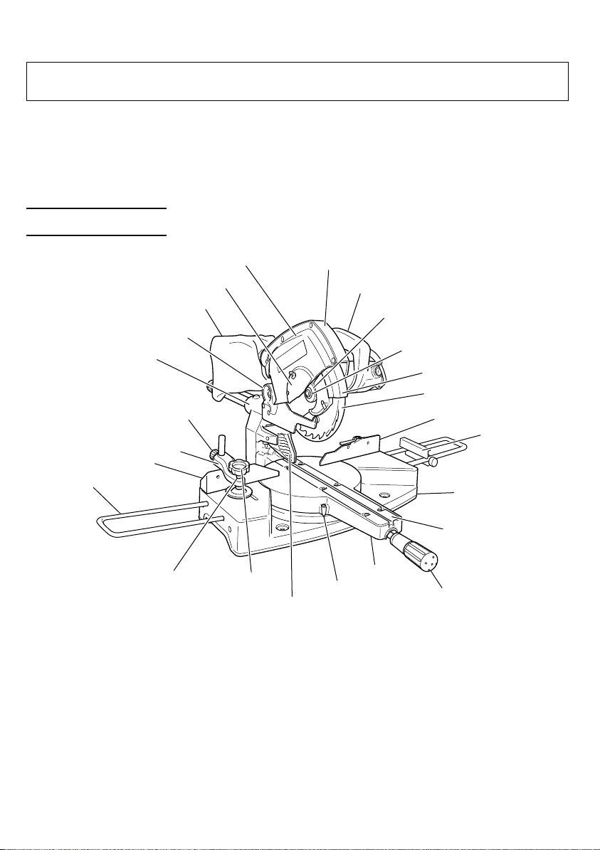
NAME OF PARTS
Holder
Holder (A)
6mm knob bolt
Screw holder
Fence (B)
Vise assembly
Saw cover
Spindle cover
Dust bag
Hinge
Knob
Guard
Fig. 1
Gear case
Indicator
Handle
Washer (C)
Bolt
Sub cover
Safety cover
Fence (A)
Stopper
Base
Table insert
Turntable
Side handle
8
Page 9
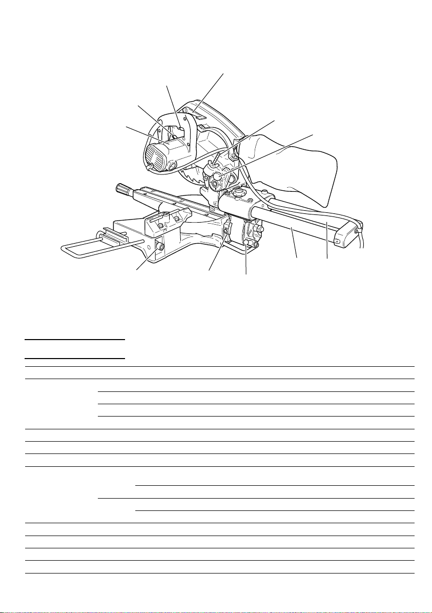
Spindle lock
Nameplate
Lock lever
Trigger switch
8mm depth adjustment bolt
Locking pin
Slide pipe (B)
6mm knob bolt
Indicator
Slide pipe (A)
Clamp lever
Fig. 2
SPECIFICATIONS
Item Model C8FSC
Motor Type Series commutator motor
Power source Single-phase AC 50Hz
Voltage (Volts) 240
Full-load current (Amp) 4.6
Applicable Outside Dia. 216mm (8-1/2")
saw blade Hole Dia. 30mm (1-3/16)
No load speed 4900/min
Bevel 0°
Max. sawing Miter 45° Max. Height 65mm (2-9/16") Width 220mm (8-21/32")
dimension
Miter sawing range Left 0° – 45° Right 0° – 57° (Bevel 45°, Left and Right 0° – 45° )
Bevel sawing range Left 0° – 45°
Net weight 17.5 kg (38.6 lbs)
Cord 2 Conductor type cable 2.5m (8ft.)
Bevel 45°
Miter 0°
Miter 0° Max. Height 39mm (1-9/16") Width 305mm (12")
Miter 45° Max. Height 39mm (1-9/16") Width 220mm (8-21/32")
Max. Height 65mm (2-9/16") Max. Height 75mm (2-15/16")
Max. Width 305mm (12") Max. Width 280mm (11")
()
9
Page 10
ACCESSORIES
WARNING: Accessories for this power tool are mentioned in this Handling
instructions.
The use of any other attachment or accessory can be dangerous and
could cause injury or mechanical damage.
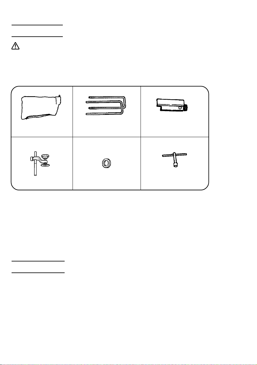
STANDARD ACCESSORIES
1 Dust bag (1 piece)
2 Holder (2 pieces)
3 Stopper (1 piece)
For how to use, refer to
page 23.
4 Vise assembly w/knob
bolt (1 piece)
For how to use, refer to
page 18.
For how to use, refer to
page 16.
5 Collar (1 piece)
Outside dia. 30mm (1 -3/16")
For how to use, refer to
page 24.
For how to use, refer to
page 16.
6 10mm box wrench (1 piece)
Fig. 3
OPTIONAL ACCESSORIES...sold separately
1 Extension Holder and Stopper (Fig. 1) (Code No. 998866)
2 Saw blade 216mm (8-1/2") TCT Saw blade (Total teeth: 24) (Code No. 998859)
NOTE: Accessories are subject to change without any obligation on the part of the
HITACHI.
APPLICATIONS
Wood and aluminum sash.
10
Page 11

PREPARATION BEFORE OPERATION
Make the following preparations before operating the power tool:
1. Installation
8mm (5/16") boltBase
150mm (5-29/32")
9mm (11/32")
3 Holes
264mm (10-13/32")
300mm (11-13/16")
Work bench 8mm (5/16") nut
Fig. 4
Attach the power tool to a level, horizontal work bench in accordance with Fig. 4.
Select 8mm (5/16") diameter bolts suitable in length for the thickness of the work bench.
Bolt length should be at least 25mm (1") plus the thickness of the work bench.
For example, use 50mm (2") or larger bolts for a 25mm (1") thick work bench.
The holder attached to the rear of the base helps stabilize the power tool.
Base holder adjustment:
Loosen the 6mm bolt with the supplied 10mm
box wrench.
Adjust the base holder until its bottom surface
contacts the work bench surface.
Holder
After adjustment, firmly tighten the 6mm bolt.
25mm (1") thick bench
Adjust the base
holder until its
bottom surface
contacts the work
bench surface.
6mm bolt
Move
Fig. 5
11
Page 12

2. Extension Cord
Ampere rating
(on nameplate) 6 Amp
Ext. cord length
7.5m 1.0mm
Wire gauge size
2
mm
(A.W.G )
2
(25ft.) (18 A.W.G)
15m 1.5mm
2
(50ft.) (16 A.W.G)
22.5m 2.0mm
2
(75ft.) (14 A.W.G)
30m 3.5mm
2
(100ft.) (12 A.W.G)
45m 3.5mm
2
(150ft.) (12 A.W.G)
60mm 5.5mm
2
(200ft.) (10 A.W.G)
To use the power tool when no suitable power
source is nearby, use an extension cord of
suitable size to ensure safety and to prevent
power loss and overheating.
Determine from the accompanying table the
required extension cord wire size.
Check power cords and extension cords for
loose or exposed wires and damaged
insulation before using.
Repair or replace as needed before using the
power tool.
NOTE: The lower the wire size number
means the heavier the wire and the
further it will carry current without
a voltage drop.
WARNING: Never connect this unit to an electrical power source until all
operating instructions have been read and understood.
3. Releasing the locking pin
When the power tool is prepared for shipping, its main parts are secured by a locking
pin. Move the handle slightly so that the locking pin can be disengaged and adjusted as
indicated in Fig. 7.
NOTE: Lowering the handle slightly will enable you to disengage the locking pin more
easily and safely.
During transport, fit the pin into the
deep slot.
Locking pin
Clockwise
During operation fit
Locking pin
Fig. 6
the pin stoppers into
the shallow slot.
Fig. 7
4. Installing the dust bag, holder, stopper and vises assembly.
Attach the dust bag, holder, stopper and vise assembly as indicated in Fig. 1.
12
Pull out to disengage.
Rotate the knob 1/4 turn
and fit the pin stoppers
into the shallow slot.
Page 13

BEFORE USING
1. Make sure the power source is appropriate for the tool.
WARNING: Never connect the power tool unless the available AC power source
is of the same voltage as that specified on the nameplate of the
tool.
Never connect this power tool to a DC power source.
2. Make sure the trigger switch is turned OFF.
WARNING: If the power cord is connected to the power source with the trigger
switch turned ON the power tool will start suddenly and can cause
a serious accident.
3. Check the saw blade for visible defects.
Confirm that the saw blade is free of cracks or other visible damage.
4. Confirm that the saw blade is attached securely to the power tool.
Using the supplied 10mm box wrench, tighten the bolt on the saw blade spindle to
secure the saw blade.
For details, see Fig. 30-a and Fig. 30-b in the section on “SAW BLADE MOUNTING AND
DISMOUNTING”.
5. Check the safety cover for proper operation.
This slide compound miter saw is equipped
with a saw head lock as safety device. To lower
Sub cover
Safety cover
Fig. 8
the saw head to cut, the lock must be released
by pressing the lock lever with your thumb.
When you push down the handle while
pushing the lock lever, check that the safety
cover and sub cover revolves smoothly.
Next, check that the safety cover and the sub
cover returns to the original position when the
handle is raised.
WARNING: NEVER OPERATE THE POWER TOOL if the safety cover does not
function smoothly.
6. Confirm the position of the spindle lock before using the tool.
After installing the saw blade, confirm that the spindle lock has been returned to the
retract position before using the power tool (see Fig. 2).
7. Check the lower limit position of the Saw Blade.
Although it was adjusted before shipment, carefully check the height of the saw blade.
Confirm that the saw blade can be lowered 12mm to 13mm (15/32" to 1/2") below the
table insert. For details, see the section on “Checking the saw blade lower limit position”.
8. Check the Power Receptacle.
To prevent overheating, accidental stopping or intermittent operation, confirm that the
power cord plug fits properly in the electrical receptacle and does not fall out after it is
inserted. Repair or replace the receptacle if it is faulty.
13
Page 14

9. Confirm the tool’s power cord is not damaged.
Repair or replace the power cord if an inspection indicates that it is damaged
AFTER CONNECTING THE POWER PLUG TO AN APPROPRIATE AC POWER SOURCE, CHECK
THE OPERATION OF THE TOOL AS FOLLOWS:
10. Trial Run
After confirming that no one is standing behind, the power tool start and confirm that
no operating abnormalities exist before attempting a cutting operation.
11. Inspect the rotating stability of the saw blade.
For precise cutting, rotate the saw blade and check for deflection to confirm that the
blade is not noticeably unstable; otherwise vibrations might occur and cause an accident.
12. Confirm the correct blade type.
Hitachi miter saws are primarily designed to cut timber.
However, by using the **correct blade type, other materials such as aluminium, other
non-ferrous metals and plastics, can be cut successfully.
** Please consult a saw blade specialist for the correct blade type.
BEFORE CUTTING
1. Cutting a groove on the guard
Vise
assembly
Fence (B)
Guard
Fence (A)
Workpiece
Fig. 9
2. Positioning the table insert
Holder (A) has a guard (see Fig. 9) into
which a groove must be cut.
After placing a suitable wooden piece to
sit on the fence and the table surfaces,
fix it with the vise assembly.
After the switch has been turned on and
the saw blade has reached maximum
speed, slowly lower the handle to cut a
groove on the guard.
CAUTION: Do not cut the groove
too quickly; otherwise
the guard might
become damaged.
6mm
machine
screw
14
Workpiece
(Left)
[Straight cutting]
Saw blade
Table insert
(Right)
Workpiece
(Left)
Saw blade
Table insert
[Bevel cutting]
Fig. 10-a Fig. 10-b
6mm
machine
screw
(Right)
Page 15

Adjust the table insert on the turntable until it is correctly aligned to the saw blade, as
indicated below.
Table insert adjustment:
(1) Loosen the 6mm machine screws securing the right side table insert.
(2) Check that the tabIe insert is positioned fully to the right, and temporarily tighten the
back and front 6mm machine screws.
(3) Secure a piece of wood (about 200mm (7-7/8") wide) to the turntable with the vise
assembly.
(4) Cut the piece of wood at the desired angle.
(5) Align the right side table insert with the cutting line as indicated in Figs. 10-a and 10-b.
(6) Securely tighten the back and front 6mm machine screws.
(7) Remove the workpiece, and securely tighten the center 6mm machine screws.
If the power tool is properly adjusted, cutting can be made accurate by aligning a
premarked ink line with the table insert.
When the power tool is shipped from the factory, the right side table insert is put in a
position where it will not contact the saw blade at a full 45° bevel cut.
Therefore, before operation, adjust the right side table insert to the desired cutting
angle.
3. Checking the saw blade lower limit position
8mm depth adjustment bolt
Table
insert
Turntable
Fig. 11
8mm wing nut
8mm nut
(2 pieces)
Check that the saw can be lowered 12mm to
13mm (15/32" to 1/2") below the table insert.
If necessary, adjust as follows:
(1) Loosen the 8mm wing nut and the two
8mm nuts on the 8mm depth adjustment
bolt.
(2) Turn the 8mm depth adjustment bolt as
necessary to set the lower limit position.
(3) Once the adjustment is complete, fully
tighten the two 8mm nuts and the 8mm
wing nut.
NOTE: Before tightening the two 8mm
nuts and the 8mm wing nut,
confirm that the saw blade is
adjusted so that it will not cut into
the turntable.
15
Page 16

4. Oblique angle
Before the power tool is shipped from the
factory, it is adjusted for 0°, right angle, Ieft
45° bevel cutting angle with the 8mm nylock
bolts.
The positioning and bevel cutting angle can
8mm nylock
bolt
be adjusted by loosening the 8mm nylock bolt
and by changing the height of the 8mm nylock
bolt.
(Maximum bevel cutting angle is 45°)
Fig. 12
5. Securing the workpiece
WARNING: Always clamp or vise to secure the workpiece to the fence;
otherwise the workpiece might be thrust from the table and cause
bodily harm.
6. Installing the holders (Standard Equipment)
The holders help keep longer workpieces
stable and in place during the cutting
6mm knob
bolt
Holder
operation.
(1) As indicated in Fig. 13, use a steel square
for aligning the upper edge of the holders
with the base surface.
(2) After aligning, secure the holders with the
6mm knob bolts.
Steel square Base surface
Fig. 13
7. Stopper for precision cutting (Standard Equipment)
The stopper facilitates continuous precision
cutting in lengths of 265mm to 430mm (10-7/
16" to 16-15/16").
To install the stopper, attach it to the holder
with the 6mm knob bolt as shown in Fig. 14.
16
Workpiece
Stopper
Move
6mm knob bolt
Fig. 14
Holder
Page 17

8. Using an ink line
Handle
Safety cover
Press down the handle to lift the safety
cover as shown in Fig. 15, and align the
premarked ink line with the saw blade.
Fence (B)
Marking
(pre-marked)
Fig. 15
CAUTION: Never lift the safety cover while the saw blade is rotating.
PRACTICAL APPLICATIONS
WARNING:* To avoid personal injury, never remove or place a workpiece on
the table while the tool is being operated.
* Never place your limbs inside of the line while the tool is being
operated. This may cause hazardous conditions (see Fig. 16).
Line
Fig. 16
Line
17
Page 18

1. Switch operation
The tool is turned on when the switch trigger
Trigger switch
is pulled and off when the trigger switch is
released (Fig. 17).
Fig. 17
2. Using the Vise Assembly (Standard accessory)
6mm
knob bolt
Screw holder
Knob
(1) The vise assembly can be mounted
on either the left fence {Fence (B)} or
the right fence {Fence (A)} by
loosening the 10mm knob bolt.
Vise shaft
Vise plate
(2) The screw holder can be raised or
lowered according to the height of the
Fence
workpiece by loosening the 6mm
knob bolt. After the adjustment, firmly
tighten the 6mm knob bolt and fix the
Workpiece
screw holder.
(3) Turn the upper knob and securely fix
10mm knob bolt
Fig. 18
the workpiece in position (Fig. 18).
18
CAUTION: Always confirm that the motor head (see Fig. 1) does not contact
the vise assembly when it is lowered for cutting. If there is any danger
that it may do so, loosen the 10mm knob bolt slightly and move the
vise to a position where it will not contact the saw blade.
Also, always confirm that the vise assembly is mounted on the right
side {Fence (A)} before using the saw for compound cutting
operations (miter + bevel cutting).
Page 19

3. Cutting Operation
Adjusting lineab
(1) As shown in Fig. 19 the width of the saw
blade is the width of the cut. Therefore,
slide the workpiece to the right (viewed
from the operator’s position) when length
b is desired, or to the left when length a
is desired.
(2) After turning on the switch and checking
that the saw blade is rotating at maximum
speed, slowly push down the handle while
holding down the lock lever and bring the
Marking
(pre-marked)
a
(Front View)
a
b
Marking
b
(pre-marked)
saw blade in the vicinity of the material to
Fig. 19
be cut.
(3) Once the saw blade contacts the
workpiece, push the handle down
gradually to cut into the workpiece.
(4) After cutting the workpiece to the desired
depth, turn the power tool OFF and let the
saw blade stop completely before raising
the handle from the workpiece to return it
to the full retract position.
CAUTION: *Increased pressure on the handle will not increase the cutting speed.
On the contrary, too much pressure may result in overload of the
motor and/or decreased cutting efficiency.
WARNING: * Confirm that the trigger switch is turned OFF and the power plug
has been removed from the receptacle whenever the tool is not in
use.
4. Cutting narrow workpieces (Press cutting)
Slide the hinge down to holder (A), then
Slide securing knob
Hinge
Handle
Press
down
tighten the slide securing knob as indicated
in Fig. 20.
Lower the handle to cut the workpiece.
Using the power tool this way will permit
cutting of workpieces of up to 65mm (2-9/16")
square.
Holder (A)
Workpiece
Fig. 20
19
Page 20

5. Cutting wide workpieces (Slide cutting)
1 Pull forward
3 Push rearward to cut
Fig. 21
Handle
2 Press
down
Workpiece
(1) Workpieces up to 65mm (2-9/16") high
(2) Workpieces up to 75mm (2-15/16") high
CAUTION: *If the handle is pressed down with excessive or lateral force, the
saw blade may vibrate during the cutting operation and cause
unwanted cutting marks on the workpiece, thus reducing the
quality of the cut.
Accordingly, press the handle down gently and carefully.
*In slide cutting, gently push the handle back (rearwards) in a single,
smooth operation.
Stopping the handle movement during the cut will cause unwanted
cutting marks on the workpiece.
WARNING: * For slide cutting, follow the procedures indicated above in Fig. 21.
Forward slide cutting (toward the operator) is very dangerous
because the saw blade could kick upward from the workpiece.
Therefore, always slide the handle away from the operator.
*Always return the carriage to the full rear position after each
crosscut operation in order to reduce the risk of injury.
*Never put your hand on the side handle during the cutting operation
because the saw blade comes close to the side handle when the
motor head is lowered.
and 305mm (12") wide:
Loosen the slide securing knob, grip the
handle and slide the saw blade forward.
Then press down on the handle and slide
the saw blade back to cut the workpiece
as indicated in Fig. 21. This facilitates
cutting of workpieces of up to 65mm (2-9/
16") in height and 305mm (12") in width.
and 280mm (11") wide:
Workpieces of up to 75mm (2-15/16") in
height and up to 280mm (11") in width can
be cut in the same manner as described
in paragraph 5-(1) above.
20
Page 21

6. Bevel cutting procedures
Loosen
Indicator
Tighten
Fig. 22
WARNING: When the workpiece is secured on the left or right side of the blade,
the short cut-off portion will come to rest on the right side of the
saw blade. Always turn the power off and let the saw blade stop
completely before raising the handle from the workpiece.
If the handle is raised while the saw blade is still rotating, the cut-off
piece may become jammed against the saw blade causing fragments
to scatter about dangerously.
When stopping the bevel cutting operation halfway, start cutting
after pulling back the motor head to the initial position.
Starting from halfway, without pulling back, causes the safety cover
to be caught in the cutting groove of the workpiece and to contact
the saw blade.
Scale
Clamp lever
(1) Loosen the clamp lever and bevel the saw
blade to the left.
(2) Adjust the bevel angle to the desired
setting while watching the scale and
indicator, then secure the clamp lever.
(3) Follow the procedures indicated in
paragraphs 4 and 5 above. For maximum
dimensions for bevel cutting of up to
39mm (1-9/16") in height and 305mm (12")
width.
7. Miter cutting procedures
Angle scale
Grade scale
Miter scale
Fig. 23
Fig. 24
(1) Loosen the side handle and adjust the
turntable until the indicator aligns with
desired setting on the miter scale (Fig. 25).
a
(2) Re-tighten the side handle to secure the
turntable in the desired position.
(3) The miter scale (Fig. 23) indicates both the
cutting angle on the angle scale and the
gradient on the grade scale.
(4) The gradient, which is the ratio of the
height to the base of the triangular section
to be removed, may be used for setting
the miter scale instead of the cutting
angle, if desired (see Fig. 24).
(5) Therefore, to cut a workpiece at a grade
of 2/10, set the indicator to position a as
indicated in Fig. 23.
21
Page 22

NOTE:* Positive stops are provided at the right
and left of the 0° center setting, at 15°,
22.5°, 30° and 45° settings.
Indicator
Turn the
turntable
Check that the miter scale and the tip
of the indicator are properly aligned.
* Operation of the saw with the miter
Miter
scale
Loosen
Side handle
Tighten
scale and indicator out of alignment,
or with the side handle not properly
tightened, will result in poor cutting
precision.
Fig. 25
8. Compound cutting
Compound cutting can be performed by following the instructions in 6 and 7 above.
At a bevel angle of 45° and a miter angle of 45°, a workpiece of 39mm (1-9/16") in height
and up to 220mm (8-21/32") in width can be cut.
CAUTION: Always secure the workpiece with the right hand side for compound
cutting. Never rotate the turntable to the right for compound cutting,
because the saw blade might then contact the clamp or vise that
secures the workpiece, and cause personal injury or damage.
9. Groove cutting procedures
Cut grooves with saw blade
8mm depth adjustment bolt
Turntable
Fig. 27
Fig. 26
8mm wing nut
Bottom line of
the groove
Grooves in the workpiece can be cut as indicated in Fig. 46 by adjusting the 8mm depth
adjustment bolt.
Cutting depth adjustment procedure:
(1) Loosen the 8mm wing nut and turn the 8mm depth adjustment bolt by hand.
(2) Adjust to the desired cutting depth by setting the distance between the saw blade
and the surface of the base (see b in Fig. 26).
(3) The 8mm wing nut must be properly tightened after the adjustment has been
completed.
22
Page 23

NOTE: When cutting a single groove at either end of the workpiece, remove the
unneeded portion with a chisel.
10. Cutting easily-deformed materials, such as aluminum sash
Materials such as aluminum sash can easily deform when tightened too much in a vise
assembly. This will cause inefficient cutting and possible overload of the motor.
When cutting such materials, use a wood plate to protect the workpiece as shown in
Fig. 28.
When cutting aluminum materials, coat the saw blade with cutting oil (non-combustible)
to achieve smooth cutting and a fine finish.
Vise assembly
Fence
10mm knob bolt
Wood plate
Aluminum
sash
Fig. 28
11. How to use the dust bag (Standard accessory)
Dust bag
Right angle
Duct
Saw cover
Fig. 29
(1) When the dust bag has become full of
sawdust, dust will be blown out of the dust
bag when the saw blade rotates.
Check the dust bag periodically and empty
it before it becomes full.
(2) During bevel and compound cutting,
attach the dust bag at a right angle to the
base plate as shown in Fig. 29.
CAUTION: Empty the dust bag frequently to prevent the duct and the safety
cover from becoming clogged.
Sawdust will accumulate more quickly than normal during bevel
cutting.
Wood plate
SAW BLADE MOUNTING AND DISMOUNTING
WARNING: * To prevent an accident or personal injury, always turn off the trigger
switch and disconnect the power plug from the receptacle before
removing or installing a saw blade.
23
Page 24

1. Mounting the saw blade (Fig. 30-a and Fig. 30-b)
(1) Press in spindle lock and loosen bolt with 10mm box wrench (standard accessory).
Since the bolt is left-hand threaded, loosen by turning it to the right as shown in
Fig. 30-b.
NOTE: If the spindle lock cannot be easily pressed in to lock the spindle, turn the
bolt with 10mm box wrench (standard accessory) while applying pressure
on the spindle lock.
The saw blade spindle is locked when the spindle lock is pressed inward.
Spindle lock
Fig. 30-a
Tighten
Fig. 30-b
Washer (C)
Bolt
Loosen
(2) Remove the bolt, washer (C) and collar.
(3) Before mounting the saw blade, carefully clean and re-install the collar. The collar
has out -side diameters of 30mm (1-3/16") as shown in Fig. 31.
Washer (C)
15.9mm (5/8")
30mm (1-3/16")
Collar
Saw blade
Washer (C)
Bolt 10mm box wrench
Fig. 31
(4) Lift the safety covers (safety covers and sub cover) and mount the saw blade.
WARNING: When mounting the saw blade, confirm that the rotation indicator
mark on the saw blade and the rotation direction of the saw are
properly matched.
(5) Thoroughly clean washer (C) and the bolt, and install them onto the saw blade
spindle.
(6) Press in the spindle lock and tighten the bolt by turning it to the left by 10mm box
wrench as indicated in Fig. 30-b.
24
Page 25

CAUTION: *Confirm that the spindle lock has returned to the retract position
after installing or removing the saw blade.
*Tighten the bolt so it does not come loose during operation.
Confirm the bolt has been properly tightened before the power
tool is started.
2. Dismounting the saw blade
Dismount the saw blade by reversing the mounting procedures described in paragraph
1 above.
The saw blade can easily be removed after lifting the safety cover.
CAUTION: Never attempt to install saw blades larger than 216mm (8-1/2") in
diameter.
Always install saw blades that are 216mm (8-1/2") in diameter or
less.
MAINTENANCE AND INSPECTION
WARNING: To avoid an accident or personal injury, always confirm that the
trigger switch is turned OFF and the power plug has been
disconnected from the receptacle before performing any
maintenance or inspection of this tool.
1. Inspecting the saw blade
Always replace the saw blade immediately upon the first sign of deterioration or damage.
A damaged saw blade can cause personal injury and a worn saw blade can cause
ineffective operation and possible overload to the motor.
CAUTION: Never use a dull saw blade. When a saw blade is dull, its resistance
to the hand pressure applied by the tool handle tends to increase,
making it unsafe to operate the power tool.
2. Adjusting a loose slide pipe
After extended use of the power tool, the slide
8mm hex. socket
set screw
Fig. 32
Bushing
8mm nut
Slide pipe (A)
pipe (A) and the bushing can become loose
due to vibration. Never operate the tool if any
components are loose to avoid personal
injury.
(1) Loosen the 8mm nut and tighten the four
8mm hexagon socket set screws until the
power tool operates smoothly without
looseness. (Fig. 32)
(2) Properly tighten the 8mm nut after
completing these adjustment.
25
Page 26

3. Inspecting the carbon brushes (Fig. 33 and Fig. 34)
The carbon brushes in the motor are expendable parts.
If the carbon brushes become excessively worn, motor trouble might occur.
Therefore, inspect the carbon brushes periodically and replace them when they have
become worn to the wear limit line as shown in Fig. 33.
Also, keep the carbon brushes clean so that they will slide smoothly within the brush
holders.
The carbon brushes can easily be removed after removal of the brush caps (see Fig. 34)
with a slotted (minus) screwdriver.
Wear limit line
43
Brush cap
6mm (1/4")
17mm (11/16")
No. 43 indicates the last
two numbers of carbon
brush Code No.
Groove for driver
Fig. 33
Fig. 34
4. Inspecting the screws
Regularly inspect each component of the power tool for looseness.
Re-tighten screws on any loose part.
WARNING: To prevent personal injury, never operate the power tool if any
components are loose.
5. Inspecting the safety cover for proper operation
Before each use of the tool, test the safety covers (see Fig. 8) to assure that they are in
good condition and that they move smoothly.
Never use the tool unless the safety cover operates properly and unless they are in
good mechanical condition.
6. Storage
After operation of the tool has been completed, check that the following has been
performed:
(1) Trigger switch is in OFF position,
(2) Power plug has been removed from the receptacle an stored in a secure place.
When the tool is not in use, keep it stored in a dry place out of the reach of children.
7. Lubrication
Lubricate the following sliding surfaces once a month to keep the power tool in good
operating condition for a long time (see Fig. 1 and Fig. 2). Use of machine oil is
recommended.
Oil supply points:
*Rotary portion of hinge
*Rotary portion of vise assembly
*Sliding portion of slide pipe (A) and slide pipe (B)
26
Page 27

8. Cleaning
Periodically remove chips, dust and other waste material from the surface of the power
tool with a damp, soapy cloth. To avoid a malfunction of the motor, protect it from
contact with oil or water.
SERVICE AND REPAIRS
All quality power tools will eventually require servicing or replacement of parts because of
wear from normal use. To assure that only authorized replacement parts will be used and
that the double insulation system will be protected, all service (other than routine
maintenance) must be performed by an AUTHORIZED HITACHI POWER TOOL REPAIR
CENTER ONLY.
NOTE: Specifications are subject to change without any obligation on the part of
HITACHI.
27
Page 28

28
Page 29

Item
No.
1 MACHINE SCREW M4×16 1
2 BOLT WASHER M4 1
3 NYLON CLIP 2
4 HINGE ASS'Y (INCLUD.5) 1
5 SUPPORT 1
6 ROLL PIN D6×40 2
7 MACHINE SCREW M5×12 2
8 PACKING COVER 2
9 FELT 4
10 BALL BUSHING 1
11 BUSHING 4
12 HEX. SOCKET SET SCREW M8×81
13 BEARING LOCK 1
14 KNOB BOLT M8×20 1
15 LOCK SPRING 1
16 LOCK NUT M8 4
17 HEX. SOCKET SET SCREW M8×16 4
18 GUARD 1
19 BOLT WASHER M8 1
20 SPRING WASHER M8 1
21 MACHINE SCREW M8×30 1
22 HANDLE 1
23 WING NUT M8 1
24 SEAL LOCK HEX. SOCKET HD. BOLT M5×10 1
25 GEAR CASE (A) 1
26 HEX. SOCKET SET SCREW M6×16 1
27 SLEEVE 1
28 SPRING 1
29 NUT M8 2
30 BOLT M8×100 1
31 STOP SPRING 1
32 SPACER 2
33 WASHER 2
34 SEAL LOCK MACHINE SCREW M5×12 2
35 LOCK LEVER 1
36 STOPPER PIN 1
37 MACHINE SCREW (W/WASHERS) M5×20 1
38 COLLAR (B) 1
39 SPRING 1
40 RETAINING RING (E-TYPE) FOR D7 SHAFT 1
41 SET PIN 1
42 GAUGE SPRING 1
43 ROLL PIN D3×20 1
44 GRIP 1
45 HINGE SHAFT (A) 1
46 MACHINE SCREW (W/WASHERS) M4×12 1
47 CLAMP LEVER 1
48 BOLT (LEFT HAND) M10 1
49 WASHER (I) 1
50 CAP NUT M12 1
51 NUT M12 1
52 BOLT WASHER M12 1
53 HOLDER (A) 1
54 CAUTION LABEL (A) 1
55 TABLE INSERT 2
56 MACHINE SCREW M6×20 6
57 NYLOCK BOLT M8×25 2
58 SLOTTED PIN D8×30 1
59 HOLDER SHAFT 1
60 INDICATOR 1
Part Name Q’TY
Item
No.
61MACHINE SCREW (W/WASHERS) M6×10 1
62 SHAFT 1
63 MACHINE SCREW (W/WASHERS) M4×12 1
64 INDICATOR 1
65 FLAT HD. SCREW M6×16 2
66 HINGE ARM 1
67 TURN TABLE (A) 1
68 SPRING (C) 1
69 STEEL BALL D12.7 1
70 LINER 3
71 BASE ASS'Y (INCLUD.72-77) 1
72 BOLT M6×16 1
73 HOLDER 1
74 KNOB BOLT M6×52 2
75 BASE RUBBER 5
76 BOLT WASHER M5 5
77 MACHINE SCREW M5×20 5
78 VISE ASS'Y (INCLUD.79-85) 1
79 KNOB BOLT M10 1
80 KNOB BOLT M6×11 1
81 WASHER 1
82 VISE PLATE SET 1
83 WASHER 1
84 MACHINE SCREW (W/WASHERS) M5×12 1
85 VISE SHAFT 1
86 KNOB BOLT M10×70 1
87 FENCE (B) 1
88 BOLT (W/WASHERS) M8×35 2
89 SPACER 1
90 MACHINE SCREW M4×10 1
91 SIDE HANDLE 1
92 SHAFT 1
93 RETAINING RING (E-TYPE) FOR D7 SHAFT 1
94 BOLT (W/WASHERS) M8×35 2
95 FENCE (A) 1
96 GUIDE ASS'Y (INCLUD. 74, 97-99) 1
97 STOPPER 1
98 KNOB BOLT M6×11 1
99 HOLDER 1
100 WASHER (T) 1
101 NUT M12 1
102 LOCK NUT M12 1
Part Name Q’TY
29
Page 30

30
Page 31

Item
No.
131 RUBBER RING 1
132 ARMATURE ASS'Y (INCLUDE. 133, 135) 1
133 BALL BEARING 6001VVCMPS2L 1
134 BEARING LOCK 1
135 BALL BEARING 608VVC2PS2L 1
136 FAN GUIDE (B) 1
137 MACHINE SCREW (W/WASHERS) M5×60 2
138 STATOR ASS'Y (INCLUD139) 1
139 BRUSH TERMINAL 2
140 HANDLE COVER 1
141 SWITCH (2P PILLAR TYPE) W/O LOCK 1
142 NAME PLATE 1
143 TAPPING SCREW (W/FLANGE) D4×25 3
144 MACHINE SCREW (W/WASHERS) M5×50 3
145 TAIL COVER 1
146 TAPPING SCREW (W/FLANGE) D4×20 1
147 CORD 1
148 NOISE SUPPRESSOR 1
149 TAPPING SCREW (W/WASHER) D4×16 2
150 CORD CLIP 1
151 TUBE (D) 1
152 CORD ARMOR 1
153 CARBON BRUSH 2
154 BRUSH CAP 2
155 HOUSING ASS'Y (INCLUD.157, 158) 1
156 HEX. SOCKET SET SCREW M5×62
157 BRUSH HOLDER 2
158 WASHER (B) 1
159 TAPPING SCREW (W/FLANGE) D4×25 1
160 MACHINE SCREW (W/WASHERS) M5×81
161 DUCT 1
162 NYLON CLIP D6.3 1
163 MACHINE SCREW (W/WASHERS) M5×16 1
164
FLAT HD.SCREW (W/TOOTHED LOCK WASH)M5×35
165 COVER HOLDER 1
166 SPINDLE ASS'Y (INCLUD.168-170) 1
167 BALL BEARING 6004VVCMPS2L 1
168 BEARING HOLDER 1
169 BALL BEARING 608VVC2PS2L 1
170 PAN HD. SCREW M5×10 4
171 SAW COVER ASS'Y (INCLUD.173-178) 1
172 HITACHI LABEL 1
173 MACHINE SCREW (W/WASHERS) M5×81
174 SPACER 1
175 WING NUT M5 1
176 WASHER M5 1
177 SPINDLE COVER 1
178 BOLT (LEFT HAND) W/WASHER M7×17.5 1
179 WASHER (C) 2
180 COLLAR (A) FOR D30 HOLE 1
181
FLAT HD. SCREW(W/TOOTHED LOCK WASH)M4×12
182 COVER 1
183 SAFETY COVER 1
184 TAPPING SCREW D4×10 1
185 SUB PLATE 1
186 RETURN SPRING 1
188 SUB COVER 1
501 DUST BAG 1
502 BOX WRENCH 10MM 1
601 TCT SAW BLADE 216MM-D30 HOLE-NT24 1
Part Name Q’TY
2
2
31
Page 32

Hitachi Koki Co., Ltd.
706
Code No. C99164611 N
Printed in Japan
 Loading...