

Hitachi C21-TF641S, C21-TF641SN, C21-TF641ST, C21-TF641SNT, C21-TF651S Service Manual
...
…
…
…
…
…
…
HITACHI
HITACHI
HCPT
C21-TF641S/SN/ST/SNT
C21-TF651S/SN/ST/SNT
T1-001
SERVICE MANUAL
C21-TF751S/SN/ST/SNT
C21-TF571S/SN/ST/SNT
T1 Chassis
CAUTION :
CONTENTS
SAFETY PRECAUTIONS ...………………...…………….……………………………………………
PRODUCT SAFETY NOTICE …………...…………….………...……………...…………….………
REMOTE CONTROL UNIT ……………..………...…………….……………………………………
Before servicing this chassis, it is important that the service techician reads the " Safety Precaution "
and " Product Safety Notices " in this Service Manual.
2
2
3
GENERAL OPERATIONS GUIDE .………………...…………….……………………………………
CIRCUIT DESCRIPTION …………...…………….……………………………………………………
ADJUSTMENT INSTRUCTIONS ……………………...…………….…………………………………
REPLACEMENT PARTS LIST …………………...…………….………………………………………
SPECIFICATIONS AND PARTS ARE SUBJECT TO CHANGE FOR IMPROVEMENT.
COLOR TELEVISION
4
5
6
12
MARCH 2005 Hitachi Consumer Products ( THAILAND ) , Ltd.

SAFTY PRECAUTIONS
WARNING: The following precautions should be
opserved.
1. Do not install , remove, or handle the picture tube in could produce X-radiation moderately in excess of de any manner unless shatter proof goggles are worn. sign levels. The high voltage must not, under any cir People not so equipped should be kept away while cumstances, exceed 32kV on the chassis.
picture tubes are handled. Keep picture tube away
from the body while handing.
2. When service is required, an isolation transformer receiver is the picture tube. The tube utilized for the
should be inserted between power line and the above mentioned function in this chassis is specially
receiver before any service is performed on the constructed to limit X - radiatuion.
chassis. For continued X-radiation protection, replace tube with
3. When replacing the chassis in the cabinet,ensure
all the protective devices are put back in place,such
as barriers, non - metallic knobs, adjustment or
compartment covers or shields, isolation resistors/ Many electrical and mechanical parts in HITACHI
capacitors, etc. television receiver have special safety related
4. When service is required, observe the original lead evident from visual inspection, nor can be protection
dressing. Extra precaution should be taken to afforded by them necessarily be obtained by using
assure correct lead dressing in the high voltage
circuitry area. Particularly note the R. G. B. lead wattage, etc. Replacement parts which have these
dressing. Ensure they are dressed well away from special safety characteristics are identified by marking
the horizontal scan and F.B.T. circuitry. with a on the schematics and replacement
5. Always use the manufacturer ' s replacement
component. Always replace original spacers and safety characteristics as the HITACHI recommended
maintain lead lengths. Especially critical components replacement one, shown in the parts list in this Service
are indicated thus on the parts list and Manual, may create electrical shock, fire, X - radiation,
should not be replaced by other makes.
Furthermore, where a short circuit has occurred,
replace those components that indicate evidence of Product Safety is continuously under review and new
overheating. instructions are issued from time to time. For the latest
6. Before returning a serviced receiver to the customer, Manual. A subscription to ,or additional copies of
the service technician must thoroughly test the unit HITACHI Service Manuals may be obtained at a nominal
to be certain that it is completely safe to operate charge from your HITACHI sales offices.
without danger of electrical shock, and be sure that
no protective device built into the instrucment by the
manufacturer has became defective, or inadvertenly The line output stage can develop voltages in excess
damaged during servicing. Therefore, the following of 25 kV; if the E.H.T cap is required to be removed,
checks are recommended for the continued discharge the anode cap to chassis via a high value
protection of the customers and service techninians. resistor, prior to its removal from the tube.
HIGH VOLTAGE
High voltage should always be kept at the rated value
of the chassis and no higher. Operating at higher
voltages may cause a failure of the picture tube or high
voltage supply, and also, under certain circumstances
X-RADIATION
TUBES : The primary source of X - radiation in this
the same type as the original, HITACHI approved type.
PRODUCT SAFETY NOTICE
characteristics. These characteristics are often not
replacement components rated for higher voltage,
parts list in this Service Manual.The use of a substitute
replacement component which does not have the same
or other hazards.
information,always consult the current HITACHI Service
TUBE DISCHARGE
INSULATION
Insulation resistantce should not be less than 4.5 Mohm
at 500 VDC between the mains poles and any accessible
metal parts. Also, no flashover or breakdown should
occur during the dielectric strength test, applying 3.2kV
AC for two seconds between the main poles and
accessible metal parts.
- 2 -
R
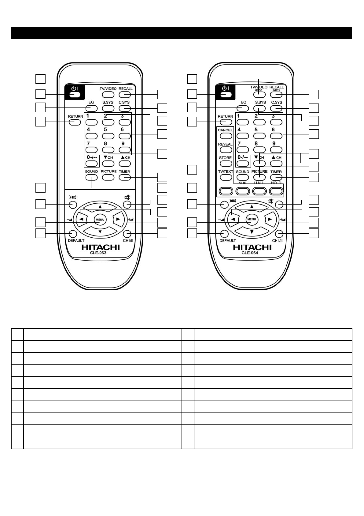
REMOTE CONTROL UNIT
19
16
10
11
2
1
6
7
5
17
18
14
4
8
9
12
3
15
13
19
16
20
10
11
2
1
6
7
5
17
18
14
4
9
8
12
3
15
13
Models without Teletext Models with Teletext
1. 11.
POWER ON/OFF SWITCH DEFAULT
2. 12.
INPUT SELECTOR MUTE
3. 13.
VOLUME UP/DOWN CHI/II (FOR NICAM/A2 MODELS)
4. 14.
PROGRAMME UP/DOWN PROGRAMME SELECTOR (DIRECT KEY)
5. 15.
RECALL CURSO
6. 16.
SURROUND SOUND RETURN
7. 17.
MENU COLOR SYSTEM
8. 18.
TIMER SOUND SYSTEM
9. 19.
PICTURE EQUALIZER
10. 20
SOUND T/TEXT FUNCTION KEY (T/TEXT MODELS ONLY)
- 3 -
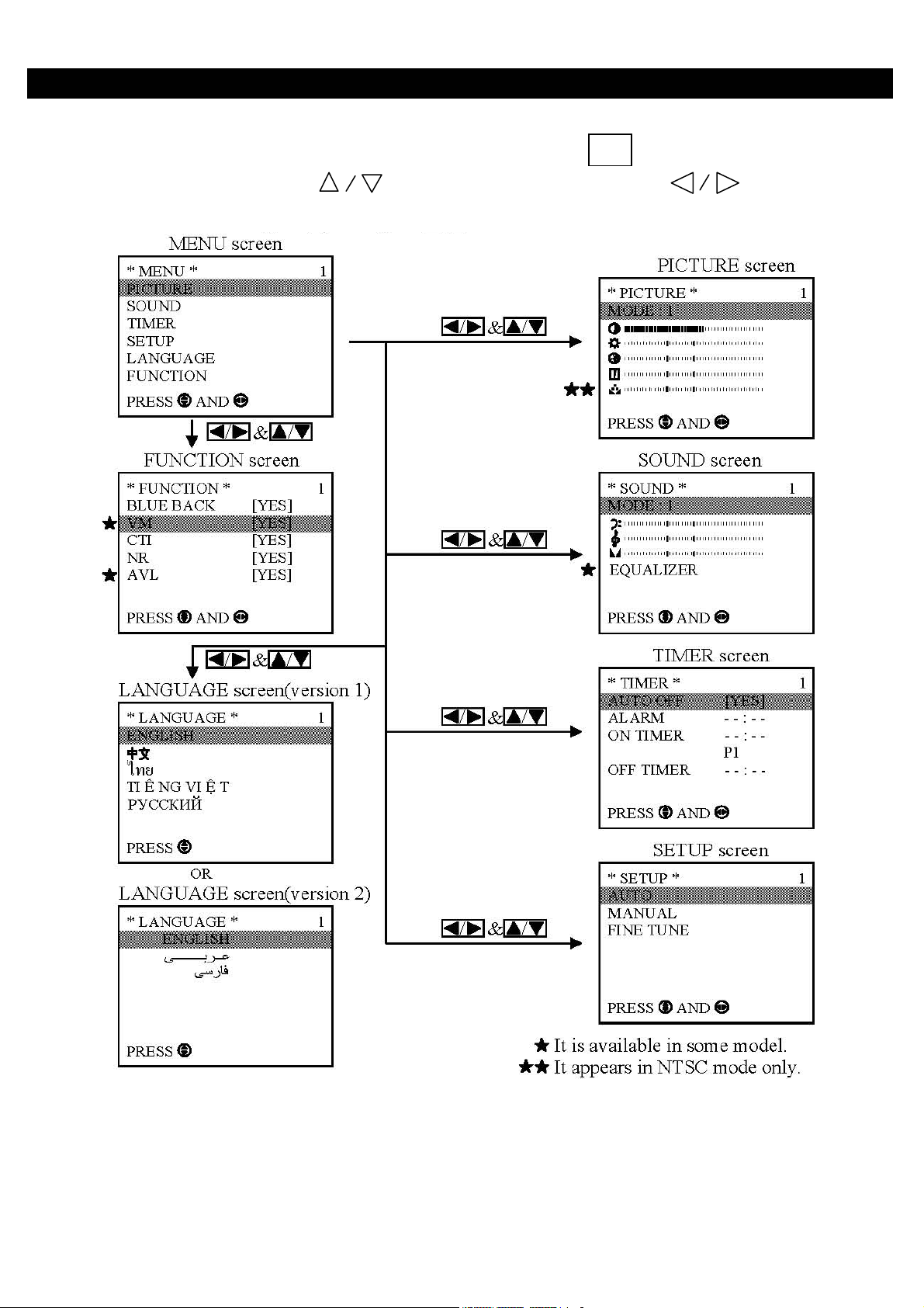
GENERAL OPERATIONS GUIDE
With this set, all adjustments/settings are performed by selecting from menu screens. Different menu screens and details
of adjustments/settings are shown below. To access the menu screen, press the button, then select the item by
pressing the up/down cursor buttons and adjust by the left/right cursor buttons .
MENU
- 4 -
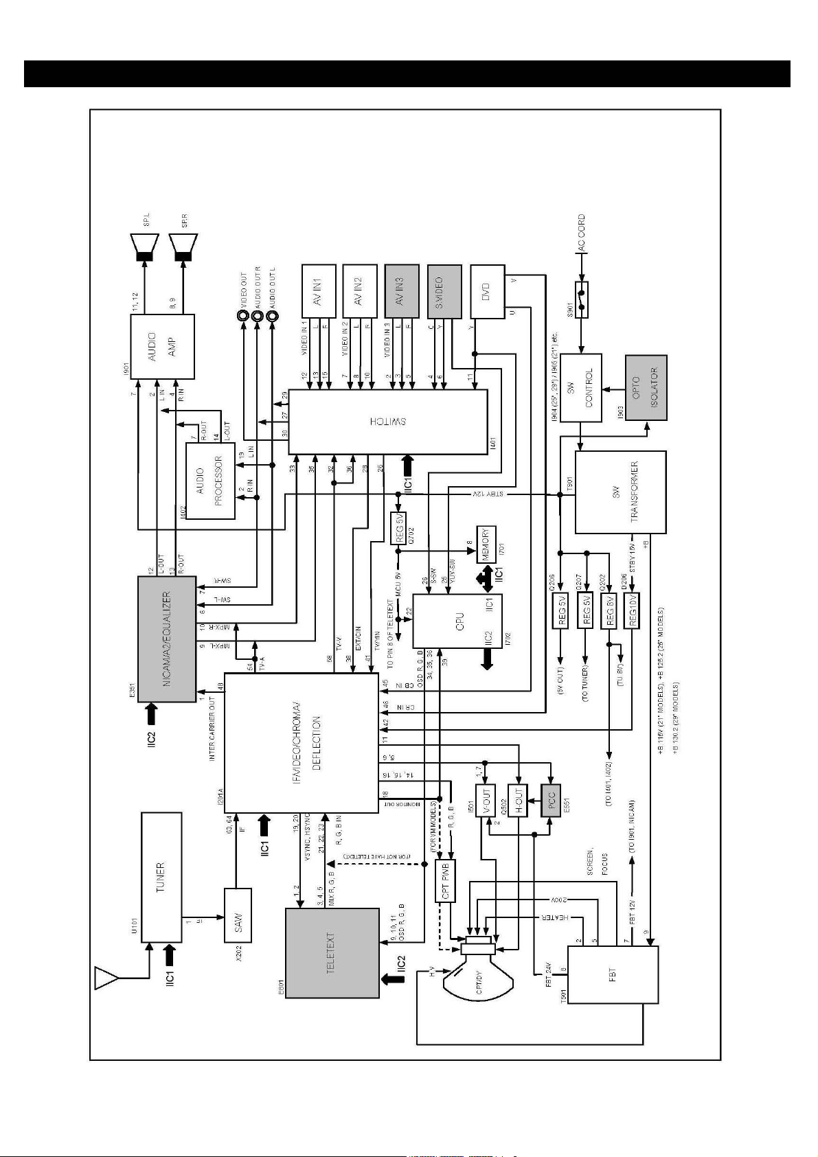
BLOCK DIAGRAM
- 5 -
A
A
DJUSTMENT INSTRUCTIONS
HOW TO GO TO SERVICE MODE
1. How to go to adjustment mode no 001 ~ 022
Procedure
(1) Turn TV off by power switch on the TV set.
(2) Press " FUNCTION " button on the TV set and kept depress the button.
(3) Turn TV on by power switch on the TV set.
2. How to go to adjustment mode no 101 ~ 328
Procedure
(1) Set volume to be “0”.
(2) Press button on remote control to go to standby mode.
(3) Press “TV/VIDEO” button on the TV set, and kept depress the button.
(4) Press button on remote control to go to operation mode.
(5) TV will show service table,then please cancel to keep depress the "TV/VIDEO" button.
Note : 1. Press the UP/DOWN cursor buttons
2. Adjust data by the left/right cursor buttons .
3. Press "RECALL" buttons to restore the data.
+B ADJUSTMENT
PREPARATION PROCEDURES
1
AC input voltage 230 +
2 Turns on the set and set the brightness and contrast +B voltage : TP902
to Max.(Signal : Philips Pattern) GND : TP901
3 After 30 sec heat-run, check & adjust the +B voltage
FREE RUN FREQUENCY ADJUSTMENT
Receive a PAL-I monoscope signal on TV mode.
1
5V(50Hz)
PREPARATION PROCEDURES
to select adjustment mode no.
1
1
djust R954 to obtain +B voltage as below
Select adjustment mode no. 1 and press "MENU" button
one time.
VIF-VCO FREE RUN FREQUENCY ADJUSTMENT
PREPARATION PROCEDURES
Receive a PAL-I monoscope signal on TV mode.
1
Select adjustment mode no. 2 and press "MENU" button
1
one time.
- 6 -
SOUND TRAP FREQUENCY ADJUSTMENT
A
PREPARATION PROCEDURES
Receive a PAL-I monoscope signal on TV mode.
1
Select adjustment mode no. 3 and press "MENU" button
1
one time.
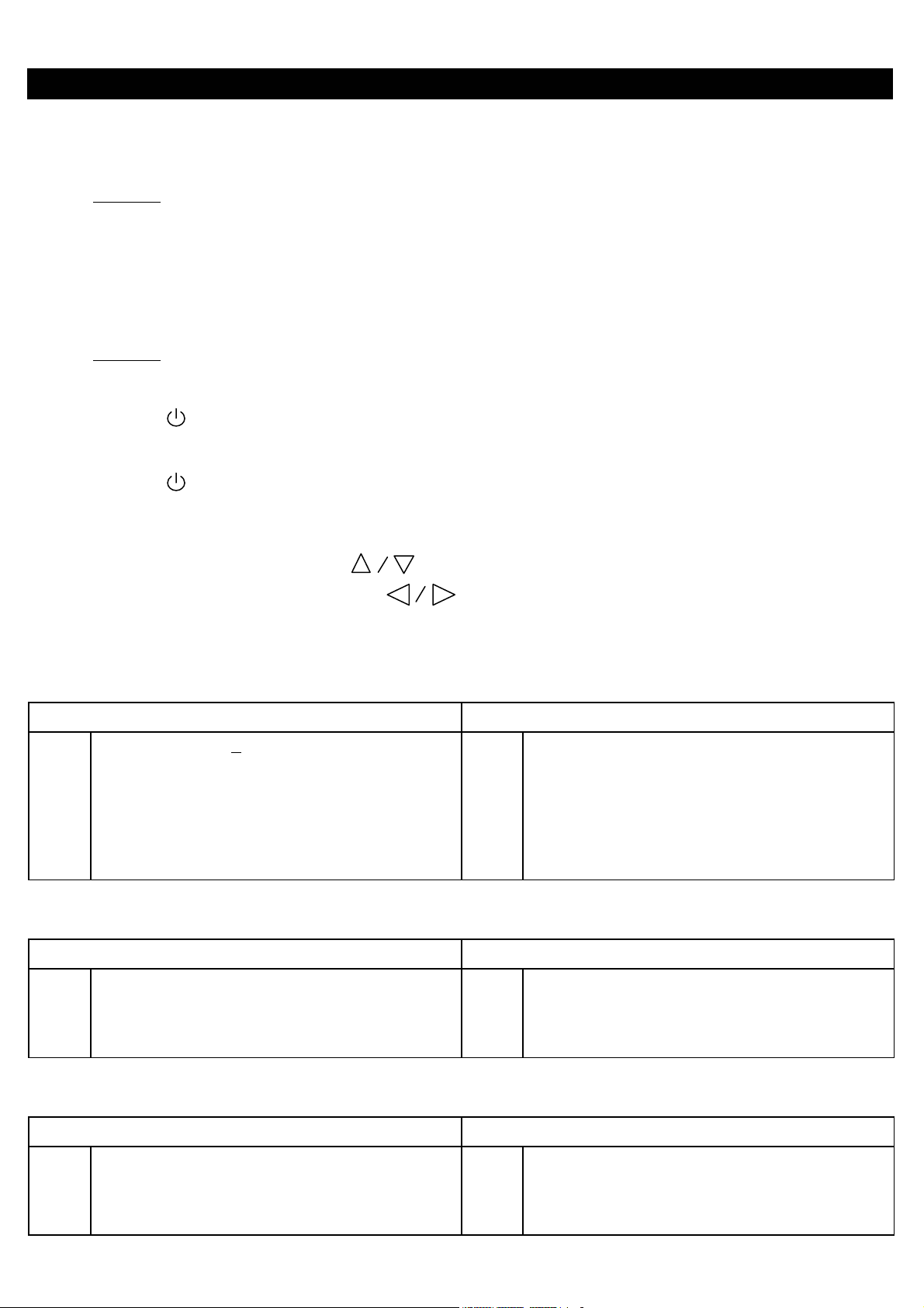
SECAM R-Y OFFSET ADJUSTMENT
PREPARATION PROCEDURES
1 Receive a secam color bar signal on Video 2. 1 Select adjustment mode no. 4.
2 Connect oscilloscope probe to pin 5 of E701. 2 Adjust output level at pin 5 of E701 as indicated below
using service mode no. 4.
0 +
0.1 V
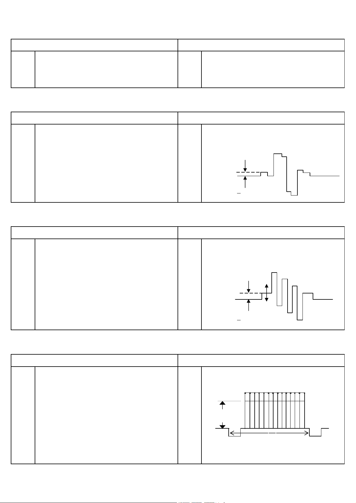
SECAM B-Y OFFSET ADJUSTMENT
PREPARATION
1 Receive a secam color bar signal on Video 2. 1
2 Connect oscilloscope probe to pin 5 of E701. 2
Select adjustment mode no. 5.
djust output level at pin 5 of E701 as indicated below
PROCEDURES
using service mode no. 5.
0.1 V
0 +
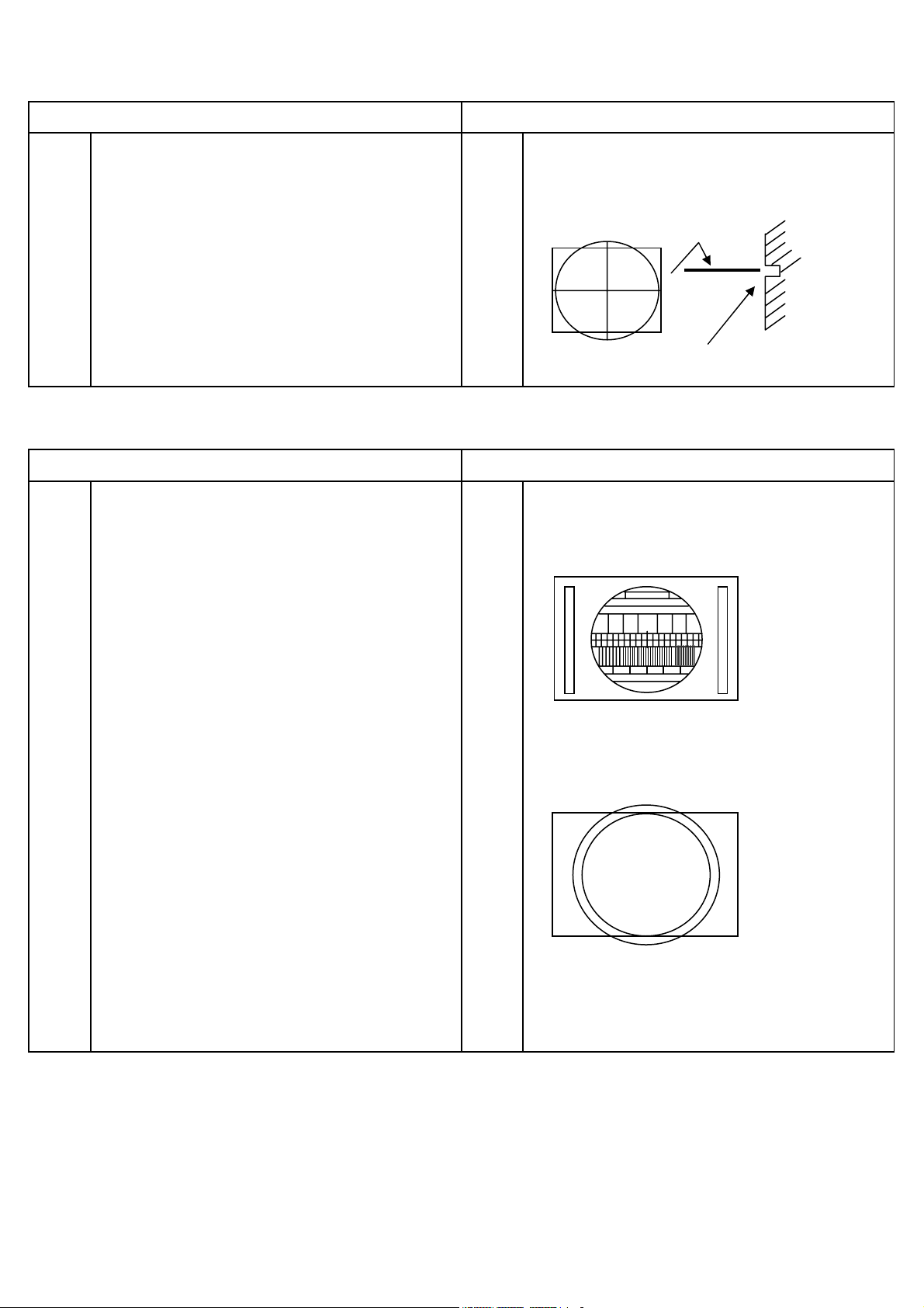
WHITE PEAK LEVEL ADJUSTMENT
PREPARATION PROCEDURES
1 Connect oscilloscope probe to pin 3 of E202 on CPT 1 Adjust output level at pin 3 of E202 as indicated below
P.W.B with respect to ground. using service mode no. 15.
2 Input PAL cross hatch signal to Video 2 terminal.
Cross hatch signal input level : 1 Vpp + 10%(with load
A
75 ohm) or 2 Vpp + 10%(no load).
3 Set CONTRAST to MAX.
1H
4 Set data in adjustment mode no.15 to 90. A = 2.8 + 0.1Vpp
- 7 -
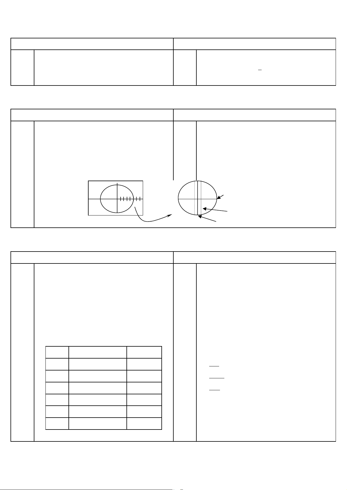
VERTICAL SHIFT ADJUSTMENT
PREPARATION PROCEDURES
1 Preheat more than 5 minutes of power supply. 1 Select the IIC control address No. 11.
2 Receive PAL Philips pattern signal. 2 Set the horizontal center line to vertical center maker
of CRT by adjustment of IIC.
Vertical center marker of CRT
VERTICAL SIZE ADJUSTMENT
PREPARATION PROCEDURES
1 Preheat more than 5 minutes of power supply. 1 Select the IIC control address No. 12.
2 Receive Philips pattern signal. 2 Adjust IIC data to obtain the following conditions.
PAL
Check vertical amplitude as below by
3
NTSC circle pattern.
NTSC
4 If picture isn't center, go back to IIC control No. 11 and
adjust IIC data to obtain the following conditions.
- 8 -
HORIZONTAL CENTER ADJUSTMENT
s
PREPARATION PROCEDURES
1 Side pin adjustment should be already completed. 1 Adjust adjustment mode no. 13 so that the average
2 Receive circle pattern signal. reading of R and L is 2.0 +
0.5 at circle pattern signal.
FOCUS ADJUSTMENT
PREPARATION PROCEDURES
1 Receive Philips pattern signal. 1 Set picture to mode 1
2 Vertical amplitude adjustment should be already 2 Turn the focus VR gradually clockwise from the full
completed. counterclockwise and adjust so that the halo of vertical
3 Adjust the cut-off after pre-adjust focus VR. center line does not appear, and horizontal line is
4 Check the cut-off in case focus is re-adjusted MIN. width.
HORIZONTAL
1 2 3 4 5 6 7
NO.5
ZOOM
HALO
VERTICAL
WHITE BALANCE ADJUSTMENT
PREPARATION PROCEDURES
1 Adjust the W/B after the Power is turned ON for 20 minute
1 Turn the screen adjusting VR clockwise and set it to the
2 Purity adjustment should be completed. position where the bright line starts appearing on CPT
3 Set the vertical incident illumination on the CPT surface screen.
to 20 lux or less. 2 Take the first appeared color as the reference. Adjust the
4 Receive white raster signal. other colors by remote until both appear to be the same
5 Set adjustment mode data as table on the next page level as the reference. (A white horizontal line is seen at
to default.
Disp No ITEM Default
R-CUTOFF
016
G-CUTOFF
017
B-CUTOFF
018
R-DRIVE
019
B-DRIVE
020
127
127
127
63
63
the CPT center.)
Low brightness adjustment data
Red
Green
Blue
………. ”1” key for up, “4” key for down.
………. ”2” key for up, “5” key for down.
………. ”3” key for up, “6” key for down
Don’t change the data of the reference color
3 Exit the lateral line mode. (Press “MUTE” by remote).
021
SUB-BRIGHT
127
4 Set white balance meter at the center of the screen.
- 9 -
WHITE BALANCE ADJUSTMENT(Continued)
A
PREPARATION PROCEDURES
6 Turn the screen adjustment VR fully counterclockwise. 5
7 Set to lateral line mode by Press “MUTE” button on
djust brightness control so that the indication of the
brightness meter is a prescribed value of brightness
remote control . adjustment. Adjust white balance with the white balance
control data (Red/Blue).
High brightness adjustment data
Red
Blue
………. ”7” key for up, “0” key for down.
………. ”8” key for up, “9” key for down.
SUB-BRIGHTNESS ADJUSTMENT
PREPARATION PROCEDURES
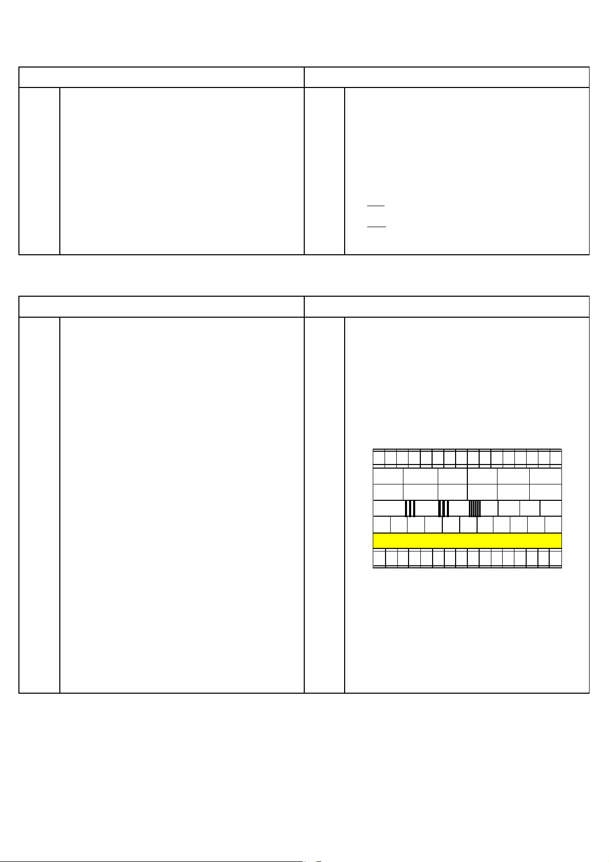
1 Turn the TV set on and heat run for 20 minutes or more. 1 Press "PICTURE" key until go to picture mode 2.
2 Horizontal size adjustment and side pin adjustment 2 The sub-brightness should be adjusted (Adjustment
should be completed. mode no. 21) using11 steps gray scale (A1-A1) of color
3 Receive Philips pattern signal. bar pattern
Set picture mode 2 as shown below. 3 Adjust until A10 is complete black and A9 is lightly black.
4 Go out from service mode.
CONTRAST : 0
COLOR : 0
BRIGHTNESS : 50
A
11
A10A
A8A7A6A5A4A3A2A
9
1
5 Adjust picture mode 2 as below.
CONTRAST : 100
COLOR : 60
BRIGHTNESS : 50
6 Press "PICTURE" key until go to picture mode 1.
- 10 -
 Loading...