

Page 1
C21-RM60
SERVICE MANUAL
PAL/SECAM/NTSC
YS
No.
C21-RM60
A Color of Cabinet Destination Code
Silver
Black
MIDDLE EAST 191
M’SIA & S’PORE 081
EROS
MIDDLE EAST
&AFRICA
EROS 192B
GA1 Chassis
192
191B
CAUTION: Before servicing this chassis, it is important that the service technician read the
"IMPORTANT SERVICE NOTES" in this Service Manual.
CONTENTS
Page
» SPECIFICATIONS ..............................................2
» IMPORTANT SERVICE NOTES .........................2
» ADJUSTMENT PRECAUTIONS.........................3
» MEMORY MAP .................................................11
» UA1 HOTEL MODE APPLICATION ................. 15
» TROUBLE SHOOTING TABLE .........................15
» CHASSIS LAYOUT ...........................................18
» BLOCK DIAGRAM ............................................19
» DESCRIPTION OF SCHEMATIC DIAGRAM ....22
» WAVEFORMS ...................................................22
» SCHEMATIC DIAGRAMS
Ë CRT UNIT......................................................23
Ë HEADPHONE UNIT ......................................23
Ë MAIN UNIT ................................................... 24
» PRINTED WIRING BOARD ASSEMBLY ..........26
» SOLID STATE DEVICE BASE DIAGRAM........ 29
» REPLACEMENT PARTS LIST ......................... 30
Ë ELECTRICAL PARTS
MAIN UNIT ................................................... 31
CRT UNIT......................................................35
HEADPHONE UNIT ......................................35
Ë SUPPLIED ACCESSORIES......................... 36
Ë PACKING PARTS ..........................................36
Ë CABINET PARTS ..........................................36
» PACKING OF THE SET ....................................37
Page
SPECIFICATIONS AND PARTS ARE SUBJECT TO CHANGE FOR IMPROVEMENT
COLOUR TELEVISION
JULY 2003 Digital Media System Group, Hitachi Asia Ltd.
Page 2

C21-RM60
2-2
qualified service personnel only.
IMPORTANT SER VICE NO TES
Maintenance and repair of this receiver should be done by
SERVICING OF HIGH VOLTAGE SYSTEM AND
PICTURE TUBE
When servicing the high voltage system, remove static charge from it by
Connecting a 10K ohm Resistor in series with an insulated wire(such as a
test probe) between picture tube dag and 2nd anode lead. (AC line cord
should be disconnected from AC outlet.)
1. Picture tube in this receiver employs integral implosion protection.
2. Replace with tube of the same type number for continued safety.
3. Do not lift picture tube by the neck.
4. Handle the picture tube only when wearing shatterproof goggles and after
discharging the high voltage completely.
X-RAY
This receiver is designed so that any X-Ray radiation is kept to an absolute
minimum. Since certain malfunctions or servicing may produce potentiall y
than 28.0kV(at beam 0 µA) for the set.
hazardous radiation with prolonged exposure at close range, the following
precautions should be observed:
2. To keep the set in a normal opeartion , be sure to make it function on
1. When repairing the circuit, be sure not to increase the high voltage to more
SECAM-B/G/DK/K1
NTSC3.58/4.43MHz (AV)
repairing, never for get to check for such high voltage after the work.
may cause excess X-ray radiation.
* If there is a possibility that the high voltage fluctuates as a result of the
24.8kV±1.5kV(at beam 1100 µA) in the case of the set. The set has been factory -
Adjusted to the above-mentioned high voltage.
3. Do not substitute a picture tube with unauthorized types and/or brands which
C1(49.75MHz) thru C12(216.25 MHz)
S1(105.25MHz) thru S36(423.25MHz)
C13(471.25MHz) thru C57(863.25MHz)
BEFORE RETURNING THE RECEIVER
Before returning the receiver to the user , perform the f ollowing safety Checks.
Depth:477.0mm
Height:475.0mm
Weight(approx):22.0kg
S37(431.25MHz) thru S41(463.25MHz)
fishpapers, cabinet backs, adjustment and compartment cover s or shields, iso-
hardware is not lodged between the chassis and other metal parts in the
receiver.
1. Inspect all lead dress to make certain that leads are not pinched or that
2. Inspect all protective devices such as non-metallic control knobs, insulating
lation resistor- capacity networks, mechanical insulator s etc.
2-1
SPECIFICATIONS
Convergence .............................................................................. Self Convergence System
Focus ....................................................................................Quadra-Potential Electrostatic
Picture IF Carrier ................................................................................................ 38.9MHz
Sweep Deflection................................................................................................... Magnetic
Intermediate Frequencies
6.5MHz .............................................................................................................32.4MHz
6.0MHz .............................................................................................................32.9MHz
5.5MHz .............................................................................................................33.4MHz
Sound IF Carrier Frequency
Colour Sub-Carrier Frequency .........................................................................34.47MHz
Power Input...................................................................................110 ~ 240V AC 50/60 Hz
Power Consumption ......................................................................................................79W
Size ............................................................................................ 6 × 12 cm Elliptic (2 pcs)
Audio Power Output Rating ........................................................................... 2.5W × 2(rms)
Voice Coil Impedance ........................................................................ 16 ohms at 400 Hz
Speaker
VHF/UHF ......................................................................................75 ohms Unbalanced
Aerial Input Impedance
Receiving System........................................................................................... PAL-B/G/DK/I
VHF-Channels .................................................... E2(48.25MHz) thru E12(224.25MHz)
Tuner Ranges
2
UHF-Channels ............................................... E21(471.25MHz) thru E69(855.25MHz)
Dimensions ..................................................................................................Width:642.0mm
Specifications are subject to change without prior notice.
Cabinet material ................................................................................................. All Plastics
Page 3

C21-RM60
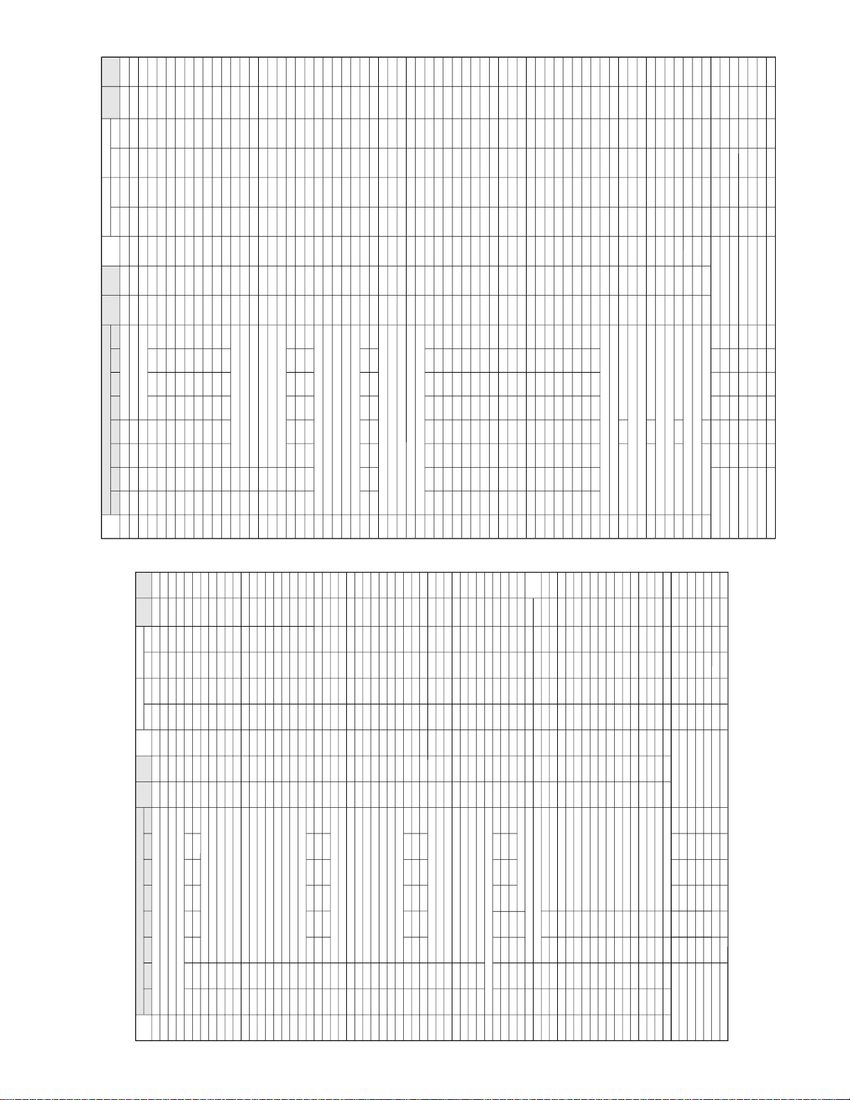
AGC &
GEOMETRIC
MODE
↓
AGC TAKE OVER POINT (AGC)
↓
VERTICAL SLOPE (V-LIN)
↓
VERTICAL AMP (V-AMP)
↓
VERTICAL SHIFT (V-CENT)
↓
HORIZONTAL SHIFT (H-CENT)
↓
EAST-WEST WIDTH (H-SIZE)
↓
HORIZONTAL PARALLELOGRAM (EW//)
↓
EAST-WEST PARABOLA/WIDTH (PARA)
↓
EAST-WEST UPPER COR. PB (COR(U))
↓
EAST-WEST LOWER COR. PB (COR(L))
↓
EAST -WEST TRAPEZIUM (TRAPE)
↓
HORIZONTAL BOW (HB)
↓
S-CORRECTION (S-COR)
WHITE POINT
ADJ.
MODE
↓
W.P RED STD. W.T. (DRI-RS)
↓
W.P. GREEN STD. W.T.(DRI-GS)
↓
W.P.BLUE STD. W.P. (DRI-BS)
↓
W.P. RED WARM W.P.(DRI-RC)
↓
W.P. GREEN WARM W.P.(DRI-GC)
↓
W.P. BLUE WARM W.P.(DRI-BC)
↓
W.P. RED COOL W.P.(DRI-RW)
↓
W.P. GREEN COOL W.P.(DRI-GW)
↓
W.P. BLUE COOL W.P. (DRI-BW)
SUB
ADJ.
MODE
↓
MAX VOLUME (SUB-VOL)
↓
SUB CONTRAST (SUB-CON)
↓
SUB COLOUR (SUB-COL)
↓
SUB BRIGHTNESS (SUB-BRI)
↓
SUB TINT (SUB-TINT)
↓
SUB SHARPNESS (SUB-SHP)
↓
MAX HOTEL VOLUME (HTL-VOL)
↓
HOTEL PROGRAM NO(HTL-PRG)
↓
OSD GRB REFERENCE (RGB)
↓
BLACK LEVEL OFFSET R(CUT-R)
↓
BLACK LEVEL OFFSET B(CUT-B)
↓
CATHODE DRIVE LEVEL(CDL)
FORWARD : CH DOWN KEY
REVERSE : CH UP KEY
* ( ) means OSD display.
FORWARD : CH DOWN KEY
REVERSE : CH UP KEY
AGC &
GEOMETRIC
MODE
WHITE POINT
ADJ.
MODE
SUB
ADJ.
MODE
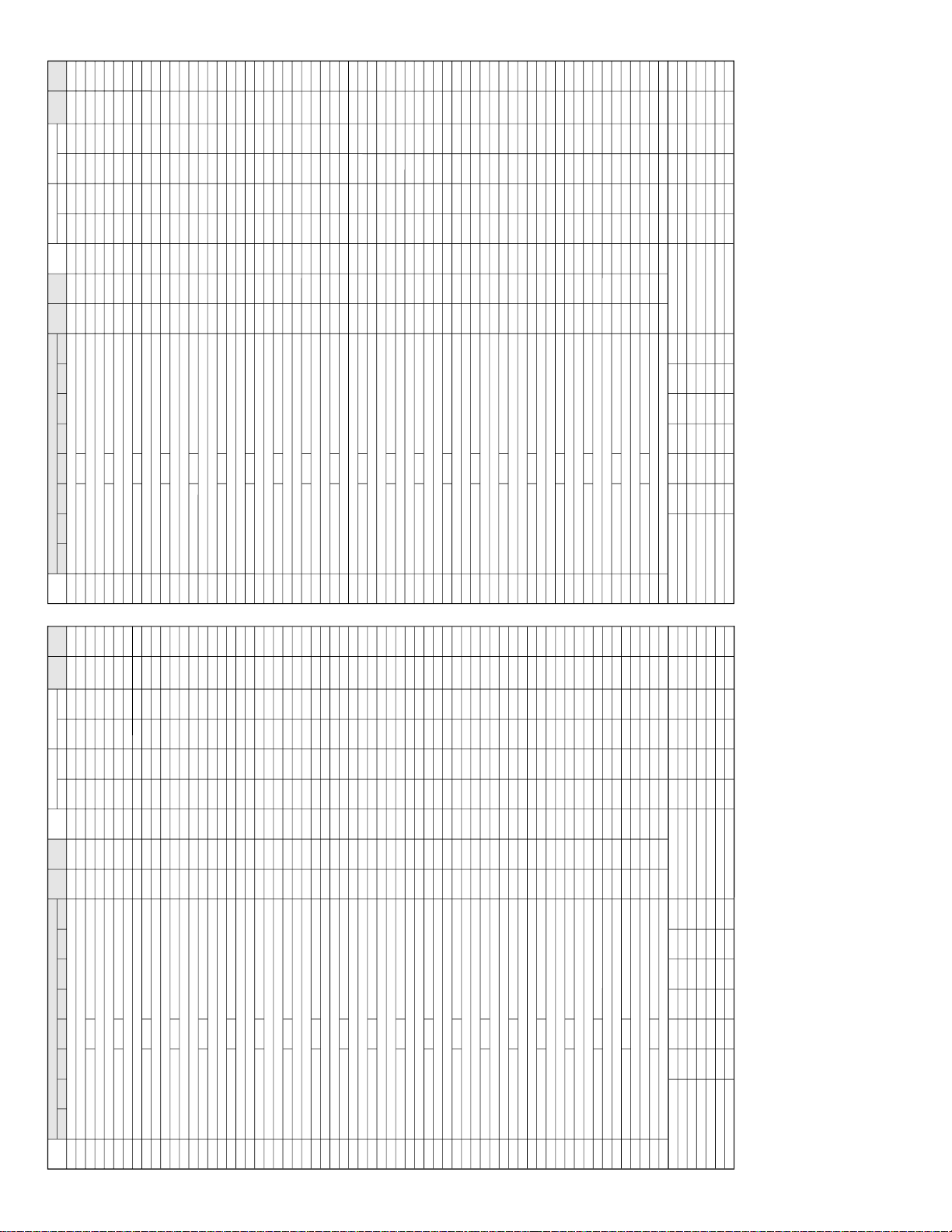
Y-DELAY
ADJ.
MODE
MISC.
OPTION
MODE
IC
OPTION
MODE
OFFSET
ADJ.
MODE
3-2
SERVICE MODE
Ë
(1)In the Service Mode, Key is used to select the mode in the following order.
C bus control
2
C bus control include
2
C bus control). (Use
2
3-1
ADJUSTMENT PRECAUTIONS
This model's setting are adjusted in two different ways: through the I
and in the conventional analog manner. The adjustments via the I
preset-only items and variable data.
CAUTION: Make sure TV Set is in "Normal Condition" before switch to Service Mode for
adjustment.
1 Short JA 137 & JA 138 for 1 second and release to switch to the service mode position,
1. Setting the service mode by the microprocessor.
and the microprocessor is in input mode. (Adjustment through the I
JWS Key to set as well).
one by one.
2 Press the CH DOWN / UP key on the remote controller to get ready to select the mode
by one.
3 Press the CH DOWN / UP key on the remote controller to select the modes re v ersibly one
4 Using the VOLUME UP/ DOWN key on the remote controller, the data can be modified.
position, and the microprocessor is in out of the service mode.
5 Short JA 137 & JA 138 for 1 second and release to switch to the normal mode (OFF)
2. Factory Presetting.
Service Mode position.Initial values are automatically preset, only when a new
EEPROM is used (Judge with the first 4 bytes ).
1 Short JA 137 & JA 138 then turn "ON" the main power and release to switch to the
3
2 The initial data are preset as listed in page 5.
3 Make sure the data need modify or not (Initial data).
Note: Once the chassis has been assembly together and ready to be POWER ON for the
FIRST TIME, make sure to short JA137 & JA138 to switch to the service mode
position first and then turn on the main power switch (See 2-1 above).
Precaution: If haven't done this initiation, it may possibly generate excessive Beam
current.
(GA1 Series type RH-IX3368CE Attachment)
3. For reference please check with memory map
Page 4
C21-RM60
Y-DELAY
ADJ.
MODE
↓
Y-D TIME FOR PAL (TV) (DL-PT)
↓
Y-D TIME FOR SECAM (TV) (DL-ST)
↓
Y-D TIME FOR N358 (TV) (DL-3T)
↓
Y-D TIME FOR N443 (TV) (DL-4T)
↓
Y-D TIME FOR B/W (TV) (DL-TV)
↓
Y-D TIME FOR PAL (AV) (DL-PA)
↓
Y-D TIME FOR SECAM (AV) (DL-SA)
↓
Y-D TIME FOR N358 (AV) (DL-3A)
↓
Y-D TIME FOR N443(AV) (DL-4A)
↓
Y-D TIME FOR B/W (AV) (DL-AV)
*(Y-D : Y-DELAY)
OFFSET
ADJ.
MODE
↓
COLOUR OFFSET (PAL) (COL-OP)
↓
COLOUR OFFSET (SECAM) (COL-OS)
↓
COLOUR OFFSET (NTSC358) (COL-O3)
↓
COLOUR OFFSET (NTSC443) (COL-O4)
↓
SHARPNESS OFFSET (PAL) (SHP-OP)
↓
SHARPNESS OFFSET (SECAM) (SHP-OS)
↓
SHARPNESS OFFSET (NTSC358) (SHP-O3)
↓
SHARPNESS OFFSET (NTSC443) (SHP-O4)
IC
OPTION
MODE
↓
VERTICAL SCAN DISABLE(VSD)
↓
BLACK STRETCH (BKS)
↓
AUTO V OLUME LEVELING(AVL)
↓
FAST FILTER IF-PLL(FFI)
↓
ENABLE VERTICAL GUARD (EVG)
↓
EHT TRACKING MODE (EHT)
↓
OVERSCAN SWITCH OFF(OSO)
↓
AUTO COLOUR LIMIT(ACL)
↓
FORCED COLOUR LIMIT(FCO)
MISC.
OPTION
MODE
↓
SOUND SYSTEM M (S-M)
↓
SOUND SYSTEM DK (S-DK)
↓
SOUND SYSTEM I (S-I)
↓
SOUND SYSTEM BG (S-BG)
↓
PLAYBACK SECAM (P-SECAM)
↓
FE (RF) NTSC 3.58 (F-N358)
↓
FE (RF) NTSC 4.43 (F-N443)
↓
FE (RF) SECAM (F-SECAM)
↓
VIDEO MUTE AT IDENT LOSS (VMI)
↓
VIDEO MUTE AT PROGRAM
/SOURCE CHANGE (VMC)
↓
HOTEL MODE (HTL)
↓
REDUCED FM DEMODULATION
GAIN FOR BTSC SIGNAL (BTSC)
↓
A
A
↓
NUMBER OF EXT AV SOURCE (AV)
↓
FM WINDOW SELECTION (FMWS)
↓
SOUND MUTE BIT 0 (SM0)
↓
SOUND MUTE BIT 1 (SM1)
↓
THAI LANGUAGE (THA)
↓
ARABIC LANGUAGE (ARA)
↓
MALAY LANGUAGE (MAL)
↓
CHINESE LANGUAGE (CHI)
↓
FRENCH LANGUAGE (FRE)
↓
RUSSIAN LANGUAGE (RUS)
↓
FORCED V-SYNC SLICING LEVEL(FSL)
↓
SYNC OF OSD (HP2)
↓
TUNER SELECTION (CPT)
↓
B
↓
BILINGUAL(BIL)
↓
IF AGC SPEED BIT 0 (AGC0)
↓
IF AGC SPEED BIT 1 (AGC1)
↓
FOA Time Constant-RF (FOA-FE)
↓
FOB Time Constant-RF (FOB-FE)
↓
FOA Time Constant-AV (FOA-AV)
↓
FOB Time Constant-AV (FOB-AV)
↓
LED BLINK SPEED (LED-F)
↓
VOLUME CONTROL TABLE (MSA)
↓
OUTPUT VERTICAL GUARD (NDF)
B
4-2
FUNCTION AGC
RC COMMAND SERVICE-ITEM
CONTRAST DOWN V-LIN
* Direct Key-in for service item in service mode
TINT DOWN H-CENT
COLOUR DOWN V-AMP
SHARPNESS DOWN EW / /
BRIGHTNESS DOWN V-CENT
TIMER SUB-VOL
SYSTEM HB
BLUEBACK S-COR
CONTRAST UP SUB-CON
TINT UP SUB TINT
COLOUR UP SUB-COL
BRIGHTNESS UP SUB-BRI
SHARPNESS UP SUB-SHP
4-1
4
Page 5
REMARK
INITIAL DATA FIX/ADJ
C21-RM60
5-2
BTSC 0(DISABLE)/1(ENABLE) 0 *FIX
EEPROM ITEMS OSD DATA LENGTH
SHARPNESS OFFSET (NTSC443) SHP-O4 0~15 8 *FIX
VERTICAL SCAN DISABLE VSD 0(DISABLE)/1(ENABLE) 0 *FIX
BLACK STRETCH BKS 0(DISABLE)/1(ENABLE) 1 *FIX
AUTOMATIC VOLUME LEVELING AVL 0(DISABLE)/1(ENABLE) 1 *FIX
FAST FILTER IF-PLL FFI 0(DISABLE)/1(ENABLE) 0 *FIX
ENABLE VERTICAL GUARD (RGB BLANKING) EVG 0(DISABLE)/1(ENABLE) 1 *FIX
EHT TRACKING MODE (HCO) EHT 0(DISABLE)/1(ENABLE) 1 *FIX
OVERSCAN SWITCH OFF OSO 0(DISABLE)/1(ENABLE) 0 *FIX
AUTO COLOUR LIMIT ACL 0(DISABLE)/1(ENABLE) 0 *FIX
REMARK
INITIAL DATA FIX/ADJ
FORCED COLOUR LIMIT FCO 0(DISABLE)/1(ENABLE) 0 *FIX
SOUND SYSTEM M S-M 0(DISABLE)/1(ENABLE) 0 *FIX
SOUND SYSTEM DK S-DK 0(DISABLE)/1(ENABLE) 1 *FIX
SOUND SYSTEM I S-I 0(DISABLE)/1(ENABLE) 1 *FIX
SOUND SYSTEM BG S-BG 0(DISABLE)/1(ENABLE) 1 *FIX
PLAYBACK SECAM P-SECAM 0(DISABLE)/1(ENABLE) 1 *FIX
FE (RF) NTSC 3.58 F-N358 0(DISABLE)/1(ENABLE) 0 *FIX
FE (RF) NTSC 4.43 F-N443 0(DISABLE)/1(ENABLE) 1 *FIX
FE (RF) SECAM F-SECAM 0(DISABLE)/1(ENABLE) 1 *FIX
VIDEO MUTE AT IDENT LOSS VMI 0(DISABLE)/1(ENABLE) 1 *FIX
VIDEO MUTE AT PROGRAM/SOURCE CHANGE VMC 0(DISABLE)/1(ENABLE) 1 *FIX
HOTEL MODE HTL 0(DISABLE)/1(ENABLE) 0 *FIX
REDUCED FM DEMODULATOR GAIN FOR BTSC SIGNAL
NUMBER OF EXTERNAL AV SOURCE AV 0 FOR1 AV/1 FOR 2AV 1 (0) *FIX
FM WINDOW SELECTION FMWS 0(DISABLE)/1(ENABLE) 0 *FIX
SOUND MUTE BIT 0 SM0 0(DISABLE)/1(ENABLE) 1 *FIX
SOUND MUTE BIT 1 SM1 0(DISABLE)/1(ENABLE) 0 *FIX
SAME AS (DRI-BS) DATA
THAI LANGUAGE THA 0(DISABLE)/1(ENABLE) 0 *FIX
ARABIC LANGUAGE ARA 0(DISABLE)/1(ENABLE) 1 *FIX
MALAY LANGUAGE MAL 0(DISABLE)/1(ENABLE) 1 *FIX
CHINESE LANGUAGE CHI 0(DISABLE)/1(ENABLE) 1 *FIX
FRENCH LANGUAGE FRE 0(DISABLE)/1(ENABLE) 1 *FIX
RUSSIAN LANGUA GE RUS 0(DISABLE)/1(ENABLE) 1 *FIX
FORCED V-SYNC SLICING LEVEL FSL 0(DISABLE)/1(ENABLE) 0 *FIX
SYNC OF OSD HP2 0(DISABLE)/1(ENABLE) 0 *FIX
TUNER SELECTION (0:SHARP/ALPS;1:MURATA) CPT 0(DISABLE)/1(ENABLE) 0 *FIX
BILINGUAL BIL 0(DISABLE)/1(ENABLE) 0 *FIX
IF AGC SPEED BIT 0 AGC0 0(DISABLE)/1(ENABLE) 1 *FIX
IF AGC SPEED BIT 1 AGC1 0(DISABLE)/1(ENABLE) 0 *FIX
PHI-1 TIME CONSTANT (RF) FOA-FE 0(DISABLE)/1(ENABLE) 0 *FIX
PHI-1 TIME CONSTANT (RF) FOB-FE 0(DISABLE)/1(ENABLE) 0 *FIX
PHI-1 TIME CONSTANT (OFF AIR) FOA-AV 0(DISABLE)/1(ENABLE) 1 *FIX
PHI-1 TIME CONSTANT (OFF AIR) FOB-AV 0(DISABLE)/1(ENABLE) 1 *FIX
LED BLINK SPEED LED_F 0(DISABLE)/1(ENABLE) 0 (1) *FIX
VOLUME CONTROL PWM TABLE MSA 0(DISABLE)/1(ENABLE) 0 (1) *FIX
OUTPUT VERTICAL GUARD NDF 0(DISABLE)/1(ENABLE) 0 (1) *FIX
NOTE :
COLOUR OFFSET (PAL) COL-OP : 8 ------> 14
COLOUR OFFSET (SECAM) COL-OS : 8 ------> 14
Please set the EEPROM initial data according to the value in parenthesis ( ) before adjustment.
2) *1: S-COR ADJUST=20
3) *2: CDL ADJUST=7
1) *FIX: PLEASE DO NOT CHANGE FIXED DATA WITHOUT SPECIFIC INSTRUCTION.
COLOUR OFFSET (NTSC358) COL-O3 : 4 ------> 10
COLOUR OFFSET (NTSC443) COL-O4 : 4 ------> 10
4) *3: ADJUST COLOUR OFFSET AFTER ADJUST SUB-COLOUR
5-1
After short JA137& JA138, and turn on the main power switch, read data from EEPROM
address 00H ~ 03H, and compare to the list below, if different, initialize the EEPROM.
00H: 55H 02H: 43H
Address Data Address Data
01H: 4FH 03H: A1H
EEPROM ITEMS OSD DATA LENGTH
AGC TAKE OVER POINT AGC 0~63 14 ADJ
VERTICAL SLOPE V-LIN 0~63 32 ADJ
VERTICAL AMPLITUDE V-AMP 0~63 32 ADJ
VERTICAL SHIFT V-CENT 0~63 32 ADJ
HORIZONTAL SHIFT H-CENT 0~63 32 ADJ
EAST-WEST WIDTH H-SIZE 0~63 32 *FIX
HORIZONTAL PARALLELOGRAM EW// 0~63 32 *FIX
EAST-WEST PARABOLA/WIDTH PARA 0~63 32 *FIX
EAST-WEST UPPER CORNER PARABOLA COR (U) 0~63 32 *FIX
EAST-WEST LOWER CORNER PARABOLA COR (L) 0~63 32 *FIX
EAST -WEST TRAPEZIUM TRAPE 0~63 32 *FIX
HORIZONTAL BOW HB 0~63 32 *FIX
S-CORRECTION S-COR 0~63 0 CHG *1
WHITE POINT RED STD WHITE TEMP DRI-RS 0~63 32 *FIX
WHITE POINT GREEN STD WHITE TEMP DRI-GS 0~63 32 ADJ
WHITE POINT BLUE STD WHITE TEMP DRI-BS 0~63 32 ADJ
WHITE POINT RED COOL WHITE TEMP DRI-RC 0~63 25 ADJ
WHITE POINT GREEN COOL WHITE TEMP DRI-GC 0~63 32 ADJ (DRI-GS)-7 DA T A
WHITE POINT BLUE COOL WHITE TEMP DRI-BC 0~63 32 ADJ
WHITE POINT RED W ARM WHITE TEMP DRI-RW 0~63 32 *FIX
WHITE POINT GREEN W ARM WHITE TEMP DRI-GW 0~63 32 ADJ (DRI-GS)-7 DATA
WHITE POINT BLUE W ARM WHITE TEMP DRI-BW 0~63 32 ADJ (DRI-BS)-7 DA TA
MAX VOLUME SUB-VOL 0~63 63 *FIX
SUB CONTRAST SUB-CON 0~63 63 *FIX
SUB COLOUR SUB-COL 0~63 32 ADJ
SUB BRIGHTNESS SUB-BRI 0~63 32 ADJ
SUB TINT SUB-TINT 0~63 32 ADJ
SUB SHARPNESS SUB-SHP 0~63 32 (20) *FIX
MAX HOTEL VOLUME HTL-VOL 0~63 32 *FIX
HOTEL PROGRAM NUMBER HTL-PRG 0~99 OR>99FOR NONE 255 *FIX
OSD GRB REFERENCE RGB 0~15 15 *FIX
BLACK LEVEL OFF-SET R CUT-R 0~63 32 ADJ
BLACK LEVEL OFF-SET G CUT-G 0~63 32 ADJ
CATHODE DRIVE LEVEL CDL 0~15 0 CHG *2
Y-DELAY TIME FOR PAL(TV) [YD] DL-PT 0~15 12 *FIX
Y-DELAY TIME FOR SECAM(TV) [YD] DL-ST 0~15 15 *FIX
Y-DELAY TIME FOR N358 (TV) [YD] DL-3T 0~15 12 *FIX
Y-DELAY TIME FOR N443 (TV) [YD] DL-4T 0~15 12 *FIX
Y-DELAY TIME FOR B/W (TV) [YD] DL-TV 0~15 12 *FIX
Y-DELAY TIME FOR PAL (AV) [YD] DL-PA 0~15 12 *FIX
Y-DELAY TIME FOR SECAM (AV) [YD] DL-SA 0~15 15 *FIX
Y-DELAY TIME FOR N358 (AV) [YD] DL-3A 0~15 12 *FIX
Y-DELAY TIME FOR N443 (AV) [YD] DL-4A 0~15 12 *FIX
Y-DELAY TIME FOR B/W (AV) [YD] DL-AV 0~15 12 *FIX
COLOUR OFFSET (PAL) COL-OP 0~15 8 CHG *3
COLOUR OFFSET (SECAM) COL-OS 0~15 8 CHG *3
COLOUR OFFSET (NTSC358) COL-O3 0~15 4 CHG *3
COLOUR OFFSET (NTSC443) COL-O4 0~15 4 CHG *3
SHARPNESS OFFSET (PAL) SHP-OP 0~15 8 *FIX
SHARPNESS OFFSET (SECAM) SHP-OS 0~15 4 *FIX
SHARPNESS OFFSET (NTSC358) SHP-O3 0~15 12 (8) *FIX
5
Page 6
C21-RM60
PROM follow by INITIAL setting.
2
6-2
ITEMS DATA SETTING
LAST PROGRAM/CHANNEL 1
FLASHBACK PROGARM/CH 1
DIGIT 1
C-SYSTEM AUTO
VOLUME 1
S-SYSTEM *1
AFC ON
SKIP OFF
COLOUR (CENTER)
CONTRAST (MAX)
TINT (CENTER)
SHARPNESS (CENTER)
BRIGHTNESS (CENTER)
WHITE TEMP ST ANDARD
REMINDER TIMER In-active, "--:--"
ON TIMER In-active, "--:--"
OFF TIMER In-active, "--:--"
LAST POWER POWER-ON
LANGUAGE *1
BLUE BACK MUTE ON
HOTEL MODE OFF
LAST TV/AV TV
0 CHANNEL SKIP ON
SHIPPING SETTING & CHECKING
selected.
(1)The following default data has been factory-set for the E
3 ENGLISH B/G
INITIAL LANGUAGE SOUND SYSTEM
*1:Please refer defaults for LANGUAGE and SOUND SYSTEM per MODEL as follows.
"30,000" "20,000" 12300K ENGLISH B/G 6
MIDDLE EAST
DESTINATION MAGNETIC FIELD (V, H) nT BACKGROUND LANG. S-SYS LANG QTY
FACTORY SETTING BY MODEL
(Reference: Geomagnetism Adjustment)
"-10,000" "40,000" 12300K ENGLISH B/G 6
(191)
M’SIA & S’PORE
"-10,000" "40,000" 12300K ENGLISH B/G 6
(081)
AFRICA (191B)
MIDDLE EAST&
EROS (192) "30,000" "20,000" 12300K ENGLISH B/G 6
EROS (192B) "-10,000" "40,000" 12300K ENGLISH B/G 6
LANGUAGE QTY: ENGLISH/CHINESE/FRENCH/ARABIC/MALAY/RUSSIAN
MCL1
0 41.10
CH-NO Fv (MHz) SOUND SYS
INITIAL SHIPPING SETTING FOR PRESET TUNING
(1)Please set the MCL1.
(2)After set the MCL1, please set the INITIAL SETTING for each model.
INITIAL 3: Singapore/M.East/Africa/EROS and malaysia models.
1 48.25 B/G
2 62.25 B/G
3 77.25 D/K
4 175.25 B/G
5 182.25 B/G
6 183.25 D/K
7 191.25 D/K
8 196.25 B/G
6-1
9 199.25 M
10 210.25 B/G
11 224.25 B/G
12 471.25 B/G
13 487.25 I
14 503.25 B/G
15 575.25 B/G
16 583.25 B/G
17 599.25 B/G
18 621.25 M
19 639.25 D/K
20 703.25 B/G
21 735.25 I
22 767.25 B/G
23 815.25 B/G
24 855.25 I
25 855.25 B/G
26 55.25 M
27 83.25 M
28 183.25 M
29 193.25 M
30 217.25 M
31 471.25 M
32 477.25 M
33 693.25 M
34 41.10
35 112.25 B/G
36 168.25 B/G
37 41.10
38 294.25 B/G
39 463.25 B/G
40 41.10
41 647.25 B/G
42 663.25 B/G
43 679.25 B/G
44 174.95 B/G
45 175.55 B/G
46 41.10
INITIAL key.
* The Sound System of above channels will be changed accordingly, after pressing
For example; pressing INITIAL3, all Sound Systems will be set to B/G.
6
Page 7
C21-RM60
» Bias box: About 4.5 V
Oscilloscope
0.1V
TV Set
Bias box
TP201+
+
—
—
E-9 CH
P C
10k
100k
1n60
75ohm
IF OUT
-1.5+/-0.8dB
1000p
Oscilloscope
a
b
A
B
A
B
A = B
A = B
Rank "A"
(on the right of the CRT)
Rank "A"
(on the left of the CRT)
Green-only
Blue-only
Red-only
Signal-colour
screen cleared
Fig. 4-1
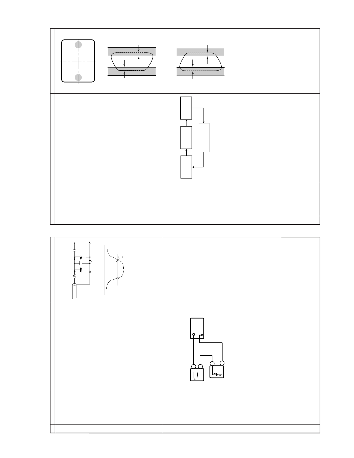
PURITY ADJUSTMENT
the beam current to about 700 µA.
coil.
2. Degauss the CRT enough with the degausing
1. Receive the GREEN-ONLY signal. Adjust
PURITY ADJ.
1
NO. Adjustment part Adjusting procedure and conditions Waveform and others
netic field and keep the static convergence
roughly adjusted.
adjust the magnetic field.
Note: Follow the Job Instruction Sheet to
3. Maintain the purity magnet at the zero mag-
through the microscope. Adjust the landing to
the rank A requirements.
4. Observe the points a, b as shown in Fig. 4-1
5. Orient the raster rotation to 0 eastward.
warming up the unit for 30 minutes
» Tightening torque: 108 ± 20 N (11 ± 2 kgf)
A rank requirements. If not, stick the magnet
sheet to correct it.
6. Tighten up the deflection coil screws.
Note:This adjustment must be done after
7. Make sure the CRT corners landing meet the
or longer with a beam current over
700 µA.
Fig. 4-2
* For the following colours press R/C RGB key to
Fig. 4-3
7-2
change.
PIF ADJUSTMENT
signal,but with no signal input.
to the tuner antenna. ( RF SWEEP )
Adjust the PLL data.
2.Connect the sweep generator's output cable
3.Adjust the sweep generator's to 80dBuV.
4. Connect the response lead ( use LOW IM-
NO. Adjustment part Adjusting procedure and conditions Waveform and others
1.Get the tuner ready to receive the CH. E - 9
Tuner IFT
(PRESET)
1
Fig. 1
PEDANCE probe with wave detector ; see
Fig.1 ) to the tuner's IF output terminal.
nected ).
( This terminal must have the probe alone con-
5.Set the RF AGC to 0 - 6 V with no saturation
Fig. 2
For the 50 ohm signal strength
gauge, when not using 50/75
impedance adapter, signal
strength is 52 ±1 dBµV(75 ohm
open), instead of 57±1 dBµV
(75 ohm open).
The loss of using impedance
Note:
adapter
Precaution:
7-1
Fig. 3
as shown in Fig. 2.
Be sure to keep the tuner cover in position
Note:
AGC Terminal) as shown in Fig. 3.
» Signal Strength: 57 ±1 dBµV (75 ohm open)
1. Receive "PAL COLOUR BAR" signal.
2. Connect the oscilloscope to TP201 (Tuner’s
C BUS
RF-AGC
2
TAKE OVER
POINT
ADJUSTMENT
(I
CONTROL)
"AGC" bus data to obtain the Tuner output pin
drop 0.1 V below maximum voltage.
63~67dBµV , and make sure there is no noise .
3. Call "AGC" mode in service mode. Adjust the
sure that there is no cross modulation beat.
4. Change the antenna input signal to
5. Turn up the input signal to 90~95 dBµV to be
with the waveform.
6.Adjust the tuner IF coil to obtain the waveform
during this adjustment.
2
7
Page 8
C21-RM60
t
3.2Vdc
0
RGB
BGR
R
G
B
R
G
B
B
G
R
B
G
R
RGB
BGR
Lacquer
Wedge "a"
Wedge
"b"
Wedge
"c"
About
100°
About
100°
4-pole magnet
6-pole magnet
CRT neck
Lacquer
Purity magnet
20mm
1 2 3 4 5
1 2 3 4 5
* Alternative Procedure:
(1) Step (1), (2), (3) and (4) are same
line appear and make sure the col-
as beside procedure.
(2) Then continue adjust until retrace
our appear whether red, green or
blue.
test points as below which is based
on colour appear at (2) RED =
TP47R, GREEN = TP47G, BLUE =
TP47B.
(3) Connect the oscilloscope to related
of signal reach 3.2Vdc.
(4) Then adjust Screen VR until the tip
1
2
Line 3 is one step (data) brighter than line 2
Y : 0.275
# 12300°K X : 0.272
(MINOL T A COLOUR ANALYZER CA-
100)
*Note: Above Data can be UP/DO WN
DRI-BW="DRI-BS"-7
DRI-GC="DRI-GS"-5
LOW HIGH
10cd/m2 120cd/m2
by V olume key .
DRI-RC=25
* 12300°K DRI-GW="DRI-GS"-7
8-2
k
hatch pattern with 5 black level windows)
the line 1and 2 have the same darkness wherelse
line 3 is one step (data) brighter than line 2. Fi-
nally data minus 1 to make line 1, 2, and 3 are in
DRI-RS/RW/RC, DRI-GS/GW/GC, DRI-BS/BW/
BC,
CUT-R and CUT-G must be INITIAL DATA.
room.
NO VIDEO signal.
tor.
crease screen variable resistor until colour raster
suddenly on and off (AKB start function).
tor until screen retrace line cut off. (Not Raster)
Must confirm the AKB function in set before con-
tinue the next adjustment.
1. Before CRT cutoff adjustment, SUB-BRIGHT,
Remar
CRT CUTOFF
CRT CUT-OFF, BACKGROUND AND SUB-CONTRAST ADJUSTMENT
1
NO. Adjustment part Adjusting procedure and conditions Waveform and others
2. CRT Cutoff adjustment must be done inside a dark
C BUS
2
ADJUSTMENT
(I
CONTROL)
1. Switch TV to VIDEO mode,BLUE BACK OFF, with
Fig. 5-1
2. Press R/C to set Picture Normal condition.
3. First, off the screen by adjust screen variab le resis-
*4. Next, checking AKB circuit function by slowly in-
5. Then continue adjust until retrace line appear.
6. Finally, slowly decrease the screen variable resis-
Fig. 5-2
Note :
1. Call " SUB-BRI" in service mode. (Receive Cross-
SUB-
BRIGHTNESS
2
Fig. 5-3
same level (darkness).
2. Adjust the " SUB BRIGHT " bus data in order that
ADJUSMENT
3. Clear the SERVICE mode.
C BUS
2
(I
CONTROL)
) TP603 (+).
DRI-BS data to have a colour temperature of
12300°K ( white ). * Note .
and set BRIGHTNESS Y b y generator, to **10 cd/
m2 (MINOL TA CA-100) by reducing LUMINANCE
Y signal.
temperature #. Then go back NORMAL mode
(HIGH BRIGHT) to check colour temperature. If
1. Receive the "WHITE" pattern with BURST signal.
2. Press R/C to set Picture NORMAL condition.
3. Connect the DC miliammeter between TP602 (-
4. Check Beam current should be around 1100 µA.
5. Set it to service mode and adjust the DRI-GS, &
6. Receive "WHITE" pattern, WITH BURST signal,
C BUS
BALANCE
SERVICE
MODE ADJ
2
CONTROL)
(I
WHITE
out of range, back to (1).
7. Adjust "CUT-R" & "CUT-G" to get desired colour
3
Fig. 5-4
ing up the unit for 30 minutes or longer with
a beam current over 700µA.
DATA, after finishing DRI-BS and DRI-GS DATA
ADJUSTMENT.
* ADJUST DRI-GC/GW, DRI-BC/BW as following
DRI-RW = 32 (FIXED), DRI-RS = 32 (FIXED)
Note:This adjustment must be done after warm-
DRI-BC = "DRI-BS"
& TP602 (–).
(Full Scale: 3 mA Range)
1. Receive the "Monoscope Pattern" signal.
2. Press R/C to set Picture NORMAL condition.
3. Connect the DC miliammeter between TP603 (+)
4. Beam current must be within 1100 ± 100 µA.
Maximum
beam check
4
8-1
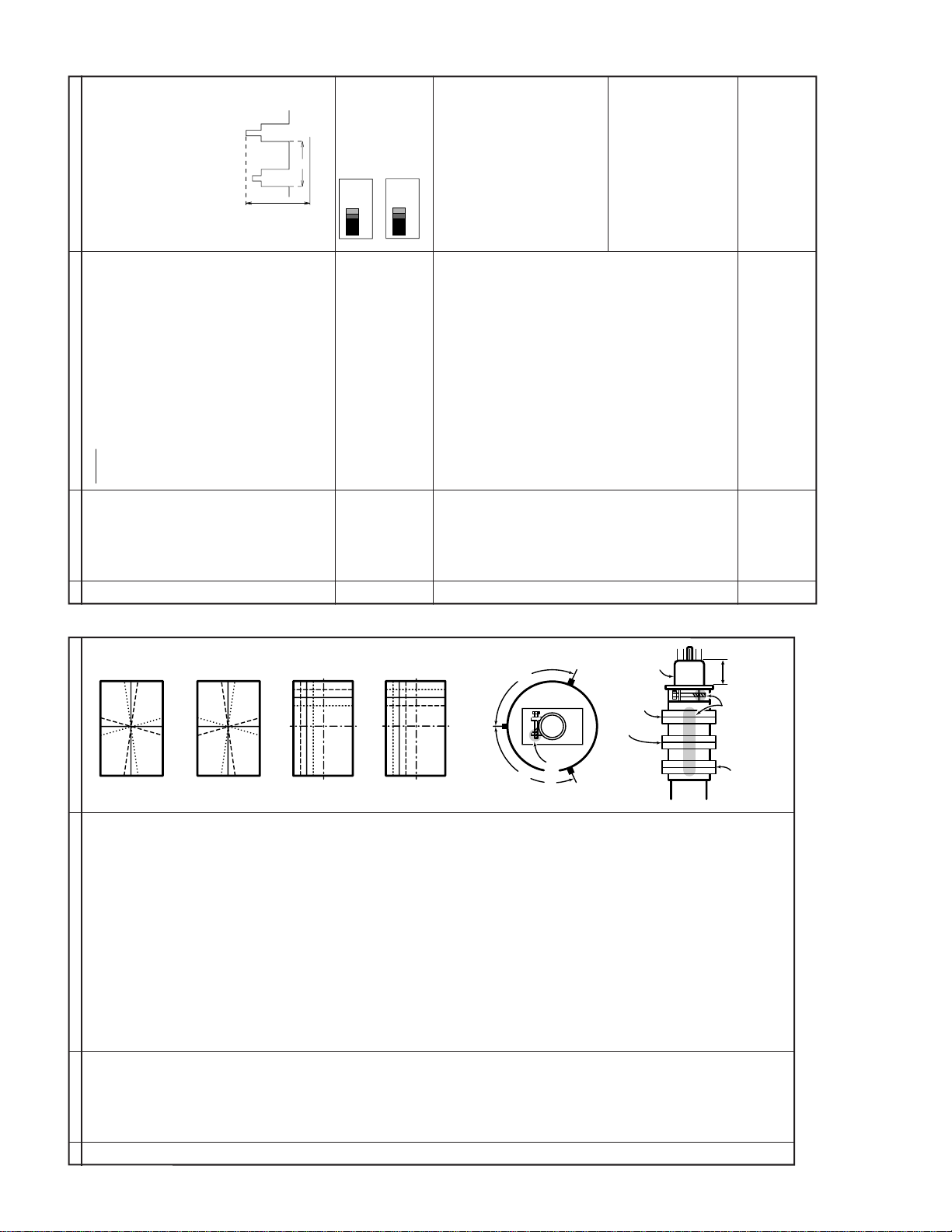
1. Receive the "Crosshatch Pattern" signal.
2. Using the remote controller, call NORMAL
CONVER-
GENCE ADJ.
1
NO. Adjustment part Adjusting procedure and conditions Waveform and others
mode.
(To be done
CONVERGENCE ADJUSTMENT
angle in order to superpose the blue and red
colours.
angle in order to superpose the green colour
STATIC CONVERGENCE
over the blue and red colours.
1. Turn the 4-pole magnet to a proper opening
2. Turn the 6-pole magnet to a proper opening
after the purity
adjustment.)
screen in the following steps.
DYNAMIC CONVERGENCE
1. Adjust the convergence on the fringes of the
a) Fig. 5-1: Drive the wedge at point "a" and
swing the deflection coil upward.
b) Fig. 5-2: Drive the wedge at points "b" and "c"
and swing the deflection coil downward.
swing the deflection coil rightward.
swing the deflection coil leftward.
c) Fig. 5-3: Drive the "c" wedge deeper and
d) Fig. 5-4: Drive the "b" wedge deeper and
2. Fix all the wedges on the CRT and apply glass
screw, magnet unit (purity, 4-pole, 6-pole
magnets) and magnet unit lock screw.
tape over them.
3. Apply lacquer to the deflection yoke lock
8
Finally received the Red-only and Blue-only
signals to make sure there is no other colours
on the screen.
Page 9
Cy
G
B
W
Y 100%W
75%
Mg R
5) BLUE-OUT.
W
Y
Cy G Mg R
B
SAME LEVEL
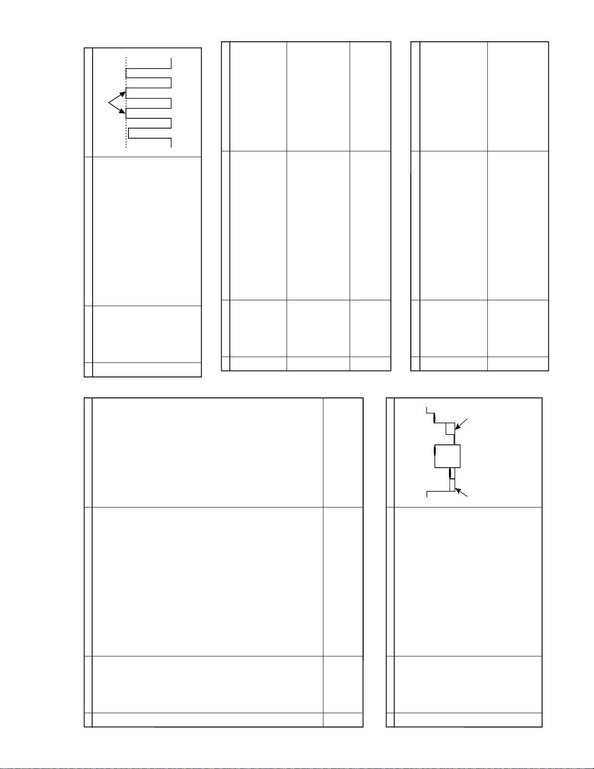
NTSC CHROMA ADJUSTMENT
thru AV in.
1. Receive the "NTSC 3.58 Colour Bar" signal
10:1)
» Range : 100mV/div. (AC)(Use Probe
» Sweep time : 10 µsec/div.
2. Connect the oscilloscope to TP47B (P882 pin
3. Call the "SUB-TINT" mode in ser vice mode.
Adjust the "SUB-TINT" bus data to obtain the
waveform shown as Fig. 7-1.
4. Clear the SERVICE mode.
Fig. 7-1
each short test.
* Select one of Q883/5/7 to do
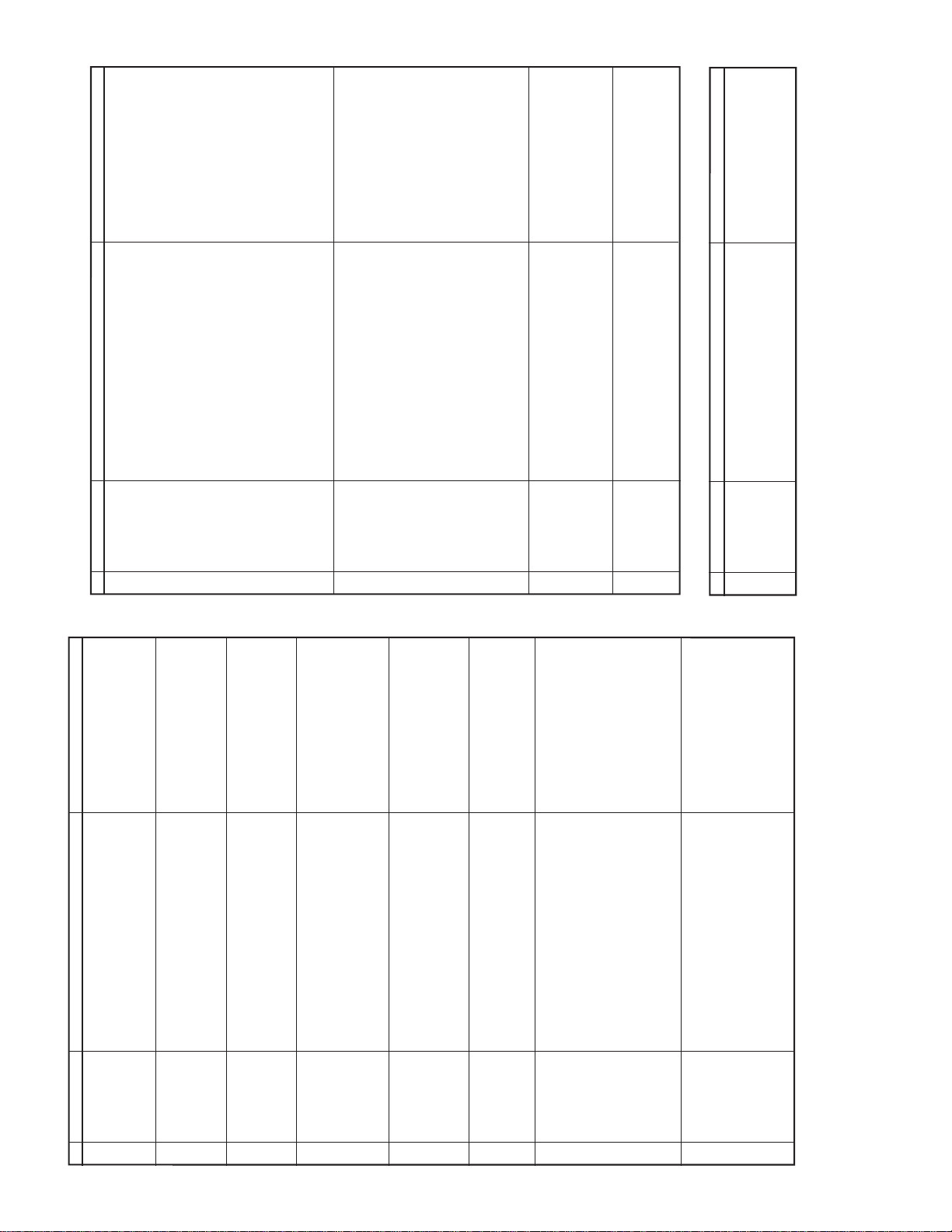
1. Receive "Monoscope Pattern" signal.
2. Set CONTRAST MAX.
PROTECTOR OPERATION CHECKING
the protector is not working.
3. Set voltage of Bias Box to 18V and mak e sure
the protector is working.
4. Set voltage of Bias Box to 27V, and make sure
1. Once finish rectified Electrolytic Capacitor short
short, make sure the protector ON and switch
to standby mode.
3. Set BRIGHT MAX.
4. Dur ing the Collector & Emitter of Q883/5/7
(R610 side).
1. Receive "Monoscope Pattern" signal.
2. Connect output of Bias Box to D603 cathode
testing in +B line, check all possible damaged
components on +B line.
(Use random selected set for inspection)
C21-RM60
Note:
Front AV prlority check, please
connect
Front Audio (L) In or Front Au-
dio (L)/(R).
9-2
make sure that the modes change in order of
White Colour Bar, Sound 400 Hz 100% Mod).
pedance. Make sure the output is as speci-
fied (1.0 Vp-p ±3 dB).
impedance. Make sure the O/P is as speci-
1. Receive the "PAL Colour Bar" signal (100%
2. Terminate the Video output with a 75 ohm im-
fied (1.76 Vp-p ±3 dB).
3. Terminate the Audio output with a 10k ohm
TV, AV & TV again and the video & audio out-
put are according to the input terminal for each
mode.If connect input to Front and Rear AV
terminal, input terminal of Front AV will be se-
1. Using the TV/AV key on the remote controller,
lected.
A/V INPUT AND OUTPUT CHECKING
SUB-TINT
1
NO. Adjustment part Adjusting procedure and conditions Waveform and others
C BUS
2
CONTROL)
(I
NO. Adjustment part Adjusting procedure and conditions Waveform and others
BEAM
PROTECTOR
1
H. V PROTEC-
TOR
2
Other
protectors
3
VIDEO AND
AUDIO OUT-
1
NO. Adjustment part Adjusting procedure and conditions Waveform and others
PUT CHECK
VIDEO AND
AUDIO INPUT
CHECK
2
Fig. 6-1
9-1
to set overscan of 9.5% typical.
till the horizontal line in the center of
monoscope is just at the position where the
1. Receive Monoscope Pattern Signal.
2. Call the "V-LIN" mode.
C BUS
2
V-LIN
(I
1
NO. Adjustment part Adjusting procedure and conditions Waveform and others
HORIZONTAL AND VERTICAL DEFLECTION LOOP ADJUSTMENT
blanking starts.
3. Increase or decrease "V-LIN" by Volume key
CONTROL)
till the picture is centered.
1. Call the "V-CENT" mode.
2. Increase or decrease "V -CENT" by V olume key
C BUS
2
V-CENTER
(I
CONTROL)
2
1. Call the "V-AMP" mode.
2. Increase or decrease "V -AMP" by V olume key
C BUS
2
V-AMP
(I
3
CONTROL)
Adjustment Spec 9.5% range +1% -0%.
key to center the picture horizontal.
1. Call the "H-CENT" mode.
2. Increase or decrease "H-CENT" by Volume
C BUS
2
H-CENTER
(I
CONTROL)
4
re-adjust V-Slope, V-Shift and V-Amp to
1. SET DATA TO 20.
* Check the E-5 CH Monoscope Pattern then
C BUS
2
S-CORREC-
TION (I
5
makesure adjustment is in acceptable Ring-
Shaped.
CONTROL)
1. Receive the "Monoscope Pattern" signal.
1. SET DATA TO 20.
SUB-
SHARPNESS
1 Focus
6
9
PAL CHROMA ADJUSTMENT
ing.
2. Press R/C to set Picture NORMAL condition.
3. Adjust the focus control to get the best focus-
NO. Adjustment part Adjusting procedure and conditions Waveform and others
Red cathode(O882 Cathode).
1. Receive the "PAL Colour Bar" signal.
2. Press R/C to set Picture Normal condition.
C BUS
2
SUB COLOUR
(I
1
probe)
3. Connect the oscilloscope to
» Range : 20 V/div. (AC) (Using 10:1
» Sweep time : 10 µsec/div.
4. Using the R/C call "SUB COL" in SERVICE
CONTROL)
mode. Adjust SUB COLOUR b us data, so that
the 75% White & Red portions of PAL Color
Bar be at the same level shown as Fig. 6-1.
Before adjust SUB-COL, make sure COL-
OP=8, COL-OS=8, COL-03=4, COL-04=4.
set.
COL-OP : 8 ------> 14 COL-O3 : 4 ------> 10
COL-OS : 8 ------> 14 COL-O4 : 4 ------> 10
5. After adjust SUB-COLOUR, change colour off
6. Clear the SERVICE mode.
Page 10
C21-RM60
(Continued)
press the COLOUR SYSTEM key to select
modes except P AL, chec k the COLOUR is not
working properly. Then, select the "P AL" mode.
Check again its colour so that it is working
properly.
press COLOUR SYSTEM key to select modes
except SECAM, check the COLOUR is not
working properly. Then, select the "SECAM"
1. Receive the "PAL COLOUR BAR" signal,
2. Receive "SECAM COLOUR BAR" signal,
mode. Chec k again its colour so that it is work-
SYSTEM" to select B/G, I. Check the sound
output is not working properly. Select D/K and
check the sound output to make sure it is work-
ing properly.
signal thru AV, press COLOUR SYSTEM key
to select modes except N4.43/3.58, check the
COLOUR is not working properly. Then, se-
lect the "NTSC 4.43/3.58" mode. Chec k again
its colour so that it is working properly.
3. Receive "NTSC 4.43/3.58 COLOUR BAR"
1. Receive "P AL-D/K" signal, press the "SOUND
ing properly.
2. Receive "PAL-I" signal, press the "SOUND
SYSTEM" to select B/G, D/K. Check the sound
output is not working properly. Select I and
check the sound output to make sure it is
working properly.
sure the sound is heard from the speakers.
SYSTEM" to select I, D/K. Check the
sound output is not working properly. Select
B/G and check the sound output to make sure
3. Receive "P AL-B/G" signal, press the "SOUND
it is working properly.
Then put the unit in no signal state.
1. Receive "PAL COLOUR BAR" signal.
2. T urn up the volume control to maximum, make
3. Check the sound mute is effective.
4. Finally turn sound level of CTV to minimum.
Check OSD LANGUAGE quantity and type as
English, Russian, Chinese, French, Arabic and
Malay.
HEADPHONE JACK CHECKING
10-2
100% MODULATION (±50KHz Dev)
output with 400Hz sound and no sound out
1. Receive PAL Colour PAR with SOUND 400Hz
from speaker
2. Maximun volume, and check the headpone
FUNCTION OPERATION CHECKING (VIDEO AND AUDIO)
NO. Adjustment part Adjusting procedure and conditions Waveform and others
COLOUR
SYSTEM
9
SOUND
SYSTEM
10
NOISE MUTE
CHECKING
11
contrast, colour , bright, tint
or sharpness are all in nor-
mal setting.
Note:If nothing is display mean
OSD
12
LANGUAGE
QUANTITY
CHECK
HEDPHONE
OUTPUT
1
NO. Adjustment part Adjusting procedure and conditions Waveform and others
CHECKING
10-1
1. Receive "Monoscope Pattern" signal.
CONTRAST
FUNCTION OPERATION CHECKING (VIDEO AND AUDIO)
1
NO. Adjustment part Adjusting procedure and conditions Waveform and others
the CONTRAST effect is OK or not.
2. Set P-Mode to select CONTRAST.
3. Press Volume Up/Down key to chec k whether
key
the COLOUR effect is OK or not.
1. Receive "Color Bar" signal.
2. Set P-Mode to select COLOUR.
3. Press V olume Up/Down k ey to check whether
2 COLOUR key
the BRIGHTNESS effect is OK or not.
1. Receive "Monoscope Pattern" signal.
2. Set P-Mode to select BRIGHTNESS.
3. Press V olume Up/Down k ey to check whether
BRIGHTNESS
key
3
AV in.
UP for GREEN direction and DOWN f or PUR-
PLE direction whether is OK or not.
2. Set P-Mode to select TINT.
3. Press Volume Up/Down key to check TINT,
1. Receive the "NTSC Colour Bar" signal thru
4 TINT key
the SHARPNESS effect is OK or not.
1. Receive "Monoscope Pattern" signal.
2. Set P-mode to select SHARPNESS.
3. Press V olume Up/Down k ey to check whether
SHARPNESS
Key
5
channel number in green colour under AFT
ON condition.
1. All Ch (1~99) will have an OSD display of the
CH DISPLAY
COLOUR
6
is pressed, all the settings will be present to
1. Once in PICTURE Mode, and theNORMAL key
7 NORMAL Key
normal setting.
(Normal setting value for every mode).
» CONTRAST : MAX
1. Receive "Monoscope Pattern" signal.
2. Set FUNCTION to select WHITE TEMP .
» COLOUR : CENTER
» BRIGHTNESS : CENTER
» TINT : CENTER
» SHARPNESS : CENTER
3. Press Volume Up/Down key to check WHITE
8 White Temp
TEMP Option, ST ANDARD:
NORMAL SETTING, WARM for more RED-
DISH direction changing, COOL for more
BLUISH direction changing.
10
Page 11
C21-RM60
ADDRESS
DATA
(HEX) D7 D6 D5 D4 D3 D2 D1 D0
40
SHARPNESS-OFFSET (SECAM)
04 00-0F
41
SHARPNESS-OFFSET (N358)
0C 00-0F
42
SHARPNESS-OFFSET (N443)
08 00-0F
43
44
FCO ACL OSO EHT EVG FFI AVL BKS
00-FF
45
SECAM N443 N358
PB-SECAM
BG I DK M
00-FF
46
SM1 SM0 FMWS AV BTSC HTL VMC VMI
00-FF
47
HP2 FSL RUS FRA CHN MLY ARB THA
00-FF
48
AGC1 AGC0 BIL CPTFOB-AV FOA-AV FOB-FE FOA-FE
NDF MSA LED-F
00-FF
00-03
49
4A
4B
4C
VOLUME
01 00-3C
4D
CONTRAST
3C 00-3C
4E
COLOUR
1E 00-3C
4F
BRIGHTNESS
1E 00-3C
50
TINT
1E 00-3C
51
SHARPNESS
1E 00-3C
52
53
54
55
POSITION/AV1/AV2
01 00-FF
56
FAV-POS A
0A 00-FF
57
FAV-POS B
14 00-FF
58
FAV-POS C
1E 00-FF
59
FAV-POS D
28 00-FF
5A
5B
5C
LAST POWER MODE
00 00-01
5D
WHITE-TEMP
00 00-02
5E
BLUE BACK
00 00-01
5F
LANGUAGE
00 00-07
60
LAST DIGIT MODE (1 OR 2)
00 00-01
61
62
SKIP 0 SKIP 1 SKIP 2 SKIP 3 SKIP 4 SKIP 5 SKIP 6 SKIP 7
80 00-FF
63
SKIP 8 SKIP 9 SKIP 10 SKIP 11 SKIP 12 SKIP 13 SKIP 14 SKIP 15
00 00-FF
64
SKIP 16 SKIP 17 SKIP 18 SKIP 19 SKIP 20 SKIP 21 SKIP 22 SKIP 23
00 00-FF
65
SKIP 24 SKIP 25 SKIP 26 SKIP 27 SKIP 28 SKIP 29 SKIP 30 SKIP 31
00 00-FF
66
SKIP 32 SKIP 33 SKIP 34 SKIP 35 SKIP 36 SKIP 37 SKIP 38 SKIP 39
00 00-FF
67
SKIP 40 SKIP 41 SKIP 42 SKIP 43 SKIP 44 SKIP 45 SKIP 46 SKIP 47
00 00-FF
68
SKIP 48 SKIP 49 SKIP 50 SKIP 51 SKIP 52 SKIP 53 SKIP 54 SKIP 55
00 00-FF
69
SKIP 56 SKIP 57 SKIP 58 SKIP 59 SKIP 60 SKIP 61 SKIP 62 SKIP 63
00 00-FF
6A
SKIP 64 SKIP 65 SKIP 66 SKIP 67 SKIP 68 SKIP 69 SKIP 70 SKIP 71
00 00-FF
6B
SKIP 72 SKIP 73 SKIP 74 SKIP 75 SKIP 76 SKIP 77 SKIP 78 SKIP 79
00 00-FF
6C
SKIP 80 SKIP 81 SKIP 82 SKIP 83 SKIP 84 SKIP 85 SKIP 86 SKIP 87
00 00-FF
6D
SKIP 88 SKIP 89 SKIP 90 SKIP 91 SKIP 92 SKIP 93 SKIP 94 SKIP 95
00 00-FF
6E
SKIP 96 SKIP 97 SKIP 98 SKIP 99
00 00-FF
6F
70
71
72
73
74
TUNING FREQUANCY (HIGHER PART)
S-SYS
POS 0
75
TUNING FREQUANCY (LOWER PART)
000:BG
76
S-SYS AFT (auto) C-SYS
001:I
77
TUNING FREQUANCY (HIGHER PART)
010:DK
POS 1
78
TUNING FREQUANCY (LOWER PART)
011:M
79
S-SYS AFT (auto) C-SYS
7A
TUNING FREQUANCY (HIGHER PART)
AFT
POS 2
7B
TUNING FREQUANCY (LOWER PART)
0:OFF
7C
S-SYS AFT (auto) C-SYS
1:ON
7D
TUNING FREQUANCY (HIGHER PART)
POS 3
7E
TUNING FREQUANCY (LOWER PART)
7F
S-SYS AFT (auto) C-SYS
MODEL MODEL
LETTER NO. LETTER NO.
1B
DE
53
3E
C4
00
MICON EEPROM EEPROM CHASSIS CTV FINAL
LAST INITIAL
SETTING DATA
DEFAULT RANGE
WRITE(CPU) CHECK DATA CHECK TYPE CHECK DATA CHECK TYPE
REMARK
(1) 20th August 2001:
Added 3 new items.
ADDRESS
DATA
00
PASS WORD
55 00-FF
01
PASS WORD
4F 00-FF
02
PASS WORD
43 00-FF
03
PASS WORD
A1 00-FF
04
05
06
AGC TAKE-OVER
0E 00-3F
07
V-SLOPE
20 00-3F
08
V-AMPLITUDE
20 00-3F
09
V-CENTER
20 00-3F
0A
H-CENTER
20 00-3F
0B
H-SIZE
20 00-3F
0C
EW-PARALLELOGRAM
20 00-3F
0D
EW-PARABOLA/WIDTH
20 00-3F
0E
EW-UPPER CORNER
20 00-3F
0F
EW-LOWER CORNER
20 00-3F
10
EW-TRAPEZIUM
20 00-3F
11
HORIZONTAL-BOW
20 00-3F
12
S-CORRECTION
00 00-3F
13
14
15
16
DRIVE-R (STANDARD)
20 00-3F
17
DRIVE-G (STANDARD)
20 00-3F
18
DRIVE-B (STANDARD)
20 00-3F
19
DRIVE-R (WARM)
20 00-3F
1A
DRIVE-G (WARM)
20 00-3F
1B
DRIVE-B (WARM)
20 00-3F
1C
DRIVE-R (COOL)
19 00-3F
1D
DRIVE-G (COOL)
20 00-3F
1E
DRIVE-B (COOL)
20 00-3F
1F
20
21
22
SUB-VOLUME
3F 00-3F
23
SUB-CONTRAST
3F 00-3F
24
SUB-COLOUR
20 00-3F
25
SUB-BRIGHTNESS
20 00-3F
26
SUB-TINT
20 00-3F
27
SUB-SHARPNESS
20 00-3F
28
HTL-VOLUME
20 00-3F
29
HTL-POSITION
FF 00-FF
2A
2B
2C
2D
OSD-REFERENCE
0F 00-0F
2E
CUTOFF LEVEL -OFFSET R
20 00-3F
2F
CUTOFF LEVEL -OFFSET G
20 00-3F
30
CATHODE DRIVE LEVEL
00 00-0F
31
Y-DELAY (TV PAL)
0C 00-0F
32
Y-DELAY (TV SECAM)
0F 00-0F
33
Y-DELAY (TV N358)
0C 00-0F
34
Y-DELAY (TV N443)
0C 00-0F
35
Y-DELAY (TV BW)
0C 00-0F
36
Y-DELAY (AV PAL)
0C 00-0F
37
Y-DELAY (AV SECAM)
0F 00-0F
38
Y-DELAY (AV N358)
0C 00-0F
39
Y-DELAY (AV N443)
0C 00-0F
3A
Y-DELAY (AV BW)
0C 00-0F
3B
COLOUR-OFFSET (PAL)
08 00-0F
3C
COLOUR-OFFSET (SECAM)
08 00-0F
3D
COLOUR-OFFSET (N358)
04 00-0F
3E
COLOUR-OFFSET (N443)
04 00-0F
3F
SHARPNESS-OFFSET (PAL)
08 00-0F
MODEL MODEL
LETTER NO. LETTER NO.
(1) 20th August
2001:Change of
range & default.
MICON EEPROM EEPROM CHASSIS CTV FINAL
LAST INITIAL
SETTING DATA
(HEX) D7 D6 D5 D4 D3 D2 D1 D0
DEFAULT RANGE
WRITE(CPU) CHECK DATA CHECK TYPE CHECK DATA CHECK TYPE
REMARK
11-2
MEMORY MAP
11
11-1
Page 12
C21-RM60
ADDRESS
DATA
(HEX) D7 D6 D5 D4 D3 D2 D1 D0
80
TUNING FREQUANCY (HIGHER PART)
POS 4
81
TUNING FREQUANCY (LOWER PART)
82
S-SYS AFT (auto) C-SYS
83
TUNING FREQUANCY (HIGHER PART)
POS 5
84
TUNING FREQUANCY (LOWER PART)
85
S-SYS AFT (auto) C-SYS
86
TUNING FREQUANCY (HIGHER PART)
POS 6
87
TUNING FREQUANCY (LOWER PART)
88
S-SYS AFT (auto) C-SYS
89
TUNING FREQUANCY (HIGHER PART)
POS 7
8A
TUNING FREQUANCY (LOWER PART)
8B
S-SYS AFT (auto) C-SYS
8C
TUNING FREQUANCY (HIGHER PART)
POS 8
8D
TUNING FREQUANCY (LOWER PART)
8E
S-SYS AFT (auto) C-SYS
8F
TUNING FREQUANCY (HIGHER PART)
POS 9
90
TUNING FREQUANCY (LOWER PART)
91
S-SYS AFT (auto) C-SYS
92
TUNING FREQUANCY (HIGHER PART)
POS 10
93
TUNING FREQUANCY (LOWER PART)
94
S-SYS AFT (auto) C-SYS
95
TUNING FREQUANCY (HIGHER PART)
POS 11
96
TUNING FREQUANCY (LOWER PART)
97
S-SYS AFT (auto) C-SYS
98
TUNING FREQUANCY (HIGHER PART)
POS 12
99
TUNING FREQUANCY (LOWER PART)
9A
S-SYS AFT (auto) C-SYS
9B
TUNING FREQUANCY (HIGHER PART)
POS 13
9C
TUNING FREQUANCY (LOWER PART)
9D
S-SYS AFT (auto) C-SYS
9E
TUNING FREQUANCY (HIGHER PART)
POS 14
9F
TUNING FREQUANCY (LOWER PART)
A0
S-SYS AFT (auto) C-SYS
A1
TUNING FREQUANCY (HIGHER PART)
POS 15
A2
TUNING FREQUANCY (LOWER PART)
A3
S-SYS AFT (auto) C-SYS
A4
TUNING FREQUANCY (HIGHER PART)
POS 16
A5
TUNING FREQUANCY (LOWER PART)
A6
S-SYS AFT (auto) C-SYS
A7
TUNING FREQUANCY (HIGHER PART)
POS 17
A8
TUNING FREQUANCY (LOWER PART)
A9
S-SYS AFT (auto) C-SYS
AA
TUNING FREQUANCY (HIGHER PART)
POS 18
AB
TUNING FREQUANCY (LOWER PART)
AC
S-SYS AFT (auto) C-SYS
AD
TUNING FREQUANCY (HIGHER PART)
POS 19
AE
TUNING FREQUANCY (LOWER PART)
AF
S-SYS AFT (auto) C-SYS
B0
TUNING FREQUANCY (HIGHER PART)
POS 20
B1
TUNING FREQUANCY (LOWER PART)
B2
S-SYS AFT (auto) C-SYS
B3
TUNING FREQUANCY (HIGHER PART)
POS 21
B4
TUNING FREQUANCY (LOWER PART)
B5
S-SYS AFT (auto) C-SYS
B6
TUNING FREQUANCY (HIGHER PART)
POS 22
B7
TUNING FREQUANCY (LOWER PART)
B8
S-SYS AFT (auto) C-SYS
B9
TUNING FREQUANCY (HIGHER PART)
POS 23
BA
TUNING FREQUANCY (LOWER PART)
BB
S-SYS AFT (auto) C-SYS
BC
TUNING FREQUANCY (HIGHER PART)
POS 24
BD
TUNING FREQUANCY (LOWER PART)
BE
S-SYS AFT (auto) C-SYS
BF
TUNING FREQUANCY (HIGHER PART)
POS 25
MODEL MODEL
LETTER NO. LETTER NO.
MICON EEPROM EEPROM CHASSIS CTV FINAL
LAST INITIAL
SETTING DATA
DEFAULT RANGE
WRITE(CPU) CHECK DATA CHECK TYPE CHECK DATA CHECK TYPE
REMARK
ADDRESS
DATA
(HEX) D7 D6 D5 D4 D3 D2 D1 D0
C0
TUNING FREQUANCY (LOWER PART)
POS 25
C1
S-SYS AFT (auto) C-SYS
C2
TUNING FREQUANCY (HIGHER PART)
POS 26
C3
TUNING FREQUANCY (LOWER PART)
C4
S-SYS AFT (auto) C-SYS
C5
TUNING FREQUANCY (HIGHER PART)
POS 27
C6
TUNING FREQUANCY (LOWER PART)
C7
S-SYS AFT (auto) C-SYS
C8
TUNING FREQUANCY (HIGHER PART)
POS 28
C9
TUNING FREQUANCY (LOWER PART)
CA
S-SYS AFT (auto) C-SYS
CB
TUNING FREQUANCY (HIGHER PART)
POS 29
CC
TUNING FREQUANCY (LOWER PART)
CD
S-SYS AFT (auto) C-SYS
CE
TUNING FREQUANCY (HIGHER PART)
POS 30
CF
TUNING FREQUANCY (LOWER PART)
D0
S-SYS AFT (auto) C-SYS
D1
TUNING FREQUANCY (HIGHER PART)
POS 31
D2
TUNING FREQUANCY (LOWER PART)
D3
S-SYS AFT (auto) C-SYS
D4
TUNING FREQUANCY (HIGHER PART)
POS 32
D5
TUNING FREQUANCY (LOWER PART)
D6
S-SYS AFT (auto) C-SYS
D7
TUNING FREQUANCY (HIGHER PART)
POS 33
D8
TUNING FREQUANCY (LOWER PART)
D9
S-SYS AFT (auto) C-SYS
DA
TUNING FREQUANCY (HIGHER PART)
POS 34
DB
TUNING FREQUANCY (LOWER PART)
DC
S-SYS AFT (auto) C-SYS
DD
TUNING FREQUANCY (HIGHER PART)
POS 35
DE
TUNING FREQUANCY (LOWER PART)
DF
S-SYS AFT (auto) C-SYS
E0
TUNING FREQUANCY (HIGHER PART)
POS 36
E1
TUNING FREQUANCY (LOWER PART)
E2
S-SYS AFT (auto) C-SYS
E3
TUNING FREQUANCY (HIGHER PART)
POS 37
E4
TUNING FREQUANCY (LOWER PART)
E5
S-SYS AFT (auto) C-SYS
E6
TUNING FREQUANCY (HIGHER PART)
POS 38
E7
TUNING FREQUANCY (LOWER PART)
E8
S-SYS AFT (auto) C-SYS
E9
TUNING FREQUANCY (HIGHER PART)
POS 39
EA
TUNING FREQUANCY (LOWER PART)
EB
S-SYS AFT (auto) C-SYS
EC
TUNING FREQUANCY (HIGHER PART)
POS 40
ED
TUNING FREQUANCY (LOWER PART)
EE
S-SYS AFT (auto) C-SYS
EF
TUNING FREQUANCY (HIGHER PART)
POS 41
F0
TUNING FREQUANCY (LOWER PART)
F1
S-SYS AFT (auto) C-SYS
F2
TUNING FREQUANCY (HIGHER PART)
POS 42
F3
TUNING FREQUANCY (LOWER PART)
F4
S-SYS AFT (auto) C-SYS
F5
TUNING FREQUANCY (HIGHER PART)
POS 43
F6
TUNING FREQUANCY (LOWER PART)
F7
S-SYS AFT (auto) C-SYS
F8
TUNING FREQUANCY (HIGHER PART)
POS 44
F9
TUNING FREQUANCY (LOWER PART)
FA
S-SYS AFT (auto) C-SYS
FB
TUNING FREQUANCY (HIGHER PART)
POS 45
FC
TUNING FREQUANCY (LOWER PART)
TUNING FREQUANCY (HIGHER PART)
TUNING FREQUANCY (LOWER PART)
FD
S-SYS AFT (auto) C-SYS
FE
POS 46
FF
MODEL MODEL
LETTER NO. LETTER NO.
MICON EEPROM EEPROM CHASSIS CTV FINAL
LAST INITIAL
SETTING DATA
DEFAULT RANGE
WRITE(CPU) CHECK DATA CHECK TYPE CHECK DATA CHECK TYPE
REMARK
12-2
12-1
12
Page 13

C21-RM60
ADDRESS
DATA
(HEX) D7 D6 D5 D4 D3 D2 D1 D0
100
POS 46
101
TUNING FREQUANCY (HIGHER PART)
POS 47
102
TUNING FREQUANCY (LOWER PART)
103
S-SYS AFT (auto) C-SYS
S-SYS AFT (auto) C-SYS
104
TUNING FREQUANCY (HIGHER PART)
POS 48
105
TUNING FREQUANCY (LOWER PART)
106
S-SYS AFT (auto) C-SYS
107
TUNING FREQUANCY (HIGHER PART)
POS 49
108
TUNING FREQUANCY (LOWER PART)
109
S-SYS AFT (auto) C-SYS
10A
TUNING FREQUANCY (HIGHER PART)
POS 50
10B
TUNING FREQUANCY (LOWER PART)
10C
S-SYS AFT (auto) C-SYS
10D
TUNING FREQUANCY (HIGHER PART)
POS 51
10E
TUNING FREQUANCY (LOWER PART)
10F
S-SYS AFT (auto) C-SYS
110
TUNING FREQUANCY (HIGHER PART)
POS 52
111
TUNING FREQUANCY (LOWER PART)
112
S-SYS AFT (auto) C-SYS
113
TUNING FREQUANCY (HIGHER PART)
POS 53
114
TUNING FREQUANCY (LOWER PART)
115
S-SYS AFT (auto) C-SYS
116
TUNING FREQUANCY (HIGHER PART)
POS 54
117
TUNING FREQUANCY (LOWER PART)
118
S-SYS AFT (auto) C-SYS
119
TUNING FREQUANCY (HIGHER PART)
POS 55
11A
TUNING FREQUANCY (LOWER PART)
11B
S-SYS AFT (auto) C-SYS
11C
TUNING FREQUANCY (HIGHER PART)
POS 56
11D
TUNING FREQUANCY (LOWER PART)
11E
S-SYS AFT (auto) C-SYS
11F
TUNING FREQUANCY (HIGHER PART)
POS 57
120
TUNING FREQUANCY (LOWER PART)
121
S-SYS AFT (auto) C-SYS
122
TUNING FREQUANCY (HIGHER PART)
POS 58
123
TUNING FREQUANCY (LOWER PART)
124
S-SYS AFT (auto) C-SYS
125
TUNING FREQUANCY (HIGHER PART)
POS 59
126
TUNING FREQUANCY (LOWER PART)
127
S-SYS AFT (auto) C-SYS
128
TUNING FREQUANCY (HIGHER PART)
POS 60
129
TUNING FREQUANCY (LOWER PART)
12A
S-SYS AFT (auto) C-SYS
12B
TUNING FREQUANCY (HIGHER PART)
POS 61
12C
TUNING FREQUANCY (LOWER PART)
12D
S-SYS AFT (auto) C-SYS
12E
TUNING FREQUANCY (HIGHER PART)
POS 62
12F
TUNING FREQUANCY (LOWER PART)
130
S-SYS AFT (auto) C-SYS
131
TUNING FREQUANCY (HIGHER PART)
POS 63
132
TUNING FREQUANCY (LOWER PART)
133
S-SYS AFT (auto) C-SYS
134
TUNING FREQUANCY (HIGHER PART)
POS 64
135
TUNING FREQUANCY (LOWER PART)
136
S-SYS AFT (auto) C-SYS
137
TUNING FREQUANCY (HIGHER PART)
POS 65
138
TUNING FREQUANCY (LOWER PART)
139
S-SYS AFT (auto) C-SYS
13A
TUNING FREQUANCY (HIGHER PART)
POS 66
13B
TUNING FREQUANCY (LOWER PART)
13C
S-SYS AFT (auto) C-SYS
13D
TUNING FREQUANCY (HIGHER PART)
POS 67
13E
TUNING FREQUANCY (LOWER PART)
13F
S-SYS AFT (auto) C-SYS
MODEL MODEL
LETTER NO. LETTER NO.
MICON EEPROM EEPROM CHASSIS CTV FINAL
LAST INITIAL
SETTING DATA
DEFAULT RANGE
WRITE(CPU) CHECK DATA CHECK TYPE CHECK DATA CHECK TYPE
REMARK
ADDRESS
DATA
(HEX) D7 D6 D5 D4 D3 D2 D1 D0
140
TUNING FREQUANCY (HIGHER PART)
POS 68
141
TUNING FREQUANCY (LOWER PART)
142
S-SYS AFT (auto) C-SYS
143
TUNING FREQUANCY (HIGHER PART)
POS 69
144
TUNING FREQUANCY (LOWER PART)
145
S-SYS AFT (auto) C-SYS
146
TUNING FREQUANCY (HIGHER PART)
POS 70
147
TUNING FREQUANCY (LOWER PART)
148
S-SYS AFT (auto) C-SYS
149
TUNING FREQUANCY (HIGHER PART)
POS 71
14A
TUNING FREQUANCY (LOWER PART)
14B
S-SYS AFT (auto) C-SYS
14C
TUNING FREQUANCY (HIGHER PART)
POS 72
14D
TUNING FREQUANCY (LOWER PART)
14E
S-SYS AFT (auto) C-SYS
14F
TUNING FREQUANCY (HIGHER PART)
POS 73
150
TUNING FREQUANCY (LOWER PART)
151
S-SYS AFT (auto) C-SYS
152
TUNING FREQUANCY (HIGHER PART)
POS 74
153
TUNING FREQUANCY (LOWER PART)
154
S-SYS AFT (auto) C-SYS
155
TUNING FREQUANCY (HIGHER PART)
POS 75
156
TUNING FREQUANCY (LOWER PART)
157
S-SYS AFT (auto) C-SYS
158
TUNING FREQUANCY (HIGHER PART)
POS 76
159
TUNING FREQUANCY (LOWER PART)
15A
S-SYS AFT (auto) C-SYS
15B
TUNING FREQUANCY (HIGHER PART)
POS 77
15C
TUNING FREQUANCY (LOWER PART)
15D
S-SYS AFT (auto) C-SYS
15E
TUNING FREQUANCY (HIGHER PART)
POS 78
15F
TUNING FREQUANCY (LOWER PART)
160
S-SYS AFT (auto) C-SYS
161
TUNING FREQUANCY (HIGHER PART)
POS 79
162
TUNING FREQUANCY (LOWER PART)
163
S-SYS AFT (auto) C-SYS
164
TUNING FREQUANCY (HIGHER PART)
POS 80
165
TUNING FREQUANCY (LOWER PART)
166
S-SYS AFT (auto) C-SYS
167
TUNING FREQUANCY (HIGHER PART)
POS 81
168
TUNING FREQUANCY (LOWER PART)
169
S-SYS AFT (auto) C-SYS
16A
TUNING FREQUANCY (HIGHER PART)
POS 82
16B
TUNING FREQUANCY (LOWER PART)
16C
S-SYS AFT (auto) C-SYS
16D
TUNING FREQUANCY (HIGHER PART)
POS 83
16E
TUNING FREQUANCY (LOWER PART)
16F
S-SYS AFT (auto) C-SYS
170
TUNING FREQUANCY (HIGHER PART)
POS 84
171
TUNING FREQUANCY (LOWER PART)
172
S-SYS AFT (auto) C-SYS
173
TUNING FREQUANCY (HIGHER PART)
POS 85
174
TUNING FREQUANCY (LOWER PART)
175
S-SYS AFT (auto) C-SYS
176
TUNING FREQUANCY (HIGHER PART)
POS 86
177
TUNING FREQUANCY (LOWER PART)
178
S-SYS AFT (auto) C-SYS
179
TUNING FREQUANCY (HIGHER PART)
POS 87
17A
TUNING FREQUANCY (LOWER PART)
17B
S-SYS AFT (auto) C-SYS
17C
TUNING FREQUANCY (HIGHER PART)
TUNING FREQUANCY (HIGHER PART)
POS 88
17D
TUNING FREQUANCY (LOWER PART)
17E
S-SYS AFT (auto) C-SYS
17F
POS 89
MODEL MODEL
LETTER NO. LETTER NO.
MICON EEPROM EEPROM CHASSIS CTV FINAL
LAST INITIAL
SETTING DATA
DEFAULT RANGE
WRITE(CPU) CHECK DATA CHECK TYPE CHECK DATA CHECK TYPE
REMARK
13-2
13-1
13
Page 14

C21-RM60
ADDRESS
DATA
(HEX) D7 D6 D5 D4 D3 D2 D1 D0
180
POS 89
181
182
TUNING FREQUANCY (HIGHER PART)
POS 90
183
TUNING FREQUANCY (LOWER PART)
184
S-SYS AFT (auto) C-SYS
185
TUNING FREQUANCY (HIGHER PART)
POS 91
186
TUNING FREQUANCY (LOWER PART)
187
S-SYS AFT (auto) C-SYS
188
TUNING FREQUANCY (HIGHER PART)
POS 92
189
TUNING FREQUANCY (LOWER PART)
18A
S-SYS AFT (auto) C-SYS
18B
TUNING FREQUANCY (HIGHER PART)
POS 93
18C
TUNING FREQUANCY (LOWER PART)
18D
S-SYS AFT (auto) C-SYS
18E
TUNING FREQUANCY (HIGHER PART)
POS 94
18F
TUNING FREQUANCY (LOWER PART)
190
S-SYS AFT (auto) C-SYS
191
TUNING FREQUANCY (HIGHER PART)
POS 95
192
TUNING FREQUANCY (LOWER PART)
193
S-SYS AFT (auto) C-SYS
194
TUNING FREQUANCY (HIGHER PART)
POS 96
195
TUNING FREQUANCY (LOWER PART)
196
S-SYS AFT (auto) C-SYS
197
TUNING FREQUANCY (HIGHER PART)
POS 97
198
TUNING FREQUANCY (LOWER PART)
199
S-SYS AFT (auto) C-SYS
19A
TUNING FREQUANCY (HIGHER PART)
POS 98
19B
TUNING FREQUANCY (LOWER PART)
19C
S-SYS AFT (auto) C-SYS
19D
TUNING FREQUANCY (HIGHER PART)
POS 99
19E
TUNING FREQUANCY (LOWER PART)
19F
S-SYS AFT (auto) C-SYS
1A0
AV1
1A1
1A2
(auto) C-SYS
1A3
AV2
1A4
1A5
(auto) C-SYS
1A6
1A7
1A8
1A9
1AA
1AB
1AC
1AD
1AE
1AF
1B0
1B1
1B2
1B3
1B4
1B5
1B6
1B7
1B8
1B9
1BA
1BB
1BC
1BD
1BE
1BF
MODEL MODEL
LETTER NO. LETTER NO.
TUNING FREQUANCY (LOWER PART)
S-SYS AFT (auto) C-SYS
MICON EEPROM EEPROM CHASSIS CTV FINAL
LAST INITIAL
SETTING DATA
DEFAULT RANGE
WRITE(CPU) CHECK DATA CHECK TYPE CHECK DATA CHECK TYPE
REMARK
ADDRESS
DATA
MICON EEPROM EEPROM CHASSIS CTV FINAL
LAST INITIAL
SETTING DATA
(HEX) D7 D6 D5 D4 D3 D2 D1 D0
DEFAULT RANGE
WRITE(CPU) CHECK DATA CHECK TYPE CHECK DATA CHECK TYPE
REMARK
1C0
1C1
1C2
1C3
1C4
1C5
1C6
1C7
1C8
1C9
1CA
1CB
1CC
1CD
1CE
1CF
1D0
1D1
1D2
1D3
1D4
1D5
1D6
1D7
1D8
1D9
1DA
1DB
1DC
1DD
1DE
1DF
1E0
1E1
1E2
1E3
1E4
1E5
1E6
1E7
1E8
1E9
1EA
1EB
1EC
1ED
1EE
1EF
1F0
1F1
1F2
1F3
1F4
1F5
1F6
1F7
1F8
1F9
1FA
1FB
1FC
1FD
1FE
1FF
MODEL MODEL
LETTER NO. LETTER NO.
14-2
14-1
14
Page 15

C21-RM60
TROUBLE SHOOTING TABLE
NO RASTER
Blown out.
Replace the fuse.
Check IC701, D701 and
C705.
The fuse is again blown out.
Does horizontal circuit
oscillate ?
Check Q752 and IC801.
D1001 (Power LED Red
dimly) turns on or turns
ON/OFF.
Check T701 pin (11) voltage
(Approx. 310V at 220V AC)
Check F701.
Check Secondary Main+B
(Approx. 130V)
Check CRT connector K1-
K5 bias.
Check
C878.
Check
IC801.
Checking the
protector circuit.
Check R618 and R619.
D1001 (Power LED Red
brightly) turns on.
Check D751
Check R701 and R707
HOTEL ON
PASSWORD ****
Set vol up/down by R/C key.
Input 1,3,7,9 by R/C key.
#1 Ch 1 is your selected channel
for hotel mode.
15-2
GA1 HOTEL MODE APPLICATION
press the (one/two digit) {2} key and keep pressing it for five second, then you can see
the hotel mode with four digits password.
b) Key in the four digits password starting with number "1", "3", "7", "9", then the hotel
How to enable/disable the "Hotel Mode?"
Ans: a) Press the R/C (FUNCTION) {1} key until language selection appear, within five second
mode will be enable, you can switch on/off the hotel mode by using R/C (volume up/
down) {3} key.
Before set the hotel mode, it is better to choose ch 1 & set s-vol level Up to 75% full scale.
After set hotel mode, starting channel will be always ch 1 & maximum sound level out will
be set the half of full scale.
* If you set hotel mode in AV, star ting channel will be the last ch which you received before
* We recommend
power off (same as normal operation)
CONDITION:
15
Preset mode
Fine tuning
When using hotel mode, user can control "contrast", "brightness", "sharpness" and "tint"
function.
But after power off, it will return to the initial setting.
You can’t use:–
Skip mode
System selection
The others function is allowed to be used.
15-1
Page 16

C21-RM60
TROUBLE SHOOTING TABLE
(Continued)
NEITHER VERTICAL NOR
HORIZONTAL SYNCHRONIZATION
CIRCUIT TO BE CHECKED:
» Sync. Separator Circuit.
NO VERTICAL SCAN
Vertical linearity and size is
abnormal.
Check pins(33) and (34) of
IC801.
DEFECTIVE VERTICAL AMP.
AND VERTICAL LINEARITY
Readjust vertical size.
(Bas Data)
Check IC501.
Check C505 and C509.
Check IC501.
Check R501, R503, R512,
R521, R533 and C533.
TROUBLE SHOOTING TABLE
(Continued)
NO PICTURE, NO SOUND
Does noise signal appear at
pin (44) of IC801 ?
NO SOUND
No snow noise.
Does noise or signal appear at pin (40)
of IC801 ?
Noise increases but no signal is
received.
Check the tuner supply voltage LB must
be approx. 5V. BT must be approx, 32V.
And CH preset data check.
Check the tuner AGC
(TP201).
Does noise or
signal appear at
pin (38) of IC801 ?
Check IC801 and
its related circuit.
Does noise or
signal appear at
pins (23) and
(24)of IC801.
Check Q251, Q252
and related circuit.
Check pin (37)of
IC801 and related
circuit.
Check pin (1) of
SF201 and Tuner
related circuit.
Check IC801.
Check C356,
C359 and
peripheral circuit.
Check pin (27) of
IC801, Tuner and
related circuit.
Check pin(38) of
IC801.
Does the noise level increase at max.
Contrast, Brightness and Sound controls ?
CIRCUITS TO BE CHECKED:
» Tuner.
» PIF.
» Automatic Gain Control.
» (5V), (32V) Power Source.
CIRCUITS TO BE CHECKED:
» Sound system pins (28), (29)
and (44) of IC801.
» Sound Detector Circuit.
» Sound Switch and Att.
Control.
» Audio Output Circuit.
Does signal appear at pins
(2) and (4) of IC302 ?
Check P302,P303 connector
of IC302 and peripheral
circuit.
Check Q321, pins(4) and (6)
of IC801 and peripheral
circuit.
Does signal appear at pins(28)
and (29) of IC801?
16-2
16
16-1
Page 17

C21-RM60
TROUBLE SHOOTING TABLE
(Continued)
NO SPECIFIC COLOUR
Is some colour produced in
B/W broadcast reception ?
Is the white balance properly
adjusted ?
Readjust the white balance.
The picture colour is yellow.
The picture colour is magenta.
The picture colour is cyan.
Check Q871, Q883 and their
adjacent circuits.
Check Q870, Q885 and their
adjacent circuits.
Check Q872, Q887 and their
adjacent circuits.
Check IC801 and bias
control circuit.
NO SPECIFIC COLOUR
“PAL”/“SECAM”
(NO COLOUR SYNCHRONIZATION)
Check IC801, R801, R802,
R803, D804, D805, D806
and Q801.
Check X1001.(12MHz)
17-2
17
17-1
Page 18

C21-RM60
CHASSIS LAYOUT
H
G
F
E
D
C
B
A
654321
18
Page 19

C21-RM60
654321
A
B
C
D
E
F
G
H
BLOCK DIAGRAM:CRT and HEADPHONE Unit
Ë
CRT Unit
Ë
HEADPHONE Unit
19
Page 20

C21-RM60
BLOCK DIAGRAM:MAIN Unit
H
G
F
E
D
C
B
A
87109654321
20
Page 21

C21-RM60
21
1716 1918151413121110
Page 22

C21-RM60
DESCRIPTION OF SCHEMATIC DIAGRAM
SAFETY NOTES:
1. DISCONNECT THE AC PLUG FROM THE AC OUTLET BEFORE
REPLACING PARTS.
2. SEMICONDUCTOR HEAT SINKS SHOULD BE REGARDED AS
POTENTIAL SHOCK HAZARDS WHEN THE CHASSIS IS OPERATING.
IMPORTANT SAFETY NOTICE:
PARTS MARKED WITH “å” ( ) ARE IMPORTANT FOR
MAINTAINING THE SAFETY OF THE SET. BE SURE TO REPLACE THESE PARTS WITH SPECIFIED ONES FOR MAINTAINING THE SAFETY AND PERFORMANCE OF THE SET.
SERVICE PRECAUTION:
THE AREA ENCLOSED BY THIS LINE (
CONNECTED WITH AC MAINS VOLTAGE.
WHEN SERVICING THE AREA, CONNECT AN ISOLATING TRANSFORMER BETWEEN TV RECEIVER AND AC LINE TO ELIMINATE
HAZARD OF ELECTRIC SHOCK.
) IS DIRECTLY
WAVEFORMS
NOTES:
1. The unit of resistance “ohm” is omitted.
(K = 1000 ohms, M = Meg ohm).
2. All resistors are 1/10 watt, unless otherwise noted.
3. All capacitors are
µ
F, unlesso therwise noted. (P = µµF).
VOLTAGE MEASUREMENT CONDITIONS:
1. Voltage in parenthesis measured with no Signal.
2. Voltages without parenthesis measured with 3mVB&W or ColourSignal.
3. All the voltages in each point are measured with VTVM.
WAVEFORM MEASUREMENT CONDITIONS:
1. Colour bar generator signal of 2.0V peak to peak applied at of
Base Video Buffer Amp Q252.
2. Approximately 4.0 V AGC bias.
1) 1.0 Vp-p (H) 3) 3.11 Vp-p (H) 4) 3.11Vp-p (H) 5) 84.8 Vp-p (H)2) 3.17 Vp-p (H)
6) 80.0 Vp-p (H) 8) 3.04 Vp-p (V) 9) 2.28 Vp-p (H) 10) 126.0 Vp-p (H)7) 80.0 Vp-p (H)
11) 8.8 Vp-p (H) 13) 146.0 Vp-p (H) 14) 1.1k Vp-p (H) 15) 440.0 Vp-p12) 47.2 Vp-p (V)
16) 28.0 Vp-p (V) 17) 2.64 Vp-p (V)
22
Page 23

C21-RM60
654321
A
B
C
D
E
F
G
H
SCHEMATIC DIAGRAM:CRT and HEADPHONE Unit
Ë
CRT Unit
Ë
HEADPHONE Unit
23
Page 24

C21-RM60
SCHEMATIC DIAGRAM:MAIN Unit
H
G
F
E
D
C
B
A
87109654321
24
Page 25

C21-RM60
25
1716 1918151413121110
Page 26

C21-RM60
PRINTED WIRING BO ARD ASSEMBLY
H
G
F
E
D
C
B
PWB-A:MAIN Unit (Wiring Side)
A
654321
26
Page 27

C21-RM60
654321
A
B
C
D
E
F
G
H
PWB-A:MAIN Unit (Component Side)
27
Page 28

C21-RM60
H
G
F
E
D
C
B
PWB-A:MAIN Unit (Chip Parts Side)
A
654321
28
Page 29

C21-RM60
654321
A
B
C
D
E
F
G
H
PWB-B:CRT Unit (Wiring Side)
PWB-B:CRT Unit (Component Side)
PWB-B:CRT Unit (Chip Parts Side)
29
Page 30

C21-RM60
H
G
F
PWB-C:HEADPHONE Unit
(Wiring Side)
E
PWB-C:HEADPHONE Unit
(Component Side)
D
C
PWB-C:HEADPHONE Unit
B
(Chip Parts Side)
A
654321
30
Page 31

TOP VIEW
85
SOLID STATE DEVICE BASE DIAGRAM
COLLECTOR
COLLECTOR
C21-RM60
COLLECTOR
14
M24C04W
(BR24C04)
(CAT24W04)
SIDE VIEW
iX3368CE
H.R
BASE EMITTER
C3928AR
JC
BASE EMITTER
2SC2735
T.R
BASE EMITTER
A1530AR
BASE
COLLECTOR
EMITTER
TX0110BM
TX0124BM
BCE
2SD2586
BASE
COLLECTOR
EMITTER
2PC1815
2SC3207
CATHODE
ANODE (RED)
PX0013PE
+ ~ ~ -
DX0111PE
123
KA7808A
19
AN7523
1
5
STRG5653 STV9302A
31
Page 32

C21-RM60
REPLACEMENT PART LIST
The following service parts list are available for purchase. Serviceman may quote the components
shown in this page for servicing purposes.
PRODUCT SAFETY NOTE : Components marked with a å have special characteristics important to safety . The use of a substitute
replacement part which does not have the same safety characteristics may create shoc k, fire or other hazards . Don’t degrade the
safety of the receiver through improper servicing.
SYMBOL PART
No. No.
å ACC701 QACCZA019WJPZ AC Cord (For all models except destination code 051)
å ACC701 QACCB5003PEZZ AC Cord (For models with destination code 051 only)
å C701 RC-FZ031SCEZZ 0.1uF, 275V Metalized Plastic Film
å C751 RC-KZ0102GEZZ 680p AC250V Ceramic
D701 RH-DX0111PEZZ DX0111PE
å DY601 RCiLH0225PEZZ Deflection Yoke (for C14-RM60, C14-RF60 only)
å DY601 RCiLHA060WJZZ Deflection Yoke (for C21-RM60 only)
å F701 QFS-C3229CEZZ Fuse
IC302 VHiAN7523++-1 AN7523 (S-OUT)
IC501 VHiAN5522++-1 AN5522 (V-OUT) (for C14-RM60, C14-RF60 only)
IC501 VHiSTV9302A-1 STV9302A (V-OUT) (for C21-RM60 only)
IC701 VHiSTRG5653-1 STR-G5653 (Power)
IC801 RH-iX3368CEN8 iX3368CE
Q602 VS2SD2586//1E 2SD2586
å L701 RCiLF0096PEZZ Line Filter Coil
å R751 VRC-UA2HG825KY 8.2M 1/2W Solid
å R752 VRC-UA2HG825KY 8.2M 1/2W Solid
å S702 QSW-PA006WJZZ Power Switch
å SC881 QS0CV0017PEZZ CRT Socket (for C14-RM60, C14-RF60 only)
å SC883 QS0CV0016PEZZ CRT Socket (for C21-RM60 only)
T601 RTRNZ0144PEZZ Transformer
å T602 RTRNF0230PEZZ H-Volt Transformer (for C14-RM60, C14-RF60 only)
å T602 RTRNF0229PEZZ H-Volt Transformer (for C21-RM60 only)
å T701 RTRNW0015PEZZ Transformer
TU201 RTUNQA010WJZZ Tuner
VA701 RH-VX0073CEZZ Varistor
å RCiLG0068PEZZ Degaussing Coil (for C14-RM60, C14-RF60 only)
å RCiLG0069PEZZ Degaussing Coil (for C21-RM60 only)
RRMCGA066WJSA Infrared R/C Unit
DESCRIPTIONS
32
Page 33

Ref. No. Part No. Description Ref. No. Part No. Description
C21-RM60
PARTS LIST
FOR REFERENCE ONLY
The components shown in page 31 - 36 serve as a reference. It is not
meant for ordering of components for servicing purposes.
Do not quote any components from these lists.
Ref. No. Part No. Description
PICTURE TUBE
å VB51KQK99X/6E Picture Tube
å RCiLG0069PEZZ Degaussing Coil
å DY601 RCiLHA060WJZZ Deflection Y oke
MSPRT0001PEFJ Spring
PMAGF3046CEZZ Purity Magnet
PSPAG0003PEZZ Spacer, x3
QEARC2107PEZZ Grounding Part
LHLDW0003PEKZ Wire Holder, x4
LHLDWA021WJKZ Holder, x1
PWB ASSEMBLY
(NOT REPLACEMENT ITEM)
PWB-A DUNTKB508WEB9 MAIN Unit
PWB-B DUNTKB509WEB9 CRT Unit
PWB-C DUNTKB510WEA7 HEADPHONE Unit
PWB-A:DUNTKB508WEB9
MAIN UNIT
TUNER
NOTE: THE PARTS HERES SHOWN ARE SUPPLIED AS AN
ASSEMBLY NOT INDEPENDENTLY
TU201 RTUNQA010WJZZ Tuner
INTEGRATED CIRCUITS
IC302 VHiAN7523++-1 AN7523
IC501 VHiSTV9302A-1 I.C.
IC601 VHiKA7808AP-1 KIA7808API
IC701 VHiSTRG5653-1 STR-G5653
IC801 RH-iX3368CEN8 I.C.
IC1005 VHiCAT24W04-1 CAT24WC04PI
TRANSISTORS
Q201 VS2SC2735//1EY 2SC2735
Q251 VS2SC3928AR-1Y 2SC3928AR
Q252 VS2PC1815G+-1+ 2PC1815G
Q302 VS2SC3928AR-1Y 2SC3928AR
Q321 VS2SC3928AR-1Y 2SC3928AR
Q352 VS2SC3928AR-1Y 2SC3928AR
Q501 VS2PC1815G+-1+ 2PC1815G
Q601 VS2SC3207//-1+ 2SC3207C
Q602 VS2SD2586//1E 2SD2586
Q603 VS2PC1815G+-1+ 2PC1815G
Q751 VS2PC1815G+-1+ 2PC1815G
Q752 VS2PC1815G+-1+ 2PC1815G
Q801 VS2SA1530AR-1Y 2SA1530AR
Q802 VS2SA1530AR-1Y 2SA1530ARB
Q804 VS2SC3928AR-1Y 2SC3928AR
Q1010 VS2SC3928AR-1Y 2SC3928AR
DIODES
D201 RH-EX0676GEZZY Zener Diode, 33V
D203 RH-DX0045GEZZY Diode
D301 VHD1SS119//-1Y Diode
D302 VHD1SS119//-1Y Diode
D332 RH-DX0445CEZZ DiodeL
D503 RH-DX0045GEZZY Diode
D505 RH-DX0441CEZZY Diode
D506 RH-EX0630GEZZY Zener Diode
D507 RH-DX0045GEZZY Diode
D508 RH-DX0131CEZZY Diode
D509 RH-EX0660GEZZY Zener Diode, 22V
D531 RH-EX0627GEZZY Zener Diode, 8.2V
D532 RH-EX0627GEZZY Zener Diode, 8.2V
D601 RH-DX0048GEZZY Diode
D602 VHD1SS244//-1Y Diode
D603 RH-EX0667GEZZY Zener Diode, 27V
D604 VHD1SS119//-1Y Diode
D606 RH-DX0131CEZZY Diode
D607 RH-DX0045GEZZY Diode
D608 RH-DX0468CEZZ Diode
D651 RH-EX0627GEZZY Zener Diode, 8.2V
D652 RH-EX0253TAZZY Zener Diode, 3.3V
D653 RH-DX0045GEZZY Diode
D701 RH-DX0111PEZZ Diode
D705 VHD1SS82///1AY Diode
D706 VHD1SS82///1AY Diode
D707 VHD1SS82///1AY Diode
D751 RH-DX0229CEZZ Diode
D752 RH-DX0131CEZZY Diode
D754 RH-EX0616GEZZY Zener Diode, 5.6V
D755 RH-EX0603GEZZY Zener Diode, 3.9V
D801 VHD1SS119//-1Y Diode
D802 RH-DX0045GEZZY Diode
D803 RH-DX0045GEZZY Diode
D804 RH-DX0045GEZZY Diode
D805 RH-DX0045GEZZY Diode
D806 RH-DX0045GEZZY Diode
D808 RH-EX0610GEZZY Zener Diode, 4.7V
D1001 RH-PX0013PEZZ Photodiode
D1003 VHD1SS119//-1Y Diode
33
Page 34

C21-RM60
FOR REFERENCE ONLY
Ref. No. Part No. Description Ref. No. Part No. Description
PWB-A:DUNTKB508WEB9
MAIN UNIT (Continued)
D1004 VHD1SS119//-1Y Diode
D1007 RH-EX0263TAZZY Zener Diode
D1012 RH-EX0611GEZZY Zener Diode, 5.1V
D1018 RH-EX0263TAZZY Zener Diode, 8.3V
D1019 RH-EX0263TAZZY Zener Diode, 8.3V
D1024 VHD1SS119//-1Y Diode
VA701 RH-VX0073CEZZ Varistor
PACKAGED CIRCUITS
PR701 RMPTP0001PEZZ Packaged Circuit
X1001 RCRSB0300CEZZ Crystal, 12MHz
FILTERS AND COILS
CF251 RFiLC0318CEZZ Ceramic Filter, 5.5/6.0MHz
CF252 RFiLC0465CEZZ Ceramic Filter, 6.5MHz
SF201 RFiLC0442CEZZ SAW Filter
L202 VP-DF270K0000Y Peaking 27µH
L203 VP-DF270K0000Y Peaking 27µH
L204 VP-XF1R2K0000Y Peaking 1.2µH
L251 VP-XF100K0000Y Peaking 10µH
L252 VP-XF6R8K0000Y Peaking 6.8µH
å L701 RCiLF0096PEZZ Coil
L751 RCiLP0225CEZZ Coil
L802 VP-DF100K0000Y Peaking 10µH
L803 VP-DF100K0000Y Peaking 10µH
L1030 VP-DF100K0000Y Peaking 10µH
L1050 VP-DF100K0000Y Peaking 10µH
L1051 VP-DF100K0000Y Peaking 10µH
TRANSFORMERS
å T601 RTRNZ0144PEZZ Transformer
å T602 RTRNF0229PEZZ H-Volt Transformer
å T701 RTRNW0015PEZZ Transformer
CAPACITORS
[EL.··· Electrolytic, M-Poly.···Metalized Polypro Film]
C201 VCEA0A1CW476M+ 47 16V EL.
C202 VCEA0A1AW337M+ 330 10V EL.
C203 VCKYCY1HF103Z 0.01 50V Ceramic
C204 VCEA0A0JW477M+ 470 6.3V EL.
C205 VCKYCY1HF103Z 0.01 50V Ceramic
C206 VCEA0A1HW106M+ 10 50V EL.
C207 VCKYCY1HF103ZY 0.01 50V Ceramic
C208 VCKYCY1HF103ZY 0.01 50V Ceramic
C209 VCKYCY1HF103ZY 0.01 50V Ceramic
C210 VCKYCY1HF103ZY 0.01 50V Ceramic
C231 VCKYCY1HF223Z 0.022 50V Ceramic
C232 VCKYCY1HB821K 820p 50V Ceramic
C233 VCKYCY1HB472K 4700p 50V Ceramic
C234 VCKYCY1EF104Z 0.1 25V Ceramic
C251 VCKYCY1HF223Z 0.022 50V Ceramic
C252 VCEA0A1CW107M+ 100 16V EL.
C301 VCEA0A1CW477M+ 470 16V EL.
C304 VCEA0A1CW106M+ 10 16V EL.
C306 VCEA0A1CW106M+ 10 16V EL.
C310 VCEA0A1HW105M+ 1 50V EL.
C311 VCEA0A1CW106M+ 10 16V EL.
C312 VCEA0A1CW106M+ 10 16V EL.
C316 VCEA0A1CW107M+ 100 16V EL.
C331 VCKYPA2HB102K+ 1000p 500V Ceramic
C332 RC-QZA103TAYJ+ 0.01 50V Mylar
C333 VCEA0A1CW108M 1000 16V EL.
C352 VCEA0A1HW105M+ 1 50V EL.
C354 VCEA0A1HW105M+ 1 50V EL.
C356 VCKYCY1HB472K 4700p 50V Ceramic
C359 VCEA0A1CW106M+ 10 16V EL.
C360 VCE9GA1HW225M+ 2.2 50V EL. (N.P)
C409 VCKYCY1CF474Z 0.47 16V Ceramic
C410 VCKYCY1CF474Z 0.47 16V Ceramic
C411 VCKYCY1HB102K 1000p 50V Ceramic
C412 VCEA0A1CW477M+ 470 16V EL.
C501 VCKYPA1HB102K+ 1000p 50V Ceramic
C504 VCKYCY1HB103K 0.01 50V Ceramic
C505 VCEA0A1HW107M+ 100 50V EL.
C507 VCKYCY1HB103K 0.01 50V Ceramic
C508 VCFYSA1JB224J+ 0.22 63V Mylar
C509 VCEA0A1CW477M+ 470 16V EL.
C510 VCKYPA2HB102K+ 1000p 500V Ceramic
C514 VCFYSA1JB473J+ 0.047 63V Mylar
C529 VCKYCY1CB823KY 0.082 16V Ceramic
C531 VCKYCY1HB102K 1000p 50V Ceramic
C532 VCKYCY1HB102K 1000p 50V Ceramic
C533 RC-QZA104TAYJ+ 0.1 50V Mylar
C601 RC-QZA563TAYJ+ 0.056 50V Mylar
C602 VCEA0A1HW475M+ 4.7 50V EL.
C603 VCEA0A1HW105M+ 1 50V EL.
C604 VCEA0A2EW106M 10 250V EL.
C605 VCKYPA2HB102K+ 1000p 500V Ceramic
C606 VCFPVC2DB474J 0.47 200V M-Poly.
C607 VCFPVC3ZA772H 7700p 1.6kV M-Poly.
C608 VCKYPA2HB102K+ 1000p 500V Ceramic
C610 VCEA0A1CW108M 1000 16V EL.
C611 VCEA0A1EW476M+ 47 25V EL.
C612 VCEA0A1CW477M+ 470 16V EL.
C620 VCKYPA2HB102K+ 1000p 500V Ceramic
C640 VCFYSB2EB823J 0.082 250V
C651 VCQYTA1HM222J+ 2200p 50V Mylar
C652 RC-QZA472TAYJ+ 0.047 50V Mylar
C653 VCEA0A1HW105M+ 1 50V EL.
C654 VCKYCY1HF223Z 0.022 50V Ceramic
C655 VCEA0A1HW106M+ 10 50V EL.
C656 VCEA0A1HW224M+ 0.22 50V EL.
C657 VCKYCY1EF104Z 0.1 25V Ceramic
C658 VCKYCY1EF104Z 0.1 25V Ceramic
å C701 RC-FZ031SCEZZ 0.1 275V Plastic
C702 RC-KZ0029CEZZ+ 0.01 250V Ceramic
C703 RC-KZ0029CEZZ+ 0.01 250V Ceramic
C704 RC-KZ0029CEZZ+ 0.01 250V Ceramic
C705 RC-EZA072WJZZ 220 400V EL.
C709 RC-KZ0039CEZZ 680p 2kV Ceramic
C710 VCEA0A1HW476M+ 47 50V EL.
C711 VCKYPA1HB102K+ 1000p 50V Ceramic
C712 VCKYPA1HB471K+ 470p 50V Ceramic
å C751 RC-KZ0102GEZZ 680p 250V Ceramic
C752 VCKYPH3DB561K 560p 2kV Ceramic
C753 RC-EZ0776CEZZ 100 160V EL.
C754 RC-EZA069WJZZ 33 160V EL.
C755 VCEA0A1CW108M 1000 16V EL.
C756 RC-QZA103TAYJ+ 0.01 50V Mylar
C759 VCEA0A0JW477M+ 470 6.3V EL.
C760 VCEA0A0JW228M 2200 6.3V EL.
C801 VCEA0A1HW105M+ 1 50V EL.
C803 VCEA0A1CW107M+ 100 16V EL.
C804 VCKYCY1HB222K 2200p 50V Ceramic
C805 VCKYD41HB102KY 1000p 50V Ceramic
C806 VCKYD41HB102KY 1000p 50V Ceramic
C807 VCKYD41HB102KY 1000p 50V Ceramic
C808 VCEA0A1CW107M+ 100 16V EL.
C809 VCKYCY1CF474Z 0.47 16V Ceramic
C810 VCKYCY1CF474Z 0.47 16V Ceramic
C811 VCEA0A1CW107M+ 100 16V EL.
C812 VCFYFA1HA224J+ 0.22 50V Mylar
C813 VCFYFA1HA224J+ 0.22 50V Mylar
C814 VCKYCY1HB471K 470p 50V Ceramic
C816 VCKYCY1HB471K 470p 50V Ceramic
C1001 VCEA0A0JW107M+ 100 6.3V EL.
C1002 VCEA0A0JW107M+ 100 6.3V EL.
C1003 VCEA0A1CW106M+ 10 16V EL.
C1004 VCKYCY1CF474Z 0.47 16V Ceramic
C1005 VCKYCY1CF474Z 0.47 16V Ceramic
C1006 VCEA0A1CW106M+ 10 16V EL.
C1008 VCCCCY1HH330J 33p 50V Ceramic
C1009 VCCCCY1HH330J 33p 50V Ceramic
C1010 VCEA0A0JW107M+ 100 6.3V EL.
C1011 VCKYCY1CF474Z 0.47 16V Ceramic
C1012 VCKYCY1CF474Z 0.47 16V Ceramic
C1013 VCEA0A0JW107M+ 100 6.3V EL.
C1014 VCEA0A1CW106M+ 10 16V EL.
34
Page 35

FOR REFERENCE ONLY
Ref. No. Part No. Description Ref. No. Part No. Description
C21-RM60
PWB-A:DUNTKB508WEB9
MAIN UNIT (Continued)
C1016 RC-QZA104TAYJ+ 0.1 50V Mylar
C1018 VCKYCY1HB221K 220p 50V Ceramic
C1019 VCEA0A1HW225M+ 2.2 50V EL.
C1024 RC-QZA104TAYJ+ 0.1 50V Mylar
RESISTORS
[M-Ox.··· Metal Oxide, M-Film··· Metal Film]
RJ2 VRN-MD2AL000J 0 1/10W M-Film
RJ4 VRS-CY1JF000JY 0 1/16W M-Ox.
RJ9 VRN-MD2AL000J 0 1/10W M-Film
RJ10 VRS-CY1JF000JY 0 1/16W M-Ox.
RJ13 VRN-MD2AL000J 0 1/10W M-Film
RJ14 VRN-MD2AL000J 0 1/10W M-Film
RJ15 VRN-MD2AL000J 0 1/10W M-Film
RJ16 VRN-MD2AL000J 0 1/10W M-Film
RJ17 VRN-MD2AL000J 0 1/10W M-Film
RJ19 VRN-MD2AL000J 0 1/10W M-Film
RJ21 VRS-CY1JF000JY 0 1/16W M-Ox.
RJ24 VRN-MD2AL000J 0 1/10W M-Film
RJ26 VRN-MD2AL000J 0 1/10W M-Film
RJ28 VRN-MD2AL000J 0 1/10W M-Film
RJ32 VRN-MD2AL000J 0 1/10W M-Film
RJ33 VRN-MD2AL000J 0 1/10W M-Film
RJ35 VRN-MD2AL000J 0 1/10W M-Film
RJ37 VRN-MD2AL000J 0 1/10W M-Film
RJ38 VRN-MD2AL000J 0 1/10W M-Film
RJ41 VRN-MD2AL000J 0 1/10W M-Film
RJ42 VRN-MD2AL000J 0 1/10W M-Film
RJ43 VRN-MD2AL000J 0 1/10W M-Film
RJ46 VRN-MD2AL000J 0 1/10W M-Film
RJ48 VRS-CY1JF000JY 0 1/16W M-Ox.
RJ49 VRN-MD2AL000J 0 1/10W M-Film
RJ51 VRN-MD2AL000J 0 1/10W M-Film
RJ52 VRN-MD2AL000J 0 1/10W M-Film
RJ53 VRN-MD2AL000J 0 1/10W M-Film
RJ56 VRN-MD2AL000J 0 1/10W M-Film
RJ71 VRN-MD2AL000J 0 1/10W M-Film
RJ73 VRN-MD2AL000J 0 1/10W M-Film
RJ75 VRN-MD2AL000J 0 1/10W M-Film
RJ76 VRN-MD2AL000J 0 1/10W M-Film
RJ77 VRN-MD2AL000J 0 1/10W M-Film
RJ78 VRN-MD2AL000J 0 1/10W M-Film
RJ83 VRN-MD2AL000J 0 1/10W M-Film
RJ88 VRN-MD2AL000J 0 1/10W M-Film
R201 VRN-MD2AL101J 100 1/10W M-Film
R202 VRN-MD2AL101J 100 1/10W M-Film
R205 VRS-CY1JF680JY 68 1/16W M-Ox.
R206 VRS-CY1JF122JY 1.2k 1/16W M-Ox.
R207 VRS-CY1JF221JY 220 1/16W M-Ox.
R208 VRS-CY1JF122JY 1.2k 1/16W M-Ox.
R209 VRS-CY1JF392JY 3.9k 1/16W M-Ox.
R216 VRS-VV3LB223J 22k 3W M-Ox.
R219 VRD-RA2BE392JY 3.9k 1/8W Carbon
R220 VRS-CY1JF221JY 220 1/16W M-Ox.
R230 VRN-MD2AL000J 0 1/10W M-Film
R231 VRD-RA2BE681JY 680 1/8W Carbon
R232 VRN-MD2AL272J 2.7k 1/10W M-Film
R233 VRN-MD2AL102J 1k 1/10W M-Film
R234 VRN-MD2AL391J 390 1/10W M-Film
R251 VRN-MD2AL181J 180 1/10W M-Film
R252 VRN-MD2AL181J 180 1/10W M-Film
R253 VRD-RA2BE680JY 68 1/8W Carbon
R254 VRN-MD2AL560J 56 1/10W M-Film
R255 VRN-MD2AL223J 22k 1/10W M-Film
R256 VRN-MD2AL223J 22k 1/10W M-Film
R262 VRN-MD2AL560J 56 1/10W M-Film
R263 VRN-MD2AL560J 56 1/10W M-Film
R301 VRN-MD2AL101J 100 1/10W M-Film
R302 VRN-MD2AL101J 100 1/10W M-Film
R303 VRN-MD2AL561J 560 1/10W M-Film
R304 VRN-MD2AL100J 10 1/10W M-Film
R305 VRN-MD2AL274J 270k 1/10W M-Film
R310 VRN-MD2AL473J 47k 1/10W M-Film
R311 VRN-MD2AL473J 47k 1/10W M-Film
R313 VRN-MD2AL102J 1k 1/10W M-Film
R314 VRN-MD2AL472J 4.7k 1/10W M-Film
R315 VRN-MD2AL272J 2.7k 1/10W M-Film
R316 VRN-MD2AL272J 2.7k 1/10W M-Film
R318 VRD-RA2BE680JY 68 1/8W Carbon
R334 VRN-MD2AL332J 3.3k 1/10W M-Film
R335 VRS-CY1JF564JY 560k 1/16W M-Ox.
R336 VRD-RA2BE332JY 3.3k 1/8W Carbon
R337 VRS-CY1JF564JY 560k 1/16W M-Ox.
R352 VRN-MD2AL681J 680 1/10W M-Film
R359 VRN-MD2AL102J 1k 1/10W M-Film
R360 VRN-MD2AL103J 10k 1/10W M-Film
R361 VRN-MD2AL104J 100k 1/10W M-Film
R364 VRN-MD2AL000J 0 1/10W M-Film
R366 VRN-MD2AL000J 0 1/10W M-Film
R431 VRN-MD2AL101J 100 1/10W M-Film
R432 VRN-MD2AL820J 82 1/10W M-Film
R458 VRN-MD2AL103J 10k 1/10W M-Film
R459 VRD-RA2BE680JY 68 1/8W Carbon
R501 VRD-RA2BE562JY 5.6k 1/8W Carbon
R502 VRD-RM2HD102JY 1k 1/2W Carbon
R503 VRN-VV3AB2R2J 2.2 1W M-Film
R504 VRN-MD2AL181J 180 1/10W M-Film
R505 VRN-MD2AL102J 1k 1/10W M-Film
R506 VRS-VV3AB391J 390 1W M-Ox.
R507 VRN-VV3AB1R0J 1 1W M-Film
R508 VRD-RA2BE153JY 15k 1/8W Carbon
R509 VRD-RA2BE153JY 15k 1/8W Carbon
R511 VRN-MD2AL181J 180 1/10W M-Film
R512 VRD-RM2HD5R6JY 5.6 1/2W Carbon
R521 VRD-RA2BE562JY 5.6k 1/8W Carbon
R529 VRD-RA2BE223JY 22k 1/8W Carbon
R530 VRS-CY1JF334JY 330k 1/16W M-Ox.
R531 VRN-MD2AL101J 100 1/10W M-Film
R532 VRN-MD2AL101J 100 1/10W M-Film
R533 VRD-RA2BE393JY 39k 1/8W Carbon
R601 VRS-SV2HC102J 1k 1/2W M-Ox.
R602 VRD-RA2BE393JY 39k 1/8W Carbon
R603 VRD-RA2BE223JY 22k 1/8W Carbon
R604 VRD-RA2BE393JY 39k 1/8W Carbon
R605 VRD-RM2HD823JY 82k 1/2W Carbon
R606 VRN-VV3DB1R2J 1.2 2W M-Film
R607 VRD-RM2HD270JY 27 1/2W Carbon
R609 VRD-RA2BE154JY 150k 1/8W Carbon
R610 VRD-RA2BE102GY 1k 1/8W Carbon
R611 VRN-MD2AL102J 1k 1/10W M-Film
R612 VRN-MD2AL123J 12k 1/10W M-Film
R613 VRN-MD2AL103J 10k 1/10W M-Film
R614 VRS-SV2HC100J 10 1/2W M-Ox.
R615 VRS-VV3DB682J 6.8k 2W M-Ox.
R616 VRN-VV3ABR47J 0.47 1W M-Film
R618 VRS-VV3DB391J 390 2W M-Ox.
R619 VRS-VV3LB562J 5.6k 3W M-Ox.
R620 VRS-VV3AB472J 4.7k 1W M-Ox.
R622 VRD-RA2BE102JY 1k 1/8W Carbon
R623 VRD-RM2HD184JY 180k 1/2W Carbon
R624 VRN-MD2AL472J 4.7k 1/10W M-Film
R625 VRN-VV3DB4R7J 4.7 2W M-Film
R626 VRD-RM2HD470JY 47 1/2W Carbon
R633 VRD-RA2BE333JY 33k 1/8W Carbon
R634 VRD-RA2BE103JY 10k 1/8W Carbon
R641 VRN-SV2HCR47J 0.47 1/2W M-Film
R651 VRN-MD2AL223J 22k 1/10W M-Film
R652 VRN-MD2AL102J 1k 1/10W M-Film
R653 VRN-MD2AL822J 8.2k 1/10W M-Film
R654 VRN-MD2AL273J 27k 1/10W M-Film
R655 VRN-MD2AL391J 390 1/10W M-Film
R656 VRN-MD2AL100J 10 1/10W M-Film
R658 VRD-RA2BE101JY 100 1/8W Carbon
R663 VRD-RA2BE101JY 100 1/8W Carbon
R701 VRW-KQ3NC3R9K 3.9 7W Cement
R704 VRN-SV2HC1R0J 1 1/2W M-Film
R707 VRS-VV3DB104J 100k 2W M-Ox.
R708 VRD-RA2BE681JY 680 1/8W Carbon
35
Page 36

C21-RM60
FOR REFERENCE ONLY
Ref. No. Part No. Description Ref. No. Part No. Description
PWB-A:DUNTKB508WEB9
MAIN UNIT (Continued)
R709 VRN-VV3DBR47J 0.47 2W M-Film
R710 VRN-VV3DBR39J 0.39 2W M-Film
R711 VRD-RA2BE682JY 6.8k 1/8W Carbon
R712 VRD-RA2BE152JY 1.5k 1/8W Carbon
R716 VRD-RA2BE562JY 5.6k 1/8W Carbon
å R751 VRC-UA2HG825KY 8.2M 1/2W Solid
å R752 VRC-UA2HG825KY 8.2M 1/2W Solid
R753 VRD-RM2HD124JY 120k 1/2W Carbon
R754 VRD-RM2HD150JY 15 1/2W Carbon
R755 VRD-RA2BE221JY 220 1/8W Carbon
R756 VRD-RM2HD270JY 27 1/2W Carbon
R757 VRN-MD2AL151J 150 1/10W M-Film
R801 VRN-MD2AL221J 220 1/10W M-Film
R802 VRN-MD2AL221J 220 1/10W M-Film
R803 VRN-MD2AL221J 220 1/10W M-Film
R804 VRN-MD2AL221J 220 1/10W M-Film
R805 VRN-MD2AL822J 8.2k 1/10W M-Film
R806 VRN-MD2AL123J 12k 1/10W M-Film
R807 VRN-MD2AL103J 10k 1/10W M-Film
R808 VRN-MD2AL221J 220 1/10W M-Film
R809 VRD-RA2BE224JY 220k 1/8W Carbon
R812 VRN-MD2AL101J 100 1/10W M-Film
R813 VRN-MD2AL221J 220 1/10W M-Film
R1001 VRN-MD2AL221J 220 1/10W M-Film
R1002 VRN-MD2AL331J 330 1/10W M-Film
R1003 VRN-MD2AL471J 470 1/10W M-Film
R1004 VRN-MD2AL821J 820 1/10W M-Film
R1005 VRN-MD2AL181J 180 1/10W M-Film
R1011 VRN-MD2AL101J 100 1/10W M-Film
R1012 VRD-RA2BE271JY 270 1/8W Carbon
R1013 VRD-RA2BE101JY 100 1/8W Carbon
R1014 VRN-MD2AL101J 100 1/10W M-Film
R1015 VRN-MD2AL332J 3.3k 1/10W M-Film
R1016 VRN-MD2AL101J 100 1/10W M-Film
R1017 VRN-MD2AL332J 3.3k 1/10W M-Film
R1019 VRN-MD2AL392J 3.9k 1/10W M-Film
R1020 VRN-MD2AL101J 100 1/10W M-Film
R1021 VRN-MD2AL153J 15k 1/10W M-Film
R1022 VRN-MD2AL101J 100 1/10W M-Film
R1023 VRN-MD2AL101J 100 1/10W M-Film
R1024 VRN-MD2AL122J 1.2k 1/10W M-Film
R1025 VRN-MD2AL101J 100 1/10W M-Film
R1026 VRN-MD2AL224J 220k 1/10W M-Film
R1028 VRN-MD2AL101J 100 1/10W M-Film
R1030 VRN-MD2AL102J 1k 1/10W M-Film
R1031 VRD-RA2BE562JY 5.6k 1/8W Carbon
R1032 VRN-MD2AL332J 3.3k 1/10W M-Film
R1034 VRN-MD2AL101J 100 1/10W M-Film
R1035 VRN-MD2AL332J 3.3k 1/10W M-Film
R1036 VRN-MD2AL332J 3.3k 1/10W M-Film
R1037 VRN-MD2AL101J 100 1/10W M-Film
R1038 VRN-MD2AL101J 100 1/10W M-Film
R1039 VRN-MD2AL223J 22k 1/10W M-Film
R1040 VRN-MD2AL101J 100 1/10W M-Film
R1041 VRN-MD2AL101J 100 1/10W M-Film
R1042 VRD-RA2BE101JY 100 1/8W Carbon
R1046 VRN-MD2AL101J 100 1/10W M-Film
R1048 VRS-CY1JF102JY 1k 1/16W M-Ox.
R1050 VRN-MD2AL392J 3.9k 1/10W M-Film
R1051 VRN-MD2AL683J 68k 1/10W M-Film
R1072 VRN-MD2AL101J 100 1/10W M-Film
R1073 VRN-MD2AL101J 100 1/10W M-Film
å F701 QFS-C3229CEZZ Fuse, T3.15A/250V
MISCELLANEOUS PARTS
FH701 QFSHD1013CEZZ+ Fuse Holder
FH702 QFSHD1014CEZZ+ Fuse Holder
FB601 RBLN-0091GEZZY Ferrite Bead
J402 QJAKEA046WJ04 VIDEO(AV-IN2)
J403 QJAKEA046WJ09 AUDIO(R)(AV-2IN)
J404 QJAKE0211CE02 AUDIO(L)(AV-2IN)
J409 QJAKH0011AJZZ-1 AV-1 IN Terminal
P302 QPLGN0461CEZZ Plug, 4-pin(S)
P303 QPLGN0561CEZZ Plug, 5-pin(HP)
P601 QPLGN0660CEZZ Plug, 6-pin(F)
P602 LHLDW1104PEZZ Holder, 4-pin(H)
P603 QPLGN0361CEZZ Plug, 3-pin(TP651-3)
P701 QPLGN0260CEZZ Plug, 2-pin(M)
P702 QPLGA0201PEZZ Plug, 2-pin
P1001 LHLDW1105PEZZ Holder, 5-pin(K)
P1002 QPLGN0561CEZZ Plug, 5-pin(BC)
RMC1001
RDA302
RDA501
RDA602
RDA701
TP201 QLUGP0102PEZZ Lug
RRMCU0222CEZZ Remote Receiver
PRDAR0340PEFW Heat Sink, for IC302
PRDAR0118GJFW Heat Sink, for IC501
PRDAR0224PEFW Heat Sink, for Q602
PRDARA028WJFW Heat Sink, for IC701
QCNW-A230WJZZ Connecting Cord(H)
QCNW-A720WJZZ Connecting Cord(K)
LHLDP1066PE00 LED Holder
LX-BZ0086TAFD Screw, x1
LX-BZ3049GEFD Screw, x1
LX-BZ3096CEFD Screw, x1
LX-BZ3100CEFD Screw, x1
å S702 QSW-PA006WJZZ MAIN Power
SWITCHES
S1001 QSW-K0003AJZZ+ CH UP
S1002 QSW-K0003AJZZ+ CH DOWN
S1003 QSW-K0003AJZZ+ VOL UP
S1004 QSW-K0003AJZZ+ VOL DOWN
S1005 QSW-K0003AJZZ+ PICTURE/RESET
36
Page 37

FOR REFERENCE ONLY
Ref. No. Part No. Description Ref. No. Part No. Description
C21-RM60
PWB-B:DUNTKB509WEB9
CRT UNIT
Q870 RH-TX0110BMZZ+ TX0110BM
Q871 RH-TX0110BMZZ+ TX0110BM
Q872 RH-TX0110BMZZ+ TX0110BM
Q883 RH-TX0124BMZZ+ TX0124BM
Q885 RH-TX0124BMZZ+ TX0124BM
Q887 RH-TX0124BMZZ+ TX0124BM
D881 VHD1SS244//-1Y Diode
D882 VHD1SS244//-1Y Diode
D883 VHD1SS244//-1Y Diode
D884 VHD1SS119//-1Y Diode
D885 VHD1SS119//-1Y Diode
D886 VHD1SS82///1AY Diode
D887 VHD1SS82///1AY Diode
D888 VHD1SS82///1AY Diode
C871 VCCCCY1HH471J 470p 50V Ceramic
C872 VCCCCY1HH471J 470p 50V Ceramic
C873 VCCCCY1HH471J 470p 50V Ceramic
C875 VCKYPA2HB102K+ 1000p 500V Ceramic
C876 RC-KZ0150CEZZ 1000p
C878 VCEA0A2EW106M+ 10 250V EL.
C880 VCCCCY1HH471J 470p 50V Ceramic
C881 VCKYPA1HB471K+ 470p 50V Ceramic
C882 VCKYPA1HB471K+ 470p 50V Ceramic
C886 VCKYPA2HB102K+ 1000p 500V Ceramic
TRANSISTORS
DIODES
CAPACITORS
[EL.··· Electrolytic]
3.15kV
Ceramic
PWB-C:DUNTKB510WEA7
HEADPHONE UNIT
RESISTORS
[M-Ox.··· Metal Oxide, M-Film··· Metal Film]
RJ60 VRN-MD2AL000J 0 1/10W M-Film
RJ61 VRN-MD2AL000J 0 1/10W M-Film
RJ62 VRN-MD2AL000J 0 1/10W M-Film
R370 VRN-MD2AL471J 470 1/10W M-Film
R371 VRS-CY1JF471JY 470 1/16W M-Ox.
MISCELLANEOUS PARTS
J351 QJAKJ0101SEZZ Jack, Headphone
P351 QPLGN0461CEZZ Plug, 4-pin(HP)
R879 VRN-MD2AL471J 470 1/10W M-Film
R880 VRN-MD2AL471J 470 1/10W M-Film
R881 VRN-MD2AL471J 470 1/10W M-Film
R882 VRS-VV3DB153J 15k 2W M-Ox.
R883 VRD-RM2HD272JY 2.7k 1/2W Carbon
R884 VRS-VV3DB153J 15k 2W M-Ox.
R885 VRD-RM2HD272JY 2.7k 1/2W Carbon
R886 VRS-VV3DB153J 15k 2W M-Ox.
R887 VRD-RM2HD272JY 2.7k 1/2W Carbon
R892 VRN-MD2AL102J 1k 1/10W M-Film
R893 VRN-MD2AL102J 1k 1/10W M-Film
R894 VRN-MD2AL102J 1k 1/10W M-Film
R895 VRN-MD2AL471J 470 1/10W M-Film
R896 VRN-MD2AL471J 470 1/10W M-Film
R899 VRN-MD2AL471J 470 1/10W M-Film
[M-Ox.··· Metal Oxide, M-Film··· Metal Film]
MISCELLANEOUS PARTS
P882 LHLDW1105PEZZ Holder, 5-pin(K)
P884 LHLDW1104PEZZ Holder, 4-pin(H)
å SC883 QSOCV0016PEZZ CRT Socket
RESISTORS
37
Page 38

C21-RM60
FOR REFERENCE ONLY
Ref. No. Part No. Description Ref. No. Part No. Description
MISCELLANEOUS PARTS
å ACC701QACCZA019WJPZ AC Cord
AC110~240V 50/60Hz
SP301 VSP1206PB50WA Speaker(R)
SP302 VSP1206PB50WA Speaker(L)
LHLDK0005PE00 AC Cord Holder
LHLDW1009PEZZ Wire Holder, x1
LHLDW1033PEZZ Wire Holder, x1
LHLDW1047PEZZ Wire Holder, x1
LHLDW1060PEZZ Holder, x5
LHLDWA019WJKZ Holder, x1
LHLDZ0063PEZZ Anode Clamp Holder, x1
LHLDZ0133PEZZ Holder, x1
TLABKA008WJZZ Bar Code Label
TLABK0002PEZZ No. Label, x3
QCNW-2381PEZZ Connecting Cord
QCNW-2452PEZZ Connecting Cord
LX-TZA003WJFD CRT Screw, x4
LX-TZ3004CEFD Screw, x1
LX-TZ3011CEFD Screw, x1
LX-WZ0015PEFD CRT Washer, x4
LX-WZ3050CEFD CRT Washer , x4
XTASD40P20000 Screw, x2
LHLDZ0011PEZZ Bonding Rib, x2
LHLDZ0069PEZZ Bonding Boss, x2
LX-TZ0012PEFD Screw, x8
LX-TZ3004CEFD Screw, x15
PSPAG0006PE00 Rubber Spacer, x8
PSPAH0032PE00 Spacer, x2
PSPAH0033PE00 Spacer, x2
TCAUA0002PEZZ Caution Label
PSPAH0017PE00 Spacer
PSPAH0197PE00 Spacer
CABINET PARTS
1 CCABAA363WEV0 Front Cabinet Ass’y
1 CCABAA363WEV1 Front Cabinet Ass’y
1-1
1-2 HBDGEA003WJSB “HITACHI“ Badge
1-3 JBTN-0347PESD Power Button(191B/192B)
1-3 JBTN-0347PESE Power Button(191/081/192)
1-4 MSPRC0016PEFW Spring for Power Button
1-5 JBTN-0345PESD Control Button(191B/192B)
1-5 JBTN-0345PESF Control Button(191/081/192)
1-6 HDECQ0186PESA R/C, LED Cover
1-7 HDECQA104WJSB Speaker Net(R)(191B/192B)
1-7 HDECQA104WJSC Speaker Net(R)(191/081/192)
1-8 HDECQA105WJSB Speaker Net(L)(191B/192B)
1-8 HDECQA105WJSC Speaker Net(L)(191/081/192)
1-9 VSP1206PB50WA Speaker, x2
2 CCABBA248WEV0 Rear Cabinet Ass’y
2 CCABBA248WEV1 Rear Cabinet Ass’y
2-1
2-2 TLABMA570WJZZ Model Label(191/081)
2-2 TLABMA571WJZZ Model Label(191B)
2-2 TLABMA647WJZZ Model Label(192)
2-2 TLABMA648WJZZ Model Label(192B)
Not Available
Not Available
(191/081/192)
(191B/192B)
Front Cabinet
(191/081/192)
(191B/192B)
Rear Cabinet
CABINET PARTS LOCATION
SUPPLIED ACCESSORIES
TiNS-A810WJZZ Operation Manual
RRMCGA066WJSA Infrared R/C Unit
PACKING PARTS
(NOT REPLACEMENT ITEM)
SPAKCA778WJZZ Packing Case
SPAKXA221WJZZ Buffer Material
SSAKA0031PEZZ Polyethylene Bag
SSAKH0016PEZZ Polyethylene Mat
TLABZA343WJZZ Carton Label(191/081)
TLABZA344WJZZ Carton Label(191B)
TLABZA395WJZZ Carton Label(192)
TLABZA396WJZZ Carton Label(192B)
1-7
1-9
1-4
1-3
1 1-1
1-6
2 2-1 2-2
1-8
1-9
1-2
1-5
38
Page 39

REAR
Use 22 staples
fix the packing case.
★ Packing Case
★ MARK : Not replacement items.
FRONT
★ Polyethylene Bag
Operation Manual
Batteries
★ Carton No. Label
★
Infrared R/C Unit
★Buffer Material
★ Polyethylene Mat
PACKING OF THE SET
C21-RM60
39
Page 40

C21-RM60
 Loading...