

Page 1

2
2
3
4
5
0
9
HCPT
No. 006E
HITACHI
CODE : - 051/081/081S/
19*/98*/433/751
SERVICE MANUAL
V3AR Chassis
NOTE : To ensure the safety of customer, special protection circuitry is added to avoid failures due to abnormal
commercial input voltage from power line which excess the maximum operation range of AC 264V.
The special protection circuitry activate approximately at AC 300V by cutting off main fuse F901.
Hence to prevent serious failures, such as smoke, fire etc…
CAUTION :
CONTENTS
SAFETY PRECAUTIONS ...………………………………………………………………
PRODUCT SAFETY NOTICE …………...……………………………………………….
REMOTE CONTROL UNIT ………………………………………………………………
GENERAL OPERATIONS GUIDE .……………………………………………………….
FAILURE DETECTING FUNCTION OF MAIN DEVICES ………………….…………..
CIRCUIT DESCRIPTION …………………………………………………………… 6 - 1
ADJUSTMENT INSTRUCTIONS …………………………………………………. 11 - 1
REPLACEMENT PARTS LIST …………………………………………………….. 20 - 31
Before servicing this chassis, it is important that the service techician reads the " Safety Precaution "
and " Product Safety Notices " in this Service Manual.
* Enclosed with Circuit Diagram and Printed Wiring Board.
SPECIFICATIONS AND PARTS ARE SUBJECT TO CHANGE FOR IMPROVEMENT.
COLOR TELEVISION
MARCH 2002 Hitachi Consumer Products ( THAILAND ) , Ltd.
Page 2
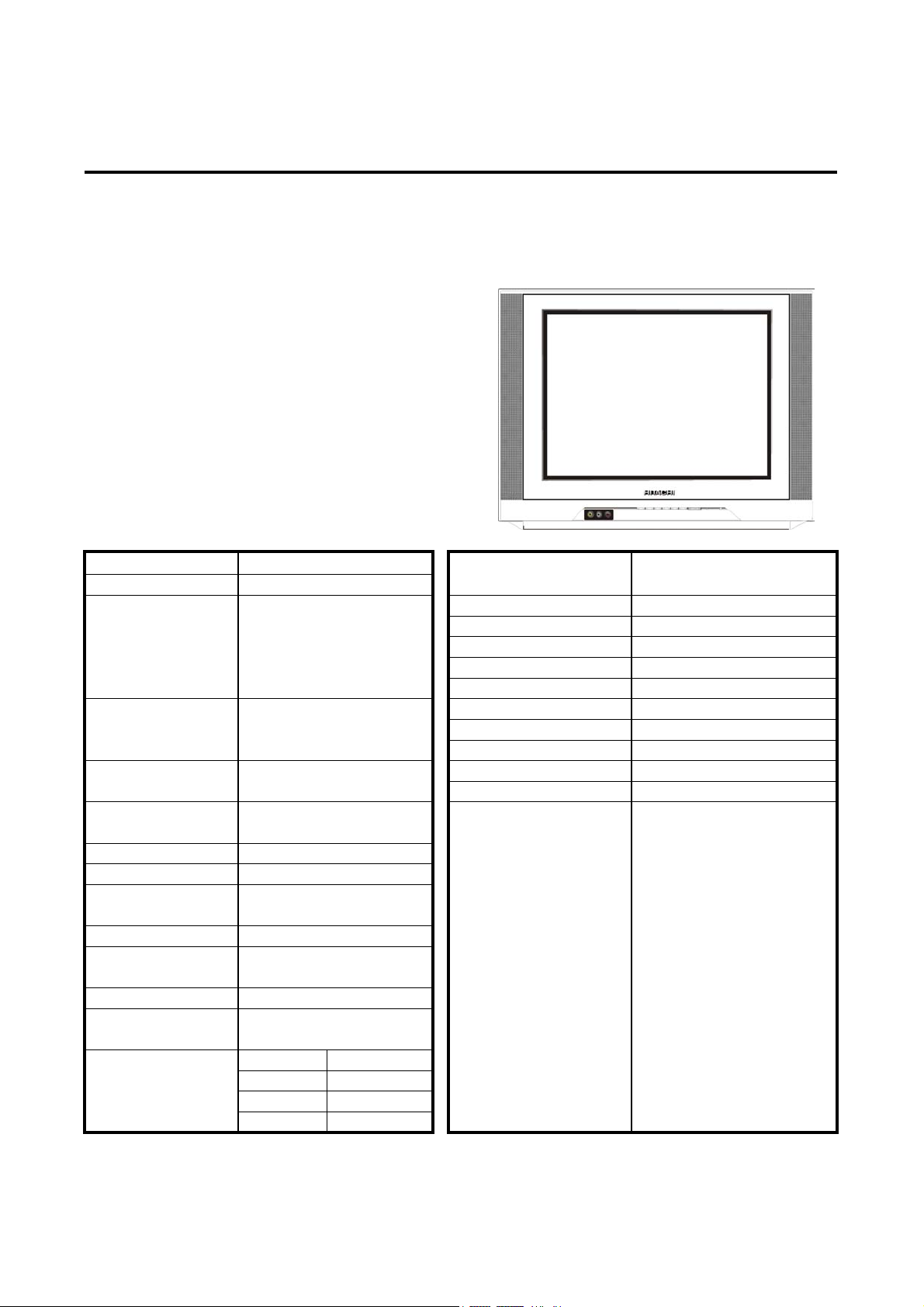
HITACHI
C21-FL21F HITACHI LTD. AV SYSTEMS
FEATURES
FULL FUNCTION REMOTE CONTROL
*
PRESET TUNING ( VOLTAGE SYNTHESIZER - AUTO PRESET, MANUAL , FINE )
*
HYPERBAND TUNER
*
AVL ( AUTO VOLUME LEVELLING)
*
CHANNEL SKIP
*
BLUE BACK
*
AUTO OFF
*
ON / OFF/ ALARM TIMER ( 0:00 - 24:00 )
*
MULTI LANGUAGE OSD
*
NR (NOISE REDUCTION)
*
AV STEREO
*
SPECIFICATIONS
SCREEN SIZE 21 INCH 90 DEG. DEF.
CHASSIS V2
RF: B/G/D/K/H/I-PAL,
RECEPTION SYSTEM
( FULL MULTI )
FREQUENCY COVERAGE
PRESETTING
PROGRAMME NO.
PROGRAMME UP / DOWN AND
SELECTION
AUDIO OUTPUT 5 W + 5 W ( MAX )
SPEAKER SIZE ( 5 x 9 cm ) X 2
POWER SUPPLY AC 100 ~ 264 V / 50Hz,60Hz
POWER PLUG CEE
POWER
CONSUMPTION
AERIAL INPUT 75 OHM COAXIAL
CONTROL - REMOTE BLUE BACK ON / OFF
OPERATION - MANUAL
TERMINALS
* TV OUT
B/G/D/K/K'/I-SECAM,M-NTSC
VIDEO: NTSC3.58 - 5.5/6.0/6.5,
NTSC4.43 - 5.5/6.0/6.5,
NTSC50,PAL60,SECAM60
44-863 MHz
100
RANDOM ACCESS
( USABLE RANGE )
89 W
VIDEO IN
* VIDEO OUT
AUDIO IN
* AUDIO OUT
2
1
2
1
OSD ENGLISH,CHINESE,MALAY,
RUSSIAN
CABINET STYLING TABLE
CABINET MATERIALS PLASTIC
HANDLE YES (SCOOP)
TV-SET DIMENSION (mm)
PACKAGE DIMENSION (mm)
N.WEIGHT ( kg ) 21.6
G.WEIGHT ( kg ) 24.6
20 FT CONTAINER
40 FT CONTAINER
45 FT CONTAINER
REMOTE CONTROL MENU
FUNCTION PRESET TUNING
605x489x448 (W x L x H)
660x545x533 (W x L x H)
136 SETS
304 SETS
340 SETS
PROGRAMME SELECTION
TV / VIDEO
PICTURE CONTROL
SOUND CONTROL
VOLUME CONTROL
MUTE
PICTURE AND SOUND MEMORY
NOISE REDUCTION
AUTO OFF ON / OFF
TIMER ( ON,OFF,ALARM )
STANDBY ON/OFF
RECALL
CHANNEL SKIP PRESET
SPECIFICATION ARE SUBJECT TO CHANGE WITHOUT NOTICE.
Page 3
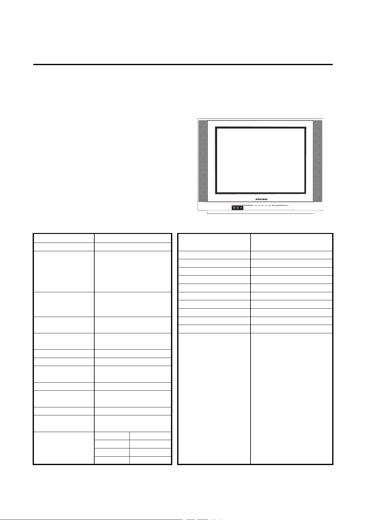
HITACHI
C21-FL21M HITACHI LTD. AV SYSTEMS
FEATURES
FULL FUNCTION REMOTE CONTROL
*
PRESET TUNING ( VOLTAGE SYNTHESIZER - AUTO PRESET, MANUAL , FINE )
*
HYPERBAND TUNER
*
AVL ( AUTO VOLUME LEVELLING)
*
CHANNEL SKIP
*
BLUE BACK
*
AUTO OFF
*
ON / OFF/ ALARM TIMER ( 0:00 - 24:00 )
*
MULTI LANGUAGE OSD
*
NR (NOISE REDUCTION)
*
AV STEREO
*
SPECIFICATIONS
SCREEN SIZE 21 INCH 90 DEG. DEF.
CHASSIS V2
RF: B/G/D/K/H/I-PAL,
RECEPTION SYSTEM
( MULTI )
FREQUENCY COVERAGE
PRESETTING
PROGRAMME NO.
PROGRAMME UP / DOWN AND
SELECTION
AUDIO OUTPUT 5 W + 5 W ( MAX )
SPEAKER SIZE ( 5 x 9 cm ) X 2
POWER SUPPLY AC 100 ~ 264 V / 50Hz,60Hz
POWER PLUG CEE
POWER
CONSUMPTION
AERIAL INPUT 75 OHM COAXIAL
CONTROL - REMOTE
OPERATION - MANUAL
TERMINALS
* TV OUT
B/G/D/K/K'/I-SECAM
VIDEO: NTSC3.58 - 5.5/6.0/6.5,
NTSC4.43 - 5.5/6.0/6.5,
NTSC50,PAL60,SECAM60
44-863 MHz
100
RANDOM ACCESS
( USABLE RANGE )
89 W
VIDEO IN
* VIDEO OUT
AUDIO IN
* AUDIO OUT
2
1
2
1
OSD ENGLISH,CHINESE,MALAY,
RUSSIAN
CABINET STYLING TABLE
CABINET MATERIALS PLASTIC
HANDLE YES (SCOOP)
TV-SET DIMENSION (mm)
PACKAGE DIMENSION (mm)
N.WEIGHT ( kg ) 21.6
G.WEIGHT ( kg ) 24.6
20 FT CONTAINER
40 FT CONTAINER
45 FT CONTAINER
REMOTE CONTROL MENU
FUNCTION PRESET TUNING
605x489x448 (W x L x H)
660x545x533 (W x L x H)
136 SETS
304 SETS
340 SETS
PROGRAMME SELECTION
TV / VIDEO
PICTURE CONTROL
SOUND CONTROL
VOLUME CONTROL
MUTE
PICTURE AND SOUND MEMORY
NOISE REDUCTION
BLUE BACK ON / OFF
AUTO OFF ON / OFF
TIMER ( ON,OFF,ALARM )
STANDBY ON/OFF
RECALL
CHANNEL SKIP PRESET
SPECIFICATION ARE SUBJECT TO CHANGE WITHOUT NOTICE.
Page 4
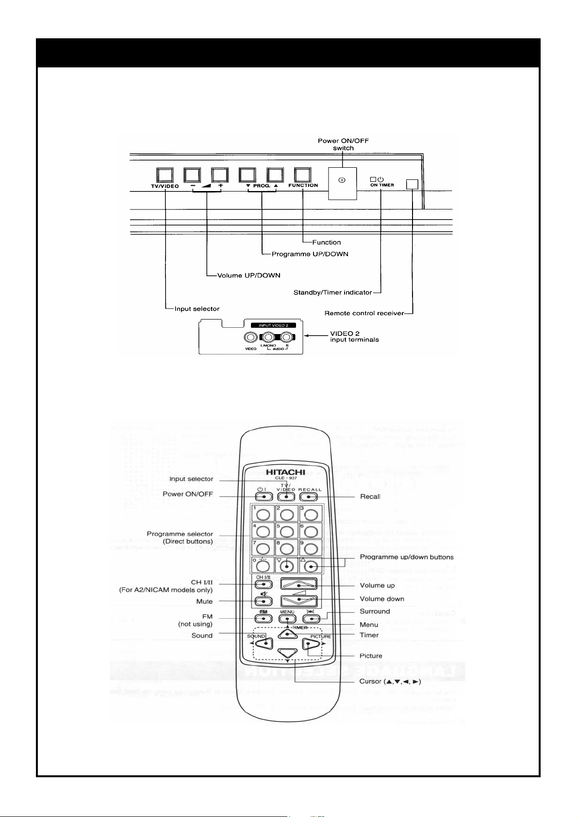
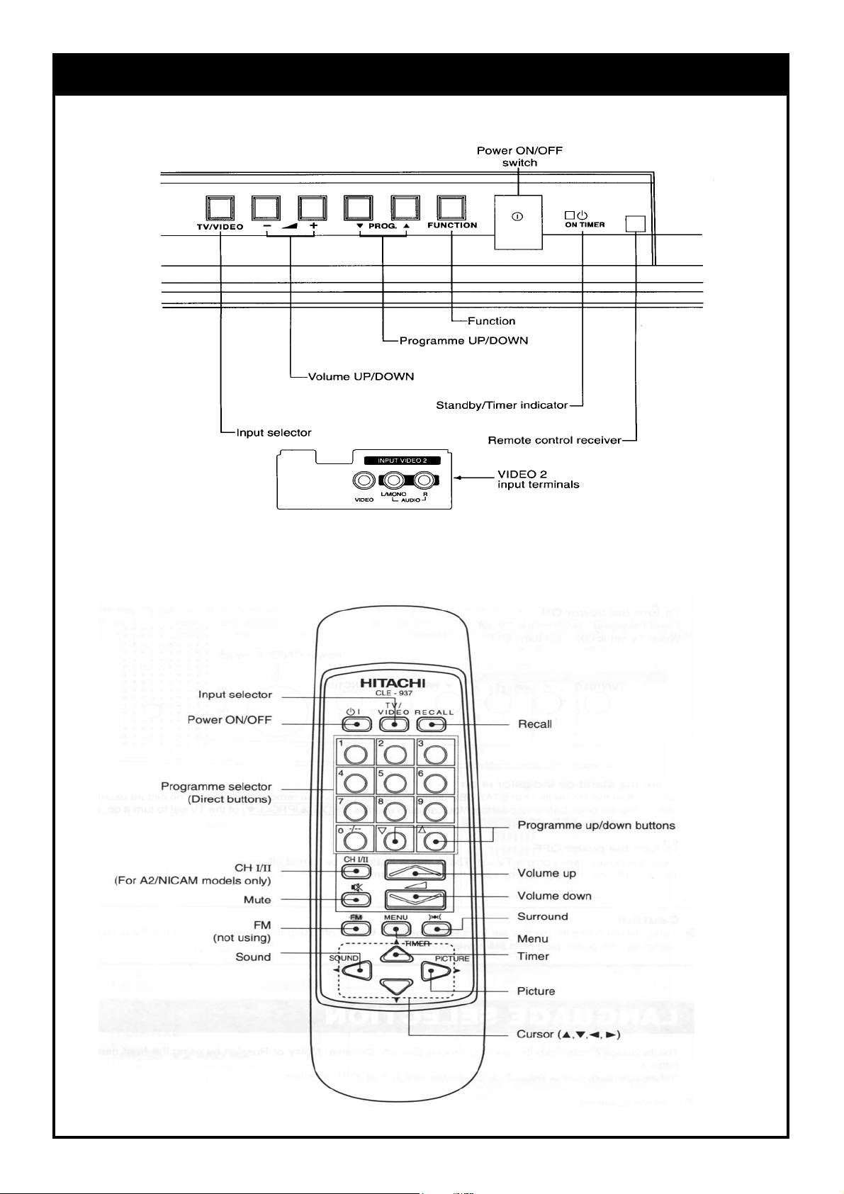
CONTROLS
L
FRONT PANE
REMOTE CONTROL UNIT
Page 5
CONTROLS
L
REMOTE CONTROL UNIT
FRONT PANE
Page 6

SAFETY PRECAUTIONS
WARNING: The following precautions should be
opserved.
1. Do not install , remove, or handle the picture tube in could produce X-radiation moderately in excess of de any manner unless shatter proof goggles are worn. sign levels. The high voltage must not, under any cir People not so equipped should be kept away while cumstances, exceed 34kV on the chassis.
picture tubes are handled. Keep picture tube away
from the body while handing.
2. When service is required, an isolation transformer receiver is the picture tube. The tube utilized for the
should be inserted between power line and the above mentioned function in this chassis is specially
receiver before any service is performed on the constructed to limit X - radiatuion.
chassis. For continued X-radiation protection, replace tube with
3. When replacing the chassis in the cabinet,ensure
all the protective devices are put back in place,such
as barriers, non - metallic knobs, adjustment or
compartment covers or shields, isolation resistors/ Many electrical and mechanical parts in HITACHI
capacitors, etc. television receiver have special safety related
4. When service is required, observe the original lead evident from visual inspection, nor can be protection
dressing. Extra precaution should be taken to afforded by them necessarily be obtained by using
assure correct lead dressing in the high voltage
circuitry area. Particularly note the R. G. B. lead wattage, etc. Replacement parts which have these
dressing. Ensure they are dressed well away from special safety characteristics are identified by marking
the horizontal scan and F.B.T. circuitry. with a on the schematics and replacement
5. Always use the manufacturer ' s replacement
component. Always replace original spacers and safety characteristics as the HITACHI recommended
maintain lead lengths. Especially critical components replacement one, shown in the parts list in this Service
are indicated thus on the parts list and Manual, may create electrical shock, fire, X - radiation,
should not be replaced by other makes.
Furthermore, where a short circuit has occurred,
replace those components that indicate evidence of Product Safety is continuously under review and new
overheating. instructions are issued from time to time. For the latest
6. Before returning a serviced receiver to the customer, Manual. A subscription to ,or additional copies of
the service technician must thoroughly test the unit HITACHI Service Manuals may be obtained at a nominal
to be certain that it is completely safe to operate charge from your HITACHI sales offices.
without danger of electrical shock, and be sure that
no protective device built into the instrucment by the
manufacturer has became defective, or inadvertenly The line output stage can develop voltages in excess
damaged during servicing. Therefore, the following of 25kV; if the E.H.T cap is required to be removed,
checks are recommended for the continued discharge the anode cap to chassis via a high value
protection of the customers and service techninians. resistor, prior to its removal from the tube.
HIGH VOLTAGE
High voltage should always be kept at the rated value
of the chassis and no higher. Operating at higher
voltages may cause a failure of the picture tube or high
voltage supply, and also, under certain circumstances
X-RADIATION
TUBES : The primary source of X - radiation in this
the same type as the original, HITACHI approved type.
PRODUCT SAFETY NOTICE
characteristics. These characteristics are often not
replacement components rated for higher voltage,
parts list in this Service Manual.The use of a substitute
replacement component which does not have the same
or other hazards.
information,always consult the current HITACHI Service
TUBE DISCHARGE
INSULATION
Insulation resistantce should not be less than 7 MΩ at
500 V DC between the mains poles and any accessible
metal parts. Also, no flashover or breakdown should
occur during the dielectric strength test, applying 3kV
AC or 4.25kV DC for two seconds between the main
poles and accessible metal parts.
- 2 -
Page 7
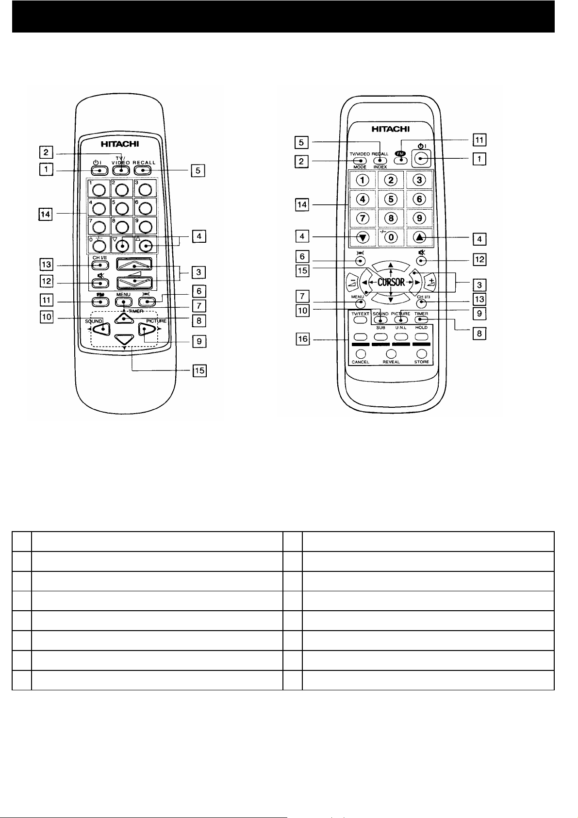
REMOTE CONTROL UNIT
FOR OTHER MODELS FOR T/TEXT MODELS ONLY
1. 9.
INPUT SELECTOR
2. 10.
VOLUME UP/DOWN
3. 11.
PROGRAMME UP/DOWN
4. 12.
RECALL
5. 13.
SURROUND SOUND
6. 14.
MENU
7. 15.
TIMER
8. 16.
PICTUREPOWER ON/OFF SWITCH
SOUND
FM (NOT USING)
MUTE
CHI/II (FOR NICAM/A2 MODELS)
PROGRAMME SELECTOR (DIRECT KEY)
CURSOR
T/TEXT FUNCTION KEY (T/TEXT MODELS ONLY)
- 3 -
Page 8
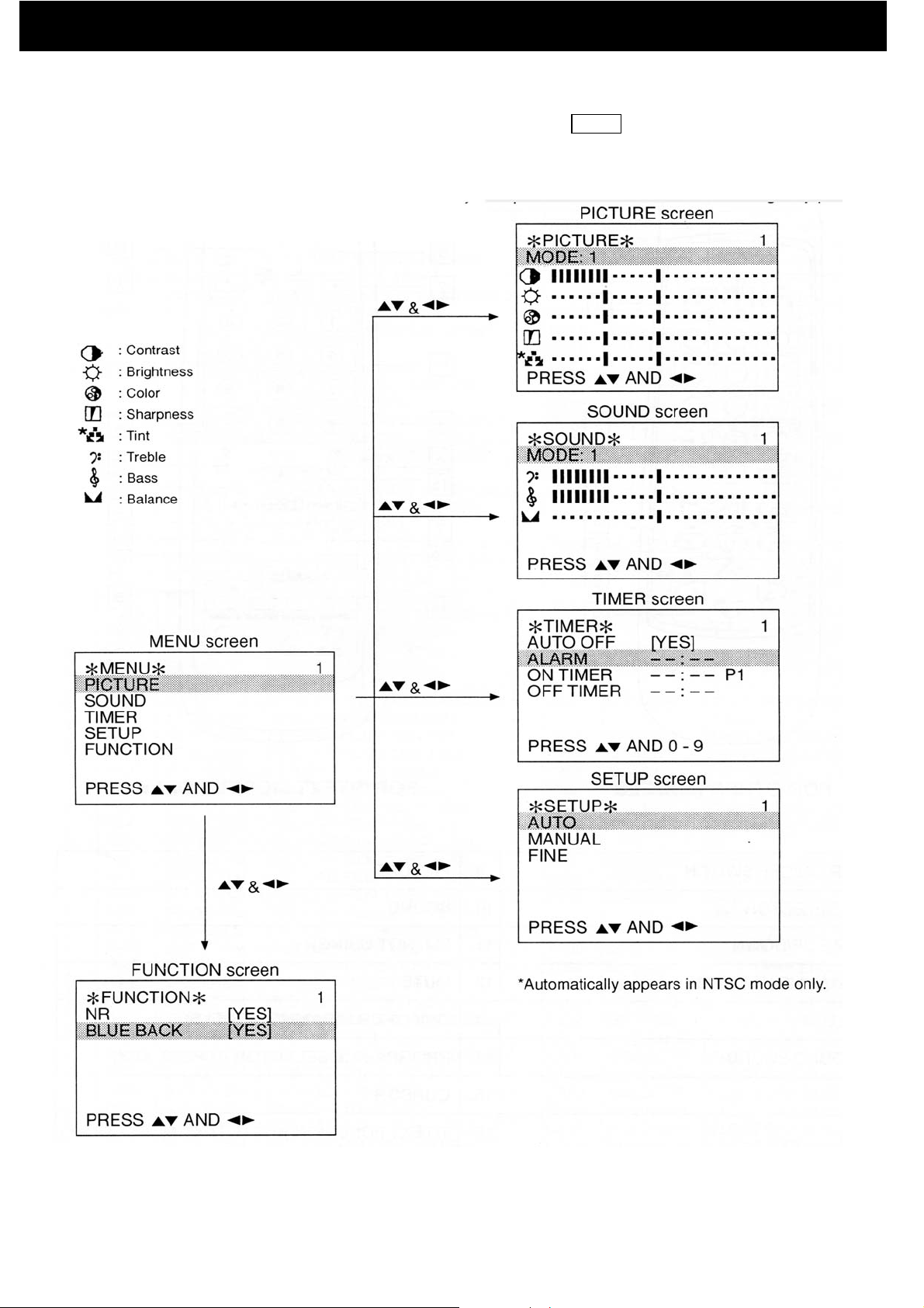
GENERAL OPERATIONS GUIDE
With this set, all adjustments/settings are performed by selecting from menu screens. Different menu screens and details
of adjustments/settings are shown below. To access the menu screen, press the MENU button, then select the item by
pressing the left/right cursor buttons.
- 4 -
Page 9
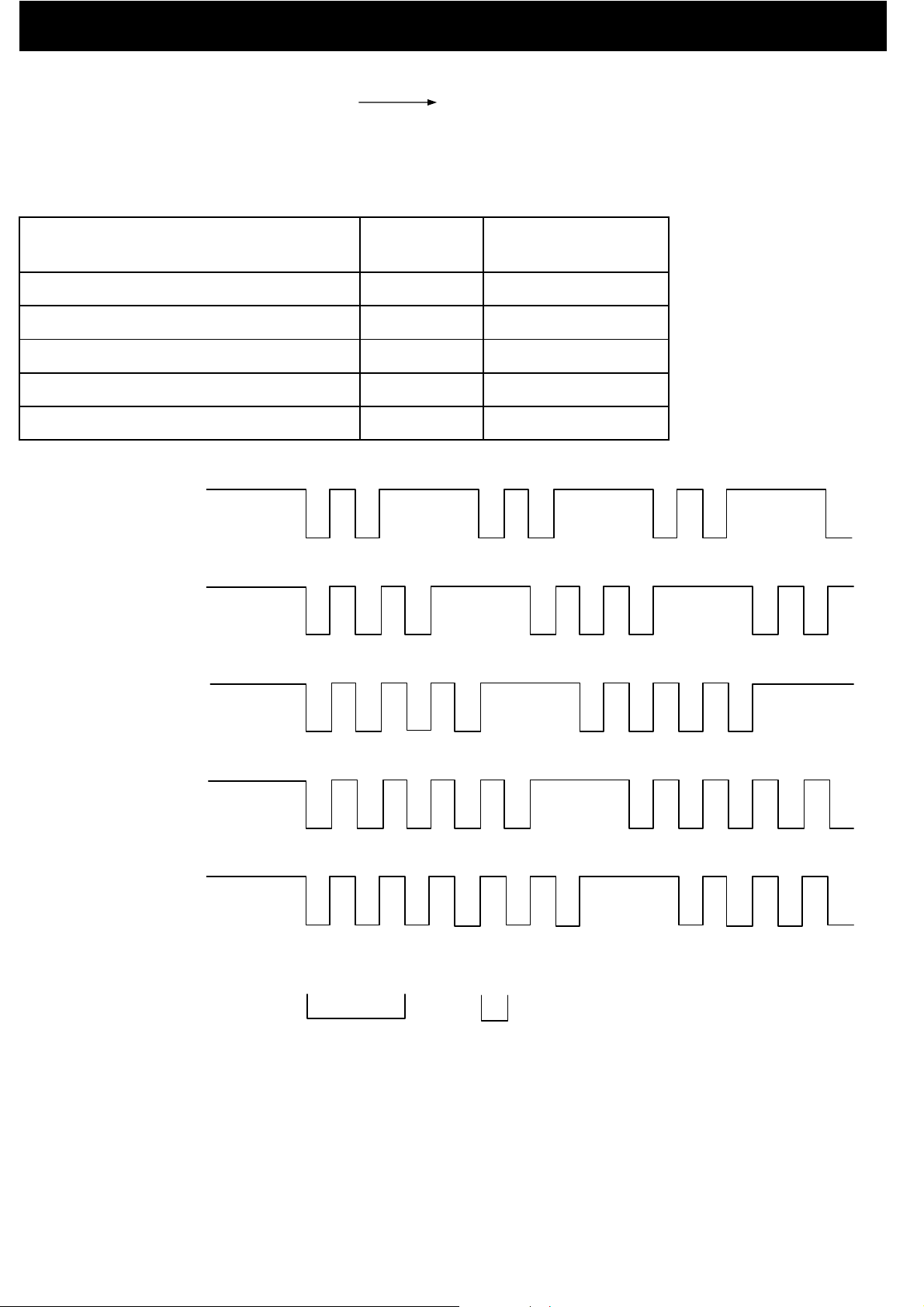
FAILURE DETECTING FUNCTION OF MAIN DEVICES
r
2
9
x
In V3AR ,failure of Main devices can detect by the blinking indication of LED at front panel.
( Example : LED blinking time is 2 in cycle I002 is out of order. )
If an IIC error occurred, the LED, D001 blinks at 1Hz, 50% duty cycle.
The blinking times are as below.
Failure Device
EEPROM, AT24C04
UOC, TDA935x/6x/8
Audio Processor, TDA985
PLL Tuner, TUHAF4EG - 775F
Table 3. Error LED blinking times
EEPROM
CCT.No.I002
[AT24C04]
V/C/J TV Processo
CCT.No.I001
[TDA9381/86/65]
ON
OFF
ON
OFF
CCT.No.
IA01
U001
IN01
Bus Error LED
Blinking Time
2I002
3I001
4
5
6NICAM, MSP3415D / MSP3417D
HiFI Audio Processor
CCT.No. IA01
[TDA9859]
PLL Tuner
CCT.No. U001
[TUHAF4EG - 775F2]
SOUND DECODER /
DEMODULATOR
CCT. No. IN01
[MSP3415 / MSP3417]
Figure 1. Error LED blinking times
ON
OFF
ON
OFF
ON
OFF
2S 0.5S
- 5 -
Page 10

CIRCUIT DESCRIPTION
V
V
V
V
V
V
V
V
V
V
V
t
t
r
r
r
t
t
y
)
A
d
r
)
d
r
t
t
t
t
t
t
t
t
t
t
t
t
V
t
V
A
r
w
A
r
A
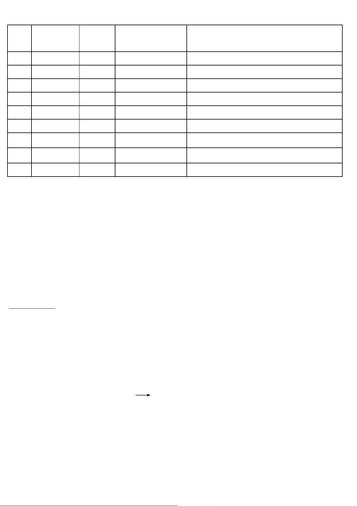
Selection and CPU circuitry
IC type, TDA9381/86/65 performs functions like IIC controls, channel selection, on-screen display ,search
tuning, systems selection amongst others. The pin's functions of TDA9381/86/65 are presented in the table shown
below.
Pin
numbe
1
2
Signal
name mode
Powe
SCL
3SD
4
5
6
Alarm
SAW S
AV S-DET
SW FE/A
7
8
9
10
11
Key - In
V2/V1
VSSC/P
Led
ON/OFF Mute
I/O
Outpu
I/O
I/O
Outpu
Outpu
Inpu
Outpu
Inpu
Outpu
-
Outpu
Outpu
Configuration
P.P. 3.3
O.D. 5
O.D. 5
O.D. 5
O.D. 3.3
H.I. 5
O.D. 5
H.I. 3.3
O.D. 3.3
-
O.D. 3.3
O.D. 3.3
Function
0 = Stand-by, 1 = On
Clock of main I
Data of main I
2
C - bus
2
C - bus
PWM output for Beep sound
1 = M, 0 = Others
Detect for S-VHS (not mono chassis
FE/AV switch (mono chassis)
Local analogue keyboar
1 = Video:2, 0 = Video:1
Digital ground for µ-controller core and peripher
LED Drive
1 = Mute on, 0 = Mute off (Under Standby
12
13
14
15
16
17
18
19
20
21
VSS
SECPLL
VP2
DECDIG
PH2LF
PH1LF
T
DECBG
AVL/EWD
VDRB
22 VDR
23 IFIN1
24 IFIN2
-
-
-
-
-
-
-
-
Outpu
Outpu
Outpu
Inpu
-
nalog ground of Teletext decoder and digital groun
of TV-processo
-
-
-
-
-
-
-
-
-
-
-Inpu
SECAM PLL decoupling
nd
2
supply voltage TV-processor (+8V)
Decoupling digital supply of TV-processo
Phase-2 filte
Phase-1 filte
Ground 3 for TV-processo
Bandgap decoupling
East-West drive outpu
Vertical drive B outpu
Vertical drive A outpu
IF input 1
- IF input 2
- 6 -
Page 11

t
r
Pin Signal
t
t
r
t
t
t
A
r
r
r
t
t
t
t
t
t
t
t
t
t
t
t
r
t
t
t
t
t
t
t
t
t
t
t
t
A
y
e
t
t
r
t
A
t
t
numbe
Configuration
I/O
name mode
Function
25 IREF Inpu
26 VSC - Vertical sawtooth capacito
27 AGCOUT Outpu
-
-
28 AUDEEM Outpu
29 DECSDEM - Decoupling sound demodulato
30 GND2 - Ground 2 for TV processo
31 SNDPLL - Narrow band PLL filte
32 REFO Outpu
33 HOUT Outpu
34 FBISO Inpu
35 AUDEXT Inpu
36 EHTO Inpu
-
-
-
-
-
-
-
37 PLLIF - 38 IFOu
Outpu
39 +8v - -
Reference current inpu
Tuner AGC outpu
udio deemphasis-
Subcarrier reference outpu
Horizontal outpu
Flyback inpu
External audio inpu
EHT/overvoltage protection inpu
IF-PLL loop filte
IF video output / selected CVBS outpu
Main supply voltage TV-processor (+8V)
40 CVBSINT Inpu
41 GND1 _ 42 CVBS/Yin Inpu
43 Cin Inpu
44 AUDOUT Outpu
45 INSSW2 - 46 R2/VIN - 47 G2/YIN - 48 B2/UIN - 49
BCLIN Inpu
50 BLKIN Inpu
51
52
53
54
RO Outpu
GO Outpu
BO Outpu
VDD
--Analog supply of Teletext decoder and digital suppl
- Internal CVBS inpu
Ground 1 for TV-processo
-
-
-
External CVBS/Y inpu
Chrominance input (SVHS)
udio outpu
No connection
No connection
No connection
No connection
-
Beam current limiter input/V-guard inpu
- Black curren
-
-
-
Red OSD outpu
Green OSD outpu
Blue OSD outpu
of TV-processor (3.3 V)
55
VPE - - OTP Programming Voltag
- 7 -
Page 12
r
Pin Signal
)
y
t
t
t
t
g
V
t
)
t
t
numbe
Configuration
I/O
name mode
Function
56 VDDC - -
Digital supply to core (3.3V
57 OSDGND - - Oscillator ground suppl
58 XTA/IN Inpu
59 XTA/OUT Outpu
60 RESET Inpu
61 VDDP - -
62 SCL(EEP) I/O
63 SDA(EEP)
I/O
64 RC-In Inpu
Note 1 : Abbreviation of pin configulation mode : O.D. Open Drain
O.D. 3.3V
O.D.
H.I.
-
-
-
Crystal Oscillator inpu
Crystal Oscillator outpu
Rese
Digital supply to periphery (+3.3 V
2
C-bus for EEPROM
2
C-bus for EEPROM
3.3V
3.3
Clock of secondary I
Data of secondary I
Input for Remote control decodin
Q.B. Quasi-Bidirectional
H.I. High-Impedance
P.P. Push-Pull
Note 2 : During reset all pins are Quasi-Bidirectional mode.
Tuner and IF
The Tuner (U001)used on V3AR chassis is powered up by the 5V supply. It is IIC bus controlled and covers VHF, UHF,
CATV Band (Mid, super, and hyper).
The IF output from Tuner ( pin 11 of U001) is applied to the amplifier Q201.
For multi-system model with M-NTSC, switchable saw filter is used. Q001 at pin 2 of X003 servers to select the IF
signal between M/N mode to other modes ( e.g. B/G, D/K ) before demodulation is carried out at I001.
i.e. at M mode: Base of Q001 High
I001 (TDA9381/9386/9365) besides begin the microcontroller, incorperates video / chroma / deflections /
teletext features and video/audio switching. It performs auto color identification of PAL/SECAM/NTSC, sync
separation , AFC, HV oscillator and output RGB signals.
- 8 -
Page 13

IF signal is sent to I001 pin 23 and 24 for demodulation. For MONAURAL and AV STEREO mode, the demodulated
:
V
d
e
e
n
.
n
.
A
a
n
a
n
d
A
e
K
f
fLow
signals are sent for video and audio selection. For NICAM/A2 mode, the demodulated signals are sent for video
processing only.
The composite video signals after demodulation are sent to a series of bandpass filters (X004 - X006) through
pin 38 of I001. The system selection is as follows
Signal output to pin 40 of I001
Buffers
Q003
High B/G, I, D/
The selected RF video signal is sent to pin 40 of I001 and output AV terminal. The external video signal from input A
1 and 2 terminal also goes through pin 38 to output AV terminal. This is done by use of internal switch control
Q004
Of
Q005
M
Of
Video / Chroma
I401 select Video 1 or Video 2 signals and sent to pin 42 of I001. The video input signals (RF at pin 40, Video 1 an
Video 2 at pin 42) are selected using internal AV switch in I001 controlled by IIC bus. The selected video signals ar
processed with teletext. After color indentification and decoding, the color difference signals are matrixed with th
luminance signal to obtain the RGB signals. The RGB can be controlled by contrast and brightness and output at pi
51 - 53 to CRT PWB, in sequence with the OSD RGB
Internal sync separator and H/V oscillator of I001 produce H and V drive signals which are applied to deflectio
circuits for horizontal and vertical scanning
udio mode switching
For MONAURAL (without NICAM/A2) sound models, two audio switching is carried out. The RF audio signal afte
demodulation in I001 is output at pin 28 of I001 to pin 10 of I401. I401 perform audio selection using control sign
between the RF audio signal and external audio signal input (pin 8) of I401. The audio output at pin 6 of I401 is se
to output AV terminal.
The external audio input is also sent to pin 35 of I001 to perform the second audio switching with the RF audio sign
in I001. The selected audio signal goes through volume control before output at pin 44 of I001 to L(pin2) and R(pi
5) of I402. Amplification took place and output at L (pin12) and R (pin7) of I402 to the speakers
For NICAM/A2 sound models, the IF signal is input at pin 1 of X002 (saw filter) and output at pin 4 and 5 to pin 28 an
pin 29 of I001. After demodulation, the audio signal output at pin 35 to NICAM PWB (pin 2 of EN01) for NICAM proces
sing. The NICAM audio output at pin L (pin 10) and R (pin 11) of EN01 goes to SOUND PWB at pin 9 and 10 of EA01
V STEREO sound models, the audio signal is output at pin 44 of I001 and goes to SOUND PWB at pin 9 and 10
For
of EA01.
Audio input (L and R) from AV 1 And 2 terminal are input to pin 1 - 4 of EA01. Audio switching, volume comtrol, trebl
and bass are processed at IA01 (TDA9856). The L (pin 7) and R (pin6) output at EA01 goes to output AV terminal
The L (pin 12) and R (pin 11) at EA01 goes to I402 for amplification before sending to the speakers
- 9 -
Page 14

POWER SUPPLY CIRCUIT
d
e
y
Commutating voltage from AC output rectified by D901A and produces approximately 300V to pin 3 of I901.
Current flowing through R904, R917, causes I901 pin 4 to initially turn on.
Secondary voltage are then induced winding V1 - V2 in T901, I901 supply voltage is obtained via R906, D906, C909
and applied to pin 4 of I901, thereby maintaining I902 switching operation. Secondary voltage in S1, S3 winding is
rectified by D951 to produce +B = 95V which is smoothed by C953. S2, S4 winding produces 16V from D952, and
this is smoothed by C956.
Error amplifier Q951 is set to a pre-determined level by resistor network R952 - R956, and reference voltage D957
Should the +B voltage rise, base voltage of transistor Q951 will become more positive, and this difference is ampli
fied by the error amplifier Q951. An output is applied to I901 feedback pin 1 through optocoupler (CTR) I902 an
controls ON time of I901 internal circuit . In this way, +B voltage is regulated and maintained at a constant level.
D973 offers protection that it should the voltage level rise excessively
When the standby mode is selected, pin 1 of I001 will go " low " . As a result Q954 and Q955 are turned off, and th
supply voltage for the horizontal start of pin 33 of I001 though R980/D980/R071 disappears. Therefore shutting
down the deflection drive stages of I001, deflection output stage will then cease for as long as the standb
condition exist.
- 10 -
Page 15

n
ADJUSTMENT INSTRUCTIONS
A. IIC ADJUSTMENTS
Most of the adjustment items in the V3AR chassis are controlled by IIC. Adjustment items include video chroma IC
(I001, UOC) control, sound multiplex ICs, horizontal & vertical deflection and others.
To start the IIC adjustment, first turn off AC power switch. Press and hold down the TV/Video local key and the
press the power switch. Release both buttons after the following display appears on screen.
NO DATA
001 : 28
002 : 28
003 : 28
004 : 80
005 : 80
006 : 06
007 : 75
: ADJUST
RECALL : SAVE
Select the Adjust items by or cursor
Select the Adjust items by or cursor
To select the adjustment items (e.g. RGB level, sub-brightness level etc…), press the or cursor button on
Remote control handset. To adjust the data of selected item, press or cursor button on Remote control
handset .
After completing the adjustments, press the RECALL buttom on Remote control handset to memorize the data.
Press MENU button or turn off the TV set to end the IIC adjustment.
- 11 -
Page 16

The following are the IIC Bus control and adjustment data for reference.
R
R
T
Y
R
Table 1: IIC-Bus Control and Adjustment
ADJ
No. NAME OF ADJUSTMENT
1 WHITE POINT
2 WHITE POINT G 00-3F 00
WHITE POINT B
3
HORIZONTAL POSITION
6
SUB-COLO
7
SUB-TINT
8
SUB-BRIGHT
9
SUB-CONTRAST
10
SUB-SHARPNESS
11
PHASE 1 TIME CONSTAN
13
VIDEO IDENT MODE
14
DATA INITIAL
RANGE
00-3F 00
00-3F
00-3F
00-3F
00-3F
00-3F
00-3F
00-3F
00-03
00-01
DATA
(hex)
00
16
1E
1E
1E
08
1E
00
01
ITEMS AFFECTED DURING CHANGE
MEMORY
I002
OO
O
O
O
O
O
O
O
O
O
O
CPT
O
O
O
X
X
X
X
X
X
X
TDA9381/86/65
I001
O
O
O
O
O
O
O
O
O
O
O
FIELD FREQ.
15
INTERLACE
16
ENABLE FAST BLANKING
17
SYNCHRONIZATION
18
19
COLOR DECODER MODE
20
RGB BLANKING
21
BLACK CURRENT STABILISATION
22
BLACK LEVEL OFF SET
23
BLACK LEVEL OFF SET G
24
VERTICAL DIVIDER MODE
25
SEARCH TUNING MODE
26
VIDEO IDENT MODE
27
FORCED SLICING LEVEL FOR V.S
00-03
00-01
00-01
00-01
00-0F
00-01
00-01
00-0F
00-0F
00-01
00-01
00-01
00-01
02
01
00
00
08
00
01
00
00
00
00
01
01
O
O
O
O
O
O
O
O
O
O
O
O
O
X
X
X
X
X
X
X
X
X
X
X
X
X
O
O
O
O
O
O
O
O
O
O
O
O
O
ENABLE VERTICAL GUARD
29
00-01
- 12 -
00
O
OX
Page 17

R
L
W
R
Y
W
T
R
ADJ
DATA INITIAL
ITEMS AFFECTED DURING CHANGE
No.
30 SERVICE BLANKING 00-01 00
31 MATRIX NTSC 00-01 01
32 PAL,SECAM/NTSC 00-01 01
33 BYPASS OF CHROMA BASE BAND DL 00-01 00
34 AVL/SUBCARRIE
35 SYNCHRONIZATION OF OSD/TEX
36 AFC WINDO
37 IF SENSITIVIT
39 VIDEO MUTE 00-01 00
40 AGC TAKE OVE
47 PLL DEMODULATOR FREQ. 00-05 02
48 VERTICAL ZOOM 00-3F 19
NAME OF ADJUSTMENT
RANGE
00-03 00
00-01 01
00-01 01
00-01 00
00-3F 20
DATA MEMORY CPT TDA9381/86/65
(hex) I002
I001
XX O
OX O
OX O
OX O
OX O
OX O
OX O
OX O
OX O
OX O
OX O
OX O
50 SW-OFF V-OVERSCAN 00-01 00
51 CHROMA BANDPASS C-FREQ. 00-01 00
54 VERTICAL SHIFT(V POSITION) 00-3F 28
55 VERTICAL AMPLITUDE(V SIZE) 00-3F 1B
57 S-CORRECTION 00-3F 20
58 BLACK STRETCH 00-01 01
59 VERTICAL SLOPE 00-3F 1B
60 HOLIZONTAL PARALLELOGRAM 00-3F 1B
61 HOLIZONTAL BO
63 AUTO COLOR LIMITTING 00-01 01
64 IF AGC SPEED 00-03 01
66 CATHODE DRIVE LEVEL 00-0F 0F
69 FAST FILTER IF-PL
71
FORCED COLOR-ON
00-3F 1B
00-01 00
00-01
00
OX O
OX O
OO O
OO
OO O
OX O
OO O
OO O
OO O
OX O
OX O
OX O
OX O
O
X
O
72
GAIN FM DEMODURATO
73
SOUND MUTE
00-01
00-03
- 13 -
00
03
O
O
X
X
O
O
Page 18

DATA INITIAL
ITEMS AFFECTED DURING CHANGEADJ
No.
74 WINDOW SELECTION SOUND PLL 00-01 00
75 QSS OUT OR AM OUT 00-01 00
76 EHT TRACKING MODE 00-01 00
77 RGB/YUB SWITCH 00-01 00
78 RGB BLANKING MODE 00-01 00
80 V-SCAN DISABLED 00-01 00
106 EW WIDTH 00-3F 1F
107 EW PARABOLA/WIDTH 00-3F 1F
108 EW UPPER CORNER PARABOLA 00-3F 1F
109 EW LOWER CORNER PARABOLA 00-3F 1F
NAME OF ADJUSTMENT
RANGE
DATA MEMORY CPT TDA9381/86/65
(hex) I002
I001
OX O
OX O
OX O
OX O
OX O
XX O
OO O
OO O
OO O
OO O
110 EW TAPEZIUM 00-3F 1F
111 Y DELAY 00-0F 06
112 Y DELAY 00-0F 0A
113 DISABLE FLASH PROTECTION 00-01 00
114 X-RAY PROTECTION 00-01 00
139 A2 STEREO JUDGE>X 00-7F 0F
140 A2 BILINGUAL JUDGE>X 80-FF
141 FM-AM SWITCHING 000-3FF 380
142 OUTPUT LEVEL OF NICAM 00-7F 7A
143
OUTPUT LEVEL OF A2
144 75
OUTPUT LEVEL OF FM
00-7F
00-7F
F2
74
OO O
OX O
OX O
OX O
OX O
OX X
OX X
OX X
OX X
OX X
OX X
- 14 -
Page 19

SHIPPING DATA OF IIC SERVICE MODE
(apply only when the memory IC, I002, change.)
1. Select the adjustment item, 323(Initialization of memory IC, I002) by pressing the or cursor button on
Remote control handset.
2. Set data of adjustment item, 323 to "01" by pressing the or cursor button on Remote control handset.
3. Press the RECALL button on Remote control handset to memorize the data.
The data of adjustment item, 323 is changed to "00" after all memory IC's data are initialised.
4. Press AC power switch to turn off the TV set.
5. Press AC power switch to turn on the TV set.
Result : The memory IC, I002 is initiallized.
6. After initialization, set the shipping data as show in Table 2.
7. Go to previous page and adjust the IIC data in Table 1
- 15 -
Page 20

Table 2 : Shipping Data
- 16 -
Page 21

+B ADJUSTMENT
A
e
A
x
r
T
PREPARATION PROCEDURES
1.
AC input voltage 230 + 5V(50Hz)
2.
Turns on the set and set the brightness
and contrast to Max.
(Signal : Philips Pattern)
3.
After 30 sec heat-run, check & adjust the
+B voltage +B voltage : C935 + side
VERTICAL CENTER ADJUSTMENT
PREPARATION PROCEDURES
1.
Turns on the TV set & heat run about 5 min. Select the IIC control address No. 54.
2.
Receive the circular pattern signal Set the horizontal center line to vertical center maker
3.
AC 230 +
5V
1.
1.
2.
djust R954 to obtain +B voltage as below
95 +
Measuring Points
GND : C935 - sid
of CRT by adjustment of IIC.
i.e.
0.5V
VERTICAL SIZE ADJUSTMENT
PREPARATION PROCEDURES
Turns on the TV set & heat run about 5 min. Select the IIC control address No. 55.
1.
Receive the circular pattern signal
2.
Set all picture settings as below. i.e.
3.
i.e.
Contrast : Ma
Brightness : Cente
AC 230 + 1V
4.
Vertical center
marker of CR
1.
2.
3.
4.
djust IIC data to obtain the following condition.
PAL
Picture Top : Inner circle reach the edge of TV raster.
Picture Bottom : Inner circle reach the edge of TV
Receive the NTSC circular signal, and check the
picture size after the above V-size adjustment.
If a> 0mm, go back to IIC control No. 54(V-center
adjustment) and increase the IIC data by 1 position.
…………………………………..
……………………….
a
NTSC
- 17 -
Page 22

VERTICAL SLOPE ADJUSTMENT(Must be done before V. Center and V. Size Adjustments
)
PREPARATION PROCEDURES
1.
Turns on the TV set & heat run about 5 min. Select the IIC control address No. 30.
2.
Receive the circular pattern signal (PLL) Press or key on remote con. handset so
3.
Set all picture settings as below. that the button half of the picture is blanked.
i.e. i.e.
Contrast : Max
Brightness : Center Botton half of
4.
AC 230 +
1V picture blanked
1.
2.
3.
Select the IIC Control address No. 59.
4.
Adjust the vertical slope until the horizontal center
line is just at the position where the blanking starts.
5.
Select the IIC Control address No. 30.
6.
Press or key on remote con. handset so
that picture appears again.
HORIZONTAL PHASE ADJUSTMENT
PREPARATION
1.
Receive the circular pattern signal. Select the IIC control address No. 06.
PROCEDURES
1.
2.
Adjust the picture center to meet the CRT geometrical
center.
- 18 -
Page 23

WHITE BALANCE ADJUSTMENT
A
A
A
n
n
r
1.
Switch on the TV set for at least 20 mins. Set black stretch (IIC service no. 58) to "0".
2.
Adjust this adjustment after the Purity adjustment. Set to lateral line mode (IIC service no. 80) from
3.
Ensure the vertical incident illumination on CRT surface "0" to "1".
to be 20 lux or less. Turns the Screen VR of FBT clockwise and set it to
4.
Receive the white balance raster. the position where the bright color line starts to appear.
5.
Turns the low bright adjustment VRs R830, R831 & Takes the first appeared color as the reference,
R832 fully counterclockwise. adjust R830(Green), R831(Blue) & R832(Red) till all
6.
Select the IIC control address No. 01 (White point red), appear to the same level as the reference color.
No. 02 (White point green), No. 03 (White point bule) Note : Don't turn the VR of the reference color.
and set all data to 1FH
7.
Turns the screen VR of FBT fully counterclockwise. line is just slightly seen.
8.
Select the IIC control address No. 10 (Sub-contrast) Release the lateral line mode by changing IIC service
and set the data to 1FH. no. 80 from "1" to "0".
9.
Select the IIC control address No. 09 (Sub-brightness) Set black stretch (IIC service no. 58) to "1".
and set the data to 26H. Set the White Balance meter probe at the center of
PROCEDURESPREPARATION
1.
2.
3.
4.
5.
6.
7.
8.
9.
djusts the Screen VR of FBT until the white raster
the screen.
djusts the following keys of IIC and R830/R831/R832
to the desired W/B color temperature.
IIC Address No
R Drive 01
B Drive 03
Notes :
a. Fix the G Drive at 1FH(IIC Address No. 02),
do not adjust.
b. To obtain the low brightness and high
brightness conditions, adjust the brightness
control of remote control handset.
SUB-TINT ADJUSTMENT
PREPARATION PROCEDURES
1.
Receive the color bar signal (NTSC). Select the IIC control address No. 08.
2.
Set the user control to Contrast: Max, Other: Center. Set IIC address No. 08 to 1E.
SUB-BRIGHTNESS ADJUSTMENT
PREPARATION PROCEDURES
1.
Switch on the TV set for at least 20 min. Select the IIc control address No. 09
2.
Ensure the vertical incident illumination on CRT surface
to be 20 lux or less. portion becomes lighter black.
3.
Receive the color bar pattern.
4.
Set the following setting by remote control handset.
Contrast : mi
Color : mi
Brightness : Cente
1.
2.
1.
2.
djust the data until A2 portion becomes black and A3
A7 A6 A5A4 A3 A2 A1
complete black
lighter black
- 19 -
Page 24

Y
V
Z
T
V
V
Z
V
V
T
T
V
V
V
V
R
V
V
K
V
K
V
R
R
R
R
R
R
R
R
R
R
R
R
R
R
R
R
R
R
R
R
R
R
R
R
R
R
R
R
R
R
R
K
T
K
W
P
R
P
R
R
W
R
T
V
V
T
Z
T
V
T
V
T
T
K
R
V
R
V
V
R
R
R
)
V
A
R
5
0
X
C
R
R
X
5
K
R
9
V
V
V
R
V
V
R
R
REPLACEMENT PARTS LIST
PRODUCT SAFETY NOTE : Components marked with a have special characteristics important to safety. Before
replacing any of these components, read carefully the PRODUCT SAFETY NOTICE of this Service Manual. Don't degrade
the safety of the receiver through improper servicing
SYMBOL
No.
#0102 C009
#0103
#0105
#0112
#0113
#0155
#0301
#0662
#0902
#0903
#0904
#0905
#0906 4520881
#0907 3720501
#0908 8821234
B001
C002
C003
C004
C005 CER CAP SL 820UF 50
*C005
C006 MYLAR-CAP 0.022UF K 50V AMZ
C007 0800316
C008 0800299
PART No.
MJ01401
8813123
8821113
424344
MA01232
4519501
4519507
3701202
3746073
NA40151
3446473
4520881
4520883
MA01313
4340683
452088
A02 JT21881
JK08131
JK08132
0800325
0800291
0880039
0890086
0890282
0800316
DESCRIPTION
STL MS BH2.5X20 Y2
STL SW M2.6 YZP
STL HEX NUT TZM2.6 YZ
INSULATING WASHE
HEAT SINK S2 TC30 1MM
HEAT SIN
3X10B TNE SCRE
3X6 STL B7 BH YZP SCRE
G7 PCB HOLDE
V2 PROTECT METAL
(FOR FRONT AV STEREO MODELS ONLY)
POW HEATSINK H30 A6063S-T
M3X8 SCREW WITH WASHE
M3X12 SCREW WITH WASHE
HEAT SIN
HEAT SIN
M3X10 SCREW W/WASHER CMT299
M3X8 SCREW WITH WASHE
LEAD CLAMP CPT 143X/213
BS NUT M3(2)NIC
NICAM PCB ASSY (SKD)
V3AR MAIN PWB (TOOLING)
(FOR 21" ROUND CPT MODELS ONLY)
V3AR MAIN PWB (TOOLING)
(FOR 14,20" ROUND CPT MODELS ONLY
ELECT CAP SMG 100UF 10
ELEC CAP SMG 10UF 16
(NOT FOR NICAM/A2 MODELS)
CAP POLY FILM 0.0047UF K 50
(NOT FOR NICAM/A2 MODELS)
(NOT FOR NICAM/A2 MODELS)
ELEC CAP SMG 2.2UF 50
ELECT CAP SMG 47UF 10
(FULL MULTI SYS MODELS ONLY)
ELECT CAP SMG 47UF 10
ELECT CAP SME 22UF 16
SYMBOL
No.
C012#0104
C013
C0163442421
C017
C018#0114
C019#0115
C021#0153
C022IEC CORD HANGER CPT 213
C023
C024
C025#0661
C026
C027
C028
C029
C030
C031 0800288
C032
C035
C037
C038
C039B001
C040
C041
C042
C044
C046
C047
C048
C049
C050
C051
C052
C053
PART No.
0800288
0890115
0890115
0800324
0890087
0800325
0890087
0880048
0880044
0880035
0880039
0880037
0800279
0880198
0880198
0880048
0800282
0880016
0880044
0880016
0880014
0800324
0880012
0890087
0880016
0880012
0880012
0800324
0890087
0800324
0880012
0800326
0800326
0800315
DESCRIPTION
ELECT CAP SMG 4.7UF 50
(NOT FOR BILINGUAL & NICAM/A2 MODELS)
CER CAP SL 12PF 50V J
CER CAP SL 12PF 50V J
ELECT CAP SMG 100UF 6.3
CER CAP B 1000PF 50V
ELECT CAP SMG 100UF 10
CER CAP B 1000PF 50V
CAP POLY FILM 0.022UF K 50
CAP POLY FILM 0.01UF K 50
CAP POLY FILM 0.0022UF K 50
CAP POLY FILM 0.0047UF K 50
CAP POLY FILM 0.0033UF K 50
(NOT FOR NICAM/A2 MODELS)
ELEC CAP SMG 1UF 50
CAP POLY FILM 0.22UF J 50V MM
CAP POLY FILM 0.22UF J 50V MM
CAP POLY FILM 0.022UF K 50
ELEC CAP SMG 2.2UF 50
ELECT CAP SMG 4.7UF 50
CAP POLY FILM 0.1UF K 50V AM
CAP POLY FILM 0.01UF K 50
CAP POLY FILM 0.1UF K 50V AM
MYLAR CAP 0.047UF K 50V AMZ
ELECT CAP SMG 100UF 6.3
MYLAR-CAP 0.022UF K 50V AMZ
CER CAP B 1000PF 50V
CAP POLY FILM 0.1UF K 50V AM
MYLAR-CAP 0.022UF K 50V AMZ
MYLAR-CAP 0.022UF K 50V AMZ
ELECT CAP SMG 100UF 6.3
CKL-102K500B-DF
(FOR S-VIDEO MODELS ONLY)
ELECT CAP SMG 100UF 6.3
ELECT CAP SMG 100UF 16
ELECT CAP SMG 100UF 16
CEL-470M6R3WMF
* FOR NICAM/A2 MODELS ONL
- 20 -
Page 25

Y
V
)
V
V
V
K
V
V
V
R
V
Z
V
V
R
R
R
R
R
R
R
R
R
R
R
R
R
V
R
R
R
R
R
R
R
R
R
R
R
R
F
R
R
R
R
F
R
R
R
R
R
F
R
A
R
R
R
R
A
V
K
V
V
Z
V
Z
V
Z
Z
V
V
K
V
V
V
V
V
K
K
V
V
0
V
K
V
)
V
V
T
R
T
V
R
R
R
R
V
R
R
K
V
R
V
K
V
V
V
V
V
R
R
V
V
R
R
V
R
V
V
R
R
V
V
R
R
V
A
REPLACEMENT PARTS LIST
PRODUCT SAFETY NOTE : Components marked with a have special characteristics important to safety. Before
replacing any of these components, read carefully the PRODUCT SAFETY NOTICE of this Service Manual. Don't degrade
the safety of the receiver through improper servicing
SYMBOL
No.
*C055
C056
C057
C205 ELECT-CAP SME 1UF 50
*C207
C209 CAP POLY FILM 0.01UF K 50
PART No.
0890081
0880051
0880044
0880016
0800325
0880044
0800358
0800279
0800317
0880044
0880044
0880044
0800324
0800352
0800291
0800291
0800291
0800291
0800308
0800326
0800291
0890081
0890081
0800353
0800291
0800039
0880044
0800291
0800291RCEL-100M160WMF
CER CAP B 330PF 50V
CAP POLY FILM 0.033UF K 50
CAP POLY FILM 0.01UF K 50
CAP POLY FILM 0.1UF K 50V AM
ELECT CAP SMG 100UF 10
CAP POLY FILM 0.01UF K 50
ELECT CAP SMG 1000UF 6.3
ELECT CAP SME 47UF 16
CAP POLY FILM 0.01UF K 50
CAP POLY FILM 0.01UF K 50
(FULL MULTI SYS MODELS ONLY)
ELECT CAP SMG 470UF 10
ELEC CAP SMG 10UF 16
(NOT FOR AV MONO MODELS)
ELEC CAP SMG 10UF 16
(NOT FOR AV MONO MODELS)
ELEC CAP SMG 33UF 16
ELECT CAP SMG 100UF 16
CER CAP B 330PF 50V
ELEC CAP SMG 470UF 16
(NOT FOR AV MONO MODELS)
ELEC CAP SMG 10UF 16
ELEC CAP SMG 10UF 16
(FOR FRONT AV STEREO MODELS ONLY)
CAP POLY FILM 0.01UF K 50
CEL-100M160WMF
(FOR AV MONO MODELS ONLY)
(FOR AV MONO MODELS ONLY)
SYMBOL
No.
C427
C445
C501C201
C502C202
C604*C203
C605C204
C605C206
C606*C208
C607
C608C210 ELECT CAP SMG 100UF 6.3
C609C351
C610C352 ELEC CAP SMG 10UF 16
C611C353
C681
C683C408
C723C409 ELEC CAP SMG 10UF 16
C725
C727C411
C744C412
C745C413 ELEC CAP SMG 10UF 16
C750*C415
C751*C416 CER CAP B 330PF 50V
C752C418 0800353
C753C419 ELEC CAP SMG 470UF 16
C754
C755C421
C756C422 0800291
C758
C759C423 ELECT CAP SME 47UF 10
C760C424
C781C425
C781AN01656FC426
PART No.
0800325
0800368NC445
0880057
0890087
0800288
0890092
0279693
0880057
0880057
0800294
0279693
0279687
0279693
0279693
0880053
0279691
0299918
0800326
0880044
0258129
0800326
0800328
0800321
0244501
0244501
0800362
0800335
L00029
0880057
0244501
0800291
N01658F
DESCRIPTIONDESCRIPTION
ELECT CAP SMG 100UF 10
ELECT CAP YK 2200UF 25
CAP POLY FILM 0.1UF K 50
CER CAP B 1000PF 50V
ELEC CAP SMG 4.7UF 50
CER CAP B 2200PF 50
CAP POLY FILM 0.1UF K 100V AM
(FOR 14" ROUND CPT MODELS ONLY)
CAP POLY FILM 0.1UF K 50
(FOR 20" & 21" ROUND CPT MODELS ONLY
CAP POLY FILM 0.1UF K 50
(NOT FOR 14" ROUND CPT MODELS)
CAP POLY FILM 10UF K 50
CAP POLY FILM 0.1UF K 100V AM
CAP POLY FILM 0.01UF K 100
CAP POLY FILM 0.1UF K 100V AM
CAP POLY FILM 0.1UF K 100V AM
CAP POLY FILM 0.047UF K 50
CAP POLY FILM 0.047UF K 100
CAP POLY FILM 0.022UF 200V
ELECT CAP SMG 100UF 16
CAP POLY FILM 0.01UF K 50
CE04W2A221MF(KME)
ELECT CAP SMG 100UF 16
ELEC CAP SMG 100UF 35
ELEC CAP SMG 47UF 50
CER CAP B 1000PF 500V
CER CAP B 1000PF 500V
ELECT CAP SMG 1000UF 25
ELEC CAP SMG 220UF 16
CE-220M251EWT10X2
CAP POLY FILM 0.1UF K 50
CER CAP B 1000PF 500V
ELEC CAP SMG 10UF 16
CQ-113J152PHF DKRG
(FOR 14" / 21" ROUND CPT MODELS ONLY
0.0091uH 1.5 K
(FOR 20" ROUND CPT MODELS ONLY)
* FOR NICAM/A2 MODELS ONL
- 21 -
Page 26

Y
K
V
V
V
V
K
A
A
A
A
A
A
A
A
A
A
A
K
V
V
V
X
X
T
F
V
V
V
A
A
A
A
A
R
R
F
F
R
R
R
R
R
A
A
R
R
R
R
)
K
K
K
V
K
K
V
V
V
Z
Z
Z
K
K
)
K
V
V
V
V
V
V
3
K
T
V
9
R
R
R
R
R
R
R
R
R
F
F
F
9
R
R
R
R
R
A
A
L
V
K
)
K
V
REPLACEMENT PARTS LIST
PRODUCT SAFETY NOTE : Components marked with a have special characteristics important to safety. Before
replacing any of these components, read carefully the PRODUCT SAFETY NOTICE of this Service Manual. Don't degrade
the safety of the receiver through improper servicing
SYMBOL
No. No.
C781
C782
C783
C784
C784
C784
C785
C786
C787
C789
C790
C795
C801
C802
C803
C805
C901
C902
C903
C904
C905
C906
C907
C907
C908
C909
C910
C911
C912
C938
CR943
PART No.
AN01642F
024420
0244202
AN01178F
AN01245F
AN01183F
0244507
0243512
0800288
0890077
0244501
0880005
0890084
0890084
0890084
AJ00559
AN01443S
AN01443S
0248593
0248593
0248594
AL00097
0244202
024420
0890086
0800327
0880035
AJ00542F
0245153
0800294
0800326
DESCRIPTION
FILM CAP DKRG 0.0027uF 1.5KV
(NOT FOR 14" & 21" ROUND LG MODELS
CK45R3D681
(FOR 21" ROUND LG MODELS ONLY)
CK45R3D471
0.47uF 250
(FOR 20" ROUND CPT MODELS ONLY)
FILM CAP DHSM 0.56UF J 250
(FOR 21" ROUND LG/T.CRT MODELS ONLY
0.68UF 250
(FOR 14"/21" ROUND SEG MODELS ONLY)
CER CAP B 3300PF 500V
CER CAP B 820PF 500V
ELEC CAP SMG 4.7UF 50
CKL 181K500 BD FT-D
CER CAP B 1000PF 500V
MYLAR CAP 0.0022UF K 50V AMZ
CER CAP B 560PF 50V
CER CAP B 560PF 50V
CER CAP B 560PF 50V
CER CAP 2200PF K 2K
POLY CAP 0.1UF-M 250
POLY CAP 0.1UF-M 250
CER CAP F 4700PF 250V
CER CAP F 4700PF 250V
CER CAP F 10000PF 250V
ELEC CAP KMH 180UF 450
CK45R3D471
(FOR 14" ROUND CPT MODELS ONLY)
CK45R3D681
(FOR 20/21" ROUND CPT MODELS ONLY
CER CAP B 820PF 50V
ELEC CAP SMG 100UF 25
CAP POLY FILM 0.0022UF K 50
CER CAP B 4700PF K 1K
CHL-102K202RD
ELEC CAP SMG 10UF 50
ELECT CAP SMG 100UF 16
- 22 -
SYMBOL
C941
C942
C952
C953
C955
C956
C957
C958
C959
C960
C961
C998
C999
CK122
*CN01
CN02
CR083
D001
D002
D003
D005
D006
D051
D056
D101
D351
D401
D402
D421
D440
D501
D502
D503
D504
PART No.
0800294
0800294
0244206
0258129
0243507
0800368
0800327
0243509
0800294
0880053
0880044
J00821
J00823
0800291
0800325
0800325
0880044
CH02081
2338321M
2339843M
2338321M
2338321M
2338321M
2338321M
2339972M
2339869M
2338321M
2338321M
2338321M
2338321M
2339869M
2339869M
2339869M
2339858M
DESCRIPTION
ELEC CAP SMG 10UF 50
ELEC CAP SMG 10UF 50
CK45R3D331
CE04W2A221MF(KME)
CER CAP B 330PF 500V
ELECT CAP SMG 2200UF 25
ELEC CAP SMG 100UF 25
CER CAP B 470PF 500V
ELEC CAP SMG 10UF 50
CAP POLY FILM 0.047UF K 50
CAP POLY FILM 0.01UF K 50
CC-102M251C-D K
CC-102M251E-D K
CEL-100M160WMF
(FOR AV MONO MODELS ONLY)
ELECT CAP SMG 100UF 10
ELECT CAP SMG 100UF 10
CAP POLY FILM 0.01UF K 50
(FOR BILINGUAL MODELS ONLY)
LED SLR37VC3
DIODE 1SS270 T
ZENER DIODE HZS6A3 T
DIODE 1SS270 T
DIODE 1SS270 T
(FOR FULL MULTI SYS MODELS ONLY)
DIODE 1SS270 T
DIODE 1SS270 T
ZENER DIODE HZS33-2 T
ZENER DIODE HZS9C3 T
(FOR S-VIDEO MODELS ONLY)
DIODE 1SS270 T
DIODE 1SS270 T
DIODE 1SS270 T
DIODE 1SS270 T
ZENER DIODE HZS9C3 T
ZENER DIODE HZS9C3 T
ZENER DIODE HZS9C3 T
ZENER DIODE HZS7C2 T
* FOR NICAM/A2 MODELS ONL
Page 27

Y
A
5
A
5
5
A
5
A
E
E
3
P
P
9
K
R
A
A
)
A
R
)
A
5
5
A
5
5
A
A
A
5
5
5
5
A
A
5
A
REPLACEMENT PARTS LIST
A
A
A
5
A
5
A
R
A
A
5
5
5
A
5
A
A
A
PRODUCT SAFETY NOTE : Components marked with a have special characteristics important to safety. Before
replacing any of these components, read carefully the PRODUCT SAFETY NOTICE of this Service Manual. Don't degrade
the safety of the receiver through improper servicing
SYMBOL
No. No.
D505
D512
D513 2338321M D955 2337341MDIODE 1SS270 T
D514 2338321M D956 CH00711MDIODE 1SS270 T
D608 CH00711M D957 2339837MDIODE 10ELS2-TA2B
D609 2337341M D958 CH00711MDIODE 1SS270A TA (HM)
D610 2337341M D959 2338321MDIODE 1SS270A TA (HM)
D611 2337341M D973 2339921MDIODE 1SS270A TA (HM)
D721 2339854M D975 2339853MZENER DIODE HZS7B1 T
D741 CH00711M D976 CH00711MDIODE 10ELS2-TA2B
D742 2338321M D980 2339858MDIODE 1SS270 T
D743 2338321M E203 2774731
D750 2339972M E301 2695261ZENER DIODE HZS33-2 T
D751 CH00712M DIODE 10ELS4-TA2B
D752 CH00712M E301 2695251DIODE 10ELS4-TA2B
D753 2333001M
D754 2338321M E302 EY01161
D755 2339827M
D756 2339222M E303 EQ00212
D757 CH00712M
D758 2338321M E303 EQ00211
D759 2339843M
D760 2339862M E402 2902261
D762 CH00712M E403 2902262DIODE 10ELS4-TA2B
D763 CH00712M
D901
D905 CH00711M
D906 CH00711M E801 EY00221
D908 2339853M
D909 CH00711M E802 2964962
D910 2339835M E803 296682
D911 CH00711M E804 ED03172
D912 CH00711M E903 EV00071C
D914 CH00712M
D914
D915
D936 2339022M 2972591
D951 2338931
PART No.
2339858M
2339869M
2338314 E801 2698673
CH00712M
2339222M
ZENER DIODE HZS7C2 T
ZENER DIODE HZS9C3 T
DIODE 1SS270 T
DIODE RU2M TAPE
DIODE 1SS270 T
ZENER DIODE HZS4C1 T
ZENER DIODE HZS27-2LT
DIODE 10ELS4-TA2B
DIODE 1SS270 T
ZENER DIODE HZS6A3 T
ZENER DIODE HZS9A2 TA (HM)
DIODE 10ELS4-TA2B
DIODE RBV-406M(LF-A)
DIODE 10ELS2-TA2B
DIODE 10ELS2-TA2B
ZENER DIODE HZS7A3TA (HM)
DIODE 10ELS2-TA2B
ZENER DIODE HZS5B2 T
DIODE 10ELS2-TA2B
DIODE 10ELS2-TA2B
DIODE 10ELS4-TA2B
DIODE 10ELS4-TA2B
ZENER DIODE HZS27-2LT
ZENER DIODE HZS6B2L TA (JPN)
DIODE FMG-G26S
SYMBOL
D952
D953
E903
E903
- 23 -
PART No.
CH01981
CH00711M
2972581
DESCRIPTIONDESCRIPTION
DIODE FSF05A20
DIODE 10ELS2-TA2B
DIODE 1SS270A TA (HM)
DIODE 10ELS2-TA2B
ZENER DIODE HZS5C1 T
DIODE 10ELS2-TA2B
DIODE 1SS270 T
ZENER DIODE HZS20-1 T
ZENER DIODE HZS7A3TA (HM)
DIODE 10ELS2-TA2B
ZENER DIODE HZS7C2 T
FERRITE BEAD CORE WITH LEAD
6P PIN JACK WITH SUPPORT PLAT
(AV STEREO MODELS ONLY)
4P PIN JACK WITH SUPPORT PLAT
(AV MONO MODELS ONLY)
S-TERMINAL W/SW YKF51-550
(FOR S-VIDEO MODELS ONLY)
PIN JACK YKC21-5701 3
(FOR FRONT AV STEREO MODELS ONLY)
PIN JACK YKC21-5701 2
(FOR FRONT AV MONO MODELS ONLY)
PIN POST ((V)B2B-EH)
PIN POST ((V)B3B-EH)
(NOT FOR 1 SPEAKER MODELS)
CRT SOCKET CMT257
(FOR 21" ROUND CPT MODELS ONLY)
CRT SOCKET MININEC
(FOR 14/20" MODELS ONLY)
5P BOARD-IN-CONN W/WIRES
3 WIRE 4J BOARD IN CONNECTO
2P PLUG PIN
C POWER
(CODE 051 ONLY)
C POWER
(CODE 131/19*/751/98* ONLY
C POWE
(CODE 081/081S/433 ONLY
* FOR NICAM/A2 MODELS ONL
Page 28

Y
A
K
)
A
)
A
K
A
K
A
K
A
K
A
A
K
A
K
A
K
)
)
L
)
L
D
A
R
R
T
T
T
T
6
R
K
K
K
K
K
K
K
R
R
R
A
R
S
R
S
R
A
R
A
A
REPLACEMENT PARTS LIST
PRODUCT SAFETY NOTE : Components marked with a have special characteristics important to safety. Before
replacing any of these components, read carefully the PRODUCT SAFETY NOTICE of this Service Manual. Don't degrade
the safety of the receiver through improper servicing
SYMBOL
No.
E905
E905
E905
E905
PART No.
2J PROCESSED WIRE W/JST PIN
2276011
F901 2721615AFUSE 3.15
I001 CP08161U TDA9381PS/N2/2
I002 CP05274U IC M24C04-BN6
I004 CP04232 IC BA033T (AVR-1600)
I005 CP02411 IC KIA7805API
I402 CP05751
I901 CZ01061
I902 CP06201
I932 CP06201
J401 2672041
L001 2123468M
L010 2123104M
DEGUASING COIL 14" ROUND CP
DEGUASING COIL 14" ROUND CP
(CODE 071 ONLY)
DEGUASING COIL 20" & 21" ROUND CP
DEGUASING COIL 20" & 21" ROUND CP
(CODE 071 ONLY)
FUSE HOLDER TP00351-51
(NOT FOR NICAM/A2 MODELS)
IC BA7604N (S6 CHASSIS)
IC AN5276 (V2 CHASSIS)
IC TDA8356/N
IC STR-F6454
IC TCET1103G
IC TCET1103G
IC TCET1103G
3.5 MINI PHONE JAC
(FOR EAR PHONE JACK MODELS ONLY)
FERRITE CORE 0.8UH
FERRITE CORE 0.8UH
FERRITE CORE 0.8UH
AXIAL COIL LAL02 TB 100
AXIAL COIL LAL02 TB 100
AXIAL COIL LAL02 TB 100
AXIAL COIL LAL02 TB 100
AXIAL COIL LAL02 TB 100
AXIAL COIL LAL02 TB 120
DESCRIPTION DESCRIPTION
SYMBOL
No.
L011 2123102ME905 EK00901
L012 2123098M2276011
L013 2122253M2276001
L201 2123103M2276001
L202 2122253M
L203 2122253ME906 ED03172 2P PLUG PIN
L204 2123413ME906L 2729252B
L205 2123116ME906R2729252BRFUSE HOLDER TP00351-51
L400 2123103ME950 3763751 SK BINDER (COMMON)
L402 2122253MEM ED03659 TV50P-06-T3
L601 BH00205
L705 BH00205
L763 2125808N*I001 CP08081U TDA9386PS/N2/2
L763 BH00205
L781 2164541BI401 2003981
L781 2275661I681 CP05651
L802 BH00729
L802 2125808NI933 CP06201
L802 BH00206
L901 BZ03001L003 2123468M
L902 BZ03002L004 2123468M
L903 BH01162ML005 2123103M
L904 BH01162ML006 2123103M
L905 BH01161ML007 2123103M
L951 BH01162ML008 2123103M
L952 BH01162ML009 2123103M
L953 BH00734
L954(NOT FOR MULTI SYS MODELS)
PART No.
BH01162M
XIAL COIL LAL02 TB 8R2
(FOR MULTI & FULL MULTI SYS MODELS ONLY
XIAL COIL LAL02 TB 4R7M
(FOR MULTI & FULL MULTI SYS MODELS ONLY
XIAL COIL LAL04 TB 101
XIAL COIL LAL02 TB 100
XIAL COIL LAL04 TB 101
XIAL COIL LAL04 TB 101
XIAL COIL LAL02 TB 1R5M
XIAL COIL LAL02 TB 101
XIAL COIL LAL02 TB 100
XIAL COIL LAL04 TB 101
HIGH FREQ. INDUCTOR 22UH
HIGH FREQ. INDUCTOR 22UH
(FOR 20/21" ROUND CPT MODELS ONLY
HC-680KS1T(LHL08)
(FOR 14,20" & 21" ROUND LG MODELS ONLY
HIGH FREQ. INDUCTOR 22UH
(FOR 21" ROUND T.CRT/SEG MODELS ONLY)
HORIZONTAL LINEARITY COI
(FOR 20" & 21" ROUND CPT MODELS ONLY
HORIZONTAL LINEARITY COI
(FOR 14" ROUND CPT MODELS ONLY)
HC-470KS1T(FIXED IN
(FOR 14" ROUND CPT MODELS ONLY)
HC-680KS1T(LHL08)
(FOR 20" ROUND CPT MODELS ONLY)
HC-270K-1T7608
(FOR 21" ROUND CPT MODELS ONLY)
LINE FILTE
LINE FILTE
FERRITE BEAD WITH CORE 2.3UH
FERRITE BEAD WITH CORE 2.3UH
FERRITE BEAD WITH CORE 0.8UH
FERRITE BEAD WITH CORE 2.3UH
FERRITE BEAD WITH CORE 2.3UH
CHOKE COIL 100UH
FERRITE BEAD WITH CORE 2.3UH
* FOR NICAM/A2 MODELS ONL
- 24 -
Page 29

Y
REPLACEMENT PARTS LIST
R
R
R
R
R
R
S
R
R
R
R
R
R
R
R
R
R
R
R
R
R
K
2
2
)
R
T
R
R
R
R
R
R
R
T
T
T
T
T
T
T
T
T
T
PRODUCT SAFETY NOTE : Components marked with a have special characteristics important to safety. Before
replacing any of these components, read carefully the PRODUCT SAFETY NOTICE of this Service Manual. Don't degrade
the safety of the receiver through improper servicing
SYMBOL
No. No.
*LN01 2122956M Q932
LK802 BH01162M Q933
PR763 Q951
PR764
PR765
Q001
Q002 R002
Q003
Q004 R005
Q005 R007
*Q006 *R009
Q051 R010
Q201 R011
*Q202 R012
Q410 R013
Q420 R018
Q440 R019
Q503 R020
Q504 R021
Q681 R023
Q721 R024
Q722 R025
Q723 R026
Q724 R027 0700038M
Q725 2312171
Q745 CJ00161
Q746 R029
Q781 R030
Q851 R031
Q852 CF00951 R032 0700047M
PART No.
L955 BH00734
L956 BH01162M
0119514
AZ00104M
AZ00105M
CF01421
CF01431
CF01421
CF01421
CF01421
CF01421
CF01431
CF01011
CF01011
CF01421
CF01421
CF01431
CF01421
CF01421
2323522M
CF01061
2320663M
2312171
CF01431
2320663M
CF02221
CF00951
CHOKE COIL 100UH
FERRITE BEAD WITH CORE 2.3UH
AXIAL COIL LAL03 TB 101
FERRITE BEAD WITH CORE 2.3UH
(FOR 21" ROUND T.CRT MODELS ONLY)
RN14S2E100JF
PROTECTOR 2A/60V 491002T5
PROTECTOR 2.5A 49102.5T5
TRS. KTC3198GR(AT)
(FOR FULL MULTI SYS MODELS ONLY)
TRS. KTA1266Y(AT)
TRS. KTC3198GR(AT)
(FOR FULL MULTI SYS MODELS ONLY)
TRS. KTC3198GR(AT)
(FOR MULTI & FULL MULTI SYS MODELS ONLY
TRS. KTC3198GR(AT)
(NOT FOR MULTI SYS MODELS)
TRS. KTC3198GR(AT)
TRS. KTA1266Y(AT)
TRS KTC3197
TRS KTC3197
TRS. KTC3198GR(AT)
(FOR AV MONO MODELS ONLY)
TRS. KTC3198GR(AT)
TRS. KTA1266Y(AT)
TRS. KTC3198GR(AT)
TRS. KTC3198GR(AT)
2SD789E
TRS. MPSA42(AT)
TRS 2SC1213APC R
TRS 2SC3852
TRS. KTA1266Y(AT)
TRS 2SC3852
TRS. BT149-B
TRS 2SC1213APC R
TRS 2SD2578-HI
TRS KTC3229
TRS KTC3229
SYMBOL
Q853
Q931
Q934
Q953
Q954
Q955
Q956
R003
R004
R006
R008
*R014
R028 0700027M
PART No.
CF00951
CF01421
CF01431
2326631
CJ00161
CF01821
CF01431
CF01991
CF01421
CF01421
0700052M
0700039M
0700042M
0700042M
0700044M
0700047M
0700047M
0700034M
0700045M
0700038M
0700056M
0700054M
0700041M
0700027M
0700027M
0700027M
0700045M
0700054M
0700054M
0700027M
0700041M
0700027M
0700027M
0700027M
DESCRIPTIONDESCRIPTION
TRS KTC3229
TRS. KTC3198GR(AT)
TRS. KTA1266Y(AT)
THYRISTOR CR5AS-8
TRS. BT149-B
TRS KTC3206Y(AT)
TRS. KTA1266Y(AT)
TRS KTA1273
TRS. KTC3198GR(AT)
TRS. KTC3198GR(AT)
RES CAR FILM 1/16W 6.8KJ
RES-CAR 1/16W 820J
RES CAR FILM 1/16W 1.2KJ
RES CAR FILM 1/16W 1.2KJ
RES CAR FILM 1/16W 1.8KJ
RES-CAR 1/16W 3.3KJ
RES-CAR 1/16W 3.3KJ
RES-CAR FILM 1/16W 330J
RES-CAR 1/16W 2.2KJ
RES-CAR 1/16W 680J
RES-CAR 1/16W 15KJ
RES CAR FILM 1/16W 10KJ
RES CAR FILM 1/16W 1.0KJ
RES CAR FILM 1/16W 100J
RES CAR FILM 1/16W 100J
RES CAR FILM 1/16W 100J
RES-CAR 1/16W 2.2KJ
RES CAR FILM 1/16W 10KJ
RES CAR FILM 1/16W 10KJ
RES CAR FILM 1/16W 100J
RES CAR FILM 1/16W 1.0KJ
RES-CAR 1/16W 680J
RES CAR FILM 1/16W 100J
(FOR FULL MULTI SYS MODELS ONLY)
RES CAR FILM 1/16W 100J
RES CAR FILM 1/16W 100J
RES CAR FILM 1/16W 100J
RES-CAR 1/16W 3.3KJ
* FOR NICAM/A2 MODELS ONL
- 25 -
Page 30

Y
REPLACEMENT PARTS LIST
T
T
A
T
T
T
T
T
T
T
T
T
T
T
T
T
T
T
)
T
)
T
T
PRODUCT SAFETY NOTE : Components marked with a have special characteristics important to safety. Before
replacing any of these components, read carefully the PRODUCT SAFETY NOTICE of this Service Manual. Don't degrade
the safety of the receiver through improper servicing
SYMBOL
No. No.
R033 0700037M
R034
R035 0700041M
R037
R039
R040
R041
R044
R048
R049
R050
R057
R059
R061
*R066
R067
R071
R073
R074 *R203
R076 *R204
R077
R078 0700027M R205
PART No.
RES-CAR 1/16W 560J
0700047M
0700027M
0700062M
0700027M
0700027M
0700056M
0700056M
0700056M
0700027M
0700027M
0700027M
0700041M
0700035M
0700059M
0700067M
0700027M
0700041M
0700047M RES-CAR 1/16W 3.3KJ
0700041M
0700027M
0700048M
0700038M
0700059M
0700027M
0700027M
RES-CAR 1/16W 3.3KJ
RES CAR FILM 1/16W 1.0KJ
RES CAR FILM 1/16W 100J
RES CAR FILM 1/16W 39KJ
RES CAR FILM 1/16W 100J
RES CAR FILM 1/16W 100J
RES-CAR 1/16W 15KJ
(FOR FULL MULTI SYS MODELS ONLY)
RES-CAR 1/16W 15KJ
RES-CAR 1/16W 15KJ
RES CAR FILM 1/16W 1.0KJ
(FOR FULL MULTI SYS MODELS ONLY)
RES CAR FILM 1/16W 100J
RES CAR FILM 1/16W 100J
RES CAR FILM 1/16W 100J
RES CAR FILM 1/16W 1.0KJ
RES-CAR 1/16W 390J
RES-CAR 1/16W 27KJ
RES CAR FILM 1/16W 100KJ
RES CAR FILM 1/16W 100J
(FOR S-VIDEO MODELS ONLY)
RES CAR FILM 1/16W 1.0KJ
(FOR NICAM & AV MONO MODELS )
(FOR FULL MULTI SYS MODELS ONLY)
RES CAR FILM 1/16W 1.0KJ
(FOR FULL MULTI SYS MODELS ONLY)
RES CAR FILM 1/16W 100J
RES CAR FILM 1/16W 100J
RES CAR FILM 1/16W 3.9KJ
RES-CAR 1/16W 680J
RES-CAR 1/16W 27KJ
RES CAR FILM 1/16W 100J
(FOR AV MONO MODELS ONLY)
RES CAR FILM 1/16W 100J
RES CAR FILM 1/16W 100J
DESCRIPTION DESCRIPTION
SYMBOL
R079
R080
R081R038
R082
R083
R084R043
R085
R086R046 0700041M
R087R047
R089
R090
R091R051
R092
R093
R094
R095
R102R068
R103
R104R069
R201R070 0700027M
R201
R202
R204
*R205
*R206 0700051M
PART No.
0700034M
0700052M
0700045M
0700033M
0700031M
0700034M
0700027M
0700064M
0700045M
0700056M
0188171M
0700027M
0700045M
0700045M
0700064M
0100035M
0700058M
0700027M
0700027M
0700052M
0700027M
0700042M
0700041M
0100029M
0700019M
0100041M
0700033M
RES-CAR FILM 1/16W 330J
(NOT FOR MULTI SYS MODELS)
RES CAR FILM 1/16W 6.8KJ
(FOR FULL MULTI SYS MODELS ONLY)
RES-CAR 1/16W 2.2KJ
(FOR FULL MULTI SYS MODELS ONLY)
RES-CAR 1/16W 270J
(NOT FOR MULTI SYS MODELS)
RES-CAR 1/16W 180J
RES-CAR FILM 1/16W 330J
RES CAR FILM 1/16W 100J
RES CAR FILM 1/16W 56KJ
(FOR FULL MULTI SYS MODELS ONLY)
RES-CAR 1/16W 2.2KJ
(FOR FULL MULTI SYS MODELS ONLY)
RES-CAR 1/16W 15KJ
RES CAR FILM 1/2W 1M-J
RES CAR FILM 1/16W 100J
(FOR MULTI & FULL MULTI SYS MODELS ONLY
RES-CAR 1/16W 2.2KJ
(FOR MULTI & FULL MULTI SYS MODELS ONLY
RES-CAR 1/16W 2.2KJ
(FOR FULL MULTI SYS MODELS ONLY)
RES CAR FILM 1/16W 56KJ
(FOR FULL MULTI SYS MODELS ONLY)
RES CAR FILM SRD 1/8 PB 56 J
RES-CAR FILM 1/16W 22KJ
RES CAR FILM 1/16W 100J
RES CAR FILM 1/16W 100J
RES CAR FILM 1/16W 6.8KJ
RES CAR FILM 1/16W 100J
RES CAR FILM 1/16W 1.2KJ
RES CAR FILM 1/16W 1.0KJ
RES CAR FILM SRD 1/8 PB 33 J
RES CAR FILM SRD 1/8 PB 27 J
RES CAR FILM SRD 1/8 PB 270 J
RES CAR FILM SRD 1/8 PB 270 J
RES CAR FILM 1/16W 5.6KJ
* FOR NICAM/A2 MODELS ONL
- 26 -
Page 31

T
T
REPLACEMENT PARTS LIST
T
T
T
T
T
T
T
)
T
PRODUCT SAFETY NOTE : Components marked with a have special characteristics important to safety. Before
replacing any of these components, read carefully the PRODUCT SAFETY NOTICE of this Service Manual. Don't degrade
the safety of the receiver through improper servicing
SYMBOL
No.
*R207
*R208
R214 0700058M
R215 0700026M
R351
R352
R353 0100113M R421 0700027M
R354
R355 0100113M R424 0700027M
R357 0100038M
R358 0100041M R441 0700051M
R359 0100113M
R360
R361 0100113M
R362 0100041M
R363 0100113M R447
R364
R365 0100113M R516 0700058M
R366 0100041M R517 0700053MRES CAR FILM SRD 1/8 PB 100 J
R367 0100113M R518 0700053M
R368 0100041M R520 0700056M
R369
R370 0100041M R521 0700045M
R401 0700027M RES CAR FILM 1/16W 100J R523 0700054M
PART No.
0700035M
0700024M
0100038M
0100041M
0100041M
0100041M
0100037M
0100038M
RES-CAR 1/16W 390J
RES CAR FILM 1/16W 56J
RES-CAR FILM 1/16W 22KJ
RES CAR FILM 1/16W 82J
RES CAR FILM SRD 1/8 PB 75 J
(FOR FRONT AV MODELS ONLY)
RES CAR FILM SRD 1/8 PB 100 J
(FOR FRONT AV MODELS ONLY)
RES CAR FILM SRD 1/8 PB 100K J
(FOR FRONT AV MODELS ONLY)
RES CAR FILM SRD 1/8 PB 100 J
(FOR FRONT AV MODELS ONLY)
RES CAR FILM SRD 1/8 PB 100K J
(FOR FRONT AV STEREO MODELS ONLY)
RES CAR FILM SRD 1/8 PB 100 J
(FOR FRONT AV STEREO MODELS ONLY)
RES CAR FILM SRD 1/8 PB 75 J
RES CAR FILM SRD 1/8 PB 100 J
RES CAR FILM SRD 1/8 PB 100K J
RES CAR FILM SRD 1/8 PB 100 J
RES CAR FILM SRD 1/8 PB 100K J
(NOT FOR AV MONO MODELS)
RES CAR FILM SRD 1/8 PB 100 J
(NOT FOR AV MONO MODELS)
RES CAR FILM SRD 1/8 PB 100K J
RES CAR FILM SRD 1/8 PB 68 J
RES CAR FILM SRD 1/8 PB 100K J
RES CAR FILM SRD 1/8 PB 100K J
(NOT FOR AV MONO MODELS)
RES CAR FILM SRD 1/8 PB 100 J
(NOT FOR AV MONO MODELS)
RES CAR FILM SRD 1/8 PB 75 J
(FOR S-VIDEO MODELS ONLY)
RES CAR FILM SRD 1/8 PB 100 J
(FOR S-VIDEO MODELS ONLY)
(FOR AV MONO MODELS ONLY) R603 0700054M RES CAR FILM 1/16W 10KJ
DESCRIPTION
SYMBOL
No.
R402
R410 0100059M
R411 0100059M
R419
R420
R422
R423 0700058M
R428R356 0100041M
R440
R442
R443
R444
R445 0700027M
R453
R519 0700046M
R520
R522 0700034M
0700041M
0700054M
0100045M
0700027M
0700054M
0700051M
0700038M
0114145M
0700038M
0114145M
0700027M
0700054M
DESCRIPTIONPART No.
RES CAR FILM 1/16W 1.0KJ
(FOR AV MONO MODELS ONLY)
RES CAR FILM SRD 1/8 PB 560 J
(FOR EAR PHONE JACK MODELS ONLY)
RES CAR FILM SRD 1/8 PB 560 J
(FOR EAR PHONE JACK MODELS ONLY)
RES CAR FILM 1/16W 10KJ
RES CAR FILM SRD 1/8 PB 150 J
RES CAR FILM 1/16W 100J
RES CAR FILM 1/16W 100J
(FOR AV MONO MODELS ONLY)
RES CAR FILM 1/16W 22KJ
RES CAR FILM 1/16W 100 J
(FOR AV MONO MODELS ONLY)
RES CAR FILM 1/16W 10KJ
RES CAR FILM 1/16W 5.6KJ
(NOT FOR 1 SPEAKER MODELS)
RES CAR FILM 1/16W 5.6KJ
RES-CAR 1/16W 680J
(NOT FOR 1 SPEAKER MODELS)
RES CAR FILM SRD 1/4 PB 390 J
(NOT FOR 1 SPEAKER MODELS)
RES-CAR 1/16W 680J
RES CAR FILM 1/16W 100J
RES CAR FILM SRD 1/4 PB 390 J
RES CAR FILM 1/16W 100J
RES-CAR FILM 1/16W 22KJ
RES CAR FILM 1/16W 8.2KJ
RES CAR FILM 1/16W 8.2KJ
RES-CAR 1/16W 2.7KJ
RES-CAR 1/16W 15KJ
(FOR 20" & 21" ROUND CPT MODELS ONLY
RES CAR FILM 1/16W 10KJ
(FOR 14" ROUND CPT MODELS ONLY)
RES-CAR 1/16W 2.2KJ
RES-CAR FILM 1/16W 330J
RES CAR FILM 1/16W 10KJ
* FOR NICAM/A2 MODELS ONLY
- 27 -
Page 32

Y
REPLACEMENT PARTS LIST
A
S
S
S
S
S
)
)
T
T
T
T
T
)
T
)
T
G
S
S
A
S
S
S
S
T
T
T
A
A
T
T
T
T
F
PRODUCT SAFETY NOTE : Components marked with a have special characteristics important to safety. Before
replacing any of these components, read carefully the PRODUCT SAFETY NOTICE of this Service Manual. Don't degrade
the safety of the receiver through improper servicing
SYMBOL
No. No.
R604
R605
R605
R606
R681
R682
R683
R684
R720
R720
R721
R722
R723
R724
R725
R727
R730
R741
R742
R743
R743
R744
R745
R751
R751
R752
R752
R753
R756
R757
PART No.
0700045M
0119722M
0119841M
0700027M
0110129
0100035M
0700041M
0100123M
0110361
0110359
0110211
0110201
0100057M
0700041M
0700054M
0700054M
0700047M
0700032M
0700055M
0700052M
0700038M
0100065M
0700039M
0114221M
0114219M
0114221M
0114213M
0100049M
0110273
0118969M
RES-CAR 1/16W 2.2KJ
FUSING RES MTL FILM 1W 1J
(NOT FOR 14" & 20" ROUND CPT MODELS
RNL-R82J0001L
(FOR 21" ROUND CPT MODELS ONLY)
RES CAR FILM 1/16W 100J
1W RES MTL OXIDE 220J
RES CAR FILM SRD 1/8 PB 56 J
RES CAR FILM 1/16W 1.0KJ
RD14S2B274JB
RS08B3F472JS
(FOR 14" ROUND CPT MODELS ONLY)
RS08B3F392JS
(FOR 20" & 21" ROUND CPT MODELS ONLY
2W RES MTL OXIDE 39JS
2W RES MTL OXIDE 15JS
RES CAR FILM SRD 1/8 PB 470 J
RES CAR FILM 1/16W 1.0KJ
RES CAR FILM 1/16W 10KJ
RES CAR FILM 1/16W 10KJ
RES-CAR 1/16W 3.3KJ
RES-CAR 1/16W 220J
RES-CAR FILM 1/16W 12KJ
RES CAR FILM 1/16W 6.8KJ
RES-CAR 1/16W 680J
RES CAR FILM SRD 1/8 PB 1K J
RES-CAR 1/16W 820J
RD14S2E683JB
(FOR 14" ROUND CPT MODELS ONLY)
RD14S2E563JB
(FOR 20" & 21" ROUND CPT MODELS ONLY
RD14S2E683JB
(FOR 14" ROUND CPT MODELS ONLY)
RD14S2E333JB
(FOR 20" & 21" ROUND CPT MODELS ONLY
RES CAR FILM SRD 1/8 PB 220 J
2W RES MTL OXIDE 15KJ
1/4W MTL OXIDE 220K
SYMBOL
R758
R759
R760
R761
R781
R782
R783
R784
R792
R792
R801
R802
R803
R804
R805
R806
R807
R808
R809
R810
R810
R811
R812
R813
R814
R815
R816
R821
R830
R831
R832
R833
R834
R835
PART No.
0119643M
0110273
0100093M
0100077M
0147626
0110285
0100091M
0113748M
0700052M
0700041M
0700027M
0700027M
0700027M
0700033M
0700033M
0700033M
0700042M
0700042M
0700042M
0100047M
0114137M
0110271
0110271
0110271
0113744M
0113744M
0113744M
0113815M
W00293
W00293
W00293
0700039M
0700039M
0700039M
DESCRIPTIONDESCRIPTION
1/8W RES MTL OXIDE 33K
2W RES MTL OXIDE 15KJ
RES CAR FILM SRD 1/8 PB 15K J
RES CAR FILM SRD 1/8 PB 3.3K J
RW99J3Y4R7KM
2W RES MTL OXIDE 47K J
RES CAR FILM SRD 1/8 PB 12K J
CAR RES 1/2PB 820J
RDL-682J1-16L
(FOR 14" ROUND CPT MODELS ONLY)
RES CAR FILM 1/16W 1.0KJ
FOR 21" ROUND T.CRT MODELS ONLY)
RES CAR FILM 1/16W 100J
RES CAR FILM 1/16W 100J
RES CAR FILM 1/16W 100J
RES-CAR 1/16W 270J
RES-CAR 1/16W 270J
RES-CAR 1/16W 270J
RES CAR FILM 1/16W 1.2KJ
RES CAR FILM 1/16W 1.2KJ
RES CAR FILM 1/16W 1.2KJ
RES CAR FILM SRD 1/8 PB 180 J
(FOR 14 & 21"LG/SEG MODELS ONLY)
RES CAR FILM 1/4W 180J
FOR 21" ROUND T.CRT MODELS ONLY)
2W RES MTL OXIDE 12K J
2W RES MTL OXIDE 12K J
2W RES MTL OXIDE 12K J
CAR RES 1/2PB 560J
CAR RES 1/2PB 560J
CAR RES 1/2PB 560J
CAR RES 1/2PB 470KJ
VAR RES NVG6TH1 500-B
VAR RES NVG6TH1 500-B
VAR RES NVG6TH1 500-B
RES-CAR 1/16W 820J
RES-CAR 1/16W 820J
RES-CAR 1/16W 820J
* FOR NICAM/A2 MODELS ONL
- 28 -
Page 33

Y
REPLACEMENT PARTS LIST
)
)
R
Y
Y
T
T
T
T
T
K
T
)
K
S
5
A
A
A
0
5
PRODUCT SAFETY NOTE : Components marked with a have special characteristics important to safety. Before
replacing any of these components, read carefully the PRODUCT SAFETY NOTICE of this Service Manual. Don't degrade
the safety of the receiver through improper servicing
SYMBOL
No.
R901
R902
R902
R904
R905
R906
R907
R908
R909
R911
R913
R913
R914
R915
R916
R917
R930
R933
R934
R935
R936
R937
R939
R939
R940
R941
R942
R944
R945
R946
R951
R952
R953
R954
R955
R957
PART No.
0144155
0147614
0147616
0113799M
0114291M
0113703M
0100111M
0100071M
0100069M
0100061M
014801
0148012
0100077M
0114289M
AT03477S
0113799M
0113801M
0113801M
0114177M
0700046M
0700054M
0700054M
0113807M
0114285M
0700027M
0700058M
0700049M
0700041M
0700054M
0100017M
0110255
0113791M
0113791M
AW00352
0100078M
0100125M
DESCRIPTION
RES W/WOUND 2W 68J RF-2TJ68
RES WIRE WOUND 7W 1.5J 7ZK1R
RES WIRE WOUND 7W 1.8J
CAR RES 1/2PB 100KJ
RES CAR FILM SRD 1/4 PB 270K J
CAR RES 1/2PB 12J
RES CAR FILM SRD 1/8 PB 82K J
RES CAR FILM SRD 1/8 PB 1.8K J
RES CAR FILM SRD 1/8 PB 1.5K J
RES CAR FILM SRD 1/8 PB 680 J
RES WIRE WOUND 2W 0.18J
(FOR 14" ROUND CPT MODELS ONLY)
RES WIRE WOUND 2W 0.1J
(FOR 20" & 21" ROUND CPT MODELS ONLY
RES CAR FILM SRD 1/8 PB 3.3K J
RES CAR FILM SRD 1/4 PB 220K J
RES MTL OXIDE 2W 68
CAR RES 1/2PB 100KJ
CAR RES 1/2PB 120KJ
CAR RES 1/2PB 120KJ
RES CAR FILM SRD 1/4 PB 4.7K J
RES-CAR 1/16W 2.7KJ
RES CAR FILM 1/16W 10KJ
RES CAR FILM 1/16W 10KJ
RES CAR 1/2 PB 220K J
RES CAR 1/4 PB 150 KJ
RES CAR FILM 1/16W 100J
RES-CAR FILM 1/16W 22KJ
RES CAR FILM 1/16W 4.7KJ
RES CAR FILM 1/16W 1.0KJ
RES CAR FILM 1/16W 10KJ
RES CAR FILM SRD 1/8 PB 10 J
2W RES MTL OXIDE 2.7K JS
CAR RES 1/2PB 47 KJ
CAR RES 1/2PB 47 KJ
VAR RES NVZ6TL1 B1
RES CAR FILM SRD 1/8 PB 3.6K J
RES CAR FILM SRD 1/8 PB 330K J
SYMBOL
No.
R959
R962
R963
R964
R965
R966
R967
R968
R969
R970
R971
R972
R973
R974
R975
R976
R977
R980
R998
RC009
RC757
RC940
RK129
RK152
RK184
RL901
*RN01
*RN02
S01
S02
S01
S02
SP01
SP02
SP01
PART No.
0700046M
0100075M
0700043M
0113785M
0700063M
0700049M
0100075M
0113723M
0700049M
0700049M
0700054M
0700041M
0700054M
0700049M
0700049M
0113785M
0700041M
0100065M
0174704
0700041M
0113774M
0700041M
0700027M
0700027M
0700049M
FJ00211U
0700027M
0700027M
FE00282
FE00282
FE00282
FE00282
GK00961
GK00961
TOP4001201
DESCRIPTION
RES-CAR 1/16W 2.7KJ
RES CAR FILM SRD 1/8 PB 2.7K J
RES-CAR 1/16W 1.5KJ
CAR RES 1/2PB 27 KJ
RES CAR FILM 1/16W 47KJ
RES CAR FILM 1/16W 4.7KJ
RES CAR FILM SRD 1/8 PB 2.7K J
CAR RES 1/2PB 82J
RES CAR FILM 1/16W 4.7KJ
RES CAR FILM 1/16W 4.7KJ
RES CAR FILM 1/16W 10KJ
RES CAR FILM 1/16W 1.0KJ
RES CAR FILM 1/16W 10KJ
RES CAR FILM 1/16W 4.7KJ
RES CAR FILM 1/16W 4.7KJ
CAR RES 1/2PB 27 KJ
RES CAR FILM 1/16W 1.0KJ
RES CAR FILM SRD 1/8 PB 1K J
METAL FIXED RES 10M J VR68
RES CAR FILM 1/16W 1.0KJ
(FOR BILINGUAL MODELS ONLY)
CAR RES 1/2PB 10KJ
(FOR 14" ROUND CPT MODELS ONLY)
RES CAR FILM 1/16W 1.0KJ
RES CAR FILM 1/16W 100J
RES CAR FILM 1/16W 100J
RES CAR FILM 1/16W 4.7KJ
RELAY 12V SDT-S-112LM
RES CAR FILM 1/16W 100J
RES CAR FILM 1/16W 100J
TACT SWITCH KSM0632AB31 3 KE
TACT SWITCH KSM0632AB31 3 KE
TACT SWITCH KSM0632AB31 3 KEY (LONG
TACT SWITCH KSM0632AB31 3 KEY(LONG
SPEAKER 3 OHM 5W
SPEAKER 3 OHM 5W
(NOT FOR 1 SPEAKER MODELS)
SPEAKER 3 OHM 5W (CODE 071 ONLY)
* FOR NICAM/A2 MODELS ONL
- 29 -
Page 34

Y
5
A
A
3
4
4
4
5
X
X
X
X
X
4
"
"
T
G
)
)
R
R
)
4
R
R
W
V
V
V
R
R
R
W
W
W
W
C
V
V
W
W
W
W
W
W
)
z
)
z
P
REPLACEMENT PARTS LIST
PRODUCT SAFETY NOTE : Components marked with a have special characteristics important to safety. Before
replacing any of these components, read carefully the PRODUCT SAFETY NOTICE of this Service Manual. Don't degrade
the safety of the receiver through improper servicing
SYMBOL
No. No.
SP02
S901
TH901
U001
U701
U701
U701
U701
U701
U702
U702
W001
W401
W700
WC445
X001
*X002
PART No. DESCRIPTION
T721
T761
T761
T901
T901
V1
V1
V1
V1
V1
W2
W3
W5
TOP4001201
2634732
BS00011
BW02521
BW02525
BT01832
BT01833
2341324
HJ00472
BY00651
BY00661
BY01591
8929925
BY00682
2776521
2776242
2358723
2358733
2358743
DE01881
DE01711
9374948
9374948
9374948
937494
9374948
9449603
9449603
CZ00641
BG01581
SPEAKER 3 OHM 5W (CODE 071 ONLY)
(NOT FOR 1 SPEAKER MODELS)
MAIN SWITCH SDDFC3 (S3,5,6
DRIVE TRANSFORMER
FBT MIG99
(FOR 14" ROUND CPT MODELS ONLY)
FBT MIG99
(FOR 20" & 21" ROUND CPT MODELS ONLY
SMT
(FOR 20" & 21" ROUND CPT MODELS ONLY
SMT
(FOR 14" ROUND CPT MODELS ONLY)
PTC THEMISTO
TUNE
DEFLECTION YOKE 14
DEFLECTION YOKE 20
DEFLECTION YOKE 21" T.CR
DEFLECTION YOKE 21" SEG
DEFLECTION YOKE 21" L
MAGNET
(FOR 14" & 20" MODELS ONLY)
MAGNET
(FOR 21" ROUND T.CRT MODELS ONLY)
CPT14" A34JXV70
CPT20" A48LGS10
CPT21" ROUND T.CRTA51LMV30
CPT21" ROUND SEG A51JSY63
CPT21" ROUND LG A51QAE320
1007 24 7/0.2 GREEN 04,0
1007 24 7/0.20 GREEN 04,0
1007 24 7/0.20 GREEN 04,0
1007 24 7/0.20 GREEN 04,0
(FOR BILINGUAL MODELS ONLY)
1007 24 7/0.20 GREEN 04,0
NITTO #747 TAPE W9MM L50M
NITTO #747 TAPE W9MM L50M
IC GP1U281Q (V2 CHASSIS)
SAW FILTER TSB 530
SYMBOL
ZC035
ZC210
ZC445
ZR204
ZR519
ZR521
ZR522
ZRK129
ZVT1
ZW001
SUB SOUND PWB (FOR STEREO MODELS ONLY)
BA01
CA01
CA02
CA03
CA04
CA05
PART No. DESCRIPTION
X003
X003
X004
X004
X005
X005
X006
X006
X007
Z504
Z513
Z901
Z902
BG01561
BG01491U
2123451
BN00171
BN00171
BJ00661
BN00172
BJ00661
BP01321
9451104
9451104
9414017
9414017
9451104
9451104
9451104
9451104
9451104
9451104
9451104
9451104
9451104
9845300
JK06981B
0800277
0800277
0800277
0800277
0800325
SAW FILTER K7252
(FOR FULL MULTI SYS MODELS ONLY)
SAW FILTER TSF5370
(NOT FOR FULL MULTI SYS MODELS)
FC-CERAMIC TRAP 4.5M
(FOR FULL MULTI SYS MODELS ONLY)
CER.TRAP EFCS5M7MW5
(FOR PAL SYS & BILINGUAL MODELS ONLY)
CER.TRAP EFCS5M7MW5
(FOR MULTI & FULL MULTI SYS MODELS ONLY
SIF FILTER 5.74MH
(FOR BILINGUAL MODELS ONLY)
CER.TRAP EFCS6M65MW5
(FOR MULTI & FULL MULTI SYS MODELS ONLY
SIF FILTER 5.74MH
(FOR BILINGUAL MODELS ONLY)
CRYSTAL 12MHZ
VARNISH TUBE 0.8X1M YELLO
VARNISH TUBE 0.8X1M YELLO
SILICONE GREASE G-746
SILICONE GREASE G-746
VARNISH TUBE 0.8X1M YELLO
VARNISH TUBE 0.8X1M YELLO
VARNISH TUBE 0.8X1M YELLO
VARNISH TUBE 0.8X1M YELLO
VARNISH TUBE 0.8X1M YELLO
VARNISH TUBE 0.8X1M YELLO
VARNISH TUBE 0.8X1M YELLO
VARNISH TUBE 0.8X1M YELLO
VARNISH TUBE 0.8X1M YELLO
HOT MELT AX1503
V3A SOUND PCB (TOOLING)
ELECT CAP SMG 0.47UF 50
ELECT CAP SMG 0.47UF 50
ELECT CAP SMG 0.47UF 50
ELECT CAP SMG 0.47UF 50
ELECT CAP SMG 100UF 10
* FOR NICAM/A2 MODELS ONL
- 30 -
Page 35

Y
REPLACEMENT PARTS LIST
R
R
R
R
R
R
R
R
R
T
T
K
R
R
R
V
V
Z
V
V
Z
Z
V
T
PRODUCT SAFETY NOTE : Components marked with a have special characteristics important to safety. Before
replacing any of these components, read carefully the PRODUCT SAFETY NOTICE of this Service Manual. Don't degrade
the safety of the receiver through improper servicing
SYMBOL
No.
CA06
CA07
CA08
CA09
CA10
CA11
CA12
CA13
CA14
EA01
EA02
EA03
IA01
LA01
RA01
RA02
RA03
RA04
RA05
RA06
RA07
RA08
RA09
RA10
RA11
RA12
RA13
PART No. DESCRIPTION
0880013
AN01025
AN01025
0880013
0880013
0800277
0880011
0800277
0800277
ED00374
1EA2002
1EA2002
CP05801U
2123103M
0700051M
0700027M
0700027M
0700027M
0700036M
0700027M
0700036M
0700027M
0700027M
0700027M
0700051M
0700051M
0700051M
MYLAR CAP 0.033UF K 50V AM
MYLAR CAP AMZ 0.0056UF-K 50
MYLAR CAP AMZ 0.0056UF-K 50
MYLAR CAP 0.033UF K 50V AM
MYLAR CAP 0.033UF K 50V AM
ELECT CAP SMG 0.47UF 50
MYLAR CAP 0.015UF K 50V AMZ
ELECT CAP SMG 0.47UF 50
ELECT CAP SMG 0.47UF 50
15 PIN CONNECTO
8P "F" CONNECTO
8P "F" CONNECTO
IC TDA9859/V2 (V2 CHASSIS)
AXIAL COIL LAL02 TB 100
RES CAR FILM 1/16W 5.6KJ
RES CAR FILM 1/16W 100J
RES CAR FILM 1/16W 100J
RES CAR FILM 1/16W 100J
RES-CAR 1/16W 470J
RES CAR FILM 1/16W 100J
RES-CAR 1/16W 470J
RES CAR FILM 1/16W 100J
RES CAR FILM 1/16W 100J
RES CAR FILM 1/16W 100J
RES CAR FILM 1/16W 5.6KJ
RES CAR FILM 1/16W 5.6KJ
RES CAR FILM 1/16W 5.6KJ
SYMBOL
No.
PART No. DESCRIPTION
* FOR NICAM/A2 MODELS ONL
-31 -
Page 36

Page 37

HITACHI
Hitachi Consumer Products ( Thailand ) , Ltd.
274 Moo 9 Sukhumvit Road, Tambol Teparak, Amphur Muang,
Samutprakarn, Thailand 10270
Tel : (001-66-2) 394-4312 Fax : (001-66-2) 757-9979
Hitachi, Ltd.
Head Office : 5-1 , 1-Chome, Marunouchi, Chiyoda-ku, Tokyo
Tel : TOKYO (212) 1111 ( 80 Lines )
Cable Address : " HITACHY " TOKYO Codes : All Codes Used
TQR3001901
 Loading...