

Hitachi C21-F880S, C21-F880SN, C21-F880SNT Service Manual
SAFETY PRECAUTIONS
1. An isolation transformer should be used to supply power to the TV during servicing
on the primary of the converter transformer of the set.
2.
Read and comply with all caution and safety related notes on the back cover, inside
the TV, on the PCBs and the picture tube.
3. When replacing a chassis in the cabinet, always
be
certain
that
all the protective
devices
are installed properly (e.g. control knobs, adjustment covers or shields,
barriers, isolation resistor-capacitor networks etc.). Before returning the television
to the customer , the service technician must ensure that it is completely safe to
operate.
The primary source of X-RADIATION in television receiver is the picture tube. The
picture tube is specially constructed to limit X-RADIATION emissions. For
continued
X-RADIATION protection, the replacement tube must be the same
type as the original
including suffix letter. Excessive high voltage
may produce potentially hazardous
X-RADIATION. To avoid such hazards, the high voltage must be maintained within
specified limit. Refer to this service
manual
on the
high
voltage adjustment for the
specific high voltage limit. If high voltage exceeds the limits, take necessary correctiv
e
action. Carefully follow the instructions for +B volt power supply adjustment, and high
voltage check to maintain the high voltage within the specified limits.
Maintenance and repair of this TV should be done by qualified service personnel only
when servicing the high voltage system, remove static charge from it by discharging
the picture tube (2nd anode lead) to the dag coating (picture tube grounding lead).
X-RADIATION PRECAUTION
PRODUCT SAFETY NOTICE
IMPORTANT SAFETY NOTE
Maintenance and repair of this TV should be done by qualified service per onnel nly.o
Critical parts that have special safety characteristics are identified by a in the
replacement parts list or the schematic diagrams.
Use of any substitute replacement
part that does not have the same safety characteristics
as
the recommended
replacement
part in
the parts
list might create shock , fire and / or other hazards.
Please do not degrade the safety of this TV through improper servicing.
!
s
9
-3--3-
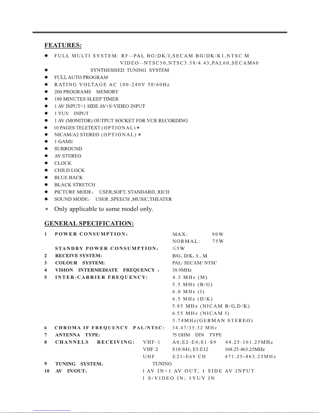
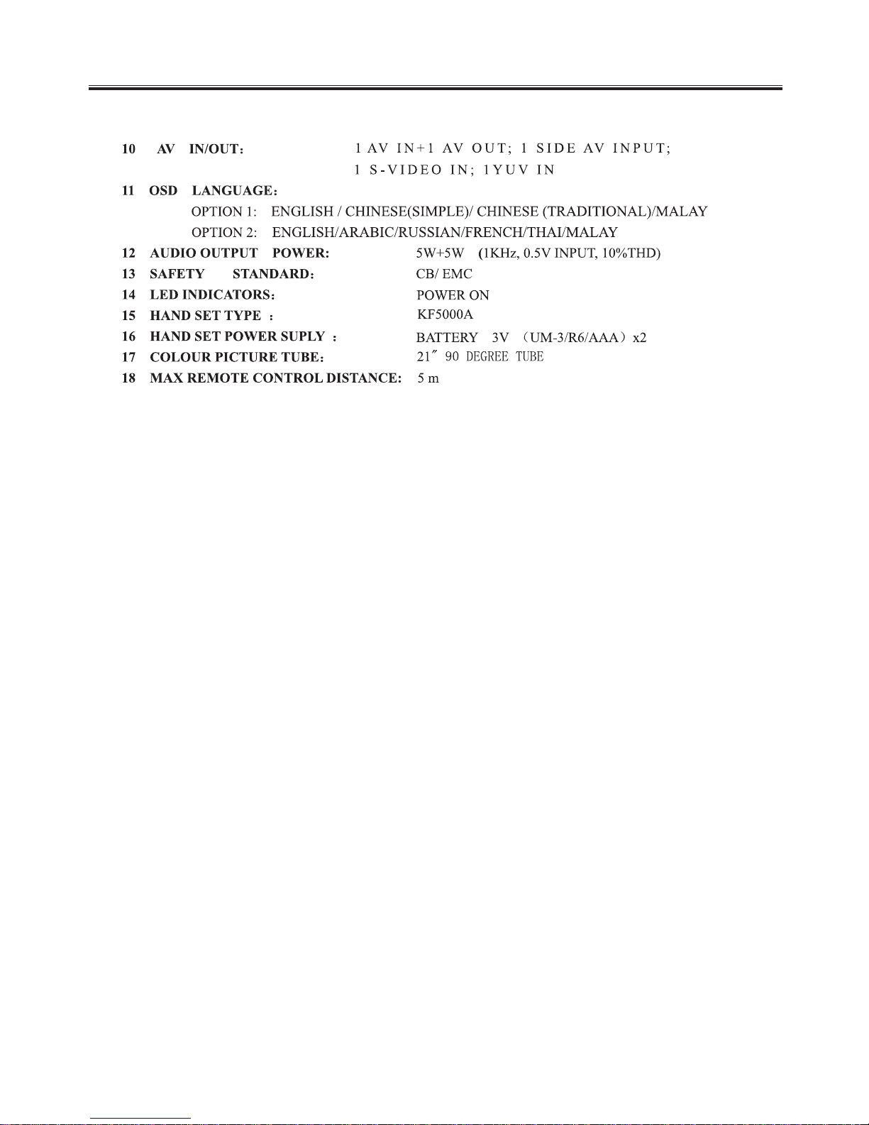
TECHNICAL SPECIFICATION
FREQUENCY
FS
-4-
TECHNICAL SPECIFICATION
E
-5-
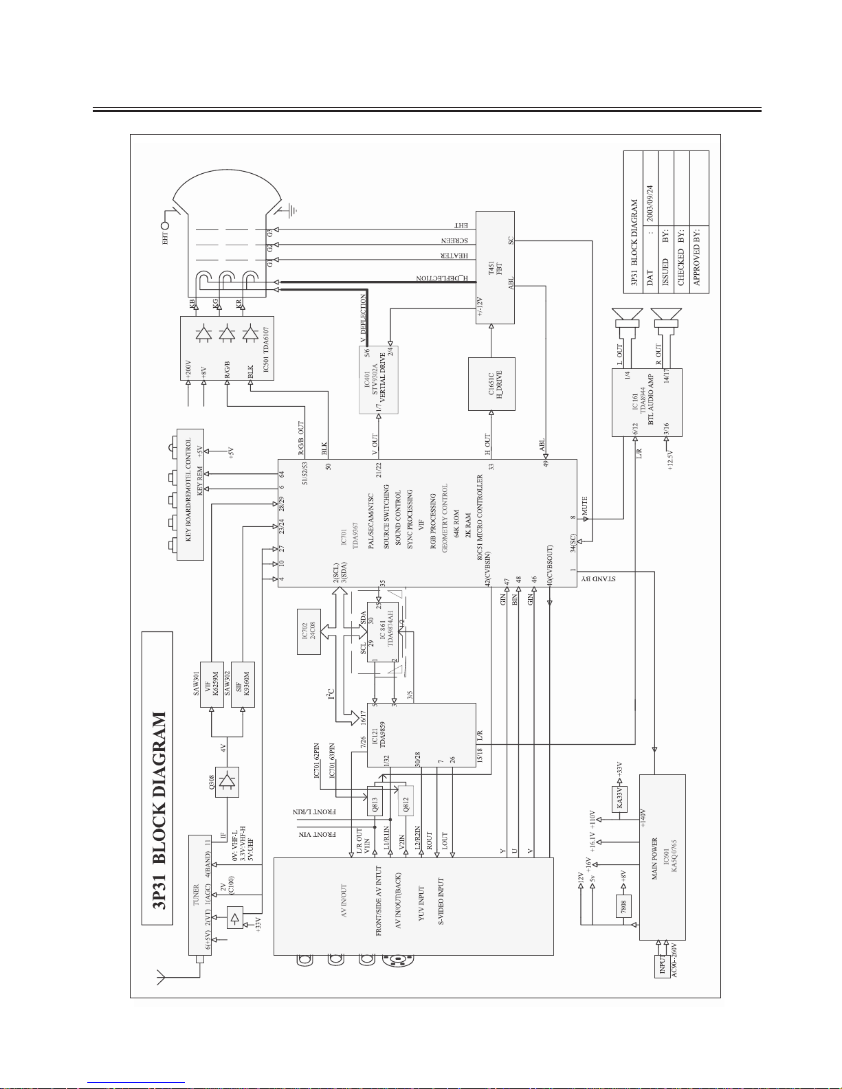
CHASSIS BLOCK DIAGRAM
-6-
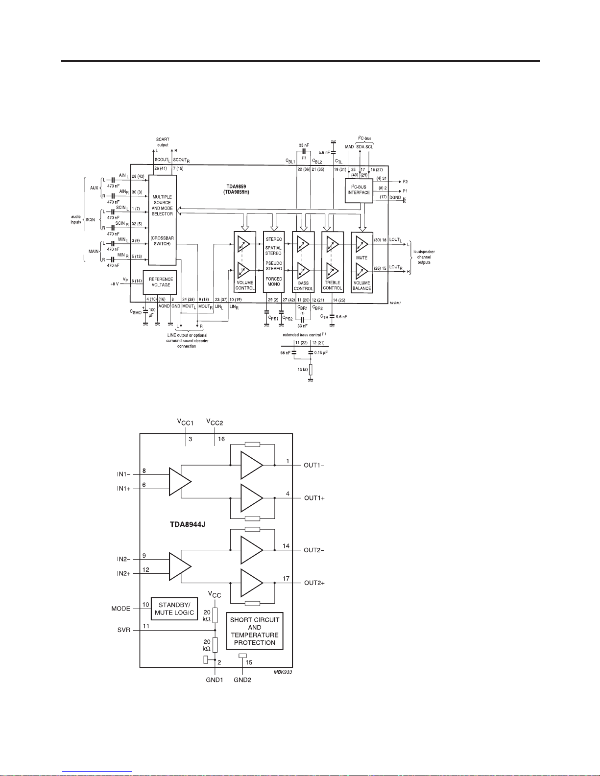
IC 121 (Universal HI-FI Audio Processor) TDA9859
IC BLOCK DIAGRAM
IC 161 TDA8944J(BTL Audio Amplifier)
-7-
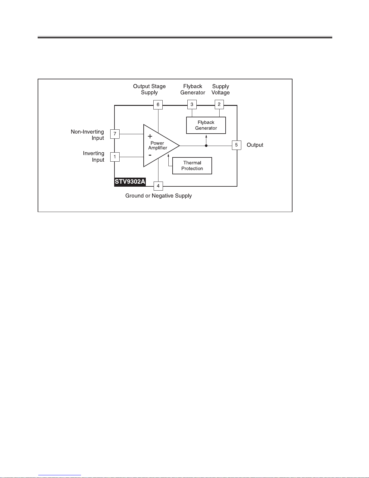
IC 401 (Vertical Deflection Booster) STV9302A
IC BLOCK DIAGRAM
-8-
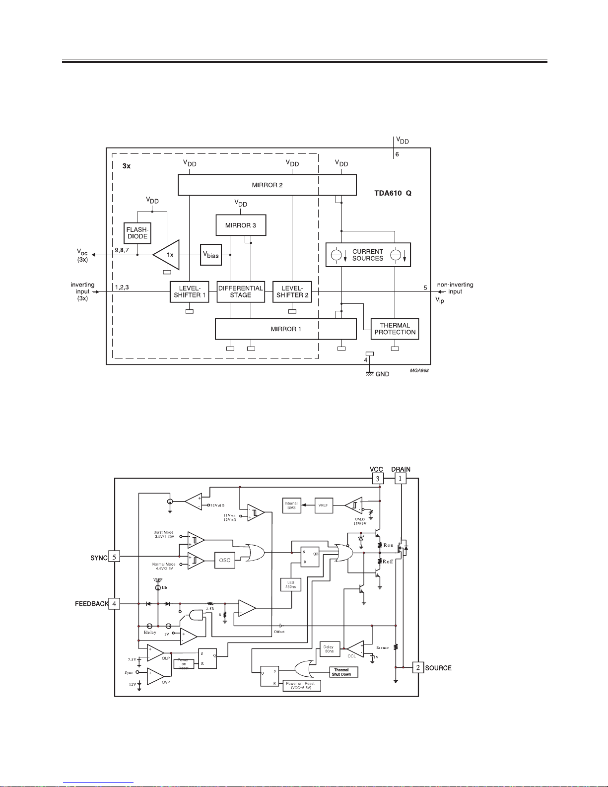
IC 601 (Power Switch) KA5Q0765RTH
IC 501(Video Output Amplifier) TDA6107Q
IC BLOCK DIAGRAM
7
-9-
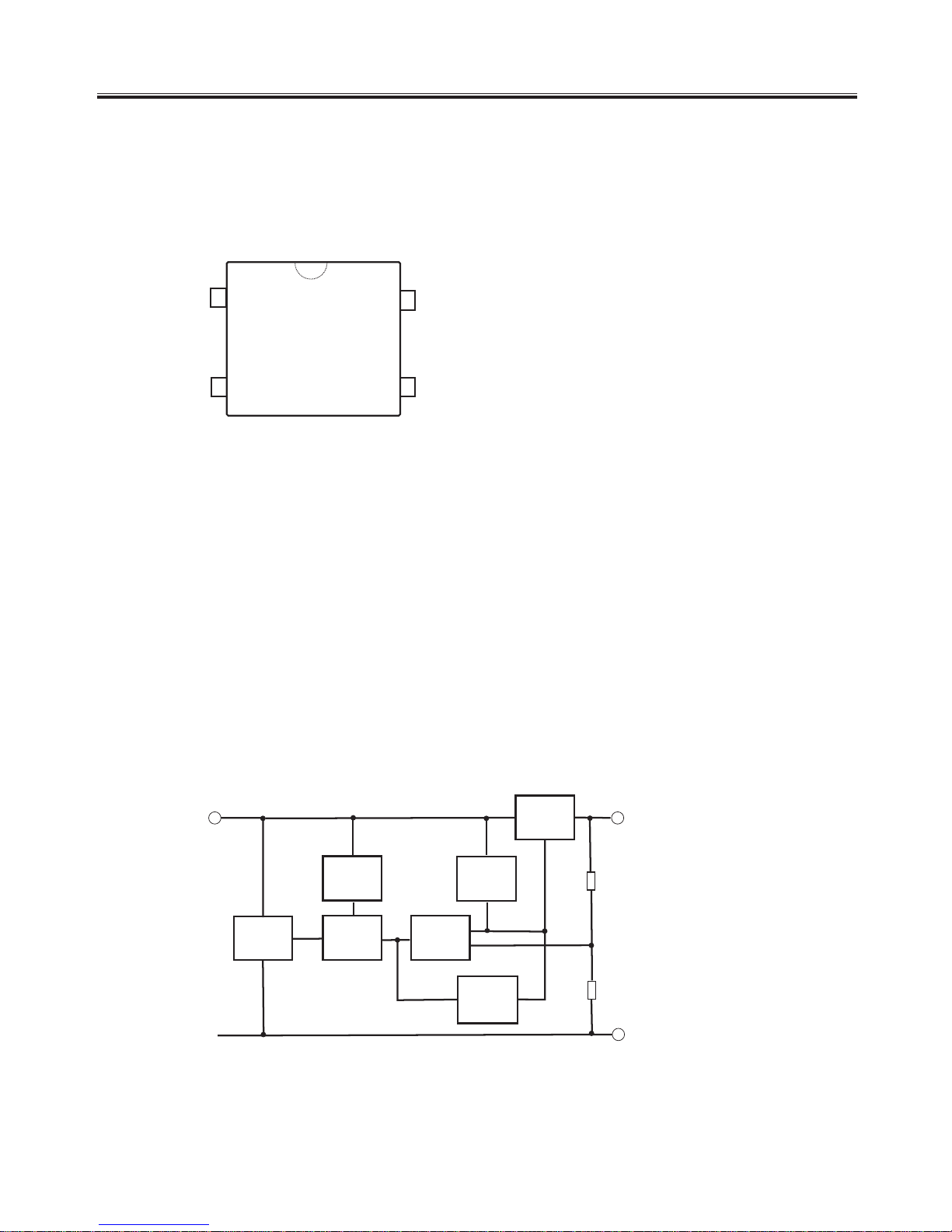
1
INPUT
2
OUTPUT
SERIES
PASS
ELEMENT
SOA
PROTECTION
REFERENCE
VOLTAGE
ERROR
AMPLIFIER
THERRMAL
PROTECTION
STARTING
CIRCUIT
CURRENT
GENERATOR
REFERENCE
VOLTAGE
3
GND
IC 653 & IC 181& IC 652 (Regulators) L7800 Series
1
2
3
4
1:ANODE
2:CATHODE
3:EMITTER
4:COLLECTOR
IC 602 (Photo Transistor ) TLP621
IC BLOCK DIAGRAM
TLP621
-10-
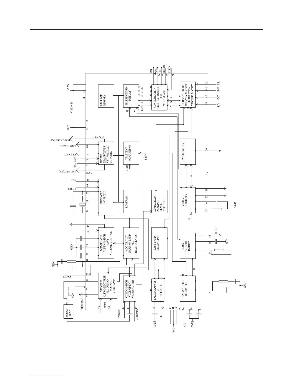
IC 701 ( TDA93XXPS/N2/5I TV Signal Processor-Teletext )
IC BLOCK DIAGRAM
-11-
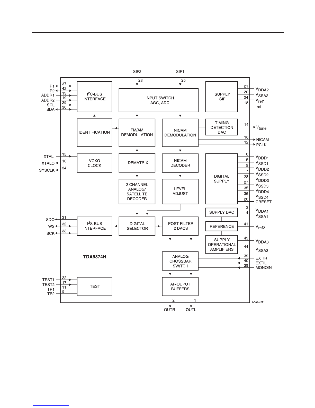
IC 861 ( TDA9874AH Digital TV Sound Demodulator/Decoder)
IC BLOCK DIAGRAM
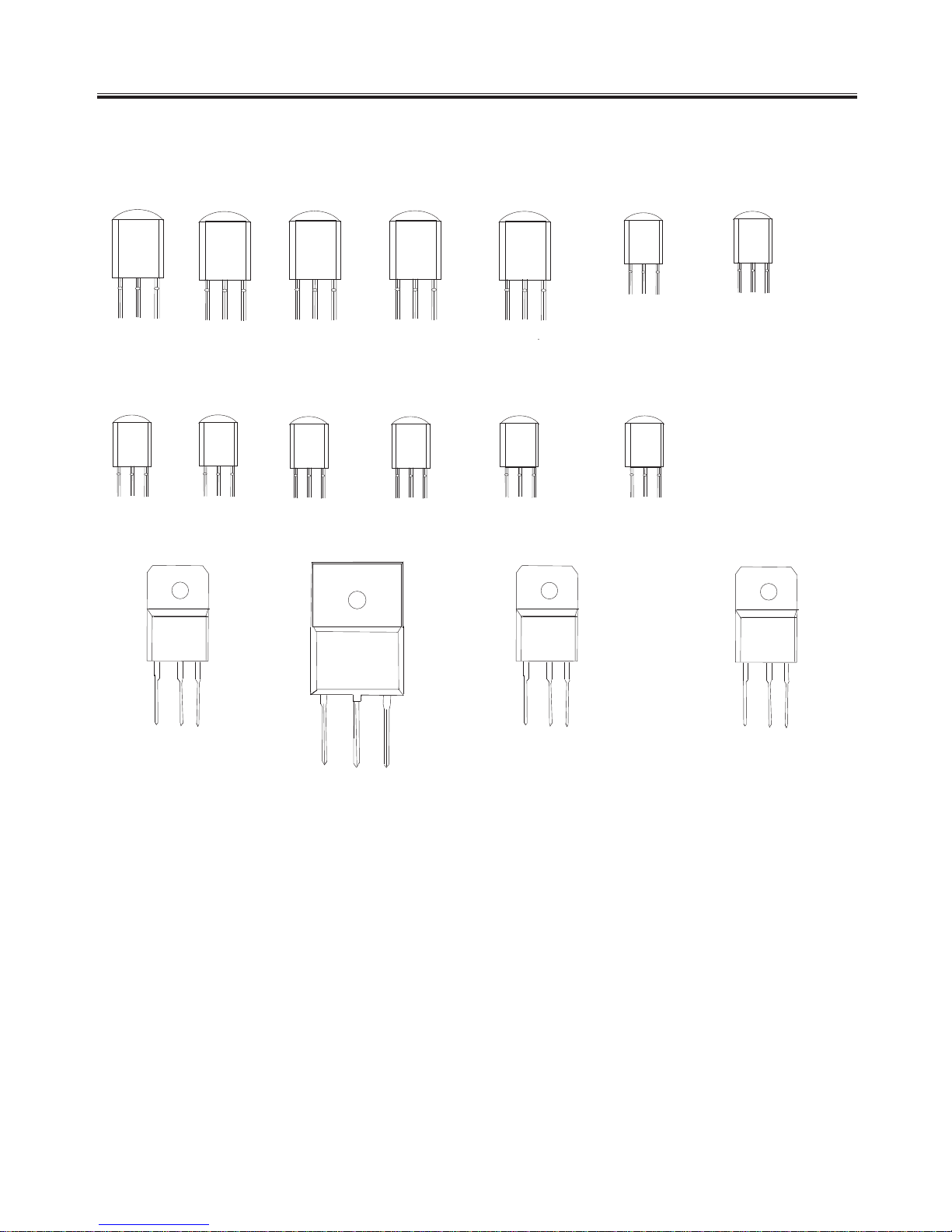
C1651C
B
C
E
C
B
E
C22
3
0
C
B
E
C
2
482
C
B
E
C270
3
C
B
E
C
1
8
1
5
C
B
E
B
4
2
1
C
B
E
C
B
E
A
1
0
1
5
PNP
B
7
7
4
C
B
E
PNP
NPN
B
4
2
0
C
B
E
NPN
PNP
C
2
1
2
0
C
B
E
PNP
C
2
2
1
6
C
B
E
NPN
C
2
7
1
7
C
B
E
NPN
L7805
INPUT
GND
OUTPUT
L7812
INPUT
GND
OUTPUT
L7808
INPUT
GND
OUTPUT
A10
1
3
NPN
NPN
NPN
PNP
-12-
C
B
E
A96
6
PNP
TRANSISTOR MARK
 Loading...