

Page 1

No. 0102
SERVICE MANUAL
MANUEL D'ENTRETIEN
WARTUNGSHANDBUCH
CAUTION:
Before servicing this chassis, it is important that the service technician read the “Safety
Precautions” and “Product Safety Notices” in this service manual.
ATTENTION:
Avant d’effectuer l’entretien du châassis, le technicien doit lire les «Précautions de sécurité»
et les «Notices de sécurité du produit» présentés dans le présent manuel.
VORSICHT:
Vor Öffnen des Gehäuses hat der Service-Ingenieur die „Sicherheitshinweise“ und „Hinweise
zur Produktsicherheit“ in diesem Wartungshandbuch zu lesen.
Model
C1422R/RS
C1422T/TS
C2122T
CP1422R
CP2122R
CP1422T/TS
CP2022T
CP2122T
CP1422T-481
CP2122T-481
CP1422T-491
CP2022T-491
CP2122T-491
CS1422R
CS2022R
CS2122R
CL1422R/RS
CL2122R
C1432TB/TY
CP1432RB
CP1432RY
Chassis
F1R
F1Y
F4Y
F1GR
F4GR
F1GY
F2GY
F4GY
F1HY
F4HY
F1HY
F2HY
F4HY
F1KR
F2KR
F4KR
F1FR
F4FR
F1R
F1Y
F1Y
TECHNICAL SPECIFICATIONS
SPÉCIFICATIONS TECHNIQUES SPECIFICATIONS TECHNIQUES
TV Standard.......................................625 lines,
STANDARD I (UK)
B/G/H/DK, L/L', (Export)
Channel coverage..............UHF Channels (UK)
UHF/VHF Hyper band (Export)
Aerial input impedance..........................75ohm
Unbalanced
Power Consumption.....................Picture Tube
14” Models < 40W 35.5cm types
20” Models < 48W 48cm types
21” Models < 52W 51cm types
Consumption in standby mode.................<4W
Mains Voltage........................220V/210V, 50Hz
Fuse..........................................2 Amp time-lag
Standard TV.....................................625 lignes,
STANDARD: R-U
B/G/H/DK, L/L': (Export)
Couverture de canaux.........Canaux UHF (R-U)
UHF/VHF Band hyper (Export)
Impédance d'entré e d' ante n n e............75 ohms
Non équilibrée
Consommation électrique.......... Tubes-images
14” Models < 40W 35.5cm types
20” Models < 48W 48cm types
21” Models < 52W 51cm types
Consommation en mode veille.................<4W
Tention secteur......................220V/240V, 50Hz
Fusible......................................2 Amp time-lag
Data contained within this Service
manual is subject to alteration for
improvement.
Les données fournies dans le présent
manuel d’entretien peuvent faire l’objet
de modifications en vue de perfectionner
le produit.
Die in diesem Wartungshandbuch
enthaltenen Spezifikationen können sich
zwecks Verbesserungen ändern.
Fernsehnorm....................................625 Zeilen,
Fernsehnorm I (nur GB)
Fernsehnorm B/G/H/DK, L/L’ (Export)
Kanäle..................................UHF-Bereich (GB)
UHF/VHF/Hyperband Bereich
Antenneneingangsimpedanz..............75 ohms
Unsymmetrisch
Leistungsaufnahme............................Bildröhre
14” Models < 40W 35.5cm types
20” Models < 48W 48cm types
21” Models < 52W 51cm types
Leistungsaufnahme im standby mode......<4W
Netzspannung.........................220/240V, 50Hz
Sicherung..................................2 Amp time-lag
SPECIFICATIONS AND PARTS ARE SUBJECT TO CHANGE FOR IMPROVEMENT
Colour Television
December 1998
Page 2

2
Page 3

ENGLISH
SAFETY PRECAUTIONS
WARNING: The following precautions must be observed.
ALL PRODUCTS
Before any service is performed on the chassis an
isolation transformer should be inserted between the
power line and the product.
1. When replacing the chassis in the cabinet, ensure
all the protective devices are put back in place.
2. When service is required, observe the original
lead dressing. Extra precaution should be taken to
ensure correct lead dressing in any high voltage
circuitry area.
3. Many electrical and mechanical parts in
HITACHI products have special safety related
characteristics. These characteristics are often not
evident from visual inspection, nor can the
protection afforded by them necessarily be
obtained by using replacement components rated
for higher voltage, wattage, etc. Replacement
parts which have these special safety
characteristics are identified by marking with a
! on the schematics and the replacement parts
list.
The use of a substitute replacement component
that does not have the same safety characteristics
as the HITACHI recommended replacement one,
shown in the parts list, may create electrical
shock, fire, X-radiation, or other hazards.
4. Always replace original spacers and maintain lead
lengths. Furthermore, where a short circuit has
occurred, replace those components that indicate
evidence of overheating.
5. Insulation resistance should not be less than 2M
ohms at 500V DC between the main poles and
any accessible metal parts.
6. No flashover or breakdown should occur during
the dielectric strength test, applying 3kV AC or
4.25kV DC for two seconds between the main
poles and accessible metal parts.
7. Before returning a serviced product to the
customer, the service technician must thoroughly
test the unit to be certain that it is completely safe
to operate without danger of electrical shock. The
service technician must make sure that no
protective device built into the instrument by the
manufacturer has become defective, or
inadvertently damaged during servicing.
CE MARK
1. HITACHI products may contain the CE mark on
the rating plate indicating that the product
contains parts that have been specifically
approved to provide electromagnetic
compatibility to designated levels.
2. When replacing any part in this product, please
use only the correct part itemised in the parts list
to ensure this standard is maintained, and take
care to replace lead dressing to its original state,
as this can have a bearing on the electromagnetic
radiation/immunity.
PICTURE TUBE
1. The line output stage can develop voltages in
excess of 25kV; if the E.H.T. cap is required to be
removed, discharge the anode to chassis via a
high value resistor, prior to its removal from the
picture tube.
2. High voltage should always be kept at the rated
value of the chassis and no higher. Operating at
higher voltages may cause a failure of the picture
tube or high voltage supply, and also, under
certain circumstances could produce X-radiation
levels moderately in excess of design levels. The
high voltage must not, under any circumstances,
exceed 29kV on the chassis (except for projection
Televisions).
3. The primary source of X-radiation in the product
is the picture tube. The picture tube utilised for
the above mentioned function in this chassis is
specially constructed to limit X-radiation. For
continued X-radiation protection, replace tube
with the same type as the original HITACHI
approved type
4. Keep the picture tube away from the body while
handling. Do not install, remove, or handle the
picture tube in any manner unless shatterproof
goggles are worn. People not so equipped should
be kept away while picture tubes are handled
LASERS
If the product contains a laser avoid direct exposure to
the beam when the cover is open or when interlocks are
defeated or have failed.
3
Page 4
SAFETY AND ISOLATION
1. Under no circumstances should any form of repair or maintenance be attempted by any person other than a
competent technician or engineer. The following precautions should be observed:
2. For purposes of servicing, the chassis should be supplied from an isolation transformer of at least 150W rating.
3. If disturbed, the original lead dressing should be restored. This is particularly important due to the 'hot coil'
nature of the chassis. Lead dressing will also have a bearing on the EMC performance of the chassis.
4. Components marked ! on the circuit diagram are safety approved types and have special safety related
characteristics. Only the manufacturers replacement components should be used. Replacement with alternative
or 'up-rated' parts e.g. higher power resistors definitely does not guarantee the same level of protection and
may create a fire, electric shock or X-radiation hazard.
5. Components not bearing the ! mark should still be replaced with the originally fitted type and should be
mounted in the same way.
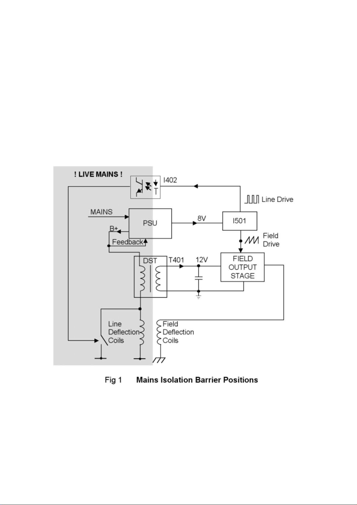
The Isolation Barrier
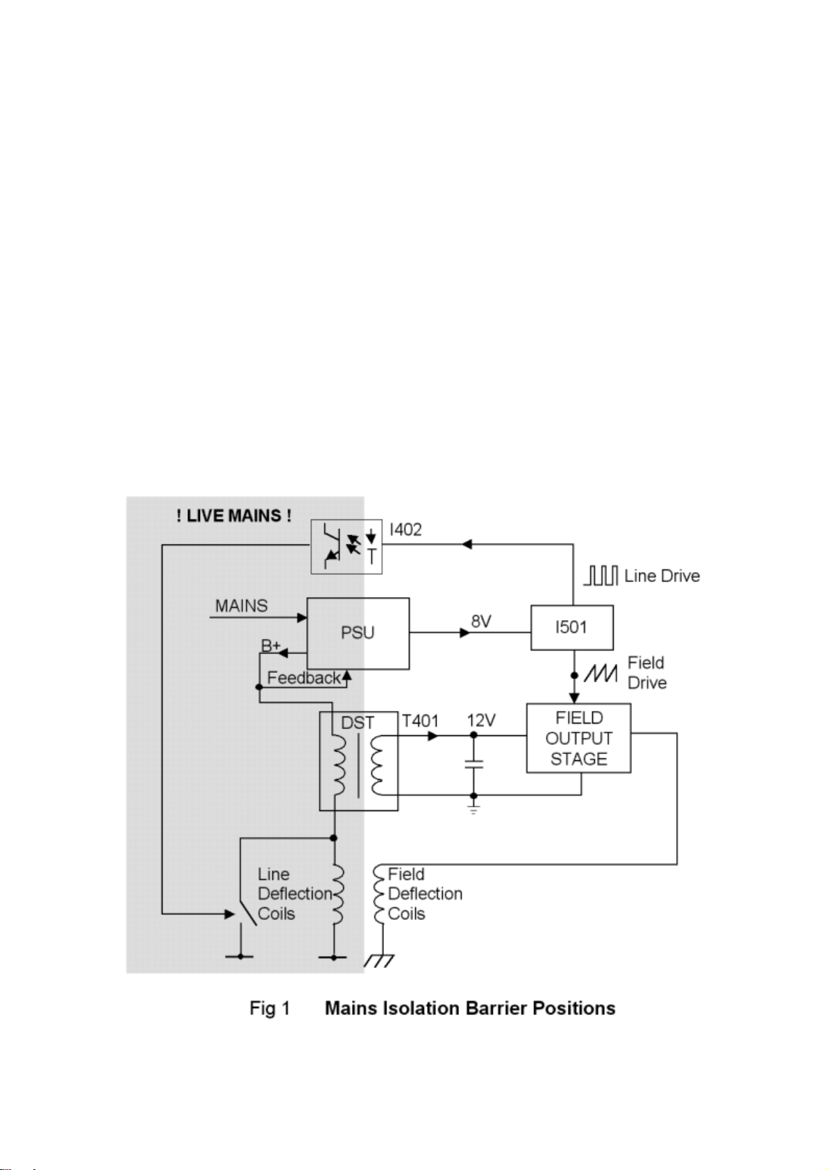
The chassis is a 'hot-coil' chassis whereby the line deflection coils are NOT isolated from the mains since the PSU does
not provide B+ rail isolation. Consequently, the mains isolation barrier is more convoluted than in a conventional
chassis and a much larger portion of the chassis is non-isolated. Figure 1 shows the isolation barrier position in the
chassis.
It can be seen that both the DST (T401) and the scan coils now straddle the isolation barrier and are, as such, safety
critical components. Also, the opto-coupler (I402) is required to pass line drive from I501 on the 'cold' side to the line
drive stage on the 'hot' side. The isolation barrier therefore consists of T802, T401, I402, C804, R804, R805, the scan
coils and 6mm air gaps. To maintain barrier integrity care should be taken not to reduce any air gaps, e.g. by protruding
wires, following component replacement. Deflection yoke lead dressing is important to maintain double insulation
across the isolation barrier. The position of the deflection lead sleeving is maintained by a tie wrap. Should this be
removed for any reason, the sleeving should be slid towards the deflection yoke and tie wrapped into position.
Semiconductor Device Handling Precautions
The chassis contains devices which may be damaged by static electrical charge during handling, particularly I501, I602,
I701 and Q801. To avoid damage, soldering irons should be earthed and service engineers should ideally wear wrist
straps earthed through a 1M resistor or at least discharge themselves to an earthed point.
4
Page 5

ERVICING
S
Microprocessor Control System
Microcontroller
Micro-controller, I701, is either a SAA5288 (on non-teletext sets) or a SAA5290 (on teletext sets). Both
devices have integrated on-screen display (OSD) generator; the SAA5290 also has an integrated teletext
decoder. The micro-controller has a single 12MHz crystal X701.
The television is controlled by serial (I²C) bus communication, digital switching inputs and outputs, analogueto-digital inputs and pulse-width-modulation (PWM) outputs.
Reset
At power on, C709 is not charged so the voltage on pin 43 of the micro-controller rises with the 5V supply
and resets the micro-controller. An internal resistor to ground at this pin causes C709 to charge up and the
voltage on the reset pin to drop to 0V.
In normal operation, transistor Q702 is switched on and the reset pin is low, but if the 10V supply voltage
drops below about 8V the transistor will switch off and R721 will pull the reset pin high and reset the device.
User Control
User input is via infra-red remote control (Philips' RC5 protocol), internally decoded from the receiver I703,
or from three (non-matrixed) local control keys on active low inputs, I701 pins 18, 19 and 20. The LED
flashes each time a key is detected or remote command received.
Tuning
The tuning control voltage to the tuner is controlled via the PW M at pin 1 of I701 and integrating circuit
around Q001. Minimum voltage is at maximum mark-space ratio (bottom of each band). Band-switching is
controlled by active low outputs on pins 14, 15 and 16 (high, mid, low) and transistors Q002 to Q004. The
controller makes AFC corrections by reading on-tune information from I501 via the I²C bus.
As the tuner is controlled by voltage synthesis, there is no direct correlation between the controller output
and the tuned frequency.
Non-volatile memory
The non-volatile memory, I702, holds configuration information, user settings, parameters as applicable for
I²C controlled ICs and the programme tuning records. It is itself accessed by I²C.
When a new memory IC is fitted, the microcontroller will automatically load default information, which takes a
few seconds during power-up. Regular re-loading of the data, or corruption of settings may indicate I702 is
faulty.
AV switching
Inputs from pins 8 and 16 of SCART 1 are sampled by analogue to digital conversion on pins 9 and 10 of
I701 respectively. The input levels are adjusted such that the controller will automatically switch to AV1
when pin 8 is above 6V and RGB when pin 16 is above 1V. The time constant on pin 16 ensures the
controller will not detect real-time RGB insertion using pin 16.
OSD / Teletext
Line and field timings are obtained from V.sync on pin 37 and H.sync input on pin 36. Teletext (on teletext
sets only) is obtained from the CVBS input on pin 23. The RGB outputs on pins 34, 33 and 32 respectively
are inserted into the TV output when gated by the OSD EN OUT signal on pin 35. OSD / teletext contrast is
controlled by the peak reference level on pin 31, generated from the microcontroller PWM output on pin 2 via
Q305.
Error codes
Under the following fault conditions the television will switch to standby and flash the LED.
5
Page 6

Fault Condition No. of Flashes
Multiple TDA884X I²C errors 1
Over voltage / X-ray protection (OVP) 2
Line start-up sequence failed 3
Black current (BC) loop unstable 4
Vertical scan failure 5
Continuous TDA884X power-on reset 6
Multiple error codes may appear, eg. two quick flashes, pause, four quick flashes etc. for OVP + BC loop
errors.
Adjustments
In order to make service adjustments including setting the height, width, various configuration options, etc.,
the TV should have a suitable signal tuned in; ideally, a geometry test card. A teletext signal is
recommended for setting OSD contrast on a teletext chassis.
To enter service mode, place a shorting link across terminals 2 and 3 of P701.
In service mode, two 2-digit hexadecimal numbers are displayed to the left of the screen; the lefthand one is
the service parameter number, the righthand one is the value for that parameter. Some parameters are
identified by a two-letter code instead of a number, see below.
For example:- 0A 1F shows parameter ten (0A hex) at thirty-one (1F hex).
In this mode of operation some of the remote control keys have different functions;
The up and down and local select keys are used to select a parameter.
The remote and local left and right keys are used to change the value of the current parameter.
The TV button is used to store any changes.
The teletext select and digit '0' keys are used for programme up or down.
The Normalize key selects factory picture settings immediately over-writing user settings.
The digit keys '1', '2',----'8' toggle the state of the individual bits '7', '6',----'0' of the value of the current
parameter, for example, pressing digit key '4' would change value 1F hex to 0F hex.
TO STORE THE CHANGES, PRESS THE TV KEY ON THE HAND UNIT BEFORE REMOVING THE
SERVICE MODE LINK. THE MESSAGE 'STORED' WILL BE DISPLAYED TO CONFIRM THE
OPERATION.
Under certain circumstances, for example abnormal operation due to suspected corruption of the service
parameters, it may be necessary to perform a complete reset of the non-volatile memory (I702). To effect
this, press and hold the X (teletext update) key for about 3 seconds or until the set switches to standby.
Following this it will be necessary to perform a 'set-up' of the television.
Service Parameters
The following values assume you are watching a tuned in picture, on RF. (On other sources, or with no
signal, some values may differ.)
Service parameters 00 to 1A apply to the control registers of I501 as shown in the following table.
No. Value Function Action
00 02 02 02 System Control Do not adjust
01 D0 D0 D0 System Control Do not adjust
02 1F 1F 1F Hue (SCART NTSC 4.43 playback only) Use picture menu control instead
03 20 1D 27 Horizontal shift Adjust to centre picture horizontally
04-07 00 0 0 00 E-W control Not used on this chassis
08 20 1F 1E Vertical slope (linearity) Adjust for vertical linearity
09 10 0B 1A Height Adjust for correct picture height
0A 44 4A 4A S-correction Adjust for best vertical S-correction
14" 20" 21"
6
Page 7
No. Value Function Action
0B 2B 1B 1B Vertical shift Adjust to centre picture vertically
0C 29 38 3D White point - Red
0D 29 38 3D White point - Green
0E 29 38 3D White point - Blue
0F 1C 1C 1C Peaking (sharpness) Use picture menu control instead
10 5C 5C 5C Brightness Use picture menu control instead
11 9C 9C 9C Saturation Use picture menu control instead
12 1C 1C 1C Contrast Use picture menu control instead
13 13 13 13 AGC take-over point
14 0A 0A 0A Volume
15 50 50 50 IF PLL adjustment Set to 50 hex
16 19 19 19 Vertical zoom Not used on this chassis
17 20 20 20 Vertical scroll Not used on this chassis
18 81 81 81 Control 2 Do not adjust
19 08 08 08 Control 3 Do not adjust
1A 00 00 00 Control 4 Do not adjust
14" 20" 21"
See "Adjustments" in Servicing
See "Adjustments" in Servicing
Service Parameter Functions
Parameters above 1A are designated by two-letter codes (except text contrast on a teletext set). These
control configuration.
Text Mode Text (OSD) contrast Set as preferred, see notes below
Ex Export (VHF/UHF) setting 00 for UHF-only, 01 if multi-band tuner
AV AV socket configuration 00 single SCART, 01 single SCART plus phono inputs
It is advisable to make a note of the existing values prior to commencing servicing. (see "Adjustments" in
Servicing)
7
Page 8

Adjustments
H. T. Setting
The HT should be adjusted using R818 to obtain correct width with normal brightness and contrast settings.
A Philips complex test pattern is ideal for the operation.
A1 Control
This should be set using the ‘screen’ control on T401 to achieve 140V black level at the tube base cathodes
with the brightness and contrast settings normalized. In practice the black level of the individual guns will
differ and are set by I501 to achieve equal cut-off points.
White Points
These should be adjusted via service parameters 0C, 0D and CE whilst viewing a picture with little light area
to prevent beam current limiting. The parameters should be adjusted for a black to white swing of 50V ±1V
(14”), 55V ±1V (20”) or 60V ±1V (21”) on each of the three cathodes with the picture normalized.
Text Contrast
White balancing of the red and blue outputs, relative to the green, should be carried out to ensure pure white
text, using RV317 (R) and RV319 (B). As the picture outputs are automatically balanced, text white may be
set using picture white as a reference once the black and white points (See adjustments section) have been
set. The text contrast itself should be adjusted such, that the Text/OSD white parts are approximately 75% of
the intensity of a test pattern peak white area: this corresponds to the 75% grey blocks in part of a ‘Philips
5544’ type test pattern. When the text contrast service parameter is selected the TV switches to teletext mix
mode, page 101. If no text is present P100 will still appear in the top left corner of the screen together with
some text on the bottom row of the display. There is no on-screen parameter: adjust with volume control as
normal and change parameter with programme up/down keys.
AGC
The AGC take-over point should be adjusted via service parameter 13 such, that the tuner output to the
SAW filter is 600mV pk-pk (300mV per side for symmetrical tuner output) using a test pattern with no sound
carrier.
Focus
Adjust the upper control on the rear of the flyback transformer for best focus.
Positioning
Horizontal position should be adjusted via service parameter 03 so as to centre the picture. Vertical position
should be adjusted via service parameter 0B so as to centre the picture. This may be simplified by pressing
‘1’ with service parameter 0B selected to activate service blanking which blanks the lower half of the picture.
The edge of the blanked area may then be aligned with the tube centre marks. Service blanking is disabled
by once again pressing the ‘1’ key.
Linearity
Horizontal linearity is fixed; no adjustment is possible. Vertical linearity is adjusted using service parameters
08 and 0A (linearity and S-correction) whilst displaying a cross hatch pattern. Adjust the linearity for evenly
spaced intervals at the top and bottom of the picture, then adjust the S-correction to achieve equal spacing
accross the whole screen.
Vertical Protection Disable
Vertical protection is used to shut down the chassis in the event of field-scan failure. For diagnostic purposes
this can be disabled by selecting service parameter OA (S-correction) and pressing the number 2 key on the
8
Page 9

hand unit. After repair, vertical protection should always be re-enabled by pressing the number 2 key again
and storing it with the TV key. (The value of parameter OA toggles between two values when the number 2
key is pressed,
the higher
of which indicates that the vertical protection is
enabled
.).
Auto Black Level Disable
I501 independently sets the black level of each CRT gun to equalize the cut-off points and therefore provide
a true black. For diagnostic purposes this control loop may be disabled by selecting service parameter 02
(hue) and pressing the number 2 key on the hand unit. After repair, the auto black level sampling should
always be re-enabled by pressing the number 2 key again and storing it with the TV key. (The value of
parameter 02 toggles between two values when the number 2 key is pressed,
black level sampling is
enabled
).
the lower
of which indicates
Adjustment Locations (Physical)
See adjustment locations PCB
9
Page 10
IRCUIT DESCRIPTION
C
Switched Mode Power Supply
Summary
The power supply is a self-oscillating discontinuous buck converter (step-down chopper) under peak current
control and designed for up to 65W output power at nominally 98V. The main B+ output of this converter
topology is inherently non-isolated and as such, output voltage feedback does not require an opto-coupler.
Some energy is derived in flyback mode via an isolated winding on the buck inductor to provide a low power
10V secondary supply from which are derived switched 8V (video processor) and permanent 5V (µP)
supplies.
In stand-by mode, both the B+ and 10V supplies remain close to their nominal operating levels but with
virtually zero load, the PSU enters a burst-mode whereby typically 180 in 200 cycles are skipped. In this way,
the stand-by power consumption (including degaussing circuit) is less than 4W.
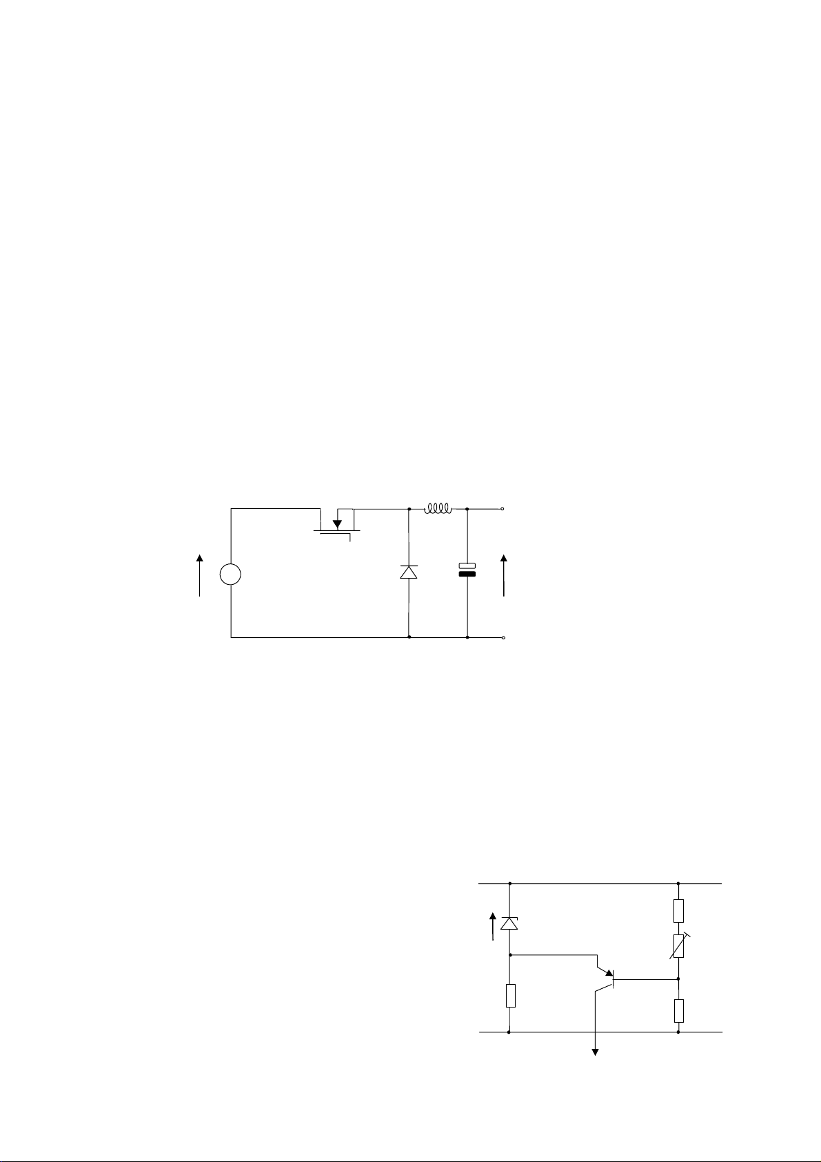
Description of Operation of the Buck Converter
Figure 4 shows the main components of the buck converter. The output voltage may be controlled between
zero and the input voltage by varying the on-time of Q801. During this period, Vin-Vout is applied across the
buck inductor (T802 winding pins 7 & 8) and the current in it ramps up linearly. When Q801 is turned off, Vout is applied across the buck inductor and energy is delivered to the load and C809 combination.
280 - 390
T802 (pins 7 & 8)
Q801
V
IN
Fig 4
The Buck Converter Topology
D804
C809
V
OUT
(100V)
Start-Up
At start-up, the overwind output voltage (T802 winding pins 7 & 8) is not present so a start-up bias circuit is
required. This consists of R806, D802 and R809. Approximately 16V is produced at the junction of R806 and
D802 which is fed via R809 to turn on Q801 for the first time.
Control Method
During the on-time of Q801, the buck inductor voltage flows through the current sense resistor R814 forming
an analogue of the buck inductor current. This is fed to the base of Q802 along with a DC bias current from
the error amplifier (via R813) such that once a certain buck inductor current level is reached, Q802 turns on.
When this happens Q801 is turned off and the inductor current free-wheels through D804. This is peak
current-mode control.
Output Voltage Regulation
The non-isolated B+ rail means that no opto-isolator is
required for direct Vo control. It can be seen from Figure 5 that
Vo minus a small zener voltage drives the emitter of this
transistor (Vo-Vz) whilst a resistive potential divider feeds the
base (kVo, k<1). If, for instance, the output voltage tends to
rise, Ve rises by ∆Vo whereas Vb only rises by ∆kVo. The net
result is an increase in negative bias and an increase in
collector (control) current. R818 in the potential divider
provides an element of control over the B+ voltage.
Vz
R815
D806
Fig 5
Ve
Vb
Control Current
The Error Amplifier
R817
R818
kVo
R820
10
Page 11
Overvoltage Protection
An unfortunate characteristic of the buck converter is that if the power switch Q801 should become shortcircuit, the full rectified mains voltage appears at the output, over stressing components in both the PSU itself
and the load. In order to limit the output voltage rise under these conditions, a 130V 5W zener diode D805 is
fitted across the B+ output. An over-voltage causes conduction of D805, shorting the B+ output and blowing
the fuse F801.
Isolated Supplies
In order to provide low voltage isolated supplies, a secondary winding is included on the buck inductor,
phased such that energy is delivered in flyback mode, that is when Q801 is off. During this interval, the buck
inductor voltage is clamped to the output voltage and the turns ratio is chosen to provide a secondary of 10V
with rectification and smoothing performed by D807 and C812 and overload protection by R821. A
permanent 5V µP supply is derived from this 10V supply by I801 as well as an 8V switched supply under µP
control by Q804, R822, D808 and Q805.
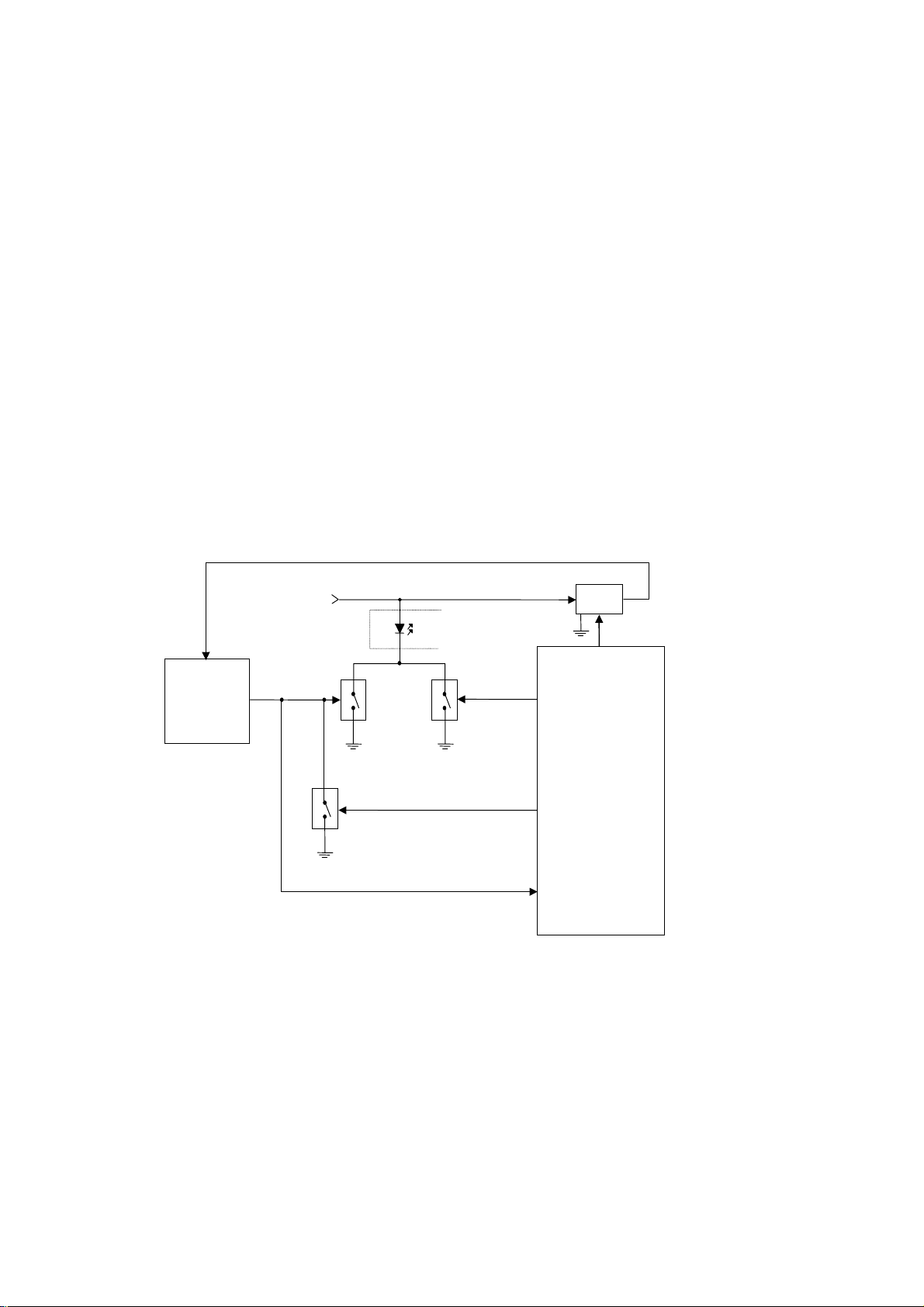
Chassis Start-Up Procedure
The PSU topology used in the chassis has a characteristic which complicates start-up. Until a B+ load is
established (i.e. the line output stage starts), the isolated secondaries are very high impedance - simply
turning on the video processor 8V supply and waiting for line-drive to start-up would fail since the supply
cannot deliver I501's supply current. In order to overcome this problem, a system of 'pseudo line-drive' was
devised which allows the line output stage to be driven by the µP in order to establish a B+ load prior to turnon of the video processor 8V supply. Figure 6 is a block representation of this system.
8V
10V from PSU
I402
12, 37
I501
True Line
H
OUT
40
Fig 6
Start-up Circuit Block Diagram
Q402, R423
Q405, R422
Q406, R427
30
47
7
Pseudo
Line
Drive
True Line
Drive
Gating
True Line
Drive
Detection
8V
48
8V Control
I701
Q804, R822, D808, Q805
The two line drive sources are OR-ed together at the input of I402, the two driver transistors being Q402 and
Q406. The µP is responsible for ensuring that both line drive sources cannot drive the output stage
simultaneously and to achieve this, the true line drive from I501 is monitored (µP pin 47). In this way, the
transition from pseudo to true line-drive is timed to the latter starting up. However, the line-drive stage does
not reliably operate at 31kHz so the soft-start cycle of I501 must be gated out. The µP achieves this by
keeping Q405 on for a fixed time after true line-drive has been detected thus keeping Q402 off. When this
time has elapsed, pseudo line-drive is stopped and Q405 turned off simultaneously, completing the start-up
sequence.
On reverting to stand-by pin 7 reverts to the high state which maintains I402 in conduction via Q406. This
maintains Q403 on and the line output transistor (Q404) off.
11
Page 12

Tuner and IF Stages
Tuner
The main chassis is fitted with a voltage synthesis UHF tuner for system I. Control of the tuned frequency is
achieved by a voltage on pin 2 of the tuner. This voltage is derived from integrating a 33 volt PWM switched
waveform. This PW M waveform is derived from pin 1 of the microcontroller I701.
The AFC is sampled by the microcontroller via the I²C bus from I501 and frequency correction is achieved by
microcontroller adjustment of the duty cycle of the PWM which then modifies the tuner frequency.
AGC Adjustment
For most aerial input signal levels the tuner operates at maximum gain. At high signal levels the gain of the
tuner is reduced by an AGC voltage generated in the IF stage. The AGC output from the IF (pin 54 of I501) is
applied to pin 1 of the tuner (H001).
The AGC maintains a maximum IF voltage of 600mV peak to peak. The voltage level can be adjusted using
the following procedure:
Short circuit pins 2 and 3 of P701 to enter service mode. When in service mode use the programme up and
down keys to select service parameter 13. Using a 40MHz or greater oscilloscope, monitor pin 11 of TU001.
Adjust service parameter 13 using the volume up and down keys for 600mV on pin 11 for a single ended
tuner, and 300mV for a differential output tuner. Press the RV key to store the AGC value.
AFC Adjustment
The AFC voltage is not available at any point on the chassis; it is read by the microcontroller via the I²C bus.
Therefore, one of the following methods can be used to correctly align the AFC.
a) For demodulator tank coil fitted (I501 = TDA884X Mask 1)
Tune a known channel. Using a spectrum analyzer monitor pin 11 of H001. Fine tune the tuner for a
carrier frequency of 38.9MHz. Store the fine tuned frequency (i.e. AFC off). Enter service mode by
applying a short circuit to pins 2 and 3 of P701. When in service mode use the programme up and
down keys to select service parameter 15. Adjust service parameter 15 using the volume up and
down keys until the two bits at the top right of the screen meet the following criteria:
Left hand bit permanently set.
Right hand bit toggles (either 1 to 0 or 0 to 1).
When the AFC value has been set press the TV key to store it.
b) For demodulator tank coil not fitted (I501 = TDA886X Mask 2)
Adjust service parameter 15 using the volume up and down keys until its value is 50.
When the AFC value has been set press the TV key to store it.
Vision Decoding
The majority of the vision and sound, deflection and colour decoding is performed by I501. The IF signal
passes from the tuner through the SAW filter (X001) to filter unwanted frequencies to I501. It is demodulated
internally and the output at pin 6 is buffered by Q501. The sound and vision components are now separated.
Z501 removes the sound from the vision components and Z601/602 filters the FM sound to pin 1 for
demodulation. Video is then fed to the SCART socket output, pin 19 of P501 via Q502.
12
Page 13

Source Selection
Source selection is controlled by the microcontroller via I²C bus commands. The video processor I501 can
select between internal demodulated CVBS video on its pin 13, external CVBS video (AV1) from pin 20 of
P501 on its pin 17 or, if available, from external CVBS video (AV2) from the yellow phono socket of PA501,
which is applied to pin 11. The internally demodulated CVBS video is always available on pin 19 of P501.
External RGB is selected within I501. Fast blanking pulses from pin 16 of P501 are passed via an OR-ing
circuit of Q301-304 and associated components to pin 26 of I501. This pin controls the state of the RGB
outputs to the tube base pins 19, 20 and 21. It has three possible states:
1) Less than 0.4V Internal RGB from colour decoder.
2) Between 0.4V and 4.0V External RGB from pins 7, 11 and 15.
3) Greater than 4V Output blanked for OSD/Text insertion.
When teletext or OSD is displayed, pin 35 of I703 goes from ground to 5.0 Volts. This signal is passed via
Q301 and causes pin 26 of I501 to enter the third state above, independent of the state of the other inputs to
the OR circuit. During mixed TV/Text mode or whilst the OSD is showing on part of the screen this line will
be switching at a high rate. RGB mode can be selected manually by the user and in this case the open-drain
output on pin 8 of the micro-controller will be switched off and will be pulled up to 1.7 volts by R307 and
R306. Q302 then applies a voltage of about 1.0 volts to pin 26 of I501. In the absence of a higher voltage via
Q301 and Q303 from the fast blanking input, pin 16 of P501, this is still sufficient to enter the external RGB
mode.
Audio source switching is controlled via the microprocessor I701. The audio is switched from internal to
external source via I²C in I501. Internal source is fed to I501 at pin 1 and the external source at pin 2. On
models equipped with front AV, the external source is provided either from pins 2 and 6 of P501 or the white
phono socket PA501.The external source selection is controlled by pin 3 of I701 and Q703, then switched by
I602. On models without front AV, I602 is omitted and bypassed via R601. On models equipped with a
headphone socket, the speaker feed from the audio amplifier (I601) is diverted to the headphone when a
headphone jack is plugged into PA601.
13
Page 14

Colour Decoder
The luma signal processing and colour decoding are implemented by I501. The luminance and chrominance
signals are separated internally. A delay line is also incorporated to compensate for the difference between
the luma and chroma processing times. There are no adjustments required on the colour decoder.
On-Screen Display
The micro-controller on-screen display (OSD) supplies blanking and RGB signals for overlaying the
television picture. Pin 35 of I701 provides blanking pulses which are applied to pin 26 of I501 via Q301, to
turn off the decoder RGB output so that the OSD is clearly visible. The RGB signals from pins 34, 33 and 32
of I701 are applied directly to the tube-base via Q306 to Q308 and the text drive colour balance presents
R317 and R319.
14
Page 15

Horizontal and Vertical Deflection
In addition to decoding and switching, I501 provides deflection processing for the horizontal and vertical
time-base circuits. Using video from the IF or external source as appropriate, the timebase circuit of I501
produces horizontal drive pulses at pin 40 to switch horizontal drive transistor Q402, and a differential vertical
ramp at pins 46 and 47 to drive the vertical deflection output amplifier (I401).
All geometry adjustments are performed via the I²C bus with the service parameters (See adjustments
section) with the exceptions of picture width (which is fine tuned by adjusting the B+ voltage by means of
R818) and horizontal linearity (which is fixed by L402.)
Line Circuit
The primary side of the line circuit and the deflection coil are connected to the hot earth. The driver circuit
contains an opto-coupler to create isolation between the low signal parts and the mains. The opto-coupler is
driven by pin 40 of I501 via transistor Q402.
When Q402 is not conducting, the LED of the opto-coupler is also out of conduction, and Q403 is also not
conducting. In this way, Q404 will conduct and the B+ voltage (100V) is placed across winding 2-1 of the line
output transformer (T401). A voltage across winding 2-1 of the line output transformer (T401) will cause a
voltage across the windings 6- 9, 7- 9, 8- 9 and 10- 9. Energy is now transformed from the primary to the
secondary side and charges capacitors C407 (+200V video supply), C408 (+13V field supply) and C409 (13V field supply).
When transistor Q402 conducts, the LED of the opto-coupler is activated. This causes the transistor of the
opto-coupler to conduct, which drives Q403 into conduction. This brings Q404 out of conduction. Due to this
configuration, this circuit is protected against missing line-drive pulses. When a line-drive pulse is missed,
the line output transistor (Q404) stays out of conduction, because the LED of the opto-coupler is forced into
conduction by Q402 and R405 and R406. By this means, damage is avoided when there is no line drive.
The line output transistor Q404 is helped in its switching action by the extra winding 2-3 while C412 helps in
the switching action and prevents Q404 overheating.
C418 prevents Q404 from switching at twice line frequency. Line jitter is reduced by capacitor C417 in the
collector of Q402.
On the secondary side of the line output transformer (T401) there is a blanking circuit which consists of C749
and R734, D501, D502 and D503. As Q404 switches off this circuit sends a pulse to pin 41 of I501 via R532
to blank the picture.
Horizontal Deflection
The voltage across capacitor C809 is the same as the voltage between B+ and the hot earth. (100V) When
Q404 is conducting, this voltage is placed across the horizontal deflection coil via C411 and L402. This
causes a linearly increasing current through this coil, thus creating horizontal deflection. When Q404
switches off, horizontal flyback takes place and then horizontal deflection is repeated and so on. C411 and
L402 are used for linearity correction.
Vertical Deflection
Vertical deflection is based on a balanced input amplifier I401 connected to the +13V supply and -13V
supply. This is driven from pins 46 and 47 of I501 via R407 and R408. A negative going ramp at field rate
from I501 pin 46 is used to control I401. When the ramp is at its highest point, vertical flyback is generated
at I401 output (pin 5) by means of C403 and D411 and a flyback generator internal to I401. After vertical
flyback, the I401 output generates a negative going ramp across the field deflection coil which provides
deflection until the next flyback pulse and so on. R413 is used to damp oscillation of the field deflection coil.
Vertical deflection amplifier stability against self oscillation is maintained by R412, C404 and C402.
15
Page 16

Vertical Protection
When operating normally, the vertical output stage generates a +5.5V pulse during vertical flyback blanking.
This pulse is fed via Q407 to I501 beam current input. Should this pulse fail, the picture tube outputs are
"blanked off" until after about 12 seconds, the micro controller records a failure. For diagnostic purposes,
vertical protection during the 12 second interval may be disabled by pressing the '2' key on the remote
control handunit when in service parameter 'OA'. This should always be re-enabled after repair (See
adjustments section).
16
Page 17

TUBE BASE PANEL
The picture tube amplifiers produce high voltage CRT electrode drives from the low voltage RGB outputs of
the TDA884x (I501). They also produce black current information to maintain the grey-scale characteristics
which is returned to the colour decoder (I501). Also included is circuitry for picture blanking during switch on.
The picture tube aquadag, (P901), is used to provide beam current information for the colour decoder for the
purposes of beam current limiting. The tubebase socket (P902) is fitted with internal spark gaps. D910
provides tube base protection when the spark gaps flash-over.
The panel includes supplies to the tube electrodes and the video amplifiers. Focus and A1 supplies are
connected directly from the flying leads of T401.
Video Drives
All video drive adjustments are done via the I²C bus (See adjustments section) with the exception of the
black level set point (140V) which is set by the A1 control on the line output transformer (T401). An additional
feature for diagnostic purposes is the ability to disable the auto black level circuit by pressing '2' on the
remote control hand set when in service parameter 02 (See adjustments section)
Tubebase Video Amplifier Circuit
Each video amplifier channel includes a bipolar cascode amplifier. A R, G or B signal from the colour
decoder (I501) is fed to each video amplifier input.
The low frequency gain of each video amplifier is approximately 51, this being determined by the ratio of the
feedback resistors to the input resistors. The gain of each video amplifier channel above 2.2 MHz is
increased by including a small capacitor across one of the two input resistors of each channel.
Video Amplifier Switch-On Blanking
The emitters of Q906, Q907 and Q908 are biased from the +200V video HT via R917, R905 and Q910. The
+13V supply to bias the base connections of Q902, Q905 and Q908 is switched on under control from
microcontroller I701 pin 35 (via R435, Q408 and R434 on the main panel) during power up or from standby
after emitter bias of Q906, Q907 and Q908 is established.
Thus picture blanking during power up or from standby is ensured.
Auto Grey Scale
During the field blanking period the colour decoder (I501) measures the total cathode circuit leakage currents
at the video amplifier outputs via Q901, Q902 and Q903: - During field blanking, the colour decoder applies
monitoring pulses to the video amplifier inputs and thence current outputs from Q901, Q902, Q903 are
applied to the colour decoder pin 18 via R904 and R516. (During normal unblanked picture operation, the
colour decoder ignores the information on its pin 18.) . The current outputs from Q901, Q902 and Q903 are
used by I501 to adjust the black current and video gain of each video channel automatically. Thus black level
picture beam current and black to white video drives are maintained. Diodes D903, D905 and D906 prevent
horizontal smearing/ shadowing of the OSD from spreading across the screen.
17
Page 18
TDA884X Video Processor
Pin Designation I/O Description
1 SNDIF I Sound IF
2 AUDIOEXT I External Audio
3 NC Not Connected
4 NC Not Connected
5 PLLLF IF-PLL loop filter
6 IFVO O IF Video
7 SCL I Serial Clock
8 SDA I/O Serial data
9 DEC
10 CHROMA I Chrominance
11 CVBS/Y I External CVBS/Y
12 VP1 Main supply voltage 1 (+8V)
13 CVBS
14 GND 1 Ground 1
15 AUDIOOUT O Audio
16 SECPLL SECAM PLL de-coupling
17 CVBS
18 BLKIN I Black-current
19 BO O Blue
20 GO O Green
21 RO O Red
22 BCLIN I Beam current limiter input/V-guard input
23 RI I Red input for insertion
24 GI I Green input for insertion
25 BI I Blue input for insertion
27 RGBIN I RGB insertion
27 LUMIN I Luminance
28 LUMOUT O Luminance
29 BYO O (B-Y) signal
30 RYO O (R-Y) signal
31 BYI I (B-Y) signal
32 RYI I (R-Y) signal
33 REFO O Sub-carrier reference
34 XTAL1 3.58MHz crystal connection
35 XTAL2 4.43/3.58MHz crystal connection
36 DET Loop filter phase detector
37 VP2 2nd supply voltage 1 (+8V)
38 CVBS1O O CVBS-1
39 DECDIG De-coupling digital supply
40 HOUT O Horizontal
41 FBISO I/O Flyback input/sandcastle output
42 PH2LF Phase-2 filter
43 PH1LF Phase-1 filter
44 GND2 Ground 2
45 EWD O East-west drive
46 VDRB O Vertical drive B
47 VDRA O Vertical drive A
48 IFIN1 I IF input 1
49I FIN2 I IF input 2
50 EHTO I EHT overvoltage protection
51 VSC Vertical sawtooth capacitor
52 I
53 DEC
54 AGCOUT O Tuner AGC
55 AUDEEM Audio de-emphasis
56 DECSDEM De-coupling sound demodulator
Table 2 – TDA884X
BG
I Internal CVBS
INT
I External CVBS
EXT
I Reference current
REF
AGC de-coupling capacitor
AGC
Pin Designations
Bandgap de-coupling
18
Page 19

RGB 1 INPUT
AA
SW
A
BRI
WHITE P
CONTR
R
R
25 G1
26 BL1
24 G1
9.2 TDA884X Video Processor
23 R1
22 BEAM CUR
19 B
18 BLACK CUR
21 R
52
47 V. DRIVE
51
46
50 EHT
20 G
VERTICAL
GEOMETRY
H-DRIVE
40
41
2nd LOOP
HOR. OUT
VCO
+ CONTROL
+ 1st LOOP
SYNC SEP.
42
9
37
12
44
14
39
43
H/V DIVIDER
SEPARATOR
VERT. SYNC.
RGB CONTROL
CONTINUOUS
FILTER
BLUE STRETCH
CATHODE
OUTPUT
BLACK
STRETCH
RGB MATRIX
SAT
CALIBRATION
REF
CORING
PEAKING
LUMA DELAY
HUE
REF
TUNING
SW
+ BANDPASS
SD
SCL
TUNER
8
7
53
54
I²C BUS
TOP
AGC FOR IF
R
TRANSCEIVE
+ TUNER
POL
DAC’s
CONTROL
VIDEO
AMPLIFIER
TRAP
CHROMA
MUTE
VIDEO MUTE
SWITCH
CVBS-Y/C
+ MUTE
PRE-AMP.
SKIN TINT
CD MATRIX
SAT. CONTROL
BASE-BAND
DELAY TIME
SC
F
3316343638 113
35
SECAM
PAL/NTSC
DECODER
CVBS/Y
Chr
10 11
CVBS SWITCH
CVBS I
N
PLL DEMOD.
6
TRAP
SOUND
+ PLL DEMOD
VIF AMPLIFIER
48 49
IF-IN
AVL +
SWITCH +
45
VOL SW
VOLUME
56
AFC
IDENT
+ CALIBRATION
5
AFC
VIDEO IDENT
15
55
LIMITER
UDIO OUT
AUDIO IN
Fig 7
Block Diagram
SOUND
BANDPASS
19
Page 20

Remote Control
&
'
(
)
)
*
,
-
/
0
1
The remote control system used is the Philip’s Enhanced RC5 protocol, with sub-address 00000.
Infra-red Transmitter
The hand unit is controlled by IC781, type PCA84C122AT/093, surface mounted on the keypad side of the
PCB. When replacing the part, the /093 is significant as it determines the key codes transmitted. Two AA
type batteries in series provide a 3V power supply.
The IC remains in standby mode (oscillator not running) until a key on the matrix is pressed. The oscillator,
governed by a 4MHz ceramic resonator XL781 is started. The IC decodes the key with suitable debounce
and then transmits the relevant code, repeating as per the RC5 specification until the key is released.
The RC5 pulse train output is modulated within the IC onto a 33.33kHz (f.osc/120) carrier with low (1:3)
hark:space ratio, reducing power consumption and allowing higher LED current. The output on pin 21 of
IC781 drives TR781 which provides high current pulses through infra-red transmitter diode D781. Reservoir
capacitor CE781 reduces momentary battery voltage drop which may otherwise affect the IC.
Infra-red Receiver
The chassis uses an integrated receiver, IC702, which provides a fully demodulated output to the
microcontroller through R703, pulled up by R702.
Keypad N° Symbol Functions Keypad N° Symbol Functions
1
2 1 N° 1 17
! ."
Standby 16
Programme Up
Increase Volume
$"
3 2 N° 2 18
Decrease Volume
%"
4 3 N° 3 19 *Fastext (RED)
5 4 N° 4 20 Menu/*Fastext (GREEN)
6 5 N° 5 21 Menu/*Fastext YELLOW)
7 6 N° 6 22 Menu/*Fastext (CYAN)
8 7 N° 7 23
Normalize/*Hold
"
9 8 N° 8 24
*Expand
"
10 9 N° 9 25
11 0 N° 0 26
*Reveal
"
Status/*Fastext Index
""
12
13
14
."
15
* These functions are only present on chassis fitted with teletext
** These functions are only present on chassis fitted with stereo
Table 3
Keypad Idents and Functions
TV 27
"
*Text/*Mix 28
"
Programme Down 29
Mute 30
+"
"
AV Select
*Time/*Subcode
**Audio Select
"
*Update
"
20
Page 21

Microprocessor Control System
Microcontroller
Micro-controller, I701, is either a SAA5288 (on non-teletext sets) or a SAA5290 (on teletext sets). Both
devices have integrated on-screen display (OSD) generator; the SAA5290 also has an integrated teletext
decoder. The micro-controller has a single 12MHz crystal X701.
The television is controlled by serial (I²C) bus communication, digital switching inputs and outputs, analogueto-digital inputs and pulse-width-modulation (PWM) outputs.
Reset
At power on, C709 is not charged so the voltage on pin 43 of the micro-controller rises with the 5V supply
and resets the micro-controller. An internal resistor to ground at this pin causes C709 to charge up and the
voltage on the reset pin to drop to 0V.
In normal operation, transistor Q702 is switched on and the reset pin is low, but if the 10V supply voltage
drops below about 8V the transistor will switch off and R721 will pull the reset pin high and reset the device.
User Control
User input is via infra-red remote control (Philips' RC5 protocol), internally decoded from the receiver I703, or
from three (non-matrixed) local control keys on active low inputs, I701 pins 18, 19 and 20. The LED flashes
each time a key is detected or remote command received.
Tuning
The tuning control voltage to the tuner is controlled via the PW M at pin 1 of I701 and integrating circuit
around Q001. Minimum voltage is at maximum mark-space ratio (bottom of each band). Band-switching is
controlled by active low outputs on pins 14, 15 and 16 (high, mid, low) and transistors Q002 to Q004. The
controller makes AFC corrections by reading on-tune information from I501 via the I²C bus.
As the tuner is controlled by voltage synthesis, there is no direct correlation between the controller output
and the tuned frequency.
Non-volatile memory
The non-volatile memory, I702, holds configuration information, user settings, parameters as applicable for
I²C controlled ICs and the programme tuning records. It is itself accessed by I²C.
When a new memory IC is fitted, the microcontroller will automatically load default information, which takes a
few seconds during power-up. Regular re-loading of the data, or corruption of settings may indicate I702 is
faulty.
AV switching
Inputs from pins 8 and 16 of SCART 1 are sampled by analogue to digital conversion on pins 9 and 10 of
I701 respectively. The input levels are adjusted such that the controller will automatically switch to AV1 when
pin 8 is above 6V and RGB when pin 16 is above 1V. The time constant on pin 16 ensures the controller will
not detect real-time RGB insertion using pin 16.
21
Page 22

OSD / Teletext
Line and field timings are obtained from V.sync on pin 37 and H.sync input on pin 36. Teletext (on teletext
sets only) is obtained from the CVBS input on pin 23. The RGB outputs on pins 34, 33 and 32 respectively
are inserted into the TV output when gated by the OSD EN OUT signal on pin 35. OSD / teletext contrast is
controlled by the peak reference level on pin 31, generated from the microcontroller PWM output on pin 2 via
Q305.
Error codes
Under the following fault conditions the television will switch to standby and flash the LED.
Fault Condition No. of Flashes
Multiple TDA884X I²C errors 1
Over voltage / X-ray protection (OVP) 2
Line start-up sequence failed 3
Black current (BC) loop unstable 4
Vertical scan failure 5
Continuous TDA884X power-on reset 6
Multiple error codes may appear, eg. two quick flashes, pause, four quick flashes etc. for OVP + BC loop
errors.
Adjustments
In order to make service adjustments including setting the height, width, various configuration options, etc.,
the TV should have a suitable signal tuned in; ideally, a geometry test card. A teletext signal is
recommended for setting OSD contrast on a teletext chassis.
To enter service mode, place a shorting link across terminals 2 and 3 of P701.
In service mode, two 2-digit hexadecimal numbers are displayed to the left of the screen; the lefthand one is
the service parameter number, the righthand one is the value for that parameter. Some parameters are
identified by a two-letter code instead of a number, see below.
For example: - 0A 1F shows parameter ten (0A hex) at thirty-one (1F hex).
In this mode of operation some of the remote control keys have different functions;
The up and down and local select keys are used to select a parameter.
The remote and local left and right keys are used to change the value of the current parameter.
The TV button is used to store any changes.
The teletext select and digit '0' keys are used for programme up or down.
The Normalize key selects factory picture settings immediately over-writing user settings.
The digit keys '1', '2',----'8' toggle the state of the individual bits '7', '6',----'0' of the value of the current
parameter, for example, pressing digit key '4' would change value 1F hex to 0F hex.
TO STORE THE CHANGES, PRESS THE TV KEY ON THE HAND UNIT BEFORE REMOVING THE
SERVICE MODE LINK. THE MESSAGE 'STORED' WILL BE DISPLAYED TO CONFIRM THE
OPERATION.
Under certain circumstances, for example abnormal operation due to suspected corruption of the service
parameters, it may be necessary to perform a complete reset of the non-volatile memory (I702). To effect
this, press and hold the X (teletext update) key for about 3 seconds or until the set switches to standby .
Following this it will be necessary to perform a 'set-up’ of the television.
22
Page 23
Service Parameters
The following values assume you are watching a tuned in picture, on RF. (On other sources, or with no
signal, some values may differ.)
Service parameters 00 to 1A apply to the control registers of I501 as shown in the following table.
No. Value Function Action
00 02 02 02 System control Do not adjust
01 D0 D0 D0 System control Do not adjust
02 1F 1F 1F Hue (SCART NTSC 4.43 Use picture menu control instead
playback only)
03 20 1D 27 Horizontal shift Adjust to centre picture horizontally
04-07 00 00 00 E-W control Not used on this chassis
08 20 1F 1E Vertical slope (linearity) Adjust for vertical linearity
09 10 0B 1A Height Adjust for correct picture height
0A 44 4A 4A S-correction Adjust for best vertical S-correction
0B 2B 1B 1B Vertical shift Adjust to centre picture vertically
0C 29 38 3D White point - Red
0D 29 38 3D White point - Green See adjustments section
0E 29 38 3D White point - Blue
0F 1C 1C 1C Peaking (sharpness) Use picture menu control instead
10 5C 5C 5C Brightness Use picture menu control instead
11 9C 9C 9C Saturation Use picture menu control instead
12 1C 1C 1C Contrast Use picture menu control instead
13 13 13 13 AGC take-over point See adjustments section
14 0A 0A 0A Volume
15 50 50 50 IF PLL adjustment Set to 50 hex.
16 19 19 19 Vertical zoom Not used on this chassis
17 20 20 20 Vertical scroll Not used on this chassis
18 81 81 81 Control 2 Do not adjust
19 08 08 08 Control 3 Do not adjust
1A 00 00 00 Control 4 Do not adjust
Table 4
14" 20" 21"
Service Parameter Functions
Parameters above 1A are designated by two-letter codes (except text contrast on a teletext set). These
control configuration.
Text Mode Text (OSD) contrast Set as preferred, see notes below
Ex Export (VHF/UHF) setting 00 for UHF-only, 01 if multi-band tuner
AV AV socket configuration 00 single SCART, 01 single SCART plus
phono inputs
It is advisable to make a note of the existing values prior to commencing servicing. (See adjustments
section).
23
Page 24

Microprocessor Pin-outs
Pin Designation I/O Purpose
1 P2.0/TPWM O Tuning PWM
2 P2.1/PWM0 O Text contrast PWM
3 P2.2/PWM1 O AV audio control: high = AV2, low = RGB/AV1
4 P2.3/PWM2 O !FM/AM source select (low = AM)
5 P2.4/PWM3 O !SCART/internal sound select (low = internal sound)
6 P2.5/PWM4 O !L’ control select (active high)
7 P2.6/PWM5 O Pseudo line drive
8 P2.7 O Force RGB high = RGB mode
9 P3.0/ADC0 AV1 SCART pin 8 level detection (ADC)
10 P3.1/ADC1 AV1 SCART pin 16 level detection (ADC)
11 P3.2/ADC2 AGC level sampling (ADC)
12 P3.3 –
13 Vssd Digital ground
14 P0.0 I High band tuner select (active low)
15 P0.1 I Mid band tuner select (active low)
16 P0.2 I Low band tuner select (active low)
17 P0.3 O Audio mute control (active low
18 P0.4 I Select key
19 P0.5 I Down key
20 P0.6 I Up key
21 P0.7 –
22 Vssa Analogue ground
23 CVBS0 I Composite video
24 CVBS1 –
25 Black I Video black level storage
26 Iref I Reference current
27 Frame –
28 Test Ground
29 COR –
30 P3.4 TDA884X Line drive gating: high in standby & start-up, low in operation
31 RGBref I RGB reference
32 OSD B O Blue OSD
33 OSD G O Green OSD
34 OSD R O Red OSD
35 OSD EN O OSD enable
36 H sync I Horizontal sync
37 V sync I Vertical sync
38 Vdda +5V display power supply
39 Vddt +5V display power supply
40 Osc gnd Crystal oscillator ground
41 Osc in I 12MHz crystal oscillator
42 Osc out O 12MHz crystal oscillator
43 Reset I Reset (active high)
44 Vddm +5V microcontroller power supply
45 P1.0/Int1 I Remote control
46 P1.1/T0 O Standby/IR LED: low = LED bright, high = LED dim
47 P1.2/Int0 I Line drive from TDA884x
48 P1.3/T1 O Standby control (active low)
49 P1.6/SCL I²C clock
50 P1.7/SDA I²C data
51 P1.4 I Service mode (active low)
52 P1.5 I Halt microcontroller control (active low)
!!!!
NOTE
Table 5
Pin Descriptions
Only used on French chassis
24
Page 25

SAA5290 (Teletext) & SAA5288 (Non-teletext)
Microcontrollers
Note: The SAA5288 microcontroller used on non-teletext models does not perform the functions in the
shaded area.
Black IRef
CVBS0,
CVBS1
Reset
Teletext
Data Slicer
Acquisition
Display
R,G,B,
VDS,
COR
Page
VSync
HSync
Frame
XtalIn
XtalOut
OscGnd
8051
CPU
data
addr
int
Acquisition
Timing
16k x 8
ROM
I²C
Port 1
Timer/
Ctrs
256 x 8
RAM
ADC
Port 0
Text
Interface
Port 3
RAM
PWM
Port 2
Display
Timing
Osc
P1.0 – 1.7 P3.0 – 3.4
P0.0 – 0.7 P2.0 – 2.7
Fig 8
Block Diagram
25
Page 26

SER
U
UIDE
G
Operating Instructions
Using the Menus
Green
Key
Yellow
Key
Blue Key
Red Key
The green, yellow and blue keys select the Menus as listed above. See pages 3 and 4 for full details of their
functions.
In Teletext mode they enable quick access to topical subjects related to the magazine you have selected.
Just press the key with the same colour as the topic at the foot of the page.
Up/Down
Keys
When viewing television these keys will select next/previous TV station.
When using Teletext these keys will select next/previous pages.
Left/Right
Keys
Selects the PICTURE controls menu.
Selects the MANUAL/TUNING menu.
Selects the FEATURES menu.
Used only within the other menus above.
(P+/P-) Move the cursor (coloured bar) when using Menus.
(vol – or
adjustments when using Menus.
!
–) / (vol + or
!
+) Move the cursor (coloured bar), or makes
In TV and Teletext mode they will adjust the volume down and up.
Remote Control Hand Units
FX700 RCHU
FX701 RCHU
26
Page 27

FRANÇAIS
CONSIGNES DE SECURITE
AVERTISSEMENT: vous devez respecter les précautions suivantes
POUR TOUS LES PRODUITS
Avant d’effectuer une intervention d’entretien sur le
châssis, vous devez insérer un transformateur d’isolement
entre la ligne d’alimentation électrique et le produit.
1. Lors de la remontage du châssis dans le coffret,
vérifiez que tous les dispositifs de protection sont
remis en place.
2. Lorsqu’une intervention d’entretien s’avère
nécessaire, respectez l’agencement d’origine des
conducteurs. Vous devez prendre des précautions
supplémentaires pour garantir un agencement correct
des conducteurs dans toutes les zones où des circuits
haute tension sont présents.
3. De nombreux composants électriques et mécaniques
des appareils HITACHI ont des caractéristiques
spéciales de sécurité. Bien souvent, ces
caractéristiques ne sont pas évidentes lors d’un
examen visuel et la protection qu’ils offrent n’est pas
forcément garantie si vous utilisez des composants de
rechange conçus, par exemple, pour une tension plus
élevée, une puissance plus forte. Les pièces de
rechange qui offrent des caractéristiques spéciales de
sécurité sont identifiées par un repérage comportant
le symbole ! sur les schémas et sur la
nomenclature des pièces de rechange.
L’emploi d’un composant de rechange qui ne
respecte pas les mêmes caractéristiques de sécurité
que la pièce de rechange que recommande HITACHI
et qui figure dans la nomenclature risque de
provoquer un choc électrique, un incendie, des rayons
X ou d’autres dangers.
4. Remettez toujours en place les entretoises d’origine
et respectez la longueur des conduites. En outre, à la
suite d’un court-circuit, remplacez les composants
présentant des signes de surchauffe.
5. La résistance d’isolement doit être supérieure ou
égale à 2 méga ohms à 500 V c.c. entre les pôles
principaux et des composants métalliques
accessibles, quels qu’ils soient.
6. Aucun claquage et aucune rupture ne doit se produire
pendant l’essai de résistance diélectrique à la suite de
l’application d’une tension de 3 kV c.a. ou de 4,35
kV c.c. pendant deux secondes entre les pôles
principaux et des composants métalliques
accessibles.
7. Avant de remettre au client un produit qui a fait
l’objet d’un entretien, le technicien qui s’est chargé
de cette intervention doit tester à fond cet ensemble
pour s’assurer qu’il ne présente aucun danger
opérationnel et aucun risque de choc électrique. Ce
technicien doit s’assurer qu’aucun des dispositifs de
protection intégrés à cet instrument par le fabricant
n’est défectueux ou n’a été endommagé de façon
accidentelle lors de l’entretien.
27
LABEL CE
1. Les produits HITACHI peuvent avoir reçu le label
CE qui figure sur la plaque signalétique pour indiquer
que cet ensemble contient des composants qui ont fait
l’objet d’une homologation spécifique de respect des
normes de compatibilité électromagnétique en
fonction de niveaux bien spécifiés.
2. Lors du remplacement d’un des composants de ce
produit, utilisez uniquement le composant correct
identifié dans la nomenclature afin de maintenir le
respect de cette norme ; en outre, vous devez
également ramener l’agencement des conducteurs à
son état d’origine car cela peut avoir une influence au
niveau des rayonnements électromagnétiques et sur la
protection contre ces rayons.
PICTURE TUBE
1. L’étage de sortie des lignes peut développer des
tensions de plus de 25 kV ; s’il faut retirer le chapeau
de protection contre les tensions extrêmement
élevées, il convient de décharger l’anode contre le
châssis par le biais d’une résistance de forte valeur
avant de déposer ce chapeau du tube image.
2. La haute tension doit toujours se maintenir à la valeur
nominale du châssis et ne pas dépasser cette dernière.
Un fonctionnement à des températures élevées peut
provoquer une défaillance du tube image ou l’entrée
d’une tension élevée. Dans certains cas, cela peut
même provoquer des rayons X d’un niveau
légèrement supérieur aux valeurs de calcul. Cette
haute tension ne doit en aucun cas dépasser 29 kV sur
le châssis (à l’exception des téléviseurs de
projection).
3. La principale source de rayons X de cet appareil est
le tube image. Le tube image employé pour assurer la
fonction susmentionnée dans ce châssis est
spécialement construit pour limiter des rayons X.
Pour maintenir cette protection contre les rayons X, il
faut remplacer le tube d’origine d’un type agréé par
HITACHI par un autre tube de même type.
4. Lors des manipulations, ne tenez jamais le tube
image contre le corps. Pendant toutes les opérations
d’installation, de dépose et de manipulation de ce
tube image, quelle que soit la méthode employée,
vous devez toujours porter des lunettes de sécurité
anti-éclatements. Les personnes qui ne portent pas ce
type de lunettes doivent se tenir à l’écart du tube
image lors de la manipulation de ce dernier.
RAYONS LASER
Si ce produit contient un rayon laser, évitez toute
exposition directe à ce faisceau lors de l’ouverture du
couvercle ou lors de l’élimination des verrouillages de
sécurité ou après défaillance de ces verrouillages.
Page 28
SECURITE ET ISOLEMENT
1. Toutes les interventions de réparation ou d’entretien doivent être exclusivement confiées à un technicien
ou ingénieur compétent. Il faut respecter les précautions suivantes : observed:
2. Lors d’un entretien courant, l'appareil doit être alimenté par un transformateur d’isolement offrant une
puissance nominale d’au moins 150 W.
3. Si le revêtement plombé d’origine a bougé, il faut le rétablir. C’est très important car cet appareil est du
type «bobine chaude». Ce revêtement influe également sur les performances de cet appareil en matière
de CEM.
4. Les composants identifiés sur le schéma de circuit sont des ensembles qui ont été agréés sur le plan de
la sécurité et qui offrent des caractéristiques spéciales en ce qui concerne la sécurité. Utilisez
uniquement des composants de rechange fournis par le constructeur. Le remplacement par d’autres
pièces ou des pièces «améliorées», par exemple des résistances plus puissantes, ne garantit en aucun
cas le même niveau de protection et peut même créer un risque d’incendie, de choc électrique ou de
rayons X.
5. Les composants qui ne portent pas ce repère doivent cependant être remplacés par le modèle monté
d’origine et le montage doit se faire de la même façon.
Barrière d’isolement
cet appareil est du type «bobine chaude» c’est-à-dire que les bobines de balayage de ligne NE SONT PAS
isolées du courant secteur étant donné que le groupe d’alimentation électrique ne fournit pas un isolement
sur le rail B+. Par conséquent, la barrière d’isolement secteur présente plus de circonvolutions que celle d’un
appareil traditionnel et une partie nettement plus importante de cet appareil n’est pas isolée. La Figure 1
indique l’emplacement de cette barrière dans l'appareil.
Vous pouvez ainsi voir que le transformateur DST (T401) et les bobines de visionnement sont à cheval sur
la barrière d’isolement et constituent, à ce titre des composants essentiels sur le plan de la sécurité. En
outre, l’opto-coupleur (I402) doit transmettre l’impulsion de ligne de I501, sur le côté «froid», à l’étage
d’impulsion de ligne, sur le côté «chaud». Par conséquent, cette barrière se compose de T802, T401, I402,
C804, R804 et R805, des bobines de visionnement et d’entrefers de 6 mm. Pour maintenir l’intégrité de cette
28
Page 29

barrière, faire très attention de ne pas réduire les entrefers en y laissant pénétrer, par exemple, des fils
faisant saillie, à la suite du remplacement d’un composant. Le revêtement plombé de la tige de déviation
joue un rôle important pour maintenir un double isolement en travers de cette barrière. Un serre-fil maintient
en position le manchon conducteur de balayage. S’il faut retirer ce manchon, quelle qu’en soit la raison, il
convient de le faire glisser vers la tige de déviation et de l’immobiliser en position à l’aide d’un serre-fil.
Précautions pendant la manipulation de semi-conducteurs
Cet appareil contient des dispositifs qui peuvent être endommagés par des charges d’électricité statique lors
des manipulations ; il s’agit en particulier des composants I501, I602, I701 et Q801. Pour éviter ce type de
dégâts, il faut mettre à la masse les fers à souder et il vaudrait mieux que les ingénieurs et techniciens
chargés de l’entretien portent au poignet des bracelets mis à la masse par le biais d’une résistance de 1 M
ou, à tout le moins, se déchargent en un point mis à la terre.
29
Page 30

NTRETIEN COURANT
E
SYSTEME DE COMMANDE A
MICROPROCESSEUR
Microcontrôleur
Le microcontrôleur I701 est un SAA5288 (sur les appareils sans télétexte) ou un SAA5290 (sur les appareils
à télétexte). Ces deux dispositifs ont une génératrice intégrée d’affichage à l’écran (OSD) ; le SAA5290 a
également un décodeur intégré de télétexte. Le microcontrôleur a un seul cristal X701 de 12 MHz.
Ce téléviseur est piloté par des communications sur bus en série (I=B2C), des entrées et sorties de
commutation numérique, des entrées analogiques/numériques et des sorties à modulation de largeur
d’impulsion.
Réinitialisation
Lors de la mise sous tension, C709 n’est pas chargé et, par conséquent, la tension sur la broche 43 du
microcontrôleur s’élève en présence de la tension d’alimentation de 5 V et réinitialise le microcontrôleur. Une
résistance interne mise à la masse au niveau de cette broche provoque la montée en charge de C709 et la
chute de tension sur la broche de réinitialisation (cette tension tombe à 0 V).
Dans le cadre d’un fonctionnement normal, le transistor Q702 est mis sous tension et la broche de
réinitialisation est basse ; cependant, si la tension d’alimentation de 10 V tombe à moins de 8 V environ, ce
transistor se met hors tension et R721 force la broche de réinitialisation à devenir haute pour réinitialiser cet
appareil.
Commande de l’utilisateur
L’entrée par l’utilisateur s’effectue à l’aide de la télécommande à infrarouges (protocole RC5 de Philips) ; elle
est décodée à partir du récepteur I703 ou à partir de trois touches (sans matrice) locales de commande en
présence d’entrées actives basses, broches 18, 19 et 20 de I701. La DEL clignote chaque fois qu’une
touche est détectée ou lors de chaque réception d’une commande depuis la télécommande.
Réglage
La tension de commande du réglage du tuner est pilotée par la modulation à largeur d’impulsion de la
broche 1 de I701 et du circuit d’intégration qui se trouve autour de Q001. La tension minimale s’élève au
rapport maximal marque-espace (extrémité inférieure de chaque bande). La commutation de bande est
placée sous le contrôle des sorties actives basses des broches 14, 15 et 16 (haute, moyenne, basse) et des
transistors Q002 à Q004. Le contrôleur effectue des corrections de CAF en lisant les informations de
réglage, depuis I501, par le biais du bus I=B2C.
Etant donné que le tuner est piloté par la synthèse de tension, il n’y a pas de corrélation directe entre la
sortie du contrôleur et la fréquence de réglage.
Mémoire rémanente
La mémoire rémanente I702 détient les informations de configuration, les réglages d’utilisateurs, les
paramètres nécessaires pour les IC contrôlés I=B2C et les enregistrements de réglage de programmes. On
y accède par I=B2C.
Lors de l’installation d’un nouveau IC de mémoire, le microcontrôleur charge automatique les informations
implicites, ce qui prend quelques secondes lors de la mise sous tension. Un rechargement régulier des
données ou la corruption des réglages peut indiquer une défaillance de I702.
Commuation AV
Les entrées en provenance des broches 8 et 16 de péritel 1 font l’objet d’un échantillonnage par une
conversion analogique/numérique sur, respectivement, les broches 9 et 10 de I701. Les niveaux d’entrée
sont ajustés afin que le contrôleur puisse automatiquement passer sur AV1 lorsque la broche 8 est
30
Page 31

supérieure à 6 V et sur RVB lorsque la broche 16 est supérieure à 1 V. La constante de temps sur la broche
16 permet au contrôleur de ne pas détecter l’insertion de RVB en temps réel en utilisant la broche 16.
OSD/Télétexte
Les synchronisations de lignes et de champs dans le temps s’obtiennent à partir de V.sync sur la broche 37
et de l’entrée H.sync de la broche 36. Le télétexte (uniquement sur les postes équipés du télétexte) s’obtient
à partir de l’entrée CVBS de la broche 23. Les sorties RVB des broches 34, 33 et 32 sont, respectivement,
insérées dans la sortie TV après passage par une porte du signal OSD EN OUT de la broche 35. Le
contraste OSD/Télétexte est piloté par le niveau de référence de pointe sur la broche 31, qui est généré à
partir de la sortie PWM à modulation de largeur d’impulsion du microcontrôleur sur la broche 2 par le biais de
Q305.
Codes d’erreurs
Lorsque les conditions de défauts suivantes sont présentes, le téléviseur passe au mode de veille et la DEL
clignote.
Condition de défaut Nombre de clignotements
Erreurs multiples de TDA884X I=B2C 1
Tension excessive/protection contre les rayons X (OVP) 2
Echec de séquence de mise en route en ligne 3
Boucle instable de courant noir (BC) 4
Défaillance de scrutation verticale 5
Puissance continue de TDA884X lors de la réinitialisation 6
Des codes multiples d’erreurs peuvent apparaître ; exemples : deux clignotements rapides, une pause,
quatre clignotements rapides, etc. lorsque des erreurs portant sur la protection contre la surtension (OVP) et
sur la boucle BC de courant noir sont présentes.
Réglages
Pour effectuer des ajustements de services, y compris le réglage de la hauteur, de la largeur et, entre
autres, différentes options de configuration, il faut qu’un signal approprié soit programmé sur le téléviseur ;
l’idéal est une mire d’essai géométrique. Un signal de télétexte est recommandé pour régler le contraste
OSD sur un appareil équipé du télétexte.
Pour entrer dans le mode de service, placez une liaison de court-circuit entre les bornes 2 et 3 de P701.
Dans le mode de service, deux nombres hexadécimaux à deux chiffres apparaissent à gauche de l’écran ; le
nombre gauche correspond au numéro du paramètre de service et le nombre droit correspond à la valeur de
ce paramètre. Certains paramètres sont identifiés par un code à deux lettres et non pas par un nombre, voir
ci-après.
Par exemple : 0A 1F montre le paramètre dix (0A hex) à trente et un (1F = hex).
Dans ce mode de fonctionnement, certaines touches de la télécommande ont différentes fonctions ;
Les touches à flèches vers le haut et vers le bas et les touches de sélection locale s’utilisent pour choisir un
paramètre.
Les touches gauche et droite de commande à distance et locale permettent de changer la valeur du
paramètre actuel.
Le bouton TV sert à mémoriser les changements éventuels.
Les touches de sélection du télétexte et du chiffre « 0 » servent à effectuer une programmation vers le haut
ou vers le bas.
La touche de normalisation sélectionne les réglages image usine et remplace par superposition immédiate
les réglages de l’utilisateur.
Les touches numériques «1», «2»,----«8» permettent de modifier en alternance l’état des bits individuels
«7», «6»,----«0» de la valeur du paramètre actuel ; par exemple, une pression sur la touche numérique «4»
permet de passer de la valeur 1F hex à 0F hex. .
POUR MEMORISER LES CHANGEMENTS, APPUYEZ SUR LA TOUCHE TV DE LA TELECOMMANDE
AVANT DE RETIRER LA LIAISON DU MODE DE SERVICE. LE MESSAGE «STORED» VIENT
S’AFFICHER POUR CONFIRMER CETTE MEMORISATION.
31
Page 32

Dans certains cas, par exemple en présence d’un fonctionnement anormal provoqué par une corruption
probable des paramètres de service, il faut parfois effectuer une réinitialisation complète de la mémoire
rémanente (I702). Pour cela, maintenir la pression sur la touche X (d’actualisation du télétexte) pendant
environ 3 secondes ou jusqu’à ce que les contacteurs du poste passent dans le mode de veille. Ensuite, il
faut effectuer une «programmation» du téléviseur.
Paramètres de service
Les valeurs suivantes retiennent par hypothèse que vous regardez une image réglée en RF. (En présence
d’autres sources ou lorsqu’il n’y a pas de signal, certaines valeurs risquent d’être différentes).
Les paramètres de service 00 à 1A s’appliquent aux registres de commande de I501, comme illustré au
tableau suivant.
N° Valeur Fonction Action
14" 20" 21"
00 02 02 02 Commande du système Ne pas régler
01 D0 D0 D0 Commande du système Ne pas régler
02 1F 1F 1F
03 20 1D 27 Décalage horizontal
04-
00 0 0 00 Commande E-W (E-O) Pas utilisée sur cet appareil
07
08 20 1F 1E Pente verticale (linéarité) Ajuster la linéarité verticale
09 10 0B 1A Hauteur
0A 44 4A 4A Correction S
0B 2B 1B 1B Décalage vertical
0C 29 38 3D Point blanc-rouge
0D 29 38 3D Point blanc-vert Voir section 12
0E 29 38 3D Point blanc-bleu
0F 1C 1C 1C Pic (finesse)
10 5C 5C 5C Luminosité
11 9C 9C 9C Saturation
12 1C 1C 1C Contraste
13 13 13 13 Point de saisie du CAG Voir section 12
14 0A 0A 0A Volume
15 50 50 50 Ajustement IF PLL Régler sur 50 hex
16 19 19 19 Zoom vertical Pas utilisé sur cet appareil
17 20 20 20 Défilement vertical Pas utilisé sur cet appareil
18 81 81 81 Commande 2 Ne pas régler
19 08 08 08 Commande 3 Ne pas régler
1A 00 00 00 Commande 4 Ne pas régler
Teinte (PERITEL NTSC 4.43 –
écoute uniquement)
Utiliser en variante la commande du
menu Picture (Image)
Ajuster pour centrer l’image dans
l’axe horizontal
Ajuster pour obtenir la hauteur
correcte de l’image
Ajuster pour obtenir la meilleure
correction S verticale
Ajuster pour centrer l’image dans
l’axe vertical
Utiliser en variante la commande du
menu Picture (Image)
Utiliser en variante la commande du
menu Picture (Image)
Utiliser en variante la commande du
menu Picture (Image)
Utiliser en variante la commande du
menu Picture (Image)
Fonctions des paramètres de service
Les paramètres au-dessus de 1A sont désignés par des codes à deux lettres (à une exception près : le
contraste de texte sur un appareil équipé du télétexte). Ils contrôlent la configuration.
32
Page 33

Mode Texte Contraste de texte (OSD) Régler sur préférence, voir remarques ci-dessous
Ex
AV Configuration de prise AV
Il est recommandé de noter les valeurs existantes avant de commencer toute intervention d’entretien (voir
section 12).
Réglage Export
(VHF/UHF)
00 pour UHF uniquement, 01 en présence d’un tuner multi-bande
00 PERITEL uniquement, 01 PERITEL uniquement plus entrées
phono
33
Page 34

ADJUSTMENTS
Réglage H. T.
Il convient d’ajuster la HT en utilisant R818 afin d’obtenir une largeur correcte avec des réglages normaux
de luminosité et de contraste. Pour cette opération, une mire d’essai complexe Philips est idéale.
Commandes A1
Procéder à ce réglage en plaçant la commande des ‘ écran’ sur T401 dans le but d’obtenir un niveau de noir
de 140 V sur des cathodes de bas de tube, après avoir normalisé les réglages de luminosité et de contraste.
En pratique, le niveau de noir des pistolets individuels diffère et fait l’objet d’un réglage par I501 pour obtenir
des points égaux de coupure.
Points blancs
Il convient de les ajuster par le biais des paramètres de services OC, 0D et CE lors du visionnement d’une
image avec une aire lumineuse de petite taille pour éviter toute limitation du courant de faisceau. Ces
paramètres doivent être ajustés pour un basculement du noir au blanc de 50 V =B11V (14”), 55 V =B11V =
20”) ou 60 V =B11V (21”) sur chacune des trois cathodes après normalisation de l’image.
Contraste du texte
Effectuer le bilan du blanc des sorties rouges et bleues, par rapport au vert, pour garantir un texte blanc pur,
en utilisant RV317 (R) et RV319 (B). Etant donné que les sorties d’images sont automatiquement
équilibrées, le blanc du texte peut être programmé en utilisant le blanc de l’image comme référence dès que
les points noirs et blancs (sections 12.2 et 12.3) ont été programmés. Régler le contraste du texte afin que
les parties blanches du texte/de l’affichage OSD se situent à environ 75% de l’intensité de la zone à pics de
blanc dans la mire d’essai : cela correspond aux blocs à 75% de gris d’une partie d’une mire d’essai de type
‘ Philips 5544’. Lorsque le paramètre de service du contraste est sélectionné, le téléviseur passe par le
mode de mixage du télétexte, page 101. = Si aucun texte n’est présent, P100 apparaît cependant dans le
coin supérieur gauche de l’écran avec un texte à la rangée inférieure de l’affichage. Il n’y a pas de
paramètres à l’écran : ajuster de la manière habituelle avec la commande de volume et changer de
paramètre à l’aide des touches de programmation à curseurs vers le haut et vers le bas.
AGC (Contrôle automatique du gain)
Ajuster le point de prise en main de l’option AGC à l’aide du paramètre de service 13 afin que la sortie du
tuner qui aboutit au filtre SAW à ondes stationnaires se situe à 600 mV de pic à pic (300 mV par côté pour
une sortie de tuner symétrique) en se servant d’une mire d’essai sans porteuse de son.
Mise au point
Ajuster la commande supérieure au dos du transformateur de retour de façon à obtenir la meilleure mise au
point.
Positionnement
Ajuster la position horizontale par le biais du paramètre de service 03 afin de centrer l’image. Ajuster la
position verticale par le biais du paramètre de service 0B afin de centrer l’image. Pour simplifier, il est
possible d’appuyer sur ‘ 1’ tout en sélectionnant le paramètre OB pour activer l’option de vide de service qui
efface la moitié inférieure de l’image. Il est alors possible d’aligner le bord de la zone effacée sur les repères
centraux du tube. Pour annuler de nouveau l’option de vide de service, de nouveau appuyer sur la touche ‘
1’.
Linéarité
La linéarité horizontale est fixe ; aucun ajustement n’est possible. La linéarité verticale se règle à l’aide des
paramètres de service 08 et 0A (linéarité et correction S) lors de l’affichage d’une mire à hachures croisées.
Ajuster la linéarité de façon à obtenir des intervalles équidistants en haut et en bas de l’image puis régler la
correction S de façon à obtenir un espacement identique en travers de l’écran.
34
Page 35

Désactivation de la protection verticale
La protection verticale s’utilise pour arrêter l’appareil en cas de défaillance de champ-scrutation. Pour
effectuer des diagnostics, elle peut être désactivée en choisissant le paramètre de service OA (correction S)
puis en appuyant sur la touche 2 de la télécommande. Après réparation, il faut toujours réactiver la
protection verticale en appuyant de nouveau sur la touche 2 et en la mémorisant à l’aide de la touche TV.
(La valeur du paramètre OA varie entre deux valeurs lors d’une pression sur la touche 2 la valeur la plus
forte indique que la protection verticale est activée.).
Désactivation du niveau de noir auto
I501 programme indépendamment le niveau de noir de chaque pistolet de tube cathodique afin d’égaliser
les points de coupure et fournit par conséquent un noir vrai. Pour effectuer des diagnostics, il est possible de
désactiver la boucle de commande en sélectionnant le paramètre de service 02 (teinte) puis en appuyant sur
la touche 2 de la télécommande. Après réparation, il faut toujours réactiver l’échantillonnage du niveau noir
automatique en appuyant de nouveau sur la touche 2 et en la mémorisant à l’aide de la touche TV. (Le
paramètre 02 varie entre deux valeurs lors de la pression sur la touche 2, la plus faible indique que
l’échantillonnage du niveau de noir est active).
35
Page 36

IRCUIT DESCRIPTION
C
Alimentation Electrique A Commutation
De Mode
Sommaire
L’alimentation électrique est assurée par un convertisseur compensateur discontinu à auto-oscillation
(écrêteur réducteur) placé sous le contrôle du courant de pointe et conçu pour fournir une puissance de
sortie de 65 W maximum à la tension nominale de 98 V. La sortie principale B+ de cette topologie de
convertisseur n’est pas isolée, sur un plan inhérent, et, à ce titre, le retour de tension de sortie n’a pas
besoin d’un opto-coupleur. Une partie de l’énergie est dérivée dans le mode de retour par le biais d’un
enroulement isolé de l’inducteur de compensation afin de fournir une alimentation secondaire de faible
puissance de 10 V à partir de laquelle sont dérivées l’alimentation commutée de 8 V (vidéo processeur) et
l’alimentation permanente de 5 V (= B5P).
Dans le mode de veille, l’alimentation B+ et l’alimentation de 10 V restent proches de leurs niveaux
nominaux d’exploitation mais, lorsque la charge est pratiquement nulle, le groupe d’alimentation électrique
PSU entre dans le mode à impulsions qui permet en général de sauter 180 cycles sur 200. De cette façon, la
consommation électrique du mode de veille (y compris le circuit de démagnétisation) est inférieure à 4 W.
Description du fonctionnement du convertisseur de
compensation
La Figure 4 illustre les principaux composants de ce convertisseur. La tension de sortie peut être régulée
entre zéro et la tension d’entrée en modifiant la durée de mise en circuit de Q801. Pendant cette période, la
tension Ventrée-Vsortie vient s’appliquer aux bornes de l’inducteur de compensation (broches 7 et 8
d’enroulement T802) et le courant qui les contient effectue une montée progressive et linéaire. Lorsque
Q801 est mis hors circuit, la tension moins V de sortie vient s’appliquer aux bornes de l’inducteur de
compensation et une énergie est fournie à la combinaison charge plus C809.
280 - 390
T802 (pins 7 & 8)
Q801
V
IN
Fig 4
La topologie du convertisseur Buck Converter
D804
C809
V
OUT
(100V)
Mise en route
Lors de la mise en route, la tension de sortie de déformation (broches 7 et 8 d’enroulement T802) n’est pas
présente et, par conséquent, un circuit de polarisation de mise en route est nécessaire. Il se compose de
R806, D802 et R809. Une tension d’environ 16 V est produite à la jonction entre R806 et D802. Cette
tension est fournie, par le biais de R809 afin de mettre Q801 sous tension pour la première fois.
Méthode de commande
Lorsque Q801 est sous tension, la tension de l’inducteur de compensation circule dans la résistance de
détection de courant R814 et forme ainsi une représentation analogique du courant de l’inducteur de
condensation. Ce courant est envoyé à la base de Q802 avec un courant de polarisation à tension continue
en provenance de l’amplificateur d’erreur (par le biais de R813) afin que, dès qu’un certain niveau de
courant d’inducteur de compensation est atteint,Q802 soit mis en circuit. Lorsque cela se produit, Q801 est
mis hors circuit et le courant de l’inducteur circule en roue libre dans D804. Il s’agit de la commande du
mode du courant de pointe.
36
Page 37

Régulation de la tension de sortie
Le rail B+ sans isolement permet de se passer d’un optoisolateur pour assurer une commande directe de Vo. Vous
pouvez ainsi voir sur la Figure 5 que Vo moins une petite
tension de zener excite l’émetteur de ce transistor (Vo-Vz)
alors qu’un diviseur de potentiel résistif alimente la base (kVo,
k<1). Si, par exemple, la tension de sortie a tendance à
monter, Ve augmente sous l’effet de Dvo alors que Vb ne
monte que sous l’effet de DkVo. Cela a pour résultat net une
augmentation de la progression négative et une augmentation
du courant dans le collecteur (commande). R818, dans le
diviseur de potentiel permet de contrôler dans une certaine
mesure la tension B+.
Vz
R815
Fig 5
D806
Ve
Vb
Control Current
L'amplificateur d'erreurs
R817
R818
kVo
R820
Protection contre la surtension
Le convertisseur de compensation présente un inconvénient : si le commutateur de puissance Q801 est en
court-circuit, la tension secteur totale redressée apparaît au niveau de la sortie, ce qui crée des contraintes
excessives sur les composants du groupe d’alimentation électrique PSU et de la charge. Pour limiter cette
élévation de la tension de sortie dans ces conditions, une diode zener D805 de 130 V 5 W est montée en
travers de la sortie B+. La présence d’une tension excessive entraîne la conduction de D805 et, par
conséquent, le court-circuitage de la sortie B+, ce qui fait sauter le fusible F801.
Tensions isolées
Pour fournir des alimentations isolées basse tension, un deuxième enroulement est intégré à l’inducteur de
compensation ; ces phases permettent de fournir de l’énergie dans le mode de retour, c’est-à-dire lorsque
Q801 est hors circuit. Pendant cet intervalle, la tension de l’inducteur de compensation reste bloquée sur la
tension de sortie et le rapport du nombre de tours est sélectionné pour fournir un secondaire de 10 V avec
redressement et aplanissement assurés par D807 et C812 et avec protection contre les surcharges fournie
par R821. Une alimentation B5P permanente de 5 V est dérivée de cette alimentation de 10 V par I801
ainsi qu’une alimentation commutée de 8 V sous le contrôle de B5P, par Q804, R822, D808 et Q805.
Procédure de mise en route de l’appareil
La topologie du groupe d’alimentation électrique PSU utilisé dans cet appareil a une autre caractéristique qui
complique la mise en route. Tant qu’une charge B+ n’est pas établie (c’est-à-dire lors du démarrage de
l’étage de sortie de ligne), les secondaires isolés conservent une impédance très forte. Si l’on se contente de
mettre en circuit la tension d’alimentation de 8 V du vidéoprocesseur et si l’on attend que le pilotage de ligne
se mette en route, cela échouera complètement étant donné que l’alimentation n’est pas en mesure de
fournir le courant d’alimentation de I501. Pour surmonter ce problème, un système à «pilotage de pseudo-
ligne» a été mis au point afin de permettre l’excitation de l’étage de sortie en ligne par l’alimentation B5P,
dans le but d’établir une charge B+ avant l’activation de la tension d’alimentation de 8 V du vidéoprocesseur.
La Figure 6 présente sous forme synoptique ce système.
8V
I501
12, 37
True Line
H
OUT
40
10V from PSU
Q402, R423
Q405, R422
I402
Q406, R427
30
7
Pseudo
Line
Drive
True Line
Drive
Gating
8V
48
8V Control
I701
Q804, R822, D808, Q805
True Line
47
Drive
Fig 5
L'amplificateur d'erreurs
Detection
37
Page 38

Les deux sources de pilotage de lignes sont reliées l’une à l’autre par une porte OU au niveau de l’entrée de
I402; les deux transistors de pilotage sont Q402 et Q406. B5P a pour tâche de s’assurer que les deux
sources de pilotage de lignes ne peuvent pas piloter simultanément l’étage de sortie. Pour cela, le pilotage
de la vraie ligne en provenance de I501 est surveillé (broche 47 de B5P). De cette façon, le passage du
pilotage de pseudo-ligne au pilotage de vraie ligne est synchronisé et le pilotage de vraie ligne est celui qui
se fait plus tard. Cependant, l’étage de pilotage de ligne ne fonctionne pas de façon fiable à 31 kHz. De ce
fait, il faut faire passer par une porte de sortie le cycle de démarrage en douceur de I501. Le B5P y parvient
en maintenant Q405 en circuit pendant une période fixe après détection du pilotage de vraie ligne, ce qui
maintient hors circuit Q402. Lorsque cette durée s’est écoulée, le pilotage de pseudo ligne est arrêté et,
simultanément, Q405 est mis hors circuit, ce qui complète la séquence de mise en route.
Lorsque l’appareil repasse au mode de veille, la broche 7 revient à l’état haut qui maintient I402 à l’état
conducteur par le biais de Q406. Cela maintient Q403 en circuit et le transistor de sortie de ligne
(Q404)hors circuit.
38
Page 39

Etages Du Tuner Et De Fi
Tuner
Le châssis principal est équipé d’un tuner UHF à synthèse de tension destiné au système I. La régulation de
la fréquence de réglage s’obtient par le biais d’une tension présente sur la broche 2 de ce tuner. Cette
tension est dérivée de l’intégration de l'ombre de forme à commutation de modulation de largeur
d’impulsions PWM de 33 V. Cette onde de forme est elle-même dérivée de la broche 1 du microcontrôleur
I701.
Le CAF fait l’objet d’une prise d’échantillons par le microcontrôleur par le biais du bus I = B2C à partir de
I501 et la correction de fréquence s’obtient par un ajustement par le microcontrôleur du cycle de travail de
la modulation à largeur d’impulsions PWM, ce qui modifie alors la fréquence du tuner.
Réglage du CAG
Pour la plupart des niveaux de signaux d’entrée en provenance de l’antenne, le tuner opère au gain
maximal. Au niveau élevé de signaux, le gain du tuner est réduit par une tension de CAG produite dans
l’étage de FI. La sortie CAG du FI (broche 54 de I501) vient s’appliquer à la broche 1 du tuner (H001).
Le CAG maintient une tension FI maximale de 600 mV de pic à pic. Le niveau de cette tension peut être
ajusté en procédant comme suit :
Court-circuitez les broches 2 et 3 de P701 pour entrer dans le mode de service. Une fois dans le mode de
service, utilisez les touches de programmation à flèches vers le haut et vers le bas pour sélectionner le
paramètre de service 13. A l’aide d’un oscilloscope d’au moins 40 MHz, surveillez la broche 11 de TU001.
Ajustez le paramètre de service 13 en utilisant les touches d’augmentation et de diminution du volume afin
d’obtenir 600 mV sur la broche 11 d’un tuner à une extrémité et 30 0mV sur un tuner à sorties différentielles.
Appuyez sur la touche RV pour mémoriser la valeur du CAG.
Ajustement du CAF
La tension du CAF n’est pas disponible en un point quelconque de l’appareil. Elle est lue par le
microcontrôleur par le biais du bus I = B2C. Par conséquent, il est possible d’utiliser l’une des méthodes
suivantes pour aligner correctement le CAF.
a) Lorsque la bobine de boîtier de démodulateur est montée (I501 = 3D TDA884X Masque 1)
Réglez une chaîne connue. A l’aide d’un analyseur de spectre, surveillez la broche 11 de H001. Procédez à
un ajustement précis du tuner sur la fréquence porteuse de 38,9 MHz. Mémorisez la fréquence ainsi réglée
avec précision (c’est-à-dire lorsque CAF est hors circuit. Entrez dans le mode de service en mettant en
court-circuit les broches 2 et 3 de P701. Une fois dans le mode de service, utilisez les touches de
programmation à flèches vers le haut et vers le bas pour sélectionner le paramètre de service 15. Ajustez ce
paramètre de service 15 en utilisant les touches d’augmentation et de diminution du volume, jusqu’à ce que
les deux bits qui apparaissent en haut et à droite de l’écran respectent les critères suivants :
Bit gauche réglé de façon permanente.
Bit droit à basculement (soit de 1 à 0 soit de 0 à 1).
Lorsque la valeur du CAF a été programmée, appuyez sur la touche TV pour la mémoriser.
b) Lorsque la bobine du boîtier du démodulateur n’est pas montée (I501 = 3D TDA886X Masque 2)
Ajustez le paramètre de service 15 en utilisant les touches d’augmentation et de diminution du volume
jusqu’à obtention de la valeur 50.
Lorsque la valeur du CAF a été programmée, appuyez sur la touche TV pour la mémoriser.
Décodage de vision
La majorité du décodage de la vision et du son, des couleurs et du balayage est assurée par I501. Le signal
de FI part du tuner, traverse le filtre à taux d’ondes stationnaires SAW (X001) afin de filtrer les fréquences
intempestives avant qu’elles n’arrivent à I501. Ce signal fait l’objet d’une démodulation interne et la sortie de
la broche 6 est tamponnée par Q501. Les composantes du son et de la vision sont alors séparées. Z501
élimine le son des composantes de la vision et Z601/Z602 filtre le son FM sur la broche 1 en vue d’une
démodulation. Le signal vidéo est alors envoyé à la sortie de la prise femelle PERITEL, broche 19 de P501
par le biais de Q502.
39
Page 40

Selection De Source
La sélection de source est pilotée par le microcontrôleur par le biais des commandes du bus I = B2C. Le
processeur vidéo I501 peut choisir une vidéo interne démodulée CVBS sur sa broche 13, une vidéo externe
CVBS (AV1) de la broche 20 de P501, sur sa broche 17 ou, le cas échéant, une vidéo externe CVBS (AV2)
à partir de la prise phono jaune de PA501, qui vient s’appliquer à la broche 11. La vidéo démodulée interne
CVBS est toujours disponible sur la broche 19 de P501.
RVB externe est sélectionné dans I501. Les impulsions rapides de suppression provenant de la broche 16
de P501 traversent le circuit OU de Q301 - Q304 et des composants afférents vont aboutir à la broche 26
de I501. Cette broche pilote l’état des sorties RVB qui aboutissent aux broches 19, 20 et 21 à la base du
tube. Trois états sont possibles :
Moins de 0,4 V interne RVB depuis décodeur de couleurs.
Entre 0,4 et 4 V RVB externe depuis broches 7, 11 et 15.
Supérieur à 4 V Sortie supprimée pour OSD/Insertion de texte.
Lorsque le mode Télétexte OSD est affiché, la broche 35 de I703 est mise à la masse à 5 V. Ce signal
traverse Q301 ce qui fait passer la broche 26 de I501 au troisième état susmentionné, quel que soit l’état
des autres entrées ou circuits OU. Dans le mode Mixed TV/Text (TV/Texte mixte) ou lorsque l’affichage OSD
apparaît sur une partie de l’écran, cette ligne fait l’objet d’une commutation rapide. L’utilisateur peut
sélectionner manuellement le mode RVB et, dans ce cas, la sortie drain ouvert de la broche 8 du
microcontrôleur est mise hors circuit et passe de force à une tension plus élevée de 1,7 V sous l’effet de
R307 et R306. Ensuite, Q302 envoie une tension d’environ 1 V à la broche 26 de I501. S’il n’y a pas de
tension plus élevée en provenance de Q301 et Q303, depuis l’entrée de suppression rapide, la broche 16
de P501, cela suffit pour entrer dans le mode RBV externe.
La commutation de source audio est contrôlée par le microprocesseur I701. Le système audio passe d’une
source interne à une source externe par le biais de I = B2C dans I501. La source interne est alimentée
jusqu’à la broche 1 de I501 et la source externe au niveau de la broche 2. Sur les modèles équipés de
l’ensemble AV avant, la source externe provient des broches 2 et 6 de P501 ou de la prise phono blanche
PA501. La sélection de sources externes est placée sous le contrôle de la broche 3 de I701 et de Q703 et
la commutation est assurée par I602. Sur les modèles sans ensemble AV avant, I602 est omis et
contourné par le biais de R601. Sur les modèles équipés d’une prise pour écouteurs, l’alimentation des
enceintes en provenance de l’amplificateur audio (I601) est dérivée en direction de ces écouteurs
lorsqu’une prise jack d’écouteurs est branchée sur PA601
40
Page 41

DECODEUR DE COULEURS
I501 se charge du traitement des signaux de luminance et du décodage des couleurs. Les signaux de
luminance et de chrominance font l’objet d’une séparation interne. Une ligne de temporisation est également
incorporée pour compenser les différences de durée de traitement luma et chroma. Aucun ajustement n’est
nécessaire sur le décodeur de couleurs.
Affichage à l’écran (OSD)
Le microcontrôleur de l’affichage à l’écran (OSD) fournit des signaux de suppression et RVB qui viennent
recouvrir l’image sur le téléviseur. La broche 35 de I701 fournit des impulsions de suppression qui viennent
s’appliquer à la broche 26 de I501 par le biais de Q301 afin de mettre hors circuit la sortie RVB du décodeur
dans le but de rendre l’affichage OSD parfaitement visible. Les signaux RVB provenant des broches 34, 33
et 32 de I701 viennent s’appliquer directement à la base du tube par le biais de Q306 à Q308 et le bilan
des couleurs du lecteur de texte présente R317 et R319.
41
Page 42

BAYALAGE HORIZONTAL ET VERTICAL
Outre le décodage et la commutation, I501 assure le traitement du balayage des circuits à base de temps
horizontaux et verticaux. L’utilisation de signaux vidéo en provenance de FI ou d’une source externe, suivant
les cas, permet au circuit à base de temps de I501 de produire des impulsions horizontales au niveau de la
broche 40 pour assurer la commutation du transistor-pilote horizontal Q402 et faire apparaître une rampe
différentielle verticale sur les broches 46 et 47 qui pilotent l’amplificateur de sortie de balayage vertical
(I401).
Tous les ajustements géométriques s’effectuent par le biais du bus I = B2 C avec les paramètres de service
(voir section 12) à l’exception de la largeur d’image (qui est réglée avec précision par un ajustement de la
tension B+ par le biais de R818) et de la linéarité horizontale (qui est fixée par L402).
Circuit de ligne
Le côté principal du circuit de ligne et la bobine de balayage sont raccordés à la mise à la masse chaude. Le
circuit pilote contient un opto-coupleur qui crée un isolement entre les parties à signaux bas et le secteur.
L’opto-coupleur est piloté par la broche 40 de I501 par le biais du transistor Q402. Lorsque Q402 ne
conduit pas, la DEL de l’opto-coupleur ne conduit pas non plus et il en est de même de Q403. De cette
façon, Q404 conduit et la tension B+ (100 V) vient se placer sur les bornes de l’enroulement 2-1 du
transformateur de sortie de ligne T401). La présence d’une tension aux bornes de l’enroulement 2-1 du
transformateur de sortie de ligne(T401) provoque l’apparition d’une tension aux bornes des enroulements 69, 7-9, 8-9 et 10-9. L’énergie est alors transformée et passe du côté primaire au côté secondaire pour
charger les condensateurs C407 (alimentation vidéo de +200 V), C408 (alimentation de champ de +13 V) et
C409 (alimentation de champ de –13 V). Lorsque le transistor Q402 conduit, la DEL de l’opto-coupleur est
activée. De ce fait, le transistor de l’opto-coupleur conduit, ce qui force Q403 à conduire également. Q404
ne conduit donc pas. Du fait de cette configuration, ce circuit est protégé contre le manque d’impulsion de
ligne. Lorsqu’une impulsion de ligne manque, le transistor de sortie de ligne (Q404) ne conduit toujours pas
étant donné que la DEL de l’opto-coupleur est dans l’obligation de conduire sous l’effet de Q402 et de R405
et R406. De cette façon, aucun dégât n’est possible lorsqu’il n’y a pas d’impulsion de ligne. Le transistor de
sortie de ligne Q404 reçoit une assistance, lors de son action de commutation, grâce à l’enroulement
supplémentaire 2-3 alors que C412 facilite cette action de commutation et empêche toute surchauffe de
Q404. C418 empêche Q404 d’effectuer une commutation à deux fois la fréquence de ligne. Le
tremblotement de ligne est réduit par le condensateur C417 du collecteur de Q402. Le côté secondaire du
transformateur de sortie de ligne (T401) comporte un circuit de suppression qui se compose de C749 et
R734, D501, D502 et D503. Dès que Q404 ne commute plus, ce circuit envoie une impulsion à la broche
41 de I501 par le biais de R532 pour supprimer l’image.
Balayage horizontal
La tension aux bornes du condensateur C809 est identique à celle qui se trouve entre B+ et la mise à la
masse chaude. (100 V) Lorsque Q404 conduit, cette tension vient se placer aux bornes de la bobine de
balayage horizontal par le biais de C411 et L402. Cela provoque une augmentation linéaire du courant qui
traverse cette bobine et crée ainsi le balayage horizontal. Dès que Q404 ne commute plus, un retour
horizontal se produit puis le balayage horizontal se répète. Ce cycle se poursuit ainsi. C411 et L402
permettent d’effectuer des corrections de linéarité.
Balayage vertical
Il est basé sur un amplificateur d’entrée équilibré I401 raccordé à la tension d’alimentation de +13 V et à
celle de –13 V. Il est piloté à partir des broches 46 et 47 de I501 par le biais de R407 et R408. Une rampe
se déplace vers le négatif à la vitesse de champ depuis la broche 46 de I501 et permet de piloter I401.
Lorsque cette rampe atteint son point le plus haut, un retour vertical se produit au niveau de la sortie de
I401 (broche 5), par l’intermédiaire de C403 et D411 et d’une génératrice de retour à l’intérieur de I401.
Après un retour vertical, la sortie de I401 génère une rampe qui se déplace dans le sens négatif en travers
de la bobine de balayage de champ ce qui permet d’obtenir un balayage jusqu’à la prochaine impulsion de
retour et ainsi de suite.
R413 permet d’amortir l’oscillation de la bobine de balayage de champ. R412, C404 et C402 maintiennent
la stabilité de l’amplificateur de balayage vertical par rapport à une auto-oscillation.
42
Page 43

Protection verticale
Dans le cadre d’un fonctionnement normal, l’étage de sortie verticale génère une impulsion de +5,5 V
pendant la suppression du retour vertical. Cette impulsion est envoyée, par le biais de Q407 à l’entrée de
courant de faisceau de I501. Si cette impulsion échoue, les sorties des tubes images sont "obturées off"
pendant environ 12 secondes et le microcontrôleur enregistre une défaillance. Pour faciliter le diagnostic, la
protection verticale pendant cet intervalle de 12 secondes peut être désactivée en appuyant sur la touche
«12» de la télécommande lorsque le paramètre de service «OA» est actif. Il faut toujours réactiver les
protections après une réparation (voir section 12).
43
Page 44

PANNEAU DE BASE DE TUBE
Les amplificateurs du tube image produisent les pilotages par électrodes du tube cathodique haute tension à
partir des sorties RVB basse tension du TDA884x (I501). Cela produit également des informations de
courant noir qui maintiennent les caractéristiques de l’échelle des gris qui sont renvoyées au décodeur de
couleurs (I501). En outre, il y a un circuit de suppression de l’image lors de la mise sous tension.
L’aquadag du tube image (P901) fournit des informations sur le courant de faisceau destiné au décodeur de
couleurs, dans le but de limiter le courant de faisceau. La prise femelle de base de tube (P902) est équipée
d’éclateurs à étincelles internes. D910 assure la protection de la base du tube lors du claquage de ces
éclateurs.
Ce panneau contient également des alimentations qui desservent les électrodes du tube et les
vidéoamplificateurs. Les alimentations de mise au point et A1 sont raccordées directement à partir de
conducteurs volants de T401.
Groupes de pilotage vidéo
Tous les ajustements de pilotage vidéo s’effectuent par le biais du bus I =B2 C (voir section 12.), à
l’exception du point de consigne du niveau de noir (140 V) qui est réglé par la commande A1 du
transformateur de sortie de ligne (T401). Il existe une autre fonction supplémentaire de diagnostic : la
possibilité de désactiver le circuit de niveau de noir auto en appuyant sur la touche «2» de la télécommande
lorsque le paramètre de service 02 est actif (voir section 12).
Circuit de l’amplificateur vidéo de la base du tube
Chaque canal de l’amplificateur vidéo comporte un amplificateur à code CAS bipolaire. Un signal R, V ou B
en provenance du décodeur de couleurs (I501) est envoyé à chaque entrée de l’amplificateur de vidéo.
Le gain basse fréquence de chaque amplificateur vidéo s’élève à environ 51. Ce chiffre est déterminé par le
rapport entre les résistances de réaction et les résistances d’entrée. Le gain de chaque chaîne
d’amplificateurs vidéo au-dessus de 2,2 MHz est augmenté grâce à l’inclusion d’un petit condensateur aux
bornes d’une des deux résistances d’entrée de chaque canal.
Suppression de l’image lors de la mise sous tension de
l’amplificateur vidéo
Les émetteurs de Q906, Q907 et Q908 subissent une polarisation à partir de la haute tension HT vidéo de
+200 V, par le biais de R917, R905 et Q910. L’alimentation de +13 V qui assure la polarisation des
connexions de base Q902, Q905 et Q908 est mise sous tension sous le contrôle de la broche 35 du
microcontrôleur I701 (par le biais de R435, Q408 et R434 du panneau principal) lors de la mise sous
tension ou à partir du mode de veille après établissement de la polarisation de l’émetteur de Q906, Q907 et
Q908.
Cela garantit la suppression de l’image lors de la mise sous tension ou à partir du mode de veille.
Echelle des gris auto
Lors de la période de suppression de champs, les décodeurs de couleurs(I501) mesurent les courants
totaux de fuites des circuits cathodiques au niveau des sorties des amplificateurs vidéo par le biais de
Q901, Q902 et Q903. Pendant cette suppression, le décodeur de couleurs envoie des impulsions de
surveillance aux entrées des amplificateurs vidéo et, par conséquent, des sorties de courant en provenance
de Q901, Q902 et Q903 viennent s’appliquer à la broche 18 du décodeur de couleurs par le biais de R904
et R516. (Lors d’un fonctionnement normal, c’est-à-dire lorsque l’image n’est pas supprimée, le décodeur de
couleurs ignore les informations présentes sur sa broche 18). I501 utilisent les sorties de courant en
provenance de Q901, Q902 et Q903 pour ajuster automatiquement le courant de noir et le gain vidéo de
chaque canal vidéo. De ce fait, cela maintient les pilotages du courant de faisceau d’image de niveau de noir
et les pilotages de vidéo du noir au blanc. Les diodes D903, D905 et D906 empêchent toute distribution
d’ombres ou taches sur le plan horizontal de l’affichage OSD.
44
Page 45

VIDEO PROCESSEUR TDA884X (
Broche Désignation E/O Description
1 SNDIF E Son FI
2 AUDIOEXT E Externe Audio
3 NC Pas branchée
4 NC Pas branchée
5 PLLLF Filtre boucle FI-PLL
6 IFVO O FI Vidéo
7 SCL E Horloge série
8 SDA E/S Données série
9 DECBG Désaccouplage écartement bande
10 CHROMA E Chrominance
11 CVBS/Y E CVBS/Y externe
12 VP1 Tension secteur 1 (+8 V)
13 CVBSINT E CVBS interne
14 GND 1 Mise à la masse 1
15 AUDIOOUT S Audio
16 SECPLL Désaccouplage SECAM PLL
17 CVBS
18 BLKIN E Courant noir
19 BO S Bleu
20 GO S Vert
21 RO S Rouge
22 BCLIN E Entrée limiteur de courant de faisceau/entrée protection V-
23 RI E Entrée rouge pour insertion
24 GI E Entrée verte pour insertion
25 BI E Entrée bleue pour insertion
26 RGBIN E Insertion RVB
27 LUMIN E Luminance
28 LUMOUT S Luminance
29 BYO S Signal (B-J)
30 RYO S Signal (R-J)
31 BYI E Signal (B-J)
32 RYI E Signal (R-J)
33 REFO S Référence sous-porteuse
34 XTAL1 Connexion cristal 3,58 MHz
35 XTAL2 Connexion cristal 4,43/3,58 MHz
36 DET Détecteur phase filtre boucle
37 VP2 2ème tension alimentation 1 (+8 V)
38 CVBS1O S CVBS-1
39 DECDIG Découplage alimentation numérique
40 HOUT S Horizontale
41 FBISO E/S Entrée réaction/sortie château de sable
42 PH2LF Filtre phase 2
43 PH1LF Filtre phase 1
45
E CVBS externe
EXT
I501
)
Page 46

44 GND2 Mise à la masse 2
45 EWD S Groupe pilotage est-ouest (E-O)
46 VDRB S Pilotage vertical
47 VDRA S Pilotage vertical
48 IFIN1 E Entrée FI 1
49 FIN2 E Entrée FI 2
50 EHTO E Protection surtension EHT
51 VSC Condensateur dents de scie verticales
52 E
53 DEC
E Courant référence
REF
Condensateur découplage CAG
AGC
54 AGCOUT S CAG Tuner
55 AUDEEM Désaccentuation audio
56 DECSDEM Découplage démodulateur son
Brochage du TDA884X
46
Page 47

RGB 1 INPUT
AA
SW
A
BRI
WHITE P
CONTR
R
R
25 G1
26 BL1
24 G1
9.2 TDA884X Video Processor
23 R1
18 BLACK CUR
19 B
22 BEAM CUR
21 R
52
47 V. DRIVE
51
46
50 EHT
20 G
VERTICAL
GEOMETRY
H-DRIVE
40
41
2nd LOOP
HOR. OUT
VCO
+ CONTROL
+ 1st LOOP
SYNC SEP.
42
9
37
12
44
14
39
43
H/V DIVIDER
SEPARATOR
VERT. SYNC.
RGB CONTROL
CONTINUOUS
FILTER
BLUE STRETCH
CATHODE
TUNING
OUTPUT
CALIBRATION
BLACK
STRETCH
RGB MATRIX
PEAKING
LUMA DELAY
CORING
SAT
REF
HUE
REF
SW
+ BANDPASS
SD
SCL
TUNER
8
7
53
54
I²C BUS
TOP
AGC FOR IF
R
TRANSCEIVE
+ TUNER
POL
DAC’s
CONTROL
VIDEO
AMPLIFIER
TRAP
CHROMA
MUTE
VIDEO MUTE
SWITCH
CVBS-Y/C
+ MUTE
PRE-AMP.
SKIN TINT
CD MATRIX
SAT. CONTROL
BASE-BAND
DELAY TIME
SC
F
33163436
35
SECAM
PAL/NTSC
DECODER
CVBS/Y
11
Chr
10
38 1
CVBS SWITCH
CVBS I
13
N
PLL DEMOD.
6
TRAP
SOUND
+ PLL DEMOD
VIF AMPLIFIER
48 49
IF-IN
AVL +
SWITCH +
45
VOL SW
VOLUME
56
AFC
IDENT
+ CALIBRATION
5
AFC
VIDEO IDENT
15
55
LIMITER
UDIO OUT
AUDIO IN
Fig 7
Block Diagram
SOUND
BANDPASS
47
Page 48

TELECOMMANDE
Le système de télécommande utilisé est le protocole RC5 amélioré de Philips n(146 avec sous-adresse
00000.
Emetteur à infrarouges
La télécommande est commandée par IC781, type PCA84C122AT/093, monté à la surface du côté bloc de
touches de la CCI. Lors du remplacement de ce composant, le suffixe /093 est important car il détermine les
codes transmis par les touches. Deux piles de type AA montées en série fournissent une tension de 3 V.
Le CI reste dans le mode de veille (c'est-à-dire que l'oscillateur est inactif) tant que l'utilisateur n'appuie pas
sur une touche de la matrice. L'oscillateur, piloté par un résonateur en céramique XL781 de 4 MHz se met
en route. Le CI décode la touche avec suppression appropriée de rebond puis envoie le code connexe et le
répète en conformité avec la spécification RC5 jusqu'à ce que la touche soit relâchée.
La sortie du train d'impulsions du RC5 est modulée à l'intérieur du CI en une porteuse de 33,33 kHz
(osc.f/120) avec un rapport marque/espace faible (1:3), ce qui réduit la consommation de courant et permet
d'obtenir un courant plus élevé au niveau des diodes électroluminescentes. La sortie de la broche 21 de
IC781 excite TR781 qui fournit des impulsions à courant élevé par le biais de la diode de l'émetteur à
infrarouges D781. Le condensateur à réservoir CE781 réduit momentanément la chute de tension des
piles, sinon le CI risquerait d'être affecté.
Récepteur à infrarouges
Cet appareil utilise un récepteur intégré IC702 qui fournit une sortie entièrement démodulée au
microcontrôleur par le biais de R703 avec passage haut assuré par R702.
Bloc de
touches
N=B0
1
2 1 N=B0 1 17
3 2 N=B0 2 18
4 3 N=B0 3 19
5 4 N=B0 4 20
6 5 N=B0 5 21
7 6 N=B0 6 22
8 7 N=B0 7 23
9 8 N=B0 8 24
10 9 N=B0 9 25
11 0 N=B0 0 26
12
13
14
15
Identification et fonctions du bloc de touches
* Ces fonctions n'existent que sur les appareils équipés du télétexte
** Ces fonctions n'existent que sur les appareils équipés de la stéréo
Symbole Fonctions
!
%
+
/
Veille 16
TV 27
*Text/*Mixage 28
Chaîne précédente 29
Silencieux 30
Bloc de
touches
N=B0
Symbole Fonctions
"
#
$
%
%
%
%
&
'
(
)
*
,
.
0
Chaîne suivante
Augmentation volume
Diminution volume
*Fastext (ROUGE)
Menu/*Fastext (VERT)
Menu/*Fastext (JAUNE)
Menu/*Fastext (CYAN)
Normalisation/*Maintien
*Expansion
*Révélation
Statut/*Index Fastext
Sélection AV
*Durée/*Sous-code
**Sélection audio
*Actualisation
48
Page 49

SYSTEME DE COMMANDE A
MICROPROCESSEUR
Microcontrôleur
Le microcontrôleur I701 est un SAA5288 (sur les appareils sans télétexte) ou un SAA5290 (sur les appareils
à télétexte). Ces deux dispositifs ont une génératrice intégrée d’affichage à l’écran (OSD) ; le SAA5290 a
également un décodeur intégré de télétexte. Le microcontrôleur a un seul cristal X701 de 12 MHz.
Ce téléviseur est piloté par des communications sur bus en série (I=B2C), des entrées et sorties de
commutation numérique, des entrées analogiques/numériques et des sorties à modulation de largeur
d’impulsion.
Réinitialisation
Lors de la mise sous tension, C709 n’est pas chargé et, par conséquent, la tension sur la broche 43 du
microcontrôleur s’élève en présence de la tension d’alimentation de 5 V et réinitialise le microcontrôleur. Une
résistance interne mise à la masse au niveau de cette broche provoque la montée en charge de C709 et la
chute de tension sur la broche de réinitialisation (cette tension tombe à 0 V).
Dans le cadre d’un fonctionnement normal, le transistor Q702 est mis sous tension et la broche de
réinitialisation est basse ; cependant, si la tension d’alimentation de 10 V tombe à moins de 8 V environ, ce
transistor se met hors tension et R721 force la broche de réinitialisation à devenir haute pour réinitialiser cet
appareil.
Commande de l’utilisateur
L’entrée par l’utilisateur s’effectue à l’aide de la télécommande à infrarouges (protocole RC5 de Philips) ; elle
est décodée à partir du récepteur I703 ou à partir de trois touches (sans matrice) locales de commande en
présence d’entrées actives basses, broches 18, 19 et 20 de I701. La DEL clignote chaque fois qu’une touche
est détectée ou lors de chaque réception d’une commande depuis la télécommande.
Réglage
La tension de commande du réglage du tuner est pilotée par la modulation à largeur d’impulsion de la
broche 1 de I701 et du circuit d’intégration qui se trouve autour de Q001. La tension minimale s’élève au
rapport maximal marque-espace (extrémité inférieure de chaque bande). La commutation de bande est
placée sous le contrôle des sorties actives basses des broches 14, 15 et 16 (haute, moyenne, basse) et des
transistors Q002 à Q004. Le contrôleur effectue des corrections de CAF en lisant les informations de
réglage, depuis I501, par le biais du bus I=B2C.
Etant donné que le tuner est piloté par la synthèse de tension, il n’y a pas de corrélation directe entre la
sortie du contrôleur et la fréquence de réglage.
Mémoire rémanente
La mémoire rémanente I702 détient les informations de configuration, les réglages d’utilisateurs, les
paramètres nécessaires pour les IC contrôlés I=B2C et les enregistrements de réglage de programmes. On
y accède par I=B2C.
Lors de l’installation d’un nouveau IC de mémoire, le microcontrôleur charge automatique les informations
implicites, ce qui prend quelques secondes lors de la mise sous tension. Un rechargement régulier des
données ou la corruption des réglages peut indiquer une défaillance de I702.
Commuation AV
Les entrées en provenance des broches 8 et 16 de péritel 1 font l’objet d’un échantillonnage par une
conversion analogique/numérique sur, respectivement, les broches 9 et 10 de I701. Les niveaux d’entrée
sont ajustés afin que le contrôleur puisse automatiquement passer sur AV1 lorsque la broche 8 est
supérieure à 6 V et sur RVB lorsque la broche 16 est supérieure à 1 V. La constante de temps sur la broche
16 permet au contrôleur de ne pas détecter l’insertion de RVB en temps réel en utilisant la broche 16.
OSD/Télétexte
Les synchronisations de lignes et de champs dans le temps s’obtiennent à partir de V.sync sur la broche 37
et de l’entrée H.sync de la broche 36. Le télétexte (uniquement sur les postes équipés du télétexte) s’obtient
à partir de l’entrée CVBS de la broche 23. Les sorties RVB des broches 34, 33 et 32 sont, respectivement,
insérées dans la sortie TV après passage par une porte du signal OSD EN OUT de la broche 35. Le
49
Page 50

contraste OSD/Télétexte est piloté par le niveau de référence de pointe sur la broche 31, qui est généré à
partir de la sortie PWM à modulation de largeur d’impulsion du microcontrôleur sur la broche 2 par le biais de
Q305.
Codes d’erreurs
Lorsque les conditions de défauts suivantes sont présentes, le téléviseur passe au mode de veille et la DEL
clignote.
Condition de défaut Nombre de clignotements
Erreurs multiples de TDA884X I=B2C 1
Tension excessive/protection contre les rayons X (OVP) 2
Echec de séquence de mise en route en ligne 3
Boucle instable de courant noir (BC) 4
Défaillance de scrutation verticale 5
Puissance continue de TDA884X lors de la réinitialisation 6
Des codes multiples d’erreurs peuvent apparaître ; exemples : deux clignotements rapides, une pause,
quatre clignotements rapides, etc. lorsque des erreurs portant sur la protection contre la surtension (OVP) et
sur la boucle BC de courant noir sont présentes.
Réglages
Pour effectuer des ajustements de services, y compris le réglage de la hauteur, de la largeur et, entre autres,
différentes options de configuration, il faut qu’un signal approprié soit programmé sur le téléviseur ; l’idéal est
une mire d’essai géométrique. Un signal de télétexte est recommandé pour régler le contraste OSD sur un
appareil équipé du télétexte.
Pour entrer dans le mode de service, placez une liaison de court-circuit entre les bornes 2 et 3 de P701.
Dans le mode de service, deux nombres hexadécimaux à deux chiffres apparaissent à gauche de l’écran ; le
nombre gauche correspond au numéro du paramètre de service et le nombre droit correspond à la valeur de
ce paramètre. Certains paramètres sont identifiés par un code à deux lettres et non pas par un nombre, voir
ci-après.
Par exemple : 0A 1F montre le paramètre dix (0A hex) à trente et un (1F = hex).
Dans ce mode de fonctionnement, certaines touches de la télécommande ont différentes fonctions ;
Les touches à flèches vers le haut et vers le bas et les touches de sélection locale s’utilisent pour choisir un
paramètre.
Les touches gauche et droite de commande à distance et locale permettent de changer la valeur du
paramètre actuel.
Le bouton TV sert à mémoriser les changements éventuels.
Les touches de sélection du télétexte et du chiffre « 0 » servent à effectuer une programmation vers le haut
ou vers le bas.
La touche de normalisation sélectionne les réglages image usine et remplace par superposition immédiate
les réglages de l’utilisateur.
Les touches numériques «1», «2»,----«8» permettent de modifier en alternance l’état des bits individuels
«7», «6»,----«0» de la valeur du paramètre actuel ; par exemple, une pression sur la touche numérique «4»
permet de passer de la valeur 1F hex à 0F hex. .
POUR MEMORISER LES CHANGEMENTS, APPUYEZ SUR LA TOUCHE TV DE LA TELECOMMANDE
AVANT DE RETIRER LA LIAISON DU MODE DE SERVICE. LE MESSAGE «STORED» VIENT
S’AFFICHER POUR CONFIRMER CETTE MEMORISATION.
Dans certains cas, par exemple en présence d’un fonctionnement anormal provoqué par une corruption
probable des paramètres de service, il faut parfois effectuer une réinitialisation complète de la mémoire
rémanente (I702). Pour cela, maintenir la pression sur la touche X (d’actualisation du télétexte) pendant
environ 3 secondes ou jusqu’à ce que les contacteurs du poste passent dans le mode de veille. Ensuite, il
faut effectuer une «programmation» du téléviseur.
Paramètres de service
Les valeurs suivantes retiennent par hypothèse que vous regardez une image réglée en RF. (En présence
d’autres sources ou lorsqu’il n’y a pas de signal, certaines valeurs risquent d’être différentes).
Les paramètres de service 00 à 1A s’appliquent aux registres de commande de I501, comme illustré au
tableau suivant.
50
Page 51

N° Valeur Fonction Action
14" 20" 21"
00 02 02 02 Commande du système Ne pas régler
01 D0 D0 D0 Commande du système Ne pas régler
02 1F 1F 1F
03 20 1D 27 Décalage horizontal
04-
00 0 0 00 Commande E-W (E-O) Pas utilisée sur cet appareil
07
08 20 1F 1E Pente verticale (linéarité) Ajuster la linéarité verticale
09 10 0B 1A Hauteur
0A 44 4A 4A Correction S
0B 2B 1B 1B Décalage vertical
0C 29 38 3D Point blanc-rouge
0D 29 38 3D Point blanc-vert Voir section 12
0E 29 38 3D Point blanc-bleu
0F 1C 1C 1C Pic (finesse)
10 5C 5C 5C Luminosité
11 9C 9C 9C Saturation
12 1C 1C 1C Contraste
13 13 13 13 Point de saisie du CAG Voir section 12
14 0A 0A 0A Volume
15 50 50 50 Ajustement IF PLL Régler sur 50 hex
16 19 19 19 Zoom vertical Pas utilisé sur cet appareil
17 20 20 20 Défilement vertical Pas utilisé sur cet appareil
18 81 81 81 Commande 2 Ne pas régler
19 08 08 08 Commande 3 Ne pas régler
1A 00 00 00 Commande 4 Ne pas régler
Teinte (PERITEL NTSC
4.43 – écoute
uniquement)
Utiliser en variante la commande
du menu Picture (Image)
Ajuster pour centrer l’image dans
l’axe horizontal
Ajuster pour obtenir la hauteur
correcte de l’image
Ajuster pour obtenir la meilleure
correction S verticale
Ajuster pour centrer l’image dans
l’axe vertical
Utiliser en variante la commande
du menu Picture (Image)
Utiliser en variante la commande
du menu Picture (Image)
Utiliser en variante la commande
du menu Picture (Image)
Utiliser en variante la commande
du menu Picture (Image)
Fonctions des paramètres de service
Les paramètres au-dessus de 1A sont désignés par des codes à deux lettres (à une exception près : le
contraste de texte sur un appareil équipé du télétexte). Ils contrôlent la configuration.
Mode Texte Contraste de texte (OSD) Régler sur préférence, voir remarques ci-dessous
Ex Réglage Export (VHF/UHF)
AV Configuration de prise AV
Il est recommandé de noter les valeurs existantes avant de commencer toute intervention d’entretien (voir
section 12).
51
00 pour UHF uniquement, 01 en présence d’un
tuner multi-bande
00 PERITEL uniquement, 01 PERITEL
uniquement plus entrées phono
Page 52

Brochages de sorties de microprocesseur
PIN Désignation I/O But
1 P2.0/TPWM O Réglage PWM à modulation de largeur d’impulsion
2 P2.1/PWM0 O Contraste de texte PWM
3 P2.2/PWM1 O Commande audio AV : haut = 3D AV2, bas = 3D RGB/AV1
4 P2.3/PWM2 O *Sélection source FM/AM (bas = 3D AM)
5 P2.4/PWM3 O *Sélection PERITEL/son interne (bas = 3D interne)
6 P2.5/PWM4 O *Sélection commande (haut actif)L’
7 P2.6/PWM5 O Pilotage pseudo ligne
8 P2.7 O Forcer RVB vers haut = 3D mode RVB
9 P3.0/ADC0 Détection niveau broche 8 AV1 PERITEL (ADC)
10 P3.1/ADC1 Détection niveau broche 16 AV1 PERITEL (ADC)
11 P3.2/ADC2 Echantillonnage niveau CAG (ADC)
12 P3.3 -
13 Vssd Mise à la masse numérique
14 P0.0 I Sélection tuner bande haute (actif bas)
15 P0.1 I Sélection tuner mi-bande (actif bas)
16 P0.2 I Sélection tuner bande basse (actif bas)
17 P0.3 O Commande silencieux audio (actif bas)
18 P0.4 I Touche de sélection
19 P0.5 I Touche vers le bas
20 P0.6 I Touche vers le haut
21 P0.7 –
22 Vssa Mise à la masse analogique
23 CVBS0 I Vidéo composite
24 CVBS1 –
25 Noir I Mémorisation niveau noir vidéo
26 Iref I Courant de référence
27 Cadre -
28 Essai Mise à la masse
29 COR -
30 P3.4
31 Réf RVB I Référence RVB
32 OSD B O Bleu OSD
33 OSD G O Vert OSD
34 OSD R O Rouge OSD
35 OSD EN O OSD activation
36
37 Sync. verticale I Sync. verticale
38 Vdda Alimentation affichage +5 V
39 Vddt Alimentation affichage +5 V
40 Osc gnd Mise à la masse oscillateur à cristal
41 Osc in I Oscillateur à cristal 12 MHz
Sync.
horizontale
Portes pilotage ligne TDA884X : haut en veille ; & : mise en route :
bas en fonctionnement
I Sync. horizontale
52
Page 53

PIN Désignation I/O But
42 Osc out O Oscillateur à cristal 12 MHz
43 Reset I Réinitialisation (actif haut)
44 Vddm Alimentation microcontrôleur +5 V
45 P1.0/Int1 I Télécommande
46 P1.1/T0 O Veille/DEL IR : bas = 3D DEL brillante, haut = 3D DEL peu brillante
47 P1.2/Int0 I Pilotage ligne depuis TDA884x
48 P1.3/T1 O Commande veille (actif bas)
49 P1.6/SCL Horloge I = B2C
50 P1.7/SDA I = données B2C
51 P1.4 I Mode Service (actif bas)
52 P1.5 I Arrêt commande microcontrôleur (actif bas)
NOTE * Uniquement utilisé sur appareils français
Tableau Brochages
53
Page 54

SAA5290 (Télétexte) ; SAA5288 (Pas de
télétexte) microcontrôleurs
Remarque : le microcontrôleur SAA5288 s’utilise sur les appareils non équipés du télétexte mais n’effectue
pas les fonctions décrites dans la zone ombrée.
Black IRef
CVBS0,
CVBS1
Reset
Teletext
Data Slicer
Acquisition
Display
R,G,B,
VDS,
COR
Page
VSync
HSync
Frame
XtalIn
XtalOut
OscGnd
8051
CPU
data
addr
int
Acquisition
Timing
16k x 8
ROM
I²C
Port 1
Timer/
Ctrs
256 x 8
RAM
ADC
Port 0
Text
Interface
Port 3
RAM
PWM
Port 2
Display
Timing
Osc
P1.0 – 1.7 P3.0 – 3.4
P0.0 – 0.7 P2.0 – 2.7
Fig 8
54
Block Diagram
Page 55

SER
U
UIDE
G
Mode d’Emploi
Utilisation des menus
Touche
verte
Touche
jaune
Touche
bleue
Touche
rouge
Les touches verte, jaune et bleue sélectionnent les menus énumérés ci-dessus. Consultez les pages 3 et 4
qui décrivent en détail leurs fonctions.
Dans le mode Télétexte, elles permettent un accès rapide aux sujets liés au magazine que vous avez
sélectionné. Il vous suffit d’appuyer sur la touche qui a la même couleur que le sujet, au pied de la page.
Touches à flèche
vers le haut/vers le
Lorsque vous regardez la télévision, ces touches permettent de sélectionner la chaîne suivante ou
précédente.
Lorsque vous vous servez du télétexte, ces touches vous permettent de sélectionner la page
suivante ou précédente.
Sélection du menu de commande de l’IMAGE (PICTURE).
Sélection du menu de REGLAGE MANUEL (MANUAL/TUNING).
Sélection du menu des FONCTIONS (FEATURES).
Utiliser uniquement à l’intérieur des menus susmentionnés.
(P+/P-) Déplacez le curseur (barre de couleur) lors de
l’utilisation des menus.
Touches à curseur
vers la gauche/vers
la droite (Vol
Dans les modes TV et Télétexte, ces touches permettent d’augmenter ou de diminuer le volume.
(vol – ou !– /vol + ou !+) Déplacez le curseur (barre de
couleur) ou effectuez des ajustements lors de l’utilisation des
menus.
Télécommandes
FX700 RCHU
FX701 RCHU
55
Page 56

DEUTSCH
SICHERHEITSVORKEHRUNGEN
WARNUNG: Die folgenden Vorkehrungen müssen eingehalten werden.
ALLE PRODUKTE
Bevor die Grundplatte gewartet wird, sollte ein Trenntrafo
zwischen die Netzleitung und das Produkt eingebracht
werden.
1. Wenn die Grundplatte in das Gehäuse zurückgestellt
wird, stellen Sie sicher, dass alle
Schutzvorrichtungen wieder an ihrem Ort sind.
2. Wenn Wartung erforderlich ist, halten Sie die
originale Verdrahtungsart ein. Besondere Vorsicht ist
nötig, um die korrekte Verdrahtungsart in jedem
Hochspannungsstromkreis zu gewährleisten.
3. Viele elektrische und mechanische Teile von
HITACHI Produkten haben besondere
sicherheitsbezogene Eigenschaften. Diese
Eigenschaften fallen oft nicht ins Auge, aber der
durch sie gewährte Schutz kann nicht unbedingt
erreicht werden, wenn man Ersatzteile benutzt, die
für höhere Spannung, Leistung usw. ausgelegt sind.
Ersatzteile, die diese besonderen
Sicherheitsmerkmale haben, sind in den
Prinzipskizzen und Ersatzteillisten an einem ! zu
erkennen.
Der Gebrauch von Ersatzteilen, die nicht dieselben
Sicherheitsmerkmale haben wie die empfohlenen
HITACHI Ersatzteile, wie sie in der Ersatzteilliste
aufgeführt sind, kann zu elektrischem Schlag, Feuer,
Röntgenstrahlung und anderen Gefahren führen.
4. Immer die originalen Abstandsstücke ersetzen und
die Leitungslängen beibehalten. Wo ein Kurzschluss
passiert ist, die Teile ersetzen, bei denen Überhitzung
nachzuweisen ist.
5. Der Isolierwert sollte bei 500 V Gleichstrom
zwischen den Hauptpolen und allen zugänglichen
Metallteilen nicht unter 2M Ohm liegen.
6. Bei der Prüfung auf Durchschlagsfestigkeit sollte
kein Überschlag oder Durchschlag vorkommen,
wenn zwei Sekunden lang 3 kV Wechselstrom oder
4,25 kV Gleichstrom zwischen den Hauptpolen und
allen zugänglichen Metallteilen angelegt wird.
7. Bevor das gewartete Produkt dem Kunden
zurückgegeben wird, muss der Wartungstechniker
das Gerät gründlich prüfen, um sicherzustellen, dass
es betriebssicher ist ohne das Risiko eines
elektrischen Schlages. Der Wartungstechniker muss
sicherstellen, dass keine vom Hersteller im Gerät
eingebaute Schutzvorkehrung schadhaft geworden ist
oder bei der Wartung unabsichtlich beschädigt
wurde.
CE KENNZEICHEN
1. HITACHI Produkte enthalten eventuell das CE
Kennzeichen auf dem Leistungsschild, welches
angibt, dass das Produkt Teile enthält, die eigens
zugelassen sind, um bis zu einem spezifizierten
Niveau elektromagnetische Störfreiheit zu bewirken.
2. Wenn Sie irgendein Teil in diesem Produkt ersetzen,
benutzen Sie bitte nur das korrekte Teil, das in der
Ersatzteilliste aufgeführt ist, um sicherzustellen, dass
dieser Standard eingehalten wird, und geben Sie acht,
die Verdrahtungsart in ihren ursprünglichen Zustand
zurück zu versetzen, weil das einen Einfluss auf die
elektromagnetische Abstrahlung/Störsicherheit haben
kann.
BILDRÖHRE
1. Die Leitungsausgangsstufe kann Spannungen von
mehr als 25 kV entwickeln; wenn die
Höchstspannungskappe entfernt werden muss,
entladen Sie die Anode zum Gehäuse über einen
hochohmigen Widerstand, bevor Sie sie aus der
Bildröhre entfernen.
2. Hochspannung sollte immer auf den festgelegten
Wert des Gehäuses beschränkt bleiben und nicht
mehr. Betrieb bei höherer Spannung kann zum
Versagen der Bildröhre oder zu hoher
Spannungszufuhr führen und kann unter Umständen
auch Röntgenstrahlung hervorbringen, die leicht über
dem Konstruktionsniveau liegt. Die Hochspannung
darf auf keinen Fall 29 kV am Gehäuse überschreiten
(außer bei Projektionsfernsehern).
3. Die Hauptquelle der Röntgenstrahlung im Produkt ist
die Bildröhre. Die Bildröhre, die für die oben
erwähnte Funktion in diesem Gehäuse benutzt wird,
ist eine Spezialkonstruktion zur Begrenzung der
Röntgenstrahlung. Um den Schutz vor der
Röntgenstrahlung zu behalten, ersetzen Sie bitte die
Röhre durch denselben Typ wie den ursprünglichen
von HITACHI zugelassenen.
8. Halten Sie die Bildröhre bei der Handhabung vom
Körper weg. Sie dürfen die Bildröhre nur dann
installieren, entfernen oder handhaben, wenn Sie eine
nicht splitternde Schutzbrille tragen. Personen ohne
derartigen Schutz sollten ferngehalten werden,
solange Bildröhren gehandhabt werden.
LASER
Wenn das Produkt einen Laser enthält, setzen Sie sich
keinesfalls direkt dem Strahl aus, wenn die Abdeckung
geöffnet ist oder wenn die Verriegelung versagt.
56
Page 57

SICHERHEIT UND ISOLIERUNG
1. Jegliche Arten von Reparatur- oder W artungsarbeiten dürfen nur von einem dazu befähigten Techniker
oder Ingenieur ausgeführt werden und dürfen unter keinen Umständen von anderen Personen
vorgenommen werden.
2. Zu Wartungszwecken muß das Chassis von einem Trenntransformator mit einer Nennleistung von
mindestens 150 W versorgt werden.
3. Wenn die ursprüngliche Verdrahtung gestört wird, muß sie wiederhergestellt werden. Das ist aufgrund
der "heißspulenartigen" Eigenschaften des Chassis besonders wichtig. Die Art der Verdrahtung hat
außerdem Auswirkungen auf die EMC-Leistung des Chassis.
4. Die auf dem Schaltplan gekennzeichneten Komponenten sind bezüglich ihrer Sicherheit gutgeheißene
Typen und besitzen spezielle Sicherheitseigenschaften. Es dürfen nur Ersatzteile vom Hersteller
verwendet werden. Ein Auswechseln mit Teilen alternativer oder 'höherer Nennleistung', wie z. B.
Widerstände mit höherer Leistung, garantieren auf keinen Fall denselben Schutzgrad und könnten ein
Feuer, einen elektrischen Schlag oder eine Gefahr durch Röntgenstrahlen verursachen.
5. Komponenten, die diese Markierung nicht enthalten, sollten trotzdem mit Ersatzteilen des ursprünglich
angebrachten Typs wie die Originalteile ausgewechselt und wieder auf dieselbe Weise montiert werden.
Die Isolierbarriere
Das Chassis ist ein 'heißspulenartiges" Chassis, wobei die Leitungsablenkspulen NICHT vom Netz getrennt
sind, da die SVE keine Schienenisolierung B+ bereitstellt. Deshalb ist die Netzisolierbarriere gewundener als
in einem herkömmlichen Chassis, und ein viel größerer Teil des Chassis ist nicht isoliert. Abbildung 1 zeigt
die Position der Isolierbarriere im Chassis.
Es ist ersichtlich, daß sowohl das DST (T401) als auch die Ablenkspulen nun die Isolierbarriere
überspannen und somit sicherheitskritische Komponenten sind. Außerdem muß der Optokoppler (I402) den
Line-Drive von I501 auf der "kalten" Seite zur Line-Drive-Stufe auf der "heißen" Seite übertragen. Die
Isolierbarriere besteht deshalb aus T802, T401, I402, C804, R804, R805, den Ablenkspulen und 6 mm
Luftspalten. Zum Aufrechterhalten der Unversehrtheit der Barriere muß man sicherstellen, daß die
57
Page 58

Luftspalten nicht reduziert werden, wie z. B. durch hervorragende Drähte nach dem Auswechseln von
Komponenten. Die Ablenkjoch-Verdrahtung ist wichtig, um quer über die Isolierbarriere eine doppelte
Isolierung aufrechtzuerhalten. Die Position der Ablenkkabelmanschette wird mit Hilfe einer
Verbindungsumhüllung beibehalten. Sollte diese aus irgendeinem Grund entfernt werden, muß die
Manschette in Richtung Ablenkjoch geschoben und an ihrem Platz festgebunden werden.
Vorsichtsmaßnahmen bei der Handhabung des
Halbleitergeräts
Das Chassis enthält Geräte, die während der Handhabung durch eine ruhende elektrische Ladung
beschädigt werden könnten, und insbesondere I501, I602, I701 und Q801. Um eine Beschädigung zu
verhindern, müssen Lötkolben geerdet sein, und Wartungstechniker sollten idealerweise Armbandriemen
tragen, die durch einen 1M-Widerstand geerdet sind oder sich zumindest an einen Erdungspunkt entladen.
58
Page 59

ARTUNG
W
MIKROPROZESSOR-STEUERSYSTEM
Mikrosteuereinheit
Die Mikrosteuereinheit I701 ist entweder ein SAA5288 (an Geräten ohne Videotext), oder ein SAA5290 (an
Geräten mit Videotext). Beide Geräte haben einen Generator mit integrierter Bildschirmanzeige (OSD); der
SAA5290 hat außerdem einen integrierten Videotext-Dekoder. Die Mikrosteuereinheit hat ein Kristall X701
mit 12 MHz.
Der Fernseher wird durch eine serielle Buskommunikation (I²C), digitale Schalteingänge und -ausgänge,
Analog-Digital-Eingänge und Impulsbreitenmodulationsausgänge (PWM) gesteuert.
Rücksetzen
Beim Einschalten des Stroms wird C709 nicht geladen, und die Spannung an Stift 43 der Mikrosteuereinheit
erhöht sich mit der Versorgung von 5 V und bewirkt ein Rücksetzen der Mikrosteuereinheit. Ein
Innenwiderstand zur Erde an diesem Stift bewirkt ein Aufladen von C709 und einen Abfall der Spannung am
Rücksetzstift auf 0 V.
Beim normalen Betrieb wird der Transistor Q702 eingeschaltet und der Rücksetzstift ist niedrig, aber wenn
die Versorgungsspannung von 10 V auf weniger als 8 V abfällt, schaltet sich der Transistor aus und R721
zieht den Rücksetzstift hoch und bewirkt ein Rücksetzen des Geräts.
Benutzersteuerung
Die Benutzereingabe erfolgt über die Infrarot-Fernbedienung (Philips RC5 Protokoll) und wird intern vom
Empfänger I703, oder von drei örtlichen Steuertasten (ohne Matrix) auf aktiven niedrigen Eingängen von
I701, Stift 18, 19 und 20 dekodiert. Das LED blinkt jedesmal, wenn eine Taste gedrückt wird oder ein
Fernbefehl eingeht.
Abstimmen
Die Abstimmsteuerspannung zum Tuner wird über PWM an Stift 1 von I701 und am integrierenden
Schaltkreis um Q001 gesteuert. Die Mindestspannung hat ein maximales Impulslastverhältnis (unten an
jedem Band). Die Bandumschaltung wird durch aktive niedrige Ausgänge an Stift 14, 15 und 16 (hoch,
mittel, niedrig) und den Transistoren Q002 bis Q004 gesteuert. Das Steuergerät macht Korrekturen der
automatischen Frequenzregelung durch Lesen der Abstimminformationen von I501 über den I²C Bus.
Da der Tuner durch Spannungssynthese gesteuert wird, besteht keine direkte Wechselbeziehung zwischen
dem Steuergerätausgang und der abgestimmten Frequenz.
Permanenter Speicher
Der permanente Speicher I702 enthält die Konfigurationsinformationen, Benutzereinstellungen, Parameter
für die durch I²C gesteuerten integrierten Schaltkreise (IC) sowie die Datensätze zur Programmabstimmung.
Ein Zugriff dazu wird durch I²C geschaffen.
Wenn eine neue Speicher-IC angebracht wird, lädt die Mikrosteuereinheit automatisch die
Ladevorgabeinformationen, was während des Einschaltens ein paar Sekunden lang dauert. Ein
regelmäßiges erneutes Laden der Daten, oder eine Verfälschung der Einstellungen könnten ein Anzeichen
darauf sein , daß I702 fehlerhaft ist.
AV-Schaltung
Die Eingänge von Stift 8 und 16 von SCART 1 werden durch die Analog-Digital-Wandlung an Stift 9 bzw. 10
von I701 abgetastet. Die Eingangspegel werden so eingestellt, daß das Steuergerät automatisch auf AV1
schaltet, wenn Stift 8 über 6 V ist, und RGB, wenn Stift 16 über 1 V ist. Die Zeitkonstante an Stift 16
gewährleistet, daß das Steuergerät keine Echtzeit-RGB-Einfügung mit Hilfe von Stift 16 erkennt.
Bildschirmanzeige (OSD) / Videotext
Die Leitungs- und Feldzeitsteuerung erhält man von V.sync an Stift 37 und dem H.sync Eingang an Stift 36.
Videotext (nur an Geräten mit Videotext) erhält man vom CVBS-Eingang an Stift 23. Die RGB-Ausgänge an
Stift 34, 33 bzw. 32 werden in den TV-Eingang eingesteckt, wenn sie vom Signal OSD EN OUT an Stift 35
eingeblendet werden. Der Kontrast OSD / Videotext wird vom Spitzenbezugspegel an Stift 31 gesteuert und
59
Page 60

vom PWM-Ausgang der Mikrosteuereinheit an Stift 2 über Q305 generiert.
Fehlercodes
Unter den folgenden Fehlerzuständen schaltet der Fernseher auf Bereitschaft und das LED blinkt.
Fehlerzustand Anzahl der Blinkvorgänge
Mehrfache Fehler TDA884X I²C 1
Überspannung / Röntgenschutz (OVP) 2
Leitungsstartfolge ausgefallen 3
Schwarzstromschleife (BC) instabil 4
Vertikalabtastausfall 5
Kontinuierliches TDA884X Strom-Ein-Rücksetzen 6
Es können mehrere Fehlercodes erscheinen, wie z. B. zwei schnelle Blinkvorgänge, Pause, vier
schnelle Blinkvorgänge, etc. für OVP + BC Schleifenfehler.
Einstellungen
Zum Durchführen der Betriebseinstellungen, einschließlich der Einstellung der Höhe, Breite, verschiedener
Konfigurationsoptionen, etc., muß der Fernseher ein geeignetes Signal abgestimmt und idealerweise eine
geometrische Testkarte haben. Ein Videotextsignal wird zum Einstellen des Kontrasts der Bildschirmanzeige
an einem Videotext-Chassis empfohlen.
Zur Eingabe des Betriebsmodus eine Kurzschlußverbindung quer über die Anschlußklemmen 2 und 3 von
P701 plazieren.
Im Betriebsmodus werden links vom Bildschirm zwei 2-stellige Hexadezimalnummern angezeigt. Die linke
Nummer ist die Nummer des Betriebsparameters und die rechte ist der Wert für diesen Parameter. Einige
Parameters werden anstatt durch eine Nummer durch einen Code, der aus 2 Buchstaben besteht,
identifiziert (siehe unten).
Zum Beispiel: 0A 1F zeigt Parameter zehn (0A hex) bei einunddreißig (1F hex).
In diesem Betriebsmodus haben einige der Fernbedienungstasten unterschiedliche Funktionen.
Die Tasten auf und ab sowie die örtlichen Wahltasten werden zum Wählen eines Parameters verwendet.
Die Fernbedienungstaste und örtliche Taste links und rechts werden zum Ändern des Werts des aktuellen
Parameters verwendet.
Die TV-Taste wird zum Speichern der Änderungen verwendet.
Die Videotext-Wahltaste und Zifferntaste '0' werden für Programm auf oder ab verwendet.
Die Normalisiertaste wählt die im Werk durchgeführte Bildeinstellungen und überschreibt sofort die
Benutzereinstellungen.
Die Zifferntasten '1', '2',----'8' schalten zwischen dem Zustand der einzelnen Bits '7', '6',----'0' des Werts des
aktuellen Parameters hin und her. Zum Beispiel wird durch Drücken der Zifferntaste '4' der Wert 1F hex auf
0F hex geändert.
ZUM SPEICHERN DER ÄNDERUNGEN DIE TV-TASTE AM HANDGERÄT DRÜCKEN, BEVOR DIE
BETRIEBSMODUSVERKNÜPFUNG ENTFERNT WIRD. DIE MELDUNG 'STORED' (GESPEICHERT)
WIRD ZUR BESTÄTIGUNG DES VORGANGS ANGEZEIGT.
Unter bestimmten Umständen, wie zum Beispiel bei abnormalem Betrieb aufgrund einer vermuteten
Verfälschung der Betriebsparameter, ist es evtl. nötig, ein vollständiges Rücksetzen des permanenten
Speichers (I702) durchzuführen. Dazu die Taste X (Videotext aktualisieren) drücken und ca. 3 Sekunden
lang, oder bis das Gerät auf Bereitschaft schaltet, gedrückt halten. Anschließend ist es erforderlich, das
'Einrichten' des Fernsehers durchzuführen.
Betriebsparameter
Die folgenden Werte setzen voraus, daß Sie ein abgestimmtes Bild auf HF sehen. (Auf anderen Quellen
oder ohne Signal sind einige Werte evtl. unterschiedlich).
Betriebsparameters 00 bis 1A gelten für die Steuerregister von I501, wie in der folgenden Tabelle gezeigt.
Nr. Wert Funktion
14" 20" 21"
00 02 02 02 Systemsteuerung Nicht einstellen
01 D0 D0 D0 Systemsteuerung Nicht einstellen
02 1F 1F 1F
03 20 1D 27 Horizontalverschiebung
Farbton (SCART NTSC 4.43 nur
Wiedergabe)
60
Maßnahme
Stattdessen Bildmenüsteuerung
verwenden
Zum horizontalen Zentrieren des
Bilds einstellen
Page 61

04-07 00 0 0 00 O-W-Steuerung Nicht an diesem Chassis verwendet
08 20 1F 1E Vertikalneigung (Linearität) Zur vertikalen Linearität einstellen
09 10 0B 1A Höhe Zur richtigen Bildhöhe einstellen
0A 44 4A 4A S-Korrektur
0B 2B 1B 1B Vertikalverschiebung
0C 29 38 3D Weißpunkt - Rot
0D 29 38 3D Weißpunkt - Grün Siehe Abschnitt 12
0E 29 38 3D Weißpunkt - Blau
0F 1C 1C 1C Spitzenwert (Schärfe)
10 5C 5C 5C Helligkeit
11 9C 9C 9C Sättigung
12 1C 1C 1C Kontrast
13 13 13 13 AVR-Übernahmepunkt Siehe Abschnitt 12
14 0A 0A 0A Lautstärke
15 50 50 50 ZV-PLL-Schaltkreiseinstellung Auf 50 hex. einstellen
16 19 19 19 Vertikalzoom
17 20 20 20 Vertikalrollen
18 81 81 81 Steuerung 2 Nicht einstellen
19 08 08 08 Steuerung 3 Nicht einstellen
1A 00 00 00 Steuerung 4 Nicht einstellen
Zur besten vertikalen S-Korrektur
einstellen
Zum vertikalen Zentrieren des Bilds
einstellen
Stattdessen Bildmenüsteuerung
verwenden
Stattdessen Bildmenüsteuerung
verwenden
Stattdessen Bildmenüsteuerung
verwenden
Stattdessen Bildmenüsteuerung
verwenden
Nicht an diesem Chassis
verwenden
Nicht an diesem Chassis
verwenden
Funktionen der Betriebsparameter
Parameter über 1A werden durch Codes mit 2 Buchstaben bezeichnet (mit Ausnahme des Textkontrasts an
einem Gerät mit Videotext). Diese steuern die Konfiguration.
Textmodus Textkontrast (OSD)
Ex Exporteinstellung (VHF/UHF) 00 nur für UHF, 01 wenn Mehrbandtuner
AV AV-Buchsenkonfiguration
Es ist empfehlenswert, vor Beginn der Wartung die bestehenden Werte zu notieren (siehe Abschnitt 12)
Wie bevorzugt einstellen (siehe Hinweise
unten)
00 einzelnes SCART, 01 einzelnes SCART
mit Phonoeingängen
61
Page 62

EINSTELLUNGEN
H. T. -Einstellung
HT muß mit Hilfe von R818 eingestellt werden, um die richtige Breite bei normaler Helligkeits- und
Kontrasteinstellung zu erzielen. Ein kompliziertes Testmuster von Philips ist dazu ideal.
Steuerung A1
Diese muß mit Hilfe der Steuerung 'Bildschirm' an T401 eingestellt werden, um die Schwarzebene mit 140 V
an den Katoden der Bildröhrenbasis mit der normalisierten Helligkeits- und Kontrasteinstellung zu erzielen.
In der Praxis sind die Schwarzebenen der einzelnen Strahlsysteme unterschiedlich und werden von I501
eingestellt, um gleichmäßige Grenzpunkte zu erzielen.
Weißpunkte
Diese müssen über die Betriebsparameter 0C, 0D und CE eingestellt werden, während ein Bild mit wenig
hellen Bereichen besichtigt wird, um eine Strahlstrombegrenzung zu verhindern. Die Parameter müssen für
eine Schwarz-Weiß-Schwingung von 50 V ±1 V (14"), 55 V ±1 V (20") oder 60 V ±1 V (21") an jeder der drei
Katoden bei normalisiertem Bild eingestellt werden.
Textkontrast
Die Weißabgleichung des Rot- und Blau-Ausgangs relativ zum Grün-Ausgang muß durchgeführt werden, um
einen reinen weißen Text sicherzustellen, wobei RV317 (R) und RV319 (B) verwendet werden. Wenn die
Bildausgänge automatisch abgeglichen werden, kann Textweiß eingestellt werden, wobei das Bildweiß als
Bezug verwendet wird, wenn die Schwarz- und Weißpunkte (Abschnitt 12.2 und 12.3) eingestellt sind. Der
Textkontrast selbst muß so eingestellt werden, daß die Weißteile von Text/Bildschirmanzeige ca. 75 % der
Helligkeit des weißen Bereichs einer Testmusterspitze sind: Das stimmt mit den 75 % Graublöcken in Teilen
des Testmusters ‘Philips 5544’ überein. Wenn der Betriebsparameter Textkontrast gewählt wird, schaltet der
TV zum Videotext-Mischmodus auf Tafel 101. Wenn kein Text vorhanden ist, erscheint P100 trotzdem links
oben in der Ecke des Bildschirms zusammen mit einem Text auf der untere Zeile der Anzeige. Es ist kein
Bildschirmparameter vorhanden: wie normal mit dem Lautstärkenregler einstellen und den Parameter mit
den Programmtasten auf / ab ändern.
Automatischer Verstärkungsregler (AGC)
Der Übernahmepunkt des AGC muß über den Betriebsparameter 13 so eingestellt werden, daß der
Tunerausgang zum Oberflächenwellenfilter bei Verwendung eines Testmusters ohne Tonträger 600 mV
Spitze-zu-Spitze ist (300 mV pro Seite für einen symmetrischen Tunerausgang).
Bildschärfe
Die obere Steuerung hinten am Rücklauftransformator einstellen, um die beste Bildschärfe zu erzielen.
Positionieren
Die Horizontalposition muß über den Betriebsparameter 03 eingestellt werden, um das Bild zu zentrieren.
Die Vertikalposition muß über den Betriebsparameter 0B eingestellt werden, um das Bild zu zentrieren. Das
kann durch Drücken von ‘ 1’ vereinfacht werden, wenn der Betriebsparameter 0B gewählt ist, um das
Betriebsaustasten zu aktivieren, wodurch die untere Bildhälfte ausgetastet wird. Der Rand des
ausgetasteten Bereichs kann dann mit den mittleren Bildröhrenmarkierungen ausgerichtet werden. Ein
Betriebsaustasten wird durch ein weiteres Drücken der Taste ‘ 1’ deaktiviert.
Linearität
Die horizontale Linearität ist festgesetzt und es ist keine Einstellung möglich. Die vertikale Linearität wird mit
Hilfe der Betriebsparameter 08 und 0A (Linearität und S-Korrektur) eingestellt, während ein
Kreuzschraffurmuster gezeigt wird. Die Linearität für Intervalle mit gleichmäßigem Abstand oben und unten
am Bild einstellen, dann die S-Korrektur einstellen, um einen gleichmäßigen Abstand über den ganzen
Bildschirm zu erzielen.
Vertikalschutz deaktivieren
Der Vertikalschutz wird zum Abschalten des Chassis bei einem Ausfall des Feldabtastens verwendet. Das
kann zu Diagnosezwecken deaktiviert werden, indem man den Betriebsparameter OA (S-Korrektur) wählt
62
Page 63

und die Taste Nummer 2 am Handgerät drückt. Nach der Reparatur muß der Vertikalschutz immer durch
Drücken der Taste Nummer 2 erneut aktiviert und durch Drücken der TV-Taste gespeichert werden. (Der
Parameterwert OA schaltet zwischen zwei Werten hin und her, wenn die Taste Nummer 2 gedrückt wird. Der
höhere Wert zeigt an, daß der Vertikalschutz aktiviert ist).
Automatisches Deaktivieren der Schwarzebene
I501 stellt die Schwarzebene einer jeden Katodenstrahlröhre unabhängig ein, um die Grenzpunkte
auszugleichen und somit ein wahres Schwarz bereitzustellen. Zu Diagnosezwecken kann dieser Regelkreis
durch Wahl des Betriebsparameters 02 (Farbton) und Drücken der Taste Nummer 2 am Handgerät
deaktiviert werden. Nach der Reparatur muß das automatische Schwarzpegelabtasten immer durch
erneutes Drücken der Taste Nummer 2 wieder aktiviert und durch Drücken der TV-Taste gespeichert
werden. (Der Wert von Parameter 02 schaltet zwischen zwei Werten hin und her, wenn die Taste Nummer 2
gedrückt wird. Der untere Wert zeigt an, daß das Schwarzpegelabtasten aktiviert ist).
63
Page 64

IRCUIT DESCRIPTION
C
STROMVERSORGUNG IM
SCHALTMODUS
Zusammenfassung
Die Stromversorgung ist ein selbstschwingender, diskontinuierlicher Kompensationswandler (AbwärtsChopper) unter Spitzenstromsteuerung, der für maximal 65 W Ausgangsleistung bei nominell 98 V
konstruiert ist. Der Hauptausgang B+ dieser Wandlertopologie ist von Natur aus nicht isoliert und als solcher
benötigt die Ausgangsspannungsrückkoppelung keinen Optokoppler. Etwas Energie wird im Rücklaufmodus
über eine isoliertes Wicklung an der Buck-Induktionsspule abgeleitet und stellt eine schwache
Sekundärversorgung von 10 V bereit, von der die geschaltete Versorgung mit 8 V (Videoprozessor) und
permanente Versorgung von 5 V (µP) abgeleitet werden.
Im Bereitschaftsmodus bleibt sowohl die Versorgung B+ als auch 10 V für ihre normalen Betriebspegel
geschlossen, aber bei einer Belastung von praktisch null geht die Stromversorgungseinheit zum Stoßbetrieb
über, wobei typischerweise 180 von 200 Zyklen übersprungen werden. Auf diese Weise ist der
Stromverbrauch im Bereitschaftszustand (einschließlich des Entmagnetisierungskreises) weniger als 4 W.
Beschreibung des Buck-Wandler-Betriebs
Abbildung 4 zeigt die Hauptkomponenten des Buck-Wandlers. Die Ausgangsspannung kann zwischen null
und der Eingangsspannung gesteuert werden, indem die Einschaltzeit von Q801 variiert wird. Während
dieses Zeitraums wird Vin-Vout quer über die Buck-Induktionsspule angelegt (T802 Wicklung, Stift 7 & 8),
und der Strom darin steigt linear an. Wenn Q801 ausgeschaltet ist, wird quer über die Buck-Induktionsspule
Vout aufgetragen und Energie wird zur Kombination von Belastung und C809 geleitet.
280 - 390
T802 (pins 7 & 8)
Q801
V
IN
Abb. 4
Die Topologie des Auf-Abwärts-Stromrichters
D804
C809
V
OUT
(100V)
Einschalten
Beim Einschalten ist die Ausgangsspannung an der Überwicklung (T802 Wicklung, Stift 7 & 8) nicht
vorhanden, weshalb zum Einschalten ein Vorspannungskreis erforderlich ist. Dieser besteht aus R806,
D802 und R809. An der Verbindungsstelle von R806 und D802 werden ca. 16 V erzeugt, was über R809
zum erstmaligen Einschalten von Q801 gespeist wird.
Steuermethode
Während der Einschaltzeit von Q801 fließt die Buck-Induktionsspannung durch den Strommeßwiderstand
R814 und bildet ein Analogon des Buck-Induktionsstroms. Dieser wird zusammen mit einem
Vorspannungsgleichstrom vom Fehlerverstärker (über R813) zur Basis von Q802 gespeist, damit beim
Erreichen eines bestimmten Buck-Induktionsstrompegels Q802 eingeschaltet wird. Wenn das geschieht,
wird Q801 ausgeschaltet, und der Induktionsstrom läuft frei durch D804. Das ist die Steuerung im
Spitzenstrommodus.
64
Page 65

Regulierung der Ausgangsspannung
Die nicht isolierte Schiene B+ bedeutet, daß für die direkte
Steuerung Vo kein Optoisolator erforderlich ist. Aus Abbildung
5 ist ersichtlich, daß Vo minus einer niedrigen Zener-Spannung
den Emitter dieses Transistors (Vo-Vz) antreibt, während ein
ohmscher Spannungsteiler die Basis speist (kVo, k<1). Wenn
die Ausgangsspannung zum Beispiel zum Ansteigen neigt,
erhöht sich Ve um DVo, wobei Vb nur um DkVo ansteigt. Das
Nettoergebnis ist eine Erhöhung der negativen Vorspannung
und eine Erhöhung des Kollektorstroms (Steuerstrom). R818
im Spannungsteiler bietet ein Element der Kontrolle über die
Spannung B+.
Vz
R815
D806
Abb. 5
Ve
Vb
Control Current
Der Fehlerverstärker
R817
R818
kVo
R820
Überspannungsschutz
Eine ungünstige Eigenschaft des Buck-Wandlers ist, daß bei einem Kurzschluß des Netzschalters Q801 die
vollständige gleichgerichtete Netzspannung am Ausgang erscheint und Komponenten in der
Stromversorgungseinheit selbst und in der Last überlastet. Um den Anstieg der Ausgangsspannung unter
diesen Bedingungen zu beschränken, ist eine Zener-Diode D805 mit 130 V und 5 W quer über dem
Ausgang B+ angebracht. Eine Überspannung verursacht eine Leitung von D805, schließt den Ausgang B+
kurz und brennt die Sicherung F801 durch.
Isolierte Versorgung
Um eine isolierte Niederspannungsversorgung bereitzustellen, ist an der Buck-Induktionsspule eine
Sekundärwicklung angebracht, die so in Phase gebracht ist, daß Energie im Rücklaufmodus bereitgestellt
wird, d. h. wenn Q801 ausgeschaltet ist. Während dieses Intervalls wird die Buck-Induktionsspannung an
die Ausgangsspannung geklemmt, und es wird das Windungsverhältnis gewählt, um eine Sekundärwicklung
von 10 V bereitzustellen. Gleichrichtung und Glättung werden von D807 und C812 und der
Überlastungsschutz von R821 bereitgestellt. Eine permanente Versorgung mit 5 V µP wird von dieser
Versorgung mit 10 V von I801 sowie einer geschalteten Versorgung von 8 V unter µP-Steuerung von Q804,
R822, D808 und Q805 abgeleitet.
Einschaltverfahren für Chassis
Die im Chassis verwendete SVE-Topologie hat eine Eigenschaft, die das Einschalten kompliziert macht. Bis
eine Last B+ eingerichtet ist (d. h. die Leitungsausgangsstufe startet), haben die isolierten
Sekundärwicklungen eine sehr hohe Impedanz. Ein einfaches Einschalten der Videoprozessorversorgung
von 8 V und ein Warten auf das Einschalten des Line-Drive würde nicht funktionieren, da die Versorgung
nicht den Versorgungsstrom von I501 bereitstellen kann. Um dieses Problem zu lösen, wurde das System
eines 'Pseudo-Line-Drive' erstellt, das einen Antrieb der Leitungsausgangsstufe durch µP ermöglicht, um vor
dem Einschalten der Videoprozessorversorgung von 8 V die Last B+ einzurichten. Abbildung 6 enthält eine
Darstellung dieses Systems als Signalflußbild.
8V
I501
12, 37
True Line
H
OUT
40
10V from PSU
I402
Q402, R423 Q406, R427
Q405, R422
30
7
Pseudo
Line
Drive
True Line
Drive
Gating
8V
48
8V Control
I701
Q804, R822, D808, Q805
True Line
47
Drive
Abb. 6 Start-up Circuit Block Diagram
Detection
65
Page 66

Die beiden Line-Drive-Quellen sind am Eingang von I402 am ODER-Schaltkreis angeschlossen, und die
zwei Treibertransistoren sind Q402 und Q406. Das µP ist dafür zuständig, sicherzustellen, daß beide LineDrive-Quellen die Ausgangsstufe nicht gleichzeitig antreiben können und, um das zu erzielen, wird der
wahre Line-Drive von I501 überwacht (µP Stift 47). Auf diese Weise wird der Übergang vom Pseudo- zum
wahren Line-Drive mit dem Einschalten des letzteren zeitlich festgelegt. Die Line-Drive-Stufe funktioniert
jedoch nicht zuverlässig bei 31 kHz, weshalb der Weichstartzyklus von I501 ausgeblendet werden muß.
Das µP erzielt das, indem Q405 auf einen festen Zeitraum nach dem Feststellen eines wahren Line-Drive
eingeschaltet bleibt, wodurch Q402 ausgeschaltet bleibt. Wenn diese Zeit verstrichen ist, wird der PseudoLine-Drive gestoppt und gleichzeitig Q405 ausgeschaltet, womit die Einschaltfolge beendet ist.
Bei der Rückkehr zur Bereitschaft geht Stift 7 wieder zum Hochzustand zurück, der I402 in Leitung über
Q406 aufrechterhält. Dadurch bleibt Q403 ein- und der Leitungsausgangstransistor (Q404) ausgeschaltet.
66
Page 67

TUNER UND ZF-STUFEN
Tuner
Das Hauptchassis ist mit einem UHF-Tuner mit Spannungssynthese für System I ausgestattet. Die
Steuerung der abgestimmten Frequenz wird durch eine Spannung an Stift 2 des Tuners erzielt. Diese
Spannung wird durch Integrieren einer geschalteten PWM-Wellenform mit 33 Volt abgeleitet. Diese PWMWellenform wird von Stift 1 der Mikrosteuereinheit I701 abgeleitet.
Die automatische Frequenzregelung (AFC) wird von der Mikrosteuereinheit über den I²C Bus von I501
abgetastet und die Frequenzkorrektur wird erzielt, indem die Mikrosteuereinheit den Betriebszyklus des
PWM einstellt, der wiederum die Tunerfrequenz abändert.
AGC-Einstellung (automatische Verstärkungsregelung)
Bei den meisten Antenneneingangssignalpegeln arbeitet der Tuner mit Höchstverstärkung. Bei hohen
Signalpegeln wird die Tunerverstärkung durch eine in der ZF-Stufe generierte AGC-Spannung reduziert. Der
AGC-Ausgang von der ZF (Stift 54 von I501) wird auf Stift 1 des Tuner (H001) angelegt.
Die AGC hält eine maximale ZF-Spannung von 600 mV Spitze-zu-Spitze aufrecht. Der Spannungspegel
kann mit Hilfe des folgenden Verfahrens eingestellt werden:
Kurzschluß auf Stift 2 und 3 von P701 gehen in den Betriebsmodus ein. Im Betriebsmodus mit Hilfe der
Programmtasten auf und ab den Betriebsparameter wählen. Ein Oszilloskop mit 40 MHz oder darüber zum
Überprüfen von Stift 11 von TU001 verwenden. Den Betriebsparameter 13 einstellen, indem man bei einem
unsymmetrischen Tuner die Lautstärkenregler auf und ab für 600 mV an Stift 11, und bei einem
Differentialausgangstuner 300 mV verwendet. Zum Speichern des AGC-Werts die RV-Taste drücken.
AFC-Einstellung (automatische Frequenzregelung)
Die AFC-Spannung ist auf keinem Punkt der Chassis vorhanden, sondern sie wird von einer
Mikrosteuereinheit über den I²C Bus angezeigt. Deshalb kann eine der folgenden Methoden zum richtigen
Abgleichen der AFC verwendet werden:
1. Bei angebrachter Demodulatortankspule (I501 = TDA884X Maske 1)
Einen bekannten Kanal einstellen. Mit einem Spektralanalysator Stift 11 von H001 überprüfen.
Den Tuner auf eine Trägerfrequenz von 38,9 MHz fein abstimmen. Die fein abgestimmte
Frequenz speichern (d. h. AFC aus). Den Betriebsmodus durch Anlegen eines Kurzschlusses
auf Stift 2 und 3 von P701 eingeben. Im Betriebsmodus die Programmtasten auf und ab zur
Wahl des Betriebsparameters 15 verwenden. Den Betriebsparameter 15 mit Hilfe der
Lautstärkenregler auf und ab einstellen, bis die beiden Bits oben rechts auf dem Bildschirm die
folgenden Kriterien erfüllen:
Linkes Bit ist permanent eingestellt.
Rechtes Bit schaltet hin und her (entweder von 1 auf 0, oder von 0 auf 1).
Wenn der AFC-Wert eingestellt ist, zum Speichern die TV-Taste drücken.
2. Bei nicht angebrachter Demodulatortankspule (I501 = TDA886X Maske 2)
Mit Hilfe der Lautstärkenregler auf und ab den Betriebsparameter 15 einstellen, bis der Wert 50
erreicht ist.
Wenn der AFC-Wert eingestellt ist, zum Speichern die TV-Taste drücken.
Bilddekodierung
Der größte Teil von Bild und Ton, Ablenkung und Farbdekodierung wird von I501 durchgeführt. Das ZFSignal geht vom Tuner durch das Oberflächenwellenfilter (X001) zum Filtrieren unerwünschter Frequenzen
an I501. Es ist intern demoduliert, und der Ausgang an Stift 6 wird von Q501 gepuffert. Die Ton- und
Bildkomponenten sind nun getrennt. Z501 entfernt den Ton von den Bildkomponenten und Z601/Z602
filtriert den FM-Ton an Stift 1 zum Demodulieren. Video wird dann zum SCART-Buchsenausgang an Stift 19
von P501 über Q502 geleitet.
67
Page 68

Quellenwahl
Die Quellenwahl wird von der Mikrosteuereinheit über die I2C Busbefehle gesteuert. Der Videoprozessor
I501 kann zwischen dem internen demodulierten CVBS-Video an seinem Stift 13, externen CVBS-Video
(AV1) an Stift 20 von P501 an seinem Stift 17 oder, soweit verfügbar, vom externen CVBS-Video (AV2) an
der gelben Phonobuchse von PA501, was auf Stift 11 angelegt wird, wählen. Das intern demodulierte
CVBS-Video ist jederzeit an Stift 19 von P501 verfügbar.
Das externe RGB wird in I501 gewählt. Schnellaustastimpulse an Stift 16 von P501 werden über einen
ODER-Schaltkreis von Q301 - Q304 und zugehörige Komponenten zu Stift 26 von I501 geleitet. Dieser Stift
steuert den Zustand der RGB-Ausgänge an Stift 19, 20 und 21 der Bildröhrenbasis. Drei Zustände sind
möglich:
Weniger als 0,4 V intern RGB vom Farbdekoder
Zwischen 0,4 V und 4,0 V Externes RGB von Stift 7, 11 und 15
Mehr als 4 V Ausgang ausgetastet zum Einfügen von Bildschirmanzeige/Text
Wenn Videotext oder eine Bildschirmanzeige vorhanden ist, geht Stift 35 von I703 von Erde zu 5,0 Volt.
Dieses Signal wird über Q301 geleitet und bewirkt, daß Stift 26 von I501 zum dritten, o. a. Status übergeht,
was vom Zustand der anderen Eingänge zum ODER-Schaltkreis unabhängig ist. Während des gemischten
TV/Text-Modus oder während die Bildschirmanzeige auf einem Teil des Bildschirms erfolgt, wird diese
Leitung mit einer Hochrate geschaltet. Der RGB-Modus kann manuell vom Benutzer gewählt werden, und in
diesem Fall wird der Open-Drain-Ausgang an Stift 8 der Mikrosteuereinheit ausgeschaltet und von R307 und
R306 auf 1,7 Volt hochgezogen. Q302 legt dann eine Spannung von ca. 1,0 Volt auf Stift 26 von I501 an.
Bei Abwesenheit einer höheren Spannung über Q301 und Q303 vom Schnellaustasteingang, Stift 16 von
P501, reicht das noch zum Übergang zum externen RGB-Modus aus.
Die Audioquellenschaltung wird über den Mikroprozessor I701 gesteuert. Audio wird von der internen zur
externen Quelle über I
Quelle an Stift 2 geleitet. An Modellen, die mit einem vorderen AV ausgestattet sind, wird die externe Quelle
entweder an Stift 2 und 6 von P501, oder an der weißen Phonobuchse PA501 bereitgestellt. Die Wahl der
externen Quelle wird durch Stift 3 von I701 und Q703 gesteuert und dann durch I602 geschaltet. An
Modellen ohne vorderen AV wird I602 ausgelassen und über R601 umgangen. An Modellen, die mit einer
Kopfhörerbuchse ausgestattet sind, wird die Lautsprecherspeisung vom Audioverstärker (I601) zum
Kopfhörer umgeleitet, wenn ein Kopfhörerstecker in PA601 eingesteckt ist.
2
C in I501 geschaltet. Die interne Quelle wird an Stift 1 von I501 und die externe
68
Page 69

Farbdekoder
Die Lumensignalverarbeitung und Farbdekodierung werden von I501 durchgeführt. Leuchtdichtensignal und
Chrominanzsignal werden intern getrennt. Eine Verzögerungsleitung ist ebenfalls enthalten, um den
Unterschied zwischen den Lumen- und Chromaverarbeitungszeiten auszugleichen. Am Farbdekoder sind
keine Einstellungen erforderlich.
Bildschirmanzeige
Die Bildschirmanzeige (OSD) der Mikrosteuereinheit stellt Austast- und RGB-Signale zum Überdecken des
Fernsehbilds bereit. Stift 35 von I701 bietet die Austastimpulse, die auf Stift 26 von I501 über Q301
angelegt werden, um den RGB-Ausgang des Dekoders auszuschalten, damit die Bildschirmanzeige deutlich
sichtbar ist. Die RGB-Signale von Stift 34, 33 und 32 von I701 werden direkt auf die Bildröhrenbasis über
Q306 auf Q308 angelegt, und die Text-Drive-Farbgleichheit bietet R317 und R319.
69
Page 70

Horizontal- Und Vertikalablenkung
Außer der Dekodierung und Schaltung bietet der I501 eine Ablenkverarbeitung für die horizontale und
vertikale Zeitablenkschaltung. Unter Verwendung des Video von der ZF oder externen Quelle (soweit
zutreffend) erzeugt die Zeitablenkschaltung von I501 horizontale Treibimpulse an Stift 40 zum Schalten des
horizontalen Treibtransistors Q402 sowie eine Differentialvertikalrampe an Stift 46 und 47 zum Betreiben
des Vertikalablenk-Ausgangsverstärkers (I401).
Alle geometrischen Einstellungen erfolgen über den I ² C Bus mit den Betriebsparametern (siehe Abschnitt
12), mit Ausnahme der Bildbreite (die durch Einstellen der Spannung B+ mit Hilfe von R818 fein abgestimmt
wird) und horizontalen Linearität (die durch L402 festgelegt ist.)
Signalstromkreis
Die Primärseite des Signalstromkreises und die Ablenkspule sind an der "heißen" Erde angeschlossen. Die
Treiberschaltung besteht aus einem Optokoppler zur Herstellung einer Isolierung zwischen den
Niedrigsignalteilen und dem Netz. Der Optokoppler wird an Stift 40 von I501 über den Transistor Q402
angetrieben. Wenn Q402 nichtleitend ist, ist das LED des Optokopplers ebenfalls nicht leitend, und Q403
leitet auch nicht. Somit ist Q404 leitend und die Spannung B+ (100 V) wird quer über die Wicklung 2-1 des
Leitungsausgangsübertragers (T401) plaziert. Eine Spannung quer über die Wicklung 2-1 des
Leitungsausgangsübertragers (T401) verursacht eine Spannung quer über die Wicklungen 6- 9, 7- 9, 8- 9
und 10- 9. Die Energie wird nun von der primären Seite zur sekundären Seite übertragen und lädt den
Kondensator C407 (+200 V Videoversorgung), C408 (+13 V Feldversorgung) und C409 (-13 V
Feldversorgung). Wenn der Transistor Q402 leitend ist, wird das LED des Optokopplers aktiviert. Das
bewirkt, daß der Transistor des Optokopplers leitend ist, was den Q403 zum Leiten des Stroms treibt. Das
bewirkt, daß Q404 nicht mehr stromleitend ist. Aufgrund dieser Konfiguration wird dieser Schaltkreis gegen
fehlende Line-Drive-Impulse geschützt. Wenn ein Line-Drive-Impuls ausfällt, bleibt der Ausgangstransistor
(Q404) nicht leitend, da das LED des Optokopplers von Q402, R405 und R406 zum Leiten forciert wird.
Auf diese Weise wird eine Beschädigung verhindert, wenn kein Line-Drive vorhanden ist. Der
Leitungsausgangstransistor Q404 wird bei seinem Schaltvorgang durch die zusätzliche Wicklung 2-3
unterstützt, und C412 hilft beim Schaltvorgang und verhindert ein Überhitzen von Q404. C418 verhindert,
daß Q404 mit der zweifachen Leitungsfrequenz schaltet. Eine Leitungsschwankung wird durch den
Kondensator C417 im Kollektor von Q402 reduziert. Auf der sekundären Seite des
Leitungsausgangsübertragers (T401) befindet sich ein Abschaltkreis, der aus C749 und R734, D501,
D502 und D503 besteht. Wenn sich Q404 ausschaltet, sendet dieser Schaltkreis zum Austasten des Bilds
einen Impuls an Stift 41 von I501 über R532.
Horizontalablenkung
Die Spannung quer über den Kondensator C809 ist dieselbe, wie die Spannung zwischen B+ und der
"heißen" Erde (100 V). Wenn Q404 leitend ist, wird diese Spannung quer über die Horizontalablenkspule
über C411 und L402 plaziert. Das bewirkt einen linear zunehmenden Strom durch diese Spule, und somit
wird eine Horizontalablenkung bewirkt. Wenn sich Q404 ausschaltet, erfolgt ein Horizontalrücklauf,
woraufhin die Horizontalablenkung wiederholt wird, und so weiter. C411 und L402 werden zur Korrektur der
Linearität verwendet.
Vertikalablenkung
Die Vertikalablenkung basiert auf dem abgeglichenen Eingangsverstärker I401, der an der Versorgung mit
+13 V und mit -13 V angeschlossen ist. Das wird von Stift 46 und 47 von I501 über R407 und R408
abgeleitet. Eine negative Rampe bei einer Feldrate von I501 Stift 46 wird zur Steuerung von I401
verwendet. Wenn die Rampe an ihrem höchsten Punkt ist, wird ein Vertikalrücklauf am Ausgang I401 (Stift
5) mit Hilfe von C403 und D411 sowie ein Rücklaufgenerator in I401 erzeugt. Nach dem Vertikalrücklauf
generiert der Ausgang I401 eine negative Rampe quer über die Feldablenkspule, die bis zum nächsten
Rücklaufimpuls eine Ablenkung bereitstellt, und so weiter. R413 wird zum Dämpfen der Schwingungen der
Feldablenkspule verwendet. Die Stabilität des Vertikalablenkverstärkers gegen Eigenschwingung wird von
R412, C404 und C402 aufrechterhalten.
Vertikalschutz
Beim normalen Betrieb generiert die Vertikalausgangsstufe einen Impuls von +5,5 V während des
Austastens des Vertikalrücklaufs. Dieser Impuls wird über Q407 zum Strahlstromeingang I501 geleitet.
Sollte dieser Impuls ausfallen, werden die Ausgänge der Bildröhre "ausgetastet", bis nach ca. 12 Sekunden
die Mikrosteuereinheit einen Ausfall anzeigt. Zu Diagnosezwecken kann der Vertikalschutz während des
70
Page 71

Intervalls von 12 Sekunden durch Drücken der Taste '2' am Handgerät der Fernbedienung deaktiviert
werden, wenn im Betriebsparameter 'OA'. Das muß nach der Reparatur immer erneut aktiviert werden (siehe
Abschnitt 12).
71
Page 72

Bildröhrenbasistafel
Die Bildröhrenverstärker erzeugen Hochspannungs-Elektrodenantriebe der Katodenstrahlröhren (CRT) von
den RGB-Ausgängen des TDA884x (I501). Außerdem erzeugen sie Schwarzstrominformationen zum
Aufrechterhalten der Eigenschaften der Graustufenskala, die zum Farbdekoder zurückgebracht werden
(I501). Außerdem ist das Schaltsystem zum Bildaustasten während des Einschaltens enthalten.
Das Bildröhren-Aquadag (P901) wird zur Bereitstellung von Strahlstrominformationen für den Farbdekoder
zum Zweck der Strahlstrombegrenzung verwendet. Die Buchse an der Basis der Bildröhre (P902) ist mit
internen Funkenstrecken ausgestattet. D910 stellt den Bildröhrenbasisschutz beim
Funkenstreckenüberschlag bereit.
Die Tafel enthält die Versorgung zu den Bildröhrenelektroden und den Videoverstärkern. Die Bildschärfenund A1-Versorgung ist direkt von den freien Zuleitungen von T401 angeschlossen.
Videoantriebe
Alle Einstellungen der Videoantriebe erfolgen über den I ² C Bus (siehe Abschnitt 12) mit Ausnahme des
Schwarzpegelbezugspunkts (140V), der vom A1-Regler am Leitungsausgangsübertrager (T401) eingestellt
wird. Ein zusätzliches Merkmal zu Diagnosezwecken ist die Fähigkeit, den automatischen
Schwarzpegelkreis durch Drücken von '2' am Handgerät der Fernbedienung im Betriebsparameter 02 (siehe
Abschnitt 12) zu deaktivieren.
Videoverstärkerkreis an Bildröhrenbasis
Jeder Videoverstärkerkanal enthält einen bipolaren Kaskodenverstärker. Das Signal A R, G oder B vom
Farbdekoder (I501) wird an jeden Eingang des Videoverstärkers geleitet.
Die Niedrigfrequenzverstärkung eines jeden Videoverstärkers ist ca. 51, was vom Verhältnis der
Rückkopplungswiderstände zu den Eingangswiderständen bestimmt wird. Die Verstärkung eines jeden
Videoverstärkerkanals über 2,2 MHz wird durch Anbringen eines kleinen Kondensators über den beiden
Eingangswiderständen eines jeden Kanals erhöht.
Austasten des Videoverstärkers beim Einschalten
Die Emitter von Q906, Q907 und Q908 werden vom der Videohochspannung von +200 V über R917,
R905 und Q910 vorgespannt. Die Versorgung von +13 V zum Vorspannen der Basisanschlüsse von Q902,
Q905 und Q908 werden unter Kontrolle der Mikrosteuereinheit I701 Stift 35 (über R435, Q408 und R434
an der Haupttafel) während des Einschaltens oder vom Bereitschaftszustand eingeschaltet, nachdem die
Vorspannung von Q906, Q907 und Q908 hergestellt ist.
Somit wird ein Austasten des Bilds beim Einschalten oder vom Bereitschaftszustand sichergestellt.
Automatische Graustufenskala
Während der Feldaustastperiode mißt der Farbdekoder (I501) den gesamten Verluststrom des
Katodenkreises an den Videoverstärkerausgängen über Q901, Q902 und Q903: Während des
Feldaustastens legt der Farbdekoder Kontrollimpulse an die Videoverstärkereingänge, und somit werden
Stromausgänge von Q901, Q902 und Q903 auf den Farbdekoder Stift 18 über R904 und R516 angelegt.
(Während eines normalen, nicht ausgetasteten Bildbetriebs ignoriert der Farbdekoder die Information an
seinem Stift 18). Die Stromausgänge von Q901, Q902 und Q903 werden von I501 zum automatischen
Einstellen des Schwarzstroms und der Videoverstärkung eines jeden Videokanals verwendet. Somit werden
der Strahlstrom des Schwarzpegelbilds und Schwarzweiß-Videoantriebe aufrechterhalten. Die Dioden
D903, D905 und D906 verhindern, daß sich eine horizontale Unschärfe bzw. Schattenbildung der
Bildschirmanzeige (OSD) quer über den Bildschirm ausbreitet.
72
Page 73

Videoprozessor TDA884X (
Stift Bezeichnung E/A Beschreibung
1 SNDIF E Ton-ZF
2 AUDIOEXT E Audio extern
3 NC Nicht angeschlossen
4 NC Nicht angeschlossen
5 PLLLF ZF-PLL-Schleifenfilter
6 IFVO A ZF-Video
7 SCL E Serielle Uhr
8 SDA E/A Serielle Daten
9 DECBG Bandlücke entkuppeln
10 CHROMA E Chrominanz
11 CVBS/Y E CVBS/Y extern
12 VP1 Hauptversorgungs-spannung 1 (+8 V)
13 CVBSINT E CVBS intern
14 GND 1 Erde 1
15 AUDIOOUT A Audio
16 SECPLL SECAM PLL entkuppeln
17 CVBS
18 BLKIN E Schwarzstrom
19 BO A Blau
20 GO A Grün
21 RO A Rot
22 BCLIN E Strahlstrombegrenzer-eingang/V-Schutzeingang
23 RI E Roter Eingang zum Einstecken
24 GI E Grüner Eingang zum Einstecken
25 BI E Blauer Eingang zum Einstecken
26 RGBIN E RGB Einstecken
27 LUMIN E Leuchtdichte
28 LUMOUT A Leuchtdichte
29 BYO A Signal (B-Y)
30 RYO A Signal (R-Y)
31 BYI E Signal (B-Y)
32 RYI E Signal (R-Y)
33 REFO A Zwischenträgerbezug
34 XTAL1 Kristallanschluß 3,58 MHz
35 XTAL2 Kristallanschluß 4,43/3,58 MHz
36 DET Schleifenfilter-phasendetektor
37 VP2 2. Versorgungsspannung 1 (+8 V)
38 CVBS1O A CVBS-1
39 DECDIG Entkuppeln der Digitalversorgung
40 HOUT A Horizontal
41 FBISO E/A Rücklaufeingang/ 'Sandcastle'-Ausgang
42 PH2LF Filter Phase 2
43 PH1LF Filter Phase 1
73
E CVBS extern
EXT
I501
)
Page 74

Stift Bezeichnung E/A Beschreibung
44 GND2 Erde 2
45 EWD A Ost-West-Antrieb
46 VDRB A Vertikalantrieb
47 VDRA A Vertikalantrieb
48 IFIN1 E ZF-Eingang 1
49 FIN2 E ZF-Eingang 2
50 EHTO E Höchstspannung-Überspannungsschutz
51 VSC Vertikaler Sägezahnkondensator
52 I
53 DEC
E Bezugsstrom
REF
AGC*-Entkupplungs-kondensator
AGC
54 AGCOUT A Tuner-AGC*
55 AUDEEM Audio-Entzerrung
56 DECSDEM Entkuppeln des Tondemodulators
Stiftbelegung des TDA884X
*Automatische Verstärkungsregelung
74
Page 75

RGB 1 INPUT
AA
SW
A
BRI
WHITE P
CONTR
R
R
25 G1
26 BL1
24 G1
9.2 TDA884X Video Processor
23 R1
18 BLACK CUR
19 B
22 BEAM CUR
21 R
52
47 V. DRIVE
51
46
50 EHT
20 G
VERTICAL
GEOMETRY
H-DRIVE
40
41
2nd LOOP
HOR. OUT
VCO
+ CONTROL
+ 1st LOOP
SYNC SEP.
42
9
37
12
44
14
39
43
H/V DIVIDER
SEPARATOR
VERT. SYNC.
RGB CONTROL
CONTINUOUS
FILTER
BLUE STRETCH
CATHODE
TUNING
OUTPUT
CALIBRATION
BLACK
STRETCH
RGB MATRIX
PEAKING
LUMA DELAY
CORING
SAT
REF
HUE
REF
SW
+ BANDPASS
SD
SCL
TUNER
8
7
53
54
I²C BUS
TOP
AGC FOR IF
R
TRANSCEIVE
+ TUNER
POL
DAC’s
CONTROL
VIDEO
AMPLIFIER
TRAP
CHROMA
MUTE
VIDEO MUTE
SWITCH
CVBS-Y/C
+ MUTE
PRE-AMP.
SKIN TINT
CD MATRIX
SAT. CONTROL
BASE-BAND
DELAY TIME
SC
F
33163436
35
SECAM
PAL/NTSC
DECODER
CVBS/Y
11
Chr
10
38 1
CVBS SWITCH
CVBS I
13
N
PLL DEMOD.
6
TRAP
SOUND
+ PLL DEMOD
VIF AMPLIFIER
48 49
IF-IN
AVL +
SWITCH +
45
VOL SW
VOLUME
56
AFC
IDENT
+ CALIBRATION
5
AFC
VIDEO IDENT
15
55
LIMITER
UDIO OUT
AUDIO IN
Fig 7
Block Diagram
SOUND
BANDPASS
75
Page 76

FERNBEDIENUNG
Die verwendete Fernbedienung ist Philips Enhanced RC5 Protokoll mit Unteradresse 00000.
Infrarottransmitter
Das Handgerät wird von IC781, Typ PCA84C122AT/093 gesteuert, das auf der Kleintastaturseite der
Leiterplatte oberflächenbefestigt ist. Beim Auswechseln des Teils ist /093 bedeutend, da es die übertragenen
Tastencodes bestimmt. Zwei Batterien des Typs AA sind hintereinander angebracht und bieten eine
Stromversorgung von 3 V.
Der integrierte Schaltkreis (IC) bleibt im Bereitschaftsmodus (der Oszillator läuft nicht), bis eine Taste an der
Matrix gedrückt wird. Der vom Keramikresonator XL781 mit 4 MHz gesteuerte Oszillator wird eingeschaltet.
Der integrierte Schaltkreis dekodiert die Taste mit geeignetem Entprellen und überträgt dann den relevanten
Code, der gemäß der Spezifikation RC5 wiederholt wird, bis die Taste losgelassen wird.
Der Impulsfolgenausgang RC5 wird innerhalb des integrierten Schaltkreises auf einen Träger mit 33,33 kHz
(f.osc/120) und niedrigem Hark-Raum-Verhältnis (1:3) moduliert, wodurch der Stromverbrauch reduziert und
ein höherer LED-Strom ermöglicht wird. Der Ausgang an Stift 21 von IC781 treibt TR781, was hohe
Stromimpulse durch die Infrarottransmitterdiode D781 bereitstellt. Der Speicherkondensator CE781
reduziert den momentanen Batteriespannungsabfall, der sonst den integrierten Schaltkreis beeinträchtigen
könnte.
Infrarotempfänger
Das Chassis verwendet den integrierten Empfänger IC702, der einen voll demodulierten Ausgang an der
Mikrosteuereinheit durch R703 bereitstellt, der von R702 hochgezogen wird.
Kleintastatur
Nr.
1
2
3
4
5
6
7
8
9
10
11
12
13
14
15
Kleintastatur-Identifizierung und Funktionen
* Diese Funktionen sind nur an mit Videotext ausgestattetem Chassis vorhanden.
** Diese Funktionen sind nur an mit Stereo ausgestattetem Chassis vorhanden.
Symbol Funktionen
Bereitschaft
1 Nr. 1
2 Nr. 2
3 Nr. 3
4 Nr. 4
5 Nr. 5
6 Nr. 6
7 Nr. 7
8 Nr. 8
9 Nr. 9
0 Nr. 0
%
+
/
TV
*Text/*Mix
Programm ab
Stumm
Kleintastatur
Nr.
16
17
18
19
20
21
22
23
24
25
26
27
28
29
30
Symbol Funktionen
Programm auf
#
$
%
%
%
%
&
'
(
)
*
,
.
0
Lautstärke erhöhen
Lautstärke reduzieren
*Fastext (ROT)
Menü/*Fastext (GRÜN))
Menü/*Fastext (GELB)
Menü/*Fastext (ZYAN)
Normalisieren/*Halten
*Erweitern
*Aufdecken
Status/*Fastext Index
AV Wählen
*Zeit/*Subcode
**Audio wählen
*Aktualisieren
76
Page 77

MIKROPROZESSOR-STEUERSYSTEM
Mikrosteuereinheit
Die Mikrosteuereinheit I701 ist entweder ein SAA5288 (an Geräten ohne Videotext), oder ein SAA5290 (an
Geräten mit Videotext). Beide Geräte haben einen Generator mit integrierter Bildschirmanzeige (OSD); der
SAA5290 hat außerdem einen integrierten Videotext-Dekoder. Die Mikrosteuereinheit hat ein Kristall X701
mit 12 MHz.
Der Fernseher wird durch eine serielle Buskommunikation (I²C), digitale Schalteingänge und -ausgänge,
Analog-Digital-Eingänge und Impulsbreitenmodulationsausgänge (PWM) gesteuert.
Rücksetzen
Beim Einschalten des Stroms wird C709 nicht geladen, und die Spannung an Stift 43 der Mikrosteuereinheit
erhöht sich mit der Versorgung von 5 V und bewirkt ein Rücksetzen der Mikrosteuereinheit. Ein
Innenwiderstand zur Erde an diesem Stift bewirkt ein Aufladen von C709 und einen Abfall der Spannung am
Rücksetzstift auf 0 V.
Beim normalen Betrieb wird der Transistor Q702 eingeschaltet und der Rücksetzstift ist niedrig, aber wenn
die Versorgungsspannung von 10 V auf weniger als 8 V abfällt, schaltet sich der Transistor aus und R721
zieht den Rücksetzstift hoch und bewirkt ein Rücksetzen des Geräts.
Benutzersteuerung
Die Benutzereingabe erfolgt über die Infrarot-Fernbedienung (Philips RC5 Protokoll) und wird intern vom
Empfänger I703, oder von drei örtlichen Steuertasten (ohne Matrix) auf aktiven niedrigen Eingängen von
I701, Stift 18, 19 und 20 dekodiert. Das LED blinkt jedesmal, wenn eine Taste gedrückt wird oder ein
Fernbefehl eingeht.
Abstimmen
Die Abstimmsteuerspannung zum Tuner wird über PWM an Stift 1 von I701 und am integrierenden
Schaltkreis um Q001 gesteuert. Die Mindestspannung hat ein maximales Impulslastverhältnis (unten an
jedem Band). Die Bandumschaltung wird durch aktive niedrige Ausgänge an Stift 14, 15 und 16 (hoch, mittel,
niedrig) und den Transistoren Q002 bis Q004 gesteuert. Das Steuergerät macht Korrekturen der
automatischen Frequenzregelung durch Lesen der Abstimminformationen von I501 über den I²C Bus.
Da der Tuner durch Spannungssynthese gesteuert wird, besteht keine direkte Wechselbeziehung zwischen
dem Steuergerätausgang und der abgestimmten Frequenz.
Permanenter Speicher
Der permanente Speicher I702 enthält die Konfigurationsinformationen, Benutzereinstellungen, Parameter
für die durch I²C gesteuerten integrierten Schaltkreise (IC) sowie die Datensätze zur Programmabstimmung.
Ein Zugriff dazu wird durch I²C geschaffen.
Wenn eine neue Speicher-IC angebracht wird, lädt die Mikrosteuereinheit automatisch die
Ladevorgabeinformationen, was während des Einschaltens ein paar Sekunden lang dauert. Ein
regelmäßiges erneutes Laden der Daten, oder eine Verfälschung der Einstellungen könnten ein Anzeichen
darauf sein , daß I702 fehlerhaft ist.
AV-Schaltung
Die Eingänge von Stift 8 und 16 von SCART 1 werden durch die Analog-Digital-Wandlung an Stift 9 bzw. 10
von I701 abgetastet. Die Eingangspegel werden so eingestellt, daß das Steuergerät automatisch auf AV1
schaltet, wenn Stift 8 über 6 V ist, und RGB, wenn Stift 16 über 1 V ist. Die Zeitkonstante an Stift 16
gewährleistet, daß das Steuergerät keine Echtzeit-RGB-Einfügung mit Hilfe von Stift 16 erkennt.
Bildschirmanzeige (OSD) / Videotext
Die Leitungs- und Feldzeitsteuerung erhält man von V.sync an Stift 37 und dem H.sync Eingang an Stift 36.
Videotext (nur an Geräten mit Videotext) erhält man vom CVBS-Eingang an Stift 23. Die RGB-Ausgänge an
Stift 34, 33 bzw. 32 werden in den TV-Eingang eingesteckt, wenn sie vom Signal OSD EN OUT an Stift 35
eingeblendet werden. Der Kontrast OSD / Videotext wird vom Spitzenbezugspegel an Stift 31 gesteuert und
vom PWM-Ausgang der Mikrosteuereinheit an Stift 2 über Q305 generiert.
77
Page 78

Fehlercodes
Unter den folgenden Fehlerzuständen schaltet der Fernseher auf Bereitschaft und das LED blinkt.
Fehlerzustand Anzahl der Blinkvorgänge
Mehrfache Fehler TDA884X I²C 1
Überspannung / Röntgenschutz (OVP) 2
Leitungsstartfolge ausgefallen 3
Schwarzstromschleife (BC) instabil 4
Vertikalabtastausfall 5
Kontinuierliches TDA884X Strom-Ein-Rücksetzen 6
Es können mehrere Fehlercodes erscheinen, wie z. B. zwei schnelle Blinkvorgänge, Pause, vier schnelle
Blinkvorgänge, etc. für OVP + BC Schleifenfehler.
Einstellungen
Zum Durchführen der Betriebseinstellungen, einschließlich der Einstellung der Höhe, Breite, verschiedener
Konfigurationsoptionen, etc., muß der Fernseher ein geeignetes Signal abgestimmt und idealerweise eine
geometrische Testkarte haben. Ein Videotextsignal wird zum Einstellen des Kontrasts der Bildschirmanzeige
an einem Videotext-Chassis empfohlen.
Zur Eingabe des Betriebsmodus eine Kurzschlußverbindung quer über die Anschlußklemmen 2 und 3 von
P701 plazieren.
Im Betriebsmodus werden links vom Bildschirm zwei 2-stellige Hexadezimalnummern angezeigt. Die linke
Nummer ist die Nummer des Betriebsparameters und die rechte ist der Wert für diesen Parameter. Einige
Parameters werden anstatt durch eine Nummer durch einen Code, der aus 2 Buchstaben besteht,
identifiziert (siehe unten).
Zum Beispiel: 0A 1F zeigt Parameter zehn (0A hex) bei einunddreißig (1F hex).
In diesem Betriebsmodus haben einige der Fernbedienungstasten unterschiedliche Funktionen.
Die Tasten auf und ab sowie die örtlichen Wahltasten werden zum Wählen eines Parameters verwendet.
Die Fernbedienungstaste und örtliche Taste links und rechts werden zum Ändern des Werts des aktuellen
Parameters verwendet.
Die TV-Taste wird zum Speichern der Änderungen verwendet.
Die Videotext-Wahltaste und Zifferntaste '0' werden für Programm auf oder ab verwendet.
Die Normalisiertaste wählt die im Werk durchgeführte Bildeinstellungen und überschreibt sofort die
Benutzereinstellungen.
Die Zifferntasten '1', '2',----'8' schalten zwischen dem Zustand der einzelnen Bits '7', '6',----'0' des Werts des
aktuellen Parameters hin und her. Zum Beispiel wird durch Drücken der Zifferntaste '4' der Wert 1F hex auf
0F hex geändert.
ZUM SPEICHERN DER ÄNDERUNGEN DIE TV-TASTE AM HANDGERÄT DRÜCKEN, BEVOR DIE
BETRIEBSMODUSVERKNÜPFUNG ENTFERNT WIRD. DIE MELDUNG 'STORED' (GESPEICHERT)
WIRD ZUR BESTÄTIGUNG DES VORGANGS ANGEZEIGT.
Unter bestimmten Umständen, wie zum Beispiel bei abnormalem Betrieb aufgrund einer vermuteten
Verfälschung der Betriebsparameter, ist es evtl. nötig, ein vollständiges Rücksetzen des permanenten
Speichers (I702) durchzuführen. Dazu die Taste X (Videotext aktualisieren) drücken und ca. 3 Sekunden
lang, oder bis das Gerät auf Bereitschaft schaltet, gedrückt halten. Anschließend ist es erforderlich, das
'Einrichten' des Fernsehers durchzuführen.
Betriebsparameter
Die folgenden Werte setzen voraus, daß Sie ein abgestimmtes Bild auf HF sehen. (Auf anderen Quellen
oder ohne Signal sind einige Werte evtl. unterschiedlich).
Betriebsparameters 00 bis 1A gelten für die Steuerregister von I501, wie in der folgenden Tabelle gezeigt.
Nr. Wert Funktion
14" 20" 21"
00 02 02 02 Systemsteuerung Nicht einstellen
01 D0 D0 D0 Systemsteuerung Nicht einstellen
02 1F 1F 1F
03 20 1D 27 Horizontalverschiebung
04-07 00 0 0 00 O-W-Steuerung Nicht an diesem Chassis verwendet
78
Farbton (SCART NTSC 4.43 nur
Wiedergabe)
Maßnahme
Stattdessen Bildmenüsteuerung
verwenden
Zum horizontalen Zentrieren des
Bilds einstellen
Page 79

Nr. Wert Funktion
08 20 1F 1E Vertikalneigung (Linearität) Zur vertikalen Linearität einstellen
09 10 0B 1A Höhe Zur richtigen Bildhöhe einstellen
0A 44 4A 4A S-Korrektur
0B 2B 1B 1B Vertikalverschiebung
0C 29 38 3D Weißpunkt - Rot
0D 29 38 3D Weißpunkt - Grün Siehe Abschnitt 12
0E 29 38 3D Weißpunkt - Blau
0F 1C 1C 1C Spitzenwert (Schärfe)
10 5C 5C 5C Helligkeit
11 9C 9C 9C Sättigung
12 1C 1C 1C Kontrast
13 13 13 13 AVR-Übernahmepunkt Siehe Abschnitt 12
14 0A 0A 0A Lautstärke
15 50 50 50 ZV-PLL-Schaltkreiseinstellung Auf 50 hex. einstellen
16 19 19 19 Vertikalzoom
17 20 20 20 Vertikalrollen
18 81 81 81 Steuerung 2 Nicht einstellen
19 08 08 08 Steuerung 3 Nicht einstellen
1A 00 00 00 Steuerung 4 Nicht einstellen
Maßnahme
Zur besten vertikalen S-Korrektur
einstellen
Zum vertikalen Zentrieren des Bilds
einstellen
Stattdessen Bildmenüsteuerung
verwenden
Stattdessen Bildmenüsteuerung
verwenden
Stattdessen Bildmenüsteuerung
verwenden
Stattdessen Bildmenüsteuerung
verwenden
Nicht an diesem Chassis
verwenden
Nicht an diesem Chassis
verwenden
Funktionen der Betriebsparameter
Parameter über 1A werden durch Codes mit 2 Buchstaben bezeichnet (mit Ausnahme des Textkontrasts an
einem Gerät mit Videotext). Diese steuern die Konfiguration.
Textmodus Textkontrast (OSD)
Ex Exporteinstellung (VHF/UHF) 00 nur für UHF, 01 wenn Mehrbandtuner
AV AV-Buchsenkonfiguration
Es ist empfehlenswert, vor Beginn der Wartung die bestehenden Werte zu notieren (siehe Abschnitt 12)
Wie bevorzugt einstellen (siehe Hinweise
unten)
00 einzelnes SCART, 01 einzelnes SCART
mit Phonoeingängen
79
Page 80

Mikroprozessor-Stiftausgänge
STIFT Bezeichnung E/A Zweck
1 P2.0/TPWM A PWM-Abstimmung
2 P2.1/PWM0 A PWM-Textkontrast
3 P2.2/PWM1 A AV Audiosteuerung: hoch = AV2, niedrig = RGB/AV1
4 P2.3/PWM2 A *FM/AM Quellenwahl (niedrig = AM)
5 P2.4/PWM3 A *SCART/interne Tonwahl (niedrig = interner Ton)
6 P2.5/PWM4 A *L’ Steuerungswahl (aktiv hoch)
7 P2.6/PWM5 A Pseudo-Line-Drive
8 P2.7 A RGB hochforcieren = RGB-Modus
9 P3.0/ADC0 AV1 SCART Stift 8 Pegelwahrnehmung (ADC)
10 P3.1/ADC1 AV1 SCART Stift 16 Pegelwahrnehmung (ADC)
11 P3.2/ADC2 AGC Pegelabtasten (ADC)
12 P3.3 13 Vssd Digitalerde
14 P0.0 E Hochbandtunerwahl (aktiv niedrig)
15 P0.1 E Mittelbandtunerwahl (aktiv niedrig)
16 P0.2 E Niedrigbandtunerwahl (aktiv niedrig)
17 P0.3 A Audio-Stumm-Steuerung (aktiv niedrig)
18 P0.4 E Wahltaste
19 P0.5 E Taste ab
20 P0.6 E Taste auf
21 P0.7 –
22 Vssa Analogerde
23 CVBS0 E Zusammengesetztes Videosignal
24 CVBS1 –
25 Schwarz E Video-Schwarzpegelpeicher
26 Iref E Bezugsstrom
27 Rahmen 28 Test Erde
29 COR -
30 P3.4
31 RGBref E RGB-Bezug
32 OSD B A OSD blau
33 OSD G A OSD grün
34 OSD R A OSD rot
35 OSD EN A OSD aktivieren
36 H sync E Horizontalsynch.
37 V sync E Vertikalsynch.
38 Vdda +5 V Stromversorgung Anzeige
39 Vddt +5 V Stromversorgung Anzeige
40 Osc gnd Kristalloszillatorerde
41 Osc in E 12 MHz Kristalloszillator
42 Osc out A 12 MHz Kristalloszillator
TDA884X Line-Drive-Austasten: hoch bei Bereitschaft und Einschalten,
niedrig bei Betrieb
80
Page 81

STIFT Bezeichnung E/A Zweck
43 Reset E Rücksetzen (aktiv hoch)
44 Vddm +5 V Stromversorgung Mikrosteuereinheit
45 P1.0/Int1 E Fernbedienung
46 P1.1/T0 A Bereitschaft/IR LED: niedrig = LED hell, hoch = LED schwach
47 P1.2/Int0 E Line-Drive von TDA884x
48 P1.3/T1 A Bereitschaftssteuerung (aktiv niedrig)
49 P1.6/SCL I²C Uhr
50 P1.7/SDA I²C Daten
51 P1.4 E Betriebsmodus (aktiv niedrig)
52 P1.5 E Kontrolle der Mikrosteuereinrichtung halten (aktiv niedrig)
NOTE * Nur an französischem Chassis verwendet
Tabelle 5: Stiftbelegung
81
Page 82

SAA5290 (Videotext) & SAA5288 (ohne
Videotext)
Mikrosteuereinheiten
Hinweis: Die an Modellen ohne Videotext verwendete Mikrosteuereinheit SAA5288 kann die Funktionen im
schattierten Bereich nicht durchführen.
Black IRef
CVBS0,
CVBS1
Reset
Data Slicer
8051
CPU
data
addr
int
Acquisition
Timing
I²C
Port 1
16k x 8
ROM
Timer/
Ctrs
Teletext
Acquisition
256 x 8
RAM
ADC
Port 0
Page
RAM
Text
Interface
PWM
Port 2 Port 3
Display
Display
Timing
Osc
R,G,B,
VDS,
COR
VSync
HSync
Frame
XtalIn
XtalOut
OscGnd
P1.0 – 1.7 P3.0 – 3.4
P0.0 – 0.7 P2.0 – 2.7
Fig 8
82
Block Diagram
Page 83

SER
U
UIDE
G
BEDIENUNGSANLEITUNG
Verwenden der Menüs
Grüne
Taste
Gelbe
Taste
Blaue Taste
Rote Taste
Die grüne, gelbe und blaue Taste wählen die Menüs, wie oben angegeben. Vollständige Details über ihre
Funktion sind auf Seite 3 und 4 angegeben.
Im Videotextmodus ermöglichen sie einen Schnellzugriff zu aktuellen Themen, die sich auf das von Ihnen
gewählte Magazin beziehen. Einfach die Taste mit derselben Farbe wie das Thema unten auf der Seite
drücken.
Taste
auf/ab
Beim Fernsehen wählen diese Tasten den nächsten/vorherigen Fernsehsender.
Bei Verwendung von Videotext wählen diese Tasten die nächste/vorherige Tafel.
Taste
links/rechts
Wählt das Menü BILDSTEUERUNG.
Wählt das Menü MANUELL/ABSTIMMUNG.
Wählt das Menü FUNKTIONEN.
Wird nur innerhalb der o. a. Menüs verwendet
(P+/P-) Beim Verwenden der Menüs den Cursor (farbige
Leiste) bewegen.
(vol – oder !–) / (vol + oder !+) Bewegt den Cursor (farbige Leiste), oder
macht bei Verwendung der Menüs die Einstellungen.
Im TV- und Videotextmodus erhöhen bzw. reduzieren sie die Lautstärke.
Handgerät zur Fernbedienung
FX700 RCHU FX701 RCHU
83
Page 84

84 85
Page 85

Page 86

86
Page 87

87 88
Page 88

Page 89

89
Page 90

90
Page 91

91 92
Page 92

Page 93

93
Page 94

94
Page 95

95
Page 96

96
Page 97

THE UPDATED PARTS LIST
FOR THIS MODEL IS
AVAILABLE ON ESTA
Page 98

Hitachi, Ltd. Tokyo, Japan
International Sales Division
THE HITACHI ATAGO BUILDING,
No. 15 –12 Nishi Shinbashi, 2 – Chome,
Minato – Ku, Tokyo 105-8430, Japan.
Tel: 03 35022111
HITACHI EUROPE LTD,
Whitebrook Park
Lower Cookham Road
Maidenhead
Berkshire
SL6 8YA
UNITED KINGDOM
Tel: 01628 643000
Fax: 01628 643400
Email: consumer-service@hitachi-eu.com
HITACHI EUROPE GmbH
Munich Office
Dornacher Strasse 3
D-85622 Feldkirchen bei München
GERMANY
Tel: +49-89-991 80-0
Fax: +49-89-991 80-224
Hotline: +49-180-551 25 51 (12ct/min)
Email: HSE-DUS.service@hitachi-eu.com
HITACHI EUROPE srl
Via Tommaso Gulli N.39, 20147
Milano, Italia
ITALY
Tel: +39 02 487861
Tel: +39 02 38073415 Servizio Clienti
Fax: +39 02 48786381/2
Email: customerservice.italy@hitachi-eu.com
HITACHI EUROPE S.A.S
Lyon Office
B.P. 45, 69671 BRON CEDEX
FRANCE
Tel: 04 72 14 29 70
Fax: 04 72 14 29 99
Email: france.consommateur@hitachi-eu.com
HITACH EUROPE AB
Egebækgård
Egebækvej 98
DK-2850 Nærum
DENMARK
Tel: +45 43 43 6050
Fax: +45 43 60 51
Email: csgnor@hitachi-eu.com
Hitachi Europe Ltd
Bergensesteenweg 421
1600 Sint-Pieters-Leeuw
BELGIUM
Tel: +32 2 363 99 01
Fax: +32 2 363 99 00
Email: sofie.van.bom@hitachi-eu.com
www.hitachidigitalmedia.com
HITACHI EUROPE S.A.
364 Kifissias Ave. & 1, Delfon Str.
152 33 Chalandri
Athens
GREECE
Tel: 1-6837200
Fax: 1-6835964
Email: service.hellas@hitachi-eu.com
HITACHI EUROPE S.A.
Gran Via Carlos III, 101-1
08028 Barcelona
SPAIN
Tel: 93 409 2550
Fax: 93 491 3513
Email: atencion.cliente@hitachi-eu.com
HITACHI Europe AB
Box 77 S-164 94 Kista
SWEDEN
Tel: +46 (0) 8 562 711 00
Fax: +46 (0) 8 562 711 13
Email: csgswe@hitachi-eu.com
HITACHI EUROPE LTD (Norway) AB
STRANDVEIEN 18
1366 Lysaker
NORWAY
Tel: 67 5190 30
Fax: 67 5190 32
Email: csgnor@hitachi-eu.com
HITACHI EUROPE AB
Neopoli / Niemenkatu 73
FIN-15140 Lahti
FINLAND
Tel : +358 3 8858 271
Fax: +358 3 8858 272
Email: csgnor@hitachi-eu.com
HITACHI EUROPE LTD
Na Sychrove 975/8
101 27 Pr aha 10 – Bohdalec
CZECH REPUBLIC
Tel: +420 267 212 383
Fax: +420 267 212 385
Email: csgnor@hitachi-eu.com
 Loading...