

Page 1
HITACHI
Model
Modèle
Modelo
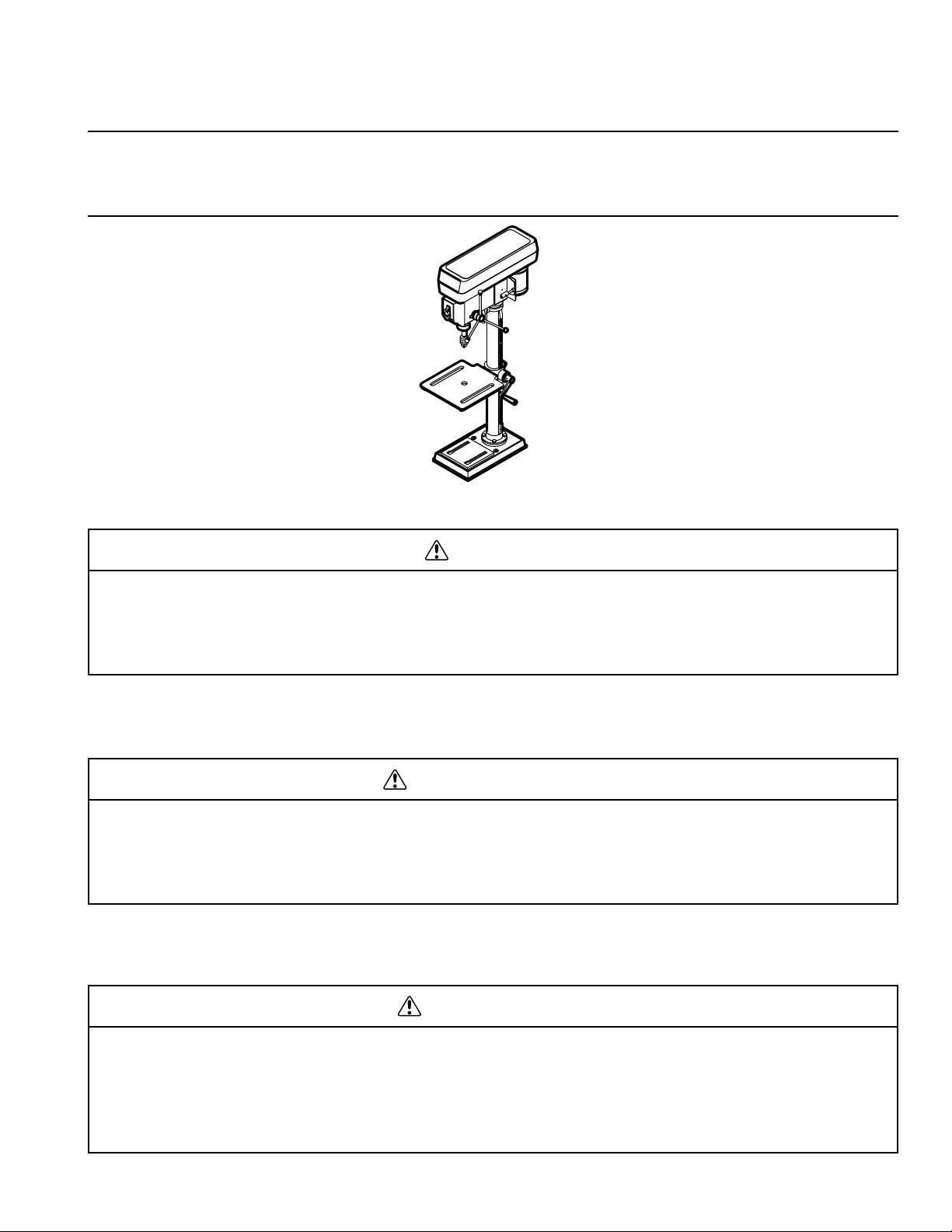
B13F
Bench Drill Press
Perceuse d’établi
Prensa Taladradora de Banco
INSTRUCTION MANUAL AND SAFETY INSTRUCTIONS
WARNING
Improper and unsafe use of this power tool can result in death or serious bodily injury!
This manual contains important information about product safety. Please read and understand
this manual before operating the power tool. Please keep this manual available for others
before they use the power tool.
Hitachi Koki
MANUEL D’INSTRUCTIONS ET CONSIGNES DE SÉCURITÉ
AVERTISSEMENT
L’utilisation inadéquate et non sécuritaire de cet outil électrique peut entraîner la mort ou des
blessures graves! Ce manuel contient des informations importantes sur la sécurité. Veuillez
lire et comprendre ce manuel avant d’utiliser l’outil électrique. Veuillez garder ce manuel
disponible pour les autres utilisateurs, avant qu’ils utilisent cet outil électrique.
MANUAL DE INSTRUCCIONES E INSTRUCCIONES DE SEGURIDAD
ADVERTENCIA
¡El uso inadecuado y no seguro de esta herramienta eléctrica puede ocasionar la muerte o
lesiones corporales graves! Este manual contiene información importante sobre la seguridad
del producto. Por favor lea y entienda este manual antes de usar la herramienta eléctrica.
Por favor mantenga disponible este manual para que otros puedan leerlo antes de usar la
herramienta eléctrica.
Page 2

SECTION Page
Product Specifications..........................................................3
Safety ...................................................................................4
Accessories and Attachments ..............................................7
Carton Contents ...................................................................7
Know Your Drill Press ...........................................................9
Glossary of Terms...............................................................10
SECTION Page
Assembly and Adjustments ................................................11
Operation............................................................................15
Maintenance.......................................................................18
Troubleshooting Guide........................................................19
Parts List.............................................................................55
TABLE OF CONTENTS
HITACHI AUTHORIZED SERVICE CENTERS
Service under this warranty is available from Hitachi Koki U.S.A., Ltd. at:
IN THE U.S.A.
3950 Steve Reynolds Blvd., Norcross, GA 30093
9409 Owensmouth Ave., Chatsworth, CA 91311
OR CALL: (800) 546-1666 for a service center nearest you.
IN CANADA
6395 Kestrel Road, Mississauga, ON L5T 1Z5
OR CALL: (800) 970-2299 for a service center nearest you.
English
SECTION Page
Spécifications du produit ....................................................20
Sécurité ..............................................................................21
Accessoires et équipements...............................................24
Contenu du carton..............................................................24
Connaître sa scie à ruban ..................................................26
Glossaire des termes .........................................................27
SECTION Page
Assemblage et ajustements ...............................................28
Fonctionnement..................................................................32
Entretien .............................................................................35
Guide de dépannage..........................................................36
Liste des pièces..................................................................55
TABLE DES MATIÈRES
CENTRES DE SERVICE AUTORISÉS D’HITACHI
Le service en vertu de cette garantie est disponible de Hitachi Koki U.S.A., Ltd,
aux emplacements suivants :
AUX É-U
3950 Steve Reynolds Blvd., Norcross, GA 30093
9409 Owensmouth Ave., Chatsworth, CA 91311
OU APPELER : (800) 546-1666 pour contacter un centre
de service le plus près de votre domicile.
AU CANADA
6395 Kestrel Road, Mississauga, ON L5T 1Z5
OU APPELER : (800) 970-2299 pour contacter un centre
de service le plus près de votre domicile.
Français
SECCION Página
Especificaciones del producto............................................37
Seguridad ...........................................................................38
Accesorios y aditamentos ..................................................41
Contenido de la caja...........................................................41
Conozca su sierra de banda...............................................43
Glosario de términos ..........................................................44
SECCION Página
Montaje y ajustes................................................................45
Operación...........................................................................49
Mantenimiento....................................................................52
Guía de identificación de problemas ..................................53
Lista de partes....................................................................55
CONTENIDO
CENTROS DE SERVICIO AUTORIZADO DE HITACHI
El servicio de mantenimiento y reparación bajo esta garantía está disponible a través de
Hitachi Koki U.S.A., Ltd. en:
EN EE.UU.
3950 Steve Reynolds Blvd., Norcross, GA 30093
9409 Owensmouth Ave., Chatsworth, CA 91311
O LLAME AL: (800) 546-1666 para averiguar cuál es el
centro de servicio más cercano a usted.
EN CANADA
6395 Kestrel Road, Mississauga, ON L5T 1Z5
O LLAME AL: (800) 970-2299 para averiguar cuál es el
centro de servicio más cercano a usted.
Español
– 2 –
Page 3

PRODUCT SPECIFICATIONS
MOTOR
Power Source...................115 V, 60 HZ, 3.5 AMPS.
Speeds.............................5 - 680~3000 RPM
(Revolutions Per Minute)
Horsepower......................1/3 HP (Continuous Duty)
Capacity
Chuck Size.......................1/2″
Spindle Travel...................2 1/2″
Throat ..............................5″
Table
Size..................................7 13/16″ x 7 13/16″
Tilt ....................................45° Right or Left
Dimensions
Base Size.........................8 1/16″ x 13 3/16″
Height ..............................28″
NET WEIGHT............................61 LB (27.5 kg)
To avoid electrical hazards, fire hazards, or damage to the
tool, use proper circuit protection.
Use a separate electrical circuit for your tools.
Your Drill Press is wired at the factory for 115V operation.
Connect to a 115V, 15 AMP branch circuit and use a 15 Amp
time delay fuse or circuit breaker. To avoid shock or fire,
replace power cord immediately if it is worn, cut or
damaged in any way.
WARNING
Some dust created by power sanding, sawing, grinding, drilling and other construction activities contains chemicals
known to the state of California to cause cancer, birth defects or other reproductive harm. Some examples of these
chemicals are:
• Lead from lead-based paints
• Crystalline silica from bricks, cement and other masonry products
• Arsenic and chromium from chemically treated lumber
Your risk from these exposures varies, depending on how often you do this type of work. To reduce your exposure to
these chemicals, work in a well-ventilated area and work with approved safety equipment such as dust masks that are
specially designed to filter out microscopic particles.
WARNING
SAVE THESE INSTRUCTIONS
– 3 –
English
Page 4

SAFETY
– 4 –
English
GENERAL SAFETY INSTRUCTIONS
BEFORE USING THE DRILL PRESS
Safety is a combination of common sense, staying alert and
knowing how to use this Drill Press.
To avoid mistakes that could cause serious injury, do not plug
the Drill Press in until you have read and understood the
following:
1. READ and become familiar with the entire Operator’s
Manual. LEARN the tool’s application, limitations and
possible hazards.
2. KEEP GUARDS IN PLACE and in working order.
3. REMOVE ADJUSTING KEYS AND WRENCHES.
Form a habit of checking to see that keys and adjusting
wrenches are removed from the tool before turning ON.
4. KEEP WORK AREA CLEAN. Cluttered areas and
benches invite accidents.
5. DON’T USE IN DANGEROUS ENVIRONMENT. Don’t
use power tools in damp or wet locations, or expose
them to rain. Keep work area well lighted.
6. KEEP CHILDREN AWAY. All visitors should be kept
at a safe distance from work area.
7. MAKE WORKSHOP CHILDPROOF with padlocks,
master switches, or by removing starter keys.
8. DON’T FORCE THE TOOL. It will do the job better and
safer at the rate for which it was designed.
9. USE THE RIGHT TOOL. Do not force tool or attachment
to do a job for which it was not designed.
10. USE PROPER EXTENSION CORD. Make sure your
extension cord is in good condition. When using an
extension cord, be sure to use one heavy enough to
carry the current your product will draw. An undersized
cord will result in a drop in line voltage and in loss of
power that will cause the tool to overheat. The table on
page 6 shows the correct size to use depending on cord
length and nameplate ampere rating. If in doubt, use the
next heavier gauge. The smaller the gauge number, the
heavier the cord.
11. WEAR PROPER APPAREL. Do not wear loose clothing,
gloves, neckties, rings, bracelets, or other jewelry that
may get caught in moving parts. Non-slip footwear is
recommended. Wear protective hair covering to contain
long hair.
12. ALWAYS WEAR EYE PROTECTION. Any Drill Press
can throw foreign objects into the eyes that could cause
permanent eye damage. ALWAYS wear Safety Goggles
(not glasses) that comply with ANSI Safety Standard
Z87.1. Everyday eyeglasses have only impact-resistance
lenses. They ARE NOT safety glasses. Safety Goggles
are available at HITACHI.
NOTE: Glasses or goggles not in compliance with
ANSI Z87.1 could cause serious injury.
13. SECURE WORK. Use clamps or a vise to hold work
when practical. It’s safer than using your hand and it
frees both hands to operate tool.
14. DISCONNECT TOOLS before servicing; when changing
accessories such as blades, bits, cutters, and the like.
15. REDUCE THE RISK OF UNINTENTIONAL STARTING.
Make sure switch is in OFF position before plugging in.
16. USE RECOMMENDED ACCESSORIES. Consult the
Operator’s Manual for recommended accessories. The
use of improper accessories may cause serious injury.
17. NEVER STAND ON TOOL. Serious injury could occur if
the tool is tipped or if the cutting tool is unintentionally
contacted.
18. CHECK FOR DAMAGED PARTS. Before further use of
the tool, a guard or other part that is damaged should
be carefully checked to determine that it will operate
properly and perform its intended function – check for
alignment of moving parts, binding of moving parts,
breakage of parts, mounting, and any other conditions
that may affect its operation. A guard or other part that
is damaged should be properly repaired or replaced.
19. NEVER LEAVE TOOL RUNNING UNATTENDED. TURN
POWER “OFF”. Don’t leave tool until it comes to a
complete stop.
20. DON’T OVERREACH. Keep proper footing and balance
at all times.
21. MAINTAIN TOOLS WITH CARE. Keep tools sharp and
clean for best and safest performance. Follow instructions
for lubricating and changing accessories.
22. DO NOT use power tools in the presence of flammable
liquids or gases.
23. DO NOT OPERATE the tool if you are under the
influence of any drugs, alcohol or medication that could
affect your ability to use the tool properly.
24.
ALWAYS operate the Drill Press in a well-ventilated area
and provide for proper dust removal. Use dust collection
systems whenever possible. Dust generated from certain
materials can be hazardous to your health.
WARNING
Page 5

– 5 –
English
SPECIFIC SAFETY INSTRUCTIONS FOR
THE DRILL PRESS
For your own safety, do not try to use your drill press or plug
it in until it is completely assembled and installed according to
the instrucitons, and until you have read and understood this
intstruction manual.
1. THIS DRILL PRESS is intended for use in dry
conditions, indoor use only.
2. WEAR EYE PROTECTION. USE a face or dust mask
along with safety goggles if drilling operation is dusty.
USE ear protectors, especially during extended periods
of operation.
3. DO NOT wear gloves, neckties, or loose clothing.
4. DO NOT try to drill material too small to be securely held.
5. ALWAYS keep hands out of the path of a drill bit. Avoid
awkward hand positions where a sudden slip could
cause your hand to move into the drill bit.
6. DO NOT install or use any drill bit that exceeds 175mm
(7″) in length or extends 150mm (6″) below the chuck
jaws. They can suddenly bend outward or break.
7. DO NOT USE wire wheels, router bits, shaper cutters,
circle (fly) cutters, or rotary planers on this drill press.
8. WHEN cutting a large piece of material, make sure it is
fully supported at the table height.
9. DO NOT perform any operation freehand. ALWAYS hold
the workpiece firmly against the table so it will not rock or
twist. Use clamps or a vise for unstable workpieces.
10. MAKE SURE there are no nails or foreign objects in the
part of the workpiece to be drilled.
11. CLAMP THE WORKPIECE OR BRACE IT against the
left side of the column to prevent rotation. If it is too short
or the table is tilted, clamp it solidly to the table and use
the fence provided.
12. IF THE WORKPIECE overhangs the table such that it will
fall or tip if not held, clamp it to the table or provide
auxiliary support.
13. SECURE THE WORK. Use clamps or a vise to hold the
work when practical. It’s safer than using your hand and it
frees both hands to operate tool.
14. MAKE SURE all clamps and locks are firmly tightened
before drilling.
15. SECURELY LOCK THE HEAD and table support to the
column, and the table to the table support before
operating the drill press.
16. NEVER turn your drill press ON before clearing the table
of all objects (tools, scraps of wood, etc.).
17. BEFORE STARTING the operation, jog the motor switch
to make sure the frill bit does not wobble or vibrate.
18. LET THE SPINDLE REACH FULL SPEED before
starting to drill. If your drill press makes an unfamiliar
noise or if it vibrates excessively, stop immediately, turn
the drill press OFF and unplug. Do not restart the unit
until the problem is corrected.
19. DO NOT perform layout assembly or set up work on the
table while the drill press is in operation.
20. USE THE RECOMMENDED SPEED for any drill press
accessory and for different workpiece material. READ
THE INSTRUCTIONS that come with the accessory.
21. WHEN DRILLING large diameter holes, clamp the
workpiece firmly to the table. Otherwise, the bit may grab
and spin the workpiece at high speeds. DO NOT USE fly
cutters or multiple-part hold cutters, as they can come
apart or become unbalanced in use.
22. MAKE SURE the spindle has come to a complete stop
before touching the workpiece.
23. TO AVOID INJURY from accidental starting, always turn
the switch OFF and unplug the drill press before
installing or removing any accessory or attachment or
making any adjustment.
24. KEEP GUARDS IN PLACE and in working order.
25.
USE ONLY THE SELF-EJECTING TYPE CHUCK KEY
as provided with the drill press.
26. AVOID DIRECT EYE EXPOSURE when using the laser
guide.
27. ALWAYS ENSURE THE LASER BEAM IS AIMED AT A
SURFACE WITHOUT REFLECTIVE PROPERTIES.
Shiny reflective materials are not suitable for laser use.
WARNING
Page 6
ELECTRICAL REQUIREMENTS
POWER SUPPLY AND MOTOR SPECIFICATIONS
To avoid electrical hazards, fire hazards, or damage to the
tool, use proper circuit protection. Use a separate electrical
circuit for your tools. Your drill press is wired at the factory for
115V operation. Connect to a 115V, 15 Amp circuit and use a
15 Amp time delay fuse or circuit breaker. To avoid shock or
fire, if power cord is worn or cut, or damaged in any way,
have it replaced immediately.
GROUNDING INSTRUCTIONS
This tool must be grounded while in use to protect the
operator from electrical shock.
IN THE EVENT OF A MALFUNCTION OR BREAKDOWN,
grounding provides a path of least resistance for electric
current and reduces the risk of electric shock. This tool is
equipped with an electric cord that has an equipment-grounding
conductor and a grounding plug. The plug MUST be plugged
into a matching receptacle that is properly installed and
grounded in accordance with ALL local codes and ordinances.
DO NOT MODIFY THE PLUG PROVIDED. If it will not fit the
receptacle, have the proper receptacle installed by a qualified
electrician.
IMPROPER CONNECTION of the equipment-grounding
conductor can result in risk of electric shock. The conductor
with green insulation (with or without yellow stripes) is the
equipment-grounding conductor. If repair or replacement of
the electric cord or plug is necessary, DO NOT connect the
equipment-grounding conductor to a live terminal.
CHECK with a qualified electrician or service person if you
do not completely understand the grounding instructions,
or if you are not sure the tool is properly grounded.
USE ONLY 3-wire extension cords that have 3-prong
grounding plugs and 3-pole receptacles that accept the
tool’s plug. Repair or replace damaged or worn cord
immediately.
Use a separate electrical circuit for your tools. This circuit
must not be less than #12 wire and should be protected with
a 15 Amp time delay fuse. Before connecting the motor to the
power line, make sure the switch is in the OFF position and
the electric current is rated the same as the current stamped
on the motor nameplate. Running at a lower voltage will
damage the motor.
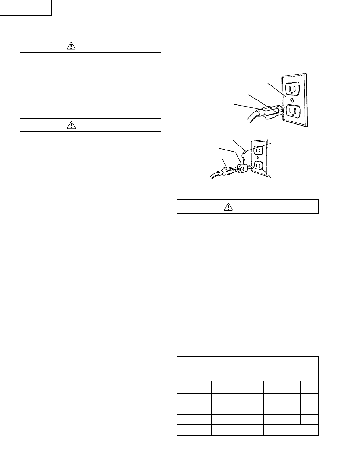
This tool is intended for use on a circuit that has a receptacle
like the one illustrated in Figure A showing a 3-prong
electrical plug and receptacle that has a grounding conductor.
If a properly grounded receptacle is not available, an adapter
(Figure B) can be used to temporarily connect this plug to
a 2-contact ungrounded receptacle. The adapter (Figure B)
has a rigid lug extending from it that MUST be connected
to a permanent earth ground, such as a properly grounded
receptacle box. THE TEMPORARY ADAPTER SHOULD
BE USED ONLY UNTIL A QUALIFIED ELECTRICIAN CAN
INSTALL A PROPERLY GROUNDED OUTLET. The
Canadian Electrical Code prohibits the use of adapters.
CAUTION: In all cases, make certain the receptacle is
properly grounded. If you are not sure, have a qualified
electrician check the receptacle.
This Drill Press is for indoor use only. Do not expose to rain
or use in damp locations.
GUIDELINES FOR EXTENSION CORDS
USE PROPER EXTENSION CORD. Make sure your extension
cord is in good condition. When using an extension cord,
be sure to use one heavy enough to carry the current your
product will draw. An undersized cord will cause a drop in line
voltage, resulting in loss of power and cause overheating.
The table below shows the correct size to use depending on
cord length and nameplate ampere rating. If in doubt, use
the next heavier gauge. The smaller the gauge number
the heavier the cord.
Be sure your extension cord is properly wired and in good
condition. Always replace a damaged extension cord or have
it repaired by a qualified person before using it. Protect your
extension cords from sharp objects, excessive heat and
damp or wet areas.
MINIMUM GAUGE FOR EXTENSION CORDS (AWG)
(When using 120 Volt only)
Ampere Rating Total length in feet
More Than
Not
More Than
25′ 50′ 100′ 150′
0 6 18 16 16 14
6 10 18 16 14 12
10 12 16 16 14 12
12 16 14 12 Not Applicable
WARNING
WARNING
WARNING
Properly Grounded
3-Prong Receptacle
Grounding Prong
3-Prong Plug
Grounding Lug
Adapter
3-Prong Plug
Make Sure This
is Connected to
a Known Ground
2-Prong Receptacle
Fig. A
Fig. B
– 6 –
English
Page 7

ACCESSORIES AND ATTACHMENTS
RECOMMENDED ACCESSORIES
To avoid injury:
• Use only accessories recommended for this Drill Press.
• Follow instructions that accompany accessories. Use of
improper accessories may cause hazards.
• Use only accessories designed for this Drill Press to
avoid injury from thrown broken parts or workpieces.
• Do not use any accessory unless you have completely
read the instruction or operator’s manual for that
accessory.
WARNING
CARTON CONTENTS
– 7 –
English
UNPACKING AND CHECKING CONTENTS
Carefully unpack the Drill Press and all its parts, and compare
against the illustration following. Place the saw on a secure
surface and examine it carefully.
• To avoid injury from unexpected starting, do not plug
the power cord into a power source receptacle during
unpacking and assembly. This cord must remain
unplugged whenever you are assembling or adjusting
the drill press.
• If any part is missing or damaged, do not plug the drill
press in until the missing or damaged part is replaced,
and assembly is complete.
• To protect the drill press from moisture, a protective
coating has been applied to the machined surfaces.
Remove this coating with a soft cloth moistened with
kerosene or WD-40.
To avoid fire or toxic reaction, never use gasoline, naphtha,
acetone, lacquer thinner or similar highly volatile solvents to
clean the drill press.
TABLE OF LOOSE PARTS
ITEM DESCRIPTION QUANTITY
DRILL PRESS:
A. Head Assembly 1
B. Table 1
C. Base 1
D. Column Assembly 1
E. Feed Handle 3
F. Crank Handle 1
G. Batteries 2
LOOSE PARTS BAG:
H. Hex Bolts 4
I. Hex Wrench 1
J. Flat Washers 4
BOX:
K. Chuck Key 1
L. Chuck 1
WARNING
WARNING
Page 8
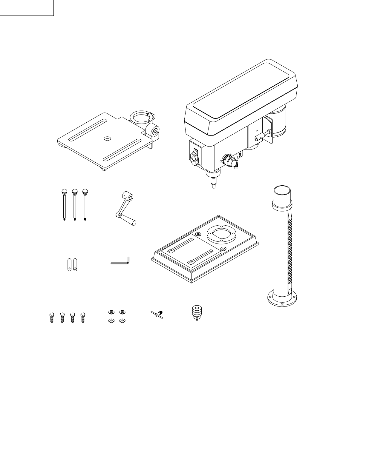
UNPACKING YOUR DRILL PRESS
B
A
C
D
E
F
G
I
H
J
K
L
– 8 –
English
Page 9
KNOW YOUR DRILL PRESS
Belt Guard Cover
Cover Knob
Table Support
Lock
Motor
Belt Pulleys
Spindle
Quill
Chuck
Chuck Key
Spring Cover
Feed Spring
Table Assembly
Belt Tension
Lock Knob
Head Locking
Set Screw
ON/OFF Switch
Chuck
Column Collar
Laser Guide
Feed Handles
Rack
Table Support
Table Crank
Column Support
Base
Bevel Scale
Table Bevel Lock
– 9 –
English
Page 10

GLOSSARY OF TERMS
– 10 –
English
DRILL PRESS TERMS
BASE GUIDES – Supports drill press. For additional stability,
holes are provided in base to bolt drill press to bench.
BACKUP MATERIAL – A piece of scrap wood placed
between the workpiece and table. The backup board prevents
wood in the workpiece from splintering when the drill passes
through the backside of the workpiece. It also prevents drilling
into the table top.
BELT GUARD ASSEMBLY – Covers the pulleys and belt
during operation of the drill press.
BELT TENSION – Refer to the Assembly Section, “Installing
and Tensioning Belt”.
BELT TENSION LOCK KNOBS – Tightening the knobs locks
the motor bracket support and the belt tension handle,
maintaining correct belt distance and tension.
BEVEL SCALE – Shows degree of table tilt for bevel
operations. The scale is mounted on the side of the table
bracket.
CHUCK – Holds a drill bit or other recommended accessory
to perform desired operations.
CHUCK KEY – A self-ejecting chuck key which will pop out
of the chuck when you let go of it. This action is designed to
help prevent throwing of the chuck key from the chuck when
the power is turned ON. Do not use any other key as a
substitute; order a new one if Damaged or Lost.
COLUMN – Connects the head, table, and base on a one
piece tube for easy alignment and movement.
COLUMN COLLAR – Holds the rack to the column. The rack
remains movable in the collar to permit table support
movements.
COLUMN SUPPORT – Supports the column, guides the rack
and provides mounting holes for the column to the base.
DEPTH SCALE STOP NUTS – Lock the spindle to a
selected depth.
DEPTH SCALE – Indicates depth of hole being drilled.
DRILL BIT – The cutting tool used in the drill press to make
holes in a workpiece.
DRILL ON/OFF SWITCH – Has a locking feature. This
feature is intended to help prevent unauthorized and possible
hazardous use by children and others. Insert the key into the
switch to turn the drill press on.
DRILLING SPEED – Changed by placing the belt in any of
the steps (grooves) in the pulleys. See the Spindle Speed
Chart inside belt guard or in the manual.
FEED HANDLE – Moves the chuck up or down. If necessary,
one or two of the handles may be removed whenever the
workpiece is of such unusual shape that it interferes with the
handles.
RACK – Combines with gear mechanism to provide easy
elevation of the table by the hand operated table crank.
RPM – Revolutions per minute. The number of turns
completed by a spinning object in one minute.
SPINDLE SPEED – The RPM of the spindle.
SPRING CAP – Adjusts the quill return spring tension.
TABLE SUPPORT LOCK – Tightening locks the table
support tot he column. Always have it locked in place while
operating the drill press.
TABLE – Provides a working surface to support the
workpiece.
TABLE ARM – Extends beyond the table support for
mounting and aligning the table.
TABLE BEVEL LOCK – Locks the table in any position from
0° to 45°.
TABLE CRANK – Elevates and lowers the table. Turn
clockwise to elevate the table. Support lock must be released
before operating the crank.
TABLE LOCK – Locks the table after it is rotated to various
positions.
TABLE SUPPORT – Rides on the column to support the
table arm and table.
WORKPIECE – Material being drilled.
Page 11
ESTIMATED ASSEMBLY TIME 20-40 MINUTES
ASSEMBLY INSTRUCTIONS
For your safety, never connect plug to power source
receptacle until all assembly and adjustment steps are
completed, and you have read and understood the safety
and operating instructions.
TOOLS NEEDED
The Drill Press is very heavy and MUST be assembled with
the help of 2 PEOPLE OR MORE, to safely assemble it.
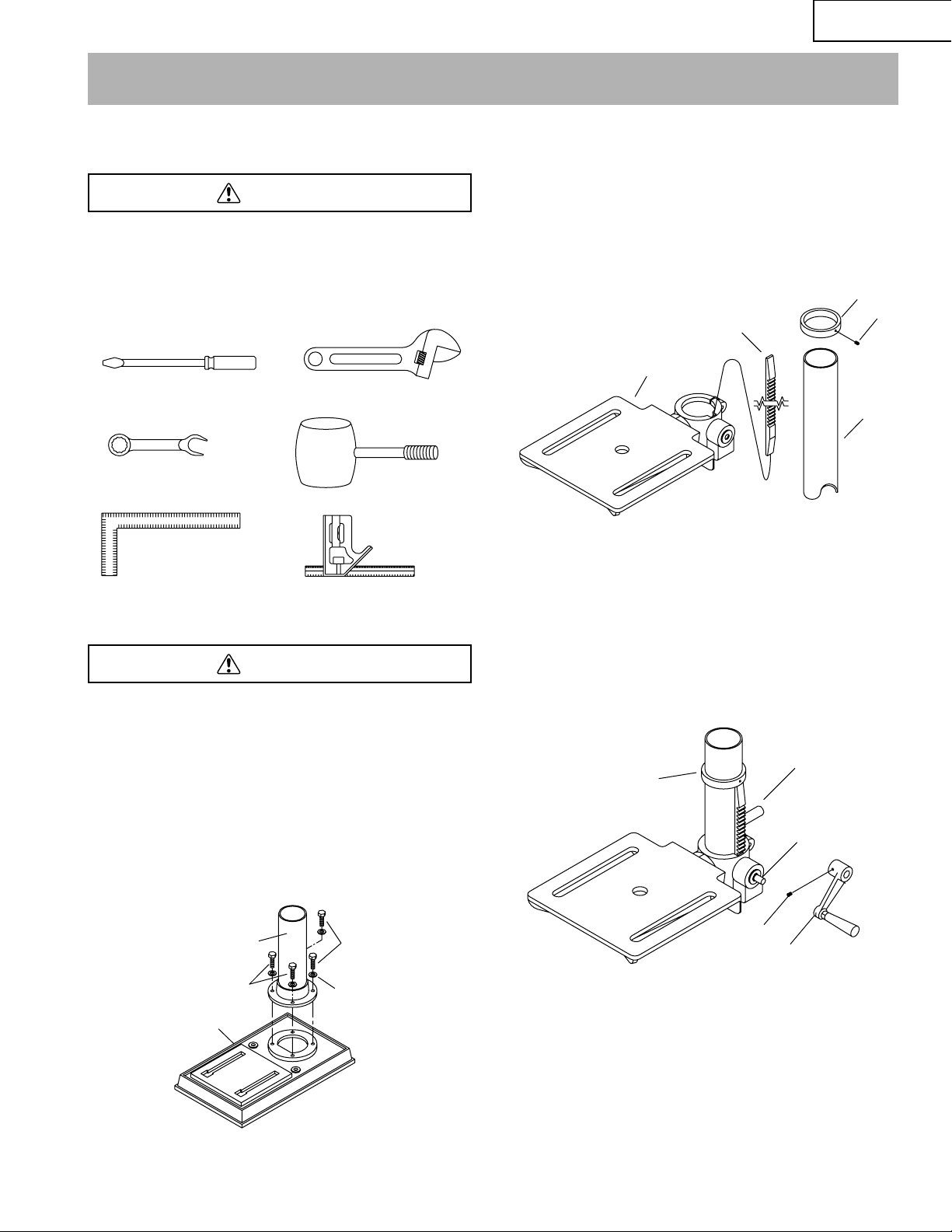
COLUMN SUPPORT TO BASE (Fig. A)
1. Position the base (1) on floor or bench.
2. Place the column (2) on the base, aligning the holes in
the column support with the holes in the base.
3. Locate the four long hex bolts (3) and washers (4) from
the loose parts bag.
4. Place a bolt in each hole through the column support and
the base. Tighten with an adjustable wrench.
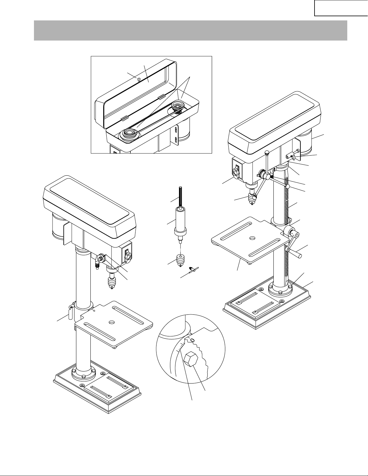
INSTALLING THE TABLE (Fig. B and C)
1. Loosen set screw (1). Remove rack (2) and retaining ring
(3) from column (4).
2. Place rack inside table assembly bracket (5) with large,
unmachined portion of rack to the top. Slide rack into slot
in bracket so that teeth of reack engage pinion gear in
bracket.
3. Slide table assembly with rack over column. Place bottom
end of rack inside beveled edge of column flange.
4. (Fig. C) Slide rack retaining ring (3) over column with
beveled edge down. Position ring against top of rack so
that rack is in beveled edge of ring. Secure ring with set
screw (1).
5. Rotate table assembly around column. Adjust rack
retaining ring as necessary to prevent binding of rack.
6. Attach crank handle (6) to shaft (7), rotate to remove
slack, and shoulder crank handle against table bracket.
Secure handle with screw (8).
7. Tighten table bracket locking handle (9) to secure table
assembly.
WARNING
WARNING
ASSEMBLY AND ADJUSTMENTS
Slotted Screwdriver
Combination Wrench
Framing Square
8″ & 10″ Adjustable Wrench
Combination Square
Mallet
Fig. A
2
3
3
4
1
Fig. B
Fig. C
3
1
4
2
5
6
9
7
3
8
– 11 –
English
Page 12
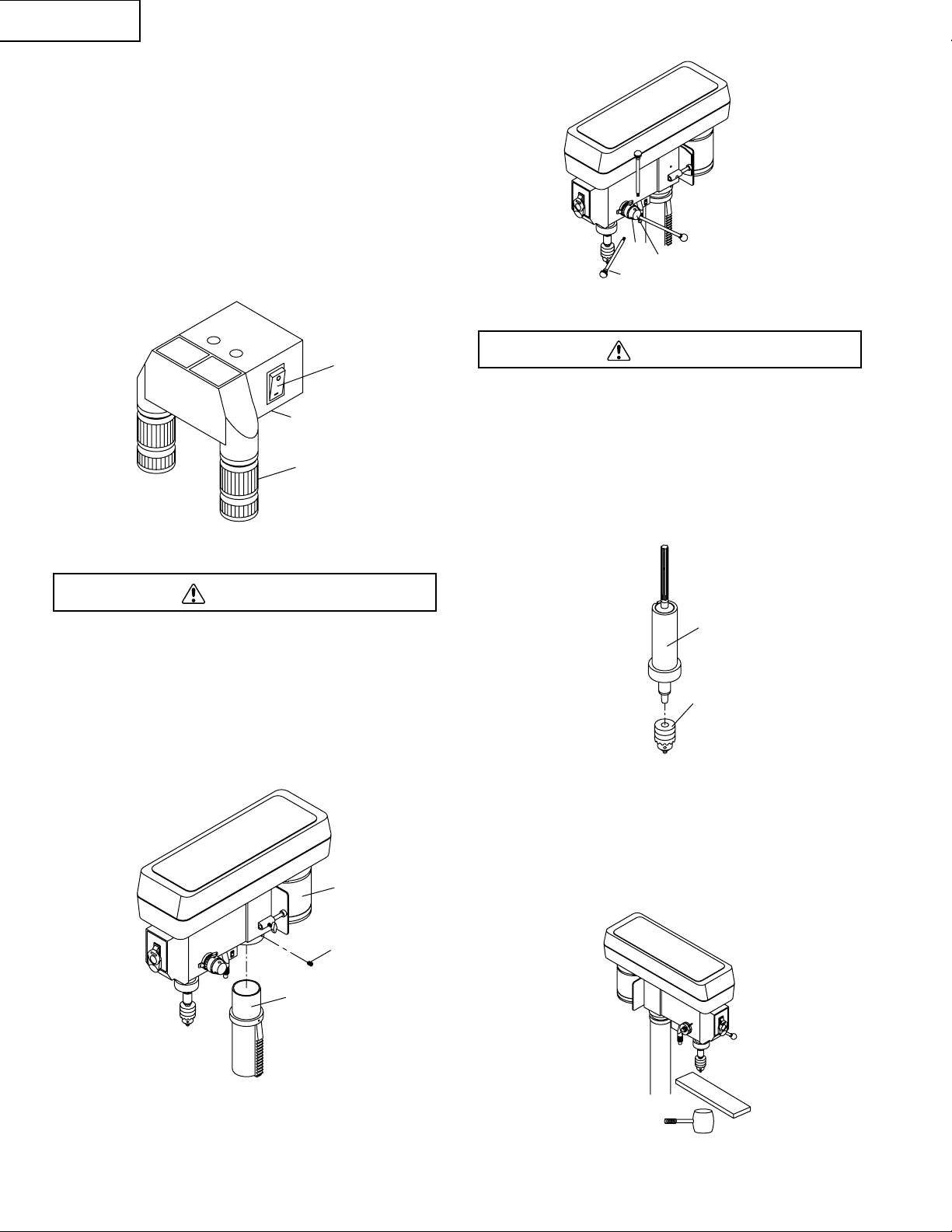
INSTALLING BATTERY FOR LASER GUIDE (Fig. C-1)
1. Open the cover (1) of battery compartment by sliding
cover towards switch.
2. Install 2 pieces of 1.5V batteries into the battery
compartment according to the polarity indicated on
compartment.
3. Close the cover
4. Turn on the switch (3) to check the LASER GUIDE
OPERATION.
NOTE: Replace the batteries with batteries that have a
reating of 1.5 volts (Number 4 sereis and AAA size or
equivalent). When replacing the batteries, the laser guide
should be thoroughly cleansed. Use a soft paintbrush or
similar device, to remove all sawdust and debris.
INSTALLING THE HEAD (Fig. D)
The Drill Press head is very heavy and MUST be lifted witht
he help of 2 PEOPLE OR MORE to safely assemble the Drill
Press head on the column.
1. Carefully lift the head (1) above the column (2) and slide
it onto the column. Make sure the head slides down over
the column as far as possible. Align the head with the
base.
2. Using the hex wrench, tighten the two head lock set
screws (3).
INSTALLING FEED HANDLES (Fig. E)
1. Locate the three feed handles in the loose parts bag.
2. Screw the feed handles (1) into the threaded holes (2) in
the hub (3). Tighten.
INSTALLING THE CHUCK (Fig. F and G)
Before any assembly of the chuck and arbor to the drill press
head, clean all mating surfaces with a non-petroleum based
product; such as alcohol or lacquer thinner. Any oil or grease
used in the packing of these parts must be removed,
otherwise the chuck may come loose during operation.
1. Open the jaws of the chuck (1) by rotating the chuck
sleeve clockwise. To prevent damage, make sure the
jaws are completely receded into the chuck.
2. Push the chuck (1) onto the spindle (2).
NOTE: Clean the spindle taper with a non-alcohol based
cleaner before inserting it into the chuck.
3. Using a rubber mallet, plastic-tipped hammer, or a block
of wood and a hammer, firmly tap the chuck upward into
position on the spindle shaft.
WARNING
WARNING
Fig. E
1
3
2
Fig. F
2
1
Fig. G
Fig. D
1
2
3
Fig. C-1
3
1
2
– 12 –
English
Page 13
DRILL PRESS ADJUSTMENTS
CAUTION: All the adjustments for the operation of the drill
press have been completed at the factory. Due to normal
wear and use, some occasional readjustments may be
necessary.
To prevent personal injury, always disconnect the plug from
the power source when making any adjustment.
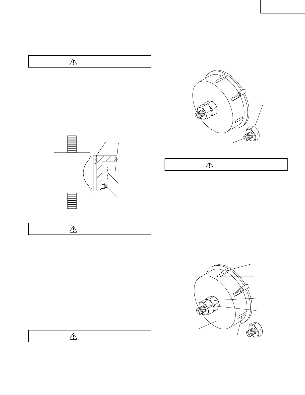
TILTING THE TABLE (Fig. H)
NOTE: The bevel scale has been included to measure
approximate bevel angles. if precision is necessary, a square
or other measuring tool should be used to position the table.
To use the bevel scale (1):
1. Remove pin and nut (2). Tighten nut until pin slips out.
2. Loosen the large hex head bevel locking bolt (3).
To prevent injury, be sure to hold the table assembly, so it will
not swivel or tilt.
3. Tilt the table, aligning the desired angle measurement to
the zero line scribed on the table opposite the bevel
scale (1).
4. Tighten the bevel locking bolt (3).
5. To return the table to its original position, loosen the
bevel locking bolt (3). Realign the bevel scale (1) to the 0
scribed line on the table.
6. Back nut out several turns, reinsert pin and nut into table,
and tap into place with hammer.
7. Tighten the bevel locking bolt.
NOTE: The table has been removed from the illustration for
clarity.
To prevent personal injury, always disconnect the plug from
the power source when making any adjustment.
SPINDLE / QUILL (Fig. I)
Rotate the feed handles counterclockwise to lower spindle to
its lowest position. Hand support the spindle securely and
move it back and forth around the axis. If there is play, do the
following:
1. Loosen the lock nut (1).
2. Turn the screw (2) clockwise to eliminate the play, but
without obstructing the upward movement of the spindle.
3. Tighten the lock nut (1).
To prevent personal injury, always disconnect the plug from
the power source when making any adjustment.
QUILL RETURN SPRING (Fig. J)
The quill return spring may need adjustment if the tension
causes the quill to return too rapidly or too slowly.
1. Lower the table for additional clearance.
2. Place a screwdriver in the lower front notch (1) of the
spring cap (2). Hold it in place while loosening and
removing only the outer jam nut (3).
3. With the screwdriver still engaged in the notch loosen the
inner nut (4) just until the notch (5) disengages from the
boss (6) on the drill press head.
CAUTION: DO NOT REMOVE THIS INNER NUT, because
the spring will forcibly unwind.
4. Carefully turn the spring cap (2) counterclockwise with
the screwdriver, engaging the next notch.
5. Lower the quill to the lowest position by rotating the feed
handle in a counterclockwise direction while holding the
spring cap (2) in position.
WARNING
WARNING
WARNING
WARNING
Fig. H
2
1
3
Fig. I
1
Fig. J
1
2
3
4
5
6
2
– 13 –
English
Page 14
6. If the quill moves up and down as easily as you desire,
tighten the inner nut (4) with the adjustable wrench. If too
loose, repeat steps 2 through 4 to tighten. If too tight,
reverse steps 3 and 4. DO NOT OVERTIGHTEN and
restrict quill movement.
7. Replace the jam nut (3) and tighten against the inner nut
(4) to prevent the inner nut from reversing.
To avoid injury from an accidental start, ALWAYS make sure
the switch is in the OFF position, the switch key is removed,
and the plug is not connected to the power source outlet
before making belt adjustments.
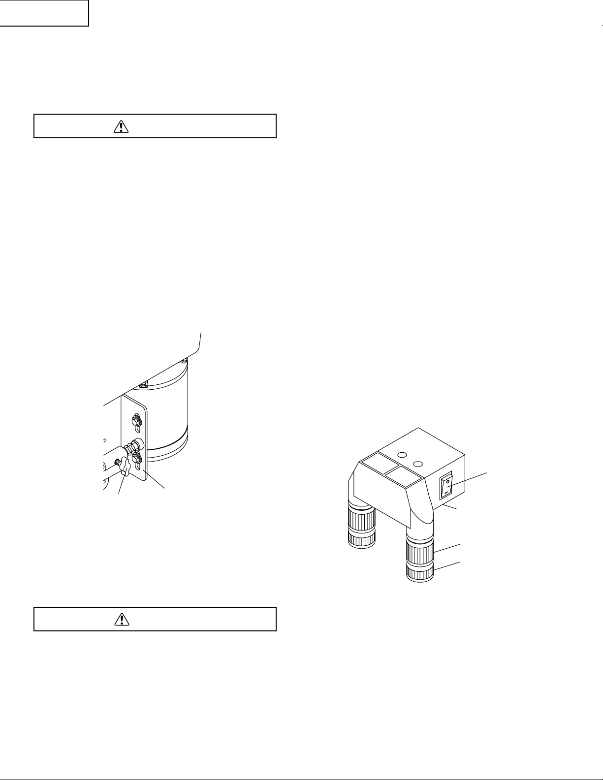
BELT TENSION (Fig. K)
1 To release the belt tension, turn the belt tension lock
knob (1) on the right side of the drill press head
counterclockwise.
2. To tighten the belts, push the motor mounting plate (2)
toward the rear (motor) end.
3. To loosen the belts, pull the motor mounting plate (2)
toward the front (switch) end.
4. Lock the belt tension lock knob (1) by turning clockwise.
NOTE: Belt tension is correct if the belt deflects
approximately 1/2 inch when pressed at its center.
THE LASER GUIDE
Your tool is equipped with our latest innovation, the Laser
Guide, a battery powered device using Class IIIa laser
beams. The laser beams will enable you to preview the drill
bit path on the workpiece to be drilled before you begin your
operation.
AVOID DIRECT EYE CONTACT
A Laser light is radiated when the laser guide is turned on.
Avoid direct eye contact. Always turn off the laser and unplug
the drill press from the power source before making any
adjustments.
• A laser pointer is not a toy and should not come into
hands of children. Misuse of this appliance can lead to
irreparable eye injuries.
• Any adjustments to increase the laser power is forbidden.
• When using the laser pointer, do not point the laser beam
towards people and / or reflecting surfaces. Even a laser
beam of lower intensity may cause eye damage.
Therefore, do not look directly into the laser beam.
• If the laser pointer is stored for more than three months
without use, please remove the batteries to avoid
damage from possibly leaking batteries.
• The laser pointer includes no user serviceable
components. Never open the housing for repair or
adjustments.
• On units equipped with the Laser-Guide attachment,
repairs shall only be carried out by the laser
manufacturer or authorized agent.
• Laser Warning label: Max output <5mW DIODE LASER:
630-660nm, Complies with 21CFR 1040.10 and 1040. 11.
ADUSTING THE LASER LINES (Fig. L)
How to check and adjust the Laser Beam Alignment:
Check the laser beam alignment to ensure the intersection of
the laser lines precisely at the spot where the drill bit meets
the workpiece. If it is not, the laser lines should be adjusted
using the laser adjustment knobs located on the opposite
sides of the head assembly.
1. Mark an “X” on a piece of scrap wood.
2. Insert a small drill bit into the chuck and align its tip to
the intersection of the lines of the “X”.
3. Secure the board to the table.
4. Turn on the laser (3) and verify the laser lines align with
the “X” on the workpiece.
5. If the laser lines do not align, loosen knobs (2) on each
side of the laser module and rotate the lasers (4) until the
lines meet in the center of the “X”. Retighten the knobs to
secure.
DANGER
WARNING
Fig. K
1
Fig. L
3
4
2
1
2
– 14 –
English
Page 15
BASIC DRILL PRESS OPERATIONS
SPEEDS AND BELT PLACEMENT (Fig. M)
This drill press has 5 speeds, as listed below:
680 RPM; 1160 RPM; 1780 RPM;
2380 RPM; 3000 RPM
See the inside of the pulley guard for same chart as shown
in Figure M.
To avoid possible injury, keep the guard closed, in place, and
in proper working order while the tool is in operation.
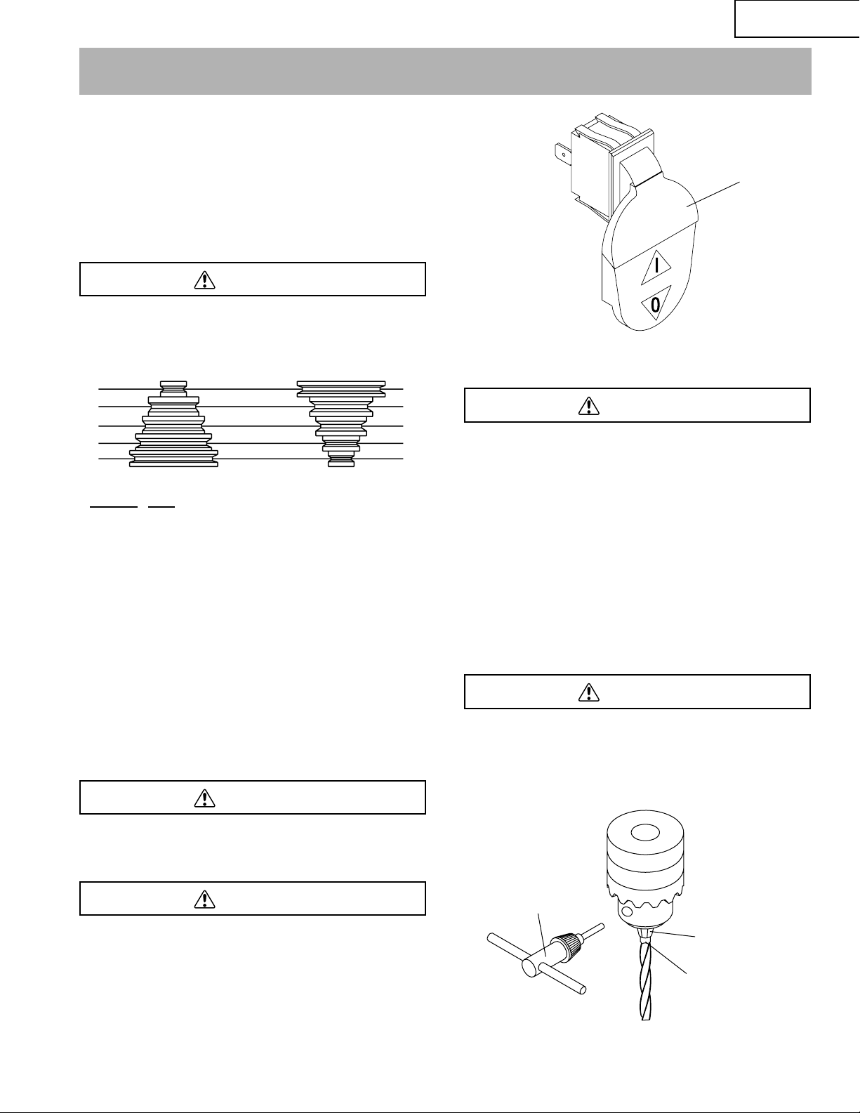
ON/OFF SWITCH (Fig. N)
The keyed switch is intended to prevent unauthorized use of
the drill press.
1. To turn the drill press ON (I) insert the yellow key (1) into
the key slot in the center of the switch.
2. Push the key firmly into the slot, then push switch to the
ON position to start the drill press.
3. To turn the drill press OFF (O) push the switch to the
down position.
4. Remove the yellow switch key, when the drill press has
come to a complete stop, by gently pulling it outward.
Remove the switch key whenever the drill press is not in use.
Place it in a safe place and out of reach of children.
ALWAYS lock the switch OFF when the drill press is not in
use. Remove the key and keep it in a safe place. In the event
of power failure, blown fuse, or tripped circuit breaker, turn
the switch OFF and remove the key, preventing an accidental
startup when power comes on.
LASER ON / OFF SWITCH (Fig. L)
To turn the laser ON or OFF, press the rocker switch (3)
Laser is radiated when laser guide is turned on. Avoid direct
eye exposure. Always un-plug drill press from power source
before making any adjustment.
INSTALLING A DRILL BIT IN THE CHUCK (Fig. O)
1 With the switch “OFF” and the yellow switch key
removed, open the chuck jaws (1) using the chuck key
(2). Turn the chuck key counterclockwise to open the
chuck jaws (1).
2. Insert the drill bit (3) into the chuck far enough to obtain
maximum gripping by the jaws, but not far enough to
touch the spiral grooves (flutes) of the drill bit when the
jaws are tightened.
3. Make sure that the drill is centered in the chuck.
4. Turn the chuck key clockwise to tighten the jaws.
To avoid injury or accident by the chuck key ejecting forcibly
from the chuck when the power is turned ON, use only the
self-ejecting chuck key supplied with this drill press. ALWAYS
recheck and remove the chuck key before turning the power
ON.
WARNING
WARNING
DANGER
WARNING
WARNING
OPERATION
Fig. M - SPEED CHART
Fig. N
Fig. O
1
1
2
3
– 15 –
English
Spindle Motor
5
4
3
2
1
Belt
Location
5-5
4-4
3-3
2-2
1-1
RPM
3000
2380
1780
1160
680
5
4
3
2
1
Page 16
English
– 16 –
To prevent the workpiece or backup material from being torn
from your hands while drilling, you MUST position the
workpiece against the LEFT side of the column. If the
workpiece or backup material is not long enough to reach the
column, clamp them to the table. Failure to secure the
workpiece could result in personal injury.
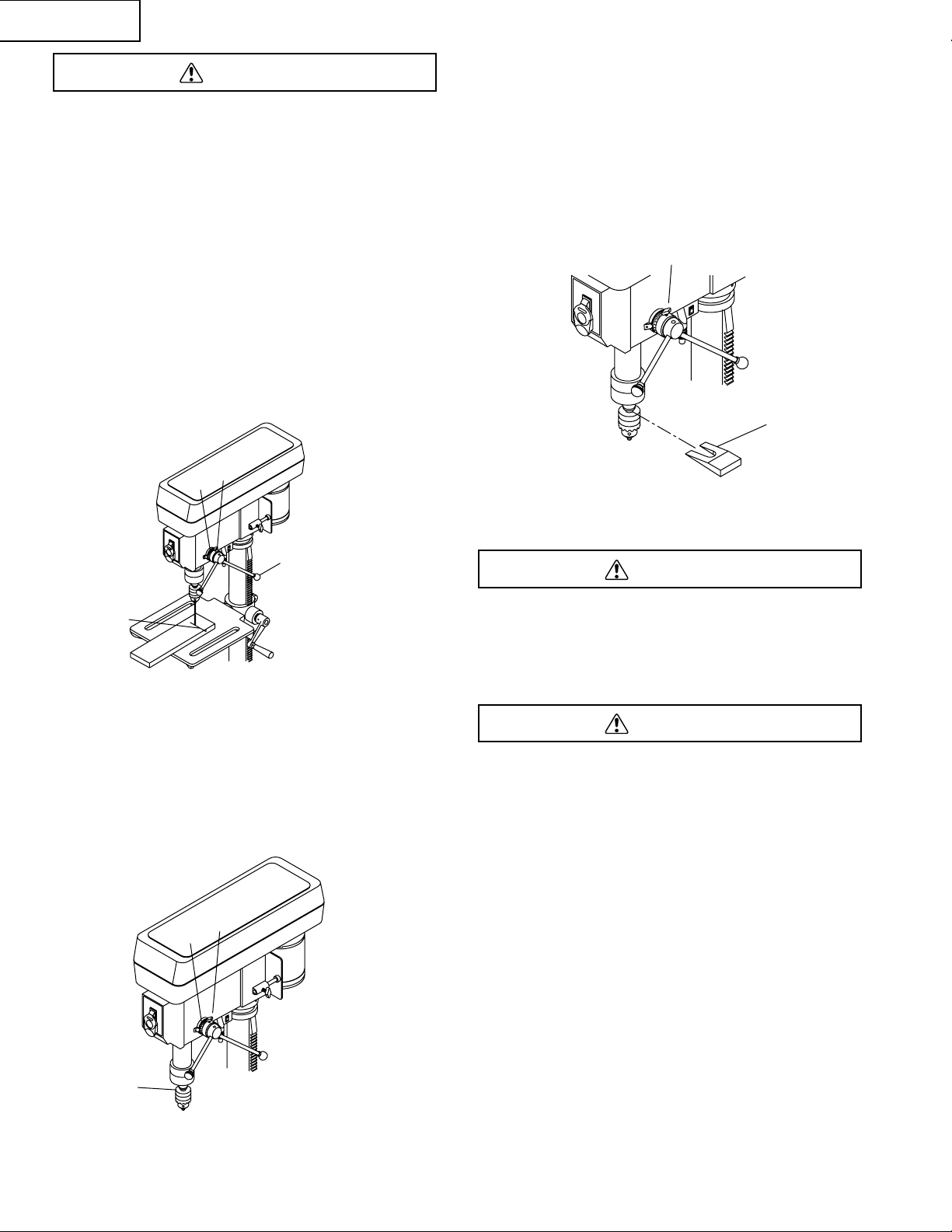
DRILLING TO A SPECIFIC DEPTH (Fig. P)
1. Mark the depth (1) of the hole on the side of the
workpiece.
2. With the switch OFF, bring the drill bit down until the tip is
even with the mark.
3. Hold the feed handle (2) at this position.
4. Turn the depth scale ring (3) clockwise, until it is against
the depth stop.
5. Lock scale ring in place with depth knob (4).
6. The drill bit will stop after traveling the distance selected
on the depth scale.
LOCKING THE CHUCK AT THE DESIRED DEPTH (Fig. Q)
1. With the switch OFF, turn the feed handles until the
chuck (1) is at the desired depth. Hold the feed handles
at this position.
2. Turn the depth scale ring (3), clockwise, until it is against
the depth stop.
3. Lock scale ring in place with depth knob (2).
4. The chuck will now be held at this position when the feed
handles are released.
REMOVING CHUCK AND ARBOR (Fig. R)
1. With the switch OFF and the unit unplugged, adjust the
depth stop screw (10 to hold the drill at a depth of three
inches. (See instructions for “LOCKING CHUCK AT
DESIRED DEPTH“).
2. Insert a wedge (2) between chuck and quill.
3. Tap wedge (2) lightly with a plastic tipped hammer, until
the chuck falls away from the spindle.
NOTE: Place one hand below the chuck to catch it when it
falls out.
BASIC OPERATION ISTRUCTIONS
To get the best results and minimize the likelihood of personal
injury, follow these instructions for operating your drill press.
For your own safety, always observe the SAFETY
INSTRUCTIONS listed here and on pages 3, 4 & 5 of the
instruction manual.
YOUR PROTECTION
To avoid being pulled into the power tool, do not wear loose
clothing, gloves, neckties or jewelry. Always tie back long hair.
1. If any part of your drill press is missing, malfunctioning,
damaged or broken, stop operation immediately until that
part is properly repaired or replaced.
2. Never place your fingers in a position where they could
contact the drill bit or other cutting tool. The workpiece
may unexpectedly shift, or your hand could slip.
3. To avoid injury from parts thrown by the spring, follow
instructions exactly when adjusting the spring tension of
the quill.
4. To prevent the workpiece from being torn from your
hands, thrown, spun by the tool, or shattered, always
properly support your workpiece as follows:
a. Always position BACKUP MATERIAL (used beneath
workpiece) so that it contacts the left side of the
column, or use the fence provided and a clamp to
brace a small workpiece.
b. Whenever possible, position the WORKPIECE to
contact the left side of the column. If it is too short or
the table is tilted, use the fence provided or clamp it
solidly to the table, using the table slots.
c. When using a drill press vise, always fasten it to the
table.
WARNING
WARNING
WARNING
Fig. P
3
4
1
2
Fig. Q
3
1
2
Fig. R
1
2
Page 17
d. Never do any work freehand (hand-holding the
workpiece rather than supporting it on the table),
except when polishing.
e. Securely lock the head and support to the column, the
table arm to the support, and the table to the table
arm, before operating the drill press.
f. Never move the head or table while the tool is running.
g. Before starting an operation, jog the motor switch to
make sure the drill or other cutting tool does not
wobble or cause vibration.
h. If a workpiece overhangs the table so it will fall or tip if
not held, clamp it to the table or provide auxiliary
support.
i. Use fixtures for unusual operations to adequately hold,
guide, and position workpieces.
j. Use the SPINDLE SPEED recommended for the
specific operation and workpiece material. Check the
panel on the inside pulley cover or the chart below for
drilling speed information. For accessories, refer to the
instructions provided with each accessory.
5. Never climb on the drill press table, it could break or pull
the entire drill press down on you.
6. Turn the motor switch “OFF”, and put away the switch key
when leaving the drill press.
7. To avoid injury from thrown work or tool contact, do not
perform layout, assembly, or set up work on the table
while the cutting tool is rotating.
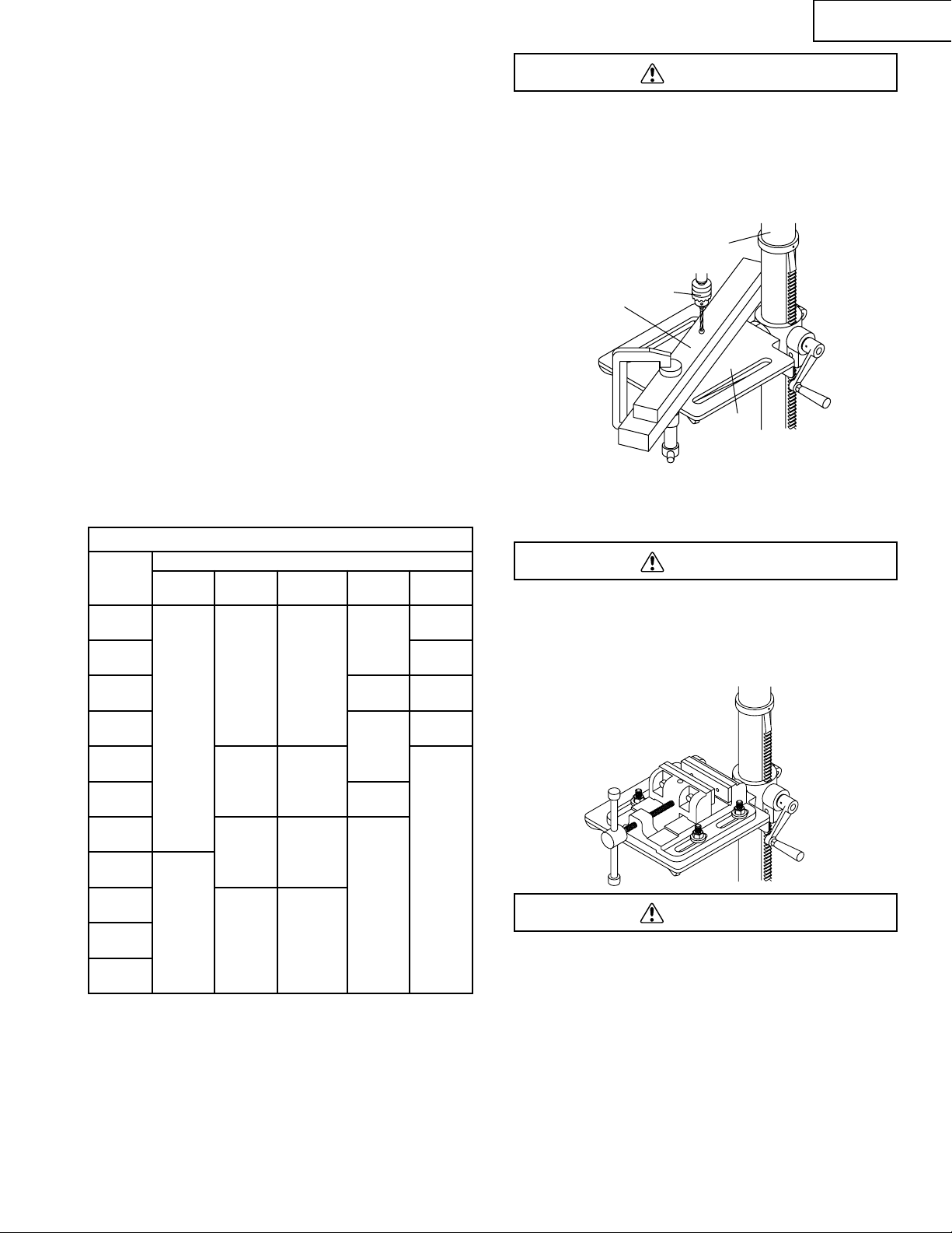
POSITIONING THE TABLE AND WORKPIECE (Fig. S and T)
1. Lock the table (1) to the column (2) at a position so the
tip of the drill bit (3) is just above the top of the workpiece
(4).
2. ALWAYS place BACK-UP MATERIAL (scrap wood) on
the table beneath the workpiece. This will prevent
splintering or heavy burring on the underside of the
workpiece. To keep the back-up material from spinning
out of control, it MUST contact the LEFT side of the
column.
To prevent the workpiece or back-up material from being torn
from your hands while drilling, you MUST position it against
the LEFT side of the column. If the workpiece or the back-up
material is not long enough to reach the column, use the
fence provided with the drill press to brace the workpiece.
Failure to do this could result in personal injury.
3. For small pieces that cannot be clamped to the table, use
a drill press vise (optional accessory)
The drill press vise MUST be clamped or bolted to the table
to avoid injury from a spinning workpiece, or damaged vise or
bit parts.
Remove the drill press fence when it interferes with other drill
press accessories.
To avoid injury from spinning work or tool breakage, always
clamp workpiece and back-up material securely to the table
before operating the drill press with the table tilted.
FEEDING
1. Pull down the feed handles with only enough effort to
allow the drill bit to cut.
2. Feeding too slowly might cause the drill bit to burn.
Feeding too rapidly might stop the motor, cause the belt
or drill to slip, or tear the workpiece loose and break the
drill bit.
3. When drilling metal, it may be necessary to lubricate the
drill bit tip with motor oil, to prevent burning.
WARNING
WARNING
WARNING
English
– 17 –
Fig. S
1
3
4
2
Fig. T
DRILLING SPEED TABLE (RPM )
Drill Bit
Diam.
(Inches)
Material
Wood
Aluminum
Plastic
Mild
Steel
Stainless
1/32
3000 3000 3000 3000 3000
1/16
1780
2380
1/8
1780
2380
1160
1160
3/16
1160
1160
680
680
1/4
1780
2380
1780
2380
5/16
680
680
3/8
1160
1160
1160
1160
7/16
1780
2380
1/2
680
680
680
680
9/16
5/8
Page 18

English
– 18 –
MAINTAINING YOUR DRILL PRESS
For our own safety, turn the switch OFF and remove the plug
from the power source outlet before maintaining or lubricating
your drill press.
Frequently blow out, using an air compressor or dust vacuum,
any dust that accumulates inside the motor. A coat of paste
wax applied to the table and column will help to keep the
surface clean & help avoid rust.
To avoid shock or fire hazard, if the power cord is worn
or cut on any way, have it replaced immediately.
LUBRICATION
All of the drill press ball bearings are packed with grease at
the factory. They require no further lubrication. Periodically
lubricate the gear and rack for the table elevation. Lower
spindle to maximum depth and oil moderately once every
three months.
BATTERIES
Check the laser batteries regularly to avoid deterioration.
Remove the batteries if you will not be using the laser for an
extended time.
WARNING
MAINTENANCE
Page 19

• To avoid injury from an accidental start, turn the switch OFF and remove the plug from the power source before making
any adjustments.
• All electrical or mechanical repairs should be done only by qualified service technicians. Contact Hitachi Authorized
Service Center.
GENERAL
English
– 19 –
TROUBLESHOOTING GUIDE
PROBABLE CAUSE
1. Incorrect belt tension.
2. Loose spindle pulley.
3. Loose motor pulley
1. Incorrect speed.
2. Chips not coming out of hole.
3. Dull drill bit.
1. Hand grain in wood or lengths of cutting
flutes and/or angles not equal.
2. Bent drill bit..
1. No backup material under workpiece.
1. Not supported or clamped properly.
1. Workpiece pinching drill bit, or excessive
feed pressure.
2. Improper belt tension.
1. Bent drill bit.
2. Worn bearings.
3. Drill bit not properly installed in chuck.
4. Chuck not properly installed.
1. Spring has improper tension.
1. Dirt, grease, or oil on the tapered inside
surface of chuck or on the spindle’s
tapered surface.
1. The batteries have become uncharged.
PROBLEM
Noisy operation
Drill bit burns.
Run out of drill bit point - drill
hole not round.
Wood splinters on underside.
Workpice torn loose from hand.
Drill bit binds in workpiece.
Excessive drill bit runout or
wobble.
Quill returns too slow or too
fast.
Chuck will not stay attached to
spindle. It falls off when trying
to install.
The LASER GUIDE will not
turn on.
REMEDY
1. Adjust tension. See DRILL PRESS
ADJUSTMENTS section, BELT TENSION.
2. Check tighteness of retaining nut on pulley, and
tighten if necessary
3. Tighten set screw in motor pulley.
1. Change speed. See BASIC DRILL PRESS
OPERATIONS section, SPEEDS AND BELT
PLACEMENT.
2. Retract drill frequently to clear chips.
3. Resharpen drill bit.
1. Resharpen drill bit correctly.
2. Replace drill bit.
1. Use backup material. See BASIC DRILL PRESS
OPERATIONS section.
1. Support workpiece or clamp it. See BASIC DRILL
PRESS OPERATIONS section.
1. Support workpiece or clamp it. See BASIC DRILL
PRESS OPERATIONS section.
2. Adjust tension. See DRILL PRESS
ADJUSTMENTS section, BELT TENSION.
1. Replace drill bit.
2. Replace bearings.
3. Install drill properly. See BASIC DRILL PRESS
OPERATIONS section, INSTALLING DRILL BIT.
4. Install chuck properly. See ASSEMBLY
INSTRUCTIONS section, INSTALLING THE
CHUCK.
1. Adjust spring tension. See ASSEMBLY
INSTRUCTIONS section, QUILL RETURN
SPRING.
1. Using a household detergent, clean the tapered
surface of the chuck and spindle to remove all dirt,
grease and oil. See ASSEMBLY INSTRUCTIONS
section, INSTALLING THE CHUCK.
1. See ASSEMBLY INSTRUCTIONS section,
INSTALLING BATTERY FOR LASER GUIDE.
WARNING
Page 20

Français
– 20 –
SPÉCIFICATIONS DU PRODUIT
MOTEUR
Source d’alimentation
électrique...........................115 V, 60 HZ, 3,5 A
Vitesse...............................5 - 680~3000 tr/min
(Révolutions par minute)
Puissance..........................2/3 CV (Service continu)
Capacité
Dimensions du mandrin.....1/2 po
Course de la broche ..........2 1/2 po
Gorge ................................5 po
Table
Dimensions........................7 13/16 po x 7 13/16 po
Inclinaison .........................45 à droite ou à gauche
Dimensions
Dimensions de la base ......8 1/16 po x 13 3/16 po
Hauter................................28 po
POIDS NET......................................27,5 kg (61 lb)
Afin d’éviter les risques d’origine électrique, les risques
d’incendie ou des dommages à l’outil, utiliser une protection
de circuit adéquate.
Utiliser un circuit électrique séparé pour vos outils.
Votre perceuse est câblée en usine pour fonctionner sur du
115 V. Brancher à un circuit de dérivation de 115 V, 15 A et
utiliser un fusible temporisé de 15 A ou un disjoncteur. Afin
d’éviter les risques de secousse électrique ou d’incendie,
remplacer immédiatement un cordon électrique usé, coupé
ou endommagé en quelque manière.
AVERTISSEMENT
Certaines poussières créées par le ponçage, le meulage et perçage électrique et par d’autres activités de construction
contiennent des produits chimiques reconnus par l'État de Californie pour causer le cancer, des anomalies congénitales
ou poser d’autres dangers pour la reproduction. Voici quelques exemples de ces produits chimiques :
• Le plomb dans les peintures à base de plomb
• La silice cristalline provenant des briques, du ciment et d’autres produits de maçonnerie
• L’arsenic et le chrome provenant du bois de construction traité chimiquement
Le risque encouru lors d’une exposition peut varier selon la fréquence d’exécution de ce type de travail. Afin de réduire votre
exposition à ces produits chimiques, travailler dans une aire bien ventilée et porter de l’équipement de sécurité approuvé
comme un masque protecteur contre la poussière spécialement conçu pour filtrer les particules microscopiques.
AVERTISSEMENT
CONSERVER CES INSTRUCTIONS
Page 21

Français
– 21 –
CONSIGNES DE SÉCURITÉ GÉNÉRALES
AVANT D’UTILISER CETTE PERCEUSE
La sécurité est une combinaison de bons sens, de présence
d’esprit et de connaissance de sa perceuse.
Afin d’éviter des erreurs susceptibles de provoquer des
blessures graves, ne pas brancher la perceuse avant d’avoir
lu et compris ce qui suit :
1. LIRE et se familiariser avec l’intégralité du manuel de
l’utilisateur. APPRENDRE à connaître les applications,
les limitations et les risques particuliers à l'outil.
2. GARDER LES PROTECTIONS EN PLACE et
fonctionnelles.
3. ENLEVER LES CLÉS DE RÉGLAGE ET LES CLÉS.
Prendre l’habitude de vérifier que les clés et les clés de
réglage sont enlevées de l'outil avant de le mettre en
marche.
4. MAINTENIR LA PROPRETÉ DE L’AIRE DE TRAVAIL. Les
endroits et établis encombrés prédisposent aux accidents.
5. NE PAS UTILISER DANS UN ENVIRONNEMENT
DANGEREUX. Ne pas utiliser des outils électriques dans
des endroits humides ou mouillés, ou les exposer à la pluie.
Garder l'aire de travail bien éclairée.
6. GARDER LES ENFANTS ÉLOIGNÉS. Maintenir les
visiteurs à une distance sécuritaire de l’aire de travail.
7. RENDRE L’ATELIER À L’ÉPREUVE DES ENFANTS avec
des cadenas, des commutateurs généraux ou en enlevant
les clés de mise en marche.
8. NE PAS FORCER L’OUTIL. Il fonctionnera mieux et de
façon plus sécuritaire à la vitesse pour laquelle il a été
conçu.
9. UTILISER L’OUTIL QUI CONVIENT. Ne pas forcer un outil
ou un accessoire à faire un travail pour lequel il n’a pas été
conçu.
10. UTILISER LA RALLONGE ÉLECTRIQUE QUI CONVIENT.
S’assurer que la rallonge électrique est en bon état.
Lorsqu’une rallonge électrique est utilisée, s’assurer que son
calibre est suffisant pour transporter le courant appelé par le
produit. Un cordon de calibre trop petit provoque une baisse
de tension et de puissance qui feront surchauffer l’outil. Le
tableau de la page 7 indique le rapport taille / longueur
correct de cordon à utiliser, de même que la plaque
signalétique et l’intensité nominale. En cas de doute, utiliser
un calibre plus gros. Plus le numéro de calibre est petit, plus
le cordon est lourd.
11. PORTER DES VÊTEMENTS APPROPRIÉS. Ne pas porter
de vêtements flottants, de gants, de cravate, de bagues, de
bracelets ni d’autres bijoux risquant d’être happés par les
pièces mobiles. Des chaussures à semelle antidérapante
sont recommandées. Porter un filet pour maintenir les
cheveux longs.
12. TOUJOURS PORTER UNE PROTECTION POUR LES
YEUX. Toute perceuse peut projeter des corps étrangers
dans les yeux et causer des blessures permanentes.
TOUJOURS porter des lunettes de sécurité (et non des
lunettes ordinaires) conformes à la norme ANSI Z87.1, car
les lunettes ordinaires ont seulement des lentilles qui
résistent aux chocs. Ce ne sont PAS des lunettes de
protection. Des lunettes de sécurité sont disponibles chez
Hitachi.
Remarque : Des lunettes ou des lunettes de sécurité non
conformes à la norme ANSI Z87.1 peuvent entraîner des
blessures graves.
13. FIXER SOLIDEMENT LA PIÈCE À TRAVAILLER. Utiliser
des pinces ou un étau pour maintenir la pièce en place
lorsque cela est possible. Cette pratique est plus sécuritaire
que l'utilisation des mains et libère ainsi les deux mains de
l’opérateur.
14. DÉBRANCHER LES OUTILS avant de les entretenir : lors
d’un changement d’accessoires, comme des lames, des
forets, des couteaux, etc.
15. RÉDUIRE LE RISQUE D’UN DÉMARRAGE INTEMPESTIF.
S’assurer que le commutateur est à la position d’« arrêt »
(OFF) avant de brancher le cordon électrique dans une prise
de courant.
16. UTILISER LES ACCESSOIRES RECOMMANDÉS.
Consulter le manuel de l’utilisateur pour connaître les
accessoires recommandés. L’utilisation d’outils inappropriés
risque de provoquer des blessures graves.
17. NE JAMAIS S’APPUYER SUR L’OUTIL. On peut subir des
blessures graves si l’outil se renverse ou si on vient
accidentellement en contact avec l’outil de coupe.
18. S’ASSURER QU’AUCUNE PIÈCE N’EST ENDOMMAGÉE.
Avant d’utiliser l’outil plus avant, une protection ou une autre
pièce endommagée doit être examinée minutieusement pour
déterminer si elle fonctionnera correctement et comme prévu
-- vérifier l'alignement des pièces mobiles, leur grippage, les
bris de pièces, leur installation et toute autre condition qui
pourrait affecter le fonctionnement de l’outil. Tout protecteur
ou toute autre pièce endommagée doit être réparé(e) ou
remplacé(e).
19. NE JAMAIS LAISSER L’OUTIL FONCTIONNER SANS
SURVEILLANCE. METTRE « HORS TENSION » (OFF). Ne
pas laisser l’outil tant qu’il n’est pas complètement arrêté.
20. NE PAS S’ÉTIRER POUR ATTEINDRE UN OBJET TROP
ÉLOIGNÉ. Conserver en tout temps un bon équilibre.
21. BIEN ENTRETENIR L’OUTIL. Garder les outils bien affûtés
et propres pour obtenir la performance la meilleure et la plus
sécuritaire. Suivre les instructions de lubrification et de
changement des accessoires.
22. NE PAS utiliser d’outils électriques en présence de liquides
ou de gaz inflammables.
23. NE PAS utiliser l’outil si vous êtes sous l’influence de
drogues, d’alcool ou de médicaments susceptibles de
réduire votre capacité d'utiliser correctement l'appareil.
24. Toujours utiliser la perceuse dans une aire bien ventilée et
fournir un système approprié d’évacuation de la sciure. Dans
la mesure du possible, utiliser un système de collecte de
sciure. La poussière produite par certains matériaux peut
présenter un risque pour votre santé.
AVERTISSEMENT
SÉCURITÉ
Page 22

CONSIGNES DE SÉCURITÉ SPÉCIFIQUES
À LA PERCEUSE D’ÉTABLI
Pour des questions de sécurité, ne pas tenter d’utiliser la
perceuse d’établi ni de la brancher avant qu’elle soit
complètement assemblée et installée conformément aux
instructions et que le manuel d’instructions ait été lu dans son
intégralité et bien compris.
1. CETTE PERCEUSE D’ÉTABLI doit être utilisée uniquement
à l’intérieur, dans une atmosphère sèche.
2. PORTER UNE PROTECTION POUR LES YEUX. UTILISER
UN écran facial ou un masque anti-poussière avec des
lunettes de sécurité si le perçage génère de la poussière.
UTILISER des protecteurs d’oreille, en particulier si le
perçage dure longtemps.
3. NE PAS porter de gants, de cravate ni de vêtements lâches.
4. NE PAS tenter de percer des pièces trop petites pour être
bridées de façon sécuritaire.
5. TOUJOURS éloigner les mains de la course du foret. Éviter
les positions de mains maladroites qui pourraient les faire
glisser subitement vers le foret.
6. NE PAS installer ni utiliser de foret de longueur supérieure à
7 po ou qui sorte de plus de 6 po des mâchoires du
mandrin. Il peut flamber soudainement vers l’extérieur ou
casser.
7. NE PAS UTILISER de meule en fils métalliques, de fraises,
d’outil pignon, de scie-cloche (coupe-joints) ni de rabot
tournant avec cette perceuse d’établi.
8. AVANT de percer une pièce de grandes dimensions,
s’assurer qu’elle est bien soutenue à la hauteur de la table.
9. NE JAMAIS travailler avec les mains libres. TOUJOURS
maintenir fermement la pièce contre la table pour éviter tout
mouvement. Utiliser des brides ou un étau pour les pièces
instables.
10. S’ASSURER qu’il n’y a ni clous ni corps étrangers dans la
partie à percer.
11. BRIDER OU CALER LA PIÈCE contre le côté gauche de la
colonne pour éviter qu’elle ne tourne. Si elle est trop petite
ou si la table est inclinée, utiliser le guide fourni et la brider
solidement sur la table.
12. SI UNE PIÈCE dépasse de la table et risque de tomber ou
de basculer si elle n’est pas maintenue, la brider à la table
ou fournir un support auxiliaire.
13. BRIDER FERMEMENT LA PIÈCE Utiliser des brides ou un
étau pour maintenir la pièce en place lorsque cela est
possible. Cette pratique est plus sécuritaire que mains et
libère ainsi les deux mains de l’opérateur.
14. S’ASSURER que toutes les brides et les dispositifs de
blocage sont serrés de façon sécuritaire avant de percer.
15. BLOQUER DE FAÇON SÉCURITAIRE LA TÊTE et le
support de table sur la colonne et la table sur son support
avant d’utiliser la perceuse.
16. NE JAMAIS mettre la perceuse en marche avant
d’avoirenlevé tous les objets se trouvant sur la table (outils,
éclats de bois, etc.)
17. AVANT D’UTILISER la perceuse, faire fonctionner
l’interrupteur du moteur par à-coups pour s’assurer que le
foret n’est pas désaxé ou ne vibre pas.
18. ATTENDRE QUE LA BROCHE ATTEIGNE LA PLEINE
VITESSE avant de commencer à percer. Si la perceuse fait
un bruit inhabituel, ou en cas de vibrations excessives,
arrêter le perçage immédiatement, couper le moteur et
débrancher la perceuse. Ne pas remettre la perceuse en
route avant d’avoir réglé le problème.
19. NE PAS effectuer de mise en place ou d’installation sur la
table lorsque l’outil fonctionne.
20. UTILISER LA VITESSE RECOMMANDÉE pour l’accessoire
utilisé et suivant le matériau de la pièce. LIRE LES
INSTRUCTIONS fournies avec l’accessoire.
21. LORS DU PERÇAGE de trous de grand diamètre, brider
fermement la pièce sur la table. Sinon, le foret risque
d’entraîner et de faire tourner la pièce à grande vitesse. NE
PAS UTILISER de coupe-joints ni d’autre appareil de coupe
de trous en plusieurs parties, car elles pourraient se
détacher ou devenir déséquilibrées pendant le perçage.
22. S’ASSURER que la broche est complètement arrêtée avant
de toucher la pièce.
23. POUR ÉVITER LES BLESSURES suite à une mise en
marche accidentelle, toujours placer l’interrupteur à la
position d’arrêt (OFF) avant d’installer ou d’enlever un
accessoire ou un équipement ou d’effectuer un quelconque
réglage.
24. GARDER LES PROTECTIONS EN PLACE et
fonctionnelles.
25. N’UTILISER QUE LA CLÉ DE MANDRIN AUTO-ÉJECTABLE
fournie avec la perceuse.
26.
ÉVITER LE CONTACT DIRECT AVEC LES YEUX lors de
l’utilisation du guide au laser.
27. TOUJOURS S’ASSURER QUE LES RAYONS LASER
SONT DIRIGÉS VERS UNE SURFACE NON l’utilisation des
RÉFLÉCHISSANTE. Le guide au laser ne doit pas être
utilisé avec des matériaux brillants.
AVERTISSEMENT
– 22 –
Français
Page 23

EXIGENCES ÉLECTRIQUES
ALIMENTATION ÉLECTRIQUE ET SPÉCIFICATIONS DU
MOTEUR
Afin d’éviter les risques d’origine électrique, les risques
d'incendie ou des dommages à l’outil, utiliser une protection de
circuit adéquate. Utiliser un circuit électrique séparé pour vos
outils. Votre scie est câblée en usine pour fonctionner sur du 120
V. Brancher à un circuit de 120 V, 15 A et utiliser un fusible
temporisé de 15 A ou un disjoncteur. Afin d’éviter une secousse
électrique ou un incendie, si le cordon d’alimentation est usé,
coupé ou endommagé, le faire remplacer immédiatement.
INSTRUCTIONS DE MISE À LA TERRE
Pour protéger l’opérateur contre les secousses électriques,
l’équipement doit être mis à la terre pendant qu’il est utilisé.
EN CAS DE DÉFECTUOSITÉ OU DE PANNE, la mise à la terre
offre au courant électrique un trajet de moindre résistance et
réduit les risques de secousses électriques. Cet outil est équipé
d’un cordon électrique muni qu’un conducteur de mise à la terre
et d’une fiche de mise à la terre. La fiche doit être branchée dans
une prise de courant correspondante, correctement installée et
mise à la terre conformément à tous les codes et règlements de
la municipalité.
NE PAS MODIFIER LA FICHE FOURNIE. Si la fiche n’est pas
adaptée à la prise de courant, faire installer une prise de courant
adéquate par un électricien qualifié.
Un MAUVAIS BRANCHEMENt du conducteur de mise à la terre
peut présenter un risque de secousses électriques. Le
conducteur à gaine verte (rayé jaune) est le conducteur de mise
à la terre pour l’équipement. Si le cordon ou la fiche électrique
doivent être réparés ou remplacés, ne pas brancher le
conducteur de mise à la terre sur une borne sous tension.
CONSULTER un électricien qualifié ou du personnel d’entretien
si vous ne comprenez pas complètement les instructions de mise
la terre ou si vous doutez de la mise à la terre correcte de l'outil.
UTILISER UNIQUEMENT un cordon prolongateur à 3
conducteurs muni d’une fiche à 3 broches d’un côté et d’une
prise à 3 trous de l’autre dont une de mise à la terre dans
laquelle on pourra brancher la fiche de l’outil. Réparer ou
remplacer immédiatement un cordon endommagé ou usé.
Utiliser un circuit électrique séparé pour vos outils. Ce circuit ne
doit pas être inférieur à un fil no 12 et doit être protégé avec un
fusible temporisé de 15 ampères. Avant de connecter le moteur à
une ligne d’alimentation électrique, s’assurer que l’interrupteur
est à la position d’arrêt (OFF) et que le courant a les mêmes
caractéristiques nominales que celles gravées sur la plaque
signalétique du moteur. Un moteur qui fonctionne à une tension
inférieure à celle pour laquelle il a été conçu subira des
dommages.
Cet outil est conçu pour être utilisé sur un circuit muni d’une
prise qui ressemble à celle illustrée dans la Figure A : une fiche
à 3 broches et une prise munie d'un conducteur de mise à la
terre. Si une prise adéquate n’est pas disponible, on pourra
utiliser un adaptateur (figure B) pour connecter temporairement
cette fiche à une prise à deux contacts sans mise à la terre.
L’adaptateur (Figure B) est muni d’une cosse rigide qui part de
celui-ci et doit être connectée à une prise de terre permanente,
comme une boîte de prise de courant correctement mise à la
terre. L’ADAPTATEUR TEMPORAIRE DOIT ÊTRE UTILISÉ
SEULEMENT TANT QU’UN ÉLECTRICIEN QUALIFIÉ N’A PAS
INSTALLÉ UNE PRISE CORRECTEMENT MISE À LA TERRE.
Le Code canadien de l’électricité interdit l’utilisation d’adaptateurs.
ATTENTION : Dans tous les cas, s’assurer que la prise est
correctement mise à la terre. Si vous avez des doutes, faites-la
vérifier par un électricien qualifié.
Cette perceuse d’établi est conçue pour être utilisée à l’intérieur
seulement. Ne pas exposer à la pluie ou laisser dans des
endroits humides.
DIRECTIVES POUR LES RALLONGES
ÉLECTRIQUES
UTILISER LA RALLONGE ÉLECTRIQUE QUI CONVIENT.
S’assurer que la rallonge électrique est en bon état. Lorsqu’une
rallonge électrique est utilisée, s’assurer que son calibre est
suffisant pour transporter le courant appelé par le produit. Une
rallonge de taille trop petite entraîne une surchauffe. Le tableau
ci-dessous indique le rapport taille / longueur correct de cordon à
utiliser, de même que la plaque signalétique et l’intensité
nominale. En cas de doute, utiliser un calibre plus gros. Plus le
numéro de calibre est petit, plus le cordon est lourd.
S’assurer que la rallonge électrique est correctement câblée
et en bon état. Toujours remplacer une rallonge endommagée ou
la faire réparer par du personnel qualifié avant de l’utiliser.
Protéger vos rallonges contre les objets acérés, une chaleur
excessive et des aires humides ou mouillées.
CALIBRE MINIMAL POUR CORDONS PROLONGATEURS
(AWG) (Avec du 120 V seulement)
Intensité nominale Longueur totale en pieds
Plus que
Au
maximum
25′ 50′ 100′ 150′
0 6 18 16 16 14
6 10 18 16 14 12
10 12 16 16 14 12
12 16 14 12
Non
recommandé
AVERTISSEMENT
AVERTISSEMENT
AVERTISSEMENT
– 23 –
Français
Prise à trois trous correctement
mise à la terre
Fiche de mise à la terre
Fiche à 3 broches
Cosse de mise à la terre
Fiche à 3 broches
S’assurer que cette
connexion est raccordée sur un dispositif de mise à la
terre connu
Prise à 2 bornes
Fig. A
Fig. B
Raccord réducteur
Page 24

DÉBALLAGE ET VÉRIFICATION DU
CONTENU
Déballer avec soin la perceuse et toutes ses pièces et les
comparer à l’illustration qui suit. Placer la scie sur une surface
solide et l’examiner minutieusement.
• Pour éviter les blessures provoquées par un démarrage
intempestif, ne pas brancher le cordon d'alimentation pendant
le déballage et l'assemblage. Ce cordon doit rester débranché
chaque fois que la perceuse est assemblée ou ajustée.
• Si une quelconque pièce est manquante ou endommagée, ne
pas brancher la perceuse tant que cette pièce n'est pas
remplacée et que l'assemblage ne soit complet.
• Afin de protéger la perceuse contre l’humidité, un revêtement
protecteur a été appliqué sur les surfaces usinées. Enlever ce
revêtement avec un chiffon légèrement imbibé de kérosène
ou de WD-40.
Pour éviter un incendie ou une réaction toxique, ne jamais utiliser
d’essence, de naphta, d’acétone, de diluant à peinture ou
d’autres solvants similaires très volatiles pour nettoyer la
perceuse.
TABLEAU DES PIÈCES DÉTACHÉES
ARTICLE DESCRIPTION QUANTITÉ
PERCEUSE :
A. Tête 1
B. Table 1
C. Socle 1
D. Colonne 1
E. Levier de manoeuvre 3
F. Manivelle 1
G. Piles 2
SAC DE PIÈCES DÉTACHÉES :
H Boulons hexagonaux 4
I Clé hexagonale 1
J Rondelles plates 4
BOÎTE :
K. Clé de mandrin 1
L Mandrin 1
AVERTISSEMENT
AVERTISSEMENT
ACCESSOIRES RECOMMANDÉS
Pour éviter des blessures :
• Utiliser uniquement des accessoires recommandés pour cette
perceuse.
• Suivre les instructions qui accompagnent les accessoires.
L’utilisation d’accessoires inappropriés peut poser des
risques.
• N’utiliser que des accessoires conçus pour cette perceuse
afin d'éviter des blessures provoquées par des pièces ou des
morceaux projetés.
• Ne pas utiliser d’accessoire avant d’avoir lu toutes les
instructions ou le manuel de l'utilisateur pour cet accessoire.
AVERTISSEMENT
– 24 –
Français
ACCESSOIRES ET ÉQUIPEMENTS
CONTENU DU CARTON
Page 25

– 25 –
Français
DÉBALLAGE DE LA PERCEUSE
B
A
C
D
E
F
G
I
H
J
K
L
Page 26

Français
– 26 –
CONNAÎTRE SA PERCEUSE
Couvercle de protecteur
de courroi
Bouton du
couvercle
Verrou de
support de table
Moteur
Poulies de
courroie
Broche
Arbre creux
Mandrin
Clé de mandrin
Couvercle
du ressort
Ressort de
positionnement
Ensemble table
Bouton de
verrouillage
de tension
de courroie
Vis de blocage
de la tête
Commutateur de
MARCHE/ARRÊT
Mandrin
Collier de colonne
Guide laser
Poignées de manœuvre
Crémaillère
Support de table
Manivelle de
la table
Support de colonne
Socle
Fausse équerre
Verrou d’inclinaison de table
Page 27

Français
– 27 –
SOCLE – Supporte la perceuse. Pour obtenir plus de stabilité, le
socle comprend des trous permettant de boulonner la perceuse
à l’établi.
MATÉRIAU DE SUPPORT – Une pièce de rebut en bois placée
entre la pièce à travailler et la table. Le panneau en bois évite au
bois de la pièce travaillée de voler en éclats lorsque le foret
débouche de la pièce. Il évite également de percer la surface de
la table.
PROTECTION DE COURROIE – Recouvre les poulies et la
courroie pendant le fonctionnement de la perceuse.
TENSION DE COURROIE – Se référer à la rubrique
« Assemblage », section « Installation et tension de la courroie ».
BOUTONS DE VERROUILLAGE DE TENSION DE
COURROIE – Un serrage des boutons verrouille le support du
moteur et la poignée de tension de courroie, afin de maintenir la
distance et la tension de courroie correctes.
FAUSSE ÉQUERRE – Indique le degré d’inclinaison de la table
pour les opérations de biseautage. L’équerre est installée sur le
côté du support de table.
MANDRIN – Maintient un foret au autre accessoire recommandé
pour effectuer les opérations désirées.
CLÉ DE MANDRIN – Une clé de mandrin auto-éjectable qui sort
du mandrin lorsque celui-ci est relâché. Ce dispositif est prévu
pour aider à éviter la projection de la clé alors que l’appareil est
sous tension (ON). Ne pas lui substituer une quelconque autre
clé; en commander une nouvelle si celle-ci est endommagée ou
perdue.
COLONNE – Raccorde la tête, la table et le socle en un tube
monopièce pour faciliter l’alignement et le mouvement.
COLLIER DE COLONNE – Maintient la crémaillère sur la
colonne. La crémaillère peut coulisser dans le collier pour
déplacer la table.
SUPPORT DE COLONNE – Supporte la colonne, guide la
crémaillère et comporte des trous de montage pour la fixer au
socle.
ÉCROUS DE BLOCAGE D’ÉCHELLE DE
PROFONDEUR – Verrouillent la broche à une profondeur voulue.
ÉCHELLE DE PROFONDEUR – Indique la profondeur du trou
percé.
FORET – L’outil de coupe utilisé dans la perceuse pour percer
une pièce.
INTERRUPTEUR DE MARCHE/ARRÊT DE
LA PERCEUSE – Équipé d’une fonction de verrouillage.
Cette fonction est conçue pour aider à éviter une utilisation
non autorisée et potentiellement dangereuse par des enfants ou
d’autres personnes. Insérer la clé dans l’interrupteur pour mettre
la perceuse en marche.
VITESSE DE PERÇAGE – Changée en plaçant la courroie dans
l’une ou l’autre des rainures (étages) des poulies. Voir le Tableau
des vitesses de broche à l’intérieur de la protection de la
courroie ou dans le manuel.
LEVIER DE MANŒUVRE – Permet de déplacer le mandrin vers
le haut ou vers le bas. Si nécessaire, on peut enlever un ou deux
des leviers lorsque la pièce à travailler a une forme inhabituelle
qui leur fait obstacle.
CRÉMAILLÈRE – Se combine avec le pignon pour permettre le
mouvement vertical aisé de la table avec la manivelle.
RÉVOLUTIONS PAR MINUTE (RPM ou TR/MIN) – Le nombre
de tours effectués en une minute par un objet rotatif.
VITESSE DE BROCHE – Les RPM ou tr/min de la broche.
CAPUCHON DE RESSORT - Permet de régler la tension du
ressort de rappel de l’arbre creux.
VERROUILLAGE DE SUPPORT DE TABLE – Un serrage
verrouille le support de table sur la colonne. Toujours le
verrouiller en position pendant l’utilisation de la perceuse.
TABLE – Offre une surface de travail qui supporte la pièce.
BRAS DE TABLE – S’étend au-delà du support de table pour la
monter et l’aligner.
VERROU D’INCLINAISON DE TABLE – Verrouille la table sur
une plage de 0 à 45º.
MANIVELLE DE TABLE – Permet de relever et d’abaisser la
table. Tourner dans le sens horaire pour relever la table. Le
verrou de support doit être relâché avant d’utiliser la manivelle.
VERROU DE TABLE – Verrouille la table après qu’elle ait été
inclinée à diverses positions.
SUPPORT DE TABLE – Se déplace sur la colonne pour
supporter le bras et la table.
PIÈCE – Matériau percé.
Page 11
GLOSSAIRE DES TERMES
Page 28

TEMPS D’ASSEMBLAGE PRÉVU : 35 MINUTES
INSTRUCTIONS D’ASSEMBLAGE
Pour votre sécurité, ne jamais bancher à une prise électrique
tant que l’assemblage et les ajustements n’ont pas été
complétés; vous devez également lire et comprendre les
instructions de sécurité et de fonctionnement.
OUTILS REQUIS
La perceuse est très lourde et DOIT être assemblée avec l’aide
de 2 PERSONNES OU PLUS, pour garantir un assemblage
sécuritaire.
SUPPORT DE COLONNE AU SOCLE (Fig. A)
1. Placer le socle (1) sur le plancher ou sur un banc.
2. Placer la colonne (2) sur le socle, en alignant les trous du
support de colonne avec ceux du socle.
3. Repérer les quatre boulons hexagonaux longs (3) et les
rondelles (4) dans le sac des pièces détachées.
4. Placer un boulon dans chaque trou du support de colonne et
du socle. Serrer avec une clé à molette.
INSTALLATION DE LA TABLE (Fig. B et C)
1. Desserrer la vis de blocage (1). Enlever la crémaillère et
l’anneau de retenue (3) de la colonne (4).
2. Placer la crémaillère à l’intérieur du support de table (5)
avec la grande partie non usinée de la crémaillère sur le
dessus. Faire glisser la crémaillère à l’intérieur de la fente du
support, de sorte que les dents de la crémaillère s’engagent
dans le pignon d’engrenage du support.
3. Faire glisser l’ensemble avec la crémaillère par-dessus la
colonne. Placer l’extrémité inférieure de la crémaillère à
l’intérieur du bord biseauté de la bride de la colonne.
4. (Fig. C) Faire glisser l’anneau de retenue de la crémaillère
(3) par-dessus la colonne, avec le bord biseauté vers le bas.
Placer l’anneau contre la partie supérieure de la
crémaillèrepour la placer dans le bord biseauté del’anneau.
Fixer solidement l’anneau avec la visde blocage (1).
5. Faire tourner la table autour de la colonne. Ajuster la
position de l’anneau de retenue de la crémaillère si
nécessaire pour éviter de lagripper.
6. Fixer la manivelle (6) à l’arbre (7), faire tourner pour éliminer
le jeu et insérer la manivelle contre le support de la table.
Fixer solidement la manivelle avec la vis de blocage (8).
7. Serrer la poignée de verrouillage (9) du support de table
pour fixer solidement la table.
AVERTISSEMENT
AVERTISSEMENT
– 28 –
Français
ASSEMBLAGE ET AJUSTEMENTS
Tournevis pour écrous à fente
Clé mixte
Équerre de charpentier
Clés à molette de 8 à 10 po
Équerre combinée
Maillet
Fig. A
2
3
3
4
1
Fig. B
Fig. C
3
1
4
2
5
9
7
3
8
6
Page 29

INSERTION DES PILES DANS LE GUIDE AU LASER (Fig. C-1)
1. Ouvrir lle couvercle (1) du compartiment à pile en le faisant
glisser vers l’interrupteur.
2. Insérer les 2 piles de 1,5 V dans le compartiment à piles en
suivant les indications de polarité inscrites sur le
compartiment.
3. Fermer la trappe.
4. Allumer avec l’interrupteur (3) pour vérifier le
FONCTIONNEMENT DU LASER.
REMARQUE : Remplacer les piles par des pilesd’une puissance
de 1,5 volt (série numéro 4 et taille AAA ou l’équivalent). Lors du
remplacement des piles, le guide au laser doit être nettoyé à
fond. Utiliser un pinceau doux ou un outil similaire pour enlever
toutes la poussière et les débris.
INSTALLATION DE LA TÊTE (Fig. D)
La tête de perceuse est très lourde et DOIT être soulevée avec
l’aide de 2 PERSONNES OU PLUS afin d’assurer son
assemblage sécuritaire sur la colonne.
1. Soulever avec précaution la tête (1) au-dessus de la colonne
(2) et la faire glisser sur la colonne. S’assurer que la tête
glisse vers le bas, aussi loin que possible par-dessus la
colonne. Aligner la tête avec le socle.
2. Utiliser une clé hexagonale pour serrer les deux vis de
blocage (3) du verrou de la tête.
NSTALLATION DES LEVIERS DE MANOEUVRE (Fig. E)
1. Repérer les trois leviers de manœuvre dans le sac des
pièces détachées.
2. Visser les leviers de manœuvre (1) dans les trous filetés (2)
sur le moyeu (3). Serrer.
INSTALLATION DU MANDRIN ( Fig. F et G)
Avant d’assembler le mandrin et l’arbre sur la tête de perceuse,
nettoyer toutes les surfaces de contact avec un produit non
minéral; comme de l’alcool ou du diluant à peinture. Toutes les
traces d’huile ou de graisse utilisée pour l’emballage de ces
pièces doivent être enlevées, sinon le mandrin risque de se
desserrer pendant son utilisation.
1. Ouvrir les mâchoires du mandrin (1) en faisant tourner son
manchon dans le sens horaire. Pour éviter des dommages,
s’assurer que les mâchoires sont complètement rentrées
dans le mandrin.
2. Pousser le mandrin (1) sur la broche (2). Tapoter doucement
sur l’arbre avec un marteau en caoutchouc pour le loger
correctement.
REMARQUE : Nettoyer le cône avec un produit nettoyant sans
alcool avant de l’insérer dans le mandrin.
3. Utiliser un maillet en caoutchouc, un marteau avec embout
en plastique ou un bloc de bois et un marteau pour tapoter
fermement sur le mandrin et le placer en position verticale
sur l’arbre à broche.
AVERTISSEMENT
AVERTISSEMENT
– 29 –
Français
Fig. E
1
3
2
Fig. F
2
1
Fig. G
Fig. D
1
2
3
Fig. C-1
3
1
2
Page 30

RÉGLAGES DE LA PERCEUSE
ATTENTION : Tous les réglages permettant d’utiliser la perceuse
ont été effectués à l’usine. L’utilisation et l’usure normale exigent
quelques réajustements occasionnels.
Afin d’éviter des blessures, toujours débrancher la fiche de la
source d’alimentation avant d’effectuer un réglage.
INCLINAISON DE LA TABLE (Fig. H)
REMARQUE : La fausse équerre a été incluse pour permettre
de mesurer les angles d’inclinaison approximatifs. Pour obtenir
une plus grande précision, utiliser une équerre ou un autre outil
de mesure afin de placer la table. Pour utiliser la fausse équerre
(1) :
1. Enlever la goupille et l’écrou (2). Serrer l’écrou jusqu’à ce
que la goupille glisse vers l’extérieur.
2. Desserrer le gros boulon de blocage à tête hexagonale (3).
Pour éviter les blessures, veiller à maintenir la table de sorte
qu’elle ne pivote ou ne s’incline pas.
3. Incliner la table, aligner l’angle de mesure voulu à la ligne du
zéro gravée sur la table, à l’opposé de la fausse équerre (1).
4. Serrer le boulon de blocage de la fausse équerre (3).
5. Pour remettre la table dans sa position d’origine, desserrer
le boulon de blocage de la fausse équerre (3). Réaligner la
fausse équerre (1) à la ligne du 0 gravée sur la table.
6. Dévisser l’ecrou sur plusieurs tours, réinsérer la tige et
l’écrou dans la table et marteler en position avec un
marteau.
7. Serrer le boulon de blocage de la fausse équerre.
REMARQUE : La table ne figure pas dans l’illustration pour des
fins de clarté.
Afin d’éviter des blessures, toujours débrancher la fiche de la
source d’alimentation avant d’effectuer un réglage.
BROCHE / ARBRE CREUX (Fig. I)
Faire tourner les poignées de manœuvre dans le sens
antihoraire pour amener la broche à sa position la plus basse.
Supporter la broche à la main, de façon sécuritaire, et la
déplacer en va-et-vient atour de l’axe. S’il y a du jeu, procéder
comme suit :
1. Desserrer le contre-écrou (1).
2. Tourner la vis (2) dans le sens horaire pour éliminer le jeu,
mais sans entraver le mouvement vertical de la broche.
3. Serrer le contre-écrou (1).
Afin d’éviter des blessures, toujours débrancher la fiche de la
source d’alimentation avant d’effectuer un réglage.
RESSORT DE RAPPEL DE L’ARBRE CREUX (Fig. J)
Le ressort de rappel de l’arbre creux pourrait nécessiter un
réglage si la tension fait revenir l’arbre creux trop rapidement ou
trop lentement.
1. Abaisser la table pour obtenir plus de dégagement.
2. Placer un tournevis dans l’encoche avant inférieure (1) du
capuchon du ressort (2). Le maintenir en place tout en
desserrant et en enlevant seulement le contre-écrou
extérieur (3).
3. Alors que le tournevis est encore engagé dans l’encoche,
desserrer l’écrou intérieur (4) juste assez pour que l’encoche
(5) se dégage du bossage (6) sur la tête de la perceuse.
ATTENTION : NE PAS ENLEVER CET ÉCROU INTERNE, car
le ressort de détendra avec force.
AVERTISSEMENT
AVERTISSEMENT
AVERTISSEMENT
AVERTISSEMENT
– 30 –
Français
Fig. H
2
1
3
Fig. I
1
Fig. J
1
2
3
4
5
6
2
Page 31

4. Tourner avec précaution le capuchon du ressort (2) dans le
sens antihoraire à l’aide du tournevis, pour engager
l’encoche suivante.
5. Amener l’arbre creux à la position la plus basse en faisant
tourner le levier de manœuvre dans le sens antihoraire tout
en maintenant le capuchon du ressort (2) en position.
6. Si l’arbre creux se déplace de haut en bas et de bas en haut
aussi aisément que désiré, serrer l’écrou intérieur (4) avec la
clé à molette. S’il est trop lâche, répéter les étapes 2 à 4
pour le resserrer. S’il est trop serré, inverser les étapes 3 et
4. NE PAS TROP SERRER et restreindre le mouvement de
l’arbre creux.
7. Remettre en place le contre-écrou (3) et le serrer contre
l’écrou intérieur (4) pour éviter que ce dernier ne se
desserre.
Afin d’éviter des blessures causées par un démarrage
accidentel, TOUJOURS s’assurer que l’interrupteur est à la
position d’arrêt (OFF), que la clé est enlevée et que la fiche n’est
pas branchée à une source d’alimentation électrique avant
d’effectuer des réglages de la courroie.
TENSION DE LA COURROIE (Fig. K)
1. Pour relâcher la tension de la courroie, tourner le bouton de
verrouillage de tension (1) situés sur le côté droit de la tête
de la perceuse dans le sens antihoraire.
2. Pour augmenter la tension de courroie, pousser la plaque de
montage du moteur (2) vers l’extrémité arrière (moteur).
3. Pour diminuer la tension de courroie, tirer la plaque de
montage du moteur (2) vers l‘extrémité avant (interrupteur).
4. Verrouiller le bouton de verrouillage de tension de courroie
(1) en tournant dans le sens horaire.
REMARQUE : La tension de courroie est correcte lorsque la
courroie fléchit sur environ 1/2 po lorsque l’on appuie sur son
centre.
LE GUIDE LASER
Votre outil est équipé de notre plus récente innovation, le Guide
laser; un dispositif à piles qui utilise des rayons laser de classe
IIIa. Les rayons laser vous permettent de voir à l'avance le tracé
du foret sur la pièce à percer.
ÉVITER UN CONTACT DIRECT AVEC LES
YEUX.
De l’énergie laser est émise lorsque le guide laser est allumé.
Éviter un contact direct avec les yeux. Toujours arrêter le laser et
débrancher la perceuse de sa source d’alimentation avant
d’effectuer un réglage quelconque.
• Un pointeur au laser n’est pas un jouet et ne doit pas tomber
entre les mains d’enfants. Une mauvaise utilisation de cet
appareil peut causer des dommages irréparables aux yeux.
• Tout réglage en vue d’augmenter la puissance du laser est
interdit.
• Lors de l’utilisation du pointeur au laser, ne pas pointer le
rayon laser vers des personnes ou vers des surfaces
réfléchissantes. Même un rayon laser de faible intensité peut
causer des blessures aux yeux. En conséquence, ne jamais
regarder directement dans un rayon laser.
• Si le pointeur au laser est entreposé pendant plus de trois
mois sans être utilisé, veuillez enlever les piles pour éviter
des dommages résultant d’une possible fuite du liquide des
piles.
• Le pointeur au laser ne comprend aucune pièce réparable.
Ne jamais ouvrir le boîtier pour effectuer des réparations ou
des réglages.
• Pour les appareils équipés d’un guide au laser; les
réparations doivent être effectuées uniquement par le
fabricant de l’équipement ou par un agent autorisé.
• Étiquette d’avertissement du laser : Puissance maximale <
5mW DIODE AU LASER : 630-660nm, conforme à 21CFR
1040.10 et 1040 11.
RÉGLAGE DES LIGNES DE LASER (Fig. L)
Vérification et réglage de l’alignement du rayon laser :
Vérifier l’alignement du rayon laser pour s’assurer que les raies
laser se croisent exactement au point de contact entre le foret et
la pièce à percer. Si ce n’est pas le cas, régler les raies laser en
utilisant les boutons de réglage situés sur les côtés opposés de
la tête.
1. Tracer un « X » sur une pièce de bois de rebut.
2. Insérer un petit foret dans le mandrin et aligner la pointe
avec l’intersection des lignes du « X ».
3. Fixer solidement la pièce à la table.
4. Activer le laser (3) et vérifier que les raies laser s’alignent
avec le « X » sur la pièce.
5. Si les raies laser ne sont pas alignées, desserrer les
boutons (2) sur chaque côté du module du laser et faire
tourner le laser (4) jusqu’à ce que les raies se rencontrent
au centre du « X ». Resserrer les boutons pour assurer le
réglage.
DANGER
AVERTISSEMENT
– 31 –
Français
Fig. K
1
Fig. L
3
4
2
1
2
Page 32

– 32 –
Français
OPÉRATIONS DE BASE DE LA PERCEUSE
VITESSES ET POSITIONNEMENT DE LA COURROIE (Fig. R)
La perceuse comporte 5 vitesses, figurant dans la liste cidessous :
680 tr/min; 1160 tr/min; 1780 tr/min;
2380 tr/min; 3000 tr/min
Voir l’intérieur du protège-poulie pour y trouver le même tableau
que celui de la Figure M.
Afin d’éviter des risques de blessures, garder la protection
fermée,en place et en bon ordre alors que l’outil fonctionne.
INTERRUPTEUR DE MARCHE/ARRÊT (Fig. N)
L’interrupteur à clé est conçu pour éviter une utilisation non
autorisée de la perceuse.
1. Pour mettre en MARCHE (I) la perceuse, insérer la clé jaune
(1) dans la fente prévue à cet effet au centre de
l’interrupteur.
2. Pousser fermement la clé dans la fente et pousser
l'interrupteur à la position de marche (ON) pour démarrer
la perceuse.
3. Abaisser l’interrupteur pour arrêter (OFF) (O) la perceuse.
4. Retirer la clé jaune, lorsque la perceuse est complètement
arrêtée, en la tirant doucement vers l'extérieur.
Enlever la clé d’interrupteur à chaque fois que la perceuse n'est
pas utilisée. La placer en lieu sûr hors de portée des enfants.
TOUJOURS verrouiller l’interrupteur à la position d’arrêt (OFF)
lorsque la perceuse n’est pas utilisée. Enlever la clé et la garder
en lieu sûr. En cas de panne de courant, d’un fusible grillé ou
d’un disjoncteur déclenché, placer l’interrupteur à la position
d’arrêt (OFF) et enlever la clé afin d’éviter une mise en marche
accidentelle lors du rétablissement du courant.
INTERRUPTEUR DE MARCHE/ARRÊT DU LASER (Fig. L)
Pour mettre en marche ou arrêter le laser, appuyer sur
l’interrupteur à bascule (3).
De l’énergie laser est émise lorsque le guide laser est allumé.
Éviter d’exposer directement les yeux. Toujours débrancher la
perceuse de la source d’alimentation avant d’effectuer un réglage
quelconque.
INSTALLATION D’UN FORET DANS LE MANDRIN (Fig. O)
1. Alors que l’interrupteur est à la position d’arrêt (OFF) et que
la clé jaune est enlevée, ouvrir les mâchoires du mandrin (1)
à l’aide de la clé du mandrin (2). Tourner la clé du mandrin
dans le sens antihoraire pour ouvrir les mâchoires du
mandrin (1).
2. Insérer le foret (3) dans le mandrin suffisamment loin pour
obtenir un serrage maximal par les mâchoires, mais pas
suffisamment loin pour entrer en contact avec les rainures
en spirale (cannelures) du foret lorsque les mâchoires sont
serrées.
3. S’assurer que le foret est centré dans le mandrin.
4. Tourner la clé du mandrin dans le sens horaire pour
resserrer les mâchoires.
AVERTISSEMENT
DANGER
AVERTISSEMENT
AVERTISSEMENT
FONCTIONNEMENT
Fig. M - TABLEAU DES VITESSES
Fig. N
Fig. O
1
1
2
3
Broche Moteur
5
4
3
2
1
Emplacement
de la courroie
5-5
4-4
3-3
2-2
1-1
Régime (tr/min)
3000
2380
1780
1160
680
5
4
3
2
1
Page 33

– 33 –
Français
Afin d’éviter des blessures ou un accident provoqués par une
éjection rapide de la clé de mandrin hors du mandrin lors de la
mise sous tension (ON), n’utiliser que la clé de mandrin à autoéjection fournie avec la perceuse. TOUJOURS revérifier et
enlever la clé de mandrin avant de mettre sous tension (ON).
Pour éviter que la pièce ou le matériau de support ne soient
arrachés de vos mains pendant le perçage, vous DEVEZ placer
la pièce contre le côté GAUCHE de la colonne. Si la pièce ou le
matériau de support ne sont pas suffisamment longs pour
atteindre la colonne, les brider sur la table. Négliger de fixer
solidement la pièce risque de causer des blessures.
PERÇAGE À UNE PROFONDEUR SPÉCIFIQUE (Fig. P)
1. Marquer la profondeur (1) du trou sur le côté de la pièce à
travailler.
2. Alors que l’interrupteur est à la position d’arrêt (OFF),
abaisser le foret jusqu’à ce que la pointe arrive à la marque.
3. Maintenir le levier de manœuvre (2) dans cette position.
4. Tourner l’anneau de l’échelle de profondeur (3) dans le sens
horaire, jusqu’à ce qu’il repose contre la butée.
5. Verrouiller l’anneau de l’échelle en position avec le bouton
de contrôle de profondeur (4).
6. Le foret arrêtera après la course sélectionnée sur l’échelle
de profondeur.
VERROUILLAGE DU MANDRIN À LA PROFONDEUR VOULUE
(Fig. Q)
1. Alors que l’interrupteur est à la position d’arrêt (OFF),
tourner les leviers de manœuvre jusqu’à ce que le mandrin
(1) soit à la profondeur voulue. Maintenir les leviers de
manœuvre dans cette position.
2. Tourner l’anneau de l’échelle de profondeur (3) dans le sens
horaire, jusqu’à ce qu’il repose contre la butée.
3. Verrouiller l’anneau de l’échelle en position avec le bouton
de contrôle de profondeur (2).
4 Le mandrin se maintiendra à cette position lorsque les
poignées de manœuvre seront relâchées.
DÉPOSE DU MANDRIN ET DE L’ARBRE (Fig. R)
1. Alors que l’interrupteur est à la position d’arrêt (OFF) et que
l’appareil est débranché, régler la vis de butée de
profondeur (1) pour maintenir la perceuse à une profondeur
de trois pouces. (Voir les instructions « VERROUILLAGE DU
MANDRIN À LA PROFONDEUR VOULUE »).
2. Insérer une cale (2) entre le mandrin et l’arbre creux.
3. Tapoter doucement sur la cale (2) avec un marteau à
embout en plastique jusqu’à ce que le mandrin tombe de la
broche.
REMARQUE : Placer une main sous le mandrin pour l’attraper
lors de sa chute.
INSTRUCTIONS SUR LE FONCTIONNEMENT
DE BASE
Pour obtenir les meilleurs résultats et réduire au minimum les
risques de blessures, suivre ces instructions d’utilisation de la
perceuse.
Pour votre propre sécurité, toujours respecter les CONSIGNES
DE SÉCURITÉ figurant aux pages 3, 4 et 5 du manuel
d’instructions.
VOTRE PROTECTION
Pour éviter d’être tiré vers l’outil électrique, ne pas porter de
vêtements lâches, de gants, de cravate ou de bijoux. Toujours
attacher les cheveux longs.
AVERTISSEMENT
AVERTISSEMENT
AVERTISSEMENT
AVERTISSEMENT
Fig. P
3
4
1
2
Fig. Q
3
1
2
Fig. R
1
2
Page 34

– 34 –
Français
1. Si une quelconque pièce de la perceuse est manquante,
fonctionne mal, est endommagée ou brisée, arrêter
immédiatement de l’utiliser tant que la pièce n’est pas
correctement réparée ou remplacée.
2. Ne jamais placer les doigts de manière à ce qu’ils puissent
entrer en contact avec le foret ou un autre outil de coupe. La
pièce pourrait dévier subitement, ou votre main pourrait
glisser.
3. Afin d’éviter d’être blessé par des pièces projetées par le
ressort, suivre à la lettre les consignes lors du réglage de la
tension du ressort de l’arbre creux.
4. Pour éviter que la pièce ne soit arrachée de vos mains,
projetée, emportée par l’outil ou qu’elle vole en éclats,
toujours supporter correctement la pièce en procédant
comme suit :
a. Toujours placer la MATÉRIAU D’APPUI (utilisé derrière la
pièce) de manière à ce qu’il entre en contact avec le côté
gauche de la colonne, ou utiliser le guide fourni et une
bride pour bloquer une petite pièce.
b. Autant que possible, placer la PIÈCE pour qu’elle entre
en contact avec le côté gauche de la colonne. Si elle est
trop petite ou si la table est inclinée, utiliser le guide
fourni ou la serrer solidement avec une bride passée
entre les fentes de la table.
c. Lorsque la perceuse est utilisée en conjonction avec un
étau, toujours attacher l’étau à la table.
d. Ne jamais travailler avec les mains libres (pour tenir la
pièce au lieu de la supporter sur la table), sauf lors du
polissage.
e. Verrouiller fermement la tête et le support sur la colonne,
le bras de la table au support et la table au bras, avant
d’utiliser la perceuse.
f. Ne jamais déplacer la tête ou la table pendant que l’outil
tourne.
g. Avant de commencer une opération, faire fonctionner
l’interrupteur du moteur par à-coups pour s’assurer que la
perceuse ou un autre outil de coupe n’est pas désaxé ou
ne vibre pas.
h. Si une pièce dépasse de la table et risque de tomber ou
de basculer si elle n’est pas maintenue, la brider à la
table ou fournir un support auxiliaire.
i. Utiliser des montages de fixation pour des opérations
inhabituelles, afin de maintenir adéquatement le guide, et
de placer les pièces.
j. Utiliser la VITESSE DE BROCHE recommandée pour
l’opération spécifique et le matériau de la pièce. Vérifier le
panneau à l’intérieur du couvercle de la poulie ou le
tableau ci-dessous pour connaître les vitesses de
perçage. Pour les accessoires, se référer aux instructions
fournies avec chaque accessoire.
5. Ne jamais monter sur la table de la perceuse, car elle risque
de se briser ou de faire tomber toute la perceuse sur vous.
6. Placer l’interrupteur du moteur à la position d’arrêt (OFF) et
enlever la clé de contact lorsque l’on quitte l’emplacement
de la perceuse.
7. Afin d’éviter des blessures provoquées par la projection de
pièces ou par un contact avec l’outil, ne pas effectuer de
mise en place, d’assemblage ou d’installation de pièce sur la
table alors que l’outil de coupe tourne.
POSITIONNEMENT DE LA TABLE ET DE LA PIÈCE
(Fig. S et T)
1. Verrouiller la table (1) à la colonne (2) de sorte que la pointe
du foret (3) soit juste au-dessus de la partie supérieure de la
pièce.
2. TOUJOURS placer le MATÉRIAU DE SUPPORT (rebuts de
bois) sur la table, derrière la pièce. Ceci évite les éclats de
bois ou la formation de bavures sous la pièce à travailler.
Pour éviter que le matériau de support ne tourne et soit hors
de contrôle, il DOIT entrer en contact avec le côté GAUCHE
de la colonne.
Pour éviter que la pièce ou le matériau de support ne soient
arrachés de vos mains pendant le perçage, vous DEVEZ le
placer contre le côté GAUCHE de la colonne. Si la pièce ou le
matériau de support ne sont pas suffisamment longs pour
atteindre la colonne, utiliser le guide fourni avec cette perceuse
pour caler la pièce. Négliger cette consigne risque de causer des
blessures.
AVERTISSEMENT
TABLEAU DES VITESSES DE PERÇAGE
(tr/min)
Diam.
du foret
(po)
Matériau
Bois
Alumi-
nium
Plastique
Acier
doux
Inox
1/32
3000 3000 3000 3000 3000
1/16
1780
2380
1/8
1780
2380
1160
1160
3/16
1160
1160
680
680
1/4
1780
2380
1780
2380
5/16
680
680
3/8
1160
1160
1160
1160
7/16
1780
2380
1/2
680
680
680
680
9/16
5/8
Fig. S
1
3
4
2
Page 35

– 35 –
Français
3. Dans le cas de petites pièces qui ne peuvent être bridées à
la table, utiliser un étau (accessoire en option).
L’étau de la perceuse DOIT être fixé ou boulonné à la table pour
éviter des blessures provoquées par une pièce qui tourne, ou
encore des dommages à l’étau ou au foret.
Enlever le guide de la perceuse lorsqu’il entrave les autres
accessoires de la perceuse.
Afin d’éviter les blessures provoquées par une pièce qui tourne
ou un bris d’outil, toujours fixer solidement la pièce et le matériau
de support à la table avant de faire fonctionner la perceuse alors
que la table est inclinée.
POSITIONNEMENT
1. Abaisser les leviers de manœuvre en appliquant seulement
l’effort suffisant pour permettre au foret de percer.
2. Une avance trop lente peut brûler le foret. Une avance trop
rapide risque de caler le moteur, de faire patiner la courroie,
de faire tourner le foret dans le mandrin ou d’arracher la
pièce et de briser le foret.
3. Lors du perçage de métal, il pourrait s’avérer nécessaire de
lubrifier le foret avec de l’huile à moteur pour éviter qu’il ne
brûle.
AVERTISSEMENT
AVERTISSEMENT
Fig. T
ENTRETIEN
ENTRETIEN DE LA PERCEUSE
Pour votre sécurité, placer l’interrupteur à la position d’arrêt
(OFF) et débrancher la fiche de la prise d’alimentation électrique
avant d’entretenir ou de lubrifier la perceuse.
Nettoyer fréquemment au jet d’air, à l’aide d’un compresseur d’air
ou d’un aspirateur, toute poussière qui s’accumule à l’intérieur du
moteur. L’application d’une couche de cire sur la table et sur la
colonne aide à garder la surface propre et à la protéger contre la
rouille.
Afin d’éviter une secousse électrique ou un incendie, si le
cordon d’alimentation est usé ou coupé d’une quelconque
manière, le faire remplacer immédiatement.
LUBRIFICATION
Tous les roulements à bille de la perceuse sont saturés de
graisse à l’usine. Il est donc inutile de les lubrifier de nouveau.
Lubrifier régulièrement les engrenages et la crémaillère de
déplacement vertical de la table. Abaisser la broche en butée
vers le bas et huiler modérément tous les trois mois.
PILES
Vérifier régulièrement les piles du laser pour éviter qu’elles ne se
détériorent. Enlever les piles si vous prévoyez ne pas utiliser le
laser pendant une période de temps prolongée.
AVERTISSEMENT
Page 36

– 36 –
Français
CAUSES PROBABLE
1. Tension de courroie incorrecte.
2. Poulie du moteur lâche.
3. Poulie du moteur lâche.
1. Vitesse incorrecte
2. Les copeaux ne sont pas évacués
du trou.
3. Foret émoussé.
1. Défaut dans le fil du bois ou les angles
et/ou les longueurs des lèvres
coupantes ne sont pas égaux
2. Foret tordu.
1. Pas de matériau de support sous
la pièce.
1. La pièce n’est pas supportée ou bridée
correctement.
1. La pièce bloque le foret ou avance trop
rapide.
2. Tension de la courroie incorrecte.
1. Foret tordu.
2. Roulements usés.
3. Foret mal monté dans le mandrin.
4. Mandrin installé de façon incorrecte.
1. La tension du ressort est incorrecte.
1. De la crasse, de l’huile ou de la graissesur la partie conique de la surface
intérieure du mandrin ou sur le cône de
la broche.
1. Les piles sont déchargées.
PROBLÈME
Fonctionnement bruyant
section.
Le foret brûle.
Faux-rond de la pointe du
foret – le trou n’est pas rond.
Éclats de bois sous la pièce.
La pièce sort de la main.
Le foret fléchit dans la pièce.
Faux-rond ou tremblements
excessifs du foret.
L’arbre creux rentre trop lentement ou trop rapidement.
Le mandrin se détache de la
broche. Il tombe lorsqu’on tente
de l’installer.
Le GUIDE AU LASER ne
s’active pas.
ACTION CORRECTIVE
1. Régler la tension. Se reporter à la « RÉGLAGES
DE LA PERCEUSE – TENSION DE LA
COURROIE »
2. Vérifier le serrage de l’écrou de retenue sur la
poulie et resserrer suivant besoin.
3. Serrer la vis de blocage de la poulie du moteur.
1. Modifier la vitesse. Se reporter à la section «
FONCTIONNEMENT DE BASE DE LA
PERCEUSE – VITESSES ET POSITIONNEMENT
DE LA COURROIE »
2. Sortir le foret fréquemment pour évacuer les
copeaux.
3. Réaffûter le foret.
1. Réaffûter correctement le foret.
2. Remplacer le foret.
1. Utiliser un matériau de support. Se reporter à la
section «FONCTIONNEMENT DE BASE DE LA
PERCEUSE »
1. Supporter la pièce ou la brider. Se reporter à la
section «FONCTIONNEMENT DE BASE DE LA
PERCEUSE ».
1. Supporter la pièce ou la brider. Se reporter à la
section « FONCTIONNEMENT DE BASE DE LA
PERCEUSE »
2. Régler la tension. Se reporter à la section «
RÉGLAGES DE LA PERCEUSE – TENSION DE
LA COURROIE »
1. Remplacer le foret.
2. Remplacer les roulements.
3. Monter le foret correctement. Se reporter à
la section « FONCTIONNEMENT DE BASE DE
LA PERCEUSE – INSTALLATION D’UN FORET »
4. Installer le mandrin correctement. Se reporter à
la section « INSTRUCTIONS D’ASSEMBLAGE –
INSTALLATION DU MANDRIN »
1. Régler la tension du ressort. Se reporterà la section « INSTRUCTIONS D’ASSEMBLAGE –
RESSORT DE RAPPEL DE L’ARBRE CREUX ».
1. Utiliser un détersif ménager pour nettoyer les surfaces coniques du mandrin et de la broche et éliminer toutes traces de crasse, d’huile ou de graisse.
Se reporter à la section « INSTRUCTIONS
D’ASSEMBLAGE – INSTALLATION DU MANDRIN ».
1. Se reporter à la section « INSTRUCTIONS
D’ASSEMBLAGE – INSERTIONDES PILES DANS
LE GUIDE AU LASER ».
• Afin d’éviter un démarrage intempestif, placer l’interrupteur à la position d'arrêt (OFF) et débrancher la fiche de la source
d’alimentation avant d’effectuer un quelconque ajustement.
• Toute réparation électrique ou mécanique doit être effectuée par un technicien d’entretien qualifié. Contacter un centre de
service autorisé de Hitachi.
GENERAL
GUIDE DE DÉPANNAGE
AVERTISSEMENT
Page 37

– 37 –
Español
ESPECIFICACIONES DEL PRODUCTO
MOTOR
Fuente de alimentación ..........115 V, CA, 60 HZ,
3,5 AMPERIOS
Velocidad ................................5 680~3000 RPM
(Revoluciones por minuto)
Caballos de fuerza..................1/3 HP (Servicio continuo)
Capacidad
Caballos de fuerza..................1/2 pulg.
Desplazamiento del husillo.....2 1/2 pulg.
Garganta.................................5 pulg.
Mesa
Tamaño ...................................7 13/16 x 7 13/16 pulg.
Inclinación...............................45° hacia la derecha o
izquierda
Dimensiones
Tamaño de la base .................8 1/16 x 13 3/16 pulg.
Altura ......................................28 pulg.
PESO NETO....................................27,5 kg (61 lb)
Para evitar los peligros eléctricos, peligros de incendio o
causarle daño a la herramienta, utilice una protección de
circuitos adecuada.
Utilice un circuito eléctrico separado para sus herramientas.
Su prensa taladradora viene cableada de fábrica para funcionar
con 115V. Conecte la unidad en un circuito ramal de 115 voltios,
15 amperios y utilice un cortacircuito o fusible de acción
retardada de 15 amperios. Para evitar el riesgo de un choque
eléctrico o incendio, reemplace inmediatamente el cordón
eléctrico si éste está desgastado, roto o dañado en cualquier
forma.
ADVERTENCIA
Parte del polvo producido por las operaciones de lijado, esmerilado, taladrado y otras actividades de construcción contiene
sustancias químicas que el estado de California reconoce como causantes de cáncer, malformaciones congénitas u otros
daños reproductivos. Algunos ejemplos de estas sustancias químicas son:
• Plomo proveniente de pinturas con base de plomo
• Sílice cristalino de ladrillos, cemento y otros materiales de mampostería
• Arsénico y cromo de la madera químicamente tratada
El riesgo debido a la exposición a estas sustancias químicas depende de la frecuencia con la cual usted realice este tipo
de trabajo. Para reducir su exposición a estas sustancias químicas, trabaje en espacios bien ventilados y use equipos de
seguridad aprobados, tales como máscaras de protección contra el polvo que están especialmente diseñadas para filtrar
partículas microscópicas.
ADVERTENCIA
CONSERVE ESTAS INSTRUCCIONES
Page 38

Español
SEGURIDAD
– 38 –
INSTRUCCIONES GENERALES DE SEGURIDAD
ANTES DE USAR ESTA PRENSA TALADRADORA
La seguridad es una combinación de sentido común, permanecer
atento y saber cómo usar su prensa taladradora.
Para evitar cometer errores que podrían ocasionarle lesiones
graves, no enchufe la sierra de banda hasta que usted haya
leído y entendido lo siguiente:
1. LEA y familiarícese con todo el Manual del Operador.
APRENDA el uso de la herramienta, sus limitaciones y
posibles peligros.
2. MANTENGA LAS PROTECCIONES EN SU LUGAR y en
buen estado de funcionamiento.
3. RETIRE LAS LLAVES Y PIEZAS DE AJUSTE. Fórmese el
hábito de comprobar que se hayan quitado las llaves y las
llaves de ajuste de la herramienta antes de encenderla.
4. MANTENGA LIMPIA EL AREA DE TRABAJO. El desorden
en los bancos y las áreas de trabajo propician accidentes.
5. NO UTILICE LA HERRAMIENTA EN AMBIENTES
PELIGROSOS. No use las herramientas eléctricas en
lugares húmedos o mojados, ni exponga éstas a la lluvia.
Mantenga bien iluminada el área de trabajo.
6. MANTENGA LA UNIDAD FUERA DEL ALCANCE DE
LOS NIÑOS. Mantenga a una distancia prudente del área
de trabajo a todos los visitantes.
7. IMPIDA EL ACCESO AL TALLER POR PARTE DE LOS
NIÑOS, mediante candados, interruptores principales,
o retirando las llaves de arranque.
8. NO FUERCE LA HERRAMIENTA. Funcionará mejor y en
la forma más segura si se usa a la velocidad para la cuál
se diseñó.
9. UTILICE LA HERRAMIENTA CORRECTA. No fuerce la
herramienta ni el accesorio para realizar una tarea para
la cual no han sido diseñados.
10. UTILICE UN CABLE DE EXTENSION ADECUADO.
Asegúrese que su cable de extensión esté en buena
condición. Cuando utilice un cable de extensión, asegúrese
que tenga suficiente capacidad para conducir la corriente
consumida por su producto. Un cable de insuficiente
capacidad hará que el voltaje caiga y se pierda potencia,
lo cual causará que la herramienta se sobrecaliente. La
tabla en la página 42 muestra el tamaño correcto a usar
dependiendo de la longitud del cable y la capacidad de
amperios especificada en la placa de identificación. Si tiene
dudas, utilice el siguiente mayor calibre. Mientras menor sea
el número de calibre, mayor será la capacidad del cable.
11. USE ROPA APROPIADA. No use ropa holgada, guantes,
corbatas, anillos, pulseras ni otras joyas que podrían
atascarse en las piezas móviles. Se recomienda usar
zapatos antideslizantes Use una cubierta protectora
para el cabello, para sujetar el cabello largo.
12. SIEMPRE UTILICE PROTECCION PARA LOS OJOS.
Cualquier prensa taladradora puede lanzar objetos extraños
a los ojos que podrían provocar daños permanentes en los
mismos. SIEMPRE use Gafas de Seguridad (no anteojos)
que cumplan con la Norma de Seguridad ANSI Z87.1. Los
anteojos normales tienen solamente lentes resistentes al
impacto. NO SON anteojos de seguridad. Las Gafas de
Seguridad pueden obtenerse de HITACHI.
AVISO: Los anteojos o las gafas que no cumplen con
la norma ANSI Z87.1 pueden causar lesiones graves.
13. SUJETE LA PIEZA DE TRABAJO. Si es posible, utilice
abrazaderas o una prensa de tornillo para sujetar la pieza
de trabajo. Es más seguro que usar sus manos, y deja
libre ambas manos para operar la herramienta.
14. DESCONECTE LAS HERRAMIENTAS antes de darles
servicio; cuando cambie los accesorios, tales como las
hojas, las brocas, las cortadoras u otros similares.
15. REDUZCA EL RIESGO DE UN CHOQUE ELECTRICO.
Asegúrese que el interruptor de la herramienta esté en
la posición OFF (apagado) antes de enchufarla.
16. USE LOS ACCESORIOS RECOMENDADOS. Consulte el
manual del operador para ver los accesorios recomendados.
El uso de accesorios inadecuados podría causar lesiones
graves.
17. NUNCA SE COLOQUE DE PIE SOBRE LA HERRAMIENTA.
Se pueden producir lesiones graves si la herramienta se
vuelca o si se entra en contacto con la herramienta
cortadora sin intención.
18. VERIFIQUE QUE NO HAYA PARTES DAÑADAS. Antes de
continuar el uso de la herramienta, se debe revisar cuidadosamente toda protección u otra parte que esté dañada para
determinar si ésta funcionará correctamente y realizará la
función para la cual se diseñó; verifique el alineamiento
de las partes móviles, si hay atascamiento de las partes
móviles, si hay partes rotas, si hay partes que se montan
sobre otras o si hay cualquier otra condición que podría
afectar el funcionamiento de la herramienta. Si hay una
protección o cualquier otra parte dañada, ésta deberá
reemplazarse o repararse correctamente.
19. NUNCA DEJE DESATENDIDA UNA HERRAMIENTA EN
FUNCIONAMIENTO. APAGUE LA UNIDAD. No abandone
la herramienta hasta que se haya detenido completamente.
20. NO TRATE DE ALCANZAR DEMASIADO LEJOS. Mantén-
gase bien apoyado y conserve el equilibrio en todo momento.
21. MANTENGA LAS HERRAMIENTAS CON CUIDADO.
Mantenga afiladas y limpias las herramientas para que
funcionen en la forma óptima y segura. Siga las instrucciones
para lubricar la herramienta y cambiar accesorios.
22. NO use las herramientas eléctricas donde haya gases
o líquidos inflamables.
23. NO OPERE la herramienta si usted se encuentra bajo el
efecto de cualesquiera drogas, alcohol o medicamentos
que podrían afectar su capacidad para usar la herramienta
en forma correcta.
24. SIEMPRE
opere la prensa taladradora en un área bien
ventilada y provea un sistema de eliminación de polvo
adecuado. Utilice sistemas de recolección de polvo siempre
que sea posible. El polvo generado por ciertos materiales
puede ser peligroso para su salud.
ADVERTENCIA
Page 39

– 39 –
Español
INSTRUCCIONES DE SEGURIDAD
ESPECIFICAS PARA LA PRENSA
TALADRADORA
Para su propia seguridad, no intente usar ni enchufar su prensa
taladradora hasta que ésta se encuentre completamente armada
e instalada de acuerdo con las instrucciones, y usted haya leído
y entendido este manual de instrucciones:
1. ESTA PRENSA TALADRADORA está diseñada para uso en
condiciones secas, en interiores únicamente.
2. UTILICE PROTECCION PARA LOS OJOS. Use una
máscara facial o máscara contra el polvo, así como gafas de
seguridad si la operación de taladrado produce polvo. USE
protección para los oídos, especialmente durante los
períodos prolongados de operación.
3. NO use guantes, corbatas o vestimenta holgada.
4. NO intente taladrar materiales tan pequeños que no se
puedan sujetar firmemente.
5. SIEMPRE mantenga sus manos fuera del trayecto de la
broca. Evite operaciones de mano difíciles donde un
resbalamiento repentino podría causar que su mano se
mueva hacia la broca.
6. NO instale ni use ninguna broca con una longitud superior a
175 mm (7 pulg.) o que se extienda 150 mm (6 pulg.) por
debajo de las mordazas del portabrocas. Éstas se pueden
doblar hacia fuera o romper repentinamente.
7. NO USE cepillos de alambre tipo rueda, brocas ranuradoras,
cortadoras de formas, cortadoras de círculos, o cepilladoras
giratorias en esta prensa taladradora.
8. CUANDO corte una pieza grande de material, asegúrese
que ésta se encuentre totalmente soportada a la altura de la
mesa.
9. NO realice ninguna operación a mano libre. SIEMPRE
sujete firmemente la pieza de trabajo contra la mesa para
que no se mueva o tuerza. Utilice abrazaderas o una
mordaza para piezas de trabajo inestables.
10. ASEGURESE que no haya ningún clavo ni objetos extraños
en la parte de la pieza de trabajo que se va a taladrar.
11. SUJETE LA PIEZA DE TRABAJO O FIJELA contra el lado
izquierdo de la columna para impedir que gire. Si es
demasiado corta o la mesa está inclinada, sujétela
firmemente en la mesa con abrazaderas y utilice el reborde
guía suministrado.
12. SI LA PIEZA DE TRABAJO sobresale de la mesa de forma
que pueda caerse si no se sostiene, sujétela en la mesa con
abrazaderas o proporcione un soporte auxiliar.
13. SUJETE LA PIEZA DE TRABAJO. Si es posible, utilice
abrazaderas o una prensa de tornillo para sujetar la pieza
de trabajo. Es más seguro que usar sus manos, y deja libre
ambas manos para operar la herramienta.
14. ASEGURESE que todas las abrazaderas y todos los
fijadores estén firmemente apretados antes de taladrar.
15. FIJE FIRMEMENTE EL CABEZAL y el soporte de la mesa
en la columna, y la mesa en el soporte de la mesa antes de
usar la prensa taladradora.
16. NUNCA encienda su prensa taladradora antes de quitar
todos los objetos que están en la mesa (herramientas,
restos de madera, etc.).
17. ANTES DE COMENZAR la operación, dele un empujoncito
al interruptor del motor para asegurarse de que la broca no
baile o vibre.
18. PERMITA QUE EL HUSILLO ALCANCE SU PLENA
VELOCIDAD antes de comenzar a taladrar. Si su prensa
taladradora emite un ruido desconocido o si vibra
demasiado, pare ésta inmediatamente, apague la prensa
taladradora y desenchúfela del tomacorriente. No vuelva a
arrancar la unidad hasta que se haya corregido el problema.
19. NO disponga, monte ni prepare el trabajo en la mesa
mientras la prensa taladradora está funcionando.
20. USE LA VELOCIDAD RECOMENDADA para cada
accesorio de la prensa taladradora y para los diferentes
materiales de piezas de trabajo. LEA LAS INSTRUCCIONES
que se incluyen con el accesorio.
21. CUANDO TALADRE agujeros de gran diámetro, sujete
firmemente la pieza de trabajo en la mesa con abrazaderas.
De lo contrario, la broca podría agarrar y hacer girar la pieza
de trabajo a alta velocidad. NO UTILICE cortadoras de
círculos o cortadoras de agujeros de múltiples piezas, ya
que pueden romperse o desequilibrarse mientras en
funcionamiento.
22. ASEGURESE que el husillo se haya detenido
completamente antes de tocar la pieza de trabajo.
23. PARA EVITAR SUFRIR LESIONES debido a un arranque
accidental, siempre apague y desenchufe la prensa
taladradora antes de instalar o desmontar cualquier
accesorio o aditamento o hacer cualquier ajuste.
24. MANTENGA LAS PROTECCIONES EN SU LUGAR y en
buen estado de funcionamiento.
25. UTILICE SOLO LA LLAVE DEL PORTABROCAS DE TIPO
EXPULSION AUTOMATICA
suministrada con la prensa
taladradora.
26. EVITE LA EXPOSICION DIRECTA A LOS OJOS cuando
utilice la guía láser.
27. SIEMPRE ASEGURESE QUE EL RAYO LASER ESTE
APUNTADO A UNA SUPERFICIE SIN PROPIEDADES
REFLEXIVAS. Los materiales reflectantes brillantes no son
adecuados para uso con un láser.
REQUISITOS ELECTRICOS
ESPECIFICACIONES DE LA ALIMENTACION ELECTRICA Y
EL MOTOR
Para evitar los peligros eléctricos, peligros de incendio o
causarle daño a la herramienta, utilice una protección de
circuitos adecuada. Utilice un circuito eléctrico separado para
sus herramientas. Su prensa taladradora viene cableada de
fábrica para funcionar con 115V. Conecte la unidad en un circuito
de 115 voltios, 15 amperios y utilice un cortacircuito o fusible de
acción retardada de 15 amperios. Para evitar el riesgo de un
choque eléctrico o incendio, si el cordón eléctrico está
desgastado, cortado o dañado en cualquier forma, haga que lo
reemplacen inmediatamente.
ADVERTENCIA
ADVERTENCIA
Page 40

– 40 –
Español
INSTRUCCIONES PARA LA CONEXION A TIERRA
Esta herramienta debe estar conectada a tierra mientras se
usa para proteger al operador contra un choque eléctrico.
EN CASO DE UN MAL FUNCIONAMIENTO O UNA
DESCOMPOSTURA, la conexión a tierra proporciona una
ruta de menor resistencia para la corriente eléctrica y reduce
el riesgo de una descarga eléctrica. Esta herramienta está
equipada con un cordón de alimentación que tiene un conductor
a tierra del equipo y un enchufe de conexión a tierra. El enchufe
DEBE conectarse en el tomacorriente correspondiente que haya
sido instalado y conectado a tierra debidamente, de acuerdo
con TODOS los códigos y regulaciones locales.
NO MODIFIQUE EL ENCHUFE SUMINISTRADO. Si no cabe en
el tomacorriente, solicite a un electricista calificado que instale
un tomacorriente adecuado.
SI NO SE CONECTA CORRECTAMENTE el conductor a tierra
del equipo, se corre el riesgo de sufrir un choque eléctrico. El
conductor con aislamiento de color verde (con rayas amarillas)
es el conductor a tierra del equipo. Si es necesario reparar o
reemplazar el cordón de alimentación o el enchufe, NO conecte
el conductor a tierra del equipo a un terminal energizado.
CONSULTE con un electricista profesional o una persona
de servicio calificada si usted no entiende totalmente las
instrucciones de conexión a tierra o no está seguro si la
herramienta está debidamente conectada a tierra.
UTILICE UNICAMENTE cordones de extensión trifilares que
cuenten con enchufes de conexión a tierra de tres clavijas
y tomacorrientes tripolares que funcionen con el enchufe
de la herramienta. Repare o reemplace inmediatamente un
cordón dañado o desgastado.
Utilice un circuito eléctrico separado para sus herramientas.
El tamaño de los conductores de este circuito deberá ser no
inferior al No. 12 y se deberá proteger el circuito con un fusible
de acción retardada de 15 amperios. Antes de conectar el motor
a la línea de suministro eléctrico, asegúrese que el interruptor
esté en la posición OFF (apagado) y la capacidad de corriente
en la línea de suministro sea igual que la corriente indicada en
la placa de identificación del motor. El funcionamiento de la
unidad con un voltaje más bajo dañará el motor.
Esta herramienta ha sido diseñada para uso en un circuito que
incluya un tomacorriente semejante al ilustrado en la Figura A.
La Figura muestra un enchufe de tres clavijas y un tomacorriente
compatible que tiene un conductor de conexión a tierra. Si no
hay disponible un tomacorriente debidamente conectado a
tierra, se puede usar un adaptador (Figura B) para conectar
temporalmente este enchufe en un tomacorriente de 2 clavijas
sin conexión a tierra. El adaptador (Figura B) tiene una orejeta
rígida que se extiende del adaptador y debe conectarse a una
toma a tierra permanente tal como una caja de tomacorriente
debidamente conectada a tierra. EL ADAPTADOR TEMPORAL
SOLO SE DEBE USAR HASTA QUE UN ELECTRICISTA
PROFESIONAL LE PUEDA INSTALAR UN TOMACORRIENTE
DEBIDAMENTE CONECTADO A TIERRA. El Código Eléctrico
Canadiense prohíbe el uso de adaptadores.
PRECAUCION: En todos los casos, cerciórese de que el
tomacorriente esté correctamente conectado a tierra. Si no
está seguro, permita que un electricista profesional revise el
tomacorriente.
Esta prensa taladradora es para uso interior solamente. No la
exponga a lluvia ni la utilice en lugares húmedos.
PAUTAS PARA EL USO DE CABLES DE
EXTENSION
UTILICE UN CABLE DE EXTENSION ADECUADO. Asegúrese
que su cable de extensión esté en buena condición. Cuando
utilice un cable de extensión, asegúrese que tenga suficiente
capacidad para conducir la corriente consumida por su producto.
Un cable de insuficiente tamaño causará sobrecalentamiento.
La tabla a continuación muestra el tamaño correcto a usar
dependiendo de la longitud del cable y la capacidad de amperios
indicada en la placa de identificación. Si tiene dudas, utilice el
siguiente mayor calibre. Mientras menor sea el número de
calibre, mayor será la capacidad del cable.
Asegúrese que su cable de extensión esté correctamente
cableado y en buena condición. Siempre reemplace un cable
de extensión dañado o haga que un técnico calificado lo repare
antes de usarlo nuevamente. Proteja sus cables de extensión
contra todo objeto cortante, el calor excesivo y las áreas
húmedas o mojadas.
CALIBRE MINIMO PARA CABLES DE EXTENSION (AWG)
(cuando se usa 120 voltios únicamente)
Capacidad de amperios Longitud total en pies
Más de No más de
25′ 50′ 100′ 150′
0 6 18 16 16 14
6 10 18 16 14 12
10 12 16 16 14 12
12 16 14 12
No aplica
ADVERTENCIA
ADVERTENCIA
Tomacorriente para 3 puntas
correctamente conectado a tierra
Punta de conexión a tierra
Enchufe de 3 puntas
Orejeta de tierra
Adaptador
Enchufe de 3 puntas
Asegúrese que
éste se encuentre
conectado a una
tierra conocida
Tomacorriente para 2 puntas
Fig. A
Fig. B
Page 41

– 41 –
Español
DESEMPAQUE Y VERIFICACION DEL
CONTENIDO
Desempaque con cuidado la prensa taladradora y todas sus
piezas, y compare estos con la ilustración que se muestra a
continuación. Coloque la sierra en una superficie segura y luego
examínela cuidadosamente.
• Para evitar sufrir lesiones debido a un arranque inesperado,
no enchufe el cordón de alimentación en una toma de
corriente eléctrica durante el desempaque y el montaje.
Este cordón debe permanecer desenchufado siempre que
usted esté armando o haciendo ajustes a la prensa
taladradora.
• Si falta o se ha dañado alguna pieza, no enchufe la sierra
de banda hasta que se haya reemplazado la pieza que falta
o está dañada y se haya finalizado el montaje.
• Para proteger la prensa taladradora contra la humedad, se
les ha aplicado un revestimiento protector a las superficies
trabajadas a máquina. Quite este revestimiento con un paño
suave humedecido en keroseno o WD-40.
Para evitar un incendio o una reacción tóxica, nunca use
gasolina, nafta, acetona, disolvente de lacas ni solventes
similares altamente volátiles para limpiar la prensa taladradora.
TABLA DE PARTES SUELTAS
ARTICULO DESCRIPCION CANTIDAD
PRENSA TALADRADORA:
A. Conjunto del cabezal 1
B. Mesa 1
C. Base 1
D. Conjunto de la columna 1
E. Mango de alimentación 3
F. Mango de la manivela 1
G. Baterías 2
BOLSA DE PARTES SUELTAS:
H Pernos hexagonales 4
I Llave hexagonal 1
J Arandelas planas 4
CAJA:
K. Llave del portabrocas 1
L Portabrocas 1
ADVERTENCIA
ADVERTENCIA
ACCESORIOS RECOMENDADOS
Para evitar lesiones:
• Utilice sólo accesorios recomendados para esta prensa
taladradora.
• Siga las instrucciones que acompañan a los accesorios.
El uso de accesorios inadecuados podría causar peligros.
• Utilice sólo accesorios diseñados para esta sierra de banda,
a fin de evitar ser lesionado por piezas de trabajo o piezas
rotas lanzadas al aire.
• No use ningún accesorio a menos que haya leído
completamente el manual de instrucciones o el manual
del operador de ese accesorio.
ADVERTENCIA
ACCESORIOS Y ADITAMENTOS
CONTENIDO DE LA CAJA
Page 42

– 42 –
Español
DESEMPAQUE DE PRENSA TALADRADORA
B
A
C
D
E
F
G
I
H
J
K
L
Page 43

– 43 –
Español
CONOZCA SU PRENSA TALADRADORA
Cubierta de protección
de la correa
Manilla de
la cubierta
Fijador del
soporte de
la mesa
Motor
Poleas de
la correa
Broche
Manguito
Portabrocas
Llave del portabrocas
Cubierta del
resorte
Resorte de
alimentación
Conjunto de la mesa
Manilla de
fijación de
la tensión
de la correa
Tornillo de fijación
del cabezal
Interruptor de
encendido y
apagado
(ON/OFF)
Portabrocas
Collar de la columna
Guía láser
Mangos de alimentación
Cremallera
Soporte de la mesa
Manivela de la
mesa
Soporte de la columna
Base
Escala de bisel
Fijador del bisel de la mesa
Page 44

– 44 –
Español
BASE – Soporta la prensa taladradora. Para una estabilidad
adicional, se proporcionan agujeros en la base para sujetar con
pernos la prensa taladradora en el banco.
MATERIAL DE APOYO – Una pieza de madera de desecho que
se coloca entre la pieza de trabajo y la mesa. La tabla de apoyo
impide que la madera de la pieza de trabajo se astille cuando el
taladro atraviesa la parte posterior de la pieza de trabajo.
También evita perforar la parte superior de la mesa.
CONJUNTO DE PROTECCION DE LA CORREA – Cubre las
poleas y la correa durante el funcionamiento de la prensa
taladradora.
TENSION DE LA CORREA – Consulte “Instalación y Tensado
de la Correa, en la sección “Montaje”.
MANILLAS DE FIJACION DE LA TENSION DE LA CORREA –
Apretar las manecillas fija el soporte del motor y el mango de
tensión de la correa, manteniendo una distancia y una tensión
de correa correctas.
ESCALA DE BISEL – Muestra el grado de inclinación de la
mesa para operaciones de bisel. La escala está montada en un
lado del soporte de la mesa.
PORTABROCAS – Sujeta una broca u otro accesorio
recomendado para realizar las operaciones deseadas.
LLAVE DEL PORTABROCAS – Una llave de expulsión
automática para el portabrocas, que salta y sale del portabrocas
cuando usted la suelta. Esta acción está diseñada para ayudar a
evitar que la llave salga disparada del portabrocas cuando se
energiza la unidad. No utilice ninguna otra llave como llave
substituta; solicite una nueva si está dañada o se ha perdido.
COLUMNA – Conecta el cabezal, la mesa y la base sobre un
tubo de una pieza para facilitar la alineación y el movimiento.
COLLAR DE LA COLUMNA – Sujeta la cremallera en la
columna. La cremallera permanece móvil en el collar para
permitir el movimiento del soporte de la mesa.
SOPORTE DE LA COLUMNA – Soporta la columna, guía la
cremallera y proporciona agujeros de montaje para montar la
columna en la base.
TUERCAS DE TOPE DE LA ESCALA DE PROFUNDIDAD –
Fijan el husillo a una profundidad seleccionada.
ESCALA DE PROFUNDIDAD – Indica la profundidad del
agujero que se taladra.
BROCA – La herramienta cortante utilizada en la prensa
taladradora para hacer agujeros en la pieza de trabajo.
INTERRUPTOR DE ENCENDIDO Y APAGADO DEL TALADRO
– Se puede bloquear. Esta capacidad está diseñada para ayudar
a impedir el uso no autorizado y posiblemente peligroso por
parte de los niños y otros. Inserte la llave en el interruptor para
encender la prensa taladradora.
VELOCIDAD DE TALADRADO – Se cambia colocando la correa
en cualquiera de los pasos (ranuras) de las poleas. Consulte el
Cuadro de velocidades del husillo que aparece dentro de la
protección de la correa o en el manual.
MANGO DE ALIMENTACION – Mueve el portabrocas hacia
arriba y hacia abajo. Si es necesario, se puede extraer uno o dos
de los mangos cuando la forma de la pieza de trabajo es tan
inusual que interfiere con los mangos.
CREMALLERA – Se combina con un mecanismo de engranaje
para facilitar la elevación de la mesa mediante la operación
manual de la manivela de la mesa.
RPM – Revoluciones por minuto. El número de vueltas
completadas por un objeto girante en un minuto.
VELOCIDAD DEL HUSILLO – Las R.P.M. del husillo.
TAPA DE MUELLE – Ajusta la tensión del muelle de retorno del
manguito.
FIJADOR DEL SOPORTE DE LA MESA – Se aprieta para fijar
el soporte de la mesa en la columna. Siempre téngalo fijado en
posición mientras opera la prensa taladradora.
MESA – Proporciona una superficie de trabajo para soportar la
pieza de trabajo.
BRAZO DE LA MESA – Se extiende más allá del soporte de la
mesa para montar y alinear la mesa.
FIJADOR DEL BISEL DE LA MESA – Fija la mesa en cualquier
posición de 0° a 45°.
MANIVELA DE LA MESA – Eleva y baja la mesa. Gírela hacia
la derecha para elevar la mesa. Se debe liberar el fijador del
soporte antes de usar la manivela.
FIJADOR DE LA MESA – Fija la mesa después de girarla a
diversas posiciones.
SOPORTE DE LA MESA – Se monta en la columna y soporta el
brazo de la mesa y la mesa.
PIEZA DE TRABAJO – El material que se taladra.
GLOSARIO DE TERMINOS
Page 45

– 45 –
Español
TIEMPO DE MONTAJE ESTIMADO: 20 a 40 MINUTOS
INSTRUCCIONED DE MONTAJE
Para su propia seguridad, nunca conecte el enchufe en la toma
de corriente eléctrica hasta que haya completado todos los
pasos de montaje y ajuste, y haya leído y entendido las
instrucciones de seguridad y operación.
HERRAMIENTAS NECESARIAS
La Prensa taladradora pesa mucho y DEBE montarse con la
ayuda de DOS O MAS PERSONAS, para hacerlo en forma
segura.
SOPORTE DE LA COLUMNA A LA BASE (Fig. A)
1. Coloque la base (1) en el piso o el banco.
2. Coloque la columna (2) en la base, alineando los agujeros
del soporte de la columna con los agujeros de la base.
3. Extraiga los cuatro pernos hexagonales largos (3) y las
arandelas (4) de la bolsa de piezas sueltas.
4. Coloque un perno en cada agujero a través del soporte de
la columna y la base. Apriételos con una llave ajustable.
INSTALACION DE LA MESA (Fig. B y C)
1. Afloje el tornillo de fijación (1). Extraiga la cremallera (2) y el
anillo de retención (3) de la columna (4).
2. Coloque la cremallera dentro del conjunto de la mesa (5)
con la porción no maquinada grande de la cremallera en la
parte superior. Deslice la cremallera en la ranura en el
soporte de manera que los dientes de la cremallera hagan
contacto con el engranaje de piñón en el soporte.
3. Deslice el conjunto de la mesa con la cremallera sobre la
columna. Coloque la parte inferior de la cremallera dentro
del borde biselado de la brida de la columna.
4. (Fig. C) Deslice el anillo de retención de la cremallera (3)
sobre la columna con el borde biselado abajo. Coloque el
anillo contra la parte superior de la cremallera de manera
que la cremallera esté en el borde biselado del anillo.
Sujete el anillo con el tornillo de fijación (1).
5. Gire el conjunto de la mesa alrededor de la columna. Ajuste
el anillo de retención de la cremallera según como sea
necesario para impedir que la cremallera se atasque.
6. Instale el mango de la manivela (6) en el eje (7), luego gire
éste para eliminar la holgura y coloque el mango de la
manivela contra el soporte de la mesa. Sujete el mango con
el tornillo de fijación (8).
7. Apriete el mango de seguridad del soporte de la mesa (9)
para fijar el conjunto de la mesa.
ADVERTENCIA
ADVERTENCIA
MONTAJE Y AJUSTES
Destornillador ranurado
Llave combinada
Escuadra de encuadre
Llaves ajustables de 8 y 10 pulg.
Escuadra de combinación
Mazo
Fig. A
2
3
3
4
1
Fig. B
Fig. C
3
1
4
2
5
9
7
3
8
6
Page 46

– 46 –
Español
INSTALACION DE LA BATERIA PARA LA GUIA LASER
(Fig. C-1))
1. Abra la tapa (1) del compartimiento de las baterías
deslizando la tapa hacia el interruptor.
2. Instale 2 baterías de 1,5V en el compartimiento de las
baterías haciendo corresponder la polaridad con el
diagrama que aperece en el compartimiento.
3. Cierre la tapa.
4. Encienda el interruptor (3) para comprobar la OPERACION
DE LA GUIA LASER.
AVISO: Reemplace las baterías con baterías de 1,5 voltios
(Serie número 4 y tamaño AAA o equivalentes). Se recomienda
limpiar completamente la guía láser cuando reemplace las
baterías de la misma. Utilice un pincel suave o un dispositivo
similar para eliminar todo el aserrín y todos los residuos.
INSTALACION DEL CABEZAL (Fig. D)
El cabezal de la Prensa taladradora pesa mucho y DEBE
levantarse con la ayuda de DOS O MAS PERSONAS, para
montar en forma segura el cabezal de la Prensa taladradora en
la columna.
1. Levante cuidadosamente el cabezal (1) por encima de la
columna (2) y deslícelo sobre la columna. Asegúrese que el
cabezal se deslice hacia abajo sobre la columna la mayor
distancia que sea posible. Alinee el cabezal con la base.
2. Con la llave hexagonal, apriete los dos tornillos de fijación
del cabezal (3).
INSTALACION DE LOS MANGOS DE ALIMENTACION (Fig. E)
1. Extraiga los tres mangos de alimentación de la bolsa de
piezas sueltas.
2. Atornille los mangos de alimentación (1) en los agujeros
roscados (2) del cubo (3). Apriételos.
INSTALACION DEL PORTABROCAS (Fig. F y G)
Antes de montar el portabrocas y el árbol en el cabezal de la
prensa taladradora, limpie todas las superficies de contacto con
un producto sin base de petróleo, como alcohol o un disolvente
de lacas. Debe eliminarse el aceite y la grasa utilizados en el
embalaje de estas piezas, ya que de lo contrario el portabrocas
podría aflojarse durante el funcionamiento de la unidad.
1. Gire la manga del portabrocas hacia la derecha para abrir
las mordazas del portabrocas (1). Para evitar daños,
asegúrese que las mordazas estén completamente retiradas
en el portabrocas.
2. (Fig. G) Monte el portabrocas (1) en el husillo (2).
AVISO: Limpie el adaptador cónico con un limpiador sin base de
alcohol antes de insertarlo en el portabrocas.
3. Con un mazo de goma, un martillo con punta de plástico o
un bloque de madera y un martillo, golpee firmemente el
portabrocas hacia arriba para montarlo en el eje.
ADVERTENCIA
ADVERTENCIA
Fig. E
1
3
2
Fig. F
2
1
Fig. G
Fig. D
1
2
3
Fig. C-1
3
1
2
Page 47

– 47 –
Español
AJUSTES DE LA PRENSA TALADRADORA
PRECAUCION: Todos los ajustes para el uso de la prensa
taladradora se han realizado en la fábrica. Debido al desgasto y
uso normal, es posible que se necesiten algunos reajustes de
vez en cuando.
Para evitar lesiones personales, siempre desconecte el enchufe
de la toma de corriente eléctrica cuando haga cualquier ajuste.
INCLINACION DE LA MESA (Fig. H)
AVISO: Se ha incluido la escala de bisel para medir los ángulos
de bisel aproximados. Si se necesita precisión, debe utilizarse
una escuadra u otra herramienta de medición para posicionar la
mesa. Para usar la escala de bisel (1):
1. Extraiga el pasador y la tuerca (2). Apriete la tuerca para
aflojar y quitar el pasador.
2. Afloje el perno grande de fijación de bisel de cabeza
hexagonal (3).
Para evitar lesiones, asegúrese de sujetar el conjunto de la
mesa para que no gire ni se incline.
3. Incline la mesa, alineando la medida del ángulo deseado
con la línea de cero marcada en la mesa, opuesta a la
escala de bisel (1).
4. Apriete el perno de fijación del bisel (3).
5. Para volver a poner la mesa en su posición original, afloje el
perno de fijación del bisel (3). Realinee la escala de bisel (1)
con la línea de cero marcada en la mesa.
6. Afloje un poco la tuerca dándole vueltas, vuelva a inserter el
pasador y la tuerca en la mesa y golpee suavemente con un
martillo.
7. Apriete el perno de fijación del bisel.
AVISO: Para aumentar la claridad, la mesa no aparece en la
ilustración.
Para evitar lesiones personales, siempre desconecte el enchufe
de la toma de corriente eléctrica cuando haga cualquier ajuste.
HUSILLO / MANGUITO (Fig. I)
Gire los mangos de alimentación hacia la izquierda para bajar el
husillo a su posición más baja. Sujete firmemente con la mano el
husillo y muévalo hacia atrás y hacia delante alrededor del eje.
Si hay juego, haga lo siguiente:
1. Afloje la tuerca de fijación (1).
2. Gire el tornillo (2) hacia la derecha para eliminar el juego,
pero sin obstruir el movimiento hacia arriba del husillo.
3. Apriete la tuerca de fijación (1).
Para evitar lesiones personales, siempre desconecte el enchufe
de la toma de corriente eléctrica cuando haga cualquier ajuste.
RESORTE DE RETORNO DEL MANGUITO (Fig. J)
Es posible que el resorte de retorno del manguito necesite ajuste
si la tensión hace que el manguito regrese demasiado rápido o
demasiado lento.
1. Baje la mesa para tener más espacio.
2. Coloque un destornillador en la muesca frontal inferior (1)
de la tapa de muelle (2). Manténgalo en esa posición
mientras afloja y extrae sólo la contratuerca externa (3).
3. Con el destornillador todavía en la muesca, afloje la tuerca
interior (4) hasta que la muesca (5) se suelte del cubo (6) en
el cabezal de la prensa taladradora.
PRECAUCION: NO EXTRAIGA LA TUERCA INTERIOR, porque
el resorte se desenrollará con fuerza.
4. Gire cuidadosamente la tapa de muelle (2) hacia la
izquierda con el destornillador, situándose en la siguiente
muesca.
ADVERTENCIA
ADVERTENCIA
ADVERTENCIA
ADVERTENCIA
Fig. H
2
1
3
Fig. I
1
Fig. J
1
2
3
4
5
6
2
Page 48

– 48 –
Español
5. Baje el manguito a su posición más baja, girando el mango
de alimentación hacia la izquierda mientras sujeta la tapa de
muelle (2) en su posición.
6. Si el manguito se mueve hacia arriba y hacia abajo con la
facilidad que usted desea, apriete la tuerca interior (4) con la
llave ajustable. Si está demasiado flojo, repita los pasos 2 a
4 para apretarlo. Si está demasiado apretado, invierta los
pasos 3 y 4. NO APRIETE DEMASIADO y restrinja el
movimiento del manguito.
7. Reinstale la contratuerca (3) y apriétela contra la tuerca
interior (4) para impedir que la tuerca interior retroceda.
Para evitar sufrir lesiones por un arranque accidental, SIEMPRE
asegúrese que el interruptor esté en la posición OFF (apagado),
se haya extraído la llave y el enchufe no esté conectado en el
tomacorriente antes de hacer ajustes de la correa.
TENSION DE LA CORREA (Fig. K)
1. Para destensar la correa, gire hacia la izquierda la manilla
de fijación de la tensión de la correa (1) que se encuentran
en el lado derecho del cabezal de la prensa taladradora.
2. Para tensar la correa, empuje la placa de montaje del motor
(2) hacia el lado posterior (motor).
3. Para aflojar la correa, tire de la placa de montaje del motor
(2) hacia el lado anterior (interruptor).
4. Gire hacia la derecha la manilla de fijación de la tensión de
la correa para fijarlas.
AVISO: La tensión de la correa es correcta si la correa se desvía
aproximadamente 1/2 pulg. cuando se presiona en el centro de
la correa.
LA GUIA LASER
Su herramienta esta equipada con nuestra más reciente
innovación, la Guía Láser, un dispositivo accionado por baterías
que usa haces de luz láser de Clase IIIa. Los haces de luz láser
le permitirán a usted observar el trayecto de la broca en la pieza
de trabajo que se va a taladrar, antes de comenzar la operación.
EVITE EL CONTACTO DIRECTO CON LOS OJOS
Se emite una luz láser cuando se enciende la guía láser. Evite el
contacto directo con los ojos. Siempre apague el láser y
desenchufe la prensa taladradora del tomacorriente antes de
hacer cualquier ajuste.
• Un puntero láser no es un juguete y no debe ser utilizado por
los niños. El mal uso de este aparato puede provocar lesiones
oculares irreparables.
• Está prohibido hacer ajustes para aumentar la potencia del
láser.
• Cuando use el puntero láser, no apunte el haz de luz láser
hacia las personas y/o superficies reflectantes. Incluso un haz
de luz láser de menor intensidad puede provocar daños
oculares. Por tanto, no mire directamente al haz de luz láser.
• Si se almacena el puntero láser sin que se utilice éste
durante más de tres meses, por favor extraiga las baterías
para evitar que la unidad se dañe debido a posibles baterías
con fugas.
• El puntero láser no tiene componentes que requieren
mantenimiento o reparación. Nunca abra la caja para hacerle
reparaciones o ajustes a la unidad.
• En las unidades equipadas con la Guía Láser, las
reparaciones sólo deberán ser realizadas por el fabricante del
láser o un agente autorizado.
• Etiqueta de advertencia del láser: DIODO LÁSER DE 630 a
660nm con potencia de salida máxima inferior a 5mW;
cumple con las normas 21CFR 1040.10 y 1040.11.
AJUSTE DE LAS LINEAS LASER (Fig. L)
Cómo se comprueba y se ajusta la Alineación del haz de luz
láser:
Compruebe la alineación del haz de luz láser para garantizar la
intersección de las líneas de luz láser exactamente en el punto
donde la broca hace contacto con la pieza de trabajo. Si no está
alineado, será necesario ajustar las líneas láser usando las
manillas de ajuste del láser que están en los lados opuestos del
conjunto del cabezal.
1. Marque una “X” en una pieza de madera de desecho.
2. Inserte una broca pequeña en el portabrocas y alinee la
punta de la broca con la intersección de las líneas de la “X”.
3. Sujete la tabla en la mesa.
4. Encienda el láser (3) y verifique que las líneas del láser
estén alineadas con la “X” en la pieza de trabajo.
5. Si no están alineadas, afloje las manillas (2) en cada lado
del módulo láser y gire los láseres (4) hasta que las líneas
láser intersecten en el centro de la “X”. Reapriete las
manillas para fijarlas.
PELIGRO
ADVERTENCIA
Fig. K
1
Fig. L
3
4
2
1
2
Page 49

– 49 –
Español
OPERACIONES BASICAS DE LA PRENSA
TALADRADORA
VELOCIDADES Y COLOCACION DE LA CORREA (Fig. M)
La prensa taladradora tiene las 5 velocidades siguientes:
680 RPM; 1160 RPM; 1780 RPM;
2380 RPM; 3000 RPM
En la parte interior de la protección de la polea aparece el
mismo cuadro que el mostrado en la figura M.
Para evitar posibles lesiones, mantenga cerrada y en buena
condición de funcionamiento la protección mientras la
herramienta esté funcionando.
INTERRUPTOR DE ENCENDIDO Y APAGADO (ON/OFF)
(Fig. N)
El interruptor con llave está diseñado para impedir el uso no
autorizado de la prensa taladradora.
1. Para ENCENDER la prensa taladradora (I), inserte la llave
amarilla en la ranura para la llave en el centro del interruptor.
2. Inserte firmemente la llave en la ranura, luego ponga el
interruptor en la posición ON (encendido) para arrancar
la prensa taladradora.
3. Para APAGAR la prensa taladradora (O) empuje y ponga el
interruptor en la posición inferior.
4. Cuando la prensa taladradora se haya detenido
completamente, tire suavemente de la llave amarilla del
interruptor hacia fuera para retirarla.
Retire la llave del interruptor siempre que no se utilice la prensa
taladradora. Póngala en un lugar seguro y fuera del alcance de
los niños.
SIEMPRE bloquee el interruptor en la posición OFF (apagado)
cuando no utilice la prensa taladradora. Extraiga la llave y
guárdela en un lugar seguro. En el caso de un fallo eléctrico,
fusible fundido, o cortacircuito disparado, apague el interruptor y
extraiga la llave para impedir el arranque accidental de la unidad
cuando se restablece el servicio eléctrico.
INTERRUPTOR DE ENCENDIDO Y APAGADO (ON/OFF) (Fig. L)
Para encender o apagar el láser, oprima el interruptor
basculante (3).
Se emite una luz láser cuando se enciende la guía láser. Evite la
exposición directa a los ojos. Siempre desenchufe la prensa
taladradora del tomacorriente antes de hacer cualquier ajuste.
INSTALACION DE LA BROCA EN EL PORTABROCAS (Fig. O)
1. Con el interruptor en la posición OFF (apagado) y la llave
amarilla del interruptor extraída, abra las mordazas del
portabrocas (1) usando la llave del portabrocas (2). Gire la
llave del portabrocas hacia la izquierda para abrir las
mordazas del portabrocas.
2. Inserte la broca (3) en el portabrocas lo necesario para
obtener la máxima sujeción por parte de las mordazas pero
no tanto como para hacer contacto con las ranuras espirales
(flautas) de la broca cuando se aprieten las mordazas.
PELIGRO
ADVERTENCIA
ADVERTENCIA
ADVERTENCIA
OPERACION
Fig. M - CUADRO DE VELOCIDADES
Fig. N
Fig. O
1
1
2
3
Husillo Motor
5
4
3
2
1
Posición
de la correa
5-5
4-4
3-3
2-2
1-1
RPM
3000
2380
1780
1160
680
5
4
3
2
1
Page 50

– 50 –
Español
3. Asegúrese que la broca esté centrada en el portabrocas.
4. Gire la llave del portabrocas hacia la derecha para apretar
las mordazas.
Para evitar lesiones o accidentes debido a la violenta expulsión
de la llave del portabrocas cuando la unidad está encendida,
utilice únicamente la llave de expulsión automática del
portabrocas suministrada con esta prensa taladradora. SIEMPRE
compruebe nuevamente y extraiga la llave del portabrocas antes
de encender la unidad.
Para impedir que la pieza de trabajo o el material de soporte se
suelten de sus manos cuando taladre, usted DEBE colocar la
pieza de trabajo contra el lado IZQUIERDO de la columna. Si la
pieza de trabajo o el material de soporte no es suficientemente
largo para alcanzar la columna, fíjelo en la mesa con una
abrazadera. Pueden sufrirse lesiones personales si no se sujeta
la pieza de trabajo.
TALADRADO A UNA PROFUNDIDAD ESPECIFICA (Fig. P)
1. Marque la profundidad (1) del agujero en un lado de la pieza
de trabajo.
2. Con el interruptor en la posición OFF (apagado), lleve la
broca hacia abajo hasta que la punta esté a la misma altura
que la marca.
3. Mantenga el mango de alimentación (2) en esta posición.
4. Gire el anillo de la escala de profundidad (3) hacia la
derecha, hasta que esté topada contra el tope de
profundidad.
5. Fije el anillo de escala en posición con la manilla de
profundidad (4).
6. La broca se detendrá tras recorrer la distancia seleccionada
en la escala de profundidad.
FIJACION DEL PORTABROCAS A LA PROFUNDIDAD
DESEADA (Fig. Q)
1. Con el interruptor en la posición OFF (apagado), gire los
mangos de alimentación hasta que el portabrocas (1) esté a
la profundidad deseada. Mantenga los mangos de
alimentación en esta posición.
2. Gire el anillo de la escala de profundidad (3) hacia la
derecha, hasta que esté topada contra el tope de
profundidad.
3. Fije el anillo de escala en posición con la manilla de
profundidad (2).
4. El portabrocas se mantendrá en esta posición cuando se
suelten los mangos de alimentación.
DESMONTAJE DEL PORTABROCAS Y EL ARBOL (Fig. R)
1. Con el interruptor en la posición OFF (apagado) y la unidad
desenchufada, ajuste el tornillo de tope de profundidad (1)
para mantener la broca a una profundidad de 7,62
centímetros. (Consulte las instrucciones para “FIJACION EL
PORTABROCAS A LA PROFUNDIDAD DESEADA”).
2. Inserte una cuña (2) entre el portabrocas y el manguito.
3. Golpe ligeramente la cuña (2) con un martillo con punta de
plástico hasta que el portabrocas se caiga del husillo.
AVISO: Coloque una mano debajo del portabrocas para
agarrarlo cuando caiga.
INSTRUCCIONES BASICAS DE OPERACION
Para obtener los mejores resultados y minimizar la posibilidad de
sufrir lesiones personales, siga estas instrucciones para operar
su prensa taladradora.
Para su propia seguridad, siempre observe las
INSTRUCCIONES DE SEGURIDAD que aparecen aquí y en las
páginas 3, 4 y 5 del manual de instrucciones.
SU PROTECCION
Para evitar ser empujado hacia la herramienta, no use prendas
sueltas, guantes, corbatas ni joyas. Siempre sujete el cabello
largo atrás.
ADVERTENCIA
ADVERTENCIA
ADVERTENCIA
ADVERTENCIA
Fig. P
3
4
1
2
Fig. Q
3
1
2
Fig. R
1
2
Page 51

– 51 –
Español
1. Si alguna pieza de la prensa taladradora falta, funciona mal,
está dañada o rota, detenga inmediatamente la operación
hasta que se reemplace o repare correctamente esa pieza.
2. Nunca coloque los dedos en una posición donde podrían
entrar en contacto con la broca u otra herramienta cortante.
La pieza de trabajo podría moverse inesperadamente o su
mano podría resbalarse.
3. Para evitar ser lesionado por las partes lanzadas por el
resorte, siga las instrucciones exactamente cuando ajuste la
tensión del resorte del manguito.
4. Para evitar que la pieza de trabajo se suelte de sus manos,
sea lanzada, sea girada por la herramienta o se rompa,
siempre soporte correctamente su pieza de trabajo en la
forma siguiente:
a. Siempre coloque el MATERIAL DE SOPORTE (utilizado
debajo de la pieza de trabajo) de manera que haga
contacto con el lado izquierdo de la columna, o utilice el
reborde guía suministrado y una abrazadera para sujetar
una pieza de trabajo pequeña.
b. Siempre que sea posible, coloque la PIEZA DE
TRABAJO de manera que haga contacto con el lado
izquierdo de la columna. Si es demasiado corta o la
mesa está inclinada, utilice el reborde guía suministrado
o sujétela firmemente en la mesa usando las ranuras de
la mesa.
c. Cuando use un torno de prensa taladradora, siempre
sujételo en la mesa.
d. Nunca haga trabajos a mano libre (sujetando la pieza de
trabajo con las manos en vez de soportarla con la mesa),
excepto cuando pula piezas.
e. Fije firmemente el cabezal y el soporte en la columna, el
brazo de la mesa en el soporte y la mesa en brazo de la
mesa, antes de usar la prensa taladradora.
f. Nunca mueva el cabezal o la mesa mientras la
herramienta esté funcionando.
g. Antes de comenzar una operación, accione
momentáneamente el interruptor del motor para
asegurarse de que la broca no baile ni cause vibración.
h. Si una pieza de trabajo sobresale de la mesa en forma
que pueda caerse o inclinarse si no se sostiene, sujétela
en la mesa con abrazaderas o proporcione un soporte
auxiliar.
i. Utilice accesorios para operaciones inusuales, a fin de
sujetar, guiar y situar adecuadamente las piezas de
trabajo.
j. Utilice la VELOCIDAD DE HUSILLO recomendada para
la operación y el material de la pieza de trabajo
específicos. Consulte el panel en el lado interior de la
tapa de las poleas o el cuadro que aparece abajo para
obtener información sobre la velocidad de taladrado. Para
accesorios, consulte las instrucciones suministradas con
cada accesorio.
5. Nunca se suba a la mesa de la prensa taladradora, ya que
podría romperse o se le podría caer encima toda la prensa
taladradora.
6. Apague el motor y extraiga y guarde la llave del interruptor
cuando deje la prensa taladradora.
7. Para evitar ser lesionado por piezas de trabajo lanzadas o
por hacer contacto con la herramienta, no disponga, monte
ni prepare el trabajo en la mesa mientras la herramienta
cortadora esté girando.
COLOCACION DE LA MESA Y DE LA PIEZA DE TRABAJO
(Fig. S y T)
1. Fije la mesa (1) en la columna (2) en una posición donde la
punta de la broca esté apenas por encima de la parte
superior de la pieza de trabajo (4).
2. SIEMPRE coloque un MATERIAL DE SOPORTE (un trozo
de madera) en la mesa debajo de la pieza de trabajo. Esto
impedirá que el lado inferior de la pieza de trabajo se astille
o se desbarbe demasiado. Para impedir que el material de
soporte gire sin control, éste DEBE estar en contacto con el
lado IZQUIERDO de la columna.
Para impedir que la pieza de trabajo o el material de soporte se
suelten de sus manos cuando taladre, usted DEBE colocarlo
contra el lado IZQUIERDO de la columna. Si la pieza de trabajo
o el material de soporte no es suficientemente largo para
alcanzar la columna, utilice el reborde guía suministrado con la
prensa taladradora para sujetar la pieza de trabajo. No hacer
esto podría resultar en lesiones personales.
ADVERTENCIA
TABLA DE VELOCIDAD DE TALADRADORA
(RPM)
Diám.
de broca
(pulg.)
Material
Madera Aluminio Plástico
Acero
dulce
Inoxid-
able
1/32
3000 3000 3000 3000 3000
1/16
1780
2380
1/8
1780
2380
1160
1160
3/16
1160
1160
680
680
1/4
1780
2380
1780
2380
5/16
680
680
3/8
1160
1160
1160
1160
7/16
1780
2380
1/2
680
680
680
680
9/16
5/8
Fig. S
1
3
4
2
Page 52

– 52 –
Español
3. Para las piezas pequeñas que pueden sujetarse en la mesa,
utilice un torno de prensa taladradora (accesorio opcional).
El torno de la prensa taladradora DEBE sujetarse con
abrazaderas o empernarse en la mesa para evitar ser lesionado
por una pieza de trabajo girante, o causarle daño al torno o a la
broca.
Retire el reborde guía de la prensa taladradora cuando éste
interfiera con los otros accesorios de la prensa taladradora.
Para evitar ser lesionado por una pieza de trabajo girante o la
rotura de una herramienta, siempre sujete firmemente con
abrazaderas la pieza de trabajo y el material de soporte en la
mesa antes de usar la prensa taladradora con la mesa inclinada.
ALIMENTACION
1. Tire de los mangos de alimentación hacia abajo con
suficiente fuerza para permitir que la broca corte.
2. La alimentación demasiado lenta puede hacer que la broca
se queme. La alimentación demasiado rápida puede detener
el motor, causar el resbalamiento de la correa o la broca, o
que la pieza de trabajo se suelte y rompa la broca.
3. Cuando taladre metal, es posible que sea necesario lubricar
la punta de la broca con aceite de motores para impedir que
se queme.
ADVERTENCIA
ADVERTENCIA
DELE MANTENIMIENTO A SU PRENSA
TALADRADORA
Para su propia seguridad, apague la unidad y retire el enchufe
del tomacorriente antes de dar mantenimiento a o lubricar su
prensa taladradora.
Elimine frecuentemente el polvo que se acumula dentro del
motor, usando un compresor de aire o una aspiradora. Una capa
de cera en pasta aplicada a la mesa y a la columna facilitará
mantener limpia la superficie y evitar la oxidación.
Para evitar el riesgo de un choque eléctrico o incendio, si el
cordón eléctrico está desgastado o cortado en cualquier
forma, haga que lo reemplacen inmediatamente.
LUBRICACION
Todos los cojinetes de bolas de la prensa taladradora se lubrican
con grasa permanente en la fábrica. No requieren lubricación
adicional. Lubrique periódicamente el engrane y la cremallera de
elevación de la mesa. Baje el husillo a su máxima profundidad y
lubrique moderadamente con aceite una vez cada tres meses.
PILAS
Revise regularmente las pilas del láser para evitar el deterioro.
Retire las pilas si no va a utilizar el láser durante un largo
tiempo.
ADVERTENCIA
Fig. T
MANTENIMIENTO
Page 53

– 53 –
• Para evitar sufrir lesiones debido a un arranque accidental, ponga el interruptor en la posición OFF (apagado) y retire el enchufe
de la lijadora de la fuente de alimentación antes de hacer cualquier ajuste.
• Todas las reparaciones eléctricas o mecánicas deberán ser realizadas únicamente por técnicos de servicio calificados. Póngase en
contacto con un Centro de Servicio Autorizado de Hitachi.
GENERALIDADES
GUIA DE IDENTIFICACION DE PROBLEMAS
CAUSA PROBABLE
1. Tensión incorrecta de la correa.
2. La polea del husillo está.
3. La polea del motor está suelta.
1. Velocidad incorrecta.
2. Las astillas no salen del agujero.
3. Broca roma.
1. Veta dura en la madera o longitudes de
flautas de corte y/o ángulos desiguales.
2. Broca doblada.
1. No hay material de soporte debajo de la
pieza de trabajo.
1. No está soportada o sujetada
correctamente.
1. La pieza de trabajo muerde la broca o la
presión de alimentación es excesiva.
2. Tensión incorrecta de la correa.
1. Broca doblada.
2. Cojinetes desgastados.
3. Broca no instalada correctamente en el
portabrocas.
4. Portabrocas mal instalado.
1. Resorte con tensión incorrecta.
1. Suciedad, grasa o aceite en la superficie
interior ahusada del portabrocas o en la
superficie ahusada del husillo.
1. Las baterías están descargadas.
PROBLEMA
Operación ruidosa.
La broca quema.
Descentramiento de la punta
de la broca; el agujero
taladrado no es redondo.
La parte inferior de la madera se
astilla.
La pieza de trabajo se suelta de
la mano.
La broca se atasca en la pieza
de trabajo.
Tambaleo o descentramiento
excesivo de la broca.
El manguito regresa demasiado
lento o rápido.
El portabrocas no se queda
fijado en el husillo. Se cae cuando se intenta instalar.
La GUIA LASER no se
enciende.
SOLUCION
1. Ajuste la tensión. Consulte la sección “AJUSTES DE
LA PRENSA TALADRADORA– TENSION DE LA
CORREA”.
2. Compruebe el ajuste de la tuerca de la polea, y
apriétela si es necesario.
3. Apriete el tornillo de fijación de la polea del motor.
1. Cambie la velocidad. Consulte la sección “
OPERACION BASICA DE LA PRENSA
TALADRADORA – VELOCIDADES Y
COLOCACION DE LA CORREA”.
2. Retire frecuentemente la taladradora para limpiar las
astillas.
3. Vuelva a afilar la broca.
1. Vuelva a afilar la broca correctamente.
2. Reemplace la broca.
1. Utilice un material de soporte. Consulte la sección
“OPERACION BASICA DE LA PRENSA
TALADRADORA”.
1. Soporte la pieza de trabajo o sujétela con
abrazaderas. Consulte la sección “OPERACION
BASICA DE LA PRENSA TALADRADORA”.
1. Soporte la pieza de trabajo o sujétaela con
abrazaderas. Consulte la sección “OPERACION
BASICA DE LA PRENSA TALADRADORA”.
2. Ajuste la tensión. Consulte la sección “AJUSTES DE
LA PRENSA TALADRADORA– TENSION DE LA
CORREA”.
1. Reemplace la broca.
2. Reemplace los cojinetes.
3. Instale correctamente la broca. Consulte la sección “
OPERACION BASICA DE LA PRENSA
TALADRADORA–“INSTALACION DE LA BROCA
EN EL PORTABROCAS”.
4. Instale correctamente el portabrocas. Consulte la
sección “MONTAJE Y AJUSTES – INSTALACION
DEL PORTABROCAS”.
1. Ajuste la tensión del resorte. Consulte la sección
“MONTAJE Y AJUSTES – RESORTE DE RETORNO
DEL MANGUITO”.
1. Con un detergente de uso doméstico, limpie las
superficies ahusadas del portabrocas y husillo para
eliminar toda la suciedad, grasa y aceite. Consulte la
sección “MONTAJE Y AJUSTES – INSTALACION DEL
PORTABROCAS”.
1. Consulte la sección “MONTAJE Y AJUSTES –
INSTALACION DE LA BATERIA PARA LA GUIA
LASER.
ADVERTENCIA
Español
Page 54

10″ BENCH DRILL PRESS
SCHEMATIC A
MODEL NO. B13F
– 54 –
English
Page 55

PARTS LIST
Part No. I.D. Description Size Qty
327441 0001 Clamp-Cord 2
327442 0002 Table Lock Handle 1
327443 0003 Column Ass’y 1
327444 0004 Motor Pulley Ass’y 1
327445 0005 Base 1
327446 0006 Worm 1
327447 0007 Crank Handle Ass’y 1
327448 0008 Rack 1
327449 0009 Rack Ring Ass’y 1
327450 0010 Shifter Knob 1
327451 0011 Spring 1
327452 0012 Retaining Ring 3AMI-14 1
327453 0013 Shifter Bolt 1
327454 0014 Motor Base 1
327455 0015 Feed Shaft Ass’y 1
327456 0016 Hex Hd. Bolt M8*1.25-20 4
327457 0017 Spring Cap Ass’y 1
327458 0018 Pin 1
327459 0019 Quill Set Screw 1
327460 0020 Spindle Ass’y 1
327461 0021 Driving Sleeve Ass’y 1
327462 0022 Pointer 1
327463 0023 Table Ass’y 1
327464 0024 Spindle Pulley 1
327465 0025 Rivet 1
327466 0026 Switch Box 1
327467 0027 Switch Cover 1
327468 0028 Head 1
327469 0029 Knob 1
327470 0030 External Tool M4 1
Lock Washer
Part No. I.D. Description Size Qty
327471 0031 V-Belt O-762 1
327472 0032 Spring Washer M6 4
327473 0033 Hex Hd. Bolt M6*10-12 4
327474 0034 Flat Washer M8 10
327475 0035 Flat Washer M6 4
327476 0036 Hex Hd. Bolt M8*1.25-25 2
327477 0037 CR. RE. Truss Hd. M4*1.6-12 3
Tapping Screw
327478 0038 Cr. Re. Pan Hd. Screw M5*0.8-10 3
327479 0039 Cr. Re. Pan Hd. Screw M5*0.8-15 3
327480 0040 Cr. Re. Pan Hd. Screw M6*1.0-8 3
327481 0041 Cr. Re. Pan Hd. Screw M4*0.7-8 1
327482 0042 Spacer 4
327483 0043 Hex Nut M10*1.5-8 2
327484 0044 Hex Nut M5*0.8 2
327485 0045 Hex Nut M8*1.25 2
327486 0046 External Tool M5 1
Lock Washer
327487 0047 Grommet 4
327488 0048 Chuck & Key RJ33-16L 1
327489 0049 Spring Washer M5 1
327490 0050 Flat Washer M5 6
327491 0051 Power Cable 1
327492 0052 Pulley Cover 1
327493 0053 Rocker Switch 1
327494 0054 Motor 1
327495 0055 Clamp Cord 2
327496 0056 Capacitor 1
327497 0057 Feed Handle 3
327498 0058 Laser Guide Ass’y 1
0059 Set Screw M8*8 2
10″ BENCH DRILL PRESS MODEL NO. B13F
ALWAYS ORDER BY PART NO. AND I.D. NUMBER.
PARTS LIST FOR SCHEMATIC A
– 55 –
English
Page 56

Issued by
Hitachi Koki Co., Ltd.
Shinagawa Intercity Tower A, 15-1, Konan 2-chome,
Minato-ku, Tokyo 108-6020, Japan
Distributed by
Hitachi Koki U.S.A., Ltd.
3950 Steve Reynolds Blvd.
Norcross, GA 30093
Hitachi Koki Canada Co.
6395 Kestrel Road
Mississauga ON L5T 1Z5
703
Code No. C99161961
Printed in China
 Loading...