

Page 1
SM 6299
1000 Technology Drive, Pittsburgh, PA 15219
645 Russell Street, Batesburg, SC 29006
STS USA Part Numbers
N454052-3901
N454052-3906
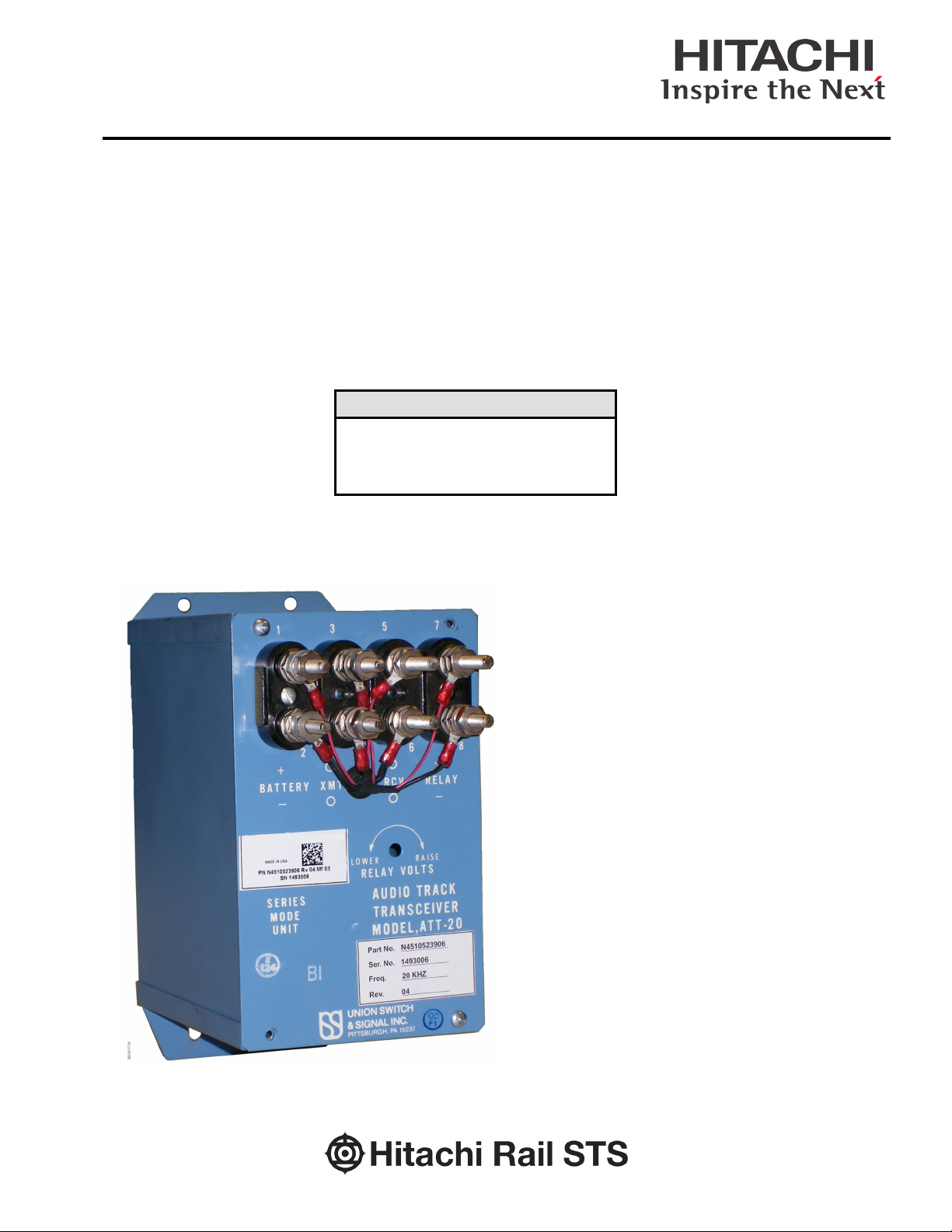
ATT-20 Audio Track Transceiver
through
Troubleshooting
Installation
Operation
Page 2

ATT-20 Audio Track Transceiver
Copyright 2019 SM 6299 Rev. 3, March 2019
Page 3

ATT-20 Audio Track Transceiver
Proprietary Notice
This document and the information contained therein are
confidential – the disclosure or other communication, copying,
reproduction and any use whatsoever is forbidden without the
written authorization of Hitachi Rail STS USA, Inc.
Important Notice
STS USA constantly strives to improve our products and keep our customers apprised
of changes in technology. Following the recommendations contained in the attached
service manual will provide our customers with optimum operational reliability. The data
contained herein purports solely to describe the product, and does not create any
warranties.
Within the scope of the attached manual, it is impossible to take into account every
eventuality that may arise with technical equipment in service. Please consult an STS
USA local sales representative in the event of any irregularities with our product.
STS USA expressly disclaims liability resulting from any improper handling or use of our
equipment, even if these instructions contain no specific indication in this respect. We
strongly recommend that only approved STS USA spare parts are used as
replacements.
©
Property of Hitachi Rail STS USA, Inc., 2019 all rights reserved– the copying,
reproduction and use of this work in any form whatsoever is forbidden without
the written authorization of Hitachi Rail STS USA, Inc.
1000 Technology Drive, Pittsburgh, PA USA 15219-3120
645 Russell Street, Batesburg, SC 29006
sts.hitachirail.com
Copyright 2019 SM 6299 Rev. 3, March 2019 i
Page 4

ATT-20 Audio Track Transceiver
0
April 1997
Initial issue
Revised to current template.
resolved.
Revised Figure 1-1 and Figure 6-1 to
Unit part numbers.
3
March 2019
Hitachi Rail STS Branding
Revision History
REV. DATE NATURE OF REVISION
Updated parts lists and drawings.
1.0 June 2008
2 December 2015
Incorporated ECO EE-1223 (2/00).
Miscellaneous minor grammatical
changes. Proof read comments
add R14 and label. Revised Table 6-4
and Figure 6-1 for items 126 and 127.
Revised Table 6-5
to correct ATT-20
Copyright 2019 SM 6299 Rev. 3, March 2019 ii
Page 5

ATT-20 Audio Track Transceiver
Table of Contents
1. GENERAL INFORMATION ............................................................................................................... 1-1
1.1. Introduction ............................................................................................................................... 1-1
1.2. Physical Description ................................................................................................................. 1-1
1.3. Specifications ............................................................................................................................ 1-1
1.3.1. Power Requirements .................................................................................................... 1-1
1.3.2. Transceiver Characteristics .......................................................................................... 1-2
1.3.3. Receiver Characteristics ............................................................................................... 1-2
1.3.4. Miscellaneous ............................................................................................................... 1-3
2. APPLICATION, INSTALLATION, AND ADJUSTMENTS ................................................................ 2-1
2.1. General ..................................................................................................................................... 2-1
2.2. Shunt Mode Track Circuit Application ...................................................................................... 2-1
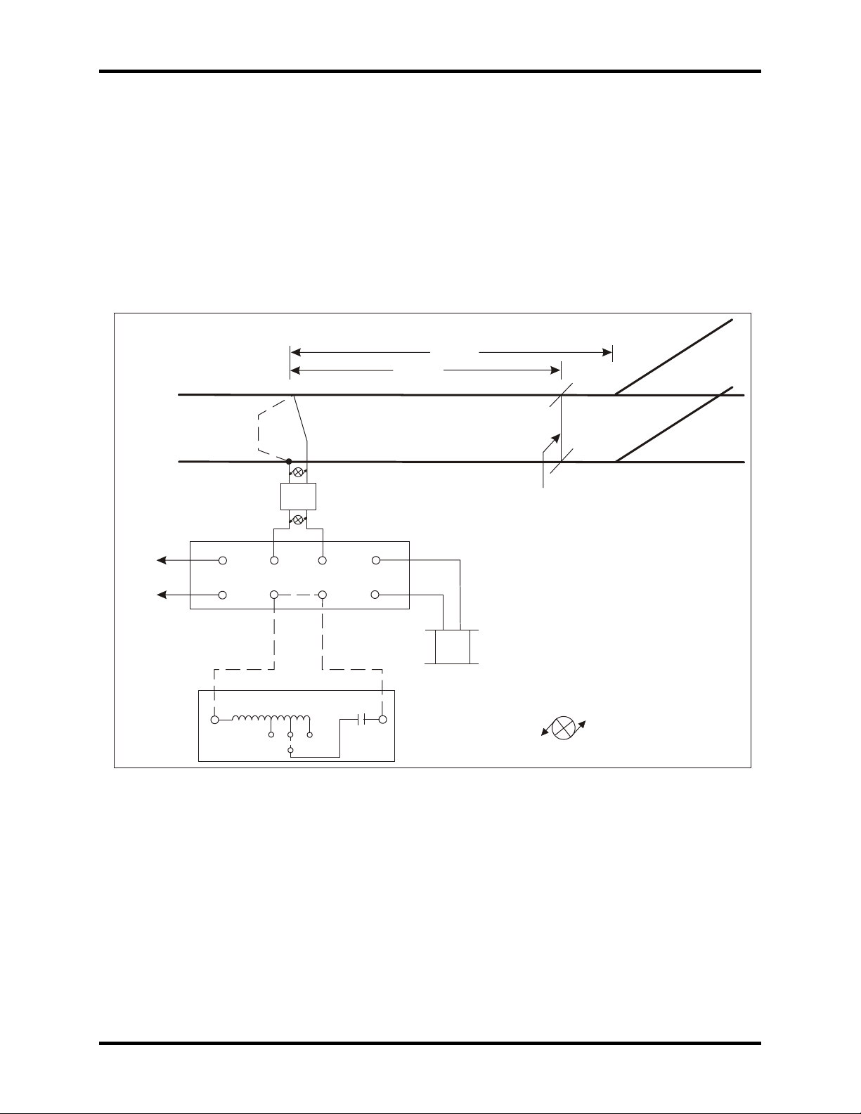
2.3. Series Mode Track Circuit Application ...................................................................................... 2-2
2.4. Terminal Connections ............................................................................................................... 2-3
2.5. Mounting Requirements ............................................................................................................ 2-3
2.6. General Considerations ............................................................................................................ 2-3
2.7. Shunt Mode Operation .............................................................................................................. 2-4
2.7.1. Shunt Mode Installation ................................................................................................ 2-4
2.7.2. Shunt Mode Adjustment ............................................................................................... 2-5
2.8. Series Mode Operation ............................................................................................................. 2-5
2.8.1. Series Mode Installation ............................................................................................... 2-6
2.8.2. Series Mode Adjustment without Cable Compensating PCB ....................................... 2-6
2.8.3. Series Mode Adjustment with Cable Compensating PCB ............................................ 2-7
2.9. Lightning Protection .................................................................................................................. 2-7
3. FUNCTIONAL DESCRIPTION .......................................................................................................... 3-1
3.1. General ..................................................................................................................................... 3-1
3.2. Shunt Mode Track Circuit ......................................................................................................... 3-1
3.3. Series Mode Track Circuit ........................................................................................................ 3-1
3.4. Detailed Circuit Description ...................................................................................................... 3-1
3.4.1. Transmitter .................................................................................................................... 3-1
3.4.2. Receiver ........................................................................................................................ 3-2
4. FIELD MAINTENANCE ..................................................................................................................... 4-1
4.1. General ..................................................................................................................................... 4-1
4.2. Test Equipment ......................................................................................................................... 4-1
4.3. General Checks ........................................................................................................................ 4-1
4.4. Shunt Mode Checks ................................................................................................................. 4-1
4.5. Series Mode Checks ................................................................................................................. 4-3
5. SHOP MAINTENANCE ..................................................................................................................... 5-1
6. PARTS LISTS .................................................................................................................................... 6-1
6.1. ATT-20 Audio Track Receiver Kits ........................................................................................... 6-1
Copyright 2019 SM 6299 Rev. 3, March 2019 iii
Page 6

ATT-20 Audio Track Transceiver
6.2. ATT-20 Audio Track Transceiver Units .................................................................................... 6-1
6.3. ATT-20 Audio Track Receiver Parts List .................................................................................. 6-2
6.4. Cable Compensating PCB Parts List ........................................................................................ 6-5
7. RAIL TEAM AND TECHNICAL SUPPORT ...................................................................................... 7-1
List of Figures
Figure 1-1. ATT-20 Dimensions ......................................................................................................... 1-3
Figure 2-1. Shunt Mode Track Circuit Application .............................................................................. 2-1
Figure 2-2. Series Mode Track Circuit Application ............................................................................. 2-2
Figure 2-3. Lightning Arrester and Surge Ripple Filter for Shunt Mode Application .......................... 2-9
Figure 2-4. Lightning Arrester and Surge Ripple Filter for Series Mode Application ....................... 2-10
Figure 3-1. Transmitter PCB Schematic Diagram .............................................................................. 3-3
Figure 3-2. Receiver PCB Schematic Diagram .................................................................................. 3-5
Figure 4-1. ATT-20 Test Circuit for Shunt Mode Application ............................................................. 4-2
Figure 4-2. ATT-20 Test Circuit for Series Mode Application ............................................................. 4-3
Figure 6-1. ATT-20 Parts Illustration .................................................................................................. 6-4
Figure 6-2. ATT-20 Wiring Diagram ................................................................................................... 6-5
Figure 6-3. Cable Compensating PCB Parts Layout and Schematic Diagram .................................. 6-6
List of Tables
Table 1-1. Adjacent Frequency Rejection ......................................................................................... 1-2
Table 2-1. Terminal Assignments...................................................................................................... 2-3
Table 2-2. Ring-by Parameters for 0.1 Ohm Shunting ...................................................................... 2-5
Table 2-3. Cable Length vs. Frequency ............................................................................................ 2-6
Table 6-1. ATT-20 Unit Kits ............................................................................................................... 6-1
Table 6-2. ATT-20 Unit (Only) ........................................................................................................... 6-1
Table 6-3. Miscellaneous Application Units ...................................................................................... 6-1
Table 6-4. ATT-20 Unit Parts List ...................................................................................................... 6-2
Table 6-5. ATT-20 Part Tabulation .................................................................................................... 6-3
Table 6-6. Cable Compensating PCB Parts List ............................................................................... 6-5
Copyright 2019 SM 6299 Rev. 3, March 2019 iv
Page 7

ATT-20 Audio Track Transceiver
1. GENERAL INFORMATION
1.1. Introduction
This manual provides application, installation and maintenance information for the STS
USA Audio Track Transceiver, Model ATT-20.
The ATT-20 is a short-range transceiver operating in the audio frequency range of 12 to
20 KHz. The high frequency range was chosen to provide sharp block definition. The
ATT-20 can be used in applications such as highway crossings, island circuits, switch
lock release and general train detection in non-electrified and DC electrified territories.
In most cases, insulated joints are not required and track circuits up to 300 feet in length
can be realized. Units are available for operation in either shunt mode or series mode
applications.
1.2. Physical Description
The ATT-20 is a single unit transceiver containing separate transmitter and receiver
printed circuit boards, mounted on a common chassis. The chassis is housed in a sheet
metal box. The top cover of the unit is the faceplate to which Association of American
Railroads (AAR) terminal posts are mounted.
1.3. Specifications
1.3.1. Power Requirements
Power Supply Voltage: 9.8 - 15.2 VDC
Maximum Ripple: 1 Vpp
Load Current: 600 mA.
Fuse: 3 / 4 Amp fast blow
Copyright 2019 SM 6299 Rev. 3, March 2019 1-1
Page 8
ATT-20 Audio Track Transceiver
1.3.2. Transceiver Characteristics
CAUTION
The ATT-20 may be operated from a constant potential
rectifier (CPR) supply, batteries floating on a CPR, or an
electronically regulated supply. Regardless of the supply
used, a surge ripple filter (STS USA N451590-0301) must be
used between the supply and the ATT-20 Transceiver.
Shunt Mode Output Voltage: 1.0 Vrms (modulated) into a 5-ohm load
Series Mode Output Voltage: 0.25 Vrms (modulated) into a 1-ohm load
Available Operating Frequencies: 12.28 KHz, 15.0 KHz, 20 KHz.
Carrier Frequency Tolerance: + 0.5 %
Modulation Frequency (All Units): 390 Hz + 0.5%
Harmonic Output: -30 dB at second harmonic with 12 ohm load in shunt
mode
7 ohm shunt mode; 1 ohm series mode
1.3.3. Receiver Characteristics
Sensitivity: 70 mVrms (modulated signal) + 14 mV
Input Impedance: 7 ohms shunt mode, 1 ohm series mode
Output Voltage: 7.65 VDC into 400 ohms
Table 1-1. Adjacent Frequency Rejection
ATT-20 Frequency
(KHZ)
12.28 15.0 -18.0
15.0
20.0
Adjacent Frequency of
Concern (KHz)
12.28
18.0*
20.0
15.0
18.0*
Rejection of Adjacent
Frequency (dB)
* Of concern where joint detectors are used.
-30.0
-21.0
-27.0
-44.0
-23.0
Copyright 2019 SM 6299 Rev. 3, March 2019 1-2
Page 9
ATT-20 Audio Track Transceiver
RCV
(REF)
2
AUDIO TRACK
TRANSCEIVER
MODEL,ATT-20
(REF)
LOWER
6 1/16
2 1/8
8
+
RE LAY
-
(REF)
TL5
TL6
SHUNT
MODE
UNIT
2 1/4 (REF)
PC.NO.
SER.NO.
FREQ.
RE V.
7 5/8
4
5
8
7
(REF)
+
BAT TE RY
-
XMT
1
4 5/8
(REF)
9 /41
3
RE LAY VO LTS
TL1
RAISE
(REF)
6
TL2
TL3
TL4
3B3.0001.01
R14
1.3.4. Miscellaneous
Reverse battery protection: Built-in
Operating temperature range: - 40°C to +70°C
Maximum block length: 300 ft. shunt mode at 3 ohm/1000 ft. ballast; 150 ft.
series mode at 3 ohms/1000 ft. ballast.
Recommended Relay: PN-150B, 400 ohm coil, (STS USA N322500-
701)
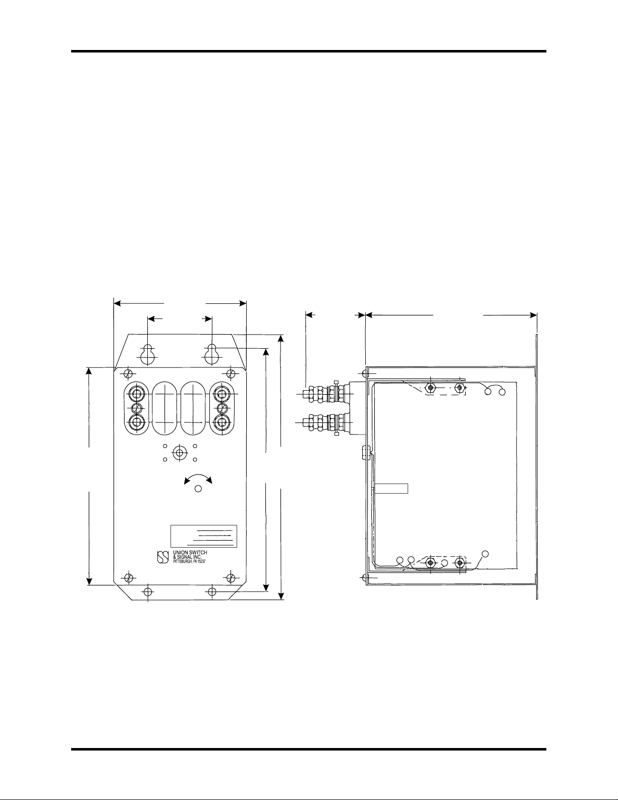
Overall Dimensions: Refer to Figure 1-1.
Mounting Hole Dimensions: 2¼" x 8½"
Weight: 4 lbs., 14 oz.
Terminal Connections: AAR
Copyright 2019 SM 6299 Rev. 3, March 2019 1-3
Figure 1-1. ATT-20 Dimensions
Page 10

ATT-20 Audio Track Transceiver
Copyright 2019 SM 6299 Rev. 3, March 2019 1-4
Page 11
ATT-20 Audio Track Transceiver
300 FEET
MAX.
RING-BY
USSP-21
USSP-21
1
1
2
2
3
3
4
4
TO
BATTERY
1
2
3
4
5
6
7
8
TWISTED PAIR
ATT-2 0
HARD-WIRE SHUNT
USED DURING
SET-UP
3B3.0002.01
2. APPLICATION, INSTALLATION, AND ADJUSTMENTS
2.1. General
This section provides information on the application of the ATT-20, as well as
installation and adjustment procedures for the ATT-20 and related equipment. It is also
critical that this section be read in its entirety prior to any application considerations.
2.2. Shunt Mode Track Circuit Application
In this application, the transmitter output and receiver input are connected by cable
directly to the rails. The connection is made through surge protectors by twisted line
pairs as shown in Figure 2-1. The point at which the transmitter wires are connected
defines one end of the track circuit. While the other end of the track circuit is defined by
the receiver connections to the track. The receiver detects the presence of a train by the
loss of the audio frequency signal that is shunted away by the train axle.
The shunt mode of operation is defined as a vital application.
Figure 2-1. Shunt Mode Track Circuit Application
Copyright 2019 SM 6299 Rev. 3, March 2019 2-1
Page 12
ATT-20 Audio Track Transceiver
75 FEET
60 FEET
ADJUSTMENT
SHUNT
“O”
OHM SHUNT
USSP-21
_
+
TWISTED PAIR
ATT-20
1
2
3
4
12V
BATTERY
1
3
5 7
2 4 6
8
1
L1
T1
T2 T3
CT
C1 2
CABLE COMPENSATING PCB
3B3.0003.
00
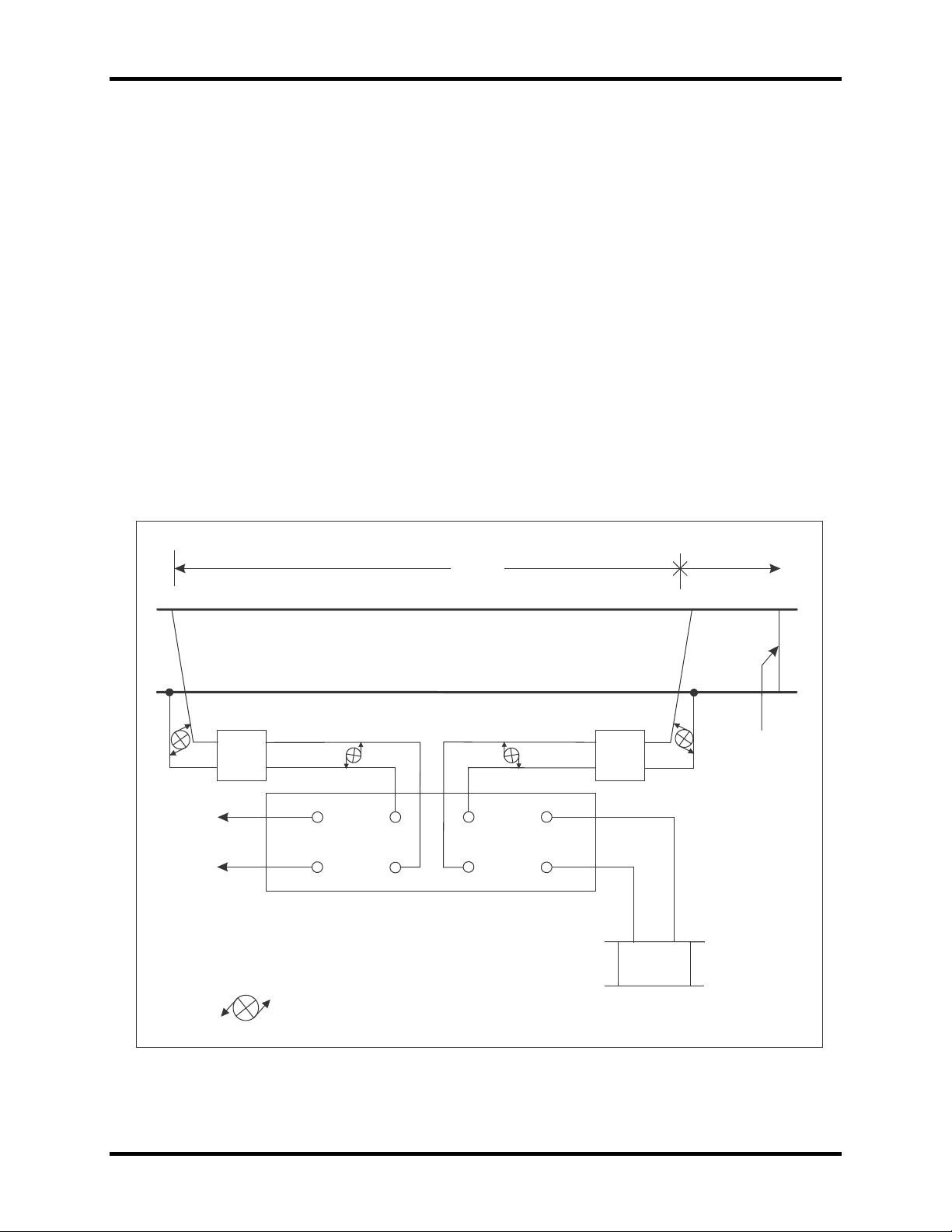
2.3. Series Mode Track Circuit Application
In this application, the transmitter and receiver are wired in sequence via a jumper on
the ATT-20 unit. This jumper connects transmitter output terminal 4 to the receiver input
terminal 6. The remaining transmitter output lead (terminal 3) and the remaining
receiver lead (terminal 5) are twisted as a pair and each is connected to its respective
rail (see Figure 2-2). The presence of a train axle across the rails completes the series
signal path, thus detecting the approach of a train.
The series mode of operation is a non-vital application.
Figure 2-2. Series Mode Track Circuit Application
Copyright 2019 SM 6299 Rev. 3, March 2019 2-2
Page 13

ATT-20 Audio Track Transceiver
2.4. Terminal Connections
AAR type terminals are located on the top of the unit for making external connections.
Refer to Table 2-1 for terminal assignments.
Table 2-1. Terminal Assignments
Terminal No. Description
1 + Battery
2 - Battery
3 Transmitter Lead
4 Transmitter Lead
5 Receiver Lead
6 Receiver Lead
7 + Relay
8 - Relay
Internal wiring is accessed through a hole with a grommet around it in the faceplate.
Also located on the faceplate is an access hole which is intended for setting transmitter
gain. This is a simple adjustment and can be accomplished with a screwdriver.
2.5. Mounting Requirements
A convenient mounting bracket, which is an integral part of the case, provides four holes
spaced 2-1/4 x 8-1/2 apart to facilitate wall, shelf or rack mounting.
2.6. General Considerations
• Track leads to the transmitter and receiver must be a #9 AWG or heavier twisted
pair.
• Power supply must be 9.8 - 15.2 VDC and capable of supplying 1 ampere. A
surge ripple filter (STS USA Part No. N451590-0301) must be used between any
supply and the ATT-20. Power supply ripples must not exceed 1.0 Vpp.
• Use higher frequency units when less ring-by is desired.
• Provide lightning protection per Section 2.9.
• The relay recommended to be used with ATT-20 is a vital PN-150B, STS USA
No. N322500-701, 400 ohm, plug-in type.
Copyright 2019 SM 6299 Rev. 3, March 2019 2-3
Page 14

ATT-20 Audio Track Transceiver
2.7. Shunt Mode Operation
CAUTION
When using the shunt track circuit configuration, do not
repeat the use of the same frequency unless circuits are
isolated by at least two (2) insulated points.
Where less ring-by is desired, keep the track circuit length to
a minimum and use the shortest possible track leads. Refer
to Figure 2-1 and Table 2-2 for shunt track circuit application.
2.7.1. Shunt Mode Installation
Refer to Figure 2-1 and proceed as follows to install the ATT-20 in shunt mode
application:
1. Connect transmitter terminals 3 and 4 to terminals 3 and 4 of the USS-21 surge
suppressor. Continue the cabling to the track from terminals 1 and 2 of the
USSP-21. Repeat the above procedure for cabling receiver input terminals 5 and
6 to the rails. All transmitter and receiver cables must be #9 AWG or heavier and
used as a twisted pair. Ensure the combined lengths of the transmitter and
receiver cables do not exceed 500 ft. Also, do not exceed block lengths of 300 ft.
2. Connect terminals 7 (relay +) and 8 (relay -) to the relay. The recommended relay
to be used with the ATT-20 is a PN-150B, 400 ohm plug-in type, STS USA Part
No.: N322500-701.
3. If the ATT-20 is to receive its DC power from a battery or constant potential
rectifier supply (CPR) or an electronically regulated supply, a surge ripple filter
(Part No. N451590-0301) must be used as follows:
a. Connect terminals 1 (+) and 2 (-) of the ATT-20 to respective "+DC" and "-
DC" terminals of the ripple filter. See Figure 2-3.
b. Jumper terminals 2 to N on the ripple filter and cable terminals B (positive)
and N (negative) to their respective battery bus or supply terminals. Lightning
arrestor USG-A N451552-0101 should be across ripple filter terminals B and
N. Refer to Section 5 for the details on lightning protection.
4. If the ATT-20 is to be powered from an electronic supply, this supply should be
capable of delivering 1.0 ampere at 12 VDC (on the ATT-20 side of the surge
ripple filter) and be dedicated to the ATT-20 that it is powering.
Copyright 2019 SM 6299 Rev. 3, March 2019 2-4
Page 15
ATT-20 Audio Track Transceiver
12.28 KHZ
15.0 KHz
20.0 KHz
100
11
10
9
2.7.2. Shunt Mode Adjustment
Proceed as follows to adjust the ATT-20 in a shunt mode installation:
1. Connect a hard-wire shunt across the rails outside of the defined block at the
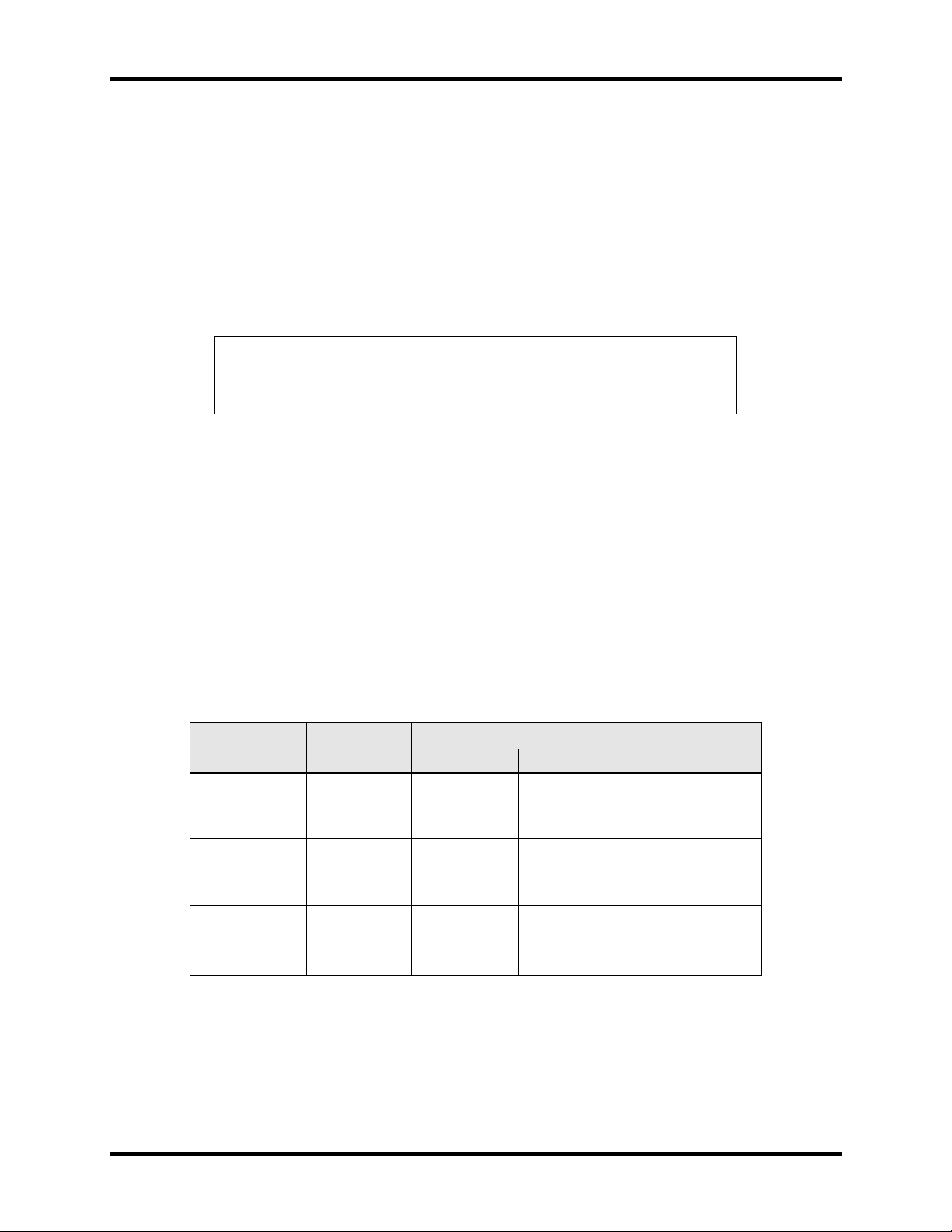
desired ring-by distance from the ATT-20 receiver track connections (terminals 5
and 6). Table 2-2 shows typical ring-by parameters for 3.0 ohm/1000 ft. ballast
and 0.1 ohm adjustment shunt.
Note
The adjustment shunt mentioned below is not a hard-wire
shunt. The resistance of the adjustment shunt must
accurately represent the desired shunting sensitivity.
2. Adjust the ATT-20 transmitter output level through the access hole in the top
cover until the relay is energizes.
3. Remove the hard-wire shunt from the rails.
4. Place an adjustment shunt across the rails at the receiver connection (not the
ring-by distance). The relay should deenergize. A compromise between the
shunting sensitivity (adjustment shunt) and ring-by distance will be achieved per
application.
5. Remove the adjustment shunt from the rails. The adjustment procedure is
complete.
Table 2-2. Ring-by Parameters for 0.1 Ohm Shunting
Track Length
(Ft.)
100
200
300
Total Cable
Length (Ft.)
300 14 14 13
500 19 19 19
200 18 18 17
300 21 21 22
500 29 29 33
300 30 30 33
400 35 36 41
500 40 43 52
Typical Minimum Ring-By (Ft.)
2.8. Series Mode Operation
Series track circuit locations operating at the same frequency must be separated by at
least two insulated joints. A typical series mode application would be at a switch lock.
Copyright 2019 SM 6299 Rev. 3, March 2019 2-5
Page 16

ATT-20 Audio Track Transceiver
-3904
12.28
< 75 feet
T3
-3905
15
< 50 feet
T2
2.8.1. Series Mode Installation
Refer to Figure 2-2 and proceed as follows to install the ATT-20 in a series mode
application:
1. Connect a jumper strap between terminals 4 and 6 on the ATT-20 when the total
single conductor cable length from the ATT-20 to the track is less what appears
in Table 2-3 below. If the cable length is exceeded, connect terminals 4 and 6 on
the ATT-20 to terminals 1 and 2, respectively, of the cable compensating circuit
board (N131002-01). The cable compensating PCB is part of an ATT-20 kit. See
Section 6.1 for part numbers.
Table 2-3. Cable Length vs. Frequency
Suffix No.
N451052-
-3906 20 < 25 feet T1
Frequency
(KHz)
Total Cable Length
(Length x 2 cond.)
Jumper from Cable Compensating
PCB to Terminal:
2. Connect terminals 3 and 5 to terminals 3 and 4 of the USSP-21 surge
suppressor.
3. Connect terminals 1 and 2 of the USSP-21 to the track at a point 75 feet from the
switch points. All cabling from the ATT-20 to the track must be #9 AWG or
heavier twisted pair.
4. Connect terminals 7 (relay +) and 8 (relay -) to the relay. The recommended relay
to be used with the ATT-20 is a PN-150B, 400 ohm, plug-in type, Part No.
N322500-701.
5. If the ATT-20 is to receive its DC power from a battery, constant potential rectifier
supply (CPR), or an electronically regulated supply, a surge ripple filter (Part No.
N451590-0301) must be used as follows:
• If the ATT-20 is to be powered from an electronic supply, this supply should
be capable of delivering 1.0 ampere at 12 VDC (on the ATT-20 side of the
surge ripple filter) and be dedicated to the ATT-20 it is powering.
2.8.2. Series Mode Adjustment without Cable Compensating PCB
Proceed as follows to adjust the ATT-20 in a series mode, without cable compensating
PCB installation:
1. Connect a hardwire shunt across the rails 65 feet from the ATT-20 track
connections.
2. Adjust the ATT-20 transmitter output level through the access hole in the top
cover until the relay is just energized.
Copyright 2019 SM 6299 Rev. 3, March 2019 2-6
Page 17

ATT-20 Audio Track Transceiver
3. Remove the hardwire shunt from the rails. The adjustment procedure is
complete.
2.8.3. Series Mode Adjustment with Cable Compensating PCB
Proceed as follows to adjust the ATT-20 in a series mode, with cable compensating
PCB installation:
1. Place a zero ohm shunt across the track connections at the feed end.
2. Connect an AC voltmeter (Vrms) across terminals 5 and 6 on the ATT-20.
3. On the cable compensating PC board, adjust the slug in pot core inductor L1 until
the voltmeter indicates a maximum.
Note
Depending on cable length, peaking of the signal might not
be possible. After adjustment of inductor, place a small
amount of RTV in the pot core adjuster area.
4. Remove the zero ohm shunt.
5. Connect a hardwire shunt across the rails 65 feet from the ATT-20 track
connections.
6. Adjust the ATT-20 transmitter output level through the access hole in the top
cover until the relay is just energized.
7. Remove the hardwire shunt from the rails. The adjustment procedure is
complete.
2.9. Lightning Protection
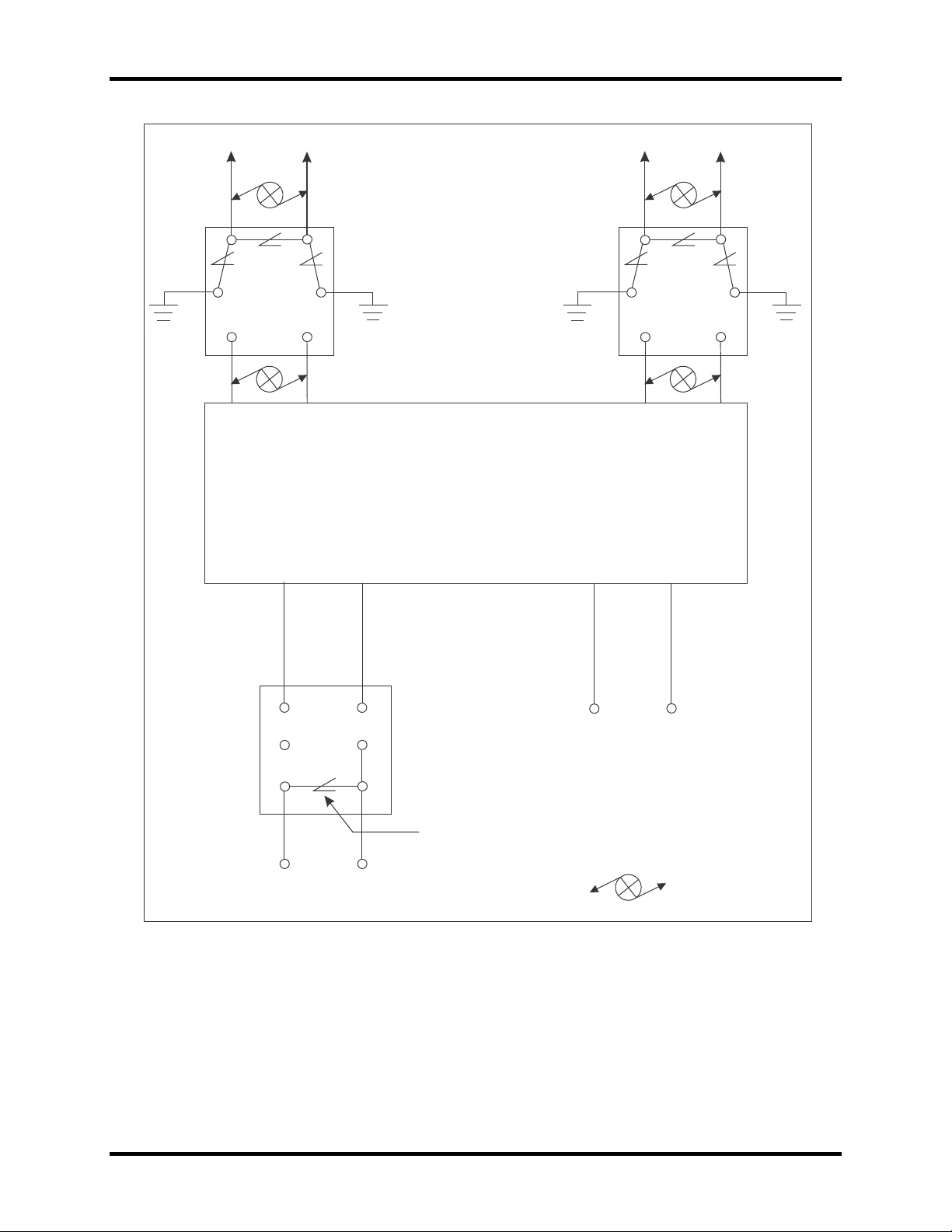
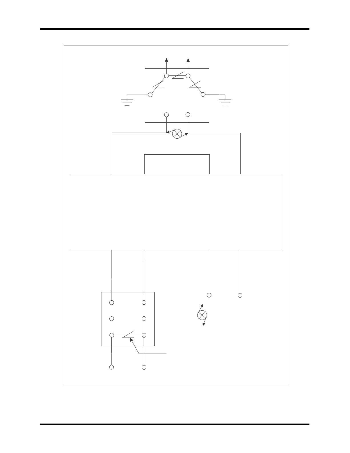
Block wiring diagrams showing the wiring of surge and ripple protection for the ATT-20
in both the shunt and series modes of operation appear in Figure 2-3 and Figure 2-4,
respectively.
Two lightning protection devices are to be used with the ATT-20. The track connections
will be made through a USSP-21 secondary surge protection and the battery power
supply line will be protected by a surge ripple filter that uses a USG-A lightning arrester
across the power bus terminals.
The USSP-21 surge protector is wired to permit line-to-line protection using a low
voltage arrester and line-to-ground protection using high voltage arresters. Internal
circuitry of the USSP-21 also includes series line inductors as well as back-to-back
Copyright 2019 SM 6299 Rev. 3, March 2019 2-7
Page 18

ATT-20 Audio Track Transceiver
Zener diodes for suppression of low voltage transients. The STS USA part no. is
N451552-0525.
The surge ripple filter consists of a series line inductor and a four-terminal capacitor with
a selenium suppressor diode across its terminals. The four-terminal capacitor
guarantees loss of power to the load should one of the capacitor leads or plates open.
The line-to-line arresters used across terminals 1 and 2 of the USSP-21 and terminals B
and N of the Surge Ripple Filter are USG-A N451552-0101.
The line-to-ground arresters used across terminals 1 and 5, 2 and 6 of the USSP-21are
USG-A N451552-0201.
Copyright 2019 SM 6299 Rev. 3, March 2019 2-8
Page 19
ATT-20 Audio Track Transceiver
TO
TRACK
1
2
5
6
3
4
USSP-21
TO
TRACK
1
2
5
6
3
4
USSP-21
3 4
TRANSMITTER
5
6
RECEIVER
ATT-2 0
+
+
+
_
_
_
DC
DC
DC
DC
RE LAY
1
2
7 8
SURGE RIPPLE
FILTER
(N451590-0301)
4 2
B N
LIGHTNING ARRESTER
PART NO. N451552-0101
TO
BATTERY
OR
POWER
SUPPLY
TWISTED PAIR
3B3.0004.01
Figure 2-3. Lightning Arrester and Surge Ripple Filter for Shunt Mode
Application
Copyright 2019 SM 6299 Rev. 3, March 2019 2-9
Page 20
TO
TRACK
1
2
5
8
USSP-21
3
4
3
4
6
5
TRANSMITTER
RECEIVER
ATT-20
1 2
7
8
+ DC
_
DC
+
_
RE L AY
TWISTED PAIR
+
_
DC
DC
4
B
N
2
TO
BATTERY
OR
POWER
SUPPLY
LIGHTNING ARRESTER
PART NO. N451552-0101
3B3.0005.01
ATT-20 Audio Track Transceiver
Figure 2-4. Lightning Arrester and Surge Ripple Filter for Series Mode
Application
Copyright 2019 SM 6299 Rev. 3, March 2019 2-10
Page 21

ATT-20 Audio Track Transceiver
Copyright 2019 SM 6299 Rev. 3, March 2019 2-11
Page 22

Page 23

ATT-20 Audio Track Transceiver
3. FUNCTIONAL DESCRIPTION
3.1. General
The transmitter produces an output signal in the high audio frequency range and is sine
wave modulated to provide noise immunity. First, the receiver detects the modulation
information signal. It then amplifies and rectifies this signal to provide a DC output which
drives the relay coil. The functional description of the ATT-20 applied to the shunt track
circuit is covered in Section 3.2. Section 3.3 covers the series mode track circuit.
3.2. Shunt Mode Track Circuit
As illustrated in Figure 2-1, the transmitter output and receiver input are cabled directly
to the rails. The point at which the transmitter wires are connected defines one end of
the track circuit. The other end of the track circuit is defined by the receiver connections
to the track. The receiver detects the presence of a train by the loss of the audio
frequency signal which is shunted away by the train axle.
The shunt mode of operation is defined as a vital application.
3.3. Series Mode Track Circuit
As illustrated in Figure 2-2, the transmitter and receiver are wired in series via a jumper
located on the ATT-20 unit. This jumper connects the transmitter output terminal to the
receiver input terminal. The remaining transmitter output lead and the remaining
receiver lead are twisted as a pair with each is connected to its respective rail. The
presence of a train axle across the rails completes the series signal path, thus detecting
the presence of a train
The series mode of operation is a non-vital application.
3.4. Detailed Circuit Description
3.4.1. Transmitter
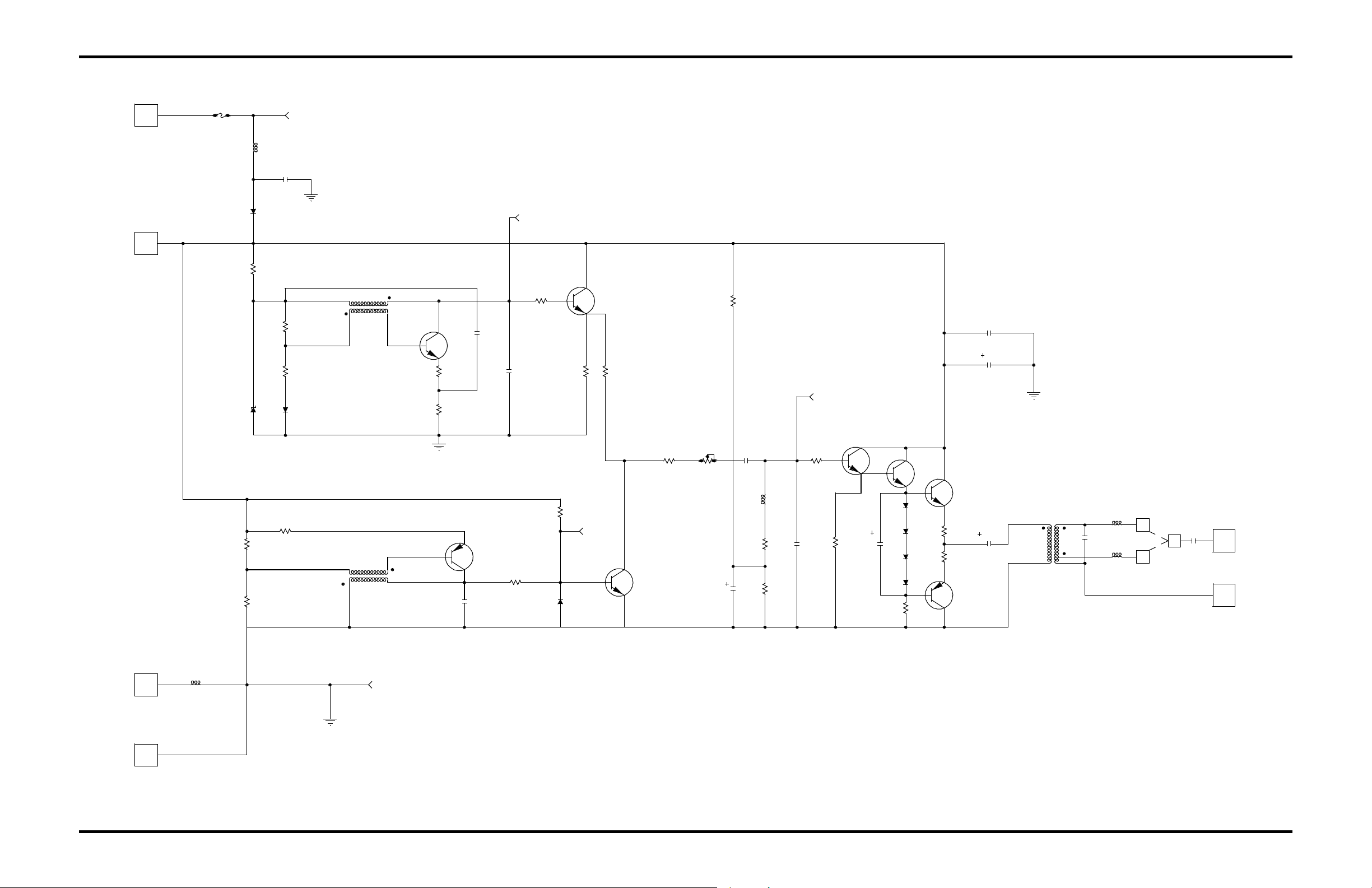
The transmitter circuit diagram is shown in Figure 3-1. Transistor Q1 and its associated
circuitry comprise the modulation oscillator which produces 390 Hz. A constant signal
level is maintained by Zener diode D1. Transistor Q2 buffers the modulation oscillator.
Transistor Q7 and its associated circuitry comprise the carrier frequency oscillator.
Selection of capacitor C3 determines the carrier frequency.
Transistors Q3, R8 and R13 mix the carrier and modulation signals. Resistor R14
provides gain control. Inductor L1, capacitor C5, and resistor R17 form a bandpass filter
which allows the modulated carrier to pass unaltered by low frequency or higher order
harmonic disturbances.
Copyright 2019 SM 6299 Rev. 3, March 2019 3-1
Page 24

ATT-20 Audio Track Transceiver
Resistor R15 and R19 form a voltage divider which sets the bias for transistor Q4.
Capacitor C12 bypasses resistor R19. Transistors Q4, Q5, Q6 and Q8 make up a unity
gain amplifier with low output impedance. Diodes D4, D5, D6 and D8 - along with
resistors R20 and R21 - serve to temperature compensate and bias both transistors Q5
and Q6. C13 is a bypass capacitor. Capacitor C6 and the primary of T3 couple the
signal to the output circuitry.
Inductor L5, jumper J2 and capacitor C9 from the shunt mode output, provide an output
impedance of 7 ohms.
Inductor L6, jumper J1 and capacitor C9 form the series mode output provide an output
impedance of 1 ohm.
Diode D7 prevents damage from reverse battery connection. Fuse F1 prevents damage
from an overcurrent condition. Inductors L2, L3 and capacitor C11 provide RFI rejection.
Capacitors C7 and C10 filter the power bus.
3.4.2. Receiver
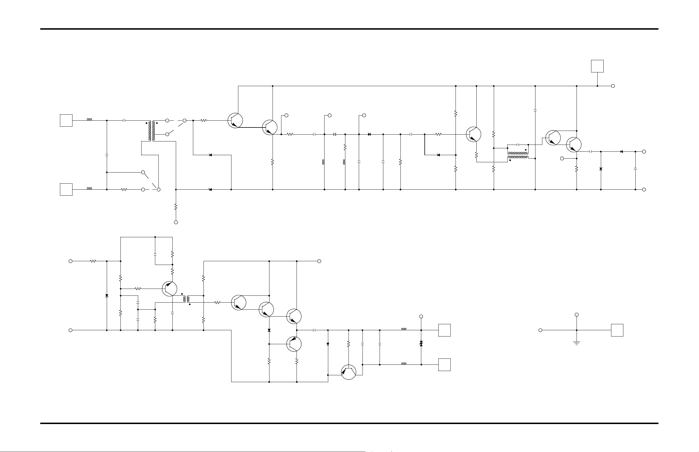
The receiver circuit diagram is shown in Figure 3-2. Capacitor C1, transformer T1 and
resistor R1 form a medium Q input filter. Jumper positions should be J1 and J3 for both
shunt and series mode boards. The input impedance is primarily determined by R1
(Shunt boards = 7 ohms, series boards = 1 ohm). Transistors Q1 and Q2 form a
Darlington pair emitter follower which buffers the input signal. Resistor R4 and Zener
diode D10 provide a fixed bias voltage for Q1 and Q2.
Inductors L3 and L4; capacitor C3, C4 and C5; and resistors R6 and R7, together form
a high Q bandpass filter. Diode D1 demonstrates the signal. Resistor R8 and capacitor
C6 filter the carrier frequency. Transistor Q3 and its associated circuitry form an emitter
follower to buffer the demodulated signal. Resistor R13 is selected to provide an input
sensitivity of 70 mVrms (modulated signal).
Transformer T2 and capacitor C9 form the demodulated filter. Transistors Q4 and Q5
are con-figured as an emitter follower which buffers the demodulated signal. Capacitors
C11 and C12, along with diode D3 and D4, form a voltage doubler. This doubler
produces a negative DC voltage which drives a level detector.
The level detector consists of resistor R17 and diode D5. Once in conduction, D5
provides the feedback path necessary for Q6 and its associated circuitry to behave as
an oscillator. The oscillator frequency is approximately 25 KHz. The output of the
oscillator is buffered by transistor Q7 and Q10. Transistors Q8 and Q9 amplify the
signal. Diodes D7 and Q11, along with capacitors C17 and C8, form a voltage doubler.
They also rectify and filter the signal to provide a negative DC voltage to drive an
external relay. The Q11 circuit decreases relay drop away time in lieu of the standard 2diode voltage doubler circuit. Inductors L1, L2, L6, and L7 (along with capacitors C19
and C7) provide RFI rejection. Capacitor C10 filters the power bus.
Copyright 2019 SM 6299 Rev. 3, March 2019 3-2
Page 25
ATT-20 Audio Track Transceiver
15T
R20
D8
2N60 59
Q5
2N227 0
Q8
100uf
C6
0.5
R21
0.5
2N6052
Q6
D6
R18
470
D5
TL6
C9
.47uf
SHUNT
COMJ1
J2
SERIES
.47uf
L5
C8
T3
6T
26T
L6
TP5
GND
TL4
L2
B-
TL3
T2
2N 3117
820K
R2
1K
VSK130
D7
.01uf
C11
TP4
L3
Q4
.22uf
R6
C1
1.0uf
+
R15
1K
L1
1K
1328T
LVA4 50
D1
390K
R3
C13
3.0K
R19
1N9 14
1N914
10K
R16
TP3
C4
1M
R14
3 3K
R13
1N914
D3
TP1
3.6M
R22
470K
R12
TAB .
C3
10K
R8
2N3964
Q7
R7
10K
258T
26T
.15u f
C2
8.2K
R11
10K
R5
5.1K
R4
5 .1K
3.3K
R9
R1 0
Q1
T1
R1
332T
D2
1N914
TAB .
6.8uf
10K
R23
C5
TAB.
R17
1N914
2N 3117
47uf
C12
2N 3117
Q3
2N 3117
Q2
TP2
TL2
POWE R
1- 1/2 A
F1
TL1
B+
1N9 14
TRACK
TL5
TRACK
47uf
C7
.01uf
C10
D4
3B3.0010.
00
Copyright 2019 SM 6299 Rev. 3, March 2019 3-3
Figure 3-1. Transmitter PCB Schematic Diagram
Page 26
ATT-20 Audio Track Transceiver
Copyright 2019 SM 6299 Rev. 3, March 2019 3-4
Page 27
C
20K
R24
R17
A
C19
R1
J2
.01uf
J1TAB
TL1
B
T1
TAB .
TA B
1ST
2N4037
Q11
6.8uf
1N4003
L4
TP6
R7
TAB
TA B.
TP2
TA B.
100
R5
TBD
D10
2N2270
1N4003
2N 3117
Q1
D9
R2
LVA462
Q2
R6 C3 C4
680
.027uf
C16
2ND1ST
T3
2N 311 7
Q6
300
R23
10K
R22
C
TP4
TL6
1.5K E16CA
L7
D11
L6
2N 311 7
Q7
TRACK
TRACK
1.5K
T2
R15
1K
R14
TBD
R13
2N 3117
Q3
10K
R12
Q4
47uf
C10
47K
R11
.0033uf
TAB .
C5
1N4936
+
5uf .01uf
C7R32KC18
D1 C8 R10
D2
1K
1N914
C
D4
1N4003
POWER
+
C12
10uf
TL3
B
A
.02uf
C6
TAB
TAB .
L3
TP1
C15
.1uf
R21
2.4K
10K
R4
2ND
J4
J3
R20
L2
TL2
C1L1
Q10
24K
R25
2K
R26
20
R28
VSK130
D7
680
2N4037
R27
Q9
+
C17
2N3053
Q8
D6
2N2270
TP5
C11
+
2N2270
Q5
B
RE L AY -
200K
R8
.56uf
C14
270K
R19
.027uf
C13
2K
GND
TL4TL5
1.8K
RE LAY +
D5
LVA 45 0
240K
R18
2N 3117
1ST
C9
.15uf
2ND
10uf
R16
100 1N4003
TP3
D3
3B3.0009.00
ATT-20 Audio Track Transceiver
Copyright 2019 SM 6299 Rev. 3, March 2019 3-5
Figure 3-2. Receiver PCB Schematic Diagram
Page 28
ATT-20 Audio Track Transceiver
Copyright 2019 SM 6299 Rev. 3, March 2019 3-6
Page 29

ATT-20 Audio Track Transceiver
4. FIELD MAINTENANCE
4.1. General
The following procedures may be used to check the ATT-20 at its field installation.
These procedures should also reveal whether the fault is in the ATT-20 or a related unit
or circuit. If fault lies with the ATT-20, the ATT-20 should be replaced with a new unit.
When installing the new unit, please make certain to follow all installation procedures
outlined in Section 2. Replacement units may be obtained through the STS USA Sales
Office.
4.2. Test Equipment
• True RMS reading DMM (Fluke 8010A or equivalent).
• 5.0 ohm, 5 watt resistor 1%
• 1.0 ohm, 5 watt resistor 1%
4.3. General Checks
Proceed as follows to perform a general check of the ATT-20 unit before performing a
series mode or shunt mode check:
1. Inspect all leads for breaks and loose terminal connections.
2. Check power supply voltage at terminals 1 (+) and 2 (-). The voltage should be
12 VDC nominal (9.8 minimum to 15.8 VDC maximum). Ripple voltage should
not exceed 1.0 Vpp.
3. Check the fuse on the transmitter circuit board. If it is open, replace it with a 3.4
Amp fast-blow fuse. If the fuse is intact, disconnect the transmitter and receiver
track connections at the unit. To test for proper operation in the shunt mode, refer
to Section 4.4. To test for proper operation in the series mode, refer to Section
4.5.
4.4. Shunt Mode Checks
Proceed as follows to perform a shunt mode check:
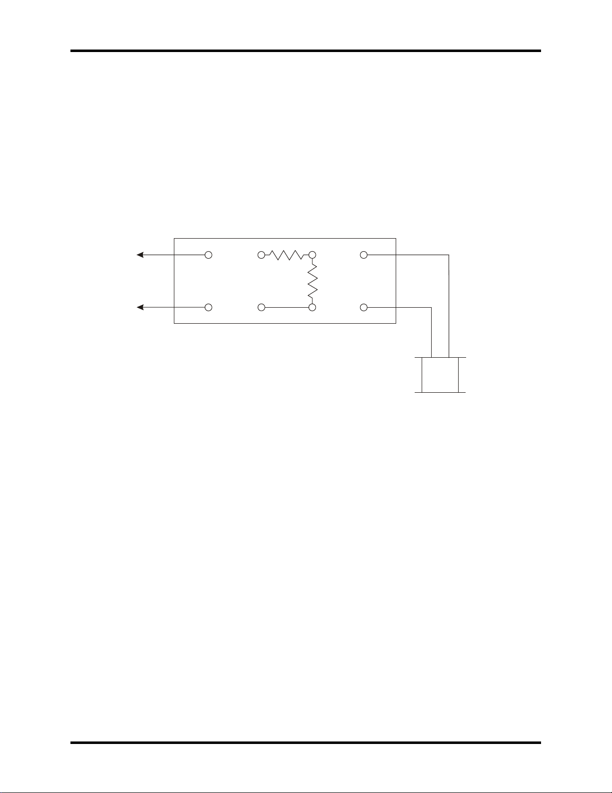
1. Connect the ATT-20 as shown in Figure 4-1.
2. Turn the RELAY VOLTS potentiometer fully clockwise. If the relay energizes,
proceed to step 3. If the relay does not energize, check the relay connections for
proper polarity and open circuits. If the same relay connections are good, replace
the ATT-20 with one of a unit of the same operating frequency and repeat steps
1 and 2. If the relay still does not energize, replace it with another PN-150B, 400
ohm coil (STS USA Part No. N322500-701).
Copyright 2019 SM 6299 Rev. 3, March 2019 4-1
Page 30
ATT-20 Audio Track Transceiver
12V
BATTERY
+
_
1
2
3
4
5
6
7
8
_
+
PN150B
REL AY
1.0
OHM
5.0 OHM
ATT-20
3B3.0011.00
3. If the relay does energize, disconnect the resistor between terminals 3 and 5,
and disconnect the jumper between terminals 4 and 6. Measure the open circuit
voltage across terminals 3 and 4. The voltage should be equal to or greater than
2.3 Vrms. If this voltage should be equal to or greater than 2.3 Vrms, reconnect
the resistor between terminals 3 and 5, and reconnect the jumper between
terminals 4 and 6. Adjust the transmitter level so that it just energizes the relay.
Measure the voltage across terminals 5 and 6 (receiver input). This voltage
should be 70 mVrms + 14 mVrms. If not, replace the ATT-20 unit.
Figure 4-1. ATT-20 Test Circuit for Shunt Mode Application
The tests performed in Section 4.4 verify proper operation of the ATT-20 unit in a shunt
mode application. If the track circuit installation still does not work properly, troubleshoot
the cabling, connections, and peripheral equipment associated with the track circuit.
Copyright 2019 SM 6299 Rev. 3, March 2019 4-2
Page 31
ATT-20 Audio Track Transceiver
12V
BATTERY
+
_
1
2
3
4
5
6
7
8
_
+
PN150B
REL AY
1.0 OHM
ATT-20
3B3.0012.00
4.5. Series Mode Checks
Proceed as follows to perform a series mode check:
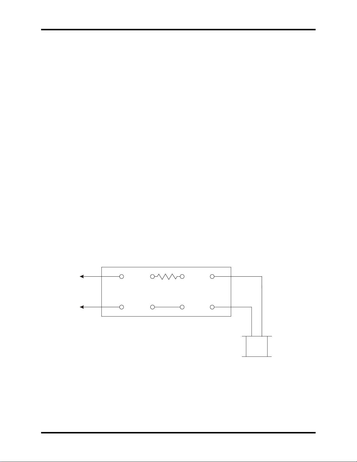
1. Connect the ATT-20 as shown in Figure 4-2.
2. Turn the RELAY VOLTS potentiometer fully clockwise. If the relay energizes,
proceed to step 3. If the relay does not energize, check the relay connections for
proper polarity and open circuits. If the relay connections are good, replace the
ATT-20 with a unit of the same frequency and then repeat steps 1 and 2. If the
relay still does not energize, replace the relay with another PN-150B, 400 ohm
coil (STS USA Part No. N322500-701).
3. If the relay energizes, disconnect the resistor between terminals 3 and 5, and
disconnect the jumper between terminals 4 and 6. Measure the open circuit
voltage across terminals 3 and 4. This voltage should be greater than or equal to
0.4 Vrms. Replace the ATT-20 if the open circuit voltage is less than 0.4 Vrms. If
the voltage is greater than or equal to 0.4 Vrms, reconnect the resistor between
terminals 3 and 5, and reconnect the jumper between terminals 4 and 6. Adjust
the transmitter level to just energize the relay. Measure the voltage across
terminals 5 and 6 (receiver input). This voltage should be 70 mVrms + 14 mVrms.
If not, replace the ATT-20 unit.
The tests performed in Section 4.5 verify proper operation of the ATT-20 unit in a series
mode application. If the track circuit installation still does not work properly, troubleshoot
the cabling, connections, and peripheral equipment associated with the track circuit.
Figure 4-2. ATT-20 Test Circuit for Series Mode Application
Copyright 2019 SM 6299 Rev. 3, March 2019 4-3
Page 32

ATT-20 Audio Track Transceiver
Copyright 2019 SM 6299 Rev. 3, March 2019 4-4
Page 33

ATT-20 Audio Track Transceiver
5. SHOP MAINTENANCE
STS USA recommends that faulty ATT-20 units be returned to the factory for shop level
testing and repair. Both the transmitter and receiver PCB’s must undergo special
testing, calibration, and component replacement (per frequency) procedures. See
Section 7 for contact information.
Copyright 2019 SM 6299 Rev. 3, March 2019 5-1
Page 34

ATT-20 Audio Track Transceiver
Copyright 2019 SM 6299 Rev. 3, March 2019 5-2
Page 35
ATT-20 Audio Track Transceiver
Part No.
Frequency (KHz)
Application
Item
Part Number
Application
6. PARTS LISTS
6.1. ATT-20 Audio Track Receiver Kits
Each kit consists of a complete ATT-20 unit for series mode application and the Cable
Compensating PCB. Table 6-1 lists the kit part numbers.
Table 6-1. ATT-20 Unit Kits
Kit Part No, ATT-20 Unit Cable Compensating PCB Application
X451052-3907 N451052-3904 N13100201 Series
X451052-3908 N451052-3905 N13100201 Series
X451052-3909 N451052-3906 N13100201 Series
6.2. ATT-20 Audio Track Transceiver Units
The ATT-20 unit part numbers and descriptions are listed in Table 6-2. Table 6-3 lists
other devices that are used in certain ATT-20 applications.
Table 6-2. ATT-20 Unit (Only)
N451052-3901 12.28 Shunt
N451052-3902 15.00 Shunt
N451052-3903 20.00 Shunt
N451052-3904 12.28 Series
N451052-3905 15.00 Series
N451052-3906 20.00 Series
Table 6-3. Miscellaneous Application Units
Secondary Surge Protector
USSP-21
Surge Ripple Filter N451890-0301 Between ATT-20 power input and DC source
Lightning Arrestor N451552-0101 Across battery terminals of Surge Ripple Filter
Cable Compensating PCB N1310-0201
N451522-0525 Between ATT-20 unit and track
Copyright 2019 SM 6299 Rev. 3, March 2019 6-1
Page 36

ATT-20 Audio Track Transceiver
Item
Part Number
Description
Quantity
6.3. ATT-20 Audio Track Receiver Parts List
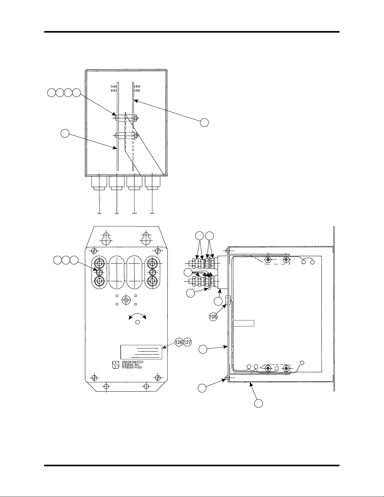
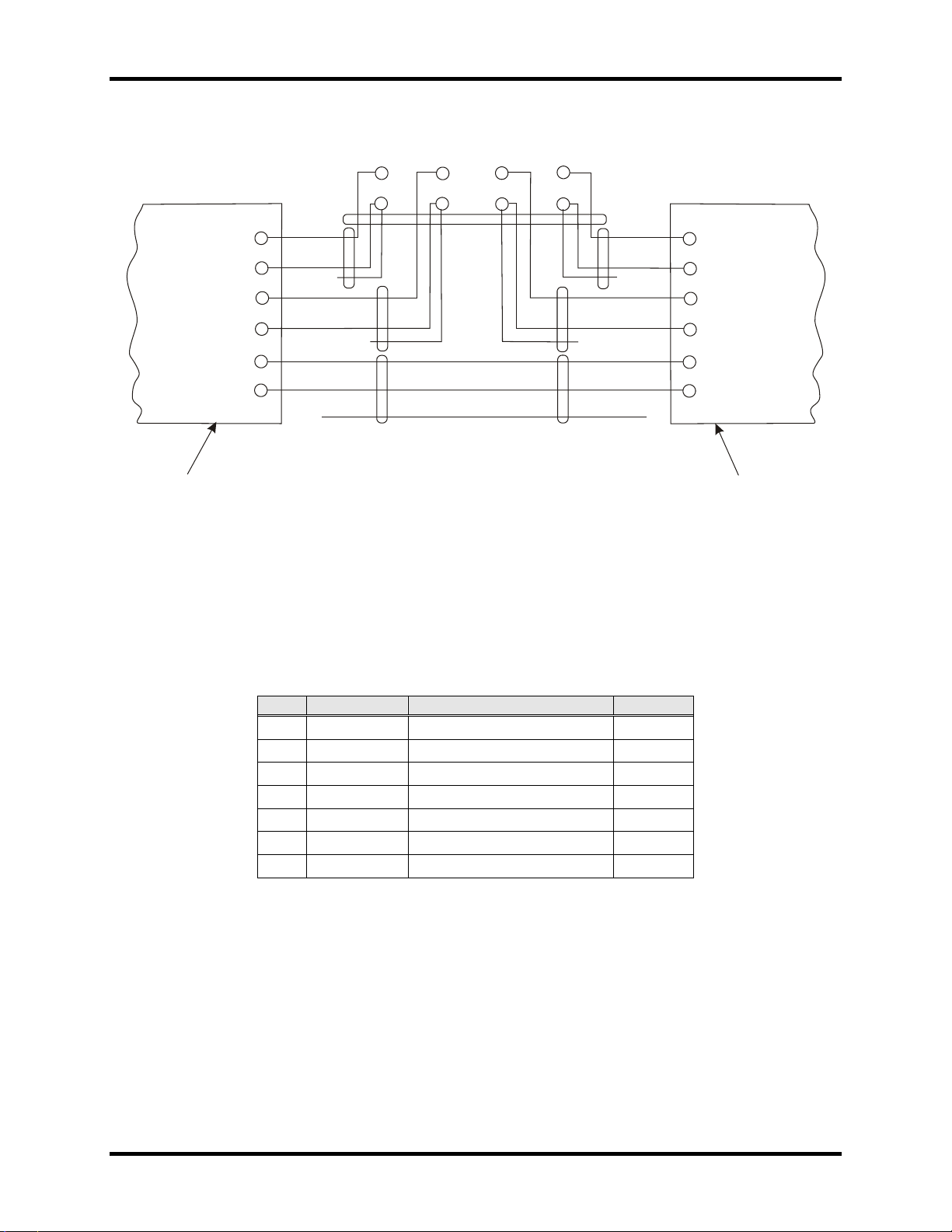
Table 6-4 and Table 6-5 contain parts lists for ATT-20 Audio Track Transceiver units
N451052-3901 through -3906. Refer to Figure 6-1 for the component locations. The
internal wring diagram is shown in Figure 6-2.
Table 6-4. ATT-20 Unit Parts List
5 Refer to Table 6-5 CHASSIS 1 EA
10 R438872 COVER 1 EA
15 Refer to Table 6-5 PCB,ATT-20 TRANSMITTER 1 EA
20 Refer to Table 6-5 PCB,ATT-20 RECEIVER 1 EA
25 M181829 4 WAY BLOCK 1 EA
30 J5252720110 SCREW-10-32X5/8 SST 2 EA
35 J047733 WASHER,10 STEEL LOCK MED 2 EA
40 J048172 NUT,10-32 HEX STEEL 2 EA
45 J047818 WASHER,17/64X9/16 COP 40 EA
50 J480300 NUT,14-24 HEX BRASS NP 16 EA
55 J480301 NUT,14-24 HEX BRASS 16 EA
60 J525111 SCREW,8-32X1-1/4 RD HD STEEL 4 EA
65 J047714 WASHER-8 SHPRF LK SS 4 EA
70 J048166 NUT,8-32 HEX STEEL 4 EA
75 M337854 INS TUBING 8 EA
80 J052686 SCREW,8X3/8 RD HD 4 EA
85 J730041 TERM-PRE-INSUL, DIAGR 8 EA
90 (not shown) J078399 BAG-PLASTIC,#60F-0406 1 EA
100 (not shown) S705.11 WIRE, TAG 12" BUNDLE 1 EA
105 J075415 GROMMET, RUBBER 3/8"ID 1 EA
110 (not shown) A774169 TUBING.HT SHRINK 3/16ID 1 FT
115 (not shown) A774184 TUBING SHRINK FIT 1/16 1 FT
120 (not shown) A434083 CA-1 TW. PR. SHELDD. MIN 6 FT
125 J703310 CABLE TIE, SELF LOCKING 5 EA
126 J0759550056 LABEL, WHITE, POLY, #M-787, OILTAK 1 EA
127 J7928220039 RIBBON, THERMAL TRANSFER, R6007 1 EA
Copyright 2019 SM 6299 Rev. 3, March 2019 6-2
Page 37

ATT-20 Audio Track Transceiver
CHASSIS
Item 5
XMITTER PCB
Item 15
RCVR PCB
Item 20
Table 6-5. ATT-20 Part Tabulation
ATT-20 Unit Freq. (KHz) Application
N451052-3901 12.28 Shunt R451053-6302 N451605-6402 N451605-6502
N451052-3902 15 Shunt R451053-6302 N451605-6403 N451605-6503
N451052-3903 20 Shunt R451053-6302 N451605-6404 N451605-6504
N451052-3904 12.28 Series R451053-6303 N451605-6405 N451605-6505
N451052-3905 15 Series R451053-6303 N451605-6406 N451605-6506
N451052-3906 20 Series R451053-6303 N451605-6407 N451605-6507
Copyright 2019 SM 6299 Rev. 3, March 2019 6-3
Page 38
ATT-20 Audio Track Transceiver
5
RCV
COMP. SIDE
2
AUDIO TRACK
TRANSCEIVER
MODEL,ATT-20
LOWER
+
RE LAY
-
TL5
COMP. SIDE
TL6
R14
SHUNT
MODE
UNIT
15
PC.NO.
SER.NO.
FREQ.
RE V.
4
5
8
7
40
+
BAT TERY
-
XMT
1
75
65
70
60
30
20
3
35
RELAY VOLTS
TL1
RAISE
6
10
80
TL2
TL3
TL4
25
85
45
55
50
3B3.0006.01
TL6
TL6
TL5
TL5
Copyright 2019 SM 6299 Rev. 3, March 2019 6-4
Figure 6-1. ATT-20 Parts Illustration
Page 39
ATT-20 Audio Track Transceiver
B
SHIELD
R
B-
B+
SHIELD
SHIELD
SHIELD
SHIELD
TL1
TL1
TL3
TL3
TL6
TL6
TL5
TL5
TL2
TL2
TL4
TL4
TRACK
TRACK
TRACK
TRACK
POWER
POWER
GND
GND
R
R
B
B
R
R
B
B
XMITER PCB
RCVR PCB
RE LAY +
RE LAY -
1
2
3
456
7
8
3B3.0007.00
Item
Part No.
Description
Quantity
Figure 6-2. ATT-20 Wiring Diagram
6.4. Cable Compensating PCB Parts List
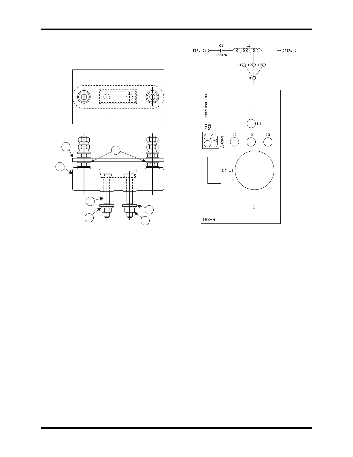
Refer to Table 6-6 and Figure 6-3 for Cable Compensating PCB, STS USA N13100201,
parts, parts layout, and schematic diagram.
Table 6-6. Cable Compensating PCB Parts List
5 N381621 BLOCK, TERM 1 EA
10 N13100101 PCB, CABLE COMPEN 1 EA
15 J047818 WASHER,17/64X9/16 COP 2 EA
20 J5000970128 SCR-SST 1/4-20X1-3/4 2 EA
25 J4751200112 WASHER, SST PLATE NO1/4 2 EA
30 J4751210111 WASHER, SST LOCK NO1/4 2 EA
35 J4802110108 NUT,1/4-20 SST HEX 2 EA
Copyright 2019 SM 6299 Rev. 3, March 2019 6-5
Page 40
ATT-20 Audio Track Transceiver
10
15
5
20
30
25
35
3B3.0008.00
Figure 6-3. Cable Compensating PCB Parts Layout and Schematic Diagram
Copyright 2019 SM 6299 Rev. 3, March 2019 6-6
Page 41

ATT-20 Audio Track Transceiver
7. RAIL TEAM AND TECHNICAL SUPPORT
The Rapid Action Information Link Team (RAIL Team) is a group of experienced
product and application engineers ready to assist you to resolve any technical issues
concerning this product. Contact the RAIL Team in the United States at 1-800-652-7276
or by e-mail at [email protected].
Copyright 2019 SM 6299 Rev. 3, March 2019 7-1
Page 42

ATT-20 Audio Track Transceiver
End of Manual
Copyright 2019 SM 6299 Rev. 3, March 2019 7-2
 Loading...