

Page 1
Hitachi AMS 2000 Family Copy-on-Write
SnapShot User Guide
F
AST
F
IND
L
INKS
Document organization
Release notes and readme
Getting help
Table of Contents
MK-97DF8124-26
Page 2

© 2008-2016 Hitachi, Ltd. All Rights Reserved.
No part of this publication may be reproduced or transmitted in any form or by any means, electronic or
mechanical, including photocopying and recording, or stored in a database or retrieval system for any
purpose without the express written permission of Hitachi, Ltd. and Hitachi Data Systems Corporation
(hereinafter referred to as “Hitachi”).
Hitachi, Ltd. and Hitachi Data Systems reserve the right to make changes to this document at any time
without notice and assume no responsibility for its use. Hitachi, Ltd. and Hitachi Data Systems products and
services can only be ordered under the terms and conditions of Hitachi Data Systems' applicable agreements.
All of the features described in this document may not be currently available. Refer to the most recent
product announcement or contact your local Hitachi Data Systems sales office for information on feature and
product availability.
Notice: Hitachi Data Systems products and services can be ordered only under the terms and conditions of
Hitachi Data Systems’ applicable agreements. The use of Hitachi Data Systems products is governed by the
terms of your agreements with Hitachi Data Systems.
Hitachi is a registered trademark of Hitachi, Ltd. in the United States and other countries. Hitachi Data
Systems is a registered trademark and service mark of Hitachi in the United States and other countries.
All other trademarks, service marks, and company names are properties of their respective owners.
Export authorization is required for the AMS 2000 Data At Rest Encryption
• Import/Use regulations may restrict export of the AMS2000 SED to certain countries
• China – AMS2000 is eligible for import but the License Key and SED may not be sent to China
• France – Import pending completion of registration formalities
• Hong Kong – Import pending completion of registration formalities
• Israel – Import pending completion of registration formalities
• Russia – Import pending completion of notification formalities
• Distribution Centers – IDC, EDC and ADC cleared for exports
ii
Hitachi AMS 2000 Family Copy-on-Write SnapShot User Guide
Page 3

Table of Contents
Preface . . . . . . . . . . . . . . . . . . . . . . . . . . . . . . . . . . . . . . . . . . . . . . . . ix
Intended audience . . . . . . . . . . . . . . . . . . . . . . . . . . . . . . . . . . . . . . . . . . . .x
Product version . . . . . . . . . . . . . . . . . . . . . . . . . . . . . . . . . . . . . . . . . . . . . .x
Release notes and readme . . . . . . . . . . . . . . . . . . . . . . . . . . . . . . . . . . . . . .x
Product Abbreviations. . . . . . . . . . . . . . . . . . . . . . . . . . . . . . . . . . . . . . . . . .x
Document revision level . . . . . . . . . . . . . . . . . . . . . . . . . . . . . . . . . . . . . . . xi
Changes in this revision . . . . . . . . . . . . . . . . . . . . . . . . . . . . . . . . . . . . . . . xii
Document organization . . . . . . . . . . . . . . . . . . . . . . . . . . . . . . . . . . . . . . . . xii
Document conventions . . . . . . . . . . . . . . . . . . . . . . . . . . . . . . . . . . . . . . . .xiii
Convention for storage capacity values. . . . . . . . . . . . . . . . . . . . . . . . . . . . .xiv
Related documentation . . . . . . . . . . . . . . . . . . . . . . . . . . . . . . . . . . . . . . . .xiv
Getting help. . . . . . . . . . . . . . . . . . . . . . . . . . . . . . . . . . . . . . . . . . . . . . . . xx
Comments . . . . . . . . . . . . . . . . . . . . . . . . . . . . . . . . . . . . . . . . . . . . . . . xx
1 SnapShot overview . . . . . . . . . . . . . . . . . . . . . . . . . . . . . . . . . . . . . 1-1
Copy-on-Write SnapShot software . . . . . . . . . . . . . . . . . . . . . . . . . . . . . . . 1-2
Hardware and software configuration. . . . . . . . . . . . . . . . . . . . . . . . . . . . . 1-2
How SnapShot works . . . . . . . . . . . . . . . . . . . . . . . . . . . . . . . . . . . . . . . . 1-3
Volume pairs — P-VOLs and V-VOLs . . . . . . . . . . . . . . . . . . . . . . . . . . . . 1-3
Data pools . . . . . . . . . . . . . . . . . . . . . . . . . . . . . . . . . . . . . . . . . . . . . . 1-4
Consistency group (CTG) . . . . . . . . . . . . . . . . . . . . . . . . . . . . . . . . . . . . 1-6
Differential Management LUs (DMLU) . . . . . . . . . . . . . . . . . . . . . . . . . . . 1-6
LU Ownership of P-VOLs and data pools . . . . . . . . . . . . . . . . . . . . . . . . . 1-6
Interfaces for performing SnapShot operations . . . . . . . . . . . . . . . . . . . . . . 1-8
Cascade connection of SnapShot with Simple DR. . . . . . . . . . . . . . . . . . . . . 1-9
Cascade connection of SnapShot with Simple DR P-VOL . . . . . . . . . . . . . 1-10
Cascade connection of SnapShot with Simple DR S-VOL . . . . . . . . . . . . . 1-11
V-VOLs number of SnapShot. . . . . . . . . . . . . . . . . . . . . . . . . . . . . . . . . 1-11
Cascade connection of SnapShot with TrueCopy . . . . . . . . . . . . . . . . . . . . 1-12
Cascade restrictions with SnapShot P-VOL . . . . . . . . . . . . . . . . . . . . . . . 1-12
LU shared with P-VOL on SnapShot and P-VOL on TrueCopy . . . . . . . . 1-13
Contents iii
Hitachi AMS 2000 Family Copy-on-Write SnapShot User Guide
Page 4

One LU used for P-VOL on SnapShot and S-VOL on TrueCopy. . . . . . . .1-13
V-VOLs number of SnapShot . . . . . . . . . . . . . . . . . . . . . . . . . . . . . . .1-14
Cascade restrictions with SnapShot V-VOL . . . . . . . . . . . . . . . . . . . . . . .1-14
Configuration restrictions on the Cascade of TrueCopy with SnapShot . . . .1-16
Cascade restrictions with SnapShot Data Pool . . . . . . . . . . . . . . . . . . . . .1-16
Cache memory reconfiguration cautions . . . . . . . . . . . . . . . . . . . . . . .1-16
Cascade connection of SnapShot with ShadowImage . . . . . . . . . . . . . . . . .1-19
Cascade connection with P-VOL of ShadowImage . . . . . . . . . . . . . . . . . .1-22
Restriction when performing restoration . . . . . . . . . . . . . . . . . . . . . . .1-22
Performance when cascading the P-VOL of SnapShot and ShadowImage1-22
Cascade restrictions with S-VOL of ShadowImage . . . . . . . . . . . . . . . . . .1-24
Pair Operation Restrictions when Cascading SnapShot with ShadowImage.1-27
. . . . . . . . . . . . . . . . . . . . . . . . . . . . . . . . . . . . . . . . . . . . . . . . . . . .1-29
Simultaneous Cascading Restrictions with ShadowImage P-VOL and S-VOL1-30
Cascade Restrictions of TrueCopy with ShadowImage and SnapShot. . . . .1-31
2 Planning and design. . . . . . . . . . . . . . . . . . . . . . . . . . . . . . . . . . . . .2-1
The plan and design workflow . . . . . . . . . . . . . . . . . . . . . . . . . . . . . . . . . .2-2
Assessing business needs. . . . . . . . . . . . . . . . . . . . . . . . . . . . . . . . . . . . . .2-2
Copy frequency . . . . . . . . . . . . . . . . . . . . . . . . . . . . . . . . . . . . . . . . . . .2-2
Selecting a reasonable time between Snapshots . . . . . . . . . . . . . . . . . .2-3
Establishing how long a copy is held (copy lifespan). . . . . . . . . . . . . . . . . .2-3
Lifespan based on backup requirements . . . . . . . . . . . . . . . . . . . . . . . .2-3
Lifespan based on business uses . . . . . . . . . . . . . . . . . . . . . . . . . . . . .2-4
Establishing the number of V-VOLs. . . . . . . . . . . . . . . . . . . . . . . . . . . . . .2-4
Establishing data pool size . . . . . . . . . . . . . . . . . . . . . . . . . . . . . . . . . . . . .2-5
Measuring workload data, sizing the data pool. . . . . . . . . . . . . . . . . . . . . .2-5
Rule-of-thumb calculation . . . . . . . . . . . . . . . . . . . . . . . . . . . . . . . . . .2-9
Requirements and recommendations for SnapShot Logical Units . . . . . . . . .2-10
RAID configuration for LUs assigned to SnapShot . . . . . . . . . . . . . . . . . .2-10
Operating system considerations . . . . . . . . . . . . . . . . . . . . . . . . . . . . . . .2-13
Identifying P-VOL and V-VOL LUs on Windows . . . . . . . . . . . . . . . . . . . .2-13
LU mapping . . . . . . . . . . . . . . . . . . . . . . . . . . . . . . . . . . . . . . . . . . . . .2-14
Cluster and path switching software. . . . . . . . . . . . . . . . . . . . . . . . . . . .2-14
Microsoft Cluster Server (MSCS). . . . . . . . . . . . . . . . . . . . . . . . . . . . . . .2-14
AIX . . . . . . . . . . . . . . . . . . . . . . . . . . . . . . . . . . . . . . . . . . . . . . . . . . .2-14
Veritas Volume Manager (VxVM) . . . . . . . . . . . . . . . . . . . . . . . . . . . . . .2-14
Windows 2000 . . . . . . . . . . . . . . . . . . . . . . . . . . . . . . . . . . . . . . . . . . .2-14
Windows Server and SnapShot configuration. . . . . . . . . . . . . . . . . . . . . .2-15
Linux and LVM configuration . . . . . . . . . . . . . . . . . . . . . . . . . . . . . . . . .2-16
Tru64 UNIX and SnapShot configuration. . . . . . . . . . . . . . . . . . . . . . . . .2-16
Concurrent use of Cache Partition Manager. . . . . . . . . . . . . . . . . . . . . . .2-16
VMWare and SnapShot configuration . . . . . . . . . . . . . . . . . . . . . . . . . . .2-16
Concurrent use of Dynamic Provisioning . . . . . . . . . . . . . . . . . . . . . . . . .2-18
iv Contents
Hitachi AMS 2000 Family Copy-on-Write SnapShot User Guide
Page 5

User data area of cache memory . . . . . . . . . . . . . . . . . . . . . . . . . . . . . .2-21
Windows 2000/Windows Server and Dynamic Disk. . . . . . . . . . . . . . . . . .2-27
Limitations of Dirty Data Flush Number . . . . . . . . . . . . . . . . . . . . . . . . . .2-28
Formatting the DMLU in the Event of a Drive Failure. . . . . . . . . . . . . . . . .2-28
Cascading SnapShot with TrueCopy. . . . . . . . . . . . . . . . . . . . . . . . . . . . . .2-29
Cascading SnapShot with TrueCopy Extended Distance . . . . . . . . . . . . . . . .2-30
Maximum supported capacity . . . . . . . . . . . . . . . . . . . . . . . . . . . . . . . . . .2-31
SnapShot and TCE capacity . . . . . . . . . . . . . . . . . . . . . . . . . . . . . . . . . .2-32
. . . . . . . . . . . . . . .Maximum Supported Capacity of P-VOL and Data Pool2-34
No SnapShot-TCE cascade configuration . . . . . . . . . . . . . . . . . . . . . . .2-35
SnapShot-TCE cascade configuration. . . . . . . . . . . . . . . . . . . . . . . . . .2-36
SnapShot, TCE, ShadowImage concurrent capacity . . . . . . . . . . . . . . . . .2-37
Cache limitations on Data and Data Pool volumes . . . . . . . . . . . . . . . . . .2-39
3 System requirements . . . . . . . . . . . . . . . . . . . . . . . . . . . . . . . . . . . .3-1
System requirements . . . . . . . . . . . . . . . . . . . . . . . . . . . . . . . . . . . . . . . . 3-2
Displaying the hardware revision number . . . . . . . . . . . . . . . . . . . . . . . . 3-3
Supported platforms. . . . . . . . . . . . . . . . . . . . . . . . . . . . . . . . . . . . . . . . . 3-4
4 Installing and enabling SnapShot . . . . . . . . . . . . . . . . . . . . . . . . .4-1
Important prerequisite information . . . . . . . . . . . . . . . . . . . . . . . . . . . . . . 4-2
Installing or uninstalling SnapShot. . . . . . . . . . . . . . . . . . . . . . . . . . . . . . . 4-2
Enabling or disabling SnapShot . . . . . . . . . . . . . . . . . . . . . . . . . . . . . . . . .4-11
5 Configuring SnapShot . . . . . . . . . . . . . . . . . . . . . . . . . . . . . . . . . . .5-1
Configuration workflow. . . . . . . . . . . . . . . . . . . . . . . . . . . . . . . . . . . . . . . 5-2
Setting up the data pool . . . . . . . . . . . . . . . . . . . . . . . . . . . . . . . . . . . . . . 5-2
Setting up the Virtual Volume (V-VOL) (manual method) . . . . . . . . . . . . . . . 5-4
Setting up the Differential Management LU (DMLU). . . . . . . . . . . . . . . . . . . 5-5
Setting up the command device. . . . . . . . . . . . . . . . . . . . . . . . . . . . . . . . . 5-6
Setting the LU ownership . . . . . . . . . . . . . . . . . . . . . . . . . . . . . . . . . . . . . 5-7
Setting the System Tuning Parameter . . . . . . . . . . . . . . . . . . . . . . . . . . . . 5-8
Cascade configuration of SnapShot and ShawdowImage . . . . . . . . . . . . . . . 5-9
Pair Resynchronization and Releasing. . . . . . . . . . . . . . . . . . . . . . . . . . . . .5-10
6 Using SnapShot . . . . . . . . . . . . . . . . . . . . . . . . . . . . . . . . . . . . . . . .6-1
SnapShot replication workflow. . . . . . . . . . . . . . . . . . . . . . . . . . . . . . . . . . 6-2
Back up your volume — creating a pair . . . . . . . . . . . . . . . . . . . . . . . . . . . 6-2
Creating a pair using the Backup Wizard . . . . . . . . . . . . . . . . . . . . . . . . . 6-2
Creating a pair using the Create Pair procedure . . . . . . . . . . . . . . . . . . . . 6-3
Updating the V-VOL . . . . . . . . . . . . . . . . . . . . . . . . . . . . . . . . . . . . . . . . . 6-5
Restoring the P-VOL from the V-VOL . . . . . . . . . . . . . . . . . . . . . . . . . . . . . 6-6
Use the V-VOL for tape backup, testing, reports, etc. . . . . . . . . . . . . . . . . . 6-7
Contents v
Hitachi AMS 2000 Family Copy-on-Write SnapShot User Guide
Page 6

Tape backup recommendations . . . . . . . . . . . . . . . . . . . . . . . . . . . . . . . .6-8
Restoring data from a tape backup. . . . . . . . . . . . . . . . . . . . . . . . . . . .6-9
Editing a pair, data pool. . . . . . . . . . . . . . . . . . . . . . . . . . . . . . . . . . . . . .6-10
Deleting pairs, V-VOLs, data pools, DMLU . . . . . . . . . . . . . . . . . . . . . . . . .6-10
7 Monitoring and maintenance. . . . . . . . . . . . . . . . . . . . . . . . . . . . . .7-1
Monitoring SnapShot . . . . . . . . . . . . . . . . . . . . . . . . . . . . . . . . . . . . . . . . .7-2
Monitoring pair status . . . . . . . . . . . . . . . . . . . . . . . . . . . . . . . . . . . . . . .7-2
Monitoring data pool usage . . . . . . . . . . . . . . . . . . . . . . . . . . . . . . . . . . .7-4
Expanding data pool capacity . . . . . . . . . . . . . . . . . . . . . . . . . . . . . . . . . . .7-4
Other methods for lowering data pool load . . . . . . . . . . . . . . . . . . . . . . . .7-4
8 Troubleshooting . . . . . . . . . . . . . . . . . . . . . . . . . . . . . . . . . . . . . . . .8-1
Pair failure . . . . . . . . . . . . . . . . . . . . . . . . . . . . . . . . . . . . . . . . . . . . . . . .8-2
Recovering from pair failure due to POOL FULL . . . . . . . . . . . . . . . . . . . . .8-2
Recovering from pair failure due to a hardware failure . . . . . . . . . . . . . . . .8-3
Data pool capacity exceeded . . . . . . . . . . . . . . . . . . . . . . . . . . . . . . . . . . .8-3
A Specifications. . . . . . . . . . . . . . . . . . . . . . . . . . . . . . . . . . . . . . . . . A-1
SnapShot specifications . . . . . . . . . . . . . . . . . . . . . . . . . . . . . . . . . . . . . . .A-2
B Operations using CLI. . . . . . . . . . . . . . . . . . . . . . . . . . . . . . . . . . . B-1
Installing and uninstalling SnapShot . . . . . . . . . . . . . . . . . . . . . . . . . . . . . .B-2
Important prerequisite information. . . . . . . . . . . . . . . . . . . . . . . . . . . . . .B-2
Installing SnapShot. . . . . . . . . . . . . . . . . . . . . . . . . . . . . . . . . . . . . . . . .B-2
Uninstalling SnapShot . . . . . . . . . . . . . . . . . . . . . . . . . . . . . . . . . . . . . . .B-6
Enabling or disabling SnapShot. . . . . . . . . . . . . . . . . . . . . . . . . . . . . . . . . .B-7
Operations for SnapShot configuration. . . . . . . . . . . . . . . . . . . . . . . . . . . .B-10
Setting the DMLU . . . . . . . . . . . . . . . . . . . . . . . . . . . . . . . . . . . . . . . . .B-10
Setting the POOL . . . . . . . . . . . . . . . . . . . . . . . . . . . . . . . . . . . . . . . . .B-11
Setting the V-VOL. . . . . . . . . . . . . . . . . . . . . . . . . . . . . . . . . . . . . . . . .B-13
Setting the LU ownership . . . . . . . . . . . . . . . . . . . . . . . . . . . . . . . . . . .B-13
Setting the System Tuning Parameter . . . . . . . . . . . . . . . . . . . . . . . . . . . .B-14
Performing SnapShot operations. . . . . . . . . . . . . . . . . . . . . . . . . . . . . . . .B-15
Creating SnapShot pairs using CLI . . . . . . . . . . . . . . . . . . . . . . . . . . . . .B-15
Updating SnapShot Logical Unit using CLI. . . . . . . . . . . . . . . . . . . . . . . .B-15
Restoring V-VOL to P-VOL using CLI. . . . . . . . . . . . . . . . . . . . . . . . . . . .B-16
Releasing SnapShot pairs using CLI . . . . . . . . . . . . . . . . . . . . . . . . . . . .B-17
Changing pair information using CLI. . . . . . . . . . . . . . . . . . . . . . . . . . . .B-17
Creating multiple SnapShot pairs that belong to a group using CLI . . . . . .B-18
Sample back up script for Windows. . . . . . . . . . . . . . . . . . . . . . . . . . . . . .B-19
vi Contents
Hitachi AMS 2000 Family Copy-on-Write SnapShot User Guide
Page 7

C Operations using CCI . . . . . . . . . . . . . . . . . . . . . . . . . . . . . . . . . . C-1
Setting up CCI. . . . . . . . . . . . . . . . . . . . . . . . . . . . . . . . . . . . . . . . . . . . . C-2
Setting the command device . . . . . . . . . . . . . . . . . . . . . . . . . . . . . . . . . C-2
Setting LU Mapping information . . . . . . . . . . . . . . . . . . . . . . . . . . . . . . . C-3
Defining the configuration definition file . . . . . . . . . . . . . . . . . . . . . . . . . C-4
Setting the environment variable . . . . . . . . . . . . . . . . . . . . . . . . . . . . . . C-8
Performing SnapShot operations . . . . . . . . . . . . . . . . . . . . . . . . . . . . . . . C-10
Confirming pair status . . . . . . . . . . . . . . . . . . . . . . . . . . . . . . . . . . . . . C-10
Paircreate operation . . . . . . . . . . . . . . . . . . . . . . . . . . . . . . . . . . . . . . C-11
Pair creation using a consistency group. . . . . . . . . . . . . . . . . . . . . . . C-12
Updating the V-VOL. . . . . . . . . . . . . . . . . . . . . . . . . . . . . . . . . . . . . . . C-12
Restoring a V-VOL to the P-VOL . . . . . . . . . . . . . . . . . . . . . . . . . . . . . . C-13
Releasing SnapShot pairs. . . . . . . . . . . . . . . . . . . . . . . . . . . . . . . . . . . C-13
Pair, group name differences in CCI and Navigator 2. . . . . . . . . . . . . . . . . C-14
D Using SnapShot with Cache Partition Manager . . . . . . . . . . . . . D-1
SnapShot with Cache Partition Manager . . . . . . . . . . . . . . . . . . . . . . . . . . . D-2
Glossary
Index
Contents vii
Hitachi AMS 2000 Family Copy-on-Write SnapShot User Guide
Page 8

viii Contents
Hitachi AMS 2000 Family Copy-on-Write SnapShot User Guide
Page 9

Preface
This document provides instructions on assessing your snapshot
requirements, designing an implementation to meet those
requirements, and implementing and operating Copy-on-Write
Snapshot software using the Storage Navigator 2 graphical user
interface.
This preface includes the following information:
Intended audience
Product version
Release notes and readme
Document revision level
Changes in this revision
Document organization
Document conventions
Convention for storage capacity values
Related documentation
Getting help
Preface ix
Hitachi AMS 2000 Family Copy-on-Write SnapShot User Guide
Page 10
Intended audience
This document is intended for system administrators, Hitachi Data Systems
representatives, and Authorized Service Providers who install, configure,
and operate Hitachi Adaptable Modular System (AMS) 2000 family storage
systems.
Product version
This document applies to Hitachi AMS 2000 Family firmware version
08D1/D or later.
Release notes and readme
Read the release notes and readme file before installing and using this
product. They may contain requirements or restrictions that are not fully
described in this document and updates or corrections to this document.
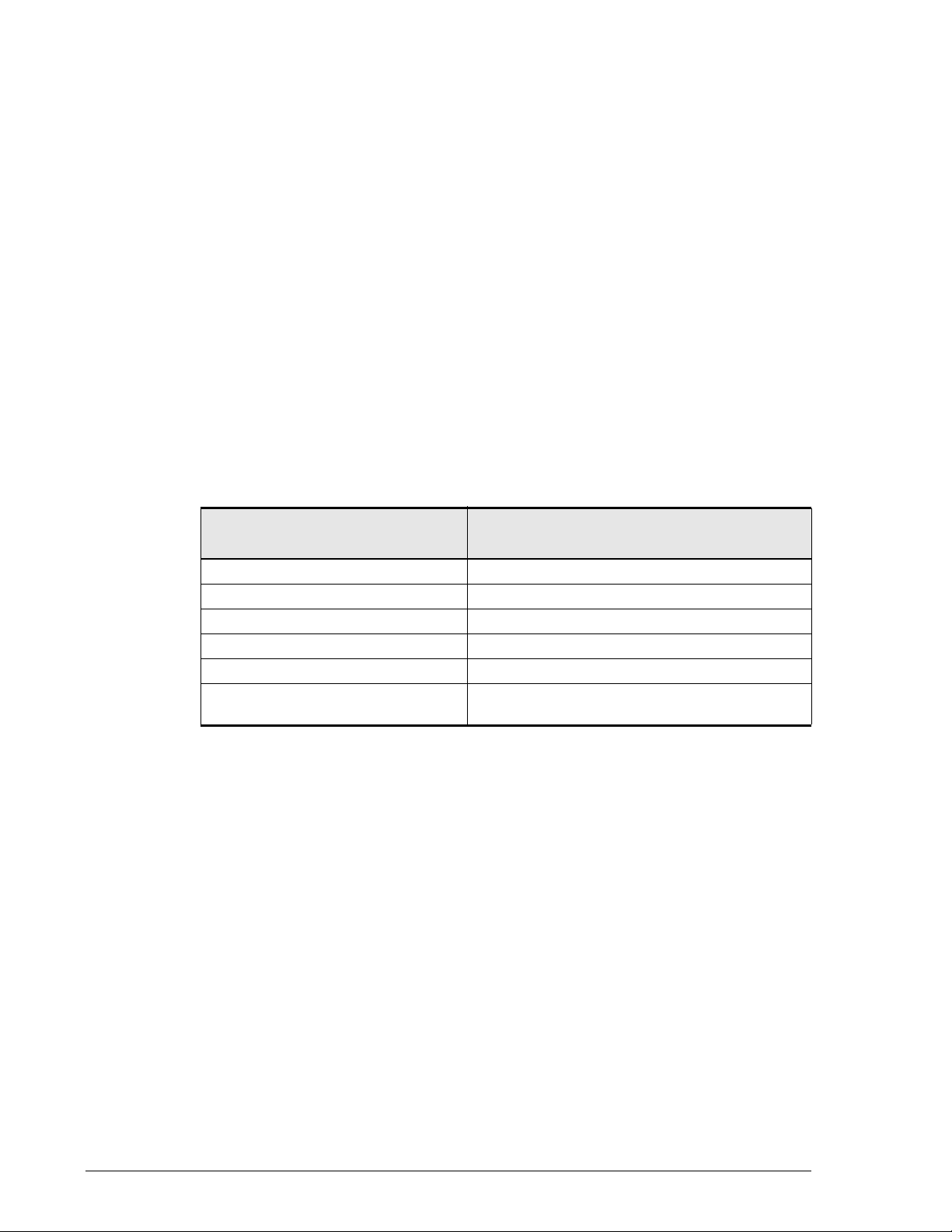
Product Abbreviations
Product Abbreviation
ShadowImage ShadowImage In-system Replication
Snapshot Copy-on-Write Snapshot
TrueCopy Remote TrueCopy Remote Replication
TCE TrueCopy Extended Distance
TCMD TrueCopy Modular Distributed
Windows Server Windows Server 2003, Windows Server 2008,
and Windows Server 2012.
Product Full Name
x Preface
Hitachi AMS 2000 Family Copy-on-Write SnapShot User Guide
Page 11
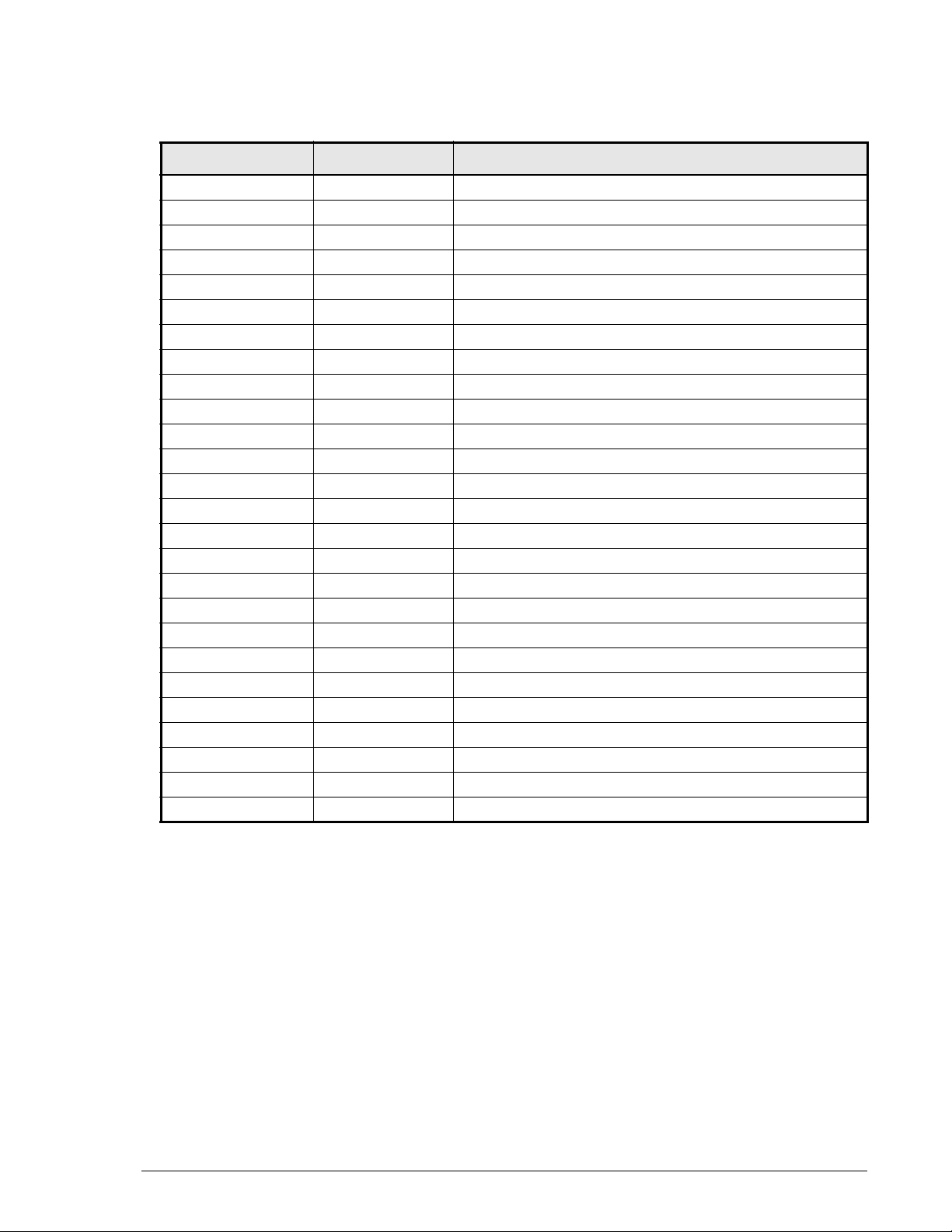
Document revision level
This section provides a history of the revision changes to this document.
Revision Date Description
MK-97DF8124-01 October 2008 Initial release.
MK-97DF8124-02 December 2008 Revision 02, supersedes and replaces MK-97DF8124-01.
MK-97DF8124-03 March 2009 Revision 03, supersedes and replaces MK-97DF8124-02.
MK-97DF8124-04 June 2009 Revision 04, supersedes and replaces MK-97DF8124-03.
MK-97DF8124-05 August 2009 Revision 05, supersedes and replaces MK-97DF8124-04.
MK-97DF8124-06 November 2009 Revision 06, supersedes and replaces MK-97DF8124-05.
MK-97DF8124-07 January 2010 Revision 07, supersedes and replaces MK-97DF8124-06.
MK-97DF8124-08 April 2010 Revision 08, supersedes and replaces MK-97DF8124-07.
MK-97DF8124-09 August 2010 Revision 09, supersedes and replaces MK-97DF8124-08.
MK-97DF8124-10 September 2010 Revision 10, supersedes and replaces MK-97DF8124-09.
MK-97DF8124-11 November 2010 Revision 11, supersedes and replaces MK-97DF8124-10.
MK-97DF8124-12 December 2010 Revision 12, supersedes and replaces MK-97DF8124-11.
MK-97DF8124-13 February 2011 Revision 13, supersedes and replaces MK-97DF8124-12.
MK-97DF8124-14 May 2011 Revision 14, supersedes and replaces MK-97DF8124-13.
MK-97DF8124-15 July 2011 Revision 15 supersedes and replaces MK-97DF8124-14.
MK-97DF8124-16 August 2011 Revision 16 supersedes and replaces MK-97DF8124-15.
MK-97DF8124-17 September 2011 Revision 17 supersedes and replaces MK-97DF8124-16.
MK-97DF8124-18 March 2012 Revision 18 supersedes and replaces MK-97DF8124-17.
MK-97DF8124-19 June 2012 Revision 19 supersedes and replaces MK-97DF8124-18.
MK-97DF8124-20 December 2012 Revision 20 supersedes and replaces MK-97DF8124-19.
MK-97DF8124-21 January 2013 Revision 21 supersedes and replaces MK-97DF8124-20.
MK-97DF8124-22 May 2013 Revision 22 supersedes and replaces MK-97DF8124-21.
MK-97DF8124-23 July 2013 Revision 23 supersedes and replaces MK-97DF8124-22.
MK-97DF8124-24 December 2013 Revision 24 supersedes and replaces MK-97DF8124-23.
MK-97DF8124-25 January 2015 Revision 25 supersedes and replaces MK-97DF8124-24.
MK-97DF8124-26 January 2016 Revision 26 supersedes and replaces MK-97DF8124-25.
Preface xi
Hitachi AMS 2000 Family Copy-on-Write SnapShot User Guide
Page 12
Changes in this revision
The following information has been added for this release:
•Under Creating a pair using the Create Pair procedure on page 6-3,
added the note after step 5.
•Under Creating SnapShot pairs using CLI on page B-15 and Paircreate
operation on page C-11, added the note preceding the procedure.
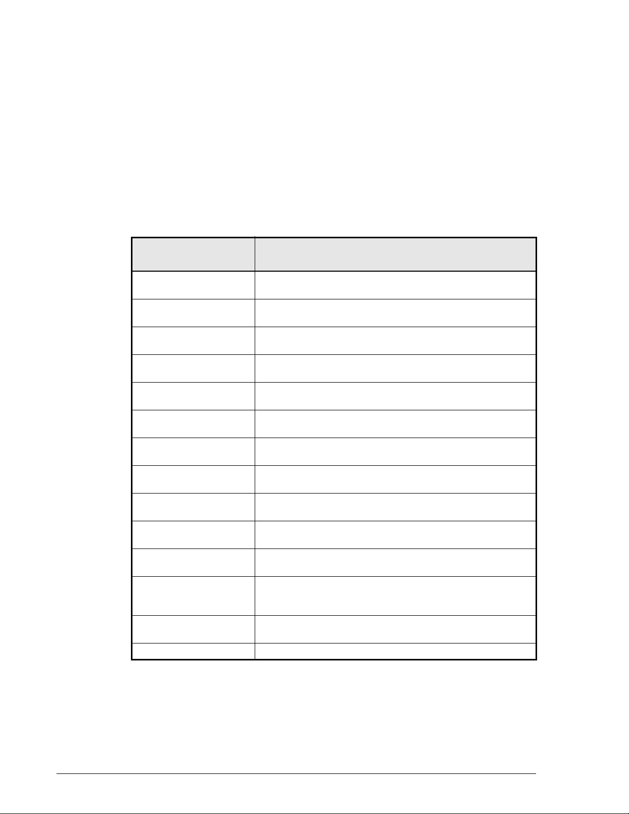
Document organization
Thumbnail descriptions of the chapters are provided in the following table.
Click the chapter title in the first column to go to that chapter. The first page
of every chapter or appendix contains links to the contents.
Chapter/Appendix
Title
Chapter 1, SnapShot
overview
Chapter 2, Planning and
design
Chapter 3, System
requirements
Chapter 4, Installing and
enabling SnapShot
Chapter 5, Configuring
SnapShot
Chapter 6, Using
SnapShot
Chapter 7, Monitoring
and maintenance
Chapter 8,
Troubleshooting
Appendix A,
Specifications
Appendix B, Operations
using CLI
Appendix C, Operations
using CCI
Appendix D, Using
SnapShot with Cache
Partition Manager
Glossary Provides definitions for terms and acronyms found in this
Index Provides locations to specific information in this document.
Provides descriptions of SnapShot components and how
they work together.
Provides detailed planning and design information.
Provides SnapShot requirements.
Provides instructions for installing SnapShot.
Provides configuration information.
Provides information and procedures for using SnapShot.
Provides monitoring and maintenance information.
Provides information for correcting system problems.
Provides SnapShot specifications.
Provides Navigator 2 Command Line Interface instructions
for configuring and using SnapShot.
Provides detailed Command Control Interface instructions
for configuring and using SnapShot.
Provides information for using SnapShot with Cache
Partition Manager.
document.
Description
xii Preface
Hitachi AMS 2000 Family Copy-on-Write SnapShot User Guide
Page 13
Document conventions
This document uses the following symbols to draw attention to important
safety and operational information.
Symbol Meaning Description
Tip Tips provide helpful information, guidelines, or suggestions for
Note Notes emphasize or supplement important points of the main
Caution Cautions indicate that failure to take a specified action could
The following typographic conventions are used in this document.
Convention Description
Bold Indicates text on a window, other than the window title, including
menus, menu options, buttons, fields, and labels. Example: Click
OK.
Italic Indicates a variable, which is a placeholder for actual text provided
by the user or system. Example: copy source-file target-file. Note:
Angled brackets (< >) are also used to indicate variables.
screen/code
< > angled
brackets
[ ] square
brackets
{ } braces
| vertical bar Indicates that you have a choice between two or more options or
underline Indicates the default value. Example: [ a
Indicates text that is displayed on screen or entered by the user.
Example: # pairdisplay -g oradb
Indicates a variable, which is a placeholder for actual text provided
by the user or system. Example: # pairdisplay -g <group>
Note: Italic font is also used to indicate variables.
Indicates optional values. Example: [ a | b ] indicates that you can
choose a, b, or nothing.
Indicates required or expected values. Example: { a | b } indicates
that you must choose either a or b.
arguments. Examples:
[ a | b ] indicates that you can choose a, b, or nothing.
{ a | b } indicates that you must choose either a or b.
performing tasks more effectively.
text.
result in damage to the software or hardware.
| b ]
Preface xiii
Hitachi AMS 2000 Family Copy-on-Write SnapShot User Guide
Page 14
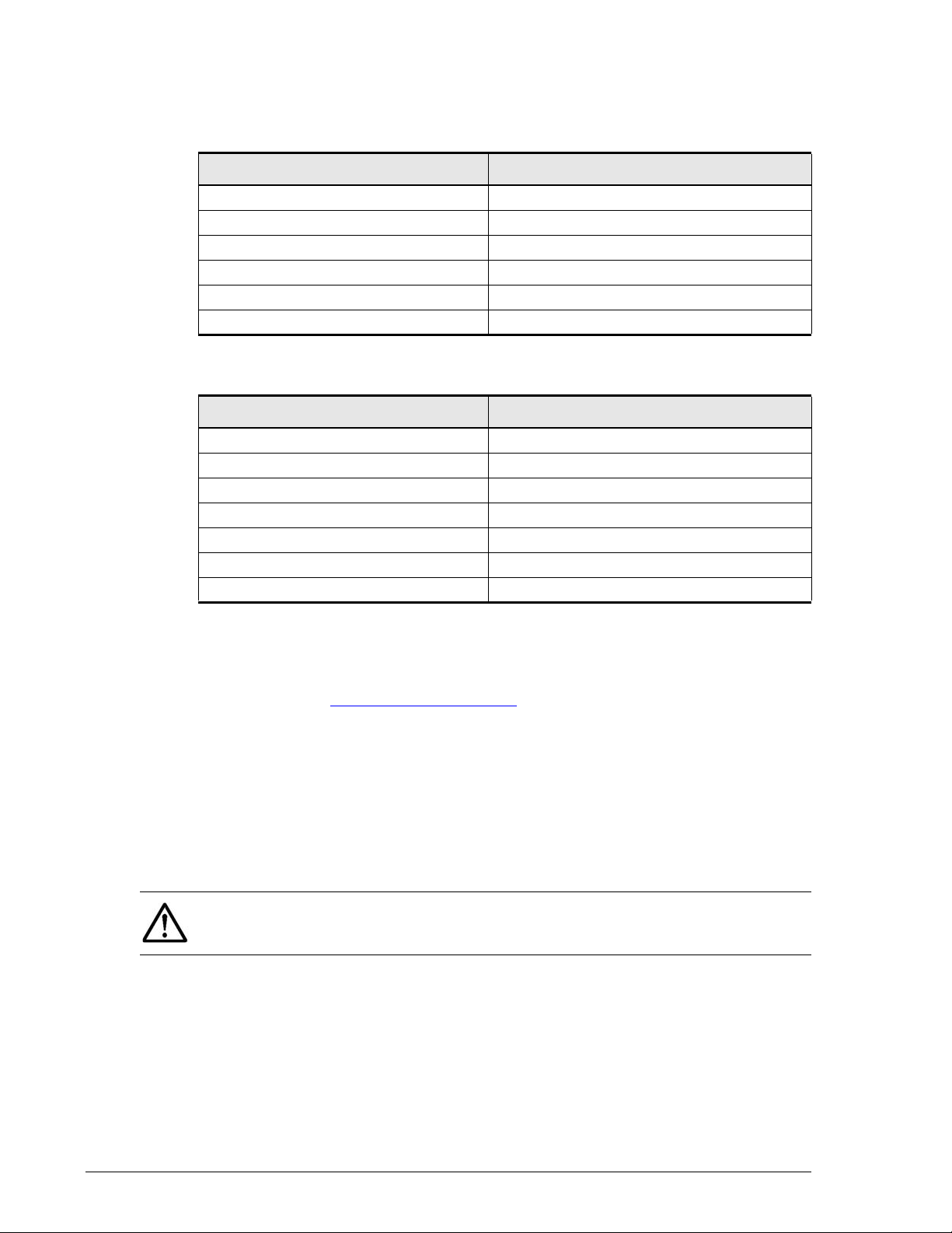
Convention for storage capacity values
Physical storage capacity values (e.g., disk drive capacity) are calculated
based on the following values:
Physical capacity unit Value
1 KB 1,000 bytes
1 MB 1,000 KB or 1,000
1 GB 1,000 MB or 1,0003 bytes
1 TB 1,000 GB or 1,0004 bytes
1 PB 1,000 TB or 1,0005 bytes
1 EB 1,000 PB or 1,000
Logical storage capacity values (e.g. , logical device capacity) are calculated
based on the following values:
Logical capacity unit Value
1 block 512 bytes
1 KB 1,024 (210) bytes
1 MB 1,024 KB or 1024
1 GB 1,024 MB or 10243 bytes
1 TB 1,024 GB or 10244 bytes
1 PB 1,024 TB or 1024
1 EB 1,024 PB or 10246 bytes
2
bytes
6
bytes
2
bytes
5
bytes
Related documentation
The AMS 2000 Family user documentation is available on the Hitachi Data
Systems Portal: https://portal.hds.com
current documentation, including important updates that may have been
made after the release of the product.
This documentation set consists of the following documents.
Release notes
• Adaptable Modular Storage System Release Notes
• Storage Navigator Modular 2 Release Notes
Please read the release notes before installing and using this product. They
may contain requirements and restrictions not fully described in this
document, along with updates and corrections to this document.
. Please check this site for the most
xiv Preface
Hitachi AMS 2000 Family Copy-on-Write SnapShot User Guide
Page 15

Installation and getting started
The following documents provide instructions for installing an AMS 2000
Family stor age system. They include rack information, safety information,
site-preparation instructions, getting-started guides for experienced users,
and host connectivity information. The symbol
contain initial configuration information about Hitachi AMS 2000 Family
storage systems.
AMS2100/2300 Getting Started Guide, MK-98DF8152
?
Provides quick-start instructions for getting an AMS 2100 or AMS 2300
storage system up and running as quickly as possible.
AMS2500 Getting Started Guide, MK-97DF8032
?
Provides quick-start instructions for getting an AMS 2500 storage
system up and running as quickly as possible.
AMS 2000 Family Site Preparation Guide, MK-98DF8149
Contains site planning and pre-installation information for AMS 2000
Family stor age systems, expansion units, and high-density expansion
units. This document also covers safety precautions, rack information,
and product specifications.
identifies documents that
?
AMS 2000 Family Fibre Channel Host Installation Guide,
MK-08DF8189
Describes how to prepare Hitachi AMS 2000 Family Fibre Channel
storage systems for use with host servers running supported operating
systems.
AMS 2000 Family iSCSI Host Installation Guide, MK-08DF8188
Describes how to prepare Hitachi AMS 2000 Family iSCSI storage
systems for use with host servers running supported operating systems.
Storage and replication features
The following documents describe how to use Storage Navigator Modular 2
(Navigator 2) to perform storage and replication activities.
Storage Navigator 2 Advanced Settings User’s Guide, MK-97DF8039
Contains advanced information about launching and using Navigator 2
in various operating systems, IP addresses and port numbers, server
certificates and private keys, boot and restore options, outputting
configuration information to a file, and collecting diagnostic information.
Preface xv
Hitachi AMS 2000 Family Copy-on-Write SnapShot User Guide
Page 16

Storage Navigator Modular 2 User’s Guide, MK-99DF8208
Describes how to use Navigator 2 to configure and manage storage on
an AMS 2000 Family storage system.
AMS 2000 Family Dynamic Provisioning Configuration Guide,
MK-09DF8201
Describes how to use virtual storage capabilities to simplify storage
additions and administration.
Storage Navigator 2 Storage Features Reference Guide for AMS,
MK-97DF8148
Contains concepts, preparation, and specifications for Account
Authentication, Audit Logging, Cache Partition Manager, Cache
Residency Manager, Data Retention Utility, LUN Manager, Performance
Monitor, SNMP Agent, and Modular Volume Migration.
AMS 2000 Family Copy-on-write SnapShot User Guide,
MK-97DF8124 — this document
Describes how to create point-in-time copies of data volumes in AMS
2100, AMS 2300, and AMS 2500 storage systems, without impacting
host service and performance levels. Snapshot copies are fully read/
write compatible with other hosts and can be used for rapid data
restores, application testing and development, data mining and
warehousing, and nondisruptive backup and maintenance procedures.
AMS 2000 Family ShadowImage In-system Replication User Guide,
MK-97DF8129
Describes how to perform high-speed nondisruptive local mirroring to
create a copy of mission-critical data in AMS 2100, AMS 2300, and AMS
2500 storage systems. ShadowImage keeps data RAID-protected and
fully recoverable, without affecting service or performance levels.
Replicated data volumes can be split from host applications and used for
system backups, application testing, and data mining applications while
business continues to operate at full capacity.
AMS 2000 Family TrueCopy Remote Replication User Guide,
MK-97DF8052
Describes how to create and maintain multiple duplicate copies of user
data across multiple AMS 2000 Family storage systems to enhance your
disaster recovery strategy.
AMS 2000 Family TrueCopy Extended Distance User Guide,
MK-97DF8054
Describes how to perform bi-directional remote data protection that
copies data over any distance without interrupting applications, and
provides failover and recovery capabilities.
xvi Preface
Hitachi AMS 2000 Family Copy-on-Write SnapShot User Guide
Page 17

AMS 2000 Data Retention Utility User’s Guide, MK-97DF8019
Describes how to lock disk volumes as read-only for a certain period of
time to ensure authorized-only access and facilitate immutable, tamperproof record retention for storage-compliant environments. After data is
written, it can be retrieved and read only by authorized applications or
users, and cannot be changed or deleted during the specified retention
period.
Storage Navigator Modular 2 online help
Provides topic and context-sensitive help information accessed through
the Navigator 2 software.
Hardware maintenance and operation
The following documents describe how to operate, maintain, and administer
an AMS 2000 Family storage system. They also provide a wide range of
technical information and specifications for the AMS 2000 Family storage
systems. The symbol
information about Hitachi AMS 2000 Family storage systems.
AMS 2100/2300 Storage System Hardware Guide, MK-97DF801 0
?
Provides detailed information about installing, configuring, and
maintaining an AMS 2100/2300 storage system.
identifies documents that contain initial configuration
?
AMS 2500 Storage System Hardware Guide, MK-97DF8007
?
Provides detailed information about installing, configuring, and
maintaining an AMS 2500 storage system.
AMS 2000 Family Storage System Reference Guide,
?
MK-97DF8008
Contains specifications and technical information about power cables,
system parameters, interfaces, logical blocks, RAID levels and
configurations, and regulatory information about AMS 2100, AMS 2300,
and AMS 2500 storage systems. This document also contains remote
adapter specifications and regulatory information.
AMS 2000 Family Storage System Service and Upgrade Guide,
MK-97DF8009
Provides information about servicing and upgrading AMS 2100, AMS
2300, and AMS 2500 storage systems.
AMS 2000 Family Power Savings User Guide, MK-97DF8045
Describes how to spin down volumes in selected RAID groups when they
are not being accessed by business applications to decrease energy
consumption and significantly reduce the cost of storing and delivering
information.
Preface xvii
Hitachi AMS 2000 Family Copy-on-Write SnapShot User Guide
Page 18

Command and Control (CCI)
The following documents describe how to install the Hitachi AMS 2000
Family Command Control Interface (CCI) and use it to perform TrueCopy
and ShadowImage operations.
AMS 2000 Family Command Control Interface (CCI) Installation
Guide, MK-97DF8122
Describes how to install CCI software on open-system hosts.
AMS 2000 Family Command Control Interface (CCI) Reference
Guide, MK-97DF8121
Contains reference, troubleshooting, and maintenance information
related to CCI operations on AMS 2100, AMS 2300, and AMS 2500
storage systems.
AMS 2000 Family Command Control Interface (CCI) User’s Guide,
MK-97DF8123
Describes how to use CCI to perform TrueCopy and ShadowImage
operations on AMS 2100, AMS 2300, and AMS 2500 storage systems.
Command Line Interface (CLI)
The following documents describe how to use Hitachi Storage Navigator
Modular 2 to perform management and replication activities from a
command line.
Storage Navigator Modular 2 Command Line Interface (CLI) Unified
Reference Guide, MK-97DF8089
Describes how to interact with all Navigator 2 bundled and optional
software modules by typing commands at a command line.
Storage Navigator 2 Command Line Interface Replication Reference
Guide for AMS, MK -97DF8153
Describes how to interact with Navigator 2 to perform replication
activities by typing commands at a command line.
xviii Preface
Hitachi AMS 2000 Family Copy-on-Write SnapShot User Guide
Page 19

Dynamic Replicator documentation
The following documents describe how to install, configure, and use Hitachi
Dynamic Replicator to provide AMS F amily storage systems with continuous
data protection, remote replication, and application failover in a single,
easy-to-deploy and manage platform.
Hitachi Dynamic Replicator - Scout Release Notes, RN-99DF8211
Hitachi Dynamic Replicator - Scout Host Upgrade Guide,
MK-99DF8267
Hitachi Dynamic Replicator - Scout Host User Guide,
MK-99DF8266
Hitachi Dynamic Replicator - Scout Installation and Configuration
Guide, MK-98DF8213
Hitachi Dynamic Replicator - Scout Quick Install/Upgrade Guide,
MK-98DF8222
Preface xix
Hitachi AMS 2000 Family Copy-on-Write SnapShot User Guide
Page 20

Getting help
If you need to contact the Hitachi Data Systems support center, please
provide as much information about the problem as possible, including:
• The circumstances surrounding the error or failure.
• The exact content of any messages displayed on the host systems.
• The exact content of any messages displayed on Storage Navigator
Modular 2.
• The Storage Navigator Modular 2 configuration information. This
information is used by service personnel for troubleshooting purposes.
The Hitachi Data Systems customer support staff is available 24 hours a
day , seven da ys a week. If you need technical support, please log on to the
Hitachi Data Systems Portal for contact information: https://portal.hds.com
Comments
Please send us your comments on this document to
doc.comments@hds.com
and refer to specific sections and paragraphs whenever possible.
Thank you! (All comments become the property of Hitachi Data Systems.)
. Include the document title, number , and revision,
xx Preface
Hitachi AMS 2000 Family Copy-on-Write SnapShot User Guide
Page 21

1
SnapShot overview
Copy-on-Write SnapShot creates virtual copies of data volumes
within the Hitachi Adaptable Modular Storage (AMS) array. These
copies can be used for recovery from logical errors. They are
identical to the original volume at the point in time they were
taken.
This guide provides instructions for planning and designing,
configuring and testing, and using and monitoring SnapShot. In
this chapter, see the following:
Copy-on-Write SnapShot software
Hardware and software configuration
How SnapShot works
Interfaces for performing SnapShot operations
Cascade connection of SnapShot with Simple DR
Cascade connection of SnapShot with ShadowImage
NOTE: “SnapShot” refers to Copy-on-Write SnapShot software. A
“snapshot” refers to a copy of the primary volume (P-VOL).
SnapShot overview 1–1
Hitachi AMS 2000 Family Copy-on-Write SnapShot User Guide
Page 22

Copy-on-Write SnapShot software
Hitachi’s Copy-on-Write Snapshot software creates virtual backup
copies of any data volume within the AMS array with minimal impact
to host service or performance levels. These snapshots are suitable
for immediate use in decision support, software testing and
development, data backup, or rapid recovery operations.
SnapShot minimizes disruption of planned or unplanned outages for
any application that cannot tolerate downtime for any reason or that
requires non-disruptive sharing of data. Since each snapshot
captures only the changes to the original data volume, the amount
of storage space required for each Copy-on-Write Snapshot is
significantly smaller than the original data volume.
The most probable types of target applications for Copy-on-Write
Snapshot are:
• Database copies for decision support/database inquiries
• Non-disruptive backups from a Snapshot secondary volume
• Periodic point-in-time disk copies for rapid restores in the event
of a corrupted data volume
Hardware and software configuration
A typical SnapShot hardware configur ation includes an AMS arr ay, a
host connected to the storage system, and management software to
configure and manage SnapShot. The host is connected to the
storage system using fibre channel or iSCSI connections. The
management software is connected to the storage system via a
management LAN.
SnapShot volumes include primary data volumes (P-VOLs) belonging
to the same consistency group, secondary volumes referred to as
virtual volumes (V-VOLs), data pool, a differential management
logical unit (DMLU), and command device. These elements are
explained in this chapter.
The SnapShot system is operated using Hitachi Storage Navigator
Modular 2 (Navigator 2) graphical user interface (GUI), Navigator 2
Command-Line interface (CLI), and Hitachi Command Control
Interface (CCI).
Figure 1-1 shows the SnapShot configuration.
1-2 SnapShot overview
Hitachi AMS 2000 Family Copy-on-Write SnapShot User Guide
Page 23
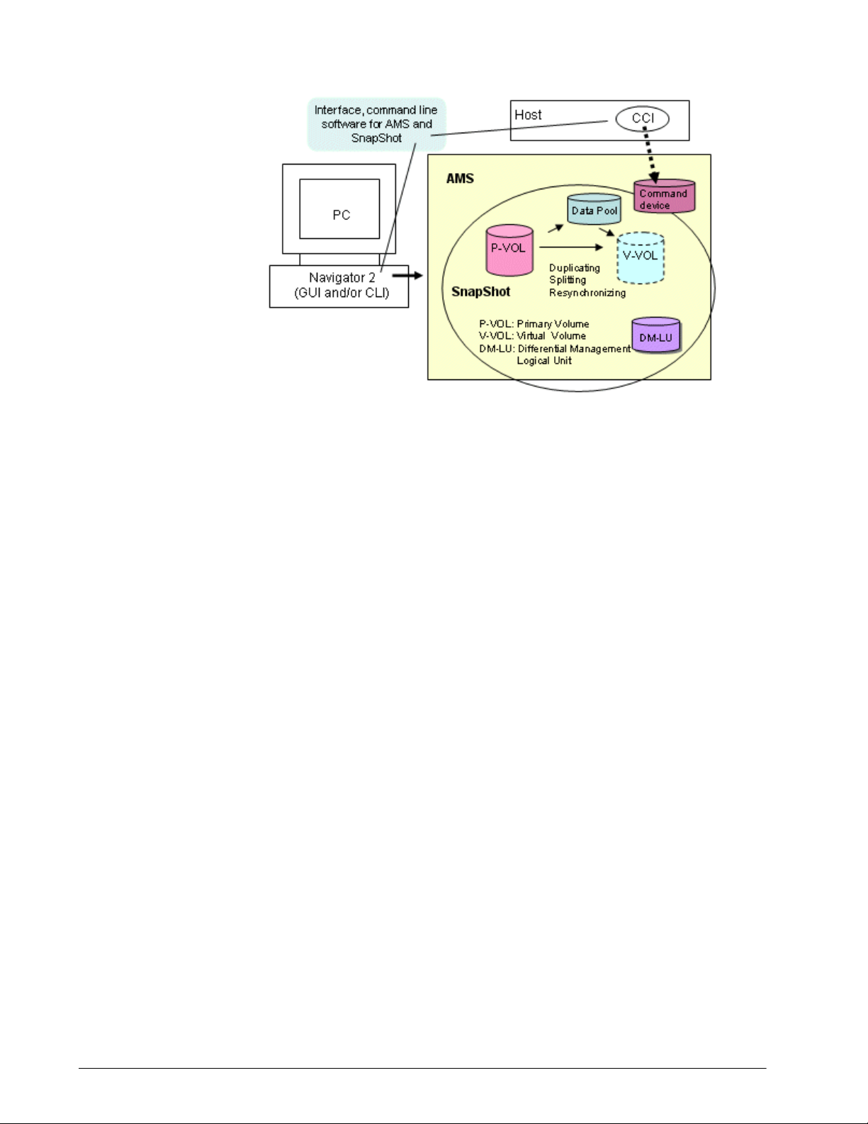
•
•
•
Figure 1-1: SnapShot functional component
The following sections describe how these components work
together.
How SnapShot works
SnapShot creates a virtual duplicate volume of another volume. This
volume “pair” is created when you:
• Select a volume that you want to replicate
• Identify another volume that will contain the copy
• Associate the primary and secondary volumes
• Create a snapshot of primary volume data in the virtual
(secondary) volume.
Once a snapshot is made, it remains unchanged until a new snapshot
instruction is issued. At that time, the new image replaces the
previous image.
Volume pairs — P-VOLs and V-VOLs
A volume pair is a relationship established by SnapShot between two
volumes. A pair consists of a production volume, which contains the
original data and is called the primary volume (P-VOL), and from 1
to 32 virtual volumes (V-VO Ls), which contain virtual copies of the PVOL. The P-VOL and its V-VOL(s) are located in the same array.
SnapShot overview 1-3
Hitachi AMS 2000 Family Copy-on-Write SnapShot User Guide
Page 24

Data pools
To maintain the snapshot image of the P-VOL when new data is
written to the P-VOL, SnapShot copies data that is being replaced to
the data pool. V-VOL pointers in cache memory are updated to
reference the original data's new location in the data pool. Figure 1-
2 illustrates SnapShot volumes and data pool interaction.
A V-VOL provides a virtual image of the P-VOL at the time of the
snapshot. Unlike the P-VOL, which contains actual data, the V -VOL is
made up of pointers to the data in the P-VOL, and to original data
that has been changed in the P-VOL since the last snapshot and
which has been copied to the data pool.
V-VOL’s are set up with LUs that are the same size as the related PVOL. This capacity is not actually used and remains available as free
storage capacity. This V-VOL sizing requirement (must be equal to
the P-VOL), is necessary for SnapShot and array logic. Also,
V-VOL pointers to data in the data pool and P- VOL actually reside in
cache memory . Because of this, part of your array’s cache is reserved
for SnapShot when it is enabled. (See Maximum supported capacity
on page 2-31 and Appendix D, Using SnapShot with Cache Partition
Manager.)
The data pool holds data from the P-VOL that is being replaced.
After a snapshot is taken, the V-VOL maintains pointers to P-VOL
data. If changes occur, before the updated block is written to the PVOL, the data that is being replaced is first copied to the data pool.
The V-VOL pointer to this block is updated to the new address in the
data pool. Thus, the V-VOL maintains the point-in-time image of the
P-VOL, until the next snapshot is taken.
A data pool can be shared by multiple SnapShot pairs.
The data pool’s function in the SnapShot process is illustrated in
Figure 1-2.
1-4 SnapShot overview
Hitachi AMS 2000 Family Copy-on-Write SnapShot User Guide
Page 25
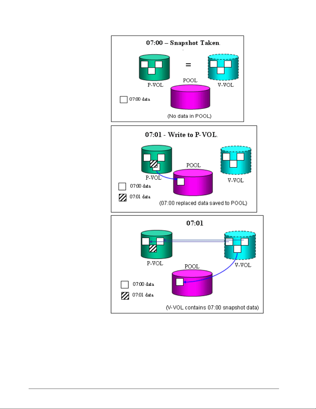
•
Figure 1-2: V-VOL Maintains SnapShot Data
SnapShot overview 1-5
Hitachi AMS 2000 Family Copy-on-Write SnapShot User Guide
Page 26

Consistency group (CTG)
Application data often spans more than one volume. With SnapShot,
it is possible to manage operations spanning multiple volumes as a
single group. In a “consistency group” (CTG), all primary logical
volumes are treated as a single entity.
Managing SnapShot primary volumes as a consistency group allows
multiple operations to be performed on grouped volumes
concurrently. Write order is guaranteed across application logical
volumes, since snapshots can be taken at the same time.
Differential Management LUs (DMLU)
The DMLU is an exclusive volume used for storing SnapShot
information when the array system is powered down. The DMLU is
treated the same as other volumes in the storage system, but is
hidden from a host. The DMLU requires user setup. See Setting up
the Differential Management LU (DMLU) on page 5-5 for details.
LU Ownership of P-VOLs and data pools
The load balancing function is not applied to the LUs specified as a
SnapShot pair.
The ownership of the LU specified in the S-VOl of the SnapShot pair
is the same as the ownership of the LU specified in the data pool. This
ownership change operates regardless of the setting status of load
balancing.
For example, if creating a SnapShot pair by specifying the LU whose
ownership is controller 0 as a P-VOL and assigned the LU whose
ownership is controller 1 as a data pool, the ownership of the LU
specified in the P-VOL is changed to controller 1.
If two or more SnapShot pairs share the same data pool, the
ownerships of all the pairs are biased toward the same controller and
the load is concentrated. To diversify the load, create two or more
data pools whose ownerships differ, and specify the data pool to be
equal when creating a SnapShot pair.
1-6 SnapShot overview
Hitachi AMS 2000 Family Copy-on-Write SnapShot User Guide
Page 27
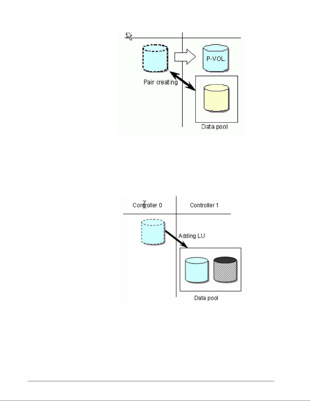
Figure 1-3: LU ownership
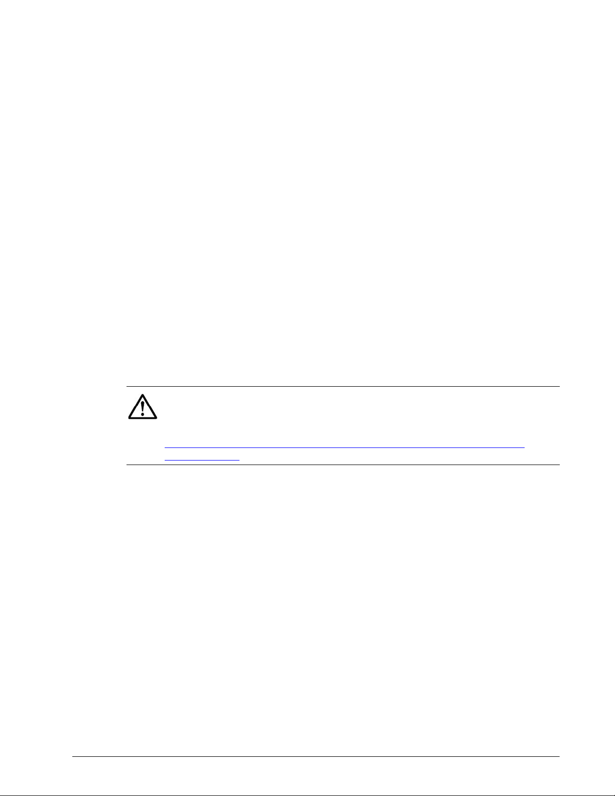
Furthermore, when adding LUs to increase the data pool capacity, if
the ownership of the LU already allocated to the data pool and the
ownership of the LU to be added have different controllers, the
ownership of the LU to be added is changed to the ownership of the
already allocated LU.
Figure 1-4: Adding LUs
If the ownership of a volume has been changed at pair creation, the
ownership is not changed at pair deletion. After deleting a pair, set
ownership again considering load balance.
Refer to Setting the LU ownership on page 5-7 or , for CLI, Setting the
LU ownership on page B-13 for more information.
SnapShot overview 1-7
Hitachi AMS 2000 Family Copy-on-Write SnapShot User Guide
Page 28
Interfaces for performing SnapShot operations
SnapShot can be operated using of the following interfaces:
• Navigator 2 GUI (Hitachi Storage Navigator Modular 2 Graphical
User Interface) is a browser-based interface from which
SnapShot can be setup, operated, and monitored. The GUI
provides the simplest method for performing operations,
requiring no previous experience. Scripting is not available.
• CLI (Hitachi Storage Navigator Modular 2 Command Line
Interface), from which SnapShot can be setup and all basic pair
operations can be performed—create, split, resynchronize,
restore, swap, and delete. The GUI also provides thes e
functionalities. CLI also has scripting capability.
• CCI (Hitachi Command Control Interface), used to display
volume information and perform all copying and pair-managing
operations. CCI provides a full scripting capability which can be
used to automate replication operations. CCI requires more
experience than the GUI or CLI. CCI is required on Windows
2000 Server for performing mount/unmount operations.
HDS recommends using the GUI to begin operations for new users
with no experience with CLI or CCI. Users who are new to replication
software but have CLI experience in managing arrays may want to
continue using CLI, though the GUI is an option. The same
recommendation applies to CCI users.
•
NOTE: Hitachi Replication Manager is used to manage and integrate Copyon-Write. It provides a GUI topology view of the SnapShot system, with
monitoring, scheduling, and alert functions. For more information on
purchasing Replication Manager, visit the Hitachi Data Systems website
http://www.hds.com/products/storage-software/hitachi-replicationmanager.html
1-8 SnapShot overview
Hitachi AMS 2000 Family Copy-on-Write SnapShot User Guide
Page 29
Cascade connection of SnapShot with Simple DR
Local
Disk Su bsyst em
Host
Simple DR
Remote
Disk Subsystem
P-VOL
V-VOL
SnapShot
Snap Shot
Read / Write
V-VOL
P-VOL
Cascade Connection
Local
Disk Su bsyst em
Host
Simple DR
Remote
Disk Subsystem
Snap Shot
Read / Write
V-VOL
P-VOL
Cascade Connection
Ca scade with a P-VOL of SnapS hot
Ca scade with a V-VOL of SnapS hot
P-VOL
V-VOL
SnapShot
P-VOL S-VOL
P-VOL
S-VOL
Volumes of SnapShot P-VOL can be cascaded with those of Simple
DR, as shown in Figure 1-5. Cascading of SnapShot with Simple DR
lowers performance, however.
•
Figure 1-5: Cascade Connection of SnapShot with Simple DR
The Simple DR pair can be cascaded only with the SnapShot P-VOL
with the following restrictions placed on the cascade connection:
• Restoration of the SnapShot pair cascaded with the Simple DR
P-VOL can be done only when the status of the Simple DR pair is
Simplex, Split, or Pool Full.
SnapShot overview 1-9
Hitachi AMS 2000 Family Copy-on-Write SnapShot User Guide
Page 30
• When restoration of the SnapShot pair cascaded with the Simple
DR S-VOL, it is required to make the status of the Simple DR
pair Simplex or Split. The restoration can be done in the
Takeover status, but it cannot be done when the status is Busy
in which the S-VOL is being restored using the pool data.
• When the Simple DR S-VOL is in the Busy status in which it is
being restored using the pool data, the Read/Write instruction
cannot be issued to the SnapShot V-VOL cascaded with the
Simple DR S-VOL.
Cascade connection of SnapShot with Simple DR P-VOL
LU Shared with P-VOL on SnapShot and P-VOL on Simple DR.
Table 1-1 shows whether a read/write from/to a P-VOL of SnapShot
on the local side is possible when a P-VOL of SnapShot and a P-VOL
of Simple DR are the same LU.
•
Table 1-1: Read/Write Instructions to SnapShot P-VOL on the
Local Side (Simple DR)
SnapShot P-VOL
Simple DR P-VOL
Paired
Reverse
Synchronizing
Split Failure
Failure
(Restore)
Paired
Synchronizing
Split
Pool Full
Failure
+, R/W – +, R/W +, R/W –
+, R/W – +, R/W +, R/W –
+, R/W +, R/W +, R/W +, R/W ∆, R/W
+, R/W +, R/W +, R/W +, R/W ∆, R/W
+, R/W ∆, R/W +, R/W ∆, R/W ∆, R/W
+ indicates a possible case, – indicates an impossible case
∆ indicates a case where a pair operation causes an error (a case that
can occur as a result of a change of the pair status to Failure)
R/W: Read/Write by a host is possible.
R: Read by a host is possible but write is impossible.
W: Write by a host is possible but read is impossible.
R/W
•
NOTE: Failure in this table excludes a condition in which access of an LU
is not allowed (for example, LU blockage).
: Read/Write by a host is impossible.
1-10 SnapShot overview
Hitachi AMS 2000 Family Copy-on-Write SnapShot User Guide
Page 31

Cascade connection of SnapShot with Simple DR S-VOL
One LU is used for a P-VOL on SnapShot and an S- VOL on Simple DR.
Table 1-2 shows whether a read/write from/to a P-VOL of SnapShot
on the remote side is possible when a P-VOL of SnapShot and an SVOL of Simple DR are the same LU.
•
Table 1-2: Read/Write Instruction to a SnapShot P-VOL on the
Remote Side (Simple DR)
SnapShot P-VOL
Simple DR S-VOL
Paired
Reverse
Synchronizing
Split Failure
Failure
(Restore)
Paired
Synchronizing
R/W
Split
R
Inconsistent
Takeover
Busy
Pool Full
+, R – +, R +, R –
+, R – +, R +, R –
+, R/W +, R/W +, R/W +, R/W ∆, R/W
+, R – +, R +, R –
∆, R/W – ∆, R/W ∆, R/W –
+, R/W +, R/W +, R/W +, R/W ∆, R/W
∆, R/W – +, R/W +, R/W –
+, R – +, R ∆, R –
+ indicates a possible case, – indicates an impossible case
∆ indicates a case where a pair operation causes an error (a case that
can occur as a result of a change of the pair status to Failure)
R/W: Read/Write by a host is possible.
R: Read by a host is possible but write is impossible.
W: Write by a host is possible but read is impossible.
R/W
•
NOTE: Failure in this table excludes a condition in which access of an LU
is not allowed (for example, LU blockage).
: Read/Write by a host is impossible.
V-VOLs number of SnapShot
V-VOLs of up to 32 generations can be made even in the case where
the P-VOL of SnapShot is cascaded with the P-VOL and S-VOL of
Simple DR in the same way as in the case where no cascade
connection is made.
SnapShot overview 1-11
Hitachi AMS 2000 Family Copy-on-Write SnapShot User Guide
Page 32

Cascade connection of SnapShot with TrueCopy
Local array
Host
TrueCopy
Remote array
P-VOL
V-VOL
SnapShot
SnapShot
Read/Write
V-VOL
P-VOL
Cascade Connection
Local array
Host
TrueCopy
Remote array
SnapShot
Read/Write
V-VOL
P-VOL
Cascade Connection
Cascade with a P-VOL of SnapShot
Cascade with a V-VOL of SnapShot
P-VOL
V-VOL
SnapShot
P-VOL S-VOL
P-VOL
S-VOL
Volumes of SnapShot can be cascaded with those of TrueCopy as
shown in Figure 1-6. Because the cascade of SnapShot with
TrueCopy lowers the performance, only use it when necessary.
•
Cascade restrictions with SnapShot P-VOL
Figure 1-6: Cascade Connection of SnapShot with TrueCopy
When restore using SnapShot is executed, TrueCopy must be in the
Split status. If restore using SnapShot is executed in the
Synchronizing status or Paired status of TrueCopy, the data in the
LUs for P-VOL that are cascaded using T rueCopy on the local side and
the remote side cannot be assured of equality.
1-12 SnapShot overview
Hitachi AMS 2000 Family Copy-on-Write SnapShot User Guide
Page 33

LU shared with P-VOL on SnapShot and P-VOL on TrueCopy
Table 1-3 shows whether a read/write to/from a SnapShot P-VOL on
the local side is possible or not in the case where a SnapShot P-VOL
and a TrueCopy P-VOL are the same LU.
•
Table 1-3: Read/Write Instructions to SnapShot P-VOL on the
Local Side (TrueCopy)
SnapShot P-VOL
TrueCopy P-VOL
Paired
Synchronizing
R/W
Split
R
R/W
Failure
R
R/W
+ indicates a possible case, – indicates an impossible case
∆ indicates a case where a pair operation causes an error (a case that
can occur as a result of a change of the pair status to Failure)
R/W: Read/Write by a host is possible.
R: Read by a host is possible but write is impossible.
W: Write by a host is possible but read is impossible.
R/W
•
: Read/Write by a host is impossible.
Paired
Synchronizing
Split Failure
(Restore)
+, R/W – +, R/W +, R/W –
+, R/W – +, R/W +, R/W –
+, R/W +, R/W +, R/W +, R/W ∆, R/W
+, R – +, R +, R –
+, R/W ∆, R/W +, R/W ∆, R/W ∆, R/W
+, R – +, R ∆, R –
+, R/W – +, R/W ∆, R/W –
Failure
(Restore)
NOTE: Failure in this table excludes a condition in which access of an LU
is not allowed (for example, LU blockage).
One LU used for P-VOL on SnapShot and S-VOL on TrueCopy
Table 1-4 shows whether a read/write from/to a P-VOL of SnapShot
on the remote side is possible or not in the case where a P-VOL of
SnapShot and an S-VOL of TrueCopy are the same LU.
SnapShot overview 1-13
Hitachi AMS 2000 Family Copy-on-Write SnapShot User Guide
Page 34

•
Table 1-4: Read/Write Instructions to SnapShot P-VOL on the
Remote Side (TrueCopy)
SnapShot P-VOL
TrueCopy S-VOL
Paired
Synchronizing
R/W
Split
R
Failure
Paired
+, R – +, R +, R –
+, R – +, R +, R –
+, R/W +, R/W +, R/W +, R/W ∆, R/W
+, R – +, R +, R –
+, R – +, R +, R –
Synchronizing
(Restore)
Split Failure
Failure
(Restore)
+ indicates a possible case, – indicates an impossible case
∆ indicates a case where a pair operation causes an error (a case that
can occur as a result of a change of the pair status to Failure)
R/W: Read/Write by a host is possible.
R: Read by a host is possible but write is impossible.
W: Write by a host is possible but read is impossible.
R/W
•
NOTE: Failure in this table excludes a condition in which access of an LU
is not allowed (for example, LU blockage).
: Read/Write by a host is impossible.
V-VOLs number of SnapShot
V-VOLs of up to 32 generations can be made even in the case where
the SnapShot P-VOL is cascaded with the P-VOL and S-VOL of
TrueCopy in the same way as in the case where no cascade
connection is made.
Cascade restrictions with SnapShot V-VOL
The following explains the transition of statuses of TrueCopy and
SnapShot pairs
About cascading of an LU of TrueCopy with a SnapShot V-VOL, it is
supported only when the SnapShot V- VOL and a T rueCopy P-VOL are
the same LU. Besides, operations of the SnapShot and TrueCopy
pairs are restricted depending on statuses of the pairs.
When cascading volumes of T rueCopy with a SnapShot V-VOL, create
a SnapShot pair first. When a TrueCopy pair is created earlier, split
the TrueCopy pair once and create a pair using SnapShot.
1-14 SnapShot overview
Hitachi AMS 2000 Family Copy-on-Write SnapShot User Guide
Page 35

When changing a status of a SnapShot pair, a status of a TrueCopy
pair must be Split or Failure. When changing a s tatus of a T rueCopy
pair, a status of a SnapShot pair must be Split.
Table 1-5 shows whether a read/write to/from a SnapShot V-VOL on
the local side is possible or not in the case where a SnapShot V- VOL
and a TrueCopy P-VOL are the same LU.
•
Table 1-5: Read/Write Instructions to SnapShot V-VOL on the
Local Side (TrueCopy)
SnapShot V-VOL
TrueCopy P-VOL
Paired
Synchronizing
R/W
Split
R
R/W
Failure
R
R/W
+ indicates a possible case, – indicates an impossible case
∆ indicates a case where a pair operation causes an error (a case that
can occur as a result of a change of the pair status to Failure)
R/W: Read/Write by a host is possible.
R: Read by a host is possible but write is impossible.
W: Write by a host is possible but read is impossible.
R/W
•
: Read/Write by a host is impossible.
Paired
Synchronizing
(Restore)
Split Failure
Failure
(Restore)
–– +, R ––
–– +, R ––
+, R/W +, R/W +, R/W ∆, R/W ∆, R/W
+, R/W +, R/W +, R ∆, R/W ∆, R/W
+, R/W +, R/W +, R/W ∆, R/W ∆, R/W
+, R/W +, R/W +, R ∆, R/W ∆, R/W
+, R/W +, R/W +, R/W ∆, R/W ∆, R/W
NOTE: Failure in this table excludes a condition in which access of an LU
is not allowed (for example, LU blockage).
SnapShot overview 1-15
Hitachi AMS 2000 Family Copy-on-Write SnapShot User Guide
Page 36

Configuration restrictions on the Cascade of TrueCopy with SnapShot
V-VOL
TrueCopy
P-VOL
P-VOL
S-VOL
TrueCopy
S-VOL
P-VOL
V-VOL
TrueCopy
P-VOL
P-VOL
S-VOL
TrueCopy
S-VOL
P-VOL
V-VOL
V-V OL
TrueCopy
P-VOL
P-VOL
S-VOL
TrueCopy
S-VOL
P-VOL
Local array Remote array
Local array Remote array
Local array Remote array
Figure 1-7 shows an example of a configuration in which restrictions
are placed on the cascade of TrueCopy with SnapShot.
•
Cascade restrictions with SnapShot Data Pool
Cache memory reconfiguration cautions
Figure 1-7: Configuration restrictions on the Cascade of
TrueCopy with SnapShot
Neither TrueCopy/Simple DR pair nor ShadowImage pair can be
created using a data pool.
When the firmware version of the array is 0897/A or more, the
following cautions for cache memory reconfiguration processing in
the installation, un-installation, or invalidation/validation operation
occur.
• I/O processing performance
The I/O performance, in case of the sequential write pattern,
deteriorates approximately 20% to 30% by releasing a part of the
user data area in the cache memory and performing the memory
1-16 SnapShot overview
Hitachi AMS 2000 Family Copy-on-Write SnapShot User Guide
Page 37

reconfiguration of the management information stor age area for
SnapShot. In other patterns, the I/O performance deteriorates
less than 10%.
• Time-out for memory reconfiguration processing
If the I/O inflow is large, data saving to the drives of the cache
data takes time and may time out in a internal processing time of
60 minutes. In this case, the processing can be continued by
executing it again when the I/O inflow is small.
• Inhibiting the memory reconfiguration processing performance
while executing other functions
In the following items, the memory reconfiguration processing is
inhibited to increase the data amount to the cache. Perform the
memory reconfiguration processing again after completing the
operation of other functions or recovering the failure.
Other than master cache partition (partition 0 and partition 1) in
use
- Cache partition in changing
- DP pool in optimization
- RAID group in growing
- LU ownership in changing
- Cache Residency LU in operation
- Remote path and/or pair of TrueCopy or TCE in operation
- SnapShot Logical Units or Data Pools in operation
- DMLU in operation
- Logical Unit in formatting
- Logical Unit in parity correction
- IP address for m aintenance or management in operation
- SSL information in operation
- A rray firmware in updating
- Power OFF of array in operation
- Spin-down or spin-up by Power Saving feature in operation
• Inhibiting the operation of other functions during memory
reconfiguration
- When the memory reconfiguration processing fails on the
way due to the factors other then the time-out
- RAID group grown operation
- Replication Pair operation
- Dynamic Provisioning operation
- Cache Residency Manager setting operation
- Logical Unit formatting operation
SnapShot overview 1-17
Hitachi AMS 2000 Family Copy-on-Write SnapShot User Guide
Page 38

- Logical Unit parity correction operation
- Cache Partition Manager operation
- Modular Volume Migration operation
- A rray firmware updating operatio n
- Installing, uninstalling, enabling, or disabling of extra-cost
option operation
- Logical Unit operation
- Logical Unit unifying operation
Table 1-6 shows the Memory Reconfiguring Statuses displayed on
Navigator 2.
Table 1-6: Memory Reconfiguring Statuses
Statuses Meaning
Normal Indicates that the memory reconfiguration processing
is completed normally.
Pending Indicates the status which is waiting for the memory
reconfiguration. Even if the memory reconfiguration
instruction is executed and the message indicating the
inoperable status is output, it is changed to this status
because the instruction is received.
Reconfiguring(nn%) Indicates the status that the memory reconfiguration
is operating. (nn%) shows reconfiguring as a percent.
N/A Indicates that it is out of the memory reconfiguration
target.
1-18 SnapShot overview
Hitachi AMS 2000 Family Copy-on-Write SnapShot User Guide
Page 39

Table 1-6: Memory Reconfiguring Statuses
Statuses Meaning
Failed(Code-nn: error
message)
Indicates the status that the memory reconfiguration
failed because failures and others have occurred inside
the array . Recover the status according to the following
troubleshooting for each error code and each error
message. If it still fails, call the Support Center.
Failed(Code-01: Time out)
Code-01 occurs when the access from the host is
frequent or the amount of the unwritten data in the
cache memory is large. Execute the memory
reconfiguration operation again when the access from
the host decreases.
Failed(Code-02: Failure of Reconfigure Memory)
Code-02 occurs when the drive restoration processing
starts in the background. Execute the memory
reconfiguration operation again after the drive
restoration processing is completed.
Failed(Code-03: Failure of Reconfigure Memory)
Code-03 occurs when the copy of the management
information in the cache memory fails. The controller
replacement is required. Call the Support Center.
Failed(Code-04: Failure of Reconfigure Memory)
Code-04 occurs when the unwritten data in the cache
memory cannot be saved to the drive. The restart of
the array is required.
Note: If the firmware version of the array is less than
0897/A, the memory reconfiguration without restart of
the array is unsupported.
Cascade connection of SnapShot with ShadowImage
When the firmware version of the arra y is 08B0/A or more, volumes
of SnapShot can be cascaded with those of ShadowImage as shown
in Figure 1-8. However, the ShadowImage P-VOL and the SnapShot
V-VOL can not be cascaded. Also , the ShadowImage S-VOL and the
SnapShot V-VOL cannot be cascaded
SnapShot overview 1-19
Hitachi AMS 2000 Family Copy-on-Write SnapShot User Guide
Page 40

Figure 1-8: Cascade connection of SnapShot with ShadowImage
• LU Ownership
When cascading SnapShot and ShadowImage, the LU Ownership is
the same as the owner controller which contains the data pool for
SnapShot. If pairs are placed disproportionately in the controllers
whose ownership is the same, the load is concentrated and the
performance may deteriorate. Specify the ownership so that the the
load can be diversified.
Also, the Loadbalancing feature does not apply to a ShadowImage
pair that is cascaded with a SnapShot pair.
1-20 SnapShot overview
Hitachi AMS 2000 Family Copy-on-Write SnapShot User Guide
Page 41

.
Figure 1-9: LU ownership
SnapShot overview 1-21
Hitachi AMS 2000 Family Copy-on-Write SnapShot User Guide
Page 42

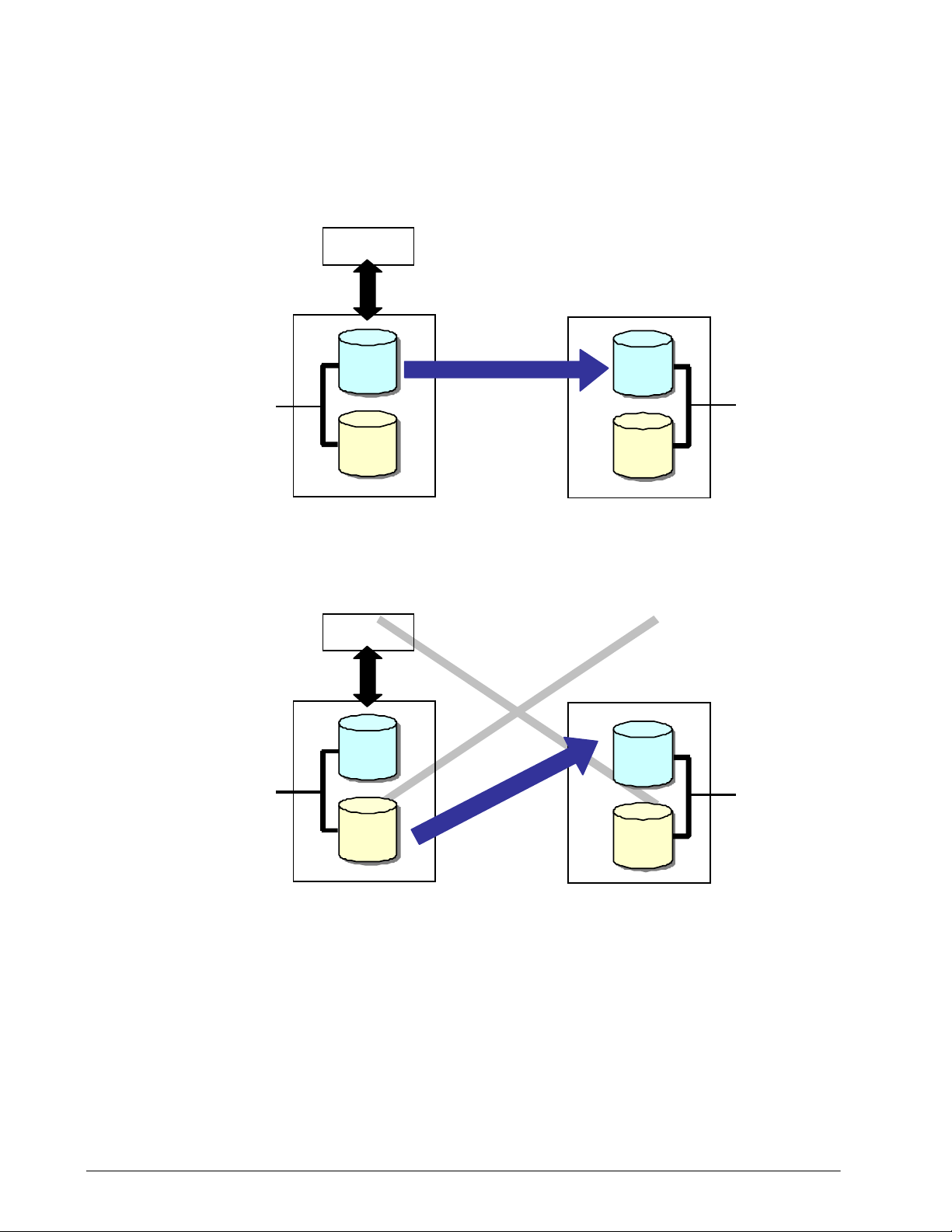
Cascade connection with P-VOL of ShadowImage
The SnapShot P-VOL can cascade the ShadowImage P-VOL. Operations
of the SnapShot and ShadowImage pairs are restricted depending on
statuses of the pairs.
Restriction when performing restoration
When performing restoration, the pair status of the pairs must be made
different than those which make restoration Split. While the
ShadowImage pair is executing restoration, the V-VOLs of the cascaded
SnapShot cannot be Read/Write. When the restoration is completed,
Read/Write from/to all the V-VOLs will be possible again.
Figure 1-10: While restoring ShadowImage, the SnapShot V-VOL
cannot be Read/Write
Performance when cascading the P-VOL of SnapShot and ShadowImage
In the configuration in which the P-VOL of SnapShot and the P-VOL of
ShadowImage are cascaded, when SnapShot pair status is Split, and at
the same time, ShadowImage pair status is any of Paired, Paired
Internally Synchronizing, Synchronizing, and Split Pending, the
host I/O performance for the P- VOL d eter i orat es . Use Shado wIm age in
the Split status and, if needed, resynchronize the ShadowImage pair
and acquire the backup.
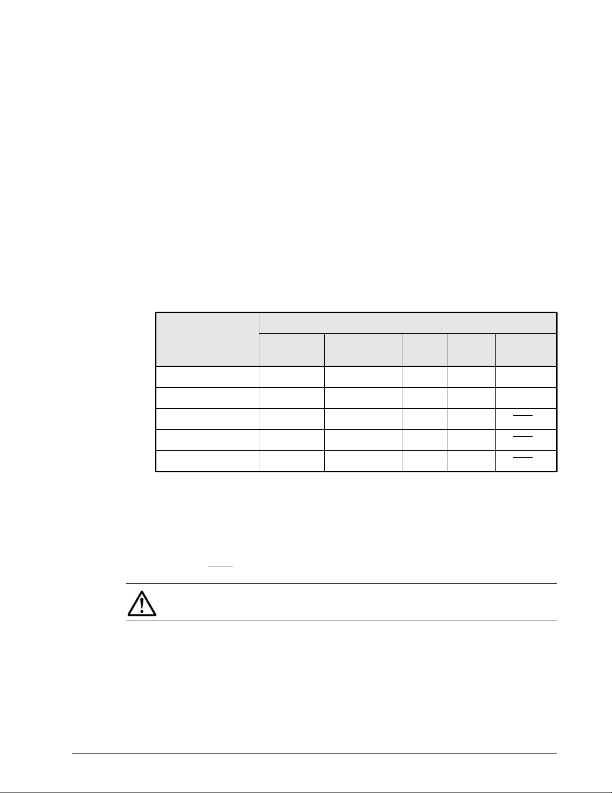
Table 1-7 shows whether a read/write from/to a P-VOL of
ShadowImage is possible or not in the case where a P-VOL of SnapShot
and a P-VOL of ShadowImage are the same LU.
1-22 SnapShot overview
Hitachi AMS 2000 Family Copy-on-Write SnapShot User Guide
Page 43

SnapShot P_VOL
Table 1-7: A Read/Write Instruction to a P-VOL of
Paired
(Includ-
ing
Paired
Inter-
naly
Syn-
chroniz-
ing)
Synchro-
nizing
ShadowImage
ShadowImage P_VOL
Reve
rse
Syn-
chro-
nizin
g
Split
Split
Pend-
ing
Failure
Failure
(Restor
e)
Failure
(S_VOL
Switch)
Paired
Reverse Synchro-
nizing
Split
Failure
Failure (Restore)
R/W
xx x
R/W
R/W
xx x∆
R/W
R/W
R/W
indicates a possible case, x indicates an impossible case
x
R/WR/W
x
R/W
R/WR/WR/W
R/WR/WR/W
x ∆
R/W
R/W
R/W
?
R/W
R/W
R/W
xx
xx
∆
R/W
∆
R/W
xx
∆ indicates a case where a pair operation causes an error (a case that
can occur as a result of a change of the pair status to Failure)
R/W: Read/Write by a host is possible.
R: Read by a host is possible but write is impossible.
W: Write by a host is possible but read is impossible.
R/W
: Read/Write by a host is impossible.
x
R/W
SnapShot overview 1-23
Hitachi AMS 2000 Family Copy-on-Write SnapShot User Guide
Page 44

NOTE: When using SnapShot with ShadowImage
• Failure in this table excludes a condition in which access of an LU is
not possible (for example, LU blockage).
• When one P-VOL configures a pair with one or more S-VOLs, decide
which item is applied as the pair status of the P-VOL of the abovementioned ShadowImage with the following procedure:
- If all the pairs that the P-VOL concerned configures are in the
Split status, the item of Split is applied.
- If all the pairs that the P-VOL concerned configures are in the
Split status or the Failure status, the item of Split is applied.
However, when including the pair that became Failure during
restore, the items of Failure (Restore) are applied.
- If a pair in the Paired status, the Synchronizing status, or the
Reverse Synchronizing status is included in the pair that the PVOL concerned configures, the item of Paired, Synchronizing,
and Reverse Synchronizing is applied, respectively.
Cascade restrictions with S-VOL of ShadowImage
Cascade of an LU of SnapShot with an S-VOL of ShadowImage, is
supported only when the S-VOL of ShadowImage and a P-VOL of
SnapShot are the same LU. Also, operations of the ShadowImage and
SnapShot pairs are restricted depending on statuses of the pairs.
• Restriction of pair creation order. When cascading a P-VOL of
SnapShot with an S-VOL of ShadowImage, create a ShadowImage
pair first. When a SnapShot pair is created earlier, delete the
SnapShot pair once and create a pair using ShadowImage
• Restriction of Split Pending. When the ShadowImage pair
status is Split Pending, the SnapShot pair cannot be changed to
the Split status. Execute it again after changing the ShadowImage
pair status to other than Split Pending.
• Changing the SnapShot pair to Split while copying
ShadowImage.
status while the ShadowImage pair status is Synchronizing or
Paired Internally Synchronizing, the V-VOL data of SnapShot
cannot be guaranteed. This is because the status where the
background copy of ShadowImage is operating is determined as the
V-VOL data of SnapShot.
When the SnapShot pair is changed to the Split
• Performing pair re-synchronization when the
ShadowImage pair status is Failure.
synchronized when the ShadowImage pair status is Failure, all
data is copied from the P-VOL to the S-VOL of ShadowImage. When
the SnapShot pair status is Split, all data of the P-VOL of SnapShot
is saved to the V-VOL. Be careful of the free capacity of the data
pool used by the V-VOL.
If a pair is re
1-24 SnapShot overview
Hitachi AMS 2000 Family Copy-on-Write SnapShot User Guide
Page 45

• Performance at the time of cascading the P-VOL of
SnapShot and the S-VOL of ShadowImage.
In the
configuration in which the P-VOL of SnapShot and the S-VOL of
ShadowImage are cascaded, when SnapShot pair status is Split,
and the ShadowImage pair status is any of Paired, Paired
Internally Synchronizing, Synchronizing, and Split Pending,
the host I/O performance for the P-VOL of ShadowImage
deteriorates. Use ShadowImage in the Split status and, if needed,
resynchronize the ShadowImage pair and acquire the backup.
SnapShot P_VOL
Paired
Reverse
Synchronizing
Table 1-8
shows whether a read/write from/to an S-VOL of
ShadowImage is possible when a P-VOL of SnapShot and an S-VOL of
ShadowImage are the same LU.
Table 1-8: A Read/Write Instruction to a S-VOL of
ShadowImage
ShadowImage S-VOL
Paired
(Includi
ng
Paired
Internal
y
Synchroni
zing
Synchro
nizing)
R
xx x
R
Reve
rse
Sync
hroni
zing
R
Split
Split
R/WR/W
R/W
Pendin
xxxx
Failure
Failure
g
R
(Restor
e)
R/W
Failure
(S_VOL
Switch)
R/W
Split
Failure
Failure (Restore)
R
R
xx x∆
R
R
indicates a possible case, x indicates an impossible case
R
R
R/WR/W
R/WR/W
x ∆
R/W
R
R
R/W
∆
R/W
∆
R/W
xx
∆ indicates a case where a pair operation causes an error (a case that
can occur as a result of a change of the pair status to Failure)
R/W: Read/Write by a host is possible.
R: Read by a host is possible but write is impossible.
W: Write by a host is possible but read is impossible.
R/W
: Read/Write by a host is impossible.
SnapShot overview 1-25
?
R/W
R/W
Hitachi AMS 2000 Family Copy-on-Write SnapShot User Guide
Page 46

NOTE: When using SnapShot with ShadowImage
• Failure in this table excludes a condition in which access of an LU is
not possible (for example, LU blockage).
• When one P-VOL configures a pair with one or more S-VOLs, decide
which item is applied as the pair status of the P-VOL of the abovementioned ShadowImage with the following procedure:
- If all the pairs that the P-VOL concerned configures are in the
Split status, the item of Split is applied.
- If all the pairs that the P-VOL concerned configures are in the
Split status or the Failure status, the item of Split is applied.
However, when including the pair that became Failure during
restore, the items of Failure (Restore) are applied.
- If a pair in the Paired status, the Synchronizing status, or the
Reverse Synchronizing status is included in the pair that the PVOL concerned configures, the item of Paired, Synchronizing,
and Reverse Synchronizing is applied, respectively.
1-26 SnapShot overview
Hitachi AMS 2000 Family Copy-on-Write SnapShot User Guide
Page 47

Pair Operation Restrictions when Cascading SnapShot with ShadowImage
Table 1-9 to Table 1-12 on page 1-29 shows pair status and operation
when cascading SnapShot with ShadowImage. The shaded areas in the
tables indicate unworkable combinations.
Table 1-9: ShadowImage pair operation when LU shared
with P-VOL on ShadowImage and P-VOL on SnapShot (1)
SnapShot Pair Status
ShadowImage
Operation
Paired
Reverse
Synchronizing
Split Failure
Failure
(Restore)
Creating pairs
Splitting pairs
Re-synchronizing
pairs
Restoring pairs
Deleting pairs
x x
x x
xx x
SnapShot overview 1-27
Hitachi AMS 2000 Family Copy-on-Write SnapShot User Guide
Page 48

SnapShot
Operation
Table 1-10: SnapShot pair operation when LU shared with
P-VOL on ShadowImage and P-VOL on SnapShot (2)
ShadowImage Pair Status
Paired
(Includi
ng
Paired
Internal
y
Synchro
nizing)
Synchroni
zing
Reve
rse
Sync
hroni
zing
Split
Split
Pendin
g
Failure
Failure
(Restor
e)
Failure
(S_VOL
Switch)
qCreating pairs
Splitting pairs
Re-synchronizing
pairs
Restoring pairs
Deleting pairs
xx
x
x xx
xx x x xx
Table 1-11: ShadowImage pair operation when LU shared
with S-VOL on ShadowImage and P-VOL on SnapShot (1)
SnapShot Pair Status
ShadowImage
Operation
Creating pairs
Splitting pairs
Paired
xx xxx
Reverse
Synchronizing
Split Failure
Failure
(Restore)
Re-synchronizing
x x
pairs
Restoring pairs
Deleting pairs
x x
1-28 SnapShot overview
Hitachi AMS 2000 Family Copy-on-Write SnapShot User Guide
Page 49

SnapShot
Operation
Table 1-12: SnapShot Pair Operation when LU Shared
with S-VOL on ShadowImage and P-VOL on SnapShot (2)
ShadowImage Pair Status
Paired
(Includi
ng
Paired
Internal
y
Synchro
nizing)
Synchroni
zing
Reve
rse
Sync
hroni
zing
Split
Split
Pendin
g
Failure
Failure
(Restor
e)
Failure
(S_VOL
Switch)
Creating pairs
Splitting pairs
Re-synchronizing
pairs
Restoring pairs
Deleting pairs
x
x
x
xx x xxxx
SnapShot overview 1-29
Hitachi AMS 2000 Family Copy-on-Write SnapShot User Guide
Page 50

Simultaneous Cascading Restrictions with ShadowImage P-VOL and S-VOL
When the firmware version of the array is 08B0/A or more, the P-VOL
and the S-VOL of ShadowImage can cascade SnapShot at the same time
as shown in
the status of Paired, Paired Internally Synchronizing,
Synchronizing, or Split Pending and operating SnapShot in the Split
status as is, the performance deteriorates significantly. Start the
operation after advance verification
Figure 1-11. However, when operating ShadowImage in
Figure 1-11: Simultaneous Cascading Restrictions with
ShadowImage P-VOL and S-VOL
• LU Ownership. When cascading the P-VOL and the S-VOL of
ShadowImage and SnapShot at the same time, if the owner controllers
which the data pool for SnapShot specified at the time of SnapShot pair
creation belongs are different, the pair creation is guarded. Execute the
pair operation again by changing the ownership of the specified data
pool for SnapShot or specifying the other data pool for SnapShot.
• Be careful when changing the LU ownership in the configuration in
which the P-VOL and the S-VOL of ShadowImage and SnapShot are
cascaded at the same time. Since the LU ownership change processing
operates for all LUs in the cascaded configuration and all other
SnapShot pairs using the data pool for SnapShot in the relevant pair
configuration, the performance deterioration occurs at the time of
execution. To change the ownership, perform it when the load of the
array is low.
1-30 SnapShot overview
Hitachi AMS 2000 Family Copy-on-Write SnapShot User Guide
Page 51

Figure 1-12: Changing LU Ownership
Cascade Restrictions of TrueCopy with ShadowImage and SnapShot
When the firmware version of the array is 08B0/A or more, SnapShot
can cascade ShadowImage and TrueCopy at the same time. However,
since the performance may deteriorate, start the operation after
advance verification.
• Cascade restrictions of TrueCopy S-VOL with SnapShot V-
In the configuration in which the P-VOL of ShadowImage and
Vol.
the P-VOL of SnapShot are cascaded as shown in
at the same time, in the configuration in which the V-VOL of
SnapShot and the S-VOL of TrueCopy are cascaded, when the
TrueCopy pair status is Paired or Synchronizing, ShadowImage
cannot be restored. Change the TrueCo py pair status to Split, and
then execute it again.
Figure 1-13, and
Figure 1-13: Cascade restrictions of TrueCopy S-VOL with
SnapShot V-VOL
SnapShot overview 1-31
Hitachi AMS 2000 Family Copy-on-Write SnapShot User Guide
Page 52

1-32 SnapShot overview
Hitachi AMS 2000 Family Copy-on-Write SnapShot User Guide
Page 53

2
Planning and design
A snapshot ensures that v olumes with bad or missing data can be
restored. With Copy-on-Write, you create copies of your
production data that can be used for backup and other uses.
Creating a copy system that fully supports business continuity is
best done when SnapShot is configured to match your business
needs.
This chapter guides you in planning a configuration that meets
organization needs and the workload requirements of your host
application.
The plan and design workflow
Assessing business needs
Establishing data pool size
Requirements and recommendations for SnapShot Logical
Units
Operating system considerations
Cascading SnapShot with TrueCopy
Cascading SnapShot with TrueCopy Extended Distance
Maximum supported capacity
Planning and design 2–1
Hitachi AMS 2000 Family Copy-on-Write SnapShot User Guide
Page 54

The plan and design workflow
The SnapShot planning effort consists of determining the number of
V-VOLs required by your organization, the V -VOL(s)’ lifespan, that is,
how long they must be held before being updated again, the
frequency that snapshots are taken, and the size of the data pool.
This information is found by analyzing business needs and measuring
write workload sent by the host application to the primary volume.
The plan and design workflow consists of the following:
• Assess business needs.
• Determine how often a snapshot should be taken.
• Determine how long the snapshot should be held.
• Determine the number of snapshot copies required per P-VOL.
• Measure production system write workload.
• Size the data pool. (For a description of the data pool, see Data
pools on page 1-4.
These objectives are addressed in detail in this chapter. Two other
tasks are required before your design can be implemented, which are
also addressed in this chapter:
• When you have established your SnapShot system design, the
system’s maximum allowed capacity must be calculated. This
has to do with how the array manages storage segments.
• Equally important in the planning process are the ways that
various operating systems interact with SnapShot.
Assessing business needs
Business needs have to do with how long back-up data needs to be
retained and what the business or organization can tolerate when
disaster strikes.
The following organizational priorities help determine the following:
• How often a snapshot should be made (frequency)
• How long a snapshot (the V-VOL) should be held (lifespan)
• The number of snapshots (V-VOLs) tha t will be required for the
P-VOL.
Copy frequency
How often copies need to be made is determined by how much data
could be lost in a disaster before business is significantly impacted.
To determine how often a snapshot should be taken
Decide how much data could be lost in a disaster without
significant impact to the business.
2-2 Planning and design
Hitachi AMS 2000 Family Copy-on-Write SnapShot User Guide
Page 55

Ideally, a business desires no data loss. But in the real world,
disasters occur and data is lost. You or your organization’s
decision makers must decide the number of business
transactions, the number of hours required to k e y in lost data,
and so on.
If losing 4 hours of business transaction is acceptable, but not
more, backups should be planned every 4 hours. If 24 hours of
business transaction can be lost, backups may be planned every
24 hours.
Determining how often copies should be made is one of the factors
used to determine data pool size. The more time that elapses
between snapshots, the more data accumulates in the data pool.
Copy frequency may need to be modified to reduce the data pool
size.
Selecting a reasonable time between Snapshots
The length of time between snapshots, if too short or too long, can
cause problems.
• When short periods are indicated by your company’s business
needs, consider also that snapshots taken too frequently could
make it impossible to recognize logical errors in the storage
system. This would result in snapshots of bad data. How long
does it take to notice and correct such logical errors? The time
span for snapshots should provide ample time to locate and
correct logical errors in the storage system.
• When longer periods between snapshots are indicated by
business needs, consider that the longer the period, the more
data accumulates in the data pool. Longer periods between
backups require more space in the data pool.
This effect is multiplied if more than one V-VOL is used. If you hav e
two snapshots of the P-VOL, then two V-VOLs are tracking changes
to the P-VOL at the same time.
Establishing how long a copy is held (copy lifespan)
Copy lifespan is the length of time a copy (V-VOL) is held, before a
new backup is made to the volume. Lifespan is determined by two
factors:
• Your organization’ s data retention policy for holding onto backup
copies.
• Secondary business uses of the backup data.
Lifespan based on backup requirements
• If the snapshot is to be used for tape backups, the minimum
lifespan must be => the time required to copy the data to tape.
For example:
Planning and design 2-3
Hitachi AMS 2000 Family Copy-on-Write SnapShot User Guide
Page 56

Hours to copy a V-VOL to tape = 3 hours
V-VOL lifespan => 3 hours
• If the snapshot is to be used as a disk-based backup available
for online recovery, you can determine the lifespan by
multiplying the number of generations of backup you want to
keep online by the snapshot frequency. For example:
Generations held = 4
Snapshot frequency = 4 hours
4 x 4 = 16 hours
V-VOL lifespan = 16 hours
Lifespan based on business uses
• If you use snapshot data (the V-VOL) for testing an application,
the testing requirements determine the amount of time a
snapshot is held.
• If snapshot data is used for development purposes, development
requirements may determine the time the snapshot is held.
• If snapshot data is used for business reports, the reporting
requirements can determine the backup’s lifespan.
Establishing the number of V-VOLs
V-VOL frequency and lifespan determ ine the number of V- VOLs your
system needs per P-VO L.
For example: Suppose your data must be backed up every 12 hours,
and business-use of the data in the V-VOL requires holding it for 48
hours. In this case, your SnapShot system would require 4 V-VOLs,
since there are four 12-hour intervals during the 48-hour period. This
is illustrated in Figure 2-1.
•
Figure 2-1: V-VOL Frequency, Lifespan
2-4 Planning and design
Hitachi AMS 2000 Family Copy-on-Write SnapShot User Guide
Page 57

Establishing data pool size
The data pool holds data from the P-VOL that is being replaced. By
holding this original data in the data pool, the mirror image of the PVOL at the time of the snapshot is maintained.
You determine the siz e of the data pool that your system requires by:
• Measuring the amount of write workload that passes from the
host application to the P-VOL. Write workload is the megabytes
per second that are written to the primary volume over a specific
time.
• Calculating the amount of data that would accumulate during
the lifespan of your V-VOL.
• Multiplying the amount of data that accumulates by the number
of V-VOLs.
•
Figure 2-2: Write workload and data pool size
Measuring workload data, sizing the data pool
To set up SnapShot, you must measure the amount of data that
changes in your production system. The amount of data written to
the primary volume indicates how large the data pool must be.
Workload data is collected using performance monitoring software on
your operating system—preferably during the busiest time of month,
quarter , and year. The goal is to collect data that shows y our system’s
actual workloads during high peaks and spikes, when more is
changing and the demands on the system are greatest.
To collect workload data and size the data pool
1. Using your operating system’s performance monitoring software,
collect the following:
- Disk-write bytes/second for every physical volume that will
be replicated.
- Collect this data at 10 minute intervals.
Planning and design 2-5
Hitachi AMS 2000 Family Copy-on-Write SnapShot User Guide
Page 58

- Collect this data over a 4-6 week period that includes high
peaks and spikes, and when the demands on the system are
greatest.
•
2. At the end of the period, convert the data to MB/second and
import into a spreadsheet tool. Figure 2-3 shows collected raw
data, in megabytes per second in 10 minute segments.
•
Figure 2-3: Raw Data Example in MB/sec
3. Using the copy frequency established earlier, calculate averages
over the collection period. Most spreadsheet tools have an
average function. For example:
If copy frequency is 1 hour, then calculate 60 minute rolling
averages using the values in 6 10-minute intervals.
If copy frequency is 4 hours, then calculate 240 minute rolling
averages using the values in 24 10-minute intervals.
Figure 2-4 illustrates 60-minute rolling averages.
2-6 Planning and design
Hitachi AMS 2000 Family Copy-on-Write SnapShot User Guide
Page 59

•
Figure 2-4: Rolling Averages Calculated Using V-VOL Frequency
Example rolling-average procedure using Microsoft Excel:
a. In cell C4, type =Average(b2:b7).
b. Press Enter.
This instructs the tool to calculate the average value in cells
B2 through B7 and populates C4 with that data.
c. Copy the value in C4.
d. Highlight cells C5 to the last C cell in the last row of workload
data in the spreadsheet.
e. Right-click the highlighted cells and select the paste option.
Excel maintains the logic and increments the formula values
initially entered in C4. It then calculates all the point in time
averages and populates the C cells.
Figure 2-5 illustrates rolling averages graphed over raw
measurement data averages.
Planning and design 2-7
Hitachi AMS 2000 Family Copy-on-Write SnapShot User Guide
Page 60

•
Figure 2-5: Rolling Averages Graphed Over Raw Averages
4. Locate the maximum rolling average (RA) value in the C column.
Using this peak value and the following formula, calculate the
cumulative peak data change over the lifespan of a copy (V- VOL):
(RA peak MB/sec) x (V-VOL lifespan seconds) =
(Cumulative data over V-VOL lifespan)
For example, if the RA peak is 25 MB/sec, and the V-VOL lifespan
is 3600 seconds (1 hour), then:
25MB/sec x 3600 seconds = 90,000 MB
Cumulative data over a V-VOL’s 1-hour lifespan is 90,000 MB.
5. Calculate the base data pool size for your primary/virtual volumes
by multiplying the MB size of one V-VOL in Step 4 by the number
of V-VOLs, which was established earlier. For example:
90,000 MB
x 4 V-VOLS = 360,000 MB
This is the base data pool size for a SnapShot system in which the
copy frequency is 1 hour, the copy lifespan is 4 hours, and the
number of copies (V-VOLs) is 4.
6. It is highly recommended that a safety factor of 20%, be
calculated. Do so using the following formula:
(Base data pool size) x 1.2. For example:
2-8 Planning and design
Hitachi AMS 2000 Family Copy-on-Write SnapShot User Guide
Page 61

360,000 MB x 1.2 = 432,000 MB
7. It is also advisable to factor in annual increases in data
transactions. Do this by multiplying the base pool size by the
percentage of expected annual growth. For example:
432,000 MB x 1.2 (20 percent growth rate for per year)
= 518,400 MB
This is the size of the data pool with growth factored for the first
year.
8. Repeat this step for each year the solution will be in place. For
example:
518, 400 MB x 1.2 (20 percent growth rate for second
year)
= 622,080 MB
This is the size of the data pool with growth factored for the
second year.
Rule-of-thumb calculation
When write-workload has not been measured, Hitachi suggests the
change rates shown in Table 2-1.
•
Table 2-1: Workload Rates when No Measurement
Snapshot lifespan
1-4 hours 10%
4-8 hours 15%
8-12 hours 20%
12-24 hours 25%
Suggested write workload
change rate
To calculate data pool size using rule-of-thumb change rate
1. Use the following formula:
Data Pool size = (P-VOL x % of changed data x 2.5 safety
rate) x number of V-VOLs
For example, if the P-VOL = 1 TB and one snapshot is taken per
24 hours, then:
1 TB x 25% change rate x 25% safety rate of = 625 GB
2. Multiply the data pool size by the number of V-VOLs. Thus:
4 V-VOLs x 625 GB = 2500 GB (2.5 TB).
Data pool key points
• The data pool must be on the same controller as the P-VOL and
V-VOL(s).
• Data pool capacity should be at least 20 GB.
Planning and design 2-9
Hitachi AMS 2000 Family Copy-on-Write SnapShot User Guide
Page 62

• Up to 64 volumes can be assigned to a data pool.
• When a volume is assigned to a data pool, it is no longer
recognized by a host.
Requirements and recommendations for SnapShot Logical Units
Please review the following key rules and recommendations
regarding P-VOLS, V-VOLS, and data pools. See Appendix A,
Specifications, for general specifications required for SnapShot.
• Primary and secondary volumes must be set up prior to making
SnapShot copies.
• The P-VOL and S-VOL must be assigned to the same controller.
• Assign four or more disks to SnapShot LUs for optimal host and
copying performance.
• Volumes used for other purposes should not be assigned as a
primary volume. If such a volume must be assigned, move as
much of the existing write workload to non-SnapShot volumes
as possible.
• If multiple P-VOLs are located in the same drive, the status of
the pairs should stay the same (Simplex, Paired, and Split).
When status differs, performance is difficult to estimate.
RAID configuration for LUs assigned to SnapShot
Please observe the following regarding RAID levels when setting up
SnapShot pair volumes, data pools, command devices, and
Differential Management LUs.
• More than one pair may exist on the same RAID group on the
array. However, when more than two pair are assigned to the
same group, the impact on performance increases. Therefore, it
is recommended that when creating pairs within the same RAID
group, you should standardize the controllers that control LUs in
the RAID group.
• Performance is best when P-VOL and data pool are assigned to a
RAID group consisting of SAS drives, SAS7.2K drives, SSD
drives, or SAS (SED) drives. Performance decreases when
located on SATA drives.
• Multiple data pool volumes can exist on a single array, but the
RAID group for each data pool volume should be restricted only
to that POOL, otherwise performance is impacted.
• Locate a P-VOL and associated data pool in different ECC groups
within a RAID group, as shown in Figure 2-6. When they are in
the same ECC group, performance decreases and the chance of
failure increase.
2-10 Planning and design
Hitachi AMS 2000 Family Copy-on-Write SnapShot User Guide
Page 63

•
Figure 2-6: Locating P-VOL, Data Pool in Separate ECC Groups
• The P-VOL and data pool require a RAID level with redundancy.
RAID 0 is not supported.
• The P-VOL and data pool may exist on different RAID lev els and/
or number of drives in RAID. Performance improves, however,
when the RAID levels and number of drives are the same.
Table 2-2 shows RAID configurations for the P-VOL and data
pool.
Planning and design 2-11
Hitachi AMS 2000 Family Copy-on-Write SnapShot User Guide
Page 64

•
Table 2-2: P-VOL and Data Pool RAID Configuration
P-VOL Data Pool
RAID 1+0
(N = 1 to 8)
RAID 1+0
(N = 1 to 8)
RAID 5 (N = 4) (see
Note 1)
RAID 5 (When N = 4)
(see Note 1)
RAID 5 (When N = 8)
(see Note 1)
RAID 6 (When N = 4)
(see Note 2)
RAID 6 (When N = 8)
(see Note 2)
RAID 6 (When N = 4)
(see Note 2)
Amount of
User Data
RAID 1+0
(N = 1 to 8)
RAID 5 (N = 4) (see
Note 1)
RAID 1+0 (N = 1 to 8) 1 1.25+2 = 3.25 1/3.25
RAID 5 (When N = 4)
(see Note 1)
RAID 5 (When N = 8)
(see Note 1)
RAID 6 (When N = 4)
(see Note 2)
RAID 6 (When N = 8)
(see Note 2)
RAID 5 (When N = 4)
(see Note 1)
14 ¼
1 2+1.25 = 3.25 1/3.25
1 1.25+1.25 = 2.5 1/2.5
1 1.125+1.125 =
1 1.5+1.5 = 3 1/3
1 1.25+1.25 = 2.5 1/2.5
1 1.5+1.25 = 2.75 1/2.75
Total Amount of
SnapShot
2.25
Share of User
Data
1/2.25
Note 1: Capacity = (1+1/N) where N = Number of data drives in
RAID
Note 2: Capacity = (1+2/N) where N = Number of data drives in
RAID
• RAID 5 (4D+1)/RAID 5 (4D+1) is the recommended
configuration because 4D+1P is a recommended configuration
for performance. It is also a balanced ratio of redundancy and
user data related to RAID 5.
• When two or more command devices are located in the same
AMS array, assign them to respective RAID groups. This
safeguards the SnapShot system in the event of system
malfunction, in which case both command devices would
become unavailable.
• When two Differential Management LUs are located in the
same AMS array, assign them to respective RAID groups. This
safeguards the SnapShot system in the event of system
malfunction, in which case both DM-LUs would become
unavailable.
2-12 Planning and design
Hitachi AMS 2000 Family Copy-on-Write SnapShot User Guide
Page 65

Operating system considerations
The following sections provide recommendations and restrictions for
SnapShot volumes.
Identifying P-VOL and V-VOL LUs on Windows
In the Navigator 2 GUI, the P-VOL and S- VOL are identi fied by their
LU number. In Windows, LUs are identified by their HLUN. The
following instructions provide procedures for the iSCSI and fibre
channel interfaces.T o understand the mapping of a LUN on Windows,
proceed as follows:
1. Identify the HLUN of your Windows disk.
a. From the Windows Server 2003 Control Panel, select
Computer Management/Disk Administrator.
b. Right-click the disk whose HLUN you want to know, then
select Properties. The number displayed to the right of “LUN”
in the dialog window is the HLUN.
2. Identify HLUN-to-LUN Mapping for the iSCSI interface as follows.
(If using fibre channel, skip to Step 3.)
a. In the Navigator 2 GUI, select the desired array.
b. In the array tree, click the Group icon, then click the iSCSI
Targets icon.
c. Click the iSCSI Target that the volume is mapped to.
d. On the screen for the host group, click the Logical Units tab.
The volumes mapped to the Host Group display. You can
confirm the LUN is mapped to the H-LUN.
WARNING! Your host group changes will be applied to multiple ports. This
change will delete existing host group mappings and corresponding Host
Group IDs, corrupting or removing data associated with the host groups. To
keep specified host groups you do not want to remove, please cancel this
operation and make changes to only one host group at a time.
3. Identify HLUN-to-LUN Mapping for the Fibre Channel interface, as
follows:
a. In the Navigator 2 GUI, select the desired array.
b. In the array tree that displays, click the Groups icon, then
click the Host Groups icon in the Groups tree.
WARNING! Your host group changes will be applied to multiple ports. This
change will delete existing host group mappings and corresponding Host
Group IDs, corrupting or removing data associated with the host groups. To
keep specified host groups you do not want to remove, please cancel this
operation and make changes to only one host group at a time.
Planning and design 2-13
Hitachi AMS 2000 Family Copy-on-Write SnapShot User Guide
Page 66

c. On the Host Groups screen, select a Host Group.
d. On the host group screen, select the Logical Units tab. Find
the identified H-LUN. The LUN displays in the next column.
e. If the HLUN is not present on a host group target screen, on
the Host Groups screen, select another Host group and repeat
Step d.
LU mapping
You cannot pair a P-VOL and V -VOL when their mapping information
has not been defined in the configuration definition file. To prevent a
host from recognizing a P-VOL or V- VOL, use LUN Manager to either
map them to a port that is not connected to the host or map them to
a host group that does not have a registered host. If y ou use Storage
Navigator instead of LUN Manager, you need only perform this task
with either the P-VOL or V-VOL.
Cluster and path switching software
Do not make the V-VOL an object of cluster or path switching
software.
Microsoft Cluster Server (MSCS)
• A host cannot recognize both a P-VOL and its V-VOL at the same
time. Map the P-VOL and V-VOL to separate hosts.
• When setting the V-VOL to be recognized by the host, use the
CCI mount command rather than Disk Administrator.
• Do not place the MSCS Quorum Disk in CCI.
• The command device cannot be shared between different hosts
in the cluster.
• Assign the exclusive command device to each host.
AIX
• A host cannot recognize both a P-VOL and its V-VOL at the same
time. Map the P-VOL and V-VOL to separate hosts.
• Multiple V-VOLs per P-VOL cannot be recognized from the same
host. Limit host recognition to one V-VOL.
Veritas Volume Manager (VxVM)
A host cannot recognize both a P-VOL and its V-VOL at the same
time. Map the P-VOL and V-VOL to separate hosts.
Windows 2000
• A P-VOL and S-VOL cannot be made into a dynamic disk on
Windows Server 2000.
2-14 Planning and design
Hitachi AMS 2000 Family Copy-on-Write SnapShot User Guide
Page 67

• Multiple V-VOLs per P-VOL cannot be recognized from the same
host. Limit host recognition to one V-VOL.
• When mounting a volume, use the CCI mount command, even if
using the Navigator 2 GUI or CLI to operate the pairs. Do not
use the Windows mountvol command because the data residing
in server memory is not flushed. The CCI mount command does
flush data in server memory, which is necessary for SnapShot
operations. For more information, see the Hitachi Adaptable
Modular Storage Command Control Interface (CCI) Reference
Guide.
Windows Server and SnapShot configuration
• Multiple V-VOLs per P-VOL cannot be recognized from the same
host. Limit host recognition to one V-VOL.
Volume mount:
• In order to make a consistent backup using a storage-based
replication such as SnapShot, you must have a way to flush the
data residing on the server memory to the array, so that the
source volume of the replication has the complete data. Y ou can
flush the date on the server memory using the umount
command of CCI to un-mount the volume. When using the
umount command of CCI for un-mount, use the mount
command of CCI for mount. For more detail about mount/
umount command, see the Hitachi Adaptable Modular Storage
Command Control Interface (CCI) Reference Guide.
• If you are using Windows Server 2003, mountvol /P to flush data
on the server memory when un-mounting the volume is
supported. Please understand the specification of the command
and run sufficient test before you use it for your operation.
• In Windows Server 2008, use the umount command of CCI to
flush the data on the memory of the server at the time of the
unmount. Do not use the mountvol command of Windows
standard. Refer to the Hitachi Adaptable Modular Storage
Command Control Interface (CCI) Reference Guide for the detail
of the restrictions of Windows Server 2008 when using the
mount/umount command.
• Windows may write for the un-mounted volume. If a pair is
resynchronized while remaining the data to the S-VOL on the
memory of the server, the compatible backup cannot be
collected. Therefore, execute the sync command of CCI
immediately before re-synchronizing the pair for the unmounted S-VOL.
Volumes recognized by the host:
• If you recognize the P-VOL and S-VOL on Windows Server 2008
at the same time, it may cause an error because the P-VOL and
S-VOL have the same disk signature. When the P-VOL and V-
Planning and design 2-15
Hitachi AMS 2000 Family Copy-on-Write SnapShot User Guide
Page 68

VOL have the same data, split the pair and then rewrite the disk
signature so that they can retain different disk signatures can
use the uniqueid command to rewrite a disk signature. See the
Hitachi Adaptable Modular Storage Command Control Interface
(CCI) Reference Guide for the detail.
Command devices
When a path detachment, which is caused by a controller
detachment or interface failure, continues for longer than one
minute, the command device may be unable to be recognized at the
time when recovery from the path detachment is made. To make the
recovery, execute the "re-scanning of the disks" of Windows. When
Windows cannot access the command device although CCI is able to
recognize the command device, restart CCI.
Linux and LVM configuration
A host cannot recognize both a P-VOL and its V-VOL at the same
time. Map the P-VOL and V-VOL to separate hosts.
Tru64 UNIX and SnapShot configuration
When rebooting the host, the pair should be split or un-recognized
by the host. Otherwise, a system reboot takes a longer amount of
time.
Concurrent use of Cache Partition Manager
When SnapShot is used together with Cache Partition Manager,
please refer to the
Reference Guide
Hitachi Storage Navigator Modular 2 Storage Features
.
VMWare and SnapShot configuration
When creating a backup of the virtual disk in the vmfs format using
SnapShot, shutdown the virtual machine that accesses the virtual
disk, and then split the pair.
If one LU is shared by multiple virtual machines, shutdown all the
virtual machines that share the LU when creating a backup.
Therefore, it is not recommended to share one LU by multiple virtual
machines in the configuration that creates a backup using SnapShot.
The VMWare ESX has a function to clone the virtual machine.
Although the ESX clone function and SnapShot can be linked,
cautions are required for the performance at the time of execution.
For example, when the volume which becomes the ESX clone
destination is a SnapShot P-VOL pair whose pair status is Paired,
since the data is written to the S-VOL for writing to the P-VOL, the
time required for a clone may become longer and the clone may be
terminated abnormally in some cases. T o avoid this, we recommend
2-16 Planning and design
Hitachi AMS 2000 Family Copy-on-Write SnapShot User Guide
Page 69

the operation to make the SnapShot pair status Split or Simplex and
to resynchronize or create the pair after executing the ESX clone.
Also, it is the same for executing the functions such as migration the
virtual machine, deploying from the template, and inflating the
virtual disk and Space Reclamation.
Figure 2-7: VMWare ESX
When using the volume in the following status, disable (0) the
VMFS3.HardwareAcceleratedLocking setting.
• The P-VOL or the S-VOL of the pairs which configures the
cascade of ShadowImage and SnapShot.
When VMFS3.HardwareAcceleratedLocking is enabled (1) in the
above-mentioned status, the volume may not be recognized. If the
volume cannot be recognized, recover it by using this procedure:
1. Set VMFS3.HardwareAcceleratedLocking to disabled (0).
2. Rescan the storage.
When the virtual OS was created on the volume which could not be
recognized, the virtual OS may not recover ev en after the volume is
re-realized. In that case, do the following:
1. Delete the virtual OS once, and re-register the virtual OS in the
data store of the volume which was re-realized.
2. At that time, when "Alarms" or "Authority" is set to the virtual OS,
set it again after the re-registration.
3. Also, since the object ID of the virtual OS changes after the reregistration when the middleware is used, review the setting.
Planning and design 2-17
Hitachi AMS 2000 Family Copy-on-Write SnapShot User Guide
Page 70

Concurrent use of Dynamic Provisioning
Observe the following items:
• When the array firmware version is less than 0893/A, the DPVOLs created by Dynamic Provisioning cannot be set for a P-VOL
of SnapShot. Moreover, when the array firmware version is less
than 0893/A, the DP-VOLs cannot be added to the data pool
used by SnapShot and TCE.
• Depending on the installed cache memory , Dynamic Provisioning
and SnapShot may not be unlocked at the same time. To unlock
Dynamic Provisioning and SnapShot at the same time, add
cache memories. For the capacity of the supported cache
memory, re fer to User data area of cache memory.
• The data pool used by SnapShot and TCE cannot be used as a
DP pool of Dynamic Provisioning. Moreover, the DP pool used by
Dynamic Provisioning cannot be used as data pools of SnapShot
and TCE.
When the array firmware version is 0893/A or more, the DP-VOLs
created by Dynamic Provisioning can be set for a P-VO L or a data
pool of SnapShot. However, the normal LU and the DP-VOL cannot
coexist in the same data pool.
The points remember when using SnapShot and Dynamic
Provisioning together are described as follows. Refer to the Hitachi
Adaptable Modular Storage Dynamic Provisioning User's Guide for
the detailed information regarding Dynamic Provisioning.
Hereinafter, the LU created in the RAID group is called a normal LU,
and the LU created in the DP pool that is created by Dynamic
Provisioning is called a DP-VOL.
• When using a DP-VOL as a DMLU, check that the free capacity
(formatted) of the DP pool to which the DP-VOL belongs is 10 GB
or more, and then set the DP-VOL as a DMLU. If the free
capacity of the DP pool is less than 10 GB, the DP-VOL cannot be
set as a DMLU.
• LU type that can be set for a P-VOL or a data pool of SnapShot
The DP-VOL created by Dynamic Provisioning can be used for a
P-VOL or a data pool of SnapShot. Table 2-3 shows a combination
of a DP-VOL and a normal LU that can be used for a P-VOL or a
data pool of SnapShot.
Table 2-3: Combination of a DP-VOL and a Normal LU
TrueCopy
P-VOL
DP-VOL DP-VOL Available. When the pair status is Split, the data
TrueCopy
S-VOL
1
Contents
pool consumed capacity can be reduced
compared to the normal LU.
2
2-18 Planning and design
Hitachi AMS 2000 Family Copy-on-Write SnapShot User Guide
Page 71

Table 2-3: Combination of a DP-VOL and a Normal LU
TrueCopy
P-VOL
DP-VOL Normal LU Available. The P-VOL consumed capacity can be
Normal LU DP-VOL Available. When the pair status is Split, the data
1
When creating the data pool using multiple DP-VOLs, the data pool
TrueCopy
S-VOL
1
Contents
reduced compared to the normal LU.
pool consumed capacity can be reduced
compared to the normal LU.
cannot be created by combining the DP-VOLs which have different
setting of Enabled/Disabled for Full Capacity Mode.
2
When both the P-VOL and the data pool use DP- VOLs, a pair cannot
be created by combining the DP-VOLs which have different setting of
Enabled/Disabled for Full Capacity Mode
• Assigning the controlled processor core of a P-VOL or a data pool
that uses the DP-VOL
When the controlled processor core of the DP-VOL used for a P-
VOL or used for a data pool of SnapShot differs as well as the
normal LU, switch the P-VOL controlled processor core
assignment to the data pool controlled processor core
automatically and create a pair. (In the case of AMS2500)
• DP pool designation of a P-VOL or a data pool that uses the DP-
VOL
When using the DP-VOL created by Dynamic Provisioning for a P-
VOL or a data pool of SnapShot, using the DP-VOL designated in
a separate DP pool of a P-VOL and a data pool is recommended.
• Setting the capacity when placing the DP-VOL in the data pool
When the pair status is Split, the old data is copied to the data
pool while writing to the P-VOL. When using the DP-VOL created
by Dynamic Provisioning as the data pool of SnapShot, the
consumed capacity of the DP-VOL in the data pool is increased by
storing the old data in the data pool. If the DP-VOL of more than
or equal to the DP pool capacity is created and used for the data
pool, this processing may deplete the DP pool capacity. When
using the DP-VOL for the data pool of SnapShot, it is
recommended to set the capacity making the over provisioning
ratio 100% or less so that the DP pool capacity does not deplete.
Furthermore, the threshold value of the data pool of SnapShot
and the threshold value of the DP pool differ . Even if the data pool
use rate of SnapShot shows 10% or less, the DP pool consumed
capacity may have exceeded Depletion Alert. Check whether the
actual use rate falls below the respective threshold values of the
data pool and DP pool of SnapShot.
• Pair status at the time of DP pool capacity depletion
Planning and design 2-19
Hitachi AMS 2000 Family Copy-on-Write SnapShot User Guide
Page 72

When the DP pool is depleted after operating the SnapShot pair
that uses the DP-VOL created by Dynamic Provisioning, the pair
status of the pair concerned may be a Failure. Table 2-4 shows
the pair statuses before and after the DP pool capacity depletion.
When the pair status becomes a Failure caused by the DP pool
capacity depletion, add the DP pool capacity whose capacity is
depleted, and execute the pair operation again.
Table 2-4: Pair Statuses before/after the DP Pool Capacity Depletion
Pair Statuses after the
Pair Statuses before the DP
Pool Capacity Depletion
DP Pool Capacity
Depletion belonging to
P-VOL
Simplex Simplex Simplex
Reverse Synchronizing Reverse Synchronizing
Failure (See Note)
Paired Paired Paired
Split Split
Failure (See Note)
Failure Failure Failure
Pair Statuses after the DP
Pool Capacity Depletion
belonging to data pool
Reverse Synchronizing
Failure (See Note)
Split
Failure (See Note)
NOTE: When write is performed to the P-VOL or V-VOL to which the
capacity depletion DP pool belongs, the copy cannot be continued and the
pair status becomes a Failure.
• DP pool status and availability of pair operation
When using the DP-VOL created by Dynamic Provisioning for a P-
VOL or a data pool of the SnapShot pair, the pair operation may
not be executed depending on the status of the DP pool to which
the DP-VOL belongs. Table 2-5 shows the DP pool status and
availability of the SnapShot pair operation. When the pair
operation fails due to the DP pool status, correct the DP pool
status and execute the pair operation again.
Table 2-5: DP Pool Statuses and Availability of SnapShot Pair Operation
DP Pool Statuses, DP Pool Capacity Statuses, and DP Pool Optimization
Statuses
Pair Operation
Normal
Create pair00x0x0
Create pair
(split option)
00x0x0
Capacity in
Growth
Capacity
Depletion
Regressed Blocked
Optimization
2-20 Planning and design
Hitachi AMS 2000 Family Copy-on-Write SnapShot User Guide
DP in
Page 73

Table 2-5: DP Pool Statuses and Availability of SnapShot Pair Operation
DP Pool Statuses, DP Pool Capacity Statuses, and DP Pool Optimization
Statuses
Pair Operation
Normal
Split pair 0 0 x 0 x 0
Resync pair0 0x0x0
Restore pair0 0x0x0
Delete pair000000
Capacity in
Growth
Capacity
Depletion
Regressed Blocked
DP in
Optimization
NOTE: When the DP pool was created or the capacity was added, the
formatting operates for the DP pool. If pair creation, pair resynchronization,
or restoration is performed during the formatting, depletion of the usable
capacity may occur. Since the formatting progress is displayed when
checking the DP pool status, check if the sufficient usable capacity is
secured according to the formatting progress, and then start the operation.
• Operation of the DP-VOL during SnapShot use
When using the DP-VOL created by Dynamic Provisioning for a P-
VOL or a data pool of SnapShot, any of the operations among the
capacity growing, capacity shrinking, LU deletion, and Full
Capacity Mode changing of the DP-VOL in use cannot be
executed. To execute the operation, delete SnapShot pair of
which the DP-VOL to be operated is in use, and then execute it
again.
• Operation of the DP pool during SnapShot use
When using the DP-VOL created by Dynamic Provisioning for a P-
VOL or a data pool of SnapShot, the DP pool to which the DP-VOL
in use belongs cannot be deleted. To execute the operation,
delete the SnapShot pair of which the DP-VOL is in use belonging
to the DP pool to be operated, and then execute it again. The
attribute edit and capacity addition of the DP pool can be
executed usually regardless of the SnapShot pair.
• Cascade connection
A cascade can be performed on the same conditions as the
normal LU (refer to Cascade connection of SnapShot with
TrueCopy on page 1-12). However, the firmware version of the
array including the DP-VOL needs to be 0893/A or more.
User data area of cache memory
If SnapShot is used to secure a part of the cache memory, the user
data area of the cache memory decreases. Also, by using TCE and
Dynamic Provisioning together, the user data area may further
decrease. Table 2-6 to Table 2-13 show the cache memory secured
Planning and design 2-21
Hitachi AMS 2000 Family Copy-on-Write SnapShot User Guide
Page 74

capacity and the user data area when using the program product. For
Dynamic Provisioning, the user data area differs depending on DP
Capacity Mode. Refer to the Hitachi Adaptable Modular Storage
Dynamic Provisioning User's Guide for detailed information.
Table 2-6: Supported Capacity of the Regular Capacity Mode (H/
W Rev. is 0100)
(1 of 2)
Management
Array Type Cache Memory
Capacity for
Dynamic
Provisioning
AMS2100 1 GB/CTL 80 MB -
2 GB/CTL 512 MB
4 GB/CTL 2 GB
AMS2300 1 GB/CTL 140 mb -
2 GB/CTL 512 MB
4 GB/CTL 2 GB
8 GB/CTL 4 GB
AMS2500 2 GB/CTL 300 MB 512 MB
4 GB/CTL 1.5 GB
6 GB/CTL 3 GB
8 GB/CTL 4 GB
10 GB/CTL 5 GB
12 GB/CTL 6 GB
16 GB/CTL 8 GB
Capacity
Secured for
SnapShot or TCE
Table 2-7: Supported Capacity of the Regular Capacity Mode (H/
W Rev. is 0100)
Capacity
Secured for
Array Type
Dynamic
Provisioning
and TCE or
SnapShot
AMS2100 - 590 MB 59 0 MB N/A
580 1,520 MB 1,440 MB 940 MB
2,120 MB 3,520 MB 3,460 MB 1,400 MB
User Data
Area when
Dynamic
Provisioning,
TCE, and
SnapShot are
Disabled
2-22 Planning and design
Hitachi AMS 2000 Family Copy-on-Write SnapShot User Guide
(2 of 2)
User Data
Area when
Provisioning
Using
Dynamic
User Data
Area when
Using
Dynamic
Provisioning
and TCE or
SnapShot
Page 75

Table 2-7: Supported Capacity of the Regular Capacity Mode (H/
W Rev. is 0100)
(2 of 2)
Capacity
Secured for
Array Type
Dynamic
Provisioning
and TCE or
SnapShot
AMS2300 - 500 MB 500 MB N/A
660 MB 1,440 MB 1,300 MB 780 MB
2,200 MB 3,280 MB 3,120 MB 1,080 MB
4,240 MB 7,160 MB 7,020 MB 2,920 MB
AMS2500 800 MB 1,150 MB 850 MB N/A
1,830 MB 2,960 MB 2,660 MB 1,130 MB
3,360 MB 4,840 MB 4,560 MB 1,480 MB
4,400 MB 6,740 MB 6,440 MB 2,340 MB
5,420 MB 8,620 MB 8,320 MB 3,200 MB
6,440 MB 10,500 MB 10,200 MB 4,060 MB
8,480 MB 14,420 MB 14,120 MB 5,940 MB
User Data
Area when
Dynamic
Provisioning,
TCE, and
SnapShot are
Disabled
User Data
Area when
Using
Dynamic
Provisioning
User Data
Area when
Provisioning
and TCE or
SnapShot
Using
Dynamic
Table 2-8: Supported Capacity of the Regular Capacity Mode (H/
W Rev. is 0200)
Array Type (the
H/W Rev. is
Cache Memory
0200)
AMS2100 1 GB/CTL 80 MB -
2 GB/CTL 512 MB
4 GB/CTL 2 GB
AMS2300 1 GB/CTL 140 MB -
2 GB/CTL 512 MB
4 GB/CTL 2 GB
8 GB/CTL 4 GB
(1 of 2)
Management
Capacity for
Dynamic
Provisioning
Capacity
Secured for
SnapShot or TCE
Planning and design 2-23
Hitachi AMS 2000 Family Copy-on-Write SnapShot User Guide
Page 76

Table 2-8: Supported Capacity of the Regular Capacity Mode (H/
W Rev. is 0200)
(1 of 2)
Array Type (the
H/W Rev. is
Cache Memory
0200)
AMS2500 2 GB/CTL 300 MB 512 MB
4 GB/CTL 1.5 GB
6 GB/CTL 3 GB
8 GB/CTL 4 GB
10 GB/CTL 5 GB
12 GB/CTL 6 GB
16 GB/CTL 8 GB
Management
Capacity for
Dynamic
Provisioning
Capacity
Secured for
SnapShot or TCE
Table 2-9: Supported Capacity of the Regular Capacity Mode (H/
Array Type
W Rev. is 0200)
Capacity
Secured for
Dynamic
Provisioning
and TCE or
SnapShot
User Data
Area when
Dynamic
Provisioning,
TCE, and
SnapShot are
Disabled
(2 of 2)
User Data
Area when
Provisioning
Using
Dynamic
User Data
Area when
Using
Dynamic
Provisioning
and TCE or
SnapShot
AMS2100 - 590 MB 59 0 MB N/A
580 1,390 MB 1,310 MB 810 MB
2,120 MB 3,360 MB 3,280 MB 1,220 MB
AMS2300 - 500 MB 50 0 MB N/A
660 MB 1,340 MB 1,200 MB 680 MB
2,200 MB 3,110 MB 2,970 MB 930 MB
4,240 MB 6,490 MB 6,800 MB 2,700 MB
AMS2500 800 MB 1,150 MB 850 MB N/A
1,830 MB 2,780 MB 2,480 MB 950 MB
3,360 MB 4,660 MB 4,360 MB 1,280 MB
4,400 MB 6,440 MB 6,140 MB 2,040 MB
5,420 MB 8,320 MB 8,020 MB 2,900 MB
6,440 MB 9,980 MB 9,680 MB 3,540 MB
8,480 MB 14,060 MB 13,760 MB 5,580 MB
2-24 Planning and design
Hitachi AMS 2000 Family Copy-on-Write SnapShot User Guide
Page 77

Table 2-10: Supported Capacity of the Maximum Capacity Mode
(H/W Rev. is 0100) (1 of 2)
Management
Array Type Cache Memory
Capacity for
Dynamic
Provisioning
AMS2100 1 GB/CTL 210 MB -
2 GB/CTL 512 MB
4 GB/CTL 2 GB
AMS2300 1 GB/CTL 310 MB -
2 GB/CTL 512 MB
4 GB/CTL 2 GB
8 GB/CTL 4 GB
AMS2500 2 GB/CTL 520 MB 512 MB
4 GB/CTL 1.5 GB
6 GB/CTL 3 GB
8 GB/CTL 4 GB
10 GB/CTL 5 GB
12 GB/CTL 6 GB
16 GB/CTL 8 GB
Capacity
Secured for
SnapShot or TCE
Table 2-11: Supported Capacity of the Maximum Capacity Mode
(H/W Rev. is 0100) (2 of 2)
Capacity
Secured for
Array
Type
Dynamic
Provisioning
and TCE or
SnapShot
AMS2100 - 590 MB N/A N/A
710 MB 1,520 MB 1,310 MB 810 MB
2,270 MB 3,520 MB 3,310 MB 1,250 MB
AMS2300 - 500 MB N/A N/A
830 MB 1,440 MB 1,130 MB 610 MB
2,350 MB 3,280 MB 2,970 MB 930 MB
4,410 MB 7,160 MB 6,850 MB 2,750 MB
User Data
Area when
Dynamic
Provisioning,
TCE, and
SnapShot are
Disabled
User Data
Area when
Using
Dynamic
Provisioning
User Data
Area when
Using
Dynamic
Provisioning
and TCE or
SnapShot
Planning and design 2-25
Hitachi AMS 2000 Family Copy-on-Write SnapShot User Guide
Page 78

Table 2-11: Supported Capacity of the Maximum Capacity Mode
(H/W Rev. is 0100) (2 of 2)
Capacity
Secured for
Array
Type
Dynamic
Provisioning
and TCE or
SnapShot
AMS2500 1,022 MB 1,150 MB N/A N/A
2,078 MB 2,960 MB N/A N/A
3,600 MB 4,840 MB 4,320 MB 1,240 MB
4,620 MB 6,740 MB 6,220 MB 2,120 MB
5,640 MB 8,620 MB 8,100 MB 2,980 MB
6,660 MB 10,500 MB 9,980 MB 3,840 MB
8,700 MB 14,420 MB 13,900 MB 5,720 MB
User Data
Area when
Dynamic
Provisioning,
TCE, and
SnapShot are
Disabled
User Data
Area when
Using
Dynamic
Provisioning
User Data
Area when
Using
Dynamic
Provisioning
and TCE or
SnapShot
Table 2-12: Supported Capacity of the Maximum Capacity Mode
(H/W Rev. is 0200) (1 of 2)
Management
Array Type Cache Memory
Capacity for
Dynamic
Provisioning
AMS2100 1 GB/CTL 210 MB -
2 GB/CTL 512 MB
4 GB/CTL 2 GB
AMS2300 1 GB/CTL 310 MB -
2 GB/CTL 512 MB
4 GB/CTL 2 GB
8 GB/CTL 4 GB
AMS2500 2 GB/CTL 520 MB 512 MB
4 GB/CTL 1.5 GB
6 GB/CTL 3 GB
8 GB/CTL 4 GB
10 GB/CTL 5 GB
12 GB/CTL 6 GB
16 GB/CTL 8 GB
Capacity
Secured for
SnapShot or TCE
2-26 Planning and design
Hitachi AMS 2000 Family Copy-on-Write SnapShot User Guide
Page 79

Table 2-13: Supported Capacity of the Maximum Capacity Mode
(H/W Rev. is 0200) (2 of 2)
Capacity
Secured for
Array
Type
Dynamic
Provisioning
and TCE or
SnapShot
AMS2100 - 590 MB N/A N/A
710 MB 1,390 MB 1,180 MB 680 MB
2,270 MB 3,360 MB 3,150 MB 1,090 MB
AMS2300 - 500 MB N/A N/A
830 MB 1,340 MB 1,030 MB 510 MB
2,350 MB 3,110 MB 2,800 MB 760 MB
4,410 MB 6,940 MB 6,630 MB 2,530 MB
AMS2500 1,022 MB 1,090 MB N/A N/A
2,078 MB 2,780 MB N/A N/A
3,600 MB 4,660 MB 4,140 MB 1,060 MB
4,620 MB 6,440 MB 5,920 MB 1,820 MB
5,640 MB 8,320 MB 7,800 MB 2,680 MB
6,660 MB 9,980 MB 9,460 MB 3,320 MB
8,700 MB 14,060 MB 13,540 MB 5,360 MB
User Data
Area when
Dynamic
Provisioning,
TCE, and
SnapShot are
Disabled
User Data
Area when
Using
Dynamic
Provisioning
User Data
Area when
Provisioning
and TCE or
Using
Dynamic
SnapShot
Windows 2000/Windows Server and Dynamic Disk
In an environment of the Windows Server 2000/Windows Server , you
cannot use SnapShot pair volumes as dynamic disk. The reason for
this restriction is because in this case if you restart Windows or use
the Rescan Disks command after creating or re-synchronizing a
SnapShot pair, there are cases where the V-VOL is displayed as
Foreign in Disk Management and become inaccessable.
Planning and design 2-27
Hitachi AMS 2000 Family Copy-on-Write SnapShot User Guide
Page 80

Limitations of Dirty Data Flush Number
This setting determines the number of times processing is executed
for flushing the dirty data in the cache to the drive at the same time.
This setting is effective when SnapShot is enabled. When all the LUs
in the array are created in the RAID group of RAID 1 or RAID 1+0
(SAS drives or the SAS (SED) drives configured and in the DP pool),
if this setting is enabled, the dirty data flush number is limited even
though SnapShot is enabled. When the dirty data flush number is
limited, the response time in I/O, which has a low load and high Read
rate, shortens. Note that, when T rueCopy or TCE are unlocked at the
same time, this setting is not effective.
See Setting the System Tuning Parameter or for CLI, see Setting the
System Tuning Parameter for the setting method about the Duty
Data Flush Number Limit.
Formatting the DMLU in the Event of a Drive Failure
When the DMLU is in a RAID group or DP pool with RAID5 or RAID6
and a drive failure occurs on the RAID group or DP pool with no
redundancy, the data in the DMLU will be incomplete and unusable.
At that time, for the firmware version of 08C3/F and later, the DMLU
will automatically become unformatted, so make sure to format the
DMLU.
For less than 08C3/F, ev e n tho u gh the DMLU will not automatically
become unformatted, make sure to format the DMLU.
It is possible to format a DMLU without having to release the DMLU.
2-28 Planning and design
Hitachi AMS 2000 Family Copy-on-Write SnapShot User Guide
Page 81

Cascading SnapShot with TrueCopy
Both the SnapShot P-VOL and V-VOL can be cascaded (shared) with
the TrueCopy P-VOL or S-VOL, as shown in Figure 2-8.
•
Figure 2-8: Basic SnapShot Cascade Examples with TrueCopy
Read/write and pair operations are limited when a SnapShot pair is
cascaded with T rueCopy . Please see the appendix on cascading in the
Hitachi Adaptable Modular Storage TrueCopy Remote Replication
User Guide (MK-DF978052) for full information.
Planning and design 2-29
Hitachi AMS 2000 Family Copy-on-Write SnapShot User Guide
Page 82

Cascading SnapShot with TrueCopy Extended Distance
The SnapShot P-VOL can be cascaded (shared) with both the primary
and secondary TrueCopy Extended Distance (TCE) volumes, as
shown in Figure 2-9. A V-VOL cannot be cascaded.
•
Figure 2-9: Basic SnapShot Cascade Examples with TrueCopy
Extended
The TCE pair can be cascaded only with the SnapShot P-VOL, but the
following restriction is placed on the cascade connection.
• The restoration of the SnapShot pair cascaded with the TCE PVOL can be done only when the status of the TCE pair is
Simplex, Split, or Pool Full.
• When restoring the SnapShot pair cascaded with the TCE S- VOL,
it is required to make the status of the TCE pair Simplex or Split.
The restoration can be done in the Takeover status, but it cannot
be done when the status is Busy in which the S-VOL is being
restored using the data pool data.
• When the TCE S-VOL is in the Busy status in which it is being
restored using the data pool data, the Read/Write instruction
cannot be issued to the SnapShot V-VOL cascaded with the TCE
S-VOL.
SnapShot requires restart to store the resource for the data pool
management in the cache memory at the time of installation. This
resource, however, is common to the resource for the data pool
management of TCE. Therefore, when using SnapShot and TCE
together, restart it only once when either one is installed first.
V-VOLs of up to 32 generations can be made even in the case where
the P-VOL of SnapShot is cascaded with the P-VOL and S- VOL of TCE
in the same way as in the case where no cascade connection is made.
2-30 Planning and design
Hitachi AMS 2000 Family Copy-on-Write SnapShot User Guide
Page 83

Read/write and pair operations are limited when a SnapShot pair is
cascaded with TCE. Please see the appendix on cascading in the
Hitachi Adaptable Modular Storage TrueCopy Extended Distance
User Guide (MK-DF978054) for full information.
Maximum supported capacity
The SnapShot function restricts P-VOL/data pool capacity.
• When SnapShot and ShadowImage are used on the same array
• When ShadowImage is used in addition to SnapShot
The capacity you can assign to SnapShot replication volumes per
controller is limited, for the following reasons:
• The maximum capacity supported by a SnapShot pair depends
on the ratio of P-VOL to data pool and cache memory.
• When using other copy systems and SnapShot together, the
maximum supported capacity of the P-VOL may be restricted
further.
In addition to this, capacity is managed by the AMS array in blocks
of 15.75 KB for data volumes and 3.2 KB for data pools. For example,
when a P-VOL block’s actual size is 16 KB, the array manages it as
two blocks of 15.75 KB, or 31.5 KB. Data pool capacity is managed
in the same way but at 3.2 KB per block.
•
NOTE: In a dual-controller array, the calculations must be performed for
both controllers.
This section provides formulas for calculating your existing or
planned SnapShot volume capacity and comparing it to the
maximum supported capacity for your particular controller and its
cache memory size.
SnapShot capacity must be calculated for both of the following:
1. The ratio of SnapShot and TCE (if used) capacity to data pool
capacity. Capacity is calculated using the following volumes:
- SnapShot P-VOLs
- TCE P-VOLs and S-VOLs (if used)
- All data pools
2. Concurrent use of TCE and ShadowImage. If SnapShot is used
concurrently also, it is included in this calculation. Capacity is
calculated using the following volumes, if used:
- SnapShot P-VOLs
- TCE P-VOLs and S-VOLs
- TrueCopy P-VOLs and S-VOLs
- ShadowImage S-VOLs
Planning and design 2-31
Hitachi AMS 2000 Family Copy-on-Write SnapShot User Guide
Page 84

•
NOTE: A portion of cache memory is assigned to SnapShot for internal
operations. For more information, please see Appendix D, Using SnapShot
with Cache Partition Manager.
SnapShot and TCE capacity
When TCE is used, SnapShot and TCE share common data pool
resources. Therefore, you calculate their managed capacities
together. If TCE is not used, you only calculate SnapShot’s capacity.
All formulas, tables, graphs and examples pertain to one controller.
On dual controller arrays, you must perform calcu l ations for both
controllers.
Managed capacity is calculated here, per controller, using the
following formula:
Size all SnapShot P-VOLs +
Size of all TCE P-VOLs (if used) +
Size of all TCE S-VOLs (if used) +
/ 5
+ size of all data pool volumes
< Maximum Supported Capacity
Maximum supported capacity is shown in Table 2-14.
•
Table 2-14: Maximum Supported Capacities, Cache Size
per Controller
(SnapShot P-VOLs,
Cache Memory
per Controller
AMS2100 AMS2300 AMS2500
2 GB per CTL 1.4 TB Not supported Not supported
4 GB per CTL 6.2 TB 6.2 TB Not supported
8 GB per CTL Not supported 12.0 TB 12.0 TB
16 GB per CTL Not supported Not supported 24.0 TB
TCE P-VOLs, S-VOLs, Data Pools)
Example:
To calculate capacity when only SnapShot is used
In this example, the array and cache memory per controller is
AMS 2300/4 GB.
1. List the size of each P-VOL in the Storage system. For example:
P-VOL 1 = 100 GB
P-VOL 2 = 50 GB
2. Calculate managed P-VOL capacity, using the formula:
ROUNDUP (P-VOL capacity / 15.75) * 15.75
For example:
2-32 Planning and design
Hitachi AMS 2000 Family Copy-on-Write SnapShot User Guide
Page 85

P-VOL1: ROUNDUP (100 / 15.75) = 7
7 * 15.75 = 110.25 GB, the managed P-VOL Capacity
P-VOL2: ROUNDUP (50 / 15.75) = 4
4 * 15.75 = 63 GB, the managed P-VOL Capacity
3. List all data pools and their sizes. For example:
Data pool 1 = 100 GB
Data pool 2 = 60 GB
4. Calculate managed data pool capacity, using the formula:
ROUNDUP (data pool capacity / 3.2) * 3.2
For example:
Data pool 1: ROUNDUP (100 / 3.2 = 32)
32 * 3.2 = 102.4 GB, the managed data pool capacity
Data pool 2: ROUNDUP (60 / 3.2 = 19)
19 * 3.2 = 60.8 GB, managed data pool capacity
5. Calculate maximum capacity using the follow i ng e qu a tion:
(Total P-VOL capacity) / 5 + (Total Data Pool capacity) <
= 800 GB
For example:
Total PVOL size = 173.25 GB
Total data pool size = 163.2 GB
Thus:
173.25 GB / 5 = 34.65 GB
34.65 GB + 163.2 GB = 197.85 GB
In this example, the SnapShot maximum capacity is 197.85 GB,
well below the maximum supported capacity shown in Table 2-
14.
To calculate capacity when SnapShot and TCE are used
1. Add the total managed capacities for SnapShot P-VOLs and TCE
P-VOLs and S-VOLs. For example:
Total SnapShot P-VOL managed capacity = 173 GB
Total TCE P-VOL, S-VOL managed capacity = 221 GB
173 GB + 221 GB = 394 GB
2. Divide the sum by 5. For example:
394 GB / 5 = 77 GB
3. Add the quotient to total data pool capacity. The following uses
the example data pool capacity from above:
77 GB = 61 = 138 GB
Managed capacity is well below maximum supported capacity.
Planning and design 2-33
Hitachi AMS 2000 Family Copy-on-Write SnapShot User Guide
Page 86

Maximum Supported Capacity of P-VOL and Data Pool
Table 2-15 to Table 2-17 show the maximum supported capacities of
the P-VOL and the data pool for each cache memory capacity, and
the formula for calculating the previous capacities.
.
Table 2-15: Formula for Calculating Maximum Supported
Capacity Value for P-VOL/Data Pool (AMS2100)
Capacity of Cache Memory
Installed
1 GB/CTL Not supported.
2 GB/CTL Total P- VOL of SnapShot and P-VOL (S- VOL)
4 GB/CTL Total P- VOL of SnapShot and P-VOL (S- VOL)
Capacity Spared for the Differential
Data (Shared by SnapShot and TCE)
of TCE capacity ÷ 5 + Total data pool
capacity < 1.4 TB
of TCE capacity ÷ 5 + Total data pool
capacity < 6.2 TB
Table 2-16: Formula for Calculating Maximum Supported
Capacity Value for P-VOL/Data Pool (AMS2300)
Capacity of Cache Memory
Installed
1 GB/CTL Not supported.
2 GB/CTL Total P- VOL of SnapShot and P-VOL (S- VOL)
4 GB/CTL Total P- VOL of SnapShot and P-VOL (S- VOL)
8 GB/CTL Total P- VOL of SnapShot and P-VOL (S- VOL)
Capacity Spared for the Differential
Data (Shared by SnapShot and TCE)
of TCE capacity ÷ 5 + Total data pool
capacity < 1.4 TB
of TCE capacity ÷ 5 + Total data pool
capacity < 6.2 TB
of TCE capacity ÷ 5 + Total data pool
capacity < 12.0 TB
Table 2-17: Formula for Calculating Maximum Supported
Capacity Value for P-VOL/Data Pool (AMS2500)
Capacity of Cache Memory
Installed
2 GB/CTL T otal P- VOL of SnapShot and P-VOL (S- VOL)
4 GB/CTL T otal P- VOL of SnapShot and P-VOL (S- VOL)
6 GB/CTL T otal P- VOL of SnapShot and P-VOL (S- VOL)
2-34 Planning and design
Hitachi AMS 2000 Family Copy-on-Write SnapShot User Guide
Capacity Spared for the Differential
Data (Shared by SnapShot and TCE)
of TCE capacity ÷ 5 + Total data pool
capacity < 1.4 TB
of TCE capacity ÷ 5 + Total data pool
capacity < 4.7 TB
of TCE capacity ÷ 5 + Total data pool
capacity < 9.4 TB
Page 87

Table 2-17: Formula for Calculating Maximum Supported
Capacity Value for P-VOL/Data Pool (AMS2500)
Capacity of Cache Memory
Installed
8 GB/CTL T otal P- VOL of SnapShot and P-VOL (S- VOL)
10 GB/CTL T otal P- VOL of SnapShot and P-VOL (S- VOL)
12 GB/CTL T otal P- VOL of SnapShot and P-VOL (S- VOL)
16 GB/CTL T otal P- VOL of SnapShot and P-VOL (S- VOL)
No SnapShot-TCE cascade configuration
In no SnapShot-TCE cascade configuration, you need to add all
volumes of SnapShot and TCE in Table 2-15 to Table 2-17.
1 TB×4 LU ÷ 5 + less than 0.6 TB < 1.4 TB
Capacity Spared for the Differential
Data (Shared by SnapShot and TCE)
of TCE capacity ÷ 5 + Total data pool
capacity < 12.0 TB
of TCE capacity ÷ 5 + Total data pool
capacity < 15.0 TB
of TCE capacity ÷ 5 + Total data pool
capacity < 18.0 TB
of TCE capacity ÷ 5 + Total data pool
capacity < 24.0 TB
Figure 2-10: No SnapShot-TCE cascade configuration
Planning and design 2-35
Hitachi AMS 2000 Family Copy-on-Write SnapShot User Guide
Page 88

SnapShot-TCE cascade configuration
In a SnapShot-TCE cascade configuration, you do not need to add
volumes of TCE in Table 2-15 to Table 2-17. You need only to add
volumes of SnapShot in the formula.
1 TB×2 LU ÷ 5 + less than 1 TB < 1.4 TB
Figure 2-11: SnapShot-TCE cascade configuration
2-36 Planning and design
Hitachi AMS 2000 Family Copy-on-Write SnapShot User Guide
Page 89

SnapShot, TCE, ShadowImage concurrent capacity
If ShadowImage is used on the same controller as SnapShot,
managed capacity for concurrent use must also be calculated and
compared to maximum supported capacity. If TCE or Tr ue Copy is
used also, it is included in concurrent-use calculations.
Managed concurrent-use capacity is calculated using the following
formula:
SnapShot: Maximum supported capacity value of P-VOL (TB)
= Maximum SnapShot single capacity
- (Total ShadowImage S-VOL capacity / 17)
- (Total TrueCopy P-VOL and S-VOL capacity / 17)
- (Total TCE P-VOL and S-VOL capacity x 3
SnapShot maximum single capacity is shown in Table 2-18.
Table 2-19 on page 2-39 through Table 2-22 on page 2-40 show
how closely capacity between data volumes and data pool volumes
must be managed. These tables are provided for your information.
Also, Figure 2-12 on page 2-40 shows a graph of how the ratio of
data volume to data pool volume relates to maximum supported
capacity.
•
Table 2-18: SnapShot Maximum Single Capacity, per Controller
Equipment Type
AMS2100 1 GB per CTL Not supported
AMS2300 1 GB per CTL Not supported
AMS2500 2 GB per CTL 30
Mounted Memory
Capacity
2 GB per CTL 46
4 GB per CTL 56
2 GB per CTL 42
4 GB per CTL 116
8 GB per CTL 233
4 GB per CTL 116
6 GB per CTL 163
8 GB per CTL 210
10 GB per CTL 280
12 GB per CTL 350
16 GB per CTL 420
Single Maximum Supported
Capacity (TB)
Planning and design 2-37
Hitachi AMS 2000 Family Copy-on-Write SnapShot User Guide
Page 90

Example
In the following example, array and cache memory capacity are
AMS2100 and 2 GB.
SnapShot: Maximum supported capacity value of P-VOL (TB)
= Maximum SnapShot single capacity
- (Total ShadowImage S-VOL capacity / 17)
- (Total TrueCopy P-VOL and S-VOL capacity / 17)
- (Total TCE P-VOL and S-VOL capacity x 3
1. SnapShot Maximum single capacity = 46 TB
2. Divide the total ShadowImage S-VOL capacity by 17. For
example:
Total SI S-VOL = 4 TB (4000 GB)
4000 GB / 17 = 235.3 GB
3. Subtract the quotient from the TCE maximum single capacity . F or
example:
46 TB (46000 GB) - 235 GB = 45765 GB
4. Divide the total TrueCopy P-VOL and S-VOL capacity by 17. For
example:
Total TrueCopy P-VOL and S-VOL capacity = 20 TB (20000
GB)
20000 GB / 17 = 1176 GB
5. Subtract this quotient from the remaining SnapShot maximum
single capacity. For example:
45765 GB - 1176 GB = 44589 GB
6. Multiply total TCE P-VOL and S-VOL capacity by 3. For example:
Total TCE P-VOL and S-VOL capacity = 600 GB
600 GB x 3 = 1800 GB
7. Subtract this product from the remaining SnapShot maximum
single capacity. For example:
44589 GB - 1800 GB = 42789 GB, the capacity left for
SnapShot P-VOLs on the controller.
•
NOTE: When SnapShot is enabled, a portion of cache memory is assigned
to it. Please review Appendix D, SnapShot with Cache Partition Manager for
more information.
If your system’s maximum capacity exceeds the maximum allowed
capacity, you can do one or more of the following:
• Change the P-VOL size
• Reduce the number of P-VOLs
• Change the data pool size
• Reduce the number of V-VOLs
• Reduce the lifespan of the V-VOL
2-38 Planning and design
Hitachi AMS 2000 Family Copy-on-Write SnapShot User Guide
Page 91

• Reduce ShadowImage P-VOL/S-VOL sizes
Cache limitations on Data and Data Pool volumes
This section provides comparisons in capacity between the data
volumes and the data pool volumes under the limitations of the AMS
controllers’ cache memory . The values in the tables and graph in this
section are calculated from the formulas and maximum supported
capacity in SnapShot and TCE capacity on page 2-32.
•
NOTE: “Data volumes” in this section consist of SnapShot P-VOLs, and
TCE P-VOLs and S-VOLs (if used).
•
Table 2-19: P-VOL to Data Pool Capacity Ratio on AMS
2100 when Cache Memory is 2 GB per CTL
Ratio All P-VOL Capacity
to All Data Pool Capacity
1:0.5 2.0 : 1.0
1:1 1.1 : 1.1
1:3 0.4 : 1.2
•
All P-VOL Capacity
to All Data Pool Capacity (TB)
Table 2-20: P-VOL to Data Pool Capacity Ratio on
AMS 2100/2300 when Cache Memory is 4 GB per CTL
Ratio of All P-VOL Capacity
to All Data Pool Capacity
AMS 2100/2300 AMS 2100/2300
1:0.5 8.8 : 4.4
1:1 5.1 : 5.1
1:3 1.9 : 5.7
•
All P-VOL Capacity
to All Data Pool Capacity
(TB)
Table 2-21: P-VOL to Data Pool Capacity Ratio on
AMS 2300/2500 when Cache Memory is 8 GB per CTL
Ratio of All P-VOL Capacity
to All Data Pool Capacity
1:0.5 17.1 : 8.5
1:1 10.0 : 10.0
1:3 3.7 : 11.1
All P-VOL Capacity
to All Data Pool Capacity
Planning and design 2-39
Hitachi AMS 2000 Family Copy-on-Write SnapShot User Guide
(TB)
Page 92

•
Table 2-22: P-VOL to Data Pool Capacity Ratio on
AMS 2500 when Cache Memory is 16 GB per CTL
Ratio of All P-VOL Capacity
to All Data Pool Capacity
1:0.5 34.2 : 17.1
1:1 20.0 : 20.0
1:3 7.5 : 22.5
•
All P-VOL Capacity
to All Data Pool Capacity
(TB)
Figure 2-12: Relation of Data Volume, Data Pool Volume
Capacities to Cache Size — per Controller
2-40 Planning and design
Hitachi AMS 2000 Family Copy-on-Write SnapShot User Guide
Page 93

3
System requirements
This chapter describes minimum system requirements and
supported platforms.
System requirements
Supported platforms
System requirements 3–1
Hitachi AMS 2000 Family Copy-on-Write SnapShot User Guide
Page 94

System requirements
The following table shows the minimum requirements for SnapShot.
See Appendix A, Specifications for additional information.
Table 3-1: Storage System Requirements
Item Requirements
Firmware Version 0832/B or later is required for an AMS 2100 or 2300 array where the
hardware Rev. is 0100.
Version 0840/A or later is required for an AMS 2500 arra y where the hardware
Rev. is 0100.
Version 0890/A or later is required for an AMS 2100, 2300, and 2500 array
where the hardware Rev. is 0200.
Storage Navigator
Modular 2
CCI Version 01-21-03/06 or later is required for the host when CCI is used for the
Number of controllers Two. The primary volume and data pool must be defined under the same
Command devices Maximum of 128. The command device is required only when CCI is used for
Differential Management
LUs
Data pool Maximum of 64.
LU size V-VOL size must equal P-VOL size.
Version 3.21 or later is required for the management PC for an AMS 2100 or
2300 array where the hardware Rev. is 0100.
Version 4.00 or later is required for the management PC for an AMS 2500 arr ay
where the hardware Rev. is 0100.
Version 9.00 or later is required for the management PC for an AMS2100,
2300, and 2500 where the hardware Rev. is 0200.
SnapShot operation.
controller.
SnapShot operation. The command device volume size must be greater than
or equal to 33 MB.
Maximum of 2. DMLU size must be equal to or greater than 10 GB. Two DMLUs are recommended, each in a different RAID group.
- One per controller required; two per controller highly recommended.
- One or more pairs can be assigned to a data pool.
3-2 System requirements
Hitachi AMS 2000 Family Copy-on-Write SnapShot User Guide
Page 95

Displaying the hardware revision number
The hardware revision (Rev.) number can be displayed when an
individual array is selected from the Arrays list using Navigator 2,
version 9.00 or later.
•
System requirements 3-3
Hitachi AMS 2000 Family Copy-on-Write SnapShot User Guide
Page 96

Supported platforms
The following table shows the supported platforms and operating
system versions required for SnapShot.
SUN Solaris 8 (SPARC)
PC Server (Microsoft) W indows 2000
HP HP-UX 11i V1.0 (PA-RISC)
IBM® AIX 5.1
Red Hat Red Hat Linux AS2.1 (IA32)
SGI IRIX 6.5.x
Table 3-2: Supported Platforms
Platforms Operating System Version
Solaris 9 (SPARC)
Solaris 10 (SPARC)
Solaris 10 (x86)
Solaris 10 (x64)
Windows Server 2003 (IA32)
Windows Server 2008 (IA32)
Windows Server 2003 (x64)
Windows Server 2008 (x64)
Windows Server 2003 (IA64)
Windows Server 2008 (IA64)
HP-UX 11i V2.0 (PA-RISC)
HP-UX 11i V3.0 (PA-RISC)
HP-UX 11i V2.0 (IPF)
HP-UX 11i V3.0 (IPF)
Tru64 UNIX 5.1
AIX 5.2
AIX 5.3
Red Hat Linux AS/ES 3.0 (IA32)
Red Hat Linux AS/ES 4.0 (IA32)
Red Hat Linux AS/ES 3.0 (AMD64/EM64T)
Red Hat Linux AS/ES 4.0 (AMD64/EM64T)
Red Hat Linux AS/ES 3.0 (IA64)
Red Hat Linux AS/ES 4.0 (IA64)
3-4 System requirements
Hitachi AMS 2000 Family Copy-on-Write SnapShot User Guide
Page 97

4
Installing and enabling
SnapShot
SnapShot must be installed on AMS using a license key. It can
also be disabled or uninstalled. This chapter provides instructions
for performing these tasks.
Important prerequisite information
Installing or uninstalling SnapShot
Enabling or disabling SnapShot
Installing and enabling SnapShot 4–1
Hitachi AMS 2000 Family Copy-on-Write SnapShot User Guide
Page 98

Important prerequisite information
If TrueCopy or TrueCopy Extended Distance (TCE) are installed, and
you are installing/uninstalling or enabling/disabling SnapShot on the
remote array, the operation causes the following to occur:
• The data paths for T rueCopy or T CE become blocked. The path is
recovered from the blockade automatically after the array is
restarted.
• TrueCopy or TCE pairs in Paired or Synchronizing status are
changed to Failure pair status when the arr ay is restarted for the
installation. If the array is not restarted, there is not effect on
TCE pair status.
• Hitachi recommends changing TrueCopy or TCE pair status to
Split before installing SnapShot on the remote array.
NOTE: When SnapShot is used together with TCE, restarting the array by
the function that is installed after the function that was installed first is not
required. The restart was done by the function that was installed first in
order to ensure the resource for the data pool in the cache memory.
Installing or uninstalling SnapShot
A key code or key file is required to install or uninstall. If you do not
have the key file or code, you can obtain it from the download page
on the HDS Support Portal, http://support.hds.com
• Installation instructions are provided here for Navigator 2 GUI.
• For CLI instructions, see Appendix B, Operations using CLI
(advanced users only).
Before installing or uninstalling SnapShot, verify that the Storage
system is operating in a normal state. Installation/un-installation
cannot be performed if a failure has occurred.
To install SnapShot without rebooting
1. In the Navigator 2 GUI, click the array in which you will install
SnapShot.
2. Click Show & Configure Array.
3. Select the Install License icon in the Common Array Task.
.
The Install License screen appears.
4-2 Installing and enabling SnapShot
Hitachi AMS 2000 Family Copy-on-Write SnapShot User Guide
Page 99

•
4. Select the Key File or Key Code radio button, and then enter the
file name or key code. You may Browse for the key file.
5. A screen appears, requesting a confirmation to install SnapShot
option. Click Confirm.
•
6. A screen appears, completed to install the SnapShot option. Click
Reconfigure Memory.
•
7. A message appears, click Close.
•
The Licenses list appears.
8. Confirm SNAPSHOT on the Name column of the Installed
Storage Features list, and Pending on the Reconfigure
Memory Status column.
9. Check the check box of SNAPSHOT, and click Reconfigure
Memory.
10.A message appears, click Confirm.
Installing and enabling SnapShot 4-3
Hitachi AMS 2000 Family Copy-on-Write SnapShot User Guide
Page 100

•
11.A message appears, click Close.
•
The Licenses list appears.
12.Confirm the Reconfigure Memory Status is
Reconfiguring(nn%) or Normal.
13.When the Reconfigure Memory Status is
Reconfiguring(nn%), click Refresh Information after
waiting for a while, and confirm the Reconfigure Memory
Status changes to Normal.
14.When the Reconfigure Memory Status is Failed(Code-
01:Timeout), click Install License, and perform steps 4 to 12.
Code-01 occurs when the access from the host is frequent or the
amount of the unwritten data in the cache memory is large.
15.When the Reconfigure Memory Status is Failed(Code-02:
Failure of Reconfigure Memory), re-execute steps 7 to 12.
Code-02 occurs when the drive restoration processing starts in
the background.
16.When the Reconfigure Memory Status is Failed(Code-04:
Failure of Reconfigure Memory), click the Resource of the
Explorer menu, return to the Arrays screen.
•
Code-04 occurs when the unwritten data in the cache memory
cannot be saved to the drive.
17.Select the array in which you will install SnapShot, and click
Reboot Array.
18.When the Reconfigure Memory Status is Failed(Code-03:
Failure of Reconfigure Memory), ask the Support Center to
solve the problem.
Code-03 occurs when the copy of the management information in
the cache memory fails.
Installation of SnapShot is now complete.
4-4 Installing and enabling SnapShot
Hitachi AMS 2000 Family Copy-on-Write SnapShot User Guide
 Loading...