

Hitachi 36UDX10S, 32UDX10S Owner’s Manual
OPERATING GUIDE
IMPORTANT SAFEGUARDS 2-3
FIRST TIME USE 4-20
'-__ _ ASK
LL_-I_:___,
'__
THE GENIUS
REMOTE CONTROL
ULTRATEC BIT-MAP
ON-SCREEN DISPLAY
USEFUL INFORMATION INDEX 60-67
21-33
34-59
IMPORTANT SAFETY INSTRUCTIONS
SAFETY POINTS YOU SHOULD KNOW ABOUT YOUR HITACHI TELEVISION
Our reputation has been built on the quality, performance, and ease of service of HITACHI televisions.
Safety is also foremost in our minds in the design of these units. To help you operate these products properly, this section illustrates
safety tips which will be of benefit to you. Please read it carefully and apply the knowledge you obtain from it to the proper operation
of your HITACHI television.
Please fill out your warranty card and mail it to HITACHI. This will enable HITACHI to notify you promptly in the improbable event
that a safety problem should be discovered in your product model.
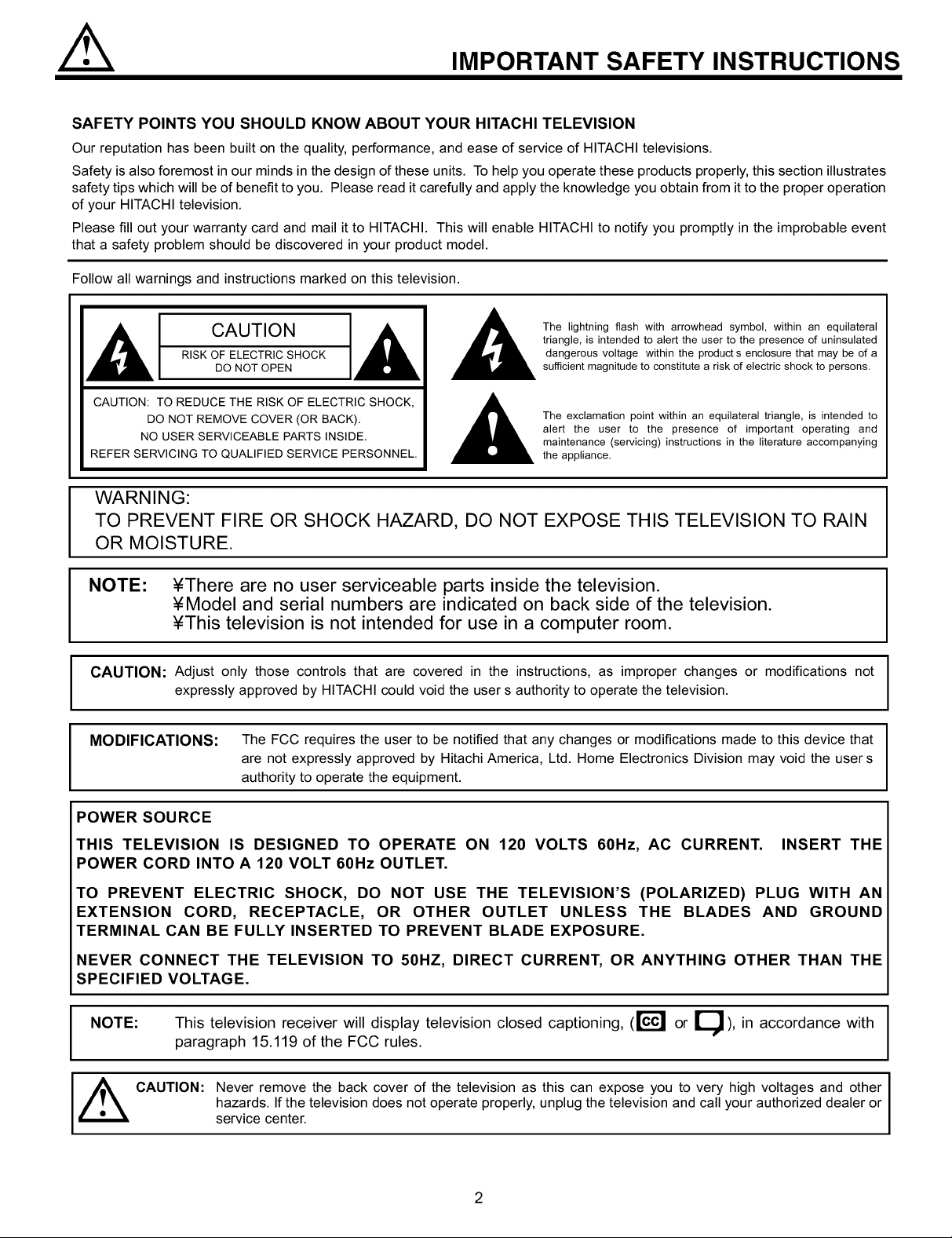
Follow all warnings and instructions marked on this television.
The lightning flash with arrowhead symbol, within an equilateral
IA[ C OTO IA!
RISK OF ELECTRIC SHOCK
DO NOT OPEN
triangle, is intended to alert the user to the presence of uninsulated
dangerous voltage within the products enclosure that may be of a
sufficient magnitude to constitute a risk of electric shock to persons.
CAUTION: TO REDUCE THE RISK OF ELECTRIC SHOCK,
DO NOT REMOVE COVER (OR BACK).
NO USER SERVICEABLE PARTS INSIDE.
REFER SERVICING TO QUALIFIED SERVICE PERSONNEL.
The exclamation point within an equilateral triangle, is intended to
alert the user to the presence of important operating and
maintenance (servicing) instructions in the literature accompanying
the appliance.
WARNING:
TO PREVENT FIRE OR SHOCK HAZARD, DO NOT EXPOSE THIS TELEVISION TO RAIN
OR MOISTURE.
NOTE: ¥There are no user serviceable parts inside the television.
¥Model and serial numbers are indicated on back side of the television.
¥This television is not intended for use in a computer room.
CAUTION: Adjust only those controls that are covered in the instructions, as improper changes or modifications not
expressly approved by HITACHI could void the user s authority to operate the television.
MODIFICATIONS: The FCC requires the user to be notified that any changes or modifications made to this device that
are not expressly approved by Hitachi America, Ltd. Home Electronics Division may void the user s
authority to operate the equipment.
POWER SOURCE
THIS TELEVISION IS DESIGNED TO OPERATE ON 120 VOLTS 60Hz, AC CURRENT. INSERT THE
POWER CORD INTO A 120 VOLT 60Hz OUTLET.
I
TO PREVENT ELECTRIC SHOCK, DO NOT USE THE TELEVISION'S (POLARIZED) PLUG WITH AN
EXTENSION CORD, RECEPTACLE, OR OTHER OUTLET UNLESS THE BLADES AND GROUND
TERMINAL CAN BE FULLY INSERTED TO PREVENT BLADE EXPOSURE.
NEVER CONNECT THE TELEVISION TO 50HZ, DIRECT CURRENT, OR ANYTHING OTHER THAN THE
SPECIFIED VOLTAGE.
NOTE: This television receiver will display television closed captioning, (lccl or _), in accordance with
paragraph 15.119 of the FCC rules.
[_ CAUTION: Never remove the back cover of the television as this can expose you to very high voltages and other
hazards. Ifthe television does not operate properly, unplug the television and call your authorized dealer or
service center.
2
#.
IMPORTANT SAFETY INSTRUCTIONS
Read before operating equipment
Follow all warnings and instructions marked on this
television.
1. Read these instructions.
2. Keep these instructions.
3. Heed all warnings.
4. Follow all instructions.
5. Do not use this apparatus near water.
6. Clean only with a dry cloth.
7. Do not block any ventilation openings. Install in
accordance with the manufacturer's instructions.
8. Do not install near any heat sources such as radiators,
heat registers, stoves, or other apparatus (including
amplifiers) that produce heat.
9. Do not defeat the safety purpose of the polarized or
grounding-type plug. A polarized plug has two blades
with one wider than the other. A grounding type plug
has two blades and a third grounding prong. The wide
blade or the third prong are provided for your safety. If
the provided plug does not fit into your outlet, consult
and electrician for replacement of the obsolete outlet.
10. Protect the power cord from being walked on or
pinched particularly at plugs, convenience
receptacles, and the point where they exit from the
apparatus.
11. Only use the attachments/accesories specified by the
manufacturer.
12.
Use only with the cart, stand, tripod,
15. Televisions are designed to comply with the
recommended safety standards for tilt and stability.
Do not apply excessive pulling force to the front, or
top, of the cabinet which could cause the product to
overturn resulting in product damage and/or personal
injury.
16. Follow instructions for wall, shelf or ceiling mounting
as recommended by the manufacturer.
17. An outdoor antenna should not be located in the
vicinity of overhead power lines or other electrical
circuits.
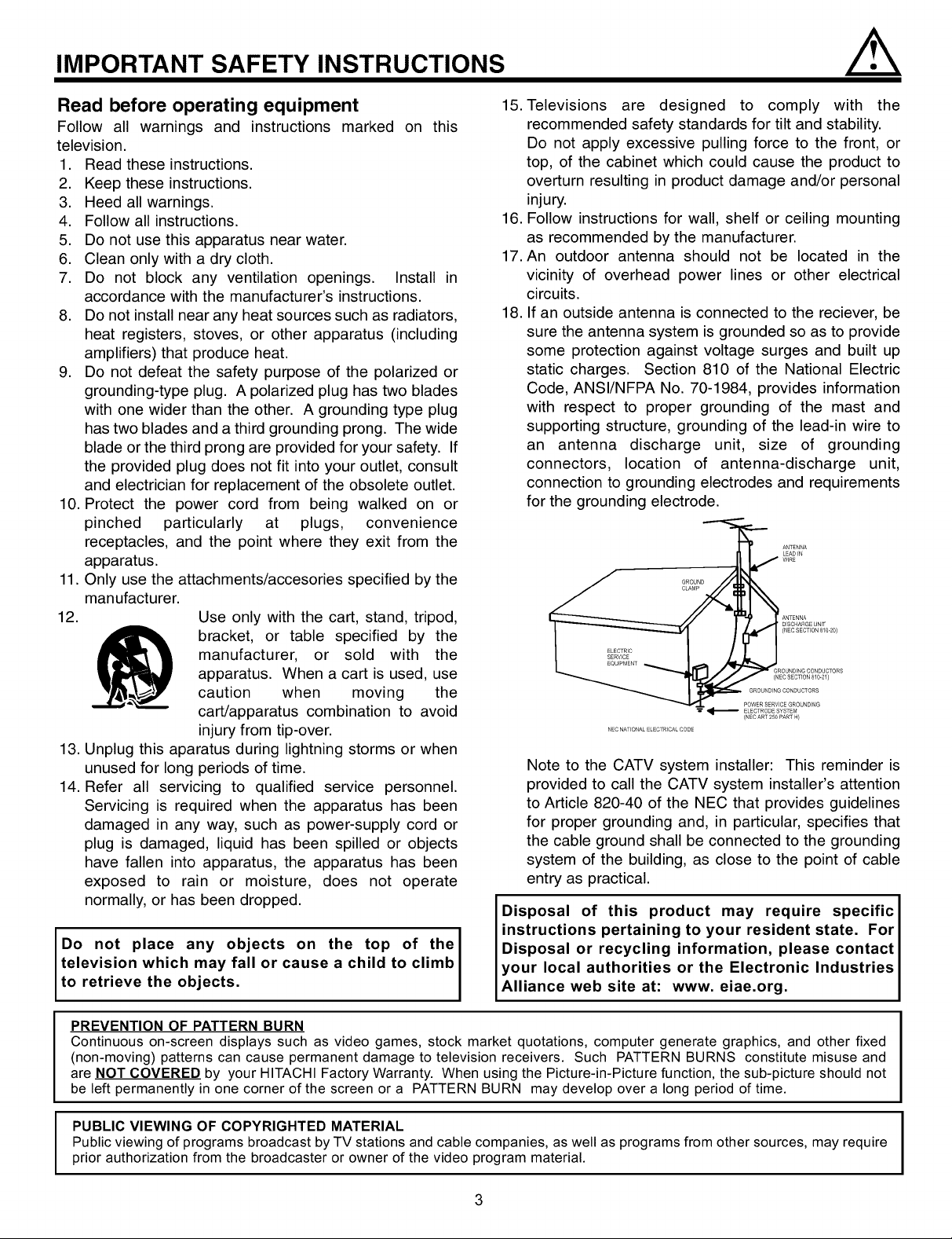
18. If an outside antenna is connected to the reciever, be
sure the antenna system is grounded so as to provide
some protection against voltage surges and built up
static charges. Section 810 of the National Electric
Code, ANSI/NFPA No. 70-1984, provides information
with respect to proper grounding of the mast and
supporting structure, grounding of the lead-in wire to
an antenna discharge unit, size of grounding
connectors, location of antenna-discharge unit,
connection to grounding electrodes and requirements
for the grounding electrode.
GROUND
CLAMP
manufacturer, or sold with the
apparatus. When a cart is used, use
bracket, or table specified by the
caution when moving the
cart/apparatus combination to avoid
injury from tip-over.
NEC NATfONAL ELECTRfCAL CODE
GROUND NGCONDUCTORS
POWER SERV CEGROUNDING
ELECTRODE SYSTEM
(NEC ART 250 PART H}
13. Unplug this aparatus during lightning storms or when
unused for long periods of time.
14. Refer all servicing to qualified service personnel.
Servicing is required when the apparatus has been
damaged in any way, such as power-supply cord or
plug is damaged, liquid has been spilled or objects
have fallen into apparatus, the apparatus has been
exposed to rain or moisture, does not operate
normally, or has been dropped.
Note to the CATV system installer: This reminder is
provided to call the CATV system installer's attention
to Article 820-40 of the NEC that provides guidelines
for proper grounding and, in particular, specifies that
the cable ground shall be connected to the grounding
system of the building, as close to the point of cable
entry as practical.
Disposal of this product may require specific
instructions pertaining to your resident state. For
Do not place any objects on the top of the
television which may fall or cause a child to climb
to retrieve the objects.
PREVENTION OF PATTERN BURN
Continuous on-screen displays such as video games, stock market quotations, computer generate graphics, and other fixed
(non-moving) patterns can cause permanent damage to television receivers. Such PATTERN BURNS constitute misuse and
are NOT COVERED by your HITACHI Factory Warranty. When using the Picture-in-Picture function, the sub-picture should not
be left permanently in one corner of the screen or a PATTERN BURN may develop over a long period of time.
Disposal or recycling information, please contact
your local authorities or the Electronic Industries
Alliance web site at: www. eiae.org.
PUBLIC VIEWING OF COPYRIGHTED MATERIAL
Public viewing of programs broadcast by TV stations and cable companies, as well as programs from other sources, may require
prior authorization from the broadcaster or owner of the video program material.
3
ACCESSORIES
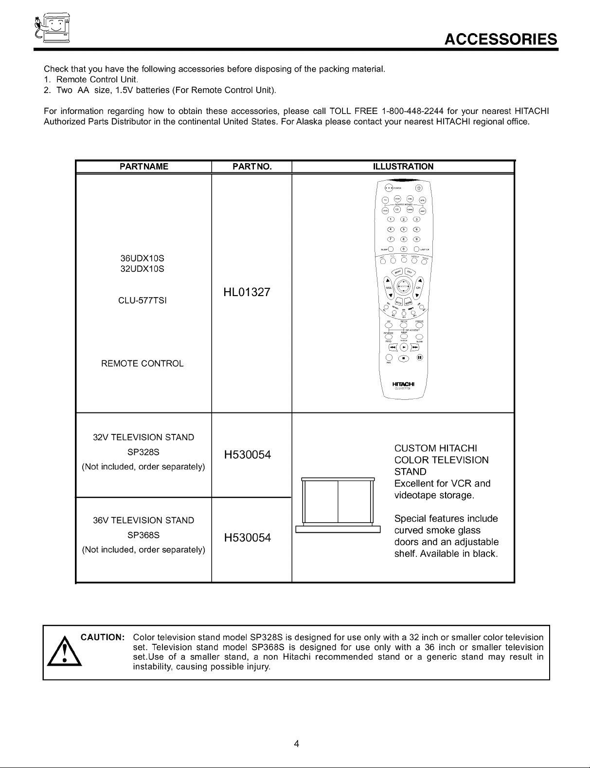
Check that you have the following accessories before disposing of the packing material.
1. Remote Control Unit.
2. Two AA size, 1.5V batteries (For Remote Control Unit).
For information regarding how to obtain these accessories, please call TOLL FREE 1-800-448-2244 for your nearest HITACHI
Authorized Parts Distributor in the continental United States. For Alaska please contact your nearest HITACHI regional office.
PARTNAME [ PARTNO. [ ILLUSTRATION
@...... @
(2b dO _
_b Q d_b
.... O _ O .....
36UDX10S
32UDX10S
CLU-577TSI
REMOTE CONTROL
32V TELEVISION STAND
SP328S
(Not included, order separately)
36V TELEVISION STAND
SP368S
(Not included, order separately)
HL01327
H530054
H530054
O O O
Odb®
HITAOHI
CUSTOM HITACHI
COLOR TELEVISION
STAND
Excellent for VCR and
videotape storage.
Special features include
curved smoke glass
doors and an adjustable
shelf. Available in black.
CAUTION:
Color television stand model SP328S is designed for use only with a 32 inch or smaller color television
set. Television stand model SP368S is designed for use only with a 36 inch or smaller television
set.Use of a smaller stand, a non Hitachi recommended stand or a generic stand may result in
instability, causing possible injury.
4
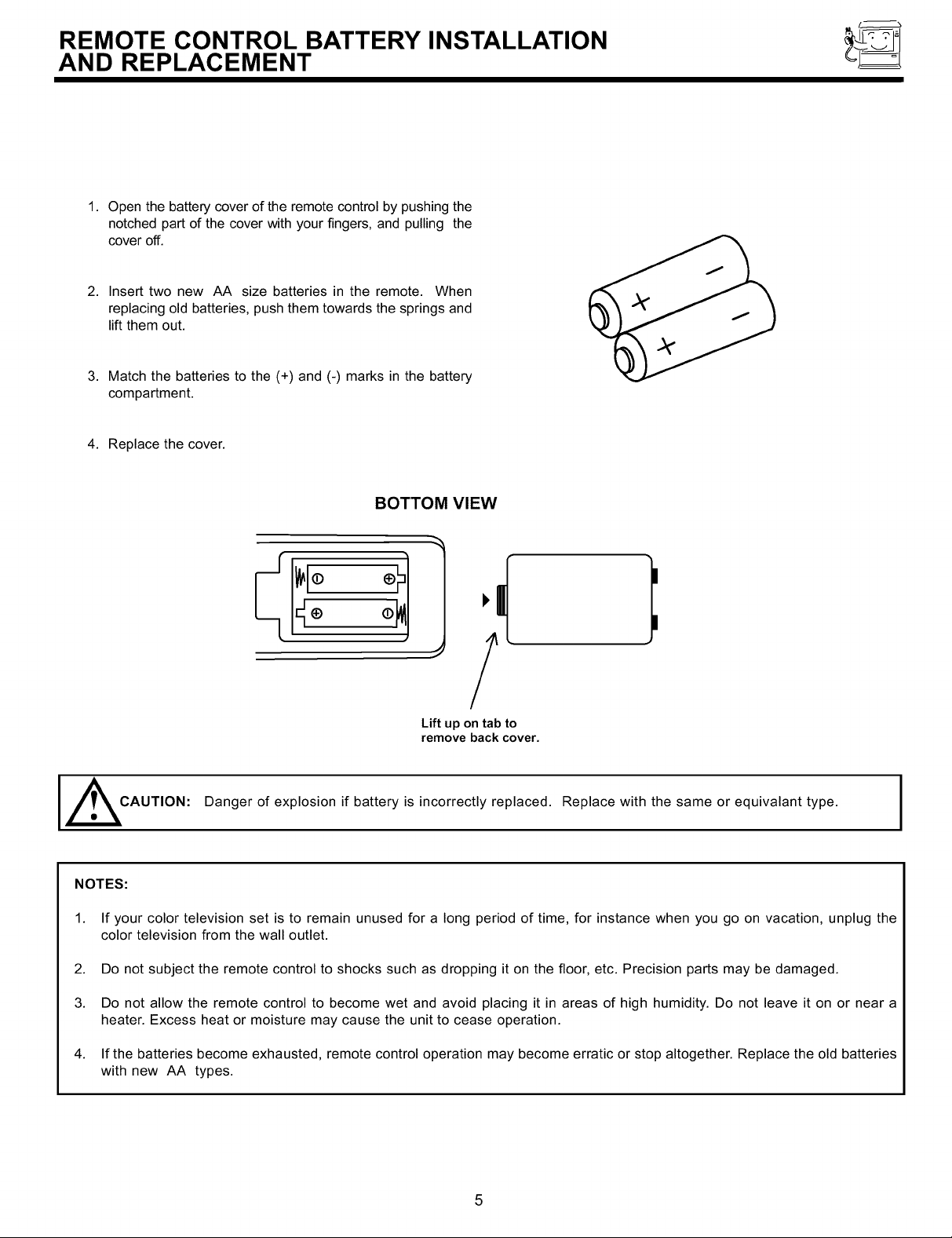
REMOTE CONTROL BATTERY INSTALLATION
AND REPLACEMENT
1.
Open the battery cover of the remote control by pushing the
notched part of the cover with your fingers, and pulling the
cover off.
2.
Insert two new AA size batteries in the remote. When
replacing old batteries, push them towards the springs and
lift them out.
3.
Match the batteries to the (+) and (-) marks in the battery
compartment.
4. Replace the cover.
BOTTOM VIEW
I,
Lift up on tab to
remove back cover.
CAUTION: Danger of explosion if battery is incorrectly replaced. Replace with the same or equivalant type. J
NOTES:
1. If your color television set is to remain unused for a long period of time, for instance when you go on vacation, unplug the
color television from the wall outlet.
2. Do not subject the remote control to shocks such as dropping it on the floor, etc. Precision parts may be damaged.
3. Do not allow the remote control to become wet and avoid placing it in areas of high humidity. Do not leave it on or near a
heater. Excess heat or moisture may cause the unit to cease operation.
4. If the batteries become exhausted, remote control operation may become erratic or stop altogether. Replace the old batteries
with new AA types.
5
HOW TO SET UP YOUR NEW
HITACHI COLOR TV
ANTENNA
Unless your color TV is connected to a cable TV system or to a centralized antenna system, a good outdoor color TV antenna is
recommended for best performance. However, if you are located in an exceptionally good signal area that is free from interference
and multiple image ghosts, an indoor antenna may be sufficient.
LOCATION
Select an area where sunlight or bright indoor illumination will not fall directly on the picture screen. Also, be sure that the location
selected allows a free flow of air to and from the back cover of the set.
To avoid cabinet warping, cabinet color changes, and increased chance of set failure, do not place the color TV where
temperatures can become excessively hot, for example, in direct sunlight or near a heating appliance, etc.
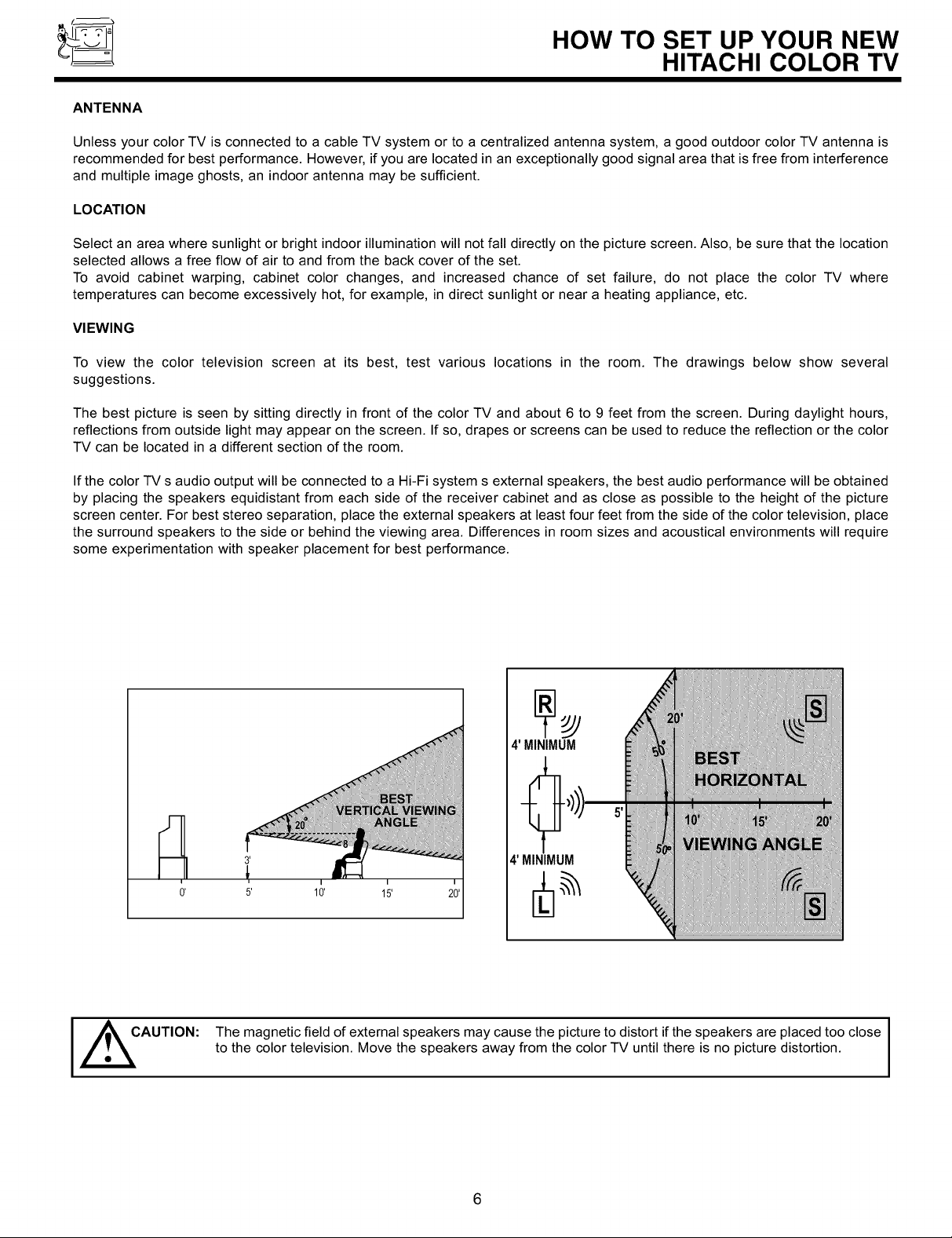
VIEWING
To view the color television screen at its best, test various locations in the room. The drawings below show several
suggestions.
The best picture is seen by sitting directly in front of the color TV and about 6 to 9 feet from the screen. During daylight hours,
reflections from outside light may appear on the screen. If so, drapes or screens can be used to reduce the reflection or the color
TV can be located in a different section of the room.
If the color TV s audio output will be connected to a Hi-Fi system s external speakers, the best audio performance will be obtained
by placing the speakers equidistant from each side of the receiver cabinet and as close as possible to the height of the picture
screen center. For best stereo separation, place the external speakers at least four feet from the side of the color television, place
the surround speakers to the side or behind the viewing area. Differences in room sizes and acoustical environments will require
some experimentation with speaker placement for best performance.
4' MINIMUM
4' MINIMUM
I _CAUTION: The magnetic field of external speakers may cause the picture to distort if the speakers are placed too close I
to the color television. Move the speakers away from the color TV until there is no picture distortion.
I
I
HOOK-UP CABLES AND CONNECTORS
Most video/audio connections between components can be made with shielded video and audio cables that have phono connectors.
For best performance, video cables should use 75-Ohm coaxial shielded wire. Cables can be purchased from most stores that sell
audio/video products. Below are illustrations and names of common connectors. Before purchasing any cables, be sure of the output
and input connector types required by the various components and the length of each cable.
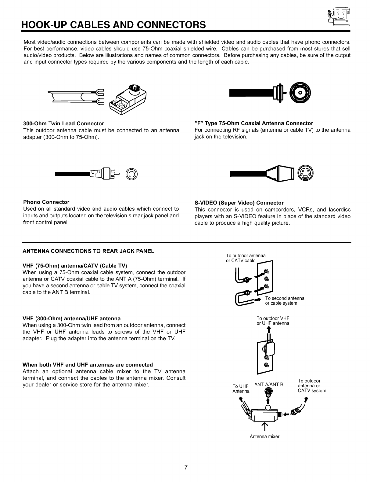
3O0-Ohm Twin Lead Connector
This outdoor antenna cable must be connected to an antenna
adapter (300-Ohm to 75-Ohm).
Phono Connector
Used on all standard video and audio cables which connect to
inputs and outputs located on the television s rear jack panel and
front control panel.
ANTENNA CONNECTIONS TO REAR JACK PANEL
VHF (75-Ohm) antenna/CATV (Cable TV)
When using a 75-Ohm coaxial cable system, connect the outdoor
antenna or CATV coaxial cable to the ANT A (75-Ohm) terminal. If
you have a second antenna or cable TV system, connect the coaxial
cable to the ANT B terminal.
"F" Type 75-Ohm Coaxial Antenna Connector
For connecting RF signals (antenna or cable TV) to the antenna
jack on the television.
@
S-VIDEO (Super Video) Connector
This connector is used on camcorders, VCRs, and laserdisc
players with an S-VIDEO feature in place of the standard video
cable to produce a high quality picture.
Tooutdoorantenna
or CATVcable
(_lp. TocSeb_ondsatnlenna
VHF (3O0-Ohm) antenna/UHF antenna
When using a 300-Ohm twin lead from an outdoor antenna, connect
the VHF or UHF antenna leads to screws of the VHF or UHF
adapter. Plug the adapter into the antenna terminal on the TV.
When both VHF and UHF antennas are connected
Attach an optional antenna cable mixer to the TV antenna
terminal, and connect the cables to the antenna mixer. Consult
your dealer or service store for the antenna mixer.
To outdoor VHF
or UHF antenna
Tooutdoor
ToUHF ANTA/ANT B antennaor
Antenna _ CATVsystem
¢
Antenna mixer
7
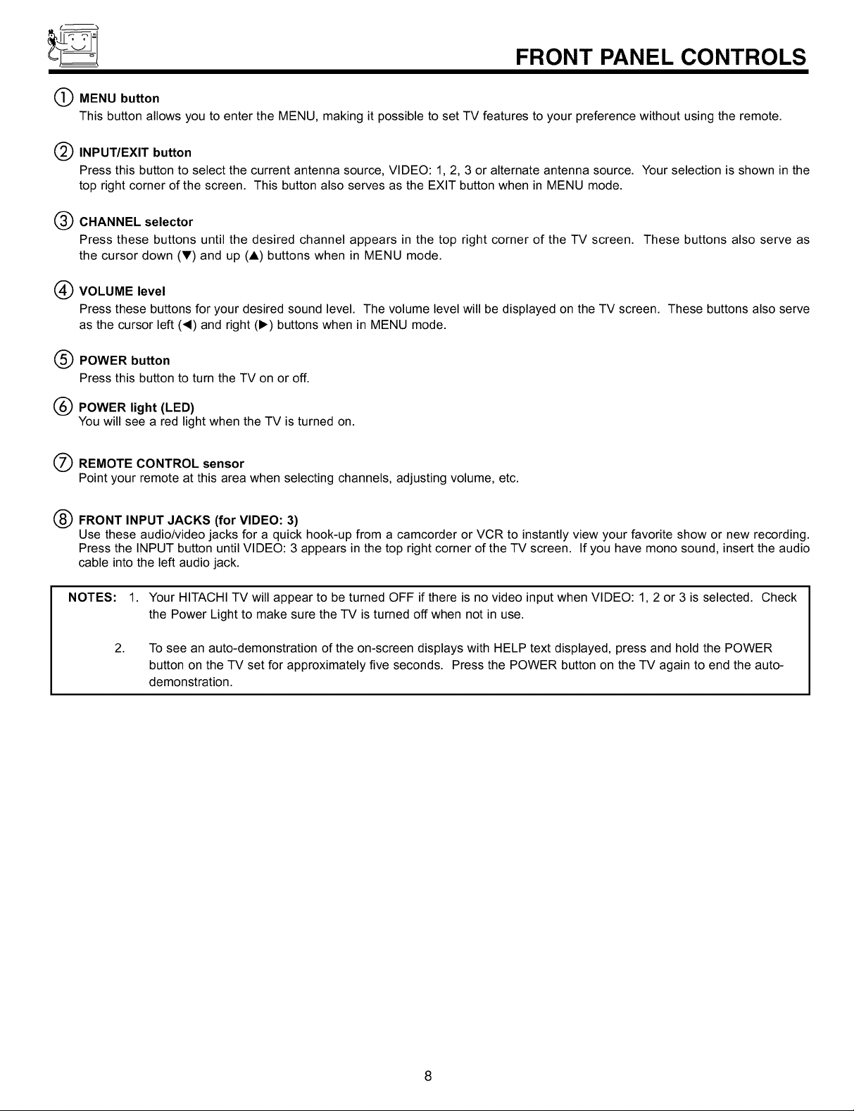
FRONT PANEL CONTROLS
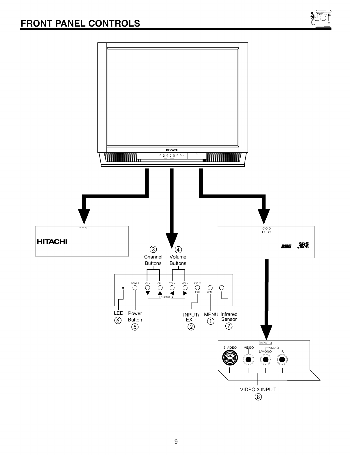
O MENU button
This button allows you to enter the MENU, making it possible to set TV features to your preference without using the remote.
Q INPUT/EXIT button
Press this button to select the current antenna source, VIDEO: 1, 2, 3 or alternate antenna source. Your selection is shown in the
top right corner of the screen. This button also serves as the EXIT button when in MENU mode.
(_) CHANNEL selector
Press these buttons until the desired channel appears in the top right corner of the TV screen. These buttons also serve as
the cursor down (V) and up (A) buttons when in MENU mode.
(_) VOLUME level
Press these buttons for your desired sound level. The volume level will be displayed on the TV screen. These buttons also serve
as the cursor left (_1) and right (1_) buttons when in MENU mode.
POWER button
®
Press this button to turn the TV on or off.
®
POWER light (LED)
You will see a red light when the TV is turned on.
O REMOTE CONTROL sensor
Point your remote at this area when selecting channels, adjusting volume, etc.
® FRONT INPUT JACKS (for VIDEO: 3)
Use these audio/video jacks for a quick hook-up from a camcorder or VCR to instantly view your favorite show or new recording.
Press the INPUT button until VIDEO: 3 appears in the top right corner of the TV screen. If you have mono sound, insert the audio
cable into the left audio jack.
NOTES: 1. Your HITACHI TV will appear to be turned OFF if there is no video input when VIDEO: 1, 2 or 3 is selected. Check
the Power Light to make sure the TV is turned off when not in use.
2.
To see an auto-demonstration of the on-screen displays with HELP text displayed, press and hold the POWER
button on the TV set for approximately five seconds. Press the POWER button on the TV again to end the auto-
demonstration.
FRONT PANEL CONTROLS
H_I
I I
HITACHI
® ®
Channel Volume
Buttons Buttons
¢]¢]
POWER CH CH + VOL VOL + INPUT
0 0 0 0 0 0 0 0
F]
LED Power
• • • _ ........ h
I ICURSOR_ I /
Button
®
/
INPUT/ MENU Infrared
EXIT @ Sensor
@ ®
_1 I I I
ooo
PUSH
V
FfiF07_
I L/MONO R
VIDEO 3 INPUT
®
9
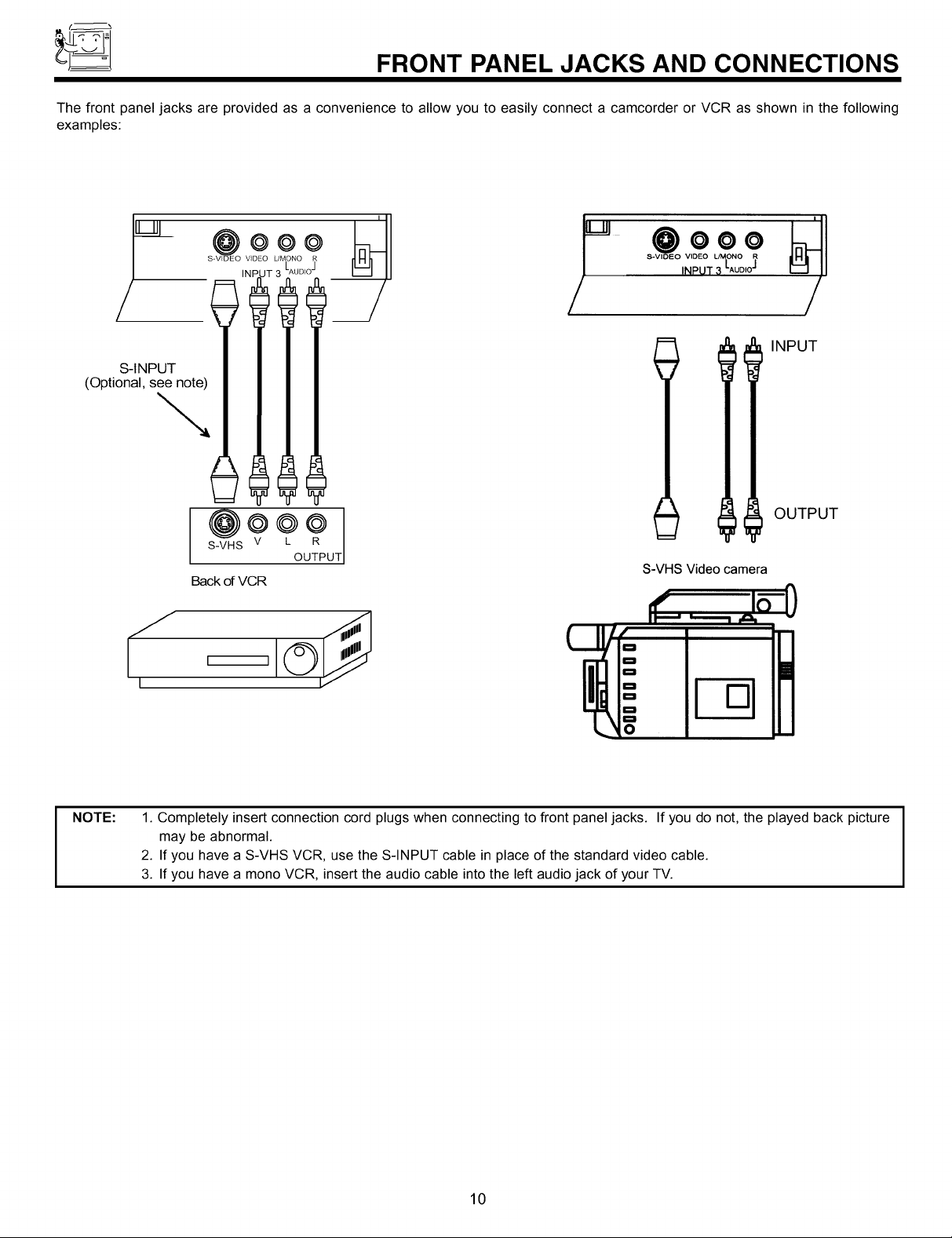
FRONT PANEL JACKS AND CONNECTIONS
The front panel jacks are provided as a convenience to allow you to easily connect a camcorder or VCR as shown in the following
examples:
v_2oO
JT 3 LAUDI°J
<o0tiona,1
@o@@
S-VHS V L R
Back of VCR
I I
[
'"' @ooo
_/ / /
INPUT
OUTPUT
OUTPUT
S-VHS Video camera
oS
NOTE:
1. Completely insert connection cord plugs when connecting to front panel jacks. If you do not, the played back picture
may be abnormal.
2. If you have a S-VHS VCR, use the S-INPUT cable in place of the standard video cable.
3. If you have a mono VCR, insert the audio cable into the left audio jack of your TV.
10
REAR PANEL JACKS
O ® ®
ANT A
TO
CONVERTER
rS-VIDE0
S-VIDE0 S-VIDE0
AUDIO
TOHI-FI j
ANT B
@
VIDEO
@
(MONO}<
AUDIO
INPUT 1 INPUT 2
@ @
@
AUDIO AUDIO
MONITOR
OUT
t t
® @ ®
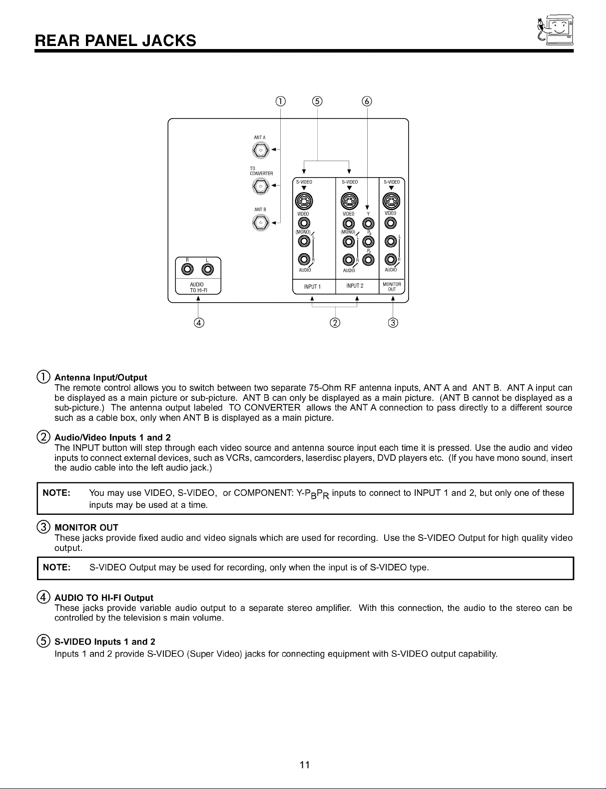
O Antenna Input/Output
The remote control allows you to switch between two separate 75-Ohm RF antenna inputs, ANT A and ANT B. ANT A input can
be displayed as a main picture or sub-picture. ANT B can only be displayed as a main picture. (ANT B cannot be displayed as a
sub-picture.) The antenna output labeled TO CONVERTER allows the ANT A connection to pass directly to a different source
such as a cable box, only when ANT B is displayed as a main picture.
Audio/Video Inputs 1 and 2
The INPUT button will step through each video source and antenna source input each time it is pressed. Use the audio and video
inputs to connect external devices, such as VCRs, camcorders, laserdisc players, DVD players etc. (If you have mono sound, insert
the audio cable into the left audio jack.)
NOTE: You may use VIDEO, S-VIDEO, or COMPONENT: Y-PBPR inputs to connect to INPUT 1 and 2, but only one of these I
inputs may be used at a time.
I
I
MONITOR OUT
These jacks provide fixed audio and video signals which are used for recording. Use the S-VIDEO Output for high quality video
output.
I NOTE: S-VIDEO Output may be used for recording, only when the input is of S-VIDEO type. I
(_ AUDIO TO HI-FI Output
These jacks provide variable audio output to a separate stereo amplifier. With this connection, the audio to the stereo can be
controlled by the television s main volume.
(_ S-VIDEO Inputs 1 and 2
Inputs 1 and 2 provide S-VIDEO (Super Video) jacks for connecting equipment with S-VIDEO output capability.
11
I
REAR PANEL JACKS
Q Component: Y-PBPR Input
Input 2 provides Y-PBPR jacks for connecting equipment with this capability, such as a DVD player or Set Top Box.
NOTES:
1. DO NOT connect standard VIDEO or S-VIDEO to Input 2 when using Y-PBPR input.
2. When using the Y-PBPR input jacks, connect your components audio output to the TV s Input 2 Left and Right Audio input jacks.
3. Your component output may be labeled Y, B-Y, and R-Y. In this case, connect the components B-Y output to the TV s PB input and
the components R-Y output to the TV s PR input.
4. Your component output may be labeled Y-CBC R. In this case, connect the component CB output to the TV s PB input and the
component CR output to the TVs PR input.
5. It may be necessary to adjust TINT to obtain optimum picture quality when using the Y-PBPR inputs. (See page 54)
6. To ensure no copyright infringement, the MONITOR OUT output will be abnormal, when using the Y-PBPR jacks.
7. When using the Y-PBPR jacks, PIP sub-picture can not be turned ON. It is not possible to view a Y-PBPR input while PIP is ON.
(See page 25)
12
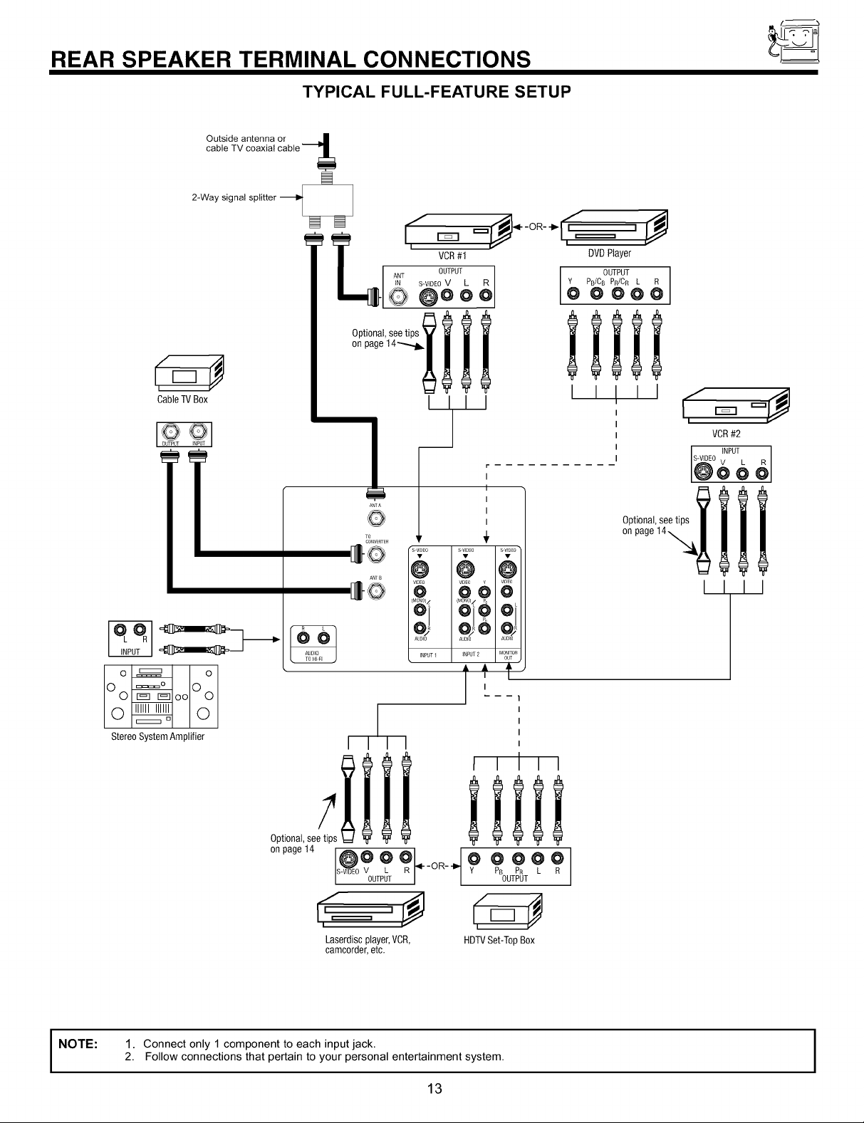
REAR SPEAKER TERMINAL CONNECTIONS
TYPICAL FULL-FEATURE SETUP
Cable TV Box
VCR#2
I INPUT
S-VIDEO V L
@oo_
Oo ooOo
Stereo System Amplifier
Optional,see tips
onpage14 @O O _R].4._OR_._ y_ _ _ p R_
I I I I
i i Ill
/
R-VIDEO V L PB PR
OUTPUT OUTPUT
Laserdisc player,VCR,
camcorder, etc.
lllll
HDTVSet-Top Box
I I I I
i
NOTE:
1. Connect only 1 component to each input jack.
2. Follow connections that pertain to your personal entertainment system.
13
I
TIPS ON REAR PANEL CONNECTIONS
TIPS ON REAR PANEL CONNECTIONS
S-VIDEO connections are provided for high performance laserdisc players, VCRs etc. that have this feature. Use these connections
in place of the standard video connection if your device has this feature.
If your device has only one audio output (mono sound), connect it to the left audio jack on the television.
Refer to the operating guide of your other electronic equipment for additional information on connecting your hook-up cables.
A single VCR can be used for VCR #1 and VCR #2, but note that a VCR cannot record its own video or line output (INPUT: 1 in the
example on page 14). Refer to your VCR operating guide for more information on line input-output connections.
You may use VIDEO, S-VIDEO, or COMPONENT: Y-PBPR inputs to connect to Input 2, but only one of these may be used at a
time.
Connect only 1 component (VCR, DVD player, camcorder, etc.) to each input jack.
COMPONENT: Y-PBPR connections are provided for high performance components, such as DVD players. Use these connections
in place of the standard video connection if your device has this feature.
When using the Y-PBPR input jack, connect your components audio output to the TV s Input 2 Left and Right Audio input jacks.
Your component outputs may be labeled Y, B-Y, and R-Y. In this case, connect the components B-Y output to the TV s Pb input
and the components R-Y output to the TV s PR input.
Your component outputs may be labeled Y-CBC R. In this case, connect the components CB output to the TV s PB input and the
components CR output to the TV s PR input.
It may be necessary to adjust TINT to obtain optimum picture quality when using the Y-PBPR inputs. (See page 54)
To ensure no copyright infringement, the MONITOR OUT output will be abnormal, when using the Y-PBPR jacks.
14
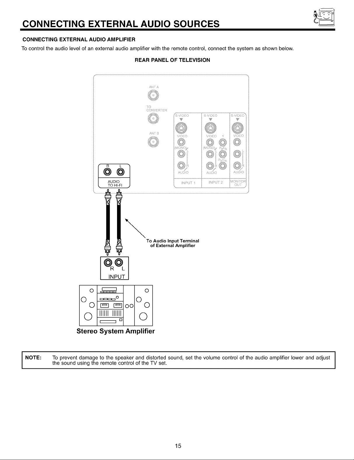
CONNECTING EXTERNAL AUDIO SOURCES
CONNECTING EXTERNAL AUDIO AMPLIFIER
To control the audio level of an external audio amplifier with the remote control, connect the system as shown below.
REAR PANEL OF TELEVISION
AN Y/\
°°1
AUDIO
• TO HI-FI
NOTE:
To Audio Input Terminal
of External Amplifier
INPUT
O _ O
0 ====° 0
0 r_lr_loo 0
Q ,llllllllll Q
Stereo System Amplifier
To prevent damage to the speaker and distorted sound, set the volume control of the audio amplifier lower and adjust I
the sound using the remote control of the TV set.
[]
I
I
15
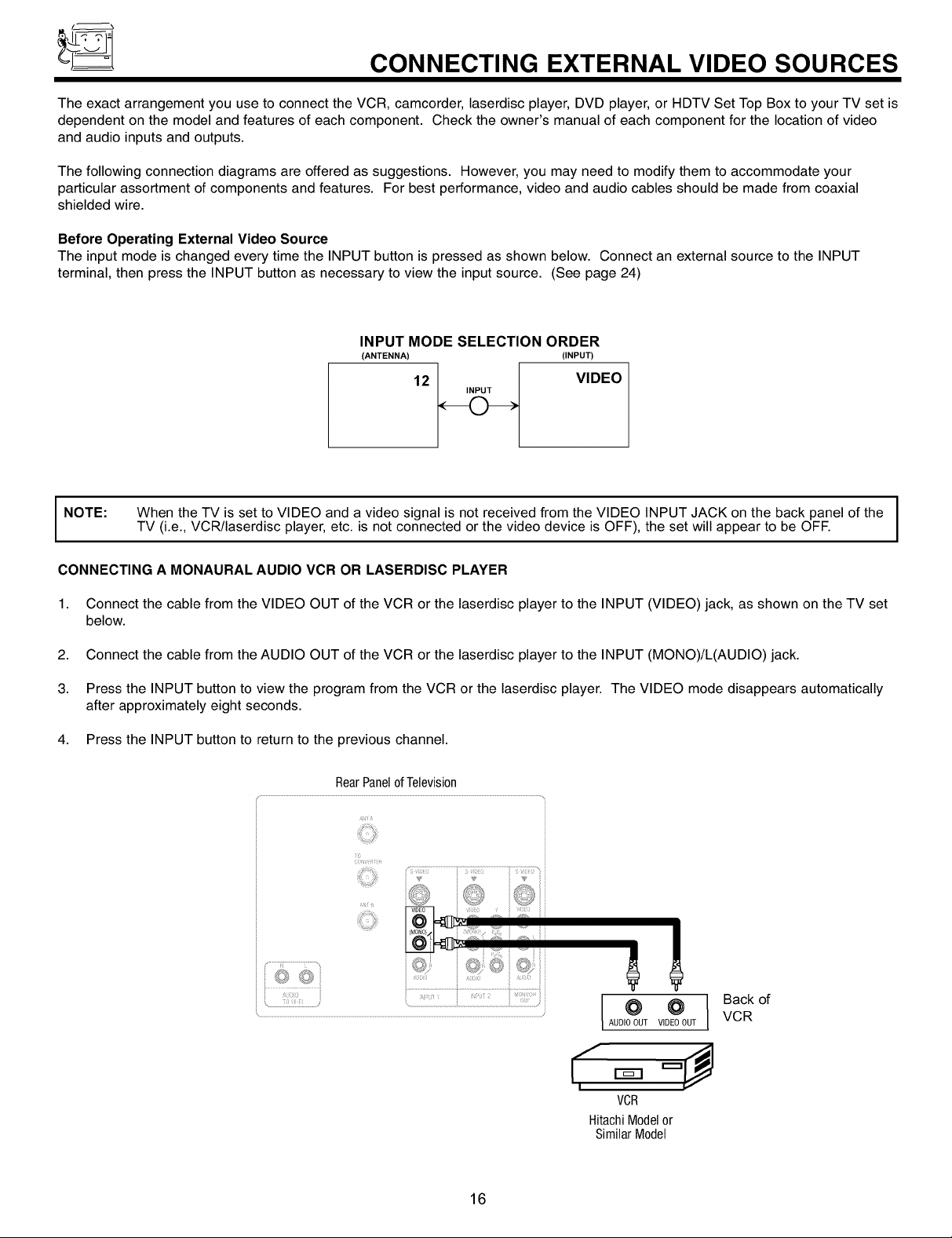
CONNECTING EXTERNAL VIDEO SOURCES
The exact arrangement you use to connect the VCR, camcorder laserdisc player, DVD player, or HDTV Set Top Box to your TV set is
dependent on the model and features of each component. Check the owner's manual of each component for the location of video
and audio inputs and outputs.
The following connection diagrams are offered as suggestions. However you may need to modify them to accommodate your
particular assortment of components and features. For best performance, video and audio cables should be made from coaxial
shielded wire.
Before Operating External Video Source
The input mode is changed every time the INPUT button is pressed as shown below. Connect an external source to the INPUT
terminal, then press the INPUT button as necessary to view the input source. (See page 24)
INPUT MODE SELECTION ORDER
(ANTENNA) (INPUT)
12
INPUT
VIDEO
NOTE:
CONNECTING A MONAURAL AUDIO VCR OR LASERDISC PLAYER
1. Connect the cable from the VIDEO OUT of the VCR or the laserdisc player to the INPUT (VIDEO) jack, as shown on the TV set
below.
2. Connect the cable from the AUDIO OUT of the VCR or the laserdisc player to the INPUT (MONO)/L(AUDIO) jack.
3. Press the INPUT button to view the program from the VCR or the laserdisc player. The VIDEO mode disappears automatically
after approximately eight seconds.
4. Press the INPUT button to return to the previous channel.
When the TV is set to VIDEO and a video signal is not received from the VIDEO INPUT JACK on the back panel of the I
TV (i.e., VCR/laserdisc player, etc. is not connected or the video device is OFF), the set will appear to be OFF.
i T
i©
I
I
16
Iool
AUDIOOUT VIDEOOUT
I I
VOR
HitachiModelor
SimilarModel
Back of
VCR
CONNECTING EXTERNAL VIDEO SOURCES
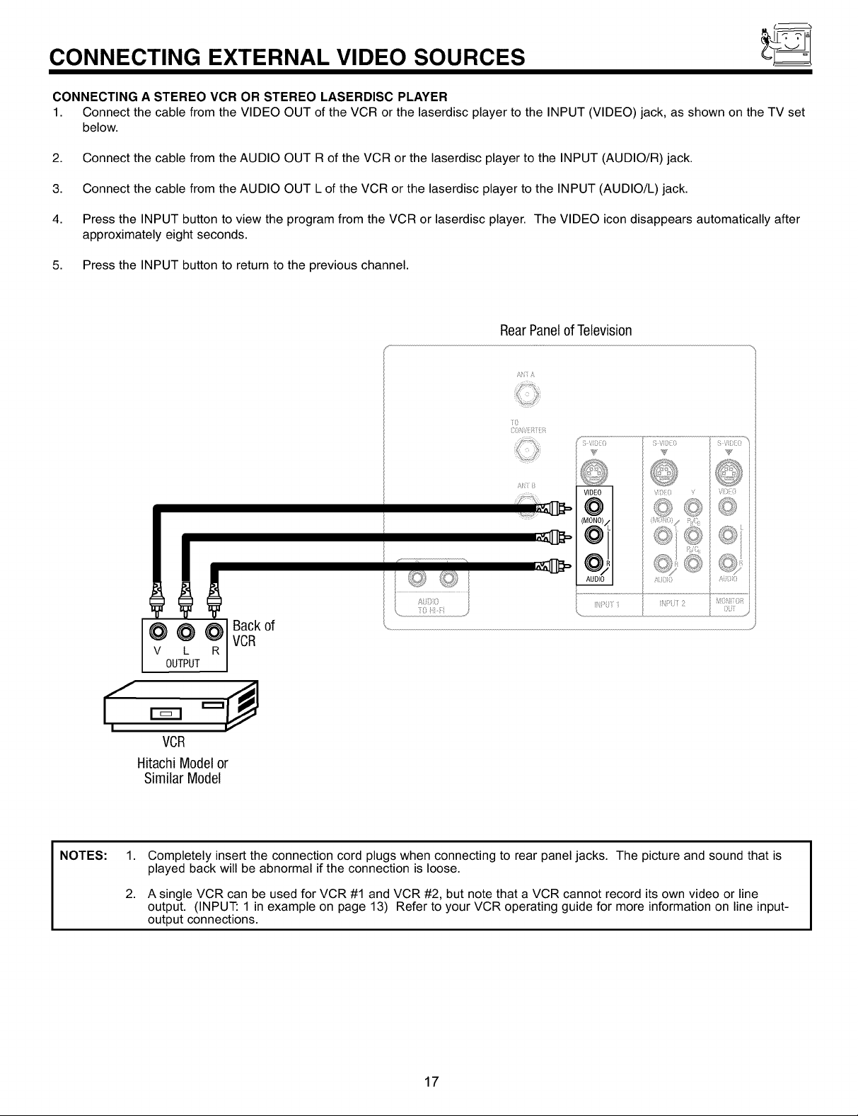
CONNECTING A STEREO VCR OR STEREO LASERDISC PLAYER
1. Connect the cable from the VIDEO OUT of the VCR or the laserdisc player to the INPUT (VIDEO) jack, as shown on the TV set
below.
2. Connect the cable from the AUDIO OUT R of the VCR or the laserdisc player to the INPUT (AUDIO/R) jack.
3. Connect the cable from the AUDIO OUT L of the VCR or the laserdisc player to the INPUT (AUDIO/L) jack.
4. Press the INPUT button to view the program from the VCR or laserdisc player. The VIDEO icon disappears automatically after
approximately eight seconds.
5. Press the INPUT button to return to the previous channel.
RearPanelof Television
(
.......................................:i ......................................
I",
NOTES: 1.
/[ ?? Z: ?)
l?J>O ;4i N )2
Lk
@VOUTPUT@L _RI vCRBaCkof
)
VCR
Hitachi Modelor
Similar Model
Completely insert the connection cord plugs when connecting to rear panel jacks. The picture and sound that is
played back will be abnormal if the connection is loose.
2.
A single VCR can be used for VCR #1 and VCR #2, but note that a VCR cannot record its own video or line
output. (INPUT: 1 in example on page 13) Refer to your VCR operating guide for more information on line input-
output connections.
17

CONNECTING EXTERNAL VIDEO SOURCES
CONNECTING AN S-VIDEO VCR OR LASERDISC PLAYER
1. Connect the cable from the S-VIDEO OUT of the VCR or the laserdisc player to the INPUT (S-VIDEO) jack, as shown on the TV
set below.
2. Connect the cable from the AUDIO OUT R of the VCR or the laserdisc player to the INPUT (AUDIO/R) jack.
3. Connect the cable from the AUDIO OUT L of the VCR or the laserdisc player to the INPUT (AUDIO/L) jack.
4. Press the INPUT button to view the program from the VCR or laserdisc player. The VIDEO icon disappears automatically after
approximately eight seconds.
5. Press the INPUT button to return to the previous channel.
RearPanelofTelevision
£_4i £
Seetips on
Page 14
Back of
VCR
NOTES: 1.
; Vii
S \iS)L{i I 5 iiii}{i{i
@il
I
v L
¢¢?
OUTPUT
VCR or Laserdisc Player
Hitachi Model or
Similar Model
Completely insert the connection cord plugs when connecting to rear panel jacks. The picture and sound that is
played back will be abnormal if the connection is loose.
2.
A single VCR can be used for VCR #1 and VCR #2, but note that a VCR cannot record its own video or line
output. (INPUT: 1 in example on page 13) Refer to your VCR operating guide for more information on line input-
output connections.
¢'1:'
A[0
18
CONNECTING EXTERNAL VIDEO SOURCES
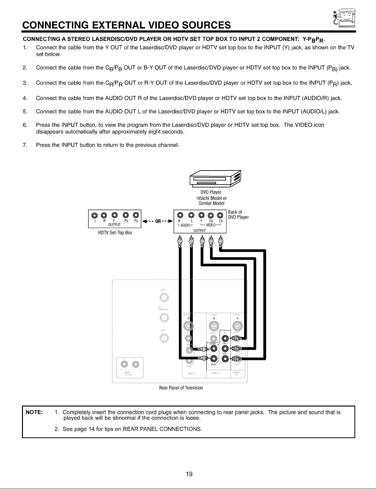
CONNECTING A STEREO LASERDISC/DVD PLAYER OR HDTV SET TOP BOX TO INPUT 2 COMPONENT: Y-PBPR .
1. Connect the cable from the Y OUT of the Laserdisc/DVD player or HDTV set top box to the INPUT (Y) jack, as shown on the TV
set below.
2. Connect the cable from the CB/P B OUT or B-Y OUT of the Laserdisc/DVD player or HDTV set top box to the INPUT (PB) jack.
3. Connect the cable from the CR/P R OUT or R-Y OUT of the Laserdisc/DVD player or HDTV set top box to the INPUT (PR) jack.
4. Connect the cable from the AUDIO OUT R of the Laserdisc/DVD player or HDTV set top box to the INPUT (AUDIO/R) jack.
5. Connect the cable from the AUDIO OUT L of the Laserdisc/DVD player or HDTV set top box to the INPUT (AUDIO/L) jack.
6. Press the INPUT button, to view the program from the Laserdisc/DVD player or HDTV set top box. The VIDEO icon
disappears automatically after approximately eight seconds.
7. Press the INPUT button to return to the previous channel.
DVDPlayer
HitachiModelor
SimilarModel
Backof
L R Y PB PR _1--- OR R L Y CB CR
OUTPUT LAUDIOJ L-- VlDEO_
@@ @ @ @1 @ @ @@@
HDTVSet-T0pBox OUTPUT
DVDPlayer
NOTE:
1. Completely insert the connection cord plugs when connecting to rear panel jacks. The picture and sound that is
played back will be abnormal if the connection is loose.
2. See page 14 for tips on REAR PANEL CONNECTIONS.
19
_0 SYSTEM SETUP
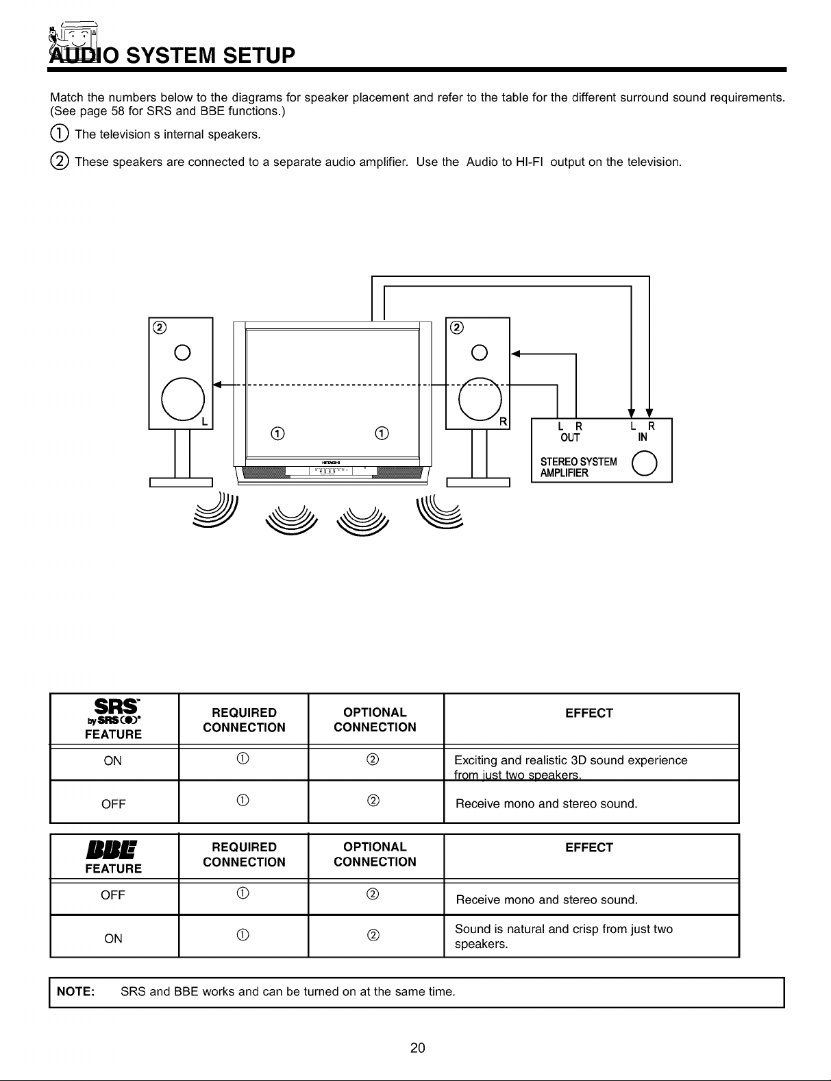
Match the numbers below to the diagrams for speaker placement and refer to the table for the different surround sound requirements.
(See page 58 for SRS and BBE functions.)
The television s internal speakers.
These speakers are connected to a separate audio amplifier. Use the Audio to HI-FI output on the television.
I
®
®
O
0 <
q I 'r ,'
q-
(9 (9
I
3
SRS" REQUIRED OPTIONAL EFFECT
bySRS¢O)" CONNECTION CONNECTION
FEATURE
L R L R
OUT IN
STEREOSYSTEM @
AMPLIFIER
ON (D (_) Exciting and realistic 3D sound experience
OFF (_) (_) Receive mono and stereo sound.
RR___" REQUIRED OPTIONAL EFFECT
FEATURE
OFF (_) (_) Receive mono and stereo sound.
ON (_) (_) Sound is natural and crisp from just two
I NOTE: SRS and BBE works and can be turned on at the same time.
CONNECTION CONNECTION
20
from iust two soeakers.
speakers.
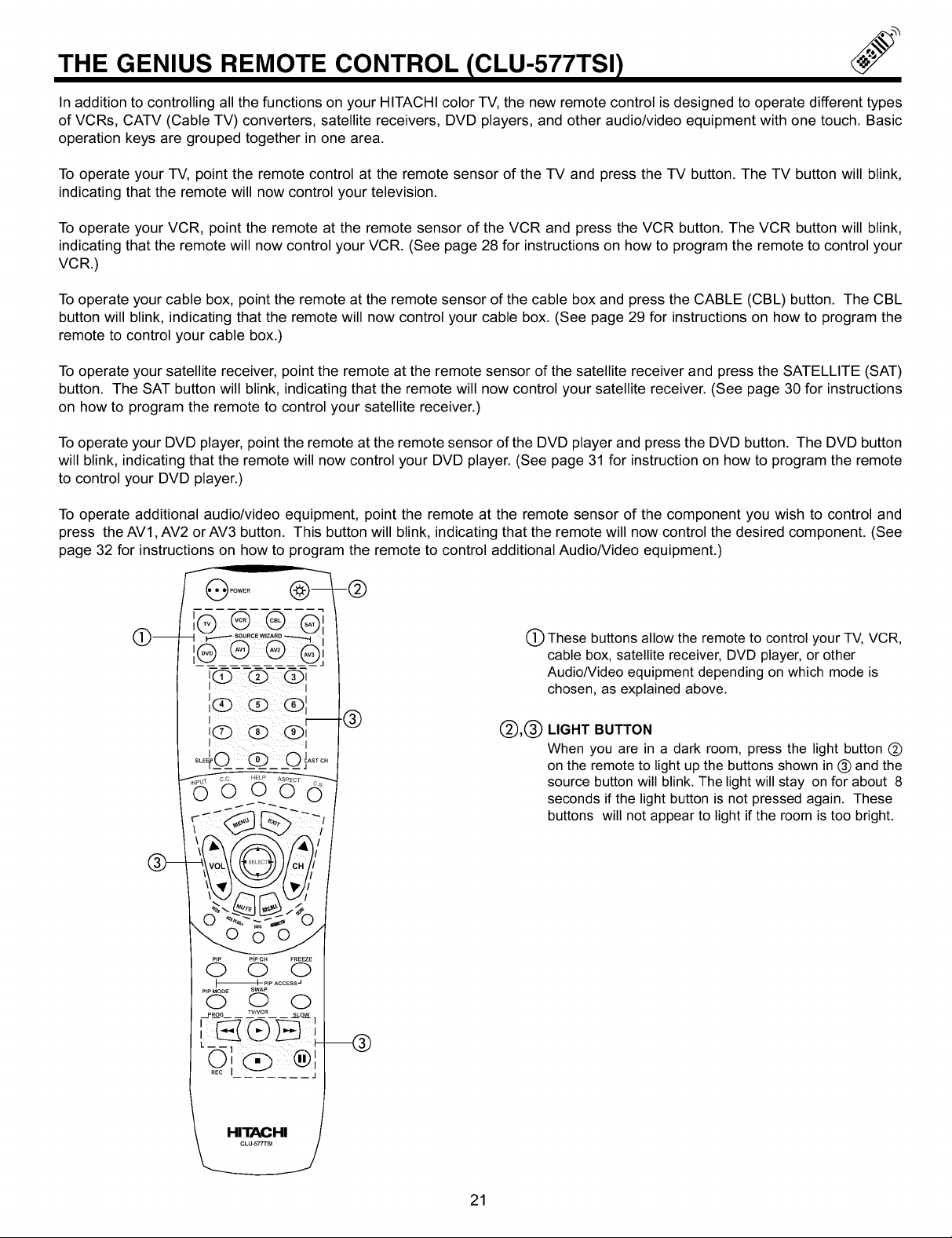
THE GENIUS REMOTE CONTROL ICLU-577TSI)
In addition to controlling all the functions on your HITACHI color TV, the new remote control is designed to operate different types
of VCRs, CATV (Cable TV) converters, satellite receivers, DVD players, and other audio/video equipment with one touch. Basic
operation keys are grouped together in one area.
To operate your TV, point the remote control at the remote sensor of the TV and press the TV button. The TV button will blink,
indicating that the remote will now control your television.
To operate your VCR, point the remote at the remote sensor of the VCR and press the VCR button. The VCR button will blink,
indicating that the remote will now control your VCR. (See page 28 for instructions on how to program the remote to control your
VCR.)
To operate your cable box, point the remote at the remote sensor of the cable box and press the CABLE (CBL) button. The CBL
button will blink, indicating that the remote will now control your cable box. (See page 29 for instructions on how to program the
remote to control your cable box.)
To operate your satellite receiver, point the remote at the remote sensor of the satellite receiver and press the SATELLITE (SAT)
button. The SAT button will blink, indicating that the remote will now control your satellite receiver. (See page 30 for instructions
on how to program the remote to control your satellite receiver.)
To operate your DVD player, point the remote at the remote sensor of the DVD player and press the DVD button. The DVD button
will blink, indicating that the remote will now control your DVD player. (See page 31 for instruction on how to program the remote
to control your DVD player.)
To operate additional audio/video equipment, point the remote at the remote sensor of the component you wish to control and
press the AV1, AV2 or AV3 button. This button will blink, indicating that the remote will now control the desired component. (See
page 32 for instructions on how to program the remote to control additional Audio/Video equipment.)
(_) These buttons allow the remote to control your TV, VCR,
cable box, satellite receiver, DVD player, or other
Audio/Video equipment depending on which mode is
chosen, as explained above.
(_),(_) LIGHT BUTTON
When you are in a dark room, press the light button (_)
on the remote to light up the buttons shown in (_) and the
source button will blink. The light will stay on for about 8
seconds if the light button is not pressed again. These
buttons will not appear to light if the room is too bright.
21
 Loading...