

Page 1
SOLID STATE COLOR TV
OPERATING GUIDE
IMPORTANT SAFEGUARDS
FIRST TIME USE
THE REMOTE CONTROL
EASY GRAPHIC GUIDE
2-5
6-23
24-40
41 - 60
==m)ff y
USEFUL INFORMATION
INDEX
61 -66
Page 2
IMPORTANT
Yournew HITACHICOLOfl TV incoqxxah_ a hostoffealuresdemigned_ giveyouexxxdienl_ J _ _
me _ in this ..znu_ We _ ezazyou read Ozef_k]minginsZmc_ns and _ANT SAFE-
GUAFO)S"notice_ fumingON yourTV set forIhe lusttme.
F(i:pwall m and _ m;zdmdonthisZegeviskmreceiver.
,_ RISKOF ELECTFIK_SHOCX
CAUTION:TO REXXICETHE RISK OF _ _
_ SERUIICmGTO GIUNJIFII3D_ _
I
I CAUTION
NO _ PARIS INSIDE.
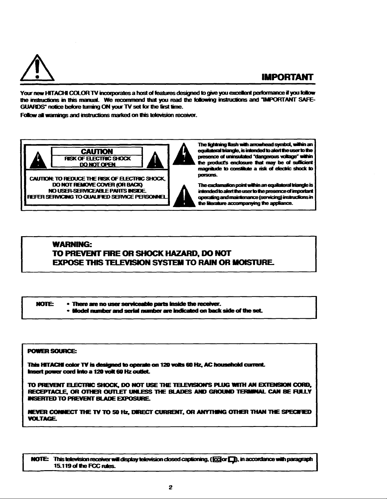
WARNING:
TO FgEVB(I" FIRE OR SHOCK HAZARD, DO NOT
EXPOSE TillS TELEVISION SYSTEM TO RAIN OR MOISTURE.
NOTE=
IX) NOTOPEN
• There are no user sermiceal_ pints kmide lhe receive.
- Model mmnl)m"and serial number are k_licaled onback side of Um set.
mnsm_dIoatedlhe mert)_e pmsm_ d W
q_armgand___s_c_mi.
I
POWEStS(XJlK_
Tlds i,HTIK_HI color W is deaigned b operale on 120 volts 60 az, AC _ cialanL
Inse4 i)omer coni bto a 120 volt 60 Hz oullet.
TO _ _ SIIOCI(. IX) NOT U_ "lrl-E11_EVlSlO14"SPLUG WlIH AN _ CORO,
_ACLE, OR _ OUTLET UILJE_S THE BLADES ANO _qP0Ul_ 11E]FIMNAL CAN I_E i:ULLY
INSaTI1E_ TO _ BL4JDE EXPOSUR_
NL:Vt_ _ TI_ IV TO 50 Hz, DIRECT CtmR_IT, OR ANYllglNG _ 11tAN THE _
VIXTkGF_
15.119 of OzeFCC
2
Page 3
SAFETY TIPS
IMPORTANT SAFEGUARDS
SAFETY POINTS YOU SHOULD KNOW ABOUT
YOUR HITACHI TELEVISION RECEIVER
Our reputation has been built on the quality, performance, and ease of service of HITACHI television receivers.
Safety is also foremost in our minds in the design of these units. To help you operate these products properly, this folder illustrates safety tips which will be of benefit
to you. Please read it carefully and apply the Knowledge you obtain from it to the proper operation of your HITACHI television receiver.
Please fill out your warranty card at once and mail it to HITACHI. This will enable HITACHI to notify you promptly in the improbable event that a safety problem should
be discovered in your model of product.
CAUTION:
* Read alloftheseinstructions
* Save these instructionsfor lateruse.
* Followallwamingsand instructionsmarked
on the television receiver.
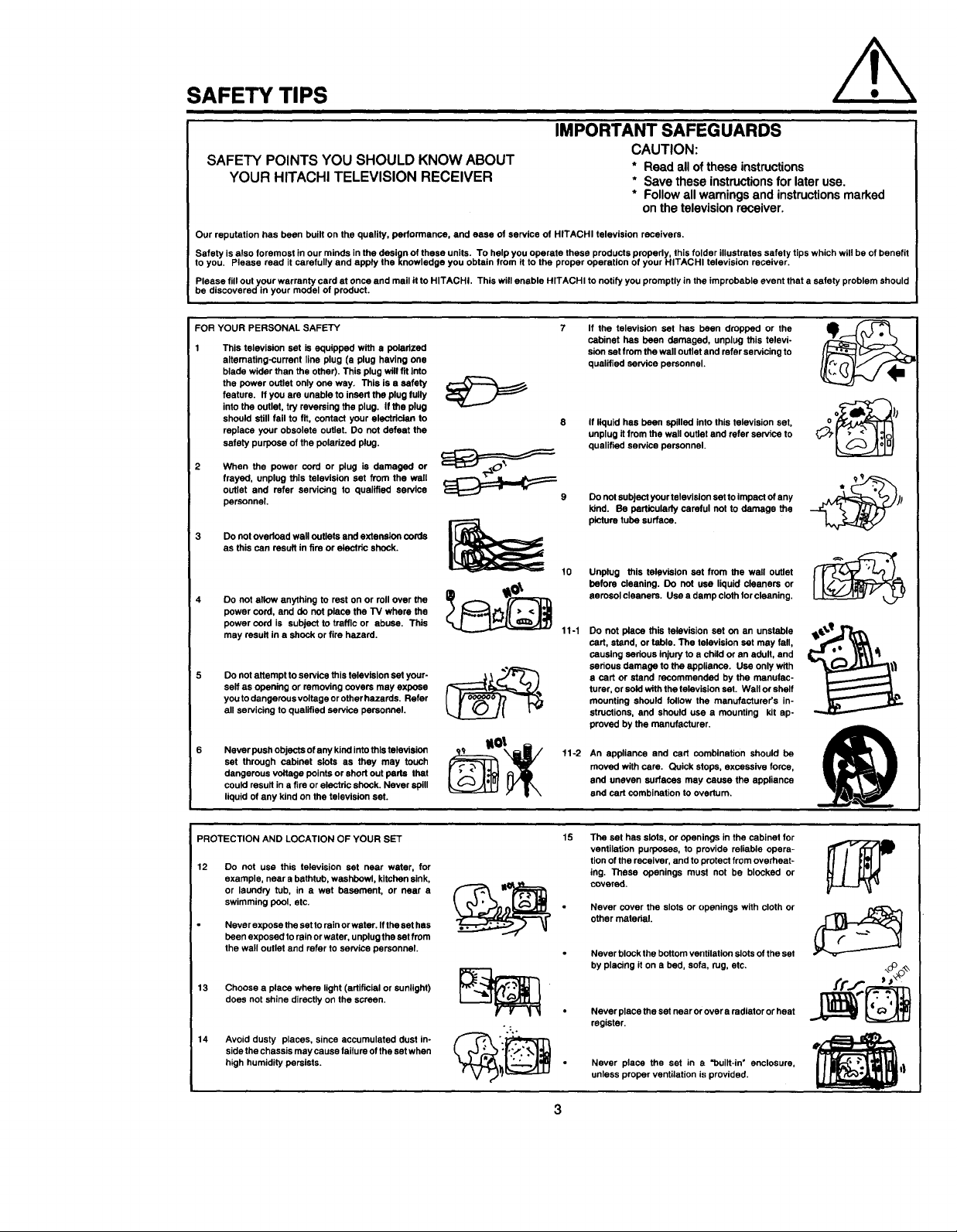
FOR YOUR PERSONAL SAFETY
This television set is equipped with a poladzed
altemating-currant line plug (a plug having one
blade wider than the other). This plug will fit Into
the power outlet only one way. This is s safety
feature. If you are unable to insert the plug fully
into the outlet, try reversing the plug. If the plug
should still fail to fit, contact your electrician to
replace your obsolete outlet. Do not defeat the
safety purpose of the polarized plug.
When the power cord or plug is damaged or
frayed, unplug this television set from the wall
outlet and refer servicing to qualified service
personnel.
3 Do not ovedoed wall outlets and extension cords
as this can result in fire or elaotdc shock.
Do not allow anything to rest on or roll over the
power cord, and de not place the TV where the
power cord is subject to traffic or abuse. This
may result in a shock or fire hazard.
Do not attempt to service this television sst your-
serf as opening or removing covers may expose
you to dangerous voltage or other hazards. Refer
all servicing to qualified service personnel.
Never push objects of any kind into this television
set through cabinet slots as they may touch
dangerous voltage points or short out parts that
could result in a fire or electric shock. Never spill
liquid of any kind on the television set.
If the television set has been dropped or the
cabinet has been damaged, unplug this televi-
sion set from the wall outlet and refer servicing to
qualified service personnel.
if liquid has been spilled into this television set,
unplug it from the wall outlet and refer service to
qualified service personnel.
_9
Do not subject your television set to impact of any
kind. Be particularly careful not to damage the
picture tube surface.
Unplug this television set from the wall outlet
before cleaning. Do not use liquid cleaners or
aerosol cleaners. Use a damp cloth for cleaning.
11-1
Do not place this television set on an unstable
cart, stand, or table. The television set may fall,
causing sedous injury to a child or an adult, and
serious damage to the appliance. Use only with
a cart or stand recommended by the manufac-
turer, or sold with the television set. Wall or shelf
mounting should follow the manufacturer's in-
structions, and should use a mounting kit ap-
proved by the manufacturer.
11-2
An appliance and cart combination should be
moved with care. Quick stops, excessive force,
and uneven surfaces may cause the appliance
and cart combination to overturn.
PROTECTION AND LOCATION OF YOUR SET
12 Do not usa this television set near water, for
example, near a bathtub, washbowl, kitchen sink,
or laundry tub, in a wet basement, or near a
swimming pool, etc.
Never expose the set to rain or water. If the set has
been exposed to rain or water, unplug the set from
the wall outlet and refer to service personnel.
13 Choose a place where light (artificial or sunlight)
does not shine directly on the screen.
14 Avoid dusty places, since accumulated dust in-
side the chassis may cause failure of the set when
high humidity persists.
15
The set has slots, or openings in the cabinet for
ventilation purposes, to provide reliable opera-
tion of the receiver, and to protect from overheat-
ing. These openings must not be blocked or
covered.
Never cover the slots or openings with cloth or
other mstedal.
Never block the bottom ventilation slots of the set
by placing it on a bed, sofa, rug, etc.
Never place the set near or over a radiator or heat
register.
Never place the set in a "built-in" enclosure,
unless proper ventilation is provided.
Page 4
SAFETY TIPS
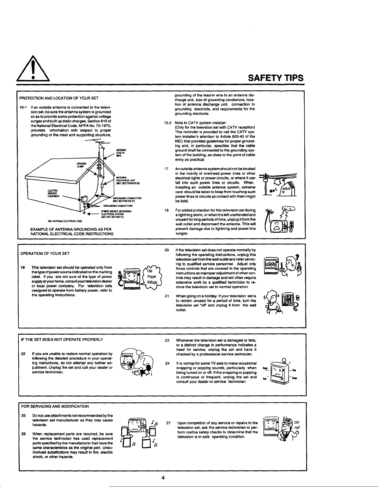
PROTL:CTION AND LOCATION OF YOUR SET
16-1 If an outside antenna is connected to the televi-
sion set, be sure the antenna system is grounded
so as to provide some protection against voltage
surges and built up static charges, Section 810 of
the National Elestrical Code, NFPA No. 70-1975,
provides information with respect to proper
!;]rounding of the mast and supporting structure,
EQU_=UEm
NECNAllONN.E_CTRICALCOtE
EXAMPLE OF ANTENNA GROUNDING AS PER
NATIONAL ELECTRICAL CODE INSTRUCTIONS
OPERATION OF YOUR SET
19
This television set should be operated only from
the type of power soume indicated on the marking
label. If you are not sure of the type of power
supply at your home, consult your television dealer
or local power company. For television sets
designed to operate from battery power, refer to
the operating instructions.
(NEC ART 250 P/Cq_l"HI
mRE
_SCHARGE UNIT
SECTION 810-20)
6_t0UNDINg
grounding of the lead-in wire to an antenna dis-
charge unit, size of grounding conductors, loca-
tion of antenna discharge unit, connection to
grounding electrode, and requirements for the
grounding electrode.
16-2
Note to CATV system installer:
(Only for the television set with CATV reception)
This reminder is provided to call the CATV sys-
tem installer's attention to Article 820-40 of the
NEC that provides guidelines for proper ground-
ing and, in particular, specifies that the cable
ground shall be connected to the grounding sys-
tem of the building, as close to the point of cable
entry as practical.
17
An outside antenna system should not be located
in the vicinity of overhead power lines or other
electrical lights or power circuits, or where it can
fall into such power lines or circuits. When
installing an outside antenna system, extreme
care should be taken to keep from touching such
power lines or circuifs as contact with them might
be fatal.
18
For added protection for this television set during
a lightning storm, or when it Is left unattended and
unused for long pedods of time, unplug it from the
wall outlet and disconnect the antenna. This will
prevent damage due to lightning and power-line
surges.
2O
If the television set does not operate normally by
following the operating instructions, unplug this
television set from the wall outlet and refer servic-
ing to qualified service personnel. Adjust only
those controls that are covered in the operating
instructions as improper adjustment of other con-
trols may result in damage and will often require
extensive work by a qualified technician to re-
store the television set to normal operation.
21
When going on a holiday: If your television set is
to remain unused for a pedod of time, turn the
television set "off' and unplug it from the wall
outlet.
IF THE SET DOES NOT OPERATE PROPERLY
22
If you are unable to restore normal operation by
following the detailed procedure in your operat-
ing instructions, do not attempt any further ad-
jtJ,stment. Unplug the set and call your dealer or
service technician.
FOR SERVICING AND MODIFICATION
25 Do not use attachments not recommended by the
television set manufacturer as they may cause
h_tzards.
26 When replacement parts are required, be sure
the service technician has used replacement
parts specified by the manufacturer that have the
sarne ctmrectedstics as the original part. Unau-
thorized substitutions may result in fire, electric
shock, or other hazards,
23
Whenever the television set is damaged or fails,
or a distinct change in performance indicates a
need for service, unplug the set and have it
checked by a professional service technician.
24
It is normal for some TV sets to make occasional
snapping or popping sounds, particularly when
being turned on or off. If the snapping or popping
is continuous or frequent, unplug the set and
consult your dealer or service technician.
27
Upon completion of any service or repairs to the
television set, ask the service technician to per-
form routine safety checks to determine that the
television is in safe operating condition.
4
Page 5
PICTURE CAUTIONS
Continuous On-Screen displays such as
video games, stock market quotations,
computer generated graphics, and other
fixed (non-moving) patterns can cause per-
WARNING
manent damage to Color Television receiv-
ers. Such "PATTERN BURNS" constitute
misuse and are NOT COVERED by your
Hitachi Factory Warranty.
When using the Picture-in-Picture function, the sub-picture should not be left permanently
in one corner of the screen or a "pattern burn" may develop over a long period of time.
This Color Television receiver was intended mainly for the private viewing of programs
broadcast by TV stations and cable companies and programs from other video sources.
Public viewing may require prior authorization from the broadcaster or owner of the video
program.
Page 6
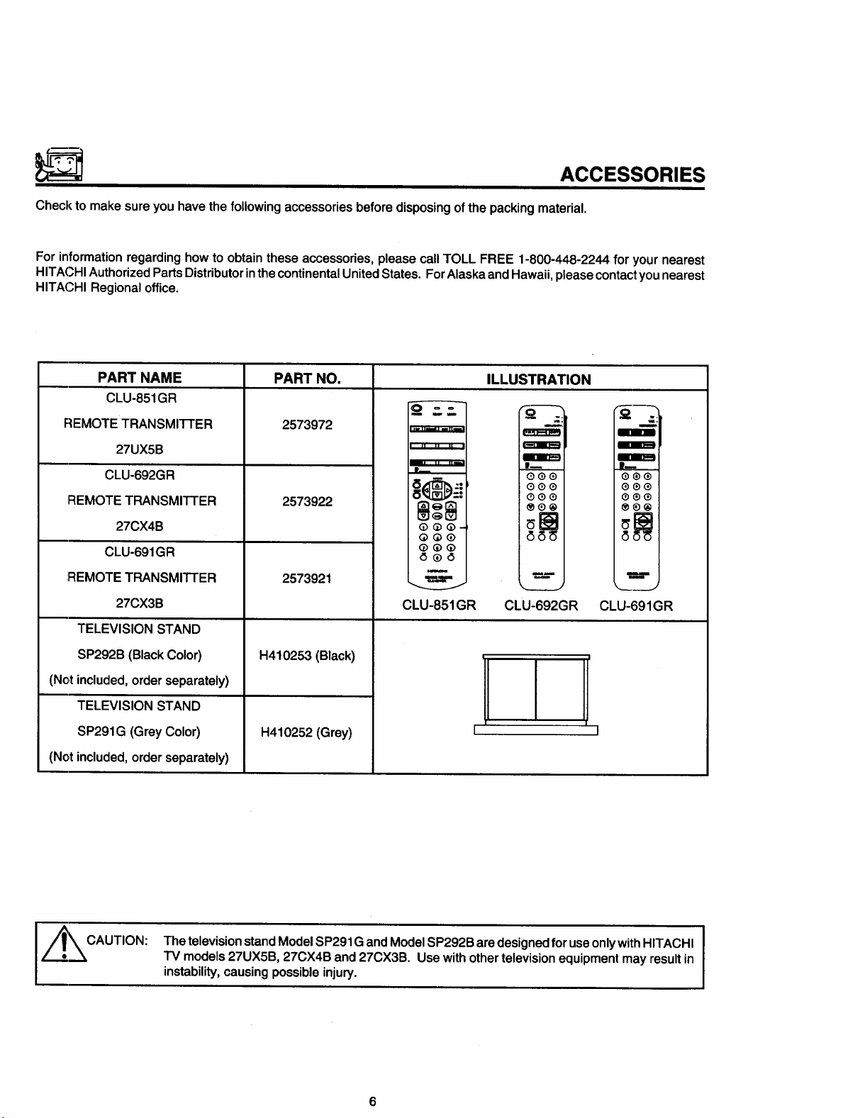
ACCESSORIES
Check to make sure you have the following accessories before disposing of the packing material.
For information regarding how to obtain these accessories, please call TOLL FREE 1-800-448-2244 for your nearest
HITACHI Authorized Parts Distributor in the continental United States. For Alaska and Hawaii, please contact you nearest
HITACHI Regional office.
PART NAME
CLU-851GR
REMOTE TRANSMI'N'ER
27UX5B
CLU-692GR
REMOTE TRANSMITTER
27CX4B
CLU-691GR
REMOTE TRANSMITTER
27CX3B
TELEVISION STAND
SP292B (Black Color)
(Not included, order separately)
TELEVISION STAND
SP291G (Grey Color)
(Not included, order separately)
PART NO.
2573972
2573922
2573921
H410253 (Black)
H410252(Grey)
ILLUSTRATION
!
' " " " II
Q@Q_
QQ@
®Q®
iooo
®o_
=rn'am
==lm==l
0®0
00@
00o
®0®
QQQ
m
____J
CLU-851GR CLU-692GR CLU-691GR
[- -]
CAUTION:
Thetelevision standModel SP291G andModelSP292B aredesigned for useonlywithHITACHI
TV models27UX5B,27CX4B and27CX3B. Use withothertelevisionequipmentmayresultin
instability,causingpossibleinjury.
6
Page 7
REMOTE CONTROL BATTERY INSTALLATION AND
REPLACEMENT
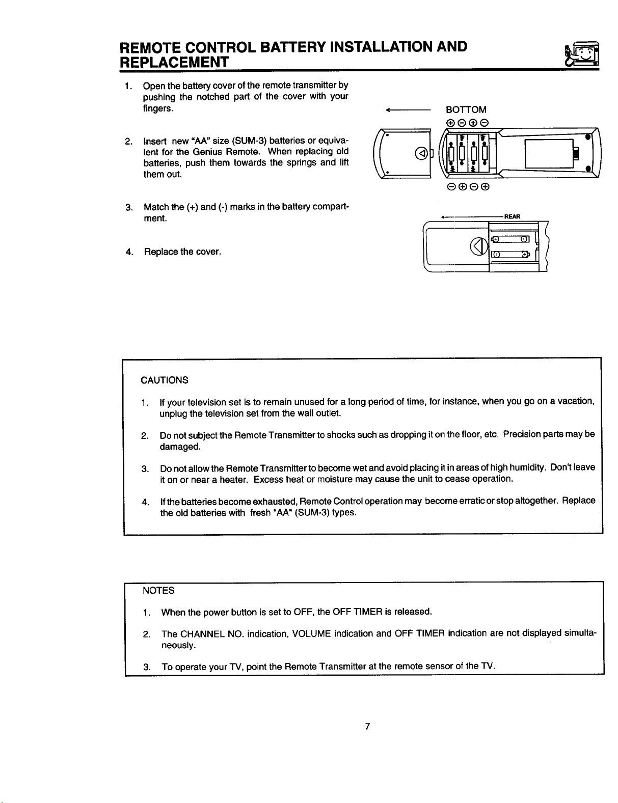
1.
Open the battery cover ofthe remote transmitter by
pushing the notched part of the cover with your
fingers.
2,
Insert new "AA" size (SUM-3) batteries or equiva-
lent for the Genius Remote. When replacing old
batteries, push them towards the springs and lift
them out.
.
Match the (+) and (-) marks in the battery compart-
ment.
4. Replace the cover.
BOTTOM
CAUTIONS
1.
If your television set is to remain unused for a long period of time, for instance, when you go on a vacation,
unplug the television set from the wall outlet.
2.
Do not subject the Remote Transmitter to shocks such as dropping it onthe floor, etc. Precision parts may be
damaged.
3. Do not allow the Remote Transmitter to become wet and avoid placing itin areas of high humidity. Don't leave
it on or near a heater. Excess heat or moisture may cause the unit to cease operation.
4. Ifthe batteries become exhausted, Remote Control operation may become erratic or stop altogether. Replace
the old batteries with fresh "AA" (SUM-3) types.
NOTES
1. When the power button is set to OFF, the OFF TIMER is released.
2. The CHANNEL NO. indication, VOLUME indication and OFF TIMER indication are not displayed simulta-
neously.
3. To operate your TV, point the Remote Transmitter at the remote sensor of the TV.
7
Page 8
HOW TO SET UP YOUR NEW HITACHI COLOR TV
ANTENNA
Unless your _ isconnected to a cable _ system or to a centralized antenna system, a good outdoor color _ antenna
is recommended for the best performance. However, if you are located in an exceptionally good signal area that is free
from interference and multiple image ghosts, an indoor antenna may be sufficient.
LOCATION
Select an area wheresunlightorbright indoorillumination willnotfall directly on the picture screen. Also, be surethat
the location selectedallowsa free flow ofairto and from thecoverof theset.
To avoidcabinetwarping, cabinetcolorchanges,and increasedchance of set failure, do not place the TV where
temperaturescanbecomeexcessivelyhot. Forexample,in direct sunlightor near a heatingappliance,etc.
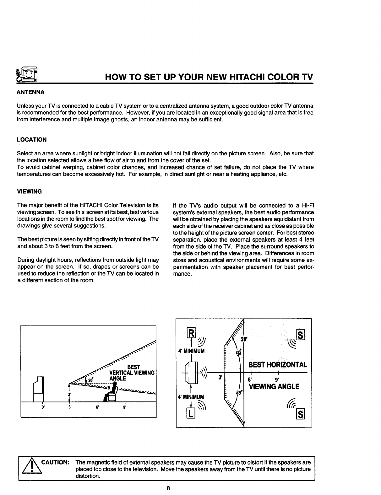
VIEWING
The major benefit of the HITACHI Color Television is its
viewing screen. To see this screen at its best, test various
locations in the room to find the best spot for viewing. The
drawiings give several suggestions.
The l-)estpicture is seen by sittingdirectly infront of the
and about 3 to 6 feet from the screen.
Dudng daylighthours, reflectionsfrom outsidelight may
appear on the screen. Ifso, drapesor screenscan be
usedto reducethe reflectionor the TV can be locatedin
a differentsectionofthe room.
If the TV's audio output will be connected to a Hi-Fi
system'sexternalspeakers,the bestaudioperformance
willbe obtainedbyplacingthespeakersequidistantfrom
eachsideofthereceivercabinetandascloseaspossible
tothe heightofthe picturescreencenter. Forbeststereo
separation,place the external speakersat least4 feet
from thesideof theTV. Place thesurroundspeakersto
thesideor behindtheviewingarea. Differencesinroom
sizesand acousticalenvironmentswillrequiresome ex-
perimentationwithspeaker placement for best perfor-
mance.
CAUTION:
The magneticfieldof external speakersmaycausethe _ picture to distort ifthe speakersare
placed too close tothe television. Move thespeakers away from the_ untilthere is no picture
distortion.
I
]
Page 9
HOOK-UP CABLES AND CONNECTORS
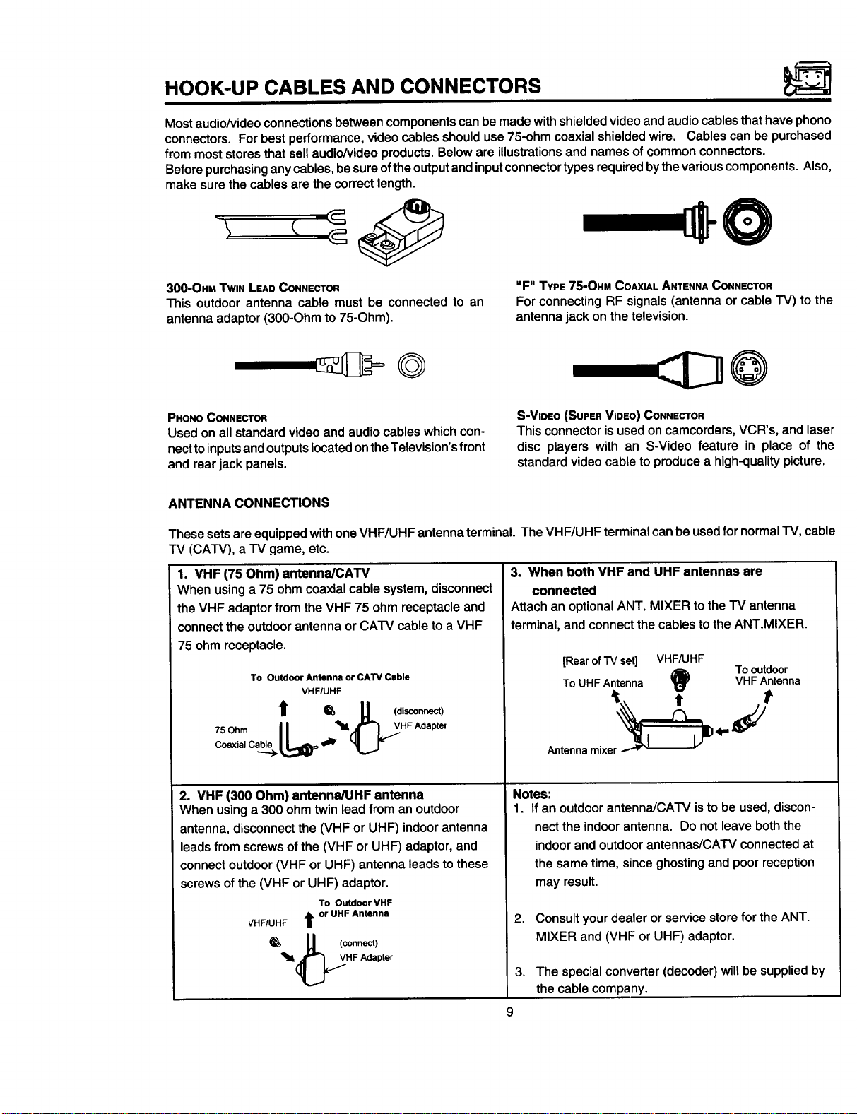
Most audio/video connections between components can be made with shielded video and audio cables that have phono
connectors. For best performance, video cables should use 75-ohm coaxial shielded wire. Cables can be purchased
from most stores that sell audio/video products. Below are illustrations and names of common connectors.
Before purchasing any cables, be sure of the output and input connector types required by the various components. Also,
make sure the cables are the correct length.
300-OHM TWIN LEAD CONNECTOR
This outdoor antenna cable must be connected to an
antenna adaptor (300-Ohm to 75-Ohm).
"F" TYPE 75-OHM COAXIAL ANTENNA CONNECTOR
For connecting RF signals (antenna or cable I-V) to the
antenna jack on the television.
©
PHONO CONNECTOR
Used on all standard video and audio cables which con-
nectto inputs and outputs located on the Television's front
and rear jack panels.
ANTENNA CONNECTIONS
These sets are equipped with one VHF/UHF antenna terminal. The VHF/UHF terminal can be used for normal TV, cable
TV (CATV), a TV game, etc.
1. VHF (75 Ohm) antenna/CAW
When using a 75 ohm coaxial cable system, disconnect
the VHF adaptor from the VHF 75 ohm receptacle and
connect the outdoor antenna or CATV cable to a VHF
75 ohm receptacle.
To Outdoor Antenna or CATV Cable
VHFIUHF
t = g (disconnect)
,SOhmII '"¢"I,V"FAdaP'e'
Coaxial C_I.I_ _ _
S-VIDEO (SUPER VIDEO) CONNECTOR
This connector is used on camcorders, VCR's, and laser
disc players with an S-Video feature in place of the
standard video cable to produce a high-quality picture.
3. When both VHF and UHF antennas are
connected
AttachanoptionalANT. MIXER tothe TV antenna
terminal,and connectthecablesto the ANT.MIXER.
[Rearof TVset] VHF/UHF
ToUHF Antenna VHF Antenna
Antenna mixer _ - -
Tooutdoor
4,"
2. VHF (300 Ohm) antenna/UHF antenna
When using a 300 ohm twin lead from an outdoor
antenna, disconnect the (VHF or UHF) indoor antenna
leads from screws of the (VHF or UHF) adaptor, and
connect outdoor (VHF or UHF) antenna leads to these
screws of the (VHF or UHF) adaptor.
To Outdoor VHF
VHF/UHF t or UHF Antenna
_, " (connect)
_ll_H F Adapter
Notes:
1. If an outdoor antenna/CATV isto be used, discon-
nect the indoor antenna. Do not leave both the
indoor and outdoor antennas/CArV connected at
the same time, since ghosting and poor reception
may result.
2.
Consult your dealer or service store for the ANT.
MIXER and (VHF or UHF) adaptor.
3,
The special converter (decoder) will be supplied by
the cable company.
9
Page 10
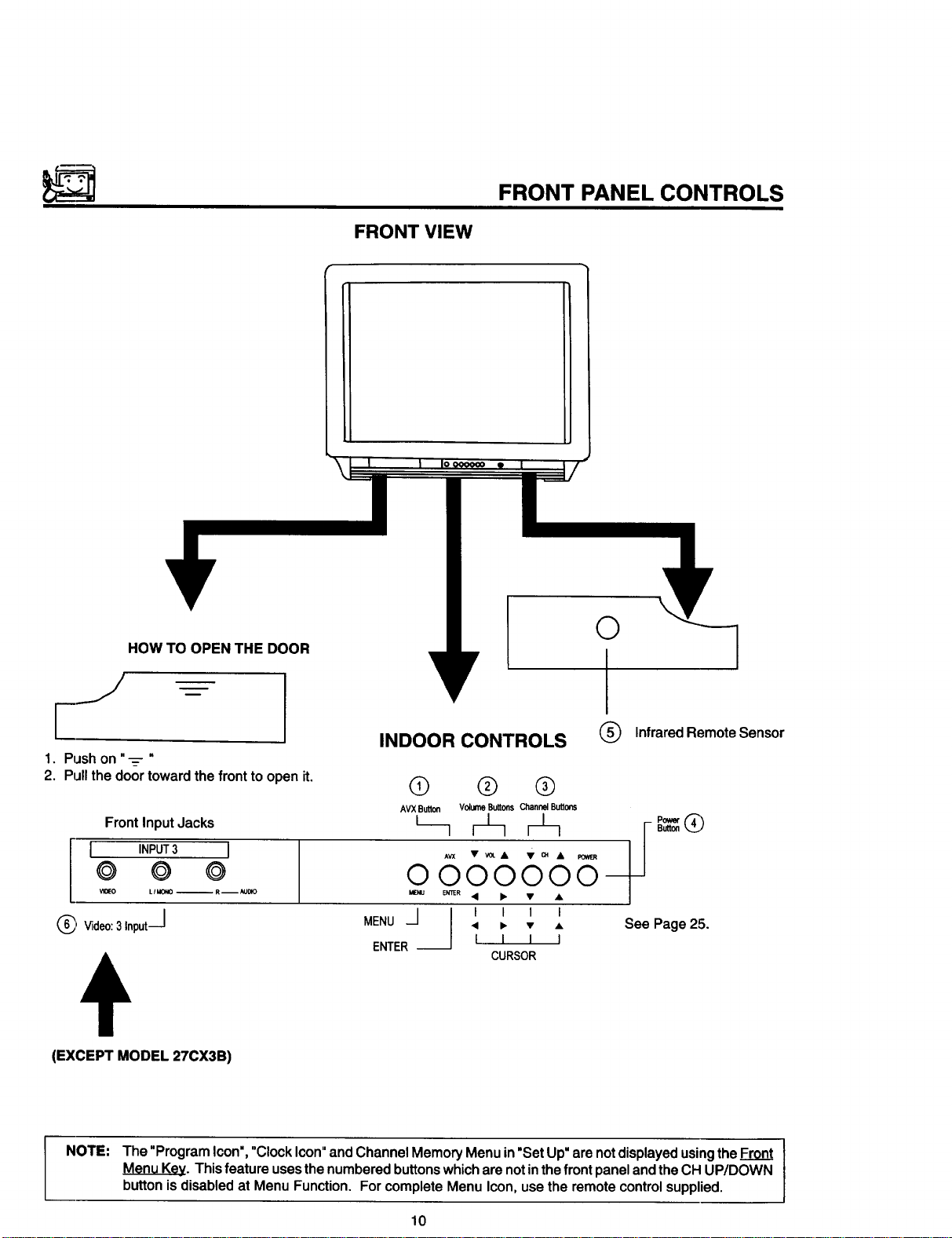
HOW TO OPEN THE DOOR
FRONT PANEL CONTROLS
FRONT VIEW
O
___//
INDOOR CONTROLS
1. Pushon "-=- "
2. Pullthedoortowardthefront toopenit.
FrontInputJacks
INPUT3 I
@ O ©
VIOEO L/MX_O -- R--AUOlO
/
(_ Video:3Input_J • • • •
(EXCEPT MODEL 27CX3B)
NOTE: The "ProgramIcon',"Clock Icon"andChannelMemoryMenuin"SetUp"are notdisplayedusingtheFront
MenuKey. Thisfeature usesthenumberedbuttonswhicharenotinthefront panelandtheCH UP/DOWN
buttonisdisabledat MenuFunction. ForcompleteMenuIcon,use theremotecontrolsupplied.
O ® ®
AVXButton Volume Buttons ChannelButtons
0000 0
_NU e,rnER• •
MENU --]
ENTER --
I I I I
I I I I
CURSOR
Q InfraredRemoteSensor
P_Q
Button
See Page25.
10
Page 11
FRONT PANEL CONTROLS
0 AVX(Audi_ldeo) selector
Press this button to select the current antenna source, or VIDEO: 1,2 or 3. Your selection is shown in the top right
comer of the screen. Model 27CX3B does not have VIDEO: 3.
Q VOLUME level
Pressthese buttons for yourdesired soundlevel. The volume level willbe displayed on the "IVscreen.
(_ CHANNEL selector
Pressthese buttonsuntilthedesiredchannelappearsin thetop rightcornerof theTV screen.
(_) POWER button
Pressthisbutton to turnthe "IVON orOFF.
NOTE: YourHITACHITV willappeartobeturned=OFP IfthereisnovideoinputwhenVIDEO: 1,2, or3 isselected.
PressAVX untilit returnstothe same VIDEO: 1,2or 3, ifnot Power is"OFF'.
(_) REMOTE CONTROL sensor
PointyourGeniusRemoteat thisarea when selectingchannels,adjustingvolume,etc.
(_ FRONT INPUT JACKS (for VIDEO: 3)
Use these audio/video jacks for a =quick" hook-up from a camcorder or VCR to instantlyview your favorite show or
new recording. (Press the AVX button until VIDEO: 3 appears in the top right corner of the IV screen.)
11
Page 12
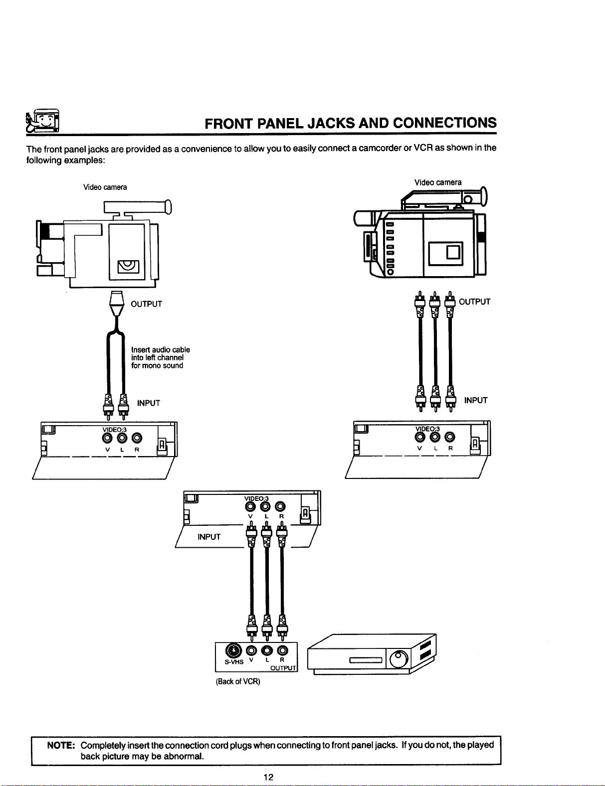
FRONT PANEL JACKS AND CONNECTIONS
The front panel jacks are provided as a convenience to allow you to easily connect a camcorder or VCR as shown in the
following examples:
Video camera
OUTPUT
Insertaudio cable
intoleftchannel
for mono sound
INPUT
Videocamera
OUTPUT
INPUT
NPUT
V L R
S-VHS _ ii_
r-------1
(BackofVCR)
NOTE: Completely insertthe connection cord plugswhen connecting to frontpanel jacks. Ifyou do not,the played
back picture may be abnormal.
12
Page 13
REAR PANEL
JACKS
-- AUDIO to HI-FI OUTPUT
,=&o
IO_R __.__
TERMINALS
INPUT TERMINALS _)
I
_IDEO _nDEO
®
-@
O
S-VIDEC
@
AUtO AUtO
VHF/UHF
Q VHF/UHF ANTENNA TERMINAL
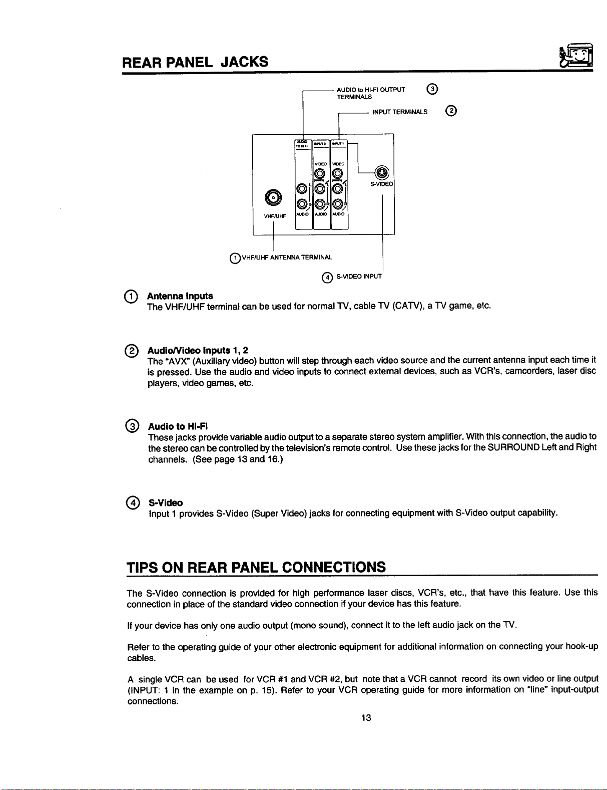
Antenna Inputs
©
The VHF/UHF terminalcanbe usedfor normalTV, cableTV (CATV), a IV game,etc.
Audio/Video Inputs 1, 2
®
The =AVX"(Auxiliaryvideo)buttonwillstep througheachvideosourceandthe currentantennainputeachtimeit
is pressed.Use the audioand video inputsto connectexternaldevices, suchas VCR's, camcorders,laserdisc
players,videogames, etc.
uJoto
I
_) S-VIDEO INPUT
Audio to HI-Fi
@
Thesejacksprovidevariableaudiooutputtoa separatestereosystemamplifier.Withthisconnection,theaudioto
thestereocanbecontrolledbythe television'sremotecontrol.Usethesejacksfor theSURROUND LeftandRight
channels. (See page 13 and 16.)
Q S-Video
InputI providesS-Video(Super Video)jacksfor connectingequipment withS-Videooutputcapability.
TIPS ON REAR PANEL CONNECTIONS
The S-Video connectionis providedfor high performancelaser discs,VCR's, etc., that have thisfeature. Use this
connectionin placeofthe standardvideoconnectionifyourdevicehasthisfeature.
Ifyour devicehas onlyoneaudiooutput(monosound),connectittothe leftaudiojack onthe IV.
Refer tothe operatingguideofyour otherelectronicequipmentforadditionalinformationonconnectingyourhook-up
cables.
A singleVCR can be used for VCR #1 and VCR #2, but notethata VCR cannot record itsownvideoor lineoutput
(INPUT: 1 in the example on p. 15). Refer to yourVCR operatingguidefor more informationon "line"input-output
connections.
13
Page 14
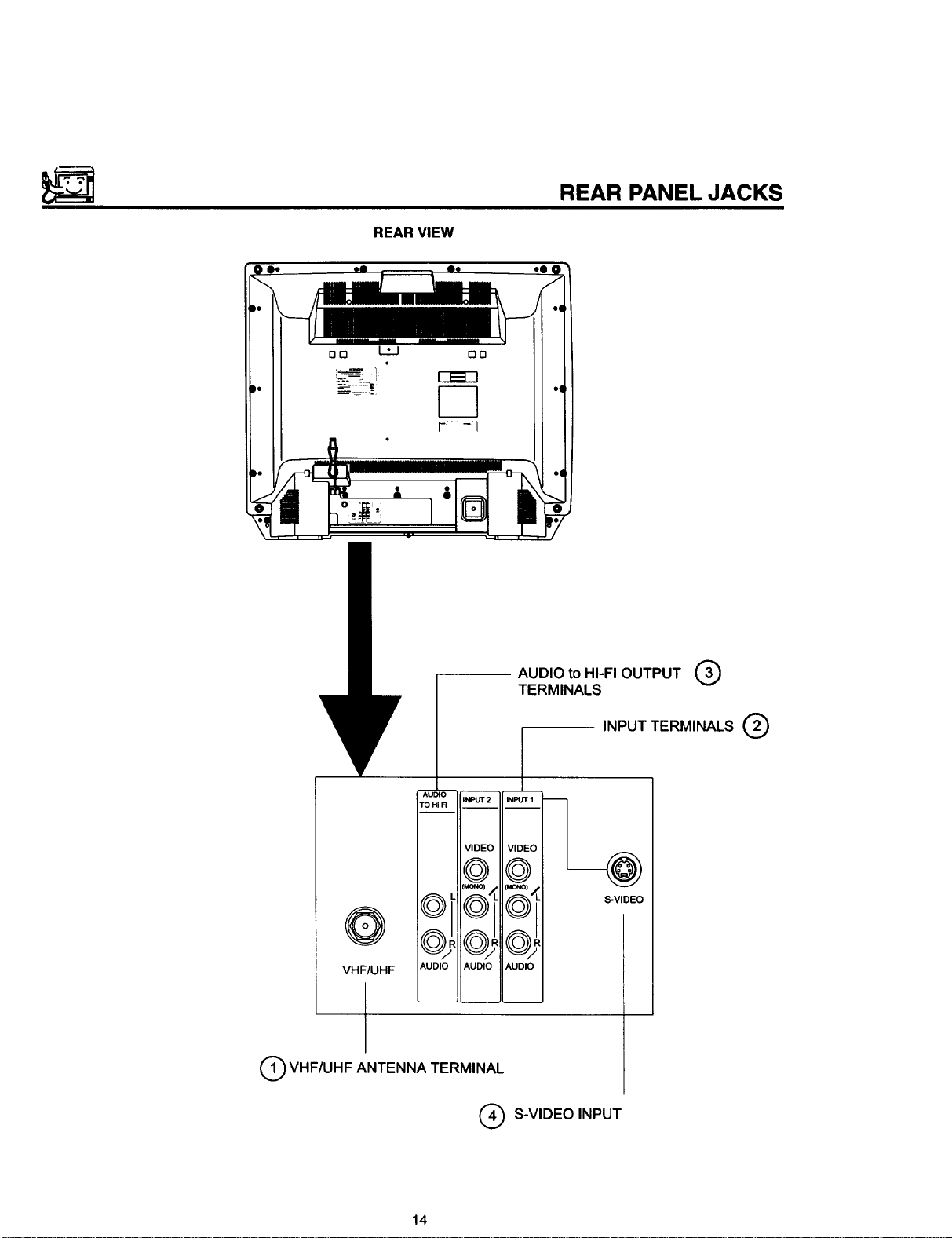
REAR VIEW
REAR PANEL JACKS
m m
AIJ
IO
TO I
R _NPUT 2
VIDEO
©
MONO) •
O
AUI
VHF/UHF
Q VHF/UHF ANTENNA TERMINAL
IO AUDIO
Q S-VIDEO INPUT
AUDIO to HI-FI OUTPUT (,3)
TERMINALS
INPUT TERMINALS Q
_m
t_lPt T 1
VIE EO
C_t
AU[ IO
S-VIDEO
14
Page 15
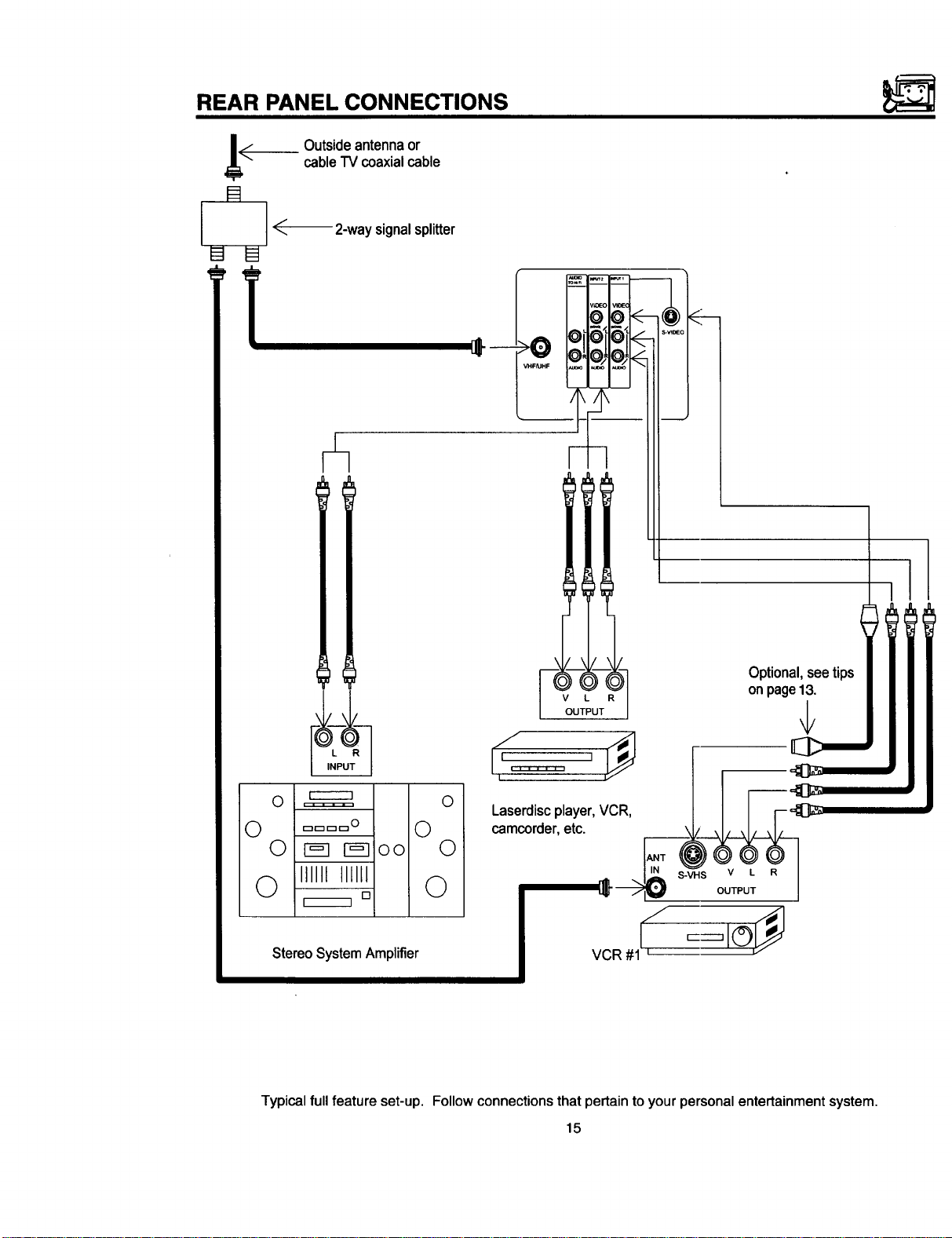
REAR PANEL CONNECTIONS
Jii<_ Outside antennaor
cableTV coaxialcable
R
I
[]
I_-_ 2-waysignalsplitter
VHFAJHF
Optional, see tips
on page13,
r------q
O ===== O
0 =D==o 0
Laserdisc player, VCR, I r---_
camcorder, etc. \/ ,I,,F"
0 _ r-=-l!oo 0
0 IIIIII IIIIII 0
Stereo System Amplifier
Typical full feature set-up. Follow connections that pertain to your personal entertainment system.
[]
15
Page 16
EXTERNAL CONNECTIONS
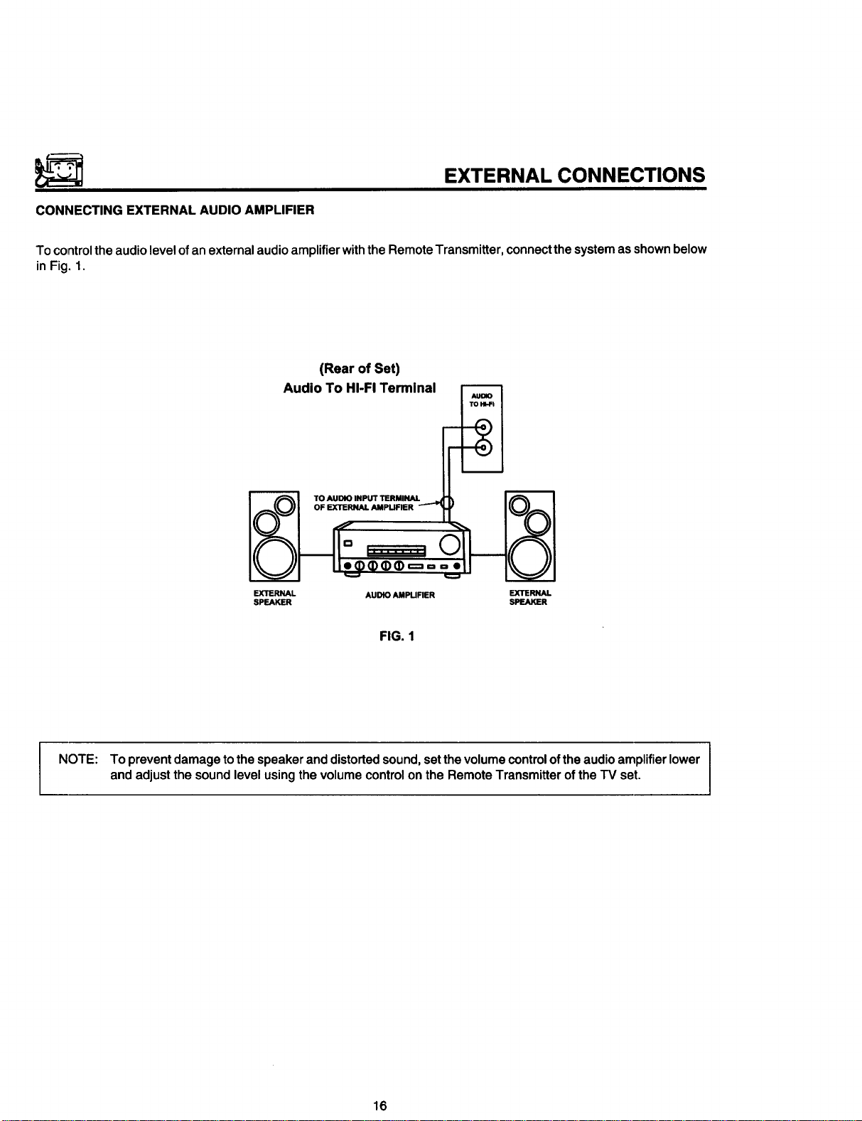
CONNECTING EXTERNAL AUDIO AMPLIFIER
To control the audio level of an external audio amplifier with the Remote Transmitter, connect the system as shown below
in Fig. 1.
(Rear of Set)
Audio To HI-FI Terminal
TO AUDIO INPUT TERMINAL
OF EXTERNAL AMPUFIER
EXTERNAL AUDtO AMPUFIER EXTERNAL
SPEAKER SPEAKER
FIG. 1
NOTE: To prevent damage tothe speakeranddistorted sound,setthevolumecontrolofthe audioamplifierlower
andadjustthe soundlevelusingthevolumecontrolonthe RemoteTransmitteroftheTV set.
16
Page 17
CONNECTING EXTERNAL VIDEO SOURCES
The exactarrangementyou usetoconnecttheVideoCassetteRecorder,VideoDiscPlayerandVideoCamera toyour
TV setis dependentonthe modelandfeatures ofeach component.ChecktheOwner'sManualofeachcomponentfor
thelocationofits videoand audioinputsandoutputs. The following connectiondiagramsare offeredas suggestions.
However,youmay needto modifythemto accommodateyourparticularassortmentofcomponentsand features. For
bestperformance, videoand audiocablesshouldbe madefrom coaxialshieldedwire.
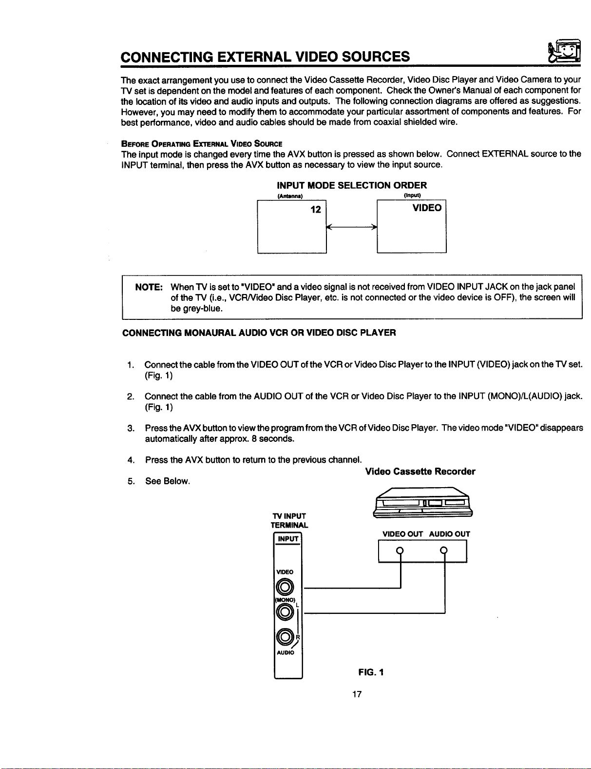
BEFORE OPERATING EXTERNAL VIDEO SOURCE
The inputmodeischangedeverytime theAVX button ispressed as shownbelow. Connect EXTERNAL sourceto the
INPUT terminal,thenpressthe AVX buttonas necessarytoviewthe inputsource.
INPUT MODE SELECTION ORDER
(Antenna) (Input)
121 _I VIDEO
NOTE: WhenTV issetto "VIDEO"anda videosignalisnotreceivedfromVIDEO INPUTJACKonthejackpanel
ofthe "IV (i.e., VCRNideo DiscPlayer,etc.is notconnectedor thevideodeviceisOFF), thescreenwill
be grey-blue.
CONNECTING MONAURAL AUDIO VCR OR VIDEO DISC PLAYER
1.
Connect thecable from the VIDEO OUT ofthe VCR orVideoDisc Playertothe INPUT (VIDEO)jack ontheTV set.
(Fig. 1)
2.
Connect the cable from the AUDIO OUT of the VCR or Video Disc Player to the INPUT (MONO)/L(AUDIO) jack.
(Fig. 1)
.
PresstheAVXbuttontoviewtheprogramfromtheVCR ofVideoDiscPlayer. Thevideomode"VIDEO" disappears
automaticallyafterapprox.8 seconds.
4. Pressthe AVX buttonto returntothe previouschannel.
Video Cassette Recorder
5. See Below.
TV INPUT
TERMINAL
i
_DEO
VIDEO OUT AUDIO OUT
¢_-_ _,
_JI
AUDIO
FIG. 1
17
Page 18
CONNECTING EXTERNAL VIDEO SOURCES
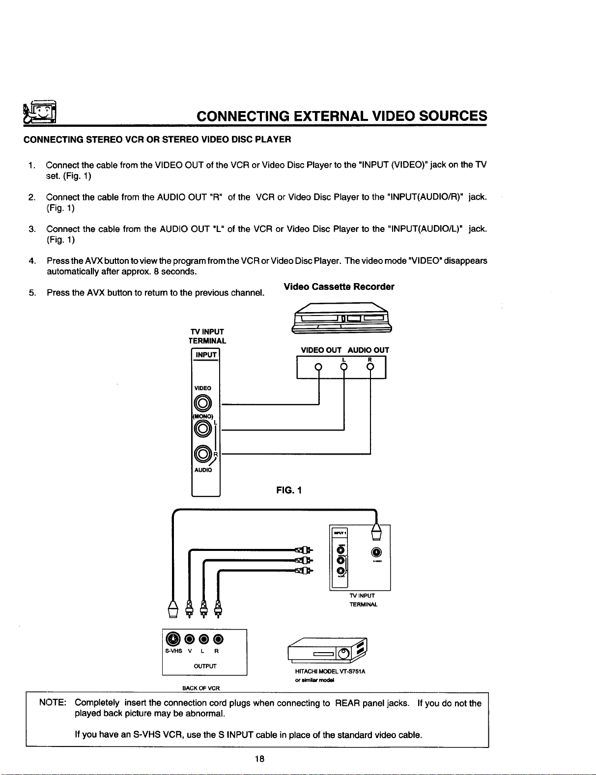
CONNECTING STEREO VCR OR STEREO VIDEO DISC PLAYER
1,
Connect the cable from the VIDEO OUT of the VCR or Video Disc Player to the "INPUT (VIDEO)" jack on the TV
set. (Fig. 1)
2.
Connect the cable from the AUDIO OUT "R" ofthe VCR or Video Disc Player tothe "INPUT(AUDIO/R)" jack.
(Fig. 1)
3,
,Connect the cable from the AUDIO OUT "L" of the VCR or Video Disc Player to the "INPUT(AUDIO/L)" jack.
(Fig. 1)
4.
Press the AVX button to view the program from the VCR or Video Disc Player. The video mode "VIDEO" disappears
automatically after approx. 8 seconds.
5. Press the AVX button to return to the previous channel.
Video Cassette Recorder
TV INPUT
TERMINAL
INPUT
VIDEO
MONOI
AUDIO
d
,., ,,
VIDEOOUT AUDIOOUT
L R
FIG. 1
TV INPUT
TERMINAL
NOTE:
HITACHI MODEL V'F-S751A
or _nilar model
BACK OF VCR
Completely insert the connection cord plugs when connecting to REAR panel jacks.
played back picture may be abnormal.
Ifyou have an S-VHS VCR, use the S INPUT cable in placeof thestandardvideocable.
18
If you do not the
Page 19

AUDIO SYSTEM SET-UP
Match the numbers below to the diagram for speaker placement and refer to the table for the different surround sound
requirements. (See page 53 for SURROUND functions.)
O The television's internal speakers.
O These speakers are connected to a separate audio amplifier. Use the "Audio to Hi-Fi" output on the IV.
1[
I
SURROUND REQUIRED OPTIONAL EFFECT
FEATURE CONNECTION CONNECTION
OFF O Q Receive Mono and Stereo Sound.
SIMULATE Q Q
MUSIC
MOVIE
®®
©®
19
At Mono Input, sound is changed more loudly
At stereo Input, sound of music is changed more
loudly, Surround Channel added to left and right
Audio Amplifier speakers.
Movie Theater Reproduction, Surround Channel
added to left and right audio amplifier speakers.
Page 20

THE GENIUS REMOTE CONTROL (CLU-851GR)
(MODEL 27UX5B)
Inadditiontocontrolling allthefunctions onyour HITACHI
Color-I'V,thenewGenius Remoteisdesignedtooperate
differenttypes of VCR's and differenttypes of CATV
(Cable,TV) converterswith one touch. Basic operation
keysaregroupedtogetherinonearea. Allothercontrols
are separatedfrom themand arrangedin MULTI-PAGE
To operate your TV, point the Genius Remote at the remote sensor of the TV.
To operate your VCR, point the remote at the remote sensor of the VCR.
@
@
©
POWER
READY LEARN
sections,witha displaythatcan beswitchedto coverany
of the four pages. Functionsare arrangedand properly
categorizedintowindows,makingoperationsimplewhen
multiplefunctions are tobe controlled.
READY indicator light
Refer to Page 34.
SEND/LEARN indicator light
Refer to page 34.
....................:-;-}E:::::::::::::::::::::::::
LEARN/USE select switch
(Locatedonrear sideof remotecontrol)
_-_-_-r-7 !
.........IIIIP_;_;_:................................
CURSOR
USE_
C_NEL
@@
Q@
@iL_,
®j
®
@@
A_
o®
H rrACHI
GENIUS REMOTE
CLU-851GR
.@..]
11117
0
LEARN........ Entersthe Learningmode.
USE............ Setfor normaluse.
MULTI-PAGE
This selects the button layout of the multi-page
section of the remote control.
(_) MULTI-PAGE buttons
These buttons change functions as shown on
page 21.
,Q LIGHT button
Whenyou are in a dark room, pressthisbutton on
thesideoftheremoteto lightupthebuttonsshown
in(_. The lightwillstayonfor about8 secondsif
nobuttonispressed.The buttonswillnotappearto
lightifthe roomis toobright.
20
(Refer topage 34.)
select switch
Page 21

MULTI-PAGE WINDOWS
POWER READY LEARN
(_ _ CD
POWER READY LEARN
plEPI kXCHNdI SHIFTIIFREEZd1
!l II II II Ii
I]ILo,,=
MENU
POWER READY LEARN
CURSOR
_:_0
o_ 0
u_O
When "IV" is set
lr_r_7_rr--q
_SELECT
SWITCH
!,-v_ o!
! 00 SELECT!
CURSOR
vc.@
caw 0
usr=.0
When "VCR" is set
POWER READY LEARN
II ,', II B II c II D I
SELECT
SWITCH
li ti tl II li
!1 II II I ISELECTII
IIILo._
MENU
When "CAIV" is set When "USER" is set
CURSOR
_:_0
_ •
U_R 0
_SELECT
SWITCH
21
II E II F I1 G II H I!
I]IL,...E
MENU
CURSOR
TvO
_0
cAT_0
_SELECT
SWITCH
Page 22

THE GENIUS REMOTE CONTROL (CLU-692GR)
with P-in-P (MODEL 27CX4B)
Inaddition to controlling all the functions on your HITACHI
Color TV, the Genius Remote Control is designed to
operate different types of VCR's (Also Abbreviated VTR)
and different types of CATV converters (cable boxes) with
one touch. Basic operating buttons are grouped together
in one area. All other controls are separated from them
N()TE: Precoded buttons (@ below) will control HITACHI TV only when the MULTI-PAGE SELECT SWITCH i
(@ below) is set to "TV" mode.
To operate your TV, point the Genius Remote at the remote sensor of the TV.
To operate you VCR, point the remote at the remote sensor of the VCR.
To operate your cable box, point the remote at the remote sensor of the cable box.
POWER "rv
[<1411 • I IIH_I)
o
VTR
MENUiCAI_
" ............ I
((• ii mii. )1
and arranged in MULTI-PAGE sections, with a display
that can be switched to cover any of the three pages.
Functions are arranged and properly categorized into
windows. Making operation simple even when multiple
functions are to be controlled.
MULTI-PAGE SELECT SWITCH
®
Slide the switch in the direction of the arrow to select
the MULTI-PAGE mode.
Button layout when "TV" is selected.
®
The P-IN-P, SHIFT, EXCHNG and FREEZE buttons.
Button layout for "VCR."
®
(Power button turns the VCR ON or OFF.)
I
GENIUS REMOTE
HITACHI
CLU-692GR
...........
: VTR
•....M.EN.U._
®
I
Button layout for "MENU/CATV."
®
(Power button turns cable box ON or OFF.)
See pages 31, 32, 33.
TV EXCLUSIVE BUI-I-ONS
®
These will always control the TV even when the
Multi-Page select switch is in the VCR or MENU/
CATV position.
PRECODED BUTTONS
®
These buttons will control a VCR or a cable box
when the Multi-Page select switch is in the VCR or
MENU/CAIV position.
®
LIGHT BUTTON
...........
®
Whenyouare ina darkroom,pressthisbuttononto
lightuptheChannelKeys,Volume,and theUpand
Down Keys. The lightwill stay ON for about 8
secondsifno buttonispressed.Thebuttonswillnot
appearto lightifthe roomis toobright.
22
Page 23

THE GENIUS REMOTE CONTROL (CLU-691GR)
without P-in-P (MODEL 27CX3B)
Inadditionto controllingallthefunctions onyour HITACHI
Color TV, the Genius Remote Control is designed to
operatedifferenttypesofVCR's (AlsoAbbreviatedVTR)
and differenttypes ofCATVconverters(cableboxes)with
onetouch. Basicoperatingbuttonsare groupedtogether
in one area. All othercontrolsare separatedfrom them
To operate your TV, point the Genius Remote at the remote sensor of the TV.
" To operate you VCR, point the remote at the remote sensor of the VCR.
To operate your cable box, point the remote at the remote sensor of the cable box.
t'--_ TV
.......... VTR
MENU_-.w_TV
POWER TV
V'TR
MEN_TV
('_11 • I1_))
T
( • II • II II ))
and arranged in MULTI-PAGE sections, with a display
that can be switched to cover any of the three pages.
Functions are arranged and properly categorized into
windows. Making operation simple even when multiple
functions are to be controlled.
MULTI-PAGE SELECT SWITCH
®
Slide the switchin the direction of the arrow to select
the MULTI-PAGE mode.
Button layout when "TV" is selected.
®
Buttonlayout for "VCR."
®
(Powerbuttonturnsthe VCR ON orOFF.)
GENIUS REMOTE
HITACHI 1
CLU-691GR
Button layout for "MENU/CATV."
®
(Power button turns cable box ON or OFF.)
See pages 31, 32, 33.
"IV EXCLUSIVE BUTTONS
®
These will always control the IV even when the
Multi-Page select switch is in the VCR or MENU/
®
POWER: w
: wm
',...._u_E
((MENUlI • I ]_NT_)
CArV position.
PRECODED BUI-FONS
These buttons will control a VCR or a cable box
when the Multi-Page select switch is in the VCR or
MENU/CATV position.
i
®
23
LIGHT BUTTON
When you are in a dark room, press this button on to
light up the Channel Keys, Volume, and theUp and
Down Keys. The light will stay ON for about 8
seconds if no button is pressed. The buttons will not
appear to light if the room is too bright.
Page 24

HOW TO USE THE GENIUS REMOTE TO CONTROL YOUR TV
Detailed explanation of the circled numbers is on the following pages.
-._ _ _:_
POWER READY LEARN
,I PINPI l_c;'ll_(_iI SHIFTI IFREEZ4
...................................
! It II II II
@
I II II IIREC_LLI
III!....
............._ ......
HITACHI
GENIUS REMOTE
CLU_51GR
rC;_ ",
POWER T_/ •
PINP| _ IS_.='r
I
mp .uLn_
VIA.
MENU/CATV.
O
O
POWER _ •
II
mp auLn_
VTR•
MENUiCATV.
®
®
0001
ooei
000
®0®
GENIUS REMOTE
HITA£_HI
\
?
®
CLU-692GR
?
®
HITACHI [
POWER T_ q
MENU/CArVe
[UENUlI & I ll_
_4_1 LL I_i
24
VTR.
.._@
POWER "rv .
tlua_uli & I lemlallI
v'rR.
MENUiCATV=
--@
Page 25

HOW TO USE THE GENIUS REMOTE TO CONTROL YOUR TV
@ POWER button
PressthisbuttontoturntheTV set ON orOFF. If
an automaticmessageis set,it willbe displayed
whenthe"IV isfirst turnedON. (See page49.)
RECALL button
®
When you want to check the channel being re-
ceived, or if it has a stereo (ST) or second audio
program (SAP), press the RECALL button.
You can alsocheckthetime, and iftheON TIME
or OFF TIME has been set. (See page 48.)
Channel and
CHpATNINoEL- Audio _elected / Antenna Source
1 '.EWS STE_E0 _1"[L
l ST/SA,_. Audio broadcast
AUTOMAT,C__J. , II
MESS G -oooo II
........ "_1 P ON 7"00 AM I I
UI-I- /Iil'-I_ ._OFF 9;00 PM 10:15 ,_ TIME
ONTIMER" I =...... = III
If a video input is used:
Video Input
/
J
VIDEO:I
.s Whenan S-Video
(S-IN)
inputis connected
(3)--
@
®
POWER READY LEARN
IPINPI IEXCHN4I SHIFTIIFREEZ_
I
RECAL I
NIP ...... _E
[;;_,_u........._ .......i
@@@i
AVX
o@6
HITACHI
GENIUS REMOTE
CLU-851GR
/
-@
You can also use the RECALL button to quickly clear
many of the other On-Screen displays.
25
Page 26

HOW TO USE THE GENIUS REMOTE TO CONTROL YOUR TV
MENU, ENTER, and CURSOR buttons
®
All the On-Screen display features can be set or adjusted by using these buttons.
The "MENU" button will start or exit the On-Screen display.
The "CURSOR" buttons will highlightfunctions or adjust different features.
These buttons are also used for FAVORITE CHANNELS. (See page 43 .)
The =ENTER" button will set features to your preference.
"CHANNEL SELECT" buttons are used to set the time, channel memory, etc.
CHANNEL SELECTOR buttons
®
I-ntertwoorthreenumberstoselectchannels.Entera"0"firstforchannels1to9. Usethe"100" buttonforchannels
100 and higher.
Channel selection may also be performed by pressing channel up (•) or down (•).
NOTE: The TV may not receive some channels if you are not in the correct AIR/CABLE mode. See page 40. I
Q AVX button
TheAVX (AuxiliaryVideo) button willselect betweentheantennasignal and thethree setsofvideo inputjackseach
time thebuttonis pressed.
VIDEO:I
(S-IN)
AVX
==
AVX AVX
O O
I
VIDEO:3 VIDEO:2
AVX
O
(Except Model 27CX3B)
26
Page 27

HOW TO USE THE GENIUS REMOTE TO CONTROL YOUR TV
(_) VOLUME, MUTE buttons
Pressthe "VOLUME" up ( • ) ordown( • ) button untilyou obtainthe desired sound level.
To turnthe soundOFF instantly toanswer the telephone,etc.,pressthe"MUTE" button. Pressthe"MUTE" button
againor pressthe "VOLUME" up (• ) buttontorestorethesound.
MTV STEREO 28
Louder
IIHIIIIIUlIUlIIIIIIIIII'"'""""'""""""'
VOLUME
v
The word "MUTE" will remain displayed if the CLOSED CAPTION feature is turned OFF.
>
The word "MUTE" will not be displayed if the CLOSED CAPTION feature is ON.
@ LAST CHANNEL (LST-CH) button
Usethisbutton to select between the lasttwo channelsviewed.(Goodfor watchingtwo sportingevents,etc.)
PRME STEREO 28
ST/SA
STEREO
Q PICTURE-IN-PICTURE buttons
See separate sectiononpage28 for a description.
LIGHT Bu'n'ON
When you are in a dark room, press this button to light up the volume and channel buttons, The light will stay ON
for about 8 seconds if no buttons is pressed. The buttons will not appear to light if the room is too bright.
27
Page 28

PICTURE-IN-PICTURE (P-IN-P) MODELS 27UX5BI27CX4B
The Picture-in-Picture feature isconvenient when you want to watch more than one program at the same time.
You can watch a TV program while viewing a VCR program (TV or tape) onvideo input 1, and vice versa withthis feature.
Front or back of TV
OO©
kV. l
VIDEO IN
f_
POWER R_Y L_N
l
I "'1"' I 1_"'_4 I _"II''-E_I
POWER TV,
I ME N LI;CATV •
(_N PI Ir_ ISHIFT) I
VTRe
' I I
I II II II I
[_-_
I II I ! I I ,_,-'-I
r--------n
CLU-851GR
P-IN-P BUTTON
Press the "P IN P" button and a sub-picture appears in one corner of the screen. Press the button a second time
to remove the sub-picture fromthe screen. TheIV channel willalways be either the main picture or the sub-picture.
Main Picture
NEWS STEREO
CLU-692GR
Sub-Picture
@ EXCHNG (EXCHANGE) BUTTON
If you wish to switch what is being shown on the main picture to the sub-picture, press the "EXCHNG" button.
I NEWS STEREO 31 !
ST/SA
28
Page 29

PICTURE-IN-PICTURE (P-IN-P)
Q SHIFT BU'rTON
To movethe sub-pictureto another corner, press the "SHIFT"button. The sub-picture movesone step counter-
clockwiseeverytimethe "SHIFT" buttonispressed.
FREEZE BUTTON
®
If you wishto freeze thesub-picture,press "FREEZE" button. This isconvenientwhentryingto writedown the
addressforamailordercompany,recordingstatisticsfor a sportingevent,etc. Toreturntomotion,pressthebutton
again.
Q FREEZE BUTTON WITHOUTA SUB-PICTURE
Pressthisbuttonwithoutasub-picturetofreezethepictureyou are currentlyviewing. Pressthisbutttonagainor
P INPtoreturntonormalviewing.The EXCHNGpicture-in-picturefunction willnotworkwiththisFREEZEfunction.
/_kCAUTION: pattern burn may develop if the sub-picture is left in the same corner permanently. If the
NOTE:
1. Only sound from the main picture can be heard.
2. P-IN-P will not work with a CHILD LOCK channel as the Main Picture but it will be displayed as a Sub-Picture.
3. The Sub-Picture will not appear while a FAVORITE CHANNEL is being selected. The Sub-Picture will reappear
after the FAVORITE CHANNEL display is gone.
4. When the "P-in-P" button is pressed, the sub-picture will appear in the same position as previously set.
5. The "FREEZE" function is released when the"EXCHNG" button is pressed.
6. The P-in-P sub-picture only works on VIDEO:I input.
A
P-IN-P feature is used frequently, occasionally shift the sub-picture to a different corner.
29
Page 30

USING THE GENIUS REMOTE TO CONTROL VCR FUNCTIONS
OPERATING THE PRE-CODED FUNCTION FOR YOUR VCR.
This Genius Remote is designed to operate different types ofVCRs. You must first program the Genius Remote to match
the remote system in your VCR. (Refer to Table 1 on page 32 or Table 3 on page 33.)
1. Set the MULTI-PAGE select switch to "VCR."
2. Set the USE/LEARN mode select switch on the rear side of the Genius Remote to 'USE." (For CLU-851GR only)
3. Turn ON your VCR.
4. Aim the Genius Remote control at the front of your VCR.
5.
While holding down the SELECT button, press the button that matches your VCR as shown on page 32 or page 33.
Continue to hold down both buttons. The channels of the VCR will begin changing when the correct button is
pressed. When this occurs, the Genius Remote Control is programmed for your VCR. If the VCR channels do not
change after 5 seconds, try a different Genius Remote button.
6. Release both buttons when the VCR starts to change channels. The Genius Remote will now control your VCR.
NOTES:
1. Ifyour VCR cannot be operatedafterperforming
the above procedures,this means that your
VCR's codeshave notbeen precodedintothe
GENIUS REMOTE. Please store your VCR
codes in memory by using the USER mode.
(Refer topage 34.)
2. The GENIUS REMOTE CONTROL willremem-
berthecodesyouhave programmedinuntilthe
batteriesare removed from the GENIUS RE-
MOTE CONTROL. Afterreplacingthe batteries
repeattheentireprogrammingprocedurestated
above.
3. If you havea playbackonly VCR (no CH UP/
DOWNfunction), pleasefollow operatingstep5
describedaboveandthencheckaVCR function
untilyoufindthebuttonthatwillallowtheprecoded
VCR buttonstooperateyourVCR.
PRECODED VCR BUTTONS
(i)
These buttons always transmit the chosen precoded
VCR codes.
O
POWER
(:_ (_
READY LEARN
=.,..............................
11 l, o !
•............................ ,
CHANNEL
CURSOR
G
®
i
i
SELECT BUTTON
®
This is for setting upthe Genius Remote to transmit
the VCR's remote codes.
EXCLUSIVE "rvBUTTONS
@
These buttons are for operatingthe IV.
3O
@
HITACHI
GENIUSREMOTE
CLU-851GR
Page 31

USING THE GENIUS REMOTE TO CONTROL CABLE
BOX FUNCTIONS
OPERATING THE PRE-CODED FUNCTION FOR YOUR CABLE BOX.
This GeniusRemote isdesigned tooperatedifferent typesofcableboxes.You mustfirst programthe Genius Remote
to matchtheremotesysteminyour cablebox. (RefertoTable 2 on page32 orTable 4 on page 33.)
1. Set the MULTI-PAGE select switch to "CATW'
2. Set the USE/LEARN mode select switch to "USE." (For CLU-851GR only)
3. TurnON yourcablebox.
4. Aim the GeniusRemotecontrolatthe front ofyourcable box.
5.
Whileholding downthe SELECTbutton, pressthebutton thatmatchesourcablebox asshownonpage32 orpage
33. Continuetoholddownbothbuttons.Thechannelsofthecableboxwillbeginchangingwhenthecorrectbutton
ispressed. Whenthisoccurs,theGeniusRemoteControl isprogrammedfor yourcablebox. If thecablebox
channels do notchangeafter 5 seconds,trya different GeniusRemotebutton.
.
Release bothbuttons whenthecable boxstartstochange channels.TheGenius Remotewillnowcontrolyourcable
box.
NOTES:
1. If yourcablebox cannotbeoperatedafter per-
forming the above procedures,thismeans that
yourcable boxcodeshave notbeen preceded
intothe GENIUS REMOTE. Please storeyour
cable boxcodesinmemoryby usingtheUSER
mode.(Referto page 34.)
. The GENIUS REMOTE CONTROL willremem-
ber the codes you have programmed in until the
batteries are removed from the GENIUS RE-
MOTE CONTROL. After replacing the batteries,
repeat the entire programming procedure stated
above.
PRECODED FOR CABLE BOX
©
These buttons always transmit the chosen precoded
CAIV codes.
SELECT Bu'n'ON
®
This is for setting up the cable box's Pre-code.
EXCLUSIVE "rv Bu'n'ONS
®
These buttons are for operating the TV.
31
Page 32

VCR AND CABLE BOX CODES
TABLE 1. VCR PRECODEOREMOTECONTROLSFORHITACHIGR111 REMOTECLU-851GR.
Press SELECT and this
VCR BRAND button
Audio Dynamics VOLUME •
Canon 6
Citizen 0
Craig VOLUME •
Curtis Mathes 2/6
dbx VOLUME •
Dimensia 2
Emerson 100/ENTER
Fisher VOLUME •
GE 2/6
Goldstar 0
Hitachi 1
Instant Replay 6
JC Penny 1/6/9/VOLUME •
JVC 0/VOLUME •
Kenwood 0/VOLUME •
Magnavox 4/6
Marantz 9NOLUME •
Marta 0
Memorex 6NOLUME •
MGA 7
Minolta 1
Mitsubishi 7
Montgomery Wards CHANNEL •
Press SELECT and this
VCR BRAND button
NEC 9/VOLUME •
Panasonic 6
Pentex 1
Philco 4/6
Philips 4/6
Pioneer 1
ProScan 2
Quasar 6
RCA 1/2
Realistic 6/9/CHANNEL • NOLUME •
Sanyo 9NOLUME
Scott 7/8
Sears 1/9
Sharp CHANNEL •
Sony 5/MUTE/AVX
Sylvania 4/6
Tashiko 0
Technics 6
Toshiba 1/8
Vector Research VOLUME •
Video Concepts VOLUME •
Wards CHANNEL •
Yamaha 0/VOLUME •
Zenith 3/5
TABLE 2. CABLEBOXPRECODEDREMOTECONTROLSFORHITACHIGR111 REMOTECLU-851GR.
Press SELECT and this Press SELECT and this
CATV Brand button CATV Brand button
General Instrument 0/1/2/3 Pioneer 7
Hamlin 4 Regal 4
Jerrold 1/2/3/3 Scientific Atlantic 6
Magnavox 9 Viewstar 9
Panasonic 8 Zenith 5
Philips 9
32
Page 33

VCR AND CABLE BOX CODES
TABLE 3. VCR PRECOOEOREMOTECONTnOLSFORHITACHIGJ111 REMOTECLU-691GR ANOCLU-692GR.
i
Press SELECT and this
VCR BRAND button
Canon 6
Citizen 0
Curtis Mathes 2/6
Dimensia 2
GE 2/6
Goldstar 0
Hitachi 1
Instant Replay 6
JC Penny 1/6/9
JVC 0
Kenwood 0
Magnavox 4/6
Marantz 9
Matte 0
Memorex 6
MGA 7
Minolta 1
_Mitsubishi 7
Montgomery Wards CHANNEL •
,NEC 9
Panasonic 6
Press SELECT end this
VCR BRAND button
Pentex 1
iPhilco 4/6
Philips 4/6
Pioneer 1
iProScan 2
,Quasar 6
RCA 1/2
Realistic 6/9/CHANNEL •
Sanyo 9
Scott 7/8
Sears 1/9
Sharp CHANNEL •
Sony 5NOLUME•NOLUME •
Sylvania 4/6
Tashiko 0
Technics 6
Toshiba 1/8
Wards CHANNEL •
Yamaha 9
Zenith 3/5
TABLE 4. CABLEBOX PRECODEDREMOTECONTROLSFORHITACHIGJ111 REMOTECLU691GR ANDCLU692GR.
Press SELECT and this
:ATV Brand button
General Instrument 0/1/2/3/8
Hamlin 4
Jerrold 0/1/2/3/8
Pioneer 7
CAW Brand button
Regal 4
Scientific Atlantic 6
Viewstar 9
Zenith 5
33
Press SELECT and this
Page 34

USING THE GENIUS REMOTE TO LEARN ADDITIONAL
FUNCTIONS FOR CLU-851GR
The Genius Remote is equipped with a leaming function
which allows it to learn additional infrared control codes.
This remote will not only control the television, a VCR, and
a cable box, but also other electronic equipment which
uses an infrared remote transmitter, by learning the
transmitl:er's codes.
Only infrared remote control codes can be stored in
memory.
POWER READY LEARN
BEFORE STARTING THE MEMORY OPERATION
Since the infrared signals sent from the remote transmit-
ter may be reflected by a wall, door, etc., even if the
transmitter is not pointed directly at the device, it may
operate. When storing the remote control codes of an-
other device, turn OFF the power of the device (VCR,
Cable Converter, etc.)
If you do not do this, the device may work unexpectedly.
The power could be turned ON, an important tape could
be erased, the volume could increase too much, etc..
LEARNABLE BUTTONS
®
GENIUSREMOTE
CLU-B51GR
These buttons can "learn" the codes ofother remote
control transmitters when the MULTI-PAGE select
switch is set to the "USER" mode.
MULTI-PAGE keys (A through L): No codes
have been factory stored to these keys.
Learning buttons other than MULTI-PAGE but-
tons: the codes for the "IV have been stored in
memory. However, the remote control codes of
other equipment (cable converter, audio equip-
ment, etc.) can be stored using the learning
function as shown on page 35 and page 36.
EXCLUSIVE BUTTONS
®
These buttons are for operating the "IV.
34
Page 35
USING THE GENIUS REMOTE TO LEARN ADDITIONAL
FUNCTIONS FOR CLU-851GR
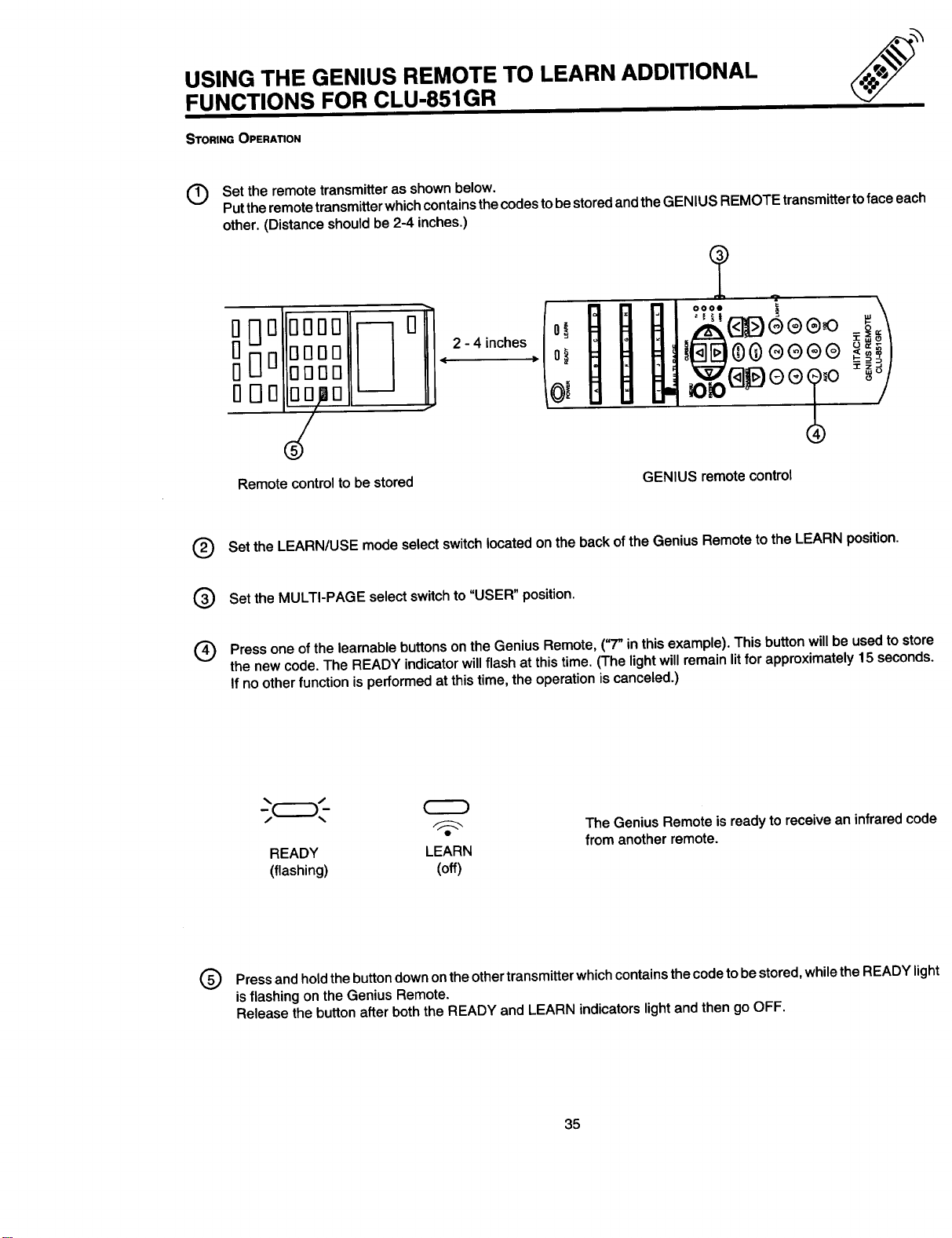
STORING OPERATION
Set the remote transmitter as shown below.
©
Put the remote transmitter which contains the codes to be stored and the GENIUS REMOTE transmitter to face each
other. (Distance should be 2-4 inches.)
D _
DOO
0000
OOOO
0000
0 Off 0
0
2 - 4 inches
0000 !
i
G
Remote control to be stored
Set the LEARN/USE modeselectswitchlocated on theback of theGenius Remoteto the LEARN position.
Set the MULTI-PAGE select switch to "USER" position.
one on
Press of the learnable buttons the Genius in this This button will be used to store
the new code. The READY indicator will flash at this time. (The light will remain lit for approximately 15 seconds.
If no other function is performed at this time, the operation is canceled.)
Remote, ("7" example).
GENIUS remote control
The GeniusRemote isready toreceive an infraredcode
READY LEARN
(flashing) (off)
Press and hold the button down onthe other transmitter which contains the code to be stored, while the READY light
is flashing on the Genius Remote.
Release the button after both the READY and LEARN indicators light and then go OFF.
from anotherremote.
35
Page 36

USING THE GENIUS REMOTE TO LEARN ADDITIONAL
FUNCTIONS FOR CLU-851GR
;CZ:D_,-
READY LEARN
(Goes out) (Lights)
READY LEARN
(Flashing) (Flashing)
Set the LEARN/USE mode select switch on the back of the Genius Remote to "USE" and check that the button to
®
which the code is stored operates correctly. If it does not operate correctly, repeat from step 1.
Repeat steps 3 to 5 to store other keys.
®
TO CLEAR THE STORED CODES FROM THE USER MODE.
Set the MULTI-PAGE select switch to the USER mode and LEARN/USE mode select switch to "LEARN." Then, press the
POWER and the MUTE buttons simultaneously for 3 seconds. The "READY" and "LEARN" LEDs will light together. All
MULTI-PAGE KEYS with codes are reset to their initial states.
To remember stored codes, it is convenient to paste the labels (user's label) provided on the buttons for the USER page.
If the correct labels are not provided, it is possible to write these letters on an empty label with a ballpoint pen.
When storing has been performed correctly, the LEARN
indicator lights for about 2 seconds.
Ifthe storing was not done correctly, or the codes are too
long to learn, or no more codes can be stored in memory
due to memory overflow, the LEARN indicatorand READY
indicator will flash ON and OFF.
POWER READY LEARN
I--_--I I--_1 I-_-I I-_
[I" II oJl c Jl oI]
[IE IIF II o II . I]
_ MULTI PAGE
iiii
MENU
_ 0
_0
36
USER'S LABEL
Page 37

USING THE REMOTE TO LEARN ADDITIONAL FUNCTIONS
NOTE:
1. TooperateyourTV,be suretopointtheGeniusRemoteat theremotesensoronthetelevision.To operateother
electronicequipmentlikea VCR, pointthe remoteatthe sensoronthedevice.
2. Refer to theinstructionmanualofthe VCR for operationonthe buttonsexclusivelyfor theVCR.
3. Be suretokeep theoriginalremotetransmittereven afterstoringitscodesinthe GeniusRemoteControl.
4. IftheGeniusRemoteisleftwithitsbatteriesremoved,thelearnedcodesinits memoryareerasedandwillhave
tobe reprogrammedintothe memory.
5. The Genius RemoteControlmay notbeable to learncertainspecialremotecodes.
iCAUTION ON BATTERIES:
1,
The Genius Remote Control is working when the LEARN indicator lights up when a button is pressed.
2.
When you press a button and the learn indicator will not light up or if the operation is extremely slow, this is an
indication that the batteries should be replaced.
3.
Even if the batteries seem dead, do not remove them until you have replacement batteries ready to put in. The
codes stored in memory will be erased in a few minutes without power. When replacing batteries, prepare the
new ones first.
37
Page 38

EASY GRAPHIC GUIDE
Press MENU onthe Remote Control to display the different features on your HITACHI TV. The feature to be selected
®
will be highlighted in a magenta (purple) color.
Press the CURSOR buttons to highlight a different feature.
®
Press ENTER on the Remote Control to select a feature.
®
I NOTE: Press the CURSOR buttons first to view FAVORITE CHANNELS (See Page 43.)
MENU
CURSOR
PROGRAM VIDEO
This part of the screen shows
that selections are available.
3,
I
RESET
CLOCK
AUDIO
D
_oooooooooooooooooooooeoooeooooooooooooeooooo¢
This part of the screen shows which
Remote Control buttons to use.
NOTE: For CLU-692GR and CLU-691GR, slide MULTI-PAGE select to MENU/CAW mode to work on MENU,
ENTER, and cursor up, down, left and right. Slide to TV mode to use channel • ,V buttons or number
buttons.
>
4AI_ ENTER MENU
• (SET) (EXIT)
J OOOOOO l
38
Page 39

EASY GRAPHIC GUIDE
SET UP
L_?
RESET
PROGRAM
I AIPJCABLE
AIR
I CHANNEL
MEMORY
Return video and audio adjustments to factory settings.
ICHANNEL I Labelchannels IC HILD I Bl°ck channel
CAPTION PAY1,ABC,etc. LOCK picture&sound.
IPROGRAM I Check channel IVOLUM E I Lower v°lume °n
LIST name, scan, I CORRECTION selected channels.
Select antenna I AUTO I First time setup
or cable TV. I PROGRAM forchannelbuttons.
I Channel buttons, I CLOSED I Feature to display
add or erase. ICAPTION dialogue/text.
childlock.
CLOCK ICLOCK Set before using I ON/OFF Turn IV ON or OFF
SET timer features. I TIMER one time or daily.
I.OTO..T,CISet'°r°neI.OTO..T,CISe"°r°ne
MESSAGE-1 time or daily. MESSAGE-2 time or daily.
VIDEO
Adjust Contrast, Color, Tint, Brightness, Sharpness and White Control.
AUDIO
I PREFERENCE
ADJUST
I Adjust balance, IPREFERENCE I Improve sound
bass, and treble. ISETTING I performance.
Special sound effects.
SURROUND
39
Page 40

SET UP
i
SET UP
Select SET UP when setting your TV up for the first time, Use the CURSOR UP/DOWN buttons
on the Remote Control to highlight the function desired.
MENU
41_ ENTER MENU
I AIPJCABLE
AIR
t CURSOR
(SET) (EXIT)
Select CATV if you have cable TV.
I elect AIR if you are using an indoor or outdoor antenna.
I_T I CURSOR
CHANNEL CLOSED I_11_ L_
MEMORY CAPT ON
41_ ENTER MENU
AUTO
(SET) (EXIT)
I /1 [] r_ENTER[ PROGRAM I
i
C2
,GI.
Press the CURSOR buttons to highlight the correct AIR/CABLE mode and press MENU to exit.
Your choice will be shown on the display.
Your selection
is shown here
l CHANNEL CLOSEDI
MEMORY { CAPT ON
_1_ ENTER MENU
AUTO
PROGRAM
(SET) (EXIT)
AIR/CABLE
MENU
(EXIT)
Reception channels for each mode are shown
at the right.
Refer to your cable or TV guide for channel
identification standards.
If certain CA-rV channels are poor or not pos-
sible in the CATV1 mode, set AIR/CABLE to
CArV2.
AIR
VHF 2 - 13ch
UHF 14 ~ 69ch
40
RECEPTION BAND
CAIV 1 or CATV 2
CATV CHANNEL
VHF 2 ~ 13
Mid band A ~ I
A-5 ~ A-1
Super band J ~ W
Hyper band
W+l ~W+28
Ultra band
W+29~W+84
Indicated
on the screen
2~13
14 ~ 22
95 ~ 99
23 ~ 36
37 -64
65 - 125
Page 41

SET UP
AUTO
PROGRAM
TA'R/CABLE1AUTO
AIR PROGRAM
CHANNEL I CLOSED
MEMORY (_APTION
,_ ENTER MENU
(SET) (EXIT)
This feature will automatically store active TV channels in CHANNEL MEMORY. This will allow you
to skip over unused channels when using the CHANNEL UP (A) or DOWN ( • ) buttons.
CURSOR
I '1 r ENTER
C22
AUTOPROGRAM
PRESS ENTER TO BEGIN
MENU
(EXIT)
ENTER
CHANNEL 05
NOW AUTOPROGRAM
IS IN PROGRESS
After Operation
If the MENU button is pressed while the auto programming function is engaged, programming will stop.
See CHANNEL MEMORY to add or erase additional channels.
C2
CHANNEL MEMORY
ADD
NEXT CHANNEL: CH& CH •
• • (EXIT)
i
AIR/CABLE AUTO
AIR PROGRAM
CHANNEL ICLOSED I
MEMORY CAPT ON
,,_ ENTER MENU
(SET) (EXIT)
CURSOR
ENTER
CHANNEL MEMORY
[_NNEL 05
ERASE
NEXT CHANNEL:CH& CHV
• • (EXIT)
MENU
CURSOR CHANNEL
CHANNEL 05
MENU
CHANNEL • ,• buttons. Your Choice will be highlighted in magenta.
CHANNELMEMORY
AIR/CABLE
AIR
,,_ ENTER MENU
(SET) (EXIT)
I se this function after AUTOPROGRAM to add or erase additional channels by the Remote Control
CURSOR
CHANNEL MEMORY
CHANNEL 05
ADD
NEXT CHANNEL: CH • CH •
4 • (EXIT)
CLOSED
CAPT ON
CURSOR
CHANNEL MEMORY
NNEL 05
ERASE
NEXT CHANNEL: CH • CH •
• • (EXIT)
MENU
MENU
Add or erase additional channels while still in CHANN EL MEMORY using the CHANNEL •,• buttons or number buttons
and then add or erase using the CURSOR _1, • buttons.
41
Page 42

SET UP
ICLOSED
CAPTION
The selected function will be in magenta. Your choice for the function will be in blue.
DISPLAY: ON/OFF is to turn the cc display "ON" or "OFF".
MODE: C.C. (Closed Caption) is for the program you are viewing.
video which are displayed on the TV screen. Your local TV program guide denotes these programs
I Closed captions are the dialogue, narration, and/or sound effects of a television program or home
as r_ or _].
CURSOR
AIR
[CLOSED l!
tCAPTION I
,_ ENTER MENU
(SET) (EXIT)
CLOSED CAP,=T.L0_
DISPLAY :ON __
MODE :F_c._t,,_III
CHANNEL:Iml 2
,,_ MENU
(EXIT)
MODE: TEXT is for additional information such as news reports or a TV program guide. This information covers the
entire screen and viewing the TV program is not possible. TEXT may not be available with every I'_ program.
CHANNEL: 1 is used for the primary language (usually English).
CHANNEL: 2 is sometimes used for a second language (may vary by region).
Use the CURSOR • or • to highlight the function to change, press ENTER to change the function, and press MENU
to exit.
• | --
C.C. Selected Text Selected
NOTE:
The word MUTE will not be displayed if the DISPLAY is "ON". If you do not have sound, make sure MUTE
is not set, or Int. speaker in on "OFF"
42
I
Page 43

.VO..TOC....OLS i;'
The FAVORITE CHANNELS function will allow you to select up to 16 favorite channels by pressing the cursor buttons.
CURSOR _jr_ 35
CHANNEL I _ I-"-I [_ [_
_ r---I [_] r_l r---I
-lr-7_r_r --7
_J IACTION
I NEXT CHANNEL:CH& CHV
/ =& ENTER MENU
/ "-" (SET) (EXIT)
ENTER
O
t r--I E=3r--7
::z] r--1 i--'l r_l
E_ r---I r-'-I _
r_l r--1 i---1r_l
ACTION
NEXT CHANNEL:CH& CH •
<1_ ENTER MENU
i (SET) (EXIT)
Use the CHANNEL • ,V or number buttons to select one of your favorite channels.
Use the CURSOR buttons to select the location (in magenta color) for your favorite channel.
Press ENTER to save the channel location.
Enter channel 00 to erase a favorite channel.
35
35 50 02 15
21 11 07 99
02 14 31 98
"lib
NEXT CHANNEL:CH • CH •
,_ ENTER MENU
• (SET) (EXIT)
ENTER
O
v I 50 02 15
37 27 04 i---I
21 11 07 99
02 14
CH SET
Highlight ACTION and press ENTER to use your favorite channels.
Use the CURSOR buttons to highlight a favorite channel and the TV will automatically tune to the channel.
Highlight CH SET and Press ENTER to add or erase more favorite channels.
43
Page 44

RESET
-RESET-
CURSOR
MENU_O
Use the reset to change your preferred video and audio adjustments to factory settings.
PRESS ENTER TO R_I.'I'LIRN
VIDEO AND AUDIO
TO FACTORY SETTINGS
ENTERS, MENU
(SET)" (EXIT)
ENTER
Factory Settings:
VIDEO AUDIO
Contrast: IIIIIIIIIIIMIIIMfllIll Balance: ,,,,,,..,,l,,,.,,m,,.
Color: iiiiiiIiiii nllDillllllllllll I Bass: IIIIIIIIIIIIIIIIIIIIIIHnllll I
Tint: iiiiinllllllllllllUllllllillI Treble: iiiinlllllllllllllllnlllllll
Brightness: ,,,,hi,,,,,,,, MTS Mode: STEREO
Sharpness: ....,..I......., Dynamic Bass: OFF
White Control: ON Loudness: OFF
Internal Speakers: ON
Surround: OFF
I NOTE: This RESET Selection will not change your preferred adjustments. To change back to your adjustments. I
see VIDEO page 50 or AUDIO page 51.
EN]JER) MENU
(SET) _ (EXIT)
Yourpreferedvideo
adjustmentsarenowset.
I
44
Page 45

PROGRAM
This selection contains advanced features which will make TV viewing easier and more enjoyable.
[]
CHANNEL CHILD
CAPTION LOCK
E_ IVOLUME I
{CORRECTION{
4:1_ ENTER MENU
(SET) (EXIT)
CHANNEL
CURSOR
CURSOR
ENTER/1
ENTER MENU
(SET) (EXIT)
Use this feature to give to up 30 channels names for each antenna source.
CAPTION
[]
C_NEL I ]CHILD
CAPTION I I LOCK
PROGRAM I ,VOLUME
LIST ICORRECTION
ENTER MENU
(SET) (EXIT)
ENTER
_ 41
CHANNEL CAPTION
"" (CANCEL)
NEXT CHANNEL: CH • CH •
ENTER MENU
(SET) (EXIT)
CHHHHHHHHHH_ELCURSOR
- A _ I%_ENTER
PAY1 41
NEXT CHANNEL: CH • CH •
Pressthe CURSOR •, • to selectletters.
Pressthe CURSOR ,, • to changeposition.
PressENTER toset the CHANNEL CAPTION and it willappear inthetop leftcornerofthe screen.
PressCHANNEL • ,• or thenumberbuttonsto selectand labeladditionalchannels.
PressMENU toexit.
CHANNEL CAPTION
PAY1 (CANCEL)
ENTER MENU
(SET) (EXIT)
The (*) representsa blankspace.
SelectCANCEL to erase a CHANNEL CAPTION.
I PROGRAM
LIST
CHANNEL CHILD
CAPTION LOCK
PROGRAM IVOLUME
L ST ICORRECT ON
,l_ ENTER MENU
I This function allows you toview whichchannels are labeled in CHANNEL CAPTION (NAME), whicl"have been added to CHANNEL MEMORY (SCAN), and which are protected by CHILD LOCK
(LOCK).
ENTER
--->0---->
(SET) (EXIT)
PressCURSOR • ,• to review morechannels.
PressMENU toexit.
CH NAMESCAN LOCK
01 ........
02 CBS ON
03 VCR ON ON
04 NBC ON --
05 WXYZ ON --
• MENU
• (EXIT)
45
CURSOR
CH NAMESCAN LOCK
06 JAYS ON --
07 JEKO ON
08 ROLY ON ON
09 TESS ON ON
I0 ....
• MENU
• (EXIT)
Page 46

Ic"''° i
LOCK
PROGRAM
This function will block out the picture and sound of the selected channel.
[]
CHILD
LOCK
PROGRAM IVOLUME
LIST IC_)RRECTION
ENTER MENU
(SET) (EXIT)
ENTER
[_ CHILD LOCK 41
LocKI . NCE'KEYNUMBER,,
NEXT CHANNEL: CH& CH •
KEY NUMBER: 0 -9
,_ ENTER MENU
(SET) (EXIT)
The codetoset orcancelCHILD LOCKis a threedigitkey number.The factory presetkeynumberis000.
41
MENU
NEXT CHANNEL:CH& CHV
KEY NUMBER:O-9
l&L ENTER MENU
y (SET) (EXIT)
41
CHILD LOCK
CHILDLOCK IKEY NUMBER1
CANCEL I MENU
NEXT CHANNEL: CHak CHV
KEY NUMBER: 0 -9
41 Ib (EXIT)
ICHANGE I
000
The picture and sound will now be blocked out for this channel. Repeat the same steps to cancel the CHILD LOCK.
To changethe keynumber,selectkeynumberchange.Entertheold number(factorypreset000 for firsttime use),then
entera newthree digitkey numberyouprefer.
Ifyouforgetyourkey number,usethe factorycode777 to erase yourkey number.Thiswill resetthe key
numberbackto thefactory preset000.
46
Page 47

PROGRAM
I VOLUME
CORRECTION I
[]
CHANNEL CHILD
CAPTION hOCK
PROGRAM I WOLUME
LST I ICORRIECT ON
Use this function to reduce the volume level of up to four TV channels that sound loud compared
to other TV channels.
ENTER MENU
{SET_ (EXIT)
I_ LEVEL 18
NEXT CHANNEL:CH& CHV
41_ ENTER MENU
100%
100%
100%
100%
(SET / (EXITI
CHANNEL
Pressthe CURSOR A, Vto selectone ofthe fourvolumecorrections.
Usethe CHANNEL• ,V or numberbuttonstoselecta channel.
I_ LEVEL 22
NEXT CHANNEL: CH& CHV
_l_ ENTER MENU(SET) (EXIT)
100%
100%
100%
100%
22
ENTER
0-->
[_ CH LEVEL
II 100%
1oo%
100%
100%
NEXT CHANNEL: CH& CH •
41_ ENTER MENU
(SET) (EXIT)
22
CURSOR
[_ CH LEVEL
ii iIII
lOO%
100%
100%
NEXT CHANNEL: CH • CH •
,l_ ENTER MENU
(SET) (EXIT)
Press ENTER to set the channel.
Press the CURSOR,_, I_ to adjust volume level.
Press MENU to exit.
NOTE: 1.2oVOLUME CORRECTION adjustment is for the channel displayed inthe top right corner of the screen.
To adjust a different channel, you must select the channel with the channel or number buttons and
press ENTER.
Ifthe channelhasbeencorrectedbefore,use thecursor• ,V to highlightthat channelthen
usethe cursor,_, _ to changethe level.
3. To erase a channel from the volume correction, select channel 00 and press ENTER.
4. The volume level will change from 50% to 100% in 5% steps.
47
Page 48

Q
CLOCK
CLOCK
I CLOCK
SET
Use this feature for all time related functions.
I The time must be set before you can use the ON/OFF TIMER or AUTOMATIC MESSAGE.
CURSOR
o
Use the NUMBER buttons and CURSOR ,<, •to set the time.
The AM or PM selected will be highlighted in blue.
[]
i# ocK o .oFF
AUTOMATIC AUTOMATIC
MESSAGE-1 MESSAGE-2
PLEASE CLOCK SET
AT THE FIRST TIME
il_ ENTER MENU
T MEn
(SET) (EXIT)
ENTER
[]
CLOCK SET
I-: o- i PM
HOUR: 01-12
ENTER
(START)
MENU
(EXIT)
ON/OFF
TIMER
[]
__ ION/OFF I
AM__ IAUTOMATIC I
SAGE-11 IMESSAq_E-2 I
ENTER MENU
(START) (EXIT)
I This function will automaticallly turn the TV ON or OFF, one time only or everyday.
ITIMER I
ENTER
[]
ON TIME: --:-- AM PM
OFF TIME: --:-- AM PM
ON CHANNEL: --
MODE: OFF ONCE DALLY
CANCEL
HOUR: 01 - 12
• ENTER MENU
• (SET) (EXIT)
CURSOR
[]
ONT,ME:0,:00
OFF TIME: 09:00
ON CHANNEl.: 39
MODE: OFF ONCE llil
CANCEL
• ENTER MENU
• (START) (EXIT)
The step to change will be in magenta.
Press the number buttons to select the time the TV will turn "ON" or "OFF". (AM: 1, PM: 2)
Press the CURSOR "4, • buttons for MODE: ONCE (one time only) or MODE: DAILY (TV will turn ON/OFF at the same
time every day).
Press CHANNEL • ,Y or the NUMBER buttons to set the channel the TV will tune to when it automatically turns ON.
Your choice for AM/PM and MODE will appear in blue.
Press ENTER to start.
Sele,_ CANCEL and press ENTER to erase time.
I NOTE: You either "ON" time "OFF" time both. The mode will be the for both. I
can set
only, only,
or same
I z_CAUTION: Do not use your TV as a deterrent when away from home by using both the ON and OFF
TIMERS. For safety, the TV should be turned OFF when you are away from home.
48
Page 49

CLOCK
I AUTOMATIC
Use this function to set one or two personal messages every day or one time only.
MESSAGE
[]
CLOCK ] ON/OFF
SET TIMER I
AUTOMATIC I AUTOMATIC
MESSAGE-I MESSAGE-2
PLEASE CLOCK SET
AT THE FIRST TIME
'!_ ENTER MENU
(SET) (EXIT)
ENTER
[]
MESSAGE-1
*********************
*********************
(CANCEL)
ENTER MENU
(SET) (EXIT)
Use the CURSOR A, • to select a letter orothercharacter.
Use the CURSOR <1,I_ tochange position.
CURSOR
MESSAGE-1
DO YOUR HOMEWORK OR
I WILL USE CHILDLOCK
(CANCEL)
<1_ ENTER MENU
(SET) (EXIT)
PressENTER when messageis finished.
The asterisk(*) representsa blankspace.
Movethe CURSOR <1,, until(CANCEL)is magentaandpress ENTERto erasemessage.
[]
MESSAGE-1
REMEMBER TO TAKE
DALLY VITAMINS
(CANCEL)
,_ ENTER MENU
(SET) (EXIT)
Use the CURSOR A,Yto choose MODE or TIME.
Use the CURSOR 4, , to set MODE when it is magenta. Your choice will be in blue.
Use the NUMBER buttons to set the time.
Press ENTER to start and MENU to exit.
ENTER
[]
MESSAGE-1
REMEMBER TO TAKE
DAILY VITAMINS
_ ONCE DAILY
TIME: --:-- AM PM
ENTER MENU
(SET) (EXIT)
CURSOR
I NOTE: AUTOMATIC MESSAGE-2 isthe CURSOR operation.
same
49
Page 50
VIDEO
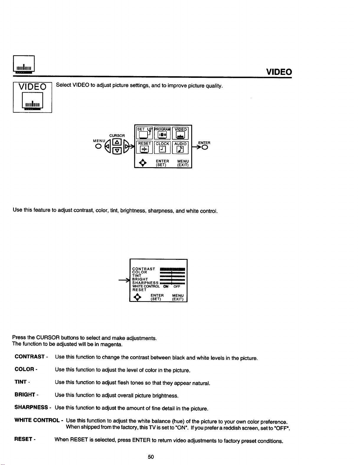
VIDEO
Select VIDEO to adjustpicture settings,and to improvepicturequality.
CURSOR
ENTER
-->O
ENTER MENU
(SET) (EXIT)
Use this feature to adjust contrast, color, tint, brightness, sharpness, and white control.
CONTRAST
COLOR -+
TINT ;' _ _ _:
BRIGHT .............
SHARPNESS
WHITE CONTROL OFF
RESET
_1_ ENTER MENU(SET) (EXIT)
Pressthe CURSOR buttons to selectand makeadjustments.
The function to be adjustedwillbein magenta.
CONTRAST - Use thisfunction tochangethecontrastbetweenblackandwhitelevelsinthe picture.
COLOR - Use thisfunction toadjustthelevelofcolorin thepicture.
TINT - Usethisfunction toadjustflesh tonessothat theyappear natural.
BRIGHT - Usethisfunction to adjustoverallpicturebrightness.
SHARPNESS - Use thisfunction to adjustthe amountof fine detail inthepicture.
WHITE CONTROL - Use thisfunction to adjustthewhitebalance(hue)ofthe pictureto yourown colorpreference.
Whenshippedfromthefactory, thisTV issetto"ON". Ifyoupreferareddishscreen,setto "OFF'.
RESET - When RESET is selected,pressENTER to returnvideoadjustmentstofactory presetconditions.
50
Page 51

AUDIO
AUDIO
I PREFERENCE I Use this to set balance, bass, and treble.
ADJUSTMENT
Select AUDIO to adjust the TV to your preference, to improve the sound quality, and to
select special sound effects.
CURSOR
,l_ ENTER MENU
(SET) (EXIT)
I
CURSOR
[]
l s_s0-_ I
,_ ENTER MENU
(SET) (EXIT)
[]
I SURROUND ]
ENTER MENU
(SET) (EXIT)
ENTER
-->C_-)
[]
BALANCE iilallll_lklalauu_
BASS
TREBLE mm_
RESET
'!_ ENTER MENU
(SET) (EXIT)
Press the CURSOR buttonsto selectand make adjustments.The function tobe adjustedwillbe inmagenta.
BALANCE - Thisfunctionwillcontroltheleftand rightbalanceofthe"IV internalspeakers,theaudiotohi-fioutput,and
the surroundspeakers.
BASS-
TREBLE-
RESET-
This function controls the low frequency audio to all speakers.
This function controls the high frequency audio to all speakers.
When RESET in selected, press ENTER to return audio adjustments to factory preset conditions.
51
Page 52

AUDIO
IPREFERENCE
SETTING
Use the CURSOR •,Vto select a function. The function will be in magenta.
Use the CURSOR ,. I_ to change function. Your choice will be in blue.
MTS MODE (Multi-Channel Television Sound) will allow you to select STEREO (a stereo broadcast), SAP (second audio
program) which may be a secondary language, weather report, etc. or MONO (monaural sound) used when receiving
a weak stereo broadcast.
Use Preference SETTING to improve the sound performance of your TV depending on listening
conditions.
L
[]
PREFERENCB PREFERENC_
ADJUST / SETTING I
[ SURROUND ]
,_ ENTER MENU
(SET) (EXIT)
ENTER
-->O--->
[]
MTS:MONO SAP
LOUDNESS: ON
INT. SPEAKERS:_ OFF
MENU(EXIT)
The sources received will be displayed below the channel number. The source you select will be displayed to the left of
the channel number. See example below for each selection when both stereo and second audio are received (monaural
is always received).
STEREO SELECTED
NEWS STEREO 31 I
ST/SA
SAP SELECTED MONO SELECTED
NEWS SAP 31 NEWS
ST/SA
31
I
LOUDNESS
This function will improve the quality of both low and high frequency sounds when listening at low volume levels.
INT. SPEAKERS
This function is useful when first setting up the external speakers, or ifyou prefer to use only speakers from a separate
stereo system.
52
Page 53

AUDIO
ISURROUND I he following Surround sound settings will reproduce the "live" sound you would hear in concert
Use the CURSOR buttons to select Surround settings.
halls, movie theaters, etc. when you set up your speaker system as shown in the section on rear
panel connections on page 16 and page 19. The Surround sound system is most effective with
movies played on a stereo VCR.
Surround sound allows the viewer to enjoy sound which provides a feeling of "presence" from stereo
broadcasts and VCR tapes* recorded with stereo sound. Also a mono input, simulating a stereo or
more louder reproduction.
[]
P_FERENCQ
ISEI-FING |
I SURROUND I
,_ ENTER MENU
(SET) (EXIT)
CURSOR
[]
SURROUND
IOFF ] [ MUSIC i
[MOVIE ][SIMULATE I
MENU
(EXIT)
SURROUND OFF
Usethisfor normal stereo/monobroadcasts.
I NOTE: _fthes_undisn_isywhenastere_br_adcastisreceivedandtheTVissett_theSurr_undm_de_decrease J
the "Treble" control or turn the "Surround OFF".
MOVIE SURROUND
Listenerissurroundedbymanysoundsourcessuchas a movietheater reproduction.
I NOTE: Some TV systems do not transmit optimum audio channel separation which can reduce the effectiveness I
of the MOVIE SURROUND function.
MUSIC SURROUND
Resonantsound- Listenerhasthe feeling of being in a concerthall.
Atstereoinput,soundofmusicis changedmorelouder.
SIMULATE SURROUND
At monoInput,soundis changed moreloudlysimulatingastereo like Surround.
* Your play VCR must be a HI-FI or stereo unit. See page 18. For stereo VCR connection.
* Set must be outputting stereo. (See MTS mode: stereo. See page 52.)
53
I
Page 54

CONTRoLCAREOF YOUR HITACHI COLOR TV AND YOUR REMOTE
DO
Dust the screen and cabinet with a soft cloth.
Clean the screen with a softcloth moistened in warm water. Dry with a soft cloth. (A mildsoap may be used ifthe
screen is extremely dirty.)
Placeyour TV and Remote Control away fromextremeheat, humidityand extremelydustyplaces.
Removetheplugfrom the walloutletifyourtelevisionset willnotbe usedfor a longperiodoftime,for instance,
whenyougo onvacation.
DO NOT
Do not clean your screen or cabinet with strong cleaners, polishes or chemically treated cloth.
Do notplace rubber orvinylproductsor cellophanetape onyour set.
Do not touch the screen too often.
DonotsubjecttheRemoteControlto shockssuchasdropping itonthefloor, etc.Physicaldamagetothe precision
partsmay result.
Avoidplacingthe RemoteControlin a highhumidityplace orgettingitwet. Don'tleave iton or near a heater.
Excessiveheator moisturemay causethe unitto cease operation.
When the batteries run down, Remote Control operation will become erratic or possibly stop altogether. Replace
the old batteries with fresh "AA" size batteries.
54
Page 55

RECEPTION PROBLEMS
• IGNITION NOISE:
Black spots or horizontal streaks may appear, pictu re may flutter or drift. Usually caused
by interference from automobile ignition systems, neon lamps, electrical drills and other
electrical appliances.
f
• GHOSTS:
Ghosts are caused by the television signal following two paths. One is the direct path and
the other is reflected from tall buildings, hills or some other objects. Changing the
direction or position of the antenna may improve reception. Ghosting may also be caused
by defects in the antenna system such as unshielded leads or connecting several sets
to the same antenna without using multiple antenna couplers.
• SNOW:
Ifyourreceiverislocatedinthefringeareaofatelevisionstationwherethesignalisweak,
your picturemay be marred by the appearance of small dots. When the signalis
extremelyweak,it maybenecessarytoinstalla specialantennatoimprovethe picture.
• RADIO FREQUENCY INTERFERENCE:
The interference produces moving ripples or diagonal streaks, and in some cases,
causes loss of contrast in the picture.
55
Page 56

CHECK HERE BEFORE CALLING FOR SERVICE
SYMPTOMS
No picture, no sound
Sound OK, picture poor
Picture OK, sound poor
Picture blurred
Lines or streaks in picture
Poor reception on some channels
No color
Poor color
i
NOTES
56
Page 57

SPECIFICATIONS
Features:
• Superfine Picture Quality
650 Lines Horizontal Resolution
• Dark Tint Picture Tube
• Genius Remote
Controls many VCR brands and cable boxes.
• ICONS: Easy Graphic Guide
• Full set of Input Jacks, including S-Video
• Closed Caption Decoder
• Picture-in-Picture (27UX5B/27CX4B/27CX3B)
• Comb Filter, Wide-Band Video-Amp and White Control
• MTS (Multi-Channel Television Sound) Stereo Broadcast Reception
• 3D Surround Sound (3 Way)
• SES - Spatially Equalized Sound (Except 27CX3B)
Screen Size: 27V (27 inches measured diagonally)
Inputs:
• Power Input ..................... AC 120V, 60 Hz
• Powerconsumption(ave.) ................... 116W
• Power consumption (max.) ................. 155W
• Antennainputimpedance................... 75 Ohm
• Channel coverage ....................... 181 ch.
VHF-Band ............................... 2~13
UHF Band.............................. 14~69
CAI-V Mid Band ....................... A-5~A-1
Super Band ............................ J-W
Hyper Band...................... W+1-W+28
Ultra Band...................... W+29-W+84
• Video......................... 1.0Vp-p,75 Ohm
• S-Video
Luminance(Y)................. 1.0Vp-p,75 Ohm
Chrominance(C).............. 0.286Vp-p,75 Ohm
• Audio input impedance .................... 47k Ohm
• Average input level ................... 470mVrms
• Maximum input level .................. 940mVrms
Outputs:
• Video ............................ 1.0Vp-p,75 Ohm
• Audio (fixed) ................... 0~470mVrms, 1kOhm
Dimensions:
27UX5B 27CX4B
• Height (in.)... 231/3= 231/3=
• Width (in.)... 271/4 271/4
• Depth (in.)... 203116 203/1e
• Weight (Ibs.)... 88.0 88.0
27CX3B
• Height (in.)... 231/3=
• Width(in.)... 271/4
• Depth(in.)... 20311o
• Weight (Ibs.)... 88.0
I NOTE: Due to improvements, specifications in this operating guide are subject to change without notice. ]
57
Page 58

HITACHI
To locate an authorized
HITACHI service facility
in the continental U.S.A.
DIAL TOLL FREE
7 days a week, 24 hours a day
1-800-448-2244
Hitachi Home Electronics (America), Inc.
Hitachi has made every effort to assure you hours of trouble free operation from your unit. However, should you
require service, a network of Hitachi Authorized Service Facilities has been established in all 50 states and Puerto
Rico. Each facility will provide you with convenient and expedient assistance. Our service "Hotline" operator will
direct you to the Hitachi Authorized Service Facilily nearest you. Just present proof of purchase and/or delivery
receipts Io the H_lachi Authorized Service Facility, and service will be rendered in accordance with the terms of the
Iimil:ed warranty as stated on your warranty card or operating guide.
Should you have any questions regarding in-warranty service, operation or technical assistance,
please contact:
Hitachi Home Electronics (America), Inc.
:3890 Steve Reynolds Blvd.
Norcross,GA 30093
Tel:404-279-5600
Hitachi Sales Corporation of Hawaii
:3219 Koapaka St. / Honolulu, HI 968'19
Tel:808-836-3621
58
Page 59

INDEX
AC(_Od0_ ........................ 6
Anienna .................. 8,9,13,15,40
Atdo
P._em_ A_Wst ................. .51
_Seunj ................. .52
Sam'oood.................... 19,53
A,zxEoIo FE.-R................... 15,, 16, 19
Az_TioSyslem Set-Up .................. 19
AVX......................... lO, 11
Ba_ F1eplacemealt................. 7.54
C,ab0eBoxCodes.................. 32,33
_ Hook,p .................... .9
Care foi'your TV and Flemole .............. ..54.
CATV ................... 4.8,31.32,,33
Char,rid....................... 11,26
C_odnoS_mdCodes.................
Ck_k
X_oma_Mossage.................
Qocksot ..................... 48
(:_ I_nor ................ 25,48
COlmOcrmn_
Xnlonna ..................... 4,9
Front Panol ................... 12
Rear Pam_ ............. 15,16, 17,18, 19
...................... .26, 43
Easy_G.k_e ................. 38.39
ENTER ....................... .2S,43
EXCHNG ........................ .20
F-C(]EtlM_K)r ....................... .9
FAVORITE CHANNELS ................. 43
......................... .29
Front _ Conlirols ............... 10.11.12
_ Saiogua_s............... .2,_,4
Jaci_
_ Panel ............... 15,16, 17.18
FflOlll:Pard ................. 12, 13., 14
Leam In(Ecabor .............. 20. 341.,,33,, 36
t..EAFUWtCSESm'_h ............. 20.34.35,36
LIGHT OuUon.................. 26°22.27
L.ocarmn,,'VZe_dng................. 3,,6,,54
LST-CH ......................... .27
.......................... .,26
IMoMe Soi'emmd ................... 19.53
Mono_ ....................... 53
Moil-pa0e.................... 26,21,22
Music Simmmd .................. 19,53
P IN P (Piclure in Picb,.e) ........... 5. 27. 28. 2_,
_ Conne(::tor .................... _,
Rll:dua'eCauldmlS.....................
Power
Lig_ BuUon................ _,22. _
B_ ........................ _:'_
Cha.,rm_Cap_k_................... ._
Lock ..................... 446
List. ...................
VotkJmeC(]mre(:df_ion................ 47
Ready Indlk:akx ................ 31.32, 33. 36
RECALL .........................
Band ........................ 44_
.................... 55
_ C,onlxlol
C,aldle Box FunlClbk:ms............... .31
L.ean'd_ Funclk)m ............... .34
_ in Pi0U'e .................. 26
Sensor ........................ 11
TV Funcldoris............... ..25.26.27
VCR_ .................. 30
RESET .................. 3S.,5O,,44_5O,51
S-Video ..................... 9. 13, 14,,15
Safe_ Tqps. .................... .2.,3,4
SA,,SAJP....................... :_,52
...................... .,,,_:)o31
,,'_01i_Sw,Jcl_ .................. 20,30,31
__ .................... .5_
Sense ........................ .4,59
SETUP
AI_ .................... 40
_._o P,ogram................... 41
Cha_ea Momo_y................. 41
Closed _ .................. 42
SHIFT .......................... 29
S_razJdla_Swround .................. 19.53
Speomcazkms...................... S7'
Sk_,g Codes ......................
Twin Lead _ .................. 9
UFiF,NI'f ....................... 9, 15
VCR Codes ..................... .32.,33
Vkdeo ........................... .50
Volome ....................... 11.27
5O
Page 60

HITACHI
QR00921
 Loading...