

Page 1
SOLID STATE COLOR TV
OPERATING GUIDE
S
IMPORTANT SAFEGUARDS
FIRST TIME USE
THE REMOTE CONTROL
COLOR GRAPHIC GUIDE
USEFUL INFORMATION
2-5
6-24
25-37
38-55
56-63
INDEX
Page 2

Follow all warnings and instructions marked on this television receiver.
The lightning flash with arrowhead symbol, within an
equilateral triangle, is intended to alert the user to the
presence of uninsulated "dangerous voltage" within the
RISK OF ELECTRIC SHOCK
DO NOT OPEN
product's enclosure that may be of a sufficient magnitude
IMPORTANT
constitute a dsk of electdc shock to persons.
CAUTION: TO REDUCE THE RISK OF ELECTRIC SHOCK,
DO NOT REMOVE COVER (OR BACK)
NO USER SERVICEABLE PARTS INSIDE
REFER SERVICING TO QUALIFIED SERVICE PERSONNEL.
A The exclamation point within an equilateral tdangle is
• IL. intended to alert the user to the presence of important
J _. operating and maintenance (servicing) Instructions In the
_ _, literature accompanying the appliance.
i
WARNING:
TO PREVENT FIRE OR SHOCK HAZARD, DO NOT
EXPOSE THIS TELEVISION SYSTEM TO RAIN OR MOISTURE.
NOTE: There are no user serviceable parts inside the receiver.
Model Number and Serial Number are indicated on back side of the set.
POWER SOURCE
This HITACHI COLOR TV is designed to operate on 120 volts 60Hz, AC household current.
Insert power cord into a 120 volt 60Hz outlet.
TO PREVENT ELECTRIC SHOCK, DO NOT USE THE TELEVISION'S PLUG WITH AN EXTENSION
CORD, RECEPTACLE, OR OTHER OUTLET UNLESS THE BLADES AND GROUND TERMINAL CAN
BE FULLY INSERTED TO PREVENT BLADE EXPOSURE.
NEVER CONNECT THE TV TO 50 Hz, DIRECT CURRENT, OR ANYTHING OTHER THAN THE SPECI-
FIED VOLTAGE.
This television receiver will display television Closed Captioning, ( B or I_ ), in accor-
I NOTE:
dance with paragraph 15.119 of the FCC rules.
Never remove the back cover of the set as this can expose you to very high voltages
and other hazards. If the set does not operate properly, unplug the set and call your
I _CAUTION:
dealer or service shop.
2
Page 3
IMPORTANT
iMPORTANT SAFEGUARDS
CAUTION: SAFETY POINTS YOU SHOULD KNOW ABOUT
* Read all of these instructions YOUR HITACHI TELEVISION RECEIVER
* Save these instructions for later use.
* Follow all warnings and instructions marked
on the television receiver.
)ur reputation has been built on the quality,performance, and ease of service of HITACHI television receivers.
Safety is also foremost in our minds in the design of these units. To help you operate these products properly,this section illustrates safety tips which will be of
benefit to you. Please read it carefully and apply the knowledge you obtainfrom it to the proper operationof your HITACHI television receiver.
Please fill out your warranty card at once and mail it to HITACHI. This will enable HITACHI to notifyyou promptly inthe improbable event that a safety problem
should be discovered in your model of product.
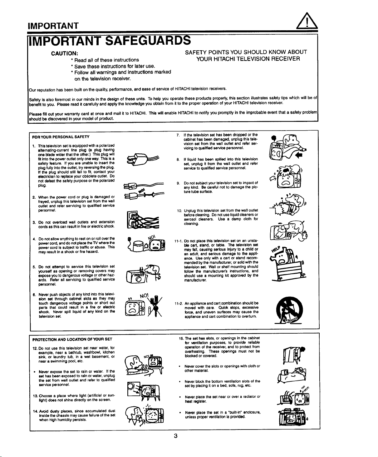
FORYOUR PERSONAL SAFETY 7.
1. This television set is equipped with a polarized
alternating-current line plug (a plug having
one blade wider that the other.) This plug will
fit into the power outlet only one way. This is a
safety feature. If you are unable to insert the
plug fully into the outlet, try reversing the plug.
If the plug should still fail to flt, contact your
electrician to replace your obsofete outlet. Do
not defeat the safety purpose or the polarized
plug.
2. When the power cord or plug is damaged or
frayed, unplug this television set from the well
outlet and refer servicing to qualified service
personnel.
3. DO not overload wall outlets and extension
cords as this can result in fire or electric shock.
4. Do not allow anything to real on or roll over the
power cord, and do not place the TV where the
power cord Issubjecttotrafficor abuse. This
may resultina shock or firehazard.
5. DO not attempt to service this television set
youraeff as opening or removing covers may
expose you to dangerous voltage or other haz-
ards. Refer all servicing to qualified service
personnel.
6. Never push objects of any kind into this televi-
alin set through cabinet slits as they may
touch dangerous voltage points or short out
parts that could result in a fire or electric
shock. Never spill liquid of any kind on the
television set.
If the television set has been dropped or the
cabinet has been damaged, unplug this tele-
vision sat from the well outlet and refer ser-
vicing to qualified service personnel.
If liquid has been spilled into this television
set, unplug It from the wall outlet end refer
service to qualified service personnel.
9. Do not subject your television set to impact of
any kind. Be careful not to damage the pic-
ture tube surface.
10. Unplug this television set from the wall outlet
before cleaning. Do not use liquid cleaners or
aerosol cleaners. Use a damp cloth for
cleaning.
11-1.
Do not place this television set on an unsta-
ble cart, stand, or table. The television set
may fall, causing serious Injury to a child or
an adult, and serious damage to the appli-
ance. Use only with a cart or stand recom-
mended by the manufacturer, or sold with the
television set. Wall or shelf mounting should
follow the manufacturer's Instructions, and
should use a mounting kit approved by the
manufacturer.
11-2. An appliance and cart combination should be
moved with care. Quick stops, excessive
force, and uneven surfaces may cause the
appliance and cart combination to overturn.
PROTECTION AND LOCATION OFYOUR SET
12. Do not use this television set near water, for
example, near a bathtub, washbowl, kitchen
sink, or laundry tub, in a wet basement, or
near a swimming pool, etc.
,, Never expose the set to rain or water. If the
set has been exposed to rain or water, unplug
the set from wall outlet and refer to qualified
servicepersonnel.
13. Choose a place where light (artificial or sun-
light) does not shine directly on the screen.
14. Avoid dusty places, since accumulated dust
inside the chassis may cause failure of the set
when high humidity persists,
15. The set has slots, or openings in the cabinet
for ventilation purposes, to provide reliable
operation of the receiver, and to protect from
overheating. These openings must not be
blocked orcovered.
• Never cover the slots or openings with cloth or
other material.
• Never block the bottom ventilation slots of the
set by placing it on a bed, sofa, rug, etc.
• Never place the set near or over a radiator or
heat register.
• Never place the set in a "built-in" enclosure,
unless proper ventilation is provided.
Page 4
PROTECTION AND LOCATION OF YOUR SET
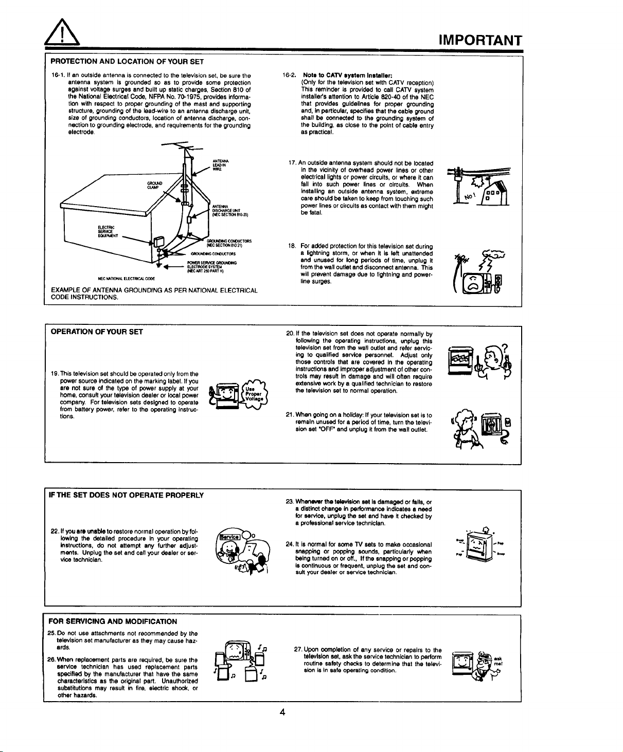
16-1. If an outside antenna is connected to the television set, be sure the
antenna system is grounded so as to provide some protection
against voltage surges and built up static charges, Section 810 of
the National Electrical Code, NFPA No. 70-1975, provides informa-
tion with respect to proper grounding of the mast and supporting
structure, grounding of the lead-wire to an antenna discharge unit,
size of grounding conductors, location of antenna discharge, con-
nection to grounding electrode, and requirements for the grounding
electrode,
,,.=
UNIt
(t,IECSEC'rlO_a10-20)
16-2.
Note to CATV system Installer:
(Only for the television set with CATV reception)
This reminder is provided to call CATV system
installer's attention to Article 820-40 of the NEC
that provides guidelines for proper grounding
and, In particular, specifies that the cable ground
shall be connected to the grounding system of
the building, as close to the point of cable entry
as practical.
17. An outside antenna system should not be located
in the vicinity of overhead power lines or other
electrical lights or power circuits, or where it can
fall into such power lines or circuits. When
installing an outside antenna system, extreme
care should be taken to keep from touching such
power lines or circuits as contact with them might
be fatal.
IMPORTANT
_r:Ct,_:CTrON8_0211
EXAMPLE OF ANTENNA GROUNDING AS PER NATIONAL ELECTRICAL
CODE INSTRUCTIONS.
OPERATION OFYOUR SET
19.This television set should be operated only from the
power source Indicated on the marking label. If you
are not sure of the type of power supply at your
home, consult your television dealer or local power
company. For television sets designed to operate
from battery power, refer to the operating instruc-
tions.
IF THE SET DOES NOT OPERATE PROPERLY
22. If you are unable to restore normal operation by fol-
lowing the detailed procedure in your operating
instructions, do not attempt any further adjust-
ments. Unplug the set and call your dealer or ser-
vice technician.
18. For adeed protection for this television set during
a lightning storm, or when It is left unattended
and unused for long periods of time, unplug it
from the well outlet and disconnect antenna. This
will prevent damage due to lightning and power-
line surges.
20. If the television set does not operate normally by
following the operating instructions, unplug this
television set from the well outlet and refer servic-
ing to qualified service personnel. Adjust only
those controls that are covered in the operating
instructions and Improper adjustment of other con-
trols may result In damage and will often require
extensive work by a qualified technician to restore
the television set to normal operation.
21. When going on a holiday: If your television set is to
remain unused for a period of time, turn the televi-
sion set "OFF" and unplug it from the well outlet.
23. Whenever the television set Is damaged or falls, or
a distinct change in performance indicates a need
for service, unplug the set end have It checked by
a professional service technician.
24. It is normal for soma TV sets to make occasional
snapping or popping sounds, particularly when
being turned on _ off., If the snapping or popping
Is continuous or frequent, unplug the set and con-
sult your dealer or service technician.
FOR SERVICING AND MODIFICATION
25. Do not use attachments not recommended by the
television set manufacturer as they may cause haz-
ards.
26. When replacement parts are required, be sure the
service technician has used replacement parts
specified by the manufacturer that have the ssme
characteristics as the original part, Unauthorized
substitutions may result in fire, electric shock, or
other hazards.
27. Upon completion of any service or repairs to the
television set. ask the service technician to perform
routine safety checks to determine that the televi-
sion is in sate operating condition.
4
Page 5
PI!31UHE CAUTIONS
Continuous On-Screen Displays such as
video games, stock market quotations,
computer generated graphics, and other
fixed (non-moving) patterns can cause per-
manent damage to Color Television
WARNING
Receivers. Such "PATTERN BURNS" con-
stitute misuse and are NOT COVERED by
your Hitachi Factory Warranty.
When using the Picture-in-Picture function, the sub-picture should not be left permanently
in one corner of the screen or a "PATTERN BURN" may develop over a long period of time.
This Color Television Receiver was intended mainly for the private viewing of programs
broadcast by TV stations, cable companies, and programs from other video sources. Public
viewing may require prior authorization from the broadcaster or owner of the video program.
5
Page 6
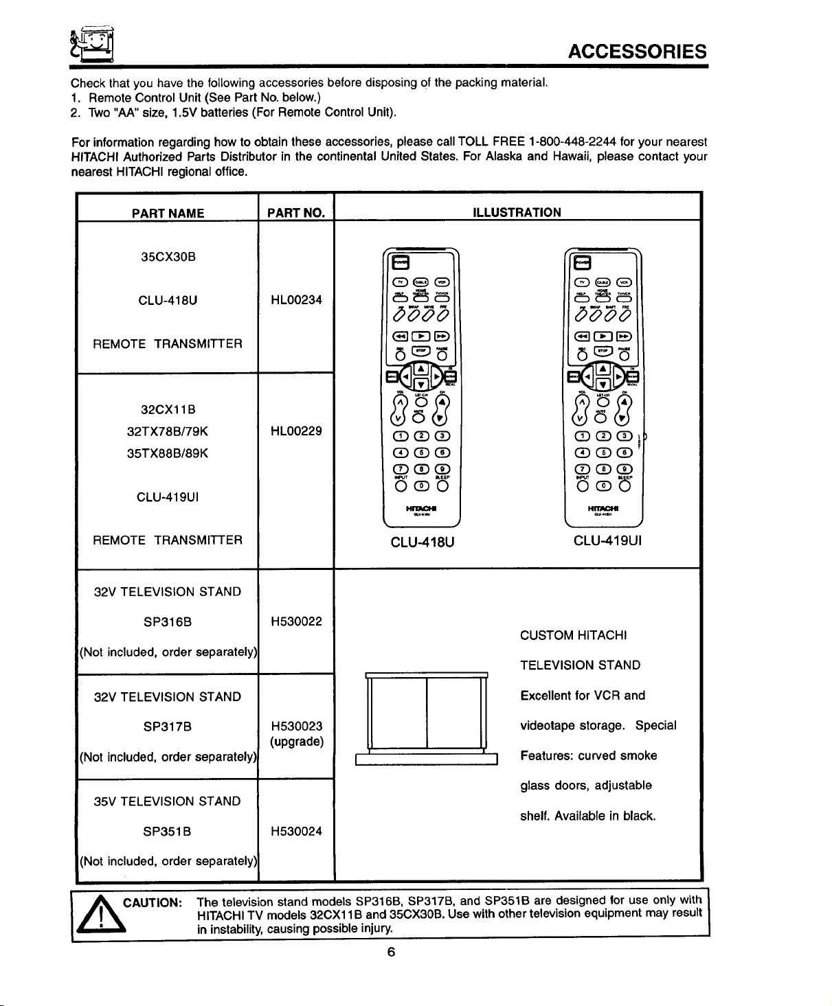
ACCESSORIES
Check that you have the following accessories before disposing 0f the packing material.
1. Remote Control Unit (See Part No. below.)
2. Two "AA" size, 1.5V batteries (For Remote Control Unit).
For information regarding how to obtain these accessories, please call TOLL FREE 1-800-448-2244 for your nearest
HITACHI Authorized Parts Distributor in the continental United States. For Alaska and Hawaii, please contact your
nearest HITACHI regional office.
PART NAME PART NO. ILLUSTRATION
35CX30B
CLU-418U
REMOTE TRANSMITTER
32CXl 1B
32TX78B/79K
35TX88B/89K
CLU-419UI
REMOTE TRANSMITTER
32V TELEVISION STAND
SP316B
'Not included, order separately}
HL00234
HL00229
H530022
B
(3_r€3 [E)
(Z) (_ (_
(3DQD (3D
(D (3D(Z)
I_UT _EEP
OQO
• J
CLU418U
"B
(2£)_E_(ED
(_ r-cq lEE)
QD (3D(Z)
O_)QD
CLU-419UI
CUSTOM HITACHI
TELEVISION STAND
32V TELEVISION STAND
SP317B
'Not included, order separately)
35V TELEVISION STAND
SP351B
Not included, order separately]
The television stand models SP316B, SP317B, and SP351B are designed for use only with
CAUTION:
HITACHI TV models 32CXl 1B and 35CX30B. Use with other television equipment may result
in instability, causing possible injury.
H530023
(upgrade)
H530024
Excellent for VCR and
videotape storage. Special
r-
Features: curved smoke
glass doors, adjustable
shelf. Available in black.
I
6
Page 7
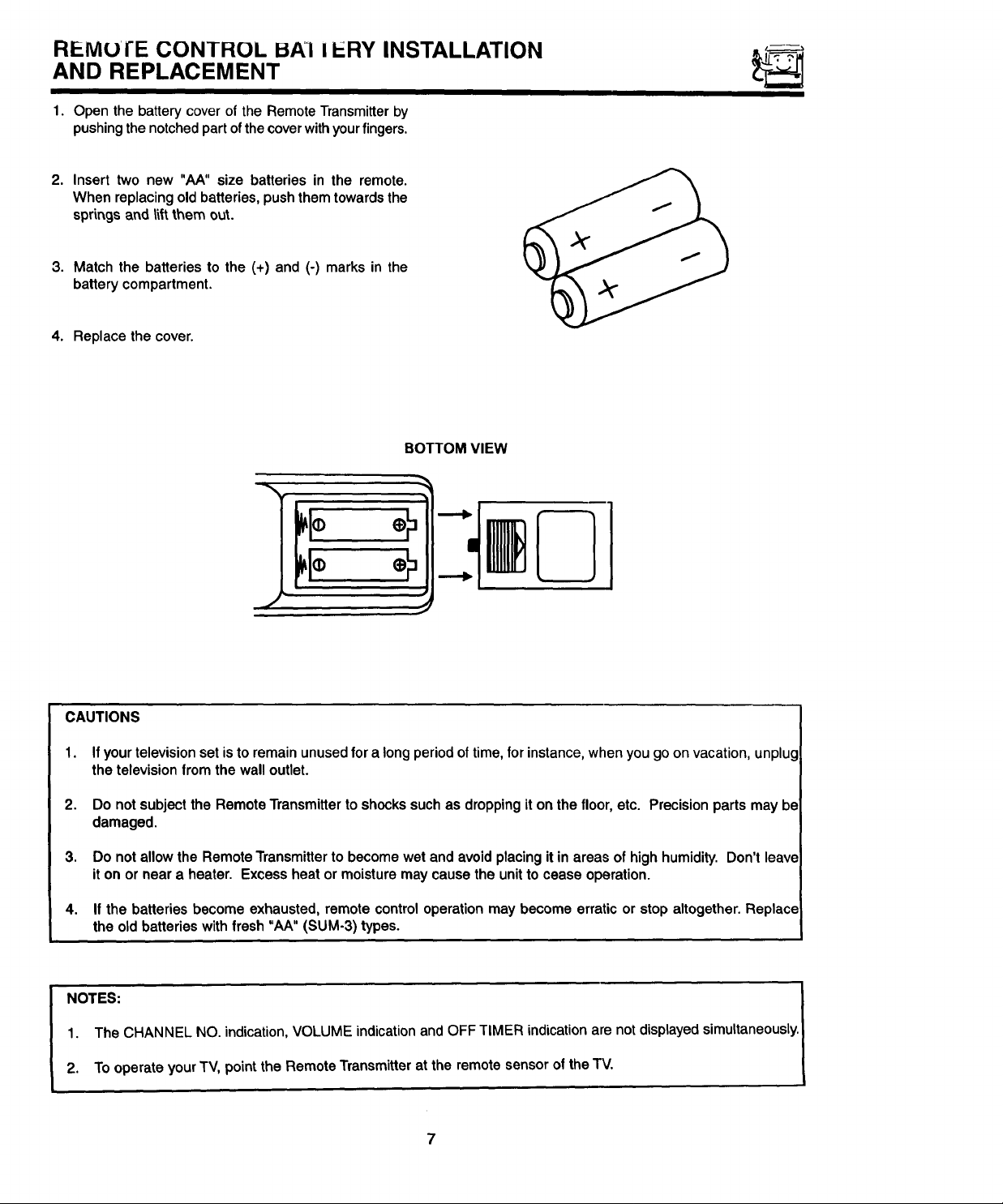
REMUI'E CONTROL I ERY INSTALLATION
AND REPLACEMENT
1. Open the battery cover of the Remote Transmitter by
pushing the notched part ofthe cover with your fingers.
2. Insert two new "AA" size batteries in the remote.
When replacing old batteries, push them towards the
sprir_gsand ti_tthem out.
3. Match the batteries to the (+) and (-) marks in the
battery compartment.
4. Replace the cover.
BOTTOM VIEW
lIl:
CAUTIONS
1. Ifyour television set is to remain unused for a long period of time, for instance, when you go on vacation, unplug
the television from the wall outlet.
2. Do not subject the Remote Transmitter to shocks such as dropping it on the floor, etc. Precision parts may be
damaged.
3. Do notallowthe RemoteTransmitterto become wet andavoidplacingit in areas of high humidity.Don't leave
iton or neara heater. Excessheator moisturemaycausethe unitto ceaseoperation.
4. If the batteries become exhausted, remote control operation may become erratic or stop altogether. Replace
the old batteries with fresh "AA" (SUM-3) types.
1. The CHANNEL NO. indication, VOLUME indication and OFF TIMER indication are not displayed simultaneously.
NOTES: I
2. To operate your TV, point the Remote Transmitter at the remote sensor of the TV.
Page 8
HUW TO SET UP YOUR NEW HITACHI COLOR TV
ANTENNA
Unless your TV is connected to a cable TV system or to a centralized antenna system, a good outdoor colorTV anten-
na is recommended for best performance. However, if you are located in an exceptionally good signal area that is free
from interference and multiple image ghosts, an indoor antenna may be sufficient.
LOCATION
Select an area where sunlight or bright indoor illumination will not fall directly on the picture screen. Also, be sure that
the location selected allows a free flow of air to and from the back cover of the set.
To avoid cabinet warping, cabinet color changes, and increased chance of set failure, do not place the TV where tem-
peratures can become excessively hot. For example, in direct sunlight or near a heating appliance, etc.
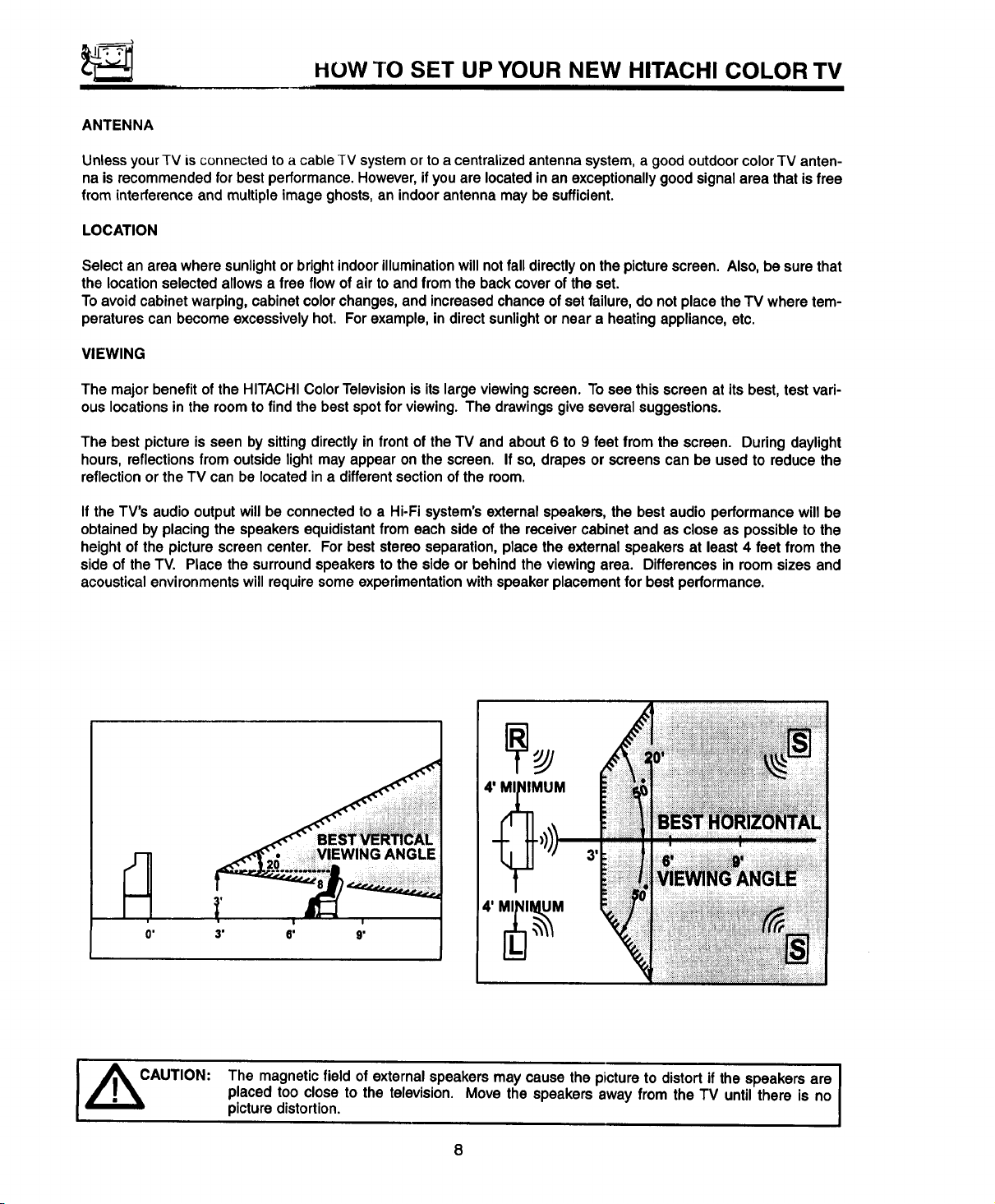
VIEWING
The major benefit of the HITACHIColorTelevisionis its largeviewingscreen.Tosee thisscreenat itsbest, test vari-
ouslocationsinthe roomtofind thebestspotfor viewing.The drawingsgiveseveralsuggestions.
The best picture is seen by sitting directly in front of the TV and about 6 to 9 feet from the screen. During daylight
hours, reflections from outside light may appear on the screen. If so, drapes or screens can be used to reduce the
reflection or the TV can be located in a different section of the room.
If the TV's audio output will be connected to a Hi-Fi system's external speakers, the best audio performance will be
obtained by placing the speakers equidistant from each side of the receiver cabinet and as close as possible to the
height of the picture screen center. For best stereo separation, place the external speakers at least 4 feet from the
side of the TV. Place the surround speakers to the side or behind the viewing area. Differences in room sizes and
acoustical environments will require some experimentation with speaker placement for best performance.
I ,_CAUTION:
_IMUM
,
3' 6' 9'
The magnetic field of external speakers may cause the picture to distort if the speakers are I
placed too close to the television. Move the speakers away from the TV until there is no
picture distortion.
4' MI_NII_UM
8
I
Page 9
HOW TO SET UP YOUR NEW HITACHI COLOR TV
I
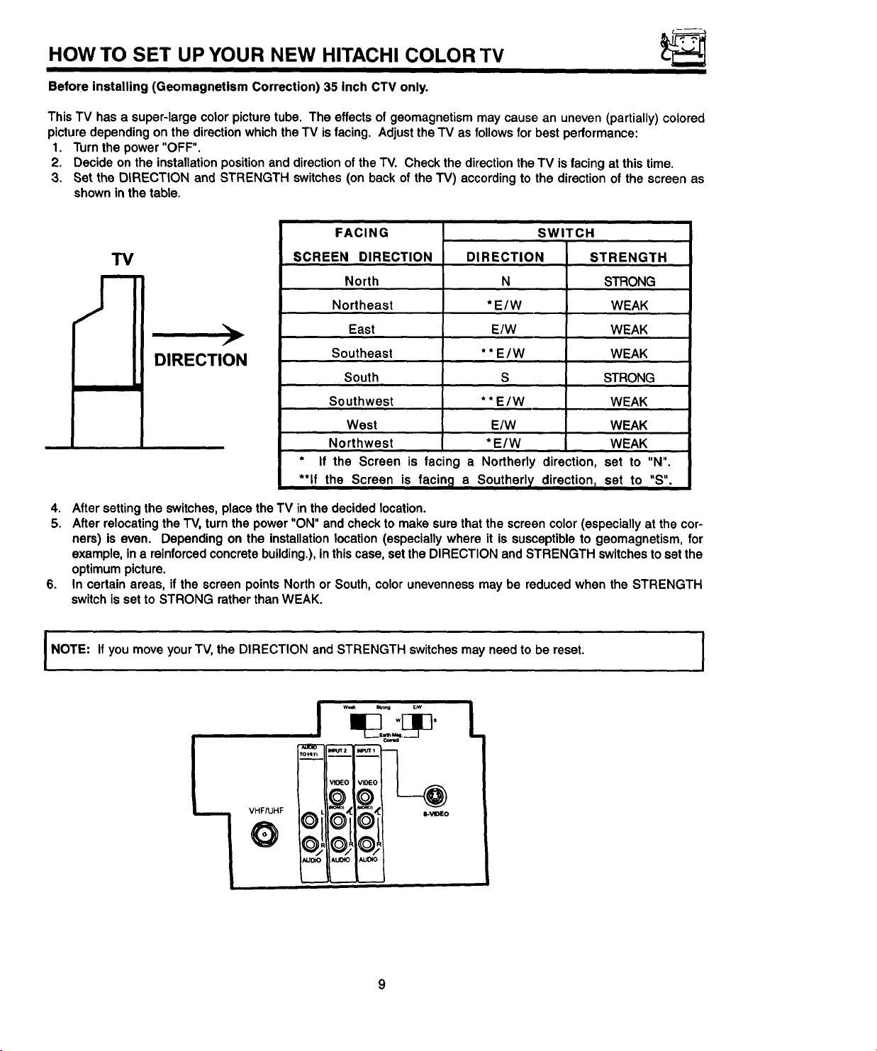
Before installing (Geomagnetism Correction) 35 inch CTV only.
ThisTV hasa super-largecolorpicturetube. The effectsof geomagnetismmay causean uneven(partially)colored
picturedependingonthe directionwhichtheTV isfacing. AdjusttheTV as followsfor best performance:
1. Turnthepower"OFF".
2. Decideon theinstallationpositionanddirectionoftheTV. Checkthe directiontheTV isfacingatthis time.
3. Set the DIRECTION and STRENGTH switches(on back ofthe TV) accordingto the direction of thescreen as
showninthe table.
i
TV
DIRECTION
>
FACING
SCREEN DIRECTION
North
Northeast
East
Southeast
South
Southwest
West
Northwest
* If the Screen is facing a
**If the
Screen is facing a Southerly directionr set to "S",
DI RECTION STR ENGTH
* E/W WEAK
E/W WEAK
* * E/W WEAK
* * E/W WEAK
E/W WEAK
*E/W WEAK
Northerly direction, set to "N".
SWITCH
N STRONG
S STRONG
4. Aftersettingthe switches, placetheTV inthe decidedlocation.
5. AfterrelocatingtheTV,turnthepower"ON" andcheckto makesurethatthe screencolor(especiallyat the cor-
ners) is even. Dependingon the installationlocation(especiallywhereit is susceptibleto geomagnetism,for
example,ina reinforcedconcretebuilding.),inthiscase,settheDIRECTIONand STRENGTHswitchestosetthe
optimumpicture.
6. In certainareas, if the screenpointsNorthor South,colorunevennessmay be reducedwhen the STRENGTH
switchissetto STRONG ratherthanWEAK.
NOTE: IfyoumoveyourTV,the DIRECTION andSTRENGTH switchesmay needto be reset. I
.
I
V_EO I VIDEO
I
VHF/UHF
O
O"
/gJ040
011©1
iAUOIO I AUDIO
i
Page 10
I
HOOKUP CABLES AND CONNECTORS
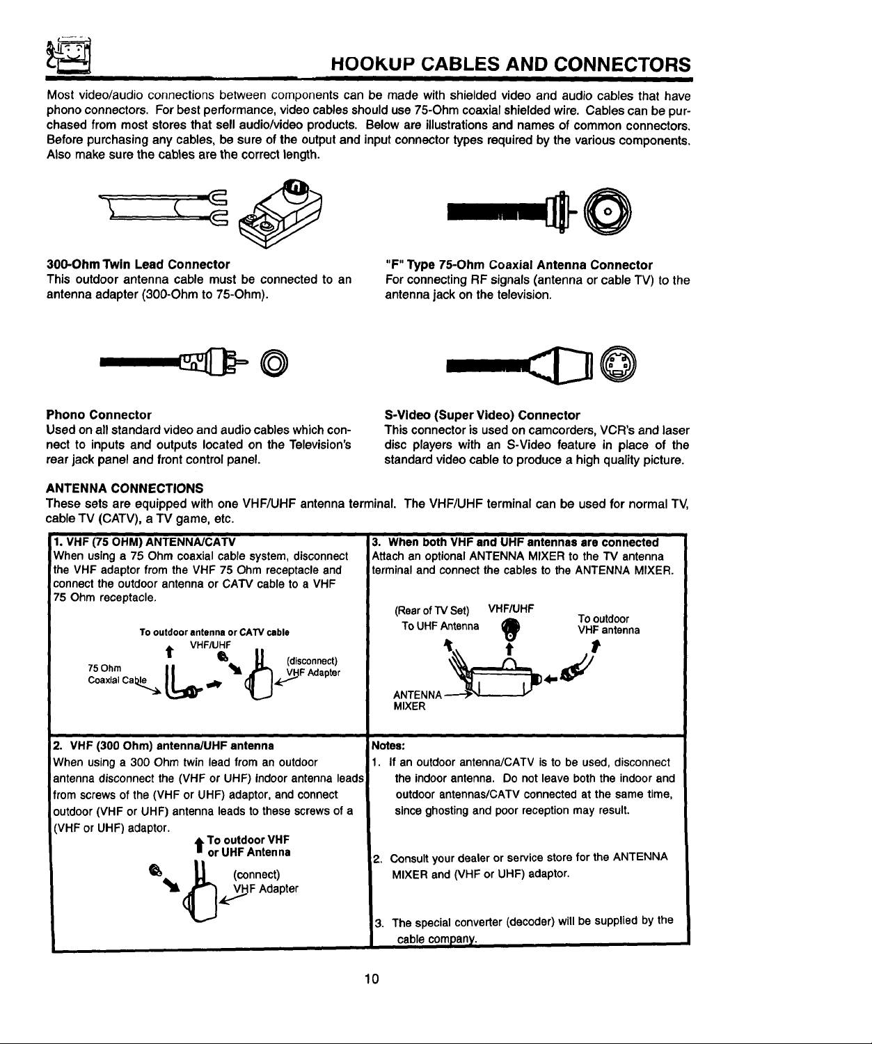
Most video/audio connections between components can be made with shielded video and audio cables that have
phono connectors. For best performance, video cables should use 75-Ohm coaxial shielded wire. Cables can be pur-
chased from most stores that sell audio/video products. Below are illustrations and names of common connectors.
Before purchasing any cables, be sure of the output and input connector types required by the various components.
Also make sure the cabtes are the correct length.
300-OhmTwin Lead Connector
This outdoorantenna cable must be connectedto an
antennaadapter (300-Ohmto 75-Ohm).
"F" Type 75-Ohm Coaxial Antenna Connector
For connecting RF signals (antenna or cable TV) to the
antenna jack on the television.
@
Phono Connector
Used on all standard video and audio cables whichcon-
nect to inputs and outputs located on the Television's
rear jack panel and front control panel.
ANTENNA CONNECTIONS
These sets are equipped with one VHF/UHF antenna terminal. The VHF/UHF terminal can be used for normal TV,
cable TV (CATV), a TV game, etc.
_. VHF (75 OHM) ANTENNA/CATV
When using a 75 Ohm coaxial cable system, disconnect
the VHF adaptor from the VHF 75 Ohm receptacle and
connect the outdoor antenna or CATV cable to a VHF
75 Ohm receptacle.
To outdoor antenna or CATV cable
VHF/UHF
7sOh,. I I _. _L (disconnect)
C°axlal CabJ-_ L_I_ P
t _ _ (_,_._y._FAdapter
S-Video (SuperVideo) Connector
Thisconnectoris usedoncamcorders,VCR's andlaser
disc players with an S-Video feature in place of the
standardvideocableto producea highqualitypicture.
3. When both VHF and UHF antennas are connected
Attach an optional ANTENNA MIXER to the TV antenna
terminal and connect the cables to the ANTENNA MIXER.
(RearofI"VSet) VHF/UHF
ToUHFAntenna VHF antenna
t_) To outdoor
t t
ANTENNA_ '{"_'J_ _='_//
MIXER
i
2. VHF (300 Ohm) antenna/UHF antenna
When usinga 300 Ohm twin lead from an outdoor
antenna disconnectthe (VHF or UHF) indoorantenna leads
from screwsof the (VHF or UHF) adaptor, and connect
outdoor(VHF or UHF) antenna leads to these screwsof a
VHF or UHF) adaptor.
_'_,,. U (connect)
t To outdoor VHF
or UHF Antenna
(_,_F Adapter
Notes:
1. If an outdoor antenna/CATV is to be used, disconnect
the indoorantenna. Do not leave both the indoorand
outdoorantennas/CATV connectedat the same time,
sinceghostingand poor receptionmay result.
2. Consult your dealer or service store for the ANTENNA
MIXER and (VHF or UHF) adaptor.
3. The specialconverter(decoder) willbe suppliedby the
cablecompany.
10
Page 11
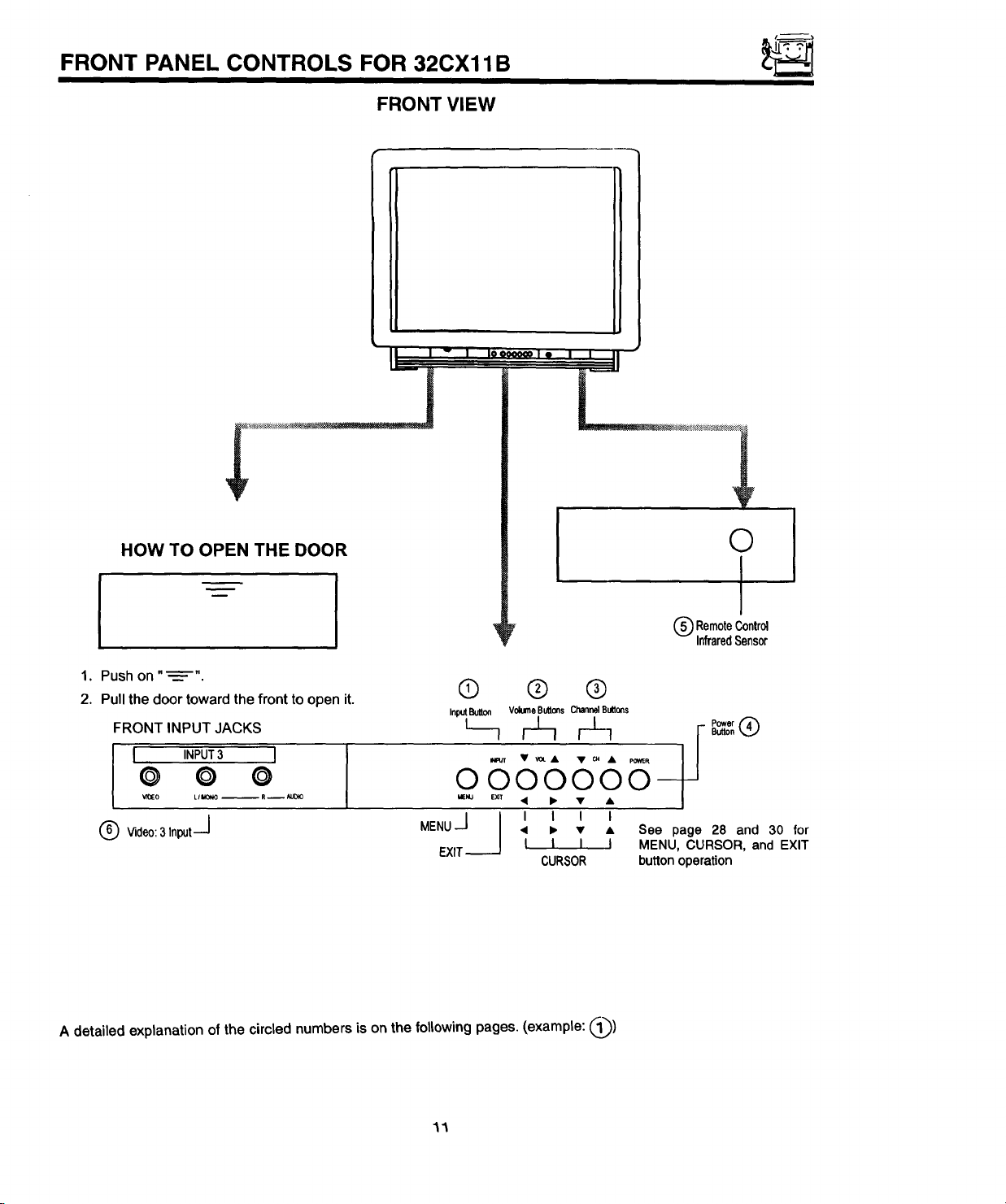
FRONT PANEL CONTROLS FOR 32CX11B
FRONT VIEW
I I _ l looooo_o I • I I II
I o' .... II
HOW TO OPEN THE DOOR
1. Push on "_"
2. Pull the door toward the front to open it.
FRONT INPUT JACKS
I INPUT3 I
© 0 ©
Vl0EO LII_ONO -- R -- _UOIO
J
©
I
'_ V @ RemoteControl
' InfraredSensor
® @ @
InputButton VolumeButtes Channel Buttons
O00O 0
MENU • I_ • • See page 28 and 30 for
J I I I I I
EXIT-_ I I I I MENU, CURSOR, and EXIT
CURSOR buttonoperation
Powsr
Button
A detailed explanation of the circled numbers is on the following pages. (example: @)
11
Page 12
I
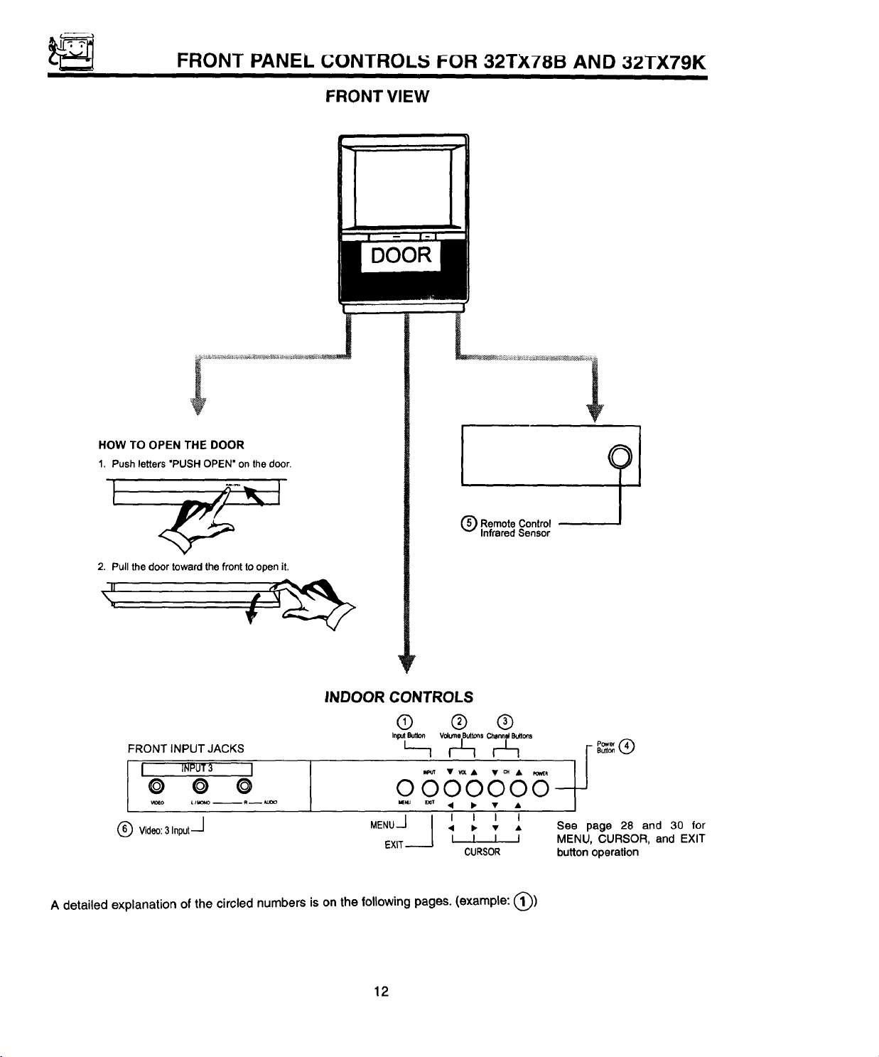
FRONT PANEL GONTROL,'5 I=OR 32TX78B AND 32TX79K
FRONT VIEW
DOOR
HOW TO OPEN THE DOOR
1. Push letters "PUSH OPEN' on the door.
Q RemoteControl
InfraredSensor
2. Pull the door toward the front to open it.
INDOOR CONTROLS
© ® ®
FRONT INPUT JACKS
I INPUT3 I
© O ©
Vl0EO tl_ -- _-- _u_o
(_) Video:3Input--j
A detailed explanation of the circled numbers is on the following pages. (example: (_))
I
MENU • D, • • See page 28 and 30 for
J I I I I I
EXIT-----J I I I I MENU, CURSOR, and EXIT
CURSOR button operation
12
Page 13
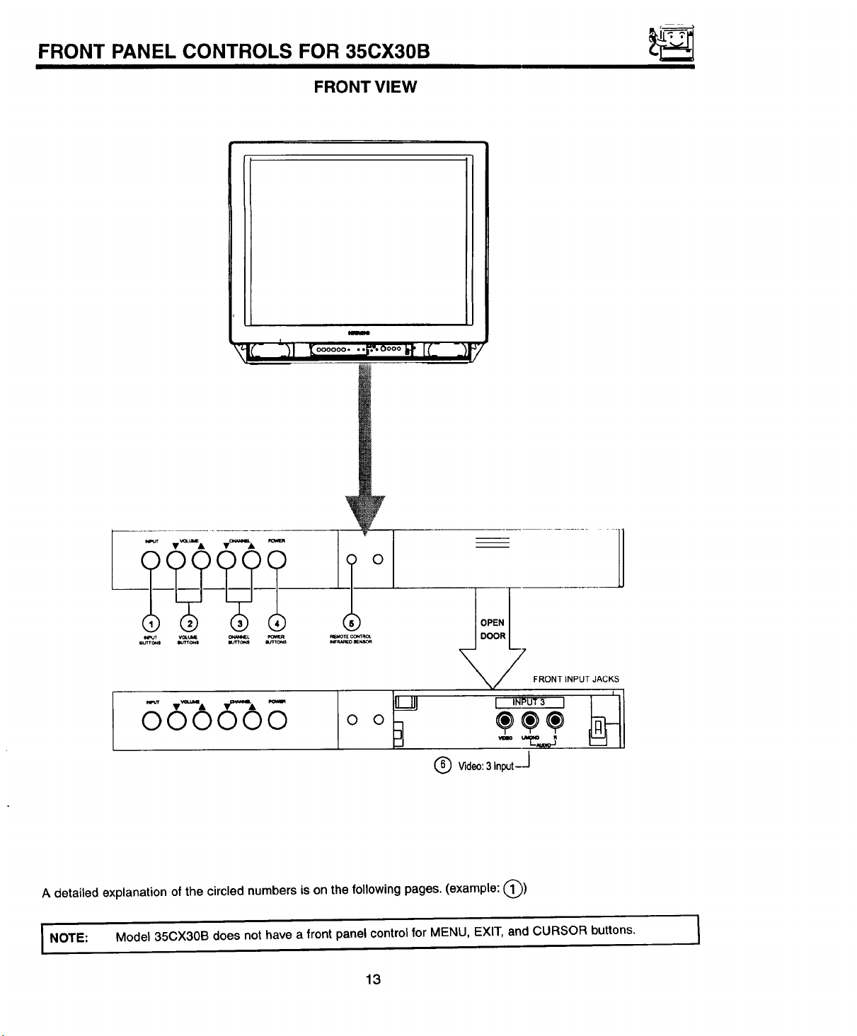
FRONT PANEL CONTROLS FOR 35CX30B
FRONT VIEW
I
\!;- t__l_=ooo......oooo_.It- -_
....i
-j
N=UT V_.Ul_ CV_N_L
000000 o o
A detailed explanation of the circled numbers is on the following pages. (example: @)
I NOTE: Model 35CX30B does not have a front panel control for MENU, EXIT, and CURSOR buttons.
_T_ _
L_)_INPUT3 I _1
® wdoo:31._t--I
13
I
Page 14
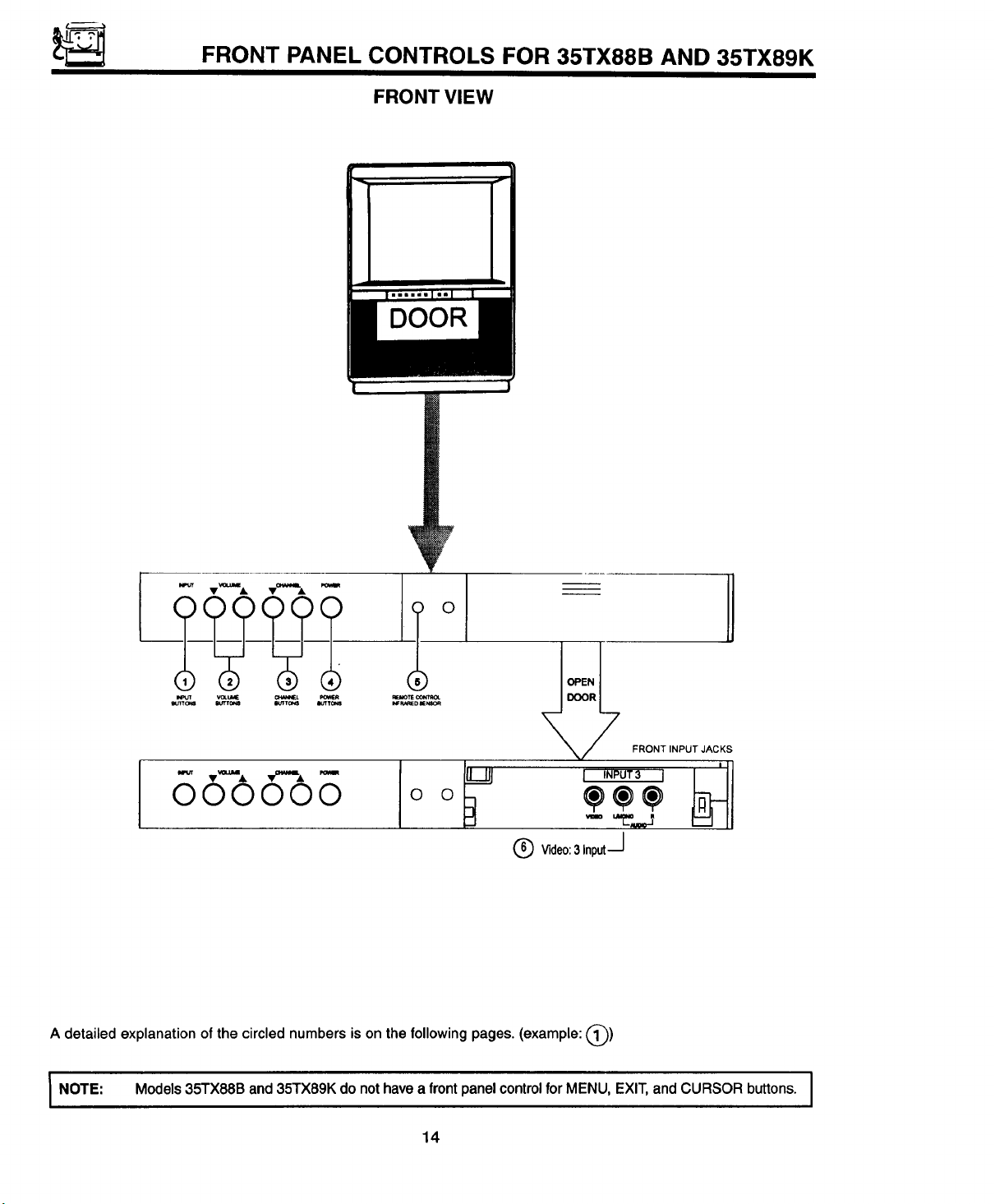
FRONT PANEL CONTROLS FOR 35TX88B AND 35TX89K
FRONT VIEW
DOOR
A detailed explanation of the circled numbers is on the following pages. (example: (_))
I NOTE" Models 35TX88B and 35TX89K do not have a front panel control for MENU, EXIT, and CURSOR buttons. I
14
Page 15
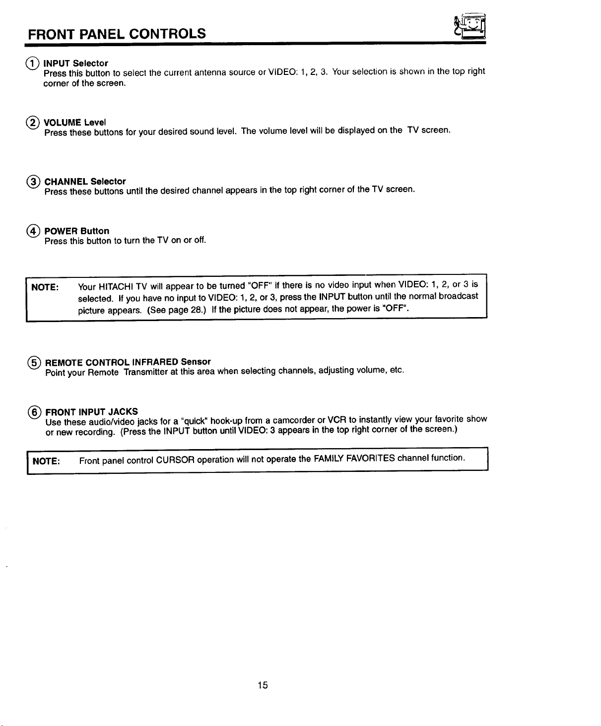
FRONT PANEL CONTROLS
INPUT Selector
Press this button to select the current antenna source or VIDEO: 1, 2, 3. Your selection is shown in the top right
corner of the screen.
(_) VOLUME Level
Press these buttons for your desired sound level. The volume level will be displayed on the TV screen.
(_ CHANNEL Selector
Pressthese buttons untilthe desired channelappearsinthetoprightcornerof theTV screen.
(_) POWER Button
Pressthisbutton to turntheTV on oroff.
NOTE: Your HITACHI TV will appear to be turned "OFF" if there is no video input when VIDEO: 1, 2, or 3 is
selected. If you have no input to VIDEO: 1, 2, or 3, press the INPUT button until the normal broadcast
picture appears. (See page 28.) If the picture does not appear, the power is "OFF".
(_ REMOTE CONTROL INFRARED Sensor
Pointyour Remote Transmitter at this area when selecting channels, adjusting volume, etc.
(_) FRONT INPUT JACKS
Usethese audio/videojacksfora "quick" hook-upfroma camcorderor VCRtoinstantlyviewyourfavoriteshow
or new recording,(Pressthe INPUT buttonuntilVIDEO: 3 appearsinthe toprightcornerof the screen.)
I NOTE: Front panel control CURSOR operation will not operate the FAMILY FAVORITES channel function. I
15
Page 16
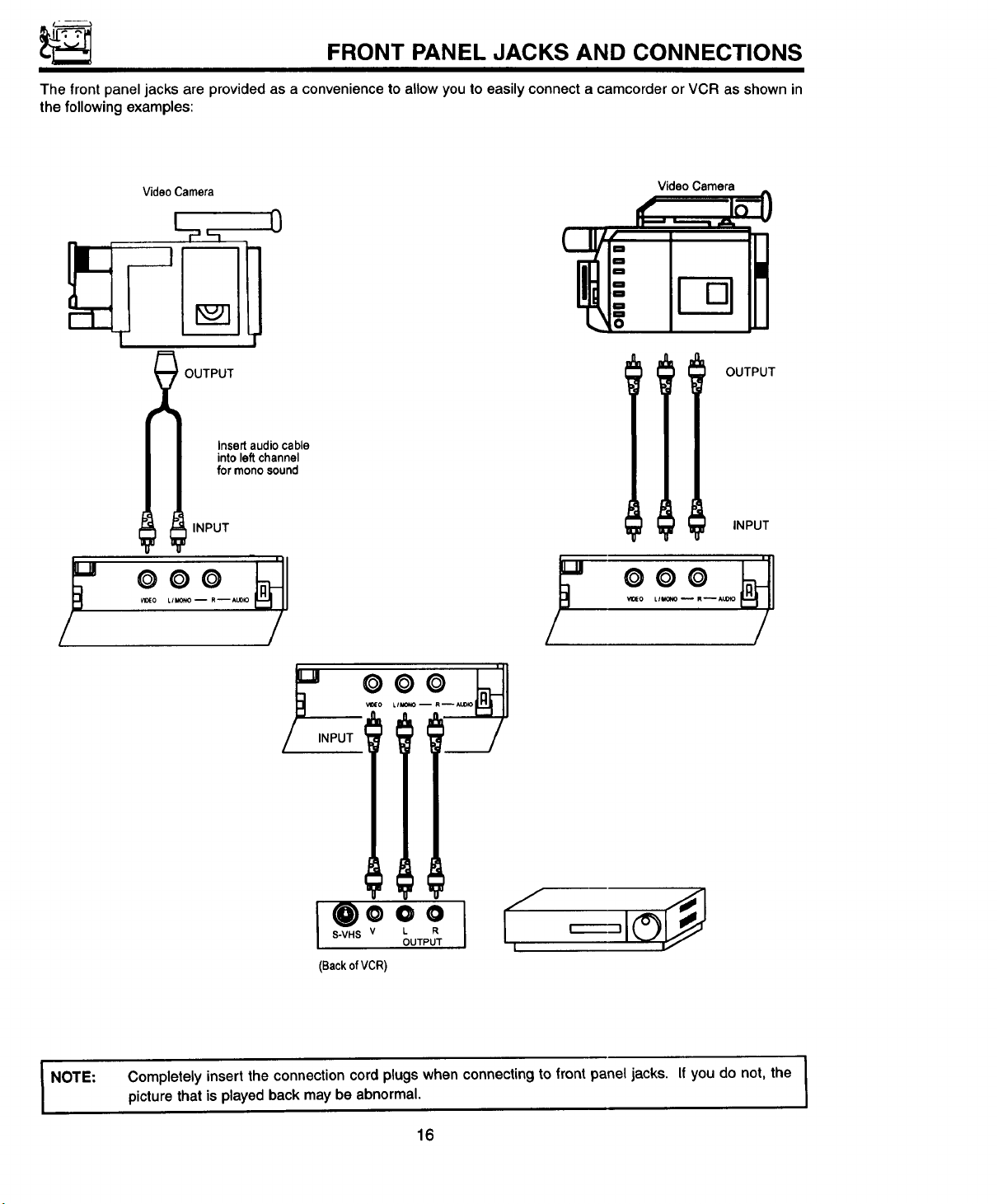
FRONT PANEL JACKS AND CONNECTIONS
The front panel jacks are provided as a convenience to allow you to easily connect a camcorder or VCR as shown in
the following examples:
Video Camera
_ OUTPUT
INPUT INPUT
Insert audio cable
into left channel
for mono sound
Video Camera
OUTPUT
000 0
wo_o L/l_o_o 1 RIAL_ Vt0EO AU0tO
/ / /
NOTE:
_o
NPUT
(BackofVCR)
Completely insert the connection cord plugs when connecting to front panel jacks. If you do not, the
picture that is played back may be abnormal.
16
I
I
Page 17
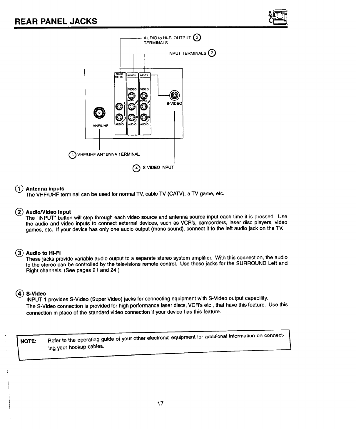
REAR PANEL JACKS
-- AUDIO to HI-FI OUTPUT _3)
AIJ_O INPUT;t IN_T I
rOHIR
TERMINALS
INPUT TERMINALS Q
VIDEO _O_O
@©
S-VIDEO
VHF/UHF s_,uo_o AUOIO AUDIO
I
Q VHF/UHF ANTENNA TERMINAL
(_ S-VIDEO INPUT
(_ Antenna Inputs
The VHF/UHF terminal can be used for normal TV, cable TV (CATV), a TV game, etc.
(_ AudioNideo Input
The "INPUT" buttonwillstepthrough each videosourceand antennasourceinputeach time it is pressed. Use
the audio and video inputsto connectexternaldevices,suchas VCR's, camcorders,laserdiscplayers,video
games,etc. If your devicehasonlyone audiooutput(monosound),connectitto theleftaudiojack on theTV.
Audio to HI-Fi
These jacks provide variable audio output to a separate stereo system amplifier. With this connection, the audio
to the stereo can be controlled by the televisions remote control. Use these jacks for the SURROUND Left and
Right channels. (See pages 21 and 24.)
(_ S-Video
INPUT 1 provides S-Video (Super Video) jacks for connecting equipment with S-Video output capability.
The S-Video connection is provided for high performance laser discs,VCR's etc., that have this feature. Use this
connection in place of the standard video connection if your device has this feature.
the operating guide of your other etectronic equipment for additional information on connect-
to
Refer
NOTE:
ing your hookup cabtes.
/
_1
17
Page 18
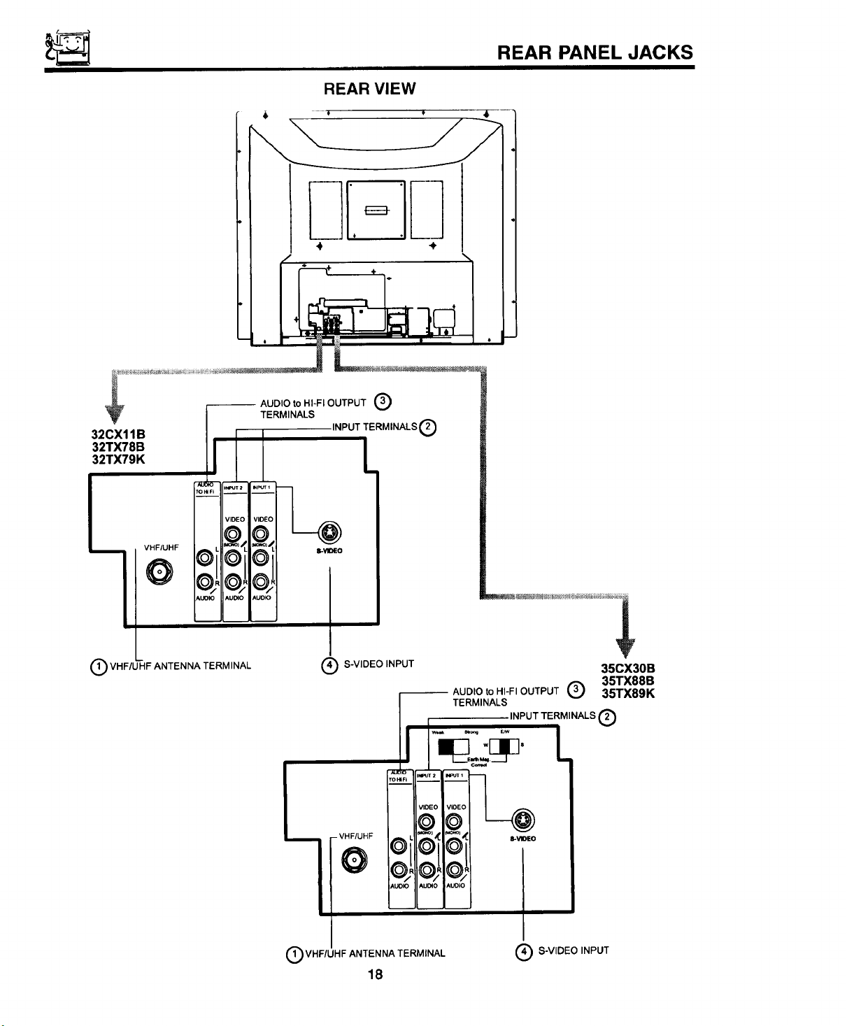
32CX11B
32TX78B
32TX79K
REAR VIEW
AUDIO to HI-FI OUTPUT Q
TERMINALS
INPUT TERMINALS O
REAR PANEL JACKS
O VHF/U'HF ANTENNA TERM INAL
(_ S-VIDEO INPUT
I
VHF/UHF ANTENNA TERMINAL
18
AUDIO to HI-FI OUTPUT _ 35TX89K
TERMINALS
w_ _o_ EJw
INPUT TERMINALS _'_
(_ S-VIDEO INPUT
35CX30B
35TX88B
Page 19
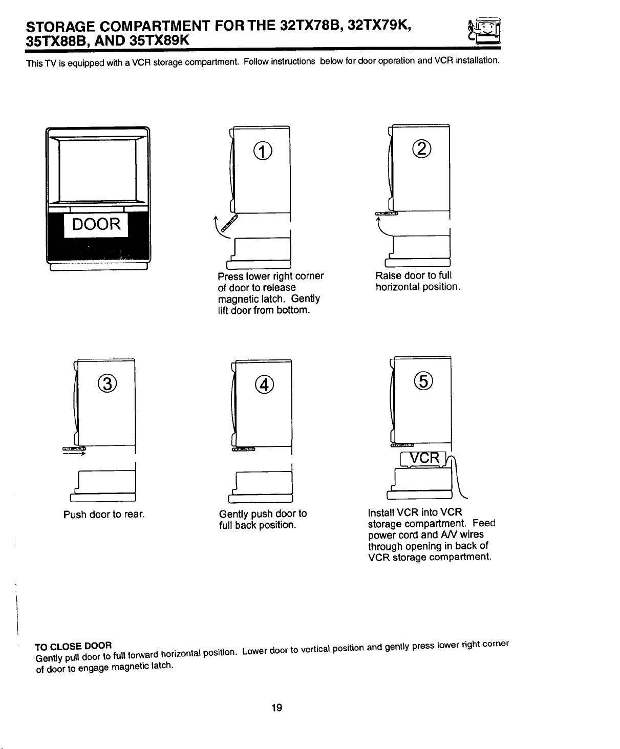
STORAGE COMPARTMENT FOR THE 32TX78B, 32TX79K,
35TX88B, AND 35TX89K
ThisTV is equipped with a VCR storage compartment. Followinstructions below for door operation and VCR installation.
®
! i!
DOOR
®
I !
Push door to rear.
Press lower right corner
of door to release
magnetic latch. Gently
lift door from bottom.
®
Gently push door to
full back position.
\
I
Raise door to full
horizontal position.
®
Install VCR into VCR
storage compartment. Feed
power cord and AN wires
through opening in back of
VCR storage compartment.
TO CLOSE DOOR
Gently pull door to full forward horizontal position. Lower door to vertical position and gently press lower right corner
of door to engage magnetic latch.
19
Page 20
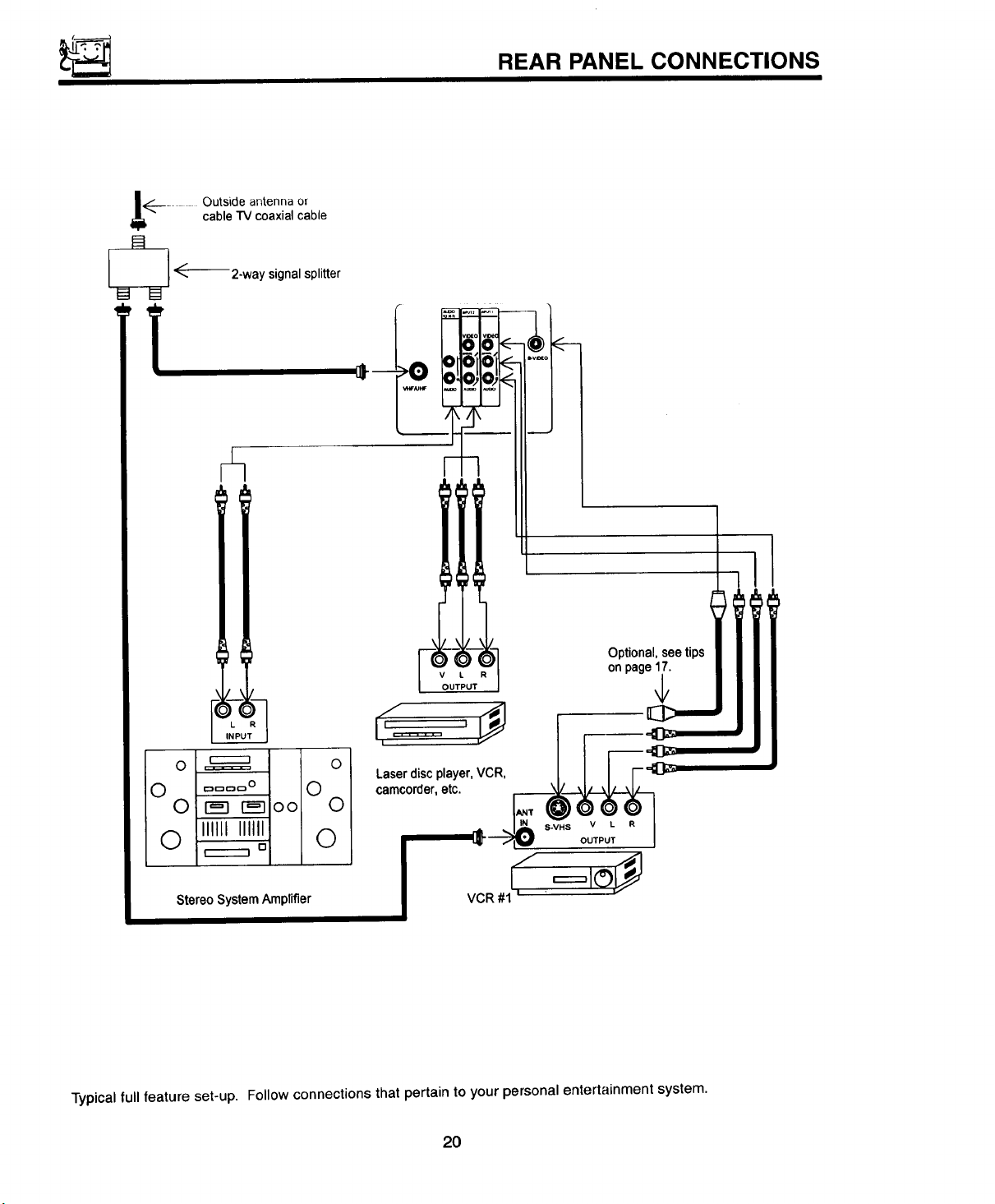
REAR PANEL CONNECTIONS
!_.__ ...... Outside antenna or
_ _------ 2-way signal splitter
cable TV coaxial cable
V L R
OUTPUT
Optional,seetips
onpage17.
Laserdiscplayer,VCR,
camcorder,etc.
$-VHS V L R
OUTPUT
Stereo System Amplifier
Typical full feature set-up. Follow connections that pertain to your personal entertainment system.
20
Page 21

EXTERNAL CONNECTIONS
CONNECTING EXTERNAL AUDIO AMPLIFIER
To control the audio level of an external audio amplifier with the Remote Transmitter, connect the system as shown
below in Fig. 1.
I NOTE:
(REAROFTV SET) AUDIO
u
AUDIOTO HI-FITERMINAL ITOHI-FI
TO AUDIO INPUT TERMINA._(
OF EXTERNAL AMPLIFIER
w
EXTERNAL
SPEAKERS
| ....... I
AUDIO AMPLIFIER
EXTERNAL
SPEAKERS
To prevent damage to the speaker and distorted sound, set the volume control of the audio amplifier
lower and adjust the sound using the Remote Transmitter of the TV set.
21
Page 22

CONNECTING EXTERNAL VIDEO SOURCES
The exact arrangement you use to connect the Video Cassette Recorder, Video Disc Player and Video Camera to your
TV set is dependent on the model and features of each component. Check the Owner's Manual of each component
for the location of its video and audio inputs and outputs. The following connection diagrams are offered as sugges-
tions. However, you may need to modify them to accommodate your particular assortment of components and fea-
tures. For best performance, video and audio cables should be made from coaxial shielded wire.
Before Operating External Video Source
The input mode is changed every time the INPUT button is pressed as shown below. Connect external source to the
INPUT terminal, then press the INPUT button as necessary to view the input source. (See page 28.)
INPUT MODE SELECTION ORDER
{Antenna) !lnput)
121 _I VIDEO
NOTE: When the TV is set to "VIDEO" and a video signal is not received from VIDEO INPUT JACK on the jack
panel of the TV (i.e., VCRNideo Disc Player, etc. is not connected or the video device is OFF), the
screen will be grey-blue.
CONNECTING MONAURAL AUDIO VCR OR VIDEO DISC PLAYER
1. Connect the cable from the VIDEO OUT of the VCR or the Video Disc Player to the INPUT (VIDEO) jack on the TV
set. (Fig. 1)
2. Connect the cable from the AUDIO OUT of the VCR or the Video Disc Player to the INPUT (MONO)/L(AUDIO) jack.
3. Press the INPUT button to view the program from the VCR or Video Disc Player. The mode "VIDEO" disappears
automatically after approximately 8 seconds.
4. Press the INPUT button to return to the previous channel.
5. See below.
Video Cassette Recorder
f ",,,,
TV INPUT
'ERMINAL
INPUT
VIDEO
MQNO)
VIDEO OUT AUDIO OUT
II I I
AU DIO
FIG. 1
22
Page 23

CONNECTING EXTERNAL VIDEO SOURCES
I II
CONNECTING STEREO VCR OR STEREO VIDEO DISC PLAYER
1. Connect the cable from the VIDEO OUT of the VCR or the Video Disc Player to the "INPUT (VIDEO)" jack on the
TV set. (Fig. 1)
2. Connect the cable from the AUDIO OUT "R" of the VCR or the Video Disc Player to the "INPUT(AUDIO/R)" jack.
3. Connectthe cablefrom theAUDIO OUT "L" oftheVCR orthe VideoDiscPlayer to the "INPUT(AUDIO/L)"jack.
4. Press the INPUT buttontoview the programfrom theVCR orVideo DiscPlayer.The mode "VIDEO" disappears
automaticallyafterapproximately8 seconds.
5. Press the INPUT button to return to the previous channel.
Video Cassette Recorder
J' : '.,='" -'L
TV INPUT
TERMINAL
INPU..._I
VIDEO
rMONO_
% , , /
VIDEO OUT AUDIO OUT
NOTE:
AUDIO
FIG. 1
•rv INPUT
tti,
8-VH8 V L R
@ ®®
OUTPUT
BACK OF VCR
HITACHI MODEL VT-S7G1A
or dmlw modal
TERMINAL
Completely insertthe connectioncordplugswhenconnectingto REARpanel jacks. If you do not the
picturethatis playedbackwillbe abnormal.
If you have an S-VHS VCR, use the S-INPUT cable in place ofthe standard video cable.
A s_,ngteVCP, can be used forVCR #1 and VCR #2, but note that a VCR cannot record its own video or
line output. (INPUT: 1 in example on page 20.) Refer to your VCR operating guide for more information
on "line" input-output connections.
23
Page 24

AUDIO SYSTEM SET-UP
Match the numbers below to the diagram lor speaker placement and refer to the table for the different surround sound
requirements. (See page 54 for SURROUND functions.)
(_) The television's internal speakers.
(_ These speakers are connected to a separate audio amplifier. Use the "Audio to Hi-Fi" output on the TV.
LR
OUT IN
STEREO SYSTEM I
AMPLIFIER
SURROUND
FEATURE
OFF
SIMULATE
MUSIC
MOVIE
REQUIRED
CONNECTION
(b
(D
OPTIONAL
CONNECTION
Q
(b
EFFECT
Receive mono and stereo sound.
At mono input, sound will be louder.
At stereo input, sound of music will be louder.
Surround channel added to left and right audio
amplifier speakers.
Movie theater reproduction, surround channel
added to left and right audio amplifier speakers.
24
Page 25

THE REMOTE CONTROL (CLU-418U)
In addition to controlling all the functions on your HITACHI Color TV, the new remote is designed to operate different
types of VCR's, CATV (Cable TV), and satellite converters with one touch. Basic operation keys are grouped togeth-
er in one area.
To operateyourTV, point the remote at the remotesensorof theTV and press theTV button on the remote. The
remotewillnow controlyourTV.
To operate your VCR, point the remote at the remote sensor of the VCR and press the VCR button. The remote will
now control your VCR. (See page 34 for instructions on how to program the remote to control your VCR.)
To operateyourcable/satellitebox,point the remoteat the remotesensorof the cable/satelliteboxand pressthe
CABLEbutton.The remotewillnowcontrolyourcable/satellitebox. (See page36 forinstructionsonhowto program
the remoteto controlyourcable/satellitebox.)
"
®
HELP THEATER TV/VCR
®
®
HOME
®
@
Thesebuttonsallowthe remoteto controlyourTV,
VCR, or cable/sateUitebox dependingon which
modeischosen,as explainedabove.
TV/VCR Button
®
Whenthe remoteis intheTV orVCR mode,thisis
the TVNCR button. When the remote is in the
CABLE/SATELLITEmode,thisIsthe A/Bbutton.
VOL CH
03(!3(i)
(X) (D
(X) (X) (D
INPUT SLEEP
OCDO
HITACHI
CLU-418U
(_ PRECODEDVCR Buttons
Thesebuttonsalwaystransmitthe chosenprecod-
edVCR codes.
HELP Button
®
Hitachi'snew remotecontrolsnow have a HELP
button.Simplypressthisbuttonifhelpisneededto
changemenusettings,andour new contextsensi-
tive Help systemwillprovideexplanationsand/or
directionsfor whateverfunction yourcursorisonat
thattime.
HOME THEATER Button
This button allows direct access to the SUR-
ROUND functions.
J
25
Page 26
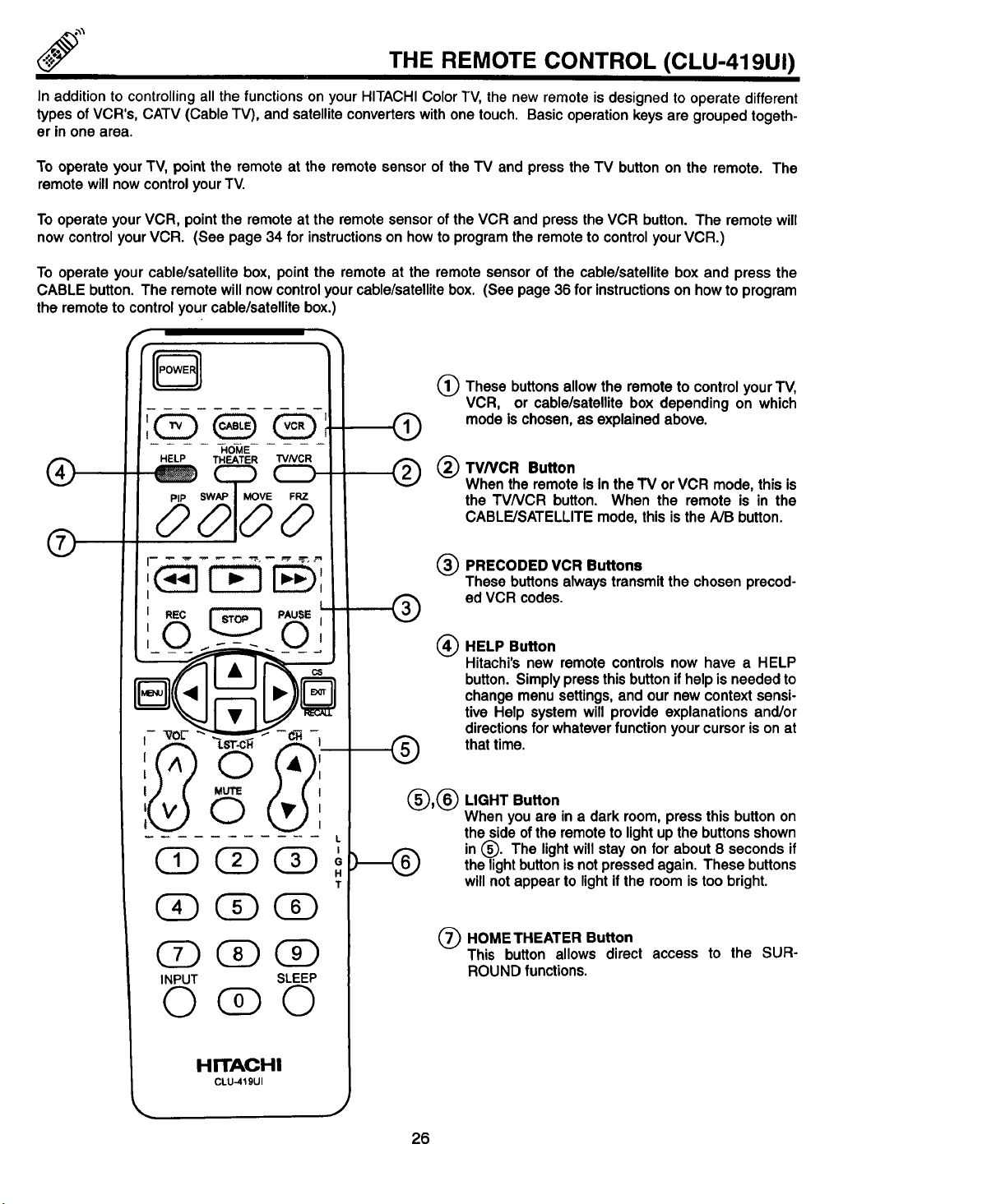
THE REMOTE CONTROL (CLU-419UI)
In addition to controlling all the functions on your HITACHI Color TV, the new remote is designed to operate different
types of VCR's, CATV (Cable TV), and satellite converters with one touch. Basic operation keys are grouped togeth-
er in one area.
To operate yourTV, pointthe remoteat the remote sensorof the TV and press the TV buttonon the remote. The
remotewillnowcontrolyourTV.
To operateyourVCR, pointthe remote at the remotesensoroftheVCR andpressthe VCR button. The remotewill
nowcontrolyourVCR. (See page34 for instructionsonhowto programtheremotetocontrolyourVCR.)
To operate your cable/satellite box, point the remote at the remote sensor of the cable/satellite box and press the
CABLE button. The remote will now control your cable/satellite box. (See page 36 for instructionson how to program
the remote to control your cable/satellite box.)
(_ These buttons allow the remote to control your TV,
VCR, or cable/satellite box depending on which
mode is chosen, as explained above.
TV/VCR Button
®
When the remote Is In the TV or VCR mode, this is
the TVNCR button. When the remote is in the
CABLE/SATELLITE mode, this is the A/B button.
®
.... -HOME
HELP THEATER "FVNGR
®
®
®
I !
I REC I'_ PAUSE_l
C) Q
CDGD
OO( )
INPUT SLEEP
(_ PRECODED VCR Buttons
These buttons always transmit the chosen precod-
ed VCR codes.
®
HELP Button
®
Hitachi'snew remotecontrolsnow have a HELP
button.Simplypressthisbuttonifhelpisneededto
changemenusettings,andour new contextsensi-
tive Help systemwill provideexplanationsand/or
directionsfor whateverfunction yourcursorison at
®
(_(_ LIGHT Button
L
T
thattime.
When you are in a dark room, press this button on
the side of the remote to light up the buttonsshown
in (_). The light will stay on for about 8 seconds if
the light button is not pressed again. These buttons
will not appear to light ifthe room is too bright.
(_ HOME THEATER Button
This button allows direct access to the SUR-
ROUND functions.
HITACHI
CLU-419UI
26
Page 27
HOW TO USE THE REMOTE TO CONTROL YOUR TV
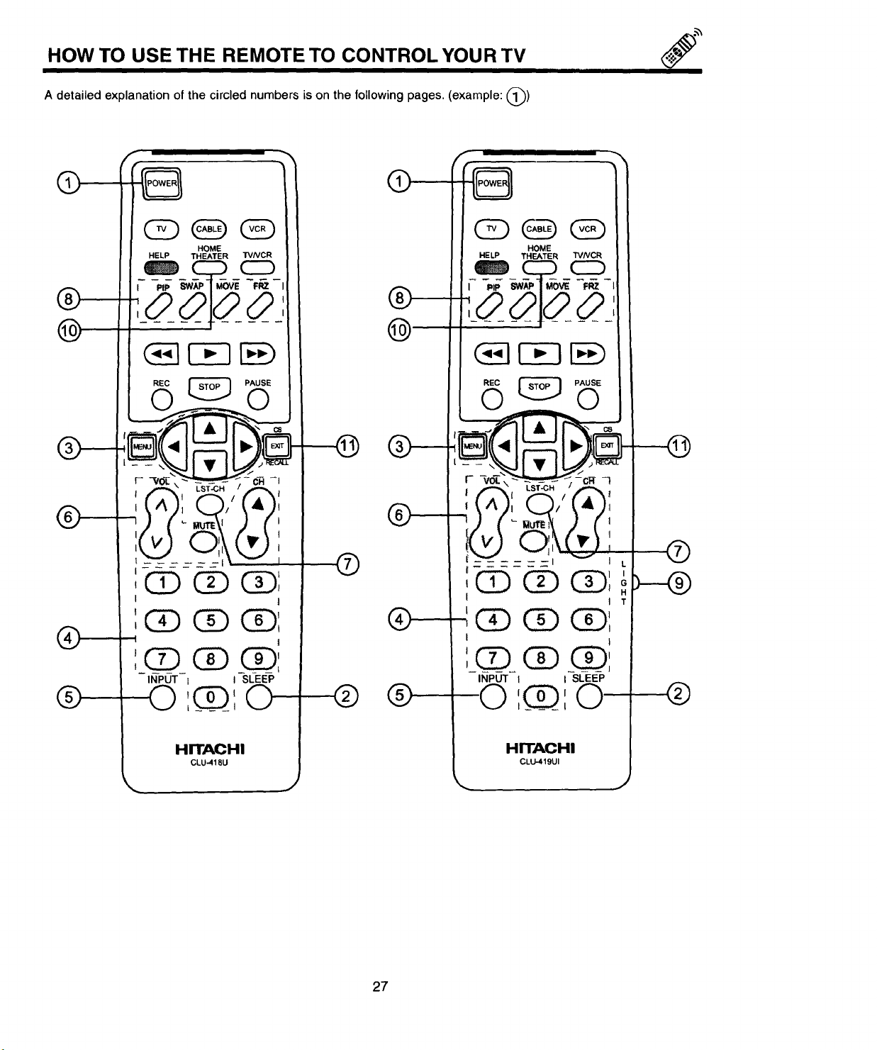
A detailed explanation of the circled numbers is on the following pages. (example: @)
HELP THEATER TVNCR
REC _ PAUSE
t
INPUT l I SLEEP
HOME
LST-CH
I
f(_),
I I
®
h8
I/Q oH
iJ_"___.©_11
®
@
-_Q
®
®
t
®
t
',(!) G) (D
!
',(2)(!)0
INPUT I I SLEEP
I0 (D (D
®
0 ',_Q_',0
T
®
HITACHI
CLU-418U
HITACHI
CLU-419UI
27
Page 28
HOW TO USE THE REMOTE TO CONTROL YOUR TV
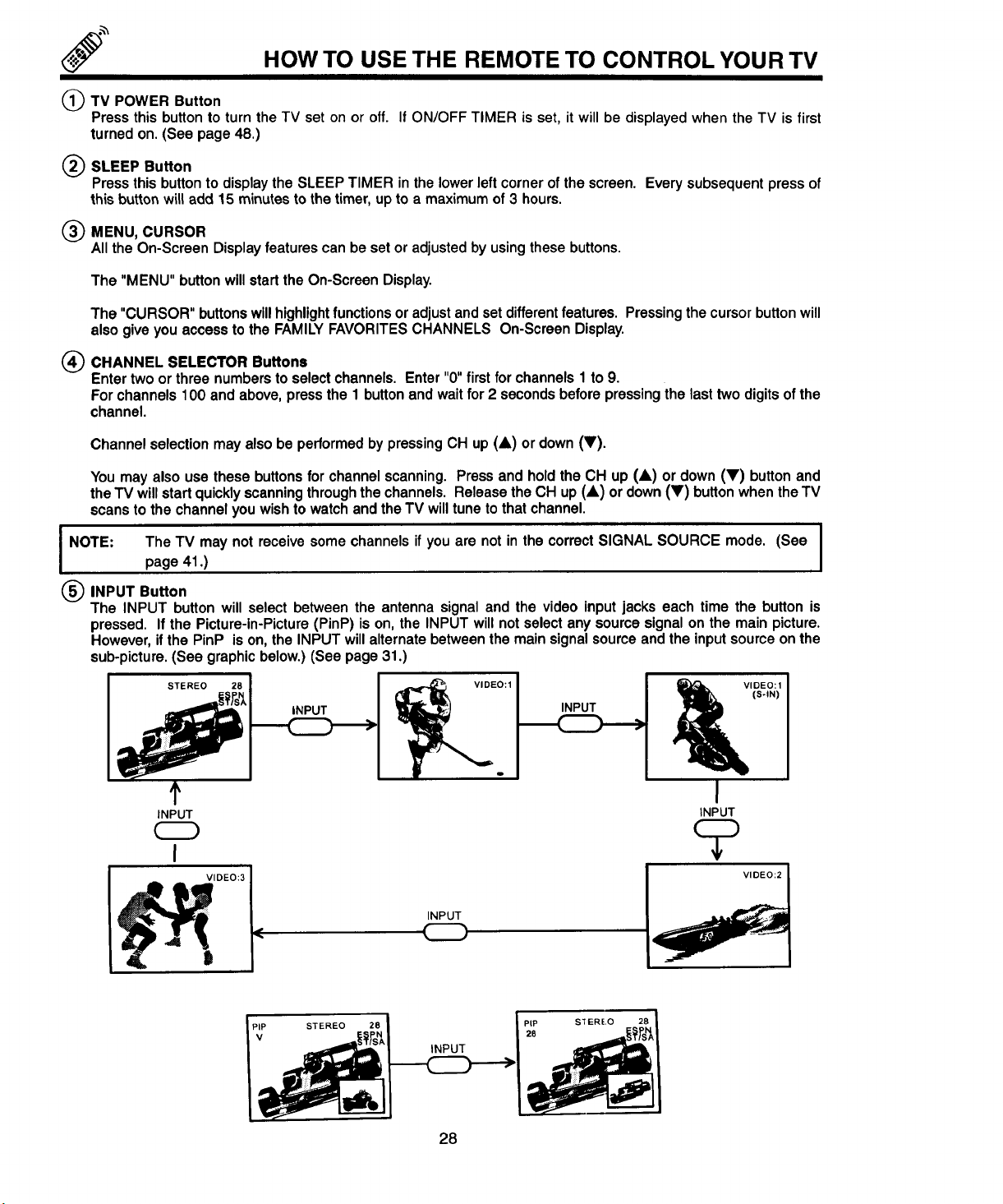
(_TV POWER Button
Press this button to turn the TV set on or off.
turned on. (See page 48.)
(_) SLEEP Button
Press this button to displaythe SLEEPTIMER in the lowerleftcornerofthe screen. Everysubsequentpressof
thisbutton will add 15 minutes tothe timer,upto a maximumof3 hours.
(_) MENU, CURSOR
All the On-Screen Display features can be set or adjusted by using these buttons.
The "MENU" button willstartthe On-ScreenDisplay.
The "CURSOR" buttonswillhighlightfunctionsor adjustandsetdifferentfeatures. Pressingthecursorbuttonwill
alsogiveyouaccessto the FAMILYFAVORITESCHANNELS On-ScreenDisplay.
(_ CHANNEL SELECTOR Buttons
Enter two or three numbers to select channels. Enter "0" first for channels 1 to 9.
For channels 100 and above, press the 1 buttonand wait for 2 seconds before pressing the last two digits of the
channel.
Channel selectionmayalsobe performedbypressing CH up(&) or down(V).
You may also use these buttons for channel scanning. Press and hold the CH up (A) or down (V) button and
the'IV will start quickly scanning through the channels. Release the CH up (A) or down (V) button when the TV
scans to the channel you wish to watch and the TV will tune to that channel.
If ON/OFF TIMER is set, it will be displayed when the TV is first
I NOTE" The TV may n°t receive s°me channels if Y°U are n°t in the c°rrect SIGNAL SOURCE m°de' (SeeIpage 41.)
(_ INPUT Button
The INPUT button will select between the antenna signal and the video input jacks each time the button is
pressed. If the Picture-in-Picture (PinP) is on, the INPUT will not select any source signal on the main picture.
However, if the PinP is on, the INPUT will alternate between the main signal source and the input source on the
sub-picture. (See graphic below.) (See page 31.)
INPUT
f _IDEO:I
t
INPUT
t VIDEO:2
INPUT
I
INPUT
(S-IN)
28
Page 29
HOW TO USE THE REMOTE TO CONTROL YOUR TV
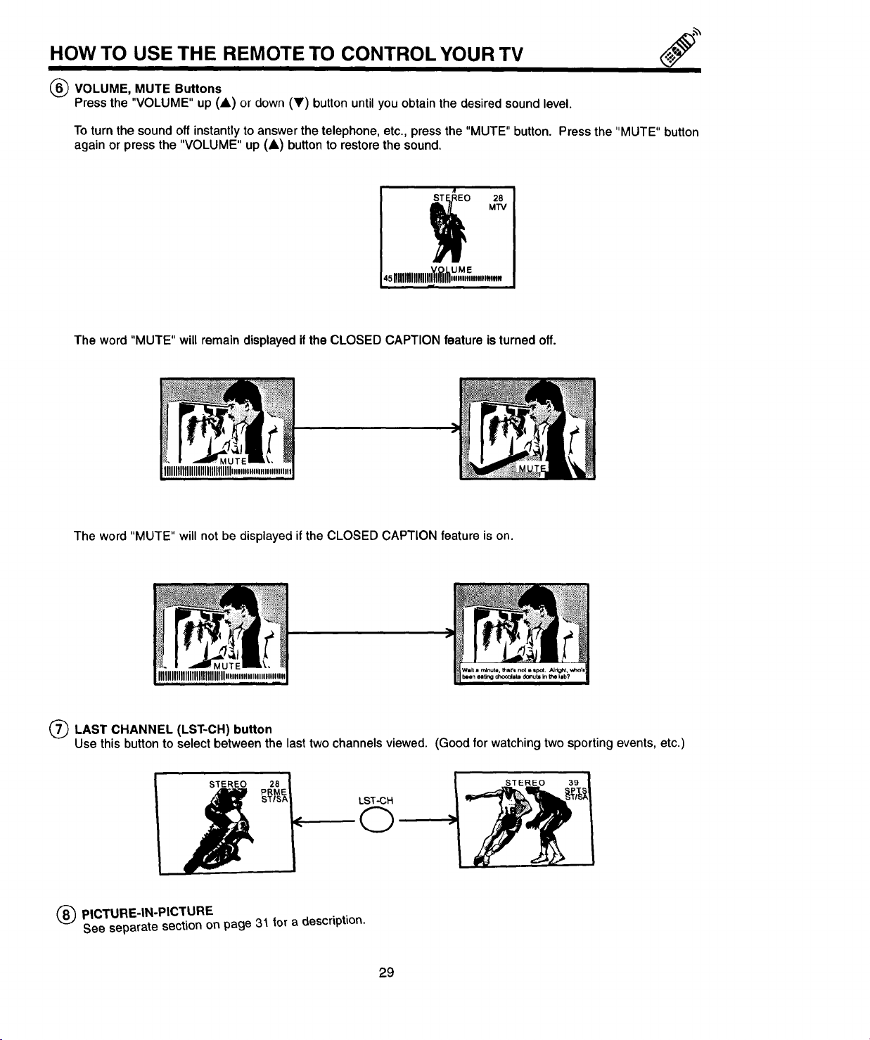
(_ VOLUME, MUTE Buttons
Press the "VOLUME" up (A) or down (Y) button untilyou obtain the desired sound level.
To turn the sound off instantly to answer the telephone, etc., press the "MUTE" button. Press the "MUTE" button
again or press the "VOLUME" up (A) button to restore the sound.
STE _EO 28
4sllllllllllllllllll_l_"""""m
The word "MUTE" will remain displayed ifthe CLOSED CAPTION feature isturned off.
The word "MUTE" will not be displayed if the CLOSED CAPTION feature is on.
M'rv
UME
O LAST CHANNEL (LST-CH)button
Usethisbutton to selectbetweenthe lasttwochannelsviewed. (Goodforwatchingtwosportingevents,etc.)
STEREO
LST-CH
STEREO 39
(D
(_ PICTURE-IN-PICTURE
See separate section on page 31 for a description.
29
Page 30

HOW TO USE THE REMOTE TO CONTROL YOUR TV
(_ LIGHT Button (CLU-418U does not have a light button.)
When you are in a dark room, press this button to light up the volume and channel buttons. The lightwill stay on
for about 8 seconds if no buttons are pressed. The buttons will not appear to light if the room is too bright.
(_) HOME THEATER Button
Press the HOME THEATER button to directly access the SURROUND function. (See page 54.)
(_ EXIT/RECALIJCOMMERCIAL SKIP Button
Press this button when no menu is displayed when you want to check the channel being received, or if it has
stereo (ST) or second audio (SAP).
Youcan alsocheckthe time,CHANNEL ID,and ifthe SLEEPTIME has beenset.
Whenin MENU mode,this buttonwillexitall On ScreenDisplays.
Pressthisbuttontwicequickly,whennomenuisdisplayed,to enabletheCOMMERCIALSKIP (CS)function.This
willtune theTV tothe lastchannelviewedand after30 seconds,tunebacktothe originalchannel.
AudioSelected
,//Antenna Source
/ Channeland
STEREO sN.l_/V_/_ I
Audio
Broadcast
ON TIMER'_:
='ON 7:00 AM TIME
,OFF 9:00 PM 10:1511:
OFF TIMER" I I oooooooI J
If a video input is used:
VideoInput
J
VIDEO:I
(S-IN)
WhenanS-Video
inputisconnected
You can also use the RECALL button to quickly clear many of the other On-Screen Displays.
3O
Page 31
PICTURE-IN-PICTURE
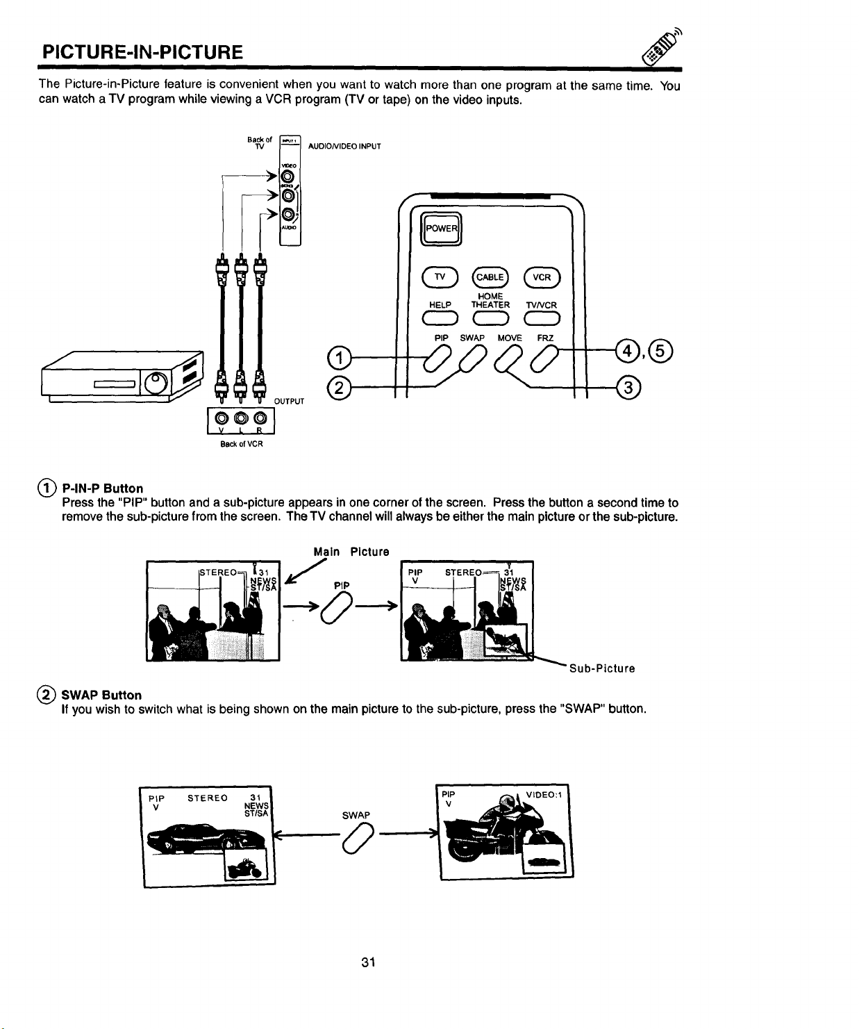
The Picture-in-Picture feature is convenient when you want to watch more than one program at the same time. You
can watch a TV program while viewing a VCR program (TV or tape) on the video inputs.
m
Back of
"IV
-- AUDIO/VIDEO INPUT
,I_EO
o
@1
O"
_uoqo
w
,®
(_ P-IN-P Button
Pressthe "PIP" button anda sub-pictureappearsinonecornerofthescreen. Pressthebutton a secondtimeto
removethesub-picturefrom thescreen.TheTV channelwillalwaysbeeitherthe mainpictureorthe sub-picture.
Main Picture
J PIP STEREO_
SWAP Button
If you wish to switch what is being shown on the main picture to the sub-picture, press the "SWAP" button.
PIP STEREO 31
V NEWS
STISA
_-"'="--'-"- _ _ _1PIP VIDEO:I
PIP
Sub-Picture
31
Page 32

PICTU RE-IN-PICTURE
(_) MOVE Button
To move the sub-picture to any location ofthe screen, press the "MOVE" button once and quickly press the CUR-
SOR buttons.
MOVE CURSOR
To move thesub-picturetoanothercorner,pressthe"MOVE" buttontwicequickly.The sub-picturemovesone
stepcounterclockwiseeverytimethe"MOVE" buttonispressedtwice.
MOVE
_) FREEZE (FRZ) Button
If youwishto freeze the sub-picture,pressthe "FRZ" button.This is convenientwhentryingtowrite downthe
addressfor a mail ordercompany,recordingstatisticsfor a sportingevent,etc. To returnthe picturetomotion,
pressthesame buttonagain.
(_) FREEZE (FRZ) Button (without a sub-picture (PIP OFF))
Press this button without a sub-picture to freeze the picture you are currently viewing. Press this button again to
return to normal viewing. The SWAP button will not work with this FREEZE function.
kEREO 31
FRZ
I ,_CAUTION: A pattern burn maydevelopifthe sub-pictureisleft inthesamecorner permanently.If the PIP
feature is usedfrequently,occasionallymovethesub-picturetoa differentcorner.
1. Onlysoundfromthemainpicturecan beheard.
2. P-IN-P will notworkwitha CHILD LOCKchannelasthe mainpicturebutwillbe displayedasa sub-picture.
NOTE: I
3. Whenthe"PIP" buttonis pressed,thesub-picturewillappearinthesame positionas previouslyset.
32
Page 33
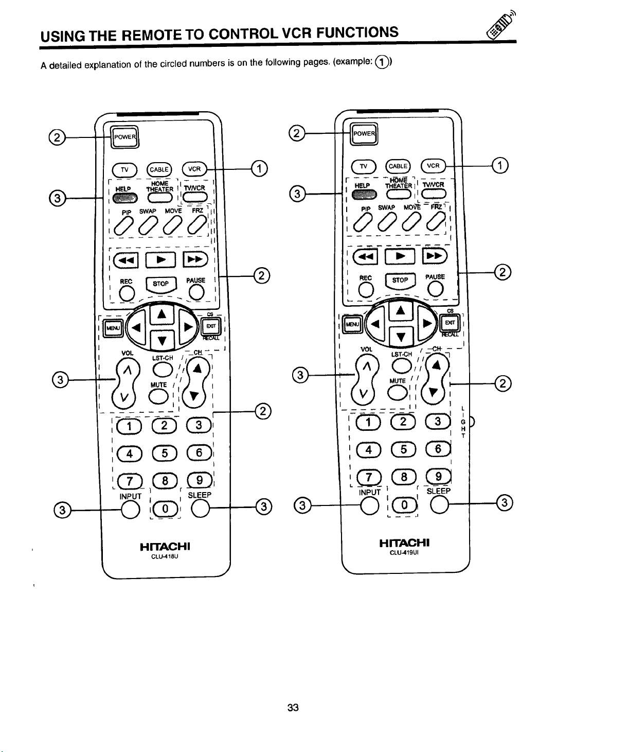
USING THE REMOTE TO CONTROL VCR FUNCTIONS
A detailed explanation of the circled numbers is on the following pages. (example: @)
f
®
®
®
®
HELP THF.ATt=R ]
PIP 5WA_ MOV_--F'RZ _ I
OOO&'
®
I
J
®
®
HITACHI
CLU-q18U
® ®
33
®
HITACHI
CLLI-419UI
Page 34

USING THE REMOTE TO CONTROL VCR FUNCTIONS
Operating the pre-coded function for your VCR
This remote is designed to operate different types of VCR's. You must first program the remote to match the remote
system of your VCR. (Refer to page 37.)
1. Turn on your VCR.
2. Aim the remote control at the front of your VCR.
3. Press the VCR button to switch to the VCR pre-coded mode.
4. While holding down the VCR button on the remote, enter the 2 digit preset code that matches your VCR as shown
on page 37. The remote will turn off your VCR when the correct 2 digit preset code is entered. When this occurs,
the remote control is programmed for your VCR. If the VCR does not turn off after 5 seconds, try a different 2
digit preset code.
5. The remote will now control your VCR.
NOTES:
1. Ifyour VCR cannot be operated after performing the above procedures, this means that your VCR code has not
been precoded into the remote.
2. In the unlikely eventthat yourVCR cannotbe operatedafterperformingthe aboveprocedures,pleaseconsult
yourVCR operatingguide.
3. The remotecontrolwillrememberthe codesyouhaveprogrammedin untilthe batteriesareremoved fromthe
remotecontrol. Afterreplacingthe batteriesrepeattheentireprogrammingprocedurestated above.
4. If your VCR does not have a power function, the remote will issue the CHANNEL UP function.
(_) VCR Button
This allowstheremoteto controlyour VCR by settingittoVCR mode.
(_) PRECODEDVCR buttons
These buttons transmit the chosenprecoded VCR codes. ForsomeVCR's,you mustpressthe RECORD button
twiceto recorda program.
(_) EXCLUSIVE TV buttons
These buttons are for operating the TV.
I NOTE: Refer to the instruction manual of the VCR for operation of the buttons exclusively for the VCR. I
34
Page 35

USING THE REMOTE TO CONTROL CABLE/SATELLITE
BOX FUNCTIONS
A detailed exr.'anation of the circled numbers is on the following pages. (example: @)
®
®
f
®-®i
I
:Q,Q Q
INPUT r SLEEP
O' '
®
®
® Q---
®
®
®
L
f
®
I
:0 (!) (i),'--
f I
:Q_,G_ CZ)
INPUT SLEEP
®
O: ',
!(_)j0
HITACHI
CLU-418U
HITACHI
CLU-419UI
J
35
Page 36

USING THE REMOTE TO CONTROL CABLE/SATELLITE
Operating the pre-coded function for your cable/satellite box.
This remote is designed to operate different types of cable boxes and Digital Satellite Systems. You must first program
the remote to match the remote system in your cable/satellite box. (Refer to page 37.)
1. Turn on your cable/satellite box.
2. Aim the remote control at the front of your cable/satellite box.
3. Press the CABLE button to switch to cable/satellite boxmode.
4. While holding down the CABLE button, enter the 2 digit preset code that matches your cable/satellite box as
shown on page 37. The remote willturn off your cable/satellite box when the correct 2 digit preset code is entered.
When this occurs, the remote control is programmed for your cable/satellite box. If the cable/satellite box does
not turn off after 5 seconds, try another 2 digit preset code.
5. The remote will now control your cable/satellite box.
NOTES:
1. If your cable/satellite box cannot be operated after performing the above procedures, this means that your
cable/satellite box code has not been precoded into the remote.
2. In the unlikely event that your cable/satellite box cannot be operated after performing the above procedures,
please consult your cable/satellite box operating guide.
BOX FUNCTIONS
3. The remotecontrol will rememberthecodesyou haveprogrammed in untilthebatteries are removedfrom the
remotecontrol. Afterreplacingthebatteries,repeattheentireprogrammingprocedurestatedabove.
4. If your cable/satellite box does not have a power function, the remote will issue the CHANNEL UP function.
(_ CABLE Button
This button allows the remote to control your cable/satellite box by setting itto CABLE/SATELLITE mode.
(_ PRECODED CABLE/SATELLITE BOX Buttons
These buttonstransmit the chosen precoded CATV and satellite codes.
(_ TVNCR Button
When the remote is in CABLE/SATELLITE mode, this is the NB button.
_ LST-CHButton
Ifyour cable/satellite box has an enter function, this buttonwill sendthe cable/satellitebox enter code.
(_ CS/EXIT/RECALL Button
if yourcable/satellite boxdoes nothave a last channelfunction, this buttonwillsendtheTV channelrecall code.
(_) EXCLUSIVETV Buttons
These buttons are for operatingtheTV.
36
Page 37

CABLE/SATELLITE AND VCR CODES
CABLE BRAND CODES SATELLITE BRAND CODES
ABC . .01,03, 05, 06, 09, 11, 12, 14, 30
Antronlx ....................... 44
Archer .................. 28, 40, 44
Belcor ........................ 31
Cable Star ..................... 31
Century ....................... 40
Citizen ........................ 40
Colour Voice ................ 19, 25
Comtronlcs ................. 29, 34
Contec ....................... 15
Dae Ryung .................... 06
Eastern ....................... 02
Electricord ..................... 37
Everquest ..................... 13
Focus ........................ 57
Garrard ....................... 40
GO Electronics ............... 31, 44
Gemini ............... 13, 32, 36, 46
General Instrument ........... 09, 51
GoldStar ................... 29, 39
Hamlin ............ 08, 16, 27, 49, 50
Hitachi ........................ 09
Hytex ......................... 05
Jasco ........................ 40
Jerrold ...... 03, 09, 10, 12, 13, 30, 51
Macom ....................... 26
Magnavox ..................... 21
Memorex ...................... 00
Movie Time .............. 35, 37, 42
NSC ................... 35, 37, 42
Oak .................... 05, 15, 47
Panasonic ............... 00, 17, 38
Paragon ....................... 00
Philips ............ 19, 21, 22, 23, 24,
................... 25, 40, 46, 54
Pioneer ................. 18, 39, 65
Popular Mechanics .............. 57
Pulsar ........................ 00
RCA ......................... 17
Realistic ...................... 44
Recoton ....................... 57
Regal ................ 16, 49, 50, 53
Regency ...................... 02
Rembrandt .................. 09, 36
Runco ........................ 00
Samsung ................... 29, 39
Scientific Atlanta ....... 04, 06, 14, 52
Signal ..................... 13, 29
Signature ...................... 09
SL Marx ....................... 29
Sprucer .................... 17, 55
Starcom ................. 03, 13, 30
Stargate .................... 13, 29
Starquest ...................... 13
StarSight ................... 58, 59
Sylvania ...................... 01
Teleview ...................... 29
Texscan ....................... 01
Tocom .................. 10, 11, 33
Toshiba ....................... 00
Tusa ......................... 13
TV86 ......................... 35
Unika ...................... 40, 44
United Artists ................... 05
United Cable ................... 03
Universal ....... 28, 31, 37, 40, 43, 44
Videoway ...................... 48
Viewstar .............. 21, 34, 35, 45
Zenith ..................... 00, 64
Zentek ......................... 57
General Instrument .............. 61
Jarrold ..................... 61, 62
Primestar ................... 61, 62
RCA ......................... 60
Sony ......................... 63
TELEVISION BRAND CODES
Hitachi ........................ 00
Megatron ...................... 00
VCR BRAND CODES
Adventura ..................... 00
Aiko .......................... 50
Aiwa ......................... 00
Akai .................... 14, 23, 49
American High .................. 09
Asha ......................... 48
Audiovox ...................... 10
Beaumark ..................... 48
Bell & Howell ................... 30
Brandt ........................ 38
Broksonlc .......... 33, 37, 43, 51, 52
Calix ......................... 10
Canon ........................ 09
Capehart ...................... 05
Carver ........................ 28
CCE ...................... 27, 50
Citizen ..................... 10, 50
Colt .......................... 27
Craig ................ 10, 19, 27, 48
Curtis Mathes ............ 09, 14, 22
Cybernex ...................... 48
Daewoo ........... 03, 05, t7, 29, 50
Daytron ....................... 05
Dynatech ...................... 00
Electrohoma ................... 10
Electrophonlc ................... 10
Emerex .... •................... 06
Emerson .... 00, 01, 10, 16, 23, 33, 37,
........... 40, 41,43, 44, 50, 51, 52
Fisher ............... 19, 21, 25, 30
Fuji ....................... 07, 09
Funai ......................... 00
Garrad ........................ 00
GE .................. 09, 22, 24, 39
Goldstar ................. 04, 10, 11
Gradiente ..................... 00
Harley Davidson ................ 00
Harman/Kardon ................. 11
Harwood ...................... 27
Headquarter ................... 18
HI-Q ......................... 19
Hitachi ............... 14, 15, 24, 31
Jensen ....................... 14
JVC .................... 02, 14, 26
KEG ...................... 10, 50
Kenwood ................ 11, 14, 26
KLH .......................... 27
Kodak ...................... 9, 10
Lloyd ......................... O0
Lloyd's ........................ 40
Logik ......................... 27
LXI .......................... 10
Magnovox .......... 09, 12, 28,32, 34
Magnln ....................... 48
Marantz .................... 09, 28
Marta .......................
Matsushita ..................... 09
VCR BRAND CODES
(Cont.)
MEI .......................... 09
Memorex .......... 00, 09, 10, 12, 18,
................... 19, 20, 30, 48
MGA ...................... 16, 23
MGN Technology ................ 48
Minolta .................... 15, 31
Mitsubishi .......... 16, 23, 26, 36, 49
Motorola ................... 09, 20
MTC ...................... 00, 48
Multitech ................... 00, 27
NEC .............. 11, 13, 14, 26, 30
Nikko ......................... 10
Noblex ........................ 48
Olympus ................... 09, 47
Optimus ................. 10, 20, 30
Orion ......................... 51
Panasonic ......... 09, 35, 46, 47, 53
Penney ...... 09, 10, 11, 13, 15, 21, 48
Pentax .................. 15, 24, 31
Philco ........................ 09
Philips ................ ...09, 28, 32
Pilot .......................... 10
Pioneer ....................... 26
Portland ....................... 05
Protec ........................ 27
Pulsar ........................ 12
Quarter ....................... 18
Quartz ........................ 18
Quasar ....................... 09
Radio Shack ................ 00, 10
Radix ......................... 10
Randex ....................... t 0
RCA ........... 15, 22, 24, 31, 34, 39
Realistic .......... 00, 09, 10, 18, 19,
................... 20, 25, 30, 48
Ricoh ......................... 08
Runco ........................ 12
Samsung ................... 17, 48
Sanky ..................... 12, 20
Sansui ..................... 14, 26
Sanyo ............... 18, 19, 30, 48
Scott .......... 16, 17, 33, 37, 43, 44
Sears ............ 09, 10, 15, 18, 19,
................... 21, 25, 30, 31
Sharp ........................ 20
Shintom ....................... 27
Shogun ....................... 48
Singer ........................ 27
Sony ................ 06, 07, 08, 09
STS .......................... 15
Sylvania ........... 00, 09, 16, 28, 32
Symphonic .................... 00
Tatung ........................ 14
Teac ...................... 00, 14
Technics ................... 09, 35
Teknika ................. 00, 09, 10
Telefunken ..................... 38
TMK ...................... 40, 48
Toshiba .............. 16, 17, 25, 44
Totevision .................. 10, 48
Unitech ....................... 48
Vector ........................ 17
Vector Research ............. 11, 13
Video Concepts ........... 13, 17, 23
Videosonic ..................... 48
Wards ......... 00, 09, 15, 19, 20, 22,
................... 27, 34, 44, 48
XR-1000 ................ 00, 09, 27
Yamaha ....................... 11
Zenith .................. 07, 08, 12
.10
37
Page 38

COLOR GRAPHIC GUIDE
With Hitachi's new On-Screen Display, each category has it'sown color and Icon. This new semitransparent system
incudes SET-UP, CUSTOMIZE, VIDEO, AUDIO, and INFO CENTER categories. Using the four cursor buttons, you
can easily access and control all of the TV's functions. We also have computer-like check boxes so that you always
know which function you've chosen. You can even choose to access the menu in English, French, or Spanish.
1. Press MENU on the remote control to display the different features on
your HITACHI TV.
2. Press the CURSOR buttons to highlight and select different features.
3. Press EXIT on the remote control to quickly exit from a menu.
4. PressHELP onthe remotecontrolwhena menuis displayed,andtext
willappeargivinga descriptionof thatmenu.
This part of the screen shows
what selections are available.
sETup
I_ CUSTOMIZE
[_ VIDEO
[_ AUDIO
INFO.
CENTER
• EXIT
This part of the screen shows which
remote control buttons to use.
TO JI,.SELECT
MOVE
• (QUIT MENU
CURSOR
cs
RECALL
HELP
1
AUTOMATIC DEMONSTRATION
This feature will demonstrate how to use and set up your HITACHI television. To perform this feature, press the front
panel POWER button and hold for 5 seconds. The On-Screen Display will appear on your TV set demonstrating the
settings of your TV feature.
To exit AUTOMATIC DEMONSTRATION, press the power button on the front panel of the TV, which will turn the TV
off. Press the power button again to turn your TV set on and resume normal operation.
On some televisions, the "SHIFT" and "EXCHNG" that appear during the Automatic Demonstration are
equivalent to the "MOVE" and "SWAP" button respectively on your remote control.
NOTE:
In most cases, the MENU button is used to enter and exit the On-Screen Display.
38
I 000000 I
Page 39

COLOR GRAPHIC GUIDE
MENULANGUAGE
SlGNALSOURCE
AUTO CHANNEL SET
f
CHANNELADD/DEL
CHANNELLIST
CLOCK SET
CUSTOMIZE _ ICHILDLOCK
I
ION/OFF TIMER
ICLOSED CAPTION
CONTRAST
BRIGHTNESS
COLOR
v'°'° I
"_ TINT
SHARPNESS
COLOR TEMP.
RESET
BASS
TREBLE
BALANCE
RESET
ADVANCED
SETTINGS
VOLUME
CORRECTION
SURROUND
Choose English,French,or Spanish language.
Select Antenna or cable TV.
First time set up for channel buttons.
Add or delete channel.
Check channel name, scan, and child lock.
Set before using timer features.
Label channels PAY1, ABC, etc.
Store family favorites channels.
Block channel picture and sound.
Turn TV on or off once, daily, or weekly.
Feature todisplay dialogue/text.
Adjust contrast.
Adjustbrightness.
Adjustcolor.
Adjusttint.
Adjust sharpness.
Adjust warm (red tones) or cool (blue tones).
Set VIDEO to factory preset condition.
Adjust bass.
Adjust treble.
Adjust balance.
Set AUDIO settings to factory preset condition.
Improve sound performance.
Lower volume on selected channels.
Special sound effects.
J_ INFO.
CENTER
I MESSAGES 1
39
Used to leave message or daily reminder.
Page 40

tons on the remote to highlight the function desired.
Select SET-UP when setting your TV up for the first time.
SET-UP
Use the CURSOR A,V but-
I MENU LANGUAGE I This feature will allow you to select any one of 3 different languages for all On-Screen
I
Displays.
__TSET-UP
[_ CUSTOMIZE
[_ VIDEO
auo,o
[_ INFO.
CENTER
• TO •SELECT ' _ )1
• MOVE (QUIT MENU
SET-UP 1
MENU LANGUAGE ___
SIGNAL SOURCE |
AUTO CHANNEL SET |
CHANNEL ADD/DEL |
CHANNEL LIST |
CLOCK SET |
t_ to ,SE'ECT _xiT I
MOVE • BACK (QUIT MENU)J
CURSOR
ENGLISH
FRANCAIS
MENU LANGUAGE /
D ESPANOL
TO EXIT
MOVE • BACK (QUIT MENU)
UseCURSOR • or • to selectthe MENU LANGUAGEofyourchoice.
PressEXIT toquitmenuorCURSOR • to returntopreviousmenu.
40
Page 41

SET-UP
SlGNALSOURCE
ICURSOR
I Select ANTENNA if you are using an indoor or outdoor antenna. Select CATV if you have
cable TV.
I _'SET-UP
_ CUSTOMIZE
!_ VIDEO :
_-] AUDIO
_] INFO:
CENTER
• TO _SELECT _T _
• MOVE (QUI'I" MENU
MENU lANGUAGE
SIGNAL SOURCE
AUTO CHANNEL SET
CHANNEL ADD/DEL
I ET.UP t
CHANNEL LIST
CLOCK SET
[€ MovETO _I,_SELECT (QUITMENUI:,_BACK
EXIT
CURSOR
_I_IANTENNA
SIGNAL SOURCE 1
: nCATV1[]CA:W2 ::.:
t,= To exrr ]
[• MOvE < BACK (QUIT MENU)]
Press CURSOR • or • to highlight and select the correct SIGNAL SOURCE mode.
Press EXIT to quit MENU or CURSOR ,q to return to previous menu.
RECEPTION BAND
CATV 1 OR CATV 2
ANTENNA
CATV CHANNEL Indicated on
Reception channels for each mode are shown at the
left.
the screen
VHF 2 ~ 13ch
UHF 14 ~ 69ch
VHF 2 ~ 13
Mid band A - I
A-5 ~ A-1
Super Band J ~ W
Hyper band
W+I -W+28
Ultra band
2-13
14 - 22
95 ~ 99
23 ~ 36
37 - 64
65 -125
Refer to your cable or TV guide for channel identifi-
cation standards.
If certain CATV channels are poor or not possible in
CATV1 mode, set SIGNAL SOURCE to CATM2.
W+29~W+B4
41
Page 42
SET-UP
i i
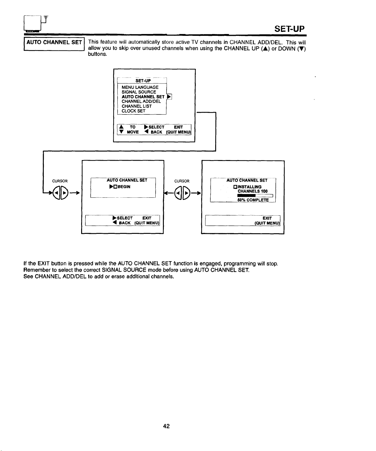
I AUTO CHANNEL SET I This feature will automatically store active TV channels in CHANNEL ADD/DEL. This will
I
allow you to skip over unused channels when using the CHANNEL UP (A) or DOWN (V)
buttons.
SET-UP 1
MENU LANGUAGE J
SIGNAL SOURCE I._..
AUTO CHANNEL SET
CHANNEL ADD/DEL |
CHANNEL LIST |
CLOCK SET J
I A TO _1_SELECT EXIT )}
• MOVE • BACK (QUIT MENU
AUTO CHANNEL SET
_I_r'IBEOIN
SELECT EXIT 1
BACK (QUIT MENU)]
CURSOR
AUTO CHANNEL SET
[] INSTALLING
CHANNELS 100
50% COMPLETE
(QUIT MENU) I
EXIT 1
If the EXIT button is pressed while the AUTO CHANNEL SET function is engaged, programming will stop.
Remember to select the correct SIGNAL SOURCE mode before using AUTO CHANNEL SET.
See CHANNEL ADD/DEL to add or erase additional channels.
42
Page 43
SET-UP
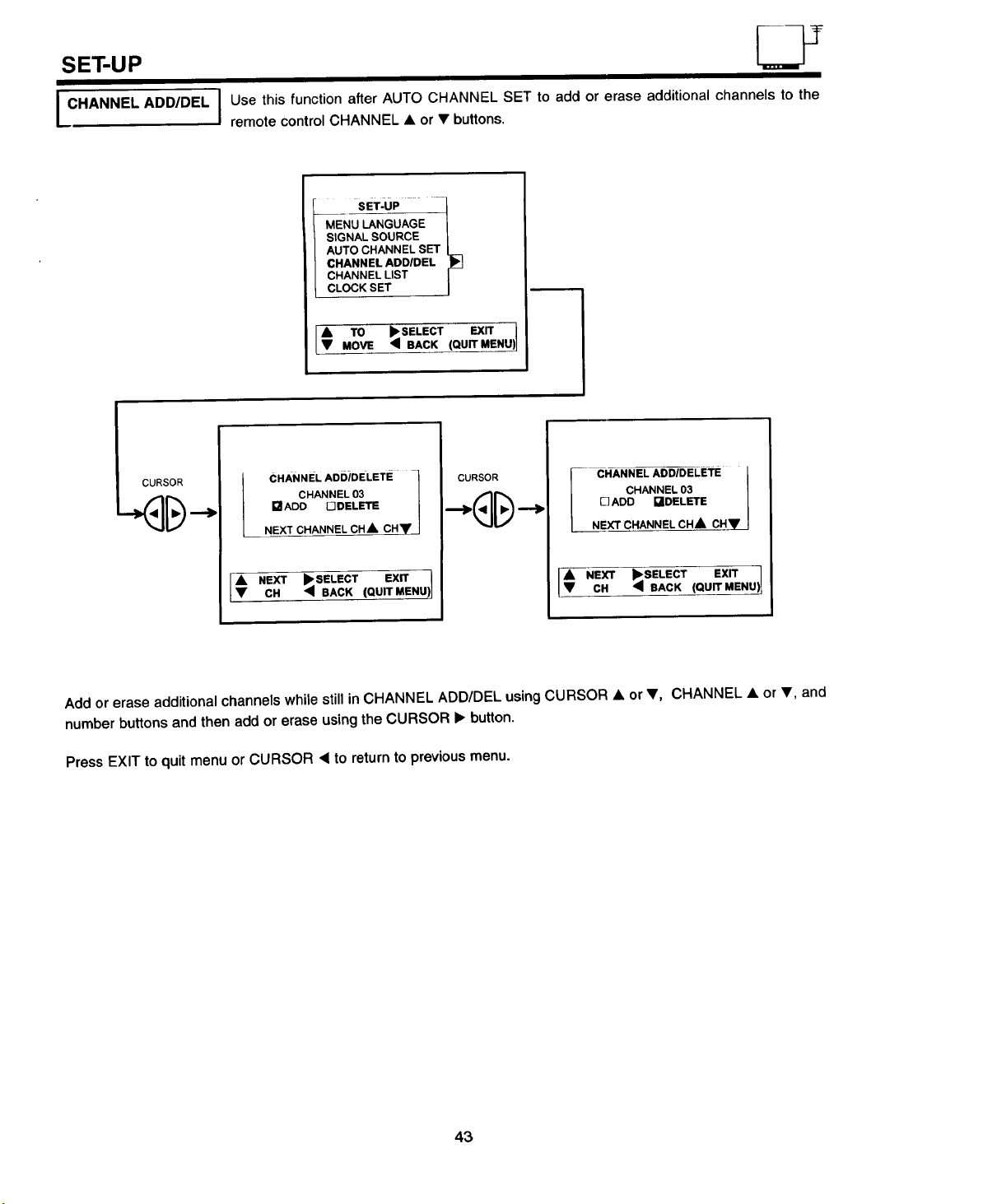
I CHANNEL ADDJDEL I
I CURSOR
Use this function after AUTO CHANNEL SET to add or erase additional channels to the
remote control CHANNEL • or • buttons.
MEN
SIGNAL SOURCE
AUTO CHANNEL SET
CHANNEL ADD/DEL
I sET-uP " 1
CHANNEL LIST
CLOCK SET
• TO _SELECT EXIT
MOVE '_BACK (QUITMENU) 1
CHANNEL ADD/DELETE -}
CHANNEL03 /
aADD _DELETE /
NEXT CHANNEL CHkCHy/
CURSOR
CHANNEL ADD/DELETE
CHANNEL 03
DADD I_IDELETE
NEXT CHANNEL CH A CH_p'
I€ NEXT •SELECT EX_
CH _ BACK (QUITMENU)
NEXT •SELECT EXIT 1
CH _ BACK (QU_
Add or erase additional channels while still in CHANNEL ADD/DEL using CURSOR • or •, CHANNEL • or •, and
number buttons and then add or erase using the CURSOR • button.
Press EXIT to quit menu or CURSOR • to return to previous menu.
43
Page 44

SET-UP
I CHANNEL LIST
This function allows you to view which channels are labeled in CHANNEL ID (NAME), which
have been added to CHANNEL ADD/DEL (SCAN), and which are protected by CHILD
LOCK (LOCK).
M-ENU_QUAQE _!
S#GNALSOURCE!
CURSOR
AUTOCHANNELSEt!
CHANNEL ADD/DEL
CHANNEL LIST _J
CLOCK SET J
_-MoTOE _ SELECT EXIT
Press CURSOR • or • to view more channels.
Press EXIT to quit menu or CURSOR • to return to previous menu.
CLOCK SET
• BACK (QUIT MENU_j
JUse this feature for all time related functions. The time must be set before you can use the
ON/OFF TIMER or MESSAGE.
CHANNEL LIST
CH NAME SCAN LOCK
01 USA ON -
02 ROLY ON -
03 TESS - ON
.... JAYB .,., ON
05JEK0 ,-,,, i "t"
t O EXiT J
MOVE •eACK (aUrrMe.u)J
-- SET-UP -- 1
MENU LANGUAGE |
SIGNAL SOURCE
/
CURSOR
AUTOCHANNELSET I
CHANNELADD/DEL[
CHANNELLIST I_
CLOCKSET I_l
[A, TO _SELECT _
MOVE •BACK (QUITMENU1
LT
Use CURSOR • or • buttons to set the time and AM or PM.
Press CURSOR • to change position.
Press EXIT to quit menu or CURSOR • to return to previous menu.
I CLOCK SET }
TIME 12 : O0 PM
It TO I_SELECT EXIT ]
SET • BACK (QUITMENU)!
44
Page 45
CUSTOMIZE
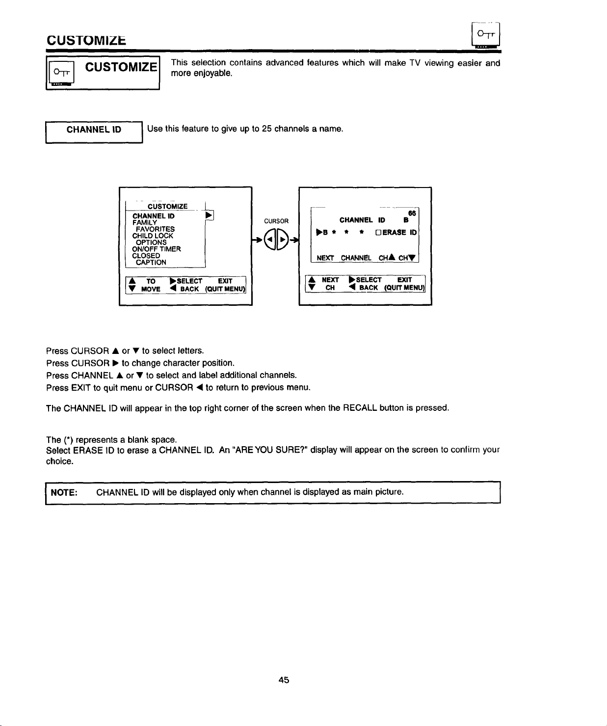
CUSTOMIZE
This selection contains advanced features which will make TV viewing easier and
more enjoyable.
CHANNEL ID
I
Use this feature to give up to 25 channels a name.
CHANNEL ID
FAMILY
FAVORITES
CHILD LOCK
OPTIONS
ON/OFF TIMER
CusTOMIzE l
CLOSED
CAPTION
A TO _I, SELECT EXIT
• MOVE • BACK (QUIT MENU)
CURSOR
CHANNEL ID B
Ib'B * * * D ERASE IO
i 66
NEXT CHANNEL CHA CH•
f NEXT _'$ELECT EXIT
CH • BACK (QUIT MENU)
Press CURSOR • or • to select letters.
Press CURSOR • to change character position.
Press CHANNEL • or • to select and label additional channels.
Press EXIT to quit menu or CURSOR • to return to previous menu,
The CHANNEL ID will appear in the top right corner of the screen when the RECALL button is pressed.
The (*) represents a blank space.
Select ERASE ID to erase a CHANNEL ID. An "ARE YOU SURE?" display will appear on the screen to confirm your
choice.
I NOTE: CHANNEL ID will be displayed only when channel is displayed as main picture.
45
Page 46
CUSTOMIZE
JFAMILY
FAVORITES
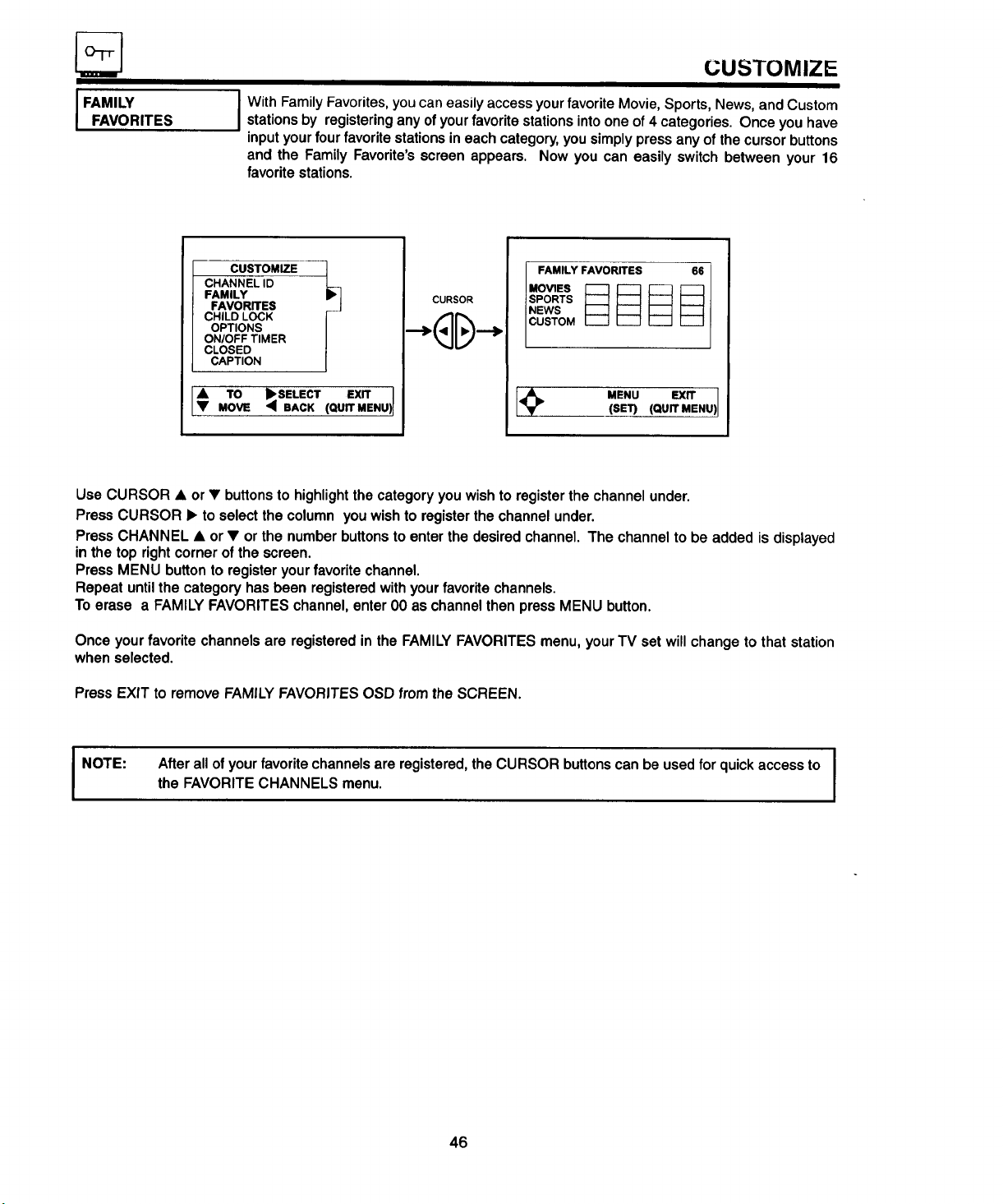
I With Family Favorites, you can easily access your favorite Movie, Sports, News, and Custom
stations by registering any of your favorite stations into one of 4 categories. Once you have
input your four favorite stations in each category, you simply press any of the cursor buttons
and the Family Favorite's screen appears. Now you can easily switch between your 16
favorite stations.
CHANNEL ID
FAMILY
FAVORITES
CHILD LOCK
OPTIONS
ONIOFF TIMER
CUSTOMIZE 1
CLOSED
CAPTION
€ To ExrrI
MOVE (QUIT MENU)I
CURSOR
FAMILY FAVORITES 66
SPORTS
NEWS
CUSTOM
MENU EXIT(SET) (QUIT MENU)
Use CURSOR • or • buttons to highlight the categoryyou wishto registerthechannelunder.
PressCURSOR • to selectthecolumn youwishtoregisterthechannelunder.
PressCHANNEL• or • or the numberbuttonsto enterthe desiredchannel.The channelto be added is displayed
inthetop rightcornerof the screen.
PressMENU buttontoregisteryourfavoritechannel.
Repeat untilthe categoryhasbeen registeredwithyourfavoritechannels.
To erase a FAMILYFAVORITESchannel,enterO0as channelthenpressMENU button.
Once yourfavorite channelsare registeredin the FAMILYFAVORITESmenu,yourTV set willchange to thatstation
whenselected.
Press EXIT to remove FAMILY FAVORITES OSD from the SCREEN.
Afterall of yourfavorite channelsareregistered,theCURSOR buttonscan be usedfor quickaccessto
I NOTE:
the FAVORITECHANNELSmenu.
46
Page 47
CUSTOMIZE
I
I CHILD LOCK
OPTIONS
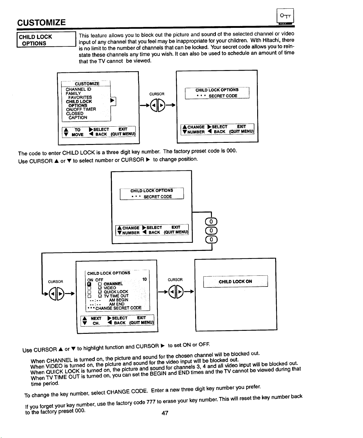
I This feature allows you to block out the picture and sound of the selected channel or video
input of any channel that you feel may be inappropriate for your children. With Hitachi, there
_sno limit to the number of channels that can be locked. Your secret code allows you to rein-
state these channels any time you wish. It can also be used to schedule an amount of time
that the TV cannot be viewed.
FAMILY
FAVORITES
CHILD LOCK
OPTIONS
ON/OFF TIMER
" CUSTOMiZe
CLOSED
CAPTION
,& TO _SELECT EXIT
• MOVE _ BACK (QUIT MENU)
CURSOR
I CHILD LOCK OPTIONS ._
* * * SECRET CODE ..
l ACHANGE "SELECT EXiT ]
• NUMBER 4 BACK QU_Uff_MEN_
The code to enter CHILD LOCK is a three digit key number. The factory preset code is 000.
Use CURSOR • or • to select number or CURSOR • to change position.
CHILD LOCK OPTIONS ]
* * * SECRETCODE
I ACHANGE ,SELECT (QUIT MENU)]
IVNUMBER '_ BACK
EXIT
(Z)
I
ICURSOR
CHILD LOCK OPTIONS
ON OFF
CHAN"E V,DEO
[] [] QUICK LOCK
I-3 [] TM TIME OUT
.. : - - AM BEGIN
-- : - - AM END
* * * CHANGE SECRET CODE
CURSOR
I CHILD LOCK ON t
I¢N r .EL,CTEXIT)]CH. :_ BACK (QUIT MENU
Use CURSOR • or • to highlight function and CURSOR • to set ON or OFF.
When CHANNEL is turned on, the picture and sound for the chosen channel will be blocked out.
When VIDEO is turned on, the picture and sound for the video input will be blocked out.
When QUICK LOCK isturned on, the picture and sound for channels 3, 4 and all video input will be blocked out.
When TV TIME OUT is turned on, you can set the BEGIN and END times and the TV cannot be viewed during that
time period.
To change the key number, select CHANGE CODE. Enter a new three digit key number you prefer.
If you forget your key number, use the factory code 777 to erase your key number. This will reset the key number back
to the factory preset 000. 47
Page 48

• I
I I I I
CUSTOMIZE
I ON/OFF TIMER
J Th_s functfon will automatically turn the TV set on or off one time only, every day, or once a
week. It can also be set to turn on to your favorite program, or as a reminder, to turn to your
favorite program when the TV is already on.
CHANNEL ID
FAMILY
FAVORITES
CHILD LOCK
OPTIONS
ONIOFF TIMER
CUSTOMIZ I-= t
CLOSED
CAPTION
[_ MovETO _I_;_SELECTBAcK(Qu_'X_Nu)
CURSOR
[;.ov,'O °o..o.o,j
ON/OFF TIMER
_ o-,--AM TVON
--: --AMTV OFF
CHANNEL 03
[] ONCE
[3 DAILY
[q WEEKLY
[] OFF
EXIT
Press CURSOR • or • to select either the ON or OFF TIMER.
Press CURSOR • to highlight selection to be changed.
Press CURSOR • or • to select the time the TV will turn on and off and to choose AM or PM.
Press CURSOR • to exit time setting.
Select CHANNEL and press CHANNEL • or • to set the channel the TV will tune to when it automatically turns on.
Press CURSOR • to exit channel setting.
Press CURSOR • or • to highlight then CURSOR • to select mode: ONCE(one time only), DAILY(every day), or
WEEKLY(once a week).
NOTE:
You can set either on time only or off time only, or both. The mode will be the same for both.
If the TV is turned on due to ON TIMER and there is no remote control operation in 3 hours or more,
the TV will automatically turn off.
Oo not use your TV as a deterrent when away from home by using both the ON TIMER and
I A CAUTION:
OFF TIMERS. For safety, the TV shoutd be turned ott when you are away from home.
48
Page 49

CUSTOMIZE
I CLOSED
CAPTION
I Closed captions are the dialogue, narration, and/or sound effects of a television program or
home video which are displayed on the TV screen allowing you to read the dialog being
spoken (when broadcast). Your localTV program guide denotes these programs as [] or
13
CUSTOMIZE I
CHA_
FAMILY I
FAVORITES I
CHILDLOCK . J
OPTIONS
ON/OFF TIMER L_
CLOSED _,|
CAPTION
sxrr
€ TO _I_SELECT (QU EX_
MOVE _ BACK .....
DISPLAY: ON/OFF willturnthe[] displayon oroff.
MODE: C.C. (ClosedCaption)isforthe programyouareviewing.
MODE: TEXT is foradditionalinformationsuchas newsreportsor a TV programguide. Thisinformation
coversthe entirescreenand viewingtheTV programisnot possible.TEXT may notbe available
withevery[] program.
CURSOR
MOVE BACK (QUrr MENU)I
CHANNEL: 1 isusedfor theprimarylanguage(usuallyEnglish).
CHANNEL: 2 issometimesusedfor a secondlanguage(mayvaryby region).
Use CURSOR & or• to highlightthefunction tobe changed;pressCURSORI_ to changethefunction.
PressEXIT to quitmenuor CURSOR • to returntopreviousmenu.
Wueather Today
nny 70
Weather To mgrrow
A bit cooler 3
Wind Chill -55"
Text Setected
NOTE:
C.C. Setected
will not
MUTE
word
The
make sure MUTE is not set.
be
displayed
Closed Caption Display is ON. If you do not have soun_l,
if the
l
49
Page 50

VIDEO
VIDEO
Select VIDEO to adjust picture settings and improve picture quality.
I
i_ [_SET-UP
I cu..o.,z
t =,EO .u)
A TO •SELECT .......
• MOVE
Use the CURSOR • or • to highlightthe function to be adjusted.
Press CURSOR • or • to adjust the function.
Press EXIT to quit menu or CURSOR • to return to previous menu.
CONTRAST
Use this function to change the contrast between black and white levels in the picture.
BRIGHTNESS
Use this function to adjust overall picture brightness.
CENTER
(Qurr
CONTRAST •".=m._-
BRIGHTNESS "'""""'"'1""",'.,..,
COLOR "".".".1"......,,
TINT i'"""iili""H""'"
SHARPNESS ,i!,,,,..,,,,I,,,,.,,,,,,..
COLOR TEMP. I_IWARM
RESET []
• MOVe 4ADJUST(QUrrMENU)
DCOOL
COLOR
Use this function to adjust the level of color in the picture.
TINT
Use this function to adjust flesh tones so they appear natural.
SHARPNESS
Use this function to adjust the amount of fine detail in the picture.
COLOR TEMP.
Use this function to adjust the white balance (hue) of the picture to your own color preference.
When shipped from the factory, this is set to "COOL". If you prefer a reddish screen, set to "WARM".
RESET
When RESET is selected, the "ARE YOU SURE?" display will appear on the screen to confirm your choice.
CURSOR.• to return VIDEO adjustments to factory preset conditions.
If CONTRAST is selected you are adjusting CONTRAST, the additional menu items COLOR, TINT,
BRIGHTNESS, SHARPNESS, and RESET can be viewed on the screen and can also be adjusted by
I NOTE:
scrolling through them using the CURSOR • orV. This is also true for all of the menu items in VIDEO.
50
Press
Page 51

AUDIO
Select AUDIO to adjust the TV to your preference and to improve the sound quality.
J
1
I_ °'-'+"°'+"=I
II_ v'°'=° L_,
CURSOR
BASS _ _,
TREBLE ...........m,l,.,.m,,......
BALANCE .".m..,l,,.,.",,m,,
RESET '1"3
_vA.cE
SE'B'INGS
tI_ ,.o,o
SURROUND :i
I[_ '0";%. i
€ MovETO _SELECT (QUITMENU) I
Use the CURSOR • or • to highlight the function to be adjusted.
Press CURSOR • or • to adjust the function.
Press EXIT to quit menu or CURSOR • to return to previous menu.
BASS
This function controlsthe low frequency audioto allspeakers.
TREBLE
This function controls the high frequency audioto all speakers.
BALANCE
Thisfunction will controlthe left to right balanceofthe TV internalspeakersandthe AUDIOTO HI FI output.
EXIT
J¢
TO _ TO (QUIT MENU)JMOVE ADJ.
RESET
When RESET is selected, the "ARE YOU SURE?" display will appear on the screen to confirm your choice. Press
CURSOR • to return AUDIO adjustments to factory preset conditions.
i
NOTE:
If BASS is selected you are adjusting BASS, the additional menu items TREBLE, BALANCE, and
RESET can be viewed on the screen and can also be adjusted by scrolling through them using the
CURSOR • or •. This is also true for all of the menu items in AUDIO.
51
Page 52
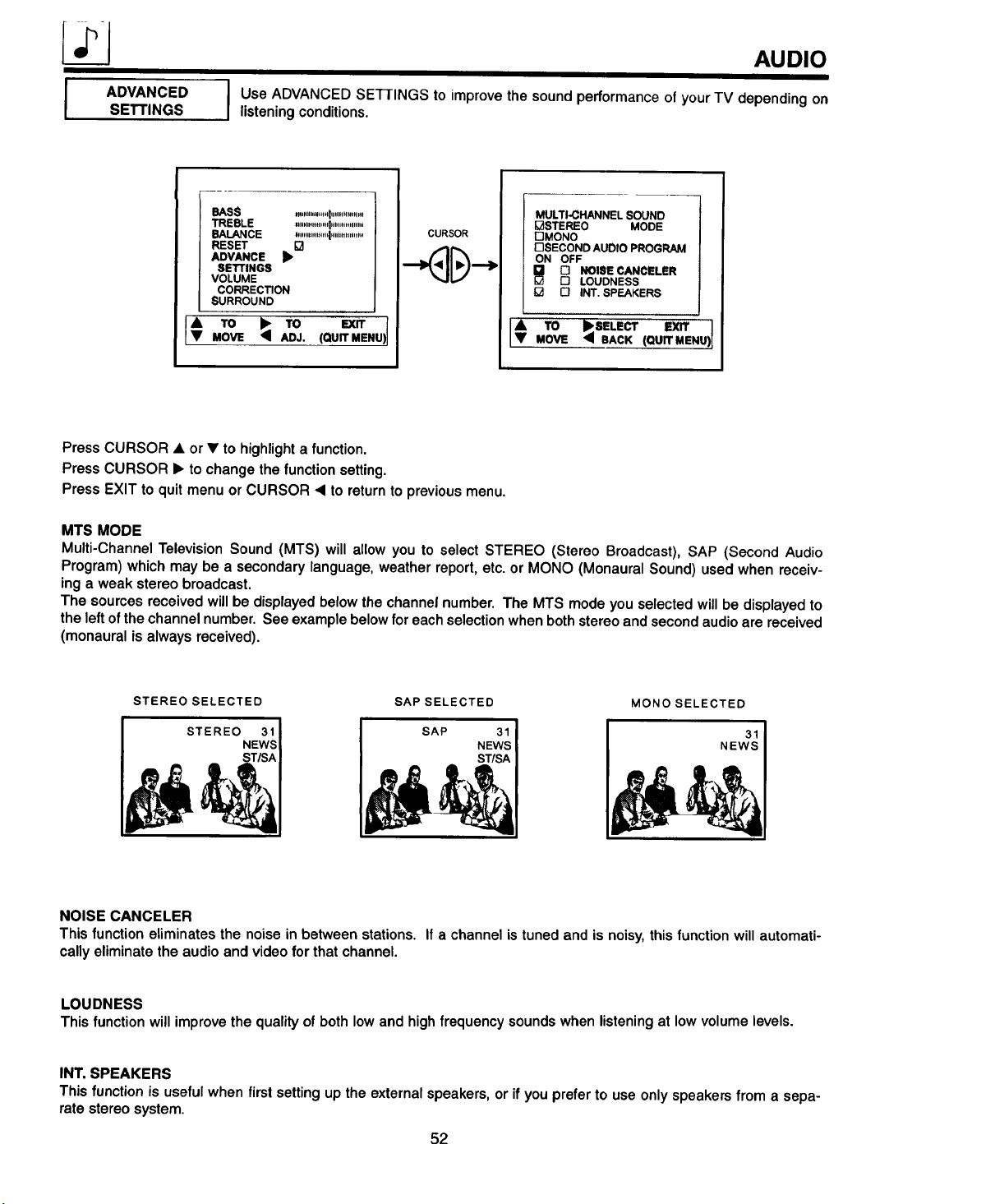
AUDIO
I ADVANCED
SETTINGS
I se ADVANCED SEI-rlNGS to improve the sound performance of your TV depending on
listening conditions.
BASS "_""'"_l""""'"_"_
TREBLE "'" ..........I'""""".....
BALANCE "'"'""'" "'1""'""""
RESET []
ADVANCE
SEI"rlNGS
VOLUME
CORRECTION
SURROUND
; To ; ,o ,°U-%NU,
MOVE ADJ.
CURSOR
MULTI-CHANNEL SOUND
I_STEREO MODE
I-'JMONO
I-ISECOND AUDIO PROGRAM
ON OFF
[] NOISE CANCELER
[] LOUDNESS
O INT. SPEAKERS
IA To I_SELECr F.xrr
• MOVE _ BACK (QUIT MENU)
Press CURSOR • or • to highlight a function.
Press CURSOR I_ to change the function setting.
Press EXIT to quit menu or CURSOR • to return to previous menu.
MTS MODE
Multi-Channel Television Sound (MTS) will allow you to select STEREO (Stereo Broadcast), SAP (Second Audio
Program) which may be a secondary language, weather report, etc. or MONO (Monaural Sound) used when receiv-
ing a weak stereo broadcast.
The sources received will be displayed below the channel number. The MTS mode you selected will be displayed to
the left of the channel number. See example below foreach selection when both stereo and second audio are received
(monaural is always received).
STEREO SELECTED SAP SELECTED MONOSELECTED
STEREO 31 SAP 31 31
NEWS NEWS
ST/SA
NOISE CANCELER
This function eliminates the noise in between stations. If a channel is tuned and is noisy, this function will automati-
cally eliminate the audio and video for that channel.
LOUDNESS
This function will improve the quality of both low and high frequency sounds when listening at low volume levels.
INT. SPEAKERS
This function is useful when first setting up the external speakers, or if you prefer to use only speakers from a sepa-
rate stereo system.
52
Page 53

AUDIO
IVOLUME
CORRECTION
Use this function to reduce the volume level of up to four channels that sound loud com-
I
pared to other channels.
BASS IIIIIIltllllflltllllllflfltllllll
TREBLE .,.............I................
BALANCE "..............I'..........'....
RESET
ADVANCE
SETTINGS
VOLUME •
CORRECTION
SURROUND
[VA TO •SELECT eXrtMOVE • BACK (QUIT MENU)!
VOLUME CORRECTION
CH LEVEL
lOO%
lOO%
NEXTCHANNELCHA CHy
lOO%
10
CURSOR
VOLUME CORRECTION
• 80%
NEXT CHANNEL CH• CHV
lOO%
LEVEL
lOO%
1oo%
10
IA TO •SELECT EXIT
I JIi= TO _BELECT EXIT
T MOVE _ BACK (QUIT MENU)
IT ,=uiTME.U)MOVE ;_ BACK
Press CURSOR • or • to highlight one of the four volume corrections, then CURSOR _ to select.
Press CHANNEL • or • and number buttons to select a channel.
Press MENU to set the channel to be volume corrected.
Press CURSOR • or • to adjust volume level in 5% increments.
Press EXIT to quit menu or CURSOR • to return to previous menu.
NOTE:
1. Volume Correction adjustment is for the channel display in the top right corner of the screen. To
adjust a different channel, you must select the channel with the channel or number buttons and
press CURSOR _'.
2. If the channel has been corrected before, use the CURSOR • or • to highlight and CURSOR I> to
select that channel, then use the CURSOR • or • to change the level.
3. To erase a channel from volume correction, select channel 00 and press MENU.
4. The volume level will change from 50% to 100% in increments of 5%.
53
Page 54

iii ii
AUDIO
I SURROUND
I
CURSOR
I he following surround sound settings will reproduce the "live" sound you would hear in
concert halls, movie theaters, etc. when you set up your speaker system as shown in the
section on rear panel connections on pages 20, 21 and 24. The surround system is most
effective with movies played on a stereo VCR.
Surround sound allows the viewer to enjoy sound which provides a feeling of "Presence"
from stereo broadcasts and VCR tapes recorded with stereo sound. Also a mono input,
simulating a stereo, will increase the sound giving the listener simulated surround sound.
B_SB . ilnltlllllllOilllliai_ll_lll
TREBLE ................I,.,..,,,,,m
BALANCE ...............'l...........m.
RESET D
ADVANCE
SETTINGS . .
VOLUME
CORRECTION
SURROUND _,
TO _ TO '_iTMOVE ADJ. (QUIT MENU)
CURSOR
_1>_1 OFF
I SURROUN°' 1
D MUS C
F-I MOVIE
r-'l SIMULATE
_ SURROUND ]
I:11 OFF I
D MUSIC l
D MOVIE I
D SIMULATE J
A TO _SELECT EXIT n
• MOVE _ BACK (QUIT MENU)I
SURROUND OFF
Use this for normal stereo/mono broadcasts.
If sound is noisy when a stereo broadcast is received, and the TV is set to the SURROUND mode,
I NOTE:
MOVIE SURROUND
Listener is surrounded by many sound sources such as a movie theater reproduction.
I NOTE: Some TV systems do not transmit optimum audio channel separation which can reduce the effective- I
MUSIC SURROUND
Resonant Sound- listener has the feeling of being in a concert hall.
At stereo input, the sound of music increases.
decrease the "TREBLE" control or turn the Surround "OFF".
ness of the MOVIE SURROUND function.
•_ TO _SELECT
MOVE • BACK (QUITMENU)I
SIMULATE SURROUND
At monoinput,soundisincreased,simulatinga stereolikeSurround.
Your VCR must be a Hi-Fi or stereo unit. See page 23 for stereo VCR connection.
Set must be outputting stereo. (See MTS Mode: STEREO on page 52.)
I
54
Page 55

INFO CENTER
I_ INFO.
CENTER
MESSAGE1
I
Press CURSOR • to select MESSAGE 1 or MESSAGE 2.
Press CURSOR • or • to highlight your selections.
Press CURSOR • to select your choice.
Press CURSOR • or • to select letters or other characters.
The asterisk (*) represents a blank space.
To erase the message, use CURSOR • or • until ERASE MESSAGE is highlighted, then press CURSOR • to erase
message.
I This function allows the user to program messages in the TV.
maximum of 31 characters. The user can program the message to appear one time only or
I Use this function to program one or two personal messages in your TV's memory up to a
every day.
I [_'SET-UP
AUD,Ol_
INFO •
t[_ CENTER •1
• TO )'SELECT EXIT
• MOVE , (QUITMENU) 1
nMESSAGE 1 [7 MESSAGE 2
CURSOR
OERASE MESSAGE 1
MODE (ARE YOU SURE?)
[] ONCE
[] DAILY
I_1 OFF
- - :- -AM
l; ,o.'O °o....o,!
Press CURSOR • or • to choose MODE orTIME.
Press CURSOR • to set MODE when it is highlighted.
Press CURSOR • or • to set the time.
Press EXIT to quit menu or CURSOR • to return to previous menu.
NOTE:
At the selected time, the message will be displayed until a remote control button is pressed.
Message 2 works in the same way as Message1.
EXIT
55
[] MESSAGE t [] MESSAGE2
DERASE MESSAGE 1
MODE
I_ ONCE
[] DAILY
[] OFF
--:--AM
• CHANGE _lpSELECT EXIT /
• LE'n'ER • BACK (QUIT MENU_
Page 56

USEFUL INFO
DO
Make sure the TV is turned off when cleaning the screen.
Dust the screen and cabinet with a soft cloth.
Clean the screen with a soft cloth moistened inwarm water. Dry with a soft cloth ( A mild soap may be used if the
screen is extremely dirty).
PlaceyourTV and remotecontrolawayfromextreme heat,humidityand extremelydusty places.
Remove the plug from the wall outlet if your television will not be used for a long period of time, for instance, when
you go on vacation.
DO NOT
Do not clean your screen or cabinet with strong cleaners, polishes, or chemically treated cloth.
Do notplace rubber or vinylproductsor cellophanetape on yourset.
Do not touch the screen too often.
Do notsubjectthe remotecontroltoshockssuchasdroppingitonthe floor, etc. Physicaldamage to the precision
parts may result.
Avoidplacingthe remote controlin a highhumidityplace or gettingit wet. Don't leave it on or near a heater.
Excessiveheator moisturemaycausetheunittocease operation.
Whenthe batteriesrundown,remotecontroloperationwillbecomeerraticorpossiblystopaltogether.Replacethe
oldbatterieswithtwofresh "AA" sizebatteries.
56
Page 57

USEFUL INFO
• ".-':.-'.'_-:'i_ _'. '_":iii=f.___.:._I " BlaGcNITIpOtN NrOhSorE:zontalstreaks may appear, picture may flutter or drift.
...... :i_i!....... _'-.'-.".."-.
"."---_ _iiiiii;il Usually caused by interference from automobile ignition systems, neon
lamps, etectricat drills, and other electrical appliances.
• GHOSTS:
Ghosts are caused by the television signal following two paths. One is the
direct path and the other is reflected from tall buildings, hillsor some other
objects. Changing the direction or position of the antenna may improve
reception. Ghosting may also be caused bydefects in the antenna system
such as unshielded leads or committing several sets to the same antenna
without using multiple antenna couplers.
• SNOW:
If your receiver is located in the fringe area of a television station where the
signal is weak, your picture may be marred by the appearance of small
dots. When the signal isextremely weak, it may be necessary to install a
special antenna to improve the picture.
• RADIO FREQUENCY INTERFERENCE
The interference produces moving ripples or diagonal streaks, and in some
cases, causes loss of contrast in the picture.
57
Page 58
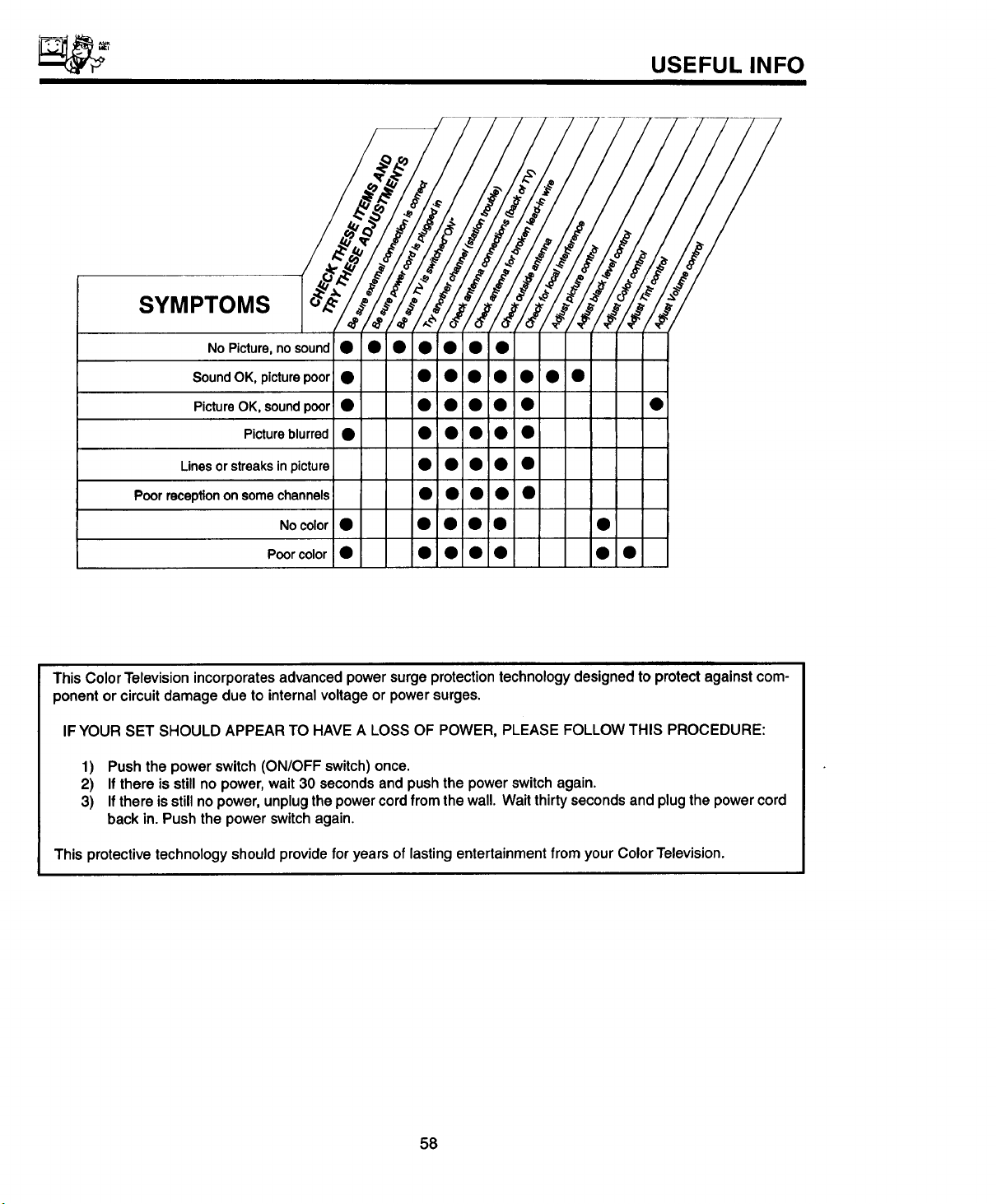
SYMPTOMS
NO Picture, no sound • • • • •i• •
Sound OK, picture poor • • • • • • • •
Picture OK, sound poor • • • • • • •
Picture blurred • •: •i • • •
Lines or streaks in picture • • • •
Poor reception on some channels • • • •
No color • • • • • •
USEFUL INFO
Poor color • • • • • • •
ii
This Color Television incorporates advanced power surge protection technology designed to protect against com-
ponent or circuit damage due to internal voltage or power surges.
IF YOUR SET SHOULD APPEAR TO HAVE A LOSS OF POWER, PLEASE FOLLOW THIS PROCEDURE:
1) Pushthepower switch(ON/OFFswitch)once.
2) If there isstillno power,wait30 secondsandpushthepowerswitchagain.
3) If thereis stillnopower,unplugthepowercordfrom thewall.Waitthirtysecondsandplugthepowercord
backin.Pushthe powerswitchagain.
This protective technology should provide for years of lasting entertainment from your Color Television.
58
Page 59

USEFUL INFO
Featu res:
• Superfine Picture Quality
700 Line Horizontal Resolution
• Dark Tint CPT with Self Dynamic Focus Gun except 35V (Dark Tint CPT)
• Remote Transmitter
(Controls many VCR, Cable Box, and Satellite Brands)
• P-in-P Functions
• ICONS: Color Graphic Guide
• Full set of Input Jacks, including S-Video
• Closed Caption Decoder
• Comb Filter, Wide-Band Video-Amp and Temperature Control
• MTS (Multi-ChanneITelevision Sound) Stereo Broadcast Reception
• 3D Surround Sound (3 Way)
Screen Size:
Inputs: Dimensions:
• Power Input .................. AC 120V, 60Hz
• Power Consumption (operating) .......... 135W
• Power Consumption (Maximum) .......... 180W
Antenna input impedance ............. 75 Ohm • Width (in.) 311/16
Channel coverage ................... 181 ch.
VHF-Band .......................... 2 ~ 13
UHF-Band ......................... 14 ~ 69
CATV Mid Band ................... A-5 ~ A-1
................................. A-I • Weight (Ibs.) 132
Super Band ........................... J-W
Hyper Band .................... W+I - W+28 35CX30B
Ultra Band .................... W+29 - W+84
• Video ..................... 1.0Vp-p, 75 Ohm • Height (in.) 301/16
• S-Video
Luminance (Y) ............... 1.0Vp-p, 75 Ohm • Width (in.) 3531/32
Chrominance (C) ............. 1.0Vp-p, 75 Ohm
• Audio input level ................... 47k Ohm • Depth (in.) 2413/16
• Average input level ................ 470mVrms
• Maximum input level ............... 940mVrms
32V (32 inches measured diagonally) 32CXl 1B, 32TX78B, and 32TX79K
35V (35 inches measures diagonally) 35CX30B, 35TX78B, and 35TX89K
32CX11 B
• Height (in.) 2611/lS
• Depth (in,) 2233/64
• Weight (Ibs.) 184
32TX78B
32TX79K
447/8
323/8
2231/64
230
35TX88B
35TX89K
5O
3715/32
25
284
I NOTE: Due to improvements, specifications in this operating guide are subject to change without notice. 1
59
Page 60
HITACHI
USEFULINFO
To locate an authorized
HITACHI service facility
in the continental U.S.A.
and Canada,
DIAL TOLL FREE
7 days a week, 24 hours a day
1-800-448-2244
Hitachi Home Electronics (America), Inc.
Hitachi has made every effort to assure you hours of trouble free operation from your unit. However, should you
require service, a network of Hitachi Authorized Service Facilities has been established in all 50 states and Puerto
Rico. Each facility will provide you with convenient and expedient assistance. Our service "Hotline" operator will
direct you to the Hitachi Authorized Service Facility nearest you. Just present proof of purchase and/or delivery
receipts to the Hitachi Authorized Service Facility,and service will be rendered in accordance with the terms of the
limited warranty as stated on your warranty card or operating guide.
Should you have any questions regarding in-warranty service, operation or technical assistance,
please contact:
Hitachi Home Electronics (America), Inc.
3890 Steve Reynolds Blvd.
Nomross, GA 30093
Tel: 770-279-5600
For TV'$ purchased in (_nada only, please contact one of the Hitachi offices below, should you
have any questions regarding service, operation or technical assistance.
MONTREAL
9425 Trans Canada
Saint-Laurent, Quebec
H4S 1V3
Tel: (514) 956-9882
Fax: (514) 956-9761
TORONTO
6740 Campobello Road
Mississauga, Ontario
L5N 2L8
Tel: (905) 821-4545
Fax: (905) 826-6627
Hitachi Sales Corporation of Hawaii
3219 Koapaka St.
Honolulu, HI 96819
Tel: 808-839-3621
VANCOUVER
54 Humber Place, Annacia Industrial Estate
New Westminister, B.C.
V3M 6A6
Tel: (604) 526-8566
Fx: (604) 526-8127
60
Page 61

NOTES
61
Page 62
NOTES
62
Page 63

NOIES
63
Page 64

HITACHI
QR05931
 Loading...