

Hitachi 35TX59K, 35TX50B Owner’s Manual

SOLIDSTATECOLORTV
OPERATING GUIDE
Your new HITACHI COLOR TV incorporates
a host offeatures designed to give you excel-
lent performance ifyou follow the instructions
in this manual. We recommend that you read
the following instructions and "IMPORTANT
SAFEGUARDS" notice before turning on your
TV set for the first time.
This television receiver will display
television closed captioning ( 1"5"#]
or [_) in accordance with paragraph
15.119 of the FCC rules.
TABLE OF CONTENTS
IMPORTANT SAFEGUARDS .................................................... 2
HOOK UP CABLES AND CONNECTORS ................................ 5
BEFORE OPERATING YOUR TV SET ..................................... 5
ANTENNA CONNECTIONS ...................................................... 6
FRONT PANEL CONTROLS ..................................................... 7
FRONT PANEL JACKS AND CONNECTIONS ......................... 9
REAR PANEL JACKS ............................................................. 10
REAR PANEL CONNECTIONS (35TX30B) ............................ 11
REAR PANEL CONNECTIONS (35TX50B & 35TX59K) ......... 12
CONNECTING TO THE REAR SPEAKER TERMINALS ........ 13
THE GENIUS REMOTE CONTROL (CLU-850GR) ................. 14
THE GENIUS REMOTE CONTROL (CLU-692GR) ................. 16
HOW TO USE THE REMOTE TO CONTROL
YOUR TV ............................................................................. 17
SET-UP FUNCTIONS .............................................................. 21
PICTURE-IN-PICTURE (P-IN-P) FUNCTIONS ....................... 30
PICTURE FUNCTIONS ........................................................... 32
AUDIO SYSTEM SET-UP ....................................................... 34
SOUND FUNCTIONS .............................................................. 35
USING THE GENIUS REMOTE TO:
CONTROL VCR FUNCTIONS ............................................. 40
CONTROL CABLE BOX FUNCTIONS ................................ 41
LEARN ADDITIONAL FUNCTIONS ..................................... 44
ACCESSORIES PART NUMBERS ......................................... 47
REMOTE CONTROL BATTERY INSTALLATION
AND REPLACEMENT .......................................................... 48
TROUBLESHOOTING ............................................................. 50
SPECIFICATIONS ................................................................... 51
SERVICE HOTLINE .............. .................................................. 52
NOTES .................................................................................... 53
IMPORTANT SAFEGUAROS
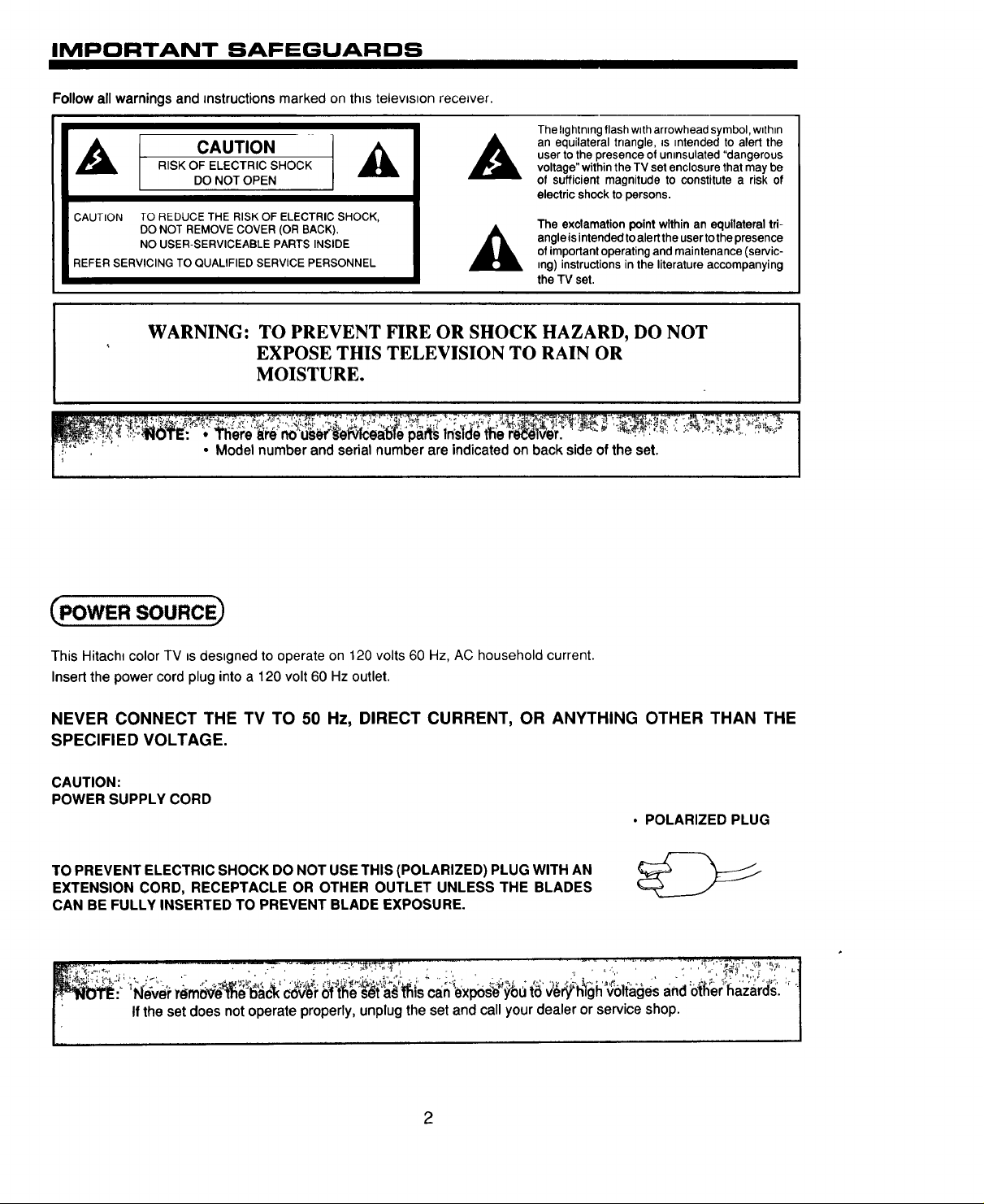
Follow all warnings and instructions marked on th_stelevlston receiver.
CAUTION
RISK OF ELECTRIC SHOCK
DO NOT OPEN
CAUTION TO REDUCE THE RISK OF ELECTRIC SHOCK,
DO NOT REMOVE COVER (OR BACK).
NO USER-SERVICEABLE PARTS INSIDE
REFER SERVICING TO QUALIFIED SERVICE PERSONNEL
WARNING: TO PREVENT FIRE OR SHOCK HAZARD, DO NOT
EXPOSE THIS TELEVISION TO RAIN OR
MOISTURE.
• Model number and serial number are indicated on back side of the set.
The hghtnmg flash with arrowhead symbol, w=thln
an equilateral trtangle, =s mtended to alert the
user to the presence of unmsulated "dangerous
voltage" within the TV set enclosure that may be
of sufficient magnitude to constitute a risk of
electric shock to persons.
The exclamationpoint wlthinan equilateraltri-
angle isintendedto alertthe user tothepresence
of importantoperatingandmaintenance(servic-
ing) instructionsinthe literatureaccompanying
the TV set.
_pOWER soLIRCE_
This Hitach_ color TV is des=gnedto operate on 120 volts 60 Hz, AC household current.
Insert the power cord plug into a 120 volt 60 Hz outlet.
NEVER CONNECT THE TV TO 50 Hz, DIRECT CURRENT, OR ANYTHING OTHER THAN THE
SPECIFIED VOLTAGE.
CAUTION:
POWER SUPPLY CORD
• POLARIZED PLUG
TO PREVENTELECTRICSHOCK DO NOTUSETHIS(POLARIZED) PLUG WITH AN
EXTENSION CORD, RECEPTACLE OR OTHER OUTLET UNLESS THE BLADES
CAN BE FULLYINSERTED TO PREVENT BLADE EXPOSURE.
i_: Never r_tn0$_'_e 6ac_kco_r 6f i_e s_ta_ls can i_xpos;_you t6 _$_"hlgh voltages and other I_azards.
i If the set does not operate properly, unplug the set and call your dealer or service shop.
/
2
IMPORTANT SAFEGUARDS
HITACHI
SAFETY POINTS YOU SHOULD KNOW ABOUT
YOUR HITACHI TELEVISION RECEIVER.
Our reputation has been built on the quality performance and ease of service of HITACHI television receivers.
Safety is also foremost in our minds in the design of these units. To help you operate these products propedy, this folder Illustrates safety tips which will be of benefit to you.
Please read it carefully and apply the knowledge you obtain from It to the proper operation of your HITACHI television receiver.
Please fill out your warranty registration card at once and mail it to HITACHI. This will enable HITACHi to notify you promptly in the improbable event that a safety problem
should be discovered In your model of product.
CAUTION:
* Read all of these instructions.
* Save these instructions for later use.
* Follow all warnings and Instructions marked
on the television receiver.
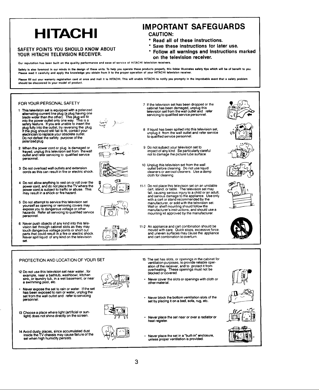
FOR YOUR PERSONAL SAFETY
1 This television set isequipped with a polarized
alternating-currentline plug(a plug havingone
blade wider than the other). This plugwill fit
intothe power outletonly one way. This isa
safetyfeature, If you are unable to insertthe
plugfully intothe outlet,try reversing the plug.
Iftha plugshould stillfail to tit, contact your
aloctr_cianto replace your obsolete outlet.
Do notdefeat the safety purpose of the
polarizedplug.
2 When the power cordor plug isdamaged or
frayed unplug this television set from thewall
outlet and refer servicing to qualified servce
personnel.
3 Do not overload wall outlets and extension
cords as this can result in fire or electric shock.
4 Do not allow anything to rest on or rollover the
power cord, and do notplace the TV where the
power cord jssubject to trafficor abuse. This
may result ina shockor fire hazard.
5 Do notattempt to service this television set
yourselfas opening or removing covers may
expose you to dangerous voltage or other
hazards. Refer all servicingto qualified service
personnel.
6 Never push objects of any kind into this tele-
vision set through cabinet slots as they may
touch dangerous voltage points or short out
parts that could result in a fire or electric shock.
Never spill liquid of any kind on the television
set.
7 If the television set has been dropped or the
cabinet has been damaged, unplug this
television set fromthe wall outlet and refer
servicing to qualified service personnel.
8 If liquid has been spilledinto this television set,
unplugit from the wall outletand refer service
to qualified service personnel.
Do not subject your television set to
impact of any kind Be particularly careful
not to damage the picture tube surface.
10
Unplugthis television set from the wall
outletbefore cleaning. Do not use liquid
cleaners or aerosol cleaners. Use a damp
cloth for cleaning.
11-1
Do not place this television set on an unstable
cart, stand, or table. The television set may
fall, causing serious injury to a child or an adult,
and serious damage to the appliance. Use only
with a cart or stand recommended by the
manufacturer, or sold with the television set.
Wall or shelf mounting should follow the
manufacturer's instructions, and should use a
mounting kit approved by the manufacturer.
11-2
An appliance and cart combination should be
moved with care. Quick stops, excessive force,
and uneven surfaces may cause the appliance
and cart combination to overturn.
PROTECTION AND LOCATION OF YOUR SET
12 Do not use thistelevision set near water...for
example, near a bathtub, washbowl, kitchen
sink, or laundry tub, ina wet basement, or near
a swimming pool, etc.
• Never expose the set to rain orwater If the sat
has been exposed to rain or water, unplug the
set from the wall outletand referto servicing
personnel,
13 Choose a place where light (artificial or sun-
light) does not shine directly on the screen.
14 Avoid dusty places, since accumulated dust
inside the "IV chassis may cause failure of the
set when high humidity persists
15 The set has slots, or openings in thecabinet for
ventilation purposes, to provide reliable oper-
ation of the receiver, and to protectit from
overheating. These openings must not be
blocked or covered.
• Never cover the slots or openings with clothor
othermaterial.
• Never block the bottomventilation slots of the
set by placing it on a bed, sofa, rug,etc.
• Never place the set near or over a radiator or
heat register.
• Never place the set in a "built-in"enclosure,
unlessproper ventilation is provided.
3

PROTECTION AND LOCATION OF YOUR SET
16-1 If an outside antenna is connected to the
television set, be sure the antenna system is
grounded so as to provide some protection
againstvoltage surgesand builtupstatic
charges, Section810 of the National Electrical
Code, NFPA No. 70-1975, provides information
with respectto proper groundingof themast
and supportingstructure, groundingof the lead-
in wireto an antenna discharge unit, size of
GnO_NO
P ANTENNA
POWEASE_V,C_GROUNmNG
4"'"---- (L_CVROOESYSTEM
_Ec _Ar,oNALELtC_R,CALCODE
EXAMPLE OF ANTENNA GROUNDING AS PER
NATIONAL ELECTRICAL CODE INSTRUCTIONS
i_c A_T2_0PAR_"b
W_RE
OISCMARGEUNiT
(NECS_CTIONel020_
GROU_O,NGCONOVCTORS
(_cSEt,beNe'0_lb
LAMPS
grounding conductors, location of antenna-
discharge unit, connection to grounding
electrode, and requirements for the grounding
electrede,
16-2
Note to CATV system installer:
(Only for the television set with CAW
reception)
This reminder is provided to call the CATV
system installer's attention to Article 820-40
of the NEC that provides guidelines for proper
grounding and, In particular, specifies that the
cable ground shall be connected to the
grounding system of the building, as close
to the point of cable entry as practical.
17
An outsideantenna system should not be
located in the vicinityof overhead powerlines
orother electricallightsorpower circuits,or
where itcan fall into suchpower lines or
circuits. When installingan outsideentenna
system, extreme care shouldbe takento keep
from touchingsuchpower lines or circuitsas
contact withthem might be fatal,
18
For added protection for this television set
during a lightning storm, or when it is left
unattended and unused for long periods of
time, unplug it from the wall outlet and
disconnect the antenna. This will prevent
damage due to lightning and power-line
surges.
OPERATION OF YOUR SET
19 This television set should be operated only
from the type of power source indicated on
the marking label. If you are not sure of
the type of power supply at your home,
consultyour television dealer orlocal
power company. Fortelevision sets
designed to operate from battery power,
refer to theoperating instructions.
IF THE SET DOES NOT OPERATE PROPERLY
22 if you are unable to restore normal operation by
following the detailed procedure in your oper-
ating instructions, do not attempt any further
adjustment. Unplug the set and call your dealer
or service technician.
FOR SERVICING AND MODIFICATION
25 Do not use attachments not recommended by
the television set manufacturer as they may
cause hazards.
26 When replacement parts are required,be sure
theservice technician has used replacement
thpertsspecified by the manufacturer that have
• same characteristics as the original part.
Unauthoirized substitutionsmay result infire,
electric shock, or other hazards.
20 If thetelevision set does not operate
normally byfollowing the operating
instructions,unplugthis television set from
the wall outlet and refer servicing to
qualified service personnel.Adjustonly
those controlsthat are covered in the
operating instructionsas improper
adjustmentof othercontrols mayresult in
damage andwilloften require extensive
workby a qualifiedtechnician to restore
thetelevision set to normal operation.
When going on a holiday: If your
television set is to remain unused for a
period of time, turn the television set "off _
and unplug it from the wall outlet.
23 Whenever the television set is damaged or
fails, or a distinct change in performance
indicates a need for service, unplug the set and
have it checked by a professional service
technician.
24 It is normal for some "IV sets to make occa- _ _ _"
when being turned on or off. If the snapping or --"
popping is continuous or frequent, unplug the
siona! snapping or popping sounds, particularly $"'_o_; !__//°''-_'_ I_ P_
set and consult your dealer or service _ S_-P
technician.
27
Upon completionof any service or repairs to
the television set, ask the service technician to
perform routine safelychecks to determine that
the television is in safe operating condition,
4
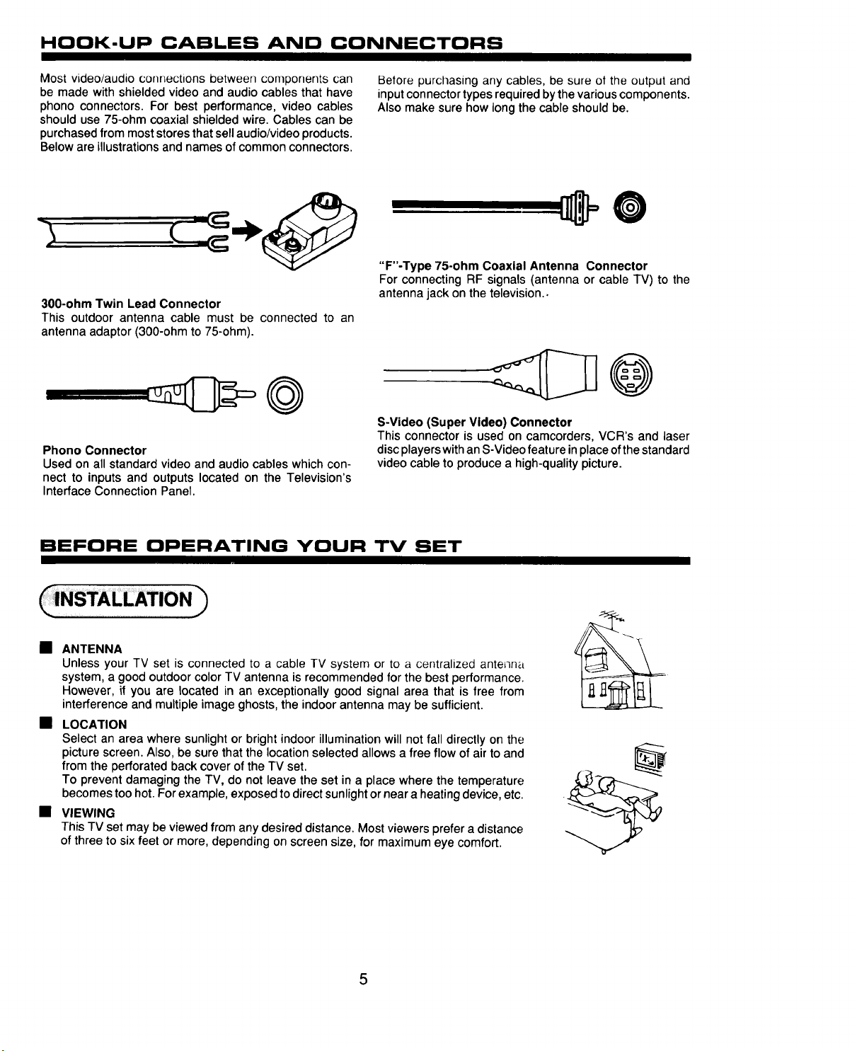
HOOK-UP CABLES AND CONNECTORS
Most video/audio connections between components can
be made with shielded video and audio cables that have
phono connectors. For best performance, video cables
should use 75-ohm coaxial shielded wire. Cables can be
purchased from most stores that sell audio/video products.
Below are illustrations and names of common connectors.
300-ohm Twin Lead Connector
This outdoor antenna cable must be connected to an
antenna adaptor (300-ohm to 75-ohm).
Phono Connector
Used on all standard video and audio cables which con-
nect to inputs and outputs located on the Television's
Interface Connection Panel.
Before purchasing any cables, be sure of the output and
input connector types required by the various components.
Also make sure how long the cable should be.
"F"-Type 75-ohm Coaxial Antenna Connector
For connecting RF signals (antenna or cable TV) to the
antenna jack on the television..
S-Video (Super Video) Connector
This connector is used on camcorders, VCR's and laser
discplayerswithan S-Video feature inplace ofthe standard
video cable to produce a high-qualitypicture.
BEFORE OPERATING YOUR TV SET
• ANTENNA
Unless your TV set is connected to a cable TV system or to a centralized antenna
system, a good outdoor color TV antenna is recommended for the best performance.
However, if you are located in an exceptionally good signal area that is free from
interference and multiple image ghosts, the indoor antenna may be sufficient.
• LOCATION
Select an area where sunlight or brightindoor illumination will notfall directly on the
picture screen. Also, be sure that the location selected allows a free flow of air to and
from the perforated back cover of the TV set.
To prevent damaging the TV, do not leave the set in a place where the temperature
becomes too hot. For example, exposed to direct sunlight or near a heating device, etc.
• VIEWING
ThisTV set may be viewed from any desired distance. Most viewers prefer a distance
ofthree to six feet or more, depending on screen size, for maximum eye comfort.
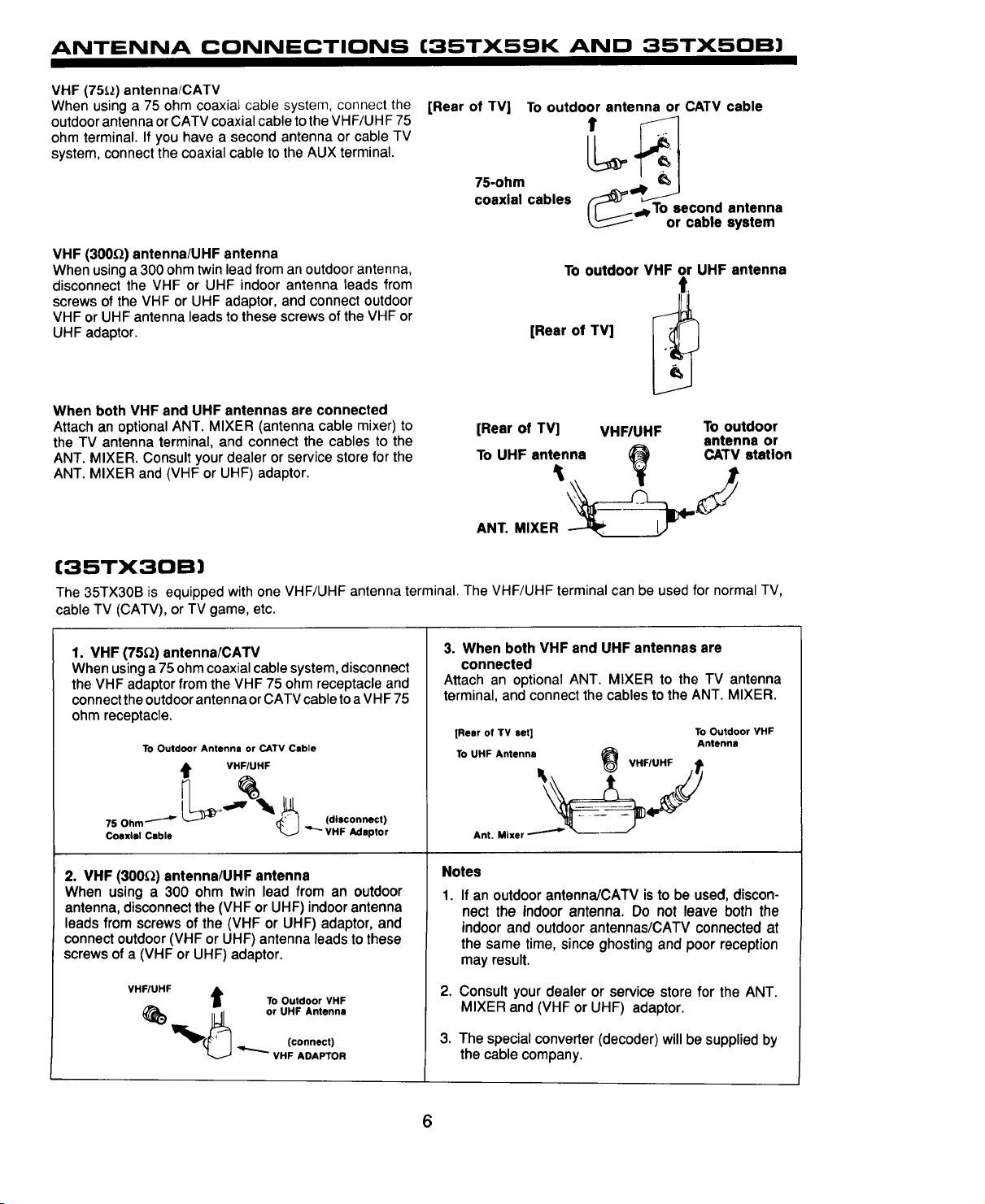
ANTENNA CONNECTIONS (35TX59K AND 35TX50B)
VHF (75_,_)antenna/CATV
When using a 75 ohm coaxial cable system, connect the
outdoor antenna or CATV coaxial cable to the VHF/UHF 75
ohm terminal. If you have a second antenna or cable TV
system, connect the coaxial cable to the AUX terminal.
[Rear of -rv]
75-ohm
coaxial cables
To outdoor antenna or CATV cable
O,ec°br_: saynstteenmna
VHF (300_) antenna/UHF antenna
When using a 300 ohm twinlead from an outdoor antenna,
disconnect the VHF or UHF indoor antenna leads from
To outdoor VHF or UHF antenna
t,
screws of the VHF or UHF adaptor, and connect outdoor
VHF or UHF antenna leadsto these screws ofthe VHF or
UHF adaptor.
[Rear of TV]
When both VHF and UHF antennas are connected
Attach an optional ANT. MIXER (antenna cable mixer) to
the TV antenna terminal, and connect the cables to the
ANT. MIXER. Consult your dealer or service store for the
[Rear of TV] VHFIUHF To outdoor
To UHF antenna (_ CATV
antenna or
station
ANT. MIXER and (VHF or UHF) adaptor.
(35TX30B)
The 35TX30B is equipped with one VHF/UHF antenna terminal. The VHF/UHF terminal can be used for normal TV,
cable TV (CATV), or TV game, etc.
1. VHF (75_) antenna/CATV
When usinga 75 ohmcoaxial cable system,disconnect
the VHF adaptor from the VHF 75 ohm receptacle and
connecttheoutdoorantenna orCATV cabletoa VHF75
ohm receptacle.
TO Outdoor Antenna or CATV Cable
VHFIUHF
3. When both VHF and UHF antennas are
connected
Attach an optional ANT. MIXER to the TV antenna
terminal, and connect the cables to the ANT. MIXER.
[Rear of TV set] To Outdoor VHF
To UHF Antenna
VHF/UHF t
Antenna
(dl_onnect)
Coaxial Cable
"'"- VH F ._udapto r
2. VHF (300_) antenna/UHF antenna
When using a 300 ohm twin lead from an outdoor
antenna, disconnectthe (VHF or UHF) indoorantenna
leads from screws of the (VHF or UHF) adaptor, and
connect outdoor (VHF or UHF) antenna leads tothese
screws of a (VHF or UHF) adaptor.
VHF/UHF
_) _1_ or UHF Antenna(connect)
J To Outdoor VHF
VHF ADAPTOR
Ant. Mixer _ _/
Notes
1 If an outdoor antenna/CATV is to be used, discon-
nect the indoor antenna. Do not leave both the
indoor and outdoor antennas/CATV connected at
the same time, since ghosting and poor reception
may result.
2,
Consult your dealer or service store for the ANT.
MIXER and (VHF or UHF) adaptor.
3.
The special converter (decoder) will be supplied by
the cable company.
6

LOCATION OF CONTROLS
FRONT VIEW
J[
k_l_ __Jl/1C_..'P_r,.l r_ I"
m
®®®®0
Details are described by the number attached to the part name (example: 0).
_) AVX (AudloNideo) selector
Press thisbutton to select the current antenna source, or
video: 1,2, or 3. Your selection is shown in the top right
corner of the screen.
(_) VOLUME level
Press these buttons for your desired sound level. The
volume level willbe displayed on the TV screen,
6
FRONT PANEL CONTROLS
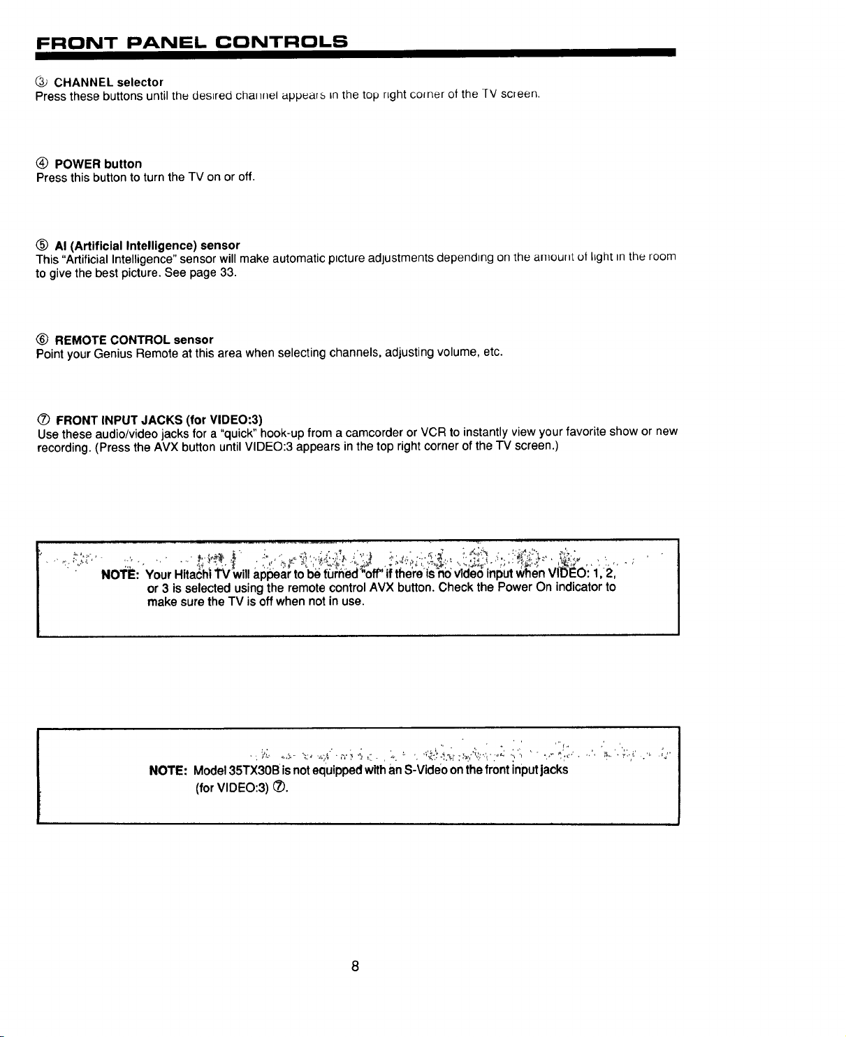
@ CHANNEL selector
Press these buttons until thu desired cha_nel appears Lnthe top nght comer of the ]_V screen.
(_ POWER button
Press this button toturn the TV on or off.
(_ AI (Artificial Intelligence) sensor
This "Artificial Intelligence" sensor will make automatic ptcture adJustments dependtng on the amount of I=ghttnthe room
to give the best picture. See page 33.
® REMOTE CONTROL sensor
Point your Genius Remote at this area when selecting channels, adjusting volume, etc.
(_) FRONT INPUT JACKS (for VIDEO:3)
Use these audio/video jacks for a "quick" hook-up from a camcorder or VCR to instantly view your favorite show or new
recording. (Press the AVX button untilVIDEO:3 appears inthe top rightcorner of the TV screen.)
No'rE: Your Hita6hi TVWIII a 1,2,
or 3 is selected usingthe remote control AVX button. Check the Power On indicator to
make sure the TV is off when not in use.
NOTE: Model 35TX30B isnotequippedwithan S-Video on thefront inputjacks
(for VIDEO:3) (_).
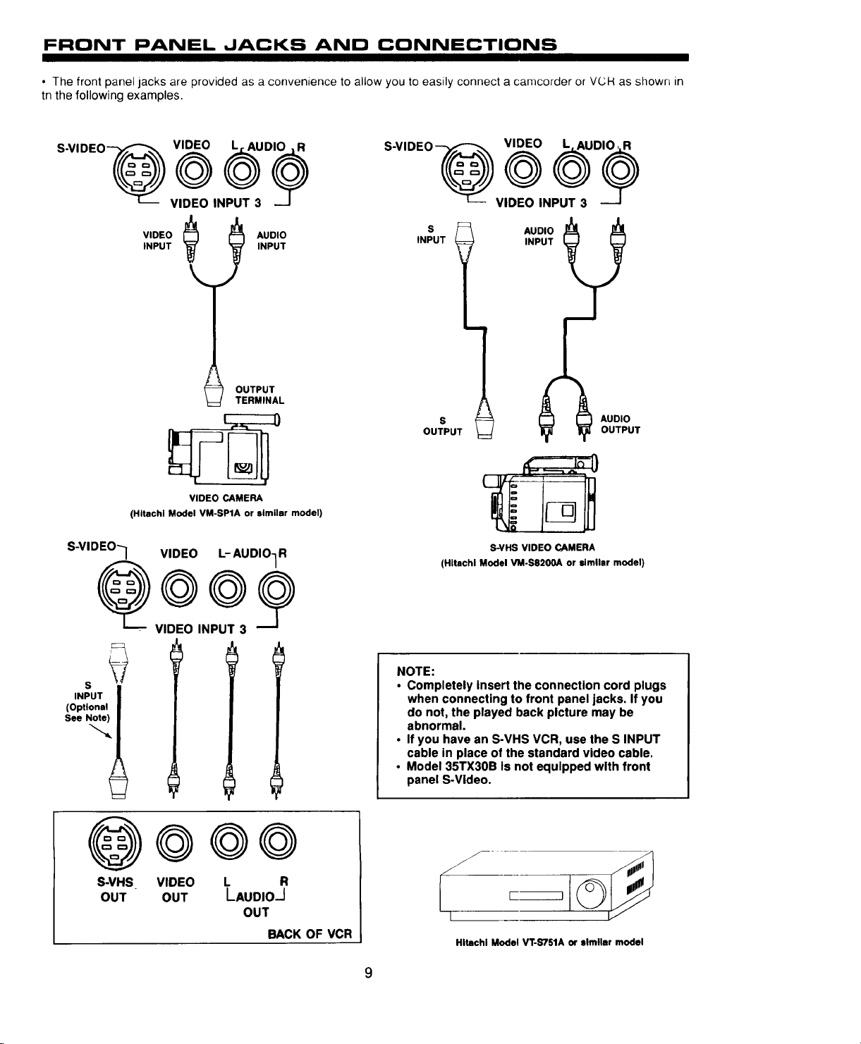
FRONT PANEL JACKS AND CONNECTIONS
• The front panel jacks are provided as a convenience to allow you to easily connect a camcorder or VCH as shown in
tn the following examples.
R
S-VIDEO_
VIDEO@ _un
VIDEO INPUT 3
VIDEO
INPUT
(Hitachi Model VM-SPIA or similar model)
_ AUDIO
OUTPUT
TERMINAL
VIDEO CAMERA
S-VIDEO--] VIDEO L-AUDIO1R
INPUT
S-VIDEO_L__ VIDEO0INPUT_3VIDE0L_AUD
S
INPUT
i
S
OUTPUT
S-VHS VIDEO CAMERA
(Hitachi Model VM-S820OA or similar model)
AUDIO
OUTPUT
©©
_ VIDEO INPUT 3
S
INPUT
(Optional
See Note)
I
S-VHS VIDEO L R
OUT OUT LAUDIO-J
OUT
BACK OF VCR
NOTE:
• Completely insert the connection cord plugs
when connecting to front panel jacks. If you
do not, the played back picture may be
abnormal.
• If you have an S-VHS VCR, use the S INPUT
cable in place of the standard video cable.
• Model 35TX30B is not equipped with front
panel S-Video.
L
Hitachi Model VT-S751A or similar model
9
REAR PANEL JACKS
_ VIE/LH=
TOC(_WERTER
[_ ' REARSPEAKER
[ NFJTI
r []
111111
VIEO
II'PUT20_l'fl T_
--._--
) (,)
NT /
®
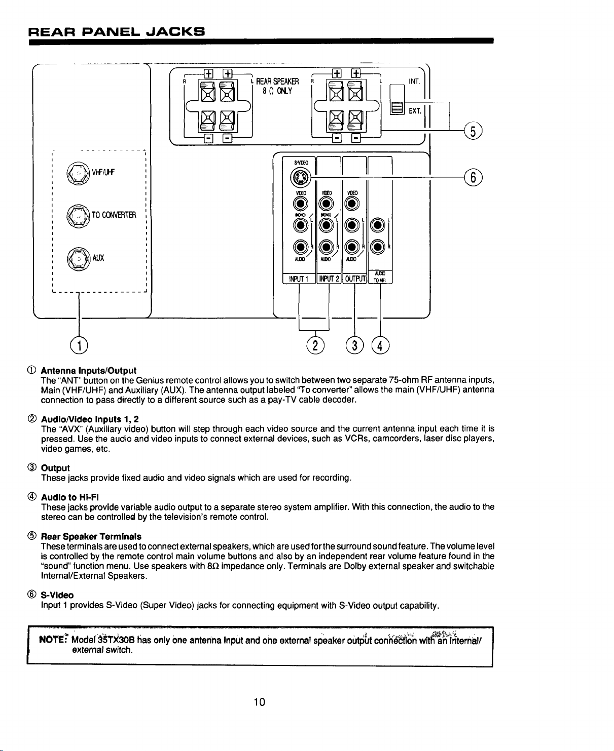
0 Antenna Inputs/Output
The "ANT" button on the Genius remote control allows you to switch between two separate 75-ohm RF antenna inputs,
Main (VHF/UHF) and Auxiliary (AUX). The antenna output labeled "To converter" allows the main (VHF/UHF) antenna
connection to pass directly to a different source such as a pay-TV cable decoder.
(_ AudioNideo Inputs 1, 2
The "AVX" (Auxiliary video) button will step through each video source and the current antenna input each time it is
pressed. Use the audio and video inputsto connect external devices, such as VCRs, camcorders, laser discplayers,
video games, etc.
<:_ Output
These jacks provide fixed audio and video signals which are used for recording.
(_ Audio to HI-FI
These jacks provide variable audio outputto a separate stereo system amplifier. With this connection, the audio to the
stereo can be controlled by the television's remote control.
® Rear Speaker Terminals
These terminals are used toconnect external speakers, whichare usedforthe surround sound feature. The volume level
iscontrolled by the remote control main volume buttons and also by an independent rear volume feature found in the
"sound" function menu. Use speakers with 8_ impedance only. Terminals are Dolby external speaker and switchable
Internal/External Speakers.
® S-Video
Input 1 provides S-Video (Super Video) jacks for connecting equipment with S-Video output capability.
NOTE_ Moder_'_TX_30Bhas only One antenna Inputand ohe external sl_aker odtlS_utcon_lo_ wlt_l_ternal/
external switch.
10
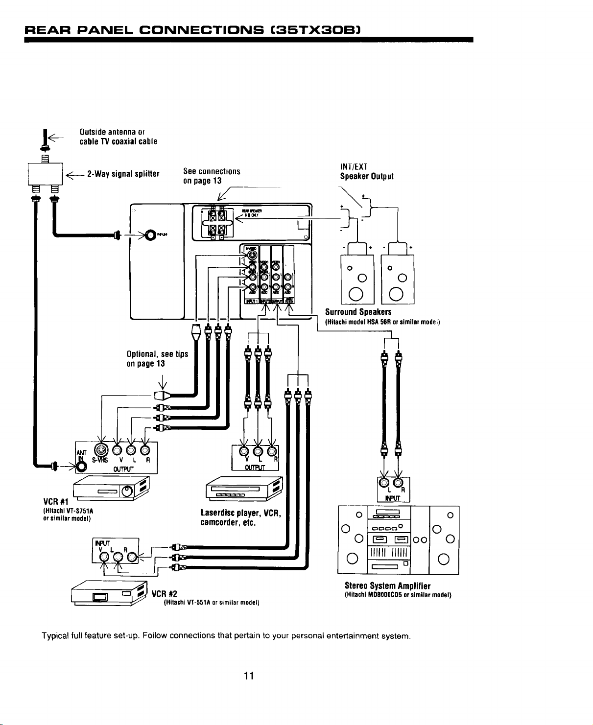
REAR PANEL CONNECTIONS (35TX30B)
!____ Outsideantennaor
cableTV coaxialcable
_ 2-Waysignalsplitter
T,_ ->0-'
Optional,see tips
onpage13
See connections
onpage13
/
1
INI/EXI
SpeakerOutput
)>
SurroundSpeakers
(Hitachi model HSA 56Ror similar model)
¢n
v L R
,; ¢==,y
VCR#1
(HitachiVT-S751A Laserdiscplayer, VCR,
orsimilar model) camcorder,etc.
[_?,__,._1,_
___ VCR#2
Typical full feature set-up. Follow connections that pertain to your personal entertainment system.
(Hitachi VT-551A orsimilar model)
11
__m_
13_ 1_3oo 0
IIIIII IIIIII
_,_ 0
StereoSystemAmplifier
(Hitachi MD8OOOCD5orsimilar model)

REAR PANEL CONNECTIONS (35TX50B AND 35TXSBK)
INT/EXT
SpeakerOutput
,i___ Outsideantennaor
_ _---.. 2-Waysignalsplitter
cableTVcoaxialcable
,-->O_ l
Optional,see tips/
See connections
onpage13
i
I00ltY
1
Dolby
Speaker
Output
1
SurroundSpeakers
(Hitachi modelHSA 56R or similar model)
v L R
OUTPUT
(HitachiVT-S751A Laserdiscplayer,VCR,
orsimilar model) camcorder,etc.
(Hitachi V't-551A or similar model)
Typical full feature set-up. Follow connections that pertain to your personal entertainment system.
12
r_n _ oo! 0
IIIIIIllllll
StereoSystemAmplifier
(Hitachi MD8000CD5 or similar model)
CONNECTING TO THE REAR SPEAKER TERMINALS
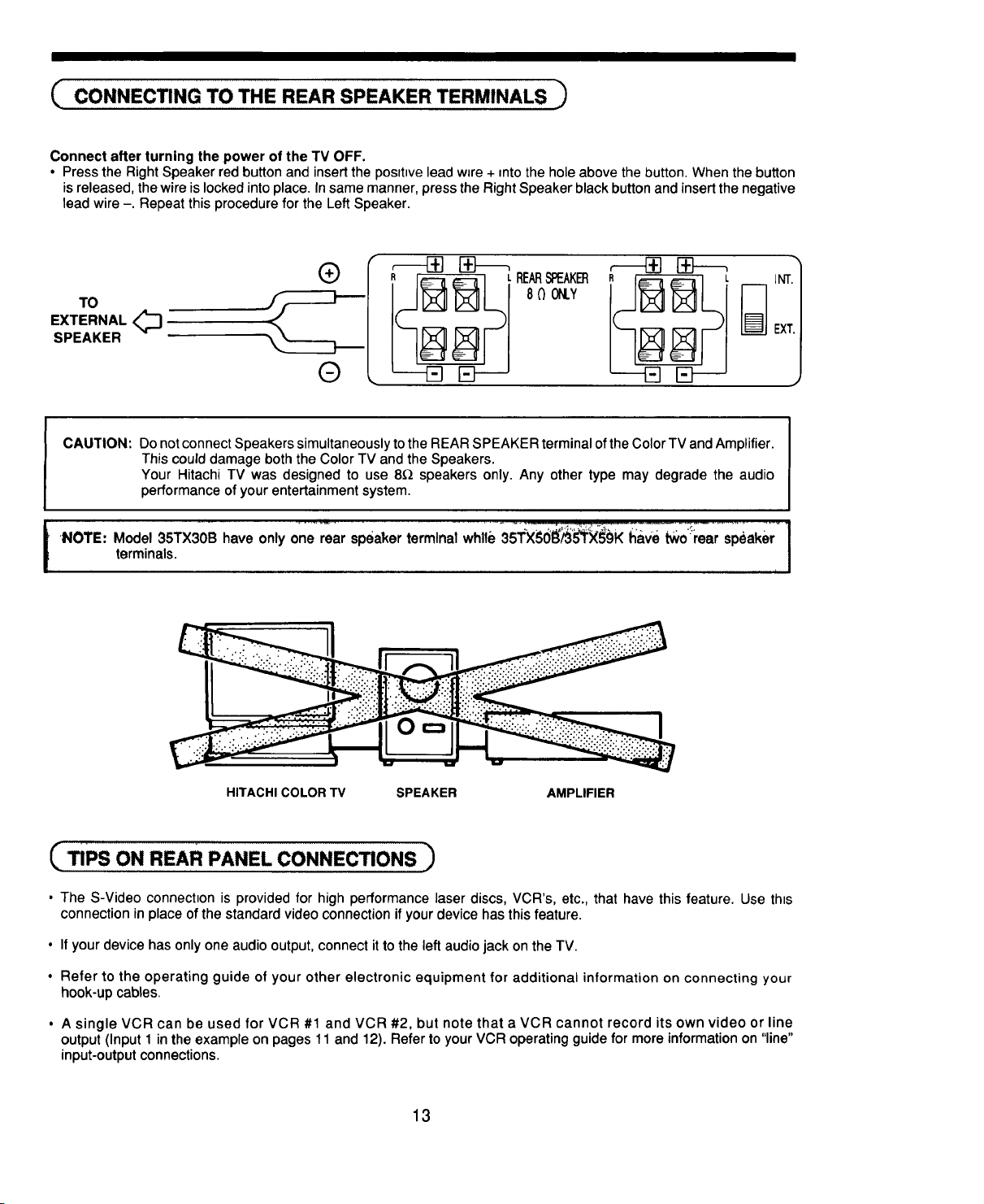
Connect after turning the power of the TV OFF.
• Press the Right Speaker red button and insert the posltwe lead w_re+ into the hole above the button. When the button
is released, the wire is locked into place. In same manner, press the Right Speaker black button and insert the negative
lead wire -. Repeat this procedure for the Left Speaker.
®
TO
EXTERNAL<_
SPEAKER
EXT.
®
CAUTION: Do not connect Speakers simultaneously to the REAR SPEAKER terminal ofthe Color TV and Amplifier.
Thiscould damage both the Color TV and the Speakers.
Your Hitachi TV was designed to use 8_ speakers only. Any other type may degrade the audio
performance of your entertainment system.
'NOTE: Model 35TX30B have only one rear speaker terminal whlle 35TX_;01_/95_XS§K have tworear speaker
I
terminals.
HITACHI COLOR TV SPEAKER AMPLIFIER
J
TiPs ON REAR PANEL CONNECTIONS ,_
• The S-Video connechon is provided for high performance laser discs, VCR's, etc., that have this feature. Use this
connection in place of the standard video connection if your device has this feature.
• If your device has only one audio output, connect it to the left audio jack on the TV.
• Refer to the operating guide of your other electronic equipment for additional information on connecting your
hook-up cables.
• A single VCR can be used for VCR #1 and VCR #2, but note that a VCR cannot record its own video or line
output (Input 1 in the example on pages 11 and 12). Refer to your VCR operating guide for more information on "line"
input-output connections.
13
THE GENIUS REMOTE CONTROL (CLU-S50GR)
In addllOn to controlhng all the funclons on your Hitachi
Color TV, the new Genius Remote transmitter is designed
to operate different types of VCR's (also abbreviated
VTR) and different types of CATV (Cable TV) con-
verters with one touch. Basic operation keys are
grouped together in one area. All other controls are
• To operate your TV, point the Genius remote at the remote sensor of the TV.
• To operate your VCR, point the remote at the remote sensor of the VCR.
separated from them and arranged in MULTI-PAGE sec-
tions, with a display that can be switched to cover any
of the four pages. Functions are arranged and properly
categorized into windows, making operation simple even
when multiple functions are to be controlled.
® ®
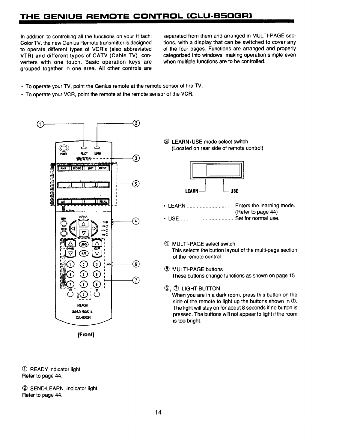
(_ LEARN/USE mode select switch
(Located on rear side of remote control)
I
I
I
I
i, i "ii X77 I,
• LEARN ................................. Enters the learning mode.
• USE ..................................... Set for normal use.
(Refer to page 44)
G_I_P_OTE
(_ READY indicator light
Refer to page 44.
SEND/LEARN indicator light
Refer to page 44.
® @!
i r _1
_TA_
CLL_G_
[Front]
(_ MULTI-PAGE select switch
This selects the button layout of the multi-page section
of the remote control.
I
I
©
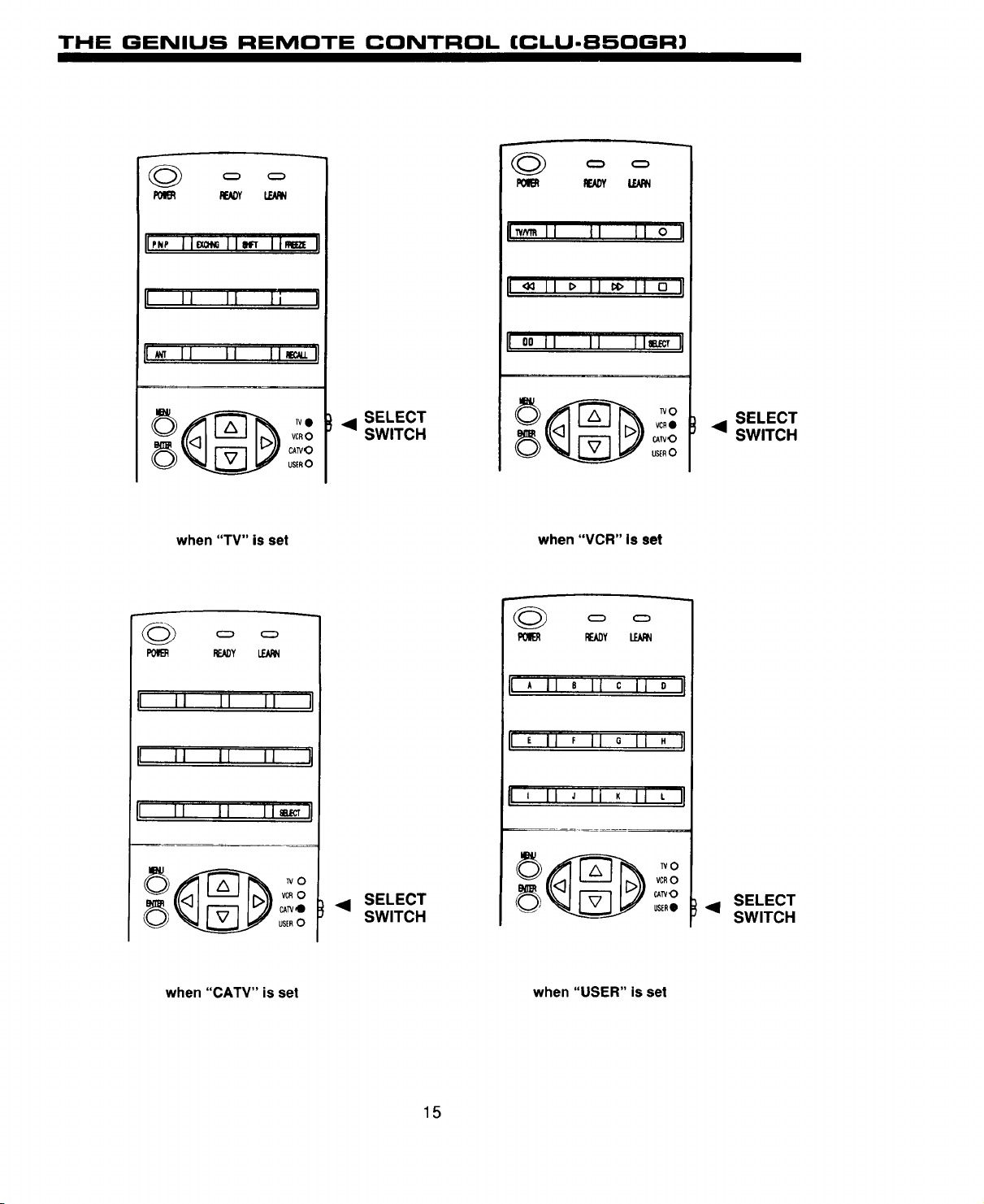
(_) MULTI-PAGE buttons
These buttons change functions as shown on page 15.
®, (_ LIGHT BUTTON
When you are in a dark room, press this button on the
side of the remote to light up the buttons shown in _.
The light will stay on for about 8 seconds if no button is
pressed. The buttons will not appear to light if the room
is too bright.
14
THE GENIUS REMOTE CONTROL (CLU-850GR)
gE_Y
IpNP11_]1_ lim_ q
I II I1 ]i
1_ 1] Ji I1_1!
vcR0
CATV,O
USER0
when "TV" is set
cz) cz)
P_:ADY !.B,qN
i JJ 11 II II
• SELECT
SWITCH
I_ II I1 II o I!
I m 11 => II _> II o II
I oo II II limpet II
lvo
VCR@
cAirO
us_nO
when "VCR" Is set
RF_Y LEARN
i A II 8 II c II 0 II
SELECT
• SWITCH
iI i i i l II Ii
II II I I i i _,_ J!
VCR0
CAW•
USER0
when "CATV" is set
SELECT
SWITCH
15
!1 , II F JIG Ij H IJ
p ' 11 J II K II L q
VCRO
CA_O
USER_ • SELECT
when "USER" is set
SWITCH
THE GENIUS REMOTE CONTROL
(CLU-692GR with P-in-P)
In addition to controlhng all the functions on your Hitachi
Color TV, the new Genius Remote control is designed to
operate different types of VCR's (also abbreviated VTR)
and different types of CATV converters (cable boxes) with
one touch. Basic operation buttons are grouped together in
one area. All other controls are separated from them and
• To operate your TV, point the Genius remote at the remote sensor of the TV.
• To operate your VCR, point the remote at the remote sensor of the VCR.
• To operate your cable box, point the remote at the remote sensor of the cable box.
arranged in MUL I I-PAGE sections, w_tha display that can
be switched to cover any of the three pages. Functions are
arranged and properly categorized into windows, making
operation simple even when multiple functions are to be
controlled.
(#
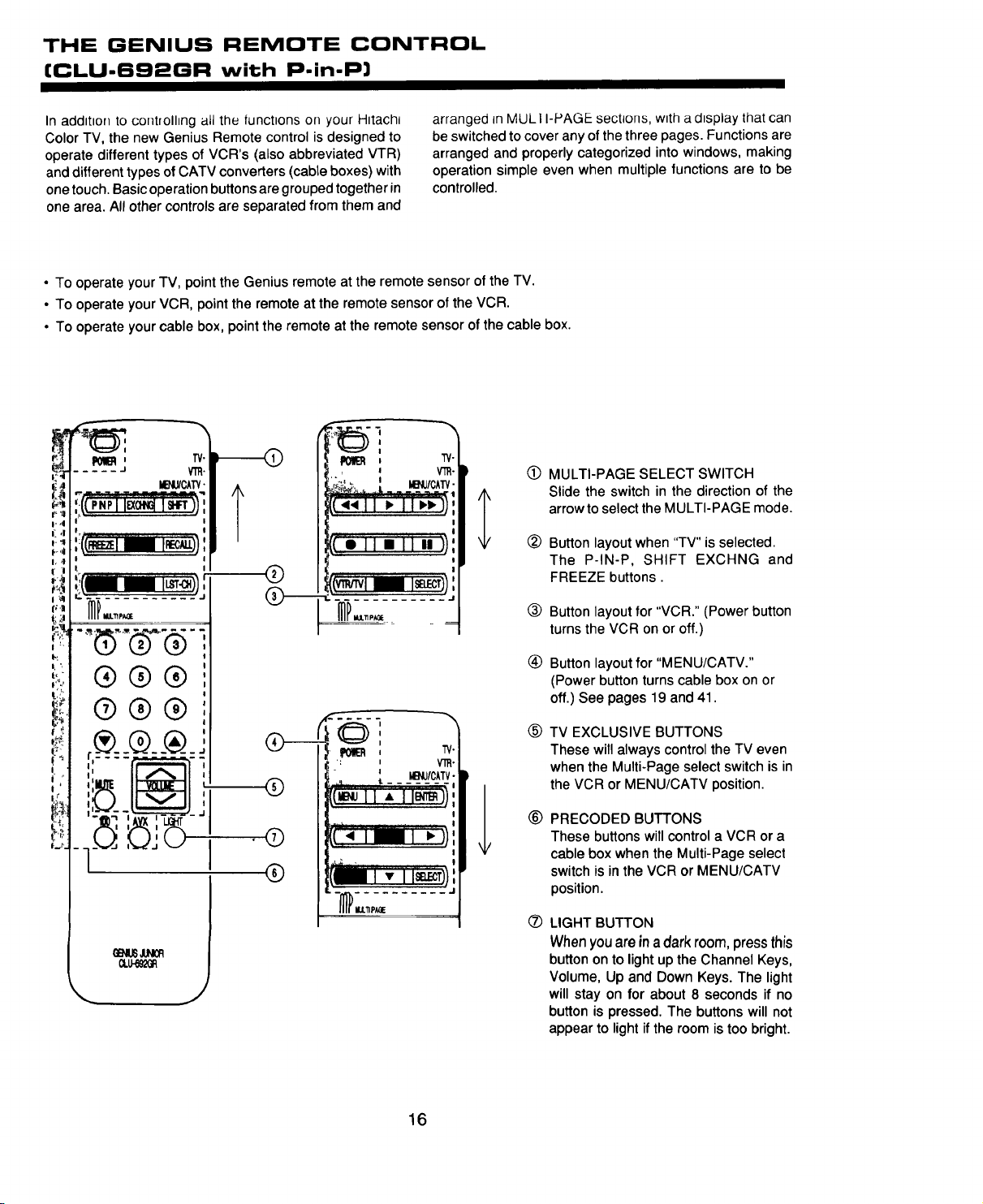
MULTI-PAGE SELECT SWITCH
Slide the switch in the direction of the
arrow to select the MULTI-PAGE mode.
®
Button layout when "TV" is selected.
The P-IN-P, SHIFT EXCHNG and
FREEZE buttons.
®
®
®
©
MENJ/CATV•
®
Button layout for "VCR." (Power button
turns the VCR on or off.)
®
Button layout for "MENU/CATV."
(Power button turns cable box on or
off.) See pages 19 and 41.
®
TV EXCLUSIVE BUTTONS
These will always control the TV even
I
I
l
I
I
!
I
when the Multi-Page select switch is in
the VCR or MENU/CATV position.
®
PRECODED BUTTONS
These buttons will control a VCR or a
cable box when the Multi-Page select
switch is in the VCR or MENU/CATV
position.
®
LIGHT BUTTON
When you are in a dark room, press this
button on to light up the Channel Keys,
Volume, Up and Down Keys. The light
will stay on for about 8 seconds if no
button is pressed. The buttons will not
appear to light if the room is too bright.
16
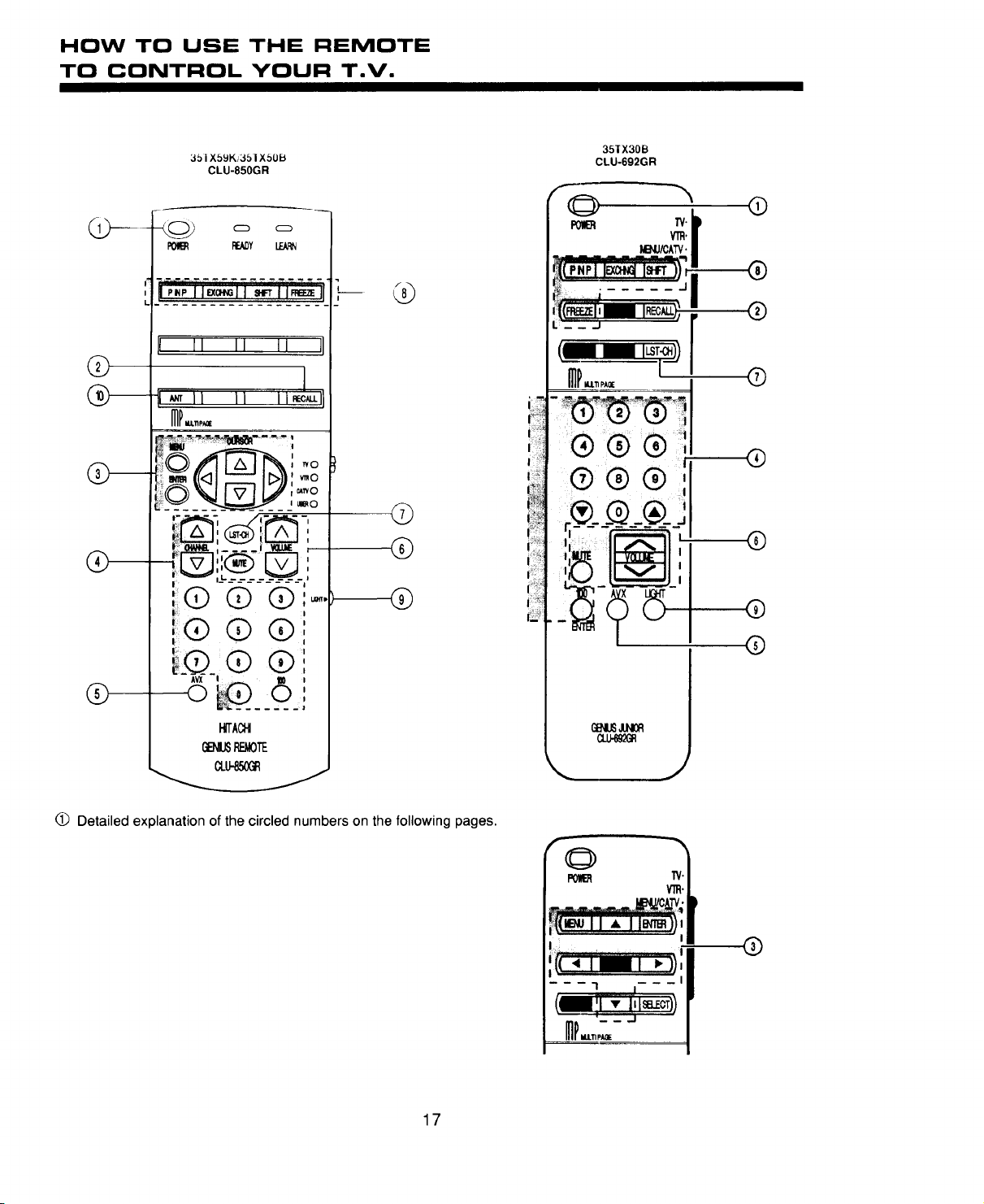
HOW TO USE THE REMOTE
TO CONTROL YOUR T.V.
®
®
351 XbgK/351 XSOB
CLU-850GR
READY
LEX_
I 11 II II I
I _ II II IIJ_-I
ilrm
_ ,
i@ @ @i_.,
i:@ ® @:
i . I
__@_.,® @,
, @
©
®
35]X30B
CLU-692GR
,,--@ -,,
,_ _:j'
®
®
®
®
®
®
®
®
_ACH
REMOTE
GW-_X_
O Detailed explanation of the circled numbers on the following pages.
17
®
 Loading...