

Page 1
These servicing instructions are for use by qualified service personnel only. To reduce the risk of electric
nless you are
Since the Panel Module and the front Filter are made of glass, handling the broken Module and Filter
and the AC/DC Power supply have
The Panel Module should not be touched with bare hands in order to protect its surface from
It is recommended that you use clean soft gloves during the replacement work in order to protect not
No.
26LD9000TA
Caution
Be sure to read this manual before servicing. To ensure safety from fire, electric shock, injury, harmful
radiation and materials, various measures are provided in this LCD Television.
Be sure to read cautionary items described in the manual before servicing.
shock, do not perform any servicing other than that described in the operating instructions u
qualified to do so.
Service Warning
1.
carefully and with caution in order not to receive injury.
2. Replacement work should be started after the Panel Module
become sufficiently cool.
3. Special care should be taken when working near the display area in order not to damage its surface.
4.
blemishes and damage.
5.
only the display area of the Panel Module but also yourself.
1. Features ...................................... 3
Contents
8. Connection Diagram .............…28
32LD9000TA
2. Specifications............................... 4
3. Component names ......................6
4. Service points ..............................8
5. Adjustment...................................9
6. Troubleshooting......................... 15
7. Block Diagram ....................... …23
9. Wiring Diagram ......................... 29
10. Basic Diagram........................... 31
11. Printed wiring board diagram .... 33
12. Disassembly diagram................ 39
13. Replacement parts list............... 43
LCD Television
1
Page 2
abels are parts
that require attention. You must follow the
presented throughout this User Manual to
The Monitor uses special tubes and tapes
ls. Moreover,
connection it is possible to sustain severe
servicing.Be sure to check everything that
ohm meter to confirm that the
the impedance value is less than 4M ohm,
CAUTION FOR SAFETY
Please read this page before repair the monitor.
The following safety precautions are designed to help you stay safe and prevent accidents during the repair
work.
Please take note of these cautionary flags.
Warning
Caution
Also note these cautionary icons
This means "CAUTION"
This means "Potential to sustain injury or even death."
This means "Potential to sustain breakage or irreparable damage."
This means "MUST"
This means "POTENTIAL ELECTRIC
SHOCK"
This means "DO NOT"
WARNING
Follow instructions. Must use same types of wires and components.
The cabinet, chassis, and l
made from insulated materia
caution notes and safety instructions
prevent damage to them or injury to
yourself.
Prevent electric shock.
Exercise caution while working on the
device as the Monitor contains high
voltage parts and power supply.It is
possible to sustain severe injury or death
if you accidentally touch the wrong
parts.You must disconnect the power
supply while servicing, reassembling, or
change parts. If you touch a live
Perform safety check when done.
some materials are kept from making
contact with the PWB for the sake of
safety.Internal leads are kept from hot
parts or high voltage parts by means of
clamps or other measures. As such, you
must restored these parts to their original
conditions in order to prevent electric
shock or fire.
Every part (such as removed screws,
components, and wiring) must be
restored to their prior conditions after
injury or death.
Use recommended components.
Use only the recommended components
or componentst that structurally identical
to the originals. This is to ensure safety
and reliability. Pay special attention to
parts in the parts list and circuit diagrams
marked with . If you use
non-recommended components, then
electric shock or fire may result.
was repaired for damage or mistakes.
Also measure the insulated impedance
with a megimpedance value is more than 4M ohm.If
then electric shock or fire may result.
Do not try to check the HDCP code and
combination circuit.
Never remove the shield case protecting
the HDCP code and combination circuit.
2
Page 3

PRECAUTIONS
Cleaning the LCD panel of the television
Please make sure to unplug the power cord before cleaning the television.
● Wipe the panel with a lint-free and dry cloth in order to prevent damage to the panel surface.
● Do not use a chemical cloth or cleaner. Depending on the ingredients, it may cause discoloration and
damage the panel surface.
● Do not wipe with a hard cloth or rub hard. It may hurt the panel surface.
● In case of the greasy dirt such as fingerprint, wipe with a lint-free cloth moistened by a diluted neutral
detergent solution, and then wipe with a soft and dry cloth.
● Do not use a spray cleaner. It could cause malfunction.
Cleaning the monitor's cabinet of the television
● The following may cause crack, deformation, and paint peeling.
● Do not wipe the cabinet with benzene, thinner, and other chemical products.
● Do not spray volatile solutions such as insecticide over the cabinet.
● Do not leave the cabinet in prolonged contact with plastic or rubber materials.
● Do not use a chemical cloth, cleaner or wax. Depending on the ingredients, it may cause crack and
deformation.
● Use a lint-free cloth to clean the cabinet and control panel of the television. In case of the heavy dirt, wipe
with a soft cloth moistened by a diluted neutral detergent solution, and then wipe with a soft and dry cloth.
● Never use the following detergents. It could cause crack, discoloration, and scratch.
● Acid/ alkaline detergent, alcoholic detergent, abrasive cleaner, powder soap, OA cleaner, car wax, glass
cleaner, etc.
1. Features
● Large-screen and high-definition LCD panel.
● Improved Digital signal processor.
● Accept more digital input devices with HDMI terminals.
● Great diversity of connecting terminals to cover wide range of audio-visual equipments.
● Enjoy the image from PC with large, high-definition LCD screen.
● Easy-to-use On-Screen Display system operating with Remote control.
● Low power consumption with Power Saving feature.
3
Page 4
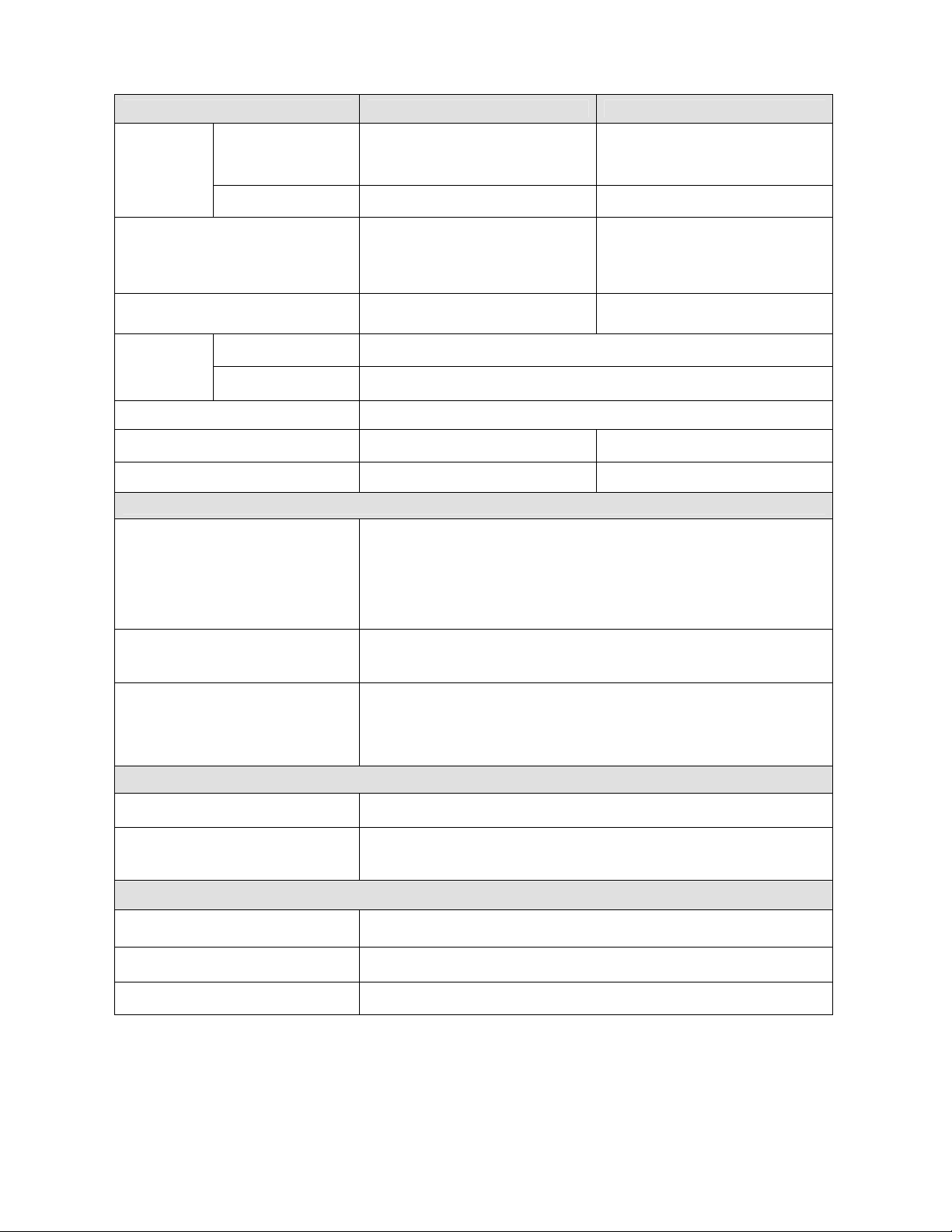
2. Specifications
SPECIFICATION 26LD9000TA 32LD9000TA
Panel
Approx. 26 inches
Display dimensions
Resolution 1366 (H) x 768 (V) pixels 1366 (H) x 768 (V) pixels
(576 (H) ×324 (V)mm,
diagonal 660.5mm)
Approx. 32inches
(698 (H) x 392 (V) mm,
diagonal 801mm)
including Stand:
Net dimensions
Net weight
Ambient
conditions
Power supply AC110 - 240V, 50/60Hz
Power consumption/at standby 125W/<1W 135W/<1W
Audio output Speaker total 14W 20W
(VIDEO input)
Input terminals
Input signals
Output signals
Temperature
Relative Humidity
664(W)x508(H)x262(D) mm
excluding Stand:
664(W)x471(H)x118.5(D) mm
including Stand:14kg
excluding Stand:12.5kg
Operating: 5°C to 35°C, Storage: 0°C to 40°C
Operating: 20% to 80%, Storage: 20% to 90% (non-condensing)
AV1.2: composite video input terminal (RCA)
S video input terminal
L/R audio input terminal (RCA)
AV3.4: component video input terminal (RCA)
L/R audio input terminal (RCA)
HDMI : HDMI input terminal
Composite video: PAL, SECAM, NTSC3.58, NTSC4.43, PAL60
Component video: 480i, 576i, 480p, 576p, 720p/50, 720p/60, 1080i/50,
1080i/60
OUTPUT (MONITOR): composite video monitor-output terminal (RCA)
OUTPUT (MONITOR): L/R audio monitor- output terminal (RCA)
OUTPUT (HEADPHONE): L/R audio monitor- output terminal (Mini-pin)
OUTPUT (SUB-WOOFER): Woofer output terminal
including Stand:
790(W)x585.5(H)x308.5(D) mm
excluding Stand:
790(W)x550(H)x120(D) mm
including Stand:19.2kg
excluding Stand:16.5kg
(RF input)
Input terminal / Receiving range ANT: 75Ω Unbalanced / 44~870MHz
PAL B, G, H / I / D, K
RF Video System
(RGB input)
Input terminals
Input signals 0.7 V, analog RGB (Recommended Signal)
Sync signals H/V separate, TTL level [2kΩ]
● The television takes at least 30 minutes to attain the status of optimal picture quality.
4
SECAM B, G / D, K / K1
NTSC-M
Analog RGB input terminal (D-sub 15-pin)
Audio input terminal (3.5mm Stereo Mini Jack)
Page 5
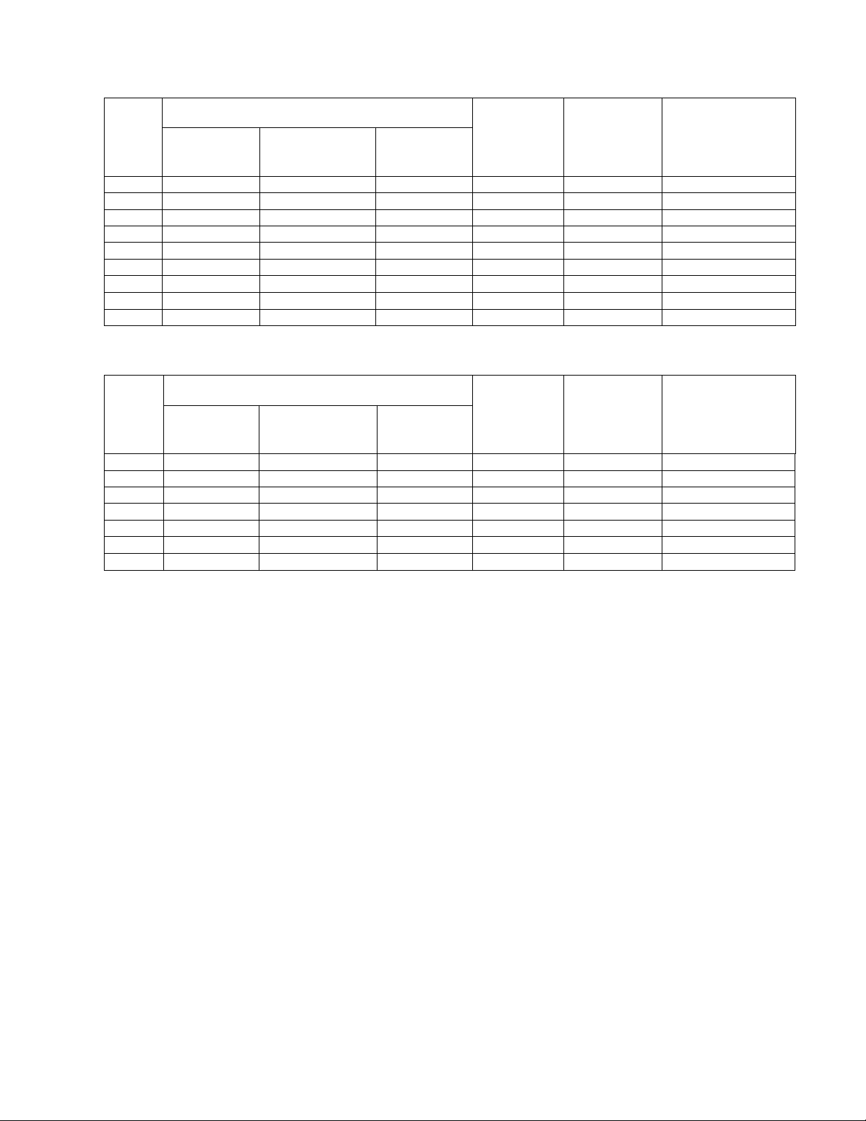
The Expression of input signal mode (format)
With HDMI INPUT
No.
Signal Name
Signal mode
Resolution
Vertical
frequency
Horizontal
frequency
(kHz)
Dot clock
frequency
(MHz)
Remarks
(Hz)
1 VGA 640x480 59.94 31.47 25.18
2 480i 720(1440)x480 60 15.75 27.00
3 480P 720x480P 60 31.5 27.00
4 576i 720(1440)x576 50 15.63 27.00
5 576P 720x576P 50 31.25 27.00
6 720P/60 1280x720 60 45 74.25
7 720P/50 1280x720 50 37.5 74.25
8 1080i/60 1920x1080 59.94 33.75 74.25
9 1080i/50 1920X1080 50 28.13 74.25
With RGB input
No.
Signal Name
Signal mode
Resolution
Vertical
frequency
Horizontal
frequency
(kHz)
Dot clock
frequency
(MHz)
Remarks
(Hz)
1 VGA 720 x 400 70.09 31.47 28.32
2 VGA 640 x 480 59.94 31.47 25.18
3 SVGA 800 x 600 56.25 35.16 36.0
4 SVGA 800 x 600 60.32 37.88 40.0
5 SVGA 800 x 600 72.19 48.08 50.0
6 XGA 1024 x 768 60.00 48.36 65.0
7 XGA 1024 x 768 70.07 56.48 75.0
The type of video board or connecting cable used may not allow for correct displays adjustment of
Horizontal Position, Vertical Position, Horizontal Clock and Clock Phase.
The television may fail to display an animation image correctly when a signal having a vertical frequency of
72Hz or higher is input to it.
The television differentiates the signal modes according to the horizontal and vertical frequencies and the
horizontal and vertical sync signal polarities. Note that different signals having all these elements alike may
be handled as the same signal.
Displaying images with more than 768 lines of vertical resolution a Full display (compressed display) can
result in the interpolation of stripes.
5
Page 6
3. Component names
1
2
3
7
5
4
6
2 1
43 2 1
4
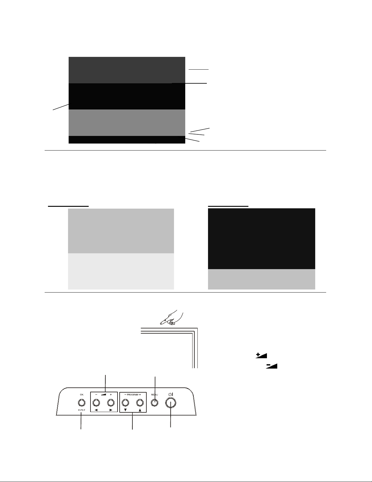
[Main unit]
Front Panel
1. Cabinet
2. Panel
3. Indicating Lamp
4. Remote Control Receiver
5. Speaker
6. Desktop Stand
7. Main Power Switch (on the left side)
Rear Panel
1. Side Input
2. Power Cord Socket
3. Terminal Board (External Device Connection)
4. Control Panel (see below for details)
26LD9000TA 32LD9000TA
3
Control Panel
These buttons are located on the top.
5, 6
7
6
3, 4
2
1
1. Sub Power button
2. Menu button
3. Program UP/ button
4. Program DOWN/ button
5. Volume UP / button
6. Volume DOWN /button
7. Input button
Page 7
[Remote Control]
816
12
59 18
14
10 1
3
4
2
6
7
11
13
15
1. Power ON/OFF
2. [Color (Red, Green, Yellow, Blue)]
3. TV Select (TV)
Press this button to change input to TV.
4. Input Select (AV1/AV2/AV3/AV4/HDMI/RGB)
Press this button to change input mode.
5. Program Select
Press these buttons to select a TV program directly.
6. Freeze [Hold]
Press this button to change the picture to freeze
mode.
7. MENU
8. Cursor
9. Volume Up/Down
10. MUTE
11. [Index]
17
12. Picture Size
Press this button to change picture size.
13. Recall
19
20
21
22
Pressing this button shows the input signal status.
14. [TV Text]
Teletext mode can be changed each time pressed in
the following sequence. TV Teletext Mix mode
15. Return
You can use this to return to the previous menu.
16. OK
17. Picture Mode
Picture mode can be changed each time pressed in
the following sequence. Dynamic Natural Cinema
18. Channel Up/Down[P +/-]
19. CHI/II
This is exclusively for TV audio A2/NICAM mode.
20. [Reveal]
21. [Sub Title]
22. [Cancel]
NOTE
Some buttons are only for Teletext mode, and other buttons have different functions in Teletext mode from
the use of TV mode. Those buttons are indicated by
[ ]
.
7
Page 8
4. Service points
The PWB assembly which has used lead free
Lead-free solder
This product uses lead-free solder (unleaded) to help protect the environment. Please read these instructions
before attempting any soldering work.
Caution: Always wear safety glasses to prevent fumes or molten solder from getting into
the eyes. Lead-free solder can splatter at high temperatures (600℃).
Lead-free solder indicator
Printed circuit boards using lead-free solder are engraved with an "F."
Properties of lead-free solder
The melting point of lead-free solder is 40-50℃ higher than leaded solder.
Servicing solder
Solder with an alloy composition of Sn-3.0Ag-0.5Cu or Sn-0.7Cu is recommended. Although servicing with
leaded solder is possible, there are a few precautions that have to be taken. (Not taking these precautions may
cause the solder to not harden properly, and lead to consequent malfunctions.)
Precautions when using leaded solder
Remove all lead-free solder from soldered joints when replacing components.
If leaded solder should be added to existing lead free joints, mix in the leaded solder thoroughly after the
lead-free solder has been completely melted (do not apply the soldering iron without solder).
Servicing soldering iron
A soldering iron with a temperature setting capability (temperature control function) is recommended.
The melting point of lead-free solder is higher than leaded solder. Use a soldering iron that maintains a high
stable temperature (large heat capacity), and that allows temperature adjustment according to the part being
serviced, to avoid poor servicing performance.
Recommended soldering iron:
Soldering iron with temperature control function (temperature range: 320-450℃)
Recommended temperature range per part:
Part Soldering iron temperature
Mounting (chips) on mounted PCB 320ºC±30ºC
Mounting (chips) on empty PCB 380ºC±30ºC
Chassis, metallic shield, etc. 420ºC±30ºC
(1) IR PWB, SW PWB, KEY PWB, SIDE I/O PWB
(2) FORMATTER PWB
(3) POWER BOARD
8
Page 9
5. Adjustment
55 75 11 0
26LD9000TA/ 32LD9000TA VGA Color Temperature Adjustment Procedure
5.1 Preparation
1. Set the signal generator (ASTRO VG859A or equivalent) to RGB, 1024*768, 60HZ, Level:0.7V, all
white pattern..
2. Turn on the set and select RGB source,perform pre-heat run more than 30 min. with Full white
pattern.
3. Prepare Minolta CA210,and calibration before adjustment.
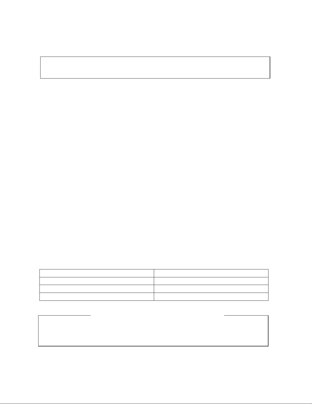
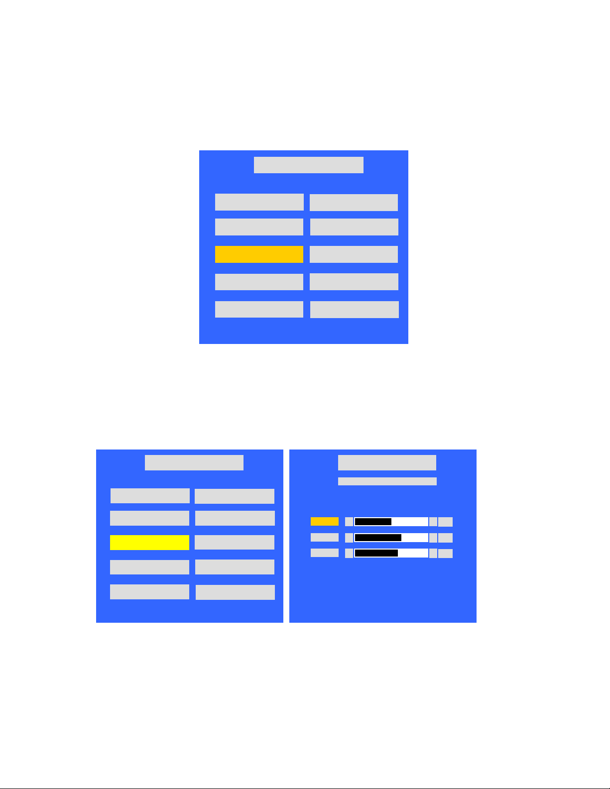
4. Press 「Menu」key , Press 「ok」 to select [Picture][Reset]「Reset」「ok」.
Picture
Picture Mode
Contrast
Brightness
Color
Sharpness
Tint
Color Temperature
Back Light
Reset
Select OK Set Return
5. Press [Menu] key exit OSD.
Dynmaic
Cool
High
Reset
50
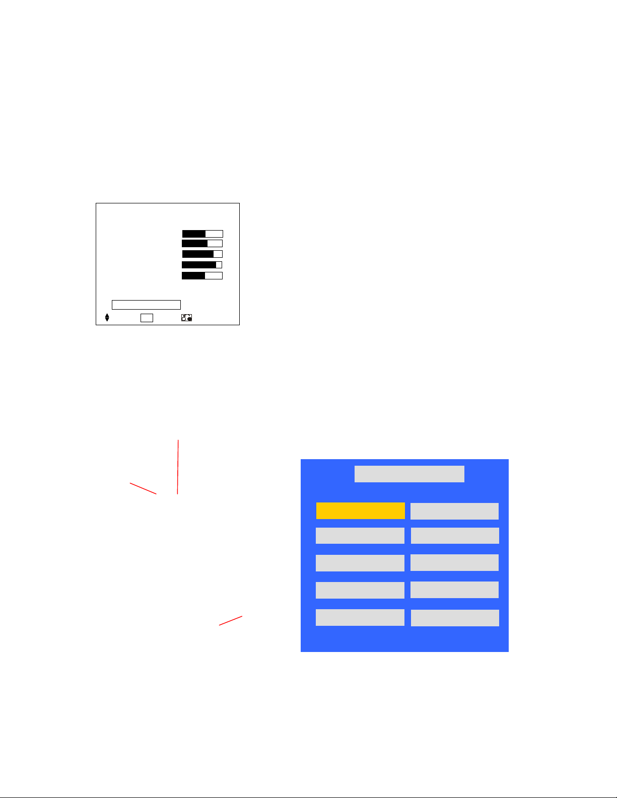
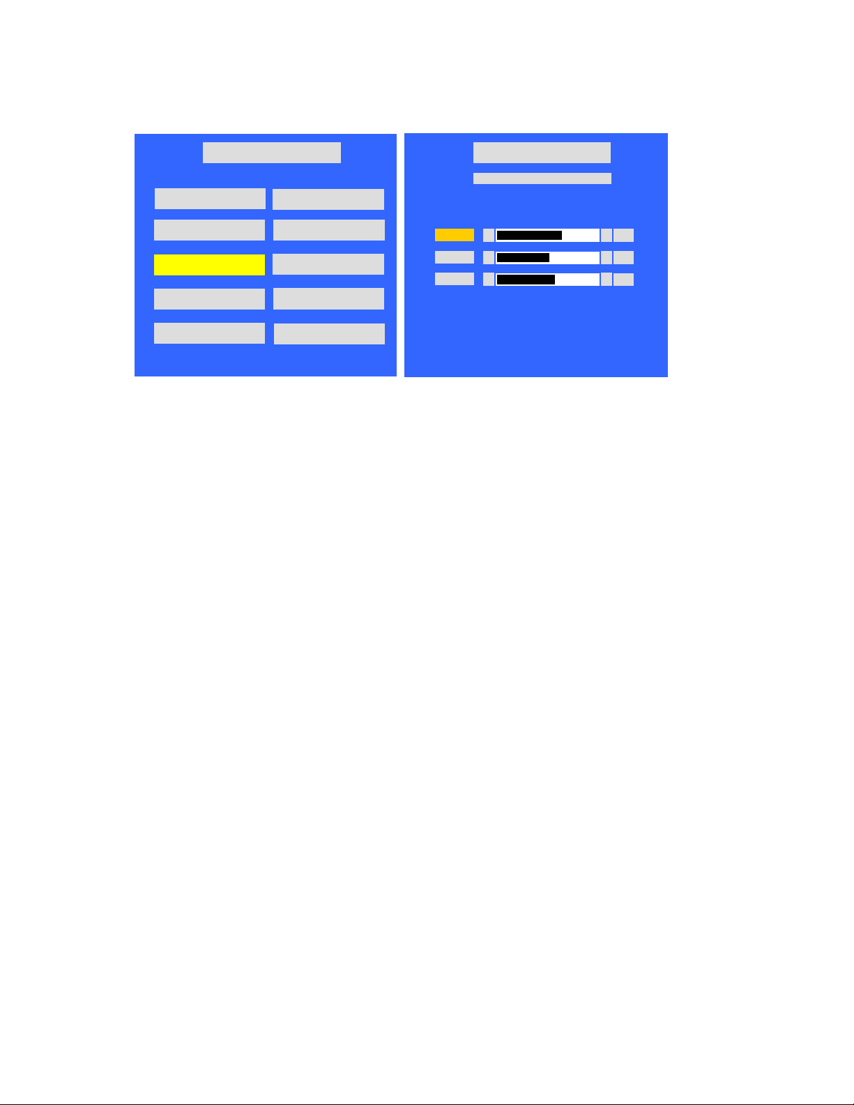
5.2 Entering into factory Mode:
In VGA mode, press “Red” key, next press “Green” key, next press “Return” key in remote control to
enter into factory mode.
Green
Factory Menu
NV CLEAR
Full Power
SourceCalibration
Reset Default
Aspect Ratio
Red
Return key
LH32CG v1.00 Oct 16.2006 21:40:50
WARM(6500K)
NORMAL(9300K)
COOL(15000K)
TimerClear
Shipping Mode
0 0 0 0 0 5 HOUR 58 MIN
9
Page 10
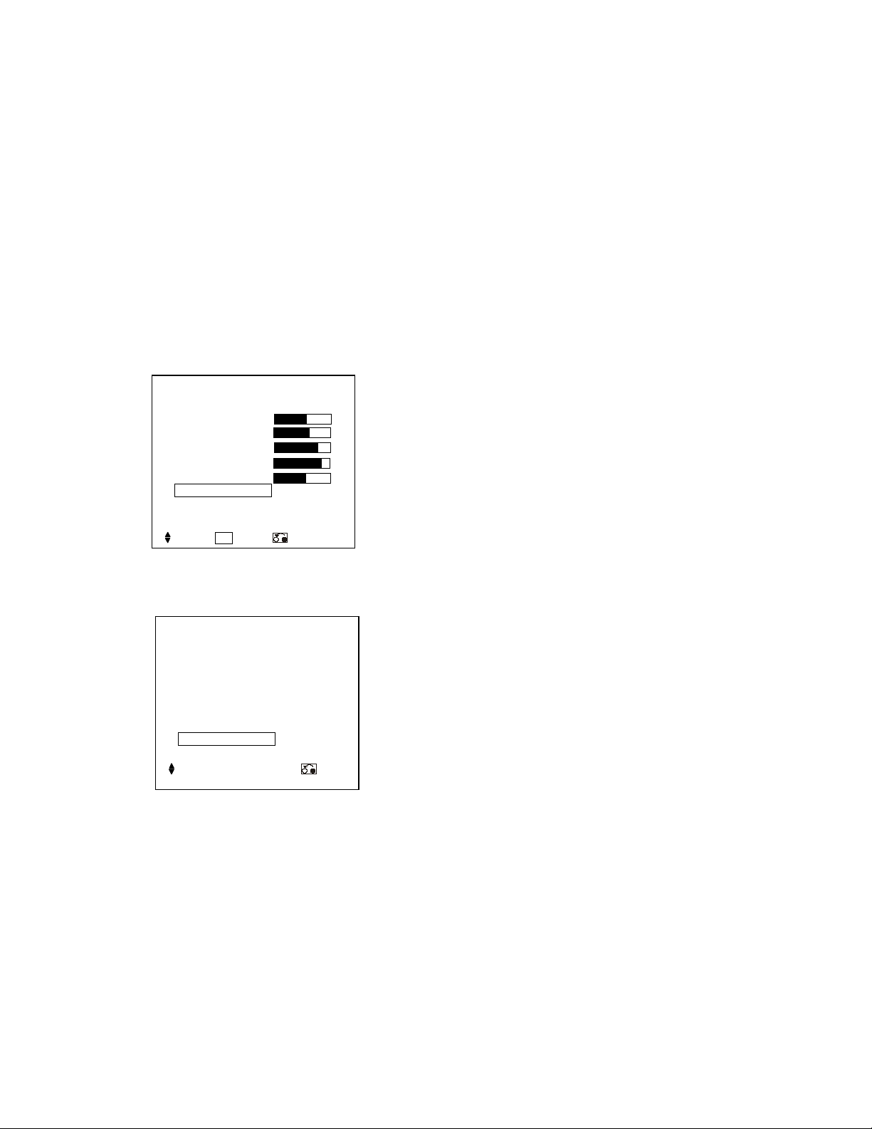
5.3 Source Calibration (RGB)
0 0 0 0 0 5
HOUR
58
MIN
0 0 0 0 0 5
HOUR
58
MIN
◄ ►
◄ ►
1. Set the signal generator to RGB, Color bar pattern (level: 0.7V, color order from left side: white,
yellow, cyan, green,magenta, red, bule, black, width ratio: 12.5% for each color),
2. Entering into factory Mode: Press up or down key of remote control to select “Source Calibration”,
Press 「OK」 key to enter the item.
Factory Menu
LH32CG v1.00 Oct 16.2006 21:40:50
WARM(6500K)
NORMAL(9300K)
COOL(15000K)
TimerClear
Shipping Mode
-> Source calibration performed automatically.
5.4 Color Temperature Adjustment
26LD9000TA
1. Set the signal generator to RGB, 1024*768, 60HZ, Level:0.56V(80%). Full white pattern.
2. Press up or down key of remote control to select “Cool”, Press 「OK」 key to enter the item.
R, G, B drive values are set for COOL, NORMAL, and WARM independently.
NV CLEAR
Full Power
SourceCalibration
Reset Default
Aspect Ratio
Factory Menu
LH26CG v1.00 Oct 16.2006 21:40:50
WARM(6500K)
NORMAL(9300K)
COOL(15000K)
TimerClear
Shipping Mode
NV CLEAR
Full Power
SourceCalibration
Reset Default
Aspect Ratio
Factory Menu
COOL(15000K)
Col or Temp eratu re
Red
Green
Blue
◄
130
►
145
140
For Red drive, keep initial value (130).
Change Green, or Blue drive as follows;
- Press “Up” or “Down” key to select the item “R”, “G”, or “B”, and press [OK] key to enter.
- Press “Left” or “Right” key to set the value.
- Press [OK] key to exit.
10
Page 11

3.Select 「Cool 15000」
(1) Cool:15000 K spec.:
x=0.266±0.001
y=0.270±0.001
(2) If the x and y value are larger than specification,
Decrease Green drive from default value.
Increase Blue drive from default value.
(3) If the x or y or both x and y value is/are smaller than specification.
Decrease Blue drive from default value
(4) According to a x and y value, please following adjustment of (4)-1 or (4)-2.
(4)-1 If x value is higher than spec
Increase Green drive from default value.
Increase Blue drive from default value.
(4)-2 If y value is higher than spec,
Decrease Green drive from default value
4.Select [Normal 9300]
Normal:9300 K spec.:
x=0.285±0.001
y=0.293±0.001
Adjust G drive (GREEN) or B drive (BLUE) to set x and y above.
5.Select [WARM]
(1) WARM:6500 K spec.:
x=0.314±0.001
y=0.327±0.001
Adjust G drive (GREEN) or B drive (BLUE) to set x and y above.
6. Exit Factory Mode:
After finish adjusting color temperature,press [MENU] to exit factory mode.
11
Page 12
32LD9000TA
0 0 0 0 0 5
HOUR
58
MIN
1. Set the signal generator to RGB,
1024*768, 60HZ, Level:0.56V(80%
). Full white pattern.
2. Press up or down key of remote control to select “Cool”, Press 「OK」 key to enter the item.
R, G, B drive values are set for COOL, NORMAL, and WARM independently.
Factory Menu
LH32CG v1.00 Oct 16.2006 21:40:50
WARM(6500K)
NORMAL(9300K)
COOL(15000K)
TimerClear
Shipping Mode
NV CLEAR
Full Power
SourceCalibration
Reset Default
Aspect Ratio
Factory Menu
COOL(15000K)
Col or Temp eratu re
Red
Green
Blue
◄
◄
◄
►
140
►
125
►
127
For Red drive, keep initial value (140).
Change Green, or Blue drive as follows;
- Press “Up” or “Down” key to select the item “R”, “G”, or “B”, and press [OK] key to enter.
- Press “Left” or “Right” key to set the value.
- Press [OK] key to exit.
3.Select 「Cool 15000」
(1) Cool:15000 K spec.:
x=0.266±0.001
y=0.270±0.001
(2) If the x and y value are larger than specification,
Decrease Green drive from default value.
Increase Blue drive from default value.
(3) If the x or y or both x and y value is/are smaller than specification.
Decrease Blue drive from default value
(4) According to a x and y value, please following adjustment of (4)-1 or (4)-2.
(4)-1 If x value is higher than spec
Increase Green drive from default value.
Increase Blue drive from default value.
(4)-2 If y value is higher than spec,
Decrease Green drive from default value
4.Select [Normal 9300]
Normal:9300 K spec.:
12
Page 13
x=0.285±0.001
55 75 11 0
y=0.293±0.001
Adjust G drive (GREEN) or B drive (BLUE) to set x and y above.
5.Select [WARM]
(1) WARM:6500 K spec.:
x=0.314±0.001
y=0.327±0.001
Adjust G drive (GREEN) or B drive (BLUE) to set x and y above.
6. Exit Factory Mode:
After finish adjusting color temperature,press [MENU] to exit factory mode.
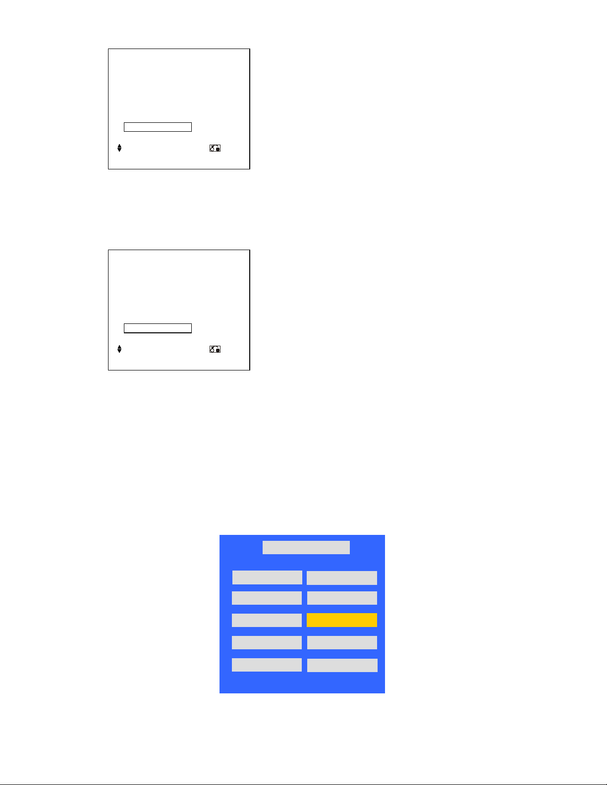
5.5 Color Temperature Check:
Press 「Menu」key , Press 「ok」 to select [Picture][Color Temp.][OK].
Picture
Picture Mode
Contrast
Brightness
Color
Sharpness
Tint
Color Temperature
Back Light
Reset
Select OK Set Return
Dynmaic
Cool
High
Reset
50
1. Select 「Cool」,check If the color temperature is in spec.
Color Temperature
Next/Prev ◄► Adjust Return
Cool:15000 K
x=0.266±0.005
y=0.270±0.005
Cool
13
Page 14
2. Select [Normal],check If the color temperature is in spec.
0 0 0 0 0
2 HOUR 50 MIN
Color Temperature
Next/Prev ◄► Adjust Return
Normal
Normal:9300K
x=0.285±0.005
y=0.293±0.005
3. Select [Warm],check If the color temperature is in spec.
Color Temperature
Warm
Next/Prev ◄► Adjust Return
Warm:6500 K
x=0.314±0.005
y=0.327±0.005
5.6 Source Calibration (Component only support AV3 port used)
1. Set the signal generator to Component, Color bar pattern (level: 0.7V, color order from left side:
white, yellow, cyan, green, magenta, red, bule, black, width ratio: 12.5% for each color)
2. Entering into factory Mode):Press up or down key of remote control to select “Comp
Calibration”, Press 「OK」 key to start adjusting..
LH32CG v1.02 Oct 31.2006 18:10:34 1
WARM(6500K)
NORMAL(9300K)
COOL(15000K)
Factory Menu
NV CLEAR
Full Power
Comp Calibration
TimerClear
Shipping Mode
-> Source calibration performed automatically.
14
Reset Default
Aspect Ratio
Page 15

5.7 Source Calibration (CVBS only support AV1 port used)
1. Set the signal generator to CVBS, Color bar pattern (level: 0.7V, color order from left side: white,
yellow, cyan, green, magenta, red, bule, black, width ratio: 12.5% for each color)
2. Entering into factory Mode:Press up or down key of remote control to select
“AV CVBS Calibration”, Press 「OK」 key to start adjusting..
LH32CG v1.02 Oct 31.2006 18:10:34 1
WARM(6500K)
NORMAL(9300K)
COOL(15000K)
TimerClear
Shipping Mode
0 0 0 0 0 2 HOUR 50 MIN
-> Source calibration performed automatically.
Factory Menu
NV CLEAR
Full Power
AV CVBS Calibration
Reset Default
Aspect Ratio
15
Page 16

6. Troubleshooting
The flow chart shown below will help you to troubleshoot your Televison set with it doesn’t display normally.
Each procedure offers a simple way to check for system errors. Before starting, ensure that there is a signal in
and that the Televison is turned on.
Power LED indicator
has no light
FIRMWARE MAIN/B
VTV-L3209 M/B
Check J12-pin 9
and FB77 =5V
(5V StandBy)
VTV-IR3209 IR/B
OK
PCBA IR/B
Check LED2-
pin 1=4V
NG
Change IR
board assembly
NG
Check J14 Pin 1= 0V
H
Change
R328
(0 Ω)
FIRMWARE MAIN/B
VTV-L3209 M/B
Check U38-pin 1
L
OK
5V
NG
Change Main
board assembly
Change power board
assembly
16
Page 17

TV has a video but no sound
VTV-IO3202 Side I/O
PCBA SIDE-IO/B
Press “ Mute” key
of remote control to
Cancel mute
function
Or adjust volume up
Check J4-pin4
= 4~5V
OK
NG
Change Side I/O
board
assembly
Check speaker unit
FIRMWARE MAIN/B
VTV-L3209 M/B
FIRMWARE MAIN/B
VTV-L3209 M/B
FIRMWARE MAIN/B
VTV-L3209 M/B
7Ω~8Ω
OK
Check J14-pin
8&9=22~23V
OK
Check U16-
pin44=4~5V
OK
Check U16-
pin45=0~0.2V
NG
NG
NG
NG
Change speaker
Change power board
assembly
Change Main board
assembly
Change Main board
assembly
OK
FIRMWARE MAIN/B
VTV-L3209 M/B
Check U32-pin3=5V
U31-pin3=8V
End
NG
Change Main board
assembly
17
Page 18

TV has a audio but no picture
FIRMWARE MAIN/B
VTV-L3209 M/B
FIRMWARE MAIN/B
VTV-L3209 M/B
FIRMWARE MAIN/B
VTV-L3209 M/B
Check J12-
pin6=5V
OK
Check J12-
pin7=1V~3.3V
OK
Check J13-
pin3=12V
OK
NG
NG
NG
Change Main board
assembly
Change Main board
assembly
Change Main board
assembly
Check backlight
Check backlight
CN1, CN4,
unit = 24V
PIN1=24V
NG
Change Power board
assembly
OK
Check LVDS
Check LVDS
cable connection
cable(308)
NG
Change panel assembly
End
18
Page 19

26LD9000TA Power Board
NG NG
OK
NG
OK NG
NG
OK OK
No O
utput Voltage +5VS, +12 V, +12V
audio, +24V
& SOUND
+5V
OK OK NG NG OK
OK
NG
+
12V
No Picture
PIN3
NO POWER
(Check PIN 2
of CNS3)
Check output
See No Pict ure
+5VS ?
OK
Check FUS E
(Check PIN 2
of CNS3)
(Check PIN2 o f
CNS3)
Open?
Open conn ector CNS3
or PIN2 lose wire
Check output
+5VS?
Under 5V
ZDS3,
CRS3,Q4,
IC7 etc
NO PICTURE
NG
STB
Over 5V
QS1,ZDS2
IC4,CRS3 ,
Q4,IC7 etc
(Check D-S,
G-S of Q3)
(Check D-S,
G-S of Q1, Q 2)
(Check D- S,
G-S of Q4 )
Check BD 1
open?
Check Q3
short?
Check Q1,Q2
short?
Check Q4
short?
See No Power
NG
BD1
Q3 etc
Q1,Q2,
IC1 etc
Q4
(Check
of CNS2)
(Check PIN3 of
CNS2)
+12Vaudio
Check CRS1
Short?
CRS1 etc
OK
See
No Picture
OK
See
No Picture
See No
Picture
cc
(Check PIN9 of
CNS2)
Check voltage
Pin 9 of CNS2
Under +12V
IC5,QS5,ICS4,RS34,
RS39,RS41,CRS1,
ZDS3,QS1,IC4 etc
Over
+12V NG
IC5,QS5,ICS4,RS34,
RS39,RS41,CRS1,
ZDS1,QS1,IC4 etc
See
No Picture
NG
Q1,Q2,CRS2,etc
(Check PIN1 of
CNS1)
+24Vinv
Check
Q1,Q2,CRS2,etc
See
(Check D-S, G-S
of Q1, Q2)
19
Page 20

(C
heck D-S, G-S
of
QS7) (Check PIN9
of
CNS2) (Check PIN1
of
CNS1)
(Check PIN9
of
CNS2) (Check PIN1
of
CNS1)
NG OK
NO
PICTURE
NG
C
heck
output
+24Vinv ?
NG OK
OK
NG
C
heck
output
C
heck
output
Panel
IC5
NG
OK
C
heck
output
IC5
Panel
Panel
NO
Output
+12Vcc, +24V
inv
+12Vcc ?
QS7,CRS4
,Q4,etc
NG
Open Connector CNS2
or PIN9 Lose wire
+12Vcc ?
NG
protect
Open connector
CNS1 and CNS4
+24Vinv ?
NG
protect
20
Page 21

32LD9000TA Power Board
QS6,IC
S7
Q3, etc
NG OK OK NG NG OK OK
NG OK
Check
output
5V
NG NG
& SOUND
+5V
See No
OK OK NG NG OK
OK
+24Vinv
See No P
ower
S
hort?
NG
+
12V
IC2,
ZDS2,QS5,
See
Under +12V
PIN3
NO POWER
(Check PIN2
of CNS3)
Check output
STB ?
(Check PIN2
of ICS7)
See
No Picture & Sound
(Check PIN2 of
CNS3)
FUSE Open?
voltage ICS7
Under 5V
etc
NO PICTURE
STB
Over 5V
ICS7 etc
NG
(Check D-S,
G-S of Q3)
(Check D-S,
G-S of Q1, Q2)
(Check D-S,
G-S of Q4)
check BD1
open?
check Q3
short?
check IC5,Q 1,Q2
short?
check Q4
short?
BD1
Q1, Q2,
IC5, etc
Q4, etc
(Check
of CNS2)
+22Vaudio
Check
DS7,CRS3
DS7,CRS3
,etc
OK
See
No Picture
OK
No Picture
Picture
cc
(Check PIN9 of
CNS2)
NG
Check voltage
Pin 8 of CNS2
QS7,CRS4,IC7,
ICS3,QS3,etc
Over
+12Vcc
ICS3, RS52, RS30,etc
See
No Picture
NG
QS1,QS2,CRS1
CRS2,etc
(Check PIN1 of
CNS1)
Check
QS1,QS2,CRS1,
CRS2,etc
See
No Picture
(Check D-S, G-S
of QS1, QS2)
21
Page 22

(Check PIN1 of
NO
PICTURE
OK NG OK NG OK
IC5 Protect
SW ON QS7
NG
NG
NO
Output
+12Vcc, +24Vinv
OK
OK
Panel NG
Open Connector
CNS1)
check output
+24Vinv ?
NG
(Check PIN9 of
CNS2)
QS7,CRS4,
Q4,etc
(Check D-S, G-S
of QS7)
check output
+12Vcc ?
QS7, Q4,
etc
Open Connector
CNS2
check output
+12Vcc ?
(Check PIN9 of
CNS2)
Q4
CNS1,CNS4
check output
+24Vinv ?
(Check PIN1 of
CNS1)
Panel NG
22
Page 23

7. Block Diagram
23
Page 24

26LD9000TA POWER BOARD
24
Page 25

25
Page 26

Power
Backlight
reset
OVP&OT
P
Ref. Voltage
ON/OFF
OC
P
32LD9000TA POWER BOARD
EMI filter
stage
Main power
stage
PFC stage
Standby power
26
stage
Power
ON/OFF
Page 27

27
Page 28

8. Connection Diagram
28
Page 29

9. Wiring Diagram
26LD9000TA
29
Page 30

32LD9000TA
30
Page 31

10. Basic Diagram
Power board
26LD9000TA
31
Page 32

32LD9000TA
32
Page 33

33
11. Printed Wiring Board Diagram
FIRMWARE Main/B
TOP SIDE
Page 34

34
BOTTOM SIDE
Page 35

POWER MODULE
26LD9000TA
35
Page 36

32LD9000TA
36
Page 37

PCBA KEY/B
TOP SIDE
BOTTOM SIDE
PCBA SIDE-IO/B
TOP SIDE
PCBA IR/B
26LD9000TA
TOP SIDE
BOTTOM SIDE
BOTTOM SIDE
37
Page 38

32LD9000TA
TOP SIDE
BOTTOM SIDE
38
Page 39

12. Disassembly Diagram
26LD9000TA
39
Page 40

40
Page 41

32LD9000TA
41
Page 42

42
Page 43

13. Replacement Parts List
26LD9000TA
ITEM PART NO DESCRIPTION SPEC
1 TE04821 PCBA IR/B VTV-IR3701 SLH37CG 1 1
2 TE04711 PCBA KEY/B VTV-K3209 SLH32CGA 1 1
3 TE04831 PCBA SWITCH/B VTV-SW3209 SLH26CG 1 1
4 TE04731 PCBA SIDE-IO/B VTV-IO3209 SLH32CG 1 1
5 TE04841 FIRMWARE MAIN/B VTV-L3209 SLH26CGA 1 1
6 TE04851 SPK SET 7W 4ohm 150x57x45 mm SLH26 1 1
7 TE04861 H-CON SET LH26 MB-SPK P&L 4P-2PX2 1 1
8 TE04862 H-CON SET LH26 MB J7 KEY PD J1 20P 1 1
9 TE04863 H-CON SET LH26 MB J11-F I/O J2 14P 1 1
10 TE04864 H-CON SET LH26 MB J26-IO J4 4P 1 1
11 TE04865 H-CON SET LH26 MB-POW 11P 1 1
12 TE04866 H-CON SET LH26 MB-POW 10P 1 1
13 TE04867 H-CON SET LH26 POW-INV 12P 1 1
14 TE04868 H-CON SET LH26 POW-INV 14P 1 1
15 TE04869 H-CON SET LH26 MB-LVDS 30P LPL 1 1
16 TE04871 WIRE SET W5.6X75X4.3D 1007#18 BLK 1 1
17 TE04881 POWER MODULE FSP164-4F01 POWER 1 1
18 TS08311 BACK COVER
19 TS08321 BEZEL ASSY Bezel + LED/IR Lens + Logo 1 1
20 TS08331 STAND ASSY Stand Assembly(add on cable clamp) 1 1
TJ05871
21
TJ05881
22 TE04891
23 TJ05891 EPE BAG LV26-K002 L820XW620 1 1
24 TJ05851 EPE SHEET(STAND) LV832H-K001 L800XW600MM 1 1
25 TE04801 POWER CORD SP60X1.8MXIS14H05/0.75BLK13AWP 0 1
26 HL02373 REMO CTRL SMK CLE-983 HITACH LH32CG 1 1
27 TJ05901 EPS BOTTOM LEFT LH26011 1 1
28 TJ05902 EPS TOP RIGHT LH2607 1 1
29 TJ05903 EPS TOP LEFT LH2608 1 1
30 TJ05904 EPS BOTTOM RIGHT LH2609 1 1
CARTON-26LD9000TA
CO
CARTON-26LD9000TA
NA
USER'S
MANUAL-26LD9000TA
With all labels without rating (Add on control
panel Ass'y,AC SW nob & decoration plate
of side IO)
C-LH26C-J88 FOR ASIA 1 0
C-LH26C-J88 FOR ASIA 0 1
U-LH26CGA-J88 E+TC+SC+R ASIA 1 1
26LD9000TA CO 26LD9000TA NA
USAGE
1 1
43
Page 44

32LD9000TA
ITEM PART NO DESCRIPTION SPEC
USAGE
32LD9000TA CO 32LD9000TA NA
1 TE04701 PCBA IR/B VTV-IR3209 SLH32CG 1 1
2 TE04711 PCBA KEY/B VTV-K3209 SLH32CGA 1 1
3 TE04721 PCBA SWITCH/B VTV-SW3209 SLH32CG 1 1
4 TE04731 PCBA SIDE-IO/B VTV-IO3209 S LH32CG 1 1
5 TE04741 FIRMWARE MAIN/B VTV-L3209 SLH32CGA 1 1
6 TE03922 INVERTER UNIT 6632L-0354A/0355A 1 1
7 TE04751 SPK SET 10W 8ohm 126.5X58X 1 1
8 TE04761 H-CON SET DV32 JOINT-POW 11P 1 1
9 TE04762 H-CON SET DV32 JOINT-POW 10P 1 1
10 TE04763 H-CON SET LV32CG MB-LVDS 30P 1 1
11 TE04764 H-CON SET LH32XG MB J26-IO J4 4P 1 1
12 TE04765 H-CON SET LH32 MB J7 KEY PD J1 20P 1 1
13 TE04766 H-CON SET LH32 MB J17 SPEAKE CABLE 1 1
14 TE04767 H-CON SET LH32 MB J11-F I/O J2 14P 1 1
15 TE04768 H-CON SET LH37/32 I NV -POW 14P-12P 1 1
16 TE04769 H-CON SET LH37/32 I NV -POW 12P 1 1
17 TE04771 NET SET W5.6X75X4.3D 144C/.12 TUBE 1 1
18 TE04781 POWER MODULE FSP207-5F05 5/12/24/24VAULG SW 1 1
19 TS08071 BACK COVER
20 TS08081 BEZEL ASSY Bezel + LED/I R Lens + Logo 1 1
21 TS08091 STAND ASSY Stand Assembly(add on cable clamp) 1 1
22
23 TE04791 USER'S MANUAL-32LD90 U-LH32CGA-J 88 S C FOR CHINA 1 1
24 TJ05841 EPE BAG LV32DA-K002 FOR MO 1 1
25 TE04801 POWER CORD SP60X1.8MXIS14H05/0.75BLK13AWP 0 1
26 HL02373 REMO CTRL SMK CLE-983 HITACH 1 1
27 TJ05861 EPS FORM BOTTOM RIGH LV320D EPS FORM BO 1 1
28 TJ05862 EPS FORM BOTTOM LEFT LV320E EPS FORM BO 1 1
29 TJ05863 EPS FORM TOP RIGHT LV320F EPS FORM TO 1 1
30 TJ05864 EPS FORM TOP LEFT LV320G EPS FORM TO 1 1
TJ05821 CARTON-32LD9000TA CO C-LH32CGA-J88 FOR ASIA 1 0
TJ05831 CARTON-32LD9000TA NA C-LH32C-J88 FOR ASIA 0 1
With all labels without rating (Add on control panel
Ass'y,AC SW nob & decoration plate of side IO)
1 1
44
 Loading...